cilindri idraulici iso 6020/2 a tiranti cilindri idraulici ... · cilindri idraulici a tiranti,...
TRANSCRIPT
1
SERVOCILINDRI ISO 6020/2ISO 6020/2 SERVOCYLINDERS
CILINDRI IDRAULICI ISO 6020/2 A tIRANtItIE-RODS ISO 6020/2 HYDRAULIC CYLINDERS
CILINDRI IDRAULICI ISO 6020/2 CON CONtROfLANgECOUNtER FLANGES ISO 6020/2 HYDRAULIC CYLINDERS
CILINDRI IDRAULICI ISO 6022ISO 6022 HYDRAULIC CYLINDERS
SERVOCILINDRI ISO 6022ISO 6022 SERVOCYLINDERS
ACCESSORI PER CILINDRI IDRAULICI ISO ACCESSORIES FOR ISO HYDRAULIC CYLINDERS
CILINDRI IDRAULICI COMPAttI LEggERILIGHt COMPACt HYDRAULIC CYLINDERS
CILINDRI IDRAULICI COMPAttI PER IMPIEgHI gRAVOSIHEAVY DUtY COMPACt HYDRAULIC CYLINDERS
AttUAtORI ROtANtIROtARY ACtUAtORS
tABELLE tECNICHEtECHNICAL tABLES
26-27
4-15
16-25
30-37
38-39
40-41
44-47
48-51
54-57
60-63
1
2
3
4
5
6
3
CILINDRI IDRAULICI ISO 6020/2 A tIRANtItIE-RODS ISO 6020/2 HYDRAULIC CYLINDERS
CODICE DI ORDINAzIONEORDERING CODE
CARAttERIStICHE tECNICHE tECHNICAL CHARACtERIStICS
EStREMItà StELOROD END
PIAStRE INCORPORAtE INCORPORAtED PLAtES
SERVOCILINDRI ISO 6020/2ISO 6020/2 SERVOCYLINDERS
ANCORAggI MOUNtING
CODICE DI ORDINAzIONEORDERING CODE
SENSORI DI PROSSIMItàPROXIMItY SWItCHES
CARAttERIStICHE tECNICHE tECHNICAL CHARACtERIStICS
DIMENSIONI DIMENSION
OPzIONIOPtIONS
SENSORI MAgNEtICIMAGNEtIC SWItCHES
CILINDRI IDRAULICI ISO 6020/2 CON CONtROfLANgEWItH COUNtER FLANGES ISO 6020/2 HYDRAULIC CYLINDERS
CARAttERIStICHE tECNICHE tECHNICAL CHARACtERIStICS
EStREMItà StELOROD END
ANCORAggI MOUNtING
CODICE DI ORDINAzIONEORDERING CODE
DIMENSIONI DIMENSION
OPzIONI E SENSORI DI PROSSIMItà OPtIONS AND PROXIMItY SWItCHES
PIAStRE INCORPORAtE INCORPORAtED PLAtES
1-1
1-2
1-3
ACCESSORI PER CILINDRI IDRAULICI ISO ACCESSORIES FOR ISO HYDRAULIC CYLINDERS
CARAttERIStICHE tECNICHE tECHNICAL CHARACtERIStICS
1
4-5
10
13
6-8
11
14
9
12
15
16-17
22
18-20
23
21
24
25
26
27
40-41
4
1
CD/DK
Cilindri a norma Standard cylinders
Alesaggi mm Bore
Pressione barPressure
Corsa massima mmMax stroke
Tolleranza sulla corsa Stroke tolerance
Fluido Fluid Viscosità Viscosity
ISO 6020/2 - DIN 24554 a tiranti / tie rods
da 25 a 100 from 25 to 100
nominale 160operating
4000 0 + 2 mm Norma ISO 8131 ISO 8131 Standard
Olio idraulico minerale / Hydraulic mineral oil Esteri fosforici / Phosphoric estersAcqua glicole / HFC-fluid
12... 90 mm2/S
CaratteristiChe teCniChe / SpecificationS
CD DKda 125 a 200 from 125 to 200
max 210
CILINDRI IDRAULICI ISO 6020/2 A tIRANtItIE-RODS ISO 6020/2 HYDRAULIC CYLINDERS
CARAttERIStICHE tECNICHEtECHNICAL CHARACtERIStICS
MD MaGnetiCO / MaGnetic
Cilindri a norma Standard cylinders
Alesaggi mmBore
Pressione barPressure
Temperatura fluido ˚CFluid temperature
Corsa massima mmMax stroke
Tolleranza sulla corsa Stroke tolerance
Fluido Fluid
Viscosità Viscosity
ISO 6020/2 DIN 24554 a tiranti / tie rods
da 25 a 125 from 25 to 125
max 160
Compatibilmente con i limiti di temperatura d’esercizio dei sensori magnetici. Compatibly with magnetic proximity switches operating temperature limits.
4000 0 + 2 mm Norma ISO 8131 ISO 8131 Standard
Olio idraulico minerale / Hydraulic mineral oil Esteri fosforici / Phosphoric estersAcqua glicole / HFC-fluid
12... 90 mm2/S
CaratteristiChe teCniChe / SpecificationS
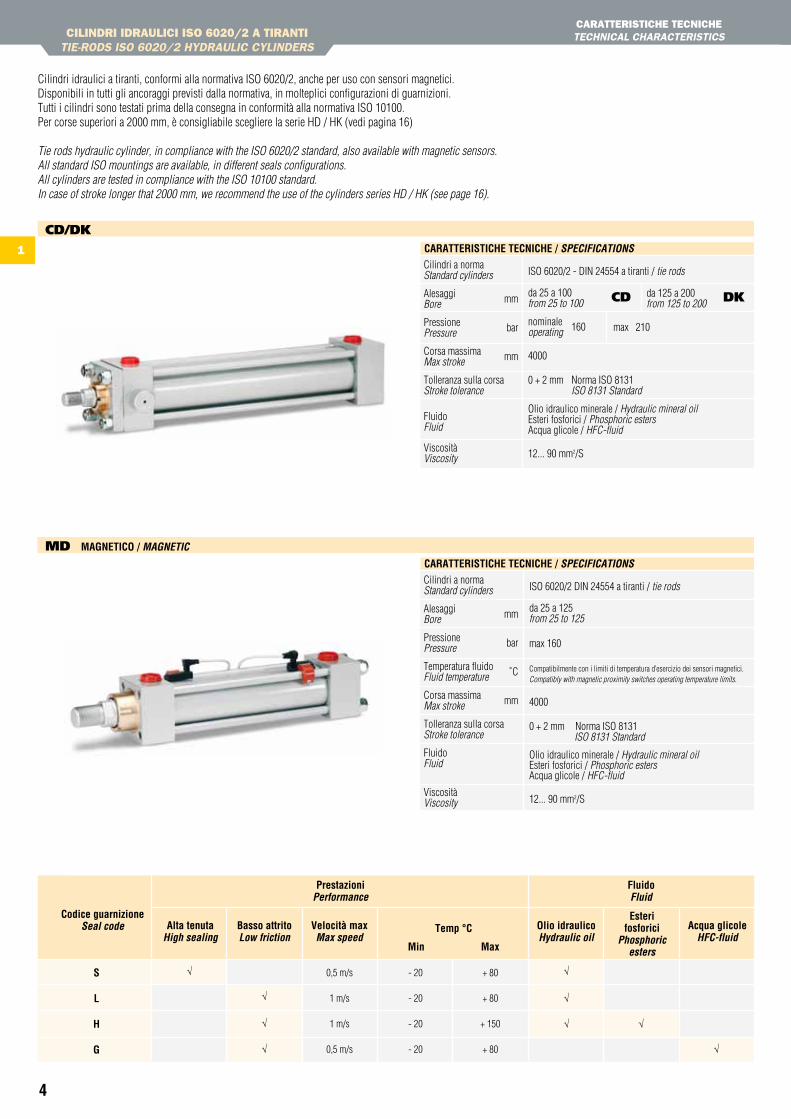
Cilindri idraulici a tiranti, conformi alla normativa ISO 6020/2, anche per uso con sensori magnetici.Disponibili in tutti gli ancoraggi previsti dalla normativa, in molteplici configurazioni di guarnizioni.Tutti i cilindri sono testati prima della consegna in conformità alla normativa ISO 10100.Per corse superiori a 2000 mm, è consigliabile scegliere la serie HD / HK (vedi pagina 16)
Tie rods hydraulic cylinder, in compliance with the ISO 6020/2 standard, also available with magnetic sensors.All standard ISO mountings are available, in different seals configurations.All cylinders are tested in compliance with the ISO 10100 standard.In case of stroke longer that 2000 mm, we recommend the use of the cylinders series HD / HK (see page 16).
0,5 m/s
1 m/s
1 m/s
0,5 m/s
- 20
- 20
- 20
- 20
+ 80
+ 80
+ 150
+ 80
Codice guarnizioneSeal code alta tenuta
High sealingOlio idraulicoHydraulic oil
esterifosforici
phosphoric esters
acqua glicoleHfc-fluid
Basso attritoLow friction
Velocità maxMax speed
temp °C
Min Max
Prestazioniperformance
Fluidofluid
s L h G
√
√
√
√
√
√
√ √
√

5
1
CILINDRI IDRAULICI ISO 6020/2 A tIRANtItIE-RODS ISO 6020/2 HYDRAULIC CYLINDERS
CARAttERIStICHE tECNICHEtECHNICAL CHARACtERIStICS
s L h GCava / GrooveComponente / component
Materiale / Material
14
15
16
17
18
19
20
21
Raschiatore stelo / Rod wiper
Guarnizione stelo / Rod seal
Guarnizione OR pistone / OR piston seal
Guarnizione stelo / Rod seal ISO 7425/2
NBR + PTFE NBR + PTFE NBR + PTFE CGViton® + PTFE
NBR + PTFE NBR + PTFE NBR + PTFE CGViton® + PTFE
PU NBR + PTFE NBR + PTFE CGViton® + PTFE
Viton® + PTFE
NBR
NBR + PTFE
NBR
NBR + PTFE
NBR
NBR + PTFE CG
Viton®
NBR NBR NBRViton®
NBR + PU NBR + PTFE NBR + PTFE CGViton® + PTFE
ISO 7425/2
ISO 7425/1
Guarnizione OR canna / OR tube seal
Guarnizione testata-boccola / Head-bushing sealing
Guarnizione pistone / Piston seal
Guida pistone / Piston guide ResinaResin
ResinaResin
ResinaResin
ResinaResin
1142 6 9 12
14
10875431
15 2118 1819 201617
13
CD CiLinDrO / cYLinDeR
24
20 21
2322
19
MD VersiOne MaGnetiCa / MaGnetic VeRSion
DK CiLinDrO / cYLinDeR
Materiale / Material spec.Componente / componentFlangia chiusura / Closing flange
Bronzo / BronzeBoccola di guida / Guide bushing
Testata anteriore / Front head
Spillo regolazione frenatura + sfiato /Cushioning adjusting + air bleed
Levigato / Honed H8 - Ra 0.40 µmCr 25 µm ISO f7 - Ra 0.20 µm
Canna / Cylinder body
Stelo / Piston rod
Freno anteriore / Front cushioning
Pistone / Piston
Freno posteriore / Rear cushioning
Testata posteriore / Rear head
Dado autobloccante stelo / Rod self-locking nut
Dado autobloccante tirante / Tie-rod self-locking nut
Tirante / Tie-rod
Pistone magnetico / Magnetic piston
Magnete / Magnet
Canna / Cylinder body
Acciaio / Steel Brunito / Burnished
Acciaio / Steel Brunito / Burnished
Brunito / Burnished
Acciaio / Steel
Acciaio / Steel
Acciaio cromato / Chromeplated steel
Acciaio temprato / Hardened steel
Acciaio / Steel
Acciaio temprato / Hardened steel
Acciaio / Steel
Acciaio / Steel
Acciaio / Steel
Acciaio legato / Alloy steel
Acciaio INOX / Stainless steel
Acciaio INOX / Stainless steel
Filettati rullati / Rolled threaded
12
3
4
5
6
78
9
10
1112
1322
2324
Materiale / Material specifiche / SpecificationsComponente / component
3 4 5 7 8 11106 42
201917 1818 2115 1614
1312
6
1
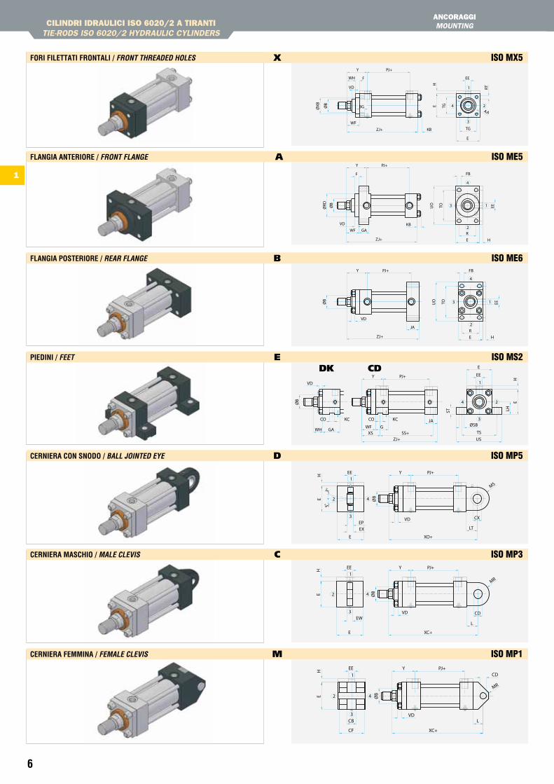
FOri FiLettati FrOntaLi / fRont tHReaDeD HoLeS x ISO MX5
FLanGia anteriOre / fRont fLanGe A ISO ME5
FLanGia POsteriOre / ReaR fLanGe b ISO ME6
PieDini / feet e ISO MS2
Cerniera COn snODO / BaLL JointeD eYe D ISO MP5
Cerniera MasChiO / MaLe cLeViS C ISO MP3
Cerniera FeMMina / feMaLe cLeViS M ISO MP1
CILINDRI IDRAULICI ISO 6020/2 A tIRANtItIE-RODS ISO 6020/2 HYDRAULIC CYLINDERS
ANCORAggIMOUNtING
VD
WH
ØXB BG
1
3
4 2AA
RT
HE TG
WF
KB TG
E
ZJ+
ØB
EEF
Y PJ+
EETOUO
FBF
Y PJ+
ØRD
KBGAWF
H
R
EZJ+
3
2
1
4
ØB
VD
4
3 1
2JA
ZJ+ HER
Y PJ+ FB
TOUO EEØB
VD
1
4
3
2
YEE PJ+
EH
E
EXEP
XO+
LT
CX
MS
ØB
VD
3°3°
MR
CD
L
XC+
EW
E
HE
PJ+EE Y
2
3
4
1
ØB
VD
1
4
3
2
YEE PJ+
EH
XC+CF
CB L
CD
MR
ØB
VD
DK CDPJ+Y
H
E
EE
E
LH
US
ØSB
TSSS+
JA
ZJ+
GXS
WF
ST
24
3
1
GAWH
CO KCCO KC
ØB
VD
7
1
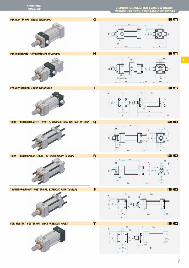
Perni anteriOri / fRont tRunnionS g ISO MT1
Perni interMeDi / inteRMeDiate tRunnionS h ISO MT4
Perni POsteriOri / ReaR tRunnionS l ISO MT2
tiranti PrOLunGati anter. e POst. / eXtenDeD fRont anD ReaR tie-RoDS Q ISO MX1
tiranti PrOLunGati anteriOri / eXtenDeD fRont tie-RoDS R ISO MX3
tiranti PrOLunGati POsteriOri / eXtenDeD ReaR tie-RoDS s ISO MX2
FOri FiLettati POsteriOri / ReaR tHReaDeD HoLeS T ISO MX6
CILINDRI IDRAULICI ISO 6020/2 A tIRANtItIE-RODS ISO 6020/2 HYDRAULIC CYLINDERS
ANCORAggIMOUNtING
24
3
1
PJ+Y EEH
ZJ+
XG
UT
TC
E ØTDØB
VD
24
3
1
Y
BDEE
PJ+
ØTDUW
ZJ+
XVmin/XVmax+ TM
UMKB
ØB
VD
4
3
2
1
EE PJ+Y
E ØTD
H
UT
TC XJ+
ZL+ KB
ØB
VD
VD
AA
BB E
TGWH
ZJ+H
E TG
DD
EEBB
PJ+Y
2
1
4
3
ØB
3
4
1
2
PJ+YEE
BB
DD
AA
ZJ+
WH
EKB
TG
TGEH
VD
ØB
BBZJ+
AA
TG
E
H
TGE
PJ+
DD
EE Y
1
3
42 ØB
VD
2 4
3
1
YEE
RT
PJ+
E TG
H
E
TG
AA
ZJ+
BGØB
VD
8
1
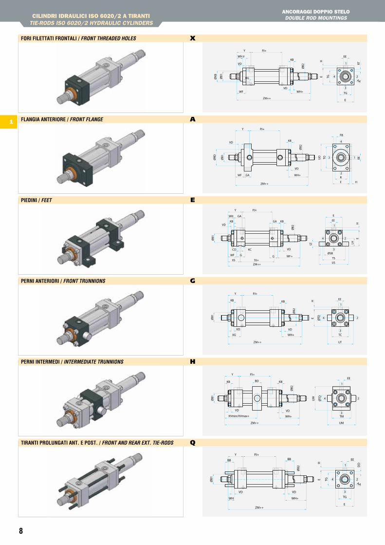
FOri FiLettati FrOntaLi / fRont tHReaDeD HoLeS x
FLanGia anteriOre / fRont fLanGe A
PieDini / feet e
Perni anteriOri / fRont tRunnionS g
Perni interMeDi / inteRMeDiate tRunnionS h
tiranti PrOLunGati ant. e POst. / fRont anD ReaR eXt. tie-RoDS Q
CILINDRI IDRAULICI ISO 6020/2 A tIRANtItIE-RODS ISO 6020/2 HYDRAULIC CYLINDERS
ANCORAggI DOPPIO StELO DOUBLE ROD MOUNtINGS
VD
ØXB ØB1
WH
BG
1
3
4 2AA
RT
EE
HE TG
TG
E
WH+WF
ZM++
F
PJ+Y
KB
VD
ØB2
EETOUO
FB
WF GA
H
R
E
WH+
ZM++
ØRD
KB
Y PJ+
3
2
1
4
VD
ØB2
ØB1
VD
GA
G
1
3
4 2
WH
HE
LHST
TSUS
ØSBWF+WF
XS
G
SS+ZM++
EE
EGA
Y PJ+
KBKB
CO KC VD
ØB2
ØB1
VD
ØTDE
TC
UT
WH+XG
ZM++
PJ+Y
EEH
1
3
4 2
KBKB
VD
ØB2
ØB1
VD
UW
ØTD
TM
UM
WH+XVmin/XVmax+
ZM++
EEBD
Y PJ+
1
3
4 2
KBKB
VD
ØB2
ØB1
VD
WH
VD
WH+
ZM++
E TG
TG
E
AA
DD
EEBB
H
PJ+
BB
Y
2
1
4
3
ØB1
ØB2
VD
9
1
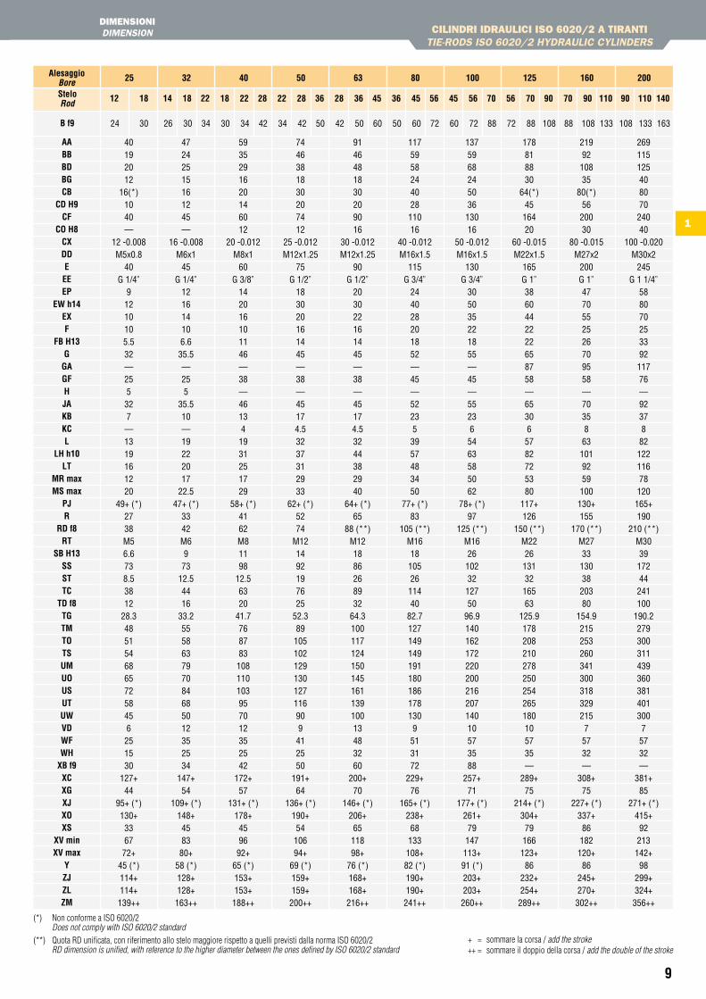
CILINDRI IDRAULICI ISO 6020/2 A tIRANtItIE-RODS ISO 6020/2 HYDRAULIC CYLINDERS
DIMENSIONIDIMENSION
(*) Non conforme a ISO 6020/2 Does not comply with ISO 6020/2 standard
(**) Quota RD unificata, con riferimento allo stelo maggiore rispetto a quelli previsti dalla norma ISO 6020/2 RD dimension is unified, with reference to the higher diameter between the ones defined by ISO 6020/2 standard
+ = sommare la corsa / add the stroke++ = sommare il doppio della corsa / add the double of the stroke
aaBBBDBGCB
CD h9CF
CO h8CXDDeeeeP
eW h14eXF
FB h13G
GaGFhJaKBKCL
Lh h10Lt
Mr maxMs max
PJr
rD f8rt
sB h13sssttC
tD f8tGtMtOtsuMuOusutuWVDWFWh
XB f9XCXGXJXOXs
XV minXV max
YZJZLZM
B f9
40192012
16(*)1040—
12 -0.008M5x0.8
40G 1/4”
91210105.532—255327—1319161220
49+ (*)2738M56.6738.53812
28.348515468657258456251530
127+44
95+ (*)130+336772+
45 (*)114+114+139++
47242515161245—
16 -0.008M6x1
45G 1/4”
121614106.635.5—255
35.510—19222017
22.547+ (*)
3342M6973
12.54416
33.2555863797084685012352534
147+54
109+ (*)148+458380+
58 (*)128+128+163++
5935291620146012
20 -0.012M8x1
60G 3/8”
142016101146—38—461341931251729
58+ (*)4162M81198
12.56320
41.7768783108110103957012352542
172+57
131+ (*)178+459692+
65 (*)153+153+188++
7446381830207412
25 -0.012M12x1.25
75G 1/2”
183020161445—38—45174.53237312933
62+ (*)5274
M121492197625
52.389105102129130127116909412550
191+64
136+ (*)190+5410694+
69 (*)159+159+200++
9146481830209016
30 -0.012M12x1.25
90G 1/2”
203022161445—38—45174.53244382940
64+ (*)65
88 (**)M121886268932
64.310011712415014516113910013483260
200+70
146+ (*)206+6511898+
76 (*)168+168+216++
117595824402811016
40 -0.012M16x1.5
115G 3/4”
244028201852—45—522353957483450
77+ (*)83
105 (**)M16181052611440
82.71271491491911801861781309513172
229+76
165+ (*)238+68133108+82 (*)190+190+241++
137596824503613016
50 -0.012M16x1.5
130G 3/4”
305035221855—45—552365463585062
78+ (*)97
125 (**)M16261023212750
96.914016217222020021620714010573588
257+71
177+ (*)261+79147113+91 (*)203+203+260++
178818830
64(*)4516420
60 -0.015M22x1.5
165G 1”3860442222658758—653065782725380
117+126
150 (**)M22261313216563
125.9178208210278250254265180105735 —
289+75
214+ (*)304+79166123+86
232+254+289++
2199210835
80(*)5620030
80 -0.015M27x2
200G 1”4770552526709558—70358631019259100130+155
170 (**)M27331303820380
154.921525326034130031832921575732—
308+75
227+ (*)337+86182120+86
245+270+302++
26911512540807024040
100 -0.020M30x2
245G 1 1/4”
58807025339211776—923788212211678120165+190
210 (**)M303917244241100
190.227930031143936038140130075732—
381+85
271+ (*)415+92213142+98
299+324+356++
25 32 40 50 63 80 100 125 160 200alesaggioBore
24 30
steloRod 12 18 14
26
18
30
22
34
18
30
22
34
28
42
22
34
28
42
36
50
28
42
36
50
45
60
36
50
45
60
56
72
45
60
56
72
70
88
56
72
70
88
90
108
70
88
90
108
110
133
90
108
110
133
140
163
10
1
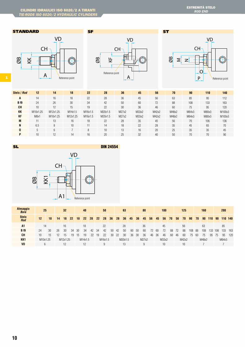
CILINDRI IDRAULICI ISO 6020/2 A tIRANtItIE-RODS ISO 6020/2 HYDRAULIC CYLINDERS
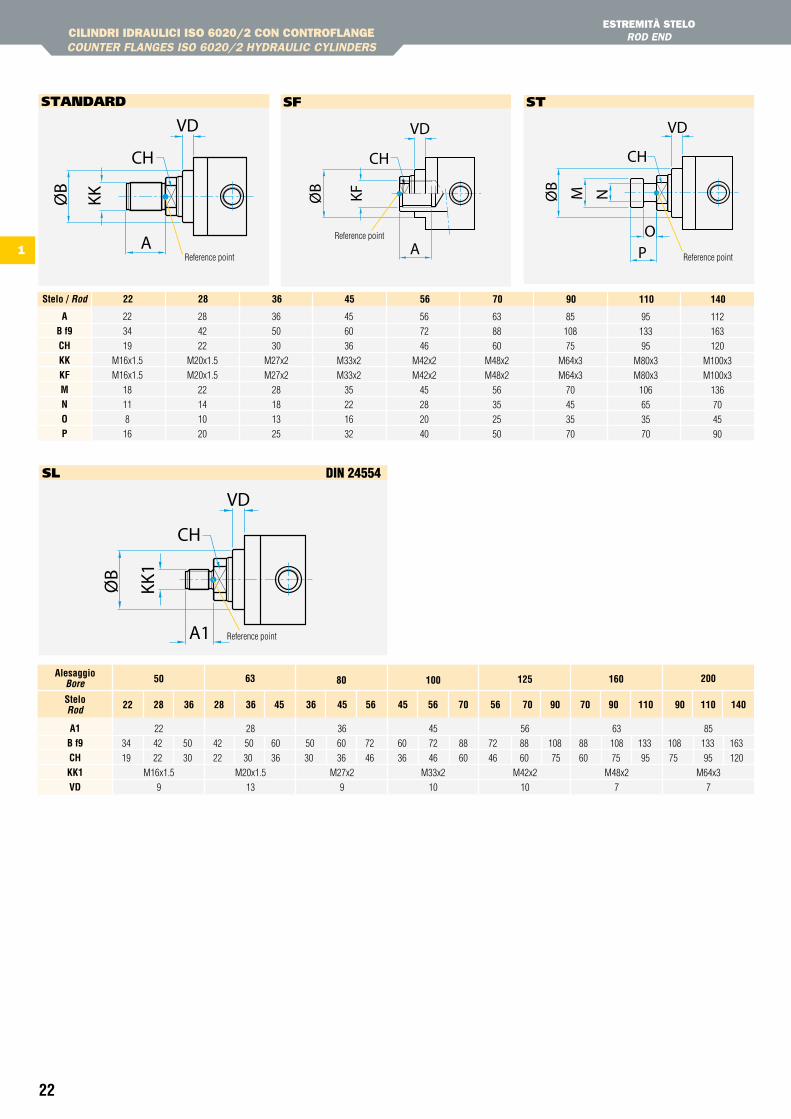
EStREMItà StELOROD END
aB f9ChKKKFMnOP
14
24
10
M10x1.25
M8x1
11
6.5
5
10
12stelo / Rod
16
26
12
M12x1.25
M10x1.25
13
8
6
12
14
18
30
15
M14x1.5
M12x1.25
16
10
7
14
18
22
34
19
M16x1.5
M16x1.5
18
11
8
16
22
28
42
22
M20x1.5
M20x1.5
22
14
10
20
28
36
50
30
M27x2
M27x2
28
18
13
25
36
45
60
36
M33x2
M33x2
35
22
16
32
45
56
72
46
M42x2
M42x2
45
28
20
40
56
63
88
60
M48x2
M48x2
56
35
25
50
70
85
108
75
M64x3
M64x3
70
45
35
70
90
95
133
95
M80x3
M80x3
106
65
35
70
110
112
163
120
M100x3
M100x3
136
70
45
90
140
Reference point
sF
Reference point
sl dIn 24554
sTAnDARD
Reference point Reference point
sT
a1B f9ChKK1VD
14
24 30
10 15
M10x1.25
6
16
26 30 34
12 15 19
M12x1.25
12
18
30 34 42
15 19 22
M14x1.5
12
22
34 42 50
19 22 30
M16x1.5
9
28
42 50 60
22 30 36
M20x1.5
13
36
50 60 72
30 36 46
M27x2
9
45
60 72 88
36 46 60
M33x2
10
56
72 88 108
46 60 75
M42x2
10
63
88 108 133
60 75 95
M48x2
7
85
108 133 163
75 95 120
M64x3
7
25
12
32 40 50 63 80 100 125 160 200alesaggioBore
steloRod
18 14 18 22 18 22 28 22 28 36 28 36 45 36 45 56 45 56 70 56 70 90 70 90 110 90 110 140
11
1
CILINDRI IDRAULICI ISO 6020/2 A tIRANtItIE-RODS ISO 6020/2 HYDRAULIC CYLINDERS
CODICE DI ORDINAzIONEORDERING CODE
ancoraggioMounting
CODiCe OrDinaZiOne / OrDerinG CODe
esecuzione speciale / Special version (1) sX
MX5
ME5
ME6
MS2
MP5
MP3
MP1
MT1
MT4
MT2
MX1
MX3
MX2
MX6
Fori filettati frontali Front tapped holes
Flangia anteriore Front flange
Flangia posteriore Rear flange
Piedini Feet
Cerniera con snodo Ball jointed eye
Cerniera maschio Male clevis
Cerniera femmina Female clevis
Perni anteriori Front trunnions
Perni intermedi Intermediate trunnions
Perni posteriori Rear trunnions
Tiranti prolungati ant. e post. Extended front and rear tie-rods
Tiranti prolungati anteriori Extended front tie-rods
Tiranti prolungati posteriori Extended rear tie-rods
Fori filettati posteriori Rear threaded holes
X
a
B
e
D
C
M
G
h
L
Q
r
s
t
isO 6020/2 Din24554
ME5
ME6
MS2
MP5
MT4
28
eventuale 2° stelo / possible 2nd rod
CD 50 A 500
Corsa / Stroke
Indicare in mm / Specify in mm
/ /
(2)
stelo / Rod
CD
DK
25
32
40
50
63
80
100
125
160
200
1218 1418221822282228362836453645564556705670907090
11090
110140
alesaggio / Bore
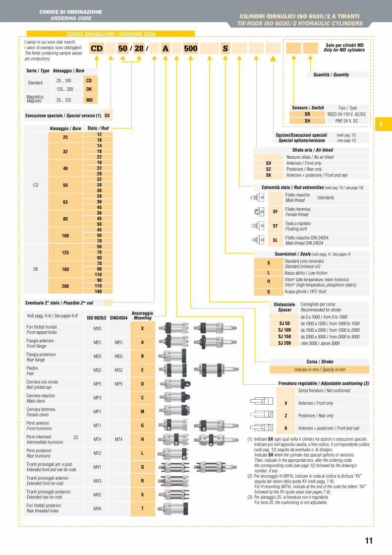
I campi in cui sono stati inseriti i valori di esempio sono obbligatori.The fields containing sample values are compulsory.
(1) Indicare sX ogni qual volta il cilindro ha opzioni o esecuzioni speciali.Indicare poi nell’apposita casella, a fine codice, il corrispondente codice (vedi pag. 12) seguito da eventuale n. di disegno.
Indicate SX when the cylinder has special options or versions. Then, indicate in the appropriate box, after the ordering code, the corresponding code (see page 12) followed by the drawing’s number, if any.(2) Per ancoraggio H (MT4), indicare in coda al codice la dicitura “XV” seguita dal valore della quota XV (vedi pagg. 7-8). For H mounting (MT4), indicate at the end of the code the letters “XV” followed by the XV quote value (see pages 7-8).(3) Per alesaggio 25, la frenatura non è regolabile. For bore 25, the cushioning is not adjustable.
DistanzialeSpacer
sJ 50sJ 100sJ 150sJ 200
da 0 a 1000 / from 0 to 1000da 1000 a 1500 / from 1000 to 1500da 1500 a 2000 / from 1500 to 2000da 2000 a 3000 / from 2000 to 3000oltre 3000 / above 3000
Consigliato per corse:Recommended for stroke:
Opzioni/esecuzioni speciali Special options/versions
(vedi pag. 12) (see page 12)
serie / type alesaggio / Bore
25... 100 CD
125... 200 DK
Magnetico 25... 125 MDMagnetic
Standard
Frenatura regolabile / adjustable cushioning (3)
V
Z
K
Senza frenatura / Not cushioned
Anteriore / Front only
Posteriore / Rear only
Anteriore + posteriore / Front and rear
Vedi pagg. 6-8 / See pages 6-8
estremità stelo / Rod extremities (vedi pag. 10 / see page 10)
sF
st
sL
Filetto maschio Male thread
Filetto femmina Female thread
Testa a martello Floating joint
Filetto maschio DIN 24554 Male thread DIN 24554
(standard)
solo per cilindri MDonly for MD cylinders
sfiato aria / air bleed
Nessuno sfiato / No air bleedAnteriore / Front onlyPosteriore / Rear onlyAnteriore + posteriore / Front and rear
sVsZsK
Guarnizioni / Seals (vedi pagg. 4 / See pages 4)
Standard (olio minerale) Standard (mineral oil)Basso attrito / Low frictionViton® (alte temperature, esteri fosforici)Viton® (high temperature, phosphoric esters)Acqua glicole / HFC-fluid
s
L
h
G
S
sensore / Switch Tipo / TypeREED 24-110 V. AC/DC
PNP 24 V. DC
srsh
Quantità / Quantity
12
1
CILINDRI IDRAULICI ISO 6020/2 A tIRANtItIE-RODS ISO 6020/2 HYDRAULIC CYLINDERS
OPzIONIOPtIONS
3
1
ee1
ee2
3
1
2
2
4
4
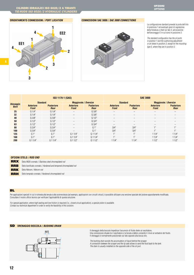
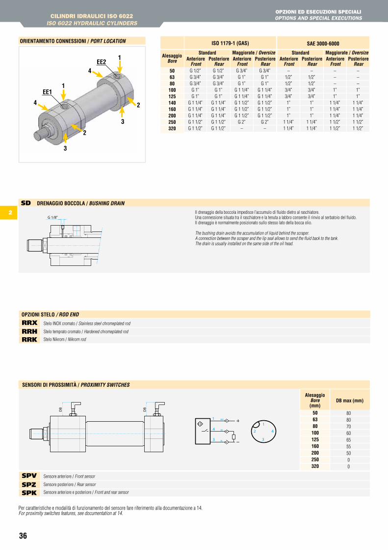
Il drenaggio della boccola impedisce l’accumulo di fluido dietro al raschiatore. Una connessione situata tra il raschiatore e la tenuta a labbro consente il rinvio al serbatoio del fluido. Il drenaggio è normalmente posizionato sul lato opposto alla bocca olio.
The bushing drain avoids the accumulation of liquid behind the scraper. A connection between the scraper and the lip seal allows to send the fluid back to the tank. The drain is usually installed on the opposite side of the oil port.
sD DrenaGGiO BOCCOLa / BuSHinG DRain
La configurazione standard prevede la porta dell’olio in posizione 1 ed eventuali grani di regolazione della frenatura o sfiati sul lato 3, ad eccezione dell’ancoraggio E in cui sono in posizione 2.
The standard configuration has the oil ports in position 1 and the cushioning adjustmentor air bleed in position 3, except for the mountingtype E, where they are in position 2.
Per applicazioni speciali in cui è richiesta alta tenuta e alta scorrevolezza (ad esempio, applicazioni con circuiti chiusi), è possibile utilizzare una versione speciale del pistone appositamente modificata. Consultare il nostro ufficio tecnico per verificare l’applicabilità di questa soluzione.
For special application, where high sealing and low friction is required (i.e., closed circuit application), a special piston is available.Contact our technical department in order to verify the feasibility of this solution.
bl
OrientaMentO COnnessiOni / poRt Location COnnessiOni sae 3000 / Sae 3000 connectionS
253240506380100125160200
alesaggioBore
G 1/4”G 1/4”G 3/8”G 1/2”G 1/2”G 3/4”G 3/4”G 1”G 1”
G 1 1/4”
G 1/4”G 1/4”G 3/8”G 1/2”G 1/2”G 3/4”G 3/4”G 1”G 1”
G 1 1/4”
isO 1179-1 (Gas) sae 3000
–––––––
G 1 1/4”G 1 1/4”G 1 1/2”
G 3/8”G 3/8”G 1/2”G 3/4”G 3/4”G 1”G 1”
G 1 1/4”G 1 1/4”G 1 1/2”
anteriorefront
anteriorefront
–––––
3/4”3/4”1”1”
1 1/4”
–––––
3/4”3/4”1”1”
1 1/4”
standardstandardPosteriore
RearPosteriore
Rearanteriore
frontanteriore
front–––––1”1”
1 1/4”1 1/4”1 1/2”
–––––1”1”
1 1/4”1 1/4”1 1/2”
Maggiorate / oversizeMaggiorate / oversizePosteriore
RearPosteriore
Rear
Stelo INOX cromato / Stainless steel chromeplated rod
Stelo bonificato cromato / Hardened and tempered chromeplated rod
Stelo Nikrom / Nikrom rod
Stelo temprato cromato / Hardened chromeplated rod
RRx RRb RRK RRh
OPZiOni steLO / RoD enD
13
1
25-200
Ba3 Ba5
25-200
Dimensione delle porte / oil port dimension
isO 4401-03nG6
isO 4401-05nG10
Disponibile per alesaggi compresi traAvailable for bore included between
Porta B – lato posteriore / Port B – Rear sideCollegamentiLink
40-125
BV3-a
BV3-B
BV5-a
BV5-B
50-200
Dimensione delle porte / oil port dimension
isO 4401-03nG6
isO 4401-05nG10
Disponibile per alesaggi compresi traAvailable for bore included between
Porta A – lato posteriore / Port A – Rear side
Porta B – lato posteriore / Port B – Rear sideCollegamenti
Link
PIAStRE INCORPORAtE INCORPORAtED PLAtES CILINDRI IDRAULICI ISO 6020/2 A tIRANtI
tIE-RODS ISO 6020/2 HYDRAULIC CYLINDERS
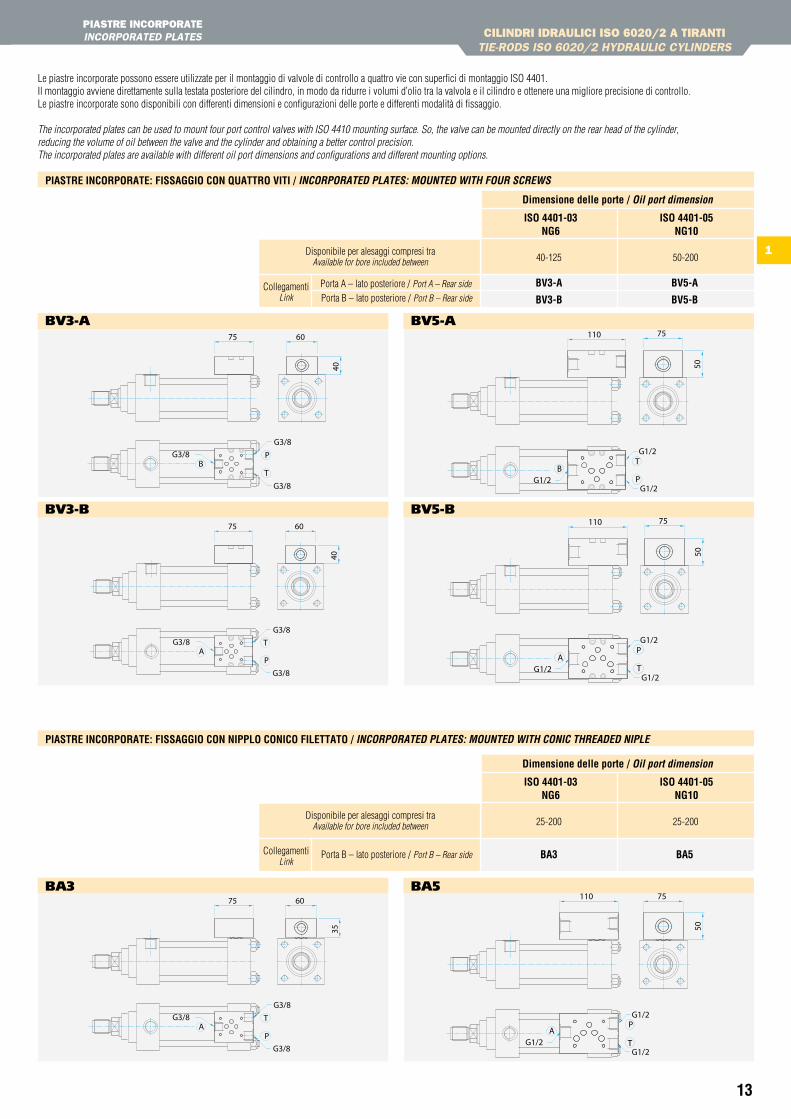
Le piastre incorporate possono essere utilizzate per il montaggio di valvole di controllo a quattro vie con superfici di montaggio ISO 4401.Il montaggio avviene direttamente sulla testata posteriore del cilindro, in modo da ridurre i volumi d’olio tra la valvola e il cilindro e ottenere una migliore precisione di controllo.Le piastre incorporate sono disponibili con differenti dimensioni e configurazioni delle porte e differenti modalità di fissaggio.
The incorporated plates can be used to mount four port control valves with ISO 4410 mounting surface. So, the valve can be mounted directly on the rear head of the cylinder,reducing the volume of oil between the valve and the cylinder and obtaining a better control precision.The incorporated plates are available with different oil port dimensions and configurations and different mounting options.
Piastre inCOrPOrate: FissaGGiO COn QuattrO Viti / incoRpoRateD pLateS: MounteD witH fouR ScRewS
Piastre inCOrPOrate: FissaGGiO COn niPPLO COniCO FiLettatO / incoRpoRateD pLateS: MounteD witH conic tHReaDeD nipLe
bv3-A
bv3-b
bA3
bv5-A
bv5-b
bA5
G3/8
G3/8G3/8
75 6040
BP
T
G3/8G3/8
G3/8
T
PA
40
6075
G3/8
G3/8G3/8
75 60
35
AP
T
G1/2G1/2
G1/2
50
75110
BT
P
T
PA
110 75
50
G1/2
G1/2G1/2
P
50
75110
ATG1/2
G1/2
G1/2
14
185
80
80
70
60
65
55
50
40506380100125160200
DB
DB
BL
BK
BW1
4
3
1
2
3
4
alesaggioBore(mm)
DB max (mm)
sensOri Di PrOssiMità / pRoXiMitY SwitcHeS
CILINDRI IDRAULICI ISO 6020/2 A tIRANtItIE-RODS ISO 6020/2 HYDRAULIC CYLINDERS
SENSORI DI PROSSIMItàPROXIMItY SWItCHES
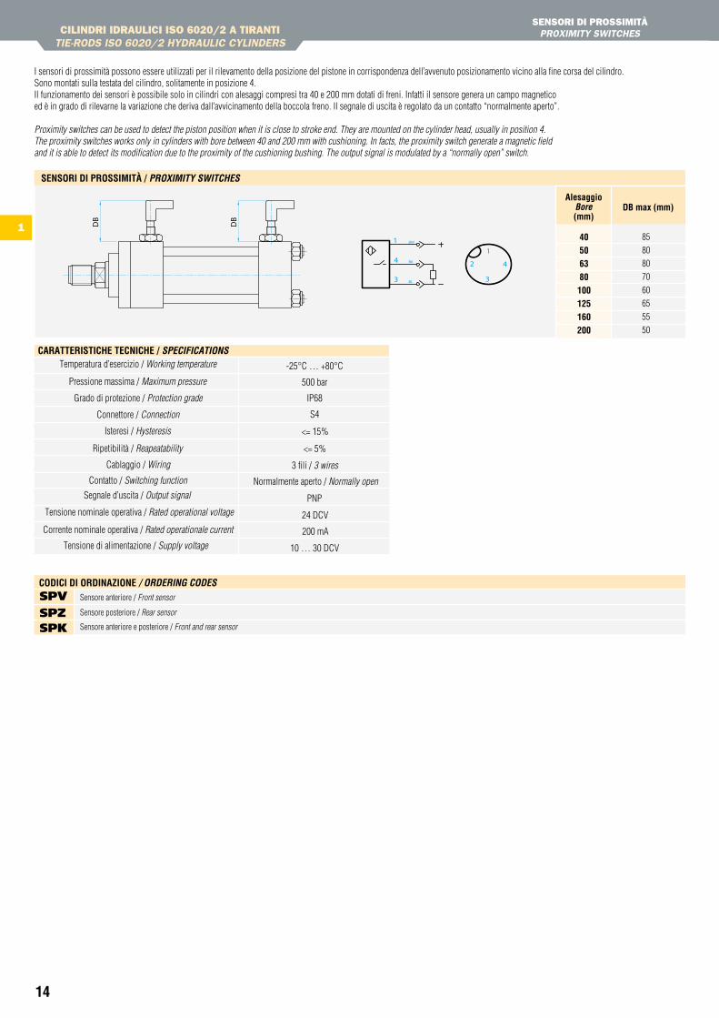
I sensori di prossimità possono essere utilizzati per il rilevamento della posizione del pistone in corrispondenza dell’avvenuto posizionamento vicino alla fine corsa del cilindro.Sono montati sulla testata del cilindro, solitamente in posizione 4.Il funzionamento dei sensori è possibile solo in cilindri con alesaggi compresi tra 40 e 200 mm dotati di freni. Infatti il sensore genera un campo magneticoed è in grado di rilevarne la variazione che deriva dall’avvicinamento della boccola freno. Il segnale di uscita è regolato da un contatto “normalmente aperto”. Proximity switches can be used to detect the piston position when it is close to stroke end. They are mounted on the cylinder head, usually in position 4.The proximity switches works only in cylinders with bore between 40 and 200 mm with cushioning. In facts, the proximity switch generate a magnetic fieldand it is able to detect its modification due to the proximity of the cushioning bushing. The output signal is modulated by a “normally open” switch.
Temperatura d’esercizio / Working temperature
Pressione massima / Maximum pressure
Grado di protezione / Protection grade
Connettore / Connection
Isteresi / Hysteresis
Ripetibilità / Reapeatability
Cablaggio / Wiring
Contatto / Switching function
Segnale d’uscita / Output signal
Tensione nominale operativa / Rated operational voltage
Corrente nominale operativa / Rated operationale current
Tensione di alimentazione / Supply voltage
-25°C … +80°C
500 bar
IP68
S4
<= 15%
<= 5%
3 fili / 3 wires
Normalmente aperto / Normally open
PNP
24 DCV
200 mA
10 … 30 DCV
CaratteristiChe teCniChe / SpecificationS
Sensore anteriore / Front sensor
Sensore posteriore / Rear sensor
Sensore anteriore e posteriore / Front and rear sensor
sPv sPZ sPK
CODiCi Di OrDinaZiOne / oRDeRinG coDeS
15
1
StAffE PER SENSORI MAgNEtICI / BRACkEt FOR MAGNEtIC PROXIMItY SWItCHES
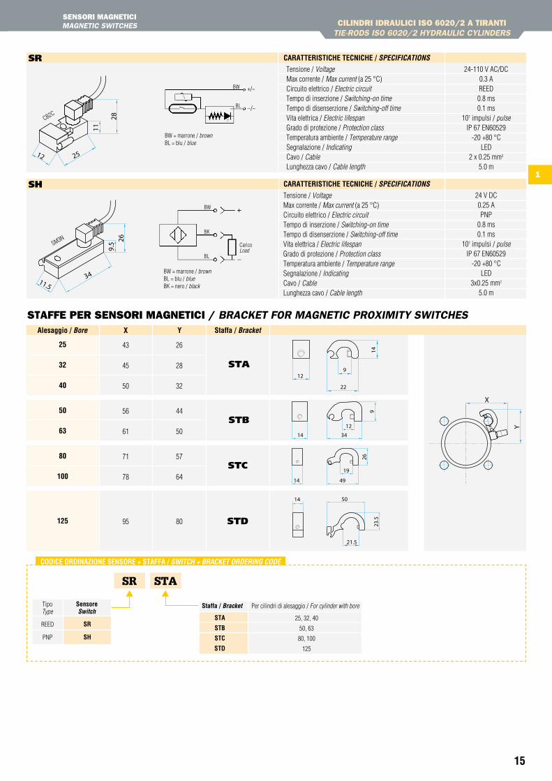
Tensione / VoltageMax corrente / Max current (a 25 °C)Circuito elettrico / Electric circuitTempo di inserzione / Switching-on timeTempo di disenserzione / Switching-off timeVita elettrica / Electric lifespanGrado di protezione / Protection classTemperatura ambiente / Temperature rangeSegnalazione / IndicatingCavo / CableLunghezza cavo / Cable length
BW = marrone / brownBL = blu / blue
CB2C
BW
BL
24-110 V AC/DC0.3 AREED
0.8 ms0.1 ms
107 impulsi / pulseIP 67 EN60529
-20 +80 °CLED
2 x 0.25 mm2
5.0 m
Tensione / VoltageMax corrente / Max current (a 25 °C)Circuito elettrico / Electric circuitTempo di inserzione / Switching-on timeTempo di disenserzione / Switching-off timeVita elettrica / Electric lifespanGrado di protezione / Protection classTemperatura ambiente / Temperature rangeSegnalazione / IndicatingCavo / CableLunghezza cavo / Cable length
24 V DC0.25 APNP
0.8 ms0.1 ms
107 impulsi / pulseIP 67 EN60529
-20 +80 °CLED
3x0.25 mm2
5.0 m
CaricoLoad
BW
BK
BL
BW = marrone / brownBL = blu / blueBK = nero / black
SR STA
Tipo Type
sensore Switch
REED
PNP
sr
sh
CODiCe OrDinaZiOne sensOre + staFFa / SwitcH + BRacket oRDeRinG coDe
staffa / Bracket Per cilindri di alesaggio / For cylinder with bore
sta
stB
stC
stD
25, 32, 40
50, 63
80, 100
125
25
32
40
50
63
80
100
125
sTA
sTb
sTC
sTD
26
28
32
44
50
57
64
80
43
45
50
56
61
71
78
95
alesaggio / Bore X Y staffa / Bracket
sR
sh
CaratteristiChe teCniChe / SpecificationS
CaratteristiChe teCniChe / SpecificationS
SM3N
SENSORI MAgNEtICIMAGNEtIC SWItCHES CILINDRI IDRAULICI ISO 6020/2 A tIRANtI
tIE-RODS ISO 6020/2 HYDRAULIC CYLINDERS
+/~
–/~
16
1
CILINDRI IDRAULICI ISO 6020/2 CON CONtROfLANgECOUNtER FLANGES ISO 6020/2 HYDRAULIC CYLINDERS
CARAttERIStICHE tECNICHEtECHNICAL CHARACtERIStICS
hD/hK
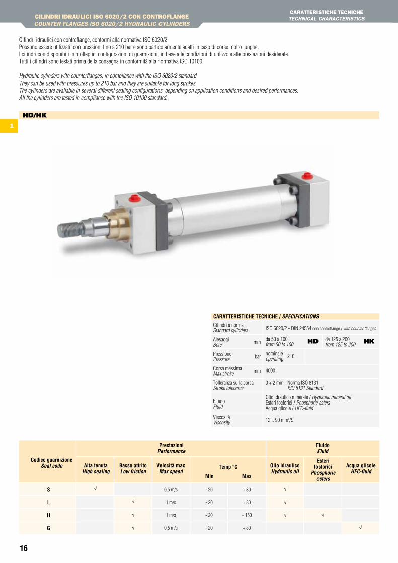
Cilindri idraulici con controflange, conformi alla normativa ISO 6020/2.Possono essere utilizzati con pressioni fino a 210 bar e sono particolarmente adatti in caso di corse molto lunghe. I cilindri con disponibili in molteplici configurazioni di guarnizioni, in base alle condizioni di utilizzo e alle prestazioni desiderate.Tutti i cilindri sono testati prima della consegna in conformità alla normativa ISO 10100.
Hydraulic cylinders with counterflanges, in compliance with the ISO 6020/2 standard. They can be used with pressures up to 210 bar and they are suitable for long strokes.The cylinders are available in several different sealing configurations, depending on application conditions and desired performances.All the cylinders are tested in compliance with the ISO 10100 standard.
Cilindri a norma Standard cylinders
Alesaggi mm Bore
Pressione barPressure
Corsa massima mmMax stroke
Tolleranza sulla corsa Stroke tolerance
Fluido Fluid Viscosità Viscosity
ISO 6020/2 - DIN 24554 con controflange / with counter flanges
da 50 a 100 from 50 to 100
nominale 210operating
4000 0 + 2 mm Norma ISO 8131 ISO 8131 Standard
Olio idraulico minerale / Hydraulic mineral oil Esteri fosforici / Phosphoric estersAcqua glicole / HFC-fluid
12... 90 mm2/S
CaratteristiChe teCniChe / SpecificationS
hD hKda 125 a 200 from 125 to 200
0,5 m/s
1 m/s
1 m/s
0,5 m/s
- 20
- 20
- 20
- 20
+ 80
+ 80
+ 150
+ 80
Codice guarnizioneSeal code alta tenuta
High sealingOlio idraulicoHydraulic oil
esterifosforici
phosphoric esters
acqua glicoleHfc-fluid
Basso attritoLow friction
Velocità maxMax speed
temp °C
Min Max
Prestazioniperformance
Fluidofluid
s L h G
√
√
√
√
√
√
√ √
√
17
1
CILINDRI IDRAULICI ISO 6020/2 CON CONtROfLANgECOUNtER FLANGES ISO 6020/2 HYDRAULIC CYLINDERS
76 42 12983
211815 1819 2014
4 5
17 16
10 13
CARAttERIStICHE tECNICHEtECHNICAL CHARACtERIStICS
s L h GCava / GrooveComponente / component
Materiale / Material
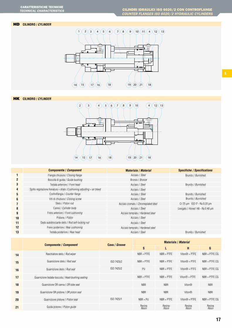
Raschiatore stelo / Rod wiper
Guarnizione stelo / Rod seal
Guarnizione OR pistone / OR piston seal
Guarnizione stelo / Rod seal ISO 7425/2
NBR + PTFE NBR + PTFE NBR + PTFE CGViton® + PTFE
NBR + PTFE NBR + PTFE NBR + PTFE CGViton® + PTFE
PU NBR + PTFE NBR + PTFE CGViton® + PTFE
Viton® + PTFE
NBR
NBR + PTFE
NBR
NBR + PTFE
NBR
NBR + PTFE CG
Viton®
NBR NBR NBRViton®
NBR + PU NBR + PTFE NBR + PTFE CGViton® + PTFE
ISO 7425/2
ISO 7425/1
Guarnizione OR canna / OR tube seal
Guarnizione testata-boccola / Head-bushing sealing
Guarnizione pistone / Piston seal
Guida pistone / Piston guide ResinaResin
ResinaResin
ResinaResin
ResinaResin
Materiale / Material spec.Componente / componentFlangia chiusura / Closing flange
Bronzo / BronzeBoccola di guida / Guide bushing
Testata anteriore / Front head
Spillo regolazione frenatura + sfiato /Cushioning adjusting + air bleed
Brunito / Burnished
Levigato / Honed H8 - Ra 0.40 µm
Brunito / Burnished
Cr 25 µm ISO f7 - Ra 0.20 µm
Viti di chiusura / Closing screw
Stelo / Piston rod
Canna / Cylinder body
Pistone / Piston
Dado autobloccante stelo / Rod self-locking nut
Freno anteriore / Front cushioning
Freno posteriore / Rear cushioning
Testata posteriore / Rear head
Acciaio / Steel Brunito / Burnished
Acciaio / Steel Brunito / Burnished
Acciaio / Steel
Acciaio / Steel
Acciaio / Steel
Acciaio cromato / Chromeplated steel
Acciaio / Steel
Acciaio / Steel
Acciaio temprato / Hardened steel
Acciaio / Steel
Acciaio temprato / Hardened steel
Acciaio / Steel Brunito / Burnished
12
3
4
5
6
78
9
10
1112
13
Materiale / Material specifiche / SpecificationsComponente / component
Controflangia / Counter flange
1 3 4 7 8 10
14
9
2019
2 4
18
6 12115 13
15 18 2117 16
hD CiLinDrO / cYLinDeR
hK CiLinDrO / cYLinDeR
14
15
16
17
18
19
20
21
18
1
CILINDRI IDRAULICI ISO 6020/2 CON CONtROfLANgECOUNtER FLANGES ISO 6020/2 HYDRAULIC CYLINDERS
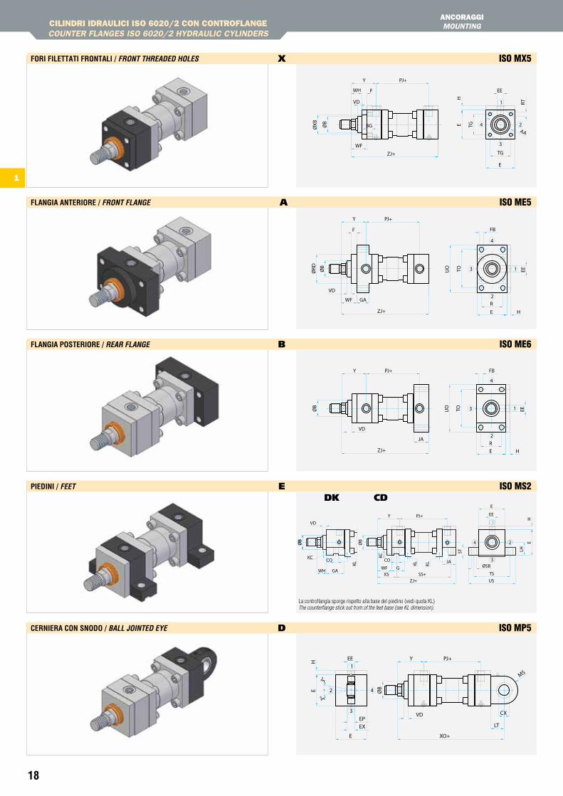
FOri FiLettati FrOntaLi / fRont tHReaDeD HoLeS x ISO MX5
FLanGia anteriOre / fRont fLanGe A ISO ME5
FLanGia POsteriOre / ReaR fLanGe b ISO ME6
PieDini / feet e ISO MS2
Cerniera COn snODO / BaLL JointeD eYe D ISO MP5
DK CD
ANCORAggIMOUNtING
VD
WH
ØXB BG
1
3
4 2AA
RT
HE TG
WFTG
E
ZJ+
ØB
EEF
Y PJ+
EETOUO
FBF
Y PJ+
ØRD
GAWF
H
R
EZJ+
3
2
1
4
ØB
VD
4
3 1
2JA
ZJ+ HER
Y PJ+ FB
TOUO EEØB
VD
1
4
3
2
YEE PJ+
EH
E
EXEP
XO+
LT
CX
MS
ØB
VD
3°3°
PJ+Y
H
E
EE
E
LH
US
ØSB
TSSS+
JA
ZJ+
GXS
WF
ST
24
3
1
GAWH
COCOKC
ØB
VD
KC
KL KLKL
ØB
ØB
La controflangia sporge rispetto alla base del piedino (vedi quota KL)The counterflange stick out from of the feet base (see KL dimension).
19
1
CILINDRI IDRAULICI ISO 6020/2 CON CONtROfLANgECOUNtER FLANGES ISO 6020/2 HYDRAULIC CYLINDERS
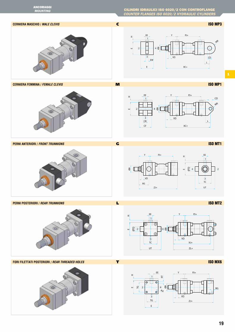
Perni anteriOri / fRont tRunnionS g ISO MT1
Perni POsteriOri / ReaR tRunnionS l ISO MT2
FOri FiLettati POsteriOri / ReaR tHReaDeD HoLeS T ISO MX6
Cerniera MasChiO / MaLe cLeViS C ISO MP3
Cerniera FeMMina / feMaLe cLeViS M ISO MP1
ANCORAggIMOUNtING
MR
CD
L
XC+
EW
E
HE
PJ+EE Y
2
3
4
1
ØB
VD
1
4
3
2
YEE PJ+
EH
XC+CF
CB L
CD
MR
ØB
VD
24
3
1
PJ+Y EEH
ZJ+
XG
UT
TCE ØTDØB
VD
2 4
3
1
YEE
RT
PJ+
E TG
H
E
TG
AA
ZJ+
BGØB
VD
4
3
2
1
EE PJ+Y
E ØTD
H
UT
TC XJ+
ZL+
ØB
VD
20
1
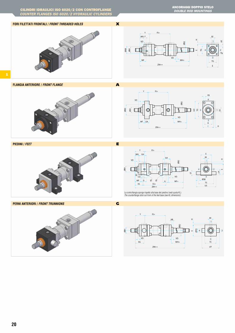
CILINDRI IDRAULICI ISO 6020/2 CON CONtROfLANgECOUNtER FLANGES ISO 6020/2 HYDRAULIC CYLINDERS
ANCORAggI DOPPIO StELO DOUBLE ROD MOUNtINGS
PieDini / feet e
FLanGia anteriOre / fRont fLanGe A
Perni anteriOri / fRont tRunnionS g
FOri FiLettati FrOntaLi / fRont tHReaDeD HoLeS x
VD
ØXB ØB1
WH
BG
1
3
4 2AA
RT
EE
HE TG
TG
E
WH+WF
ZM++
F
PJ+Y
VD
ØB2
EETOUO
FB
WF GA
H
R
E
WH+
ZM++Ø
RD
Y PJ+
3
2
1
4
VD
ØB2
ØB1
VD
GA
G
1
3
4 2
WH
HE
LHST
TSUS
ØSBWF+WF
XS
G
SS+ZM++
EE
EGA
Y PJ+
CO
KC
VDØ
B2
ØB1
VD
KL KL
ØTDE
TC
UT
WH+XG
ZM++
PJ+Y
EEH
1
3
4 2
KB
VD
ØB2
ØB1
VD
La controflangia sporge rispetto alla base del piedino (vedi quota KL)The counterflange stick out from of the feet base (see KL dimension).
21
1
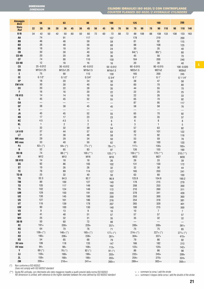
CILINDRI IDRAULICI ISO 6020/2 CON CONtROfLANgECOUNtER FLANGES ISO 6020/2 HYDRAULIC CYLINDERS
DIMENSIONIDIMENSION
(*) Non conforme a ISO 6020/2 Does not comply with ISO 6020/2 standard
(**) Quota RD unificata, con riferimento allo stelo maggiore rispetto a quelli previsti dalla norma ISO 6020/2 RD dimension is unified, with reference to the higher diameter between the ones defined by ISO 6020/2 standard
+ = sommare la corsa / add the stroke++ = sommare il doppio della corsa / add the double of the stroke
aaBBBDBGCB
CD h9CF
CO h8CXDDeeeeP
eW h14eXF
FB h13G
GaGFhJaKBKCKLL
Lh h10Lt
Mr maxMs max
PJr
rD f8rt
sB h13sssttC
tD f8tGtMtOtsuMuOusutuWVDWFWh
XB f9XCXGXJXOXs
XV minXV max
YZJZLZM
B f9
7446381830207412
25 -0.012M12x1.25
75G 1/2”
183020161445—38—45174.513237312933
62+ (*)5274
M121492197625
52.389105102129130127116909412550
191+64
136+ (*)190+5410694+
69 (*)159+159+200++
9146481830209016
30 -0.012M12x1.25
90G 1/2”
203022161445—38—45174.523244382940
64+ (*)65
88 (**)M121886268932
64.310011712415014516113910013483260
200+70
146+ (*)206+6511898+
76 (*)168+168+216++
117595824402811016
40 -0.012M16x1.5
115G 3/4”
244028201852—45—5223523957483450
77+ (*)83
105 (**)M16181052611440
82.71271491491911801861781309513172
229+76
165+ (*)238+68133108+82 (*)190+190+241++
137596824503613016
50 -0.012M16x1.5
130G 3/4”
305035221855—45—5523665463585062
78+ (*)97
125 (**)M16261023212750
96.914016217222020021620714010573588
257+71
177+ (*)261+79147113+91 (*)203+203+260++
178818830
64(*)4516420
60 -0.015M22x1.5
165G 1”3860442222658758—6530635782725380
117+126
150 (**)M22261313216563
125.9178208210278250254265180105735 —
289+75
214+ (*)304+79166123+86
232+254+289++
2199210835
80(*)5620030
80 -0.015M27x2
200G 1”4770552526709558—703581631019259100130+155
170 (**)M27331303820380
154.921525326034130031832921575732—
308+75
227+ (*)337+86182120+86
245+270+302++
26911512540807024040
100 -0.020M30x2
245G 1 1/4”
58807025339211776—9237858212211678120165+190
210 (**)M303917244241100
190.227930031143936038140130075732—
381+85
271+ (*)415+92213142+98
299+324+356++
50 63 80 100 125 160 200alesaggioBore
steloRod 22 28 36
34 42 50
28 36 45
42 50 60
36 45 56
50 60 72
45 56 70
60 72 88
56 70 90
72 88 108
70 90 110
88 108 133
90 110 140
108 133 163
22
1
CILINDRI IDRAULICI ISO 6020/2 CON CONtROfLANgECOUNtER FLANGES ISO 6020/2 HYDRAULIC CYLINDERS
EStREMItà StELOROD END
aB f9ChKKKFMnOP
stelo / Rod
22
34
19
M16x1.5
M16x1.5
18
11
8
16
22
28
42
22
M20x1.5
M20x1.5
22
14
10
20
28
36
50
30
M27x2
M27x2
28
18
13
25
36
45
60
36
M33x2
M33x2
35
22
16
32
45
56
72
46
M42x2
M42x2
45
28
20
40
56
63
88
60
M48x2
M48x2
56
35
25
50
70
85
108
75
M64x3
M64x3
70
45
35
70
90
95
133
95
M80x3
M80x3
106
65
35
70
110
112
163
120
M100x3
M100x3
136
70
45
90
140
Reference point
sF
Reference point
sl dIn 24554
sTAnDARD
Reference point Reference point
sT
a1B f9ChKK1VD
22
34 42 50
19 22 30
M16x1.5
9
28
42 50 60
22 30 36
M20x1.5
13
36
50 60 72
30 36 46
M27x2
9
45
60 72 88
36 46 60
M33x2
10
56
72 88 108
46 60 75
M42x2
10
63
88 108 133
60 75 95
M48x2
7
85
108 133 163
75 95 120
M64x3
7
50 63 80 100 125 160 200alesaggioBore
steloRod
22 28 36 28 36 45 36 45 56 45 56 70 56 70 90 70 90 110 90 110 140
23
1
CILINDRI IDRAULICI ISO 6020/2 CON CONtROfLANgECOUNtER FLANGES ISO 6020/2 HYDRAULIC CYLINDERS
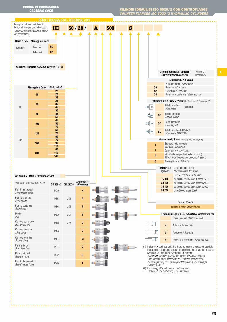
CODICE DI ORDINAzIONEORDERING CODE
ancoraggioMounting
CODiCe OrDinaZiOne / OrDerinG CODe
esecuzione speciale / Special version (1) sX
MX5
ME5
ME6
MS2
MP5
MP3
MP1
MT1
MT2
MX6
Fori filettati frontali Front tapped holes
Flangia anteriore Front flange
Flangia posteriore Rear flange
Piedini Feet
Cerniera con snodo Ball jointed eye
Cerniera maschio Male clevis
Cerniera femmina Female clevis
Perni anteriori Front trunnions
Perni posteriori Rear trunnions
Fori filettati posteriori Rear threaded holes
X
a
B
e
D
C
M
G
L
t
isO 6020/2 Din24554
ME5
ME6
MS2
MP5
28
eventuale 2° stelo / possible 2nd rod
HD 50 A 500
Corsa / Stroke
Indicare in mm / Specify in mm
/ /
stelo / Rod
HD
HK
50
63
80
100
125
160
200
2228362836453645564556705670907090
11090
110140
alesaggio / Bore
sfiato aria / air bleed
Nessuno sfiato / No air bleedAnteriore / Front onlyPosteriore / Rear onlyAnteriore + posteriore / Front and rear
Frenatura regolabile / adjustable cushioning (2)
V
Z
K
Senza frenatura / Not cushioned
Anteriore / Front only
Posteriore / Rear only
Anteriore + posteriore / Front and rear
I campi in cui sono stati inseriti i valori di esempio sono obbligatori.The fields containing sample values are compulsory.
(1) Indicare sX ogni qual volta il cilindro ha opzioni o esecuzioni speciali.Indicare poi nell’apposita casella, a fine codice, il corrispondente codice (vedi pag. 24) seguito da eventuale n. di disegno.
Indicate SX when the cylinder has special options or versions. Then, indicate in the appropriate box, after the ordering code, the corresponding code (see page 24) followed by the drawing’s number, if any.(2) Per alesaggio 25, la frenatura non è regolabile. For bore 25, the cushioning is not adjustable.
DistanzialeSpacer
sJ 50sJ 100sJ 150sJ 200
da 0 a 1000 / from 0 to 1000da 1000 a 1500 / from 1000 to 1500da 1500 a 2000 / from 1500 to 2000da 2000 a 3000 / from 2000 to 3000oltre 3000 / above 3000
Consigliato per corse:Recommended for stroke:
Opzioni/esecuzioni speciali Special options/versions
(vedi pag. 24) (see page 24)
serie / type alesaggio / Bore
50... 100 hD
125... 200 hKStandard
Vedi pagg. 18-20 / See pages 18-20
estremità stelo / Rod extremities (vedi pag. 22 / see page 22)
sF
st
sL
Filetto maschio Male thread
Filetto femmina Female thread
Testa a martello Floating joint
Filetto maschio DIN 24554 Male thread DIN 24554
(standard)
Guarnizioni / Seals (vedi pag. 16 / see page 16)
Standard (olio minerale) Standard (mineral oil)Basso attrito / Low frictionViton® (alte temperature, esteri fosforici)Viton® (high temperature, phosphoric esters)Acqua glicole / HFC-fluid
sVsZsK
s
L
h
G
S
24
Per applicazioni speciali in cui è richiesta alta tenuta e alta scorrevolezza (ad esempio, applicazioni con circuiti chiusi), è possibile utilizzare una versione speciale del pistone appositamente modificata. Consultare il nostro ufficio tecnico per verificare l’applicabilità di questa soluzione.
For special application, where high sealing and low friction is required (i.e., closed circuit application), a special piston is available.Contact our technical department in order to verify the feasibility of this solution.
bl
CILINDRI IDRAULICI ISO 6020/2 CON CONtROfLANgECOUNtER FLANGES ISO 6020/2 HYDRAULIC CYLINDERS
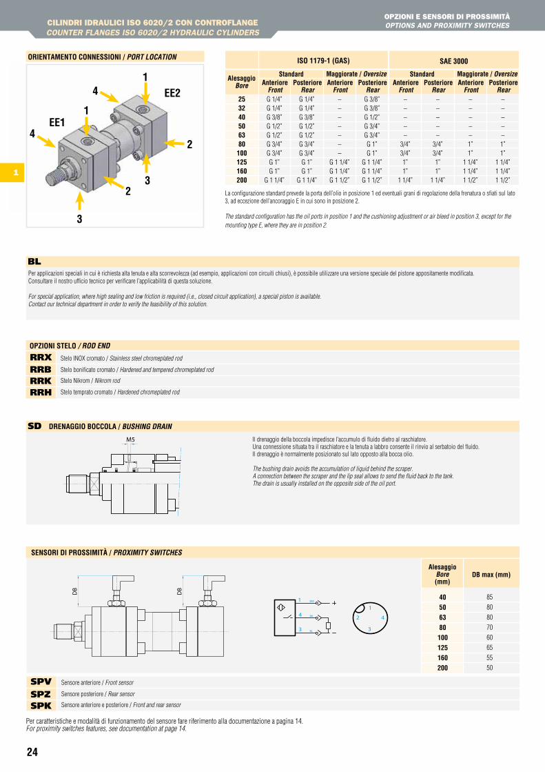
OPzIONI E SENSORI DI PROSSIMItà OPtIONS AND PROXIMItY SWItCHES
3
1
ee1
ee2
3
1
2
2
4
4253240506380100125160200
alesaggioBore anteriore
frontG 1/4”G 1/4”G 3/8”G 1/2”G 1/2”G 3/4”G 3/4”G 1”G 1”
G 1 1/4”
G 1/4”G 1/4”G 3/8”G 1/2”G 1/2”G 3/4”G 3/4”G 1”G 1”
G 1 1/4”
standardPosteriore
Rear
isO 1179-1 (Gas) sae 3000
anteriorefront
–––––––
G 1 1/4”G 1 1/4”G 1 1/2”
G 3/8”G 3/8”G 1/2”G 3/4”G 3/4”G 1”G 1”
G 1 1/4”G 1 1/4”G 1 1/2”
Maggiorate / oversizePosteriore
Rearanteriore
front–––––
3/4”3/4”1”1”
1 1/4”
–––––
3/4”3/4”1”1”
1 1/4”
standardPosteriore
Rearanteriore
front–––––1”1”
1 1/4”1 1/4”1 1/2”
–––––1”1”
1 1/4”1 1/4”1 1/2”
Maggiorate / oversizePosteriore
Rear
M5 Il drenaggio della boccola impedisce l’accumulo di fluido dietro al raschiatore. Una connessione situata tra il raschiatore e la tenuta a labbro consente il rinvio al serbatoio del fluido. Il drenaggio è normalmente posizionato sul lato opposto alla bocca olio.
The bushing drain avoids the accumulation of liquid behind the scraper. A connection between the scraper and the lip seal allows to send the fluid back to the tank. The drain is usually installed on the opposite side of the oil port.
sD DrenaGGiO BOCCOLa / BuSHinG DRain
Per caratteristiche e modalità di funzionamento del sensore fare riferimento alla documentazione a pagina 14.For proximity switches features, see documentation at page 14.
85
80
80
70
60
65
55
50
40506380100125160200
BL
BK
BW1
4
3
1
2
3
4
alesaggioBore(mm)
DB max (mm)
sensOri Di PrOssiMità / pRoXiMitY SwitcHeS
DB
DB
Sensore anteriore / Front sensor
Sensore posteriore / Rear sensor
Sensore anteriore e posteriore / Front and rear sensor
sPv sPZ sPK
OrientaMentO COnnessiOni / poRt Location
1
La configurazione standard prevede la porta dell’olio in posizione 1 ed eventuali grani di regolazione della frenatura o sfiati sul lato 3, ad eccezione dell’ancoraggio E in cui sono in posizione 2.
The standard configuration has the oil ports in position 1 and the cushioning adjustment or air bleed in position 3, except for the mounting type E, where they are in position 2.
Stelo INOX cromato / Stainless steel chromeplated rod
Stelo bonificato cromato / Hardened and tempered chromeplated rod
Stelo Nikrom / Nikrom rod
Stelo temprato cromato / Hardened chromeplated rod
RRx RRb RRK RRh
OPZiOni steLO / RoD enD
25
1
CILINDRI IDRAULICI ISO 6020/2 CON CONtROfLANgECOUNtER FLANGES ISO 6020/2 HYDRAULIC CYLINDERS
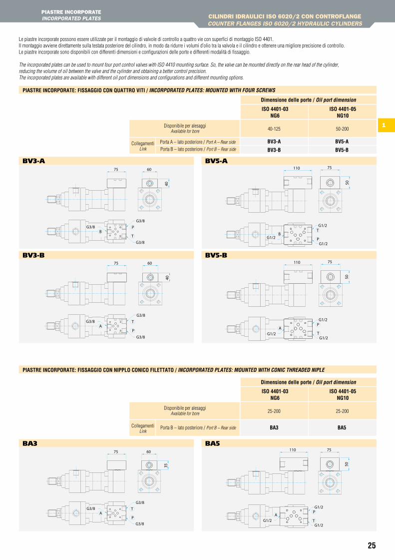
PIAStRE INCORPORAtE INCORPORAtED PLAtES
Le piastre incorporate possono essere utilizzate per il montaggio di valvole di controllo a quattro vie con superfici di montaggio ISO 4401.Il montaggio avviene direttamente sulla testata posteriore del cilindro, in modo da ridurre i volumi d’olio tra la valvola e il cilindro e ottenere una migliore precisione di controllo.Le piastre incorporate sono disponibili con differenti dimensioni e configurazioni delle porte e differenti modalità di fissaggio.
The incorporated plates can be used to mount four port control valves with ISO 4410 mounting surface. So, the valve can be mounted directly on the rear head of the cylinder,reducing the volume of oil between the valve and the cylinder and obtaining a better control precision.The incorporated plates are available with different oil port dimensions and configurations and different mounting options.
25-200
Ba3 Ba5
25-200
Dimensione delle porte / oil port dimension
isO 4401-03nG6
isO 4401-05nG10
Disponibile per alesaggiAvailable for bore
Porta B – lato posteriore / Port B – Rear sideCollegamentiLink
40-125
BV3-a
BV3-B
BV5-a
BV5-B
50-200
Dimensione delle porte / oil port dimension
isO 4401-03nG6
isO 4401-05nG10
Disponibile per alesaggiAvailable for bore
Porta A – lato posteriore / Port A – Rear side
Porta B – lato posteriore / Port B – Rear sideCollegamenti
Link
Piastre inCOrPOrate: FissaGGiO COn QuattrO Viti / incoRpoRateD pLateS: MounteD witH fouR ScRewS
Piastre inCOrPOrate: FissaGGiO COn niPPLO COniCO FiLettatO / incoRpoRateD pLateS: MounteD witH conic tHReaDeD nipLe
bv3-A
bv3-b
bA3
bv5-A
bv5-b
bA5
G3/8
G3/8G3/8
75 6040
BP
T
G3/8G3/8
G3/8
T
PA
40
6075
G3/8
G3/8G3/8
75 60
35
AP
T
G1/2G1/2
G1/2
50
75110
BT
P
T
PA
110 75
50
G1/2
G1/2G1/2
P
50
75110
ATG1/2
G1/2
G1/2
26
1
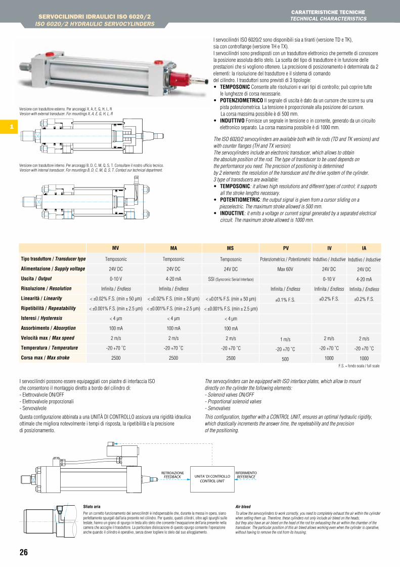
I servocilindri ISO 6020/2 sono disponibili sia a tiranti (versione TD e TK),sia con controflange (versione TH e TX). I servocilindri sono predisposti con un trasduttore elettronico che permette di conoscere la posizione assoluta dello stelo. La scelta del tipo di trasduttore è in funzione delle prestazioni che si vogliono ottenere. La precisione di posizionamento è determinata da 2 elementi: la risoluzione del trasduttore e il sistema di comando del cilindro. I trasduttori sono previsti di 3 tipologie:• teMPOsOniC Consente alte risoluzioni e vari tipi di controllo; può coprire tutte
le lunghezze di corsa necessarie.• POtenZiOMetriCO Il segnale di uscita è dato da un cursore che scorre su una
pista potenziometrica. La tensione è proporzionale alla posizione del cursore. La corsa massima possibile è di 500 mm.• inDuttiVO Fornisce un segnale in tensione o in corrente, generato da un circuito
elettronico separato. La corsa massima possibile è di 1000 mm.
Versione con trasduttore esterno. Per ancoraggi X, A, E, G, H, L, RVersion with external transducer. For mountings X, A, E, G, H, L, R
Versione con trasduttore interno. Per ancoraggi B, D, C, M, Q, S, T. Consultare il nostro ufficio tecnico.Version with internal transducer. For mountings B, D, C, M, Q, S, T. Contact our technical department.
F.S. = fondo scala / full scale
I servocilindri possono essere equipaggiati con piastre di interfaccia ISO che consentono il montaggio diretto a bordo del cilindro di: - Elettrovalvole ON/OFF - Elettrovalvole proporzionali - Servovalvole
Questa configurazione abbinata a una UNITà DI CONTROLLO assicura una rigidità idraulica ottimale che migliora notevolmente i tempi di risposta, la ripetibilità e la precisione di posizionamento.
The servocylinders can be equipped with ISO interface plates, which allow to mount directly on the cylinder the following elements: - Solenoid valves ON/OFF - Proportional solenoid valves - Servovalves
This configuration, together with a CONTROL UNIT, ensures an optimal hydraulic rigidity, which drastically increments the answer time, the repeteability and the precision of the positioning.
sfiato aria
Per un corretto funzionamento dei servocilindri è indispensabile che, durante la messa in opera, siano perfettamente spurgati dall’aria presente nel cilindro. Per questo, questi cilindri, oltre agli spurghi sulle testate, hanno un grano di spurgo in testa allo stelo che consente l’evaquazione dell’aria presente nella camera che accoglie il trasduttore. La particolare dislocazione di questo spurgo consente l’operazione anche quando il cilindro è operativo, senza dover togliere lo stelo dal suo alloggiamento.
air bleed
To allow the servocylinders to work correctly, you need to completely exhaust the air within the cylinder when setting them up. Therefore, these cylinders not only include air bleed on the heads, but they also have an air bleed on the head of the rod for exhausting the air within the chamber of the transducer. The particular position of this air bleed allows working even when the cylinder is operative, without having to remove the rod from its housing.
The ISO 6020/2 servocylinders are available both with tie rods (TD and TK versions) and with counter flanges (TH and TX version).The servocylinders include an electronic transducer, which allows to obtain the absolute position of the rod. The type of transducer to be used depends on the performance you need. The precision of positioning is determined by 2 elements: the resolution of the transducer and the drive system of the cylinder. 3 type of transducers are available:• teMPOsOniC: it allows high resolutions and different types of control; it supports
all the stroke lengths necessary.• POtentiOMetriC: the output signal is given from a cursor sliding on a piezoelectric. The maximum stroke allowed is 500 mm.• inDuCtiVe: it emits a voltage or current signal generated by a separated electrical
circuit. The maximum stroke allowed is 1000 mm.
Temposonic
24V DC
0-10 V
Infinita / Endless
< ±0.02% F.S. (min ± 50 µm)
< ±0.001% F.S. (min ± 2.5 µm)
< 4 µm
100 mA
2 m/s
-20 +70 ˚C
2500
MV
Temposonic
24V DC
4-20 mA
Infinita / Endless
< ±0.02% F.S. (min ± 50 µm)
< ±0.001% F.S. (min ± 2.5 µm)
< 4 µm
100 mA
2 m/s
-20 +70 ˚C
2500
Ma
Temposonic
24V DC
SSI (Syncronic Serial Interface)
< ±0.01% F.S. (min ± 50 µm)
< ±0.001% F.S. (min ± 2.5 µm)
< 4 µm
100 mA
2 m/s
-20 +70 ˚C
2500
Ms
Potenziometrico / Potentiometric
Max 60V
Infinita / Endless
±0.1% F.S.
1 m/s
-20 +70 ˚C
500
PV
Induttivo / Inductive
24V DC
0-10 V
Infinita / Endless
±0.2% F.S.
2 m/s
-20 +70 ˚C
1000
iV
Induttivo / Inductive
24V DC
4-20 mA
Infinita / Endless
±0.2% F.S.
2 m/s
-20 +70 ˚C
1000
ia
tipo trasduttore / transducer type
alimentazione / Supply voltage
uscita / output
risoluzione / Resolution
Linearità / Linearity
ripetibilità / Repeatability
isteresi / Hysteresis
assorbimento / absorption
Velocità max / Max speed
temperatura / temperature
Corsa max / Max stroke
SERVOCILINDRI IDRAULICI ISO 6020/2ISO 6020/2 HYDRAULIC SERVOCYLINDERS
CARAttERIStICHE tECNICHEtECHNICAL CHARACtERIStICS

27
1
CODiCe OrDinaZiOne / oRDeRinG coDe
56TD MA 80 A/ /I campi in cui sono stati inseriti i valori di esempio sono obbligatori.The fields containing sample values are compulsory.
stelo / Rod
TH
TX
TD
TK
40
50
63
80
100
125
160
200
2828362836453645564556705670907090
11090
110140
alesaggio / Bore
esecuzione speciale / Special version (1) sX
500
Guarnizioni / Seals (vedi pag. 4 / see page 4)
L
h
G
Basso attrito / Low frictionViton® (alte temperature, esteri fosforici)Viton® (high temperature, phosphoric esters)
Acqua glicole / HFC-fluid
DistanzialeSpacer
sJ 50sJ 100sJ 150sJ 200
da 0 a 1000 / from 0 to 1000da 1000 a 1500 / from 1000 to 1500da 1500 a 2000 / from 1500 to 2000da 2000 a 3000 / from 2000 to 3000oltre 3000 / above 3000
Consigliato per corse:Recommended for stroke:
Corsa / Stroke
Indicare in mm / Specify in mm
Consultare il nostro ufficio tecnico / Contact our technical department
Opzioni/esecuzioni speciali Special options/versions
(vedi pag. 12) (see page 12)
estremità stelo / Rod extremities (vedi pag. 10 / see page 10)
sF
st
sL
Filetto maschio Male thread
Filetto femmina Female thread
Testa a martello Floating joint
Filetto maschio DIN 24554 Male thread DIN 24554
(standard)
(1) Indicare sX ogni qual volta il cilindro ha opzioni o esecuzioni speciali. Indicare poi nell’apposita casella, a fine codice, il corrispondente codice (vedi pag. 12) seguito da eventuale n. di disegno. Indicate SX when the cylinder has special options or versions. Then, indicate in the appropriate box, after the ordering code, the corresponding code (see page 12) followed by the drawing’s number, if any.
(2) Per ancoraggio H (MT4), indicare in coda al codice la dicitura “XV” seguita dal valore della quota XV (vedi pagg. 7-8). For H mounting (MT4), indicate at the end of the code the letters “XV” followed by the XV quote value (see pages 7-8).
SERVOCILINDRI IDRAULICI ISO 6020/2ISO 6020/2 HYDRAULIC SERVOCYLINDERS
CODICE DI ORDINAzIONEORDERING CODE
trasduttore / transducer MVTemposonic Ma MsPotenziometrico / Potentiometric PV
Induttivo / Inductive iV ia
MVMaMsPViVia
L
ancoraggioMounting
MX5
ME5
MS2
MT1
MT4
MT2
MX3
ME6
MP5
MP3
MP1
MX1
MX2
MX6
Cilindro base Front tapped holes
Flangia anteriore Front flange
Piedini Feet
Perni anteriori Front trunnions
Perni intermedi Intermediate trunnions
Perni posteriori Rear trunnions
Tiranti prolungati anteriori Extended front tie-rods
Flangia posteriore Rear flange
Cerniera con snodo Ball jointed eye
Cerniera maschio Male clevis
Cerniera femmina Female clevis
Tiranti prolungati ant. e post. Extended front and rear tie-rods
Tiranti prolungati posteriori Extended rear tie-rods
Fissaggio posteriore Rear tapped holes
X
a
e
G
h
L
r
B
D
C
M
Q
s
t
isO 6020/2 Din24554
ME5
MS2
MT4
ME6
MP5
(2)
Vedi pagg. 6-8 / See pages 6-8TD TH
√ √
√ √
√ √
√ √
√
√ √
√ √
√ √
√ √
√ √
√ √
√
√
√
TK TX
Cons
ulta
re il
nos
tro u
ffici
o te
cnic
oCo
ntac
t our
tech
nica
l dep
artm
ent
40... 100 tDtKthtX
50... 100125... 200
125... 200
alesaggio / Boreserie / typea tirantitie rods
controflangecounterflanges
eventuale 2° stelo / possible 2nd rod
sfiato aria / air bleed
sVsZsK
Nessuno sfiato / No air bleedAnteriore / Front onlyPosteriore / Rear onlyAnteriore + posteriore / Front and rear
29
CILINDRI IDRAULICI ISO 6022ISO 6022 HYDRAULIC CYLINDERS
CARAttERIStICHE tECNICHE tECHNICAL CHARACtERIStICS
ANCORAggI MOUNtING
2-1
SERVOCILINDRI ISO 6022ISO 6022 SERVOCYLINDERS
ACCESSORI PER CILINDRI IDRAULICI ISO ACCESSORIES FOR ISO HYDRAULIC CYLINDERS
CARAttERIStICHE tECNICHE tECHNICAL CHARACtERIStICS
CARAttERIStICHE tECNICHE tECHNICAL CHARACtERIStICS
CODICE DI ORDINAzIONEORDERING CODE
DIMENSIONIDIMENSION
OPzIONI ED ESECUzIONI SPECIALIOPtIONS AND SPECIAL EXECUtIONS
CODICE DI ORDINAzIONEORDERING CODE
2-2
2
30-31
32-34
35
36
37
38
39
40-41
30
2
DP
CILINDRI IDRAULICI ISO 6022ISO 6022 HYDRAULIC CYLINDERS
CARAttERIStICHE tECNICHEtECHNICAL CHARACtERIStICS
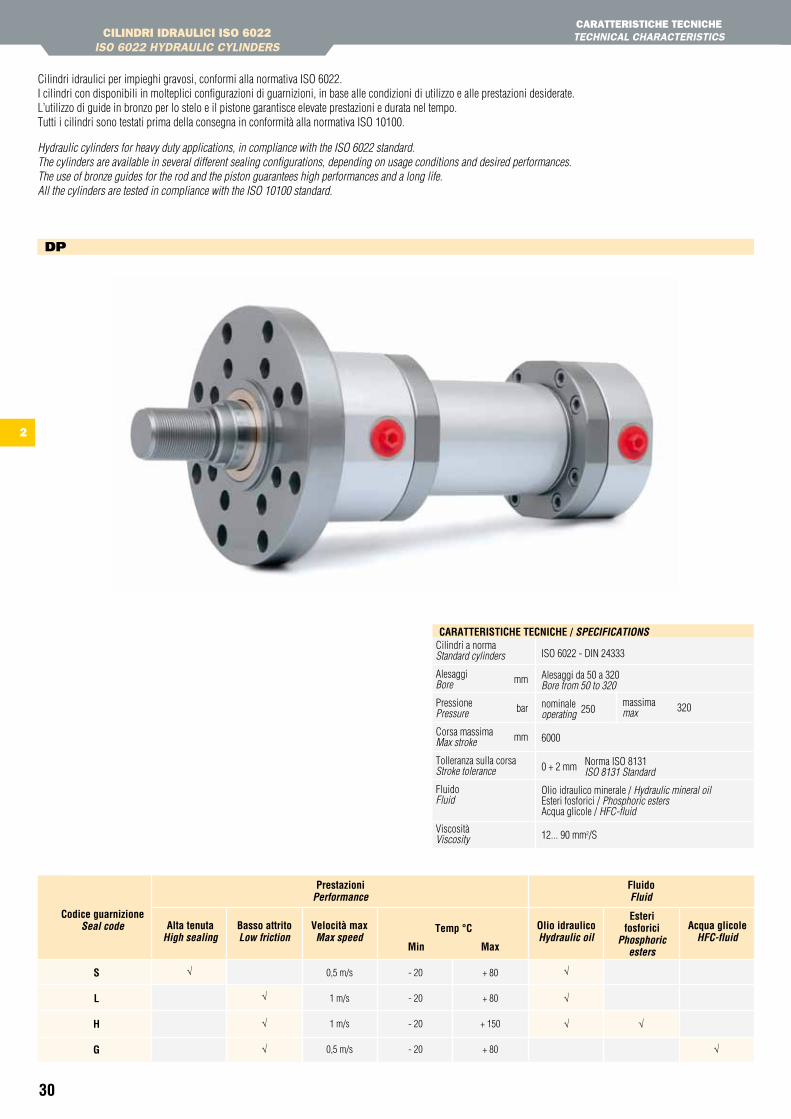
Cilindri idraulici per impieghi gravosi, conformi alla normativa ISO 6022. I cilindri con disponibili in molteplici configurazioni di guarnizioni, in base alle condizioni di utilizzo e alle prestazioni desiderate.L’utilizzo di guide in bronzo per lo stelo e il pistone garantisce elevate prestazioni e durata nel tempo.Tutti i cilindri sono testati prima della consegna in conformità alla normativa ISO 10100.
Hydraulic cylinders for heavy duty applications, in compliance with the ISO 6022 standard. The cylinders are available in several different sealing configurations, depending on usage conditions and desired performances.The use of bronze guides for the rod and the piston guarantees high performances and a long life.All the cylinders are tested in compliance with the ISO 10100 standard.
Cilindri a norma Standard cylinders
Alesaggi mmBore
Pressione bar Pressure
Corsa massima mm Max stroke
Tolleranza sulla corsa Stroke tolerance
Fluido Fluid
Viscosità Viscosity
ISO 6022 - DIN 24333
Alesaggi da 50 a 320 Bore from 50 to 320
nominale 250operating
6000
0 + 2 mm Norma ISO 8131 ISO 8131 Standard
Olio idraulico minerale / Hydraulic mineral oilEsteri fosforici / Phosphoric estersAcqua glicole / HFC-fluid
12... 90 mm2/S
massima 320max
CaratteristiChe teCniChe / SpecificationS
0,5 m/s
1 m/s
1 m/s
0,5 m/s
- 20
- 20
- 20
- 20
+ 80
+ 80
+ 150
+ 80
Codice guarnizioneSeal code alta tenuta
High sealingOlio idraulicoHydraulic oil
esterifosforici
phosphoric esters
acqua glicoleHfc-fluid
Basso attritoLow friction
Velocità maxMax speed
temp °C
Min Max
Prestazioniperformance
Fluidofluid
s L h G
√
√
√
√
√
√
√ √
√
31
2
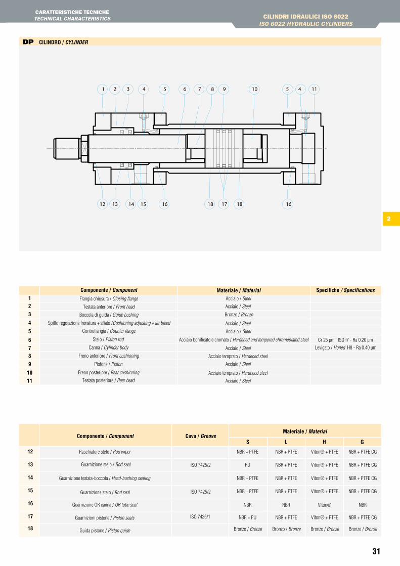
DP CiLinDrO / cYLinDeR
CILINDRI IDRAULICI ISO 6022ISO 6022 HYDRAULIC CYLINDERS
CARAttERIStICHE tECNICHEtECHNICAL CHARACtERIStICS
s L h GCava / GrooveComponente / component
Materiale / Material
12
13
14
15
16
17
18
Raschiatore stelo / Rod wiper
Guarnizione testata-boccola / Head-bushing sealing
Guarnizioni pistone / Piston seals
Guarnizione stelo / Rod seal ISO 7425/2
ISO 7425/2
NBR + PTFE
NBR + PTFE
NBR + PTFE
NBR + PTFE
NBR + PTFE
NBR + PTFE
NBR + PTFE CG
NBR + PTFE CG
NBR + PTFE CG
Viton® + PTFE
Viton® + PTFE
Viton® + PTFE
PU NBR + PTFE NBR + PTFE CGViton® + PTFE
NBR NBR NBRViton®
NBR + PU NBR + PTFE NBR + PTFE CGViton® + PTFEISO 7425/1
Guarnizione OR canna / OR tube seal
Guarnizione stelo / Rod seal
Guida pistone / Piston guide Bronzo / Bronze Bronzo / Bronze Bronzo / BronzeBronzo / Bronze
Materiale / Material spec.Componente / componentFlangia chiusura / Closing flange
Bronzo / BronzeBoccola di guida / Guide bushing
Testata anteriore / Front head
Spillo regolazione frenatura + sfiato /Cushioning adjusting + air bleed
Testata posteriore / Rear head
Acciaio / Steel
Acciaio / Steel
Acciaio / Steel
Acciaio / Steel
Levigato / Honed H8 - Ra 0.40 µm
Cr 25 µm ISO f7 - Ra 0.20 µmStelo / Piston rod
Canna / Cylinder body
Pistone / Piston
Freno anteriore / Front cushioning
Freno posteriore / Rear cushioning
Acciaio bonificato e cromato / Hardened and tempered chromeplated steel
Acciaio / Steel
Acciaio / Steel
Acciaio temprato / Hardened steel
Acciaio temprato / Hardened steel
Acciaio / Steel
12
3
4
5
6
78
9
10
11
Materiale / Material specifiche / SpecificationsComponente / component
Controflangia / Counter flange
441 9 11107652 53 8
12 13 14 16 17 1615 1818
32
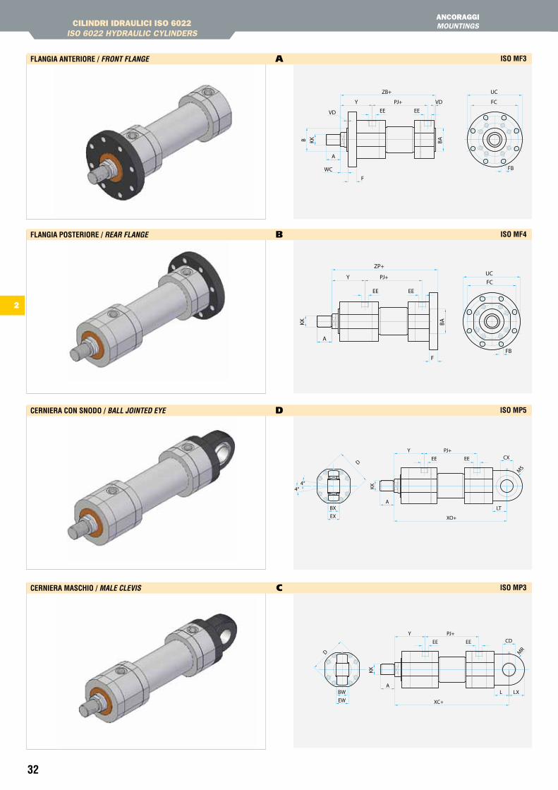
CILINDRI IDRAULICI ISO 6022ISO 6022 HYDRAULIC CYLINDERS
ANCORAggIMOUNtINGS
FLanGia anteriOre / fRont fLanGe A isO MF3
FLanGia POsteriOre / ReaR fLanGe b isO MF4
Cerniera COn snODO / BaLL JointeD eYe D isO MP5
Cerniera MasChiO / MaLe cLeViS C isO MP3
BA
ZP+
PJ+YFC
FB
UC
F
KK
A
EEEE
VD
UC
F
FB
FC
VD
B
WC
Y PJ+
ZB+
BAKK
A
EEEE
4°4°
CX
BXEX
LT
Y PJ+
XO+
KK
A
EEEED
MS
XC+
L LX
CDPJ+Y
KK
A
EEEE
MRD
BWEW
2
2
33
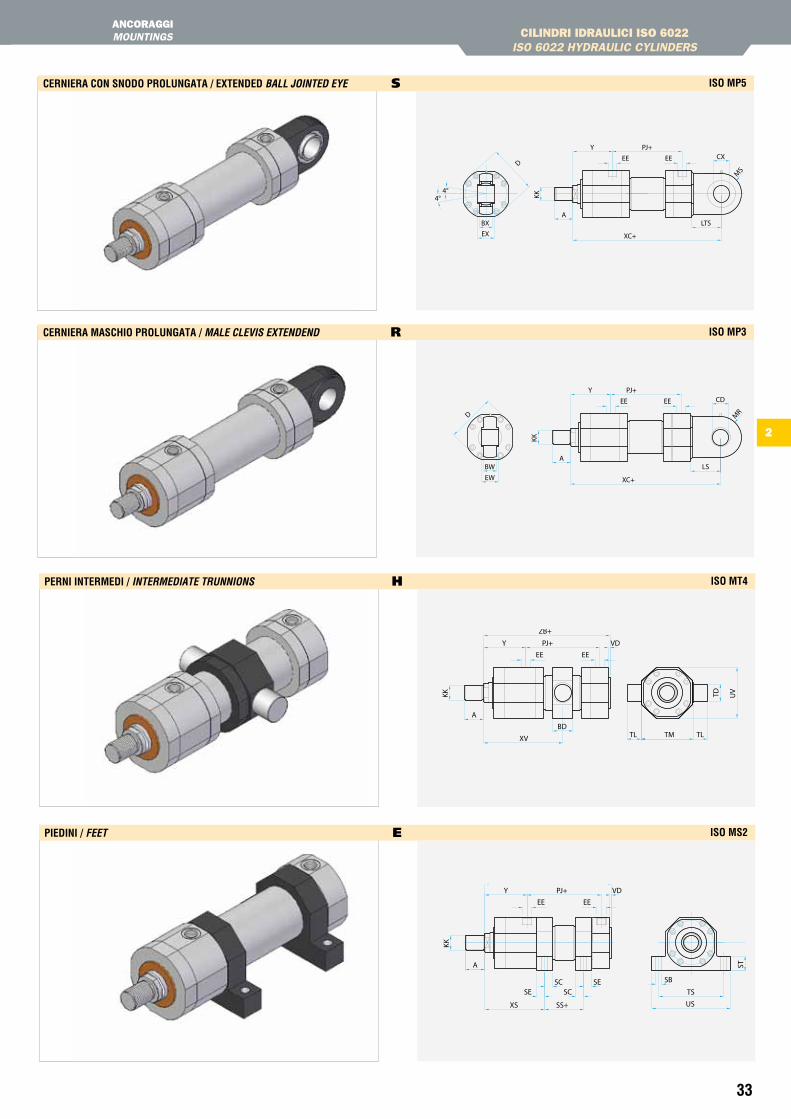
CILINDRI IDRAULICI ISO 6022ISO 6022 HYDRAULIC CYLINDERS
ANCORAggIMOUNtINGS
Cerniera COn snODO PrOLunGata / eXtenDeD BaLL JointeD eYe s isO MP5
Cerniera MasChiO PrOLunGata / MaLe cLeViS eXtenDenD R isO MP3
Perni interMeDi / inteRMeDiate tRunnionS h isO Mt4
PieDini / feet e isO Ms2
4°4°
BXEX
D EE EE
A
KK
Y PJ+CX
LTS
XC+
MS
XC+
LS
CD
EWBW
PJ+Y
KK
A
EEEED
MR
TD UV
TLTL TMBD
XV
Y PJ+
ZB+
VD
KK
A
EEEE
LH
SB
US
TSSC
SESE
SC
SS+XS
VDZB+
PJ+Y
ST
KK
A
EEEE
34
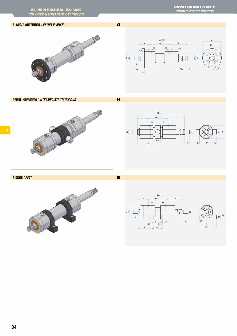
Perni interMeDi / inteRMeDiate tRunnionS h
FLanGia anteriOre / fRont fLanGe A
PieDini / feet e
CILINDRI IDRAULICI ISO 6022ISO 6022 HYDRAULIC CYLINDERS
ANCORAggI DOPPIO StELO DOUBLE ROD MOUNtINGS
UC
F
FB
FC
VD
BA
WC
Y PJ1+
BA
VD
WC+
Y+
ZB3++
KK
A
A
KK
EEEE
Y+
ZB3++
Y PJ1+
TD UV
TLTL TMBD
XV
KK
A
A
KK
EEEE
BA
ZB3++
Y+
SCSE
SESC
SS+XS
SB
US
TS
PJ1+Y
LH
KK
A
A
KK
ST
EEEE
2
35
2
CILINDRI IDRAULICI ISO 6022ISO 6022 HYDRAULIC CYLINDERS
DIMENSIONIDIMENSIONS
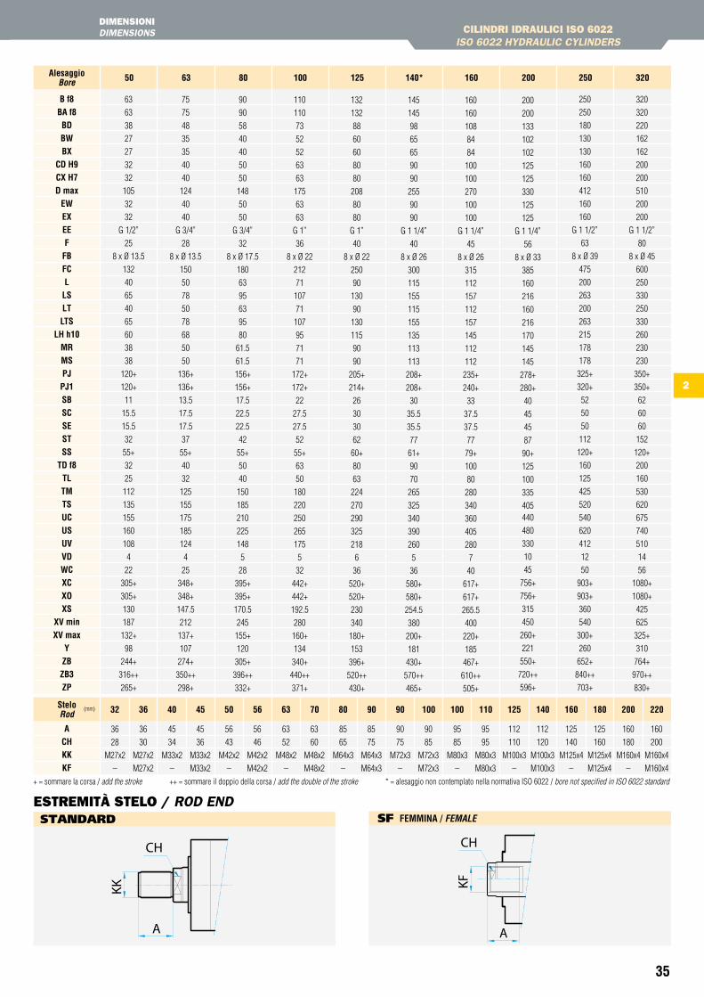
+ = sommare la corsa / add the stroke ++ = sommare il doppio della corsa / add the double of the stroke * = alesaggio non contemplato nella normativa ISO 6022 / bore not specified in ISO 6022 standard
B f8Ba f8BDBWBX
CD h9CX h7D max
eWeXeeF
FBFCL
LsLtLts
Lh h10MrMsPJPJ1sBsCsestss
tD f8tLtMtsuCusuVVDWCXCXOXs
XV minXV max
YZBZB3ZP
63
63
38
27
27
32
32
105
32
32
G 1/2”
25
8 x Ø 13.5
132
40
65
40
65
60
38
38
120+
120+
11
15.5
15.5
32
55+
32
25
112
135
155
160
108
4
22
305+
305+
130
187
132+
98
244+
316++
265+
75
75
48
35
35
40
40
124
40
40
G 3/4”
28
8 x Ø 13.5
150
50
78
50
78
68
50
50
136+
136+
13.5
17.5
17.5
37
55+
40
32
125
155
175
185
124
4
25
348+
348+
147.5
212
137+
107
274+
350++
298+
90
90
58
40
40
50
50
148
50
50
G 3/4”
32
8 x Ø 17.5
180
63
95
63
95
80
61.5
61.5
156+
156+
17.5
22.5
22.5
42
55+
50
40
150
185
210
225
148
5
28
395+
395+
170.5
245
155+
120
305+
396++
332+
110
110
73
52
52
63
63
175
63
63
G 1”
36
8 x Ø 22
212
71
107
71
107
95
71
71
172+
172+
22
27.5
27.5
52
55+
63
50
180
220
250
265
175
5
32
442+
442+
192.5
280
160+
134
340+
440++
371+
132
132
88
60
60
80
80
208
80
80
G 1”
40
8 x Ø 22
250
90
130
90
130
115
90
90
205+
214+
26
30
30
62
60+
80
63
224
270
290
325
218
6
36
520+
520+
230
340
180+
153
396+
520++
430+
145
145
98
65
65
90
90
255
90
90
G 1 1/4”
40
8 x Ø 26
300
115
155
115
155
135
113
113
208+
208+
30
35.5
35.5
77
61+
90
70
265
325
340
390
260
5
36
580+
580+
254.5
380
200+
181
430+
570++
465+
160
160
108
84
84
100
100
270
100
100
G 1 1/4”
45
8 x Ø 26
315
112
157
112
157
145
112
112
235+
240+
33
37.5
37.5
77
79+
100
80
280
340
360
405
280
7
40
617+
617+
265.5
400
220+
185
467+
610++
505+
200
200
133
102
102
125
125
330
125
125
G 1 1/4”
56
8 x Ø 33
385
160
216
160
216
170
145
145
278+
280+
40
45
45
87
90+
125
100
335
405440
480
330
10
45
756+
756+
315
450
260+
221
550+
720++
596+
250
250
180
130
130
160
160
412
160
160
G 1 1/2”
63
8 x Ø 39
475
200
263
200
263
215
178
178
325+
320+
52
50
50
112
120+
160
125
425
520
540
620
412
12
50
903+
903+
360
540
300+
260
652+
840++
703+
320
320
220
162
162
200
200
510
200
200
G 1 1/2”
80
8 x Ø 45
600
250
330
250
330
260
230
230
350+
350+
62
60
60
152
120+
200
160
530
620
675
740
510
14
56
1080+
1080+
425
625
325+
310
764+
970++
830+
50 63 80 100 125 140* 160 200 250 320alesaggioBore
aChKKKF
36 36
28 30
M27x2 M27x2
– M27x2
45 45
34 36
M33x2 M33x2
– M33x2
56 56
43 46
M42x2 M42x2
– M42x2
63 63
52 60
M48x2 M48x2
– M48x2
85 85
65 75
M64x3 M64x3
– M64x3
90 90
75 85
M72x3 M72x3
– M72x3
95 95
85 95
M80x3 M80x3
– M80x3
112 112
110 120
M100x3 M100x3
– M100x3
125 125
140 160
M125x4 M125x4
– M125x4
160 160
180 200
M160x4 M160x4
– M160x4
32 36 40 45 50 56 63 70 80 90 90 100 100 110 125 140 160 180 200 220steloRod
(mm)
KK
A
CH
KF
A
CH
EStREMItà StELO / ROD END sF FeMMina / feMaLe sTAnDARD
36
8080706065555000
506380100125160200250320
BL
BK
BW1
4
3
1
2
3
4
alesaggioBore(mm)
DB max (mm)
sensOri Di PrOssiMità / pRoXiMitY SwitcHeS
DB
DB
2 Il drenaggio della boccola impedisce l’accumulo di fluido dietro al raschiatore. Una connessione situata tra il raschiatore e la tenuta a labbro consente il rinvio al serbatoio del fluido. Il drenaggio è normalmente posizionato sullo stesso lato della bocca olio.
The bushing drain avoids the accumulation of liquid behind the scraper. A connection between the scraper and the lip seal allows to send the fluid back to the tank. The drain is usually installed on the same side of the oil head.
3
1ee2
ee1
3
1
2
2
4
4
CILINDRI IDRAULICI ISO 6022ISO 6022 HYDRAULIC CYLINDERS
OPzIONI ED ESECUzIONI SPECIALIOPtIONS AND SPECIAL EXECUtIONS
506380100125140160200250320
alesaggioBore anteriore
frontG 1/2”G 3/4”G 3/4”G 1”G 1”
G 1 1/4”G 1 1/4”G 1 1/4”G 1 1/2”G 1 1/2”
G 1/2”G 3/4”G 3/4”G 1”G 1”
G 1 1/4”G 1 1/4”G 1 1/4”G 1 1/2”G 1 1/2”
standardPosteriore
Rear
isO 1179-1 (Gas) sae 3000-6000
anteriorefrontG 3/4”G 1”G 1”
G 1 1/4”G 1 1/4”G 1 1/2”G 1 1/2”G 1 1/2”
G 2”–
G 3/4”G 1”G 1”
G 1 1/4”G 1 1/4”G 1 1/2”G 1 1/2”G 1 1/2”
G 2”–
Maggiorate / oversizePosteriore
Rearanteriore
front–
1/2”1/2”3/4”3/4”1”1”1”
1 1/4”1 1/4”
–1/2”1/2”3/4”3/4”1”1”1”
1 1/4”1 1/4”
standardPosteriore
Rearanteriore
front–––1”1”
1 1/4”1 1/4”1 1/4”1 1/2”1 1/2”
–––1”1”
1 1/4”1 1/4”1 1/4”1 1/2”1 1/2”
Maggiorate / oversizePosteriore
Rear
Per caratteristiche e modalità di funzionamento del sensore fare riferimento alla documentazione a 14.For proximity switches features, see documentation at 14.
OrientaMentO COnnessiOni / poRt Location
sD DrenaGGiO BOCCOLa / BuSHinG DRain
Sensore anteriore / Front sensor
Sensore posteriore / Rear sensor
Sensore anteriore e posteriore / Front and rear sensor
sPv sPZ sPK
Stelo INOX cromato / Stainless steel chromeplated rod
Stelo temprato cromato / Hardened chromeplated rod
Stelo Nikrom / Nikrom rod
RRx RRh RRK
OPZiOni steLO / RoD enD
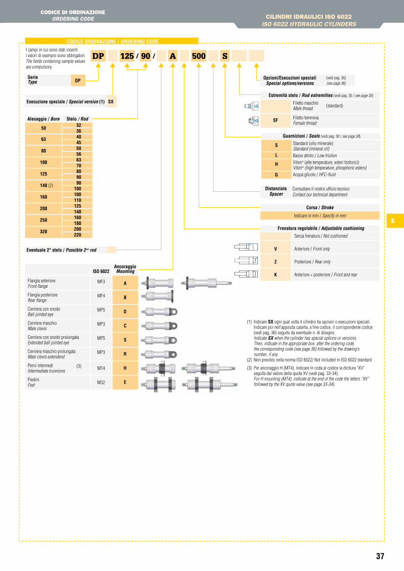
37
2
CODiCe OrDinaZiOne / oRDeRinG coDe
90DP 125 A 500/ /I campi in cui sono stati inseriti i valori di esempio sono obbligatori.The fields containing sample values are compulsory.
serie type DP
esecuzione speciale / Special version (1) sX
stelo / Rod
50
63
80
100
125
140 (2)
160
200
250
320
3236404550566370809090
100100110125140160180200220
alesaggio / Bore
eventuale 2° stelo / possible 2nd rod
ancoraggioMounting
MF3
MF4
MP5
MP3
MP5
MP3
MT4
MS2
Flangia anteriore Front flange
Flangia posteriore Rear flange
Cerniera con snodo Ball jointed eye
Cerniera maschio Male clevis
Cerniera con snodo prolungata Extended ball jointed eye
Cerniera maschio prolungata Male clevis extendend
Perni intermedi Intermediate trunnions
Piedini Feet
a
B
D
C
s
r
h
e
isO 6022
(3)
estremità stelo / Rod extremities (vedi pag. 35 / see page 35)
sF
Filetto maschio Male thread
Filetto femmina Female thread
(standard)
Corsa / Stroke
Indicare in mm / Specify in mm
Frenatura regolabile / adjustable cushioning
V
Z
K
Senza frenatura / Not cushioned
Anteriore / Front only
Posteriore / Rear only
Anteriore + posteriore / Front and rear
DistanzialeSpacer
Consultare il nostro ufficio tecnicoContact our technical department
(1) Indicare sX ogni qual volta il cilindro ha opzioni o esecuzioni speciali.Indicare poi nell’apposita casella, a fine codice, il corrispondente codice (vedi pag. 36) seguito da eventuale n. di disegno.
Indicate SX when the cylinder has special options or versions. Then, indicate in the appropriate box, after the ordering code, the corresponding code (see page 36) followed by the drawing’s number, if any.(2) Non previsto nella norma ISO 6022/ Not included in ISO 6022 standard
(3) Per ancoraggio H (MT4), indicare in coda al codice la dicitura “XV” seguita dal valore della quota XV (vedi pag. 33-34). For H mounting (MT4), indicate at the end of the code the letters “XV” followed by the XV quote value (see page 33-34).
Opzioni/esecuzioni speciali Special options/versions
(vedi pag. 36) (see page 36)
CILINDRI IDRAULICI ISO 6022ISO 6022 HYDRAULIC CYLINDERS
CODICE DI ORDINAzIONEORDERING CODE
Guarnizioni / Seals (vedi pag. 30 / see page 30)
Standard (olio minerale) Standard (mineral oil)Basso attrito / Low frictionViton® (alte temperature, esteri fosforici)Viton® (high temperature, phosphoric esters)Acqua glicole / HFC-fluid
s
L
h
G
S
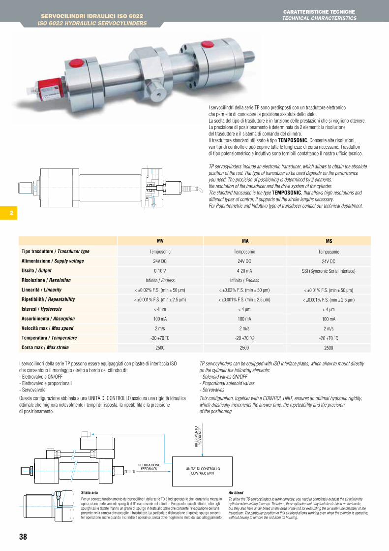
38
Temposonic
24V DC
0-10 V
Infinita / Endless
< ±0.02% F.S. (min ± 50 µm)
< ±0.001% F.S. (min ± 2.5 µm)
< 4 µm
100 mA
2 m/s
-20 +70 ˚C
2500
MV
Temposonic
24V DC
4-20 mA
Infinita / Endless
< ±0.02% F.S. (min ± 50 µm)
< ±0.001% F.S. (min ± 2.5 µm)
< 4 µm
100 mA
2 m/s
-20 +70 ˚C
2500
Ma
Temposonic
24V DC
SSI (Syncronic Serial Interface)
< ±0.01% F.S. (min ± 50 µm)
< ±0.001% F.S. (min ± 2.5 µm)
< 4 µm
100 mA
2 m/s
-20 +70 ˚C
2500
Ms
tipo trasduttore / transducer type
alimentazione / Supply voltage
uscita / output
risoluzione / Resolution
Linearità / Linearity
ripetibilità / Repeatability
isteresi / Hysteresis
assorbimento / absorption
Velocità max / Max speed
temperatura / temperature
Corsa max / Max stroke
I servocilindri della serie TP possono essere equipaggiati con piastre di interfaccia ISO che consentono il montaggio diretto a bordo del cilindro di: - Elettrovalvole ON/OFF - Elettrovalvole proporzionali - Servovalvole
Questa configurazione abbinata a una UNITà DI CONTROLLO assicura una rigidità idraulica ottimale che migliora notevolmente i tempi di risposta, la ripetibilità e la precisione di posizionamento.
TP servocylinders can be equipped with ISO interface plates, which allow to mount directly on the cylinder the following elements: - Solenoid valves ON/OFF - Proportional solenoid valves - Servovalves
This configuration, together with a CONTROL UNIT, ensures an optimal hydraulic rigidity, which drastically increments the answer time, the repeteability and the precision of the positioning.
sfiato aria
Per un corretto funzionamento dei servocilindri della serie TD è indispensabile che, durante la messa in opera, siano perfettamente spurgati dall’aria presente nel cilindro. Per questo, questi cilindri, oltre agli spurghi sulle testate, hanno un grano di spurgo in testa allo stelo che consente l’evaquazione dell’aria presente nella camera che accoglie il trasduttore. La particolare dislocazione di questo spurgo consen-te l’operazione anche quando il cilindro è operativo, senza dover togliere lo stelo dal suo alloggiamento.
air bleed
To allow the TD servocylinders to work correctly, you need to completely exhaust the air within the cylinder when setting them up. Therefore, these cylinders not only include air bleed on the heads, but they also have an air bleed on the head of the rod for exhausting the air within the chamber of the transducer. The particular position of this air bleed allows working even when the cylinder is operative, without having to remove the rod from its housing.
I servocilindri della serie TP sono predisposti con un trasduttore elettronico che permette di conoscere la posizione assoluta dello stelo. La scelta del tipo di trasduttore è in funzione delle prestazioni che si vogliono ottenere. La precisione di posizionamento è determinata da 2 elementi: la risoluzione del trasduttore e il sistema di comando del cilindro. Il trasduttore standard utilizzato è tipo teMPOsOniC. Consente alte risoluzioni, vari tipi di controllo e può coprire tutte le lunghezze di corsa necessarie. Trasduttori di tipo potenziometrico e induttivo sono fornibili contattando il nostro ufficio tecnico.
TP servocylinders include an electronic transducer, which allows to obtain the absolute position of the rod. The type of transducer to be used depends on the performance you need. The precision of positioning is determined by 2 elements: the resolution of the transducer and the drive system of the cylinder. The standard transudec is the type teMPOsOniC, that allows high resolutions and different types of control; it supports all the stroke lengths necessary.For Potentiometric and Induttivo type of transducer contact our technical department.
SERVOCILINDRI IDRAULICI ISO 6022ISO 6022 HYDRAULIC SERVOCYLINDERS
CARAttERIStICHE tECNICHE tECHNICAL CHARACtERIStICS
2
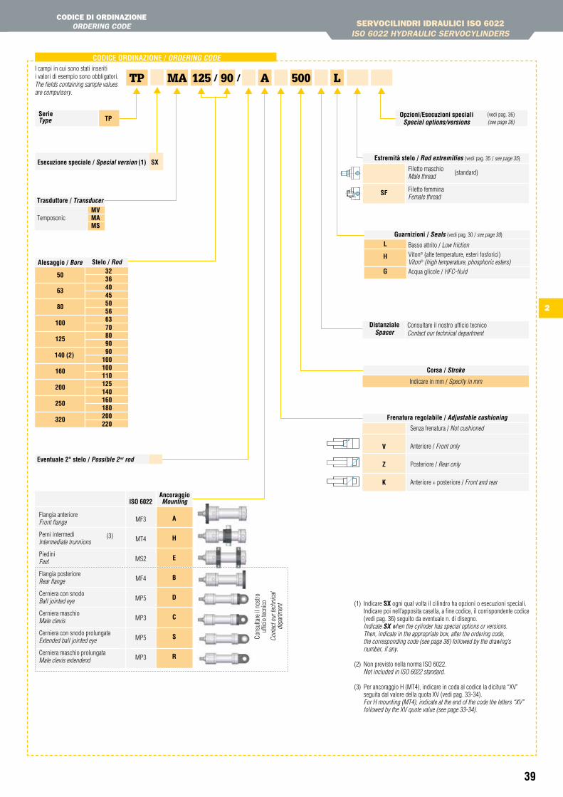
39
ancoraggioMounting
CODiCe OrDinaZiOne / oRDeRinG coDe
90TP MA 125 A 500/ /I campi in cui sono stati inseriti i valori di esempio sono obbligatori.The fields containing sample values are compulsory.
serie type tP
trasduttore / transducer MVTemposonic Ma Ms
stelo / Rod
50
63
80
100
125
140 (2)
160
200
250
320
3236404550566370809090
100100110125140160180200220
alesaggio / Bore
eventuale 2° stelo / possible 2nd rod
MF3
MT4
MS2
MF4
MP5
MP3
MP5
MP3
Flangia anteriore Front flange
Perni intermedi Intermediate trunnions
Piedini Feet
Flangia posteriore Rear flange
Cerniera con snodo Ball jointed eye
Cerniera maschio Male clevis
Cerniera con snodo prolungata Extended ball jointed eye
Cerniera maschio prolungata Male clevis extendend
a
h
e
B
D
C
s
r
isO 6022
(3)
estremità stelo / Rod extremities (vedi pag. 35 / see page 35)
sF
Filetto maschio Male thread
Filetto femmina Female thread
(standard)
DistanzialeSpacer
Consultare il nostro ufficio tecnicoContact our technical department
Corsa / Stroke
Indicare in mm / Specify in mm
Frenatura regolabile / adjustable cushioning
V
Z
K
Senza frenatura / Not cushioned
Anteriore / Front only
Posteriore / Rear only
Anteriore + posteriore / Front and rear
Cons
ulta
re il
nos
tro
uffic
io te
cnic
oCo
ntac
t our
tech
nica
l de
partm
ent
esecuzione speciale / Special version (1) sX
(1) Indicare sX ogni qual volta il cilindro ha opzioni o esecuzioni speciali.Indicare poi nell’apposita casella, a fine codice, il corrispondente codice (vedi pag. 36) seguito da eventuale n. di disegno.
Indicate SX when the cylinder has special options or versions. Then, indicate in the appropriate box, after the ordering code, the corresponding code (see page 36) followed by the drawing’s number, if any.
(2) Non previsto nella norma ISO 6022. Not included in ISO 6022 standard.
(3) Per ancoraggio H (MT4), indicare in coda al codice la dicitura “XV” seguita dal valore della quota XV (vedi pag. 33-34). For H mounting (MT4), indicate at the end of the code the letters “XV” followed by the XV quote value (see page 33-34).
Opzioni/esecuzioni speciali Special options/versions
(vedi pag. 36) (see page 36)
SERVOCILINDRI IDRAULICI ISO 6022ISO 6022 HYDRAULIC SERVOCYLINDERS
CODICE DI ORDINAzIONEORDERING CODE
Guarnizioni / Seals (vedi pag. 30 / see page 30)
Basso attrito / Low frictionViton® (alte temperature, esteri fosforici)Viton® (high temperature, phosphoric esters)Acqua glicole / HFC-fluid
L
h
G
L
2
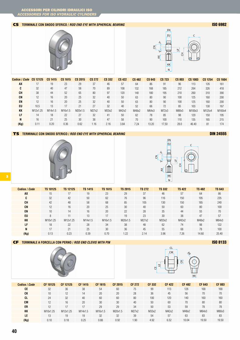
40
CF 643168
70
160
80
78
M64x3
83
19.50
CF 482126
56
140
70
59
M48x2
63
10.04
CF 422113
45
120
60
53
M42x2
57
6.52
CF 33299
36
100
50
50
M33x2
54
4.92
CF 27275
28
80
40
34
M27x2
39
1.90
CF 201560
20
60
30
29
M20x1.5
32
0.92
CF 161554
20
60
30
29
M16x1.5
32
0.88
CF 141538
14
40
20
17
M14x1.5
19
0.25
CF 1212536
12
32
16
17
M12x1.25
19
0.18
CF 1012532
10
24
12
12
M10x1.25
13
0.10
Codice / codeCeCKCLCMerKKLe
(Kg)
CF 803168
70
160
80
78
M80x3
83
19.50
ts 1012515
32
42
12
10
8
M10x1.25
18
17
0.13
Codice / codeaXC
ChCneneuKKLFn
(Kg)
ts 1212517
42
48
16
14
11
M12x1.25
22
21
0.23
ts 141519
50
58
20
16
13
M14x1.5
28
25
0.39
ts 161523
62
68
25
20
17
M16x1.5
34
30
0.70
ts 201529
76
85
30
22
19
M20x1.5
38
36
1.22
ts 27237
96
105
40
28
23
M27x2
48
45
2.14
ts 33246
116
130
50
35
30
M33x2
62
55
3.96
ts 42257
150
150
60
44
38
M42x2
74
68
7.26
ts 48264
195
185
80
55
47
M48x2
98
78
14.60
ts 64386
235
240
100
70
57
M64x3
122
100
25.40
Cs 1212517
32
38
12
12
10.5
M12x1.25
14
16
0.11
Codice / codeaXC
ChCneneuKKLFn
(Kg)
Cs 141519
40
44
16
16
13
M14x1.5
18
21
0.20
Cs 161523
47
52
20
20
17
M16x1.5
22
25
0.36
Cs 201529
58
65
25
25
21
M20x1.5
27
30
0.62
Cs 27237
70
80
32
32
27
M27x2
32
38
1.16
Cs 33246
89
97
40
40
32
M33x2
41
47
2.16
Cs 42257
108
120
50
50
40
M42x2
50
58
3.84
Cs 48264
132
140
63
63
52
M48x2
62
70
7.24
Cs 64386
168
180
80
80
66
M64x3
78
90
13.20
Cs 72391
185
195
90
90
72
M72x3
85
100
17,50
Cs 80396
212
210
100
100
85
M80x3
98
110
28.0
Cs 1003113
264
260
125
125
103
M100x3
120
135
46.40
Cs 1254126
326
310
160
160
130
M125x4
150
165
81
Cs 1604161
418
390
200
200
167
M160x4
195
215
174
ACCESSORI PER CILINDRI IDRAULICI ISOACCESSORIES FOR ISO HYDRAULIC CYLINDERS
Cs terMinaLe COn snODO sFeriCO / RoD enD eYe witH SpHeRicaL BeaRinG ISO 6982
Ts terMinaLe COn snODO sFeriCO / RoD enD eYe witH SpHeRicaL BeaRinG dIn 24555
CF terMinaLe a FOrCeLLa COn PernO / RoD enD cLeViS witH pin ISO 8133
3
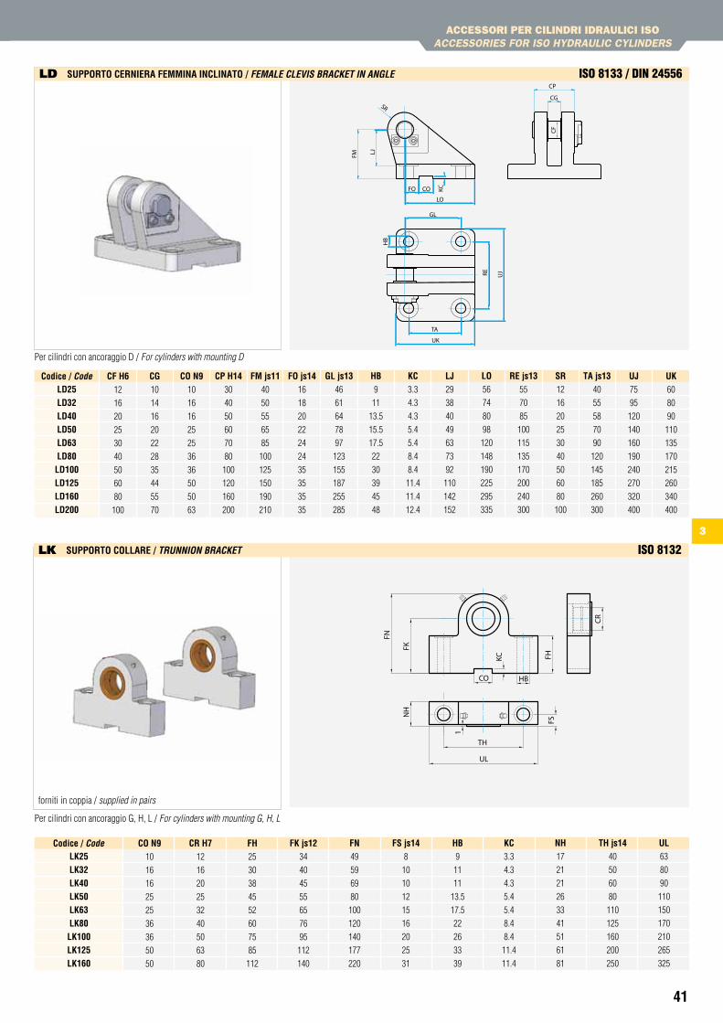
41
LJ29
38
40
49
63
73
92
110
142
152
KC3.3
4.3
4.3
5.4
5.4
8.4
8.4
11.4
11.4
12.4
hB9
11
13.5
15.5
17.5
22
30
39
45
48
GL js1346
61
64
78
97
123
155
187
255
285
FO js1416
18
20
22
24
24
35
35
35
35
FM js1140
50
55
65
85
100
125
150
190
210
CP h1430
40
50
60
70
80
100
120
160
200
CO n910
16
16
25
25
36
36
50
50
63
CG10
14
16
20
22
28
35
44
55
70
CF h612
16
20
25
30
40
50
60
80
100
Codice / codeLD25LD32LD40LD50LD63LD80LD100LD125LD160LD200
LO56
74
80
98
120
148
190
225
295
335
re js1355
70
85
100
115
135
170
200
240
300
sr12
16
20
25
30
40
50
60
80
100
ta js1340
55
58
70
90
120
145
185
260
300
uJ75
95
120
140
160
190
240
270
320
400
uK60
80
90
110
135
170
215
260
340
400
th js1440
50
60
80
110
125
160
200
250
nh17
21
21
26
33
41
51
61
81
KC3.3
4.3
4.3
5.4
5.4
8.4
8.4
11.4
11.4
hB9
11
11
13.5
17.5
22
26
33
39
Fs js148
10
10
12
15
16
20
25
31
Fn49
59
69
80
100
120
140
177
220
FK js1234
40
45
55
65
76
95
112
140
Fh25
30
38
45
52
60
75
85
112
Cr h712
16
20
25
32
40
50
63
80
CO n910
16
16
25
25
36
36
50
50
Codice / codeLK25LK32LK40LK50LK63LK80LK100LK125LK160
uL63
80
90
110
150
170
210
265
325
CR
FHKC
HBCO
FN
NH
FK
UL
TH
1
FS
Per cilindri con ancoraggio D / For cylinders with mounting D
Per cilindri con ancoraggio G, H, L / For cylinders with mounting G, H, L
ACCESSORI PER CILINDRI IDRAULICI ISOACCESSORIES FOR ISO HYDRAULIC CYLINDERS
CG
CP
GL
TA
RE UJ
UK
FM
FO CO KC
LO
LJ
CF
SR
HB
lD suPPOrtO Cerniera FeMMina inCLinatO / feMaLe cLeViS BRacket in anGLe ISO 8133 / dIn 24556
lK suPPOrtO COLLare / tRunnion BRacket ISO 8132
forniti in coppia / supplied in pairs
3
43
CILINDRI IDRAULICI COMPAttI LEggERILIGHt COMPACt HYDRAULIC CYLINDERS
CARAttERIStICHE tECNICHE tECHNICAL CHARACtERIStICS
ANCORAggI E DIMENSIONIMOUNtING AND DIMENSION
ANCORAggI E DIMENSIONIMOUNtING AND DIMENSION
OPzIONI E ACCESSORIOPtIONS AND ACCESSORIES
CODICE DI ORDINAzIONEORDERING CODE
SENSORI MAgNEtICIMAGNEtIC SWItCHES
CILINDRI IDRAULICI COMPAttI PER IMPIEgHI gRAVOSIHEAVY DUtY COMPACt HYDRAULIC CYLINDERS
CARAttERIStICHE tECNICHE tECHNICAL CHARACtERIStICS
OPzIONI E ACCESSORIOPtIONS AND ACCESSORIES
CODICE DI ORDINAzIONEORDERING CODE
4
44
45
49
46
47
47
48
50
51
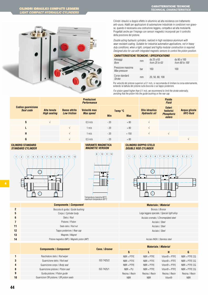
44
4
0,5 m/s
1 m/s
1 m/s
0,5 m/s
- 20
- 20
- 20
- 20
+ 80
+ 80
+ 150
+ 80
Codice guarnizioneSeal code alta tenuta
High sealingOlio idraulicoHydraulic oil
esterifosforici
phosphoric esters
acqua glicoleHfc-fluid
Basso attritoLow friction
Velocità maxMax speed
temp °C
Min Max
Prestazioniperformance
Fluidofluid
√
√
√
√
√
√ √
√
s
L
h
G √
CILINDRI IDRAULICI COMPAttI LEggERILIGHt COMPACt HYDRAULIC CYLINDERS
CARAttERIStICHE tECNICHEtECHNICAL CHARACtERIStICS
Cilindri idraulici a doppio effetto in alluminio ad alta resistenza con trattamento anti-usura. Adatti per applicazioni di automazione industriale in condizioni non gravo-se, quando è necessaria una costruzione leggera, compatta e ad alta modularità. Progettati anche per l’impiego con sensori magnetici incorporati per il controllo della posizione del pistone.
Double acting hydraulic cylinders, realized in high resistance aluminum with wear-resistant coating. Suitable for industrial automation applications, not in heavy duty conditions, when a light, compact and highly modular construction is required. Designed also for use with integrated magnetic sensors to control the piston position.
1281 3 4 7 42 5 9 10 116
CiLinDrO stanDarD StanDaRD cYLinDeR
1498 13
Variante MaGnetiCa MaGnetic VeRSion
132 6 105 2474 31 98
CiLinDrO DOPPiO steLO DouBLe RoD cYLinDeR
Alesaggi da 25 a 63 da 80 a 100Bore from 25 to 63 from 80 to 100
Pressione massima 160 100Max pressure
Corse standard 20, 50, 80, 100 Stroke
CaratteristiChe teCniChe / SpecificationS
mm
bar
mm
Per velocità del pistone superiori a 0.1 m/s, si raccomanda di limitare la corsa esternamente, evitando la battuta del pistone sulla boccola o sul tappo posteriore.
For piston speed higher than 0.1 m/s, we recommend to limit the stroke externally, avoiding that the piston hits the guide bushing or the rear cap.
CILINDRI IDRAULICI COMPAttI LEggERILIGHt COMPACt HYDRAULIC CYLINDERS
s L h GCava / GrooveComponente / component
Materiale / Material
Raschiatore stelo / Rod wiper
Guarnizione corpo / Body seal
Guarnizione stelo / Rod seal ISO 7425/2
NBR + PTFE
NBR + PTFE
NBR + PTFE
NBR + PTFE
NBR + PTFE
NBR + PTFE
NBR + PTFE CG
NBR + PTFE CG
NBR + PTFE CG
Viton® + PTFE
Viton® + PTFE
Viton® + PTFE
NBR
NBR + PU
NBR
NBR + PTFE
NBR
NBR + PTFE CG
Viton®
Viton® + PTFEISO 7425/1
Guida pistone / Piston guide
Guarnizione pistone / Piston seal
Guarnizioni OR pistone / OR piston seals
Resina / Resin Resina / Resin Resina / ResinResina / Resin
1
3
4
89
10
Materiale / Material spec.Componente / componentBronzo / BronzeBoccola di guida / Guide bushing
Stelo / Rod
Corpo / Cylinder body
Pistone / Piston
Lega leggera speciale / Special light alloy
Acciaio / Steel
Acciaio cromato / Chromeplated steel
Acciaio / Steel
Acciaio / Steel
Acciaio INOX / Stainless steel
25
6
7
11
12
13
14
Materiale / MaterialComponente / component
Dado stelo / Rod nut
Tappo posteriore / Rear cap
Magnete / Magnet
Pistone magnetico (MP) / Magnetic piston (MP)
Temperatura massima 80°Cmaximum temperature 80°C
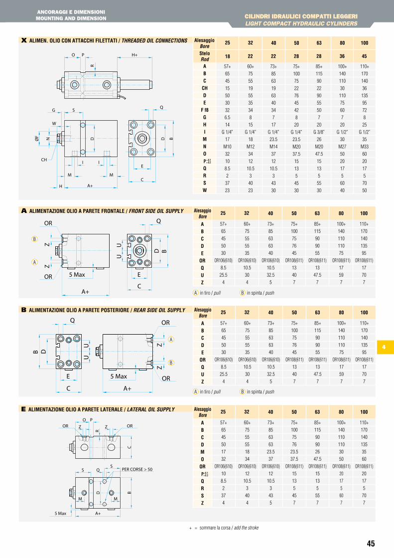
45
4
CILINDRI IDRAULICI COMPAttI LEggERILIGHt COMPACt HYDRAULIC CYLINDERS
ANCORAggI E DIMENSIONIMOUNtINg AND DIMENSION
+ = sommare la corsa / add the stroke
CILINDRI IDRAULICI COMPAttI LEggERILIGHt COMPACt HYDRAULIC CYLINDERS
x aLiMen. OLiO COn attaCChi FiLettati / tHReaDeD oiL connectionS
e aLiMentaZiOne OLiO a Parete LateraLe / LateRaL oiL SuppLY
A+C
E
Q
D B
5 Max
UU
ZZ
OR
OR
A aLiMentaZiOne OLiO a Parete FrOntaLe / fRont SiDe oiL SuppLY
aBCDe
OrQuZ
57+
65
45
50
30
OR106(610)
8.5
25.5
4
alesaggioBore
25
60+
75
55
55
35
OR106(610)
10.5
30
4
73+
85
63
63
40
OR106(610)
10.5
32.5
5
32 40
75+
100
75
76
45
OR108(611)
13
40
7
50
85+
115
90
90
55
OR108(611)
13
47.5
7
63
100+
140
110
110
75
OR108(611)
17
59
7
80
110+
170
140
135
95
OR108(611)
17
70
7
100
A in tiro / pull B in spinta / push
OR
OR
ZZ
UU
5 Max
B D
Q
E
C A+
b aLiMentaZiOne OLiO a Parete POsteriOre / ReaR SiDe oiL SuppLY
aBCDe
OrQuZ
57+
65
45
50
30
OR106(610)
8.5
25.5
4
alesaggioBore
25
60+
75
55
55
35
OR106(610)
10.5
30
4
73+
85
63
63
40
OR106(610)
10.5
32.5
5
32 40
75+
100
75
76
45
OR108(611)
13
40
7
50
85+
115
90
90
55
OR108(611)
13
47.5
7
63
100+
140
110
110
75
OR108(611)
17
59
7
80
110+
170
140
135
95
OR108(611)
17
70
7
100
A in tiro / pull B in spinta / push
aBC
ChDe
F f8GhiMnO
PQrsW
57+
65
45
15
50
30
32
6.5
14
G 1/4”
17
M10
32
10
8.5
2
37
23
steloRod
alesaggioBore
18
25
60+
75
55
19
55
35
34
8
15
G 1/4”
18
M12
34
12
10.5
3
40
23
73+
85
63
19
63
40
34
7
17
G 1/4”
23.5
M14
37
12
10.5
3
43
30
22
32 40
22
75+
100
75
22
76
45
42
8
20
G 1/4”
23.5
M20
37.5
15
13
5
45
30
28
50
85+
115
90
22
90
55
50
7
20
G 3/8”
26
M20
47.5
15
13
5
55
30
28
63
100+
140
110
30
110
75
60
7
20
G 1/2”
30
M27
50
20
17
5
60
40
36
80
110+
170
140
36
135
95
72
8
25
G 1/2”
35
M33
60
20
17
5
70
50
45
100
+ 0.1+ 0.2
aBCDMO
Or
PQrsZ
57+
65
45
50
17
32
OR106(610)
10
8.5
2
37
4
alesaggioBore
25
60+
75
55
55
18
34
OR106(610)
12
10.5
3
40
4
73+
85
63
63
23.5
37
OR106(610)
12
10.5
3
43
5
32 40
75+
100
75
76
23.5
37.5
OR108(611)
15
13
5
45
7
50
85+
115
90
90
26
47.5
OR108(611)
15
13
5
55
7
63
100+
140
110
110
30
50
OR108(611)
20
17
5
60
7
80
110+
170
140
135
35
60
OR108(611)
20
17
5
70
7
100
+ 0.1+ 0.2
A
A
B
B
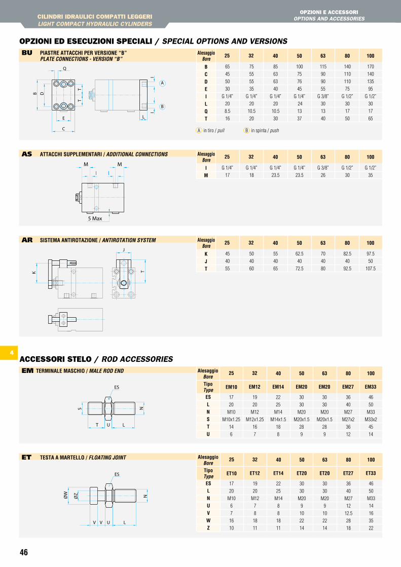
46
CILINDRI IDRAULICI COMPAttI LEggERILIGHt COMPACt HYDRAULIC CYLINDERS
OPzIONI E ACCESSORIOPtIONS AND ACCESSORIES
OPzIONI ED ESECUzIONI SPECIALI / SPECIAL OPtIONS AND VERSIONS
ACCESSORI StELO / ROD ACCESSORIES
bU Piastre attaCChi Per VersiOne “B” pLate connectionS - VeRSion “B”
5 Max
I
MM
I
As attaCChi suPPLeMentari / aDDitionaL connectionS
iM
G 1/4”
17
alesaggioBore
25
G 1/4”
18
G 1/4”
23.5
32 40
G 1/4”
23.5
50
G 3/8”
26
63
G 1/2”
30
80
G 1/2”
35
100
AR sisteMa antirOtaZiOne / antiRotation SYSteM
KJt
45
40
55
alesaggioBore
25
50
40
60
55
40
65
32 40
62.5
40
72.5
50
70
40
80
63
82.5
40
92.5
80
97.5
50
107.5
100
eM terMinaLe MasChiO / MaLe RoD enD
eT testa a MarteLLO / fLoatinG Joint
esLnuVWZ
17
20
M10
6
7
16
10
tipotype
alesaggioBore
et10
25
19
20
M12
7
8
18
11
22
25
M14
8
8
18
11
et12
32 40
et14
30
30
M20
9
10
22
14
et20
50
30
30
M20
9
10
22
14
et20
63
36
40
M27
12
12.5
28
18
et27
80
46
50
M33
14
16
35
22
et33
100
BCDeiLQt
65
45
50
30
G 1/4”
20
8.5
16
alesaggioBore
25
75
55
55
35
G 1/4”
20
10.5
20
85
63
63
40
G 1/4”
20
10.5
30
32 40
100
75
76
45
G 1/4”
24
13
37
50
115
90
90
55
G 3/8”
30
13
40
63
140
110
110
75
G 1/2”
30
17
50
80
170
140
135
95
G 1/2”
30
17
65
100
A in tiro / pull B in spinta / push
esLnstu
17
20
M10
M10x1.25
14
6
tipotype
alesaggioBore
eM10
25
19
20
M12
M12x1.25
16
7
22
25
M14
M14x1.5
18
8
eM12
32 40
eM14
30
30
M20
M20x1.5
28
9
eM20
50
30
30
M20
M20x1.5
28
9
eM20
63
36
40
M27
M27x2
36
12
eM27
80
46
50
M33
M33x2
45
14
eM33
100
4
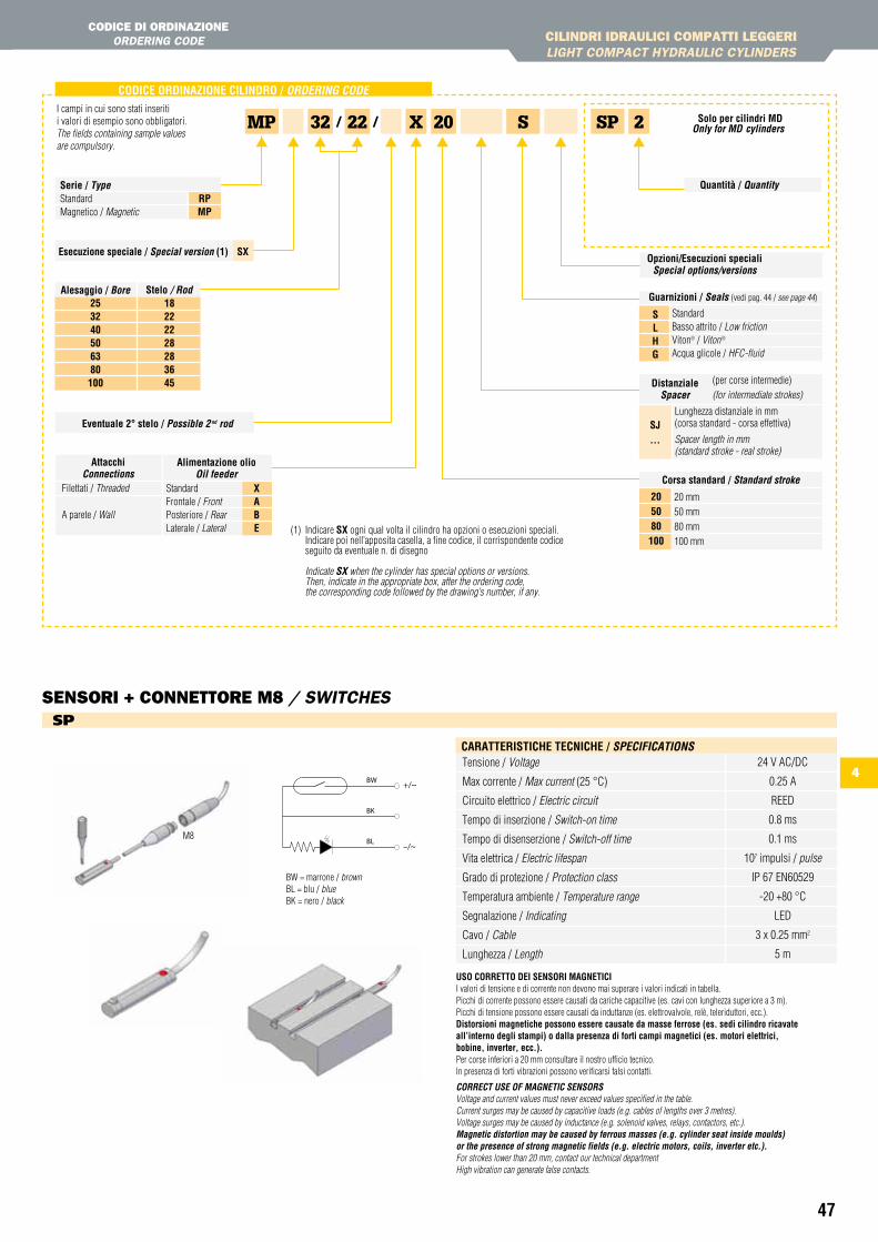
47
4
CILINDRI IDRAULICI COMPAttI LEggERILIGHt COMPACt HYDRAULIC CYLINDERS
CODICE DI ORDINAzIONEORDERING CODE
tECHNICAL CHARACtERIStICS
CODiCe OrDinaZiOne CiLinDrO / oRDeRinG coDe
XMP S20 SP 2
(1) Indicare sX ogni qual volta il cilindro ha opzioni o esecuzioni speciali. Indicare poi nell’apposita casella, a fine codice, il corrispondente codice seguito da eventuale n. di disegno
Indicate SX when the cylinder has special options or versions. Then, indicate in the appropriate box, after the ordering code, the corresponding code followed by the drawing’s number, if any.
I campi in cui sono stati inseriti i valori di esempio sono obbligatori.The fields containing sample values are compulsory.
esecuzione speciale / Special version (1) sX
stelo / Rod2532 40506380100
18 222228283645
alesaggio / Bore
eventuale 2° stelo / possible 2 nd rod
Opzioni/esecuzioni specialiSpecial options/versions
Guarnizioni / Seals (vedi pag. 44 / see page 44)
Standard Basso attrito / Low frictionViton® / Viton® Acqua glicole / HFC-fluid
sLhG
DistanzialeSpacer
Lunghezza distanziale in mm(corsa standard - corsa effettiva)
Spacer length in mm(standard stroke - real stroke)
(per corse intermedie)(for intermediate strokes)
sJ ...
Corsa standard / Standard stroke
20 mm50 mm80 mm100 mm
205080100
2232 / /
serie / typeStandardMagnetico / Magnetic
rPMP
usO COrrettO Dei sensOri MaGnetiCiI valori di tensione e di corrente non devono mai superare i valori indicati in tabella.Picchi di corrente possono essere causati da cariche capacitive (es. cavi con lunghezza superiore a 3 m).Picchi di tensione possono essere causati da induttanze (es. elettrovalvole, relè, teleriduttori, ecc.).Distorsioni magnetiche possono essere causate da masse ferrose (es. sedi cilindro ricavateall’interno degli stampi) o dalla presenza di forti campi magnetici (es. motori elettrici,bobine, inverter, ecc.).Per corse inferiori a 20 mm consultare il nostro ufficio tecnico.In presenza di forti vibrazioni possono verificarsi falsi contatti.
coRRect uSe of MaGnetic SenSoRSVoltage and current values must never exceed values specified in the table.Current surges may be caused by capacitive loads (e.g. cables of lengths over 3 metres).Voltage surges may be caused by inductance (e.g. solenoid valves, relays, contactors, etc.). Magnetic distortion may be caused by ferrous masses (e.g. cylinder seat inside moulds) or the presence of strong magnetic fields (e.g. electric motors, coils, inverter etc.).For strokes lower than 20 mm, contact our technical departmentHigh vibration can generate false contacts.
Tensione / Voltage
Max corrente / Max current (25 °C)
Circuito elettrico / Electric circuit
Tempo di inserzione / Switch-on time
Tempo di disenserzione / Switch-off time
Vita elettrica / Electric lifespan
Grado di protezione / Protection class
Temperatura ambiente / Temperature range
Segnalazione / Indicating
Cavo / Cable
Lunghezza / Length
CaratteristiChe teCniChe / SpecificationS24 V AC/DC
0.25 A
REED
0.8 ms
0.1 ms
107 impulsi / pulse
IP 67 EN60529
-20 +80 °C
LED
3 x 0.25 mm2
5 m
BW = marrone / brownBL = blu / blueBK = nero / black
M8
sPSENSORI + CONNEttORE M8 / SWItCHES
solo per cilindri MDonly for MD cylinders
Quantità / Quantity
XaBe
alimentazione oliooil feeder
Filettati / Threaded
A parete / Wall
attacchiconnections
StandardFrontale / FrontPosteriore / RearLaterale / Lateral
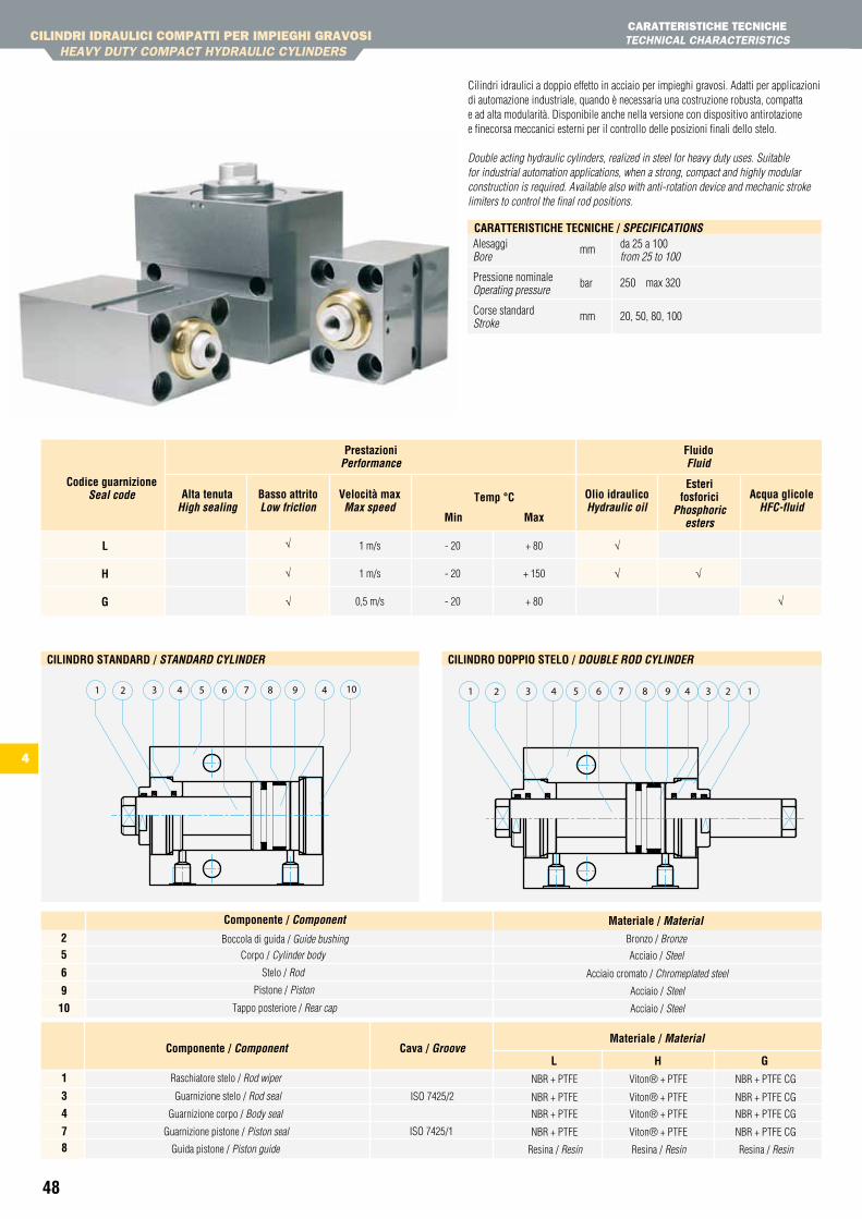
48
1 m/s
1 m/s
0,5 m/s
- 20
- 20
- 20
+ 80
+ 150
+ 80
Codice guarnizioneSeal code alta tenuta
High sealingOlio idraulicoHydraulic oil
esterifosforici
phosphoric esters
acqua glicoleHfc-fluid
Basso attritoLow friction
Velocità maxMax speed
temp °C
Min Max
Prestazioniperformance
Fluidofluid
L h G
√
√
√
√ √
√√
CILINDRI IDRAULICI COMPAttI PER IMPIEgHI gRAVOSI HEAVY DUtY COMPACt HYDRAULIC CYLINDERS
CARAttERIStICHE tECNICHEtECHNICAL CHARACtERIStICS
Cilindri idraulici a doppio effetto in acciaio per impieghi gravosi. Adatti per applicazioni di automazione industriale, quando è necessaria una costruzione robusta, compatta e ad alta modularità. Disponibile anche nella versione con dispositivo antirotazione e finecorsa meccanici esterni per il controllo delle posizioni finali dello stelo. Double acting hydraulic cylinders, realized in steel for heavy duty uses. Suitable for industrial automation applications, when a strong, compact and highly modular construction is required. Available also with anti-rotation device and mechanic stroke limiters to control the final rod positions.
91 3 84 7 42 5 106
CiLinDrO stanDarD / StanDaRD cYLinDeR
652 474 831 9 23 1
CiLinDrO DOPPiO steLO / DouBLe RoD cYLinDeR
Alesaggi da 25 a 100Bore from 25 to 100
Pressione nominale 250 max 320Operating pressure
Corse standard 20, 50, 80, 100 Stroke
CaratteristiChe teCniChe / SpecificationS
mm
bar
mm
4
Cava / GrooveComponente / componentMateriale / Material
Raschiatore stelo / Rod wiper
Guarnizione corpo / Body seal
Guarnizione stelo / Rod seal ISO 7425/2
ISO 7425/1
Guida pistone / Piston guide
Guarnizione pistone / Piston seal
L
NBR + PTFE
NBR + PTFE
NBR + PTFE
NBR + PTFE
Resina / Resin
G
NBR + PTFE CG
NBR + PTFE CG
NBR + PTFE CG
NBR + PTFE CG
Resina / Resin
h
Viton® + PTFE
Viton® + PTFE
Viton® + PTFE
Viton® + PTFE
Resina / Resin
1
3
4
78
Materiale / Material spec.Componente / componentBronzo / BronzeBoccola di guida / Guide bushing
Stelo / Rod
Corpo / Cylinder body
Pistone / Piston
Acciaio / Steel
Acciaio / Steel
Acciaio cromato / Chromeplated steel
Acciaio / Steel
25
6
9
10
Materiale / MaterialComponente / component
Tappo posteriore / Rear cap
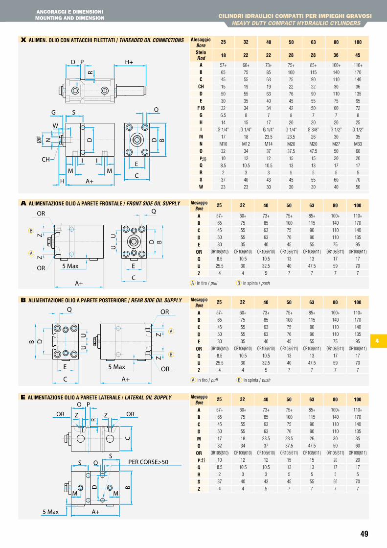
49
4
CILINDRI IDRAULICI COMPAttI PER IMPIEgHI gRAVOSI HEAVY DUtY COMPACt HYDRAULIC CYLINDERS
ANCORAggI E DIMENSIONIMOUNtINg AND DIMENSION
H+
I
O P
R
BD
Q
E
C
S
D
G
NØF
I
W
A+
M
H
M
CH
x aLiMen. OLiO COn attaCChi FiLettati / tHReaDeD oiL connectionS
aBC
ChDe
F f8GhiMnO
PQrsW
57+
65
45
15
50
30
32
6.5
14
G 1/4”
17
M10
32
10
8.5
2
37
23
steloRod
alesaggioBore
18
25
60+
75
55
19
55
35
34
8
15
G 1/4”
18
M12
34
12
10.5
3
40
23
73+
85
63
19
63
40
34
7
17
G 1/4”
23.5
M14
37
12
10.5
3
43
30
22
32 40
22
75+
100
75
22
76
45
42
8
20
G 1/4”
23.5
M20
37.5
15
13
5
45
30
28
50
85+
115
90
22
90
55
50
7
20
G 3/8”
26
M20
47.5
15
13
5
55
30
28
63
100+
140
110
30
110
75
60
7
20
G 1/2”
30
M27
50
20
17
5
60
40
36
80
110+
170
140
36
135
95
72
8
25
G 1/2”
35
M33
60
20
17
5
70
50
45
100
M
A+
D
S
R
PO
5 Max
S
C
M
Z ORZOR
B
PER CORSE>50Q
e aLiMentaZiOne OLiO a Parete LateraLe / LateRaL oiL SuppLY
A+C
E
Q
D B
5 Max
UU
ZZ
OR
OR
A aLiMentaZiOne OLiO a Parete FrOntaLe / fRont SiDe oiL SuppLY
aBCDe
OrQuZ
57+
65
45
50
30
OR106(610)
8.5
25.5
4
alesaggioBore
25
60+
75
55
55
35
OR106(610)
10.5
30
4
73+
85
63
63
40
OR106(610)
10.5
32.5
5
32 40
75+
100
75
76
45
OR108(611)
13
40
7
50
85+
115
90
90
55
OR108(611)
13
47.5
7
63
100+
140
110
110
75
OR108(611)
17
59
7
80
110+
170
140
135
95
OR108(611)
17
70
7
100
A in tiro / pull B in spinta / push
OR
OR
ZZ
UU
5 Max
B D
Q
E
C A+
b aLiMentaZiOne OLiO a Parete POsteriOre / ReaR SiDe oiL SuppLY
A
B
aBCDe
OrQuZ
57+
65
45
50
30
OR106(610)
8.5
25.5
4
alesaggioBore
25
60+
75
55
55
35
OR106(610)
10.5
30
4
73+
85
63
63
40
OR106(610)
10.5
32.5
5
32 40
75+
100
75
76
45
OR108(611)
13
40
7
50
85+
115
90
90
55
OR108(611)
13
47.5
7
63
100+
140
110
110
75
OR108(611)
17
59
7
80
110+
170
140
135
95
OR108(611)
17
70
7
100
A in tiro / pull B in spinta / push
+ 0.1+ 0.2
aBCDMO
Or
PQrsZ
57+
65
45
50
17
32
OR106(610)
10
8.5
2
37
4
alesaggioBore
25
60+
75
55
55
18
34
OR106(610)
12
10.5
3
40
4
73+
85
63
63
23.5
37
OR106(610)
12
10.5
3
43
5
32 40
75+
100
75
76
23.5
37.5
OR108(611)
15
13
5
45
7
50
85+
115
90
90
26
47.5
OR108(611)
15
13
5
55
7
63
100+
140
110
110
30
50
OR108(611)
20
17
5
60
7
80
110+
170
140
135
35
60
OR108(611)
20
17
5
70
7
100
+ 0.1+ 0.2
A
B
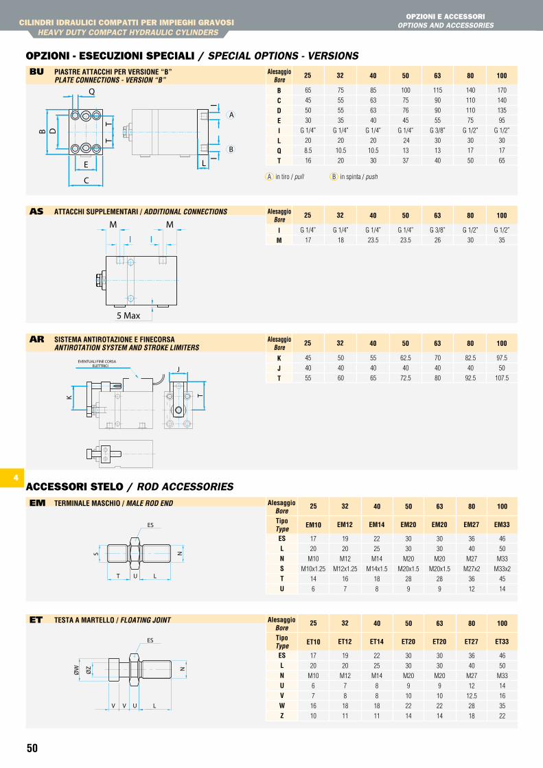
50
CILINDRI IDRAULICI COMPAttI PER IMPIEgHI gRAVOSI HEAVY DUtY COMPACt HYDRAULIC CYLINDERS
OPzIONI E ACCESSORIOPtIONS AND ACCESSORIES
OPzIONI - ESECUzIONI SPECIALI / SPECIAL OPtIONS - VERSIONS
ACCESSORI StELO / ROD ACCESSORIES
TT
B D
Q
E
C
A
B
II
L
bU Piastre attaCChi Per VersiOne “B” pLate connectionS - VeRSion “B”
5 Max
I
MM
I
As attaCChi suPPLeMentari / aDDitionaL connectionS
iM
G 1/4”
17
alesaggioBore
25
G 1/4”
18
G 1/4”
23.5
32 40
G 1/4”
23.5
50
G 3/8”
26
63
G 1/2”
30
80
G 1/2”
35
100
K
J
T
EVENTUALI FINE CORSA ELETTRICI
AR sisteMa antirOtaZiOne e FineCOrsa antiRotation SYSteM anD StRoke LiMiteRS
KJt
45
40
55
alesaggioBore
25
50
40
60
55
40
65
32 40
62.5
40
72.5
50
70
40
80
63
82.5
40
92.5
80
97.5
50
107.5
100
eM terMinaLe MasChiO / MaLe RoD enD
esLnstu
17
20
M10
M10x1.25
14
6
tipotype
alesaggioBore
eM10
25
19
20
M12
M12x1.25
16
7
22
25
M14
M14x1.5
18
8
eM12
32 40
eM14
30
30
M20
M20x1.5
28
9
eM20
50
30
30
M20
M20x1.5
28
9
eM20
63
36
40
M27
M27x2
36
12
eM27
80
46
50
M33
M33x2
45
14
eM33
100
eT testa a MarteLLO / fLoatinG Joint
esLnuVWZ
17
20
M10
6
7
16
10
tipotype
alesaggioBore
et10
25
19
20
M12
7
8
18
11
22
25
M14
8
8
18
11
et12
32 40
et14
30
30
M20
9
10
22
14
et20
50
30
30
M20
9
10
22
14
et20
63
36
40
M27
12
12.5
28
18
et27
80
46
50
M33
14
16
35
22
et33
100
BCDeiLQt
65
45
50
30
G 1/4”
20
8.5
16
alesaggioBore
25
75
55
55
35
G 1/4”
20
10.5
20
85
63
63
40
G 1/4”
20
10.5
30
32 40
100
75
76
45
G 1/4”
24
13
37
50
115
90
90
55
G 3/8”
30
13
40
63
140
110
110
75
G 1/2”
30
17
50
80
170
140
135
95
G 1/2”
30
17
65
100
A in tiro / pull B in spinta / push
4
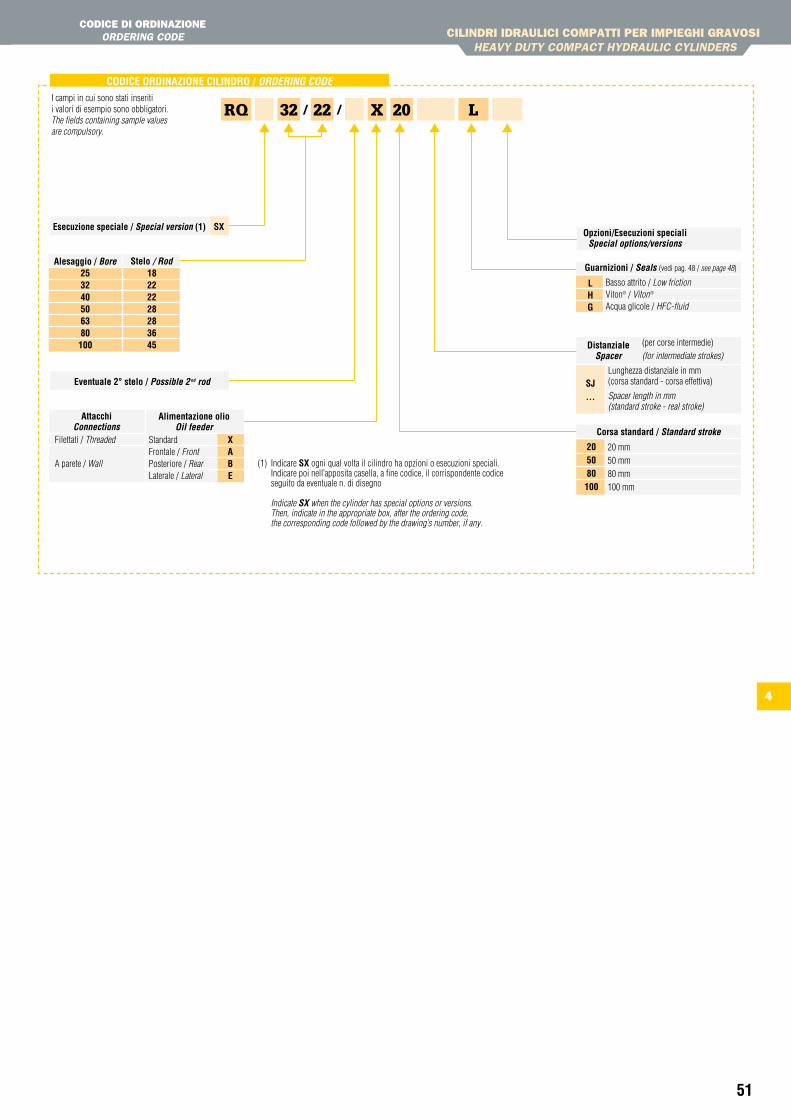
51
CILINDRI IDRAULICI COMPAttI PER IMPIEgHI gRAVOSI HEAVY DUtY COMPACt HYDRAULIC CYLINDERS
CODICE DI ORDINAzIONEORDERING CODE
tECHNICAL CHARACtERIStICS
4
CODiCe OrDinaZiOne CiLinDrO / oRDeRinG coDe
XRQ L20
(1) Indicare sX ogni qual volta il cilindro ha opzioni o esecuzioni speciali.Indicare poi nell’apposita casella, a fine codice, il corrispondente codice seguito da eventuale n. di disegno
Indicate SX when the cylinder has special options or versions. Then, indicate in the appropriate box, after the ordering code, the corresponding code followed by the drawing’s number, if any.
I campi in cui sono stati inseriti i valori di esempio sono obbligatori.The fields containing sample values are compulsory.
esecuzione speciale / Special version (1) sX
eventuale 2° stelo / possible 2 nd rod
Opzioni/esecuzioni specialiSpecial options/versions
Guarnizioni / Seals (vedi pag. 48 / see page 48) Basso attrito / Low frictionViton® / Viton® Acqua glicole / HFC-fluid
LhG
DistanzialeSpacer
Lunghezza distanziale in mm(corsa standard - corsa effettiva)
Spacer length in mm(standard stroke - real stroke)
(per corse intermedie)(for intermediate strokes)
sJ ...
2232 / /
stelo / Rod2532 40506380100
18 222228283645
alesaggio / Bore
Corsa standard / Standard stroke
20 mm50 mm80 mm100 mm
205080100
XaBe
alimentazione oliooil feeder
Filettati / Threaded
A parete / Wall
attacchiconnections
StandardFrontale / FrontPosteriore / RearLaterale / Lateral

53
AttUAtORI ROtANtIROtARY ACtUAtORS
CARAttERIStICHE tECNICHE tECHNICAL CHARACtERIStICS
CODICE DI ORDINAzIONEORDERING CODE
5
54-56
57
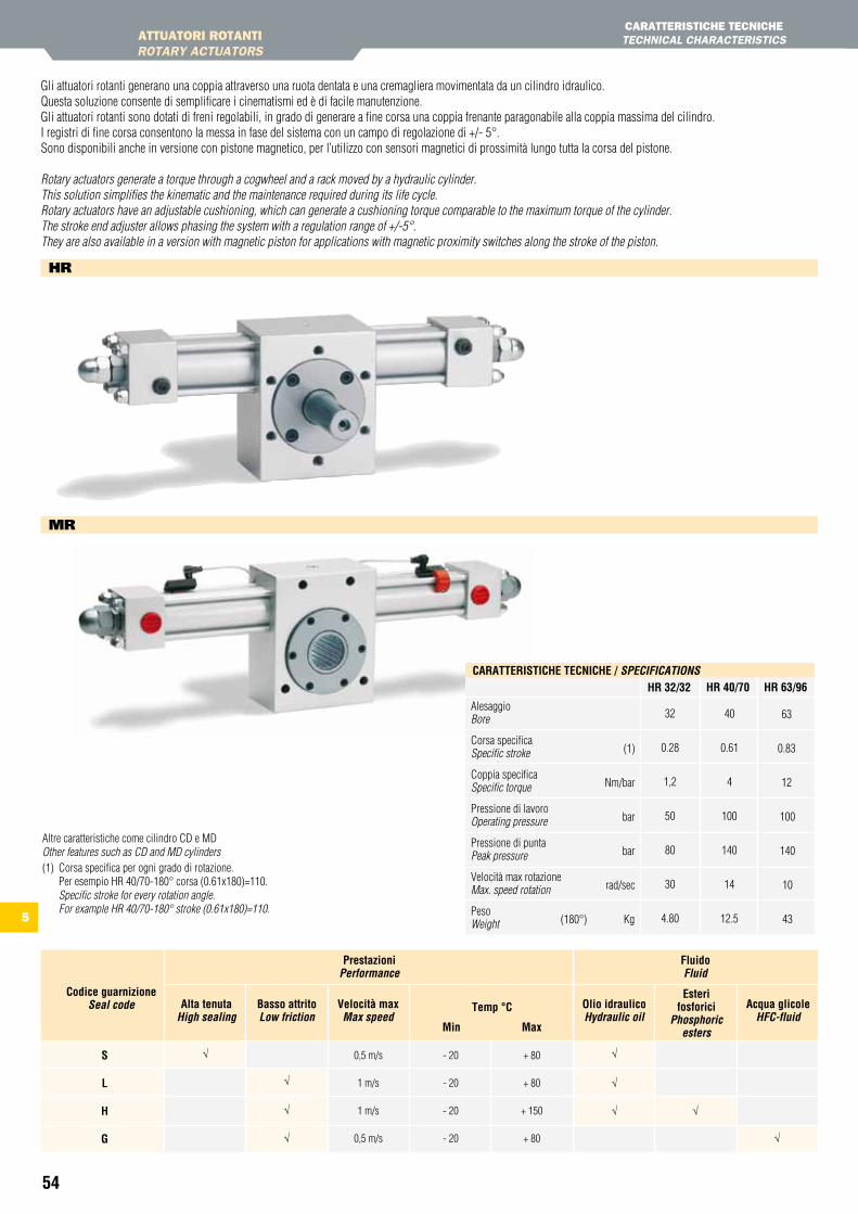
54
AttUAtORI ROtANtIROtARY ACtUAtORS
CARAttERIStICHE tECNICHEtECHNICAL CHARACtERIStICS
0,5 m/s
1 m/s
1 m/s
0,5 m/s
- 20
- 20
- 20
- 20
+ 80
+ 80
+ 150
+ 80
Codice guarnizioneSeal code alta tenuta
High sealingOlio idraulicoHydraulic oil
esterifosforici
phosphoric esters
acqua glicoleHfc-fluid
Basso attritoLow friction
Velocità maxMax speed
temp °C
Min Max
Prestazioniperformance
Fluidofluid
s L h G
√
√
√
√
√
√
√ √
√
hR
MR
Gli attuatori rotanti generano una coppia attraverso una ruota dentata e una cremagliera movimentata da un cilindro idraulico.Questa soluzione consente di semplificare i cinematismi ed è di facile manutenzione.Gli attuatori rotanti sono dotati di freni regolabili, in grado di generare a fine corsa una coppia frenante paragonabile alla coppia massima del cilindro.I registri di fine corsa consentono la messa in fase del sistema con un campo di regolazione di +/- 5°.Sono disponibili anche in versione con pistone magnetico, per l’utilizzo con sensori magnetici di prossimità lungo tutta la corsa del pistone. Rotary actuators generate a torque through a cogwheel and a rack moved by a hydraulic cylinder.This solution simplifies the kinematic and the maintenance required during its life cycle.Rotary actuators have an adjustable cushioning, which can generate a cushioning torque comparable to the maximum torque of the cylinder.The stroke end adjuster allows phasing the system with a regulation range of +/-5°.They are also available in a version with magnetic piston for applications with magnetic proximity switches along the stroke of the piston.
Alesaggio Bore
Corsa specifica Specific stroke
Coppia specifica Specific torque
Pressione di lavoro Operating pressure
Pressione di punta Peak pressure
Velocità max rotazione Max. speed rotation
Peso Weight
CaratteristiChe teCniChe / SpecificationS
32
0.28
1,2
50
80
30
4.80
hr 32/32 hr 40/70 hr 63/96
40
0.61
4
100
140
14
12.5
63
0.83
12
100
140
10
43
(1)
Nm/bar
bar
bar
rad/sec
(180°) Kg
Altre caratteristiche come cilindro CD e MD Other features such as CD and MD cylinders (1) Corsa specifica per ogni grado di rotazione.
Per esempio HR 40/70-180° corsa (0.61x180)=110. Specific stroke for every rotation angle. For example HR 40/70-180° stroke (0.61x180)=110.
5
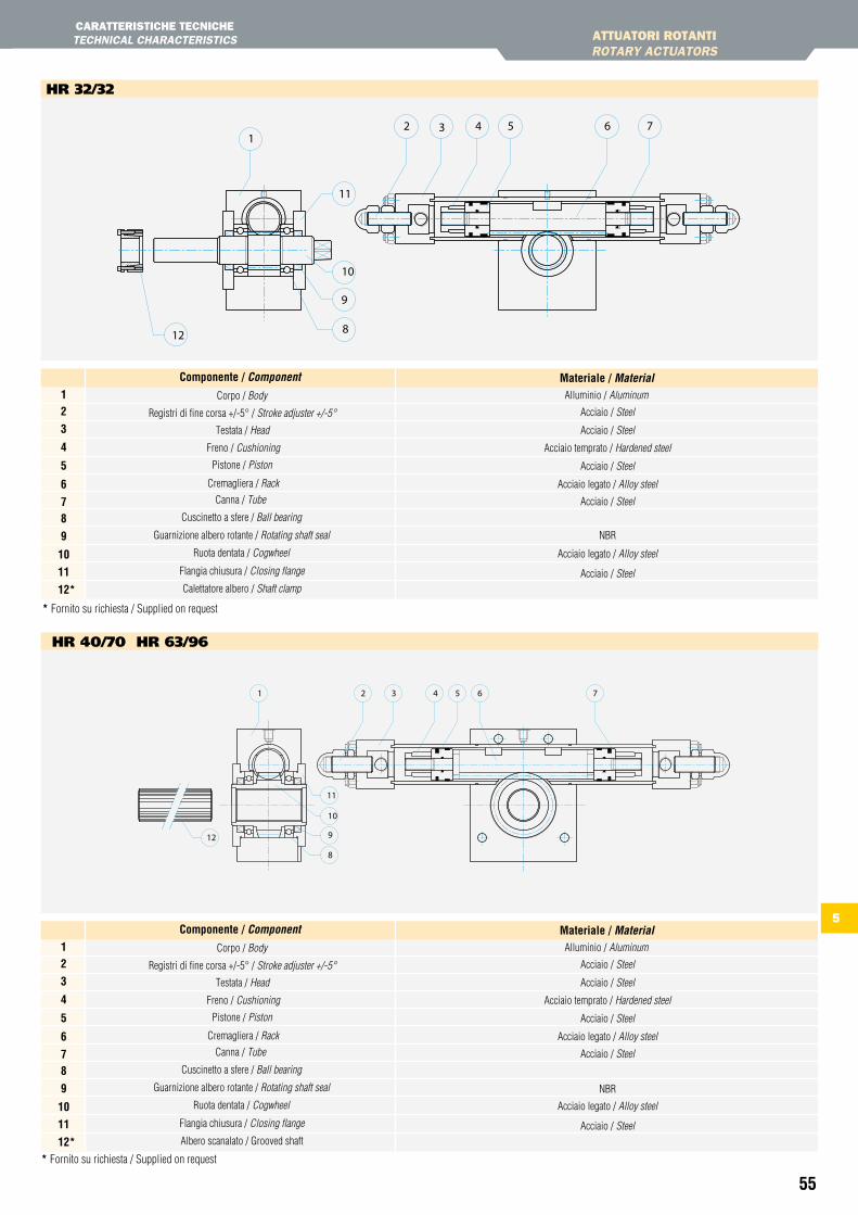
55
5
32 4 5 6
11
9
8
10
12
17
AttUAtORI ROtANtIROtARY ACtUAtORS
hR 32/32
2 3 4 5 61
10
8
9
11
12
7
hR 40/70 hR 63/96
* Fornito su richiesta / Supplied on request
* Fornito su richiesta / Supplied on request
CARAttERIStICHE tECNICHEtECHNICAL CHARACtERIStICS
Materiale / Material spec.Componente / componentCorpo / Body
Acciaio / Steel
Acciaio temprato / Hardened steel
Acciaio / Steel
Acciaio legato / Alloy steel
Acciaio / Steel
Acciaio legato / Alloy steel
NBR
Acciaio / Steel
Acciaio / Steel
Testata / Head
Registri di fine corsa +/-5° / Stroke adjuster +/-5°
Freno / Cushioning
Cremagliera / Rack
Canna / Tube
Cuscinetto a sfere / Ball bearing
Ruota dentata / Cogwheel
Flangia chiusura / Closing flange
Calettatore albero / Shaft clamp
Guarnizione albero rotante / Rotating shaft seal
Alluminio / Aluminum12
3
4
5
6
78
9
10
11
12*
Materiale / MaterialComponente / component
Pistone / Piston
Materiale / Material spec.Componente / componentCorpo / Body
Acciaio / Steel
Acciaio / Steel
Acciaio temprato / Hardened steel
Acciaio / Steel
Acciaio legato / Alloy steel
Acciaio / Steel
Acciaio legato / Alloy steel
Acciaio / Steel
Testata / Head
Registri di fine corsa +/-5° / Stroke adjuster +/-5°
Freno / Cushioning
Cremagliera / Rack
Canna / Tube
Cuscinetto a sfere / Ball bearing
Ruota dentata / Cogwheel
Flangia chiusura / Closing flange
Albero scanalato / Grooved shaft
Guarnizione albero rotante / Rotating shaft seal
Alluminio / Aluminum12
3
4
5
6
78
9
10
11
12*
Materiale / MaterialComponente / component
Pistone / Piston
NBR
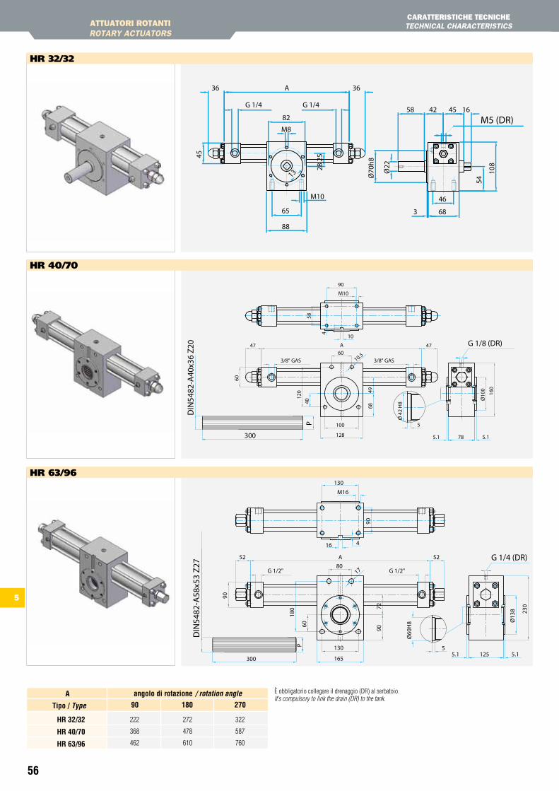
56
M5 (DR)
13
65
88
M10
3
46
68
108
54
58 1642 45
Ø70
h8
Ø22
G 1/4 G 1/4
A
82
M8
28.2
545
36 36
300
P
DIN
5482
-A40
x36
Z20
58
10
4
G 1/8 (DR)A47 4760
3/8" GAS
60
3/8" GAS10.5
120
40
90
128
M10
4968
Ø 4
2 H
8
5
78 5.15.1
Ø10
0
160
100
DIN
5482
-A58
x53
Z27
300
P
G 1/4 (DR)
1780A52
G 1/2" G 1/2"
52
90
Ø13
8 230
5.1125
Ø60
H8
5
165
9072
180
60
5.1
M16
130
90
4
130
16
è obbligatorio collegare il drenaggio (DR) al serbatoio.It’s compulsory to link the drain (DR) to the tank.
222
368
462
272
478
610
322
587
760
90 180 270
hr 32/32
hr 40/70
hr 63/96
tipo / type
angolo di rotazione / rotation anglea
AttUAtORI ROtANtIROtARY ACtUAtORS
CARAttERIStICHE tECNICHEtECHNICAL CHARACtERIStICS
hR 32/32
hR 40/70
hR 63/96
5
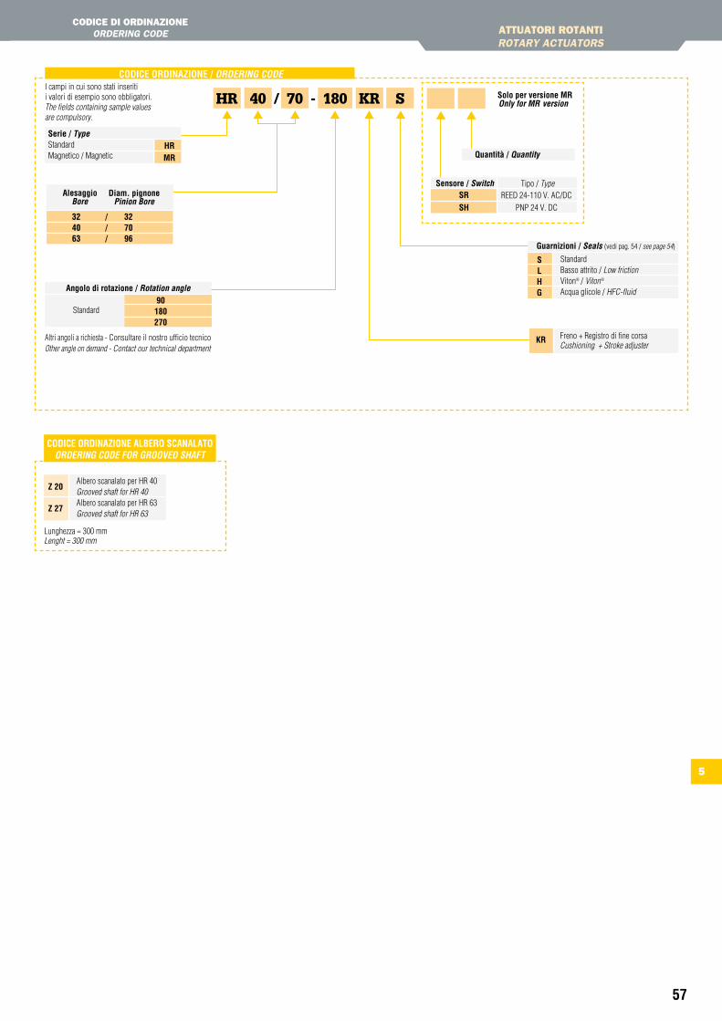
57
CODiCe OrDinaZiOne aLBerO sCanaLatO oRDeRinG coDe foR GRooVeD SHaft
Albero scanalato per HR 40 Grooved shaft for HR 40Albero scanalato per HR 63 Grooved shaft for HR 63
Z 20
Z 27
Lunghezza = 300 mm Lenght = 300 mm
HR KR40I campi in cui sono stati inseriti i valori di esempio sono obbligatori.The fields containing sample values are compulsory.
180
CODiCe OrDinaZiOne / oRDeRinG coDe
Standard90 180270
angolo di rotazione / Rotation angle
Altri angoli a richiesta - Consultare il nostro ufficio tecnicoOther angle on demand - Contact our technical department
70/ -
serie / typeStandardMagnetico / Magnetic
hrMr
Diam. pignonepinion Bore
32 4063
///
32 7096
alesaggioBore
Freno + Registro di fine corsa Cushioning + Stroke adjuster
Kr
Guarnizioni / Seals (vedi pag. 54 / see page 54)
Standard Basso attrito / Low frictionViton® / Viton® Acqua glicole / HFC-fluid
sLhG
S
AttUAtORI ROtANtIROtARY ACtUAtORS
CODICE DI ORDINAzIONEORDERING CODE
tECHNICAL CHARACtERIStICS
5
solo per versione Mronly for MR version
sensore / Switch Tipo / TypeREED 24-110 V. AC/DC
PNP 24 V. DC
srsh
Quantità / Quantity

59
tABELLE tECNICHEtECHNICAL tABLES
6
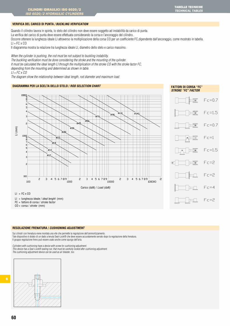
60
LI (m
m)
Carico (daN) / Load (daN)
LI = FC x CO
LI = lunghezza ideale / ideal lenght (mm)FC = fattore di corsa / stroke factorCO = corsa / stroke (mm)
FattOri Di COrsa “FC” StRoke “fc” factoR
DiaGraMMa Per La sCeLta DeLLO steLO / RoD SeLection cHaRt
CILINDRI IDRAULICI ISO 6020/2 ISO 6020/2 HYDRAULIC CYLINDERS
tABELLE tECNICHEtECHNICAL tABLES
VeriFiCa DeL CariCO Di Punta / BuckLinG VeRification
Quando il cilindro lavora in spinta, lo stelo del cilindro non deve essere soggetto ad instabilità da carico di punta.La verifica del carico di punta deve essere effettuata considerando la corsa e l’ancoraggio del cilindro.Occorre ottenere la lunghezza ideale LI attraverso la moltiplicazione della corsa CO per un coefficiente FC,dipendente dall’ancoraggio, come mostrato in tabella.LI = FC x COIl diagramma mostra la relazione tra lunghezza ideale LI, diametro dello stelo e carico massimo.
When the cylinder is pushing, the rod must be not subject to buckling instability.The buckling verification must be done considering the stroke and the mounting of the cylinder.It must be calculated the ideal length LI through the multiplication of the stroke CO with the stroke factor FC,depending from the mounting and determined as shown in table.LI = FC x COThe diagram show the relationship between ideal length, rod diameter and maximum load.
6
reGOLaZiOne Frenatura / cuSHioninG aDJuStMent
Sui cilindri con frenatura viene montata una vite che permette la regolazione dell’ammortizzamento.Tale dispositivo è dotato di un dado a tenuta Seal-Lock® che deve essere accuratamente serrato dopo la regolazione della frenatura.Il gruppo regolazione freno può essere usato anche come spurgo dell’aria.
Cylinders with cushioning have a device with screw for cushioning adjustment.This device has a Seal-Lock® sealing nut, that must be carefully locked after cushioning adjustment.The cushioning adjustment device can be used as air bleeder, too.
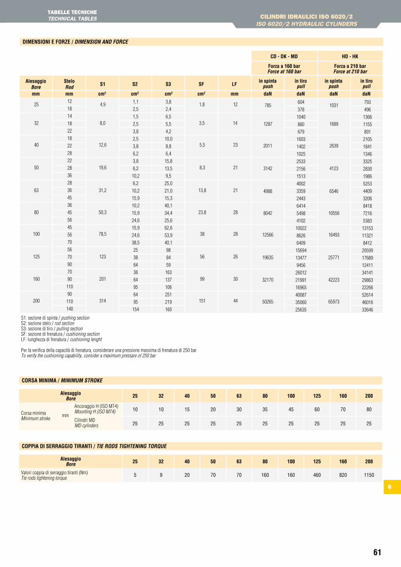
61
2011
3142
4988
8042
12566
19635
32170
50265
2639
4123
6546
10556
16493
25771
42223
65973
1287 1689
785 1031604
378
1040
880
679
1603
1402
1025
2533
2156
1513
4002
3359
2443
6414
5498
4102
10022
8626
6409
15694
13477
9456
26012
21991
16965
40087
35060
25635
793
496
1366
1155
891
2105
1841
1346
3325
2830
1986
5253
4409
3206
8418
7216
5383
13153
11321
8412
20599
17689
12411
34141
29863
22266
52614
46016
33646
alesaggioBore
steloRod
in spintapush
Forza a 160 barforce at 160 bar
CD - DK - MD hD - hK
Forza a 210 barforce at 210 bar
in spintapush
in tiropull
in tiropulls1 s2 s3 sF LF
mm mm cm² cm² cm² cm² mm dan dan dan dan
10
25
10
25
15
25
20
25
30
25
35
25
45
25
60
25
70
25
80
25
25alesaggioBore
Corsa minima mmMinimum stroke
Ancoraggio H (ISO MT4)Mounting H (ISO MT4)
Cilindri MDMD cylinders
32 40 50 63 80 100 125 160 200
CILINDRI IDRAULICI ISO 6020/2 ISO 6020/2 HYDRAULIC CYLINDERS
tABELLE tECNICHEtECHNICAL tABLES
DiMensiOni e FOrZe / DiMenSion anD foRce
COrsa MiniMa / MiniMuM StRoke
5 9 20 70 70 160 160 460 820 1150
25alesaggioBore
Valori coppia di serraggio tiranti (Nm)Tie rods tightening torque
32 40 50 63 80 100 125 160 200
COPPia Di serraGGiO tiranti / tie RoDS tiGHteninG toRQue
S1: sezione di spinta / pushing sectionS2: sezione stelo / rod sectionS3: sezione di tiro / pulling sectionSF: sezione di frenatura / cushioning sectionLF: lunghezza di frenatura / cushioning lenght
Per la verifica della capacità di frenatura, considerare una pressione massima di frenatura di 250 barTo verify the cushioning capability, consider a maximum pressare of 250 bar
6
25
32
40
50
63
80
100
125
160
200
12,6
19,6
31,2
50,3
78,5
123
201
314
5,5
8,3
13,8
23,8
38
56
99
151
23
21
21
28
28
26
30
44
8,0 3,5 14
4,9 1,8 1212
18
14
18
22
18
22
28
22
28
36
28
36
45
36
45
56
45
56
70
56
70
90
70
90
110
90
110
140
1,1
2,5
1,5
2,5
3,8
2,5
3,8
6,2
3,8
6,2
10,2
6,2
10,2
15,9
10,2
15,9
24,6
15,9
24,6
38,5
25
38
64
38
64
95
64
95
154
3,8
2,4
6,5
5,5
4,2
10,0
8,8
6,4
15,8
13,5
9,5
25,0
21,0
15,3
40,1
34,4
25,6
62,6
53,9
40,1
98
84
59
163
137
106
251
219
160
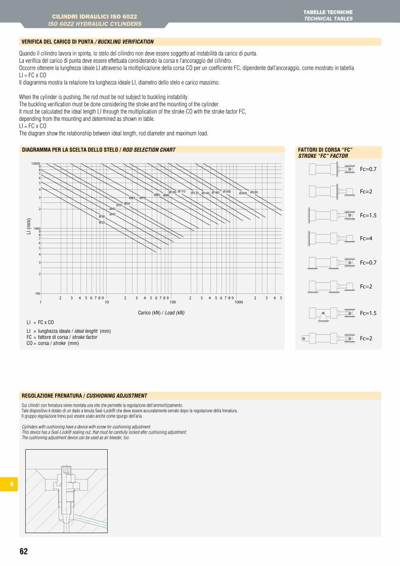
62
FattOri Di COrsa “FC” StRoke “fc” factoR
DiaGraMMa Per La sCeLta DeLLO steLO / RoD SeLection cHaRt
LI (m
m)
Carico (kN) / Load (kN)
LI = FC x CO
LI = lunghezza ideale / ideal lenght (mm)FC = fattore di corsa / stroke factorCO = corsa / stroke (mm)
CILINDRI IDRAULICI ISO 6022 ISO 6022 HYDRAULIC CYLINDERS
tABELLE tECNICHEtECHNICAL tABLES
Quando il cilindro lavora in spinta, lo stelo del cilindro non deve essere soggetto ad instabilità da carico di punta.La verifica del carico di punta deve essere effettuata considerando la corsa e l’ancoraggio del cilindro.Occorre ottenere la lunghezza ideale LI attraverso la moltiplicazione della corsa CO per un coefficiente FC, dipendente dall’ancoraggio, come mostrato in tabella.LI = FC x COIl diagramma mostra la relazione tra lunghezza ideale LI, diametro dello stelo e carico massimo.
When the cylinder is pushing, the rod must be not subject to buckling instability.The buckling verification must be done considering the stroke and the mounting of the cylinder.It must be calculated the ideal length LI through the multiplication of the stroke CO with the stroke factor FC,depending from the mounting and determined as shown in table.LI = FC x COThe diagram show the relationship between ideal length, rod diameter and maximum load.
VeriFiCa DeL CariCO Di Punta / BuckLinG VeRification
6
reGOLaZiOne Frenatura / cuSHioninG aDJuStMent
Sui cilindri con frenatura viene montata una vite che permette la regolazione dell’ammortizzamento.Tale dispositivo è dotato di un dado a tenuta Seal-Lock® che deve essere accuratamente serrato dopo la regolazione della frenatura.Il gruppo regolazione freno può essere usato anche come spurgo dell’aria.
Cylinders with cushioning have a device with screw for cushioning adjustment.This device has a Seal-Lock® sealing nut, that must be carefully locked after cushioning adjustment.The cushioning adjustment device can be used as air bleeder, too.
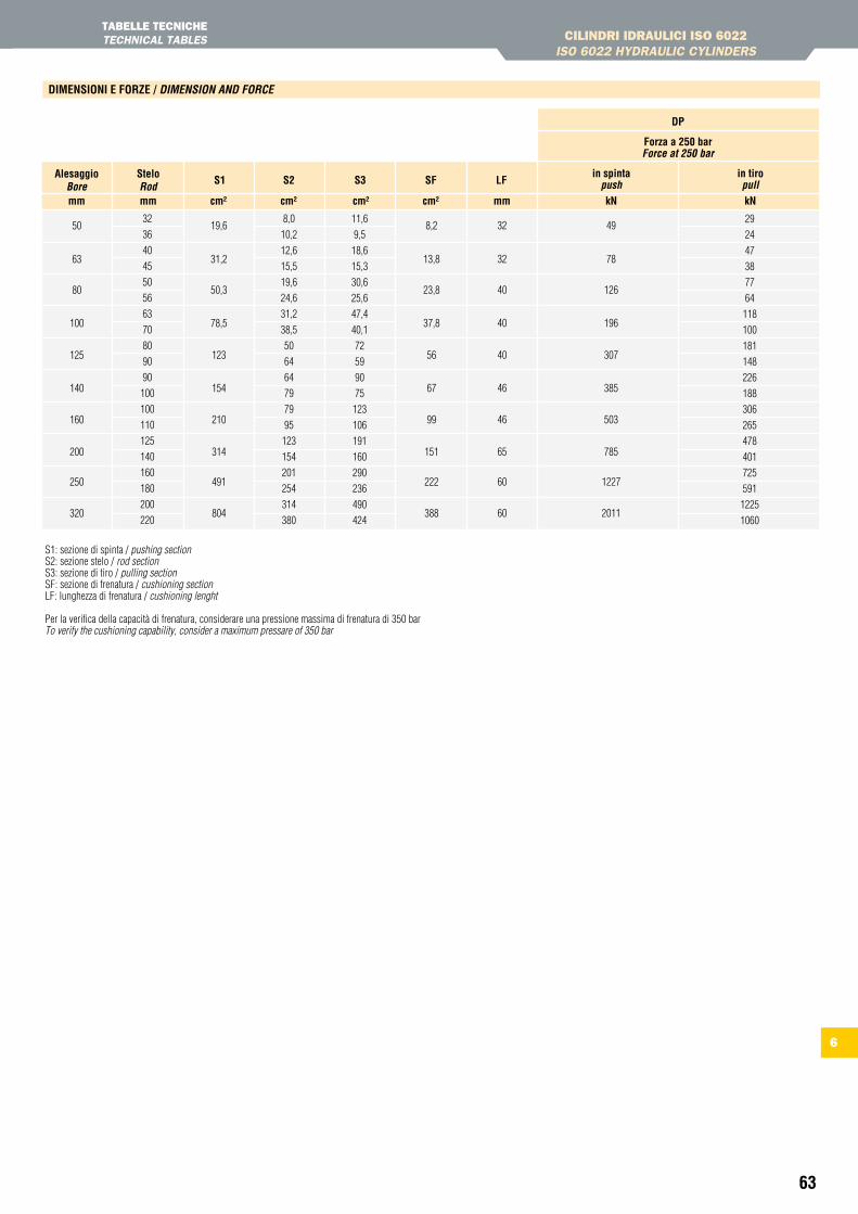
63
50
63
80
100
125
140
160
200
250
320
19,6
31,2
50,3
78,5
123
154
210
314
491
804
8,2
13,8
23,8
37,8
56
67
99
151
222
388
49
78
126
196
307
385
503
785
1227
2011
32
32
40
40
40
46
46
65
60
60
32
36
40
45
50
56
63
70
80
90
90
100
100
110
125
140
160
180
200
220
8,0
10,2
12,6
15,5
19,6
24,6
31,2
38,5
50
64
64
79
79
95
123
154
201
254
314
380
11,6
9,5
18,6
15,3
30,6
25,6
47,4
40,1
72
59
90
75
123
106
191
160
290
236
490
424
29
24
47
38
77
64
118
100
181
148
226
188
306
265
478
401
725
591
1225
1060
alesaggioBore
steloRod
in spintapush
Forza a 250 barforce at 250 bar
DP
in tiropulls1 s2 s3 sF LF
mm mm cm² cm² cm² cm² mm kn kn
DiMensiOni e FOrZe / DiMenSion anD foRce
CILINDRI IDRAULICI ISO 6022 ISO 6022 HYDRAULIC CYLINDERS
tABELLE tECNICHEtECHNICAL tABLES
6
S1: sezione di spinta / pushing sectionS2: sezione stelo / rod sectionS3: sezione di tiro / pulling sectionSF: sezione di frenatura / cushioning sectionLF: lunghezza di frenatura / cushioning lenght
Per la verifica della capacità di frenatura, considerare una pressione massima di frenatura di 350 barTo verify the cushioning capability, consider a maximum pressare of 350 bar