ci/fmt400-vts/vtcs-en sensyflow fmt400-vts, fmt400 …safety ci/fmt400-vts/vtcs-en sensyflow...
TRANSCRIPT
CI/FMT400-VTS/VTCS-EN Sensyflow FMT400-VTS, FMT400-VTCS
Commissioning Instructions
Thermal Mass Flowmeter Sensyflow FMT400-VTS, FMT400-VTCS

CI/FMT400-VTS/VTCS-EN Sensyflow FMT400-VTS, FMT400-VTCS EN - 1
Neu
Thermal Mass Flowmeter Sensyflow FMT400-VTS, FMT400-VTCS
Commissioning Instruction - EN CI/FMT400-VTS/VTCS-EN
07.2017
Rev. B
Original instruction
Manufacturer: ABB Automation Products GmbH Measurement & Analytics
Dransfelder Straße 2 D-37079 Göttingen Germany Tel.: +49 551 905-0 Fax: +49 551 905-777
Customer service center
Phone: +49 180 5 222 580 Fax: +49 621 381 931-29031 [email protected]
© Copyright 2017 by ABB Automation Products GmbH Subject to changes without notice
This document is protected by copyright. It assists the user in safe and efficient operation of the device. The contents of this document, whether whole or in part, may not be copied or reproduced without prior approval by the copyright holder.
Contents
Contents
2 - EN Sensyflow FMT400-VTS, FMT400-VTCS CI/FMT400-VTS/VTCS-EN
1 Safety .................................................................................................................................................................... 3
1.1 General information and notes for the reader ................................................................................................ 3 1.2 Intended use ................................................................................................................................................... 3
1.2.1 General information ................................................................................................................................. 4 1.2.2 Installing / Disassembling pipe components ........................................................................................... 5 1.2.3 Installing / Disassembling the flowmeter sensor ..................................................................................... 5
1.3 Target groups and qualifications .................................................................................................................... 5 1.4 Plates and symbols ........................................................................................................................................ 6
1.4.1 Safety- / warning symbols, note symbols ................................................................................................ 6 1.5 Name plate ..................................................................................................................................................... 7 1.6 Safety instructions for electrical installation ................................................................................................... 7
1.6.1 Safety instructions for operation ............................................................................................................. 7 1.7 Returning devices ........................................................................................................................................... 8 1.8 Integrated management system ..................................................................................................................... 8 1.9 Disposal .......................................................................................................................................................... 9
1.9.1 Information on WEEE Directive 2012/19/EU (Waste Electrical and Electronic Equipment) ................... 9 2 Use in potentially explosive atmospheres ........................................................................................................ 9 3 Design and function .......................................................................................................................................... 10 4 Mounting ............................................................................................................................................................ 11
4.1 Recommended steadying lengths according to DIN EN ISO 5167-1 .......................................................... 11 4.2 Installing the flowmeter sensor and pipe components ................................................................................. 12 4.3 Weld-on adapter for Sensyflow FMT400-VTS ............................................................................................. 13 4.4 Weld-on adapter with ball valve for Sensyflow FMT400-VTS ...................................................................... 15 4.5 Integrated hot tap fitting for Sensyflow FMT400-VTS .................................................................................. 17
4.5.1 Specifications for integrated hot tap fittings .......................................................................................... 18 4.5.2 Installing the wafer version .................................................................................................................... 18 4.5.3 Installing the weld-in version ................................................................................................................. 19 4.5.4 Installing the transmitter during actual operation .................................................................................. 20 4.5.5 Disassembling the transmitter during actual operation ......................................................................... 22
5 Electrical connections ...................................................................................................................................... 23 6 Commissioning .................................................................................................................................................. 24
6.1 Checking the installation .............................................................................................................................. 24 6.2 Connecting the power supply ....................................................................................................................... 24 6.3 Switching on ................................................................................................................................................. 24
7 Parameterization ................................................................................................................................................ 25 8 Error messages ................................................................................................................................................. 25 9 Appendix ............................................................................................................................................................ 26
9.1 Decommissioning and packaging ................................................................................................................ 26 9.2 Approvals and certifications ......................................................................................................................... 26
Safety
CI/FMT400-VTS/VTCS-EN Sensyflow FMT400-VTS, FMT400-VTCS EN - 3
1 Safety
1.1 General information and notes for the reader
You must read these instructions carefully prior to installing and commissioning the device.
These instructions are an important part of the product and must be kept for future reference.
These instructions are intended as an overview and do not contain detailed information on all designs for this product or every possible aspect of installation, operation and maintenance.
For additional information or if specific problems occur that are not discussed in these instructions, contact the manufacturer.
The content of these instructions is neither part of any previous or existing agreement, promise or legal relationship nor is it intended to change the same.
This product is built based on state-of-the-art technology and is operationally safe. It has been tested and left the factory in perfect working order from a safety perspective. The information in the manual must be observed and followed in order to maintain this state throughout the period of operation.
Modifications and repairs to the product may only be performed if expressly permitted by these instructions.
Only by observing all of the safety instructions and all safety/warning symbols in these instructions can optimum protection of both personnel and the environment, as well as safe and fault-free operation of the device, be ensured.
Information and symbols directly on the product must be observed. They may not be removed and must be fully legible at all times.
1.2 Intended use
Mass flow measurement of gases and gas mixtures in closed pipelines.
Can be used:
- As a plug-in sensor flanged into the pipe component in pipelines with nominal diameters DN 25 ... DN 200 (1 ... 8"),
- Via a weld-on adapter directly in pipelines of nominal diameter DN 100 (4") and above, as well as for non-circular cross-sections.
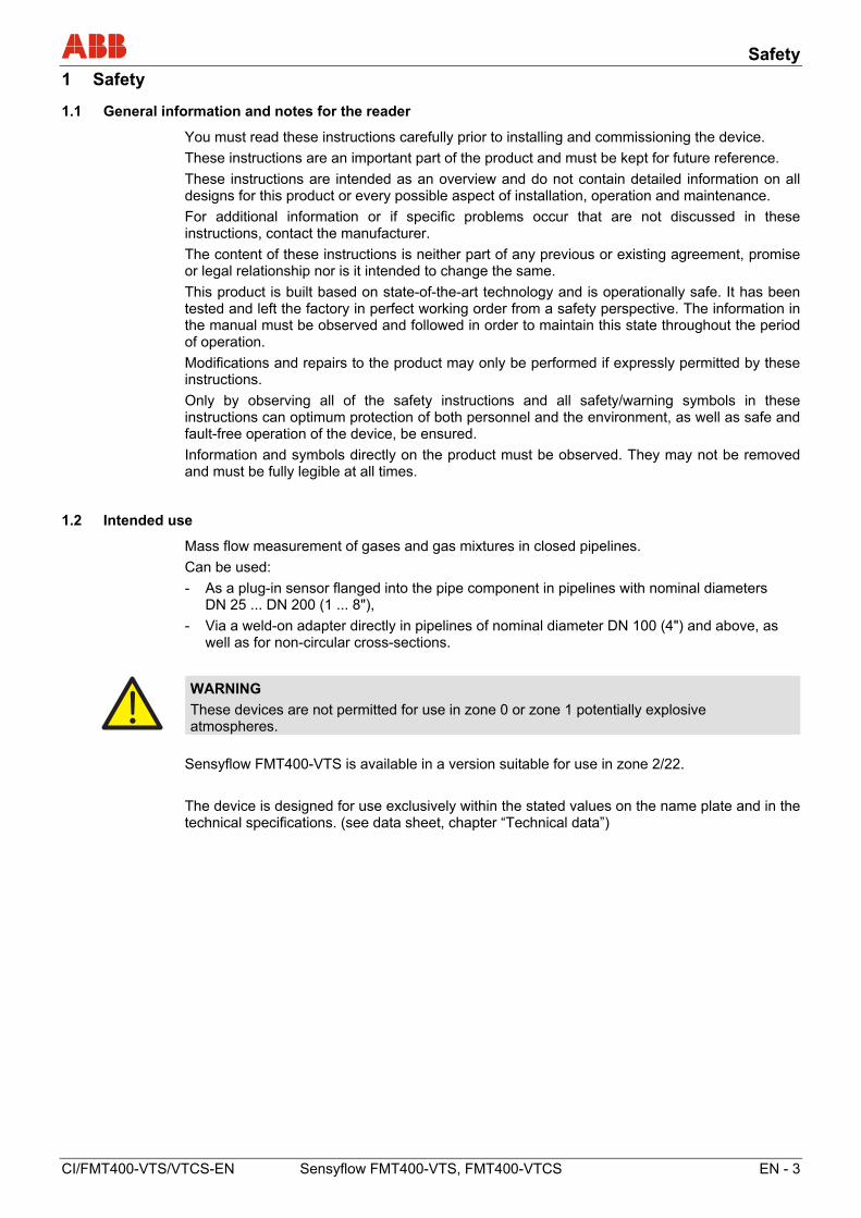
WARNING
These devices are not permitted for use in zone 0 or zone 1 potentially explosive atmospheres.
Sensyflow FMT400-VTS is available in a version suitable for use in zone 2/22.
The device is designed for use exclusively within the stated values on the name plate and in the technical specifications. (see data sheet, chapter “Technical data”)
Safety
4 - EN Sensyflow FMT400-VTS, FMT400-VTCS CI/FMT400-VTS/VTCS-EN
1.2.1 General information
• The device (including the pipe components) has been designed, produced and approved in accordance with Pressure Equipment Directive 2014/68/EU. The pipe components take the form of a
- Wafer design - Flange design with integrated measuring section - Weld-on adapter
The device may only be used in accordance with the application specified on the order confirmation; other operating conditions may prevent the device from functioning correctly, cause damage to it or even damage it beyond repair.
• Care must be taken to ensure that the measuring media used do not impair the chemical and physical properties of the components that come into contact with the fluids concerned.
• The threshold value for alternating load cycles corresponds to AD-2000 instruction sheet S1, Section 1.4 and is not calculated or checked by the manufacturer.
• The device should be included in any regular maintenance activities that are carried out on the entire system.
• The materials used must be checked by the user to ensure their suitability for the application concerned.
• The maximum operating conditions relating to pressure and temperature, as stated on the name plate / in the operating instructions, must not be exceeded.
• When installing and disassembling pipe components or flowmeter sensors, ensure that the pipeline has been depressurized. - Exception: If you are using a hot tap fitting.
• Before carrying out installation work on pipelines used to carry aggressive or toxic measuring media, media that may be classed as irritant, or other kinds of hazardous media, the fluids concerned must be adequately flushed out. Compliance with the relevant accident prevention regulations must also be ensured.
• If damaged, components must no longer be used. They must be taken out of circulation and sent to the manufacturer for repair.
• If disassembled components have come into contact with aggressive or toxic measuring media, media that may be classed as irritant, or other kinds of hazardous media, before being sent off they must be cleaned and then packed and labeled accordingly.
• If leaks occur at the measuring point, it must immediately be taken out of service.
• Defective gaskets or O-rings must be removed from use and must be replaced as a matter of urgency.
• The subsequent mechanical labeling or machining of pipe components and flowmeter sensors can result in damage and is prohibited. - Exception: Cutting to length and welding onto the pipeline in the case of weld-on
adapters.
Safety
CI/FMT400-VTS/VTCS-EN Sensyflow FMT400-VTS, FMT400-VTCS EN - 5
1.2.2 Installing / Disassembling pipe components
• During installation, it is important to ensure that the flow direction corresponds to the attached label.
• When welding the weld-on adapter, remember to observe the relevant welding instructions. The amount of heat introduced must be kept to an absolute minimum to prevent warping of the mounting flange's sealing surface.
• In the case of flanged connections, flat gaskets must be installed. These must be in perfect condition and resistant to the measuring media.
• Before installing pipe components or flowmeter sensors, check all components and gaskets for damage.
• Pipe components must not be installed under tension, otherwise the pipeline may be subjected to impermissible forces.
• When assembling the flanged connections, use screws that offer the required strength and dimensions.
• The screws must be tightened evenly and to the required torque.
• Once the pipe components have been installed, the insertion connection must be sealed by means of a blind flange plus gasket or by closing a shut-off device (if present).
1.2.3 Installing / Disassembling the flowmeter sensor
• Installation in the pipe component or weld-on adapter is only possible if the flowmeter sensor data matches the measuring point specifications.
• It is very important to use the O-ring supplied (not a flat gasket). This is resistant to measuring media and should be inserted in the groove provided in the pipe component flange.
• Take care not to damage the measuring elements when inserting the flowmeter sensor into the pipe component, as this is not permitted.
• The flowmeter sensor should be firmly bolted together with the flange of the insertion connection. The screws must be tightened evenly to the required torque.
• Torque for screws supplied: 87 Nm (unlubricated, without using spring washers).
• If you are using a pipe component with a hot tap fitting, you must check that the hot tap fitting is in the disassembly position before releasing the mounting screws.
1.3 Target groups and qualifications
Installation, commissioning, and maintenance of the product may only be performed by trained specialist personnel who have been authorized by the plant operator to do so. The specialist personnel must have read and understood the manual and comply with its instructions.
Prior to using corrosive and abrasive materials for measurement purposes, the operator must check the level of resistance of all parts coming into contact with the materials to be measured. ABB Automation Products GmbH will gladly support you in selecting the materials, but cannot accept any liability in doing so.
The operators must strictly observe the applicable national regulations with regards to installation, function tests, repairs, and maintenance of electrical products.
Safety
6 - EN Sensyflow FMT400-VTS, FMT400-VTCS CI/FMT400-VTS/VTCS-EN
1.4 Plates and symbols
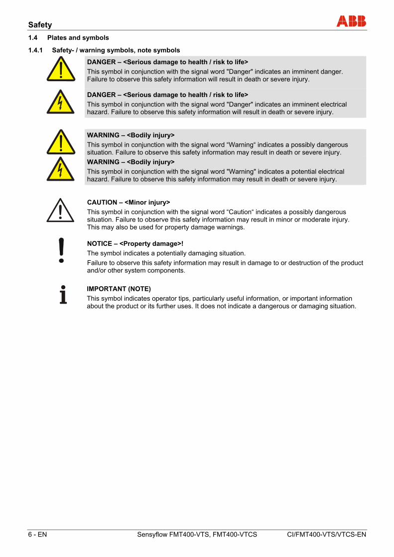
1.4.1 Safety- / warning symbols, note symbols
DANGER – <Serious damage to health / risk to life>
This symbol in conjunction with the signal word "Danger" indicates an imminent danger. Failure to observe this safety information will result in death or severe injury.
DANGER – <Serious damage to health / risk to life>
This symbol in conjunction with the signal word "Danger" indicates an imminent electrical hazard. Failure to observe this safety information will result in death or severe injury.
WARNING – <Bodily injury>
This symbol in conjunction with the signal word “Warning“ indicates a possibly dangerous situation. Failure to observe this safety information may result in death or severe injury.
WARNING – <Bodily injury>
This symbol in conjunction with the signal word "Warning" indicates a potential electrical hazard. Failure to observe this safety information may result in death or severe injury.
CAUTION – <Minor injury>
This symbol in conjunction with the signal word “Caution“ indicates a possibly dangerous situation. Failure to observe this safety information may result in minor or moderate injury. This may also be used for property damage warnings.
NOTICE – <Property damage>!
The symbol indicates a potentially damaging situation.
Failure to observe this safety information may result in damage to or destruction of the product and/or other system components.
IMPORTANT (NOTE)
This symbol indicates operator tips, particularly useful information, or important information about the product or its further uses. It does not indicate a dangerous or damaging situation.
Safety
CI/FMT400-VTS/VTCS-EN Sensyflow FMT400-VTS, FMT400-VTCS EN - 7
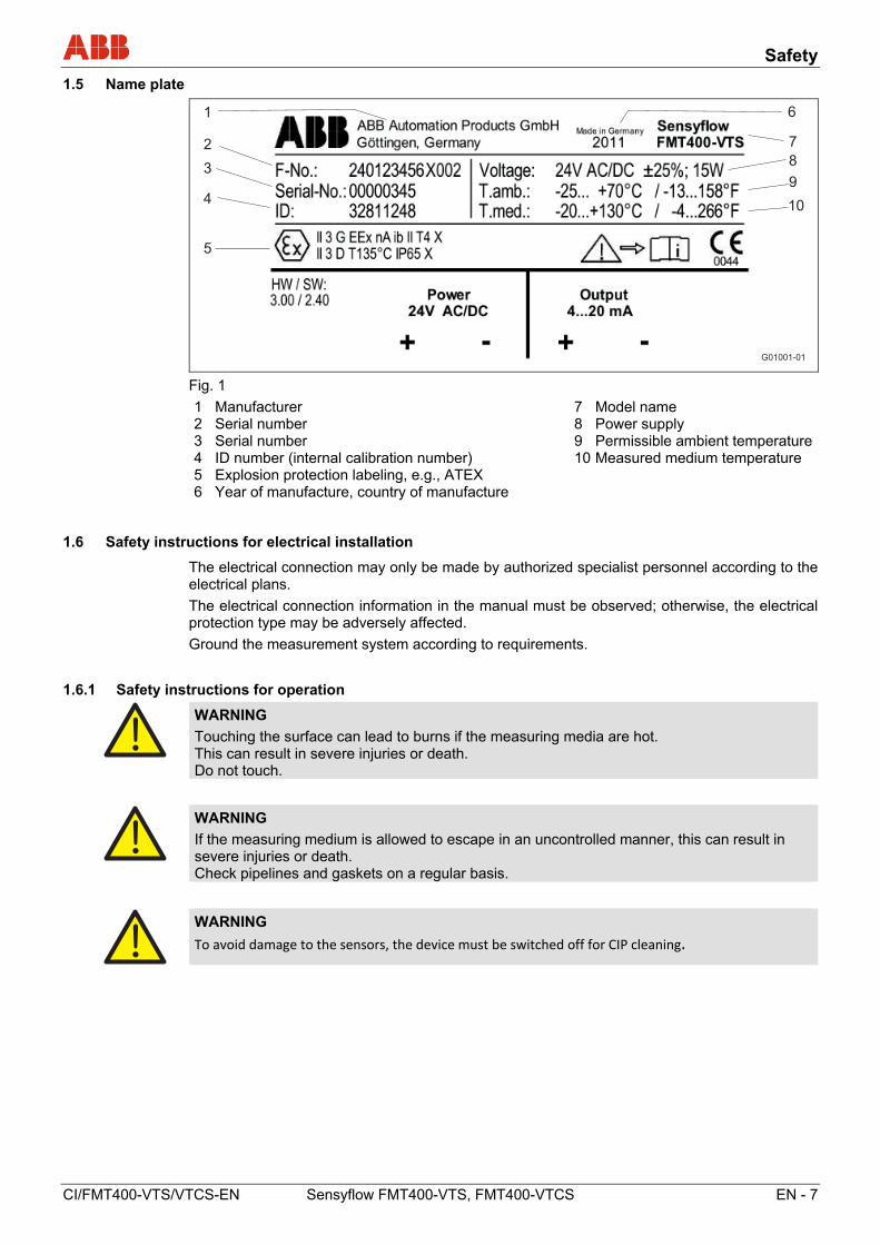
1.5 Name plate
G01001-01
3
2
1
4
5
6
7
8
9
10
Fig. 1
1 Manufacturer 2 Serial number 3 Serial number 4 ID number (internal calibration number) 5 Explosion protection labeling, e.g., ATEX 6 Year of manufacture, country of manufacture
7 Model name 8 Power supply 9 Permissible ambient temperature 10Measured medium temperature
1.6 Safety instructions for electrical installation
The electrical connection may only be made by authorized specialist personnel according to the electrical plans.
The electrical connection information in the manual must be observed; otherwise, the electrical protection type may be adversely affected.
Ground the measurement system according to requirements.
1.6.1 Safety instructions for operation
WARNING
Touching the surface can lead to burns if the measuring media are hot. This can result in severe injuries or death. Do not touch.
WARNING
If the measuring medium is allowed to escape in an uncontrolled manner, this can result in severe injuries or death. Check pipelines and gaskets on a regular basis.
WARNING
To avoid damage to the sensors, the device must be switched off for CIP cleaning.
Safety
8 - EN Sensyflow FMT400-VTS, FMT400-VTCS CI/FMT400-VTS/VTCS-EN
1.7 Returning devices
Use the original packaging or a secure transport container of an appropriate type if you need to return the device for repair or recalibration purposes. Fill out the return form (see the Appendix) and include this with the device.
The EU Directive governing hazardous materials dictates that the owners of any hazardous waste are also responsible for disposing of it.
All devices delivered to the manufacturer must be free from any hazardous materials (acids, alkalis, solvents, etc.).
Pipe components and flowmeter sensors contain hollow spaces. If they have been used in conjunction with hazardous materials, they must therefore be rinsed out in order to neutralize any such substances.
The owner will be charged for any costs incurred as a result of the device not having been adequately cleaned or of any failure to dispose of hazardous materials. The manufacturer reserves the right to return a contaminated device.
Please
Please contact Customer Center Service acc. to page 1 for nearest service location.
1.8 Integrated management system
ABB Automation Products GmbH operates an integrated management system, consisting of:
• Quality management system to ISO 9001
• Environmental management system to ISO 14001
• Occupational health and safety management system to BS OHSAS 18001 and
• Data and information protection management system
Environmental awareness is an important part of our company policy.
Our products and solutions are intended to have a minimal impact on the environment and on people during manufacturing, storage, transport, use, and disposal.
This includes the environmentally-friendly use of natural resources. We conducts an open dialog with the public through our publications.
Use in potentially explosive atmospheres
CI/FMT400-VTS/VTCS-EN Sensyflow FMT400-VTS, FMT400-VTCS EN - 9
1.9 Disposal
This product is manufactured from materials that can be reused by specialist recycling companies.
1.9.1 Information on WEEE Directive 2012/19/EU (Waste Electrical and Electronic Equipment)
This product is not subject to WEEE Directive 2012/19/EU or relevant national laws (e.g., ElektroG in Germany).
The product must be disposed of at a specialist recycling facility. Do not use municipal garbage collection points. According to the WEEE Directive 2012/19/EU, only products used in private applications may be disposed of at municipal garbage facilities. Proper disposal prevents negative effects on people and the environment, and supports the reuse of valuable raw materials.
If it is not possible to dispose of old equipment properly, ABB Service can accept and dispose of returns for a fee.
2 Use in potentially explosive atmospheres
The device is available in a hazardous area design for zone 2 and zone 22 and is supplied with a manufacturer's declaration in accordance with ATEX. When operating these devices in the approved range, only the data and information contained in this manufacturer's declaration shall apply (see Appendix).
WARNING - General risks!
It is not permitted to use the devices in zone 1 / 21 or in zone 0 / 20.
Design and function
10 - EN Sensyflow FMT400-VTS, FMT400-VTCS CI/FMT400-VTS/VTCS-EN
3 Design and function
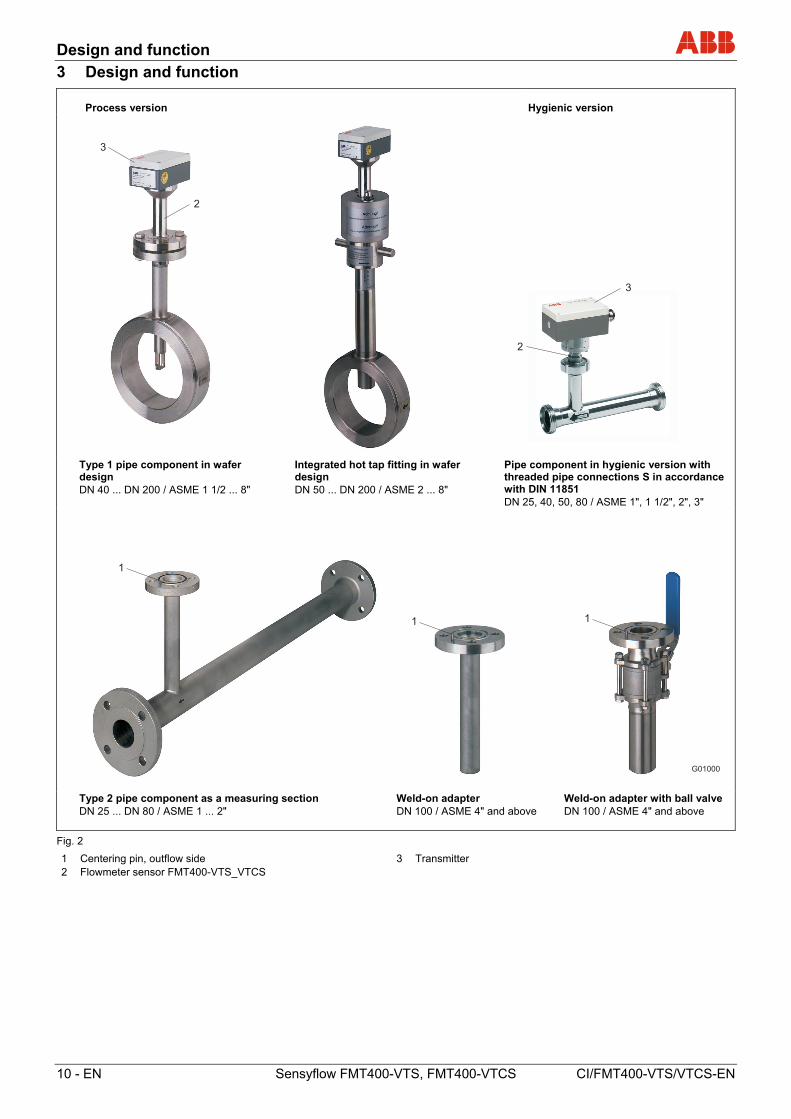
Process version Hygienic version
2
2
3
3
Type 1 pipe component in wafer design DN 40 ... DN 200 / ASME 1 1/2 ... 8"
Integrated hot tap fitting in wafer design DN 50 ... DN 200 / ASME 2 ... 8"
Pipe component in hygienic version with threaded pipe connections S in accordance with DIN 11851 DN 25, 40, 50, 80 / ASME 1", 1 1/2", 2", 3"
G01000
11
1
Type 2 pipe component as a measuring section DN 25 ... DN 80 / ASME 1 ... 2"
Weld-on adapter DN 100 / ASME 4" and above
Weld-on adapter with ball valve DN 100 / ASME 4" and above
Fig. 2
1 Centering pin, outflow side 2 Flowmeter sensor FMT400-VTS_VTCS
3 Transmitter
Mounting
CI/FMT400-VTS/VTCS-EN Sensyflow FMT400-VTS, FMT400-VTCS EN - 11
4 Mounting
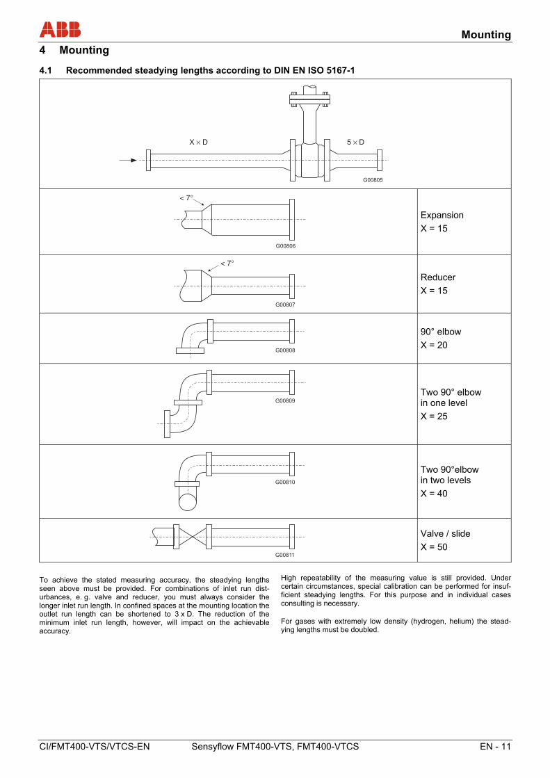
4.1 Recommended steadying lengths according to DIN EN ISO 5167-1
G00805
X D× 5 D×
G00806
< 7°
Expansion
X = 15
< 7°
G00807
Reducer
X = 15
G00808
90° elbow
X = 20
G00809
Two 90° elbow in one level
X = 25
G00810
Two 90°elbow in two levels
X = 40
G00811
Valve / slide
X = 50
Change from one to two columns
To achieve the stated measuring accuracy, the steadying lengths seen above must be provided. For combinations of inlet run dist-urbances, e. g. valve and reducer, you must always consider the longer inlet run length. In confined spaces at the mounting location the outlet run length can be shortened to 3 x D. The reduction of the minimum inlet run length, however, will impact on the achievable accuracy.
High repeatability of the measuring value is still provided. Under certain circumstances, special calibration can be performed for insuf-ficient steadying lengths. For this purpose and in individual cases consulting is necessary. For gases with extremely low density (hydrogen, helium) the stead-ying lengths must be doubled.
Change from one to two columns
Mounting
12 - EN Sensyflow FMT400-VTS, FMT400-VTCS CI/FMT400-VTS/VTCS-EN
4.2 Installing the flowmeter sensor and pipe components
Pipe components can be supplied in a wafer design (type 1) or as a measuring section (type 2) (see Fig. 2) and should be installed stress-free (without torsion / bending stress) in the pipeline along with the appropriate gaskets.
Gaskets must not alter the cross-section of the opening in the pipeline and must ensure complete tightness once the flowmeter sensor and pipe component have been installed. It must be ensured that the gaskets are compatible with the measured medium and the associated temperature.
In the case of the type 1 pipe component (wafer design), care must be taken to ensure centered installation. The internal diameters of the pipe and flange must match exactly. Any differences in levels or edges, or untidy weld seams, will reduce the measuring accuracy.
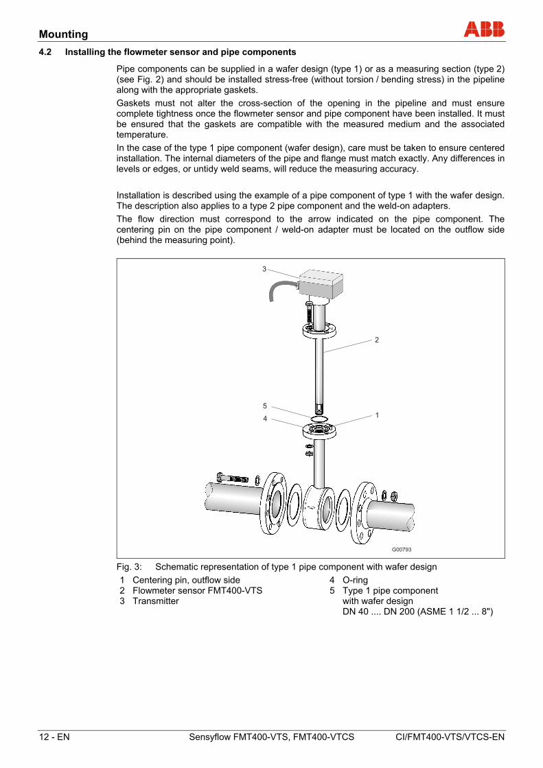
Installation is described using the example of a pipe component of type 1 with the wafer design. The description also applies to a type 2 pipe component and the weld-on adapters.
The flow direction must correspond to the arrow indicated on the pipe component. The centering pin on the pipe component / weld-on adapter must be located on the outflow side (behind the measuring point).
G00793
2
1
5
4
3
Fig. 3: Schematic representation of type 1 pipe component with wafer design
1 Centering pin, outflow side 2 Flowmeter sensor FMT400-VTS 3 Transmitter
4 O-ring 5 Type 1 pipe component with wafer design DN 40 .... DN 200 (ASME 1 1/2 ... 8")
Mounting
CI/FMT400-VTS/VTCS-EN Sensyflow FMT400-VTS, FMT400-VTCS EN - 13
Installing the flowmeter sensor
1. Insert the O-ring (55 x 3 mm [2.16 x 0.12 inches]) supplied into the groove provided for this purpose.
2. Push the flowmeter sensor into the adapter and screw into place.
3. All flange screws must be installed properly.
Before disassembling the flowmeter sensor, ensure that the pipeline has been depressurized.
WARNING
If you attempt to install / disassemble the flowmeter sensor at an absolute pressure of more than 1.1 bar, it could fly out, resulting in severe injuries or death. Use the integrated hot tap fitting.
WARNING
Attempting the installation / disassembly process at high temperatures or when using hazardous gases can result in severe injuries or death. Use the integrated hot tap fitting.
IMPORTANT (NOTE)
In the case of the type 1 pipe component (wafer design) with ball valve, flowmeter sensors with a length of 425 mm (16.73 inches) must be used for nominal diameters of DN 125, DN 150, and DN 200 / ASME 6" and ASME 8".
4.3 Weld-on adapter for Sensyflow FMT400-VTS
If you are installing the flowmeter sensor in larger nominal diameters or non-circular cable cross sections, you must observe the following points when attaching the weld-on adapter to the pipeline:
1 The length of the weld-on adapter must be equal to L once it has been welded on (see Figures 7 and 8)
L = h – 1/2 x Ø Dexternal where h = 263 mm (10.35 inches), 425 mm (16.73 inches) or
775 mm (30.51 inches) (flowmeter sensor lengths)
- Shorten the length of the weld-on adapter as appropriate before welding it on. Once it has been welded on, the weld-on adapter may extend into the pipeline by several mm (max. 10 mm [0.39 inches]).
- Observe thickness of pipeline wall and degree of shrinkage when welding on.
- The distance h from the upper edge of the adapter flange to the the pipe central axis must be within a tolerance of ± 2 mm (0.08 inches).
2 It is essential to maintain a right angle to the pipe axis (max. tolerance: 2°).
3 The adapter centering pin must be aligned with the pipe axis in the flow direction (outflow side, behind the measuring point).
4 Once welding is complete, there must be a passage of at least 28 mm (1.10 inches) free for the purpose of mounting the flowmeter sensor; drill to create if necessary.
5 Installing the flowmeter sensor:
- Insert the O-ring (55 x 3 mm [2.16 x 0.12 inches]) supplied into the groove provided for this purpose.
- Push the flowmeter sensor into the adapter and screw into place.
Mounting
14 - EN Sensyflow FMT400-VTS, FMT400-VTCS CI/FMT400-VTS/VTCS-EN
G00802
min. 28 (1,10)h
L
Ø 33,7 (1,33)
450
(17,7
2)
Ø d
ØD
2
311
← Direction of flow
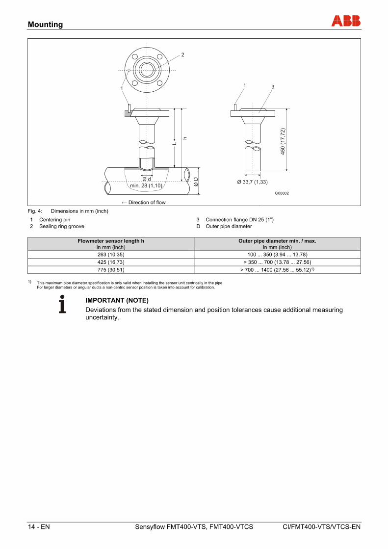
Fig. 4: Dimensions in mm (inch)
1 Centering pin 2 Sealing ring groove
3 Connection flange DN 25 (1”) D Outer pipe diameter
Flowmeter sensor length h in mm (inch)
Outer pipe diameter min. / max. in mm (inch)
263 (10.35) 100 ... 350 (3.94 ... 13.78)
425 (16.73) > 350 ... 700 (13.78 ... 27.56)
775 (30.51) > 700 ... 1400 (27.56 ... 55.12)1) 1) This maximum pipe diameter specification is only valid when installing the sensor unit centrically in the pipe.
For larger diameters or angular ducts a non-centric sensor position is taken into account for calibration.
IMPORTANT (NOTE)
Deviations from the stated dimension and position tolerances cause additional measuring uncertainty.
Mounting
CI/FMT400-VTS/VTCS-EN Sensyflow FMT400-VTS, FMT400-VTCS EN - 15
4.4 Weld-on adapter with ball valve for Sensyflow FMT400-VTS
Versions featuring a ball valve enable the flowmeter sensor to be installed and disassembled at low gauge pressures in the pipeline with minimal gas leakage.
Install the weld-on adapter as described in Section 4.3.
WARNING
During welding, the gaskets in the ball valve may overheat. This can lead to the measuring medium escaping in an uncontrolled manner. This can result in severe injuries or death. Disassemble the ball valve prior to welding.
Before the flowmeter sensor is installed, the ball valve must be opened completely. Then, the flowmeter sensor can be installed along with the appropriate gasket and screwed into place.
Before disassembling the flowmeter sensor, ensure that the pipeline has been depressurized. Then, you can release the screws on the flange, remove the flowmeter sensor and close the ball valve.
NOTICE - Potential damage to parts!
Closing the ball valve before you remove the flowmeter sensor can seriously damage the protective cage or the sensor elements. Do not close the ball valve until the flowmeter sensor has been removed.
Mounting
16 - EN Sensyflow FMT400-VTS, FMT400-VTCS CI/FMT400-VTS/VTCS-EN
G00803
540
(21,2
6)
Ø 48,3 (1,90)
h
Lmin. 28 (1,10)
Ø d
ØD
2
131
← Direction of flow
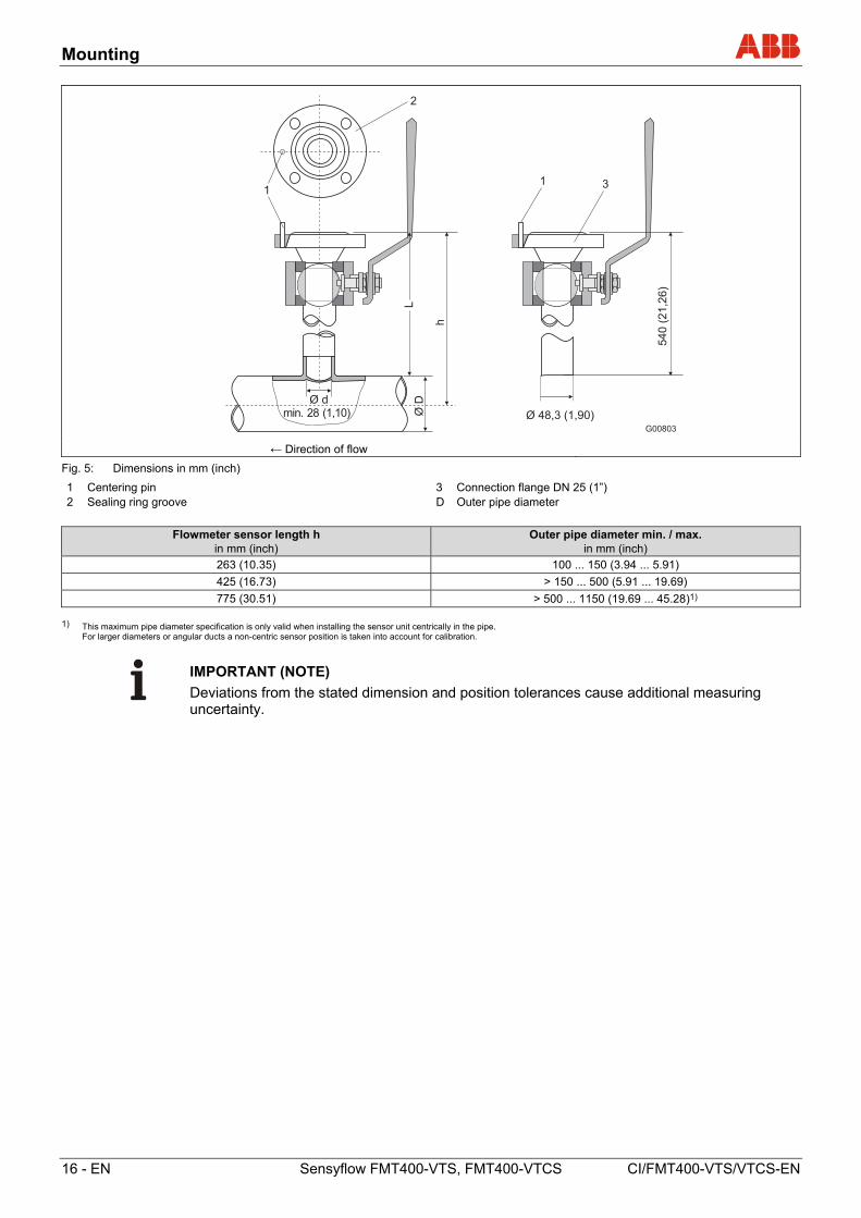
Fig. 5: Dimensions in mm (inch)
1 Centering pin 2 Sealing ring groove
3 Connection flange DN 25 (1”) D Outer pipe diameter
Flowmeter sensor length h in mm (inch)
Outer pipe diameter min. / max. in mm (inch)
263 (10.35) 100 ... 150 (3.94 ... 5.91)
425 (16.73) > 150 ... 500 (5.91 ... 19.69)
775 (30.51) > 500 ... 1150 (19.69 ... 45.28)1) 1) This maximum pipe diameter specification is only valid when installing the sensor unit centrically in the pipe.
For larger diameters or angular ducts a non-centric sensor position is taken into account for calibration.
IMPORTANT (NOTE)
Deviations from the stated dimension and position tolerances cause additional measuring uncertainty.
Mounting
CI/FMT400-VTS/VTCS-EN Sensyflow FMT400-VTS, FMT400-VTCS EN - 17
4.5 Integrated hot tap fitting for Sensyflow FMT400-VTS
Water flange version – sensor unit in exchange position
Weld-in version – sensor unit in measuring position
G00812
h=
425
(16,7
3)
50
(1,9
7)
Ø 50 (1,97)
Hub
str
oke
/m
m
20
10
30
40
0 - CLOSE - ZU
50 -OPEN -MESSEN
1
2
3
4
5
6
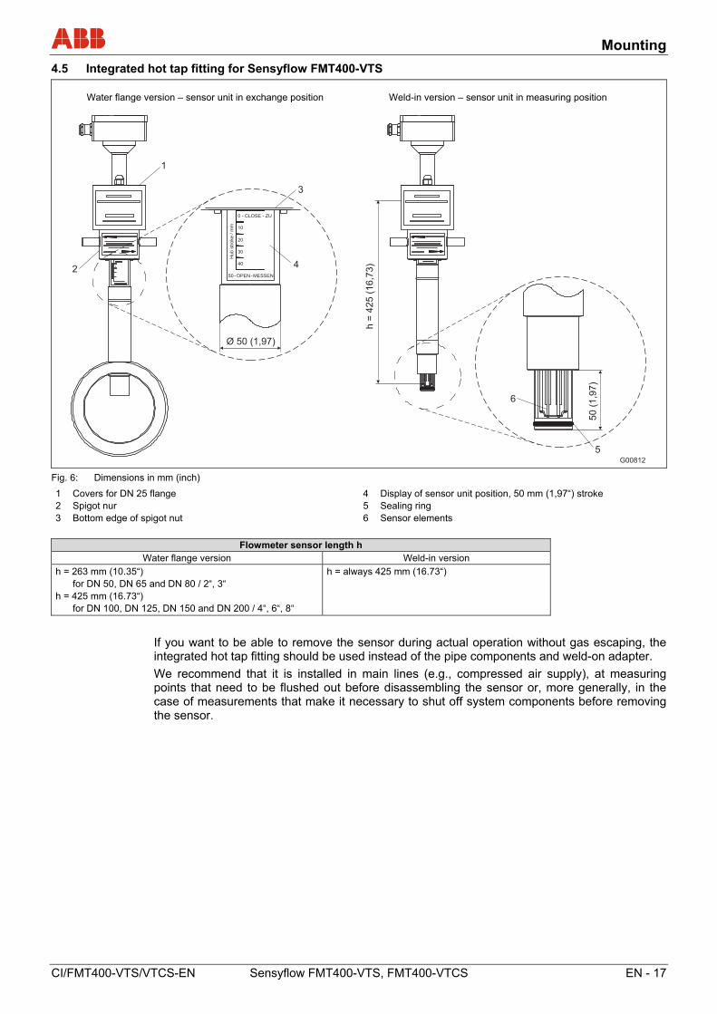
Fig. 6: Dimensions in mm (inch)
1 Covers for DN 25 flange 2 Spigot nur 3 Bottom edge of spigot nut
4 Display of sensor unit position, 50 mm (1,97“) stroke 5 Sealing ring 6 Sensor elements
Flowmeter sensor length h Water flange version Weld-in version
h = 263 mm (10.35“) for DN 50, DN 65 and DN 80 / 2“, 3“ h = 425 mm (16.73“) for DN 100, DN 125, DN 150 and DN 200 / 4“, 6“, 8“
h = always 425 mm (16.73“)
If you want to be able to remove the sensor during actual operation without gas escaping, the integrated hot tap fitting should be used instead of the pipe components and weld-on adapter.
We recommend that it is installed in main lines (e.g., compressed air supply), at measuring points that need to be flushed out before disassembling the sensor or, more generally, in the case of measurements that make it necessary to shut off system components before removing the sensor.
Mounting
18 - EN Sensyflow FMT400-VTS, FMT400-VTCS CI/FMT400-VTS/VTCS-EN
4.5.1 Specifications for integrated hot tap fittings
The hot tap fitting is designed for pressure loads of max. 16 bar abs. To ensure interchangeability with standard pipe components (type 1), the wafer version (Fig. 8) has been developed for DN 50 and DN 80 DIN flanges with a pressure stage of PN 40. In the case of the DN 65 version with a pressure stage of PN 16, you should use connection flanges with 4 screw holes. Imperial versions 2 ... 8“ designed for connection flange ASME B16.5 Cl.150 only. For suitable flowmeter sensor lengths, see Fig. 6.
G00815
0
2
4
6
8
10
12
14
16
18
0 (32) 50 (122) 100 (212) 150 (302) 200 (392) 250 (482)T [°C] (°F)
0
29
58
87
116
145
174
203
232
261
p[p
si]
p[b
ar]
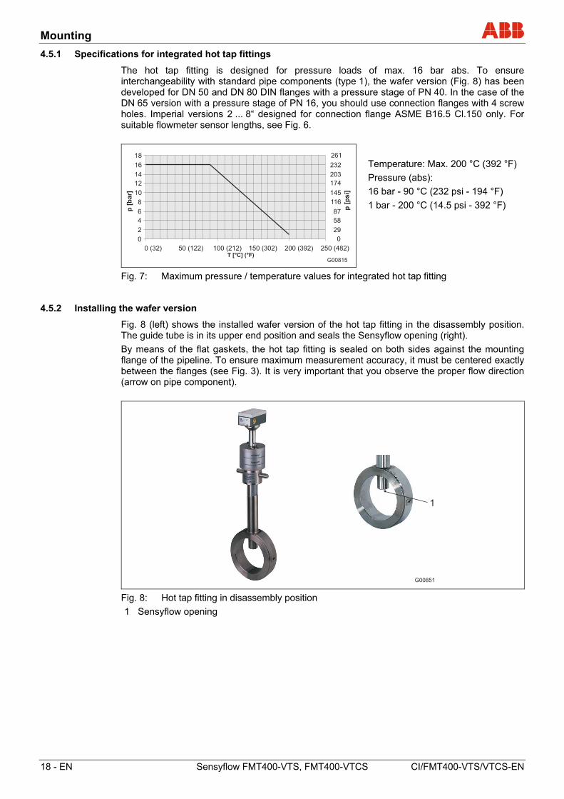
Temperature: Max. 200 °C (392 °F)
Pressure (abs):
16 bar - 90 °C (232 psi - 194 °F)
1 bar - 200 °C (14.5 psi - 392 °F)
Fig. 7: Maximum pressure / temperature values for integrated hot tap fitting
4.5.2 Installing the wafer version
Fig. 8 (left) shows the installed wafer version of the hot tap fitting in the disassembly position. The guide tube is in its upper end position and seals the Sensyflow opening (right).
By means of the flat gaskets, the hot tap fitting is sealed on both sides against the mounting flange of the pipeline. To ensure maximum measurement accuracy, it must be centered exactly between the flanges (see Fig. 3). It is very important that you observe the proper flow direction (arrow on pipe component).
G00851
1
Fig. 8: Hot tap fitting in disassembly position
1 Sensyflow opening
Mounting
CI/FMT400-VTS/VTCS-EN Sensyflow FMT400-VTS, FMT400-VTCS EN - 19
4.5.3 Installing the weld-in version
The weld-in version of the hot tap fitting is available in two overall lengths:
- For nominal diameters DN 100 ... DN 125 (4 ... 5") and
- For nominal diameters DN 150 ... DN 300 (6 ... 12")
The flowmeter sensor length is h = 425 mm (16.73 inches) in both cases.
The installation depth depends on the pipe diameter and is calculated individually.
WARNING
Do not shorten hot tap fitting components or interfere with the design. This can lead to the measuring medium escaping in an uncontrolled manner. This can result in severe injuries or death.
G00852
X h
Ø50
Y
28
48
(2)
(1,1
)
(1,9
)
1
2
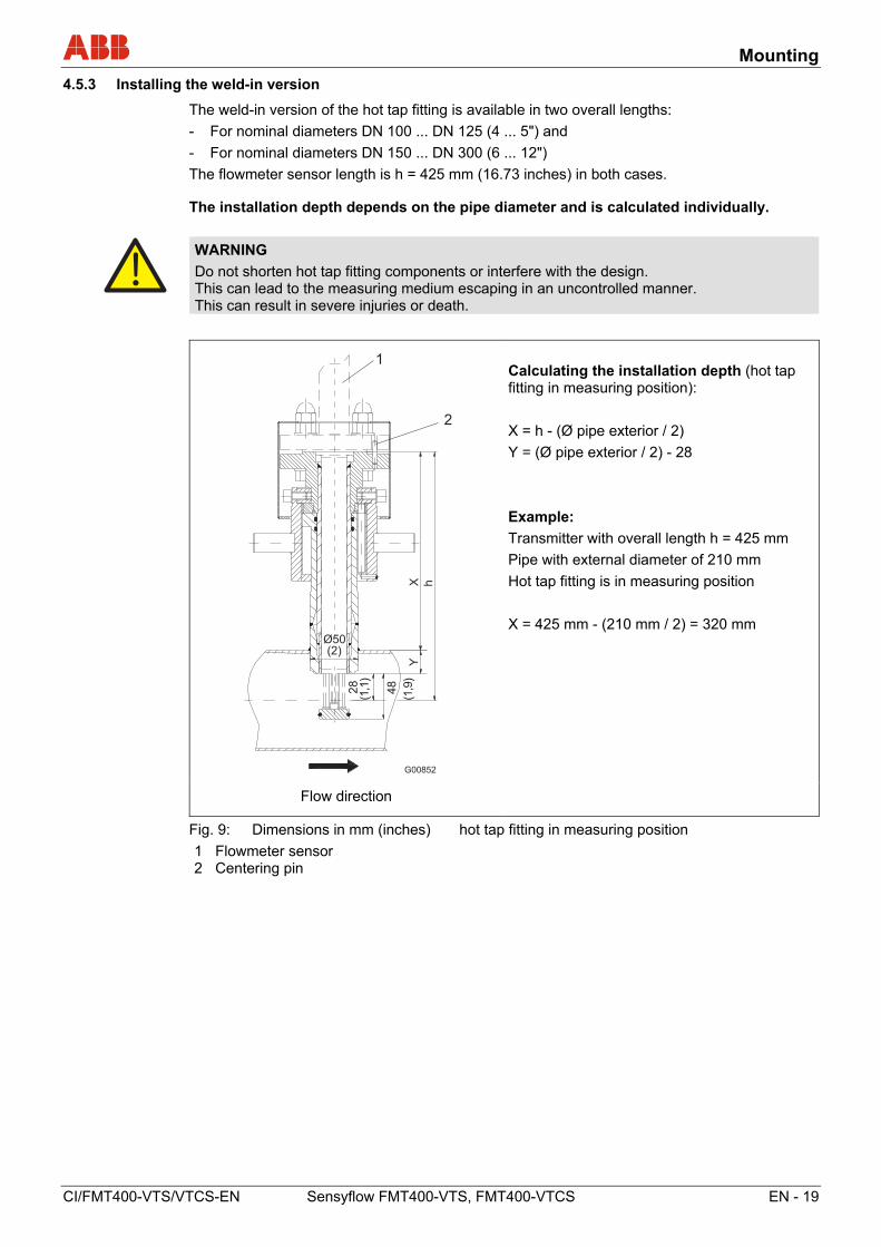
Calculating the installation depth (hot tap fitting in measuring position):
X = h - (Ø pipe exterior / 2)
Y = (Ø pipe exterior / 2) - 28
Example:
Transmitter with overall length h = 425 mm
Pipe with external diameter of 210 mm
Hot tap fitting is in measuring position
X = 425 mm - (210 mm / 2) = 320 mm
Flow direction
Fig. 9: Dimensions in mm (inches) hot tap fitting in measuring position
1 Flowmeter sensor 2 Centering pin
Mounting
20 - EN Sensyflow FMT400-VTS, FMT400-VTCS CI/FMT400-VTS/VTCS-EN
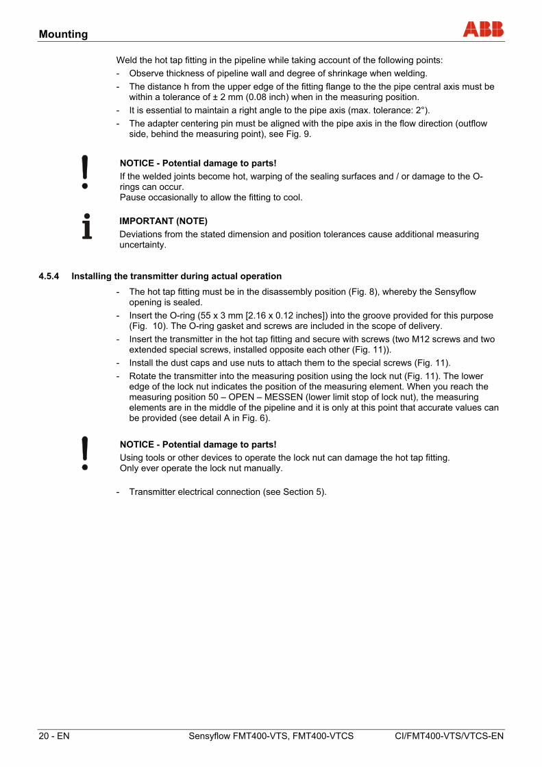
Weld the hot tap fitting in the pipeline while taking account of the following points:
- Observe thickness of pipeline wall and degree of shrinkage when welding.
- The distance h from the upper edge of the fitting flange to the the pipe central axis must be within a tolerance of ± 2 mm (0.08 inch) when in the measuring position.
- It is essential to maintain a right angle to the pipe axis (max. tolerance: 2°).
- The adapter centering pin must be aligned with the pipe axis in the flow direction (outflow side, behind the measuring point), see Fig. 9.
NOTICE - Potential damage to parts!
If the welded joints become hot, warping of the sealing surfaces and / or damage to the O-rings can occur. Pause occasionally to allow the fitting to cool.
IMPORTANT (NOTE)
Deviations from the stated dimension and position tolerances cause additional measuring uncertainty.
4.5.4 Installing the transmitter during actual operation
- The hot tap fitting must be in the disassembly position (Fig. 8), whereby the Sensyflow opening is sealed.
- Insert the O-ring (55 x 3 mm [2.16 x 0.12 inches]) into the groove provided for this purpose (Fig. 10). The O-ring gasket and screws are included in the scope of delivery.
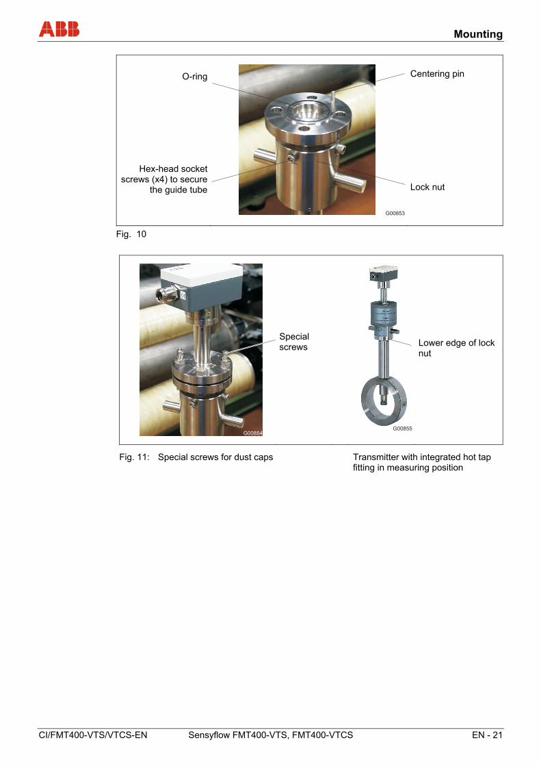
- Insert the transmitter in the hot tap fitting and secure with screws (two M12 screws and two extended special screws, installed opposite each other (Fig. 11)).
- Install the dust caps and use nuts to attach them to the special screws (Fig. 11).
- Rotate the transmitter into the measuring position using the lock nut (Fig. 11). The lower edge of the lock nut indicates the position of the measuring element. When you reach the measuring position 50 – OPEN – MESSEN (lower limit stop of lock nut), the measuring elements are in the middle of the pipeline and it is only at this point that accurate values can be provided (see detail A in Fig. 6).
NOTICE - Potential damage to parts!
Using tools or other devices to operate the lock nut can damage the hot tap fitting. Only ever operate the lock nut manually.
- Transmitter electrical connection (see Section 5).
Mounting
CI/FMT400-VTS/VTCS-EN Sensyflow FMT400-VTS, FMT400-VTCS EN - 21
O-ring
Hex-head socket screws (x4) to secure
the guide tube
G00853
Centering pin
Lock nut
Fig. 10
G00854
Special screws
G00855
Lower edge of lock nut
Fig. 11: Special screws for dust caps Transmitter with integrated hot tap fitting in measuring position
Mounting
22 - EN Sensyflow FMT400-VTS, FMT400-VTCS CI/FMT400-VTS/VTCS-EN
4.5.5 Disassembling the transmitter during actual operation
- Using the lock nut, rotate the hot tap fitting into the disassembly position. (Upper limit stop of lock nut, with lettering 0 - CLOSE - ZU must be visible; see detail A in Fig. 6).
- Electrically disconnect transmitter according to operating instructions.
- Remove the nuts for the dust caps and carefully release the transmitter mounting screws.
WARNING
If you release the transmitter mounting screws while the fitting is in the measuring position, the flowmeter sensor will fly out. This can result in severe injuries or death. Only release the screws when the fitting is in the disassembly position.
CAUTION
When you disassemble the transmitter, small quantities of process gas may escape due to the nature of the design. If you are using hazardous gases, this can result in minor injuries. Ensure adequate ventilation.
WARNING
If the fitting is in the installation position or the hot tap fitting is defective, larger quantities of hazardous gases can escape when you release the mounting screws. This can result in severe injuries or death. Abort the procedure immediately and retighten the screws. If the fitting is in the disassembly position, the transmitter can only be disassembled once the pipeline has been emptied, and where necessary, flushed out.
- Pull the transmitter out of the hot tap fitting (do not tip to the side).
Electrical connections
CI/FMT400-VTS/VTCS-EN Sensyflow FMT400-VTS, FMT400-VTCS EN - 23
5 Electrical connections
The device must have been installed before the electrical cables are connected. The supply power must be switched off.
Once the steps described below have been completed, the device is ready to be put into operation.
G00823
12
34
UIN
I OU
T2
4V
AC
/DC
0/4
...
20
mA
++
--
1
6
4 5
2
3
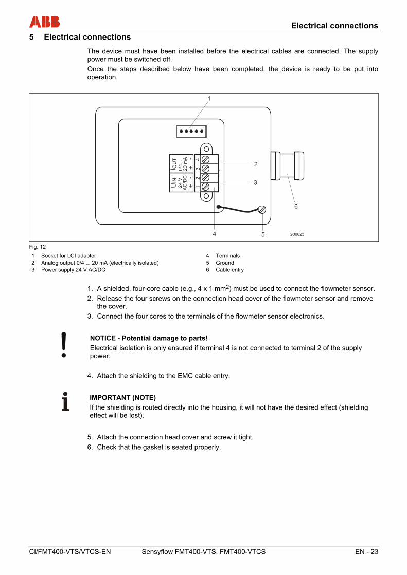
Fig. 12
1 Socket for LCI adapter 2 Analog output 0/4 ... 20 mA (electrically isolated) 3 Power supply 24 V AC/DC
4 Terminals 5 Ground 6 Cable entry
1. A shielded, four-core cable (e.g., 4 x 1 mm2) must be used to connect the flowmeter sensor.
2. Release the four screws on the connection head cover of the flowmeter sensor and remove the cover.
3. Connect the four cores to the terminals of the flowmeter sensor electronics.
NOTICE - Potential damage to parts!
Electrical isolation is only ensured if terminal 4 is not connected to terminal 2 of the supply power.
4. Attach the shielding to the EMC cable entry.
IMPORTANT (NOTE)
If the shielding is routed directly into the housing, it will not have the desired effect (shielding effect will be lost).
5. Attach the connection head cover and screw it tight.
6. Check that the gasket is seated properly.
Commissioning
24 - EN Sensyflow FMT400-VTS, FMT400-VTCS CI/FMT400-VTS/VTCS-EN
6 Commissioning
The device may only be started up / opened by qualified operating personnel. The device must be installed and the electrical signal lines must be connected prior to start-up.
6.1 Checking the installation
Prior to start-up, check that the equipment has been installed correctly:
• Is the device securely fastened?
• Have all the electrical signal, control and interface cables been laid and connected correctly?
6.2 Connecting the power supply
Step Action
1.
2.
3.
Check whether the voltage specified on the name plate matches the line voltage.
Use a supply power line with sufficient dimensions and ratings (circuit breaker).
Connect the supply line to the supply power.
WARNING
When connecting the supply power, the information provided below must be observed. Failure to observe the information provided can result in severe injuries or death.
IMPORTANT (NOTE)
In the case of 24 V UC supply power, the device may only be supplied with a safely isolated low voltage (DIN VDE 0106).
Under no circumstances must the line voltage (115 V AC or 230 V AC) be connected to the 24 V UC input. Doing so would damage the device electronics beyond repair.
6.3 Switching on
WARNING
Before switching the device on, check that all the tasks described in the previous sections have been carried out correctly. Failure to observe the information provided can result in severe injuries or death.
Check again to ensure that the set operating voltage matches the supply power voltage.
WARNING
Switching the device on while the rear housing cover is open can result in an electric shock; in potentially explosive atmospheres, there is an additional risk of explosion. This can result in severe injuries or death. Only switch on the supply power when the housing cover is closed.
Switching on the supply power
Once the supply power has been switched on, the device starts to run automatically.
Parameterization
CI/FMT400-VTS/VTCS-EN Sensyflow FMT400-VTS, FMT400-VTCS EN - 25
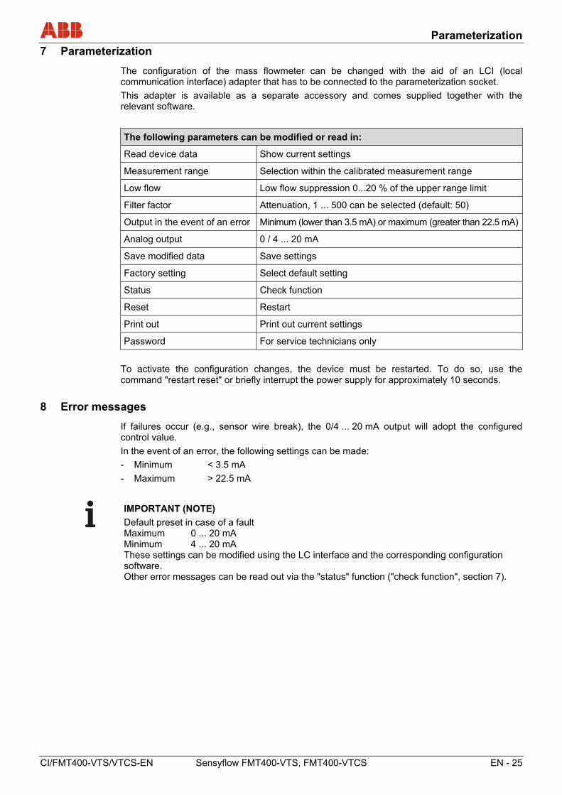
7 Parameterization
The configuration of the mass flowmeter can be changed with the aid of an LCI (local communication interface) adapter that has to be connected to the parameterization socket.
This adapter is available as a separate accessory and comes supplied together with the relevant software.
The following parameters can be modified or read in:
Read device data Show current settings
Measurement range Selection within the calibrated measurement range
Low flow Low flow suppression 0...20 % of the upper range limit
Filter factor Attenuation, 1 ... 500 can be selected (default: 50)
Output in the event of an error Minimum (lower than 3.5 mA) or maximum (greater than 22.5 mA)
Analog output 0 / 4 ... 20 mA
Save modified data Save settings
Factory setting Select default setting
Status Check function
Reset Restart
Print out Print out current settings
Password For service technicians only
To activate the configuration changes, the device must be restarted. To do so, use the command "restart reset" or briefly interrupt the power supply for approximately 10 seconds.
8 Error messages
If failures occur (e.g., sensor wire break), the 0/4 ... 20 mA output will adopt the configured control value.
In the event of an error, the following settings can be made:
- Minimum < 3.5 mA
- Maximum > 22.5 mA
IMPORTANT (NOTE)
Default preset in case of a fault Maximum 0 ... 20 mA Minimum 4 ... 20 mA These settings can be modified using the LC interface and the corresponding configuration software. Other error messages can be read out via the "status" function ("check function", section 7).
Appendix
26 - EN Sensyflow FMT400-VTS, FMT400-VTCS CI/FMT400-VTS/VTCS-EN
9 Appendix
9.1 Decommissioning and packaging
Packaging the device ready for transport or return to the manufacturer
If the original packaging material is no longer available, wrap the device in bubble wrap or corrugated cardboard and place it in a box of sufficient size lined with a shock-absorbing material (e.g., foam rubber). The thickness of the padding should be appropriate for the device weight and type of shipment. The box must be handled with care and labeled accordingly.
For overseas shipment, always add a desiccant (e.g., silica gel) and hermetically seal the device plus desiccant in a layer of polythene that is 0.2 mm thick. Use an amount of desiccant that is appropriate for the packing volume and the expected transport time (at least sufficient for 3 months). You should also line the box with a layer of union paper.
All devices returned to the manufacturer must be accompanied by a completed and signed decontamination certificate (see Appendix). Without this, ABB will not be able to process the return.
9.2 Approvals and certifications
CE mark
The version of the device as provided by us meets the requirements of the following European directives:
- EMC Directive 2014/30/EU
- ATEX Directive 2014/34/EU
Explosion protection
Designation relating to intended use in potentially explosive atmospheres in compliance with:
- ATEX Directive
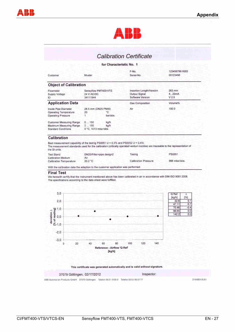
Calibration
DAkkS- / ILAC-accredited calibration equipment D-K-15081-01-00
- Example certificate
IMPORTANT (NOTE)
All documentation, declarations of conformity and certificates are available in ABB's download area.
www.abb.com/flow
Appendix
CI/FMT400-VTS/VTCS-EN Sensyflow FMT400-VTS, FMT400-VTCS EN - 27


A
ABB has Sales & Customer Support expertise in over 100 countries worldwide.
www.abb.com/flow
The Company’s policy is one of continuous product improvement and the right is reserved to modify the information contained herein without notice.
Printed in the Fed. Rep. of Germany (07.2017)
© ABB 2017
C
I/FM
T40
0-V
TS
/VT
CS
-EN
Rev
. B
3KXF421002R4401
ABB Limited
Measurement & Analytics
Howard Road, St. Neots
Cambridgeshire, PE19 8EU
UK
Tel: +44 (0) 870 600 6122
Fax: +44 (0)1480 213 339
Mail: [email protected]
ABB Inc.
Measurement & Analytics
125 E. County Line Road
Warminster, PA 18974
USA
Tel: +1 215 674 6000
Fax: +1 215 674 7183
ABB Automation Products GmbH
Measurement & Analytics
Dransfelder Str. 2
37079 Goettingen
Germany
Tel: +49 551 905-0
Fax: +49 551 905-777
Mail: [email protected]