ciatcooler lp / ilp - ciat.uk.com · water chillers and air-water heat pumps 6 heat pumps - air...
TRANSCRIPT

NA 12.122 H 06 - 2016
BROCHURE
InstallationOperation
CommissioningMaintenance
CIA
TC
oole
r LP
/ IL
P


HEAT PUMPS - AIR CONDITIONING - REFRIGERATION - AIR HANDLING - HEAT EXCHANGE - NA 12.122 H
Water chillers and air-water heat pumps
3
CIA
TCoo
ler L
P
Contents1. Introduction .......................................................................................................................................................................................................5
2. Operation limits .................................................................................................................................................................................................5
3. Available confi gurations ....................................................................................................................................................................................6
4. Technical characteristics ...................................................................................................................................................................................7
5. Unit identifi cation .............................................................................................................................................................................................13
6. Safety advice ...................................................................................................................................................................................................13
7. Transport .........................................................................................................................................................................................................14
Placement on site ............................................................................................................................................................................................14
Centre of gravity coordinates ..........................................................................................................................................................................15
8. Location and assembling ................................................................................................................................................................................16
Location designation .......................................................................................................................................................................................16
Minimum free space for commissioning and maintenance operations ...........................................................................................................16
Anchorage for antivibrators .............................................................................................................................................................................17
Sound levels ....................................................................................................................................................................................................21
9. Checking before commissioning .....................................................................................................................................................................23
Electrical connections .....................................................................................................................................................................................23
Condensate drain connection .........................................................................................................................................................................24
Checks in the centrifugal fans: STD version ...................................................................................................................................................25
Air ducts connections ......................................................................................................................................................................................26
Hydraulic connections .....................................................................................................................................................................................27
10. Safety elements ..............................................................................................................................................................................................34
Location of the control and safety elements ....................................................................................................................................................35
11. Options ............................................................................................................................................................................................................36
Condensation pressure control .......................................................................................................................................................................36
Air fi lter ............................................................................................................................................................................................................36
Separate hydraulic module .............................................................................................................................................................................37
Coil protection grille .........................................................................................................................................................................................37
Cooling recovery circuit ...................................................................................................................................................................................38
12. Commissioning ................................................................................................................................................................................................41
Checks prior to commissioning .......................................................................................................................................................................41
Possible problems at commissioning ..............................................................................................................................................................43
Operational checks .........................................................................................................................................................................................43
13. Maintenance ....................................................................................................................................................................................................44
14. Control and analysis of breakdowns................................................................................................................................................................48
Annex I: Quick overview of the installation ............................................................................................................................................................49


HEAT PUMPS - AIR CONDITIONING - REFRIGERATION - AIR HANDLING - HEAT EXCHANGE - NA 12.122 H
Water chillers and air-water heat pumps
5
CIA
TCoo
ler L
P
1. INTRODUCTION
2. OPERATION LIMITS
Series CIATCooler LPAir-condensed water chillers.
Series CIATCooler ILPReversible heat pump units for operation in negative outdoor temperatures (greater than -15ºC WB) for water heating and chilling. Defrosting by reversing the cycle.
After manufacturing, all units are charged with refrigerant and are tested at the factory, verifying the correct operation of all their components within the operating range for which they are intended.
The units comply with European Directives: Machinery 2006/42/EC - EMC 2014/30/EU - LVD 2014/35/EU - PED 2014/68/EC (Category 2) - RoHS 2011/65/EU - Eco-design 2009/125/CE - Eco-labelling 2010/30/EU; and with Harmonised Standard: EN 378-2:2012.
Those in charge of the installation, commissioning, operation and maintenance of the unit must know the instructions contained in this brochure and the specifi c technical characteristics of the installation place.
Cooling capacity:
Heating capacity:
17,7 to 193,5 kW21,8 to 214,0 kW
The CIATCooler LP / ILP cooling units and reversible heating pumps are compact outdoor air/water units.
Available in two versions:
• STD (Standard)• HEE (High Energy Effi ciency) These units have been made for operation indoors in the production of hot and/or cold water, applicable to heating, cooling, and industry.
They are equipped with centrifugal fans (STD version) or electronic plug-fans (HEE version), plate exchangers, hermetic scroll compressors, and electronic control with microprocessors, components optimised for the R-410A refrigerant.
This range is also offered with an integrated circulation pump: LPC / ILPC and optionally, with a hydraulic module (attached to the unit or separate) equipped with a buffer tank.
The entire range also has the option to include a desuperheater circuit that allows for the production of hot water at a temperature greater than in the condensation circuits.
With control of the condensation pressure operating up to -15ºC.
Minimum outlet temperature. With the option of glycol water for lower temperature operation from 5ºC to -7ºC.
Series
Cooling mode Heating modeAir Water
(outlet T.)Air Water
(outlet T.)
Max. Min. Max. Min. Max. Min. Max. Min.
LP 46ºC 12ºC 18ºC 5ºC -- -- -- --
ILP 46ºC 12ºC 18ºC 5ºC 20ºC DB -15ºC DB 55ºC 30ºC
+55+50+45+30
+20
+10
+0
-10
-15
Out
door
tem
pera
ture
°C
DB
Outlet water temperature in the condenser °C+18+50-7
-15
+46
Out
door
tem
pera
ture
°C
DB
Mandatory glycol
Outlet water temperature in the evaporator °C
Cond
ensa
tion
pres
sure
contr
ol

Water chillers and air-water heat pumps
HEAT PUMPS - AIR CONDITIONING - REFRIGERATION - AIR HANDLING - HEAT EXCHANGE - NA 12.122 H6
CIATCooler LP3. AVAILABLE CONFIGURATIONS
According to the air discharge:
• Assembly M00
HORIZONTAL air discharge: models 90 to 600 (STD version) and models 90 to 360 (HEE version).
• Assembly M01
VERTICAL air discharge: all models.
According to the type of outlet fan:
• STD version (Standard):
Centrifugal fan coupling by pulleys and belts.
• HEE version (High Energy Effi ciency):
Variable speed electronic plug-fan.
M00
M01
According to the components of the hydraulic circuit:
• LP / ILP version
The unit incorporates only the plate exchanger.
• LPC / ILPC version with hiydraulic module
The unit incorporates, besides the motorpump group, a module with a thermal buffer tank.
The module can be supplied:
- Coupled to the LPC / ILPC unit, models 90 to 360.
- Separate for connection on site by the installer. In this case, the minimum distance between the unit and the module is 167 mm.
• LPC / ILPC version
In addition to the plate exchanger, the unit includes a motorpump group.
STD
HEE
Moduleseparate
Modulecoupled
Models STD version(Standard)
HEE version (High Energy Effi ciency)
1 circuit1 compressor 90 / 100 / 120 / 160 / 180 90 / 100 / 120 / 160 / 180
1 circuit2 compressors
200 / 240 / 280 / 320 / 360 420 / 480 / 600
200 / 240 / 280 / 320 / 360420 / 480 / 600
2 circuits4 compressors 640 / 720 / 840 / 960 640 / 720

HEAT PUMPS - AIR CONDITIONING - REFRIGERATION - AIR HANDLING - HEAT EXCHANGE - NA 12.122 H
Water chillers and air-water heat pumps
7
CIA
TCoo
ler L
P
4. TECHNICAL CHARACTERISTICSSTD version
CIATCooler LP / ILP 90V-STD
100V-STD
120V-STD
160V-STD
180V-STD
200V-STD
240V-STD
280V-STD
320V-STD
360V-STD
Cooling capacities
Net cooling capacity (kW) 17,70 21,10 25,20 32,70 36,00 43,70 49,30 55,80 68,10 74,30
Net power input (kW) 7,75 9,15 10,00 12,60 14,40 18,80 19,70 22,40 24,90 28,70
Net effi ciency EER 2,29 2,31 2,51 2,60 2,49 2,32 2,51 2,49 2,73 2,59
Seasonal effi ciency ESEER 2,61 2,59 2,81 2,94 2,85 2,71 2,97 2,98 3,29 3,14
Heating capacities
Net heating capacity (kW) 21,80 26,10 29,70 38,30 42,60 51,60 58,50 66,90 76,60 84,80
Net power input (kW) 7,31 8,90 9,90 12,90 14,20 18,40 19,60 22,40 24,80 28,20
Net effi ciency COP 2,97 2,94 3,00 2,97 3,01 2,80 2,99 2,98 3,08 3,01
Seasonal effi ciency Average climate
SCOP 3,11 3,12 3,07 2,95 2,95 3,07 3,07 2,95 2,95 3,17
ŋs Heat 121% 122% 120% 115% 115% 120% 120% 115% 115% 124%
Prated (kW) 16,77 19,19 21,82 26,33 31,31 38,59 41,71 44,94 51,08 65,47
Seasonal effi ciency Warmer climate
SCOP 3,59 3,63 3,57 3,42 3,35 3,42 3,71 3,66 3,61 3,71
ŋs Heat 140% 142% 140% 134% 131% 134% 145% 143% 141% 145%
Prated (kW) 12,73 14,70 16,72 24,30 27,32 34,90 39,44 42,83 47,04 58,00
Outdoorcircuit centrifugal fan
Nominal air fl ow (m3/h) 6500 7000 10000 12200 12200 16000 20000 24400 24400 24400
Available static pressure (mm.w.c.) 20
Number / turbines 1 2
Motor output (kW) 2,2 2,2 3,0 4,0 4,0 2 x 3,0 2 x 3,0 2 x 4,0 2 x 4,0 2 x 4,0
Power input (kW) 1,46 1,77 2,33 2,83 2,83 4,68 4,66 5,3 5,66 5,66
Speed (r.p.m.) 973 1027 837 734 734 1082 837 705 734 734
Indoor circuit
Nominal water fl ow (m3/h) 3,1 3,7 4,3 5,7 6,2 7,5 8,5 9,6 11,7 12,8
Pressure drop (m.w.c.) 2,3 3,2 2,9 4,7 2,9 4,2 3,2 4,0 2,1 2,6
Minimum water fl ow (m3/h) 2,2 2,7 3,1 4,1 4,3 4,7 6,2 7,2 8,3 8,6
Maximum water fl ow (m3/h) 6,2 7,4 8,8 11,3 12,7 15,0 17,2 19,2 23,6 26,0
Type of hydraulic connections Gas threaded
Diameter of connections 1 1/4" M 1 1/2" M 2" M
Compressor
Type Scroll
No. of compressors / stages / circuits 1 / 1 / 1 2 / 2 / 1
Oil type Copeland 3MAF 32 cST, Danfoss POE 160 SZ, ICI Emkarate RL 32 CF, Mobil EAL Artic 22 CC
Volume of oil (l) 3,0 3,3 3,3 3,3 6,2 2 x 3,3 2 x 3,3 2 x 3,3 2 x 3,3 2 x 6,2
Refrigerant
Type R-410A
Global warming potential (GWP) 2.088
Charge (kg) 5,9 6,1 6,6 6,9 7,6 9,2 12,3 12,4 14,9 15,4
Environment impact (tCO2 e) 12,3 12,7 13,8 14,4 15,9 19,2 25,7 25,9 31,1 32,2
Electrical characteristics
Electrical power supply 400 V / III ph / 50 Hz (±10%)
Power supply 3 Wires + Ground + Neutral
Maximum absorbed current
Compressor (A) 15,2 17,3 20,5 25,4 30,5 34,6 41,0 45,9 50,8 61,0
Fan (A) 5,0 5,0 6,9 8,9 8,9 13,8 13,8 17,8 17,8 17,8
Control (A) 0,9 0,9 0,9 0,9 0,9 1,8 1,8 1,8 1,8 1,8
Total (A) 21,1 23,2 28,3 35,2 40,3 50,2 56,6 65,5 70,4 80,6
Dimensions
Length (mm) 1117 1398 2113 2673
Width (mm) 860 860 860 860
Height (mm) 1447 1727 1447 1727
WeightEmpty (kg) 302 310 372 390 388 564 644 676 710 716
In operation (kg) 306 315 379 397 396 579 659 692 728 733
Cooling capacity calculated in accordance with the EN-14511-2013 standard given for outlet water temperature conditions of 7ºC and 35ºC outdoor temperature. Heating capacity calculated in accordance with the EN-14511-2013 standard given for outlet water temperature conditions of 45ºC and 6ºC WB outdoor temperature. Total power input by compressor, motorised fan and electronic control under nominal conditions, calculated in accordance with the EN-14511-2013 standard. Options are not included. European Seasonal Energy Effi ciency Ratio (ESEER) obtained in accordance with the calculation conditions established by the certifi cation body EUROVENT.Values calculated in accordance with the EN-14825-2013 standard given for bivalente temperature of -5ºC in average climate and 2ºC in warmer climate.Energy-effi cient motors IE2.Climatic warming potential of a kilogram of fl uorinated greenhouse gas in relation to a kilogram of carbon dioxide over a period of 100 years.With the transport brackets the machine is 106 mm higher.

Water chillers and air-water heat pumps
HEAT PUMPS - AIR CONDITIONING - REFRIGERATION - AIR HANDLING - HEAT EXCHANGE - NA 12.122 H8
CIATCooler LP4. TECHNICAL CHARACTERISTICS
STD version
CIATCooler LP / ILP 420V-STD
480V-STD
600V-STD
640V-STD
720V-STD
840V-STD
960V-STD
Cooling capacities
Net cooling capacity (kW) 88,80 97,00 119,00 134,60 152,30 177,30 193,50
Net power input (kW) 33,20 37,40 48,10 50,50 60,10 66,80 76,20
Net effi ciency EER 2,68 2,59 2,48 2,66 2,53 2,65 2,54
Seasonal effi ciency ESEER 3,25 3,20 3,12 3,15 3,05 3,12 3,01
Heating capacities
Net heating capacity (kW) 98,70 108,70 132,30 143,40 163,50 196,10 214,10
Net power input (kW) 34,40 38,40 48,80 50,20 57,40 67,20 74,80
Net effi ciency COP 2,87 2,83 2,71 2,86 2,85 2,92 2,86
Seasonal effi ciency Average climate
SCOP 3,12 3,25 3,29 3,10 3,21 3,14 3,36
ŋs Heat 122% 127% 128% 121% 125% 123% 131%
Prated (kW) 82,03 90,05 110,77 117,76 135,09 159,65 174,08
Seasonal effi ciency Warmer climate
SCOP 3,54 3,70 3,73 3,46 3,62 3,64 3,81
ŋs Heat 138% 145% 146% 135% 142% 142% 149%
Prated (kW) 70,04 76,82 94,07 100,70 114,85 135,74 147,87
Outdoorcircuit centrifugal fan
Nominal air fl ow (m3/h) 30000 30000 37500 48000 48000 60000 60000
Available static pressure (mm.w.c.) 20
Number / turbines 2 3 4
Motor output (kW) 2 x 5,5 2 x 5,5 3 x 4,0 4 x 4,0 4 x 4,0 4 x 5,5 4 x 5,5
Power input (kW) 7,72 7,72 9,12 14,64 14,64 16,52 16,52
Speed (r.p.m.) 737 737 751 940 940 771 771
Indoor circuit
Nominal water fl ow (m3/h) 15,4 16,8 20,6 23,3 26,3 30,6 33,5
Pressure drop (m.w.c.) 4,1 4,9 5,6 3,9 5,1 5,2 6,1
Minimum water fl ow (m3/h) 12,2 13,4 16,9 18,2 20,9 24,1 26,6
Maximum water fl ow (m3/h) 31,4 34,5 42,1 48,2 54,3 63,5 69,4
Type of hydraulic connections Gas threaded
Diameter of connections 2 1/2” H
Compressor
Type Scroll
No. of compressors / stages / circuits 2 / 2 / 1 4 / 4 / 2
Oil type Copeland 3MAF 32 cST, Danfoss POE 160 SZ, ICI Emkarate RL 32 CF, Mobil EAL Artic 22 CC
Volume of oil (l) 4,7 + 3,3 2 x 4,7 2 x 6,8 4 x 3,3 4 x 3,3 2 x (4,7 + 3,3) 4 x 4,7
Refrigerant
Type R-410A
Global warming potential (GWP) 2.088
Charge (kg) 24,0 25,0 26,0 37,0 38,0 49,0 50,0
Environment impact (tCO2 e) 50,1 52,2 54,3 77,3 79,3 102,3 104,4
Electrical characteristics
Electrical power supply 400 V / III ph / 50 Hz (±10%)
Power supply 3 Wires + Ground + Neutral
Maximum absorbed current
Compressor (A) 67,0 73,0 89,2 101,6 122,0 134,0 146,0
Fan (A) 23,2 23,2 26,7 35,6 35,6 46,4 46,4
Control (A) 1,8 1,8 1,8 1,8 1,8 1,8 1,8
Total (A) 92,0 98,0 117,7 139,0 159,4 182,2 194,2
Dimensions
Length (mm) 3400 3600 4500
Width (mm) 900 1150 1200
Height (mm) 1970 1970 1970
WeightEmpty (kg) 1046 1122 1211 1461 1472 1949 2101
In operation (kg) 1065 1142 1232 1493 1504 1986 2138
Cooling capacity calculated in accordance with the EN-14511-2013 standard given for outlet water temperature conditions of 7ºC and 35ºC outdoor temperature. Heating capacity calculated in accordance with the EN-14511-2013 standard given for outlet water temperature conditions of 45ºC and 6ºC WB outdoor temperature. Total power input by compressor, motorised fan and electronic control under nominal conditions, calculated in accordance with the EN-14511-2013 standard. Options are not included. European Seasonal Energy Effi ciency Ratio (ESEER) obtained in accordance with the calculation conditions established by the certifi cation body EUROVENT.Values calculated in accordance with the EN-14825-2013 standard given for bivalente temperature of -5ºC in average climate and 2ºC in warmer climate.Energy-effi cient motors IE2.Climatic warming potential of a kilogram of fl uorinated greenhouse gas in relation to a kilogram of carbon dioxide over a period of 100 years.With the transport skids the machine is 120 mm higher.

HEAT PUMPS - AIR CONDITIONING - REFRIGERATION - AIR HANDLING - HEAT EXCHANGE - NA 12.122 H
Water chillers and air-water heat pumps
9
CIA
TCoo
ler L
P
4. TECHNICAL CHARACTERISTICSSTD version with pump included
European Seasonal Energy Effi ciency Ratio (ESEER) obtained in accordance with the calculation conditions established by the certifi cation body EUROVENT.Values calculated in accordance with the EN-14825-2013 standard given for bivalente temperature of -5ºC in average climate and 2ºC in warmer climate. The water capacity for the installation indicated in this table corresponds to the maximum that the installation allows based on the expansion vessel assembled on the unit.
The volume of the buffer tank has been taken into account for this section. In case the capacity of the installation is greater, it is necessary to add a supplementary expansion vessel to the installation based on its volume.
This temperature corresponds to the temperature that the circuit may reach when the unit is stopped. This case must be considered for cooling-only units. This temperature corresponds to the maximum temperature that the circuit may reach when operating in a heat pump.Minimum distance between the unit and the separte hydraulic module: 167 mm.
CIATCooler LPC / ILPC 90V-STD
100V-STD
120V-STD
160V-STD
180V-STD
200V-STD
240V-STD
280V-STD
320V-STD
360V-STD
Cooling Seasonal effi ciency ESEER 2,67 2,61 2,89 2,97 2,84 2,73 2,99 2,99 3,29 3,17
Heating
Seasonal effi ciency Average climate
SCOP 3,24 3,13 3,10 2,95 3,06 2,96 3,10 2,95 2,96 3,02ŋs Heat 126% 122% 121% 115% 119% 115% 121% 115% 115% 118%Prated (kW) 16,83 19,20 21,83 26,21 30,53 38,31 41,45 44,73 51,02 65,65
Seasonal effi ciency Warmer climate
SCOP 3,82 3,60 3,60 3,44 3,57 3,35 3,74 3,56 3,55 3,40ŋs Heat 150% 141% 141% 135% 140% 131% 147% 139% 139% 133%Prated (kW) 12,77 14,71 16,72 24,22 27,28 34,73 39,27 42,59 46,95 58,15
Indoor circuit
Nominal water fl ow (m3/h) 3,1 3,7 4,3 5,7 6,2 7,5 8,5 9,6 11,7 12,8Pressure drop (m.w.c.) 3,1 4,2 3,8 6,2 4,5 4,9 4,1 5,1 3,5 4,3
Expansion vessel
Volume (l) 12 20Filled pressure (kg/cm2) 1,5
Buffer tank(LPC / ILPC + module)
Volume of the buffer tank (l) 100 150 225Maximum water capacity of the installation
Water 40ºC (l) 700 650 1100 Water 50ºC (l) 410 360 625
Drained diameter 3/4” M 1” M
Anti-freeze elec. heater (standard)
Voltage 230 V / I phOutput (kW) 1 kW (4,3 A)
Dimensions
Length (mm)
LPC / ILPC 1117 1398 2113 2673Module 1000 1000 1000 1000
Width (mm) 860 860 860 860Height (mm) 1447 1727 1447 1727
WeightLPC / ILPC
Empty (kg) 318 328 390 408 408 586 666 700 736 741In operation (kg) 335 345 410 428 429 622 702 736 774 780
Hydraulic module
Empty (kg) 139 139 161 161 161 161 169 169 169 169In operation (kg) 242 242 315 315 315 393 404 404 404 404
CIATCooler LPC / ILPC 420V-STD
480V-STD
600V-STD
640V-STD
720V-STD
840V-STD
960V-STD
Cooling Seasonal effi ciency ESEER 3,13 3,07 3,02 3,00 2,87 3,04 2,89
Heating
Seasonal effi ciency Average climate
SCOP 2,95 3,04 3,09 2,95 2,95 3,10 3,21ŋs Heat 115% 119% 120% 115% 115% 121% 126%Prated (kW) 82,76 90,84 111,30 118,94 137,14 159,98 175,15
Seasonal effi ciency Warmer climate
SCOP 3,29 3,61 3,34 3,42 3,34 3,46 3,68ŋs Heat 129% 141% 131% 134% 131% 135% 144%Prated (kW) 70,59 77,41 95,09 102,06 116,45 137,01 148,68
Indoor circuit
Nominal water fl ow (m3/h) 15,3 16,7 20,5 23,2 26,2 30,5 33,1Pressure drop (m.w.c.) 7,5 8,8 11,1 10,8 13,3 12,9 15,1
Expansion vessel
Volume (l) 35 50Filled pressure (kg/cm2) 1,5
Buffer tank(LPC / ILPC + module)
Volume of the buffer tank (l) 275 275 375Maximum water capacity of the installation
Water 40ºC (l) 2050 3035 2985 Water 50ºC (l) 1210 1840 1790
Drained diameter 1” M
Anti-freeze elec. heater (standard)
Voltage 230 V / I phOutput (kW) 1 kW (4,3 A)
Dimensions
Length (mm)
LPC / ILPC 3400 3600 4500Module 1000 1000 1000
Width (mm) 900 1150 1200Height (mm) 1970 1970 1970
WeightLPC / ILPC
Empty (kg) 1107 1183 1272 1512 1523 2038 2189In operation (kg) 1169 1246 1336 1592 1603 2131 2282
Hydraulic module
Empty (kg) 202 202 202 241 241 263 263In operation (kg) 486 486 486 544 544 668 668

Water chillers and air-water heat pumps
HEAT PUMPS - AIR CONDITIONING - REFRIGERATION - AIR HANDLING - HEAT EXCHANGE - NA 12.122 H10
CIATCooler LP4. TECHNICAL CHARACTERISTICS
HEE version
CIATCooler LP / ILP 90V-HEE
100V-HEE
120V-HEE
160V-HEE
180V-HEE
200V-HEE
240V-HEE
280V-HEE
Cooling capacities
Net cooling capacity (kW) 18,40 21,00 25,50 31,40 35,70 42,30 52,30 58,10
Net power input (kW) 7,20 7,95 9,10 11,50 13,60 15,50 18,20 21,20
Net effi ciency EER 2,55 2,64 2,81 2,74 2,62 2,73 2,87 2,74
Seasonal effi ciency ESEER 2,89 2,99 3,20 3,14 3,03 3,38 3,44 3,16
Heating capacities
Net heating capacity (kW) 21,40 23,90 29,30 36,40 42,50 48,60 56,60 65,00
Net power input (kW) 7,10 7,90 9,50 11,90 13,90 15,80 18,80 21,60
Net effi ciency COP 3,03 3,03 3,08 3,05 3,05 3,08 3,01 3,01
Seasonal effi ciency Average climate
SCOP 2,98 2,95 3,29 3,18 3,09 3,31 3,20 2,95
ŋs Heat 116% 115% 129% 124% 121% 129% 125% 115%
Prated (kW) 15,92 17,74 21,94 26,77 30,87 34,82 45,34 50,85
Seasonal effi ciency Warmer climate
SCOP 3,41 3,58 3,82 3,67 3,65 3,78 3,70 3,37
ŋs Heat 134% 140% 150% 144% 143% 148% 145% 132%
Prated (kW) 13,09 14,68 18,01 22,41 25,89 29,78 34,74 38,86
Outdoorcircuit plug-fan
Nominal air fl ow (m3/h) 6500 7000 10000 12200 14000 16000 20000 24400
Nominal avail. static pressure (mm.w.c.) 20
Maximum avail. static pressure (mm.w.c.) 63,7 70,3 45,6 65,1 62,7 61,0 45,6 57,3
Number / diameter 1 / 500 1 / 560 2 / 560
Motor output (kW) 2,7 2,8 3,0 2 x 3,0 2 x 4,7
Power input (kW) 1,33 1,21 1,87 2,20 2,52 2,70 3,88 5,28
Speed (r.p.m.) 1700 1780 1500 1500 1750
Indoor circuit
Nominal water fl ow (m3/h) 3,2 3,7 4,5 5,4 6,2 7,4 9,3 10,2
Pressure drop (m.w.c.) 1,6 2,1 1,6 2,4 3,1 2,5 1,4 1,6
Minimum water fl ow (m3/h) 2,8 2,9 3,8 4,1 4,6 5,7 6,7 7,5
Maximum water fl ow (m3/h) 6,6 7,4 9,1 11,3 12,8 15,0 18,4 20,7
Type of hydraulic connections Gas threaded
Diameter of connections 1 1/4” M 1 1/2” M 2” M
Compressor
Type Scroll
No. of compressors / stages / circuits 1 / 1 / 1 2 / 2 / 1
Oil type Copeland 3MAF 32 cST, Danfoss POE 160 SZ, ICI Emkarate RL 32 CF, Mobil EAL Artic 22 CC
Volume of oil (l) 3,0 3,3 3,3 3,3 6,2 2 x 3,3 2 x 3,3 2 x 3,3
Refrigerant
Type R-410A
Global warming potential (GWP) 2.088
Charge (kg) 6,0 6,3 6,8 8,9 9,2 12,4 14,4 14,8
Environment impact (tCO2 e) 12,5 13,2 14,2 18,6 19,2 25,9 30,1 30,9
Electrical characteristics
Electrical power supply 400 V / III ph / 50 Hz (±10%)
Power supply 3 Wires + Ground + Neutral
Maximum absorbed current
Compressor (A) 15,2 17,3 20,5 25,4 30,5 34,6 41,0 45,9
Fan (A) 4,2 4,3 4,6 9,2 9,2 9,2 9,2 14,6
Control (A) 0,9 0,9 0,9 0,9 0,9 1,8 1,8 1,8
Total (A) 20,3 22,5 26,0 35,5 40,6 45,6 52,0 62,3
Dimensions
Length (mm) 1117 1398 2113 2673
Width (mm) 860 860 860 860
Height (mm) 1447 1727 1447 1727
WeightEmpty (kg) 294 351 368 450 455 633 656 662
In operation (kg) 298 358 376 465 468 648 674 680
Cooling capacity calculated in accordance with the EN-14511-2013 standard given for outlet water temperature conditions of 7ºC and 35ºC outdoor temperature. Heating capacity calculated in accordance with the EN-14511-2013 standard given for outlet water temperature conditions of 45ºC and 6ºC WB outdoor temperature. Total power input by compressor, motorised fan and electronic control under nominal conditions, calculated in accordance with the EN-14511-2013 standard. Options are not included. European Seasonal Energy Effi ciency Ratio (ESEER) obtained in accordance with the calculation conditions established by the certifi cation body EUROVENT.Values calculated in accordance with the EN-14825-2013 standard given for bivalente temperature of -5ºC in average climate and 2ºC in warmer climate.Motors that are more energy effi cient than what is established by the ErP 2015 standard.Climatic warming potential of a kilogram of fl uorinated greenhouse gas in relation to a kilogram of carbon dioxide over a period of 100 years.With the transport brackets the machine is 106 mm higher.

HEAT PUMPS - AIR CONDITIONING - REFRIGERATION - AIR HANDLING - HEAT EXCHANGE - NA 12.122 H
Water chillers and air-water heat pumps
11
CIA
TCoo
ler L
P
4. TECHNICAL CHARACTERISTICSHEE version
CIATCooler LP / ILP 320V-HEE
360V-HEE
420V-HEE
480V-HEE
600V-HEE
640V-HEE
720V-HEE
Cooling capacities
Net cooling capacity (kW) 67,50 76,80 89,90 99,20 122,70 134,50 154,10
Net power input (kW) 24,10 28,20 31,90 36,40 46,10 48,50 56,70
Net effi ciency EER 2,81 2,72 2,82 2,73 2,66 2,77 2,72
Seasonal effi ciency ESEER 3,41 3,38 3,55 3,48 3,37 3,37 3,34
Heating capacities
Net heating capacity (kW) 75,40 86,30 99,60 109,30 133,60 150,80 172,00
Net power input (kW) 24,50 28,50 32,10 36,00 44,80 48,50 55,70
Net effi ciency COP 3,08 3,03 3,11 3,03 2,98 3,11 3,09
Seasonal effi ciency Average climate
SCOP 3,31 3,10 3,23 3,17 3,13 3,18 3,30
ŋs Heat 129% 121% 126% 124% 122% 124% 129%
Prated (kW) 61,19 62,56 71,89 91,68 96,42 108,74 124,22
Seasonal effi ciency Warmer climate
SCOP 3,77 3,65 3,83 3,79 3,69 3,67 3,79
ŋs Heat 148% 143% 150% 149% 145% 144% 149%
Prated (kW) 46,83 51,58 59,40 71,82 78,98 89,89 102,42
Outdoorcircuit plug-fan
Nominal air fl ow (m3/h) 24400 24400 30000 30000 34000 48000 48000
Nominal avail. static pressure (mm.w.c.) 20
Maximum avail. static pressure (mm.w.c.) 66,9 66,9 60,9 60,6 64,4 62,9 62,9
Number / diameter 2 / 560 3 / 560 4 / 560
Motor output (kW) 2 x 4,7 3 x 3,0 3 x 4,7 4 x 4,7
Power input (kW) 4,78 4,78 5,37 5,37 6,72 10,08 10,08
Speed (r.p.m.) 1750 1500 1750 1750
Indoor circuit
Nominal water fl ow (m3/h) 11,7 13,3 15,6 17,2 21,0 23,2 26,5
Pressure drop (m.w.c.) 2,7 3,4 4,2 4,9 5,9 3,0 3,9
Minimum water fl ow (m3/h) 9,1 10,7 12,2 13,5 17,4 18,1 21,2
Maximum water fl ow (m3/h) 23,6 26,8 31,7 34,9 42,8 47,5 54,3
Type of hydraulic connections Gas threaded
Diameter of connections 2 1/2” F
Compressor
Type Scroll
No. of compressors / stages / circuits 2 / 2 / 1 4 / 4 / 2
Oil type Copeland 3MAF 32 cST, Danfoss POE 160 SZ, ICI Emkarate RL 32 CF, Mobil EAL Artic 22 CC
Volume of oil (l) 2 x 3,3 2 x 3,3 4,7 + 3,3 2 x 4,7 2 x 6,8 4 x 3,3 4 x 3,3
Refrigerant
Type R-410A
Global warming potential (GWP) 2.088
Charge (kg) 24,0 24,0 36,0 36,0 37,0 48,0 49,0
Environment impact (tCO2 e) 50,1 50,1 75,2 75,2 77,3 100,2 102,3
Electrical characteristics
Electrical power supply 400 V / III ph / 50 Hz (±10%)
Power supply 3 Wires + Ground + Neutral
Maximum absorbed current
Compressor (A) 50,8 61,0 67,0 73,0 89,2 101,6 122,0
Fan (A) 14,6 14,6 13,8 13,8 21,9 29,2 29,2
Control (A) 1,8 1,8 1,8 1,8 1,8 1,8 1,8
Total (A) 67,2 77,4 82,6 88,6 112,9 132,6 153,0
Dimensions
Length (mm) 3400 3600 4500
Width (mm) 900 1150 1200
Height (mm) 1970 1970 1970
WeightEmpty (kg) 942 948 1263 1339 1420 1713 1724
In operation (kg) 961 966 1285 1361 1444 1749 1761
Cooling capacity calculated in accordance with the EN-14511-2013 standard given for outlet water temperature conditions of 7ºC and 35ºC outdoor temperature. Heating capacity calculated in accordance with the EN-14511-2013 standard given for outlet water temperature conditions of 45ºC and 6ºC WB outdoor temperature. Total power input by compressor, motorised fan and electronic control under nominal conditions, calculated in accordance with the EN-14511-2013 standard. Options are not included. European Seasonal Energy Effi ciency Ratio (ESEER) obtained in accordance with the calculation conditions established by the certifi cation body EUROVENT.Values calculated in accordance with the EN-14825-2013 standard given for bivalente temperature of -5ºC in average climate and 2ºC in warmer climate.Motors that are more energy effi cient than what is established by the ErP 2015 standard.Climatic warming potential of a kilogram of fl uorinated greenhouse gas in relation to a kilogram of carbon dioxide over a period of 100 years.With the transpor skids the machine is 120 mm higher.

Water chillers and air-water heat pumps
HEAT PUMPS - AIR CONDITIONING - REFRIGERATION - AIR HANDLING - HEAT EXCHANGE - NA 12.122 H12
CIATCooler LP4. TECHNICAL CHARACTERISTICS
HEE version with pump included
CIATCooler LPC / ILPC 90V-HEE
100V-HEE
120V-HEE
160V-HEE
180V-HEE
200V-HEE
240V-HEE
280V-HEE
Cooling Seasonal effi ciency ESEER 2,95 3,00 3,22 3,17 3,02 3,39 3,44 3,15
Heating
Seasonal effi ciency Average climate
SCOP 3,12 2,95 3,33 3,20 3,08 3,34 3,24 3,08ŋs Heat 122% 115% 130% 125% 120% 131% 126% 120%Prated (kW) 15,75 17,51 21,70 26,39 30,36 34,52 45,31 52,33
Seasonal effi ciency Warmer climate
SCOP 3,64 3,56 3,77 3,67 3,60 3,77 3,76 3,54ŋs Heat 143% 139% 148% 144% 141% 148% 147% 139%Prated (kW) 13,12 14,69 18,05 22,40 25,83 29,71 34,73 38,82
Indoor circuit
Nominal water fl ow (m3/h) 3,2 3,7 4,5 5,4 6,2 7,4 9,3 10,2Pressure drop (m.w.c.) 2,3 3,1 2,5 3,5 4,6 3,1 2,2 2,6
Expansion vessel
Volume (l) 12 20Filled pressure (kg/cm2) 1,5
Buffer tank(LPC / ILPC + module)
Volume of the buffer tank (l) 100 150 225Maximum water capacity of the installation
Water 40ºC (l) 700 650 1100 Water 50ºC (l) 410 360 625
Drained diameter 3/4” M 1” M
Anti-freeze elec. heater (standard)
Voltage 230 V / I phOutput (kW) 1 (4,3A)
Dimensions
Length (mm)
LPC / ILPC 1117 1398 2113 2673Module 1000 1000 1000 1000
Width (mm) 860 860 860 860Height (mm) 1447 1727 1447 1727
WeightLPC / ILPC
Empty (kg) 310 370 386 469 476 654 678 686In operation (kg) 327 390 408 497 503 690 717 724
Hydraulic module
Empty (kg) 138 151 161 154 154 169 169 169In operation (kg) 242 256 315 307 310 404 404 404
CIATCooler LPC / ILPC 320V-HEE
360V-HEE
420V-HEE
480V-HEE
600V-HEE
640V-HEE
720V-HEE
Cooling Seasonal effi ciency ESEER 3,19 3,20 3,40 3,30 3,24 3,30 3,27
Heating
Seasonal effi ciency Average climate
SCOP 3,19 3,09 2,96 3,36 3,24 3,11 3,05ŋs Heat 124% 120% 115% 132% 126% 121% 119%Prated (kW) 55,66 63,89 74,33 97,30 99,47 112,13 128,57
Seasonal effi ciency Warmer climate
SCOP 3,73 3,54 3,54 3,35 3,35 3,62 3,67ŋs Heat 146% 139% 139% 131% 131% 142% 144%Prated (kW) 46,66 51,61 60,07 73,24 80,05 91,09 103,23
Indoor circuit
Nominal water fl ow (m3/h) 11,7 13,3 15,6 17,2 21,0 23,2 26,5Pressure drop (m.w.c.) 5,0 6,2 9,3 11,3 11,4 10,3 13,6
Expansion vessel
Volume (l) 35 50Filled pressure (kg/cm2) 1,5
Buffer tank(LPC / ILPC + module)
Volume of the buffer tank (l) 225 275Maximum water capacity of the installation
Water 40ºC (l) 2100 3035 Water 50ºC (l) 1260 1840
Drained diameter 1” M
Anti-freeze elec. heater (standard)
Voltage 230 V / I phOutput (kW) 1 kW (4,3 A)
Dimensions
Length (mm)
LPC / ILPC 3400 3600 4500Module 1000 1000 1000
Width (mm) 900 1150 1200Height (mm) 1970 1970 1970
WeightLPC / ILPC
Empty (kg) 979 985 1324 1400 1481 1782 1793In operation (kg) 1028 1034 1391 1467 1550 1863 1875
Hydraulic module
Empty (kg) 193 193 225 225 225 236 236In operation (kg) 424 424 508 508 508 523 523
European Seasonal Energy Effi ciency Ratio (ESEER) obtained in accordance with the calculation conditions established by the certifi cation body EUROVENT.Values calculated in accordance with the EN-14825-2013 standard given for bivalente temperature of -5ºC in average climate and 2ºC in warmer climate. The water capacity for the installation indicated in this table corresponds to the maximum that the installation allows based on the expansion vessel assembled on the unit.
The volume of the buffer tank has been taken into account for this section. In case the capacity of the installation is greater, it is necessary to add a supplementary expansion vessel to the installation based on its volume.
This temperature corresponds to the temperature that the circuit may reach when the unit is stopped. This case must be considered for cooling-only units. This temperature corresponds to the maximum temperature that the circuit may reach when operating in a heat pump.Minimum distance between the unit and the separate hydraulic module: 167mm. In models 640 and 720: 187mm.

HEAT PUMPS - AIR CONDITIONING - REFRIGERATION - AIR HANDLING - HEAT EXCHANGE - NA 12.122 H
Water chillers and air-water heat pumps
13
CIA
TCoo
ler L
P
Note: The serial number must be used in all correspondence regarding the unit.
All units bear, legibly and indelibly, a data plate located in a prime space, as appears in the attached image: Check that this plate matches the correct model.
5. UNIT IDENTIFICATIONCheck the condition of the equipment upon delivery.
Check that the details on the label, the packing and the data plate match the order. If equipment has been damaged, or there is a shortfall in delivery, notify accordingly.
These units work with refrigerant gas R-410A.
6. SAFETY ADVICETo avoid any risk of accident during installation, commissioning or maintenance, it is obligatory to take into consideration the following specifi cations for the units: refrigerated circuits under pressure, refrigerant presence, electrical voltage presence and implantation place.
Because of all of this, only qualifi ed and experienced personnel can perform maintenance tasks or unit repairs.
It is required to follow the recommendations and instructions in the maintenance brochures, the labels, and the specifi c instructions.
It is necessary to comply with the norms and regulations in effect. It is recommended to consult the competent authorities regarding the applicable regulations for users of units or components under pressure. The characteristics of these units or components are included on the plates of characteristics or in the regulatory documentation provided with the product.
In case of a leak:
- Toxicity: According to ASHRAE 34, R-410A belongs to the A1/A1 group, i.e. with high safety both in the mix and also in the case of a leak.
- Although it is not toxic, in case of a leak to atmospheric pressure the liquid phase evaporates. The resulting vapours are heavier than air and can displace the technician local air. In case of an accidental discharge in a closed enclosure, fans must be used to eliminate said vapours.
- Although the R-410A is not fl ammable, when in contact with a fl ame o hot spot it can decompose in fl uorhydric acid HF and fl uophosgene COF2 highly toxic and corrosive.
- To detect leaks, an electronic leak detector, an ultraviolet lamp or soapy water must be used . Flame detectors do not help.
Important: Immediately repair any refrigerant leak, using a recovery unit specifi c for R-410A that avoids a possible mixture of refrigerants and/or oils.
The compressor and line surfaces can reach temperatures above 100ºC causing burns to the body. In the same fashion, under certain conditions these surfaces can reach very cold temperatures that can cause freezing risks.
Use safety goggles and gloves on the job. Be careful with sharp parts or elements in the unit. V-220005
V-220004
Caution: Before intervening in the unit, verify that the main power to the unit is cut off. An electric shock can cause personal damage.
Refrigerant leaks:A periodical check must be performed for refrigerant gas leaks as per Regulation (CE) Nº517/2014 over certain greenhouse effect fl uoride gases. Please, consult the frequency of checks in chapter of “Maintenance”.
Components of the R-410A R-32 R-125
Chemical formula CH2F2 CHF2CF3
Weight ratio 50% 50%
Unitary global warming potential (GWP) 675 3.500
Global warming potential (GWP) 2.088
Note: In order to recycle these units follow the stipulations of Directive 2012/19/EU on Waste electrical and electronic equipment (WEEE).
Ref\Reference No Serie\serial Nbr.Año\An.Year
Producto\Product\Produit
Ref. Produit\Item Nbr
Max.Intensidad\Intensité\CurrentKit Elec.Tension\Voltage
Refrig.KG (Fábrica\Factory\Usine)/Co2 Teq.Refrigerant
NoBoPeso\Poids\WeightPSmax(AP\HP) Temp. Max./ IPPSmax(BP\LP)
u Fabricante\Fabricant\Manufacturer:700, Av. Jean Falconnier Compañía Industrial de Aplicaciones Térmicas, S.A.01350 Culoz - FRANCE P. Ind. Llanos de Jarata s/n. 14550 Montilla-SPAIN
Contient des gaz à effet de serre fluorés \ Contains fluorinated greenhouse gases regulated by the Kyoto protocolContiene gases fluorados de efecto invernadero regulados por el protocolo de Kyoto
1
16
2 3
4
5 6 7
8 9 10
11 12
13 14 15 17
Legend 1 Year of manufacture2 Commercial product name3 Serial number4 Description of the product5 Purchase order number 6 Sales order number 7 Work order number8 Power supply9 Power output of the auxiliary electrical heaters kit (optional) (kW)
10 Maximum absorbed current under full load (A) ( including the electrical kit)11 Type of refrigerant12 Refrigerant content (kg) and Environment impact (CO2 Teq.)13 Maximum service pressure in the high pressure side (R-410A = 42 bar) 14 Maximum service pressure in the low pressure side (R-410A = 24 bar) 15 Maximum operating temperature (refer to “Opration limits”)
Maximum shipment and storage temperature: +50ºCElectrical protection rating: IP54
16 Operation weight (kg) (empty weight + fl uid + refrigerant)17 Notifi ed Body number for surveillance of the Pressure Equipment Directive

Water chillers and air-water heat pumps
HEAT PUMPS - AIR CONDITIONING - REFRIGERATION - AIR HANDLING - HEAT EXCHANGE - NA 12.122 H14
CIATCooler LP7. TRANSPORT
During the transportation, the unit must be immobilised in order to avoid displacements or damages.
The unit must be handled carefully in order to avoid imperfections, using adapted and standardised tools. We recommend:
- For transport in a container, one must be selected that has an easy load and unload to the installation location.
- Do not dispose of the brackets or skids for transporting (according to the model) until the unit is not in its fi nal location.
- Please see the weight and the gravity centre coordinates of each model stated in the following section.
- Models 90 to 360 (STD version) and models 90 to 280 (HEE version) can be handled with a forklift truck, taking all necessary precautions to avoid sliding of the unit on the truck’s fork.
After the placing of the unit, it is recommended to remove the grips, as they can be a hindrance for maintenance. Put them back in case of unit transport.
Once the unit is discharged, it must be freed from the the brackets or skids for transporting, so that the inserts available for the silent-blocks can be accessed.
Transport skids
Skids for transporting in container are availables for models 420 to 960 (STD version) and models 320 to 720 (HEE version) and their hydraulic modules.
These skids allow the dragging of the unit and facilitate both transport and step through the doors to its fi nal location.
In the case of the separate hydraul ic module, skids protrude 30 mm on each side.
Each skid is fixed to the crossbar with 2 screws M10.
Height of the skid = 120 mm
Important: it’s strictly forbidden to manipulate models 420 to 960 (STD version) and models 320 to 720 (HEE version) with a forklift truck, especially by the long side of the machine.
- For lifting using a crane, cloth slings with rings of the appropriate strength will be preferably used. These slings will be hooked onto the two mounting holes located on each crossbar.
If chains are used instead of slings, these must be separated by means of a strut or structure with a length exceeding the width of the machine to avoid damaging the bodywork.
Models 420 to 960 (STD version) and models 320 to 720 (HEE version), include two grips for hooking other two slings in the middle of the crossbar, due to its length (see image).
No. of skids per crossbar
CIATCooler LP / LPC
3STD: 420 to 720
HEE: 320 to 600
4STD: 840 to 960
HEE: 640 to 720
2 Hydraulic module
Note: The central grips stands out 74mm.
Attention: Ensure that the units with lifting grips are properly tightened before attaching the slings.
M4 screws for fi xing the brackets Mounting hole
Placement on site
Transport brackets
Transport brackets are availables for models 90 to 360 (STD version) and models 90 to 280 (HEE version) and their hydraulic modules..
Each bracket is fi xed to the crossbar using 2 M4 screws. Height of the bracket = 106 mm

HEAT PUMPS - AIR CONDITIONING - REFRIGERATION - AIR HANDLING - HEAT EXCHANGE - NA 12.122 H
Water chillers and air-water heat pumps
15
CIA
TCoo
ler L
P
The unit must be lifted and fi xed with care and without inclination (maximum inclination 15º), since it could harm its operation.
Centre of gravity coordinates
LP / ILPLPC / ILPC LPC / ILPC + module
LP / ILP
Centre of gravity (mm)
Weight(empty)
(kg)X Y Z90V-STD 453 384 528 302100V-STD 488 398 576 310120V-STD 625 399 676 372160V-STD 619 400 666 390180V-STD 625 397 674 388200V-STD 930 427 575 564240V-STD 1162 424 680 644280V-STD 1162 423 680 676320V-STD 1189 420 665 710360V-STD 1184 420 672 716420V-STD 1556 424 765 1046480V-STD 1488 412 754 1122600V-STD 1452 394 782 1211640V-STD 1821 509 784 1461720V-STD 1820 509 784 1472840V-STD 2271 544 772 1949960V-STD 2272 548 762 2101
LP /ILP
Centre of gravity (mm)
Weight(empty)
(kg)X Y Z90V-HEE 502 422 614 294100V-HEE 569 417 673 351120V-HEE 628 426 742 368160V-HEE 940 435 573 450180V-HEE 936 434 579 455200V-HEE 1161 440 646 633240V-HEE 1203 436 646 656280V-HEE 1198 435 642 662320V-HEE 1560 441 810 942360V-HEE 1562 414 818 948420V-HEE 1619 553 849 1263480V-HEE 1551 537 837 1339600V-HEE 1522 527 830 1420640V-HEE 2274 564 847 1713720V-HEE 2274 564 846 1724
LPC / ILPC
Centre of gravity (mm)
Weight(empty)
(kg)X Y Z90V-STD 517 396 577 306100V-STD 515 402 574 315120V-STD 645 402 673 379160V-STD 639 402 663 397180V-STD 646 400 669 396200V-STD 969 430 576 579240V-STD 1199 425 680 659280V-STD 1199 425 677 692320V-STD 1225 422 664 728360V-STD 1220 422 670 733420V-STD 1630 415 741 1107480V-STD 1562 405 734 1183600V-STD 1521 389 762 1272640V-STD 1823 514 769 1512720V-STD 1823 514 768 1523840V-STD 2287 558 754 2038960V-STD 2285 544 746 2189
LPC / ILPC
Centre of gravity (mm)
Weight(empty)
(kg)X Y Z90V-HEE 538 427 599 310100V-HEE 638 418 623 370120V-HEE 696 427 674 386160V-HEE 975 436 570 469180V-HEE 972 436 575 476200V-HEE 1221 441 635 654240V-HEE 1257 437 636 678280V-HEE 1252 436 634 686320V-HEE 1614 431 794 979360V-HEE 1616 431 802 985420V-HEE 1689 538 829 1324480V-HEE 1620 524 819 1400600V-HEE 1589 515 813 1481640V-HEE 2284 569 827 1782720V-HEE 2284 569 826 1793
LPC / ILPC + hydrau.module
Centre of gravity (mm)
Weight(empty)
(kg)X Y Z90V-STD 871 405 540 452100V-STD 848 408 566 466120V-STD 1013 409 673 548160V-STD 997 409 666 566180V-STD 1001 407 670 566200V-STD 1337 428 577 742240V-STD 1610 425 678 829280V-STD 1609 425 676 863320V-STD 1611 422 665 899360V-STD 1605 422 670 904
LPC / ILPC + hydrau.module
Centre of gravity (mm)
Weight(empty)
(kg)X Y Z90V-HEE 847 426 584 448100V-HEE 913 420 629 521120V-HEE 984 427 668 547160V-HEE 1385 434 572 623180V-HEE 1381 434 576 630200V-HEE 1645 438 641 823240V-HEE 1660 436 644 847280V-HEE 1653 435 642 855
Indep.hydraulicmodule
Centre of gravity (mm)
Weight(empty)
(kg)X Y Z90V-HEE 488 448 496 138100V-HEE 490 447 559 151120V-HEE 490 452 616 161160V-HEE 488 454 568 154180V-HEE 488 454 568 154200V-HEE 569 456 621 169240V-HEE 569 456 621 169280V-HEE 569 456 621 169320V-HEE 498 445 784 193360V-HEE 498 445 784 193420V-HEE 494 583 781 225480V-HEE 494 583 781 225600V-HEE 494 583 781 225640V-HEE 492 600 841 236720V-HEE 492 600 841 236
Indep.hydraulicmodule
Centre of gravity (mm)
Weight(empty)
(kg)X Y Z90V-STD 498 448 486 139100V-STD 498 448 486 139120V-STD 498 452 608 161160V-STD 498 452 608 161180V-STD 498 452 608 161200V-STD 579 457 573 161240V-STD 577 456 613 169280V-STD 577 456 613 169320V-STD 577 456 613 169360V-STD 577 456 613 169420V-STD 498 445 784 202480V-STD 498 445 784 202600V-STD 498 445 784 202640V-STD 494 583 781 241720V-STD 494 583 781 241840V-STD 492 600 841 263960V-STD 492 600 841 263

Water chillers and air-water heat pumps
HEAT PUMPS - AIR CONDITIONING - REFRIGERATION - AIR HANDLING - HEAT EXCHANGE - NA 12.122 H16
CIATCooler LP
Location designation
Before moving the unit, it must be checked that all panels are fastened in place. Lift and lower with care.
When choosing the location, whatever may be the selected fashion, the following precautions have to be taken into consideration:
- It is mandatory to comply with norm EN 378-3 on Safety and Envi-ronmental Requirements. Part 3: "In situ" installation and protection to people.
- Foresee appropriate damping devices in all the installation so that noise and vibration transmission is avoided (refer to the “Anchorage for antivibrators”).
- Check that the unit is perfectly levelled.
- It is necessary to check that the surface of the fl oor or the structure
8. LOCATION AND ASSEMBLING
Minimum free space for commissioning and maintenance operations
supports the weight of the unit (please, consult the weight of the unit in the section “Anchorage for antivibrators”).
- The area where the unit will be located must be perfectly accessible for cleaning and maintenance operations (check minimum free space for maintenance). Leave enough space for air circulation around the unit.
Since it is a unit designed to work indoors, some specifi c installation norms must be followed:
- Ensure that the location of the outlet and return grilles does not generate air recirculation.
- Check that there are no obstructions in the air outlet and return grille slats due to being tightly closed.
1m
1m
1m
1m
0,5m
0,5m
A
A
LP / ILP / LPC / ILPC
LPC / ILPC + module
CIATCooler LP / ILP / LPC / ILPC A (m)
90V-STD to 100V-STD 90V-HEE 1,2
120V-STD to 180V-STD 100V-HEE to 120V-HEE 1,5
200V-STD 160V-HEE to 180V-HEE 1,2
240V-STD to 360V-STD 200V-HEE to 280V-HEE 1,5
420V-STD to 600V-STD 320V-HEE to 360V-HEE 1,8
640V-STD to 720V-STD 420V-HEE to 600V-HEE 1,9
840V-STD to 960V-STD 640V-HEE to 720V-HEE 2,4

HEAT PUMPS - AIR CONDITIONING - REFRIGERATION - AIR HANDLING - HEAT EXCHANGE - NA 12.122 H
Water chillers and air-water heat pumps
17
CIA
TCoo
ler L
P
Anchorage for antivibrators: STD version
Note: all the anchorings are rivet nut types.
LPC / ILPC + hydraulic
module
Distances (mm) Reactions in the supports (kg)
A B C Weight inservice R1 R2 R3 R4 R5 R6
90V-STD 948 760 65 577 51 142 108 43 134 100
100V-STD 948 760 65 587 47 144 112 40 137 106
120V-STD 1085 760 65 726 67 178 130 59 170 121
160V-STD 1085 760 65 744 66 183 136 58 174 127
180V-STD 1085 760 65 745 68 183 136 58 174 126
200V-STD 1446 760 65 1015 91 240 168 97 246 173
240V-STD 1726 760 65 1105 106 263 178 110 266 182
280V-STD 1726 760 65 1139 110 271 184 113 274 188
320V-STD 1726 760 65 1178 115 282 192 116 282 192
360V-STD 1726 760 65 1183 115 283 193 115 283 194
LPC / ILPC Distances (mm) Reactions in the supports (kg)
A B C Weight inservice R1 R2 R3 R4
90V-STD 896 760 65 335 81 97 86 71
100V-STD 896 760 65 345 82 99 90 73
120V-STD 1166 760 65 410 99 117 107 87
160V-STD 1166 760 65 428 102 124 113 90
180V-STD 1166 760 65 429 104 123 111 91
200V-STD 1892 760 65 622 137 167 174 144
240V-STD 2452 760 65 702 154 194 197 157
280V-STD 2452 760 65 736 161 203 207 165
320V-STD 2452 760 65 774 175 211 212 176
360V-STD 2452 760 65 780 176 214 214 176
LP / ILP Distances (mm) Reactions in the supports (kg)
A B C Weight inservice R1 R2 R3 R4
90V-STD 896 760 65 306 66 101 87 52
100V-STD 896 760 65 315 69 93 84 60
120V-STD 1166 760 65 379 89 112 101 77
160V-STD 1166 760 65 397 92 119 107 79
180V-STD 1166 760 65 396 93 119 105 79
200V-STD 1892 760 65 579 121 162 166 127
240V-STD 2452 760 65 659 140 187 190 142
280V-STD 2452 760 65 692 147 197 199 149
320V-STD 2452 760 65 728 160 205 204 159
360V-STD 2452 760 65 733 161 207 206 159
BA
C
M10
R1
R2R3
R4
LP / ILP / LPC / ILPC:Models 90 to 360
B
A
A
C
M10
LPC / ILPC:Models 90 to 360 with hydraulic module

Water chillers and air-water heat pumps
HEAT PUMPS - AIR CONDITIONING - REFRIGERATION - AIR HANDLING - HEAT EXCHANGE - NA 12.122 H18
CIATCooler LP
LP / ILPDistances (mm) Reactions in the supports (kg)
A B C Weight inservice R1 R2 R3 R4 R5 R6 R7 R8 R9 R10 R11 R12
420V-STD 817 1060 65 1065 127 197 149 95 110 180 131 77 -- -- -- --
480V-STD 817 1060 65 1142 148 227 151 97 121 201 125 71 -- -- -- --
600V-STD 817 1060 65 1232 172 263 163 105 128 219 120 62 -- -- -- --
640V-STD 1067 1127 65 1493 161 255 265 167 110 204 214 117 -- -- -- --
720V-STD 1067 1127 65 1504 162 257 267 169 111 206 216 117 -- -- -- --
840V-STD 1117 856 65 1986 148 167 175 180 182 170 140 157 165 170 172 162
960V-STD 1117 856 65 2138 158 178 187 192 194 182 152 170 179 184 186 176
LPC / ILPCDistances (mm) Reactions in the supports (kg)
A B C Weight inservice R1 R2 R3 R4 R5 R6 R7 R8 R9 R10 R11 R12
420V-STD 817 1060 65 1169 133 205 180 116 108 181 155 91 -- -- -- --
480V-STD 817 1060 65 1246 155 236 182 119 120 202 148 84 -- -- -- --
600V-STD 817 1060 65 1336 178 272 194 127 127 220 142 75 -- -- -- --
640V-STD 1067 1127 65 1592 169 269 281 177 119 219 231 127 -- -- -- --
720V-STD 1067 1127 65 1603 170 271 283 178 120 221 233 128 -- -- -- --
840V-STD 1117 856 65 2131 152 172 182 189 192 181 151 171 181 188 192 181
960V-STD 1117 856 65 2282 167 190 200 207 211 198 159 178 189 196 199 189
C
B
A
A
AM10
R8
R5
R7
R6
R4
R1
R3
R2
C
B
M10
R8
R5
R7
R6
R4
R1
R3
R2
A
A
A
A
A
R9
R10
R11R12
Note: all the anchorings are rivet nut types.
LP / LPC:Models 420 to 720
LP / LPC:Models 840 to 960
Anchorage for antivibrators: version STD (...continued)

HEAT PUMPS - AIR CONDITIONING - REFRIGERATION - AIR HANDLING - HEAT EXCHANGE - NA 12.122 H
Water chillers and air-water heat pumps
19
CIA
TCoo
ler L
P
Anchorage for antivibrators: HEE version
Note: all the anchorings are rivet nut types.
LPC / ILPC + module
Distances (mm) Reactions in the supports (kg)
A B C Weight inservice R1 R2 R3 R4 R5 R6
90V-HEE 948 760 65 569 41 135 105 43 137 107
100V-HEE 1085 760 65 646 42 155 127 41 154 126
120V-HEE 1085 760 65 723 57 171 128 60 175 132
160V-HEE 1446 760 65 804 76 188 124 85 197 133
180V-HEE 1446 760 65 813 77 190 126 86 199 135
200V-HEE 1726 760 65 1094 104 254 165 120 270 181
240V-HEE 1726 760 65 1120 110 261 167 124 275 182
280V-HEE 1726 760 65 1128 110 264 170 124 277 184
LPC / ILPC Distances (mm) Reactions in the supports (kg)
A B C Weight inservice R1 R2 R3 R4
90V-HEE 896 760 65 327 77 84 87 79
100V-HEE 1166 760 65 390 88 109 107 86
120V-HEE 1166 760 65 408 100 101 104 103
160V-HEE 1892 760 65 497 109 130 140 118
180V-HEE 1892 760 65 503 110 132 142 119
200V-HEE 2452 760 65 690 147 180 198 165
240V-HEE 2452 760 65 717 160 183 198 175
280V-HEE 2452 760 65 724 162 187 200 175
LP / ILP Distances (mm) Reactions in the supports (kg)
A B C Weight inservice R1 R2 R3 R4
90V-HEE 896 760 65 298 64 100 85 50
100V-HEE 1166 760 65 358 63 127 116 52
120V-HEE 1166 760 65 376 88 112 100 77
160V-HEE 1892 760 65 465 69 177 163 56
180V-HEE 1892 760 65 468 71 178 163 56
200V-HEE 2452 760 65 648 106 213 218 111
240V-HEE 2452 760 65 674 143 191 194 146
280V-HEE 2452 760 65 680 145 193 195 146
BA
C
M10
R1
R2R3
R4
LP / ILP / LPC / ILPC
B
A
A
C
M10
LPC / ILPC with hydraulic module

Water chillers and air-water heat pumps
HEAT PUMPS - AIR CONDITIONING - REFRIGERATION - AIR HANDLING - HEAT EXCHANGE - NA 12.122 H20
CIATCooler LP
LP / ILPDistances (mm) Reactions in the supports (kg)
A B C Weight inservice R1 R2 R3 R4 R5 R6 R7 R8 R9 R10 R11 R12
320V-HEE 817 1060 65 961 109 172 130 81 104 167 124 75 -- -- -- --
360V-HEE 817 1060 65 966 117 180 139 89 96 159 118 68 -- -- -- --
420V-HEE 1067 1127 65 1285 153 239 170 107 139 226 157 94 -- -- -- --
480V-HEE 1067 1127 65 1361 176 272 172 109 152 248 147 85 -- -- -- --
600V-HEE 1067 1127 65 1444 194 298 179 115 162 266 147 83 -- -- -- --
640V-HEE 1117 856 65 1749 127 141 148 152 154 145 129 144 151 155 157 148
720V-HEE 1117 856 65 1761 128 142 149 153 155 146 130 145 152 156 158 149
LPC / ILPCDistances (mm) Reactions in the supports (kg)
A B C Weight inservice R1 R2 R3 R4 R5 R6 R7 R8 R9 R10 R11 R12
320V-HEE 817 1060 65 1028 114 178 151 95 102 166 139 83 -- -- -- --
360V-HEE 817 1060 65 1034 114 179 152 96 102 167 140 84 -- -- -- --
420V-HEE 1067 1127 65 1391 161 249 204 130 136 225 180 106 -- -- -- --
480V-HEE 1067 1127 65 1467 184 283 205 132 149 248 169 97 -- -- -- --
600V-HEE 1067 1127 65 1550 203 309 212 138 159 266 169 95 -- -- -- --
640V-HEE 1117 856 65 1863 132 148 155 161 163 155 137 154 162 167 169 160
720V-HEE 1117 856 65 1875 133 149 156 162 164 156 138 155 163 168 170 161
C
B
A
A
AM10
R8
R5
R7
R6
R4
R1
R3
R2
C
B
M10
R8
R5
R7
R6
R4
R1
R3
R2
A
A
A
A
A
R9
R10
R11R12
Note: all the anchorings are rivet nut types.
LP / LPC:Models 320 to 600
LP / LPC:Models 640 and 720
Anchorage for antivibrators: HEE version (...continued)

HEAT PUMPS - AIR CONDITIONING - REFRIGERATION - AIR HANDLING - HEAT EXCHANGE - NA 12.122 H
Water chillers and air-water heat pumps
21
CIA
TCoo
ler L
P
Anchorage for antivibrators: separate hydraulic module
Sound levels
These CIATCooler units have been designed to operate with a low sound level.
In any case, in the design of the installation, it must be taken into consideration:
- the outdoor environment for the acoustic radiation,
- the type of building for the noise transmitted in the air,
- the solid elements for the vibration transmission.
To reduce the transmissions through solid matter to the maximum, we recommend installing:
- shock absorbers between the fl oor or structure and the frame of the unit.
- fl exible connections in the hydraulic tubes.
If necessary, an acoustic technician must commission a study.
B
C
M10
R1
R2R3
R4A
Note: all the anchorings are rivet nut types.
Hydraulicmodule
Distances (mm) Reactions in the supports (kg)
A B C Weight inservice R1 R2 R3 R4
90V-STD / 100V-STD 790 700 65 242 56 54 65 67
120V-STD / 160V-STD / 180V-STD 790 700 65 315 73 70 85 88
200V-STD 790 700 65 393 69 106 128 91
240V-STD / 280V-STD / 320V-STD / 360V-STD 790 700 65 404 72 108 130 93
420V-STD / 480V-STD / 600V-STD 825 817 65 486 124 122 119 121
640V-STD / 720V-STD 825 1067 65 544 136 132 136 140
840V-STD / 960V-STD 825 1117 65 668 175 170 159 164
Hydraulicmodule
Distances (mm) Reactions in the supports (kg)
A B C Weight inservice R1 R2 R3 R4
90V-HEE 790 700 65 242 58 53 63 68
100V-HEE 790 700 65 255 61 56 67 72
120V-HEE 790 700 65 315 74 68 83 89
160V-HEE 790 700 65 307 72 66 81 88
180V-HEE 790 700 65 310 73 66 82 89
200V-HEE / 240V-HEE / 280V-HEE 790 700 65 404 74 106 128 96
320V-HEE / 360V-HEE 825 817 65 424 108 107 104 105
420V-HEE / 480V-HEE / 600V-HEE 825 1067 65 508 127 123 127 131
640V-HEE / 720V-HEE 825 1117 65 523 137 133 125 129

Water chillers and air-water heat pumps
HEAT PUMPS - AIR CONDITIONING - REFRIGERATION - AIR HANDLING - HEAT EXCHANGE - NA 12.122 H22
CIATCooler LP
CIATCooler LP / ILP 90V-STD
100V-STD
120V-STD
160V-STD
180V-STD
200V-STD
240V-STD
280V-STD
320V-STD
360V-STD
420V-STD
480V-STD
600V-STD
640V-STD
720V-STD
840V-STD
960V-STD
Withoutisolation
63 Hz dB(lin) -- -- -- -- -- -- -- -- -- -- 88,8 88,8 88,9 92,4 92,4 92,6 92,6125 Hz dB(lin) -- -- -- -- -- -- -- -- -- -- 88,6 88,6 88,7 92,2 92,2 92,4 92,4250 Hz dB(lin) -- -- -- -- -- -- -- -- -- -- 85,2 85,2 85,3 88,8 88,8 89,0 89,0500 Hz dB(lin) -- -- -- -- -- -- -- -- -- -- 83,1 83,1 83,2 86,7 86,7 86,9 86,9
1000 Hz dB(lin) -- -- -- -- -- -- -- -- -- -- 80,1 80,1 80,2 83,7 83,7 83,9 83,92000 Hz dB(lin) -- -- -- -- -- -- -- -- -- -- 77,2 77,1 77,3 80,7 80,7 81,0 81,04000 Hz dB(lin) -- -- -- -- -- -- -- -- -- -- 74,2 74,2 74,3 77,8 77,8 78,0 78,08000 Hz dB(lin) -- -- -- -- -- -- -- -- -- -- 67,1 67,1 67,2 70,7 70,7 70,9 70,9
Total dB(A) -- -- -- -- -- -- -- -- -- -- 85,7 85,7 85,8 89,3 89,3 89,5 89,5
Withisolation (Low Noise)
63 Hz dB(lin) 73,8 74,2 74,4 74,4 74,4 76,5 80,8 79,7 79,6 79,6 84,1 84,1 84,2 87,7 87,7 87,9 87,9125 Hz dB(lin) 73,2 73,6 73,8 73,8 73,8 75,9 80,2 79,1 79 79 83,5 83,5 83,6 87,1 87,1 87,3 87,3250 Hz dB(lin) 70,2 70,6 70,8 70,8 70,8 72,9 77,2 76,1 76 76 80,5 80,5 80,6 84,1 84,1 84,3 84,3500 Hz dB(lin) 65,3 65,7 65,9 65,9 65,9 68 72,3 71,2 71,1 71,1 75,6 75,6 75,7 79,2 79,2 79,4 79,4
1000 Hz dB(lin) 63 63,4 63,6 63,6 63,6 65,7 70 68,9 68,8 68,8 73,3 73,3 73,4 76,9 76,9 77,1 77,12000 Hz dB(lin) 62,2 62,6 62,8 62,8 62,8 64,9 69,2 68,1 68 68 72,5 72,5 72,6 76,1 76,1 76,3 76,34000 Hz dB(lin) 58,2 58,6 58,8 58,8 58,8 60,9 65,2 64,1 64 64 68,5 68,5 68,6 72,1 72,1 72,3 72,38000 Hz dB(lin) 49,3 49,7 49,9 49,9 49,9 52 56,3 55,2 55,1 55,1 59,6 59,6 59,7 63,2 63,2 63,4 63,4
Total dB(A) 69,4 69,8 70,0 70,0 70,0 72,1 76,4 75,3 75,2 75,2 79,7 79,7 79,8 83,3 83,3 83,5 83,5
CIATCooler LP / ILP 90V-STD
100V-STD
120V-STD
160V-STD
180V-STD
200V-STD
240V-STD
280V-STD
320V-STD
360V-STD
420V-STD
480V-STD
600V-STD
640V-STD
720V-STD
840V-STD
960V-STD
Without isolation dB(A) -- -- -- -- -- -- -- -- -- -- 53,8 53,8 53,9 57,3 57,3 57,4 57,4
With isolation dB(A) 38,0 38,4 38,4 38,4 38,4 40,5 44,7 43,6 43,5 43,5 47,8 47,8 47,9 51,3 51,3 51,4 51,4
CIATCooler LP / ILP 90V-HEE
100V-HEE
120V-HEE
160V-HEE
180V-HEE
200V-HEE
240V-HEE
280V-HEE
320V-HEE
360V-HEE
420V-HEE
480V-HEE
600V-HEE
640V-HEE
720V-HEE
Withoutisolation
63 Hz dB(lin) -- -- -- -- -- -- -- -- -- -- 86,3 86,3 90,8 93 93125 Hz dB(lin) -- -- -- -- -- -- -- -- -- -- 86,1 86,1 90,6 92,8 92,8250 Hz dB(lin) -- -- -- -- -- -- -- -- -- -- 82,7 82,7 87,2 89,4 89,4500 Hz dB(lin) -- -- -- -- -- -- -- -- -- -- 80,6 80,6 85,1 87,3 87,3
1000 Hz dB(lin) -- -- -- -- -- -- -- -- -- -- 77,6 77,6 82,1 84,3 84,32000 Hz dB(lin) -- -- -- -- -- -- -- -- -- -- 74,6 74,6 79,2 81,3 81,34000 Hz dB(lin) -- -- -- -- -- -- -- -- -- -- 71,7 71,7 76,2 78,4 78,48000 Hz dB(lin) -- -- -- -- -- -- -- -- -- -- 64,6 64,6 69,1 71,3 71,3
Total dB(A) -- -- -- -- -- -- -- -- -- -- 83,2 83,2 87,7 89,9 89,9
Withisolation (Low Noise)
63 Hz dB(lin) 71,1 73,0 73,1 73,1 73,1 73,8 77,8 80,9 81,2 81,2 80,3 80,3 84,8 87,0 87,0125 Hz dB(lin) 70,9 72,8 72,9 72,9 72,9 73,6 77,6 80,7 81,0 81,0 80,1 80,1 84,6 86,8 86,8250 Hz dB(lin) 67,5 69,4 69,5 69,5 69,5 70,2 74,2 77,3 77,6 77,6 76,7 76,7 81,2 83,4 83,4500 Hz dB(lin) 65,4 67,3 67,4 67,4 67,4 68,1 72,1 75,2 75,5 75,5 74,6 74,6 79,1 81,3 81,3
1000 Hz dB(lin) 62,4 64,3 64,4 64,4 64,4 65,1 69,1 72,2 72,5 72,5 71,6 71,6 76,1 78,3 78,32000 Hz dB(lin) 59,5 61,3 61,5 61,5 61,4 62,2 66,1 69,3 69,6 69,6 68,6 68,6 73,2 75,3 75,34000 Hz dB(lin) 56,5 58,4 58,5 58,5 58,5 59,2 63,2 66,3 66,6 66,6 65,7 65,7 70,2 72,4 72,48000 Hz dB(lin) 49,4 51,3 51,4 51,4 51,4 52,1 56,1 59,2 59,5 59,5 58,6 58,6 63,1 65,3 65,3
Total dB(A) 68,0 69,9 70,0 70,0 70,0 70,7 74,7 77,8 78,1 78,1 77,2 77,2 81,7 83,9 83,9
CIATCooler LP / ILP 90V-HEE
100V-HEE
120V-HEE
160V-HEE
180V-HEE
200V-HEE
240V-HEE
280V-HEE
320V-HEE
360V-HEE
420V-HEE
480V-HEE
600V-HEE
640V-HEE
720V-HEE
Without isolation dB(A) -- -- -- -- -- -- -- -- -- -- 51,2 51,2 55,8 57,8 57,8
With isolation dB(A) 36,6 38,3 38,4 38,4 38,4 39,0 42,9 46,1 46,2 46,2 45,2 45,2 49,8 51,8 51,8
Unit sound power level
Measurement conditions: ducted discharge and return. For nominal operating conditions EN 14511 – COOLING and HEATING modes.
Acoustic power reference: 10E-12 W, tolerance of ±3 dB (partial charge of ±4 dB).
Important: Models 90 to 360 with acoustic insulating cover as standard (Low Noise version).
Sound pressure level
Measurement conditions: in a clear fi eld, measured at a distance of 10 metres, directivity 2 and at 1,5 metres from the ground.
Note: The sound pressure level depends on the installation conditions and, as such, is only indicated as a guide. Values obtained according to standard ISO 3744.

HEAT PUMPS - AIR CONDITIONING - REFRIGERATION - AIR HANDLING - HEAT EXCHANGE - NA 12.122 H
Water chillers and air-water heat pumps
23
CIA
TCoo
ler L
P
9. CHECKING BEFORE COMMISSIONING
Electrical connections
Installation norms
NOTE: Under no circumstance should the unit be started without having read the brochure completely.
CONNECT2 electronic control
In order to establish the unit's electric power supply (cable inlet, calculation of the lead section, protections etc.), refer to:
- The information supplied in this document (table of technical characteristics).
- Data plate.
- The wiring diagram and the legend supplied with the unit.
- The electronic control brochure which is supplied with the unit.
- The regulations and norms in force which regulate the installation of air-conditioning units and electric receivers.
The electric power supply of the unit must be sized in accordance with the maximum power input by the unit taking into account all the options it features (if necessary, refer to the technical brochure).
Verify that electrical power corresponds to the one on the data plate and that the voltage remains constant.
Check that the electrical connections are correct and tight (an electrical diagram is included with each unit, along with its legend).
Note: All connections in the site are the responsibility of the installer. These connections are always made as per the current regulation.
To prevent electrical shocks, make all electrical connections before energizing the unit. Check that the automatic switch is closed. Omitting this can cause personal damage. Make the ground connection before any other electrical connection.
V-220004
V-220005
The installer must fi x line protection elements according to the effective legislation.
Models 90 to 360 (STD version) and 90 to 280 (HEE version): collapsiblepolycarbonatewindow for access to the control panel
Doorswitch
Electricpanel
Optionsfor outlet from the electricalpower supply
Models 420 to 960 (STD version) and 320 to 720 (HEE version):CONNECT2 panel control
Options for outlet from the electrical power supply
Doorswitch
Electricpanel
System built out of a control board and a local control panel and display.
Main functions:
- Control of the water's temperature.
- Possibility of three types of control:* Deviation in the water return (default).* PIDT in the water outlet.* Control based on the outdoor temperature.
- Control of the operating parameters.
- Diagnosis of operating faults.
- Memorisation of errors in case of short-circuiting.
- Automatic management and equalisation of operating time of the compressors (multi-compressors).
- Possibility of remote control (on/off, modifi cation of the setpoint temperature, operating state, general alarm) through a remote control (optional)
- Possibility of remote reporting of the operating states and errors through an interface module (optional).
Note: for more detailed information on these controls, please refer to their brochures.

Water chillers and air-water heat pumps
HEAT PUMPS - AIR CONDITIONING - REFRIGERATION - AIR HANDLING - HEAT EXCHANGE - NA 12.122 H24
CIATCooler LP Connection of remote-controlled functions
Attention: With low outdoor temperatures, the electrical heater-based anti-freeze protection option for the pan is recommended. Mandatory when outdoor temperatures are below 3°C.
Condensate drain connection- In LP / LPC units, the condensate drain pan includes a a bronze,
bleeding trunk for draining condensates.
• Mod. 90 to 360 (STD version) & 90 to 280 (HEE version): 3/4” M
• Mod. 420 to 960 (STD version) & 320 to 720 (HEE version): 1 1/4” M
- The optional hydraulic module for LPC units, incorporates a bronze, bleeding trunk for draining from the buffer tank.
• Mod. 90 to 180 (STD version) & 90 to 180 (HEE version): 3/4” M
• Mod. 200 to 960 (STD version) & 200 to 720 (HEE version): 1” M
- Models in which the module can be sent coupled to the unit, this will be the only bleeding trunk for draining condensates and draining from the buffer tank.
• Mod. 90 to 180 (STD version) & 90 to 180 (HEE version): 3/4” M
• Mod. 200 to 360 (STD version) & 200 to 280 (HEE version): 1” M
• Remote on/off
Remove the bridge from terminals 1-2 of the terminal board (located in the electric panel) and connect a C1 contact.
* Open contact → stopped unit.
* Closed contact → unit ready to operate.
* Characteristics of the input: 24 Vdc - 15 mA.
1 2 43 6 105 11J6 (CPU)
CA C1
Connector
1 2
• General failure alarm
Connect the general failure indicator or alarm between terminals 7-8.
Characteristics of the output: 250 Vac - 2 A.
1 2 11 12 13 14 15 16J3 (CPU)
230 VAlarm
Connector
7 8
• Control of the circulation pump (LP/ILP models)
Terminals 17-18: thermal contact connection for the pump (remove the bridge).
Characteristics of the output: 250 Vac - 2 A.
Terminal 9: connection of the pump contact.
Terminal 10: connection of the buffer tank heater contact.
• Selection of setpoint 1/setpoint 2
Connect a C2 contact between terminals 21-22.
* Open contact → COOLING mode operation.
* Closed contact → HEATING mode operation.
* Characteristics of the input: 24 Vdc - 15 mA.
1 2 43 6 105 11J6 (CPU)
C2
Connector
22 21
Important : all contacts must be good quality and free from any polarity.
• Disconnection of power stages (2-compressor models)
Connect one contact for compressor no. 1 between terminals 40-41 and another contact for compressor no. 2 between terminals 42-41.
* Open contact → normal operation.
* Closed contact → disconnected compressor.
* Characteristics of the input: 24 Vdc - 15 mA.
1 98 107 11J6 (CPU)
No.1 No.2
Connector
Stage
40 42 41
• Selection of cooling/heating mode (heat pump models)
Connect a C3 contact between terminals 3-4 of the ADD1 terminal board plate.
* Open contact → COOLING mode operation.
* Closed contact → HEATING mode operation.
* Characteristics of the input: 24 Vdc - 15 mA.
1 2 43 6 95J4 (ADD1)
C3
Connector
3 4

HEAT PUMPS - AIR CONDITIONING - REFRIGERATION - AIR HANDLING - HEAT EXCHANGE - NA 12.122 H
Water chillers and air-water heat pumps
25
CIA
TCoo
ler L
P
CONNECT SIPHONMETTRE SIPHON
PONER SIFONV220014
Siphon installation norms
All water drain tubes must be provided with a siphon to avoid bad smell and water spills.
• Pan in overpressure: It is installed to avoid the access through the drain piping of bad smells.
• Pan in underpressure: Water must be suctioned from the pan because of the depression with respect to the motorfan assembly.
Perform the siphon assembly as per the scheme of the attached starting diagram:
- For the correct siphon design, the "A" height must be at least twice that of the underpressure (mm.w.c) where the condensate pan is placed.
- Check that the condensate outlet is not clogged.
- The drain piping must be slightly sloped to ease circulation towards the drain.
- The original diameter of the piping must be respected. No reduction can be made.
- With outdoor temperatures which are lower than 0°C, the necessary precautions must be taken to prevent the water in the drain ducts from freezing.
A
Condensates pan in depression
A
Siphon drain
Slight slope5/1000
To drainage
Check the connection air tightness.
Checks in the centrifugal fans: STD version
- Before commissioning, check the blade rotation direction and that the axis turns without strokes nor vibrations
- Once running, check the operation conditions: pressures, fl ows and consumptions.
- The coupling of characteristic curves of the fan and the room is very important, so that the fl ows and pressures provided to the duct network are as required.
- In case they are not aligned, remove the pulley screws, remove the pulley and, after removing the taper pin, it can be slid over the axle (this action can be performed both in the motor as well as in the fan).
- After fi xing the pulleys on the same plane, the belt tension is made by tightening the tensor screw.
- The belt tension must be checked after 24 hours of motor operation.
Attention: Before performing these operations, it is necessary to verify that the unit is disconnected from mains.
Pulley and belt calibration Centrifugal motorfans are coupled with pulleys and belts. In this type of fans, the following must be taken into consideration:
- The pulleys must be on the same plane, so it is important to check them with the help of a ruler or a laser aligner.
Taper pin
Pulleys must stay on the same plane
Tensorscrew
Pulleyscrews

Water chillers and air-water heat pumps
HEAT PUMPS - AIR CONDITIONING - REFRIGERATION - AIR HANDLING - HEAT EXCHANGE - NA 12.122 H26
CIATCooler LPAir ducts connections
For units designed for installation indoors with ducted outlet and return in the outdoor circuit, it is advisable to have the following recommendations:
- Curves in the fan discharge outlet(s) must be avoided. It is recom-mendable to have a straight section of duct measuring approximately 1 metre. If it is not possible, they must be as smooth as possible, using indoor defl ectors when the duct is of large dimensions.
- When making the ducts, direction sharp changes must be avoided since they can generate occasional pressure drops, which affect the available pressure and the fl ow. The location of discharge and aspiration grilles must be studied carefully to avoid the air recircula-tion and the transmission and generation of noises to the interior.
- No matter the type of ducts type to use, these must be insulated and must not be composed of materials that propagate fi re nor expel toxic gases in the event of a fi re. The internal surfaces must be smooth and should not pollute the air that circulates within them. In any case, the effective legislation about this issue must be respected.
- Flexible connections must be made between the ducts and the unit that avoid the noise and vibration transmission.
Attention: In models with double air volume (2 circuits) are required two separate air ducts.
Optionally, CIATCooler units can be sent with fl exible connections for outlet and return air.
Flexible connections
Optionally, CIATCooler units can be sent with fl exible connections for outlet and return air.
The dimensions of the ducts can be referred to in the technical brochure for these units.
M00 assembly
In case of asking together for fl exible connections and damper for condensation pressure control (optional for version STD), discharge fl exible ducts are attached to to the above mentioned damper.
If it is removed the damper for installation on duct, it is necessary to maintain the frame for reconnecting the fl exible connections.
CIATCooler AssemblyWidth (mm)
Unit Flexibleconnections
Damper
90V-STD to 360V-STDM00
860 132 150
420V-STD to 600V-STD 900 152 150 (*)
90V-STD to 360V-STD
M01
860 132 150 (*)
420V-STD to 600V-STD 900 152 150 (*)
640V-STD to 720V-STD 1150 152 150 (*)
840V-STD to 960V-STD 1200 152 150 (*)
(*) The damper incorporates a frame (60 mm width) to fi t the damper to the fan(s) outlet. Without fl exible connections this frame may be removed for duct installation.
Models 640 to 960 (STD version) and 640 to 720 (HEE version) feature 2 fl exible ducts both in discharge and return air.
M01 assembly
M00 assembly + damper

HEAT PUMPS - AIR CONDITIONING - REFRIGERATION - AIR HANDLING - HEAT EXCHANGE - NA 12.122 H
Water chillers and air-water heat pumps
27
CIA
TCoo
ler L
P
Minimum installation volumeThe electronic control for these units incorporates an auto-adaptive control for the compressor operating time based on the time set for anti-short-cycle.
This control reduces the number of times the compressor is started up and permanently adjusts the system's thermal inertia, favouring the reduction of the minimum volume of water in the installation. The size of the buffer tank can also be decreased since the unit will be stopped for less time.
Where:Vinst Installation volume (l)Vinst Expansion vessel volume (l)V1 Initial volume of 1kg of water (at water temperature with the machine stopped)V2 Final volume of 1kg of water (at water temp. with the machine at normal speed)Pf Final network pressure (safety valve pressure in bars + 1)Pi Initial network pressure (absolute fi lling pressure of the installation in bars)
Note: If the hydraulic circuit has a buffer tank, its volume must be taken into account for this calculation.
• Volume occupied by 1kg of water at different temperatures:
Maximum installation volumeThe water capacity for the installation obtained from this equation corresponds to the maximum that the installation allows based on the expansion vessel assembled.
Installation water volume
Temperature (ºC) Volume (l) Temperature (ºC) Volume (l)0 1,00013 50 1,0121
4 1,00000 60 1,0171
10 1,00027 70 1,0227
20 1,00177 80 1,0290
30 1,00435 90 1,0359
40 1,00782 100 1,0434
f
ifvesselINST PVV
PPVV
⋅−−⋅)(
)(
12
=
The calculation of the minimum water volume has been done for nominal EUROVENT conditions, only in cooling mode. This value is applicable for the majority of refrigeration applications (group with fan-coil units).
Note: The buffer tank is indispensable in installations that operate with a reduced volume of water (group with an air handling unit) or for industrial processes. For applications with a heat pump, it is recommended that the buffer tank be used in order to maintain a stable temperature during the defrosting cycles.
The water capacity for the installation indicated in this table corresponds to the maximum that the installation allows based on the expansion vessel assembled on the unit. The volume of the buffer tank has been taken into account for this section. In case the capacity of the installation is greater, it is necessary to add a supplementary expansion vessel to the installation based on its volume.
This temperature corresponds to the temperature that the circuit may reach when the unit is stopped. This case must be considered for cooling-only units.
This temperature corresponds to the maximum temperature that the circuit may reach when operating in a heat pump.
Maximum volume of water in an installation with a hydraulic module:
Hydraulic connections
CIATCooler Minimum volume (I) Minimum fl ow (l) Maximum fl ow (l)
90V-STD 101 2,2 6,2
100V-STD 120 2,7 7,4
120V-STD 143 3,1 8,8
160V-STD 187 4,1 11,3
180V-STD 204 4,3 12,7
200V-STD 123 4,7 15,0
240V-STD 138 6,2 17,2
280V-STD 156 7,2 19,2
320V-STD 189 8,3 23,6
360V-STD 207 8,6 26,0
420V-STD 248 12,2 31,4
480V-STD 271 13,4 34,5
600V-STD 333 16,9 42,1
640V-STD 185 18,2 48,2
720V-STD 210 20,9 54,3
840V-STD 244 24,1 63,5
960V-STD 265 26,6 69,4
CIATCooler Minimum volume (I) Minimum fl ow (l) Maximum fl ow (l)
90V-HEE 107 2,8 6,7
100V-HEE 132 2,9 8,1
120V-HEE 152 3,8 9,5
160V-HEE 189 3,7 11,7
180V-HEE 210 4,0 12,8
200V-HEE 129 5,7 16,2
240V-HEE 152 6,5 19,3
280V-HEE 172 7,6 21,4
320V-HEE 187 9,1 23,6
360V-HEE 214 10,7 26,8
420V-HEE 251 12,2 31,7
480V-HEE 278 13,5 34,9
600V-HEE 344 17,4 42,8
640V-HEE 183 18,1 47,5
720V-HEE 211 21,2 54,3
LPC + module
90V-STD100V-STD
120V-STD160V-STD180V-STD
200V-STD240V-STD280V-STD320V-STD360V-STD
90V-HEE100V-HEE
120V-HEE160V-HEE180V-HEE
200V-HEE240V-HEE280V-HEE
Expansion vessel (l) 12 12 20
Buffer tank (I) 100 150 225
Max. volume
Water 40ºC (l) 700 650 1100
Water 50ºC (l) 410 360 625
LPC + module
420V-STD480V-STD600V-STD
640V-STD720V-STD
840V-STD960V-STD
320V-HEE360V-HEE
420V-HEE480V-HEE600V-HEE
640V-HEE720V-HEE
Expansion vessel (l) 35 50 50
Buffer tank (I) 275 275 375
Max. volume
Water 40ºC (l) 2050 3035 2985
Water 50ºC (l) 1210 1840 1790

Water chillers and air-water heat pumps
HEAT PUMPS - AIR CONDITIONING - REFRIGERATION - AIR HANDLING - HEAT EXCHANGE - NA 12.122 H28
CIATCooler LP
Concentration % 0 10 20 30 40 50
Mono-ethylene glycol (MEG) ºC 0 -3 -7 -13 -20 -29
Mono-propylene glycol (MPEG) ºC 0 -2 -5 -10 -15 -21
-25
-30
-15
-20
-5
-10
0
20 40 5010 30-45
-35
-40
0
34
1
2
Tem
pera
ture
°C
Volume concentration %
Anti-freeze protection with glycol water
If a pure product is used for dilution in order to protect the hydraulic circuit, the following instructions must be followed:
- Do not introduce any of the pure anti-freezing product separately and then the water in the installation.
- Always prepare the water mixture + anti-freeze + corrosion inhibitor at the correct dosage prior to introducing it into the installation.
Procedure:
- At minimum, a complete rinsing of the hydraulic installation must be performed.
- After the fi nal rinsing, the installation must be completely drained.
- Introduce the water/anti-freeze/inhibitor mixture and increase the pressure with a hydraulic pump.
We recommend using a fi lling device with a non-return valve for compliance with the domestic anti-contamination standards. The device must never in any case be connected to the city network if the additives used in the hydraulic circuit are not approved by the Ministry of Sanitation in the country of installation.
- Completely purge the installation.
- Circulate the mixture throughout the entire installation for a minimum of 2 hours prior to starting up the unit.
- Check the fi nal dosage obtained with a densimeter or refractometer.
- Check the pH obtained with pH paper strips or a pH metre.
Warning: the glycol concentration must keep the fl uid at least 6°C below the outlet water temperature foreseen in the evaporator in order to allow a correct adjustment of the evaporator's minimum pressure regulation. If the concentration is below the necessary amount, there is a risk of freezing. On the other hand, any excess of concentration entails a decrease in performance.
Required glycol concentration
Note: The values are offered as a guide according to the standard characteristics of the MEG. These may vary based on the MEG manufacturer, which is why it is necessary to consult the manufacturer data in order to guarantee protection up to the desired temperature.
Minimum freezing and usage temperature graphs
Minimum usage temperature:
- Mono-propylene glycol
- Mono-ethylene glycol
Freezing temperature:
- Mono-propylene glycol
- Mono-ethylene glycol
- Place a label in a visible place that indicates:
* the presence of anti-freeze in the installation,
* the name of the product and the supplier,
* the dosage and the pH as of the time the unit is started up.
If more amount is needed, it must be exactly the same mixture as the product initially used.
The following table and curves feature the minimum glycol percentages required for the installation in accordance with the freezing point.
The pumps that incorporate the LPC / ILPC units can work with any concentration of mono-ethylene glycol, albeit with a reduction in the available pressure due to the variation of water fl ow. The pump must be changed for mono-propylene glycol (upon request).
Evaporator operating limits
The curves represent the minimum and maximum admissible temperature increases based on the outlet (discharge) temperature, for both pure water and glycol water. For temperature changes that are not listed between the curves, please consult.
The minimum outlet temperature for the unit will be +5ºC with pure water and -7ºC with glycol water.
• Example
For an outlet water temperature of +5ºC:
Minimum temp.: 2,6ºC T. condition 7,6ºC / 5ºC
Maximum temp.: 6,0ºC T. condition 11ºC / 5ºC
9
8
7
6
5
4
3
2
1
10
-7 -6 -4 -2 0 2 4 6 8 10 12 14 16 18
Water outlet temperature °C
ΔT
Adm
issi
ble
diffe
renc
e be
twee
n w
ater
I/O
°C
maximum ΔT
minimum ΔT

HEAT PUMPS - AIR CONDITIONING - REFRIGERATION - AIR HANDLING - HEAT EXCHANGE - NA 12.122 H
Water chillers and air-water heat pumps
29
CIA
TCoo
ler L
P
Installation hydraulic diagram
The design of the hydraulic circuit must observe the operating conditions (fl ows - pressure drops).
- The direction of water circulation must be observed as indicated on the stickers on the unit.
• LP / ILP version
In this case the engineer must set up the complete hydraulic circuit with all the components: thermal buffer tank, motorised pump group, expansion vessel, safety, regulation, cut-off and draining valves, air bleeder valve, etc.
- It is advisable to use fl exible hoses for connecting the piping to the unit in order to reduce the transmission of vibrations to the building to the greatest degree. It is mandatory to assemble hoses if the unit is installed over shock absorbers. Optionally, a fl exible hydraulic connections kit can be supplied.
- The pipe layouts must be set out with the lowest possible number of bends to minimise pressure drops. The pipes must be correctly sup-ported to prevent exerting excessive force on the unit connections.
- Before insulating the tubes and charging the system perform a pre-liminary check to verify that there are no drops in the installation.
- The pipes must be carefully insulated to prevent leaks and condensa-tion. Ensure that the material used is steam barrier type. Otherwise, cover the insulation using appropriate protection.
- The water must be analysed and the circuit must be set out accord-ing to the results. If necessary, an expert in water treatment must be consulted (see section on corrosion behaviour).
- In installations to open circuits, if it is not possible to maintain the water conditions within the values indicated in the corro-sion behaviour table featured, it will be necessary to install an exchanger that separates the unit circuit from the circuit of the water circuit to be dealt with by using materials compatible with these characteristics, whether stainless steel or titanium.
- Plan the anti-freeze protection for the installation when the outdoor temperature is low: water with anti-freeze, thermal insulation of the hydraulic circuit, electrical heaters in the hydraulic circuit, draining from the installation when the unit does not work, etc.
- The diameters of the unit hydraulic connections can be referred to in the next table:
CIATCooler Ø hydraulic connections
90V-STD al 100V-STD90V-HEE al 100V-HEE 1 1/4” M
120V-STD al 180V-STD 120V-HEEal 180V-HEE 1 1/2” M
200V-STD al 360V-STD200V-HEE al 280V-HEE 2” M
420V-STD al 960V-STD320V-HEE al 720V-HEE 2 1/2” H
Note: optionally, a kit with cut-off and water regulation valves can be supplied.
It is also necessary to install a fi lter in the hydraulic power supply to the unit in order to prevent clogging of the plate exchanger. Non-compliance with this recommendation can cause reduced fl ow which can lead to freezing and breaking of the exchanger.
Optionally, a kit with a stainless steel mesh fi lter (500 microns) can be supplied.
Both at the inlet and the outlet of the unit, install thermal pressure gauges which enable supervising the operation of the installation, or at least plan the installation of these.
2 31
2
20
25
3
4
5
6
78
10
LP /
ILP
pres
sure
dro
p (m
.w.c
.)
Flow (m3/h)
90V-
STD
/ 100
V-ST
D12
0V-S
TD/ 1
60V-
STD
180V
-STD
/ 200
V-ST
D
240V
-STD
/ 280
V-ST
D
320V
-STD
/ 360
V-ST
D
840V
-STD
/ 960
V-ST
D
9
15
420V
-STD
/ 480
V-ST
D60
0V-S
TD
640V
-STD
/ 720
V-ST
D4 5 6 7 8 9 10 15 20 25 30 40 50 60 70
2 3 4 405 50 607 8 9 10 15 20
1
2
3
4
5
6
0,6
7
0,7
8
0,8
10
3025
LP /
ILP
pres
sure
dro
p (m
.w.c
.)
Flow ( m /h)3
9
0,9
15
20
25
90V-
HEE
/ 100
V-HE
E12
0V-H
EE/ 1
60V-
HEE
/ 180
V-HE
E
200V
-HEE
240V
-HEE
/ 280
V-HE
E32
0V-H
EE/ 3
60V-
HEE
600V
-HEE
640V
-HEE
/ 720
V-HE
E42
0V-H
EE48
0V-H
EE
6

Water chillers and air-water heat pumps
HEAT PUMPS - AIR CONDITIONING - REFRIGERATION - AIR HANDLING - HEAT EXCHANGE - NA 12.122 H30
CIATCooler LP
The engineer must prepare the other accessories for completion of the hydraulic circuit: thermal buffer tank, air bleeder valve (in models 90 to 180), regulation, cut-off and draining valves, thermal pressure gauges, etc.
• LPC/ILPC version with hydraulic module
In addition to the previously described motorised pump group, these units include a module with a thermal insulation tank made of black stainless steel, painted and thermally insulated, with an electric tank heater.
The module can be supplied:
- Coupled to the LPC / ILPC unit, models 90 to 360 (STD version) and models 90 to 280 (HEE version).
- Separate for connection on site by the installer. The diameters of the hydraulic connections between unit and module can be referred to in the next table:
• LPC/ILPC version (circulation pump included)
These units include a motorised pump group made up of: centrifugal circulation pump, closed expansion vessel, safety valve with a tare value of 4 bar, draining valve, and automatic air bleeder valve (from model 200V-STD and 160V-HEE).
A kit with a stainless steel mesh fi lter (500 microns) is also supplied for installation by the installer. It is also necessary to install this fi lter in the hydraulic power supply to the unit in order to prevent clogging of the plate exchanger.
Note: in this case is posible to supply in the kit fl exible hydraulic connections of 500 mm (for more detail, please refer to the “separate hydraulic module” of chapter 10.
The following graph represents the pressure drop for that fi lter:
Separate module
Ø connections on module side
Ø connections on unit side
90V-STD to 100V-STD90V-HEE to 100V-HEE 1 1/4” M 1 1/4” H
120V-STD to 180V-STD120V-HEE to 180V-HEE 1 1/2” M 1 1/2” H
200V-STD to 600V-STD 200V-HEE to 360V-HEE 2” M 2” H
640V-STD to 960V-STD420V-HEE to 720V-HEE 2 1/2” M 2 1/2” H
1
2
20
25
3
30
4
40
5
50
6
789
10
15
90V-
HEE
/ 100
V-HE
E12
0V-H
EE/ 1
60V-
HEE
/ 180
V-HE
E20
0V-H
EE24
0V-H
EE/ 2
80V-
HEE
320V
-HEE
/ 360
V-HE
E42
0V-H
EE/ 4
80V-
HEE
600V
-HEE
640V
-HEE
/ 720
V-HE
E
Flow (m /h)32 3 4 5 6 7 8 9 10 15 20 25 30 40 50 60
LPC
/ IL
PC p
ress
ure
drop
(m.w
.c.)
1
2
20
3
30
4
40
5
50
6
60
7
70
89
10
15
90V-
STD
/ 100
V-ST
D12
0V-S
TD/ 1
60V-
STD
180V
-STD
200V
-STD
240V
-STD
/ 280
V-ST
D
320V
-STD
/ 360
V-ST
D
840V
-STD
/ 960
V-ST
D
420V
-STD
/ 480
V-ST
D60
0V-S
TD
640V
-STD
/ 720
V-ST
D
LPC
/ IL
PC p
ress
ure
drop
(m.w
.c.)
Flow (m3/h)2 3 4 5 6 7 8 9 10 15 20 25 30 40 50 60 70
89
0,2
2
3
0,3
0,4
4
0,5
5
0,6
0,7
7
0,8
1
Pres
sure
dro
p in
the
filte
r (m
.w.c
.)
Flow (m /h)3
6
0,9
120
/ 160
/ 180
90/ 1
00
420
/ 480
/ 600
/ 640
/ 720
/ 840
/ 960
200
/ 240
/ 280
/ 320
/ 360
2 3 4 5 6 7 8 9 10 15 20 25 30 40 50 60 70

HEAT PUMPS - AIR CONDITIONING - REFRIGERATION - AIR HANDLING - HEAT EXCHANGE - NA 12.122 H
Water chillers and air-water heat pumps
31
CIA
TCoo
ler L
P
Schematic diagram of the hydraulic circuit
LPC / ILPC with hydraulic moduleLPC / ILPC with pumpLP / ILP
Single pump Single pump
Double pump Double pump
Cut-off and water regulation valves, as well as fl exible hydraulic connections, can also be supplied in the kit.
90V-STD100V-STD120V-STD160V-STD180V-STD
90V-HEE100V-HEE120V-HEE160V-HEE180V-HEE
200V-STD240V-STD280V-STD320V-STD360V-STD
200V-HEE240V-HEE280V-HEE320V-HEE360V-HEE
MESH FILTER, SUPPLIED IN KIT FOR INSTALLATION BY THE CLIENT IN LPC / ILPC. OPTIONAL FOR LP / ILP.
DIFFERENTIALPRESSURE CONTROL
PLATESEXCHARGER
EXPANSIONVESSEL
FLOWSWITCH
SHUT-OFFVALVE
DRAINAGECIRCUIT
SAFETYVALVE
NO RETURN-VALVE
AIR BLEEDERVALVE
CIRCULATORPUMP T
BUFFERANK
ELECTRICALHEATER

Water chillers and air-water heat pumps
HEAT PUMPS - AIR CONDITIONING - REFRIGERATION - AIR HANDLING - HEAT EXCHANGE - NA 12.122 H32
CIATCooler LP
LPC with hydraulic moduleLPC with pumpLP
Single pump Single pump
Lag pump Lag pump
420V-STD480V-STD600V-STD640V-STD720V-STD
420V-HEE480V-HEE600V-HEE640V-HEE720V-HEE
Single pump Single pump
Double pump Double pump840V-STD960V-STD
Schematic diagram of the hydraulic circuit (...continued)

HEAT PUMPS - AIR CONDITIONING - REFRIGERATION - AIR HANDLING - HEAT EXCHANGE - NA 12.122 H
Water chillers and air-water heat pumps
33
CIA
TCoo
ler L
P
Note: These pumps can operate with glycol water (mono-ethylene glycol), although with a reduction of the available pressure (due to the fl ow variation with glycol water). The correction coeffi cients for operation with glycol water can be referred to in the technical brochure for CIATCooler units.
Circulation pumps available for LPC / ILPC
Corrosion behaviour
* Max. 60ºC+ Good resistance under normal conditions.0 There may be corrosion problems, especially if other factors intervene.- Not advisable.
Note: For open-circuit installations, if it is not possible to maintain the water conditions within the values indicated in the previous table, it will be necessary to install an exchanger that separates the unit's circuit from the water circuit to be treated by using materials compatible with these characteristics, whether stainless steel or titanium.
The units' hydraulic circuits are made of copper pipes. The exchanger plates are made of AISI-316 stainless steel, and the material used for soldering the plates is copper.
The following table indicates corrosion behaviour for copper and the AISI-316 stainless steel with regard to water with different compositions. Values outside these ranges can cause corrosion problems in the hydraulic circuit and in particular in the plate exchangers.
It is recommended that the water fi lling the hydraulic circuits be fi ltered and treated, if necessary.
Water content Concentration (mg/l) AISI 316 CopperOrganic substances + 0
Electrical conductivity
< 500 μS/cm + +> 500 μS/cm + -
NH3
< 2 + +2 - 20 + 0> 20 + -
Chlorides *< 300 + +> 300 0 +
Sulphites, chloride-free< 5 0 +> 5 0/- 0
Iron in solution< 10 + +> 10 + 0
Free carbonic acid
< 20 + 020 - 50 + -
50 + -
Manganese in solution
< 1 + +> 1 + 0
pH value< 6 0 +
6 - 9 0/+ +> 9 + 0
Oxygen< 2 + +> 2 + +
Sulphates< 70 + +
70 - 300 + 0> 300 - -
CIATCooler LPC / ILPC
90V-STD
100V-STD
120V-STD
160V-STD
180V-STD
200V-STD
240V-STD
280V-STD
320V-STD
360V-STD
420V-STD
480V-STD
600V-STD
640V-STD
720V-STD
840V-STD
960V-STD
90V-HEE
100V-HEE
120V-HEE
160V-HEE
180V-HEE
200V-HEE
240V-HEE
280V-HEE
320V-HEE
360V-HEE
420V-HEE
480V-HEE
600V-HEE
640V-HEE
720V-HEE --
StandardNo. single pump 3.171 3.172 3.172 3.173 3.174 3.174 3.174 3.175 3.175 3.175 3.179 3.179 3.179 3.179 3.179 3.234 3.234
No. double pump -- -- -- -- -- 3.181 3.181 3.182 3.182 3.182 3.186 3.186 3.186 3.186 3.186 3.237 3.237
High-pressure(optional)
No. single pump 3.173 3.173 3.174 3.174 3.175 3.176 3.176 3.176 3.176 3.176 3.180 3.180 3.180 3.180 3.180 3.236 3.236
No. double pump -- -- -- -- -- 3.183 3.183 3.183 3.183 3.183 3.187 3.187 3.187 3.187 3.187 3.239 3.239
Low-pressure (optional)
No. single pump -- 3.171 3.171 3.171 (*)
3.229 3.229 3.229 3.229 3.230 3.230 3.232 3.232 3.233 3.233 -- 3.235 3.235
Double or lag pump depend on the model. Not available for the 160V-HEE model.
1 3 4 5 7 8 9 10 15 2010
20
30
40
3025
Ava
ilabl
e pr
essu
re (m
.w.c
.)
Flow (m3/h)
3.1713.172
3.173 3.1743.181
3.1753.182
3.1763.183
3.230
2 6 40 50 7060
3.1793.186
3.233
3.1803.187
3.2323.229
3.2363.239
3.2343.237
3.235

Water chillers and air-water heat pumps
HEAT PUMPS - AIR CONDITIONING - REFRIGERATION - AIR HANDLING - HEAT EXCHANGE - NA 12.122 H34
CIATCooler LP
Connected to the compressor discharge, it will stop its operation when the pressure at that point reaches the setpoint. Disconnects at 42 bar and It’s reset manually.
This safety device performs the appropriate control based on the measurement of a low-pressure electronic sensor.
Automatic switch in the control circuit
Magnetothermal switch that protects the operation circuit against continuous surges as well as against high currents of short duration (short circuits).
Magnetothermal protection switches line
They are located at the beginning of the power lines for the compressor (s) and motor fan(s) to protect them.
Main door switch
High pressure pressostat
Low pressure safety device
10. SAFETY ELEMENTS
Water anti-freeze protection
This safety device is built into the electronic control. This is activated in COOLING mode when the water outlet temperature is lower than the set value. This causes the outdoor fan, the compressor and the electrical tank heater connection to be stopped (in LPC/ILPC models with a hydraulic module).
Note: For operation with glycol water: please consult.
Water circulation pump control
For units that include a circulation pump, the electronic control times its disconnection after the unit is disconnected.
The electronic control also activates a safety device in the event of pump failure which detains the operation of the unit.
Water circulation control
A circulation control device, differential pressostat or fl ow switch, depends on the model, detains the operation of the unit when it does not detect water circulation (please refer to the “Schematic diagrams of the hydraulic circuit”).
Defrost control
This control's mission is to eliminate the ice that might possible form on the outdoor coil when the unit is working in HEAT CYCLE.
The control runs a defrost cycle when, after the fi xed time has elapsed for the compressor working, the temperature measured at the defrost probe is below the one set for its beginning. In the defrost operation, the outdoor fan(s) is(are) stopped and the cycle inversion valve triggers the operation in cooling MODE. Next the tank heater is connected (in LPC/ILPC models with a hydraulic module) and, if necessary, the outdoor fans are connected.
Refrigerant anti-freeze protection
This safety device is built into the units' electronic control. It is activated when, working in COOLING mode, the indoor refrigerant temperature is lower than the setpoint value. This causes the outdoor fan, the compressor and the electrical tank heater connection to be stopped (in LPC/ILPC models with a hydraulic module).
Liquid receiver safety valve
The heat pump models 320 to 960 (STD version) and 200 to 720 (HEE version) include a safety valve in the liquid receiver. Valve tare value at 45 bar.
Caution: Avoid the valve triggering direction.
Safeties at the compressor
The scroll type compressor that these units as standard have the following safeties:
- Non-return valve built into the compressor.
- Thermal protection in the compressor, which stops the operation of the motor when there is excessive heating.
- Protection of the compressor discharge temperature by means of a discharge probe.
By using a mechanical device, it impedes access to the electric panel when the unit is with voltage.
Water safety valve
LPC/ILPC units include a safety valve with a tare value of 4 bar (see hydraulic diagrams) in the hydraulic circuit.
Anti-freeze protection with heaters (optional)
Anti-freeze protection with fl exible electrical heaters around the pipe lines of the hydraulic circuit to avoid their freezing. This optional is recommended with negative temperatures.

HEAT PUMPS - AIR CONDITIONING - REFRIGERATION - AIR HANDLING - HEAT EXCHANGE - NA 12.122 H
Water chillers and air-water heat pumps
35
CIA
TCoo
ler L
P
Location of the control and safety elements
Sight glass
Air coil
Flow switch or differ. pressostat
Drain bleeder
Compr. 1
Compr. 2
Particle separator
Liquid receiver
S2
S3
Plates exchanger
Expansion valve
No-return valve
LPTS7A
S7B
S9
S25
S1
Outdoorair
S8
S6
I
O
HPT
HP
* S7 in units with only one compressor
CONNECT2 control Location
Device Adjustment Circuit 1 Circuit 2
Outdoor temperature probe CONNECT2 S1
Inlet water exchanger probe CONNECT2 S2
Outlet water exchanger probe CONNECT2 S3 S10
Outdoor coil probe CONNECT2 S6a,b S13a,b
Compressor 1 discharge probe CONNECT2 S7A* S12A
Compressor 2 discharge probe CONNECT2 S7B* S12B
Exchanger anti-freeze refrigerant probe CONNECT2 S8 S14
Aspiration probe CONNECT2 S9 S15
Refrigerant liquid probe CONNECT2 S25 S26
High-pressure transducer CONNECT2 HPT HPT
Low-pressure transducer CONNECT2 LPT LPT
High-pressure pressostat 42 bar HP HP
Liquid receiver safety valve (heat pumps from 320V-STD and 200V-HEE) 45 bar Vs Vs
Safety valve in the hydraulic circuit (LPC models) 4 bar Vs

Water chillers and air-water heat pumps
HEAT PUMPS - AIR CONDITIONING - REFRIGERATION - AIR HANDLING - HEAT EXCHANGE - NA 12.122 H36
CIATCooler LP11. OPTIONS
Servomotor
Damper
Condensation pressure control
In units with the STD version that work in cooling with an outdoor temperature lower than 12ºC, the condensation pressure control allowing an “all seasons” operation (up to -15ºC) is mandatory.
In units with centrifugal fan a check is performed per motorized damper in the fan outlet. A servomotor opens or closes the damper depending on the proportional signal 0-10V received from the electronic control system (during the operation of the fan).
M01 assembly:VERTICAL air outlet
M00 assembly:HORIZONTAL air outlet
Servomotor
DamperFrame
The motorized damper is mounted on the air discharge panel of the machine. This in order to allow the operation test in the factory, with all the necesary presetting during the test of the CATCooler unit at the end of the production line.
However, in accordance with the code of practice as regards aeraulic installation, we recommend a remote installation of the damper, at a distance approximately equal to 3xDe (equivalent diamenter) of the discharge air duct diameter.
This stipulation is the only one allowing a best operation of the motorized damper with a homogeneous fl ow of the air.
In order to remove the damper it is necessary to unscrew from the CIATCooler unit and disconnect the electrical suply of the servomotor.
In case of asking together for fl exible connections and damper for condensation pressure control (optional for version STD), discharge fl exible ducts are attached to to the above mentioned damper. If it is removed the damper for installation on duct, it is necessary to maintain the frame for reconnecting the fl exible connections. Without fl exible connections this frame may be removed.
CIATCooler Assembly No. ofdampers
Servos perdamper
Damperwidth
90V-STD to 360V-STDM00
1 1 150
420V-STD to 600V-STD 1 2 150 (*)
90V-STD a 360V-STD
M01
1 1 150 (*)
420V-STD a 600V-STD 1 2 150 (*)
640V-STD a 960V-STD 2 1 150 (*)
(*) The damper incorporates a frame (60 mm width) to fi t the damper to the fan(s) outlet.
Air fi lter
These units can include a frame with gravimetric fi lters in the air return to the unit. The frame is assembled on a profi le made of moveable steel metal which can be removed.
The fi lters frame is removable, and upon request, it is possible to supply the frame separately with the CIATCooler unit, to be joined on site.
The frame dimensions can be referred to in the technical brochure for CIATCooler units.
Filters are moved by lifting the tab and dragging
Frame width = 53 mm

HEAT PUMPS - AIR CONDITIONING - REFRIGERATION - AIR HANDLING - HEAT EXCHANGE - NA 12.122 H
Water chillers and air-water heat pumps
37
CIA
TCoo
ler L
P
Protective grille
Coil protection grille
The CIATCooler units can include a protection grille for the coil. This grille is fi xed by modules in the holes made for this purpose in the unit supports.
Separate module
Ø connections on module side
Ø connections on unit side
90V-STD to 100V-STD90V-HEE to 100V-HEE 1 1/4” M 1 1/4” H
120V-STD to 180V-STD120V-HEE to 180V-HEE 1 1/2” M 1 1/2” H
200V-STD to 600V-STD 200V-HEE to 360V-HEE 2” M 2” H
640V-STD to 960V-STD420V-HEE to 720V-HEE 2 1/2” M 2 1/2” H
Minimum distance between the unit and the separate module: 167mm. In models 640V-720V-HEE: 187mm.
Separate hydraulic module
A hydraulic module can be coupled to units with LPC / ILPC version. This one includes a thermal buffer tank made of black stainless steel, painted, and thermally insulated.
The module can be supplied:
- Coupled to the LPC / ILPC unit, models 90 to 360 (STD version) and 90 to 280 (HEE version).
- Separate for connection on site by the installer. The diameters of the hydraulic connections between the unit and the module are:
In this case, the fl exible connections of 500 mm are recommended (option).
Note: In order that the unit with hydraulic module could incorporate the option of antifreeze protection with fl exible electric heaters on the hydraulic circuit piping, the module must be coupled to the unit, or in the case of separate, do not add additional elements in the threaded connections between module and unit, and isolate these connections.
Therefore, antifreeze protection on piping is not compatible with fl exible hydraulic connections.
LPC / ILPC
Hydraulic module
Buffer tankWater inlet to the tank
Water outlet from the tank
The buffer tank includes an anti-freeze electrical heater (1kW). Optionally, in heat pump units, this heater can be replaced by a support heater in 1 to 4 stages.
With separate hydraulic module, the installer must perform the wiring from this module to the electric panel of the machine.
* 1 power stage: the terminal block for connecting the electrical heater to the unit are located in a box inside the module, on the same pillar that the hydraulic connections.
- Anti-freeze electrical heater (1 kW):
230V / I ph 2-wire + ground
- Support electrical heater (3 to 12 kW):
400 V / III ph 3-wire + ground
Wiring of the buffer electric support
* 2 to 4 power stage (24 to 48 kW): the module incorporates an auxiliary electr ic panel, 3-wire power supply (door switch) + ground + 6 to 8-wire (2 to 4 stages) in a terminal block for connection of electrical heaters (see wiring diagram).

Water chillers and air-water heat pumps
HEAT PUMPS - AIR CONDITIONING - REFRIGERATION - AIR HANDLING - HEAT EXCHANGE - NA 12.122 H38
CIATCooler LPCooling recovery circuit
The system consists in a hot water supplying by an heat recovery system on the compressor(s) discharge gas, on an auxiliary desuperheater exchanger.
On an heat pump model, the optional desuperheater can be used whatever the running mode, COOLING or HEATING.
This optional equipment is only available on request, and factory mounted.
Operating mode
The heat recovery is possible only if the unit is running, on COOLING mode or on HEAT PUMP mode.
For the same cooling or heating capacity, the desuperheater system allows a free heating of hot water with a reduction of the total input power of the unit.
Principle and precaution of hydraulic connection
In order to allow the unit to start up and to run under good conditions, the circuit must be as short as possible, and the water fl ow of the desuperheater must start slowly to normal operating condition, with a water fl ow equal to 10% of its standard value, and must be calculated for a hot water inlet temperature of +50°C.
Thus, it is recommended to have a hydraulic diagram making it possible to obtain very quickly a hot water at the inlet of the desuperheater (3 ways valve + controller + temperature sensor on the exchanger water inlet).
The controller set point must be adjusted to +50°C minimum.
The recovery circuit must be done in accordance with the standards
in force and plan all of the necessary elements in a closed circuit: circulation pump (optionally supplied), expansion vessel, safety valve, mesh fi lter, fi ller, drainer, bleeders, thermometers, pressure gauges and cut-off and insulation valves.
The circulation pump can only work in a closed circuit. The command is performed from a thermostat located on the unit.
Attention: a detailed attention must carried with the selection of the expansion tank, because the recovery water circuit can reach the temperature of 120°C in the event of stopping of the circulator or non hot water consumption.
- Install heating elements on all pipes that could be exposed to freezing temperatures.
PLATESEXCHARGER
EXPANSIONVESSEL
ELECTRICALHEATER
MESHFILTER
VASHUT-OFF
LVE
DRAINAGECIRCUIT
SAFETYVALVE
NO RETURN-VALVE
VAAIR BLEEDER
LVETHERMOMETER
MANOMETER
CIRCULATORPUMP
FILLEDCIRCUIT
3-WAYVALVE
FLEXIBLECONNECTION
Agua de red
A consumo
Opcional
CIATCooler
Min. 50ºC
Technical characteristics of the recovery circuit with the STD version
Capacity recovered by the desuperheater circuit for nominal conditions and recovery water at 50/60ºC. Models 90 to 360, the change of speed of the pump is made by a button that changes color according to the selected speed (blue: low; green: medium; yellow: high).
CIATCooler 90V-STD
100V-STD
120V-STD
160V-STD
180V-STD
200V-STD
240V-STD
280V-STD
320V-STD
360V-STD
420V-STD
480V-STD
600V-STD
640V-STD
720V-STD
840V-STD
960V-STD
Recovery capacity (kW) 4,4 5,2 6,2 8,1 8,9 10,8 12,2 13,8 16,8 18,3 21,9 23,9 29,4 33,2 37,7 43,9 47,5
Nominal water fl ow (m3/h) 0,38 0,45 0,53 0,70 0,76 0,93 1,05 1,18 1,44 1,58 1,88 2,06 2,53 2,85 3,24 3,77 4,08
Pressure drop (m.w.c.) 0,06 0,09 0,17 0,30 0,36 0,53 0,67 0,32 0,48 0,57 1,15 1,38 2,08 1,33 2,31 3,13 3,74
Cooling capacity (kW) 17,8 21,3 25,3 33,0 36,2 44,0 49,6 56,1 68,3 74,6 89,3 97,6 119,7 135,2 153,1 178,2 194,5
Power input (kW) 6,8 7,9 8,6 10,8 12,7 15,6 17,0 19,5 21,7 25,5 28,1 32,2 42,3 40,5 49,9 56,0 65,3
Hydraulic connections
Type Threaded
Diameter 1” M 1 1/4” H
Pump(optional)
Type Humid rotor Dry rotor
Number 1
Motor output (kW) 0,05 0,25
Maximum absorbed current (A) 0,4 2,0
Avail. pressure (m.w.c.) (max. pump speed) 5,54 5,45 5,35 5,15 5,07 4,85 4,69 4,49 4,11 3,90 11,18 11,03 10,61 10,32 9,47 8,88 8,47
Additional weight
Recovery circuit (kg) 5,3 5,3 6,8 6,8 6,8 10,7 11,6 11,6 11,6 11,6 21,9 22,0 21,9 57,7 56,1 59,4 59,6
Pump (optional) (kg) 3,2 14,6

HEAT PUMPS - AIR CONDITIONING - REFRIGERATION - AIR HANDLING - HEAT EXCHANGE - NA 12.122 H
Water chillers and air-water heat pumps
39
CIA
TCoo
ler L
P
Technical characteristics of the recovery circuit with the HEE version
Pressure drop of the recovery circuit and pump’s available pressure
Capacity recovered by the desuperheater circuit for nominal conditions and recovery water at 50/60ºC. Models 90 to 360, the change of speed of the pump is made by a button that changes color according to the selected speed (blue: low; green: medium; yellow: high).
CIATCooler LP / ILP 90V-HEE
100V-HEE
120V-HEE
160V-HEE
180V-HEE
200V-HEE
240V-HEE
280V-HEE
320V-HEE
360V-HEE
420V-HEE
480V-HEE
600V-HEE
640V-HEE
720V-HEE
Recovery capacity (kW) 4,5 5,2 6,3 7,7 8,8 10,4 12,9 14,3 16,6 18,9 22,2 24,5 30,3 33,1 38,0
Nominal water fl ow (m3/h) 0,39 0,44 0,54 0,67 0,76 0,90 1,11 1,23 1,43 1,63 1,91 2,11 2,61 2,85 3,27
Pressure drop (m.w.c.) 0,07 0,09 0,18 0,27 0,35 0,49 0,75 0,35 0,47 0,61 1,18 1,44 2,21 1,33 1,75
Cooling capacity (kW) 18,5 21,1 25,6 31,6 35,8 42,5 52,4 58,3 67,8 77,1 90,4 99,8 123,5 135,0 154,7
Power input (kW) 6,2 7,1 7,8 10,0 11,9 13,8 15,7 17,6 20,7 24,8 28,3 32,7 41,2 41,6 49,6
Hydraulic connections
Type Threaded
Diameter 1” M 1 1/4” F
Pump(optional)
Type Humid rotor Dry rotor
Number 1
Motor output (kW) 0,05 0,25
Maximum absorbed current (A) 0,4 2,0
Avail. pressure (m.w.c.) (max. pump speed) 5,52 5,46 5,34 5,19 5,07 4,89 4,60 4,42 4,12 3,81 11,16 10,99 10,54 10,32 9,93
Additional weight
Recovery circuit (kg) 5,3 5,3 6,8 6,8 6,8 10,7 11,6 11,6 11,6 11,6 21,9 22,0 21,9 57,7 56,1
Pump (optional) (kg) 3,2 14,6
1
2
3
4
21
0,60,70,80,9
0,3
0,4
0,5
0,05
0,1
0,2
0,2 0,5
120V
-HEE
to 2
40V-
HEE
280V
-HEE
to 3
60V-
HEE
90V-
HEE
to 1
00V-
HEE
11
6789
5
10
1063 84 5 7 9
420V
-HEE
to 6
00V-
HEE
640V
-HEE
to 7
20V-
HEE
Pump on LP 90V-HEE to 360V-HEE
Pump on LP 420V-HEE to 720V-HEE
Pres
sure
dro
p in
the
exch
ange
r and
pu
mp’
s av
aila
ble
pres
sure
(m.w
.c.)
Flow (m3/h)
1
2
3
4
21
0,60,70,80,9
0,3
0,4
0,5
0,05
0,1
0,2
0,2 0,5
120V
-STD
to 2
40V-
STD
280V
-STD
to 3
60V-
STD
90V-
STD
to 1
00V-
STD
11
6789
5
10
1063 84 5 7 9
420V
-STD
to 6
00V-
STD
640V
-STD
to 9
60V-
STD
Pump on LP 90V-STD to 360V-STD
Pump on LP 420V-STD to 960V-STD
Pres
sure
dro
p in
the
exch
ange
r and
pu
mp’
s av
aila
ble
pres
sure
(m.w
.c.)
Flow (m3/h)

Water chillers and air-water heat pumps
HEAT PUMPS - AIR CONDITIONING - REFRIGERATION - AIR HANDLING - HEAT EXCHANGE - NA 12.122 H40
CIATCooler LP
Models 200 to 360 STDModels 160 to 280 HEE
Models 90 to 180 STDModels 90 to 180 HEE
Models 420 to 600 STDModels 320 to 360 HEE
Models 640 to 960 STDModels 420 to 720 HEE
LEGEND
1 Water inlet to the indoor circuit
2 Water outlet from the indoor circuit
3 Water outlet from the recovery circuit
4 Water inlet to the recovery circuit
5 Plate exchanger
6 Circulation pump (optional)
34
1
2
5
6
34 12
5
6
3 4 1 2
56
34 12
5
6
Notes:- In models 640 to 960 (STD version) and 420
to 720 (HEE version) with circulation pump in the recovery circuit and hydraulic module (optional), should be free space between the unit and the module for access to the pump.
- In models 640 to 960 (STD version) and 420 to 720 (HEE version), access instructions to the recovery exchanger are explained in the chapter “Maintenance”.
Hydraulic connections of the recovery circuit

HEAT PUMPS - AIR CONDITIONING - REFRIGERATION - AIR HANDLING - HEAT EXCHANGE - NA 12.122 H
Water chillers and air-water heat pumps
41
CIA
TCoo
ler L
P
- All CIATCooler models are equipped with scroll type compressors and have a phase control relay. Verify that they turn in the correct direction and, if not, reverse the power wires.
12. COMMISSIONING
- It is advisable to make a complete sketch of the installation including the location of the unit and all the components used in the hydraulic circuit (cut-off and safety valves, water fi lter, circulation pump, buffer tank, etc.). It will be very useful for maintenance and repairs in the installation.
- Verify the absence of any leaks of the refrigerant.
- The following must be verifi ed:
• That the electrical power supply remains constant and that it corresponds to that featured on the unit data plate.
• That the electric installation has been carried out according to the electric wiring diagram provided with the unit (consult the chapter on “Checking before commissioning”).
• The correct connection of the sensors supplied with the unit.
• That they are no cables close to heat sources.
- Once the above verifi cations have been carried out, the control circuit is supplied with voltage by the automatic control switch. It is necessary to leave the compressor crankcase heater with voltage for 24 hours before starting the compressor.
Checks prior to commissioning
WICHTIG: WIEDERBEHEIZUNG DEROLWANNE
IMPORTANT: CRANKCASE HEATING
IMPORTANT: SURCHAUFFE CARTER D’HUILE
IMPORTANTE: RISCALDARE IL CARTERDELL’OLIO
IMPORTANTE: RECALENTAMIENTO DEACEITE DEL CÁRTER
KOENNEN.
TO ALLOW THE COMPRESSOR(S) STARTING
AU PREMIER DÉMARRAGE OU APRÈS UNE ABSCENCE
TENSION 24 HEURES AVANT D ’AUTORISER LEDÉMARRAGE DU(DES) COMPRESSEUR(S).
AL PRIMO AVVIAMENTO U DOPO UNA INTERRUZIONEPROLUNGATA DELLA ALIMENTAZIONE ELETTRICA,LASCIARE LA MACCINA SOTTO TENSIONE PER 24 OREPRIMA DI AUTORIZZARE L’AVVIAMENTO DEL(DEI)COMPRESSORE(I).
ANTES DEL PRIMER ARRANQUE O DESPUÉS DE UNAAUSENCIA DE CORRIENTE POR UN LARGO PERIODO DETIEMPO, CONVIENE QUE LA UNIDAD ESTÉ CONECTADAUN MÍNIMO DE 24 HORAS.
BEIDER ERSTEN INBETRIEBSETRUNZ ORDER NACH EINERLANGEN STROMUNTER-BRECHUNG BRINGEN SIE DIEMASCHINE UNTER SPANNUNG 24 STRUNDERLANGBEVOR SIE DEN(DIE) KOMPRESSOR(EN) EINSCHALTEN
FOR THE FIRSTSTART OR AFTER ALONG TIME OUT OFVOLTAGE PUT THE MACHINE ON LIVE 24 HOURS BEFORE
DE COURANT PROLONGÉE, METTRE LA MACHINE SOUS
COMPRESOR SCROLL.COMPROBAR SENTIDO DE GIRO
COMPRESSEUR SCROLL.VÉRIFIER LE SENS DE ROTATION
SCROLL COMPRESSOR.CHECK SENSE OF ROTATION
Adjustment of the water fl ow- The fi lling of the hydraulic circuit is then carried out:
• Open the water circuit valves and ensure that the water circulates around the exchanger with the pump in service.
• Bleed the air in the hydraulic circuit.
• Verify the operation of the water circulation controller and the cold/hot water control.
- Factory set confi guration:
• Thermal jump: 5ºC
• COOLING mode operation: 12ºC / 7ºC
• HEATING mode operation: 40ºC / 45ºC
Operation is recommended with the emitters closed.
Note: other control values are allowed once the verifi ed fl ow and temperatures remain within the operational limits of the unit.
- The total pressure drop in the installation is not known precisely at start-up, such that it is necessary to adjust the water fl ow with the regulation valve in order to obtain the desired nominal fl ow.
- Thanks to the pressure drop generated in the hydraulic network, this regulation valve allows the network’s pressure/fl ow curve to be overlapped with the pump’s pressure/fl ow curve, thereby obtaining the nominal fl ow corresponding to the desired operating point.
- The reading of the pressure drop in the plate exchanger (which is obtained by connecting two pressure gauges on the unit’s inlet and outlet) will be used as a means of control and adjustment of the nominal fl ow of water in the installation.
- Next the following procedure must be performed:
• Totally open up the regulation valve.
• Leave the pump running for 2 hours in order to eliminate any possible solid particles present in the circuit.
• Read the pressure drop of the plate exchanger when starting up the pump and 2 hours later.
• If the pressure drop has decreased, this means that the mesh fi lter is obstructed; it must be disassembled and cleaned.
• Repeat until the obstruction is eliminated from the fi lter.
• Once the circuit is free of contaminating elements, read the pressure drop of the plate exchanger and compare it with the theoretical pressure drop of the selection.
If the value is greater than the theoretical value, the fl ow is too high. The pump offers too high of a fl ow from the point of view of the installation’s pressure drop. In that case, close the regulation valve one revolution and read the new pressure drop. Perform a successive approximation by closing the regulation valve until the nominal fl ow is obtained at the desired operating point.
On the contrary, if the network’s pressure drop is too high with regards to the available static pressure offered by the pump, the resulting water fl ow will be reduced and the temperature difference between the inlet and outlet of the exchanger will be more signifi cant, which is why it will be necessary to minimize the pressure drops.
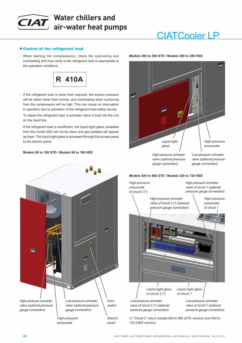
Water chillers and air-water heat pumps
HEAT PUMPS - AIR CONDITIONING - REFRIGERATION - AIR HANDLING - HEAT EXCHANGE - NA 12.122 H42
CIATCooler LP Control of the refrigerant load
- When starting the compressor(s), check the subcooling and overheating and thus verify is the refrigerant load is appropriate to the operation conditions.
R 410A
- If the refrigerant load is lower than required, the suction pressure will be rather lower than normal, and overheating when suctioning from the compressors will be high. This can cause an interruption in operation due to activation of the refrigerant load safety device.
To adjust the refrigerant load, a schrader valve is built into the unit on the liquid line.
If the refrigerant load is insuffi cient, the liquid sight glass (available from the model 200) will not be clean and gas bubbles will appear as foam. The liquid sight glass is accessed through the access panel to the electric panel.
(*) “Circuit 2” only in models 640 to 960 (STD version) and 640 to 720 (HEE version).
Models 200 to 360 STD / Models 200 to 280 HEE
Models 420 to 960 STD / Models 320 to 720 HEE
Low-pressure schrader valve (optional pressure gauge connection)
High-pressure schrader valve (optional pressure gauge connection)
High-pressurepressostat
Liquid sight glass
Liquid sight glassof circuit 2 (*)
Liquid sight glassof circuit 1
Low-pressure schradervalve of circuit 2 (*) (optional pressure gauge connection)
Low-pressure schrader valve of circuit 1 (optional pressure gauge connection)
High-pressure schradervalve of circuit 2 (*) (optional pressure gauge connection)
High-pressurepressostatof circuit 2 (*)
High-pressure schradervalve of circuit 1 (optional pressure gauge connection)
High-pressurepressostatof circuit 1
Models 90 to 180 STD / Models 90 to 180 HEE
Low-pressure schrader valve (optional pressure gauge connection)
High-pressure schrader valve (optional pressure gauge connection)
Electricpanel
High-pressurepressostat
Doorswitch

HEAT PUMPS - AIR CONDITIONING - REFRIGERATION - AIR HANDLING - HEAT EXCHANGE - NA 12.122 H
Water chillers and air-water heat pumps
43
CIA
TCoo
ler L
P
- Verify the absence of any leaks of the refrigerant. In the event of a leak:
• Completely empty the unit using a specifi c recovery unit for R-410A and repair the leak.
• Next, reload the gas into the unit according to load data provided in the technical characteristics table and in the unit's data plate.
• Add the refrigerant via the schrader valve of the liquid line, whilst the compressor is in operation, monitoring the pressures should there be any anomaly.
Cooling MODE
Compressor
Suction pressure bar
Suction temperature (1) ºC
Condensation pressure bar
Condensation temperature (2) ºC
Air condenser
Gas inlet temperature ºC
Liquid outlet temperature (3) ºC
Air inlet temperature ºC
Outdoor temperature ºC
Air outlet temperature ºC
Water evaporator
Water inlet temperature ºC
Water outlet temperature ºC
Liquid inlet temperature ºC
Evaporator outlet temperature (4) ºC
Subcooling (2) - (3) ºC
Overheating (4) - (1) ºC
Heating MODE
Compressor
Suction pressure bar
Suction temperature (1) ºC
Condensation pressure bar
Condensation temperature (2) ºC
Air evaporator
Liquid inlet temperature ºC
Gas outlet temperature (4) ºC
Air inlet temperature ºC
Outdoor temperature ºC
Air outlet temperature ºC
Water condenser
Water inlet temperature ºC
Water outlet temperature ºC
Gas inlet temperature ºC
Liquid outlet temperature (3) ºC
Subcooling (2) - (3) ºC
Overheating (4) - (1) ºC
Possible problems at commissioning
All indications given in this brochure must be respected and complied with to guarantee a correct operation of the units.
Next, several possible operation problems are stated which could happen if the conditions of the commissioning are not appropriate.
- Insuffi cient water fl ow. Very high temperature differences between water inlet into and outlet from the unit caused by:
• Insuffi cient air bleeding.
• Small water circulation pump or anti-clockwise rotation.
• Other situations which may prevent correct water circulation.
- Insuffi cient thermal charge in the installation. The limiting operating values are quickly reached by:
• Incorrect operation of the emissions system (fan coils, air conditioning exchangers, etc.).
- Air recirculation in the unit, originated by some obstacle in the air aspiration or supply.
Operational checks
Check the unit operation by verifying the electronic control and the safety devices.
It is also recommendable to create a report, taking note of the date, which includes the following information:
- the nominal voltage,
- current absorbed by the compressors, fans and other electrical components,
- signifi cant temperatures in the cooling circuit (see attached table),
- other aspects considered interesting such as alarms detected by the electronic control of the unit.
The recording of these parameters whilst the unit is running allows controlling the installation performance and it is the best possible way to avoid breakdowns since the analysis of these data makes early detection of anomalies possible or the provision of the necessary means available to ensure that they do not take place.
Schrader valve for refrigerant load

Water chillers and air-water heat pumps
HEAT PUMPS - AIR CONDITIONING - REFRIGERATION - AIR HANDLING - HEAT EXCHANGE - NA 12.122 H44
CIATCooler LP
Recommendations
- Do not lean on the unit. A platform must be used to work on a level.
- Do not lean on the copper refrigerant tubes.
- Keep the unit clean.
- Keep the space surrounding the unit clean and cleared in order to avoid accidents and ensure the proper ventilation of the coil.
- Perform a visual (remains of water or oil below or around the unit) and auditory inspection of the entire installation.
- In general, a corrosion control must be performed on the metallic parts of the unit (frame, bodywork, exchangers, electric panel, etc.).
- Check that the insulation foam is not unstuck or torn.
- All the electric connection states must be checked as well, as well as the air tightness of the different circuits.
Next, some recommendations are stated for performing the maintenance and cleaning of the unit's components:
13. MAINTENANCE
The minimal maintenance operations and their periodicity will be made according to the national regulations.
Any intervention on the electric cooling components must be made by a qualifi ed and authorized technician.
Technicians who intervene with the unit must use the necessary safety equipment (gloves, goggles, insulating clothing, safety shoes, etc.). Furthermore, if working around sources of signifi cant noise, we recommend the use of noise-dampening headgear.
V-220004
Caution: Before intervening in the unit, cut off main power.
Liquid sight glass (available from the model 200)
This sight glass, located on the liquid line, after the dehydrating fi lter, enables controlling the refrigerant load and the presence of moisture in the circuit. The presence of bubbles in the indicator means that the refrigerant fl uid load is insuffi cient (see chapter 4 "Technical characteristics") or that there are non-condensable products in the cooling circuit. The presence of moisture is characterised by the change in colour of the control paper located on the sight glass.
On CIATCooler units, the liquid sight glass is accessed via the electric panel access panel (please, consult the section “refrigerant charge load”).
Warning:
If the unit stops, certain indicators may appear in yellow; the change in colour is due to the sensitivity, which depends on the temperature of the fl uid.
These will change to green after a few hours of the unit operating.
If the indicators remain yellow, that will indicate the presence of excessive humidity in the circuit. This will require the presence of a specialist.
Air coil
- Check that the coil is free from dust and grease.
- Cleaning the accumulated dust on the coil can be performed with a vacuum cleaner perpendicular to the fi ns or with a low-pressure water cleaner. Grease can be removed with water with degreaser. Do not put stress on the fi ns as they could deform.
- I f the unit includes a protective grille for the coil (optional), it will be necessary to remove this one. The grille is fi xed by modules in the holes made for this purpose in the unit supports.
Protective grille
Access to the electric panel
Doorswitch
Liquid sight glass
Dehydrating fi lter
- The fi lter function is to keep the cooling circuit clean and without humidity, neutralising the acids that can be found in the cooling circuit.
- Verify dirt measuring the difference in temperature at the piping level, at the inlet and at the outlet of the dehydrant.
- If necessary, replace.

HEAT PUMPS - AIR CONDITIONING - REFRIGERATION - AIR HANDLING - HEAT EXCHANGE - NA 12.122 H
Water chillers and air-water heat pumps
45
CIA
TCoo
ler L
P
Plate exchanger
- The exchangers are fi tted with thermal insulation. Check that the foam is not unstuck or broken.
- The water quality and the pressure drop must be verifi ed at the ex-changer level. After verifying the mesh fi lter condition, if necessary, the exchanger must be cleaned. To this end, a weak solution of phosphoric acid 5% must be circulated using the high pressure pump. During optimum cleaning, the cleaning solution fl ow must, as a minimum, be 1,5 times the working fl ow, preferably in the inverse circulation mode. This must be followed by thorough rinsing with water to remove any acidic residues. It is advisable to circulate a solution 1%-2% of sodium hydroxide prior to the last rinsing in order to ensure that the acid has been neutralised.
- Any repair or modifi cation to the plate exchanger is prohibited. It can only be replaced by an original part.
• Access to the plates exchangers both the main circuit and the recovery circuit in models 640 to 960 STD and 420 to 720 HEE:
Because it is a dual plates exchanger, is it located in the central area of the unit, on the axis of symmetry of the two circuits. If the exchanger have to be replaced, the two panels indicated in this image must be removed.
Dehydratingfi lters
Plates exchager Panels
- To be able to unscrew the water connections of the exchanger, the unit incorporates another movable panel which is accessed by the door on the left side of the above door. By registering also accessed the recovery exchanger.
Plate exchangerof the main circuit
Plate exchanger of the recovery circuit
Water threaded conections
In the following image it is possible to observe the plate exchanger of the main circuit extracted .
Accesspanel
Mesh fi lter- It is also necessary to install a fi lter in the hydraulic power
supply to the unit in order to prevent clogging of the plate exchanger.
- For LPC/ILPC units, a kit with a stainless steel mesh fi lter (500 microns) is also supplied for installation by the installer. Optionally, this fi lter can be supplied for LP/ILP units.
- The fi ltering mesh must be removed and cleaned in order to clean the fi lter.

Water chillers and air-water heat pumps
HEAT PUMPS - AIR CONDITIONING - REFRIGERATION - AIR HANDLING - HEAT EXCHANGE - NA 12.122 H46
CIATCooler LPCentrifugal fan (STD version)
- Verify that the turbine and the motor remain clean.
- Foresee having a spare belt set for the fans.
- The motors and the fans have bearings that have been lubricated and sealed and, thus, do not need further lubrication (except in the case of fans with a reinforced shaft).
Servomotor (optional)
In CIATCooler units with a condensation pressure regulation damper (in the STD version), it is advisable to check the state of the servomotor.
Note: The damper in models 420V-STD to 600V-STD incorporates 2 sevomotors (one on each side).
Pump
In the case of pump replacement:
- Disconnect the unit from power supply.
- Disconnect electrically the pump.
- Empty completely of water from the hydraulic circuit.
- Loosen the fi ttings of the 2 pipes.
- Remove the two screws fi xing the pump and replace it.
Condensate pan Drain
Filter in the return air (optional)
- Clean usually. Depending on the installation conditions, the fi lter aspect must be examined to defi ne the cleaning periodicity.
- Gravimetric fi lters: Cleaning the fi ltering mesh can be done with a household vacuum cleaner, or by submerging it in water.
Filters are moved by lifting the tab
and dragging
CIATCooler Number of frames Number of cell90V-STD to 100V-STD 1 2
120V-STD to 180V-STD 1 3
200V-STD 2 4
240V-STD to 600V-STD 2 6
640V-STD to 960V-STD 2 16
90V-HEE 1 2
100V-HEE to 120V-HEE 1 3
160V-HEE to 180V-HEE 2 4
200V-HEE to 360V-HEE 2 6
420V-HEE to 720V-HEE 2 16
Condensate drain pan
- Check that the condensate pan is clean.
- Check that the drain is not clogged.
- Cleaning of the pan can be done with water and non-abrasive detergent.

HEAT PUMPS - AIR CONDITIONING - REFRIGERATION - AIR HANDLING - HEAT EXCHANGE - NA 12.122 H
Water chillers and air-water heat pumps
47
CIA
TCoo
ler L
P
Refrigerant
Only qualifi ed personnel must perform a periodic tightness control, in accordance with the regulation (CE) Nº 517/2014.
- The frequency of checks is no longer related to the load of refrigerant but to its global warming potential:
Load kg x GWP = t CO2e
Carbon dioxide equivalency (t CO2e ) is a quantity that describes, for a given mixture and amount of greenhouse gas, the amount in tonnes of CO2 that would have the same global warming potential (GWP).
Please, consult data of carbon dioxide equivalency (t CO2e) provided in the technical characteristics table (chapter 4).
- Operators shall ensure that the unit is checked for leaks ad minima according to the following frequency:
• t CO2e < 5 ............ not subjected
• t CO2e 5 to 50 ...... every year
• t CO2e 50 to 500 ... every 6 months
• t CO2e > 500 ......... every 3 months
- Where a leakage detection system has been installed the frequency of checks is halved.
Note: Never forget that the cooling systems contain liquids and vapours under pressure. The service pressure of R-410A is approximately 1.5 higher than that of R-407C.
- All necessary precautions must be taken during the partial opening of the cooling circuit. This opening entails the discharge of a certain amount of refrigerant to the atmosphere. It is essential to limit this quantity of lost refrigerant to a minimum by pumping and isolating the charge in some other part of the circuit.
- The refrigerant fl uid at low temperature can cause infl ammatory in-juries similar to burns when contacting the skin or eyes. Always use safety goggles, gloves, etc. when opening ducts that may contain liquids.
- The refrigerant in excess must be stored in appropriate containers and the amount of refrigerant stored at the technical rooms must be limited.
- Refrigerant barrels and deposits must be handled with precaution and visible warning signs must be placed to attract attention over the risks of intoxication, fi re and explosion linked to the refrigerant.
- At the end of its useful life, the refrigerant must be retrieved and recycled as per the current regulations.
Oil
Oils used for cooling machines do not post any threat to one's health if used while following the usage guidelines:
- Avoid any unnecessary manipulation of the elements covered in oil. Use protection creams.
- Oils are fl ammable and must be stored and handled with precaution. "Disposable" rags or towels used for cleaning must be kept away
Compressor
In the case of compressor replacement:
- Disconnect the unit from power supply.
- Completely empty the load of refrigerant using a specifi c recovery unit for R-410A
- Disconnect electrically the compresor.
- Carefully unscrew the suction and discharge piping.
- The compressor is fi xed onto the platform with 4 screws Ø 8 mm. Unscrew the fi xings.
- Place the new compressor and check that it has a suffi cient oil charge.
Warning: when tightening the compressor screws, please consult the maximum torque that can be applied.
If a torque wrench is not available, tighten them until noticing resistance, then tighten the screws by turning them 3/4 of a revolution.
- Screw the suction and discharge piping.
- Connect the compressor in accordance with the circuit diagram.
- Make vacuum and next, reload the gas into the unit according to load data provided in the technical characteristics table and in the unit’s data plate.
from open fl ames and must be discarded by using the appropriate procedure.
- Jugs must be kept closed. Avoid using oil from an already-open jug kept in poor conditions.
Both the oil type as well as the volume needed for each model are stated in the characteristics table in chapter 4.
- Check the oil level and aspect. In case of a colour change, check the oil quality using a contamination test.
- In the case of the presence of acid, water or metallic particles, replace the affected circuit oil, as well as the dehydrant fi lter.
- In the event of an oil charge change, only new oil will be used, which will be identical to the original oil and taken from a jug tightly closed until the moment of the charge.

Water chillers and air-water heat pumps
HEAT PUMPS - AIR CONDITIONING - REFRIGERATION - AIR HANDLING - HEAT EXCHANGE - NA 12.122 H48
CIATCooler LP14. CONTROL AND ANALYSIS OF BREAKDOWNS
Symptom Cause Solution
Evaporation pressure very high in relation with the air or water inlet
a) Charge excessb) High water temperaturec) Compressor suction not air tightd) Cycle reversing valve in middle position
a) Collect refrigerantb) Verify overheatingc) Verify compressor state and replaced) Check that the valve is not clogged. Replace
if necessary
Very low condensation pressure a) Gas lackb) Low water temperaturec) Compressor suction not air tightd) Cycle inversion valve in middle position
e) Liquid circuit plugging
a) Search for leaks, complete chargeb) Wait for regular speedc) Verify compressor state and replaced) Check that the valve is not clogged. Replace
if necessarye) Verify the dehydrating fi lter and expansion
valve
Condensation pressure very high in relation to the air or water outlet, high pressure pressostat cut-off
a) Air or water fl ow insuffi cient
b) Air or water inlet temperature very highc) Dirty condenser (does not exchange)d) Much refrigerant load (fl ooded condenser)e) The condenser fan is broken downf) Air in the cooling circuit
a) Verify the air or water circuits (fl ow, fi lter cleanliness etc.)
b) Verify the control thermostat readjustmentc) Clean itd) Collect refrigerante) Repairf) Make vacuum and load
Evaporation pressure too low (low pressostat cut-off)
a) Low fl ow in evaporator. Air recirculation
b) Frozen evaporatorc) Liquid line as different temperatures at fi lter
inlet and outletd) Gas lacke) Very low condensation pressure
f) Evaporator fan broken down
a) Verify the air or water circuits (fl ow, fi lter cleanliness etc.)
b) Verify defrostc) Replace fi lter
d) Search for leaks, complete chargee) Temperature of air or water in condenser
very low (air or water fl ow very high), adjust fl ow
f) Repair
Compressor does not start, does not make noise (humming)
a) No powerb) The contacts of a control element are openc) Timing of anti cycle short does not allow the
startingd) Open contacte) Contactor coil burntf) Indoor Klixon open
a) Check differential, fusesb) Verify the safety chain of the electronic
controlc) Verify electronic controld) Replacee) Replacef) Wait for reactivation, verify intensity absorbed
Compressor does not start, motor sounds intermittently
a) Electrical power supply very lowb) Power cable disconnected
a) Control line voltage and locate voltage drop b) Verify connections
Repeated compressor starts and stops a) Because of high pressureb) Control differential too short (short cycle)c) Insuffi cient gas, cut-off because of low
pressured) Dirty or frosted evaporatore) The evaporator fan does not work, cuts off
the low pressostatf) Expansion valve damaged or clogged by
impurities (cuts off low pressostat)g) Dehydrating fi lter clogged (cuts off low
safety)
a) Verify chargeb) Increase differentialc) Search for leak, reload unit
d) Clean, verify evaporator air circuite) Replace or repair
f) Replace, as well as fi lter
g) Replace
The compressor makes a noise a) Loose attachmentb) Oil lackc) Compressor noise
a) Fixb) Add oil to recommended levelc) Replace
Noisy operation a) Unit installed without antivibration protection a) Place base over shock absorbers
Cycle reversing is not carried out:- No defrosting- Does not change winter - summer cycles
a) Electrical faultb) Inversion valve coil defectivec) Defrost method not workingd) Cycle inversion valve in middle position
e) Control fault
a) Locate and repairb) Replacec) Verify parametersd) Tap with running compressor Replace if
necessarye) Locate and repair

HEAT PUMPS - AIR CONDITIONING - REFRIGERATION - AIR HANDLING - HEAT EXCHANGE - NA 12.122 H
Water chillers and air-water heat pumps
49
CIA
TCoo
ler L
P
ANNEX I: QUICK OVERVIEW OF THE INSTALLATION
Air-cooled chillers / air-water heat pumps
Installation sketch and units location
TelephoneInstaller
Responsible for installation and/or commissioning
Installation / work reference
Address
Unit Unit model Serial number Date for commissioning

Water chillers and air-water heat pumps
HEAT PUMPS - AIR CONDITIONING - REFRIGERATION - AIR HANDLING - HEAT EXCHANGE - NA 12.122 H50
CIATCooler LP
Curve ______________
Curve ______________
• Unit connections .................................................................................................
• Cut-off valves ......................................................................................................
• Circuit: Open Closed
• Operating nominal pressure _______ kg/cm2
• Buffer tank________litres and/or circuit water total capacity _______ litres
• Expansion vessel and safety valve.....................................................................
• Air drain done .....................................................................................................
• Flow controller checking .....................................................................................
• Hydraulic circuit cleaning ....................................................................................
• Water fi lter at the unit inlet (Mesh for particles > 0.5 mm) ........................
• Thermometers at the inlet and outlet of the unit .................................................
• Constant water fl ow in unit _____________m3/h
• Circulation pump. Primary (unit) .........................................................................
• Circulation pump. Secundary (emission system) ...............................................
• Emission control system: Two ways ............................................... Three ways ............................................• Manometers reading (m.w.c.)
Pump: Suction __________Discharge ________ Diff _______ Unit: Inlet _____________Outlet ____________ Diff ________
• Complete operation emission system (air-conditioner, fan-coil, etc)
Electrical connections
POWER ................................................................................................... YES
• Provisional voltage _____ V
• Final Voltage _____ V + T + N
• Line protection type
Fuse
Automatic
CONTROL
• On / off external control ......................................................................................
• Cooling / heating external selector (only if necessary) .......................................
• Unit operation circuit interlock / circulation pumps .............................................
Unit with voltage from _____ day ________ hour__________
Connections and components of the
hydraulic circuit
A A
Observations
• Date __________________________ Signed:
Available power_____kW
NO
YES NO
YES NO
YES NO

