christchurch city council construction standard...
TRANSCRIPT
CHRISTCHURCH CITY COUNCIL CONSTRUCTION STANDARD SPECIFICATION
PART 3 – UTILITY DRAINAGE
CSS: PART 3 2014
TABLE OF CONTENTS
1.0 FOREWORD........................................................................................................................1
2.0 RELATED DOCUMENTS..................................................................................................1
3.0 APPROVAL OF MATERIALS, OPERATORS/CONTRACTORS, EQUIPMENT, LABORATORIES AND WORKMANSHIP .....................................................................3
4.0 PRIVATE PROPERTY.......................................................................................................3 4.1 Progress of Work ............................................................................................................4 4.2 Planting and Existing Structures...................................................................................4 4.3 Excavated Material .........................................................................................................4 4.4 Approved Equipment .....................................................................................................4 4.5 Temporary Fencing.........................................................................................................4 4.6 Measurement of Work and Basis of Payment ..............................................................5
5.0 EXISTING SERVICES .......................................................................................................5 5.1 Support of Services .........................................................................................................5
5.1.1 Live Laterals Crossing the Excavation...................................................................................5 5.1.2 Support of Sewer or Stormwater Pipes Crossing the Excavation ..........................................5 5.1.3 Asbestos Watermains .............................................................................................................5
5.2 Service Conflicts ..............................................................................................................6 5.2.1 Abandoned Services...............................................................................................................6 5.2.2 Live Laterals Fouled by the Proposed Pipeline......................................................................6 5.2.3 Unavoidable Diversion of Services........................................................................................6 5.2.4 Clearance to Other Services ...................................................................................................6
5.3 Redundant and Abandoned Services ............................................................................7 5.3.1 Clashing Services ...................................................................................................................7 5.3.2 Manholes................................................................................................................................7 5.3.3 Wastewater and stormwater pipes..........................................................................................7
5.4 Measurement of Works and Basis of Payment.............................................................8 5.4.1 Support of Services Alongside the Excavation ......................................................................8 5.4.2 Support of Power Poles..........................................................................................................8 5.4.3 Support of Services Crossing the Excavation ........................................................................8 5.4.4 Laterals Crossing the Excavation...........................................................................................8 5.4.5 Unavoidable Diversion of Services........................................................................................8 5.4.6 Clearance to Other Services ...................................................................................................8 5.4.7 Potholing Services..................................................................................................................8 5.4.8 Clashing Services ...................................................................................................................8 5.4.9 Manholes................................................................................................................................8 5.4.10 Wastewater and stormwater pipes..........................................................................................9
6.0 EXCAVATION ....................................................................................................................9 6.1 Excavations in Legal Road .............................................................................................9 6.2 Temporary Sealing..........................................................................................................9
CSS: Part 3 2014 printed 30/04/14 i
6.3 Removal and Disposal of Surplus Excavated Material................................................9 6.4 Trench Excavation ..........................................................................................................9
6.4.1 Length of Open Trench ..........................................................................................................9 6.4.2 Trench Width .......................................................................................................................10 6.4.3 Base of Excavation...............................................................................................................10 6.4.4 Trench Support.....................................................................................................................10 6.4.5 Trench In An Existing Watercourse.....................................................................................11 6.4.6 Installation of Geotextiles ....................................................................................................11
6.5 Excavations for Structures ...........................................................................................11 6.6 Rock and Explosives .....................................................................................................11
6.6.1 Rock Definition....................................................................................................................11 6.6.2 Use of Explosives.................................................................................................................11
6.7 Dewatering.....................................................................................................................12 6.7.1 Keeping the Excavation Free of Water ................................................................................12 6.7.2 Control of Pumped Water ....................................................................................................12 6.7.3 Dewatering of Peat...............................................................................................................12
6.8 Stumps and Subsurface Objects ..................................................................................12 6.8.1 Stumps..................................................................................................................................12 6.8.2 Subsurface Objects...............................................................................................................13
6.9 Measurement of Works and Basis of Payment...........................................................13 6.9.1 Excavation............................................................................................................................13 6.9.2 Unsuitable Foundations........................................................................................................13 6.9.3 Temporary Sealing ...............................................................................................................13 6.9.4 Trench In An Existing Watercourse.....................................................................................13 6.9.5 Installation of Geotextiles ....................................................................................................13 6.9.6 Trench Support Left in Position...........................................................................................14 6.9.7 Rock Excavation ..................................................................................................................14 6.9.8 Keeping the Excavation Free of Water ................................................................................14 6.9.9 Stumps and Subsurface Objects ...........................................................................................14
7.0 JOINTING..........................................................................................................................14 7.1 Mechanical Jointing......................................................................................................14 7.2 Jointing of PVC-m and PVC-u Pipe............................................................................15 7.3 Thermoplastic Jointing of Polyethylene Pipe by Electrofusion Welding.................15
7.3.1 Methodology ........................................................................................................................15 7.3.2 Quality Assurance Records ..................................................................................................15 7.3.3 Operator Qualifications........................................................................................................16 7.3.4 Equipment ............................................................................................................................16 7.3.5 Pipe Preparation ...................................................................................................................17 7.3.6 Welding................................................................................................................................17 7.3.7 Pipeline Recovery after Pulling in/Cooling of Heated Pipe.................................................18
7.4 Site Butt Fusion Jointing of Polyethylene Pipe and Fittings .....................................18 7.4.1 Methodology ........................................................................................................................19 7.4.2 Quality Assurance Records ..................................................................................................19 7.4.3 Operator Qualifications........................................................................................................20 7.4.4 Equipment ............................................................................................................................20 7.4.5 Pipe Preparation ...................................................................................................................21 7.4.6 Welding................................................................................................................................22 7.4.7 Bead Profile..........................................................................................................................22 7.4.8 Joint Failure during Handling and Installation.....................................................................23
7.5 Measurement of Works and Basis of Payment...........................................................23
8.0 PIPE INSTALLATION .....................................................................................................23 8.1 Line and Level ...............................................................................................................23
8.1.1 Lasers ...................................................................................................................................23 8.1.2 Use of Lasers........................................................................................................................24
CSS: Part 3 2014 printed 30/04/14 ii
8.2 Cutting ...........................................................................................................................24 8.3 Cleanliness .....................................................................................................................24 8.4 Leaks ..............................................................................................................................24 8.5 Pipe Protection ..............................................................................................................25
8.5.1 Haunching and Surround .....................................................................................................25 8.5.2 Concrete Capping.................................................................................................................25 8.5.3 Concrete Surround ...............................................................................................................26 8.5.4 Concrete Protection Slab to PVC Pipes ...............................................................................26 8.5.5 Joint Formers........................................................................................................................26 8.5.6 Geotextiles ...........................................................................................................................26 8.5.7 Pipe foundations...................................................................................................................26
8.6 Pipe Installation on Hillsides........................................................................................26 8.6.1 Treatment of Under-runners.................................................................................................26 8.6.2 Water stops...........................................................................................................................26
8.7 Flexible Pipes .................................................................................................................26 8.8 Pressure Pipelines .........................................................................................................27
8.8.1 Thrust blocks........................................................................................................................27 8.8.2 Anchor blocks ......................................................................................................................27 8.8.3 Valves and surface covers....................................................................................................27
8.9 Subsoil Drains................................................................................................................28 8.10 Pipelaying at Structures ...............................................................................................28
8.10.1 Yield Joints ..........................................................................................................................28 8.10.2 Underchannel Piping............................................................................................................28 8.10.3 Starters/Finishers..................................................................................................................28 8.10.4 Polyethylene Connection to Manholes.................................................................................28 8.10.5 Long Socket Connectors ......................................................................................................29 8.10.6 Collector sewers ...................................................................................................................29
8.11 Measurement of Works and Basis of Payment...........................................................29 8.11.1 Pipe Installation....................................................................................................................29 8.11.2 Pipe Protection and Haunching............................................................................................29 8.11.3 Geotextiles ...........................................................................................................................30 8.11.4 Treatment of Under-runners.................................................................................................30 8.11.5 Water stops...........................................................................................................................30 8.11.6 Thrust blocks........................................................................................................................30 8.11.7 Subsoil Drains ......................................................................................................................30 8.11.8 Pipelaying at Structures........................................................................................................30
9.0 POLYETHYLENE PIPE INSTALLATION...................................................................30 9.1 Pipe Installation by Trenchless Technology ...............................................................31
9.1.1 Polyethylene Pipe Installation by Pipebursting....................................................................31 9.1.2 Polyethylene Pipe Installation by Slip Lining......................................................................31 9.1.3 Polyethylene Pipe Installation by Directional Drilling ........................................................31
9.2 Access Pits......................................................................................................................32 9.3 Pressure Sewer Systems................................................................................................33 9.4 Measurement of Works and Basis of Payment...........................................................33
9.4.1 Pipe Installation in Open Trenches ......................................................................................33 9.4.2 Pipe Installation by Pipebursting .........................................................................................33 9.4.3 Pipe Installation by Slip Lining............................................................................................33 9.4.4 Pipe Installation by Directional Drilling ..............................................................................33
10.0 JUNCTIONS AND RISERS..............................................................................................34 10.1 Junctions ........................................................................................................................34 10.2 Risers ..............................................................................................................................34 10.3 End Plugging .................................................................................................................34
CSS: Part 3 2014 printed 30/04/14 iii
10.4 Polyethylene Junctions and Adaptors .........................................................................34 10.5 Measurement of Works and Basis of Payment...........................................................34
10.5.1 Junctions ..............................................................................................................................34 10.5.2 Risers....................................................................................................................................35
11.0 LATERALS ........................................................................................................................35 11.1 Laterals in Close Proximity to Trees ...........................................................................35 11.2 Sewer Lateral Cover at Lot Boundary........................................................................35 11.3 End Capping and Marking ..........................................................................................35 11.4 Lateral/Mainline Sequence...........................................................................................36 11.5 Fluming of Disconnected Laterals ...............................................................................36 11.6 Laterals into Polyethylene Pipe....................................................................................36 11.7 Connecting to Existing Laterals...................................................................................36 11.8 Measurement of Works and Basis of Payment...........................................................36
11.8.1 Laterals Requiring Structural Maintenance..........................................................................36 11.8.2 Laterals into Polyethylene Pipe............................................................................................36
12.0 STRUCTURES...................................................................................................................37 12.1 Reference Documents....................................................................................................37 12.2 Quality Assurance .........................................................................................................37
12.2.1 Contract Quality Plan...........................................................................................................37 12.2.2 Personnel..............................................................................................................................37
12.3 Reinforcement ...............................................................................................................38 12.4 Formwork ......................................................................................................................39
12.4.1 Construction Requiring Support From Other Permanent Works .........................................39 12.5 Precast Concrete Shop Drawings ................................................................................41 12.6 Embedded Items............................................................................................................42
12.6.1 Knock Out Panels.................................................................................................................42 12.7 Construction Joints .......................................................................................................43 12.8 Supply of Concrete........................................................................................................43 12.9 Concrete Placing, Finishing and Curing.....................................................................44
12.9.1 Precast Concrete...................................................................................................................46 12.9.2 Slabs .....................................................................................................................................46
12.10 Precast Concrete Handling, Transportation and Erection .......................................47 12.10.1 Tolerances ............................................................................................................................47
12.11 Manholes ........................................................................................................................47 12.11.1 Special Construction Joint....................................................................................................47 12.11.2 Manhole Benching and Channelling....................................................................................48 12.11.3 Joints Between Precast Risers ..............................................................................................48 12.11.4 Precast Manhole Tops ..........................................................................................................48 12.11.5 New Manhole on an Existing Pipeline.................................................................................48 12.11.6 New Pipe Invert in Existing Manhole ..................................................................................48 12.11.7 Manhole Openings ...............................................................................................................48
12.12 Flush Tanks and Manholes ..........................................................................................49 12.12.1 Flush Tanks ..........................................................................................................................49 12.12.2 Flush Manholes ....................................................................................................................49
12.13 Frames and Lids............................................................................................................49 12.14 Air Gap Separators.......................................................................................................49 12.15 Other Minor Structures................................................................................................49 12.16 Concrete Repair ............................................................................................................49
CSS: Part 3 2014 printed 30/04/14 iv
12.17 Compliance Testing.......................................................................................................50 12.18 Measurement of Works and Basis of Payment...........................................................50
12.18.1 Concrete Construction..........................................................................................................50 12.18.2 Manholes..............................................................................................................................50 12.18.3 Flush Tanks and Manholes ..................................................................................................51 12.18.4 Air Gap Separators...............................................................................................................51 12.18.5 Other Minor Structures ........................................................................................................51 12.18.6 Concrete Repair....................................................................................................................51
13.0 CONNECTIONS AND ALTERATIONS TO EXISTING SYSTEM............................51 13.1 Measurement of Works and Basis of Payment...........................................................52
14.0 PERFORMANCE TESTING............................................................................................52 14.1 Equipment......................................................................................................................52 14.2 Gravity Pipelines ...........................................................................................................52
14.2.1 Structures .............................................................................................................................53 14.2.2 Testing Junctions..................................................................................................................53 14.2.3 Visual Inspection..................................................................................................................53 14.2.4 Hydrostatic Test ...................................................................................................................53 14.2.5 Air Test ................................................................................................................................54 14.2.6 CCTV Inspection .................................................................................................................54
14.3 Pressure Pipelines .........................................................................................................55 14.3.1 Concrete Pipe .......................................................................................................................55 14.3.2 Polyethylene Pipe up to DN 315..........................................................................................56 14.3.3 Polyethylene Pipe over DN 315...........................................................................................57 14.3.4 Self Tapping Electrofusion Saddles .....................................................................................57 14.3.5 PVC, Ductile Iron, Glass Reinforced Plastic Pipe ...............................................................57
14.4 Vacuum Sewer Tests .....................................................................................................57 14.5 Polyethylene Pipe Weld Tests ......................................................................................57
14.5.1 Pre-construction Joint Testing – Electrofusion ....................................................................58 14.5.2 Pre-construction Joint Testing – Electrofusion Saddles.......................................................58 14.5.3 Pre-construction Joint Testing – Butt Fusion.......................................................................58 14.5.4 Joint Testing During Construction – Electrofusion..............................................................59 14.5.5 Joint Testing During Construction –Electrofusion Saddles .................................................59 14.5.6 Joint Testing During Construction – Butt Fusion ................................................................60 14.5.7 Joint Test Failures ................................................................................................................60
14.6 Flexible Pipe Ovality Test.............................................................................................62 14.7 Measurement of Work and Basis of Payment ............................................................62
14.7.1 Testing Junctions..................................................................................................................62 14.7.2 CCTV inspection..................................................................................................................62 14.7.3 Polyethylene Pipe Weld Test ...............................................................................................62
15.0 BACKFILLING .................................................................................................................63 15.1 Prior to Backfilling........................................................................................................63 15.2 Materials ........................................................................................................................63 15.3 Backfill Procedure.........................................................................................................63 15.4 Quality Assurance .........................................................................................................63 15.5 Measurement of Works and Basis of Payment...........................................................64
15.5.1 Imported Backfill .................................................................................................................64 15.5.2 Filling to Unsuitable Foundations........................................................................................64 15.5.3 Testing..................................................................................................................................64
16.0 ADJUSTING MANHOLES TO ALTERED SURFACE LEVELS ...............................64 16.1 Materials ........................................................................................................................65 16.2 Raising of Manhole Frames .........................................................................................65
CSS: Part 3 2014 printed 30/04/14 v
CSS: Part 3 2014 printed 30/04/14 vi
16.2.1 Raising the Frame for a Standard Manhole within the Rebate.............................................65 16.2.2 Raising the Frame for a Bottleneck Manhole.......................................................................65 16.2.3 Deepening the Rebate ..........................................................................................................65
16.3 Raising of Manhole Tops..............................................................................................65 16.3.1 Standard Manholes...............................................................................................................66 16.3.2 Bottleneck Manholes............................................................................................................66 16.3.3 Precast Circular Manholes ...................................................................................................66
16.4 Lowering the Surface Level..........................................................................................66 16.4.1 Standard Manholes without Vents .......................................................................................66 16.4.2 Standard Vented Manholes with Removable Vent Gratings................................................66 16.4.3 Vented Manholes with a Fixed Vent Grating.......................................................................66 16.4.4 Bottleneck manholes. ...........................................................................................................66 16.4.5 Precast Circular Manholes ...................................................................................................67
16.5 Protection of System .....................................................................................................67 16.6 Protection of Structures................................................................................................67 16.7 Measurement of Works and Basis of Payment...........................................................67
16.7.1 Manholes Adjusted Separately from Drainage Works.........................................................67
17.0 RESTORATION ................................................................................................................67 17.1 Measurement of Works and Basis of Payment...........................................................67
Christchurch City Council Civil Engineering Construction Standard Specification
APPENDICES
1 Concrete Construction Checklist
2 General Requirements for Site Butt Fusion Jointing
3 Electrofusion Welding Checksheet
4 Compliance Requirements Checksheet
5 Pipe Butt Weld Record Log Sheet
6 Pipe Electrofusion Weld Record Log Sheet STANDARD DETAILS
Iron Work Details SD 301/1 Circular Manhole Frames and Covers
SD 301/2 Manhole Vent & Trafficable House Drain
Sump Frames & Covers
SD 301/3 Corner Sump Frame & Covers
SD 301/4 detail deleted Revision 8.0
SD 301/5 Wavy Sump Grating and Frame
SD 301/6 Standard Sump Grating and Frame
SD 301/7 Rectangular & Double Manhole Frames &
Covers
Manholes SD 302/1 Square Manholes Cast In-situ
SD 302/2 Square and Double Manhole Tops
SD 302/3 Square Manhole Tops Reinforcement
SD 303/1 Circular Precast Manholes for Pipes up to 400ø
OD
SD 303/2 Circular Precast Manholes for Pipes up to 400ø
OD - Top Slabs Reinforcement
SD 303/3 Square Base Precast Manholes for Pipes up to
750ø
SD 303/4 Benching Junctions and Laterals in Manholes
SD 304 Inaccessible Manhole
SD 305/1 Drop Structure in Manholes
SD 305/2 Pressure Sewer Discharge into Manholes with
Drop Structure
SD 306/1 Manhole Raising Top Adjustment
SD 306/2 Manhole Raising Bottleneck Frame Adjustment
Flush Tanks SD 311/1, 2 Flush Tanks
CSS: Part 3 2014 printed 30/04/14 a

Christchurch City Council Civil Engineering Construction Standard Specification
SD 312 Flush Manholes
SD 313 Air Gap Separator
Sumps SD 321/1, 2 Side Entry Sumps - Precast Kerb Unit
SD 322/1 Side Entry Enlarged Sump
SD 322/2 Single Enlarged Sump
SD 323 detail deleted Revision 1.0
SD 324/1 Hillside Sump
SD 324/2 Special Entry to Double Sump in Hillside
Channel
SD 325 Single & Double Sumps - Flat Channel
SD 326 detail deleted Revision 1.0
SD 327 Corner Sump
SD 328 House Drain Sump and Small Trafficable Sump
SD 329 Submerged Outlet
Under Channel Piping SD 331 Concrete Surround for Under Channel Piping
225ø - 300ø
SD 332 Concrete Capping for Under Channel Piping
375ø - 525ø
Pipelaying SD 341/1 Pipelaying at Manholes & Sumps Concrete
Pipes
SD 341/2 Pipelaying at Manholes & Sumps for PVC
Pipes
SD 341/3 Pipelaying at Manholes for PE Pipes
SD 341/4 Corbels
SD 341/5 Pressure Pipelaying at Manholes for PE pipes
SD 342 Pipe Protection
SD 343 PVC Manhole Starters and Finishers
SD 344/1 Pipelaying Haunching Details for Concrete
Pipes
SD 344/2 Pipelaying Haunching Details for Flexible
Pipes
SD 344/3 Soft Ground Foundation
SD 345 detail renamed SD 344/2 Revision 1.0
SD 346 Pressure Pipelines - Thrust Blocks
SD 347 Water Stops
SD 348 detail renamed SD 342 Revision 1.0
SD 349 detail deleted Revision 1.0
Pipe Connections SD 361 Direct Connections to Stormwater Pipe
CSS: Part 3 2014 printed 30/04/14 b
Christchurch City Council Civil Engineering Construction Standard Specification
SD 362 detail deleted Revision 1.0
SD 363 Pipelaying Junctions off Factory Moulded Riser
SD 364/1 PE Junctions – Swept Bends, Inspections &
Adaptors
SD 364/2 PE Lateral to PVC Main Connector
SD 365 detail combined with SD 364 Revision 1.0
Stormwater Structures SD 371/1 Concrete Headwalls
SD 371/2 Cut Pipe Rockwall
SD 372 Standard Reinforced Concrete Beam
SD 373 detail deleted Revision 7.0
SD 374/1, 2 detail deleted Revision 7.0
SD 375 Standard Inspection Chambers Type B and
Type C
SD 376 Standard Circular Inspection Chamber
SD 377/1, 2 Subsoil Drains
SD 377/3 Subsoil Drain Pipes
SD 378 House Drain Inspection Box
Miscellaneous SD 381 Vacuum Column Backflow Preventer
SD 382 Wastewater Spindle Cap
SD 383 Pressure Sewer Flushing Point
SD 384 Pressure Sewer Trafficable Property Boundary
Kit
CSS: Part 3 2014 printed 30/04/14 c

Christchurch City Council Civil Engineering Construction Standard Specification
CSS: Part 3 2014 printed 30/04/14 d
Christchurch City Council Civil Engineering Construction Standard Specification
1.0 FOREWORD
This Specification forms Part 3 of the Christchurch City Council Civil Engineering Construction Standard Specification (abbreviated as CSS). All parts of the CSS should be read in conjunction with each other and the Infrastructure Design Standards (abbreviated as IDS). The full Specification includes the following Parts: CSS: Part 1 2014 - General CSS: Part 2 2014 - Earthworks CSS: Part 3 2014 - Utility Drainage CSS: Part 4 2014 - Water Supply CSS: Part 5 2014 - Lights CSS: Part 6 2014 - Roads CSS: Part 7 2014 - Landscapes Part 3 of the Standard Specification includes the Standard Details (SD) relating to this part only. The Standard Details (SD) are not to scale and all units are in millimetres (mm) unless otherwise shown. All rights reserved on Standard Details.
2.0 RELATED DOCUMENTS The following documents shall be read and form part of this standard specification, together with revisions, replacements and amendments up to the date of calling tenders. The requirements of this specification supersede the requirements of any related documents listed or referred to within this specification. Where this document is referred to in a contract, the requirements of that contract supersede the requirements of this specification.
NZS 3101:2006 Concrete structures standard
NZS 3104: 2003 Specification for concrete production
NZS 3109: 1997 Concrete construction
NZS 3114: 1987 Specification for concrete surface finishes
NZS 5821.2: 1981 Plain language code of practice for the safe use of
lasers in surveying, levelling and alignment
AS/NZS 1554.3: 2008 Structural steel welding - Welding of reinforcing
steel
AS/NZS 2032: 2006 Installation of PVC pipe systems
AS/NZS 2033: 2008 Installation of polyethylene pipe systems
AS/NZS 2566.2: 2002 Buried flexible pipelines - Installation
AS/NZS 4671: 2001 Steel reinforcing materials
CSS: Part 3 2014 1 printed 30/04/14
Christchurch City Council Civil Engineering Construction Standard Specification
AS 1289.5.6.1: 1998 Soil compaction and density tests - Compaction
control test - Density index method for a cohesionless
material.
AS 3996: 2006 Access covers and grates
ISO 13953: 2001 Polyethylene (PE) pipes and fittings -- Determination
of the tensile strength and failure mode of test pieces
from a butt-fused joint
ISO 13954:1997 Plastics pipes and fittings -- Peel decohesion test for
polyethylene (PE) electrofusion assemblies of
nominal outside diameter greater than or equal to 90
mm
ISO 13955:1997 Plastics pipes and fittings -- Crushing decohesion test
for polyethylene (PE) electrofusion assemblies
ASTM F2620 - 12 Standard Practice for Heat Fusion Joining of
Polyethylene Pipe Fittings
WIS 4-32-08 UK Water Industry Specification for the Fusion
Jointing of Polyethylene Pressure Pipeline Systems
Using PE 80 and PE 100 Materials (may be referred
to for general guidance)
Transit New Zealand Standard Specifications
National Code for Utility Operators’ Access to Transport Corridors
http://www.nzuag.org.nz/national-
code/CodeNov11.pdf
Christchurch City Council Schedule of Local and Special Conditions to the
National Code for Utility Operators’ Access to
Transport Corridors 2013
Christchurch City Council CCTV for Christchurch City Council Earthquake
Recovery
http://www.ccc.govt.nz/business/constructiondevelop
ment/constructionstandardspecification.aspx
Water Services Association of Australia WSA-06 Vacuum Sewerage Code of
Australia
American Prestressed Concrete Institute Recommended Practice for Erection of
Precast Concrete: 1985
New Zealand Waste Water Association New Zealand Pipe Inspection Manual
3rd edition 2006
Plastic Industry Pipe Association of Australia (PIPA) POP001 Industry
Guidelines for Electrofusion Jointing of PE Pipe and
CSS: Part 3 2014 2 printed 30/04/14
Christchurch City Council Civil Engineering Construction Standard Specification
Fittings for Pressure Applications Version 7.0
http://pipa.com.au/images/pdf/POP001.pdf
Plastic Industry Pipe Association of Australia (PIPA) POP003 Industry
Guidelines for Butt Fusion Jointing of PE Pipes and
Fittings - Recommended Parameters Version 6.0
http://pipa.com.au/images/pdf/POP003.pdf
3.0 APPROVAL OF MATERIALS, OPERATORS/CONTRACTORS, EQUIPMENT, LABORATORIES AND WORKMANSHIP
‘Approved’ in this document means approved by the Engineer unless otherwise specified. Schedules of approved materials and contractors can be found on the Christchurch City Council web page at: www.ccc.govt.nz/business/constructiondevelopment/approvedmaterials.aspx www.ccc.govt.nz/business/constructiondevelopment/approvedcontractors.aspx Selected materials are specified in CSS: Part 1 - General. All pipe and fittings shall be approved. Approved testing laboratories are IANZ accredited to carry out the particular test being requested. Imported lime stabilised fill materials shall be centrally batched off site. Site batching shall only be permitted at the discretion of the Engineer and when the Engineer is satisfied that there is appropriate equipment and space on site for thorough mixing and that a lime dust nuisance will not be created for adjacent residential properties. All fittings shall have a pressure rating at least equivalent to the rating of the adjacent pipe. All pipe diameters are nominal internal, unless specifically stated otherwise.
4.0 PRIVATE PROPERTY Where works are to be constructed in private property, the Council, and hence the Contractor as the Council’s agent, has the power to enter the land subject always to the requirements of CSS: Part 1 - General and the following conditions.
CSS: Part 3 2014 3 printed 30/04/14
Christchurch City Council Civil Engineering Construction Standard Specification
4.1 Progress of Work In order to hasten the work, rapid hardening cement and precast manholes and/or tops shall be used where possible.
4.2 Planting and Existing Structures The Contractor shall remove trees and shrubs along the trench line before excavation starts. New trees and shrubs shall be planted after the surface restoration is completed where the owner desires. The Contractor shall replace any of these plants that die, in accordance with CSS: Part 7 - Landscapes. Care shall be taken not to damage trees and shrubs that are not on the trench line. The Contractor shall be held responsible for any damage. The Contractor shall replace any hedges alongside or crossing the worksite that die. Where mature plants are replaced with smaller plants, temporary fencing shall be installed at the Contractor’s cost and to the property owner’s approval, if requested by the owner.
4.3 Excavated Material The Contractor shall remove all topsoil along the line of the trench and stockpile it clear of the trench in an approved position so that it does not become mixed with other materials. All excavated material shall be placed only where approved to minimise damage to lawns, garden etc. In some cases this may mean temporarily removing the spoil from the property. Surplus excavated material and/or topsoil shall not be removed from the property without the approval of the owner. Material required by the owner shall be stockpiled in a location adjacent to the works as instructed by the owner.
4.4 Approved Equipment Mechanical equipment that is approved by the Engineer can be used on private property except where the use of mechanical equipment is expressly excluded in the General Specification.
4.5 Temporary Fencing The installation and maintenance of such temporary fencing as may be required to ensure the safety and security of the property owner and/or occupier shall be provided at the Contractor’s cost.
CSS: Part 3 2014 4 printed 30/04/14
Christchurch City Council Civil Engineering Construction Standard Specification
4.6 Measurement of Work and Basis of Payment All site clearance, excavation, stockpiling and reinstatement on private property shall be included in the rate for the item concerned. There will be no payment for temporary fencing or replacement of plants damaged by the Contractor’s operations. The planting and establishment of trees and shrubs to replace removed plants shall be paid per item. The rate shall include the formation of planting holes, supply of plants and additional compost where required.
5.0 EXISTING SERVICES 5.1 Support of Services
The Contractor shall support all services affected by the operations, whether these services cross or are alongside the excavation. Support shall be in accordance with the requirements of the service authorities concerned. All power poles destabilised by the Contractor’s excavations shall be provided with additional support.
The requirements of this clause are additional to CSS: Part 1 - General. 5.1.1 Live Laterals Crossing the Excavation
100mm sanitary sewer and stormwater laterals crossing the trench shall be supported temporarily and kept functioning. Prior to completion of backfilling these laterals shall be replaced in accordance with clause 11.0 - Laterals, where directed. The replacement shall extend as far as required into undisturbed ground and sanitary sewer laterals shall have an inspection pipe installed at one end.
5.1.2 Support of Sewer or Stormwater Pipes Crossing the Excavation Sewer or stormwater pipes shall be supported by extending the haunching metal around the new pipe and up to the pipe being supported so it is correctly haunched in accordance with SD 344 Haunching Type M.
5.1.3 Asbestos Watermains When trenching for pipe sizes exceeding 110mm diameter exposes an existing AC watermain and while the original pipe is exposed across the excavation, it shall be temporarily supported by a steel or wooden beam which spans the trench. Where the length exposed of an existing AC watermain of 200mm diameter or smaller is greater than 800mm, the following support will be provided:
CSS: Part 3 2014 5 printed 30/04/14
Christchurch City Council Civil Engineering Construction Standard Specification
a) The pipe shall be further exposed on each side of the trench, and the length of AC pipe crossing the trench plus an additional 750mm each side, shall be cut out and replaced with PN16 PVC-u pipe of the equivalent size.
or b) Low strength flowable concrete, at least 600mm deep,
shall be poured below the pipe to directly support it but no higher than mid-height of the pipe. The AC pipe shall be wrapped in polythene film prior to the concrete being poured to prevent the concrete adhering to the pipe.
Where the length exposed of an existing AC watermain of a diameter larger than 200mm is greater than 1200mm:
a) The pipe shall be further exposed on each side of the trench, and the length of AC pipe crossing the trench plus an additional 750mm each side shall be cut out and replaced with Ductile Iron pipe of the equivalent size. Alternatively, the pipe may be replaced with a pipe material selected in accordance with IDS: Part 7 - Water Supply, Appendix 2.
or b) Low strength flowable concrete, at least 600mm deep,
shall be poured below the pipe to directly support it but no higher than mid-height of the pipe. The AC pipe shall be wrapped in polythene film prior to the concrete being poured to prevent the concrete adhering to the pipe.
5.2 Service Conflicts
5.2.1 Abandoned Services
Treat abandoned services that clash with the new pipeline in accordance with clause 5.3.1 – Clashing services.
5.2.2 Live Laterals Fouled by the Proposed Pipeline Where the proposed pipeline fouls 100mm diameter laterals they shall be re-laid as necessary to clear the pipeline. Wherever possible the laterals shall be re-laid to a true grade falling continuously. No siphons shall be constructed.
5.2.3 Unavoidable Diversion of Services A clash in location between services and the permanent work may necessitate the diversion and reinstatement of the service. A clash in the form of coincident position and not merely proximity will be the sole reason for the Engineer ordering this diversion.
5.2.4 Clearance to Other Services
Where the clearance between existing services and the proposed pipeline is limited, the Contractor shall arrange the lay, by incorporating short pipes, to maximise the clearance available.
CSS: Part 3 2014 6 printed 30/04/14
Christchurch City Council Civil Engineering Construction Standard Specification
5.3 Redundant and Abandoned Services
5.3.1 Clashing Services
Where abandoned services clash with new pipelines, the abandoned service shall be cut and sealed to the satisfaction of the particular service authority and the Engineer. Abandoned pipelines shall be sealed with a concrete plug at all points where they are cut and at all structures. Concrete plugs shall have a minimum length which is the greater of 500mm or the pipe diameter and be watertight.
5.3.2 Manholes Redundant manholes shall be treated by removing the top, breaking the walls down to 500mm below the finished ground surface and backfilling the void with compacted CCC AP65 in accordance with CSS: Part 1 clause 29.0 - Backfilling. All connections shall be sealed using a concrete plug as specified in clause 5.3.1 – Clashing services.
5.3.3 Wastewater and stormwater pipes Where the treatment of abandoned wastewater and stormwater pipes has been specified pipes shall be retired, removed or filled. Asbestos cement pipes shall only be treated by filling. Where all pipes connecting to a manhole have been filled or removed the manhole shall be treated in accordance with clause 5.3.2 – Manholes. Retirement: Abandoned pipes shall be sealed using a
concrete plug in accordance with clause 5.3.1 – Clashing services. Abandoned laterals shall be exposed at the property boundary then cut and sealed (on both sides of the cut) using a concrete plug in accordance with clause 5.3.1 – Clashing services. Outfall pipes shall be removed for a minimum of 500mm from the face of the embankment and sealed using a concrete plug in accordance with clause 5.3. 1 – Clashing services.
Removal - All pipes shall be removed and the trench backfilled to the requirements of CSS: Part 1 clause 29.0 - Backfilling. Abandoned laterals connecting to a main that has been removed shall be treated either by removal or filling to the private property boundary.
Filling – Pipes shall be filled with a highly flowable fill or foam concrete with a minimum strength of 1.5MPa and maximum strength of 3.0MPa. Superplasticisers and other admixtures to aid flowability are acceptable. Abandoned laterals shall be exposed at the property boundary. The private property side shall be sealed with a concrete plug in accordance with Clause 5.3.1 – Clashing services. The downstream side shall remain open to the atmosphere
CSS: Part 3 2014 7 printed 30/04/14
Christchurch City Council Civil Engineering Construction Standard Specification
throughout the filling operation. A suitable construction methodology shall be provided to the Engineer for approval. The approved methodology will include but not be limited to confirming how the total void, including all laterals to the private property boundary, will be filled.
5.4 Measurement of Works and Basis of Payment
5.4.1 Support of Services Alongside the Excavation
The temporary or permanent support of cables, ducts, gas pipes and water pipes of 40mm outside diameter and less alongside the excavation shall be included in the rate for pipe installation. Support of services of diameters greater than this is scheduled separately.
5.4.2 Support of Power Poles Support of power poles shall be included in the rate for pipe installation.
5.4.3 Support of Services Crossing the Excavation Temporary or permanent support shall be paid per item. Support of services under 40mm diameter is included in the pipe installation rate.
5.4.4 Laterals Crossing the Excavation Payment for replacement up to 0.5 metres outside the excavation shall be included in the rate for service support. Where the Engineer orders replacement beyond this, payment for the additional piping will be made at the rate for laterals.
5.4.5 Unavoidable Diversion of Services Unless specified, the diversion and reinstatement of services will be a variation ordered in writing by the Engineer.
5.4.6 Clearance to Other Services Where the Engineer has ordered the use of short pipes to increase clearances to existing services, the difference in pipe costs will be paid as a variation.
5.4.7 Potholing Services Potholes shall be paid per pothole ordered.
5.4.8 Clashing Services The plugging of abandoned services shall be paid as scheduled.
5.4.9 Manholes Treatment of a manhole includes removing the top and the walls as specified, disposal and backfilling of the void. Manholes shall be measured per item.
CSS: Part 3 2014 8 printed 30/04/14
Christchurch City Council Civil Engineering Construction Standard Specification
5.4.10 Wastewater and stormwater pipes
Treatment of redundant pipes shall be per lineal metre to the nearest 0.1m. Removal of redundant pipes includes excavation and disposal, supply of backfill and compaction. Filling of redundant pipes includes pits, sealing of connected pipes if undertaken, supply and placement of filling material, supply of backfill to pits and compaction.
6.0 EXCAVATION 6.1 Excavations in Legal Road
Excavations carried out in legal roads shall be carried out in accordance with CSS: Part 1 clause 28.0 - Excavation.
6.2 Temporary Sealing
Temporary sealing shall provide a safe trafficable surface for the duration of its existence.
6.3 Removal and Disposal of Surplus Excavated Material
Surplus material shall be removed from the site within 24 hours, or immediately if the material constitutes a hazard or nuisance, subject to the requirements of clause 4.3 – Excavated Material.
Should the Contractor fail to remove surplus excavated material from the site, the Engineer may arrange such removal at their cost.
6.4 Trench Excavation
Trenching shall have vertical sides unless otherwise approved by the Engineer.
6.4.1 Length of Open Trench
The length of open trench shall not exceed the greater of one manhole length or 50m and when offsite this open trench shall be reduced to a maximum length of not more than 10 metres. On the hillside, backfilling shall not be permitted for uncompleted pipe lengths less than 15 metres until the pipeline has been tested by the hydrostatic test. This length shall not be reduced unless the Engineer is satisfied that a reduction is necessary to carry out the work or to provide adequate and safe road widths for traffic purposes.
CSS: Part 3 2014 9 printed 30/04/14
Christchurch City Council Civil Engineering Construction Standard Specification
6.4.2 Trench Width The minimum trench width shall be 300mm wider than the external diameter of the collar of the pipe being laid, providing the haunching metal is compacted under and at the sides of the pipe. The trench shall be of sufficient width to permit with freedom the installation of all trench support and to allow the laying and jointing of pipes and placing of foundation and haunching materials. Dimension ‘G’ on SD 344 Sheets 1 & 2 is the trench width for which payment will normally be made. Dimension ‘N’ is the trench width necessary to accommodate extra trench support and is the greater of 900mm or ‘G’ + 200mm. The Engineer may approve trench widths greater than and including ‘N’. For 1600mm or larger diameter pipes laid in deep trenches, the Engineer may increase ‘G’ by up to 200mm to provide increased working space. Availability of bucket sizes shall not be considered when approving increased trench widths.
6.4.3 Base of Excavation
No construction or work upon the excavation bottom shall commence until the natural bottom of the excavation has been inspected and the method of treatment approved by the Engineer. The base of the excavation shall be level and undisturbed. The removal of disturbed material and filling of any deficiencies, as the Engineer requires, shall be carried out by and at the Contractor’s cost where excavating below or disturbing the required bottom.
6.4.4 Trench Support The Contractor shall provide trench support to comply with the requirements of the Occupational Safety and Health Service of the Department of Labour. The Contractor shall ensure that the sides of the trench are sufficiently supported so that cracking of the surrounding ground does not occur. Any cracking that does occur shall be repaired at the Contractor’s cost to the standards of the controlling authority or property owner. Where trench support extends below the invert of the proposed pipeline or structure special precautions may be required, including leaving part of the support in place, to ensure the foundation of the pipe or structure is not weakened.
CSS: Part 3 2014 10 printed 30/04/14
Christchurch City Council Civil Engineering Construction Standard Specification
6.4.5 Trench In An Existing Watercourse Where the trench is in an existing watercourse, drain, or gully, etc, the Contractor shall strip all vegetation and organic material from the sides and bottom before placing foundations or backfill.
6.4.6 Installation of Geotextiles Should the trench bottom or sides be unsatisfactory, the Engineer may order an approved geotextile be placed prior to placing the foundation metal and during backfilling. Geotextiles shall be installed as specified by AS/NZS 2566.2 “Buried flexible pipelines – Installation”.
6.5 Excavations for Structures
Excavations for all structures must be of sufficient size to allow later removal of formwork and adequate compaction of backfill. However, in suitable stable ground the excavation may be made to the exact size required, the concrete being poured against the exposed surfaces. A waterproof membrane shall cover these surfaces except where the Engineer considers that the membrane is not necessary.
6.6 Rock and Explosives
6.6.1 Rock Definition Rock is defined as inorganic material that cannot be excavated without the aid of explosives, drilling or rock breaking equipment. Isolated boulders that cannot be excavated without the aid of explosives, drilling or rock breaking equipment shall be included in this definition.
6.6.2 Use of Explosives
Explosives shall not be used unless expressly approved in writing by the Engineer. This approval shall be dependent on the following conditions being met: Explosives and detonators shall be stored, handled and
controlled in accordance with statutory requirements and Local Authority Bylaws.
Any damage caused by blasting operations shall be made good at the Contractor's expense.
The Engineer shall approve the time at which shots are to be fired and shall be notified in writing 24 hours in advance of firing. Evidence must be produced at that time by the Contractor to show of compliance with Statutes and Regulations.
Explosives shall be used only in moderate charges.
CSS: Part 3 2014 11 printed 30/04/14
Christchurch City Council Civil Engineering Construction Standard Specification
Every charge and all ground that might be shattered shall be adequately covered to prevent fragments flying.
All householders and the general public in the danger area shall be warned of, and kept from, any risk.
Traffic in the danger area shall be stopped, or diverted, while there is danger from the firing or clearing operation.
Explosives shall be used only under the control of a competent person who is fully qualified under the relevant Regulations.
6.7 Dewatering
All dewatering shall be carried out in terms of CSS: Part 1 - General. 6.7.1 Keeping the Excavation Free of Water
Subsoil water shall be kept below the metal foundation. Should the Contractor fail to take adequate steps to keep the subsoil water down, or should the Engineer consider the methods adopted by the Contractor are endangering the foundations of pipes, other services or structures, the Engineer shall require other methods to be adopted. The Contractor shall be responsible for making good any lifting of the pipes due to the flooding of the trench.
6.7.2 Control of Pumped Water No stormwater or groundwater shall be permitted to enter the sewer system. No sewage shall be discharged to the stormwater system or to the road surface. The Contractor shall not permit any flooding of property, footpaths or roadways to result from their operations.
6.7.3 Dewatering of Peat Dewatering of peat strata outside the trench shall not be permitted where services or structures etc may be endangered by shrinkage of the peat.
6.8 Stumps and Subsurface Objects
6.8.1 Stumps A “stump” shall be defined as a stump, root, branch or any part of a tree within the excavation that cannot be removed, or prevents the installation of trench support, by the equipment in use at the time, including an axe and a hand saw, provided that removal cannot be effected with the continuous efforts of all necessary manpower and equipment for 30 minutes.
CSS: Part 3 2014 12 printed 30/04/14
Christchurch City Council Civil Engineering Construction Standard Specification
6.8.2 Subsurface Objects When man-made or man-placed subsurface objects including abandoned services, unknown or not previously located, adversely affect an excavation, the removal of such obstructions shall be paid as a variation, with quantities agreed with the Engineer.
6.9 Measurement of Works and Basis of Payment 6.9.1 Excavation
Excavation shall include the cost of sawcutting, excavation to the underside of the foundations and to trench width ‘G’ or ‘N’, keeping the excavation free of water, trench support, sorting of excavated material, disposal of surplus excavated material and all incidental work. Excavation shall be included in the rate for the relevant scheduled item.
The Engineer shall determine whether dimension ‘G’ or ‘N’ will be used in determining payment, where ground conditions and trench depth are such that trench support is appropriate. The Contractor shall meet the cost of any additional excavation, crushed metal, imported backfill, change of pipe class, or any other measures required where excavating to trench widths greater than that approved.
6.9.2 Unsuitable Foundations Unsuitable foundations shall be paid as a solid measure, to the nearest 0.1m3, the quantities being fixed by the depth, length and width of the excavation agreed. Unsuitable foundations shall include disposal of the excavated material.
6.9.3 Temporary Sealing Temporary seal shall be paid by the lineal metre of trench sealed, to the nearest metre.
6.9.4 Trench In An Existing Watercourse Where the existing watercourse is wider than trench width ‘G’, payment shall be made for the solid measure of imported backfill, to the nearest 0.1m3, calculated on the actual width of the trench.
6.9.5 Installation of Geotextiles Geotextiles shall be measured by the square metre of surface covered, to the nearest m2. This area is to the trench width as detailed in clause 6.9.1 - Excavation and to the depth as ordered by the Engineer. This rate shall allow for laps in accordance with AS/NZS 2566.2 “Buried flexible pipelines – Installation”.
CSS: Part 3 2014 13 printed 30/04/14
Christchurch City Council Civil Engineering Construction Standard Specification
6.9.6 Trench Support Left in Position Trench support shall be measured on the horizontal length installed on each side of the excavation, to the nearest metre. Trench support left in position by the written order of the Engineer, as a variation, shall be paid at the market rate ruling at the time of the order.
6.9.7 Rock Excavation
The Engineer shall measure rock quantities, to the nearest 0.1m3, before excavation. The Contractor shall remove the overburden for a reasonable length and notify the Engineer as soon as possible so that the volume of rock may be determined. Payment will be based on the actual trench width up to a maximum of nominal outside pipe diameter plus 600mm. Where explosives are used, payment will be based on a minimum width of 900mm. Rock excavation shall include disposal of excavated material.
6.9.8 Keeping the Excavation Free of Water Keeping the excavation free of water, including the provision of pumps etc shall be included in the item for excavation. The Contractor shall provide and use all equipment necessary for the purpose.
6.9.9 Stumps and Subsurface Objects The removal of a stump includes excavation, disposal and backfilling of the void with approved excavated material. Stumps shall be measured by item. Where a stump enters the excavation more than once or where more than one part of the stump is in the trench, only one unit of payment will be made for the stump, unless the different parts enter the trench separately and must be removed separately.
7.0 JOINTING Jointing shall be carried out to present a smooth invert surface between pipes. 7.1 Mechanical Jointing
Jointing shall be strictly in accordance with the manufacturer's instructions and to the Engineer's satisfaction. A support liner shall be used for all polyethylene mechanical couplers, as required by the Council’s material approval. No jointing will be permitted under water unless expressly approved in writing by the Engineer.
CSS: Part 3 2014 14 printed 30/04/14
Christchurch City Council Civil Engineering Construction Standard Specification
Gibault joints and any other exposed metal components shall be thoroughly wrapped in place with a petrolatum impregnated two layer tape system. Mastic filler shall be applied if necessary to fill voids and create a smooth surface for tape application. Primer, filler and tapes shall be applied in strict accordance with the manufacturer’s specifications.
7.2 Jointing of PVC-m and PVC-u Pipe Jointing shall be carried out in accordance with AS/NZS 2032 “Installation of PVC pipe systems”, the manufacturer’s instructions and to the Engineer’s satisfaction. Only off-site solvent weld joints carried out by the manufacturer are permitted.
7.3 Thermoplastic Jointing of Polyethylene Pipe by Electrofusion Welding
Jointing shall be carried out by approved contractors in accordance with AS/NZS 2033 “Installation of polyethylene pipe systems”, the approved methodology and the pipe manufacturer’s instructions. Jointing shall not be carried out until the Engineer has received passing results of pre-construction pipe tests carried out in accordance with clause 14.5 – Polyethylene Pipe Weld Tests Electrofusion couplings are not an acceptable jointing method for sections of PE pipeline that will be pulled into place. 7.3.1 Methodology
The Contractor shall submit a detailed jointing methodology through the Contract Quality Plan. Individual methodologies shall be submitted for each diameter range and material being jointed. The jointing method contained in POP001 “Industry Guidelines for Electrofusion Jointing of PE Pipes and Fittings for Pressure Applications" should form the basis of the methodology.
7.3.2 Quality Assurance Records The Contractor shall prepare a site welding log sheet template and submit this through the Contract Quality Plan. The log sheet shall be used to provide a detailed record of all joints carried out. As a minimum, the site welding log sheet shall provide the specified and actual fusion and cooling times, ambient conditions and the actual temperature of the pipe and coupler prior to jointing, corresponding to each weld number and certification number. The log shall also clearly identify the location of each joint, unless the pipe is installed by trenchless methods. The completed welding log shall be submitted to the Engineer as an as-built record.
CSS: Part 3 2014 15 printed 30/04/14
Christchurch City Council Civil Engineering Construction Standard Specification
A sample electrofusion welding log sheet is attached in Appendix 6.
7.3.3 Operator Qualifications Electrofusion jointing shall only be carried out by approved welders who have been named in the Contract Quality Plan. Approved welders hold NZQA Unit Standard 10980 and 25610 received within the last two years and have proven experience on the pipe diameter range being welded. A copy of the operator’s qualifications and proof of their experience relevant to the pipe diameter range being welded (e.g. weld test results) shall be submitted through the Contract Quality Plan. Diameter ranges are up to and including 280mm and over 280mm.
7.3.4 Equipment Electrofusion jointing shall be carried out using automatic machinery designed for the pipe size. Manually operated welding machines are not acceptable. The machine shall not be changed without the Engineer's approval. The machine shall have either automatic logging facilities incorporated or be retrofitted with suitable logging facilities, where used to weld ppes over 300mm OD. Two clamps supported on a frame shall ensure the alignment of the components and mating of the component ends. Re-rounding clamps of the appropriate size shall be used where necessary. All equipment shall be well maintained and kept in a clean condition at all times. The equipment shall be serviced and calibrated regularly. The frequency at which this is carried out will be different for individual items of equipment and will also depend on usage, but should be at least once every 12 months. Guidance should be sought from the equipment manufacturer and a scheme of calibration and servicing implemented. Particular attention shall be given to the control box, the generator and the peeling tools. The sharpness of the cutter head tools shall be monitored regularly and appropriate maintenance work carried out whenever the jointing surfaces show visible signs of ridges or grooves. If they have aluminium facer plates, use a cleaner that will remove aluminium oxide. Suitable protection against inclement weather shall be provided, to prevent water, dirt and dust contamination and differential cooling of the pipes and couplings. Adequate working space shall
CSS: Part 3 2014 16 printed 30/04/14
Christchurch City Council Civil Engineering Construction Standard Specification
be provided around the pipe in the trench to allow peeling and installation of equipment.
7.3.5 Pipe Preparation The spigot end of the component shall be cut square and all rough edges and swarf shall be removed from the pipe ends. The maximum ‘out of roundness’ of the pipe shall be 1.5% of the internal diameter. The maximum allowable gap between butted ends within an electrofusion fitting shall comply with the fitting manufacturer’s requirements. The pipe diameter, out-of-roundness and wall thickness shall be measured before peeling for compliance using the appropriate tools. Remove sections of the pipe experiencing pipe end reversion. After cleaning pipe ends shall be peeled to 0.3mm depth and for a distance equal to half the length of the coupling plus 20mm to remove dirt and oxidation. This should be peeled to a smooth profile using a sharp rotational peeler. The exposed ends of the pipe strings shall be covered until cooling is complete, to prevent any air flow which may heat or cool the pipe. Covers on fittings shall be retained until immediately before welding. All jointing surfaces shall be clean, dry and free of all contamination before being assembled. Iso-propyl alcohol complying with the manufacturer’s concentration requirements and a lint-free disposable wipe shall be used to remove any oil or grease films. Mark witness marks with a non-contaminating marker. The pipe and coupler shall have a minimum allowable temperature of 5ºC prior to jointing. Where this cannot be achieved naturally, the Contractor shall submit a methodology for heating the pipe and coupling through the Contract Quality Plan.
7.3.6 Welding Each electrofusion joint shall be identified with the operator's certification number, applied in a legible and durable form. Individual joint details shall be recorded on the log sheet (refer appendices for an electrofusion log sheet example). The manufacturer’s recommended Standard Fusion Times (SFT) shall be entered into the control box using the appropriate methods required by the type and model of control box. For automated systems, the resistor lead shall be connected
to the resistor terminal pin of the coupling.
CSS: Part 3 2014 17 printed 30/04/14
Christchurch City Council Civil Engineering Construction Standard Specification
For bar code systems, the light pen shall be wiped across the code panel to enter the fusion times.
For magnetic card systems, the card shall be placed into the control unit reader to enter the fusion times.
The pipe and fittings shall be pre-heated to manufacturer’s requirements if required. The pipes shall be restrained in position during welding at the centreline height of the coupling, to prevent movement and the application of stress during the fusion process. The pipes shall be horizontal either side of the clamps to prevent both pulling away from the coupling joint and the entry of water or dirt into the pipe, which may contaminate the weld zone. The welded joint shall be kept immobile for the full cooling times, before removing clamps or moving the joint assembly. No attempts shall be made to accelerate the rate of cooling.
7.3.7 Pipeline Recovery after Pulling in/Cooling of Heated Pipe The polyethylene pipeline shall be allowed to recover from the effects of thermal expansion and installation stretching. The pipeline shall not be restrained by rigid connections until the pipeline temperature reaches ground or service temperature. Where the pipeline is installed by trenchless methods, a minimum period of 24 hours shall be allowed after installation before connecting the pipe to any rigid connections including previously installed pipelines, bends and valves.
7.4 Site Butt Fusion Jointing of Polyethylene Pipe and Fittings Jointing shall be carried out by approved contractors in accordance with AS/NZS 2033 “Installation of polyethylene pipe systems”, the approved methodology and the manufacturer’s instructions. Jointing shall not be carried out until the Engineer has received passing results of pre-construction pipe tests carried out in accordance with clause 14.5 – Polyethylene Pipe Weld Tests. Unless the manufacturer gives explicit permission and provides details of specific welding procedures, butt fusion jointing shall only be used to join pipes and fittings that are:
composed of similar materials (PE 80 shall be welded to PE 80, PE 100 shall be welded to PE 100);
the same nominal diameter; the same wall thickness measured by Pressure Number (PN) or
Standard Dimension Ratio (SDR). The Contractor shall plan the jointing, installation and tensile testing to minimise the number of electrofusion couplers used.
CSS: Part 3 2014 18 printed 30/04/14
Christchurch City Council Civil Engineering Construction Standard Specification
7.4.1 Methodology The Contractor shall submit a detailed jointing methodology through the Contract Quality Plan. Individual methodologies shall be submitted for each diameter, wall thickness and pipe material type being jointed. The methodology shall detail the parameters, as listed in clause 7.4.2 – Quality Assurance Records, which are necessary to meet the requirements of this specification. It shall also reference the procedures applied to achieve consistent and high quality joints. This methodology shall include (but not necessarily be limited to) the following information: the make and model of the butt fusion jointing machine; the cylinder area; the weld method to be used (e.g. single phase or dual
phase); the name and qualifications of the approved operator; details of the pressure gauge, including the make, dial
diameter, pressure range, smallest graduation value and the date of last calibration;
specific parameters for each nominal pipe diameter, wall thickness and pipe material type to be jointed;
The weld parameters contained in the latest version of POP003 “Industry Guidelines for Butt Fusion Jointing of PE Pipes and Fittings - Recommended Parameters" should form the basis of the methodology. Appendix 2 provides general requirements for site butt fusion jointing.
7.4.2 Quality Assurance Records The Contractor shall prepare a site jointing log sheet template and submit this through the Contract Quality Plan. The log sheet shall be used to provide a detailed record of all joints carried out. As a minimum, the site jointing log sheet shall provide the following details: Pipeline name/description Joint location, accurate enough to locate the joint within
one pipe length, unless the pipe is pulled into place. Weld date and time Operator name and lD number Pipe nominal diameter Pipe SDR or PN Pipe material (PE 80, PE 100) Pipe manufacturer’s name and pipe identification Wall thickness (t, nearest 1 mm) Cooled bead height & width (mm)
CSS: Part 3 2014 19 printed 30/04/14
Christchurch City Council Civil Engineering Construction Standard Specification
Confirmation that the weld parameters have been met (as below).
Pipe annular area (A, mm2) Hydraulic cylinder area (a, mm2) Heater plate temperature (ºC) Bead-up pressure (P1, kPa) Bead-up time (T1, seconds) Heat soak pressure (P2, kPa) (= drag pressure only) Heat soak time (T2, seconds) Change-over time (T3, seconds) Time to achieve welding pressure (T4, seconds) Welding and cooling pressure (P3, kPa) Cooling time (T5, seconds)
The results shall be presented in tabular form, along with the printouts from the fusion jointing machine. The completed welding log shall be submitted to the Engineer as an as-built record.
7.4.3 Operator Qualifications Butt fusion jointing shall only be carried out by approved welders who have been named in the Contract Quality Plan. Approved welders have NZQA Unit Standard 10980 and 25610 received within the last two years and shall have proven experience on the pipe diameter range being welded. A copy of the operator’s qualifications and proof of their experience relevant to the pipe diameter range being welded (e.g. weld test results) shall be submitted through the Contract Quality Plan. Diameter ranges are up to and including 280mm and over 280mm.
7.4.4 Equipment The welder shall have previous experience on the nominated welding machine. The machine shall not be changed without the Engineer's approval. The machine shall have either automatic logging facilities incorporated or be retrofitted with suitable logging facilities. All equipment, but particularly the electrically heated plate, shall be well maintained and kept in a clean condition at all times. The equipment shall be serviced and calibrated as recommended by the manufacturer. The pressure gauge shall be graduated to be reliably readable to 10 kPa or less and calibrated at least within the last six months.
CSS: Part 3 2014 20 printed 30/04/14
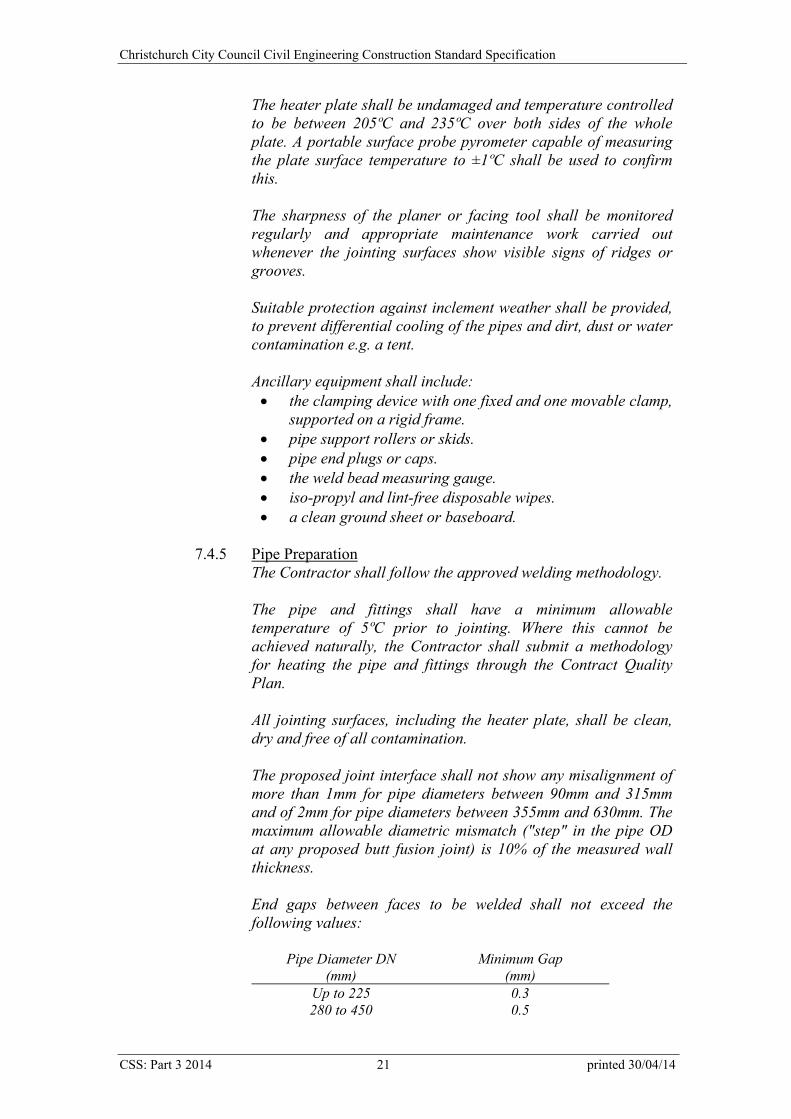
Christchurch City Council Civil Engineering Construction Standard Specification
The heater plate shall be undamaged and temperature controlled to be between 205ºC and 235ºC over both sides of the whole plate. A portable surface probe pyrometer capable of measuring the plate surface temperature to ±1ºC shall be used to confirm this. The sharpness of the planer or facing tool shall be monitored regularly and appropriate maintenance work carried out whenever the jointing surfaces show visible signs of ridges or grooves. Suitable protection against inclement weather shall be provided, to prevent differential cooling of the pipes and dirt, dust or water contamination e.g. a tent. Ancillary equipment shall include: the clamping device with one fixed and one movable clamp,
supported on a rigid frame. pipe support rollers or skids. pipe end plugs or caps. the weld bead measuring gauge. iso-propyl and lint-free disposable wipes. a clean ground sheet or baseboard.
7.4.5 Pipe Preparation
The Contractor shall follow the approved welding methodology. The pipe and fittings shall have a minimum allowable temperature of 5ºC prior to jointing. Where this cannot be achieved naturally, the Contractor shall submit a methodology for heating the pipe and fittings through the Contract Quality Plan. All jointing surfaces, including the heater plate, shall be clean, dry and free of all contamination. The proposed joint interface shall not show any misalignment of more than 1mm for pipe diameters between 90mm and 315mm and of 2mm for pipe diameters between 355mm and 630mm. The maximum allowable diametric mismatch ("step" in the pipe OD at any proposed butt fusion joint) is 10% of the measured wall thickness. End gaps between faces to be welded shall not exceed the following values:
Pipe Diameter DN (mm)
Minimum Gap (mm)
Up to 225 0.3 280 to 450 0.5
CSS: Part 3 2014 21 printed 30/04/14
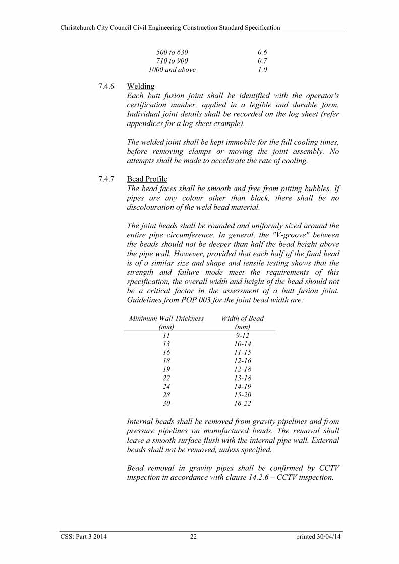
Christchurch City Council Civil Engineering Construction Standard Specification
500 to 630 0.6 710 to 900 0.7
1000 and above 1.0
7.4.6 Welding Each butt fusion joint shall be identified with the operator's certification number, applied in a legible and durable form. Individual joint details shall be recorded on the log sheet (refer appendices for a log sheet example). The welded joint shall be kept immobile for the full cooling times, before removing clamps or moving the joint assembly. No attempts shall be made to accelerate the rate of cooling.
7.4.7 Bead Profile The bead faces shall be smooth and free from pitting bubbles. If pipes are any colour other than black, there shall be no discolouration of the weld bead material. The joint beads shall be rounded and uniformly sized around the entire pipe circumference. In general, the "V-groove" between the beads should not be deeper than half the bead height above the pipe wall. However, provided that each half of the final bead is of a similar size and shape and tensile testing shows that the strength and failure mode meet the requirements of this specification, the overall width and height of the bead should not be a critical factor in the assessment of a butt fusion joint. Guidelines from POP 003 for the joint bead width are: Minimum Wall Thickness
(mm) Width of Bead
(mm) 11 9-12 13 10-14 16 11-15 18 12-16 19 12-18 22 13-18 24 14-19 28 15-20 30 16-22
Internal beads shall be removed from gravity pipelines and from pressure pipelines on manufactured bends. The removal shall leave a smooth surface flush with the internal pipe wall. External beads shall not be removed, unless specified. Bead removal in gravity pipes shall be confirmed by CCTV inspection in accordance with clause 14.2.6 – CCTV inspection.
CSS: Part 3 2014 22 printed 30/04/14
Christchurch City Council Civil Engineering Construction Standard Specification
7.4.8 Joint Failure during Handling and Installation If a joint fails during handling and installation, the Contractor shall inform the Engineer immediately. The Contractor shall provide the Engineer with the failed joint identification number and details of proposed actions to determine if the failed joint is an isolated incident or if it is a symptom of a more widespread problem, through the provision of a Non-Conformance Report. No further pipe installation shall take place until the corrective action is accepted.
7.5 Measurement of Works and Basis of Payment Jointing shall be included in the pipe installation rate.
8.0 PIPE INSTALLATION All pipes shall be laid in accordance with the relevant current code, as listed in clause 2.0 – Related Documents, and the manufacturer’s instructions. Pipes shall not be backfilled until the Engineer has had sufficient opportunity to obtain as-built measurements, in accordance with CSS: Part 1 - General. The Contractor shall ensure that as-built measurements have been taken before backfilling. Oval grid reinforced pipes shall be laid so that the lifting eye or the word “top” is uppermost. 8.1 Line and Level
Pipe inverts shall be laid to ±10mm of the design vertical alignment. Pipes shall be individually aligned to grade. Gravity pipes shall not be laid at a negative grade. Vacuum sewer pipes shall be laid within 0.05% of the design gradient. Pipe alignments shall be positioned horizontally within the greater of 50mm or 5% of the pipe diameter from the location specified. Under no circumstances shall the Contractor be permitted to locate or suspend centre lines from sight bars. An independent bar shall be used, placed as close to the ground as possible.
8.1.1 Lasers
Lasers shall: be self levelling within a range of ±5º. be robust and suitable for construction applications. be protected from the effects of vibration.
CSS: Part 3 2014 23 printed 30/04/14

Christchurch City Council Civil Engineering Construction Standard Specification
Self-levelling equipment shall be accurate to within +/-0.002% and shall be calibrated every 12 months. Lasers should have a warning indication if the system is off-grade by more than 1mm in 10 metres.
8.1.2 Use of Lasers Laser use shall comply with NZS 5821.2 “Plain language code of practice for the safe use of lasers in surveying, levelling and alignment”. Regular checks shall be carried out of the laser to ensure that: the light beam is on grade. the light beam is on line. the light beam is set at the correct level above the invert of
the pipe to be laid. Level checks shall be made against the site datum at each new manhole. If the laser beam is showing evidence of being affected by hot or cold air currents, the Contractor shall stop laying pipe and take all necessary steps to remedy the problem.
8.2 Cutting
Concrete pipes shall be cut with a stonemasons saw and exposed reinforcing coated with 5mm minimum depth of epoxy coating, applied strictly in accordance with the manufacturer's instructions.
8.3 Cleanliness
Internal pipe walls shall be kept clean and free of all dirt, rubbish and water. Spigots, sockets, rubber rings, etc, shall be thoroughly cleaned before jointing.
8.4 Leaks
The Contractor shall repair all leaks noted within the contract or defects liability period, including pipelines that have passed performance tests.
CSS: Part 3 2014 24 printed 30/04/14
Christchurch City Council Civil Engineering Construction Standard Specification
8.5 Pipe Protection Haunching materials shall be in accordance with SD 344, unless otherwise specified. 8.5.1 Haunching and Surround
Haunching shall be in accordance with SD 344. Haunching and surround shall be compacted to the greater of the manufacturer’s requirements or a minimum dry density of 2,050kg/m3 at any point on any haunching constructed of M/4: AP20 materials. Where the pipe is beneath a carriageway and with less than 1.5m cover, Drainage AP20 haunching shall be compacted to a Density Index of 70%. Otherwise it shall be compacted to a Density Index of 60%. Dry density ratio may be used as a compaction measure for CCC Drainage AP20 where the field dry density is to be 95% and 90% of the maximum dry density respectively. Haunching to underchannel pipes shall be laid to ensure that excavation for the carriageway adjacent to the pipeline does not allow the collapse of the haunching or remove support for the concrete capping and kerb and channel. Haunching and surround shall be thoroughly worked into place, particular care being taken to ensure that the material is thoroughly compacted under the full length of the pipe. Where the pipes are larger than 460mm diameter, material shall be compacted by a power vibrator. The foundation shall be lime stabilised where it would be subject to scouring. In liquefaction prone areas the Engineer may require the haunching and foundation to be protected by an approved geotextile complying with Appendix J of AS/NZS 2566.2 “Buried flexible pipelines – Installation”. Nuclear densometer use shall comply with CSS: Part 1 clause 29.5.1 – Compaction testing. The dry density shall be determined in accordance with NZS 4402.4.1.3 “New Zealand vibrating hammer compaction test”. The maximum dry density shall be determined in accordance with NZS 4402.4.1.1 “New Zealand Standard Compaction test”. The Density Index shall be determined in accordance with AS 1289.5.6.1 “Soil compaction and density tests - Compaction control test - Density index method for a cohesionless material”.
8.5.2 Concrete Capping Concrete capping to underchannel pipes shall be in accordance with SD 332. Concrete capping to underchannel piping shall be reinforced in commercial vehicle crossings only.
CSS: Part 3 2014 25 printed 30/04/14
Christchurch City Council Civil Engineering Construction Standard Specification
8.5.3 Concrete Surround
Concrete surround shall be in accordance with SD 342 except for underchannel pipes that shall be in accordance with SD 331. Concrete surround to underchannel piping shall be reinforced in commercial vehicle crossings only. PVC pipes shall not be concrete surrounded. Flotation of the pipe during the placement of concrete surround shall be prevented.
8.5.4 Concrete Protection Slab to PVC Pipes Where cover over PVC pipes is less than the minimum as stated in clause 8.7 – Flexible Pipes, including temporarily under construction traffic, a concrete protection slab shall be constructed in accordance with SD 342.
8.5.5 Joint Formers Contraction joints shall be formed in concrete capping and surround at pipe joints at a maximum spacing of 10m. Joints can be formed by placing a spacer of soft board or equivalent in the concrete at the pipe joint.
8.5.6 Geotextiles Geotextile supply and installation shall be in accordance with AS/NZS 2566.2 “Buried flexible pipelines – Installation”. Where specified, geotextile wrapping of joints shall extend at least 0.5m each side of the joint. The geotextile shall be snugly secured around the pipe with cable ties or similar.
8.5.7 Pipe foundations
Where soft ground foundations are specified for part of a manhole to manhole length, the foundation shall extend from the pipe joint before the length to be supported to the pipe joint past the end of the length to be supported.
8.6 Pipe Installation on Hillsides
8.6.1 Treatment of Under-runners
The Contractor shall notify the Engineer of any under–runners, erosion cavities or tunnel gullies encountered during excavation. The Engineer shall advise on under-runner treatment.
8.6.2 Water stops Water stops shall be constructed in accordance with SD 347 or as specified.
8.7 Flexible Pipes
CSS: Part 3 2014 26 printed 30/04/14
Christchurch City Council Civil Engineering Construction Standard Specification
Unprotected PVC and polyethylene pipes shall have minimum cover of 750mm in roads and streets, 600mm in driveways and similar areas subject to traffic, and 500mm in footpaths, gardens and open country. Stormwater laterals that discharge to the kerb shall be laid with the maximum cover achievable, up to these requirements. PVC piping shall be protected with 6mm thickness of Denso tape or 250 microns polyethylene film or equivalent where adjacent to concrete.
8.8 Pressure Pipelines Pressure pipelines shall be haunched and laid in accordance with SD 344 and clause 8.5 – Pipe Protection. The full length of the pipe barrel shall bear continuously upon the haunching. Pressure pipes shall have a maximum cover of 1.5m unless specified otherwise. The bearing capacity of the side support material, for curved pipelines with approved deflection joints, shall be checked to confirm it exceeds the specified capacity. Mechanical couplers shall only be used on polyethylene pressure pipe under 125mm OD. 8.8.1 Thrust blocks
Concrete thrust blocks shall be constructed either in accordance with SD 346 or as designed in the locations specified. Thrust blocks must have developed adequate compressive strength before the pipeline is pressure tested. The thrust block dimensions specified are the minimum for installation at the specified pressure. Thrust blocks shall be poured against natural ground. If this is not possible, approved material shall be carefully backfilled and compacted in layers around and behind the thrust block. The bearing capacity of the natural or filled ground shall be checked, to ensure it complies with the design capacity, before construction. Proof of this testing shall be provided through the Inspection and Test Plan in the Contract Quality Plan.
8.8.2 Anchor blocks Anchor blocks shall comply with CSS: Part 4 clause 12.6 – Gradient Anchor Blocks.
8.8.3 Valves and surface covers Valves shall be installed in accordance with CSS: Part 4 clause 12.2.1 – Valves. Surface boxes shall be installed in accordance with CSS: Part 4 clause 12.2.3 - Surface boxes and SD 412.
CSS: Part 3 2014 27 printed 30/04/14
Christchurch City Council Civil Engineering Construction Standard Specification
Triangular valve spindle caps complying with SD 382 shall be installed on all wastewater pressure valves within legal road. Roadmarking shall be undertaken in accordance with CSS: Part 4 clause 19.0 – Location Marking of Fire Hydrants and Sluice Valves. Pressure sewer system surface boxes shall be painted white.
8.9 Subsoil Drains
Subsoil drains shall be laid in accordance with SD 377. Subsoil pipes shall have minimum cover of 750mm within the roadway, 600mm in driveways and rights of way, and 500mm in other applications unless otherwise specified.
8.10 Pipelaying at Structures If entry openings are required in a precast or existing manhole and no knock out panels have been left, the openings shall be made using a diamond-cutting blade or hole saw. Under no circumstances shall a hammer or impact tool be used.
8.10.1 Yield Joints
Yield joints shall be formed in accordance with SD 341. Yield joints at sumps shall be constructed with one short pipe and two yield joints. Jointing of cut pipes to form a closure shall be avoided if possible. If such jointing is necessary, it shall be done with a gibault joint or with purpose built fittings provided by the pipe manufacturer. Any adjustment of the length of the lay necessary to obtain yield joints at the structure shall be done to the approval of the Engineer.
8.10.2 Underchannel Piping Yield joints shall be constructed on concrete capped underchannel piping at all sumps.
8.10.3 Starters/Finishers
Structures shall not leak at the interface with the starter or finisher.
8.10.4 Polyethylene Connection to Manholes Connections to concrete access chambers shall be in accordance with SD 341/3. Plastic Chambers shall have an approved purpose made connection.
CSS: Part 3 2014 28 printed 30/04/14
Christchurch City Council Civil Engineering Construction Standard Specification
8.10.5 Long Socket Connectors Flexible joints shall be formed in accordance with SD 341/4. No laterals shall be connected to the first pipe length laid into the long socket connecter i.e. within 4.0m of the manhole. Ensure benching does not prevent the internal pipe moving into the manhole. The benching should be to a larger diameter than the long socket.
8.10.6 Collector sewers Collector sewers shall enter both the upstream and downstream manholes when laid directly over the sewer main. Caps are not required on the upstream end of the collector sewer. Drop structures are not required on the outlet where there is less than 1.0m between the invert of the collector sewer and the soffit of the sewer main.
8.11 Measurement of Works and Basis of Payment
8.11.1 Pipe Installation
Payment shall be per lineal metre, to the nearest 0.1m, based on the horizontal length of pipe installed. Lengths shall be measured from the centreline of the on-line structure or from the termination point of the pipeline e.g. headwall, inlet. All structures shall be regarded as “extra over” the pipe installation rate for payment purposes. Each type of pipe shall be measured and paid separately. Pipe installation shall include excavation, work around services, support of existing services under 40mm diameter, supplying and laying, haunching, jointing, geotextile wrapping to joints, pipe testing, backfill placing, compaction to subgrade level and compliance testing in accordance with clause 15.4 – Quality Assurance. The supply of imported backfill is scheduled separately.
8.11.2 Pipe Protection and Haunching Haunching shall be included in the rate for pipe installation. Where haunching is scheduled separately, it shall be paid per lineal metre, to the nearest 0.1m. Haunching shall include the supply and placing of all foundations, haunching and pipe surround materials. This includes to 150mm above the barrel for ceramic and flexible pipes in accordance with SD 344. Concrete capping, surround and protection slabs are paid per lineal metre, to the nearest 0.1m, and shall include joint formers.
CSS: Part 3 2014 29 printed 30/04/14
Christchurch City Council Civil Engineering Construction Standard Specification
8.11.3 Geotextiles Geotextile surrounds, cover over haunching materials and raft foundations shall be paid per lineal metre, to the nearest 0.1m, based on the horizontal length of pipe treated. Excavation, pipe installation, work around services and haunching are included in the rate for pipe installation. Geotextile wrapping to pipe joints shall be included in the pipe installation rate. Geotextiles shall include supply, installation, lacing or fixing and testing. No extra payment will be made for laps or returns. Soft ground geotextiles shall be paid per square metre of geotextile laid. Raft foundations include geogrid, geotextile and GC65-40.
8.11.4 Treatment of Under-runners The treatment of under-runners shall be measured by the volume of fill placed, to the nearest 0.1m3. This rate shall include any labour and equipment required to place this material.
8.11.5 Water stops Payment shall be per item. Where water stops are modified, their cost will be adjusted in accordance with the rates provided.
8.11.6 Thrust blocks Payment shall be per item. This shall include confirming through site testing the capacity of the ground on which the thrust block bears. Where thrust blocks are modified, their cost will be adjusted in accordance with the rates provided.
8.11.7 Subsoil Drains Subsoil drains shall be paid in accordance with clause 8.11.1 – Pipe installation. Subsoil drains shall include the supply and placement of geotextiles.
8.11.8 Pipelaying at Structures Pipelaying at structures shall be included in the pipe installation rate. This item shall include all short pipes and special connectors required.
9.0 POLYETHYLENE PIPE INSTALLATION All pipes shall be transported, haunched and installed in accordance with clause 8.0 – Pipe Installation, AS/NZS 2033 “Installation of polyethylene pipe systems” and the pipe manufacturer’s recommendations. Pipe shall not be bent to a radius less than 35 times the pipe OD. Pinching or squashing of polyethylene pipe to facilitate the installation of fittings is not permitted.
CSS: Part 3 2014 30 printed 30/04/14
Christchurch City Council Civil Engineering Construction Standard Specification
9.1 Pipe Installation by Trenchless Technology Gouging or notching of the pipe shall not exceed 10% of the pipe wall thickness for pressure pipe and 20% of the pipe wall thickness for gravity pipe. Pipe shall not be bent to a radius less than 35 times the pipe OD. The specified allowable load on the pipe shall not be exceeded during pulling. Where gouging or notching exceeds the above limits or if buckling of the pipe occurs, that length of pipe shall be removed and a new section welded in at the nearest join. The Contractor shall overtow the pipe by one lineal metre for each length of pulled pipe that is the greater of one manhole length or 200m. The excess pipe length shall be supplied to the Engineer for a visual inspection. 9.1.1 Polyethylene Pipe Installation by Pipebursting
Where the polyethylene pipe is to replace a live pipeline, the line to be burst shall be inspected by CCTV to locate all laterals and to check for any obstructions. Live laterals shall be confirmed through the use of dye.
9.1.2 Polyethylene Pipe Installation by Slip Lining The host pipe shall be cleaned to provide a clear pipe diameter that passes the new polyethylene pipe without gouging or notching the pipe. Disposal of the cleanings shall be carried out in accordance with CSS: Part 1 - General. The Contractor shall not detrimentally affect the host pipe when cleaning it. The most effective method of cleaning steel pipes in Christchurch is through physical scraping. Prior to any attempt to pull in the new polyethylene pipe a plug, no less than the diameter of the new pipe, shall be passed through the host pipe to ensure there is sufficient clearance.
9.1.3 Polyethylene Pipe Installation by Directional Drilling The constructed pipe alignment shall not vary more than 100mm horizontally from the design alignment and the tolerance on the vertical alignment shall not exceed the specified amount except where the grade of the pipe is specified, in which case it shall be ±5mm from the design grade. Cover to pipes of 100mm diameter or greater shall not be less than 750mm, unless approved by the Engineer. Cover to pipes smaller than 100mm in carriageways or where likely to be
CSS: Part 3 2014 31 printed 30/04/14
Christchurch City Council Civil Engineering Construction Standard Specification
crossed by vehicles shall be 750mm and elsewhere cover shall be 450mm. The maximum cover shall be 2.0m, unless approved by the Engineer. All liquid waste shall be disposed of in accordance with CSS: Part 1 - General. Clearances to services shall be in accordance with the particular Utility Operator’s requirements. The Contractor shall be liable for damages to any underground services. The Contractor shall accurately monitor the position of the drilling head to achieve the above requirements.
9.2 Access Pits
Minimum pit length (m) for pipe diameter (mm) Pit Depth 50 63 75 90 110 125 160 180 200 250
0.6 2.0 2.2 2.4 2.7 3.0 3.2 3.6 3.8 4.2 4.6 0.8 2.2 2.5 2.8 3.1 3.4 3.7 4.2 4.4 4.8 5.2 1.2 2.6 3.0 3.3 3.7 4.2 4.4 5.0 5.4 5.8 6.4 1.6 2.9 3.4 3.8 4.2 4.8 5..0 5.8 6.1 6.6 7.4 2.0 3.2 3.7 4.1 4.6 5.2 5.6 6.4 6.8 7.2 8.2 2.4 3.3 3.9 4.4 4.9 5.6 6.0 7.0 7.4 8.0 8.8 2.8 3.4 4.1 4.6 5.2 6.0 6.4 7.4 7.9 8.4 9.6 3.2 3.5 4.2 4.8 5.5 6.2 6.8 7.8 8.4 9.0 10.0 3.6 3.5 4.3 5.0 5.7 6.6 7.1 8.2 8.8 9.4 10.6
Assumptions:
a) New pipe is parallel with the road at the start of the pit and parallel (and in line) with the old pipe at the end of the pit. If this does not apply, calculate the minimum pit length from (b).
b) Table is based on a minimum PE pipe bend radius of 35 times pipe OD.
Pipes shall be haunched through any pits in accordance with clause 8.0 – Pipe Installation.
CSS: Part 3 2014 32 printed 30/04/14
Christchurch City Council Civil Engineering Construction Standard Specification
9.3 Pressure Sewer Systems 90 degree deflections on pressure laterals shall be constructed using two individual bends of 45 degrees.
9.4 Measurement of Works and Basis of Payment Where additional pipe is pulled to provide a sample for visual inspection of notching and gouging, the Contractor will be paid for a one-metre sample only.
9.4.1 Pipe Installation in Open Trenches
Payment shall be per lineal metre, to the nearest 0.1m, including pits and welds. Pipe installation shall include excavation, work around existing services, supplying, jointing, laying, haunching, provision of samples and testing, backfill placing and compaction. The supply of imported backfill is scheduled separately.
9.4.2 Pipe Installation by Pipebursting Payment for pipe installation shall be per lineal metre, to the nearest 0.1m, including pits and jointing. Pipe installation shall include location of services, pipe bursting, pulling the pipe, haunching and backfilling in pits, including the supply of all materials, provision of samples and testing.
9.4.3 Pipe Installation by Slip Lining
Payment for pipe installation shall be per lineal metre, to the nearest 0.1m, including pits and jointing. Pipe installation shall include cleaning the host pipe and checking for clearances, pulling the pipe, haunching and backfilling in pits, including the supply of all materials, provision of samples and testing.
Special anchor blocks are scheduled separately.
9.4.4 Pipe Installation by Directional Drilling Payment for pipe installation shall be per lineal metre, to the nearest 0.1m, including pits and jointing. Pipe installation shall include determining the alignment, drilling, haunching and backfilling in pits, including the supply of all materials, provision of samples and testing.
CSS: Part 3 2014 33 printed 30/04/14
Christchurch City Council Civil Engineering Construction Standard Specification
10.0 JUNCTIONS AND RISERS
10.1 Junctions PVC junctions shall be formed with factory moulded junction fittings and in accordance with SD 363. PVC side junctions, inspection bends and ramped risers shall be metal haunched and surrounded. All junctions except for risers shall be fitted with their permanent seal before testing.
10.2 Risers Risers shall be constructed where the main is greater than 1.8m below the finished road level, unless ordered otherwise by the Engineer. This elevation may be altered to provide cover to the lateral at the road boundary as specified in clause 11.0 - Laterals. It may also be altered due to the presence of other services, the location of the water table, land levels and convenience of connection.
10.3 End Plugging The ends of all junctions and riser pipes, if not brought into immediate use, shall be plugged in accordance with SD 363.
10.4 Polyethylene Junctions and Adaptors
Fittings shall be approved and factory made. Jointing shall be in accordance with clause 7.0 - Jointing. Junctions shall be constructed in accordance with SD 364. Cut edges shall be left smooth. The Contractor shall horizontally over-excavate each junction hole by 200mm to allow the new line to be properly haunched. The Contractor shall not backfill the trench until the Engineer has inspected the connections.
10.5 Measurement of Works and Basis of Payment 10.5.1 Junctions
Junctions shall be paid per item and shall include all costs over normal pipe installation, concrete surround, short pipes and end plugging. Junctions shall also include the replacement of up to 1.0 metre of each sewer lateral. Any subsequent length of renewal shall be paid under laterals. The position and number of junctions specified is a guide only, and the actual position, number, type, and setting will be determined on site.
CSS: Part 3 2014 34 printed 30/04/14
Christchurch City Council Civil Engineering Construction Standard Specification
10.5.2 Risers Payment shall be per metre, to the nearest 0.1m, measured from the face of the junction socket. Risers shall include the replacement of up to 1.0 metre of each sewer lateral. Any subsequent length of renewal shall be paid under laterals.
11.0 LATERALS
Laterals shall be constructed in accordance with clause 8.0 – Pipe Installation. The existing main and laterals shall be kept in continuous operation until connected to the proposed piping. The Contractor shall note that the exact location of some laterals is unknown. The Contractor shall verify the reconnection to the new main of all live laterals. This may require the isolation of sections of the new main and flushing water down drain entries, gully traps or toilets to ensure each house is connected. 11.1 Laterals in Close Proximity to Trees
All adaptor joints in laterals shall be a minimum of 3 metres from the trunk of any tree. Laterals that are located beneath the area occupied by the canopy of any tree or within 3 metres of its trunk shall be renewed using an approved trenchless method of installation.
11.2 Sewer Lateral Cover at Lot Boundary The invert level of the sewer lateral at the lot boundary should be a minimum of 1100mm below the finished surface or at a depth sufficient to adequately serve the whole lot. The cover over the barrel of the sewer lateral at the kerb should not be less than 800mm.
11.3 End Capping and Marking Where laterals are not immediately connected to property drains, the blank end shall have a watertight end plug fitted. The blank end of the pipe shall be marked with a 100mm x 25mm stake, installed prior to backfilling from the pipe end vertically to 150mm below design finished level. The timber stake will facilitate as-built measurements and location of the lateral for later connections.
CSS: Part 3 2014 35 printed 30/04/14
Christchurch City Council Civil Engineering Construction Standard Specification
11.4 Lateral/Mainline Sequence Where the ground is soft and liable to settlement or a traffic hazard will result, the Contractor should lay laterals after the main pipeline trench has been backfilled and compacted.
11.5 Fluming of Disconnected Laterals
To eliminate uncontrolled sewerage discharge into any excavation or pit, the main and/or lateral in each excavation must be temporarily flumed within two hours of severing. The Engineer shall approve the Contractor’s proposed method prior to use.
11.6 Laterals into Polyethylene Pipe
Laterals shall be constructed in accordance with clause 9.0 – Polyethylene Pipe Installation. The Contractor shall overtow the pipe by one lineal metre at one of the longer laterals. The excess pipe length shall be supplied to the Engineer for a visual inspection.
11.7 Connecting to Existing Laterals
PVC-u adaptors shall be installed over rubber rings onto earthenware laterals. The epoxy shall be screed off at a 45 degree angle. New PVC-u laterals shall be connected to existing concrete laterals using stepped gibaults only. Gibaults shall be wrapped as specified in clause 7.1 – Mechanical Jointing.
11.8 Measurement of Works and Basis of Payment Payment shall be per lineal metre, to the nearest 0.1m. Laterals shall be measured from the face of the junction socket. Laterals shall include all those items in pipe installation under clause 8.0 – Pipe Installation, fluming and the verification that laterals are live and have been connected, fittings and restoration. The supply of imported backfill is scheduled separately. 11.8.1 Laterals Requiring Structural Maintenance
Existing laterals requiring structural maintenance shall be re-laid as ordered and payment will be made at the rate for installing laterals.
11.8.2 Laterals into Polyethylene Pipe Laterals shall also include all those items in polyethylene pipe installation under clause 9.0 – Polyethylene Pipe Installation.
CSS: Part 3 2014 36 printed 30/04/14
Christchurch City Council Civil Engineering Construction Standard Specification
12.0 STRUCTURES Structures shall be positioned within 50mm horizontally of the location specified. All structures shall be watertight. 12.1 Reference Documents
A copy of NZS 3109 “Concrete construction” shall be kept on site. The below clause references shall extend and modify NZS 3109 as stated. ‘Recommended practice’, as stated in NZS 3109, clause 1.2.1, shall be adhered to unless specified below. The "Construction Reviewer", defined in NZS 3109, clause 2, shall mean the Engineer.
12.2 Quality Assurance 12.2.1 Contract Quality Plan
The Contractor’s project quality system should encompass all aspects of the concrete construction, but be not necessarily limited to: Concrete assessment (submit details in the Inspection and
Test Schedule with tender) to NZS 3109. Inspection prior to placement of concrete (Concrete Pour
Card Records). Reinforcement compliance records (e.g. Certificates of
origin or Certification by a registered laboratory). Details of Concrete Supply to meet the requirements of
NZS 3109. Proposed concrete mix designs. Daily Concrete Batch Records (including water content and
moisture content of aggregates). Tolerance checks of critical items (e.g. Checking cast-in
weld plates). Monitoring of off-site precast manufacture.
The Contractor shall supply evidence of production quality standards to the Engineer in advance of construction by provision of the Certificate of Audit, required by NZS 3104, clause 2.16 – Quality Audit. Details of the proposed methods and frequency of such activities, and the reporting of these, shall be set out in the Contractor’s Contract Quality Plan.
12.2.2 Personnel The Contractor’s Quality Controller shall complete and sign a written quality control checksheet for each off-site or on-site concrete pour, prior to any concrete being poured, to confirm that
CSS: Part 3 2014 37 printed 30/04/14
Christchurch City Council Civil Engineering Construction Standard Specification
all work complies with the Contract documents. A typical checksheet is in Appendix 1. The Contractor shall be represented on site by a competent leading hand (reinforcing), while steel is being placed. During pouring, the Contractor shall have appropriately skilled personnel on call to identify and correct any damaged or displaced reinforcing.
12.3 Reinforcement All reinforcement shall be micro-alloy steel manufactured by Pacific Steel Limited. ‘Reidbars’ shall be supplied by Reid Engineering Systems Limited. The Contractor shall prepare reinforcement schedules from the contract drawings. Reinforcing bar shall be notated on the drawings as follows, unless noted otherwise:
R – Plain Grade 300; D – Deformed Grade 300E; RH – Plain Grade 500E; DH – Deformed Grade 500E; RB – Reid Bar Grade 500E.
Further to NZS 3109, clause 3.3.4, bending of reinforcement shall conform to the minimum bend radii given in NZS 3101. Any reinforcement that does not comply shall be rejected and replaced. Further to NZS 3109, clause 3.3.8, re-bending of Grade 500E reinforcement shall not be allowed. Any reinforcement that has been re-bent shall be rejected and replaced. Further to NZS 3109, clause 3.4, steel reinforcement shall be stored on supports clear of the ground and shall be protected from sea spray, on delivery to site. Further to NZS 3109, clause 3.5.1, where top steel in slabs is supported from bottom steel, a plastic spacer shall be placed beneath the bottom steel immediately under the top steel support. Further to NZS 3109, clause 3.9, under no circumstances shall reinforcement be displaced from the positions shown on the drawings for the purpose of accommodating conduits or service pipes etc. of any description, without the written permission of, and to the details specified by, the Engineer Further to NZS 3109, clause 3.7.1, lapping bars necessitates the Engineer’s approval.
CSS: Part 3 2014 38 printed 30/04/14
Christchurch City Council Civil Engineering Construction Standard Specification
Splices in adjacent bars shall be staggered by at least 600mm. Bars with kinks or bends not shown on the drawings shall not be used. Further to NZS 3109, clause 3.7.2, welding of reinforcement necessitates the Engineer’s approval. No site welding shall be permitted under any circumstances. If permitted, welding shall comply with AS/NZS 1554.3 “Structural steel welding - Welding of reinforcing steel”. Grade 500 reinforcement shall not be welded without the development of a specific shop welding procedure. The Engineer shall approve welders and shall inspect welds, where specified.
12.4 Formwork All concrete exposed in the finished structure, and in particular that which is in frequently used public spaces, shall have the formwork and spacer layout approved by the Engineer prior to construction commencing. Further to NZS 3109, clause 5.1.1, all concrete shall be placed in formwork unless specified or approved otherwise. Formwork shall be inspected and levels checked immediately preceding the placing of reinforcement and any bulging, warping or lack of fit shall be remedied. The formwork for each section of concrete placement shall be completely constructed before concreting of that section is commenced. Steel formwork shall have all joints welded and ground smooth and flush. All internal corners shall be formed by folding the steel, not by butting. Further to NZS 3109, clause 5.1.2, concrete work that is misshapen or in any other way defective due to the inadequacy of the formwork, shall be rejected, removed and replaced or the defect remedied as directed by the Engineer, at the Contractor’s cost. Further to NZS 3109, clause 5.1.4, all insertions shall have a slight bevel to ensure easy removal without damage to the concrete. Further to NZS 3109, clause 5.1.6, before the reinforcement is placed, the interior surfaces of forms shall be treated with a release agent to prevent adhesion of mortar. Release agents shall be of a non-staining type applied in a thin film. 12.4.1 Construction Requiring Support From Other Permanent Works
Further to NZS 3109, clause 5.1.8, at least ten Working Days prior to the commencement of construction requiring support, the
CSS: Part 3 2014 39 printed 30/04/14
Christchurch City Council Civil Engineering Construction Standard Specification
Contractor shall supply to the Engineer the following information. Details of scheduled removal of props or loading of support
elements, including age of various levels of construction at critical stages.
Calculations or a Producer Statement from a Chartered Engineer, demonstrating that the requirements of this clause are satisfied.
Details of any concrete strength testing, additional to clause 12.17 – Compliance Testing of this part, to demonstrate that adequate strength is obtained prior to removal of props.
In providing support to construction from a previously constructed structure, the Contractor shall plan the removal of propping such that stresses and deflections are not excessive as follows: Construction Loads The construction loads imposed on a structure of age 28 days or more shall be such that the strength requirements do not exceed those induced by the design loading, unless it is demonstrated by calculation that the strength requirements are within the capacity of the supporting structure. Where the structure is less than 28 days old, the allowable loads shall be appropriately reduced. The Contractor is warned that leaving props in place may in some cases lead to an unacceptable accumulation of stresses in lower construction. Deflections Where construction loads on a structure are such that strength requirements are greater than those due to the design loading, or where a structure shall be loaded at an age less than 28 days, the Contractor shall demonstrate that calculated final deflections (following removal of construction loads and application of design loads) are either less than the calculated deflections which would be caused by the application of the design loading, or within acceptable limits as defined by the Engineer. Such calculations shall take into account, where appropriate, non-recoverable deflections due to creep of young concrete.
Further to NZS 3109, clause 5.3.2, the straightness over a 3.0m straightedge shall not disclose out-of-plane exceeding 1mm. Notwithstanding the tolerances specified, no tolerances shall be permitted to accumulate to such an extent that the accurate placing of precast units
CSS: Part 3 2014 40 printed 30/04/14
Christchurch City Council Civil Engineering Construction Standard Specification
to meet the tolerances shown in the Drawings, fixings, equipment, reinforcement, etc., is jeopardised. Where an error requires correction between one bay and the next or between one level and the next, the Engineer shall approve such corrections in advance. Further to NZS 3109, clause 5.4, the following minimum stripping times shall apply for the following classes of work:
Class of Work Portland
Cement Rapid Hardening Portland Cement
Removal of formwork from walls and risers.
48 hours 24 hours
Removal of formwork from haunching, junctions, etc.
24 hours 18 hours
Removal of props from manhole and flush tank slabs, culverts, etc.
21 days 7 days
All formwork shall be removed before backfilling. All external angles in exposed members shall be protected against injury after stripping. Once the formwork has been stripped all tie holes, honeycombing and excessive blowholes shall be filled and sufficiently compacted with mortar composed of one part of cement to two parts of clean plastering sand. Care shall be taken to apply sufficient mortar to fill the voids, as it is not intended that the whole surface be coated. After the mortar has dried, but not set, the mortared surfaces and all abrupt changes, as defined in NZS 3114 Figure 1, shall be rubbed with a coarse carborundum stone to produce a smooth surface free from honeycombing, excessive blowholes and sharp abrupt changes.
12.5 Precast Concrete Shop Drawings The Contractor shall produce and provide, if specified, fully detailed shop drawings for all precast concrete. These drawings shall be sufficient to enable fabrication of the structures to the dimensions, shapes and standards specified. The Engineer shall receive the shop drawings at least 5 working days before fabrication. The Contractor shall ensure that:
shop drawings are co-ordinated with the requirements of all other trades and other trade’s shop details, in particular electrical, plumbing, drainage and steelwork.
all necessary site measurement and checking has been undertaken. the shop drawings are co-ordinated with all Contract requirements.
The Contractor shall advise the Engineer of any errors, omissions or conflicts found in the Drawings during the shop drawing preparation.
CSS: Part 3 2014 41 printed 30/04/14
Christchurch City Council Civil Engineering Construction Standard Specification
The Engineer shall review the shop drawings for design concept and general arrangement only. Dimensional accuracy remains the Contractor’s responsibility. Drawings shall be provided to the Engineer 10 working days prior to manufacture of the precast units.
12.6 Embedded Items
Further to NZS 3109, clause 5.5, the Contractor shall check the requirements of other trades and shall be wholly responsible for the accuracy of locating all such items. All embedded items shall be accurately set and supported in place until the concrete has set. Where pipes, castings, or conduits pass through a wall or floor, the Contractor shall place such pipes or castings in the form before placing the concrete. The Contractor may alternatively build boxes in the forms, where specified or as approved by the Engineer. To withstand water pressure and ensure watertightness around openings, the boxes or cores shall be provided with continuous keyways and shall have a slight flare to facilitate concreting in walls and the escape of air entrained during concreting. Where possible, boxed holes shall be orientated with an apex over the pipe. The face between the boxed opening and void to be concreted shall be treated as a cold joint. The pipes, castings or conduits shall be concreted in place under a concrete head of at least 100mm. The concrete shall be worked into place to completely fill the space between the pipes, castings or conduits and the sides of the openings to obtain the same watertightness as through the wall itself. Pipes less than 75mm diameter in cored holes shall be fixed in place as specified. Where the floor of the structure is poured separately, the concrete in the vicinity of the embedded pipe shall be kept sufficiently low to ensure the gap between pipe and floor is a minimum of 50mm when the pipe is laid. In water retaining structures the minimum cover to embedded tie bolts shall be 40mm. Tie boltholes shall be filled with dry pack mortar or an approved equivalent, within two days of the removal of formwork. 12.6.1 Knock Out Panels
The Contractor shall make provision for future pipelines by forming 80mm thick square panels at the required levels, where specified or directed by the Engineer. The panels shall be formed by boxing out 150mm thick recesses on the outer side of the wall. Unused knockout panels shall be filled with concrete to the structure’s full wall thickness.
CSS: Part 3 2014 42 printed 30/04/14
Christchurch City Council Civil Engineering Construction Standard Specification
12.7 Construction Joints Further to NZS 3109, clause 5.6.1, where construction joints in slabs are not detailed, the Contractor shall ascertain the requirements of the Engineer before commencing. Walls may be poured in lifts exceeding 3000mm provided that the Contractor can demonstrate to the Engineer his ability to do so properly and consistently. Further to NZS 3109, clause 5.6.2.3, the Engineer reserves the right to nominate the method of repair, if edges at construction joints are damaged. Further to NZS 3109, clause 5.6.3, all construction joints shall be prepared and constructed to meet the requirements for 'Type B' construction joints, unless specified otherwise. The Contractor shall take special care at all construction joints to ensure that no joint will be a source of future weakness or leakage and that the specified surface finish is obtained either side of the joint. Approved water stops shall be used where specified or required by the Engineer. This is likely to be where there may be a head of water across the joint. In general, construction joints shall be perpendicular to the principal lines of stress. Construction joints across embedded pipes and lower than half pipe level should be avoided as a “V” is created between the concrete and pipe and it is difficult to get a proper seal in this section of the joint when the next lift is poured. Vertical construction joints shall not be permitted except where unavoidable and approved. Horizontal joints shall be evenly spaced, horizontal and continuous round any structure unless otherwise specified. The joint surface shall be treated within 24 hours of casting. Concrete shall not be placed against a construction joint face within 24 hours of an earlier placement. The Engineer shall approve any alternative joint surface preparation.
12.8 Supply of Concrete Further to NZS 3109, clause 6.1, no calcium chloride accelerator or similar chloride-containing admixture shall be added to any mix. Further to NZS 3109, clause 6.2, all concrete shall be Normal (N), with sufficient cement quantity to ensure satisfactory finish and durability. The nominal maximum aggregate size shall be 19mm. The water content shall not exceed 170 kg/m3.
CSS: Part 3 2014 43 printed 30/04/14
Christchurch City Council Civil Engineering Construction Standard Specification
Where specified, waterproof concrete shall contain XYPEX Admix C-1000 NF waterproofing admixture in accordance with the manufacturer’s specifications. If concrete does not comply with the slump specification on site, the Contractor may add superplasticiser to bring the concrete up to the specified slump. In all cases, the mix shall have been designed to be tolerant to this on-site modification. Full records of the addition of superplasticiser on site shall be kept on the delivery docket and on the plant batching records, including minimum mixing time after the addition of the superplasticiser. Further to NZS 3109, clause 6.3, the specified strengths are shown in the Drawings, but generally 10 MPa for site concrete, 50 MPa for piles, 40 MPa for foundation elements, 30 MPa for precast and in-situ walls and floor slabs and 20 MPa for footpaths.
12.9 Concrete Placing, Finishing and Curing The Engineer shall be notified and given a reasonable opportunity (a minimum of 24 hours) to inspect formwork, reinforcement and construction joints before pouring commences. Concrete that has partially hardened or has been contaminated by foreign materials shall not be deposited in the works. Retempered concrete shall not be used in the works. Further to NZS 3109, clause 7.1, concrete shall not be pumped without the Engineer’s prior approval. If approval is given, the concrete mix shall not be adjusted but the specified slump may be altered with the addition of superplasticisers. The Engineer requires notification in writing at least five working days before placement for approval. Further to NZS 3109, clause 7.2, concrete shall not be placed when the outdoor shade temperature exceeds 25ºC and no concrete shall be placed in water without the Engineer’s approval. If approved, the mix shall be adjusted and the work carried out as required by the Engineer. Concrete shall not be exposed to rain or sea spray during mixing, transport or placing or until it has set. Further to NZS 3109, clause 7.4, concrete shall be deposited as near as practicable to its final position. It shall not be dropped from a height in excess of 2m except with the prior permission of the Engineer, nor shall it be dumped away from its final position and worked along the forms. Except at permitted construction joints, concrete in each section of the work shall be placed in a continuous operation such that new concrete is constantly being placed against unset concrete to produce a monolithic mass.
CSS: Part 3 2014 44 printed 30/04/14
Christchurch City Council Civil Engineering Construction Standard Specification
All barrow runs, chute runs, pipelines, walkways and any other means of conveying concrete shall be adequately supported by independent means directly from the formwork and in no case shall the means of conveying the concrete be supported from or allowed to displace the reinforcement. The Contractor shall organise the delivery of concrete in such quantities as can be effectively handled by the labour and equipment available. The Engineer may at his discretion order the Contractor to provide additional equipment or men to assist in placing concrete and/or alter the method of placing. Further to NZS 3109, clause 7.7 and unless specified otherwise, the required finish shall be:
F5 for precast units and all other visible concrete, except as below F4 for in-situ concrete where surfaces are not visible, except as
below F3 for interiors of manholes, flush tanks and culverts U3 for slabs, except as below U5 for footpaths and bridge deck surfaces U1 for site concrete.
Set concrete shall not be cut, hacked or cored unless specific approval is obtained from the Engineer. For concrete at all surfaces (except floors) which will be visible on completion of the works, the minimum cement content shall be 350 kg/m3 mixed concrete and the maximum water cement ratio shall be 0.40. The Contractor shall allow for supplying a greater cement content than this should it be necessary to achieve the finish specified. Further to NZS 3109, clause 7.8, the Contractor shall take adequate steps to prevent surface evaporation of mix water, without increasing the water content of the concrete. These measures may include the provision of windbreaks or the application of a fine mist spray during concreting operations or any other measure approved by the Engineer. Traffic shall be kept off all structures until they have achieved the specified strength. Care shall be taken that no shock or vibration reaches concrete after setting until it is at least 3 days old, and that any starters projecting from green concrete are not shaken or disturbed. Concrete in which the reinforcement has been displaced shall be declared defective and shall be demolished.
CSS: Part 3 2014 45 printed 30/04/14

Christchurch City Council Civil Engineering Construction Standard Specification
Further to NZS 3109, clause 7.8.2, all flat slab work shall be wet cured by flooding or continually sprinkling for 24 hours after concrete finishing. After 24 hours, the surface shall be dried by squeegee for the immediate application of a 90% efficiency-curing compound, in accordance with the manufacturer’s instructions. The Contractor shall ensure the curing compound proposed is compatible with the subsequent floor covering or paint finish. Further to NZS 3109, clause 7.8.3, all vertical work, such as columns and walls, shall be cured by either leaving enclosed with formwork or tightly wrapping with polythene for at least 7 days after pouring. 12.9.1 Precast Concrete
Each unit shall be cast in one continuous pour, and shall be properly cured as soon as practicable after casting. Curing shall be by steam, wrapping in polythene or other method approved by the Engineer. Finished units shall be crack free.
12.9.2 Slabs Slab surfaces shall be finished to a hard, smooth, polished finish which does not vary more than 5mm from a 3 metre straight edge and is free from trowelling ridges or other irregularities. The slab shall be screeded off to the lines and grades shown on the drawings with a vibrating screed, followed at intervals by power float compaction. Extreme care shall be taken to ensure that vertical starter rods are not disturbed during power floating. Tradesmen expert and experienced in this type of work shall carry out power floating, as the time and intervals for the execution of the work requires close judgement. The Contractor shall arrange the placement of slabs to allow adequate time to achieve this requirement. An excess of fines shall not be worked to the surface, and no hand trowelling in of dry cement, fines or cement plaster will be permitted. Where required to make good levels, an approved floor levelling compound shall be used. Joints for slabs on grade shall be saw-cut within 24 hours of pouring to the specified pattern. The Contractor shall protect the slab from damage and shall demonstrate that the slab has sufficient strength to resist applied loads.
CSS: Part 3 2014 46 printed 30/04/14
Christchurch City Council Civil Engineering Construction Standard Specification
12.10 Precast Concrete Handling, Transportation and Erection
Units shall be handled, transported and erected so that they are not damaged or soiled. The Engineer shall reject any damaged unit. Units shall be lifted by appropriate lifting equipment, using specifically designed lifting inserts only. The Contractor shall be responsible for the design, provision and subsequent removal and making-good of any lifting inserts. The Contractor shall also engage a Chartered Engineer to design any additional reinforcement required for the handling or cartage of the precast concrete and of lifting inserts. Where possible, lifting inserts and temporary lateral supports shall be located on faces/sections of the panels that are not visible. The Contractor shall notify the Engineer prior to the removal of temporary lateral connections and props. An approved tradesman shall carry out mortar packing between units and grouting of ducts. Both the mortar and grout used shall be Conbextra GP or approved equivalent, used in accordance with the manufacturer’s instructions. The Contractor shall take all reasonable steps to ensure the colour of the surface finish achieved on the cast-in-situ joints, mortar packing and grouting matches that of the precast units. 12.10.1 Tolerances
The Contractor shall advise the Engineer, before construction begins, if unable to meet the tolerances inherent in the specification. The Contractor should be aware that the total tolerance indicated by a detail may require the co-operation of several trades (e.g. Precaster for fixings in precast work, Metalworker for brackets and the like, and Concreter for cast-in-situ fixings).
12.11 Manholes Standard manholes shall be in accordance with SD 302 or SD 303. Narrow and drop manholes shall be in accordance with SD 304 and SD 305. The neck of a new standard or flush manhole shall not be deeper than 450mm. 12.11.1 Special Construction Joint
The Contractor shall place a layer of malthoid between the top of manhole wall and the cast in-situ slab to form a special
CSS: Part 3 2014 47 printed 30/04/14
Christchurch City Council Civil Engineering Construction Standard Specification
construction joint to allow for the future alteration of the level of the manhole top. For all precast manholes, a riser with a minimum depth of 100mm shall be used under the slab.
12.11.2 Manhole Benching and Channelling Manhole benching and channelling etc, shall be in accordance with SD 302, SD 303, SD 304 and SD 305. Manhole benching and channelling shall be constructed with 25 MPa concrete. All ironwork shall be in accordance with SD 301. For pipelines exceeding 750mm in diameter, toe-holds shall be provided in the channelling.
12.11.3 Joints Between Precast Risers The joint between adjacent precast risers shall not exceed 5mm at any point. Joints shall be positioned as high in the structure as possible. An approved sealing strip shall be used in all joints.
12.11.4 Precast Manhole Tops Precast manhole tops shall be in accordance with SD 302, SD 303 and SD 304. The tops shall be approved, unless permission is given by the Engineer to precast on site.
12.11.5 New Manhole on an Existing Pipeline Where a new manhole is to be built over an existing pipeline, the pipeline and any concrete foundation or haunching shall be left intact. The area under this shall be excavated out to a minimum depth of 225mm and the new manhole base poured completely under this to the outside dimension of the manhole in one operation. Care shall be taken to ensure that the new concrete foundation is grouted and bonded to the existing concrete. The existing pipeline and any surplus haunching shall not be cut away until after the new branch pipeline is inspected and passed.
12.11.6 New Pipe Invert in Existing Manhole Where the manhole invert is being adjusted to a higher pipe level, the manhole shall be filled with flowable fill or concrete to a level 50 mm below the new invert. Where the new invert is less than 200mm above the old invert, the benching shall be broken out to 50mm below the new invert and for 100mm each side of the new pipe diameter. Re-benching shall be in accordance with clause 12.11.2 – Manhole Benching and Channelling.
12.11.7 Manhole Openings If entry openings are required in a precast or existing manhole and no knock out panels have been left, the openings shall be made using a diamond-cutting blade or hole saw. Under no circumstances shall a hammer or impact tool be used.
CSS: Part 3 2014 48 printed 30/04/14
Christchurch City Council Civil Engineering Construction Standard Specification
12.12 Flush Tanks and Manholes 12.12.1 Flush Tanks
Flush tanks shall be located where specified and constructed and equipped in accordance with SD 311.
12.12.2 Flush Manholes
Flush manholes shall be constructed in accordance with SD 302 and SD 312. The 25mm galvanised wrought iron supply pipe shall be fitted to a star socket cast into the precast wall at the time of manufacture.
12.13 Frames and Lids
Frames shall be seated evenly on a bed of cement sand mortar. The mortar thickness shall not be less than 10mm or more than 25mm. The frames shall be fixed into the rebates with asphaltic concrete, cement sand mortar or concrete with a 6mm maximum aggregate size. Accelerating admixtures may be used. Where asphaltic concrete is used the surfaces of the frame and concrete rebate shall be primed with bituminous emulsion and the asphaltic concrete placed and thoroughly rammed in 300mm layers.
12.14 Air Gap Separators Air gap separators shall be installed where specified and in accordance with SD 313. The Engineer shall verify the operation of the air gap separator and the watertightness of the plug in the flush tank or flush manhole.
12.15 Other Minor Structures Other structures shall include sumps, headwalls, beams, inspection chambers, house drain sumps and house drain inspection boxes. These structures shall be constructed in accordance with SD 321, SD 322, SD 324, SD 325, SD 327, SD 328, SD 371, SD 372, SD 375, SD 376 and SD 378.
12.16 Concrete Repair The Contractor shall advise the Engineer of any defective concrete. No repairs shall be undertaken without the approval of the Engineer. Provide a non-conformance report as detailed in IDS, clause 3.7 – Non-conformance and quality improvement. The Contractor shall provide a method statement prior to commencing any repairs to concrete. The method statement shall include appropriate details
CSS: Part 3 2014 49 printed 30/04/14
Christchurch City Council Civil Engineering Construction Standard Specification
of the extent of repair work proposed, the extent and type of preparation, type of repair materials and method of application, protection and curing methods, standard of finish which will be achieved and other relevant details. The Contractor shall allow the Engineer reasonable time to review, comment, accept or reject the proposed repair method before commencing work. Such rejection may require the defective concrete to be removed and replaced. Completed repair works shall comply with the specification or as otherwise accepted by the Engineer, which shall include a finish consistent with the surrounding areas. Special attention may be required to achieve acceptable long-term surface finish match (e.g. colour, texture, etc) to visible areas.
12.17 Compliance Testing Further to NZS 3109, clause 9, all concrete shall have a slump of 80mm with a tolerance of +0mm - 20mm, unless specified otherwise. The Contractor shall carry out concrete compression tests and slump tests where ordered by the Engineer.
12.18 Measurement of Works and Basis of Payment 12.18.1 Concrete Construction
Concrete construction shall be included in the rate for the structure being constructed. This rate shall include all formwork, detailed inserts and fittings, reinforcing, joints, mortaring and materials. It shall also allow for any details specifically for associated trade work. All specified testing of materials prior to, during and after placement shall be included in the rate for concrete construction. Unspecified complying tests shall be paid as a variation.
12.18.2 Manholes
Manholes shall include excavation and disposal of spoil, metal foundations, supply and installation or construction of the structure, all benching, jointing, ironwork including frames and lids, restoration of unused knockout panels and backfilling. Where a manhole location is altered and the depth of the altered manhole is within 300mm of the depth of a scheduled manhole it shall be paid at that rate. If outside this limit a variation will be ordered. New pipe invert in existing manhole shall include breaking out and disposal, supply and placement of filling, benching, jointing, adjustments to ironwork.
CSS: Part 3 2014 50 printed 30/04/14
Christchurch City Council Civil Engineering Construction Standard Specification
12.18.3 Flush Tanks and Manholes Flush tanks and manholes shall include excavation and disposal of spoil, metal foundations, supply and installation or construction of the structure, all benching, jointing, iron work including frames and lids and backfilling.
12.18.4 Air Gap Separators
Air gap separators shall include excavation and disposal of spoil, foundations, supply and installation or construction of the fitting, all jointing, plumbing and backfilling. Where the air gap separator is installed as part of a Council contract, the Council shall supply the air gap separator parts shown on SD 313. The Contractor shall supply all benching, jointing, ironwork, restoration of unused knockout panels and backfilling. For beams, the cost of pipelaying shall be included in the rate for Pipelaying unless otherwise specified. House drain inspection boxes do not include the saddle in or kerb entry adaptor.
12.18.5 Other Minor Structures Other structures shall include excavation and disposal of spoil, metal foundations, supply and installation or construction or the structure, all benching, jointing, ironwork, restoration of unused knockout panels and backfilling. The rate for sumps includes maintaining a clear sump well to at least 100mm below the invert of the lowest pipe over the Defects Liability period and to clean the sump well completely at the end of the Defects Liability period. For beams, the cost of pipelaying shall be included in the rate for Pipelaying unless otherwise specified. House drain inspection boxes do not include the saddle in or kerb entry adaptor.
12.18.6 Concrete Repair The Contractor shall not be entitled to additional payment for the repair of defective concrete construction.
13.0 CONNECTIONS AND ALTERATIONS TO EXISTING SYSTEM
The Contractor shall ensure that no dirt or debris enters the existing system.
CSS: Part 3 2014 51 printed 30/04/14
Christchurch City Council Civil Engineering Construction Standard Specification
Where pipes are to be connected to existing pipes or structures the Contractor shall expose the existing system well ahead of the work so that levels and positions can be checked. 13.1 Measurement of Works and Basis of Payment
Connections and alterations shall be included in the rate for pipe installation, unless scheduled separately. This rate shall include exposing the existing system ahead of the work, any necessary dewatering and pumping or fluming of the existing pipe flow.
14.0 PERFORMANCE TESTING
The Contractor shall perform tests as detailed below on all newly installed pipework. The Engineer shall be present at all site tests and shall be given 24 hours notice. 14.1 Equipment
Gauges used shall have a maximum reading of no more than twice the test pressure. Gauges and meters shall be calibrated at 12-month intervals. The testing apparatus shall be equipped with a pressure relief device to prevent loading the test section with the full capacity of the compressor. The Contractor shall arrange water supply for and the removal of water from pipelines or structures after each test.
14.2 Gravity Pipelines
All gravity pipelines up to and including 600mm internal diameter, irrespective of the material, shall be subjected to a hydrostatic or air test and a visual inspection. Pipes over 600mm diameter shall not be subject to a hydrostatic or air test but shall be visually checked for ring location, potential leakage and defects before final haunching of the pipeline or backfilling of the trench will be permitted. Complete the Gravity Pipe Test Checksheets in Appendix XIV of IDS: Part 3 – Quality Assurance, as modified by the Engineer.
CSS: Part 3 2014 52 printed 30/04/14
Christchurch City Council Civil Engineering Construction Standard Specification
If the pipeline fails the air test, the cause of failure shall be detected by audible or visual means and rectified and the test repeated. If no defect can be detected the Contractor may either:
wet the pipeline internally and/or externally and repeat the air test. carry out a hydrostatic test.
If the Engineer has reason to suspect that damage has occurred to the pipeline during or after backfilling a further test between manholes, sumps, etc, will be required.
14.2.1 Structures
The Engineer may request a hydrostatic test be applied to any structure. When applied to any flush manhole, flush tank or sump, the head shall be fixed at ground level.
14.2.2 Testing Junctions
Testing junctions shall be installed where ordered. After testing, all testing junctions shall be plugged and concrete or ceramic pipes shall be surrounded with 100mm minimum thickness of concrete.
14.2.3 Visual Inspection Each pipe and joint shall be visually checked for leakage and defects before any concrete haunching of the pipeline or backfilling of the trench will be permitted. Where pipes are to be metal haunched only sufficient foundation and haunching metal shall be placed prior to testing to ensure adequate stability of the pipes. Metal shall be placed to allow a full visual inspection of all joints and the maximum possible inspection of the barrel.
14.2.4 Hydrostatic Test The level of water in the testing equipment shall not drop over the period of the test under the specified pressure. The rate of drop in water level in the testing equipment will not be accepted as the only measure of watertightness of the line. No part of the pipeline shall be subjected to a head of water greater than 6 metres, for safety reasons. The pipe shall be tested with a head of water at the centre line of the upper end of the pipe equal to 3 metres, or the depth from ground surface to centre line of the pipe at the upper end, whichever is greater. The test pressure shall be maintained for a minimum period of 5 mins or the time required to enable a full visual inspection of the pipeline under test where it is greater than 5 mins.
CSS: Part 3 2014 53 printed 30/04/14
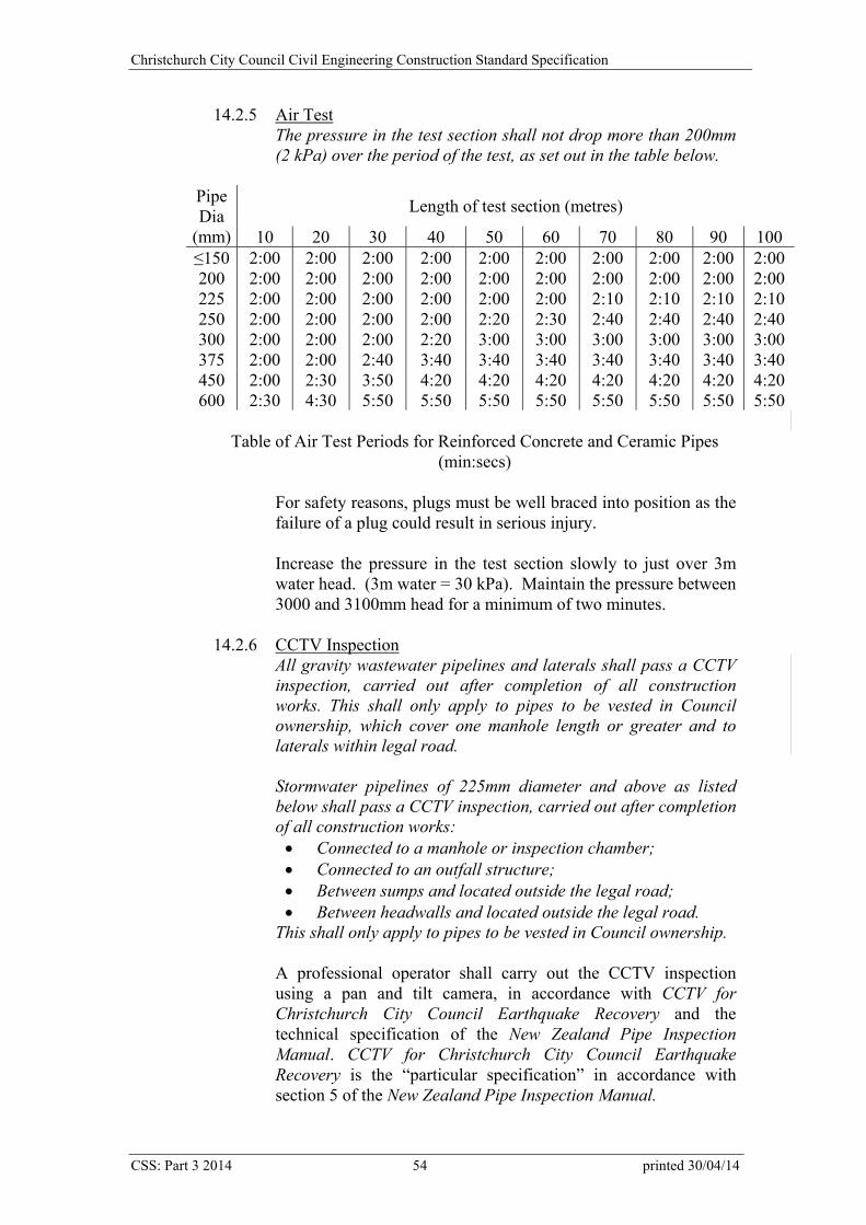
Christchurch City Council Civil Engineering Construction Standard Specification
14.2.5 Air Test The pressure in the test section shall not drop more than 200mm (2 kPa) over the period of the test, as set out in the table below.
Length of test section (metres) Pipe Dia
(mm) 10 20 30 40 50 60 70 80 90 100 ≤150 2:00 2:00 2:00 2:00 2:00 2:00 2:00 2:00 2:00 2:00 200 2:00 2:00 2:00 2:00 2:00 2:00 2:00 2:00 2:00 2:00 225 2:00 2:00 2:00 2:00 2:00 2:00 2:10 2:10 2:10 2:10 250 2:00 2:00 2:00 2:00 2:20 2:30 2:40 2:40 2:40 2:40 300 2:00 2:00 2:00 2:20 3:00 3:00 3:00 3:00 3:00 3:00 375 2:00 2:00 2:40 3:40 3:40 3:40 3:40 3:40 3:40 3:40 450 2:00 2:30 3:50 4:20 4:20 4:20 4:20 4:20 4:20 4:20 600 2:30 4:30 5:50 5:50 5:50 5:50 5:50 5:50 5:50 5:50
Table of Air Test Periods for Reinforced Concrete and Ceramic Pipes
(min:secs) For safety reasons, plugs must be well braced into position as the failure of a plug could result in serious injury. Increase the pressure in the test section slowly to just over 3m water head. (3m water = 30 kPa). Maintain the pressure between 3000 and 3100mm head for a minimum of two minutes.
14.2.6 CCTV Inspection All gravity wastewater pipelines and laterals shall pass a CCTV inspection, carried out after completion of all construction works. This shall only apply to pipes to be vested in Council ownership, which cover one manhole length or greater and to laterals within legal road. Stormwater pipelines of 225mm diameter and above as listed below shall pass a CCTV inspection, carried out after completion of all construction works: Connected to a manhole or inspection chamber; Connected to an outfall structure; Between sumps and located outside the legal road; Between headwalls and located outside the legal road.
This shall only apply to pipes to be vested in Council ownership. A professional operator shall carry out the CCTV inspection using a pan and tilt camera, in accordance with CCTV for Christchurch City Council Earthquake Recovery and the technical specification of the New Zealand Pipe Inspection Manual. CCTV for Christchurch City Council Earthquake Recovery is the “particular specification” in accordance with section 5 of the New Zealand Pipe Inspection Manual.
CSS: Part 3 2014 54 printed 30/04/14
Christchurch City Council Civil Engineering Construction Standard Specification
The operator shall pan around every joint and weld and check every lateral connection and defect. The video footage in DVD format, and the accompanying CCTV log sheets for each sewer length (as per the template in the NZ Pipe Inspection Manual), showing the features and condition of all inspected manhole lengths, shall be provided to the Council as part of the as-built record submitted through the Contract Quality Plan. Video footage supplied without log sheets will not be accepted. All pipelines shall be free of debris and cleaned with a high pressure cleaner within 24 hours prior to inspection. Any debris shall be removed from the pipeline, not flushed further down the system. Inspections of dry pipelines are not acceptable. A pipeline will fail its inspection if: The pipe has visible dips or ponding of water. The pipe has visible defects, such as open or displaced
joints, improperly removed weld beads, defective or protruding laterals, cracked barrels or similar defects.
There is evidence of infiltration at joints or laterals.
14.3 Pressure Pipelines Pressure pipelines shall be water tested in-situ, to the specified in-ground pressures, when fully haunched and backfilled. Complete the Pressure Pipe Test Checksheets in Appendices XV and XVI of IDS: Part 3 – Quality Assurance, as modified by the Engineer. The Contractor shall pressure test the whole pipeline. It is recommended that testing also be carried out in shorter lengths. The Contractor may carry out intermediate air tests to a maximum of 98kPa. These tests will not be accepted as compliance tests. 14.3.1 Concrete Pipe
Test points in concrete pressure lines may comprise either three special short pipes, the central pipe being connected to the outer two by gibault type joints or alternatively a standard length pipe may be cut into three sections using a stonemason saw, the cut surfaces being protected with an epoxy coating applied strictly in accordance with the manufacturer’s instructions. Pipes shall be left full of water for a minimum of 24 hours before the tests, to allow them to become fully hydrated.
CSS: Part 3 2014 55 printed 30/04/14
Christchurch City Council Civil Engineering Construction Standard Specification
Increase the pressure. The rate of pressure increase or decrease shall not exceed 70 kPa per minute and no pressure surges will be permitted. Working Pressure Test Increase the pressure to the specified working pressure. The pressure shall be maintained for a period of three hours and the pipe shall show no water loss. Maximum Operating Pressure Test Increase the pressure to the specified maximum operating pressure. The pressure shall be maintained for a period of five minutes and the water loss from the pipe (measured in millilitres per hour) shall not exceed 0.3 x length (metres) x diameter (millimetres). The loss from the line shall be determined by measuring, with an accurate water meter, the amount of water required to hold the pipe at test pressure.
14.3.2 Polyethylene Pipe up to DN 315 A pressure test shall be carried out in accordance with clause 6.3.4.4 and Appendix M Method 7 of AS/NZS 2566.2 “Buried flexible pipelines – Installation”. A graphical plot of the pressure test shall be supplied to the Engineer with the test readings. Further to clause M7.6, the minimum monitoring period shall be 90 mins (i.e. not 30 mins to clause 6.3.4.4 (c) but 90 mins to clause (d)) and the allowable pressure drop is from the maximum rebound pressure achieved over the monitoring period, typically experienced within the first 30 mins. The clause M7.5 (c) equation and (d) in AS/NZS 2566.2: 2002 were incorrect. The 2013 amendment provides the correct equations. The graphical plot shall be generated by a calibrated data logger and shall clearly show the pressure fluctuations, the rebound and the decay curve. The Contractor shall ensure air does not enter the pipeline either during filling from a hydrant or if using a waterblaster to pressurise the line. The Contractor shall present a methodology to remove the air, typically through swabbing, opening valves or flushing. This may require additional isolation valves for testing in sections or additional air egress points.
CSS: Part 3 2014 56 printed 30/04/14
Christchurch City Council Civil Engineering Construction Standard Specification
The test pressure shall not exceed 1.25 times the rated pressure of the lowest rated component but shall be at least 1.25 times the specified maximum operating pressure.
14.3.3 Polyethylene Pipe over DN 315 A pressure test shall be carried out in accordance with clause 6.3.4.2 and Appendix M Method 5 of AS/NZS 2566.2. A graphical plot of the pressure test shall be supplied to the Engineer with the test readings. Swab the pipeline to remove air before carrying out the pressure test.
14.3.4 Self Tapping Electrofusion Saddles A pressure test shall be carried out in accordance with clause 6.3.4.5 and Appendix M Method 8 of AS/NZS 2566.2.
14.3.5 PVC, Ductile Iron, Glass Reinforced Plastic Pipe A pressure test shall be carried out in accordance with clause 6.3.4.1 and Appendix M Method 4 of AS/NZS 2566.2. The test pressure shall not exceed 1.25 times the rated pressure of the lowest rated component but shall be at least 1.25 times the specified maximum operating pressure.
14.4 Vacuum Sewer Tests Vacuum testing of all vacuum mains, including vacuum service laterals, shall be undertaken in accordance with WSA-06 Vacuum Sewerage Code of Australia, Section 41.4. The ‘Complete Sewer’ vacuum test as specified in WSA-06 Section 41.4.4 may be applied to complete zones (mains) individually, or to the entire system. Vacuum interface valves shall be removed and the pipe connection plugged, or alternatively if provided the isolation valve in each chamber shall be closed. Vacuum testing must not be carried out against interface valves as the valves may not seal perfectly during the test. The vacuum pressure test record chart/plot shall be provided with the Compliance Requirements Checksheet.
14.5 Polyethylene Pipe Weld Tests Welds shall be inspected in the field and assessed in accordance with the requirements of AS/NZS 2033 “Installation of polyethylene pipe systems”.
Testing shall be carried out in an approved laboratory. Additional test joints shall be made and tested if there is any change to machine, operator, pipe supplier or PE material.
CSS: Part 3 2014 57 printed 30/04/14

Christchurch City Council Civil Engineering Construction Standard Specification
14.5.1 Pre-construction Joint Testing – Electrofusion For pipes with nominal diameters 90mm and larger, joints shall be tested in accordance with ISO 13954 “Plastics pipes and fittings - Peel decohesion test for polyethylene (PE) electrofusion assemblies of nominal outside diameter greater than or equal to 90 mm”. For pipe diameters smaller than 90mm, joints shall be tested in accordance with ISO 13955 “Plastics pipes and fittings - Crushing decohesion test for polyethylene (PE) electrofusion assemblies”. The Contractor shall complete two joints for each pipe diameter and material, using the machine and operator named in the Contract Quality Plan. Results shall include a commentary on and photos of the failure mechanism, including: peel depth and quality, ovality, gaps, witness mark and insertion into the coupler, joint alignment, melt flow into cavity. Failed joint samples shall be made available to the Engineer if requested. The relevant jointing log sheet and a graphical plot of the load versus extension shall be supplied for each test. Ductility shall be evident through the plot showing a rounded top and an extended sloping recession leg. The load extension graph may be used by the Engineer in assessing the results of the test.
14.5.2 Pre-construction Joint Testing – Electrofusion Saddles Saddle joints shall be tested in accordance with ISO 13956 “Decohesion test of polyethylene (PE) saddle fusion joints - Evaluation of ductility of fusion joint interface by tear test”. The Contractor shall complete two joints for each pipe diameter and material, using the machine and operator named in the Contract Quality Plan. Results shall include a commentary on and photos of the failure mechanism, including: peel depth and quality, ovality, gaps, melt flow into cavity. Failed joint samples shall be made available to the Engineer if requested.
14.5.3 Pre-construction Joint Testing – Butt Fusion One joint and one section of virgin pipe, for each pipe diameter and material type supplied for the project, shall be tested in accordance with ISO 13953 “Polyethylene (PE) pipes and fittings - Determination of the tensile strength and failure mode of test pieces from a butt-fused joint”. Results shall include a commentary on the failure mechanism. Failed joint samples shall be made available to the Engineer if requested.
CSS: Part 3 2014 58 printed 30/04/14
Christchurch City Council Civil Engineering Construction Standard Specification
The Contractor shall complete the joint using the machine and operator named in the Contract Quality Plan, to demonstrate that the methodology and fusion parameters proposed will produce acceptable fusion joints. The weld bead shall comply with clause 7.4.7 – Bead Profile. The relevant jointing log sheet and a graphical plot of the load versus extension shall be supplied for each test. Ductility shall be evident through the plot showing a rounded top and an extended sloping recession leg. The load-extension graph may be used by the Engineer in assessing the results of the test. The joint must fail at a stress which is greater than 0.9 of the virgin pipe material. Test pieces with a wall thickness < 20 mm shall rupture in a ductile manner. The cut-out joints shall be of sufficient length to make test pieces that comply with the requirements of ISO 13953 for Type A test specimens. Where the pipe wall thickness > 25 mm, both Type A and Type B test specimens shall be tested. A modified Type A test piece shall be produced by machining a similar amount from each side of the test piece to reduce the wall thickness to 22 mm ±2 mm. If satisfactory tensile test results cannot be obtained and appropriate ductility of the rupture surface is not illustrated by the load-extension graph and associated photographs, the Contractor shall provide the Engineer with details of the proposed actions to determine the cause of the problem, through the provision of a Non-Conformance Report. No further pipe installation shall take place until the corrective action is accepted.
14.5.4 Joint Testing During Construction – Electrofusion One site constructed joint shall be tested for each 20 joints constructed for each differing diameter or material, in accordance with clause 14.5.1 – Preconstruction Joint Testing - Electrofusion. Where the length is between 100m and 50m, one joint shall be tested. Lengths less than 50m shall require only pre-construction testing. The Engineer shall select the joints for testing. The Contractor shall instruct the approved laboratory to immediately forward all weld test results directly to the Engineer. Failure of any joint test will require the Contractor to follow the process set out in clause 14.5.7 – Joint test failures.
14.5.5 Joint Testing During Construction –Electrofusion Saddles One site constructed joint shall be tested for each 20 joints constructed for each differing diameter or material, in accordance with clause 14.5.2 – Preconstruction Joint Testing –
CSS: Part 3 2014 59 printed 30/04/14
Christchurch City Council Civil Engineering Construction Standard Specification
Electrofusion Saddles. The Engineer shall select the joints for testing. The Contractor shall instruct the approved laboratory to immediately forward all weld test results directly to the Engineer. Failure of any joint test will require the Contractor to follow the process set out in clause 14.5.7 – Joint test failures.
14.5.6 Joint Testing During Construction – Butt Fusion One joint per pipeline for every 20 joints constructed shall be tested in accordance with clause 14.5.3 – Preconstruction Joint Testing - Butt Fusion. Where the pipe wall thickness > 25 mm, Type B test specimens shall be tested. The Contractor shall instruct the approved laboratory to immediately forward all weld test results directly to the Engineer. Failure of any joint test will require the Contractor to follow the process set out in clause 14.5.7 – Joint test failures.
14.5.7 Joint Test Failures Where a weld fails the test, the Contractor shall cease welding and no further pipe installation shall be carried out. The Contractor shall review the jointing process and test commentary to determine the cause of the unsatisfactory joint, the proposed corrective actions and report these to the Engineer, through a Non-Conformance Report (NCR) complying with IDS, clause 3.7.1 - Control of non-conforming work. The diagram illustrates the process. If the Engineer considers that the weld has failed for reasons beyond the approved welder’s control, the welding methodology shall be amended to incorporate any corrective actions arising from the NCR and then utilised for all subsequent welds. If the non-conforming weld is due to the approved welder’s action, the Contractor shall remove the ‘previous’ joint for testing, as per the chronological order of jointing. The section of pipe from the location of the failed joint to the last passing test shall be quarantined and not installed. If the previous joint(s) are at a tee, these shall not be removed for testing and the next through (straight) joint shall be tested. If this joint complies, the welder shall produce a ‘test’ joint. Jointing shall not recommence until the NCR process is completed as above and the welder has received complying weld test results from the ‘previous’ joint and from the ‘test’ joint, as set out in the flow chart.
CSS: Part 3 2014 60 printed 30/04/14
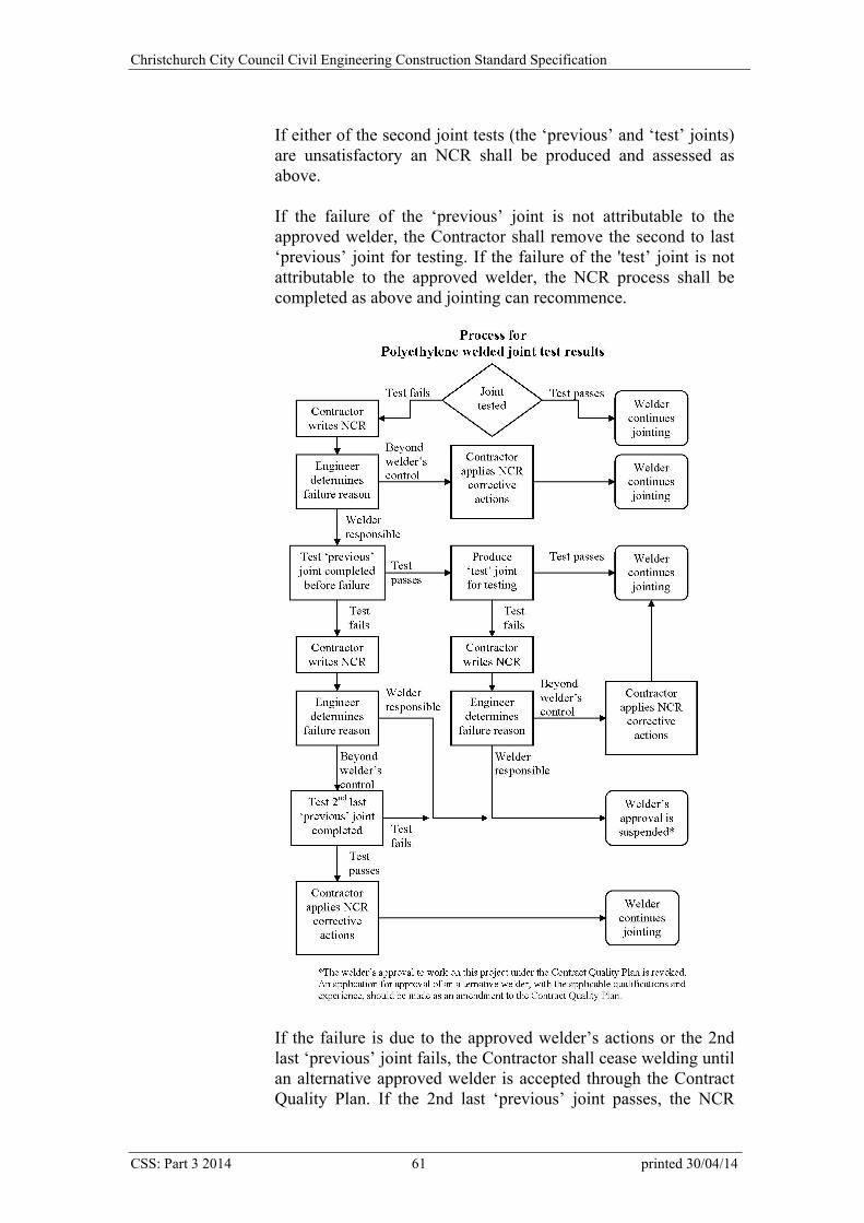
Christchurch City Council Civil Engineering Construction Standard Specification
If either of the second joint tests (the ‘previous’ and ‘test’ joints) are unsatisfactory an NCR shall be produced and assessed as above. If the failure of the ‘previous’ joint is not attributable to the approved welder, the Contractor shall remove the second to last ‘previous’ joint for testing. If the failure of the 'test’ joint is not attributable to the approved welder, the NCR process shall be completed as above and jointing can recommence.
If the failure is due to the approved welder’s actions or the 2nd last ‘previous’ joint fails, the Contractor shall cease welding until an alternative approved welder is accepted through the Contract Quality Plan. If the 2nd last ‘previous’ joint passes, the NCR
CSS: Part 3 2014 61 printed 30/04/14
Christchurch City Council Civil Engineering Construction Standard Specification
process shall be completed as above and jointing can recommence. Continuing installation and backfill of pipe joints made prior to the ‘previous’ test failure may not occur until the Contractor has satisfied the Engineer that the joints in this pipe are satisfactory. This may require either that further joints are tested or that all the suspect joints are cut out and re-welded or a combination of both.
14.6 Flexible Pipe Ovality Test An ovality test shall be carried out on gravity pipelines in accordance with clause 6.5 of AS/NZS 2566.2 “Buried flexible pipelines – Installation”. The test shall be carried out at least seven days after the pipe surround is laid. Deformation exceeding the specified amount shall be corrected or the pipe replaced. The equation to determine the outside diameter of the prover shall be:
5.210011
sally
vd dO
Where: Od = outside diameter of prover (mm) dv1= minimum vertical internal diameter (mm) Δy sall= maximum allowable short-term vertical pipe deflection 2.5 = clearance between prover and inside of pipe The clause O2.1 (d) equation in AS/NZS 2566.2 is incorrect.
14.7 Measurement of Work and Basis of Payment The Contractor shall include the cost of all testing and associated work in the rate for pipe installation. This shall include test points in pressure pipes but shall exclude testing junctions for gravity pipes. The remedying of defects made apparent by testing shall be at the Contractor’s cost. 14.7.1 Testing Junctions
Testing junctions shall include supply, installation and plugging after testing.
14.7.2 CCTV inspection CCTV inspection shall include flushing and the provision of a video and written records to Council.
14.7.3 Polyethylene Pipe Weld Test Payment for specified sampling, testing, re-jointing and reinstatement etc of joints shall be for each complying joint. The
CSS: Part 3 2014 62 printed 30/04/14
Christchurch City Council Civil Engineering Construction Standard Specification
rate for electrofusion joint testing shall include for all time related effects associated with set up, testing, approval, re-jointing etc. If additional testing is required due to a change in machine, operator, pipe supplier or material or to prove defective work, the additional tests and any related costs shall be borne by the Contractor.
15.0 BACKFILLING Backfilling shall be carried out in accordance with CSS: Part 1 - General.
15.1 Prior to Backfilling
No backfilling shall be carried out until the Engineer has approved the method of backfilling and compaction. No backfilling shall commence until all concrete, whether used in haunching, risers, manholes or other structures, has gained sufficient strength to support the loads that will be transmitted to it. All formwork shall be removed before backfilling.
15.2 Materials Backfill to trenches shall be the specified imported material, unless the Engineer approves the use of the excavated material as backfill. There will be no payment for handling of excavated material where used as backfill.
15.3 Backfill Procedure
Backfill shall be placed so that no sudden or excessive loading is transmitted to the pipeline or its accessories. The pipe shall not be moved or damaged during placing or compaction of backfill. Particular care shall be taken to compact the backfilling around risers. Well point, well or test holes shall be completely filled with coarse sand or approved alternative. Where watering-in is used, the surface layer of the backfill, if segregated, shall be removed or treated.
15.4 Quality Assurance
The Contractor shall provide records of compliance tests carried out on trench backfill as required by CSS: Part 1 - General, to comply with IDS: Part 3 - Quality Assurance.
CSS: Part 3 2014 63 printed 30/04/14
Christchurch City Council Civil Engineering Construction Standard Specification
Records of these tests shall be supplied at regular intervals, to provide confirmation of ongoing testing. Details of the proposed methods and frequency of such activities, and the reporting of these, shall be set out in the Contractor’s Contract Quality Plan.
15.5 Measurement of Works and Basis of Payment 15.5.1 Imported Backfill
Imported backfill shall include the supply of backfill material to replace rejected material, any handling between the on-site stockpile and the trench and the removal and disposal of that rejected material. Imported backfill shall be paid by solid measure, to the nearest 0.1m3. For concrete pipes, the volume shall be determined from the excavation width and the depth from the subgrade to the centreline of the pipe where the pipe diameter is 525mm or less. Where the pipe is greater than 525mm diameter, the depth shall be to the top of the pipe haunching and the volume shall be reduced by the volume of the pipe and surround above the level of the haunching. The trench width shall be ‘G’ or ‘N’ as specified for the excavation. For flexible and ceramic pipes, the volume shall be determined from the trench width ‘G’ or ‘N’ and the depth from the subgrade to the top of the haunching or 150mm above the top of the pipe.
15.5.2 Filling to Unsuitable Foundations Filling to unsuitable foundations shall be paid per m3 solid volume of fill placed, to the nearest 0.1m3, and shall include supply, placing, compaction and testing. Measurement of filling shall be determined from the volume of unsuitable foundations being filled.
15.5.3 Testing Benkelman Beam testing shall be paid per manhole length or per 100m for pressure pipe for complying results. Backfill testing ordered by the Engineer using the nuclear densometer shall be paid per complying result. The cost of all backfill compliance testing required under clause 15.4 – Quality Assurance shall be included in the rates for pipe laying.
16.0 ADJUSTING MANHOLES TO ALTERED SURFACE LEVELS
Manhole frames and tops shall be adjusted in accordance with SD 306.
CSS: Part 3 2014 64 printed 30/04/14
Christchurch City Council Civil Engineering Construction Standard Specification
16.1 Materials
All materials used shall comply with clause 12.2 – Quality Assurance. Cast or ductile iron frames may be fixed into the rebates with asphaltic concrete or cement sand mortar or concrete with a 6mm maximum aggregate size. Accelerating admixtures may be used. Under no circumstances shall frames be concreted in at the time the margin is poured. Where asphaltic concrete is used the surfaces of the frame and concrete rebate shall be primed with bituminous emulsion and the asphaltic concrete placed and thoroughly rammed in 30mm layers.
16.2 Raising of Manhole Frames
The neck of a standard or flush manhole shall not be deeper than 600mm once adjusted. Where the neck will not exceed this limit, apply the procedure relevant to the type of manhole. 16.2.1 Raising the Frame for a Standard Manhole within the Rebate
The 100mm frame of a standard manhole with a 100mm deep margin may be packed up on cement mortar or fine aggregate concrete and the top of the frame raised to a maximum of 65mm above the concrete surface provided the raised frame is laterally supported by asphaltic concrete. The maximum thickness of cement mortar to support frames shall not exceed 25mm. Concrete with a maximum aggregate size of 6mm shall be used to support frames for thicknesses over 25mm.
16.2.2 Raising the Frame for a Bottleneck Manhole
For “bottleneck” manholes the 200mm frames and concrete surround shall be removed and replaced with 100mm frames. The exterior dimensions of the cast in-situ manhole top shall not exceed the equivalent exterior dimensions of the manhole. The new concrete top shall be reinforced with one peripheral 16mm diameter bar with 50mm cover. The existing brickwork shall be prepared in all areas where new concrete shall be poured against it.
16.2.3 Deepening the Rebate Perimeter concrete to the frame rebate shall be a minimum of 200mm wide at all points. Dimensions to the finished surface shall comply with SD 306.
16.3 Raising of Manhole Tops
Where the depth from the top of the frame to the underside of the slab exceeds 600mm, the top and walls shall be raised.
CSS: Part 3 2014 65 printed 30/04/14
Christchurch City Council Civil Engineering Construction Standard Specification
Standard manhole slab tops may be reused but the tops of “bottleneck” manholes with 200mm frames shall not be reused. In flush tanks, flush manholes and manholes with turning valves, the chain hook shall be relocated. 16.3.1 Standard Manholes
Vent structures shall be extended, where the vent cover is being reused.
16.3.2 Bottleneck Manholes The bottleneck shall be removed and either vertical walls constructed from the original springing or a precast manhole riser installed. Vent structures shall be broken down and sealed off and a vented circular manhole cover installed.
16.3.3 Precast Circular Manholes Units shall be used to raise the top. If the adjustment required cannot be achieved solely by the use of riser rings then raise both the top and the frame.
16.4 Lowering the Surface Level
16.4.1 Standard Manholes without Vents The concrete top shall be removed and the walls cut down the required amount. The top of the cut wall shall be made true and even with cement mortar and the top reset on a cement mortar bed.
16.4.2 Standard Vented Manholes with Removable Vent Gratings
When lowering less than 125mm, the vent may be adapted by cutting down the walls, to provide a vent opening height of 50mm with a vent upstand above the vent drain of 150mm. The top shall be treated as described in clause 16.4.1 – Standard Manholes Without Vents. When lowering more than 125mm, a new style precast top with the vented circular manhole cover shall be used. The old vent shall be broken down and sealed off.
16.4.3 Vented Manholes with a Fixed Vent Grating The top may be lowered without altering the vent provided the soffit of the slab does not finish lower than the top of the vent opening pipe. Where this will occur a new style precast vented top shall be used.
16.4.4 Bottleneck manholes.
Lowering of less than 100mm may be accommodated by fitting 100mm frames to replace 200mm frames, as described in clause 16.2.2 – Raising the Frame for a Bottleneck Manhole. If the top
CSS: Part 3 2014 66 printed 30/04/14

Christchurch City Council Civil Engineering Construction Standard Specification
is to be lowered more than 100mm, the alteration shall be carried out as described in clause 16.3.2 – Bottleneck Manholes.
16.4.5 Precast Circular Manholes
The walls of the precast unit shall be cut down, taking special care to avoid spalling and/or cracking of the unit. After cutting down the top edge shall be reformed using the special former. An approved sealing strip shall be placed between any slab and extension to walls on precast manholes to form a watertight joint. Alternatively, lowering may be achieved in some cases by removing one of the riser rings and replacing it with another of the appropriate height.
16.5 Protection of System
Before any alteration work is carried out on manholes or flush tanks, the existing inverts etc shall be covered with decking to prevent the entry of debris that could cause blockages.
16.6 Protection of Structures
Traffic shall be kept off all structures until they have achieved a strength of 25 MPa. The use of steel plates to cover new concrete work and prevent traffic loading shall be permitted in accordance with CSS: Part 1 - General. It is essential however that there is sufficient clearance between the underside of the plate and the new concrete margin or newly bedded frame to enable traffic to pass over the top of the manhole without the load being transmitted to the new concrete work.
16.7 Measurement of Works and Basis of Payment Adjusting manholes shall be paid as a lump sum per item. Adjustments to vents shall be included in this sum. 16.7.1 Manholes Adjusted Separately from Drainage Works
The rate shall include the restoration of the surrounding surface.
17.0 RESTORATION Restoration shall be carried out in accordance with CSS: Part 1 - General and the Works Access Permit (WAP) conditions, where applicable. Apply for a Corridor Access Request (CAR) at www.beforeudig.co.nz. 17.1 Measurement of Works and Basis of Payment
Restoration from subgrade level shall be measured on the lineal metre of pipe installed, to the nearest 0.1m, which shall include restoration to any
CSS: Part 3 2014 67 printed 30/04/14

Christchurch City Council Civil Engineering Construction Standard Specification
CSS: Part 3 2014 68 printed 30/04/14
structures installed on the pipe. Restoration includes additional sawcutting, bandaging where necessary and additional sealing width as detailed in CSS: Part 1 clause 30.0 – Restoration and Final Surfacing.
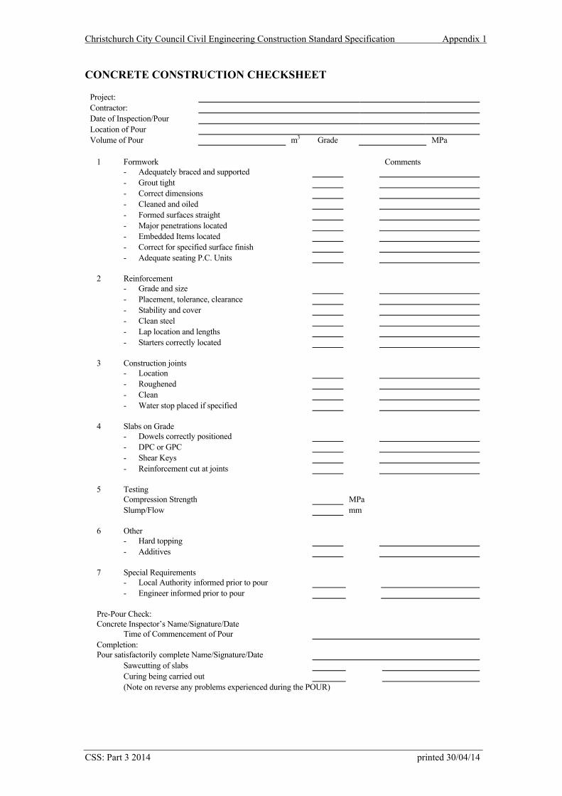
Christchurch City Council Civil Engineering Construction Standard Specification Appendix 1
CONCRETE CONSTRUCTION CHECKSHEET
Project: Contractor: Date of Inspection/Pour Location of Pour Volume of Pour m3 Grade MPa
1 Formwork Comments - Adequately braced and supported - Grout tight - Correct dimensions - Cleaned and oiled - Formed surfaces straight - Major penetrations located - Embedded Items located - Correct for specified surface finish - Adequate seating P.C. Units 2 Reinforcement - Grade and size - Placement, tolerance, clearance - Stability and cover - Clean steel - Lap location and lengths - Starters correctly located 3 Construction joints - Location - Roughened - Clean - Water stop placed if specified 4 Slabs on Grade - Dowels correctly positioned - DPC or GPC - Shear Keys - Reinforcement cut at joints 5 Testing Compression Strength MPa Slump/Flow mm 6 Other - Hard topping - Additives 7 Special Requirements - Local Authority informed prior to pour - Engineer informed prior to pour Pre-Pour Check: Concrete Inspector’s Name/Signature/Date
Time of Commencement of Pour Completion: Pour satisfactorily complete Name/Signature/Date
Sawcutting of slabs Curing being carried out (Note on reverse any problems experienced during the POUR)
CSS: Part 3 2014 printed 30/04/14
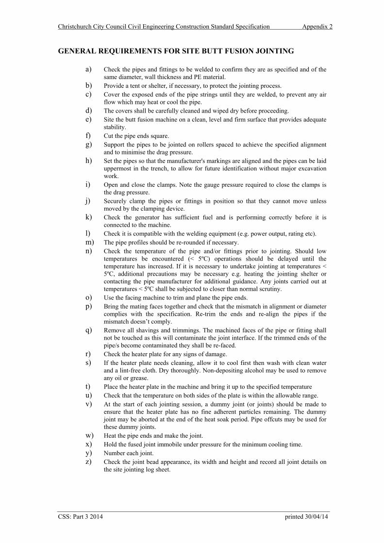
Christchurch City Council Civil Engineering Construction Standard Specification Appendix 2
GENERAL REQUIREMENTS FOR SITE BUTT FUSION JOINTING
a) Check the pipes and fittings to be welded to confirm they are as specified and of the same diameter, wall thickness and PE material.
b) Provide a tent or shelter, if necessary, to protect the jointing process. c) Cover the exposed ends of the pipe strings until they are welded, to prevent any air
flow which may heat or cool the pipe. d) The covers shall be carefully cleaned and wiped dry before proceeding. e) Site the butt fusion machine on a clean, level and firm surface that provides adequate
stability. f) Cut the pipe ends square. g) Support the pipes to be jointed on rollers spaced to achieve the specified alignment
and to minimise the drag pressure. h) Set the pipes so that the manufacturer's markings are aligned and the pipes can be laid
uppermost in the trench, to allow for future identification without major excavation work.
i) Open and close the clamps. Note the gauge pressure required to close the clamps is the drag pressure.
j) Securely clamp the pipes or fittings in position so that they cannot move unless moved by the clamping device.
k) Check the generator has sufficient fuel and is performing correctly before it is connected to the machine.
l) Check it is compatible with the welding equipment (e.g. power output, rating etc). m) The pipe profiles should be re-rounded if necessary. n) Check the temperature of the pipe and/or fittings prior to jointing. Should low
temperatures be encountered (< 5ºC) operations should be delayed until the temperature has increased. If it is necessary to undertake jointing at temperatures < 5ºC, additional precautions may be necessary e.g. heating the jointing shelter or contacting the pipe manufacturer for additional guidance. Any joints carried out at temperatures < 5ºC shall be subjected to closer than normal scrutiny.
o) Use the facing machine to trim and plane the pipe ends. p) Bring the mating faces together and check that the mismatch in alignment or diameter
complies with the specification. Re-trim the ends and re-align the pipes if the mismatch doesn’t comply.
q) Remove all shavings and trimmings. The machined faces of the pipe or fitting shall not be touched as this will contaminate the joint interface. If the trimmed ends of the pipe/s become contaminated they shall be re-faced.
r) Check the heater plate for any signs of damage. s) If the heater plate needs cleaning, allow it to cool first then wash with clean water
and a lint-free cloth. Dry thoroughly. Non-depositing alcohol may be used to remove any oil or grease.
t) Place the heater plate in the machine and bring it up to the specified temperature u) Check that the temperature on both sides of the plate is within the allowable range. v) At the start of each jointing session, a dummy joint (or joints) should be made to
ensure that the heater plate has no fine adherent particles remaining. The dummy joint may be aborted at the end of the heat soak period. Pipe offcuts may be used for these dummy joints.
w) Heat the pipe ends and make the joint. x) Hold the fused joint immobile under pressure for the minimum cooling time. y) Number each joint. z) Check the joint bead appearance, its width and height and record all joint details on
the site jointing log sheet.
CSS: Part 3 2014 printed 30/04/14
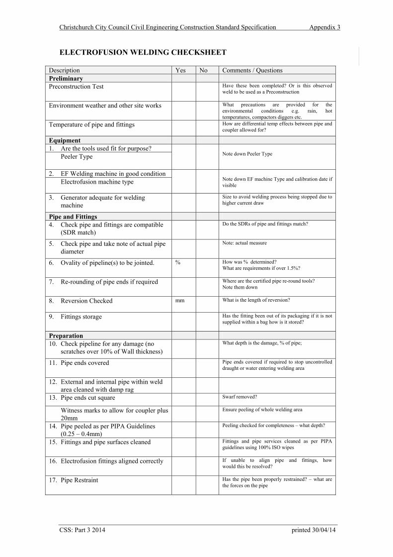
Christchurch City Council Civil Engineering Construction Standard Specification Appendix 3
ELECTROFUSION WELDING CHECKSHEET
Description Yes No Comments / Questions Preliminary Preconstruction Test Have these been completed? Or is this observed
weld to be used as a Preconstruction
Environment weather and other site works
What precautions are provided for the environmental conditions e.g. rain, hot temperatures, compactors diggers etc.
Temperature of pipe and fittings
How are differential temp effects between pipe and coupler allowed for?
Equipment
1. Are the tools used fit for purpose? Peeler Type
Note down Peeler Type
2. EF Welding machine in good condition Electrofusion machine type
Note down EF machine Type and calibration date if visible
3. Generator adequate for welding machine
Size to avoid welding process being stopped due to higher current draw
Pipe and Fittings
4. Check pipe and fittings are compatible (SDR match)
Do the SDRs of pipe and fittings match?
5. Check pipe and take note of actual pipe diameter
Note: actual measure
6. Ovality of pipeline(s) to be jointed.
% How was % determined? What are requirements if over 1.5%?
7. Re-rounding of pipe ends if required Where are the certified pipe re-round tools? Note them down
8. Reversion Checked
mm What is the length of reversion?
9. Fittings storage
Has the fitting been out of its packaging if it is not supplied within a bag how is it stored?
Preparation
10. Check pipeline for any damage (no scratches over 10% of Wall thickness)
What depth is the damage, % of pipe;
11. Pipe ends covered Pipe ends covered if required to stop uncontrolled draught or water entering welding area
12. External and internal pipe within weld area cleaned with damp rag
13. Pipe ends cut square Swarf removed?
Witness marks to allow for coupler plus 20mm
Ensure peeling of whole welding area
14. Pipe peeled as per PIPA Guidelines (0.25 – 0.4mm)
Peeling checked for completeness – what depth?
15. Fittings and pipe surfaces cleaned Fittings and pipe services cleaned as per PIPA guidelines using 100% ISO wipes
16. Electrofusion fittings aligned correctly If unable to align pipe and fittings, how would this be resolved?
17. Pipe Restraint Has the pipe been properly restrained? – what are the forces on the pipe
CSS: Part 3 2014 printed 30/04/14
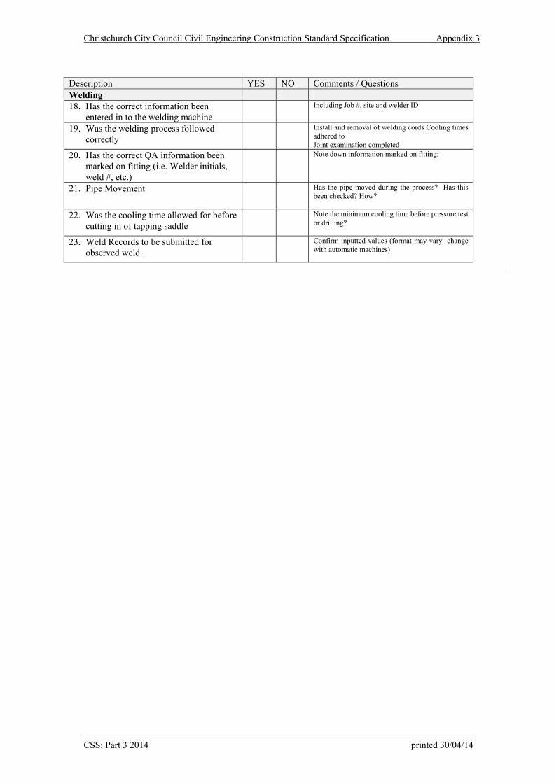
Christchurch City Council Civil Engineering Construction Standard Specification Appendix 3
CSS: Part 3 2014 printed 30/04/14
Description YES NO Comments / Questions Welding 18. Has the correct information been
entered in to the welding machine Including Job #, site and welder ID
19. Was the welding process followed correctly
Install and removal of welding cords Cooling times adhered to Joint examination completed
20. Has the correct QA information been marked on fitting (i.e. Welder initials, weld #, etc.)
Note down information marked on fitting;
21. Pipe Movement Has the pipe moved during the process? Has this been checked? How?
22. Was the cooling time allowed for before cutting in of tapping saddle
Note the minimum cooling time before pressure test or drilling?
23. Weld Records to be submitted for observed weld.
Confirm inputted values (format may vary change with automatic machines)
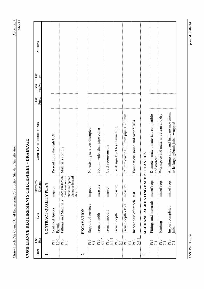
Chr
istc
hurc
h C
ity C
ounc
il C
ivil
Eng
inee
ring
Con
stru
ctio
n S
tand
ard
Spe
cifi
catio
n
App
endi
x 4
She
et 1
CO
MP
LIA
NC
E R
EQ
UIR
EM
EN
TS
CH
EC
KS
HE
ET
- D
RA
INA
GE
ITE
M
CSS
RE
F
TA
SK
T
ES
T S
TD
/ D
ESC
RIP
C
OM
PL
IAN
CE
RE
QU
IRE
ME
NT
S
TE
ST
FR
EQ
. P
AS
S
YE
S/N
O
TE
ST
BY
A
CT
ION
S
1
C
ON
TR
AC
T Q
UA
LIT
Y P
LA
N
P
t 1
10.0
C
onfi
ned
Spa
ces
Per
mit
in
spec
t P
rese
nt c
opy
thro
ugh
CQ
P
Pt 3
3.
0 F
itti
ngs
and
Mat
eria
lsw
ww
.ccc
.gov
t.nz
/bus
ines
s/co
nstr
uct
iond
evel
opm
ent/
appr
oved
mat
eri
als.
aspx
Mat
eria
ls c
ompl
y
2
E
XC
AV
AT
ION
P
t 3
5.1
Sup
port
of
serv
ices
in
spec
t N
o ex
isti
ng s
ervi
ces
disr
upte
d
P
t 3
6.4.
2 T
renc
h w
idth
m
easu
re
300m
m w
ider
than
pip
e co
llar
P
t 3
6.4.
4 T
renc
h su
ppor
t in
spec
t O
SH
req
uire
men
ts
P
t 3
6.4
Tre
nch
dept
h
mea
sure
T
o de
sign
leve
l les
s ha
unch
ing
P
t 3
8.7
Tre
nch
dept
h -
PV
C
mea
sure
75
0mm
cov
er +
300
mm
pip
e +
200
mm
P
t 3
6.4.
3 In
spec
t bas
e of
tren
ch
test
F
ound
atio
ns s
ound
and
ove
r 50
kPa
3
M
EC
HA
NIC
AL
JO
INT
ING
EX
CE
PT
PL
AS
TIC
S
P
t 3
7.1
Fit
ting
s an
d m
ater
ials
m
anuf
req
s D
iam
eter
s m
atch
, mat
eria
ls c
ompa
tibl
e an
d co
rrec
t
P
t 3
7.1
Join
ting
m
anuf
req
s W
orks
pace
and
mat
eria
ls c
lean
and
dry
P
t 3
7.1
Insp
ect c
ompl
eted
jo
int
man
uf r
eqs
All
fit
ting
s sn
ug a
nd f
irm
, no
mov
emen
t or
leak
age,
gib
ault
join
ts w
rapp
ed
CS
S: P
art 3
201
4 pr
inte
d 30
/04/
14
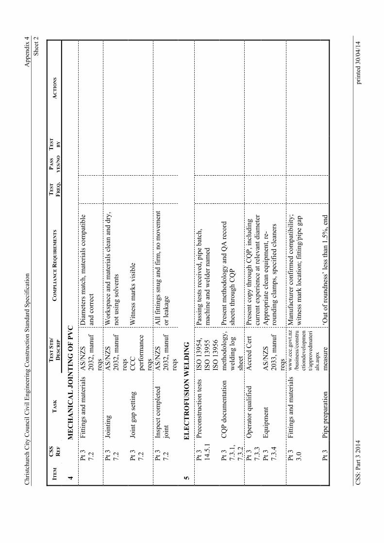
Chr
istc
hurc
h C
ity C
ounc
il C
ivil
Eng
inee
ring
Con
stru
ctio
n S
tand
ard
Spe
cifi
catio
n
App
endi
x 4
She
et 2
CS
S: P
art 3
201
4 pr
inte
d 30
/04/
14
ITE
M
CSS
RE
F
TA
SK
T
ES
T S
TD
/ D
ESC
RIP
C
OM
PL
IAN
CE
RE
QU
IRE
ME
NT
S
TE
ST
FR
EQ
. P
AS
S
YE
S/N
O
TE
ST
BY
A
CT
ION
S
4
M
EC
HA
NIC
AL
JO
INT
ING
OF
PV
C
P
t 3
7.2
Fit
ting
s an
d m
ater
ials
A
S/N
ZS
20
32, m
anuf
re
qs
Dia
met
ers
mat
ch, m
ater
ials
com
pati
ble
and
corr
ect
P
t 3
7.2
Join
ting
A
S/N
ZS
20
32, m
anuf
re
qs
Wor
kspa
ce a
nd m
ater
ials
cle
an a
nd d
ry,
not u
sing
sol
vent
s
P
t 3
7.2
Join
t gap
set
ting
C
CC
pe
rfor
man
ce
reqs
Wit
ness
mar
ks v
isib
le
P
t 3
7.2
Insp
ect c
ompl
eted
jo
int
AS
/NZ
S
2032
, man
uf
reqs
All
fit
ting
s sn
ug a
nd f
irm
, no
mov
emen
t or
leak
age
5
E
LE
CT
RO
FU
SIO
N W
EL
DIN
G
P
t 3
14.5
.1P
reco
nstr
ucti
on te
sts
ISO
139
54,
ISO
139
55
ISO
139
56
Pas
sing
test
s re
ceiv
ed, p
ipe
batc
h,
mac
hine
and
wel
der
nam
ed
P
t 3
7.3.
1,
7.3.
2
CQ
P d
ocum
enta
tion
m
etho
dolo
gy,
wel
ding
log
shee
t
Pre
sent
met
hodo
logy
and
QA
rec
ord
shee
ts th
roug
h C
QP
P
t 3
7.3.
3 O
pera
tor
qual
ifie
d A
ccre
d C
ert
Pre
sent
cop
y th
roug
h C
QP
, inc
ludi
ng
curr
ent e
xper
ienc
e at
rel
evan
t dia
met
er
P
t 3
7.3.
4 E
quip
men
t A
S/N
ZS
20
33, m
anuf
re
qs
App
ropr
iate
cle
an e
quip
men
t, re
-ro
undi
ng c
lam
ps, s
peci
fied
cle
aner
s
Pt 3
3.
0 F
itti
ngs
and
mat
eria
ls
ww
w.c
cc.g
ovt.n
z/b
usin
ess/
cons
tru
ctio
ndev
elop
men
t/ap
prov
edm
ater
ial
s.as
px
Man
ufac
ture
r co
nfir
med
com
pati
bili
ty;
wit
ness
mar
k lo
cati
on; f
itti
ng/p
ipe
gap
P
t 3
Pip
e pr
epar
atio
n m
easu
re
‘Out
of
roun
dnes
s’ le
ss th
an 1
.5%
, end
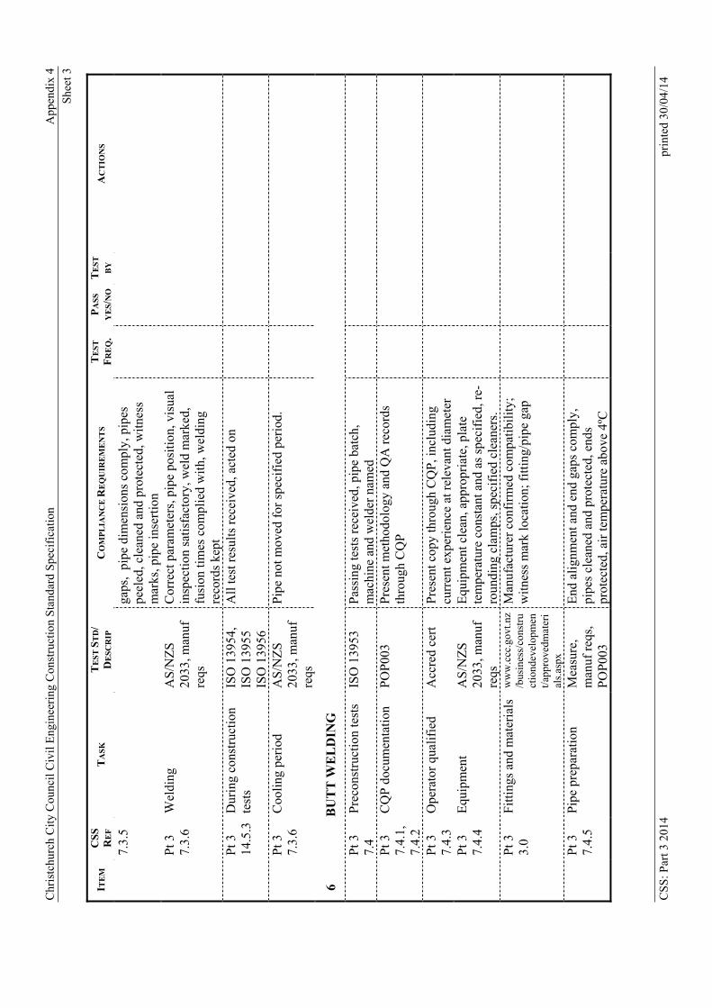
Chr
istc
hurc
h C
ity C
ounc
il C
ivil
Eng
inee
ring
Con
stru
ctio
n S
tand
ard
Spe
cifi
catio
n
App
endi
x 4
She
et 3
CS
S: P
art 3
201
4 pr
inte
d 30
/04/
14
ITE
M
CSS
RE
F
TA
SK
T
ES
T S
TD
/ D
ESC
RIP
C
OM
PL
IAN
CE
RE
QU
IRE
ME
NT
S
TE
ST
FR
EQ
. P
AS
S
YE
S/N
O
TE
ST
BY
A
CT
ION
S
7.3.
5 ga
ps,
pipe
dim
ensi
ons
com
ply,
pip
es
peel
ed, c
lean
ed a
nd p
rote
cted
, wit
ness
m
arks
, pip
e in
sert
ion
Pt 3
7.
3.6
Wel
ding
A
S/N
ZS
20
33, m
anuf
re
qs
Cor
rect
par
amet
ers,
pip
e po
siti
on, v
isua
l in
spec
tion
sat
isfa
ctor
y, w
eld
mar
ked,
fu
sion
tim
es c
ompl
ied
wit
h, w
eldi
ng
reco
rds
kept
P
t 3
14.5
.3D
urin
g co
nstr
ucti
on
test
s IS
O 1
3954
, IS
O 1
3955
IS
O 1
3956
All
test
res
ults
rec
eive
d, a
cted
on
P
t 3
7.3.
6 C
ooli
ng p
erio
d A
S/N
ZS
20
33, m
anuf
re
qs
Pip
e no
t mov
ed f
or s
peci
fied
per
iod.
6
B
UT
T W
EL
DIN
G
P
t 3
7.4
Pre
cons
truc
tion
test
s IS
O 1
3953
P
assi
ng te
sts
rece
ived
, pip
e ba
tch,
m
achi
ne a
nd w
elde
r na
med
P
t 3
7.4.
1,
7.4.
2
CQ
P d
ocum
enta
tion
P
OP
003
Pre
sent
met
hodo
logy
and
QA
rec
ords
th
roug
h C
QP
P
t 3
7.4.
3 O
pera
tor
qual
ifie
d A
ccre
d ce
rt
Pre
sent
cop
y th
roug
h C
QP
, inc
ludi
ng
curr
ent e
xper
ienc
e at
rel
evan
t dia
met
er
P
t 3
7.4.
4 E
quip
men
t A
S/N
ZS
20
33, m
anuf
re
qs
Equ
ipm
ent c
lean
, app
ropr
iate
, pla
te
tem
pera
ture
con
stan
t and
as
spec
ifie
d, r
e-ro
undi
ng c
lam
ps, s
peci
fied
cle
aner
s.
Pt 3
3.
0 F
itti
ngs
and
mat
eria
ls
ww
w.c
cc.g
ovt.n
z/b
usin
ess/
cons
tru
ctio
ndev
elop
men
t/ap
prov
edm
ater
ial
s.as
px
Man
ufac
ture
r co
nfir
med
com
pati
bili
ty;
wit
ness
mar
k lo
cati
on; f
itti
ng/p
ipe
gap
P
t 3
7.4.
5 P
ipe
prep
arat
ion
M
easu
re,
man
uf r
eqs,
P
OP
003
End
ali
gnm
ent a
nd e
nd g
aps
com
ply,
pi
pes
clea
ned
and
prot
ecte
d, e
nds
prot
ecte
d, a
ir te
mpe
ratu
re a
bove
4ºC
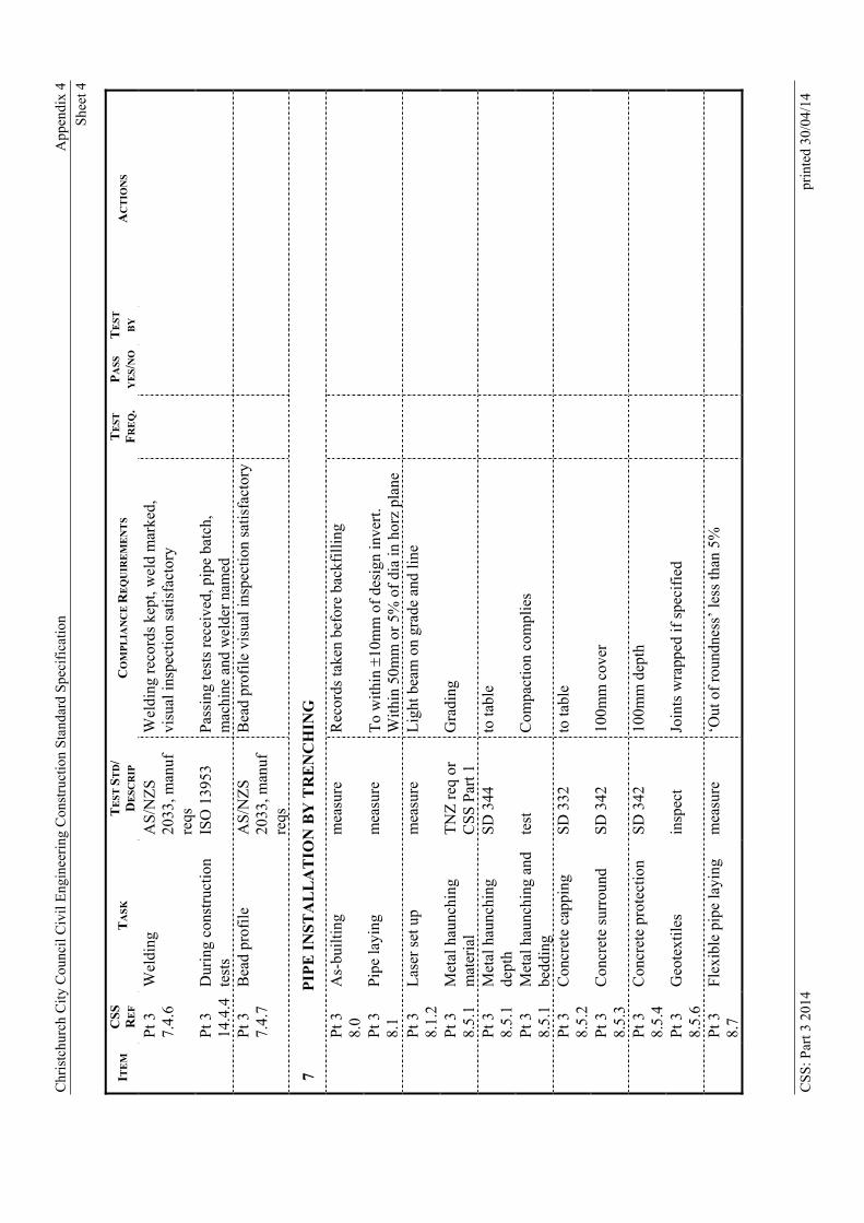
Chr
istc
hurc
h C
ity C
ounc
il C
ivil
Eng
inee
ring
Con
stru
ctio
n S
tand
ard
Spe
cifi
catio
n
App
endi
x 4
She
et 4
CS
S: P
art 3
201
4 pr
inte
d 30
/04/
14
ITE
M
CSS
RE
F
TA
SK
T
ES
T S
TD
/ D
ESC
RIP
C
OM
PL
IAN
CE
RE
QU
IRE
ME
NT
S
TE
ST
FR
EQ
. P
AS
S
YE
S/N
O
TE
ST
BY
A
CT
ION
S
P
t 3
7.4.
6 W
eldi
ng
AS
/NZ
S
2033
, man
uf
reqs
Wel
ding
rec
ords
kep
t, w
eld
mar
ked,
vi
sual
insp
ecti
on s
atis
fact
ory
P
t 3
14.4
.4D
urin
g co
nstr
ucti
on
test
s IS
O 1
3953
P
assi
ng te
sts
rece
ived
, pip
e ba
tch,
m
achi
ne a
nd w
elde
r na
med
P
t 3
7.4.
7 B
ead
prof
ile
A
S/N
ZS
20
33, m
anuf
re
qs
Bea
d pr
ofil
e vi
sual
insp
ecti
on s
atis
fact
ory
7
P
IPE
IN
ST
AL
LA
TIO
N B
Y T
RE
NC
HIN
G
P
t 3
8.0
As-
buil
ting
m
easu
re
Rec
ords
take
n be
fore
bac
kfil
ling
P
t 3
8.1
Pip
e la
ying
m
easu
re
To
wit
hin 1
0mm
of
desi
gn in
vert
. W
ithi
n 50
mm
or
5% o
f di
a in
hor
z pl
ane
P
t 3
8.1.
2 L
aser
set
up
mea
sure
L
ight
bea
m o
n gr
ade
and
line
P
t 3
8.5.
1 M
etal
hau
nchi
ng
mat
eria
l T
NZ
req
or
CS
S P
art 1
G
radi
ng
P
t 3
8.5.
1 M
etal
hau
nchi
ng
dept
h S
D 3
44
to ta
ble
P
t 3
8.5.
1 M
etal
hau
nchi
ng a
nd
bedd
ing
test
C
ompa
ctio
n co
mpl
ies
P
t 3
8.5.
2 C
oncr
ete
capp
ing
S
D 3
32
to ta
ble
P
t 3
8.5.
3 C
oncr
ete
surr
ound
S
D 3
42
100m
m c
over
P
t 3
8.5.
4 C
oncr
ete
prot
ecti
on
SD
342
10
0mm
dep
th
P
t 3
8.5.
6 G
eote
xtil
es
insp
ect
Join
ts w
rapp
ed if
spe
cifi
ed
P
t 3
8.7
Fle
xibl
e pi
pe la
ying
m
easu
re
‘Out
of
roun
dnes
s’ le
ss th
an 5
%
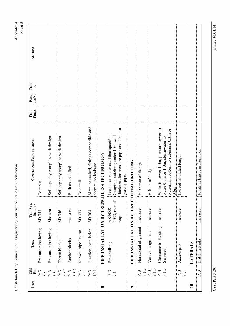
Chr
istc
hurc
h C
ity C
ounc
il C
ivil
Eng
inee
ring
Con
stru
ctio
n S
tand
ard
Spe
cifi
catio
n
App
endi
x 4
She
et 5
CS
S: P
art 3
201
4 pr
inte
d 30
/04/
14
ITE
M
CSS
RE
F
TA
SK
T
ES
T S
TD
/ D
ESC
RIP
C
OM
PL
IAN
CE
RE
QU
IRE
ME
NT
S
TE
ST
FR
EQ
. P
AS
S
YE
S/N
O
TE
ST
BY
A
CT
ION
S
P
t 3
8.8
Pre
ssur
e pi
pe la
ying
S
D 3
44
To
tabl
e
P
t 3
8.8
Pre
ssur
e pi
pe la
ying
S
ite
test
S
oil c
apac
ity
com
plie
s w
ith
desi
gn
P
t 3
8.8.
1 T
hrus
t blo
cks
SD
346
S
oil c
apac
ity
com
plie
s w
ith
desi
gn
P
t 3
8.8.
2 A
ncho
r bl
ocks
m
easu
re
Bui
lt a
s sp
ecif
ied
P
t 3
8.9
Sub
soil
pip
e la
ying
S
D 3
77
To
deta
il
P
t 3
10.1
Ju
ncti
on in
stal
lati
on
SD
364
M
etal
hau
nche
d, f
itti
ngs
com
pati
ble
and
corr
ect,
no le
akag
e
8
P
IPE
IN
ST
AL
LA
TIO
N B
Y T
RE
NC
HL
ES
S T
EC
HN
OL
OG
Y
Pt 3
9.
1 P
ipe
pull
ing
AS
/NZ
S
2033
, man
uf
reqs
Loa
d do
es n
ot e
xcee
d th
at s
peci
fied
. G
ougi
ng, n
otch
ing
unde
r 10
% w
all
thic
knes
s fo
r pr
essu
re p
ipe
and
20%
for
gr
avit
y pi
pe.
9
P
IPE
IN
ST
AL
LA
TIO
N B
Y D
IRE
CT
ION
AL
DR
ILL
ING
P
t 3
9.1.
3 H
oriz
onta
l ali
gnm
ent
mea
sure
100m
m o
f de
sign
P
t 3
9.1.
3 V
erti
cal a
lign
men
t m
easu
re
5m
m o
f de
sign
Pt 3
9.
1.3
Cle
aran
ce to
Exi
stin
g S
ervi
ces
m
easu
re
Wat
er to
sew
er 1
.0m
, pre
ssur
e se
wer
to
wat
er 0
.6m
or
1.0m
, sto
rmw
ater
to
wat
erm
ain
0.45
m, t
o su
bmai
ns 0
.3m
or
0.6m
P
t 3
9.2
Acc
ess
pits
m
easu
re
Exc
eed
tabu
late
d le
ngth
10
LA
TE
RA
LS
P
t 3
Inst
all l
ater
als
mea
sure
Jo
ints
at l
east
3m
fro
m tr
ee

Chr
istc
hurc
h C
ity C
ounc
il C
ivil
Eng
inee
ring
Con
stru
ctio
n S
tand
ard
Spe
cifi
catio
n
App
endi
x 4
She
et 6
CS
S: P
art 3
201
4 pr
inte
d 30
/04/
14
ITE
M
CSS
RE
F
TA
SK
T
ES
T S
TD
/ D
ESC
RIP
C
OM
PL
IAN
CE
RE
QU
IRE
ME
NT
S
TE
ST
FR
EQ
. P
AS
S
YE
S/N
O
TE
ST
BY
A
CT
ION
S
11.1
ad
jace
nt to
tree
s
P
t 3
11.2
In
stal
l lat
eral
m
easu
re
Cov
er a
dequ
ate
for
fall
to o
utle
t fro
m
furt
here
st p
oint
P
t 3
11.5
W
orki
ng w
ith
live
la
tera
ls
insp
ect
No
unco
ntro
lled
sew
age
disc
harg
es
11
CO
NN
EC
TIO
NS
TO
ST
RU
CT
UR
ES
P
t 3
8.10
P
ipe
layi
ng a
t st
ruct
ures
No
leak
age
P
t 3
8.10
.1Y
ield
join
ts
SD
341
Y
ield
join
ts c
ompl
y
P
t 3
8.10
.4P
olye
thyl
ene
conn
ecti
ons
SD
341
Jo
ints
com
ply
12
ST
RU
CT
UR
ES
(A
DD
ITIO
NA
L T
O A
PP
EN
DIX
1)
P
t 3
12.0
L
ocat
e st
ruct
ure
m
easu
re
Wit
hin
50m
m o
f de
sign
hor
izon
tall
y
P
t 3
12.1
2 C
onst
ruct
flu
shta
nk
SD
311
S
truc
ture
is w
ater
tigh
t.
P
t 3
12.1
1 C
onst
ruct
man
hole
S
D 3
03
Str
uctu
re is
wat
erti
ght.
P
t 3
12.1
1 F
itti
ngs
and
mat
eria
ls
SD
301
, SD
30
3 A
ppro
ved
mat
eria
ls u
sed.
P
t 3
12.1
1.2
Con
stru
ct b
ench
ing
SD
303
C
oncr
ete
is 2
5 M
Pa.
P
t 3
12.1
1.3
Inst
all r
iser
s S
D 3
03
Ris
er g
aps
less
than
5m
m.
P
t 3
12.1
1.4
Inst
all t
ops
SD
303
A
ppro
ved
mat
eria
ls u
sed.
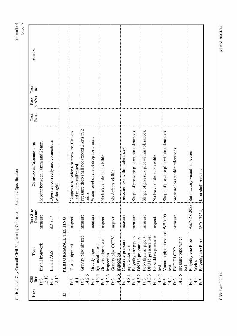
Chr
istc
hurc
h C
ity C
ounc
il C
ivil
Eng
inee
ring
Con
stru
ctio
n S
tand
ard
Spe
cifi
catio
n
App
endi
x 4
She
et 7
CS
S: P
art 3
201
4 pr
inte
d 30
/04/
14
ITE
M
CSS
RE
F
TA
SK
T
ES
T S
TD
/ D
ESC
RIP
C
OM
PL
IAN
CE
RE
QU
IRE
ME
NT
S
TE
ST
FR
EQ
. P
AS
S
YE
S/N
O
TE
ST
BY
A
CT
ION
S
P
t 3
12.1
3 In
stal
l iro
nwor
k m
easu
re
Mor
tar
betw
een
10m
m a
nd 2
5mm
.
P
t 3
12.1
4 In
stal
l AG
S
SD
317
O
pera
tes
corr
ectl
y an
d co
nnec
tion
s w
ater
tigh
t.
13
PE
RF
OR
MA
NC
E T
ES
TIN
G
P
t 3
14.1
T
est e
quip
men
t in
spec
t G
auge
s re
ad tw
ice
test
pre
ssur
e. G
auge
s an
d m
eter
s ca
libr
ated
.
P
t 3
14.2
.5G
ravi
ty p
ipe
air
test
m
easu
re
Pre
ssur
e dr
op s
hall
not
exc
eed
2 kP
a in
2
min
s.
P
t 3
14.2
.4G
ravi
ty p
ipe
hydr
osta
tic
test
m
easu
re
Wat
er le
vel d
oes
not d
rop
for
5 m
ins
P
t 3
14.2
.3G
ravi
ty p
ipe
visu
al
insp
ecti
on
insp
ect
No
leak
s or
def
ects
vis
ible
.
P
t 3
14.2
.6G
ravi
ty p
ipe
CC
TV
in
spec
tion
in
spec
t N
o de
fect
s vi
sibl
e.
P
t 3
14.3
.1C
oncr
ete
pres
sure
pi
pe w
ater
test
m
easu
re
pres
sure
loss
wit
hin
tole
ranc
es.
P
t 3
14.3
.2P
olye
thyl
ene
pipe
<
DN
315
pres
sure
test
m
easu
re
Sha
pe o
f pr
essu
re p
lot w
ithi
n to
lera
nces
.
P
t 3
14.3
.3P
olye
thyl
ene
pipe
>
DN
315
pres
sure
test
m
easu
re
Sha
pe o
f pr
essu
re p
lot w
ithi
n to
lera
nces
.
P
t 3
14.3
.4E
F s
addl
es p
ress
ure
test
in
spec
t N
o le
aks
or d
efec
ts v
isib
le.
P
t 3
14.4
V
acuu
m p
ipe
pres
sure
te
st
WS
A 0
6 S
hape
of
pres
sure
plo
t wit
hin
tole
ranc
es.
P
t 3
14.3
.5P
VC
DI
GR
P
pres
sure
pip
e w
ater
te
st
mea
sure
pr
essu
re lo
ss w
ithi
n to
lera
nces
P
t 3
14.5
P
olye
thyl
ene
Pip
e W
elds
A
S/N
ZS
203
3S
atis
fact
ory
visu
al in
spec
tion
P
t 3
Pol
yeth
ylen
e P
ipe
ISO
139
54,
Join
t sha
ll p
ass
test
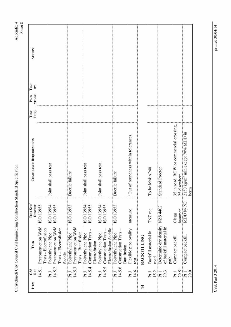
Chr
istc
hurc
h C
ity C
ounc
il C
ivil
Eng
inee
ring
Con
stru
ctio
n S
tand
ard
Spe
cifi
catio
n
App
endi
x 4
She
et 8
CS
S: P
art 3
201
4 pr
inte
d 30
/04/
14
ITE
M
CSS
RE
F
TA
SK
T
ES
T S
TD
/ D
ESC
RIP
C
OM
PL
IAN
CE
RE
QU
IRE
ME
NT
S
TE
ST
FR
EQ
. P
AS
S
YE
S/N
O
TE
ST
BY
A
CT
ION
S
14.5
.1P
reco
nstr
ucti
on W
eld
Tes
ts -
Ele
ctro
fusi
on
ISO
139
55
P
t 3
14.5
.2P
olye
thyl
ene
Pip
e P
reco
nstr
ucti
on W
eld
Tes
ts –
Ele
ctro
fusi
on
Sad
dle
ISO
139
54,
ISO
139
55
Join
t sha
ll p
ass
test
P
t 3
14.5
.3P
olye
thyl
ene
Pip
e P
reco
nstr
ucti
on W
eld
Tes
ts –
But
t fus
ion
ISO
139
53
Duc
tile
fai
lure
P
t 3
14.5
.4P
olye
thyl
ene
Pip
e C
onst
ruct
ion
Tes
ts -
E
lect
rofu
sion
ISO
139
54,
ISO
139
55
Join
t sha
ll p
ass
test
P
t 3
14.5
.5P
olye
thyl
ene
Pip
e C
onst
ruct
ion
Tes
ts –
E
lect
rofu
sion
Sad
dle
ISO
139
54,
ISO
139
55
Join
t sha
ll p
ass
test
P
t 3
14.5
.6P
olye
thyl
ene
Pip
e C
onst
ruct
ion
Tes
ts –
B
utt f
usio
n
ISO
139
53
Duc
tile
fai
lure
P
t 3
14.6
F
lexi
ble
pipe
ova
lity
te
st
mea
sure
‘O
ut o
f ro
undn
ess
wit
hin
tole
ranc
es.
14
BA
CK
FIL
LIN
G
P
t 3
15.2
B
ackf
ill m
ater
ial i
n ro
ad
TN
Z r
eq
To
be M
/4:A
P40
P
t 1
29.3
D
eter
min
e dr
y de
nsit
y of
bac
kfil
l mat
eria
l in
path
NZ
S 4
402
Sta
ndar
d P
roct
or
P
t 1
29.5
.1C
ompa
ct b
ackf
ill
Cle
gg
ham
mer
35
in r
oad,
RO
W o
r co
mm
erci
al c
ross
ing,
25
els
ewhe
re
P
t 1
29.0
C
ompa
ct b
ackf
ill
MD
D b
y N
D
2150
kg/
m3 m
in e
xcep
t 70%
MD
D in
be
rm
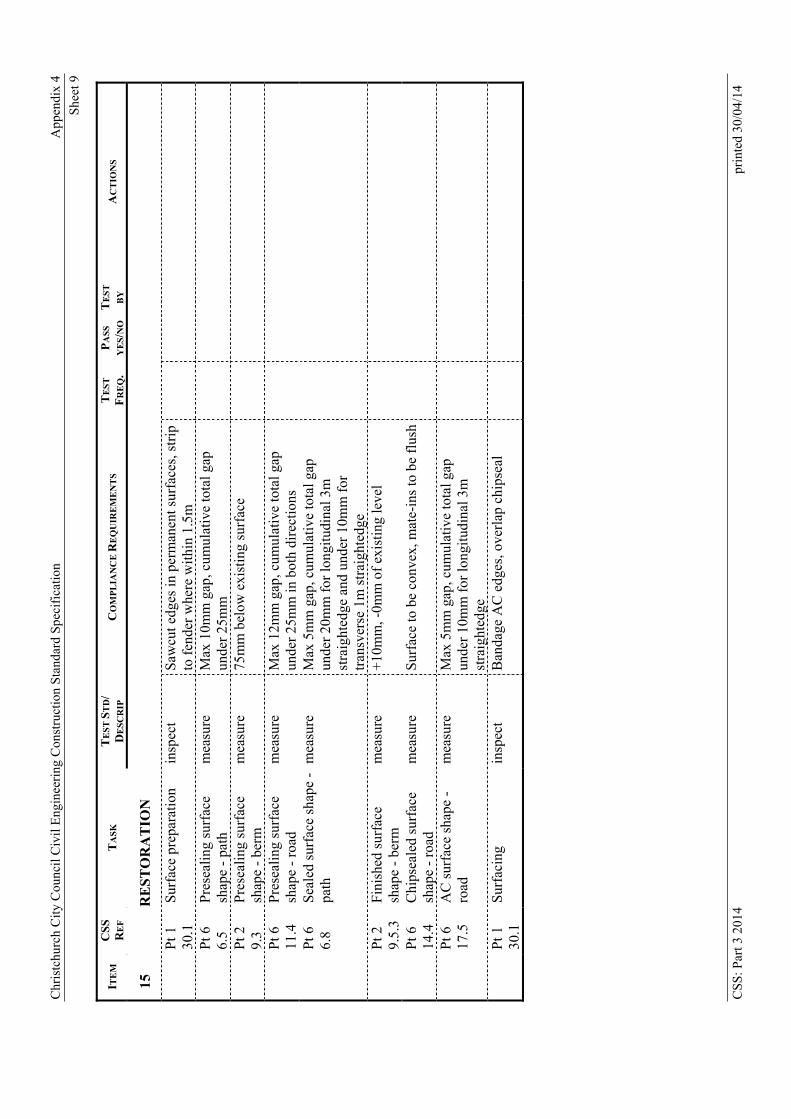
Chr
istc
hurc
h C
ity C
ounc
il C
ivil
Eng
inee
ring
Con
stru
ctio
n S
tand
ard
Spe
cifi
catio
n
App
endi
x 4
She
et 9
CS
S: P
art 3
201
4 pr
inte
d 30
/04/
14
ITE
M
CSS
RE
F
TA
SK
T
ES
T S
TD
/ D
ESC
RIP
C
OM
PL
IAN
CE
RE
QU
IRE
ME
NT
S
TE
ST
FR
EQ
. P
AS
S
YE
S/N
O
TE
ST
BY
A
CT
ION
S
15
RE
ST
OR
AT
ION
P
t 30
.1
1
S
urfa
ce p
repa
rati
on
insp
ect
Saw
cut e
dges
in p
erm
anen
t sur
face
s, s
trip
to
fen
der
whe
re w
ithi
n 1.
5m
P
t 6.
5 6
P
rese
alin
g su
rfac
e sh
ape
- pa
th
mea
sure
M
ax 1
0mm
gap
, cum
ulat
ive
tota
l gap
un
der
25m
m
P
t 9.
3 2 P
rese
alin
g su
rfac
e sh
ape
- be
rm
mea
sure
75
mm
bel
ow e
xist
ing
surf
ace
P
t 11
.4
6
P
rese
alin
g su
rfac
e sh
ape
- ro
ad
mea
sure
M
ax 1
2mm
gap
, cum
ulat
ive
tota
l gap
un
der
25m
m in
bot
h di
rect
ions
P
t 6.
8 6
S
eale
d su
rfac
e sh
ape
- pa
th
mea
sure
M
ax 5
mm
gap
, cum
ulat
ive
tota
l gap
un
der
20m
m f
or lo
ngit
udin
al 3
m
stra
ight
edge
and
und
er 1
0mm
for
tr
ansv
erse
1m
str
aigh
tedg
e
P
t 29.
5.3
Fin
ishe
d su
rfac
e sh
ape
- be
rm
mea
sure
+
10m
m, -
0mm
of
exis
ting
leve
l
P
t 14
.4
6 C
hips
eale
d su
rfac
e sh
ape
- ro
ad
mea
sure
S
urfa
ce to
be
conv
ex, m
ate-
ins
to b
e fl
ush
P
t 17
.5
6
A
C s
urfa
ce s
hape
-
road
m
easu
re
Max
5m
m g
ap, c
umul
ativ
e to
tal g
ap
unde
r 10
mm
for
long
itud
inal
3m
st
raig
hted
ge
P
t 30
.1
1 S
urfa
cing
in
spec
t B
anda
ge A
C e
dges
, ove
rlap
chi
psea
l
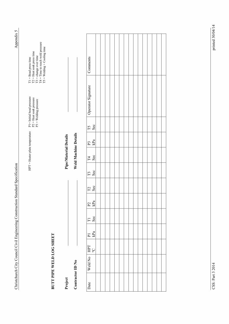
Chr
istc
hurc
h C
ity C
ounc
il C
ivil
Eng
inee
ring
Con
stru
ctio
n S
tand
ard
Spe
cifi
catio
n A
ppen
dix
5
HP
T =
Hea
ter
plat
e te
mpe
ratu
re
P1=
Ini
tial
bea
d pr
essu
re
P2
= H
eat s
oak
pres
sure
P
3 =
Wel
ding
pre
ssur
e
T1
= B
ead
pres
s ti
me
T2
= H
eat s
oak
pres
s ti
me
T3
= c
hang
e ov
er ti
me
T4
= T
ime
to r
each
wel
d pr
essu
re
T5
= W
eldi
ng +
Coo
ling
tim
e
BU
TT
PIP
E W
EL
D L
OG
SH
EE
T
Pro
ject
P
ipe/
Mat
eria
l Det
ails
C
ontr
acto
r ID
No
Wel
d M
ach
ine
Det
ails
D
ate
Wel
d N
o H
PT
ºC
P
1 kP
a T
1 S
ec
P2
kPa
T2
Sec
T
3 S
ec
T4
Sec
P
3 kP
a T
5 S
ec
Ope
rato
r S
igna
ture
C
omm
ents
CS
S: P
art 3
201
4 pr
inte
d 30
/04/
14
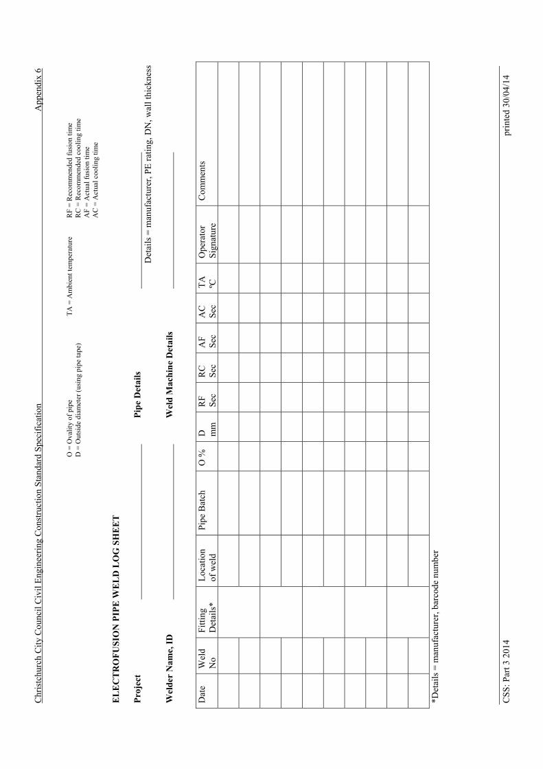
Chr
istc
hurc
h C
ity C
ounc
il C
ivil
Eng
inee
ring
Con
stru
ctio
n S
tand
ard
Spe
cifi
catio
n A
ppen
dix
6
O =
Ova
lity
of
pipe
D
= O
utsi
de d
iam
eter
(us
ing
pipe
tape
) T
A =
Am
bien
t tem
pera
ture
RF
= R
ecom
men
ded
fusi
on ti
me
RC
= R
ecom
men
ded
cool
ing
tim
e A
F =
Act
ual f
usio
n ti
me
AC
= A
ctua
l coo
ling
tim
e
EL
EC
TR
OF
US
ION
PIP
E W
EL
D L
OG
SH
EE
T
Pro
ject
P
ipe
Det
ails
Det
ails
= m
anuf
actu
rer,
PE
rat
ing,
DN
, wal
l thi
ckne
ss
Wel
der
Nam
e, I
D
Wel
d M
ach
ine
Det
ails
D
ate
Wel
d N
o F
ittin
g D
etai
ls*
Loc
atio
n of
wel
d P
ipe
Bat
ch
O %
D
m
m
RF
S
ec
RC
S
ec
AF
S
ec
AC
S
ec
TA
ºC
O
pera
tor
Sig
natu
re
Com
men
ts
*Det
ails
= m
anuf
actu
rer,
bar
code
num
ber
CS
S: P
art 3
201
4 pr
inte
d 30
/04/
14

Christchurch City Council Civil Engineering Construction Standard Specification
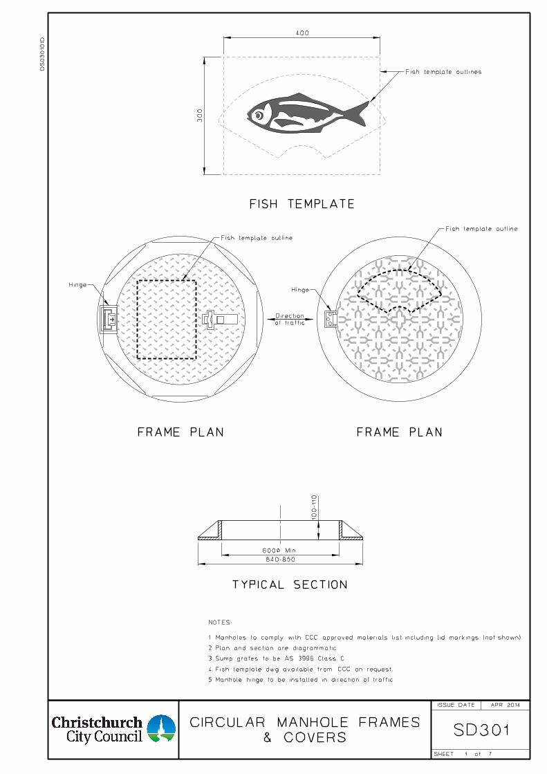
1
SD301
NOTES:
FRAME PLAN
7
& COVERS
CIRCULAR MANHOLE FRAMES
APR 2014
DS
030
10
1D
600< Min.
840-850
100-110
TYPICAL SECTION
FRAME PLAN
Fish template outline
Hinge
Fish template outlines
of traffic
Direction
Fish template outline
Hinge
2. Plan and section are diagrammatic.
5. Manhole hinge to be installed in direction of traffic.
3. Sump grates to be AS 3996 Class C.
FISH TEMPLATE
4. Fish template dwg available from CCC on request.
1. Manholes to comply with CCC approved materials list including lid markings (not shown).
ISSUE DATE
SHEET of
400
300
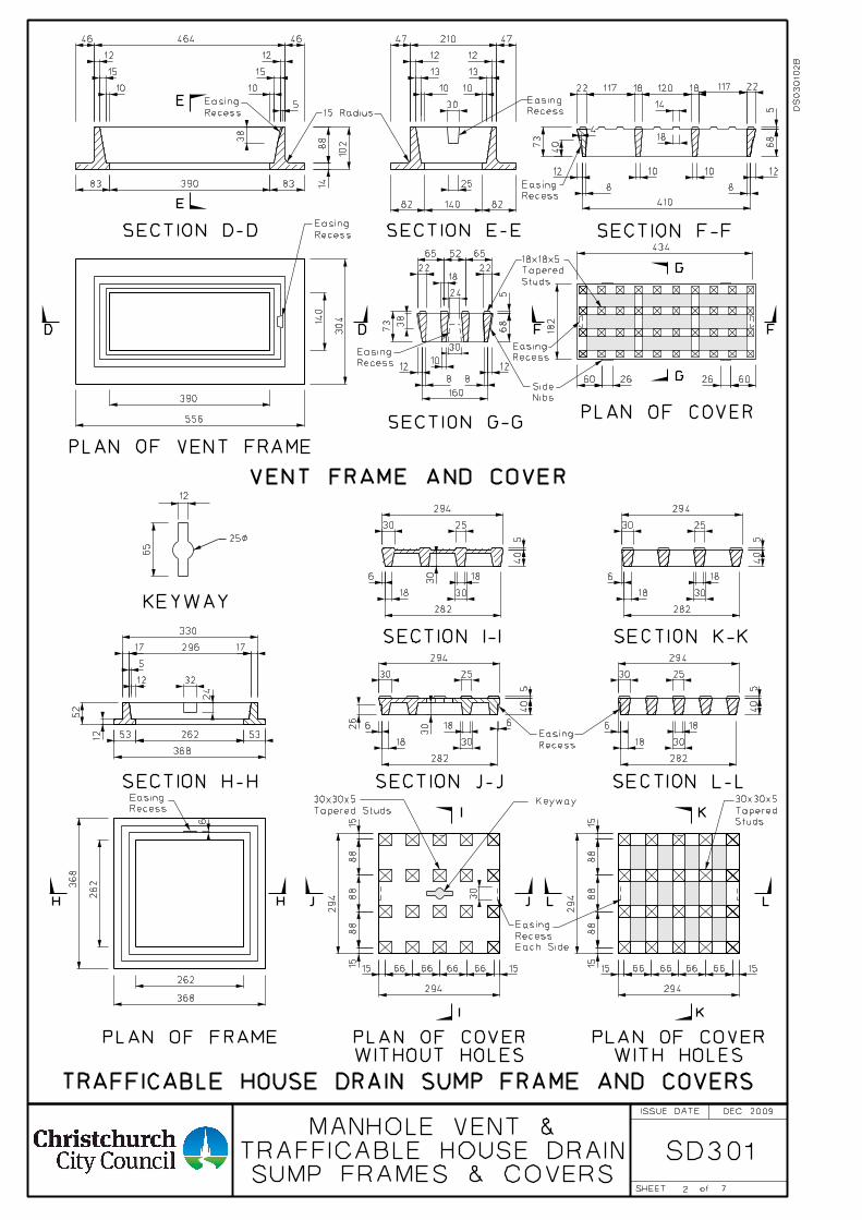
SD301
2
65
12
25<
KEYWAY
262
368
262
Recess
Easing
368
53 53
330
32
24
17
5
17
12
52
540
25
30
186
18
282
30
294
294
294
540
25
30
186
18
282
30
294
15 66 66 66 66 15
1515
88
88
88
H H
SECTION H-H
PLAN OF FRAME
18 18
568
73
12
8
12
8
SECTION F-F
182
PLAN OF COVER
FF
12 12
15
10
15
10
46 464 46 47 210 47
12 12
13
10
13
10
8214082
10288
14
390
556
140
304
SECTION D-D SECTION E-E
30
25
5
38
Recess
Easing
PLAN OF VENT FRAME
83 390 83
D D
VENT FRAME AND COVER
SECTION L-L
SECTION K-K
WITH HOLESPLAN OF COVER
K
K
LL
540
25
30
186
18
282
30
294
294
294
540
25
30
186
18
282
30
294
15 66 66 66 66 15
1515
88
88
88
I
I
JJ
Keyway
30
Recess
Easing
SECTION J-J
SECTION I-I
Tapered Studs
30x30x5
Studs
Tapered
30x30x5
3026
30
Each Side
Recess
Easing
434
10 10
410
22 117 120 117 22
14
18
568
73
12
8
12
8
10
160
22 22
65 52 65
18Studs
Tapered
18x18x5
38
G
G
SECTION G-G
60 26
Nibs
Side6026
Recess
Easing
Recess
Easing
15 Radius
40
4
30
24
Recess
Easing
Recess
Easing
Recess
Easing
E
E
WITHOUT HOLESPLAN OF COVER
TRAFFICABLE HOUSE DRAIN SUMP FRAME AND COVERS
296
12
262
368
6
6
SUMP FRAMES & COVERSTRAFFICABLE HOUSE DRAIN
MANHOLE VENT &
DS
030
10
2B
7
DEC 2009ISSUE DATE
SHEET of
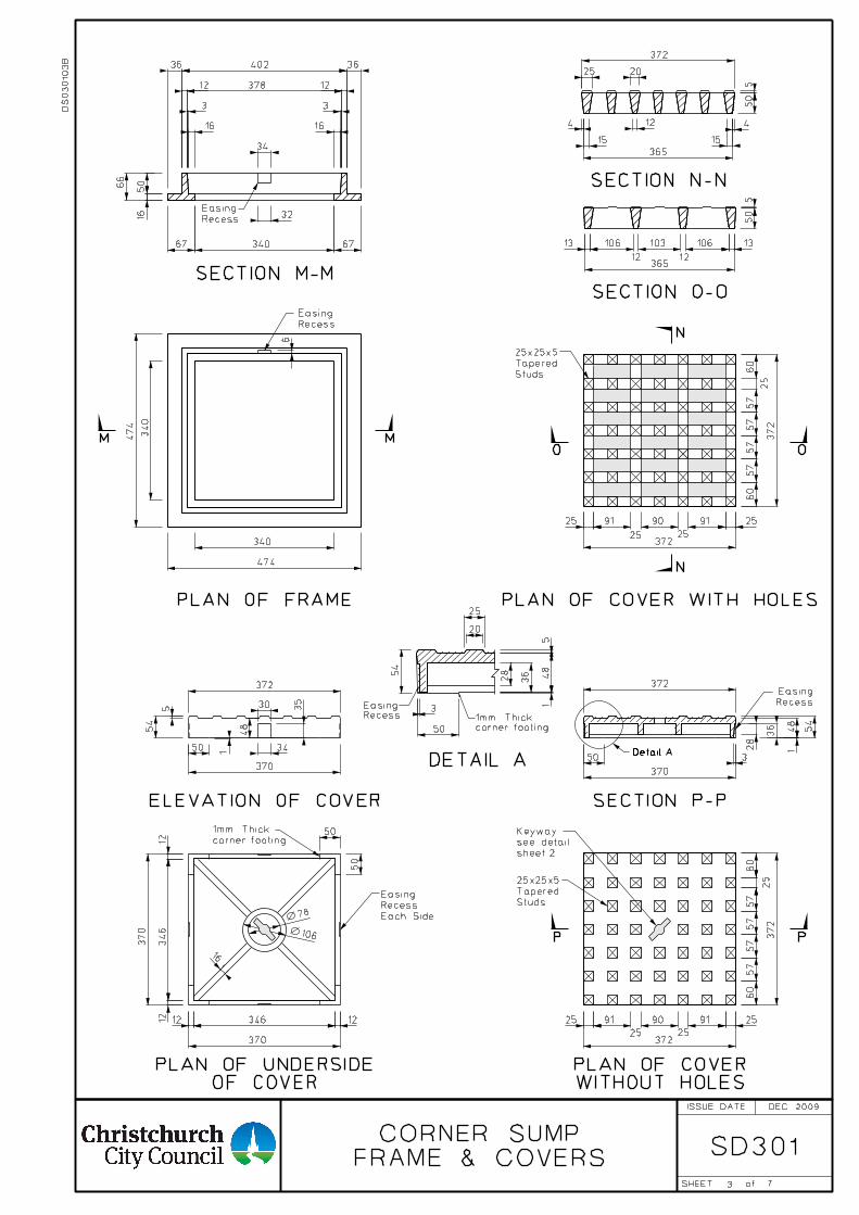
3
SD301
372
372
60
60
57
57
57
57
25 91 90 91 25
25 25370
34612 12
78
50
50
370
346
1212
106
16
372
370
50
372
370
48
5
54
150
30
34
35
Recess
Easing
PLAN OF FRAME
34
16
3
36
16
36402
165066
32
67 340 67
12 12
3
SECTION M-M
474
340
474
340
378
372
372
365
13 106 103 106 13
12 12
50
60
57
57
57
57
5
M
25 91 90 91 25
25 25
365
50
372
4 12
20
4
5
M
36
28
48
54
1
O O
N
SECTION N-N
SECTION O-O
SECTION P-P
P P
N
3
PLAN OF COVER WITH HOLES
Recess
Easing
OF COVERPLAN OF UNDERSIDE
Recess
Easing
ELEVATION OF COVER
Each Side
Recess
Easing
sheet 2
see detail
Keywaycorner footing
1mm Thick
Detail A
25
1515
25
Studs
Tapered
25x25x5
Studs
Tapered
25x25x5 25
6
WITHOUT HOLESPLAN OF COVER
RecessEasing
corner footing1mm Thick
DETAIL A
25
20
548
36
28
1
3
50
54
60
FRAME & COVERS
CORNER SUMP
DS
030
10
3B
7
DEC 2009ISSUE DATE
SHEET of
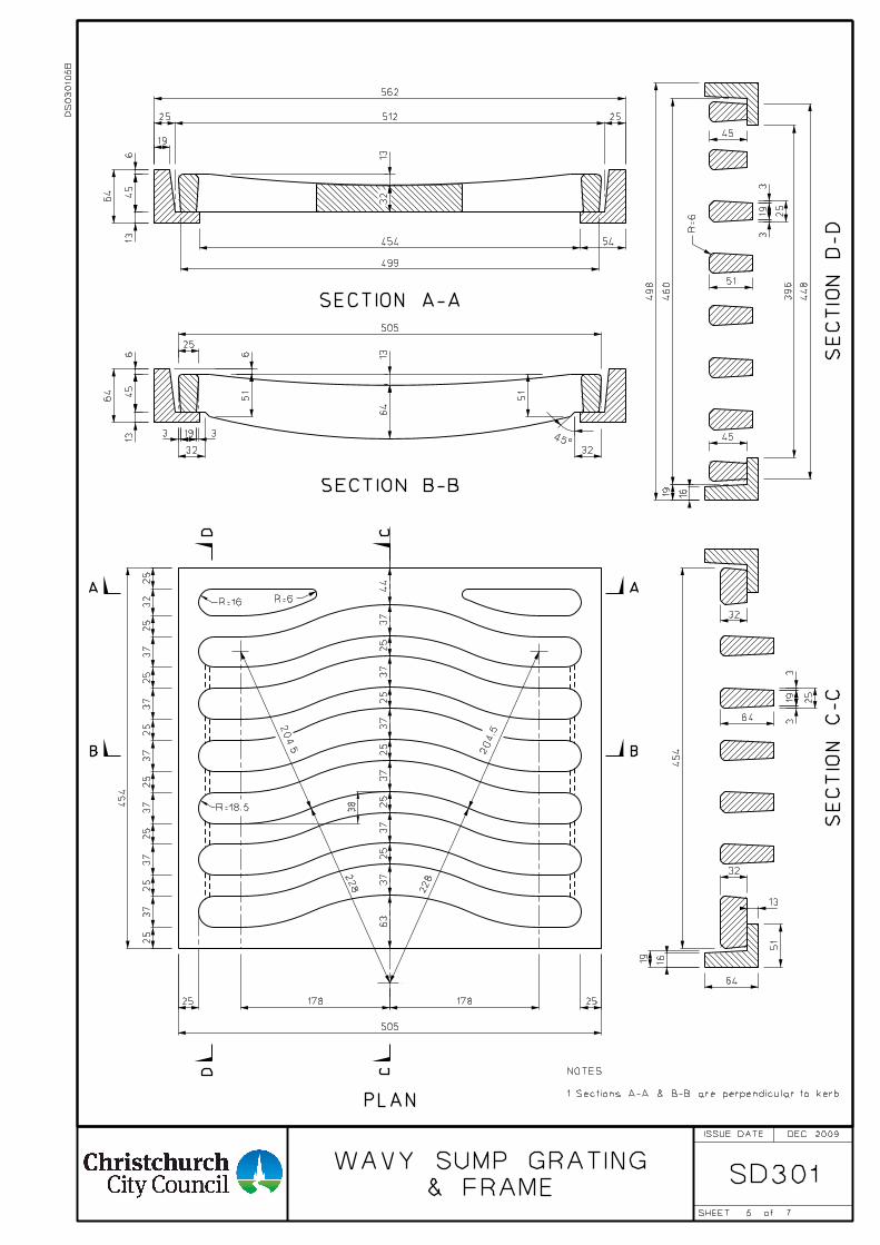
5
SD301
505
178 17825 25
B
AR=6R=16
454
25
32
25
37
25
37
25
37
25
37
25
37
25
37
25
B
A44
37
25
37
25
37
25
37
25
37
25
37
63
38
51
6
64
13
32
45
13
64
6
51
25
193 3
32
13
45
13
64
6
499
54454
19
2551225
562
32
204.5
228
228
204.5
CD
CD
45°
19
45
45
498
460
16
396
448
13
64
19 16
R=6
51
193
3
25
193
3
25
32
64
32
51
SECTION B-B
SECTION A-A
SE
CTIO
N
D-
DS
EC
TIO
N
C-C
PLAN
505
454
R=18.5
DS
030
105
B
7
DEC 2009
NOTES
1. Sections A-A & B-B are perpendicular to kerb.
& FRAME
WAVY SUMP GRATING
ISSUE DATE
SHEET of
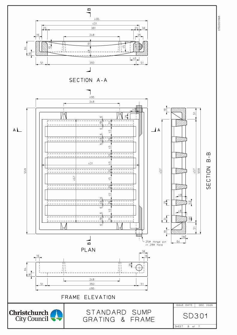
6
SD301GRATING & FRAME
STANDARD SUMP
A
1948
382538125
495
40
5139351
64
16
16 35
45
248
31
45
25
45
25
45
25
45
25
45
25
45
31
619
66
136
619
66
136
248
495
5139351
38
25
431
64
16
16
13
48
31
19
48
19
16
64
51
457
51
559
25
457
559
495
248
A
B
PLAN
SECTION A-A
SE
CTIO
N
B-B
25
40
in 28< hole
25< Hinge pin
FRAME ELEVATION
B
19
16
431
457
10
7
DS
030
10
6B
DEC 2009ISSUE DATE
SHEET of
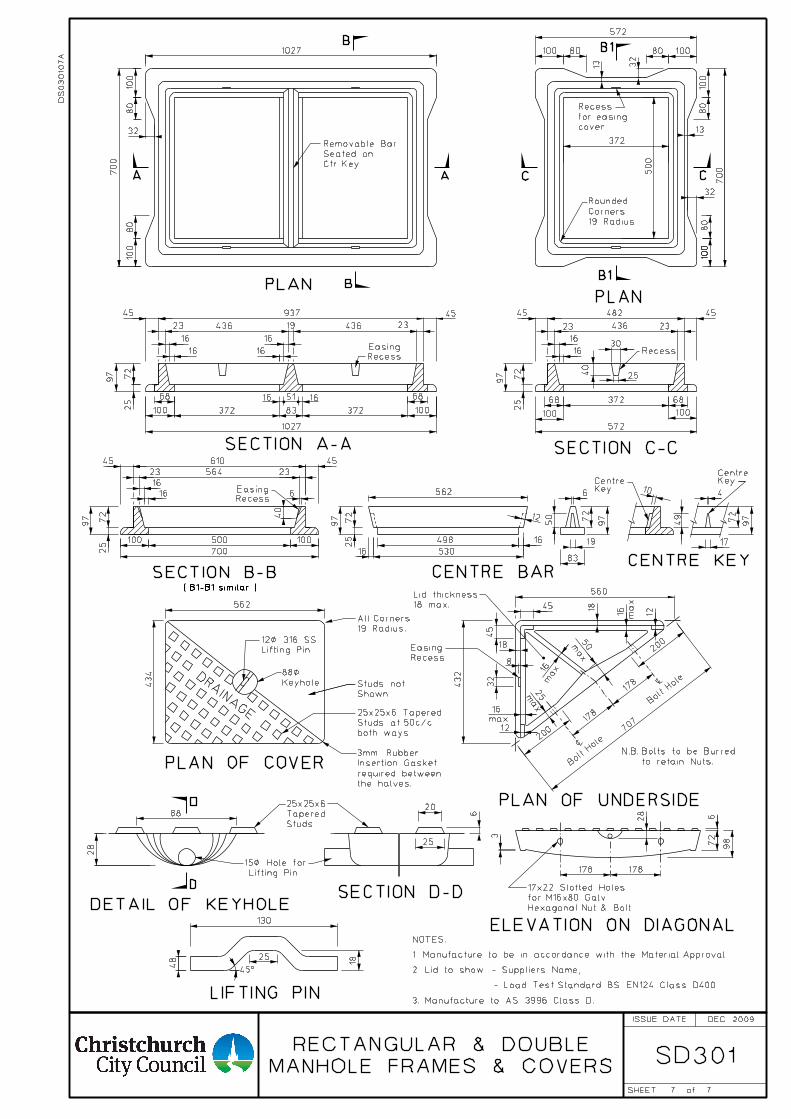
SD301
DRAIN
AGE
80
19 Radius
Corners
Rounded
68
72
500100 100
700
18
13
13
Recess
19 Radius.
All Corners
Shown.
Studs not
Bolt
Hole
$
Bolt
Hole
$
to retain Nuts.
N.B. Bolts to be Burred
PLAN
SECTION A-A SECTION C-C
CENTRE BAR
PLAN OF COVER
ELEVATION ON DIAGONAL
CCAA
B
BB1
19
3562
Keyhole
88<
Recess
Easing
432
80
937
23
16
16
45
72
25
97
45 482
23
16
16
100 100
572
45 610
23
16
16
19 436
97
45
83
72
97
50
6
16
53016
498
45
45
560
200
178
178
200 70
7
PLAN OF UNDERSIDE
Lifting Pin
12< 316 SS
16 max
32
8
30
83100 372 100372
1027
51
16
16
436
45
23
45
23436
40
25
23564
25
72
100100
100
572
the halves.
required between
Insertion Gasket
3mm Rubber
434
562
97
25
72
LIFTING PIN
SECTION D-DDETAIL OF KEYHOLE
D
DLifting Pin.
15< Hole for
45°
88
18
25
130
6
98
178178
PLAN
NOTES:
28
50max
25max
97
25
72
12
16 16 68 3726868
Ctr. Key
Seated on
Removable Bar
B1
SECTION B-B ( B1-B1 similar )
6
12
18
16
max
16max
1272
97
49
4
17
10
CENTRE KEY
KeyCentre Key
Centre
18 max.
Lid thickness
Hexagonal Nut & Bolt.
for M16x80 Galv.
17x22 Slotted Holes
cover.
for easing
Recess
100
80
32
32
100
80
700500
372
1027
700
80
100
80
100
32
48
28
40
both ways.
Studs at 50c/c
25x25x6 Tapered
Studs
Tapered
25x25x6
6
20
25
RecessEasing
RecessEasing
DS
030
10
7A
77
MANHOLE FRAMES & COVERS
RECTANGULAR & DOUBLE
DEC 2009
1. Manufacture to be in accordance with the Material Approval.
2. Lid to show - Suppliers Name,
- Load Test Standard BS EN124 Class D400.
3. Manufacture to AS 3996 Class D.
ISSUE DATE
SHEET of
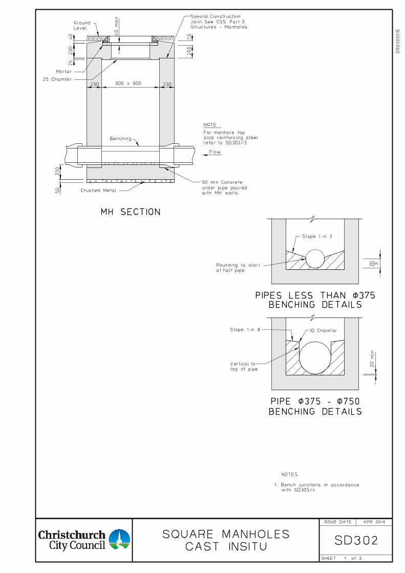
1
SD302CAST INSITU
SQUARE MANHOLES
Slope 1 in 3
at half pipe.
Rounding to start 2D
Slope 1 in 8 10 Chamfer
top of pipe
Vertical to 20
min
BENCHING DETAILSPIPES LESS THAN <375
3
BENCHING DETAILS
PIPE <375 - <750
APR 2014
DS
030
20
1E
with SD303/4.
1. Bench junctions in accordance
NOTES:
25 Chamfer
with MH walls.
under pipe poured
50 min. Concrete
Crushed Metal.
Mortar
Level.
Ground
Benching
200
900 x 900230
230
50
704
0
max
Flow
refer to SD302/3.
slab reinforcing steel
For manhole top
NOTE :
230
MH SECTION
Structures - Manholes
Joint. See CSS Part 3
Special Construction
40
230
25
ISSUE DATE
SHEET of
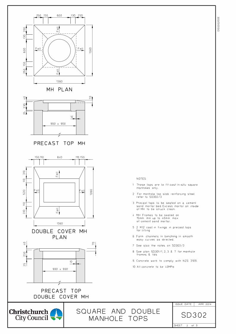
2
SD302
900 x 900
Fall
Fall
FallFall
3
70
1360
1360
250
130
600
130
250
250130600130250
40
230
25
10
150110 840 110 150
310
110
520
110
310
DOUBLE COVER MH
PRECAST TOP
1360
1360
10
900 x 900
FallFall
Fall
Fall
PLAN
DOUBLE COVER MH
70
230
25
40
MANHOLE TOPS
SQUARE AND DOUBLE
NOTES:
refer to SD302/3.
sand mortar bed. Excess mortar on inside
of MH to be struck clean.
15mm min. up to 40mm max.
of cement sand mortar.
for lifting.
easy curves as directed.
frames & lids.
APR 2014
MH PLAN
PRECAST TOP MH
manholes only.
1. These tops are to fit cast in-situ square
2. For manhole top slab reinforcing steel
3. Precast tops to be seated on a cement
4. MH Frames to be seated on
5. 2 M12 cast in fixings in precast tops
6. Form channels in benching in smooth
7. See also the notes on SD303/3.
8. See plan SD301/1, 2, 3 & 7 for manhole
9. Concrete work to comply with NZS 3109.
10. All concrete to be 40MPa.
DS
030
20
2E
ISSUE DATE
SHEET of
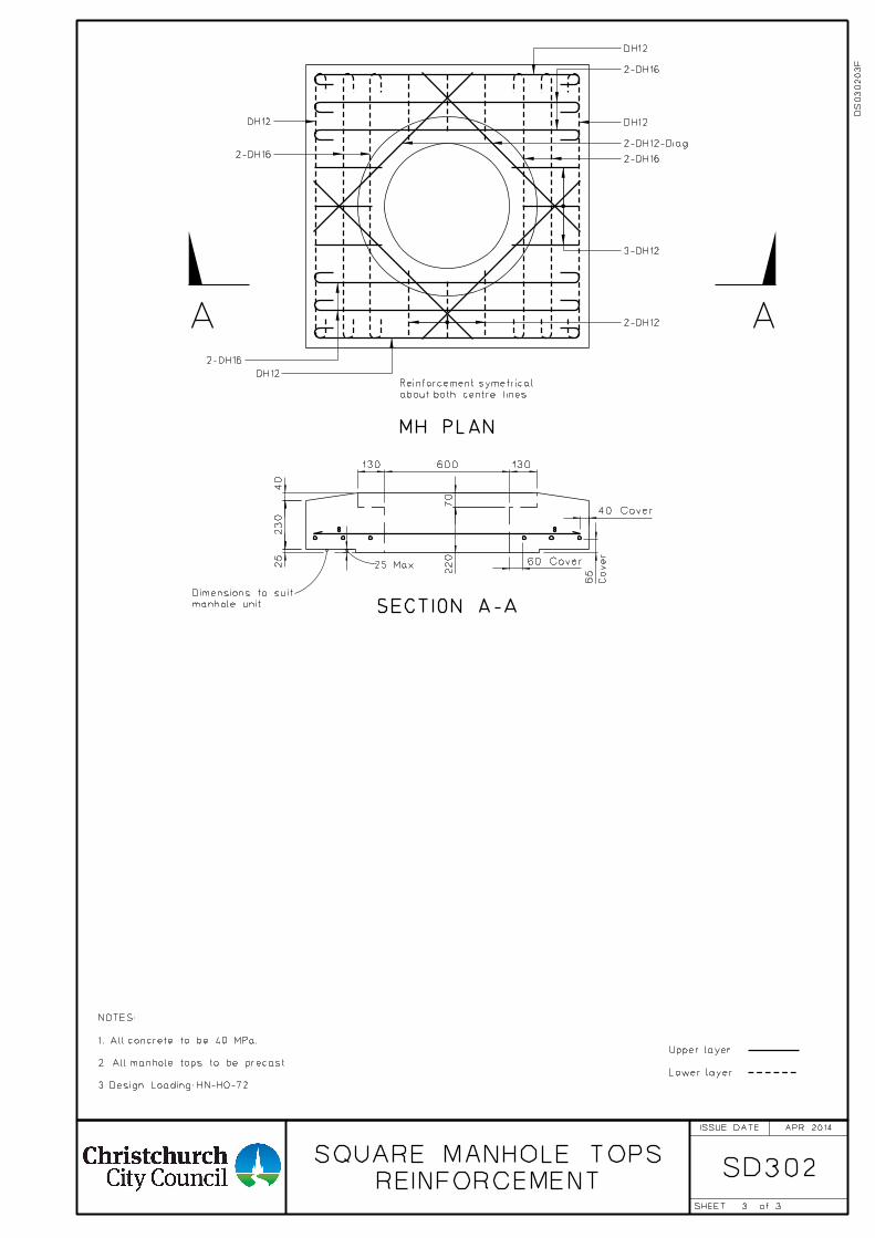
SD302
3
REINFORCEMENT
SQUARE MANHOLE TOPS
about both centre lines
Reinforcement symetrical
Lower layer
Upper layer
65
Cover
manhole unit
Dimensions to suit
A A
SECTION A-A
25 Max
3
3. Design Loading: HN-HO-72
2. All manhole tops to be precast.
1. All concrete to be 40 MPa.
NOTES:
60 Cover
40 Cover
70
220
130600130
40
230
25
DH12
2-DH16
2-DH16
DH12
APR 2014
DS
030
20
3F
MH PLAN
DH12
2-DH12-Diag
2-DH16
2-DH16
DH12
3-DH12
2-DH12
ISSUE DATE
SHEET of
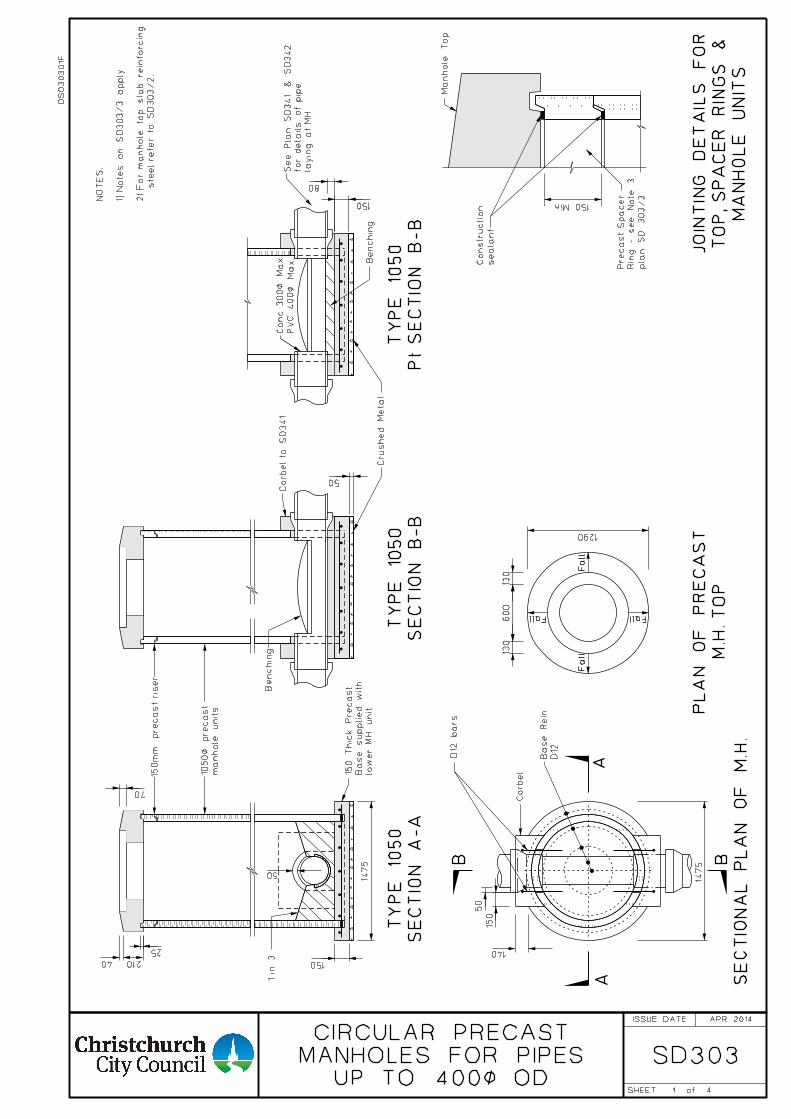
1
SD303
SE
CTIO
NA
L P
LA
N
OF
M.H.
M.H. T
OP
PL
AN
OF
PR
EC
AS
T
1 in 3
AA
B
D12
Base
Rein.
Corbel
1475
140
50
150
low
er
MH unit.
Base supplied
with
150
Thic
k Precast
SE
CTIO
N
A-
A
TY
PE 10
50
SE
CTIO
N
B-B
TY
PE 10
50
Pt
SE
CTIO
N
B-B
TY
PE 10
50
Benchin
g
Crushed
Metal
150
50
1475
150
50
Fall
Fall
FallFall
Benchin
g
B
manhole units
1050< precast
MA
NH
OL
E
UNIT
S
TO
P, S
PA
CE
R
RIN
GS
&
JOIN
TIN
G
DE
TAIL
S
FO
R
pla
n S
D 303/3
Rin
g - see
Note 3
Precast
Spacer
Manhole
Top
UP TO 400< OD
MANHOLES FOR PIPES
CIRCULAR PRECAST
210
25
70
40
Corbel to S
D341
4
NO
TE
S:
1) N
ote
s on S
D303/3 apply.
2) For m
anhole to
p sla
b reinforcin
g
ste
el refer to S
D303/2.
PV
C 400<
Max.
Conc. 300<
Max.
layin
g at
MH.
for details of pip
e
See Pla
n S
D341 &
SD342
seala
nt
Constr
uction
APR 2014
150 Min
600
130
130
1290
D12 bars
150
mm
precast ris
er
DS
030
30
1F
80
ISSUE DATE
SHEET of
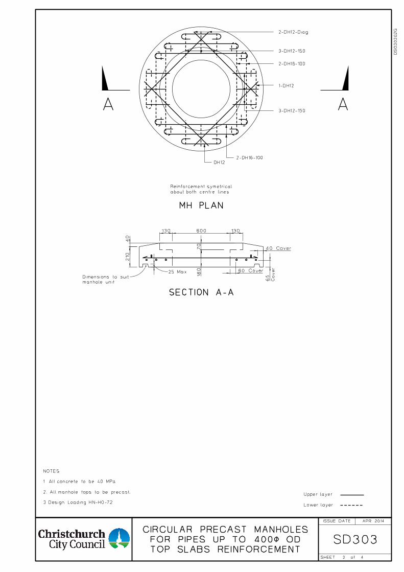
2
SD303TOP SLABS REINFORCEMENT
FOR PIPES UP TO 400< OD
CIRCULAR PRECAST MANHOLES
about both centre lines
Reinforcement symetrical
Lower layer
Upper layer
130600130
60 Cover
40 Cover
65
Cover
manhole unit
Dimensions to suit
A A
SECTION A-A
25 Max
3. Design Loading: HN-HO-72
2. All manhole tops to be precast.
1. All concrete to be 40 MPa.
NOTES:
210
40
70
180
4
2-DH12-Diag
3-DH12-150
2-DH16-100
1-DH12
3-DH12-150
DH122-DH16-100
APR 2014
DS
030
30
2G
MH PLAN
ISSUE DATE
SHEET of
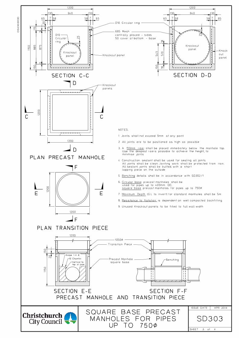
F
1200
1200
1050<
1150
150
Transition Piece
square base
Precast Manhole
E
F
E
PRECAST MANHOLE AND TRANSITION PIECE
SECTION E-E SECTION F-F
1200
PLAN TRANSITION PIECE
65 587 6558 7
ring
Circular
D10
50 cover at bottom - base
centrally placed - sides
665 Mesh
D10 Circular ring
SECTION C-C SECTION D-D
C C
D
D
PLAN PRECAST MANHOLE
65 587 6558 7
Knockout panelpanel
Knockout
panel
Knockout
panel
out
Knock
panels
Knockout
115
5
20
1200
130 940
25
130
1150
875
885
150
5
20
510
150
545
25
1200
130 130940
1200
1200
1818
3 UP TO 750<
MANHOLES FOR PIPESSQUARE BASE PRECAST
4
SD303
10 Chamfer
Slope 1 in 8
top of pipe
Vertical toBenching
APR 2014
DS
030
30
3D
9. Unused Knockout panels to be filled to full wall width.
8. Resistance to flotation is dependent on well compacted backfilling.
7. Maximum Depth (G.L. to invert) for standard manholes shall be 5m.
square base precast manholes for pipes up to 750<.
used for pipes up to 400mm OD,
6. Circular base precast manholes shall be
5. Benching details shall be in accordance with SD302/1.
lapping piece on the outside.
All sealant joints shall be butted, with a short
All joints shall be clean. Jointing work shall be protected from rain.
4. Construction sealant shall be used for sealing all joints.
minimise joints.
Use the deepest risers possible to achieve the height, to
3. A 150mm riser shall be placed immediately below the manhole top.
2. All joints are to be positioned as high as possible.
1. Joints shall not exceed 5mm at any point.
NOTES:
ISSUE DATE
SHEET of
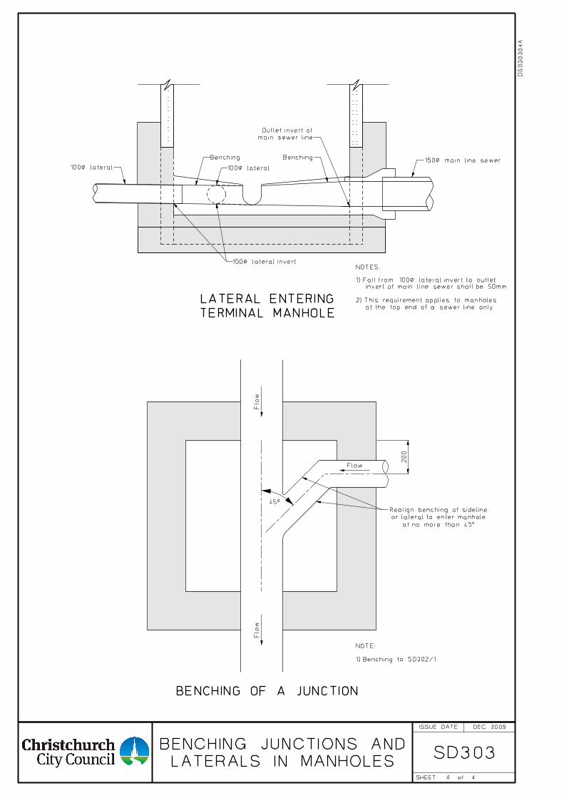
SD303
DEC 2009
44
NOTES:
Benching Benching
45°
at no more than 45°
or lateral to enter manhole
Realign benching of sideline
BENCHING OF A JUNCTION
200
Flo
wFlo
w
Flow
TERMINAL MANHOLE
LATERAL ENTERING
150< main line sewer
DS
030
30
4A
100< lateral 100< lateral
100< lateral invert
1) Fall from 100< lateral invert to outlet
invert of main line sewer shall be 50mm.
2) This requirement applies to manholes
at the top end of a sewer line only.
main sewer line
Outlet invert of
1) Benching to SD302/1
NOTE:
LATERALS IN MANHOLES
BENCHING JUNCTIONS AND
ISSUE DATE
SHEET of
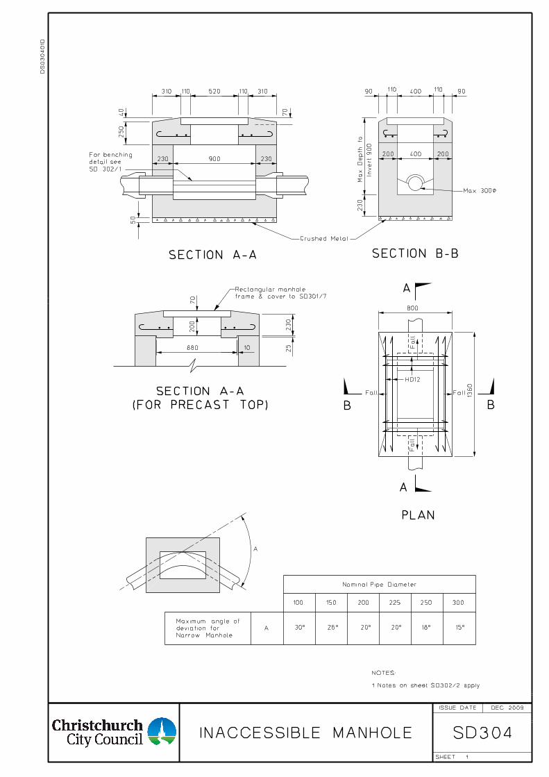
SD304
A
PLAN
Nominal Pipe Diameter
100 150 200 225 250 300
30° 26° 20° 20° 18° 15°
Narrow Manhole.
deviation for
Maximum angle of
A
Invert
900
Crushed Metal
A
A
BB
SECTION A-A SECTION B-B
(FOR PRECAST TOP)
SECTION A-A
400 9090
230
200 400 200
800
1360
230
25
70
880 10
Max
Depth to
110 110
Max 300<200
Fall Fall
Fall
Fall
310 110 520 110 310
250
230 900 230
50
SD 302/1
detail see
For benching
70
40
1
HD12
DS
030
40
1D
INACCESSIBLE MANHOLE
DEC 2009
frame & cover to SD301/7
Rectangular manhole
1. Notes on sheet SD302/2 apply.
NOTES:
ISSUE DATE
SHEET
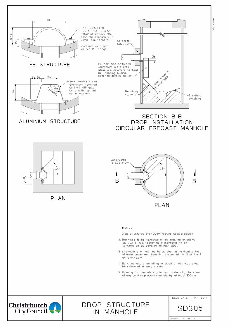
SD305
PLAN
PLAN
45°
CIRCULAR PRECAST MANHOLE
DROP INSTALLATION
SECTION B-B
1
DS
030
50
1D
APR 2014
of any joint in precast manhole by at least 300mm.
5. Opening for manhole starter and corbel shall be clear
be reformed in easy curves.
4. Benching and channelling in existing manholes shall
as applicable.
of main sewer and benching graded at 1 in 3 or 1 in 8
3. Channelling in new manholes shall be vertical to top
constructed as detailed on plan SD341.
SD 302 & 303. Pipelaying at manholes to be
2. Manholes to be constructed as detailed on plans
1. Drop structures over 225< require special design
IN MANHOLE
DROP STRUCTURE
SD341/2
Corbel to
50
channel depth
100m
m
Minim
um
slope 1:1
Benching
benching
Standard
Refer to details on left.
bolt spacing 600mm.
structure. Maximum vertical
aluminium plate drop
PE half pipe or folded
2
B B
45°
to SD341/2
Conc. Corbel
250
NOTES:
ISSUE DATE
SHEET of
157.5
315
35
welded PE flange
75x10mm extrusion
PE STRUCTURE
30mm dia. washers
concrete anchors with
Retained by No.4 M12
PE6 or PN8 PE pipe
Half DN315 PE100
1505050
150
108°
ALUMINIUM STRUCTURE
nylon washers
bolts with top hat
by No.4 M10 galv.
aluminium retained
3mm marine grade
Typically
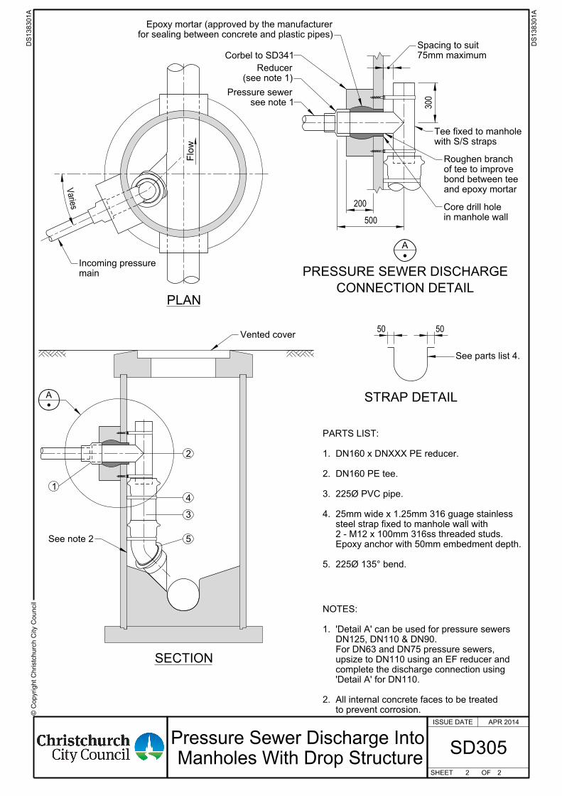
© C
opyright
Chr istc
hurc
h City C
ouncil
ISSUE DATE
SHEET OF
75mm maximum
Spacing to suit
and epoxy mortar
bond between tee
of tee to improve
Roughen branch
in manhole wall
Core drill hole
(see note 1)
Reducer
Corbel to SD341
for sealing between concrete and plastic pipes)
Epoxy mortar (approved by the manufacturer
see note 1
Pressure sewer
See parts list 4.
with S/S straps
Tee fixed to manhole
Vented cover
See note 2
main
Incoming pressure
5. 225Ø 135° bend.
Epoxy anchor with 50mm embedment depth.
2 - M12 x 100mm 316ss threaded studs.
steel strap fixed to manhole wall with
4. 25mm wide x 1.25mm 316 guage stainless
3. 225Ø PVC pipe.
2. DN160 PE tee.
1. DN160 x DNXXX PE reducer.
PARTS LIST:
to prevent corrosion.
2. All internal concrete faces to be treated
'Detail A' for DN110.
complete the discharge connection using
upsize to DN110 using an EF reducer and
For DN63 and DN75 pressure sewers,
DN125, DN110 & DN90.
1. 'Detail A' can be used for pressure sewers
NOTES:
2 2
DS138301
A
DS138301
A
SD305
APR 2014
Pressure Sewer Discharge Into
Manholes With Drop Structure
200
500
300
50 50
CONNECTION DETAIL
PRESSURE SEWER DISCHARGE
A
STRAP DETAIL
SECTION
Varies
Flo
w
A
PLAN
4
3
2
5
1
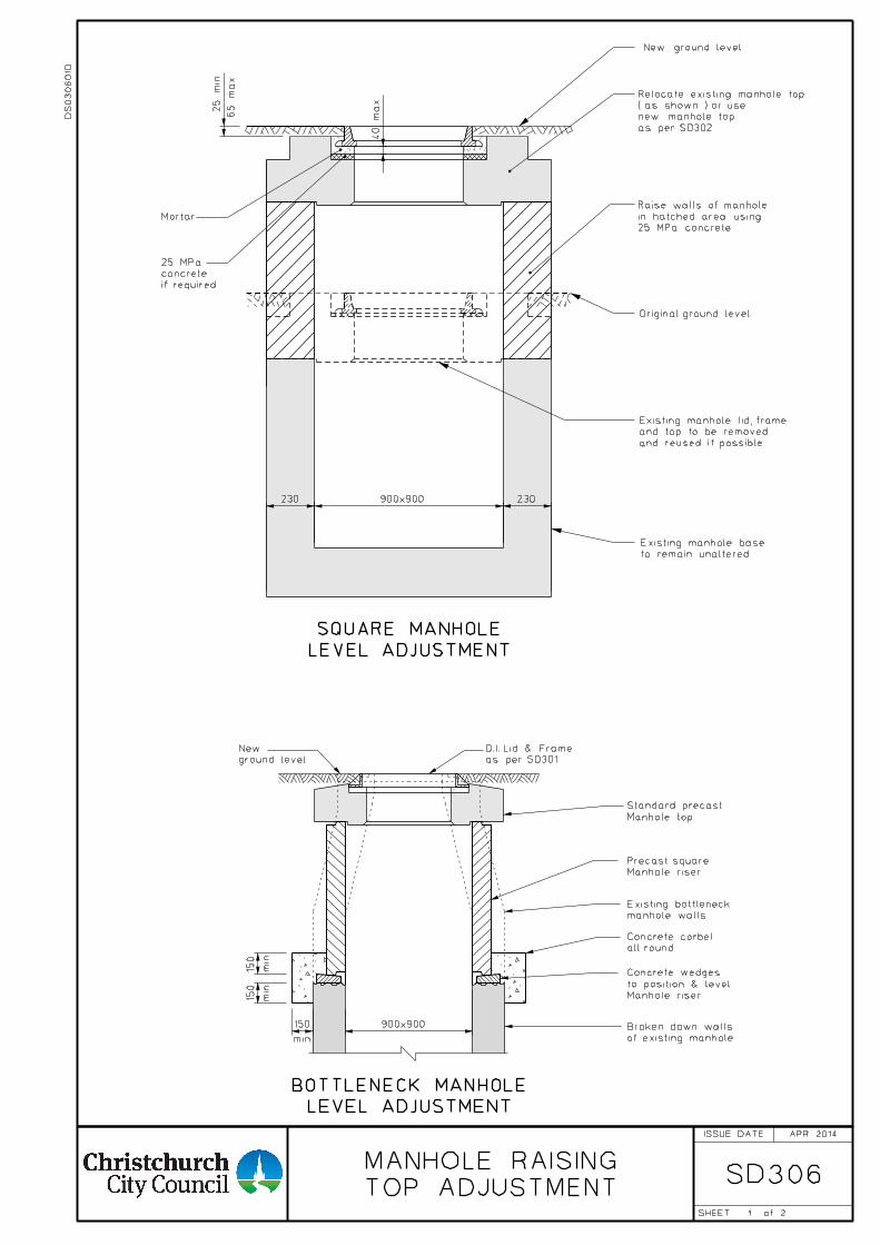
1
SD306TOP ADJUSTMENT
MANHOLE RAISING
min
min
min
Manhole top
Standard precast
Manhole riser
Precast square
manhole walls
Existing bottleneck
of existing manhole
Broken down walls
all round
Concrete corbel
Manhole riser
to position & level
Concrete wedges
ground level
New
LEVEL ADJUSTMENT
BOTTLENECK MANHOLE
900x900150
150
150
2
APR 2014
DS
030
60
1D
as per SD301
D.I. Lid & Frame
ISSUE DATE
SHEET of
to remain unaltered.
Existing manhole base
Original ground level
New ground level
65
max.
Mortar
25 MPa concrete
in hatched area using
Raise walls of manhole
LEVEL ADJUSTMENT
SQUARE MANHOLE
if required
concrete
25 MPa
25
min.
230 900x900 230
as per SD302
new manhole top
( as shown ) or use
Relocate existing manhole top
40
max.
and reused if possible.
and top to be removed
Existing manhole lid, frame
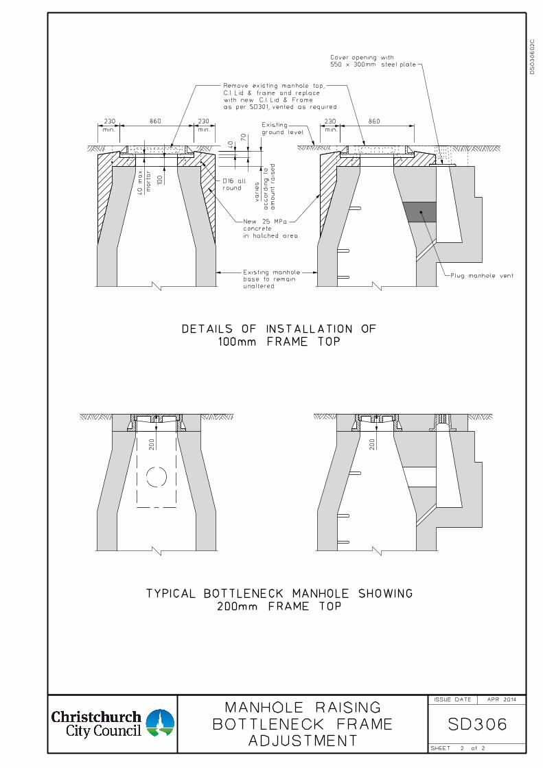
2
SD306ADJUSTMENT
BOTTLENECK FRAME
MANHOLE RAISING
am
ount rais
ed
accordin
g to
mortar
100mm FRAME TOP
DETAILS OF INSTALLATION OF
200mm FRAME TOP
TYPICAL BOTTLENECK MANHOLE SHOWING
min. min. min.
230
40
max.
230
100
70
varies
40
230
200
200
2
APR 2014
860
DS
030
60
2C
860
in hatched area
concrete
New 25 MPa
round
D16 all
unaltered.
base to remain
Existing manhole Plug manhole vent
as per SD301, vented as required
with new C.I. Lid & Frame
C.I. Lid & frame and replace
Remove existing manhole top,
ground level
Existing
550 x 300mm steel plate
Cover opening with
ISSUE DATE
SHEET of
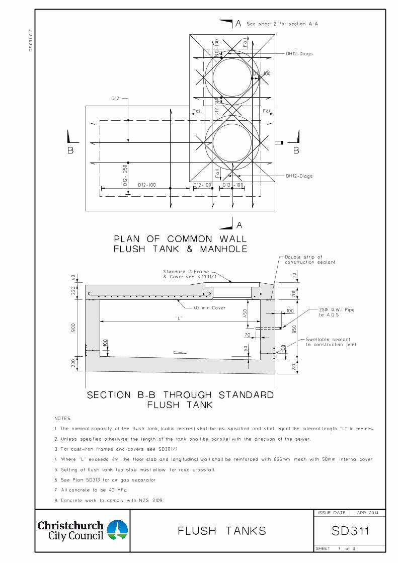
1
FLUSH TANKS SD311
D12- 250
D12-100 D12-100 D12 -100
A
B B
D12-100
D12-10
0D12-10
0
Fall
Fall
FallFall
See sheet 2 for section A-A
2
A
230
950
230
900
230
50
70
450
"L"
10040 min. Cover
40
200
70
100
100
D12
FLUSH TANK & MANHOLE
PLAN OF COMMON WALL
to A.G.S.
25< G.W.I. Pipe
FLUSH TANK
SECTION B-B THROUGH STANDARD
NOTES:
1. The nominal capacity of the flush tank, (cubic metres) shall be as specified and shall equal the internal length "L" in metres.
2. Unless specified otherwise the length of the tank shall be parallel with the direction of the sewer.
3. For cast-iron frames and covers see SD301/1.
4. Where "L" exceeds 4m the floor slab and longitudinal wall shall be reinforced with 665mm mesh with 50mm internal cover.
5. Setting of flush tank top slab must allow for road crossfall.
6. See Plan SD313 for air gap separator.
7. All concrete to be 40 MPa.
8. Concrete work to comply with NZS 3109.
DH12-Diags
DH12-Diags
construction sealant
Double strip of
to construction joint.
Swellable sealant
DS
03110
1F
APR 2014
& Cover see SD301/1
Standard CI Frame
ISSUE DATE
SHEET of
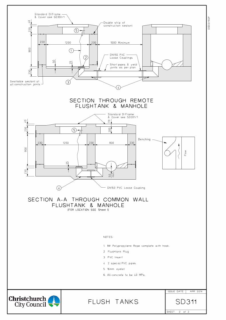
2
FLUSH TANKS SD311
FLUSHTANK & MANHOLE
SECTION A-A THROUGH COMMON WALL
joints as per plan
Short pipes & yield
FLUSHTANK & MANHOLE
SECTION THROUGH REMOTE
Flo
w
230
900
230 1200 230
50
25
1000 Mimimum
230
40
DN150 PVC Loose Coupling
1
2
3
4
Loose Couplings
DN150 PVC
(FOR LOCATION SEE Sheet 1)
230
40
70
Benching
230230 900
200
min.
50
900
230 1200
230
25
4
2
NOTES:
1. 8< Polypropylene Rope complete with hook.
2. Flushtank Plug.
3. PVC Insert.
4. 2 special PVC pipes.
5. 16mm eyelet.
6. All concrete to be 40 MPa.
5
5
construction sealant
Double strip of
all construction joints.
Swellable sealant at
DS
03110
2F
APR 2014
& Cover see SD301/1
Standard DI Frame
& Cover see SD301/1
Standard DI Frame
ISSUE DATE
SHEET of
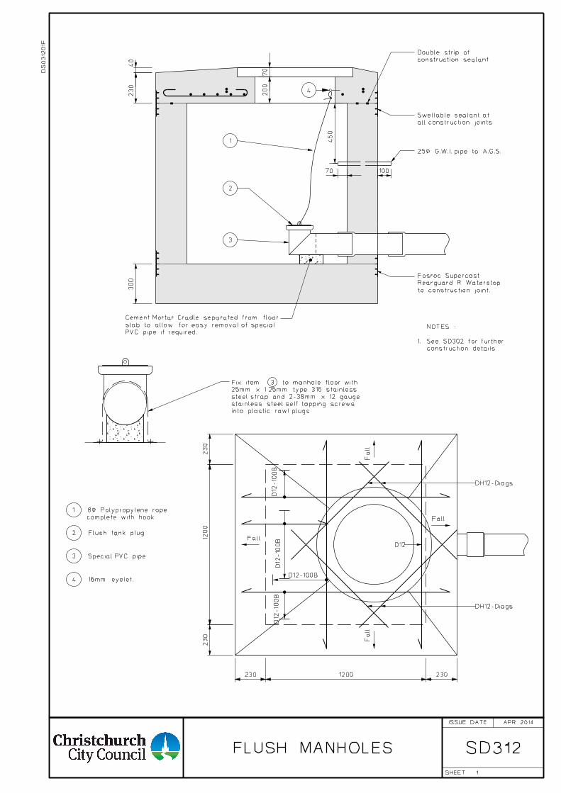
FLUSH MANHOLES SD312
PVC pipe if required.
slab to allow for easy removal of special
Cement Mortar Cradle separated from floor
into plastic rawl plugs.
stainless steel self tapping screws
steel strap and 2-38mm x 12 gauge
25mm x 1.25mm type 316 stainless
Fix item 3 to manhole floor with
230
230
D12-100B
D12-10
0B
D12-10
0B
D12-10
0B
300
Fall
Fall
Fall
Fall
1
2
3
25< G.W.I. pipe to A.G.S.
construction details.
1. See SD302 for further
NOTES :
230
40
200
70
450
70 100
1
to construction joint.
Rearguard R Waterstop
Fosroc Supercast
D12
4 16mm eyelet.
2 Flush tank plug.
3 Special PVC pipe.
complete with hook.
1 8< Polypropylene rope
DH12-Diags
DH12-Diags
construction sealant
Double strip of
all construction joints.
Swellable sealant at
APR 2014
DS
03120
1F
4
ISSUE DATE
SHEET
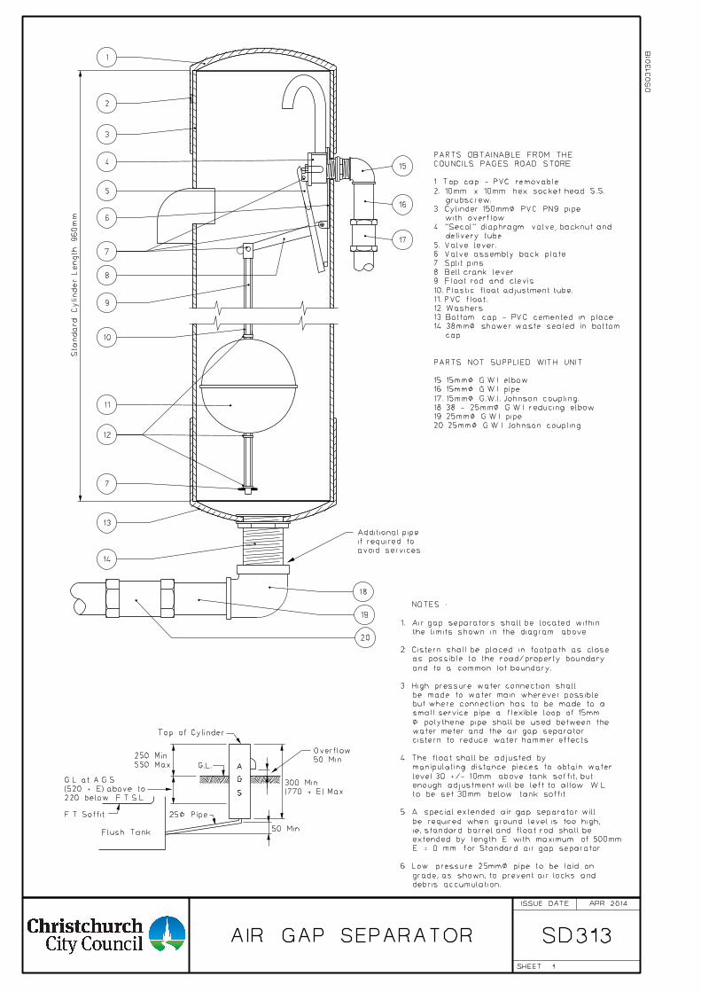
AIR GAP SEPARATOR
1
SD313
Top of Cylinder
A
G
S
Flush Tank
25< Pipe
(770 + E) Max
300 Min
50 Min
Overflow
550 Max
250 Min
50 Min
F.T. Soffit
220 below F.T.S.L.
(520 + E) above to
G.L. at A.G.S
G.L.
and to a common lot boundary.
as possible to the road/property boundary
2. Cistern shall be placed in footpath as close
the limits shown in the diagram above.
1. Air gap separators shall be located within
NOTES :
debris accumulation.
grade, as shown, to prevent air locks and
6. Low pressure 25mm< pipe to be laid on
E = 0 mm for Standard air gap separator.
extended by length E with maximum of 500mm.
ie, standard barrel and float rod shall be
be required when ground level is too high,
5. A special extended air gap separator will
to be set 30mm below tank soffit.
enough adjustment will be left to allow W.L.
level 30 +/- 10mm above tank soffit, but
manipulating distance pieces to obtain water
4. The float shall be adjusted by
cistern to reduce water hammer effects.
water meter and the air gap separator
< polythene pipe shall be used between the
small service pipe a flexible loop of 15mm
but where connection has to be made to a
be made to water main wherever possible
3. High pressure water connection shall
1
2
3
4
5
6
7
8
9
10
11
12
13
14
7
15
16
17
18
19
20
avoid services.
if required to
Additional pipe
Sta
ndard
Cylinder Length 960
mm
APR 2014
DS
03130
1B
20. 25mm< G.W.I. Johnson coupling.
19. 25mm< G.W.I. pipe.
18. 38 - 25mm< G.W.I. reducing elbow.
17. 15mm< G.W.I. Johnson coupling.
16. 15mm< G.W.I. pipe.
15. 15mm< G.W.I. elbow.
PARTS NOT SUPPLIED WITH UNIT:
cap.
14. 38mm< shower waste sealed in bottom
13. Bottom cap - PVC cemented in place.
12. Washers
11. PVC float.
10. Plastic float adjustment tube.
9. Float rod and clevis.
8. Bell crank lever.
7. Split pins.
6. Valve assembly back plate.
5. Valve lever.
delivery tube.
4. "Secol" diaphragm valve, backnut and
with overflow.
3. Cylinder 150mm< PVC PN9 pipe
grubscrew.
2. 10mm x 10mm hex socket head S.S.
1. Top cap - PVC removable.
COUNCILS PAGES ROAD STORE:
PARTS OBTAINABLE FROM THE
ISSUE DATE
SHEET
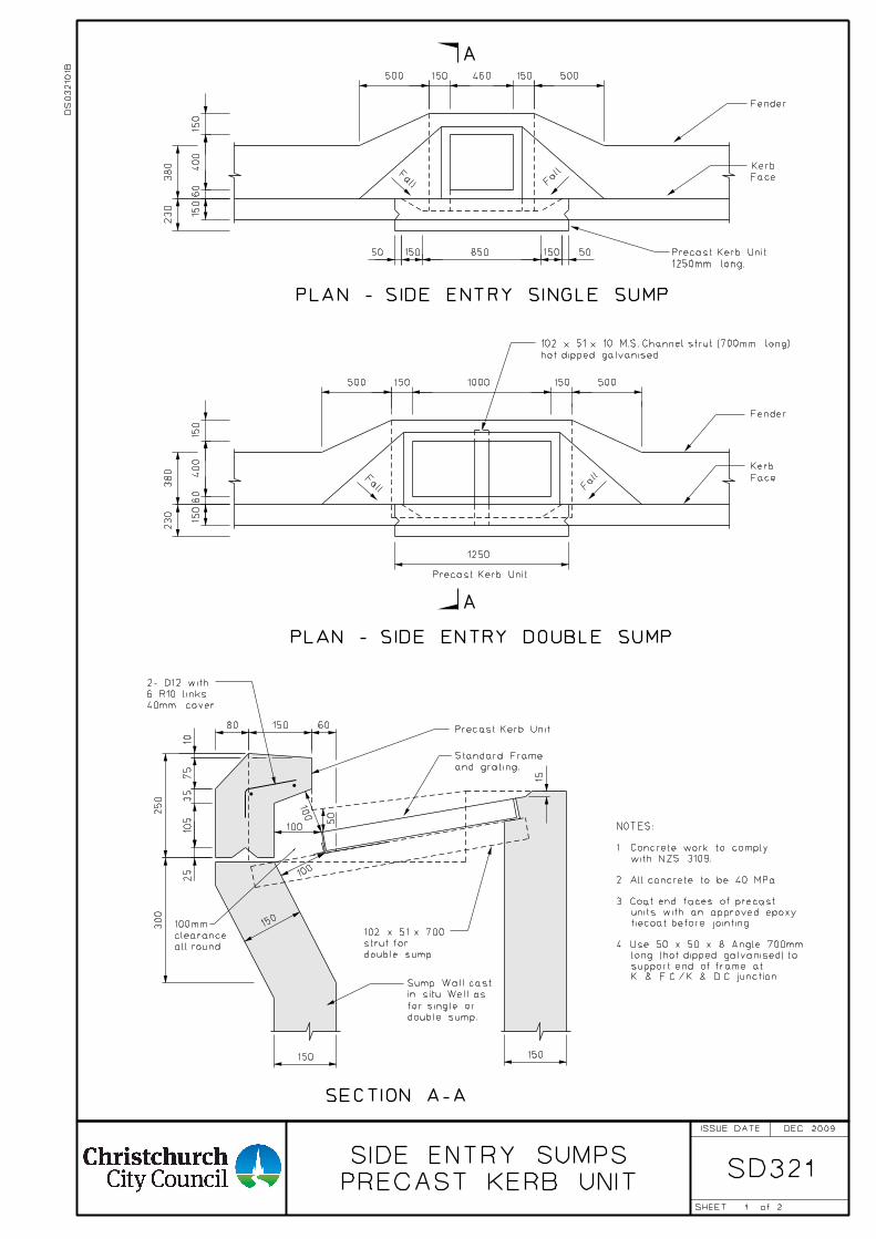
1
SD321
Precast Kerb Unit
and grating.
Standard Frame
double sump
strut for
102 x 51 x 700
40mm cover.
6 R10 links
2- D12 with
SECTION A-A
double sump.
for single or
in situ. Well as
Sump Wall cast
50
150150
300
250
25
105
35
75
10
150
80 150 60
15
100
100
100
all round
clearance
100mm
60
400
150 460 150
Fall F
all
850 150150 5050
PLAN - SIDE ENTRY SINGLE SUMP
1000150 150
PLAN - SIDE ENTRY DOUBLE SUMP
Fender
Fender
Face
Kerb
Face
KerbFall F
all
1250mm long.
Precast Kerb Unit
500
A
A
hot dipped galvanised
102 x 51 x 10 M.S. Channel strut (700mm long)
Precast Kerb Unit
500 500
230
380
150
500
1250
150
60
400
230
380
150
150
2
PRECAST KERB UNIT
SIDE ENTRY SUMPS
DS
03210
1B
DEC 2009
NOTES:
1. Concrete work to comply
2. All concrete to be 40 MPa.
3. Coat end faces of precast
units with an approved epoxy
tiecoat before jointing.
4. Use 50 x 50 x 8 Angle 700mm
long (hot dipped galvanised) to
support end of frame at
K & F.C./K & D.C. junction.
with NZS 3109.
ISSUE DATE
SHEET of
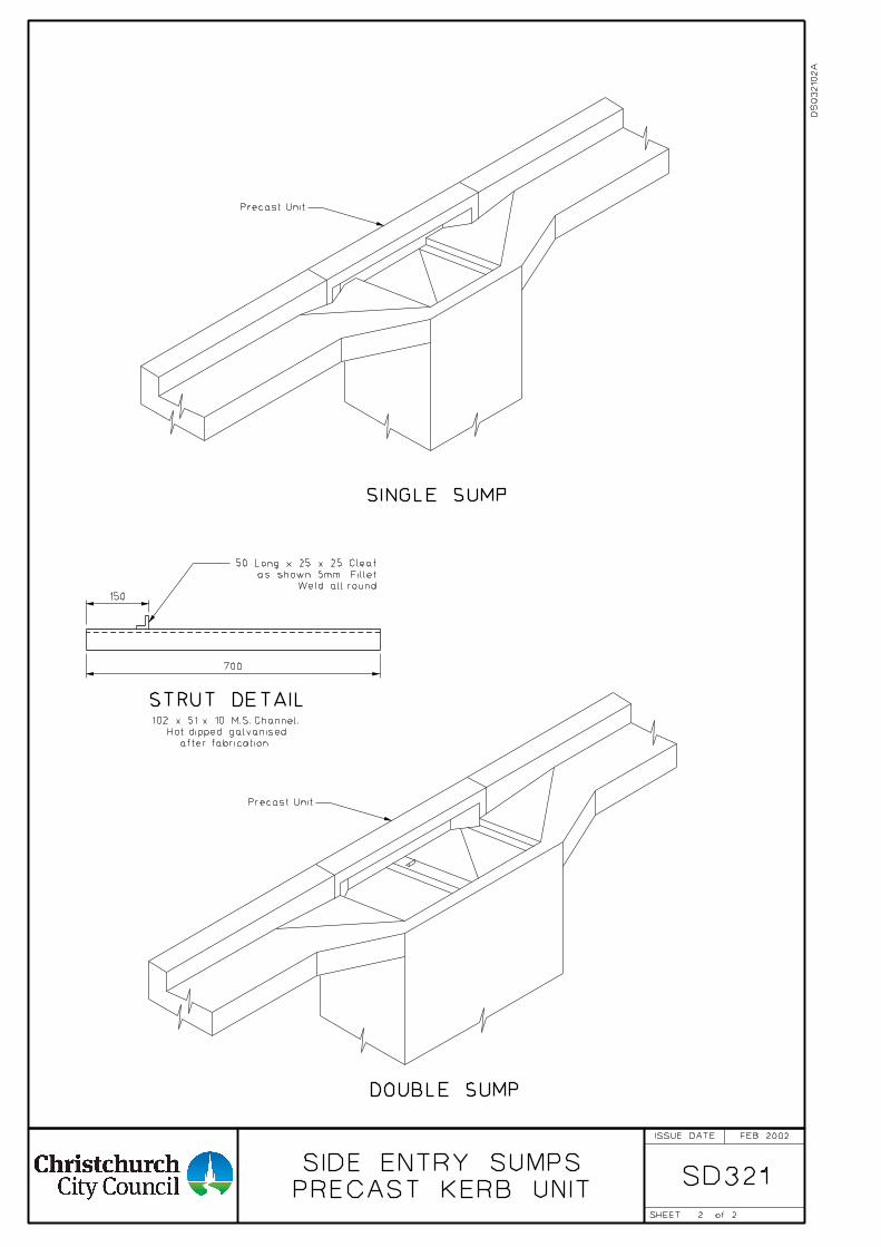
2
DS
03210
2A
SD321
Precast Unit
SINGLE SUMP
Precast Unit
DOUBLE SUMP
FEB 2002
2
PRECAST KERB UNIT
SIDE ENTRY SUMPS
ISSUE DATE
SHEET of
Weld all round
as shown 5mm Fillet
50 Long x 25 x 25 Cleat
STRUT DETAIL
after fabrication.
Hot dipped galvanised
102 x 51 x 10 M.S. Channel.
700
150
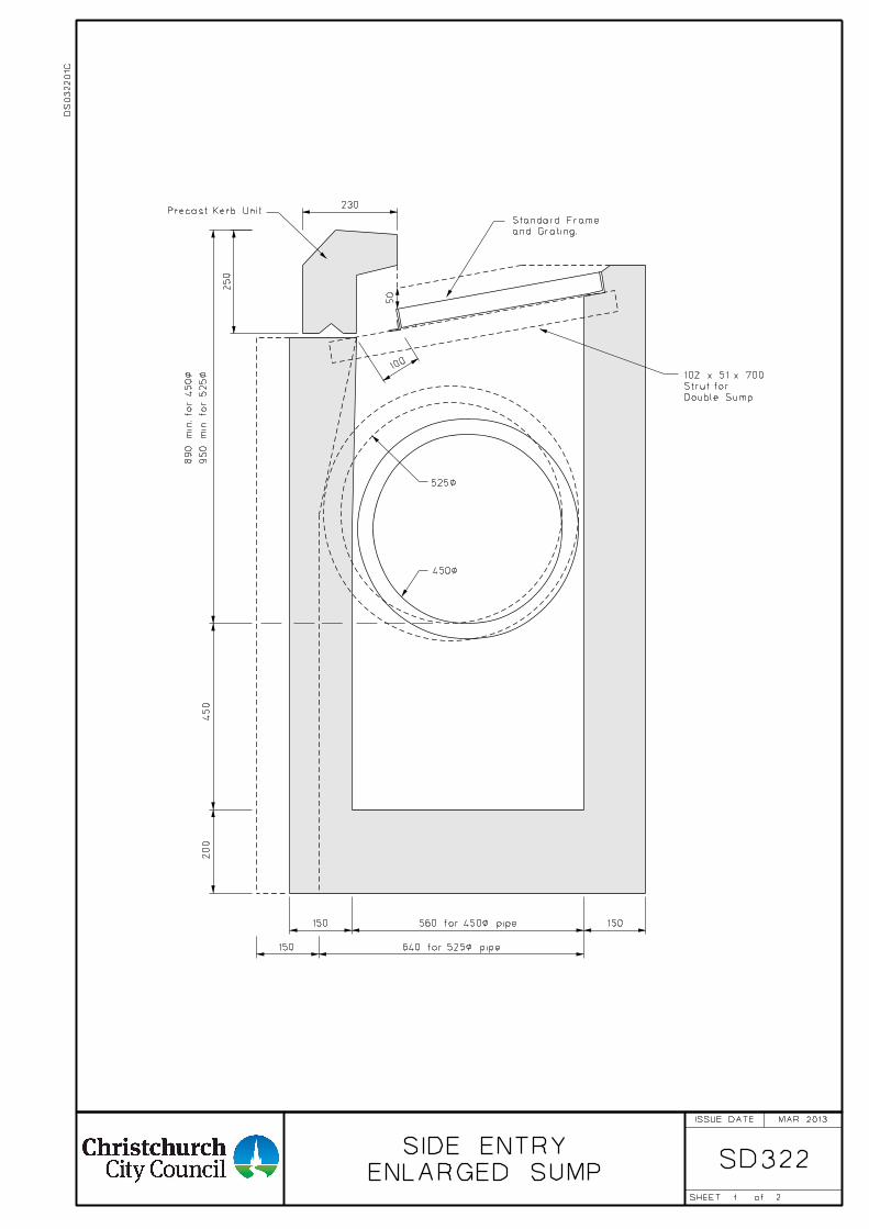
1
SD322ENLARGED SUMP
SIDE ENTRY
2
230
150 150
250
200
450
50
100
450<
525<
150
and Grating.
Standard Frame
Double Sump
Strut for
102 x 51 x 700
Precast Kerb Unit
560 for 450< pipe
640 for 525< pipe
950
min. for 525<
890
min. for 450<
MAR 2013
DS
03220
1C
ISSUE DATE
SHEET of
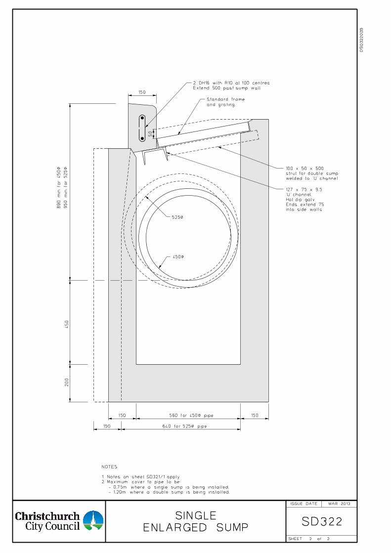
SD322
2
ENLARGED SUMP
SINGLE
2
NOTES:
- 1.20m where a double sump is being installed.
- 0.75m where a single sump is being installed.
2. Maximum cover to pipe to be:
1. Notes on sheet SD321/1 apply.
150
150 150
200
450
50
150
560 for 450< pipe
640 for 525< pipe
and grating.
Standard frame
into side walls.
Ends extend 75
Hot dip galv.
'U' channel.
127 x 75 x 9.5
welded to 'U' channel.
strut for double sump
100 x 50 x 500
950
min. for 525<
890
min. for 450<
525<
450<
MAR 2013
DS
03220
2B
Extend 500 past sump wall.
2 DH16 with R10 at 100 centres.
ISSUE DATE
SHEET of
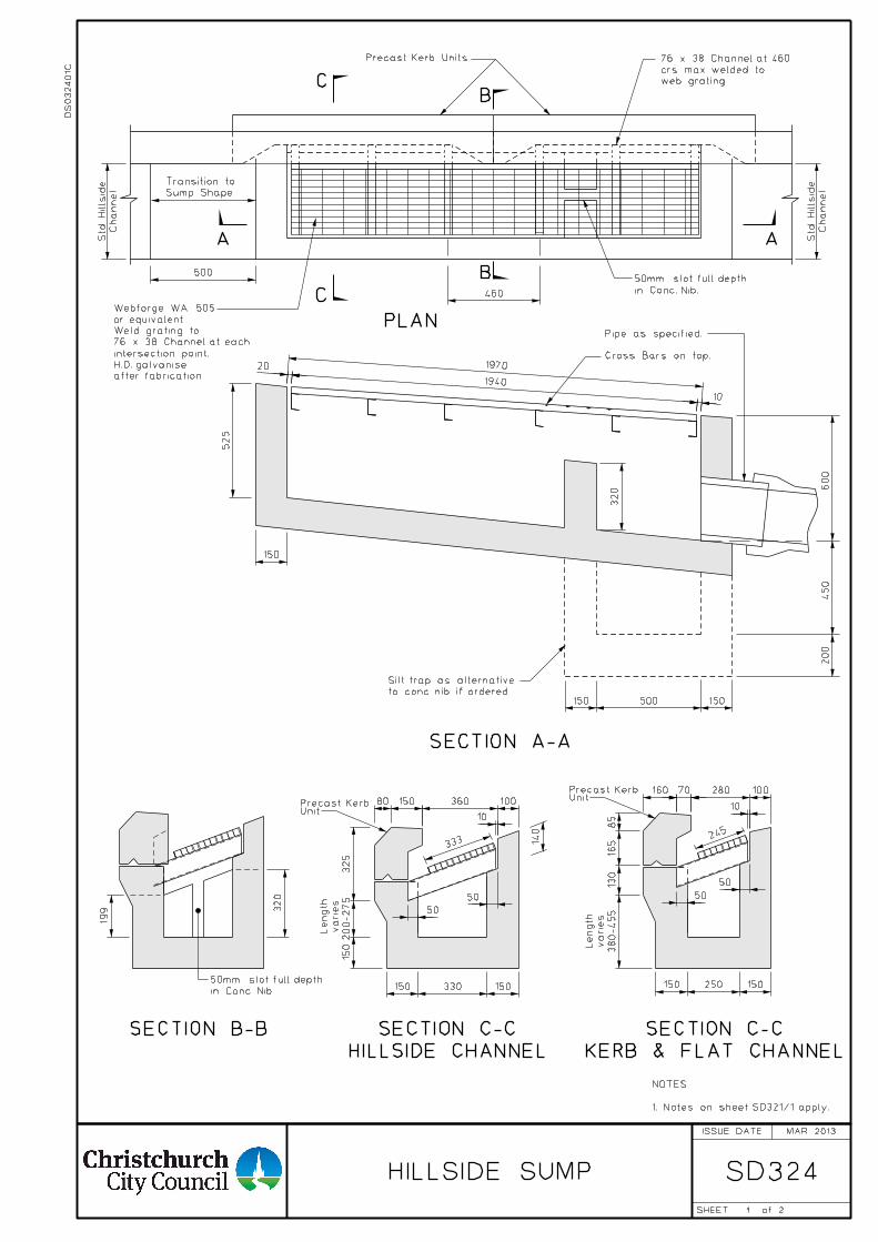
1
SD324HILLSIDE SUMP
Precast Kerb Units
in Conc. Nib.
50mm slot full depth
Sump Shape
Transition to
A A
B
B
C
C
PLAN
SECTION A-A
SECTION B-B
Cross Bars on top.
Pipe as specified.
to conc. nib if ordered.
Silt trap as alternative
460
500
20
150 500 150
200
450
600
360 100
10
15080
150 330 150
50
50
333
150 250 150
160 70 280 100
50
50
245
10
1970
1940
10
525
85
165
130
380-455
140
320
150
325
200-275
150
web grating.
crs max. welded to
76 x 38 Channel at 460
Channel
Std.
Hillsid
e
Channel
Std.
Hillsid
e
2
NOTES:
1. Notes on sheet SD321/1 apply.
after fabrication.
H.D. galvanise
intersection point.
76 x 38 Channel at each
Weld grating to
or equivalent.
Webforge WA 505
MAR 2013
320
199
in Conc. Nib.
50mm slot full depth
varies
Length
KERB & FLAT CHANNEL
SECTION C-C
HILLSIDE CHANNEL
SECTION C-C
varies
Length
DS
03240
1C
UnitPrecast Kerb
UnitPrecast Kerb
ISSUE DATE
SHEET of
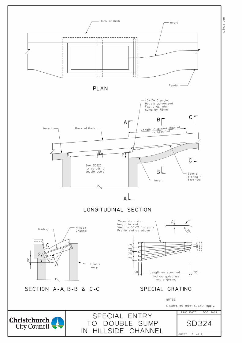
2
SD324IN HILLSIDE CHANNEL
TO DOUBLE SUMP
SPECIAL ENTRY
Back of KerbInvert
Fender
PLAN
7530
3030
30
75
75
75
C
C
B
A
BA
50 30
A
B
C
Invert
Back of KerbInvert
Channel
HillsideGrating
sump
Double
entire grating
Hot dip galvanise
SECTION A-A, B-B & C-C SPECIAL GRATING
Profile end as above.
Weld to 50x12 flat plate.
length to suit.
25mm dia rods
sump by 75mm.
Cast ends into
Hot dip galvanised.
40x40x10 angle.
LONGITUDINAL SECTION
double sump
for details of
See SD325
as specifiedLength of
formed channel
specified
grating if
Special25
30°
50
100
Length as specified
100
2
DEC 2009
DS
03240
2B
NOTES:
1. Notes on sheet SD321/1 apply.
ISSUE DATE
SHEET of
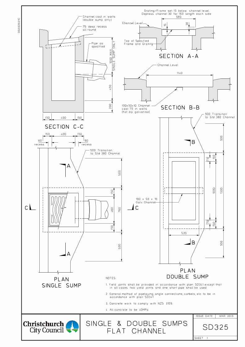
1
FLAT CHANNEL
SINGLE & DOUBLE SUMPSSD325
specified
Pipe as
Channel Level
to Std. 380 Channel
500 Transition
SECTION A-A
SECTION B-B
SINGLE SUMP
PLAN
B
B
A
A
(double sump only)
Channel cast in walls
500
150
460
150
500
150 400 150
200
450
150 400 150
150
1000
150
1300
1140
15 30
760
SIN
GL
E
SU
MP
ON
LY
1000
MA
X.
500
500
CC
SECTION C-C
all round
75 deep recess
recessrecess
580
60 60
70
70
520
NOTES:
1. Yield joints shall be provided in accordance with plan SD341 except that
in all cases two yield joints and one short pipe shall be used.
2. General method of pipelaying, angle connections, corbels, etc. to be in
accordance with plan SD341.
3. Concrete work to comply with NZS 3109.
4. All concrete to be 40MPa.
Channel Level
Depress channel 30 for 150 length each side.
Grating/Frame set 15 below channel level.
Frame and Grating
Top of Specified
(hot dip galvanise)
cast 75 in walls
100x50x10 Channel
DOUBLE SUMP
PLAN
to Std. 380 Channel
500 Transition
MAR 2013
Galv. Channel
100 x 50 x 10
DS
03250
1C
ISSUE DATE
SHEET
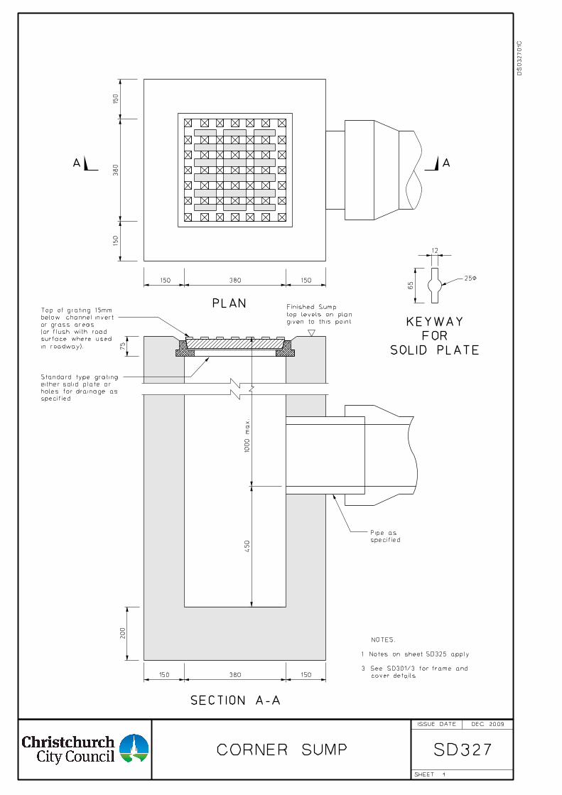
1
CORNER SUMP SD327
150
380
150
380 150150
AA
specified.
holes for drainage as
either solid plate or
Standard type grating
PLAN
specified.
Pipe as
200
150 380 150
75
450
1000
max.
SECTION A-A
65
12
25<
SOLID PLATE
FOR
KEYWAY
in roadway).
surface where used
(or flush with road
or grass areas
below channel invert
Top of grating 15mm
given to this point
top levels on plan
Finished Sump
DEC 2009
DS
03270
1C
cover details.
3. See SD301/3 for frame and
1. Notes on sheet SD325 apply.
NOTES:
ISSUE DATE
SHEET
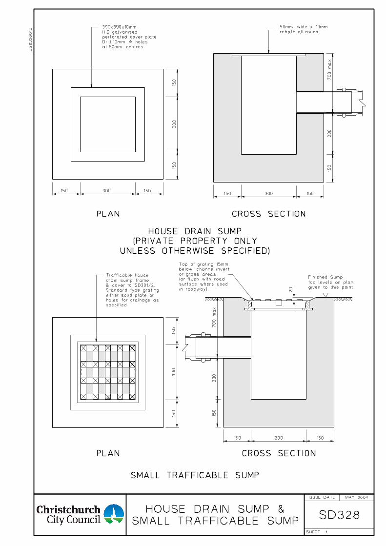
1
SD328
PLAN
CROSS SECTIONPLAN
rebate all round.
50mm wide x 13mm
CROSS SECTION
at 50mm centres.
Drill 12mm < holes
perforated cover plate.
H.D. galvanised
390x390x10mm
& cover to SD301/2.
drain sump frame
Trafficable house
specified.
holes for drainage as
either solid plate or
Standard type grating
150
300
150
150300150150300150
700
max.
150
230
20
150
300
150
150 300 150
700
max.
150
230
SMALL TRAFFICABLE SUMP
SMALL TRAFFICABLE SUMP
HOUSE DRAIN SUMP &
MAY 2004
UNLESS OTHERWISE SPECIFIED)
(PRIVATE PROPERTY ONLY
HOUSE DRAIN SUMP
given to this point
top levels on plan
Finished Sump
in roadway).
surface where used
(or flush with road
or grass areas
below channel invert
Top of grating 15mm
DS
03280
1B
ISSUE DATE
SHEET
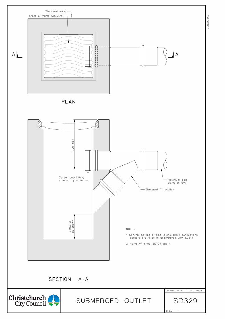
SECTION A-A
1
A
PLAN
A
700
max.
as sho
wn
230-450
SD329
DEC 2009
Standard sump
Grate & frame SD301/5
glue into junction
Screw cap fitting
Standard ’Y’ junction
diameter 150<
Maximum pipe
SUBMERGED OUTLET
DS
03290
1A
NOTES:
1. General method of pipe laying, angle connections,
corbels etc. to be in accordance with SD341.
2. Notes on sheet SD325 apply.
ISSUE DATE
SHEET
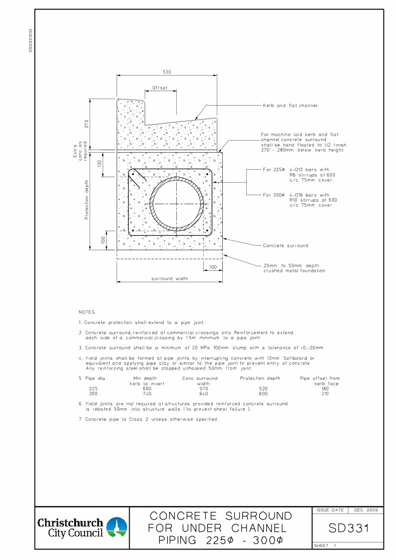
1 PIPING 225< - 300<
FOR UNDER CHANNEL
CONCRETE SURROUND
SD331
Kerb and flat channel.
For 300<
c/c 75mm cover.
R6 stirrups at 600
4-D12 bars with
c/c 75mm cover.
R10 stirrups at 600
4-D16 bars with
Concrete surround
Offset
530
surround width
Prote
ction depth
270
100
100
130
required
conc. as
Extr
a
crushed metal foundation.
25mm to 50mm depth
For 225<
270 - 280mm below kerb height.
shall be hand floated to U2 finish.
channel concrete surround
For machine laid kerb and flat
DEC 2009
7. Concrete pipe to Class 2 unless otherwise specified.
is rebated 50mm into structure walls ( to prevent shear failure ).
6. Yield joints are not required at structures provided reinforced concrete surround
300 740 640 600 210
225 660 570 520 180
kerb to invert width kerb face
5. Pipe dia. Min depth Conc. surround Protection depth Pipe offset from
Any reinforcing steel shall be stopped unhooked 50mm from joint.
equivalent and applying pipe clay or similar to the pipe joint to prevent entry of concrete.
4. Yield joints shall be formed at pipe joints by interrupting concrete with 12mm Softboard or
3. Concrete surround shall be a minimum of 20 MPa 100mm slump with a tolerance of +0,-20mm.
each side of a commercial crossing by 1.5m minimum to a pipe joint.
2. Concrete surround, reinforced at commercial crossings only. Reinforcement to extend
1. Concrete protection shall extend to a pipe joint.
NOTES:
DS
03310
1D
ISSUE DATE
SHEET
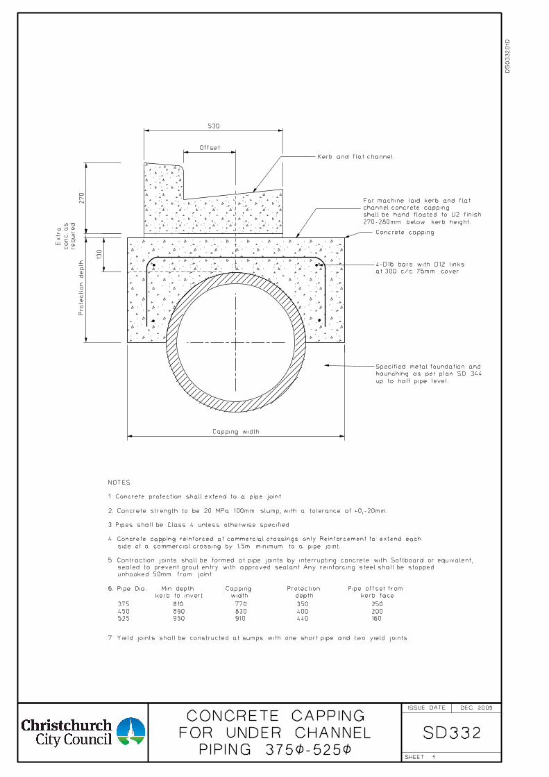
1 PIPING 375<-525<
FOR UNDER CHANNEL
CONCRETE CAPPING
SD332
at 300 c/c 75mm cover.
4-D16 bars with D12 links
Concrete capping
Capping width
Prote
ction depth
required
conc. as
Extr
a
130
Kerb and flat channel.
Offset
530
270
up to half pipe level.
haunching as per plan SD 344
Specified metal foundation and
525
450
375
950
890
810
910
830
770
440
400
350
160
200
250
270-280mm below kerb height.
shall be hand floated to U2 finish
channel concrete capping
For machine laid kerb and flat
DEC 2009
7. Yield joints shall be constructed at sumps with one short pipe and two yield joints.
kerb to invert width depth kerb face
6. Pipe Dia. Min depth Capping Protection Pipe offset from
unhooked 50mm from joint.
sealed to prevent grout entry with approved sealant. Any reinforcing steel shall be stopped
5. Contraction joints shall be formed at pipe joints by interrupting concrete with Softboard or equivalent,
side of a commercial crossing by 1.5m minimum to a pipe joint.
4. Concrete capping reinforced at commercial crossings only. Reinforcement to extend each
3. Pipes shall be Class 4 unless otherwise specified.
2. Concrete strength to be 20 MPa 100mm slump, with a tolerance of +0,-20mm.
1. Concrete protection shall extend to a pipe joint.
NOTES:
DS
03320
1D
ISSUE DATE
SHEET
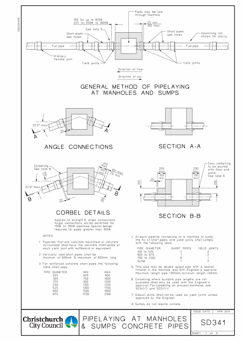
1
SD341
through manhole.
Pipes may be laid
225 for 900< to 1800<
100 for up to 825<
see notes
Short pipes
See note 5
100 max
25 min
see notes
Short pipes
shown for clarity
Haunching not
flexible joint
Ordinary
Yield joints Yield joints
Direction of flow
Direction of lay
ANGLE CONNECTIONS
CORBEL DETAILS
required for pipes greater than 300<.
100< to 300< pipelines. Special design
Angle connections will be permitted for
Applies to straight & angle connections.
Full pipeFull pipe
A
A
250
B
SECTION A-A
SECTION B-B
B
25
max
150
25 150
25
150
22.5° max.
22.5° max.
150
AT MANHOLES AND SUMPS
GENERAL METHOD OF PIPELAYING
675
600
525
450
375
300
225
PIPE DIAMETER
1700
1500
1300
1100
900
750
600
MIN
2100
1900
1700
1450
1200
1000
800
MAX
min
150
min
150
min
150
max
250
max
250100 max.25 min.
See note 6.
Corbelling
DS
03410
1E
APR 2014
5
& SUMPS CONCRETE PIPES
PIPELAYING AT MANHOLES
table shall appy.
3. For reinforced concrete short pipes the following
minimum of 500mm & maximum of 800mm long.
2. Vertically cast short pipes shall be
each yield joint with softboard or equivalent.
surrounded shall have the concrete interrupted at
1. Pipelines that are concrete haunched or concrete
NOTES:
with the following table:
the No. of short pipes and yield joints shall comply
4. At each pipeline connecting to a manhole or sump,
Sump
750 to 2100
600 to 675
100 to 525
PIPE DIAMETER
1
0
1
2
SHORT PIPES
2
1
2
3
YIELD JOINTS
5. This pipe may be double spigot pipe with a socket
finisher in the manhole wall with Engineer's approval.
Maximum length pipe 1300mm, minimum length 450mm.
6. Corbelling where suitable pipe lengths are not
available shall only be used with the Engineer's
approval. For corbelling on precast manholes see
SD341/2 and SD341/4.
7. Gibault joints shall not be used as yield joints unless
approved by the Engineer.
8. Sumps do not require corbels.
See note 6
walls.
with floor and
to be poured
Conc. corbelling
ISSUE DATE
SHEET of
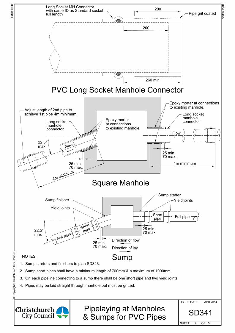
© C
opyright
Chr istc
hurc
h City C
ouncil
ISSUE DATE
SHEET OF
Pipe grit coated
200
260 min
PVC Long Socket Manhole Connector
full lengthwith same ID as Standard socketLong Socket MH Connector
200
70 max.25 min.
70 max.25 min.
Yield joints
Full pipe
pipeSh
ort
70 max.25 min.
Full pipe
Yield joints
pipeShort
70 max.25 min.
Direction of lay
Direction of flow
Sump
Sump starter
Sump finisher
Flow
Flow
Square Manhole
max
22.5°
connectormanholeLong socket connector
manholeLong socket
max
22.5°
4. Pipes may be laid straight through manhole but must be gritted. 3. On each pipeline connecting to a sump there shall be one short pipe and two yield joints. 2. Sump short pipes shall have a minimum length of 700mm & a maximum of 1000mm.
1. Sump starters and finishers to plan SD343. NOTES:
4m minim
um
4m minimum
achieve 1st pipe 4m minimum.
Adjust length of 2nd pipe toto existing manhole.
Epoxy mortar at connections
to existing manhole.
at connections
Epoxy mortar
2 5
DS134102
B
DS134102
B
Pipelaying at Manholes
& Sumps for PVC PipesSD341
APR 2014
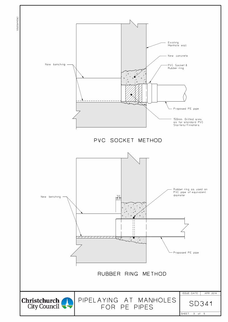
3
SD341FOR PE PIPES
PIPELAYING AT MANHOLES
Starters/Finishers
as for standard PVC
150mm Gritted area
Proposed PE pipe
Manhole wall
Existing
New concrete
Rubber ring
PVC Socket &New benching
min.
New benchingdiameter
PVC pipe of equivalent
Rubber ring as used on
Proposed PE pipe
PVC SOCKET METHOD
RUBBER RING METHOD
50
APR 2014
5
DS
03410
3C
ISSUE DATE
SHEET of
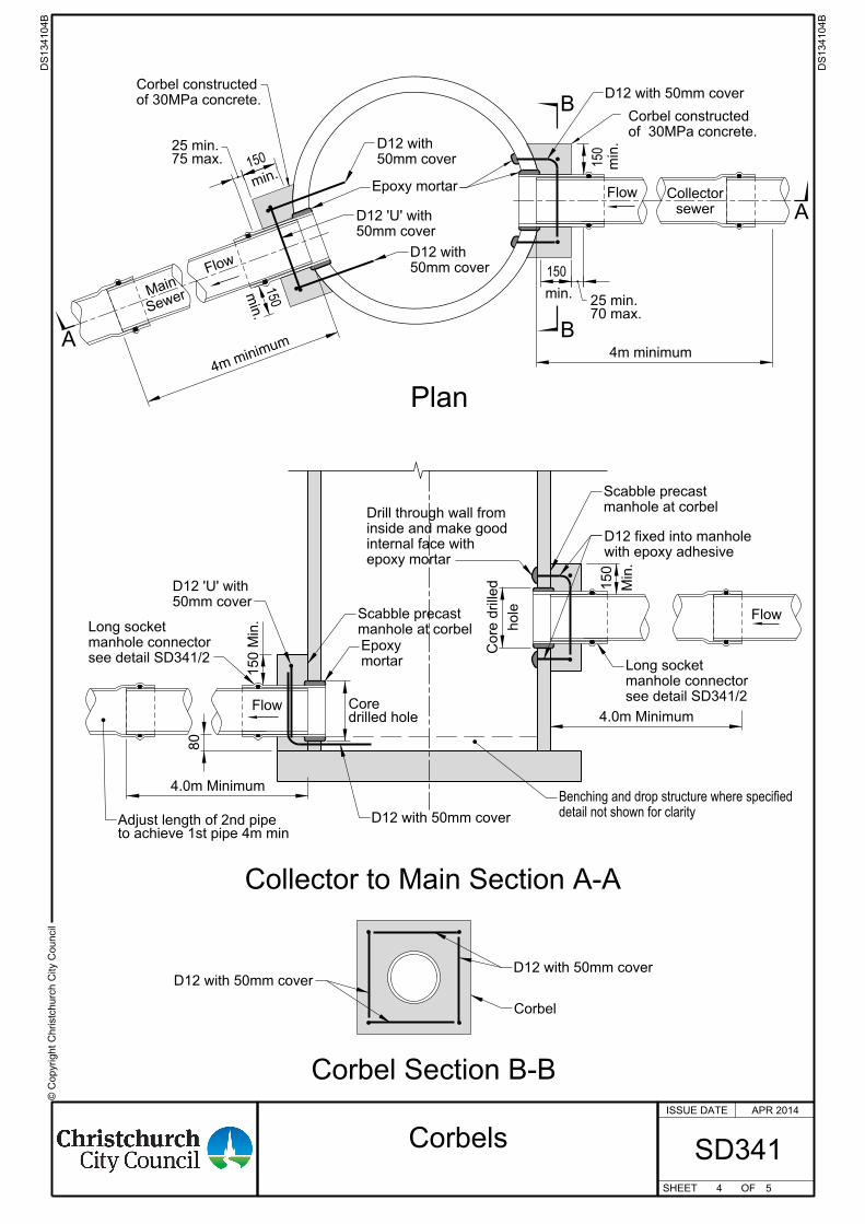
© C
opyright
Chr istc
hurc
h City C
ouncil
ISSUE DATE
SHEET OF
Flow
Flow
to achieve 1st pipe 4m minAdjust length of 2nd pipe
4.0m Minimumdrilled holeCore
150
150
75 max.25 min.
150
Flow
Flow
70 max.25 min.
min.
min.
min.
150
min.
of 30MPa concrete.
Corbel constructed
of 30MPa concrete.
Corbel constructed
Plan
Collector to Main Section A-A
sewer
Collector
4m minimum
4m minim
um
SewerMain
50mm cover
D12 'U' with
50mm cover
D12 with
50mm cover
D12 with
Epoxy mortar
D12 with 50mm cover
B
BA
A
Corbel Section B-B
mortar
Epoxy
80
manhole at corbel
Scabble precast
150 Min.
50mm cover
D12 'U' with
D12 with 50mm cover
D12 with 50mm coverD12 with 50mm cover
Corbel
manhole at corbel
Scabble precast
Min.
150
with epoxy adhesive
D12 fixed into manhole
see detail SD341/2
manhole connector
Long socket
see detail SD341/2
manhole connector
Long socket
hole
Core drilled
4.0m Minimum
epoxy mortar
internal face with
inside and make good
Drill through wall from
detail not shown for clarity
Benching and drop structure where specified
4 5
DS134104
B
DS134104
B
SD341
APR 2014
Corbels
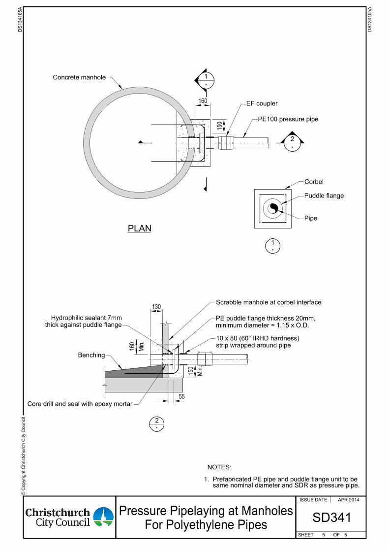
© C
opyright
Chr istc
hurc
h City C
ouncil
ISSUE DATE
SHEET OF
same nominal diameter and SDR as pressure pipe.1. Prefabricated PE pipe and puddle flange unit to be NOTES:
PLAN
1
2
Concrete manhole
EF coupler
PE100 pressure pipe
Corbel
Puddle flange
Pipe
1
2
Scrabble manhole at corbel interface
minimum diameter = 1.15 x O.D.
PE puddle flange thickness 20mm,
thick against puddle flange
Hydrophilic sealant 7mm
Benching
Core drill and seal with epoxy mortar
130
Min.
160
Min.
150
55
160
150
strip wrapped around pipe
10 x 80 (60° IRHD hardness)
5 5
DS134105
A
DS134105
A
SD341
APR 2014
Pressure Pipelaying at Manholes
For Polyethylene Pipes
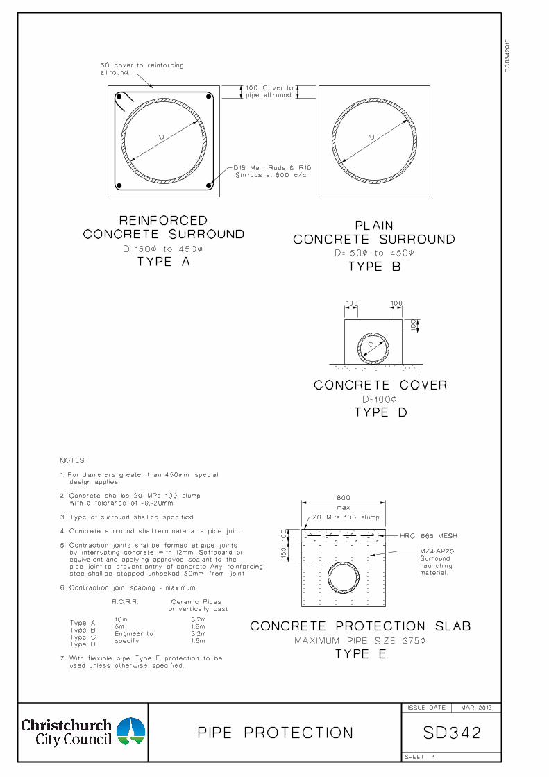
1
PIPE PROTECTION SD342
all round.
50 cover to reinforcing
pipe all round.
100 Cover to
D=150< to 450<D=150< to 450<
D=100<
TYPE A
CONCRETE SURROUND
REINFORCED
TYPE B
CONCRETE SURROUND
PLAIN
TYPE D
CONCRETE COVER
1.6m
3.2m
1.6m
3.2m
specify
Engineer to
5m
10m
Stirrups at 600 c/c.
D16 Main Rods & R10
100 100
100
D
DD
100
800
max
CONCRETE PROTECTION SLAB
MAXIMUM PIPE SIZE 375<
TYPE E
HRC 665 MESH
150
used unless otherwise specified.
7. With flexible pipe Type E protection to be
Type D
Type C
Type B
Type A
or vertically cast
R.C.R.R. Ceramic Pipes
6. Contraction joint spacing - maximum:
steel shall be stopped unhooked 50mm from joint.
pipe joint to prevent entry of concrete. Any reinforcing
equivalent and applying approved sealant to the
by interrupting concrete with 12mm Softboard or
5. Contraction joints shall be formed at pipe joints
4. Concrete surround shall terminate at a pipe joint.
3. Type of surround shall be specified.
with a tolerance of +0,-20mm.
2. Concrete shall be 20 MPa 100 slump
design applies.
1. For diameters greater than 450mm special
NOTES:
20 MPa 100 slump
material.
haunching
Surround
M/4:AP20
MAR 2013
DS
03420
1F
ISSUE DATE
SHEET
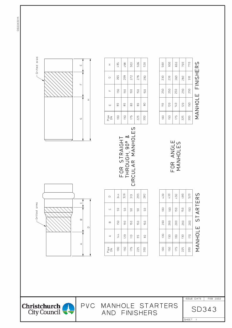
1
AND FINISHERS
PVC MANHOLE STARTERSSD343
Gritte
d area
AB
CD
100
150
175
225
300
144
150
50
344
129
113
95
82
150
150
150
150
50
50
50
50
329
313
295
282
CIR
CU
LA
R
MA
NH
OL
ES
TH
RO
UG
H, 90° &
FO
R S
TR
AIG
HT
100
150
175
225
300
150
150
150
150
150
100
150
175
225
300
100
150
175
225
300
130
200
430
130
100
200
200
200
200
430
450
480
520
MA
NH
OL
ES
FO
R
AN
GL
E
EF
GH
80
80
80
80
80
265
268
272
276
290
495
498
502
506
520
110
120
140
120
150
250
250
250
250
250
230
230
260
280
310
590
600
650
700
770
MA
NH
OL
E
ST
AR
TE
RS
MA
NH
OL
E
FINIS
HE
RS
Gritte
d area
130
170
150
150
150
100
100
AB
C
D
GF
E
H
DN
Pip
e
DN
Pip
e
FEB 2002
DS
03430
1A
ISSUE DATE
SHEET
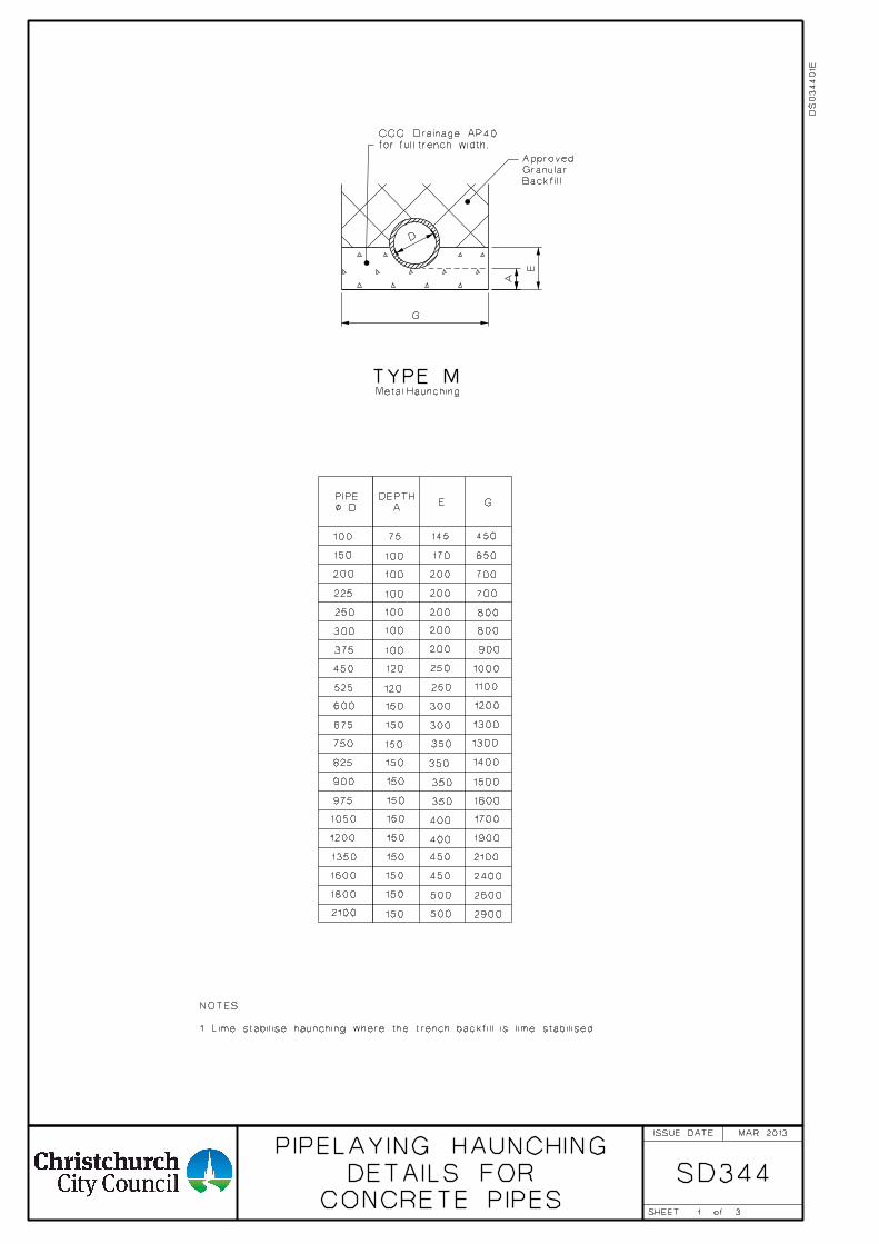
1 CONCRETE PIPES
DETAILS FOR
PIPELAYING HAUNCHING
SD344
Metal Haunching
TYPE M
100
150
150
150
150
150
150
150
150
150
150
150
150
150
200
225
250
300
375
450
525
600
675
750
825
900
975
1050
1200
1350
1600
1800
2100
75
100
100
100
100
100
100
120
120
E G
145
170
200
200
200
200
200
250
250
300
300
350
350
350
350
400
400
450
450
450
500
500
650
900
700
700
800
800
1000
1100
1200
1300
1300
1400
1500
1600
1700
1900
2100
2400
2600
2900
D
G
E
A
3
< D
PIPE
A
DEPTH
Backfill
Granular
Approved
for full trench width.
CCC Drainage AP40
MAR 2013
1. Lime stabilise haunching where the trench backfill is lime stabilised.
NOTES:
DS
03440
1E
ISSUE DATE
SHEET of
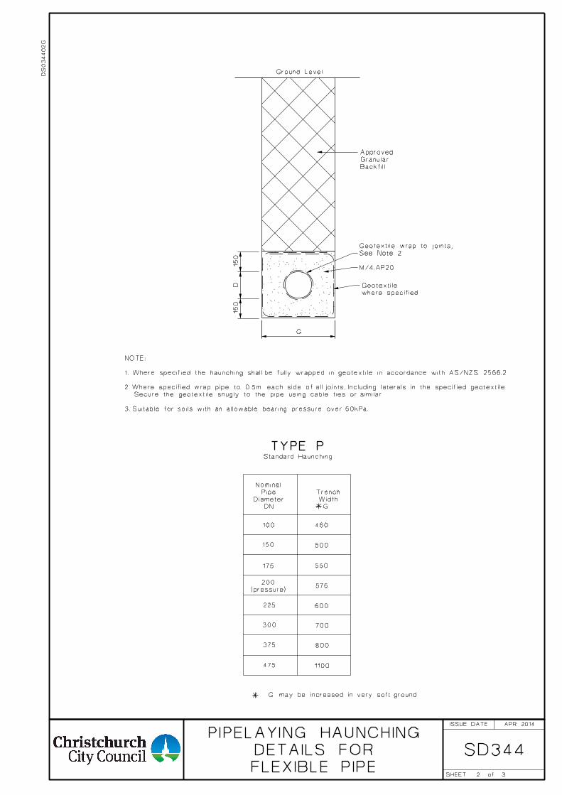
2
100
150
175
225
300
500
550
600
TYPE P
375
Standard Haunching
3
NOTE:
Secure the geotextile snugly to the pipe using cable ties or similar.
3. Suitable for soils with an allowable bearing pressure over 50kPa.
G may be increased in very soft ground.
SD344
DS
034402
G
1. Where specified the haunching shall be fully wrapped in geotextile in accordance with AS/NZS 2566.2
2. Where specified wrap pipe to 0.5m each side of all joints, Including laterals in the specified geotextile.
460
575(pressure)
200
700
800
1100475
DN
Diameter
Pipe
Nominal
G
Width
Trench
APR 2014
FLEXIBLE PIPE
DETAILS FOR
PIPELAYING HAUNCHING
Ground Level
150
D150
G
Backfill
Granular
Approved
See Note 2
Geotextile wrap to joints,
M/4:AP20
where specified
Geotextile
ISSUE DATE
SHEET of
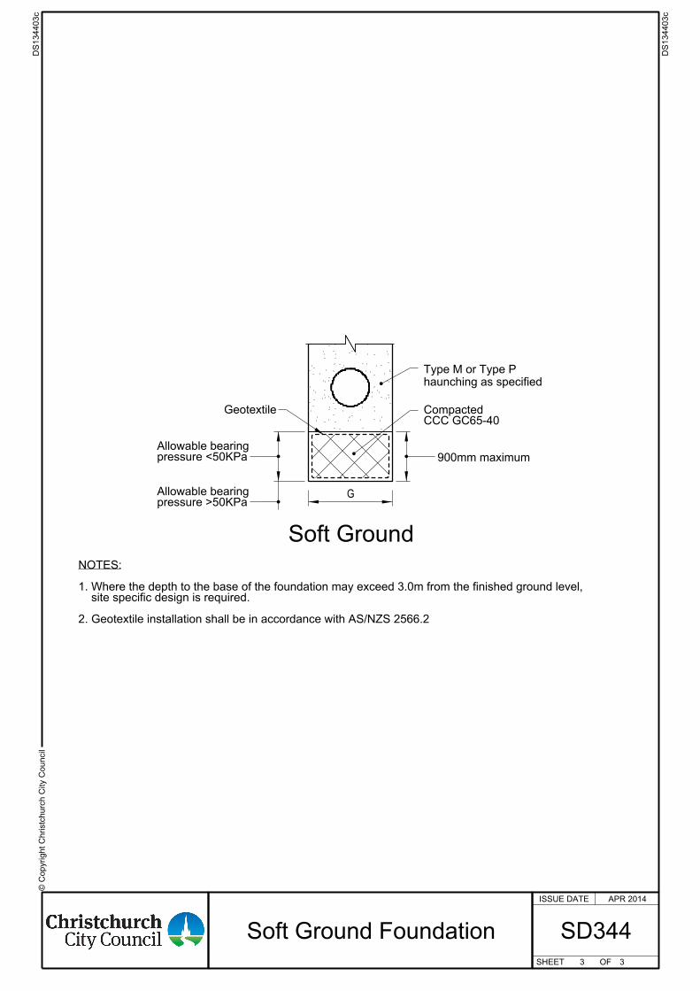
© C
opyright
Chr istc
hurc
h City C
ouncil
ISSUE DATE
SHEET OF
holedrilledCore
Soft Ground
G
CCC GC65-40Compacted
haunching as specified
Type M or Type P
900mm maximum pressure <50KPaAllowable bearing
pressure >50KPaAllowable bearing
Geotextile
2. Geotextile installation shall be in accordance with AS/NZS 2566.2
site specific design is required.1. Where the depth to the base of the foundation may exceed 3.0m from the finished ground level,
NOTES:
3 3
DS134403c
DS134403c
SD344Soft Ground Foundation
APR 2014
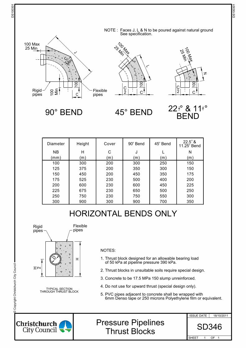
' C
opyr ight
Christc
hur c
h City C
ouncil
ISSUE DATE
SHEET OF
H
o o
o
o
pipesRigid
pipesFlexible
25 Min
100 M
ax
100 Max
25 Min
Min
100
100 Max25 Min
J
C
Min
C
100
See specification.NOTE : Faces J, L & N to be poured against natural ground
L
N
100
2 C
100
90° BEND 45° BENDBEND
22 ° & 11 °
pipesRigid
2
pipesFlexible
HORIZONTAL BENDS ONLY
2
1
4
1
C C
H
D
2 C
6mm Denso tape or 250 microns Polyethylene film or equivalent. 5. PVC pipes adjacent to concrete shall be wrapped with 4. Do not use for upward thrust (special design only). 3. Concrete to be 17.5 MPa 150 slump unreinforced. 2. Thrust blocks in unsuitable soils require special design. of 50 kPa at pipeline pressure 390 kPa.1. Thrust block designed for an allowable bearing load NOTES:
THROUGH THRUST BLOCKTYPICAL SECTION
90 Bend 45 Bend11.25 Bend
22.5 &Diam eter Height Cover
NB H C J L N
(m m) (m) (m) (m) (m) (m)
100 300 200 300 250 150
125 375 200 350 300 150
150 450 200 450 350 175
175 525 230 500 400 200
200 600 230 600 450 225
225 675 230 650 500 250
250 750 230 750 550 300
300 900 300 900 700 350
1
18/10/2011
1
DS100301
DS100301
SD346Pressure Pipelines
Thrust Blocks
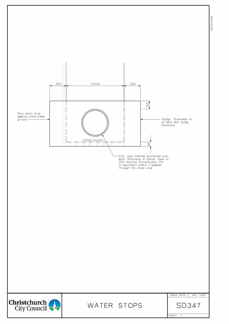
1
WATER STOPS SD347
Trench
Trench bottom.
Concrete.
15 MPa 150 slump
150mm Thickness of
300 300
80
150
through the water stop.
or equivalent where it passes
250 microns Polyethylene film
6mm thickness of Denso Tape or
PVC pipe shall be protected with
DEC 2009
ground.
against undisturbed
Pour water stop
DS
03470
1B
ISSUE DATE
SHEET

1
TO STORMWATER PIPES
DIRECT CONNECTIONSSD361
Diameter
Nominal SidelinePipe Diameter
Minimum Main
100
150
200
300
375
225
375
450
525
675
825
225/250
450
525
975
975
1050
1350
1600
1800
1950
600/675
750
825/900
1050 2100
SQUARE RADIAL DIRECT CONNECTIONS:
see note 8
Short pipes
Std. RCRR or ceramic socket short.
of main pipe.
above/below, top/bottom
150 all round, but not to extend
30°
30°
similar trimmed to suit
PVC Manhole starter or
D10 stirrup.
150 Min.
Trim pipe
of main pipe
of top and bottom
be between 30°
connection to
Drill hole for
mortar
Epoxy
mortar
Epoxy
MAR 2013
half the internal diameter of main pipe.
11. Diameter of sideline pipe shall be less than
with a manhole or shallow sump, but not a deep sump.
upstream end. That is the sideline shall terminate
cleaning the sideline is easily obtainable at the
the sideline is less than 10m long, and access for
and normally shall only be used where
10. Direct connections must be approved by the Engineer,
9. Sidelines shall be tested.
with standard detail plan SD341.
8. Sidelines shall have yield joints in accordance
coated before concrete corbel is poured.
7. Main pipe surface shall be roughened and grout
thoroughly compacted AP40 metal.
6. Main pipe backfill under sideline shall be
and the sideline laid.
and shall be fully cured before the corbel is poured
the manufacturer's recommendations,
5. Epoxy mortar shall be applied strictly according to
thirds of the internal diameter of main pipe.
4. Maximum diameter of cut-in hole shall be less than two
than 300mm from collar or end of pipe.
3. Outside edge of main pipe cut-in hole shall be not less
on plastic mains.
2. Direct connections of this type are not permitted
more than one connection per main pipe.
main pipes other than reinforced concrete;
1. Special design required for :
NOTES:
DS
03610
1C
ISSUE DATE
SHEET
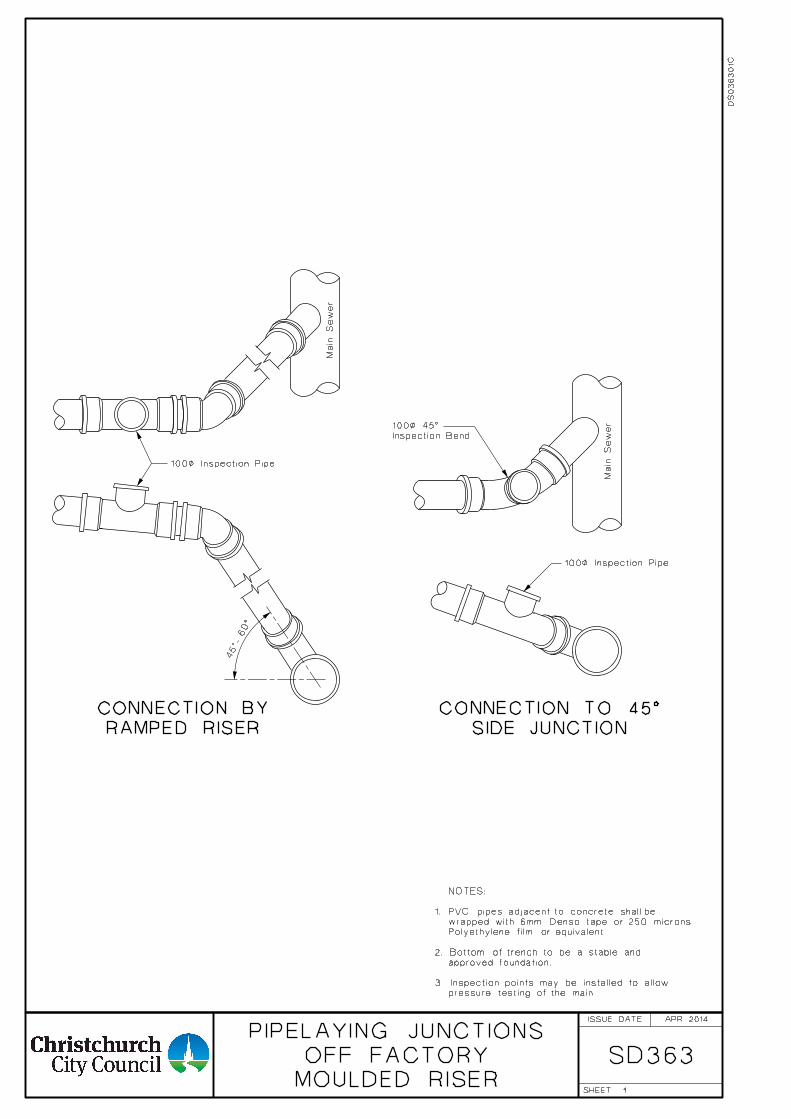
1
SD363MOULDED RISER
OFF FACTORY
PIPELAYING JUNCTIONSAPR 2014
DS
03630
1C
NOTES:
1. PVC pipes adjacent to concrete shall be
wrapped with 6mm Denso tape or 250 microns
Polyethylene film or equivalent.
2. Bottom of trench to be a stable and
approved foundation.
3. Inspection points may be installed to allow
pressure testing of the main.
ISSUE DATE
SHEET
SIDE JUNCTION
CONNECTION TO 45°
Inspection Bend
100< 45°
Main Se
wer
100< Inspection Pipe
Main Se
wer
100< Inspection Pipe
RAMPED RISER
CONNECTION BY
45°- 60°
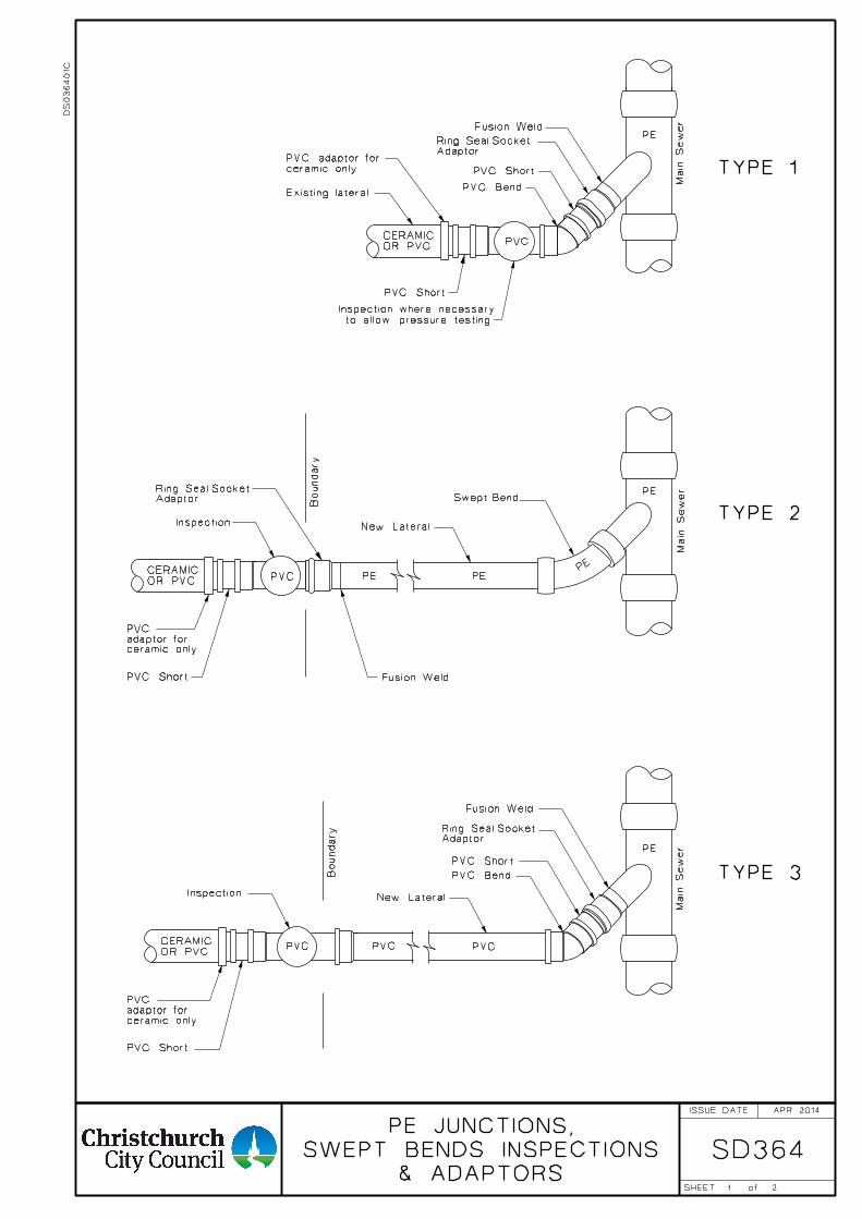
1
SD364& ADAPTORS
SWEPT BENDS INSPECTIONS
PE JUNCTIONS,
Main Se
wer
Main Se
wer
TYPE 2
TYPE 1
Swept Bend
Inspection
Existing lateral
New Lateral
PVC
PVC Bend
PVC
Main Se
wer
TYPE 3
New Lateral
PVC Bend
PVCPVC
Inspection
PVC
AdaptorRing Seal Socket
AdaptorRing Seal Socket
Fusion Weld
PVC Short
OR PVC
CERAMIC
ceramic onlyPVC adaptor for
OR PVC
CERAMIC
PVC Short
AdaptorRing Seal Socket
OR PVC
CERAMIC
PVC Short
Fusion Weld
PE
PE
PE
PEPE
PE
ceramic onlyadaptor forPVC
PVC Short
ceramic onlyadaptor forPVC
2
Fusion Weld
Boundary
Boundary
to allow pressure testing.
Inspection where necessary
PVC Short
DS
03640
1C
APR 2014ISSUE DATE
SHEET of
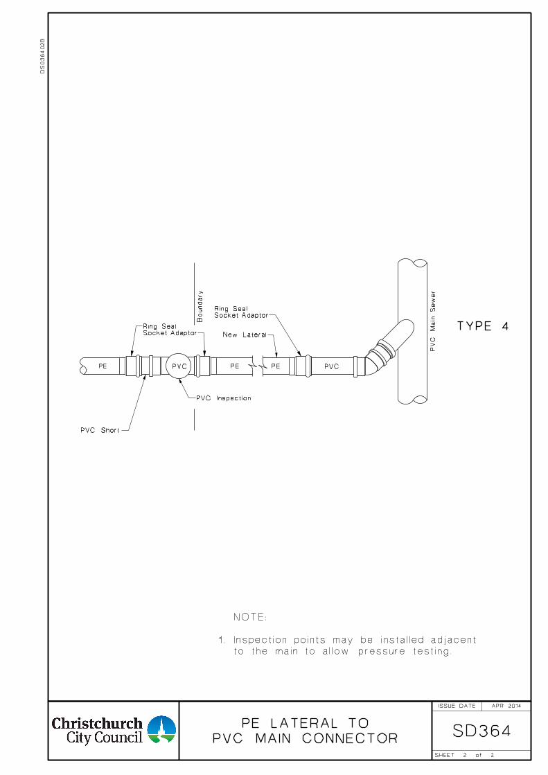
SD364
New Lateral
PVC
PVC Short
PEPE
2
TYPE 4
PE
Socket AdaptorRing Seal
PVC Inspection
Socket AdaptorRing Seal
PVC
PV
C
Main Se
wer
2
Boundary
PVC MAIN CONNECTOR
PE LATERAL TO
APR 2014
to the main to allow pressure testing.
1. Inspection points may be installed adjacent
NOTE:
DS
03640
2B
ISSUE DATE
SHEET of

1
CONCRETE HEADWALLS SD371
No. of A, B & C Rods
20
20
16
12
10
10
Rods <
A, B & C
TABLE 2
min
No.
4
6
8
10
12
14
crushed metal
50 depth of
TYPE 1 HEADWALL
TYPE 2 HEADWALL
TYPE 3 HEADWALL
Headwalls "W"
Minimum Width of
"W"
3 x "D"
"D" + 1800
"D"
3200
2900
2500
1800
1400
1000
(mm)
up to
"W"
80 Fillet
80 Fillet
TABLE 1
2400
2100
1800
1500
1200
900
up to
H
1200
1050
900
820
680
500
min
L
2000
1800
1600
1300
1050
750
S
230
200
180
180
180
180
T
K
T
W
D
D
H
W
TT
S
T
W
T
L L
T
TH
D
H
into hard bottom.
be at least 150
of base to
Underside
100 100
Up to
900<
Greater
than
900<
Bottom
Hard
slope exceeds 1:3
Special Design when
plan
haunching
of conc.
to height
Conc. cradle
100
Downstream Upstream
max
T T
L L25
otherwise specified.
6. Pipe ends shall be plain unless
than 1200mm special design shall apply.
5. For pipes with diameter greater
joint shall be within 1.3m.
for pipes 900< or less, a second yield
be adjacent to the headwall and
4. One yield joint (see SD341) shall
actual width.
reinforcing shall correspond to
3. If "W" exceeds the minimum,
slump.
2. Concrete shall be 25 MPa 75mm
satisfactory.
is 200 or less otherwise type 2 is
1. Type 1 headwall required if "K"
NOTES:
FEB 2002
2
DS
03710
1A
ISSUE DATE
SHEET of
TYPE 3
REINFORCING DETAILS
D10-300
D12-230
D10-300
D10-300
L 2
L
2
with Table 1 & 2
Rods in accordance
**
A
Rods
A D12
-230 Rods
D10-300
B
Rods
B D12
-230 Rods
D12-
230Rods
C
Rods
C
300
D10-
* ** *
* ** ** ** *
TYPE 1 & 2
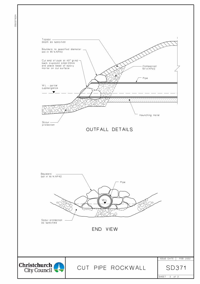
2
CUT PIPE ROCKWALL SD371
W.L.
Pipe
set in M/4:AP40
Boulders
END VIEW
as specified
Scour protection
Haunching metal
mortar on cut surface
and place bead of epoxy
back exposed steel 20mm
Cut end of pipe at 45° grind
protection
Scour
Pipe
submergance
W.L. - partial
M/4:AP40
Compacted
OUTFALL DETAILS
set in M/4:AP40
Boulders to specified diameter
depth as specified
Topsoil
FEB 2002
2
DS
03710
2A
ISSUE DATE
SHEET of
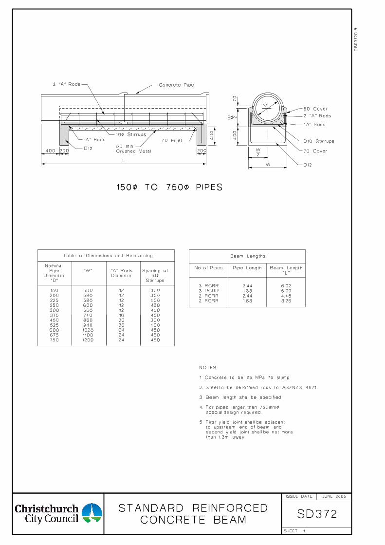
1
CONCRETE BEAM
STANDARD REINFORCEDSD372
Table of Dimensions and Reinforcing
"A" Rods
Diameter
12
12
12
12
12
16
750
675
600
525
450
1200
1100
1020
940
860
24
24
24
20
20
450
450
450
400
300
450
450
450
400
300
300
Stirrups
10<
Spacing of
Beam Length
"L"
6.92
5.09
4.48
3.26
No. of Pipes
3 RCRR
3 RCRR
2 RCRR
2 RCRR
Pipe Length
2.44
1.83
2.44
1.83
Beam Lengths
375
300
250
225
200
150
"D"
Diameter
Pipe
Nominal
"W"
500
580
580
600
660
740
70 Fillet
Concrete Pipe
D12
10< Stirrups
Crushed Metal
50 min
50 Cover
D10 Stirrups
70 Cover
D12W
70
400
400 200 200
L
D
400
150< TO 750< PIPES
W 2
W2
2 "A" Rods
"A" Rods
2 "A" Rods
"A" Rods
than 1.3m away.
second yield joint shall be not more
to upstream end of beam and
5. First yield joint shall be adjacent
special design required.
4. For pipes larger than 750mm<
3. Beam length shall be specified.
2. Steel to be deformed rods to AS/NZS 4671.
1. Concrete to be 25 MPa 75 slump.
NOTES:
JUNE 2005
DS
03720
1B
ISSUE DATE
SHEET

1 TYPE B AND TYPE C
CHAMBERS
STANDARD INSPECTION
SD375
520
680
700
720
820380
380
150
150
150 150 400
520
150
150
150 150
680
375< max
450< max
30
20
010
00
max.
70
520
30
20
010
00
max.
100
600
Flow Flow Flow Flow
as per SD301/3
Frame & Cover
Corner sump
TYPE B TYPE C
SECTION TYPE B SECTION TYPE C
as per SD301/7
Frame & Cover
Standard Manhole
DEC 2009
NOTES:
1. Cast iron frames to be seated on cement sand mortar, and set in with
plant mix asphalt or mortar as required.
2. Yield joints shall be provided in accordance with plan SD341 except that
in all cases two yield joints and one short pipe shall be used.
3. General method of pipelaying, angle connections, corbels, etc. to be in
accordance with plan SD341.
4. Concrete work to comply with NZS 3109.
5. All concrete to be 40MPa.
DS
03750
1B
ISSUE DATE
SHEET
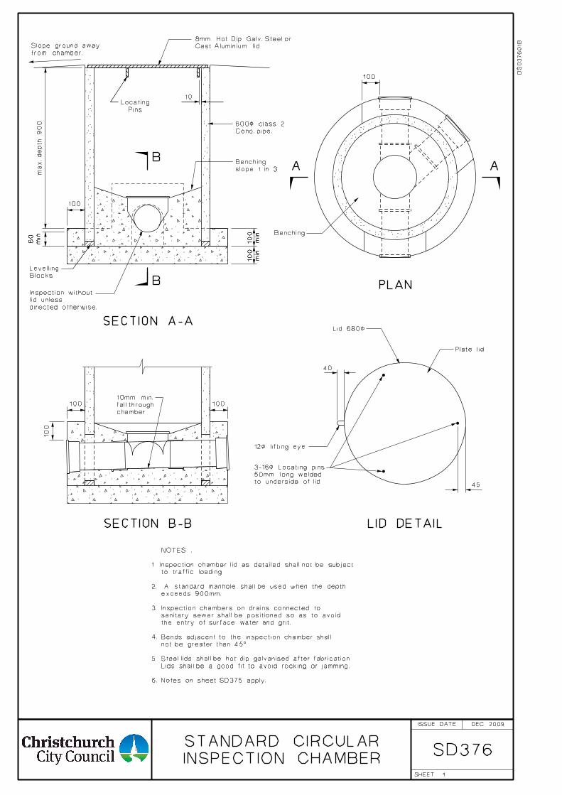
1
INSPECTION CHAMBER
STANDARD CIRCULARSD376
from chamber.
Slope ground away
slope 1 in 3
Benching
Benching
Blocks
Levelling
directed otherwise.
lid unless
Inspection without
12< lifting eye
to underside of lid.
50mm long welded
3-16< Locating pins
PLAN
LID DETAIL
A AB
B
min
60
min
100
min
100
100
10
100
100
40
45
100
100
SECTION A-A
SECTION B-B
Cast Aluminium lid
8mm Hot Dip Galv. Steel or
Plate lid
chamber
fall through
10mm min.
DEC 2009
NOTES :
to traffic loading.
exceeds 900mm.
3. Inspection chambers on drains connected to
sanitary sewer shall be positioned so as to avoid
the entry of surface water and grit.
4. Bends adjacent to the inspection chamber shall
not be greater than 45°.
5. Steel lids shall be hot dip galvanised after fabrication.
Lids shall be a good fit to avoid rocking or jamming.
6. Notes on sheet SD375 apply.
max. depth 900
1. Inspection chamber lid as detailed shall not be subject
2. A standard manhole shall be used when the depth
Lid 680<
DS
03760
1B
Conc. pipe.
600< class 2
Pins
Locating
ISSUE DATE
SHEET
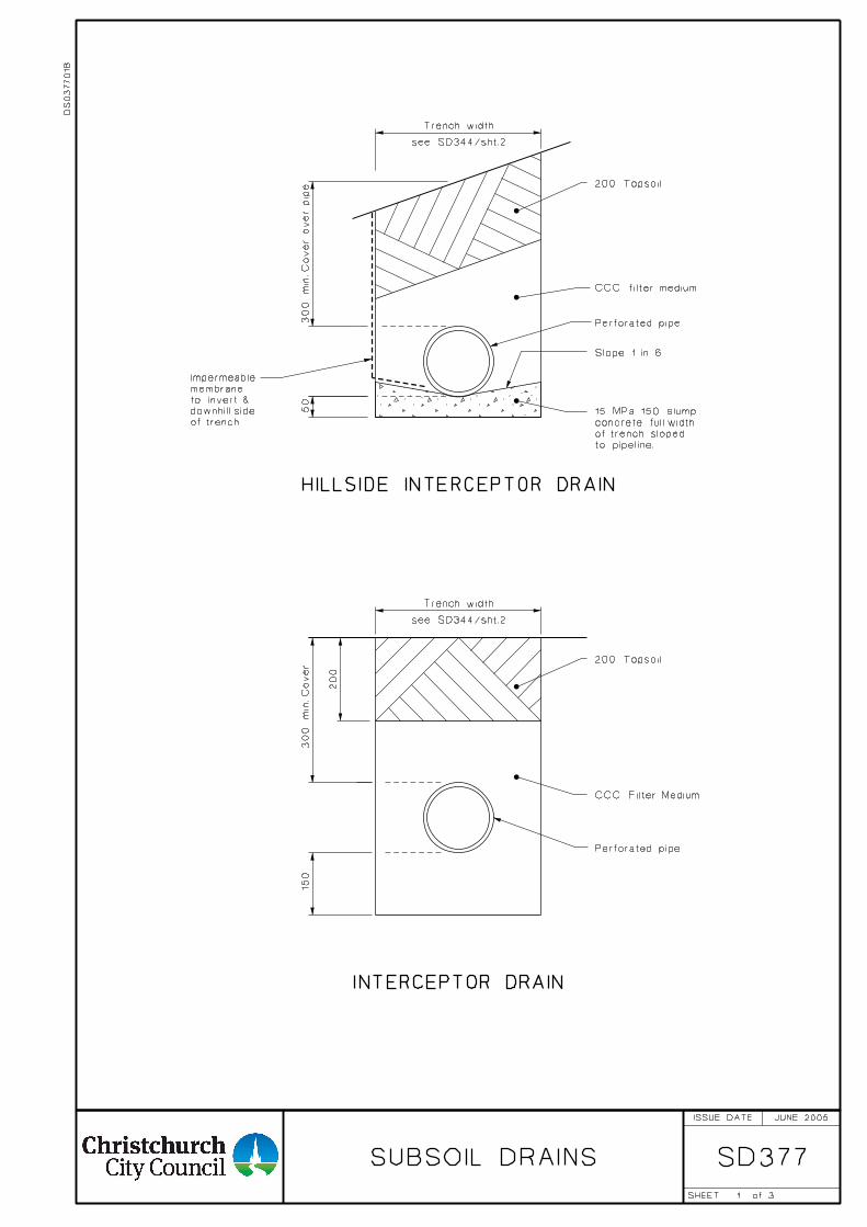
1
SD377SUBSOIL DRAINS
50
Trench width
see SD344/sht.2
300
min. C
over over pip
e
Slope 1 in 6
200 Topsoil
300
min. C
over
Trench width
see SD344/sht.2
200 Topsoil
150
HILLSIDE INTERCEPTOR DRAIN
INTERCEPTOR DRAIN
of trench
downhill side
to invert &
membrane
Impermeable
to pipeline.
of trench sloped
concrete full width
15 MPa 150 slump
Perforated pipe
Perforated pipe200
3
CCC filter medium
JUNE 2005
CCC Filter Medium
DS
03770
1B
ISSUE DATE
SHEET of
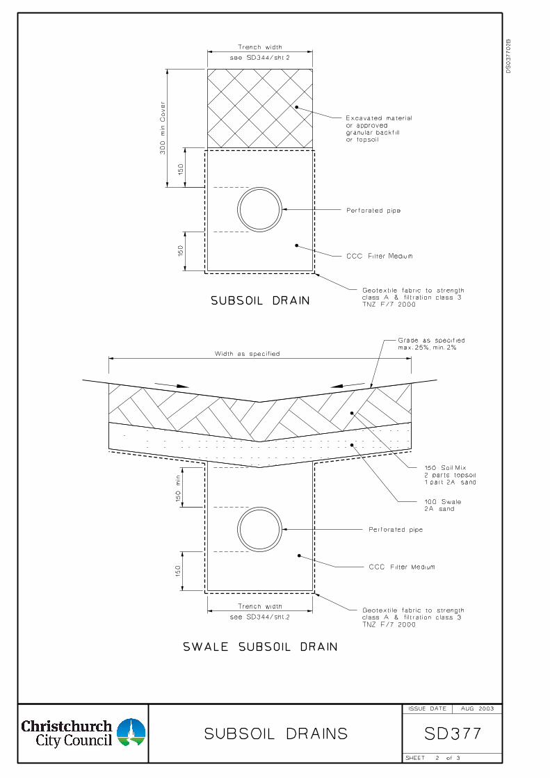
2
SD377SUBSOIL DRAINS
300
min. C
over
150
Trench width
see SD344/sht.2
150
min.
150
Trench width
see SD344/sht.2
TNZ F/7 2000
class A & filtration class 3
Geotextile fabric to strength
SWALE SUBSOIL DRAIN
or topsoil
granular backfill
or approved
Excavated material
SUBSOIL DRAIN
max. 25%, min. 2%
Grade as specified
150
Width as specified
1 part 2A sand
2 parts topsoil
150 Soil Mix
2A sand
100 Swale
Perforated pipe
Perforated pipe
AUG 2003
TNZ F/7 2000
class A & filtration class 3
Geotextile fabric to strength
3
CCC Filter Medium
CCC Filter Medium
DS
03770
2B
ISSUE DATE
SHEET of
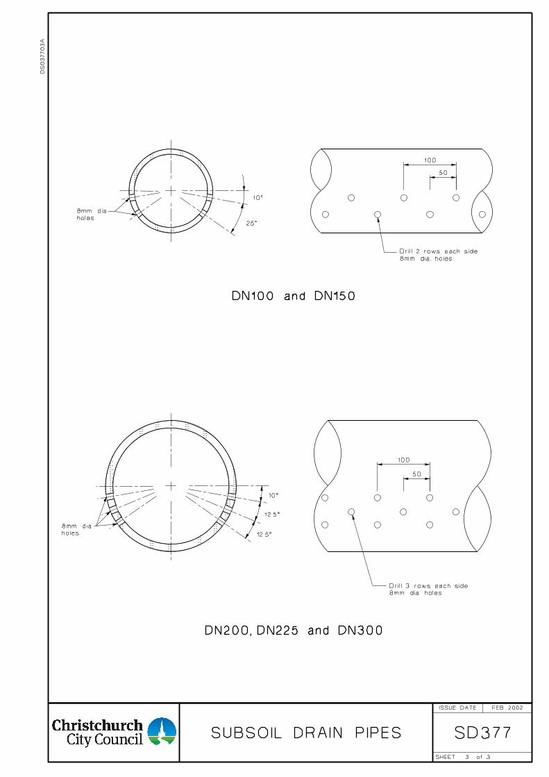
3
SD377SUBSOIL DRAIN PIPES
12.5°
10°
12.5°
10°
DN100 and DN150
DN200, DN225 and DN300
8mm dia. holes
Drill 2 rows each side
8mm dia. holes
Drill 3 rows each side
holes
8mm dia
holes
8mm dia
FEB 2002
50
100
100
50
3
DS
03770
3A
ISSUE DATE
SHEET of
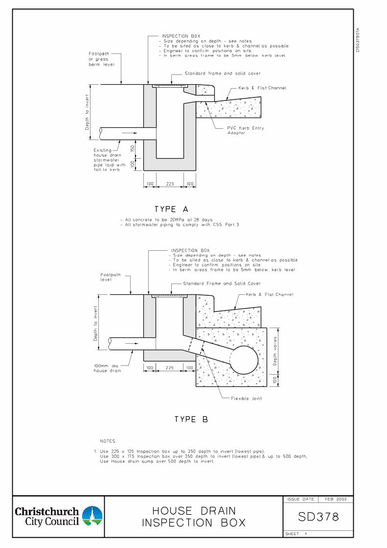
1
INSPECTION BOX
HOUSE DRAINSD378
TYPE B
level
Footpath
Standard Frame and Solid Cover
Kerb & Flat Channel.
Standard frame and solid cover.
Kerb & Flat Channel
Adaptor
PVC Kerb Entry
fall to kerb.
pipe laid with
stormwater
house drain
Existing
Flexible Joint
- All stormwater piping to comply with CSS Part 3
- All concrete to be 20MPa at 28 days
TYPE A
berm level
or grass
Footpath
house drain
100mm dia
Use House drain sump over 500 depth to invert.
Use 300 x 175 Inspection box over 350 depth to invert (lowest pipe) & up to 500 depth,
1. Use 225 x 125 Inspection box up to 350 depth to invert (lowest pipe),
NOTES:
- In berm areas frame to be 5mm below kerb level.
- Engineer to confirm positions on site.
- To be sited as close to kerb & channel as possible.
- Size depending on depth - see notes.
INSPECTION BOX
- In berm areas frame to be 5mm below kerb level.
- Engineer to confirm positions on site.
- To be sited as close to kerb & channel as possible.
- Size depending on depth - see notes.
INSPECTION BOX
FEB 2002
Depth to in
vert
Depth to in
vert
100225100
150
100
Depth varies
100
100 100225
DS
03780
1A
ISSUE DATE
SHEET
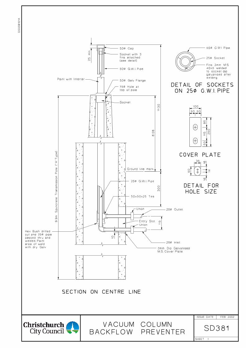
1
BACKFLOW PREVENTER
VACUUM COLUMNSD381
50< G.W.I. Pipe
25< Socket
welding
galvanised after
to socket dip
40x5 welded
Fins 3mm M.S.
50< Cap
(see detail)
fins attached
Socket with 3
50< G.W.I. Pipe
Paint with Intertar50< Galv. Flange
top of pole
75< Hole at
Socket
Ground line mark
25< G.W.I. Pipe
50x50x25 Tee
Union 25< Outlet
Entry Slot
Union
25< Inlet
M.S. Cover Plate
3mm Dip Galvanisedwith dry Galv.
area of weld
welded. Paint
passed thru and
out and 25< pipe
Hex. Bush drilled
ON 25< G.W.I. PIPE
DETAIL OF SOCKETS
COVER PLATE
HOLE SIZE
DETAIL FOR
115
50 50
100
50
115
85
250
36
18
14
18
50
25
min
11.3
0300
8.0
8
10
9.9
m
Spuncrete
Trans
missio
n Pole ("
A"Type)
SECTION ON CENTRE LINE
FEB 2002
DS
03810
1A
ISSUE DATE
SHEET
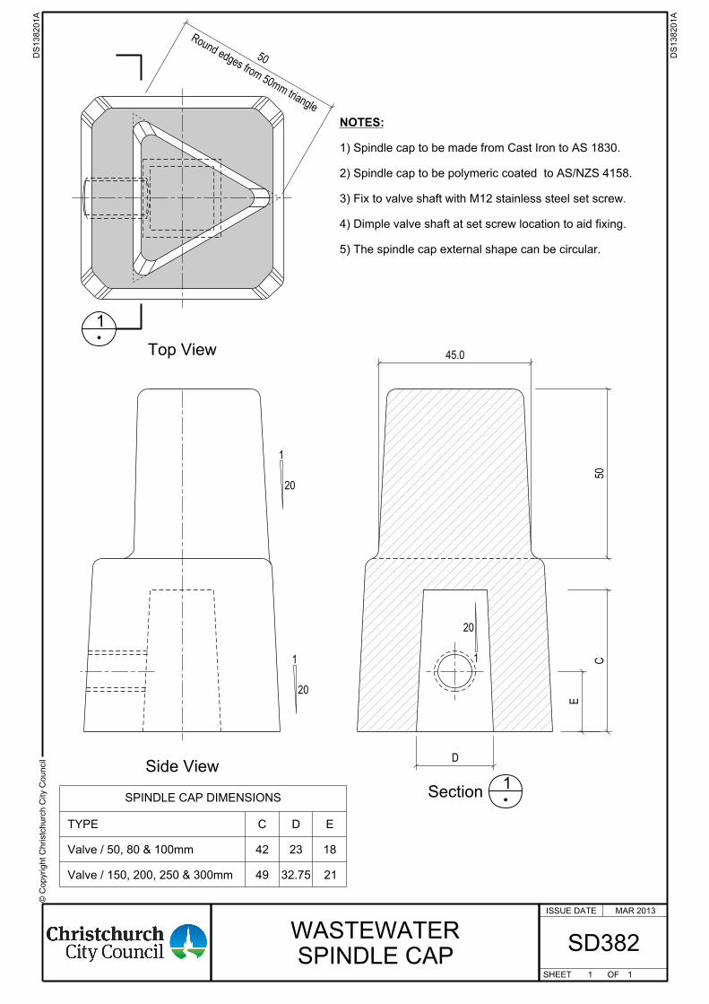
© C
opyright
Chr istc
hurc
h City C
ouncil
ISSUE DATE
SHEET OF
Top View
1
Section1
Side View
1
20
1
20
1
20
45.0
E
50
Round edges from 50mm triangle
50
SPINDLE CAP DIMENSIONS
Valve / 150, 200, 250 & 300mm
Valve / 50, 80 & 100mm
TYPE
49
42
C
21
18
E
32.75
23
D
C
D
5) The spindle cap external shape can be circular.
4) Dimple valve shaft at set screw location to aid fixing.
3) Fix to valve shaft with M12 stainless steel set screw.
2) Spindle cap to be polymeric coated to AS/NZS 4158.
1) Spindle cap to be made from Cast Iron to AS 1830.
NOTES:
1
WASTEWATER
SPINDLE CAPSD382
1
MAR 2013
DS138201
A
DS138201
A
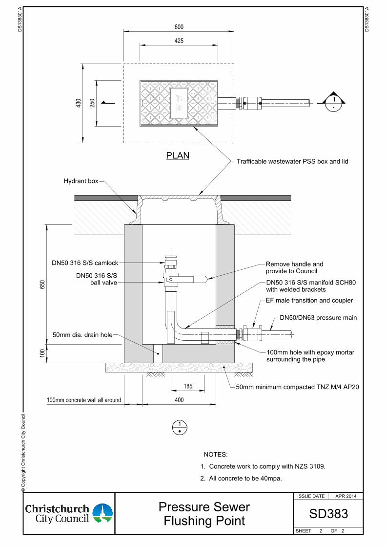
Trafficable wastewater PSS box and lid
Hydrant box
50mm minimum compacted TNZ M/4 AP20
surrounding the pipe
100mm hole with epoxy mortar
EF male transition and coupler
DN50/DN63 pressure main
provide to Council
Remove handle andDN50 316 S/S camlock
ball valve
DN50 316 S/S
with welded brackets
DN50 316 S/S manifold SCH80
50mm dia. drain hole
© C
opyright
Chr istc
hurc
h City C
ouncil
ISSUE DATE
SHEET OF
W W
425
250
PLAN
1
430
600
1
2. All concrete to be 40mpa.
1. Concrete work to comply with NZS 3109. NOTES:
650
100
185
400100mm concrete wall all around
2 2
DS138301
A
DS138301
A
SD383
APR 2014
Pressure Sewer
Flushing Point
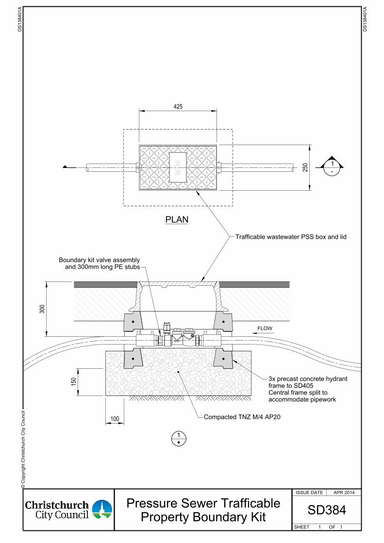
Trafficable wastewater PSS box and lid
and 300mm long PE stubs
Boundary kit valve assembly
150
100
300
accommodate pipework
Central frame split to
frame to SD405
3x precast concrete hydrant
Compacted TNZ M/4 AP20
© C
opyright
Chr istc
hurc
h City C
ouncil
ISSUE DATE
SHEET OF
W W
425
250
PLAN
1
1
FLOW
1 1
DS138401
A
DS138401
A
SD384
APR 2014
Pressure Sewer Trafficable
Property Boundary Kit

Christchurch City Council Civil Engineering Construction Standard Specification