chino, ca 91710 operation and maintenance … and maintenance 2 of 61 13822 oaks avenue chino, ca...
TRANSCRIPT
OPERATION and MAINTENANCE
1 of 61
13822 Oaks Avenue Chino, CA 91710 reedpumps.com (909) 287 - 2100
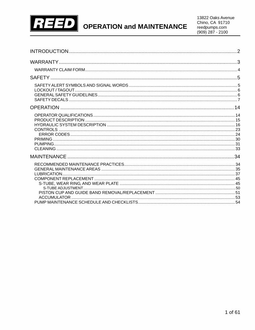
INTRODUCTION ........................................................................................................................ 2
WARRANTY ............................................................................................................................... 3
WARRANTY CLAIM FORM .................................................................................................................................... 4
SAFETY ..................................................................................................................................... 5
SAFETY ALERT SYMBOLS AND SIGNAL WORDS .............................................................................................. 5 LOCKOUT / TAGOUT ............................................................................................................................................. 6 GENERAL SAFETY GUIDELINES ......................................................................................................................... 6 SAFETY DECALS .................................................................................................................................................. 7
OPERATION ............................................................................................................................ 14
OPERATOR QUALIFICATIONS ........................................................................................................................... 14 PRODUCT DESCRIPTION .................................................................................................................................. 15 HYDRAULIC SYSTEM DESCRIPTION ............................................................................................................... 16 CONTROLS ......................................................................................................................................................... 23
ERROR CODES ............................................................................................................................................... 24 PRIMING .............................................................................................................................................................. 30 PUMPING ............................................................................................................................................................. 31 CLEANING ........................................................................................................................................................... 33
MAINTENANCE ....................................................................................................................... 34
RECOMMENDED MAINTENANCE PRACTICES ................................................................................................ 34 GENERAL MAINTENANCE AREAS .................................................................................................................... 35 LUBRICATION ...................................................................................................................................................... 37 COMPONENT REPLACEMENT .......................................................................................................................... 45
S-TUBE, WEAR RING, AND WEAR PLATE .................................................................................................... 45 S-TUBE ADJUSTMENT ................................................................................................................................................. 50
PISTON CUP AND GUIDE BAND REMOVAL/REPLACEMENT ..................................................................... 51 ACCUMULATOR .............................................................................................................................................. 53
PUMP MAINTENANCE SCHEDULE AND CHECKLISTS .................................................................................... 54
OPERATION and MAINTENANCE
2 of 61
13822 Oaks Avenue Chino, CA 91710 reedpumps.com (909) 287 - 2100
INTRODUCTION
This manual introduces the warranty policy, safe operation, safe maintenance, parts, and other aspects of the concrete pump. Reading and understanding this operation manual will help maximize performance and reliability, and help minimize dangers, improper operation, and repair costs. Contact REED Customer Service for additional replacement manuals. All safety guidelines, product descriptions, illustrations, and specifications found throughout this manual were in effect at the time the manual was released for printing. It should be noted; REED RESERVES THE RIGHT TO MAKE CHANGES IN DESIGN OR TO MAKE ADDITIONS TO OR IMPROVEMENTS IN THE PRODUCT WITHOUT IMPOSING ANY OBLIGATIONS UPON ITSELF TO INSTALL THEM ON PRODUCTS PREVIOUSLY MANUFACTURED. Everyone involved with the operation, maintenance, inspection, and repair of the concrete pump MUST READ and UNDERSTAND this manual and the accompanying Safety Manual.
OPERATION and MAINTENANCE
3 of 61
13822 Oaks Avenue Chino, CA 91710 reedpumps.com (909) 287 - 2100
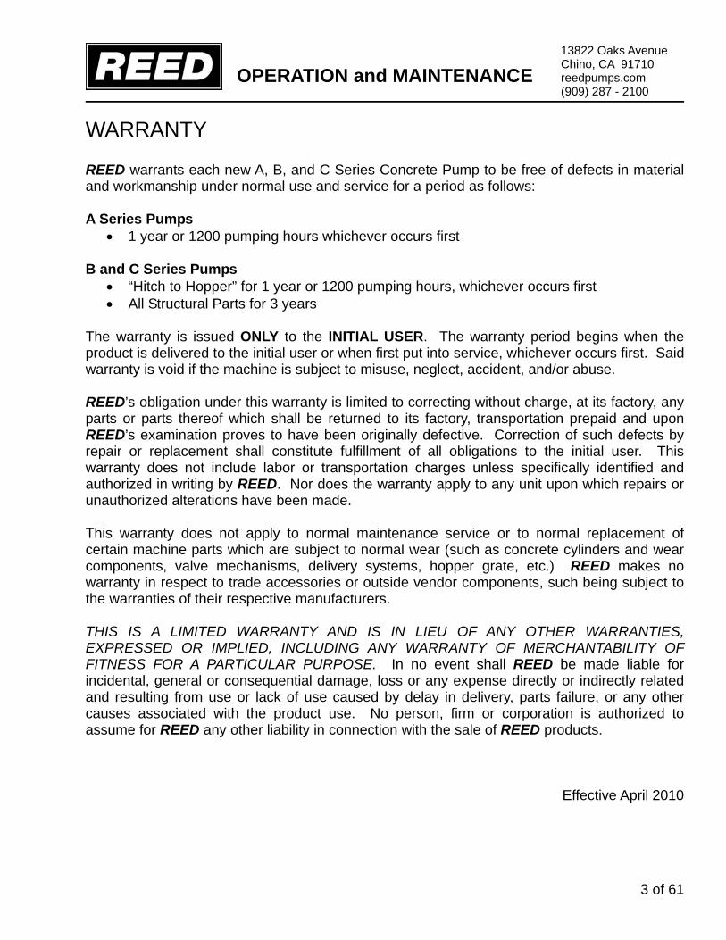
WARRANTY
REED warrants each new A, B, and C Series Concrete Pump to be free of defects in material and workmanship under normal use and service for a period as follows: A Series Pumps
1 year or 1200 pumping hours whichever occurs first B and C Series Pumps
“Hitch to Hopper” for 1 year or 1200 pumping hours, whichever occurs first All Structural Parts for 3 years
The warranty is issued ONLY to the INITIAL USER. The warranty period begins when the product is delivered to the initial user or when first put into service, whichever occurs first. Said warranty is void if the machine is subject to misuse, neglect, accident, and/or abuse. REED’s obligation under this warranty is limited to correcting without charge, at its factory, any parts or parts thereof which shall be returned to its factory, transportation prepaid and upon REED’s examination proves to have been originally defective. Correction of such defects by repair or replacement shall constitute fulfillment of all obligations to the initial user. This warranty does not include labor or transportation charges unless specifically identified and authorized in writing by REED. Nor does the warranty apply to any unit upon which repairs or unauthorized alterations have been made. This warranty does not apply to normal maintenance service or to normal replacement of certain machine parts which are subject to normal wear (such as concrete cylinders and wear components, valve mechanisms, delivery systems, hopper grate, etc.) REED makes no warranty in respect to trade accessories or outside vendor components, such being subject to the warranties of their respective manufacturers. THIS IS A LIMITED WARRANTY AND IS IN LIEU OF ANY OTHER WARRANTIES, EXPRESSED OR IMPLIED, INCLUDING ANY WARRANTY OF MERCHANTABILITY OF FITNESS FOR A PARTICULAR PURPOSE. In no event shall REED be made liable for incidental, general or consequential damage, loss or any expense directly or indirectly related and resulting from use or lack of use caused by delay in delivery, parts failure, or any other causes associated with the product use. No person, firm or corporation is authorized to assume for REED any other liability in connection with the sale of REED products.
Effective April 2010
OPERATION and MAINTENANCE
4 of 61
13822 Oaks Avenue Chino, CA 91710 reedpumps.com (909) 287 - 2100
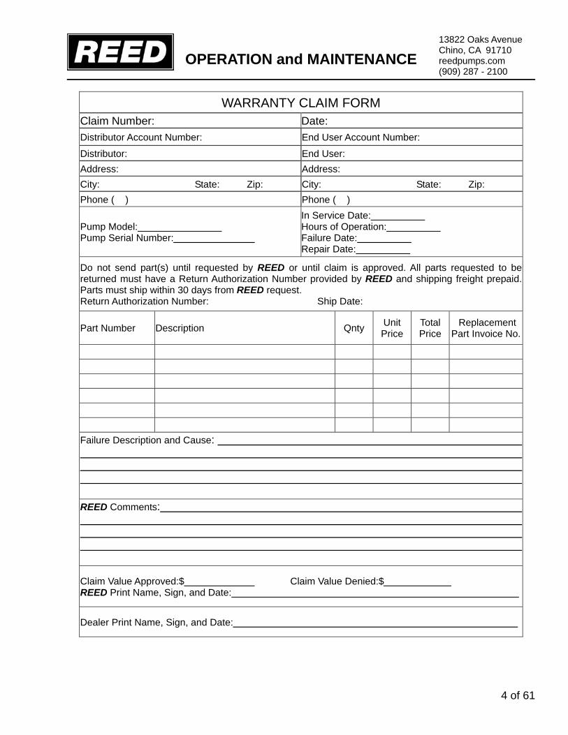
WARRANTY CLAIM FORM Claim Number: Date:
Distributor Account Number: End User Account Number:
Distributor: End User: Address: Address: City: State: Zip: City: State: Zip: Phone ( ) Phone ( )
Pump Model: Pump Serial Number:
In Service Date: Hours of Operation: Failure Date: Repair Date:
Do not send part(s) until requested by REED or until claim is approved. All parts requested to be returned must have a Return Authorization Number provided by REED and shipping freight prepaid. Parts must ship within 30 days from REED request. Return Authorization Number: Ship Date:
Part Number Description Qnty Unit Price
Total Price
Replacement Part Invoice No.
Failure Description and Cause:
REED Comments:
Claim Value Approved:$ Claim Value Denied:$ REED Print Name, Sign, and Date:
Dealer Print Name, Sign, and Date:
OPERATION and MAINTENANCE
5 of 61
13822 Oaks Avenue Chino, CA 91710 reedpumps.com (909) 287 - 2100
SAFETY Everyone involved with the operation, maintenance, inspection, and repair of the concrete pump MUST READ and UNDERSTAND this manual and the accompanying Safety Manual.
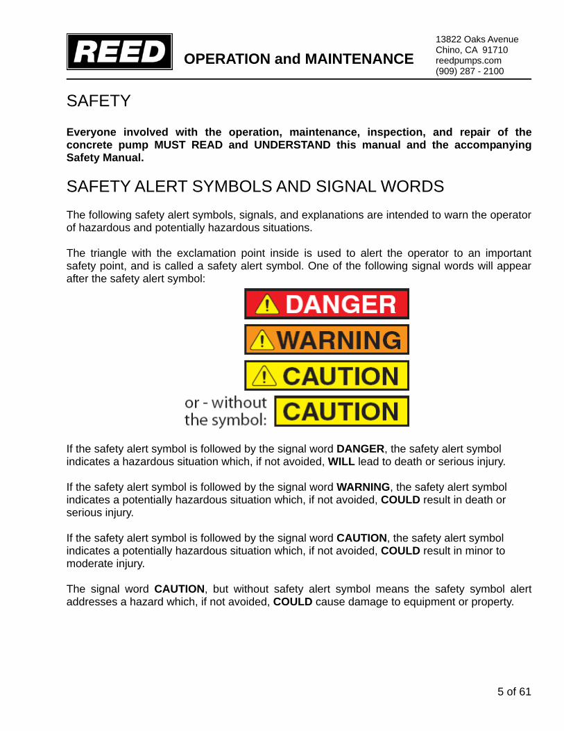
SAFETY ALERT SYMBOLS AND SIGNAL WORDS The following safety alert symbols, signals, and explanations are intended to warn the operator of hazardous and potentially hazardous situations. The triangle with the exclamation point inside is used to alert the operator to an important safety point, and is called a safety alert symbol. One of the following signal words will appear after the safety alert symbol:
If the safety alert symbol is followed by the signal word DANGER, the safety alert symbol indicates a hazardous situation which, if not avoided, WILL lead to death or serious injury. If the safety alert symbol is followed by the signal word WARNING, the safety alert symbol indicates a potentially hazardous situation which, if not avoided, COULD result in death or serious injury. If the safety alert symbol is followed by the signal word CAUTION, the safety alert symbol indicates a potentially hazardous situation which, if not avoided, COULD result in minor to moderate injury. The signal word CAUTION, but without safety alert symbol means the safety symbol alert addresses a hazard which, if not avoided, COULD cause damage to equipment or property.
OPERATION and MAINTENANCE
6 of 61
13822 Oaks Avenue Chino, CA 91710 reedpumps.com (909) 287 - 2100
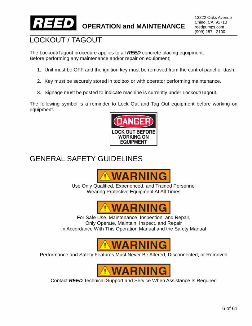
LOCKOUT / TAGOUT The Lockout/Tagout procedure applies to all REED concrete placing equipment. Before performing any maintenance and/or repair on equipment;
1. Unit must be OFF and the ignition key must be removed from the control panel or dash.
2. Key must be securely stored in toolbox or with operator performing maintenance.
3. Signage must be posted to indicate machine is currently under Lockout/Tagout. The following symbol is a reminder to Lock Out and Tag Out equipment before working on equipment.
GENERAL SAFETY GUIDELINES
Use Only Qualified, Experienced, and Trained Personnel
Wearing Protective Equipment At All Times
For Safe Use, Maintenance, Inspection, and Repair,
Only Operate, Maintain, Inspect, and Repair In Accordance With This Operation Manual and the Safety Manual
Performance and Safety Features Must Never Be Altered, Disconnected, or Removed
Contact REED Technical Support and Service When Assistance Is Required
OPERATION and MAINTENANCE
7 of 61
13822 Oaks Avenue Chino, CA 91710 reedpumps.com (909) 287 - 2100
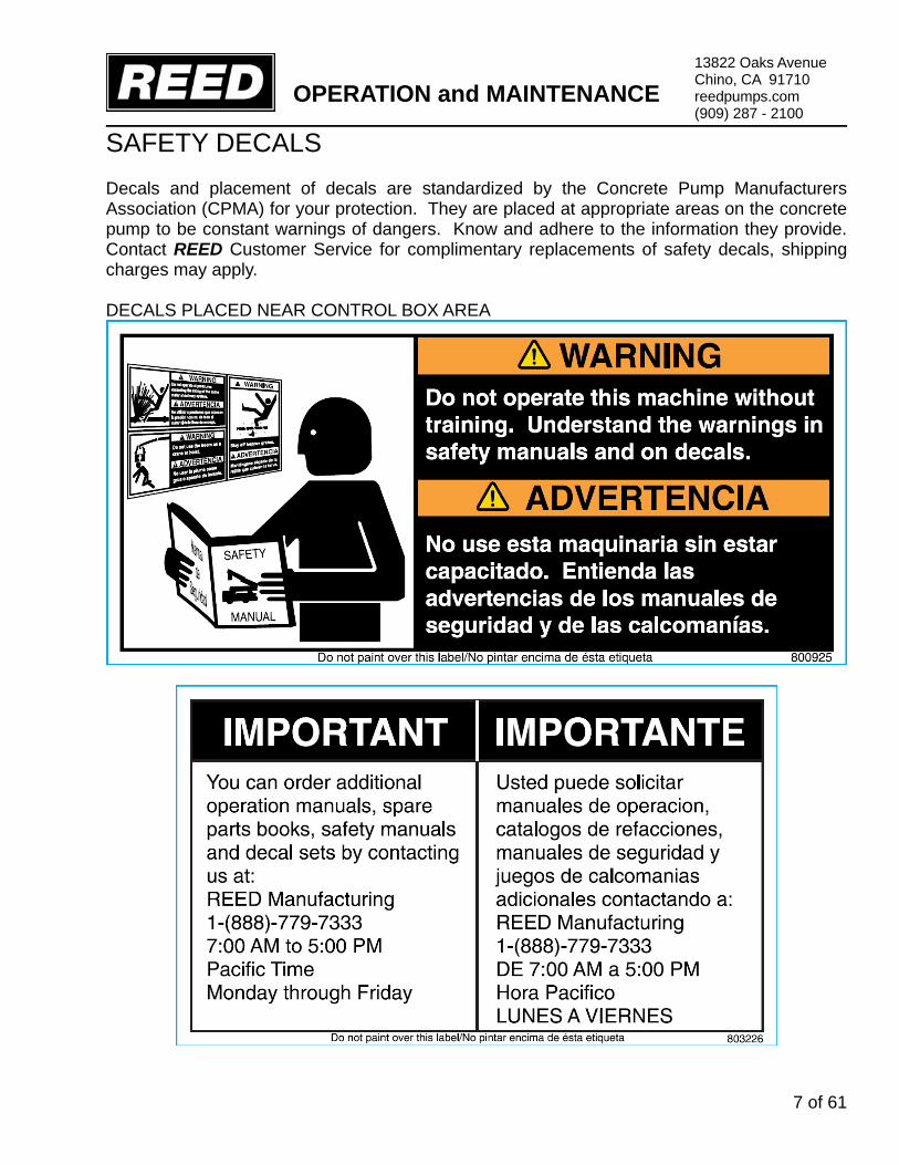
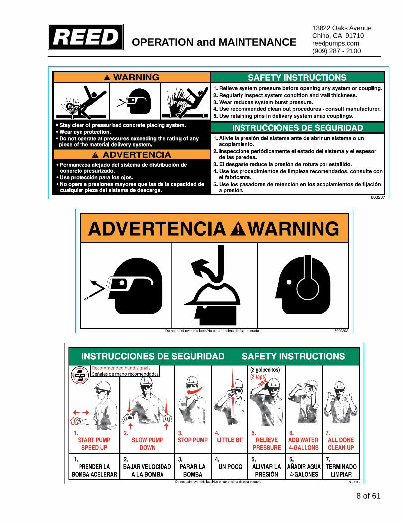
SAFETY DECALS Decals and placement of decals are standardized by the Concrete Pump Manufacturers Association (CPMA) for your protection. They are placed at appropriate areas on the concrete pump to be constant warnings of dangers. Know and adhere to the information they provide. Contact REED Customer Service for complimentary replacements of safety decals, shipping charges may apply. DECALS PLACED NEAR CONTROL BOX AREA
OPERATION and MAINTENANCE
8 of 61
13822 Oaks Avenue Chino, CA 91710 reedpumps.com (909) 287 - 2100
OPERATION and MAINTENANCE
9 of 61
13822 Oaks Avenue Chino, CA 91710 reedpumps.com (909) 287 - 2100
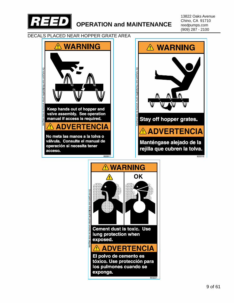
DECALS PLACED NEAR HOPPER GRATE AREA
OPERATION and MAINTENANCE
10 of 61
13822 Oaks Avenue Chino, CA 91710 reedpumps.com (909) 287 - 2100
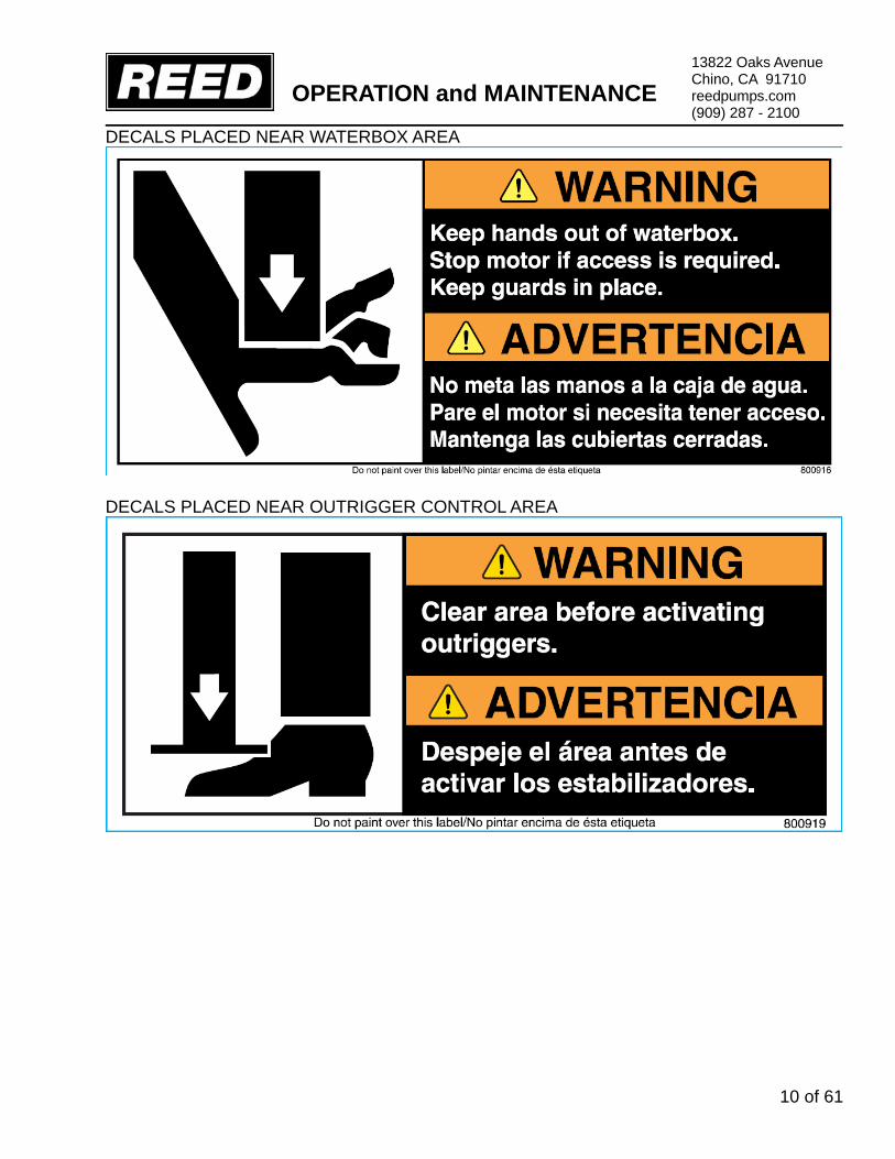
DECALS PLACED NEAR WATERBOX AREA
DECALS PLACED NEAR OUTRIGGER CONTROL AREA
OPERATION and MAINTENANCE
11 of 61
13822 Oaks Avenue Chino, CA 91710 reedpumps.com (909) 287 - 2100
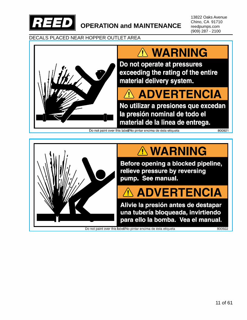
DECALS PLACED NEAR HOPPER OUTLET AREA
OPERATION and MAINTENANCE
12 of 61
13822 Oaks Avenue Chino, CA 91710 reedpumps.com (909) 287 - 2100
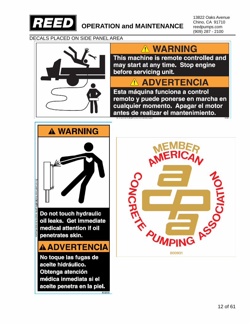
DECALS PLACED ON SIDE PANEL AREA

OPERATION and MAINTENANCE
13 of 61
13822 Oaks Avenue Chino, CA 91710 reedpumps.com (909) 287 - 2100
OPERATION and MAINTENANCE
14 of 61
13822 Oaks Avenue Chino, CA 91710 reedpumps.com (909) 287 - 2100
OPERATION
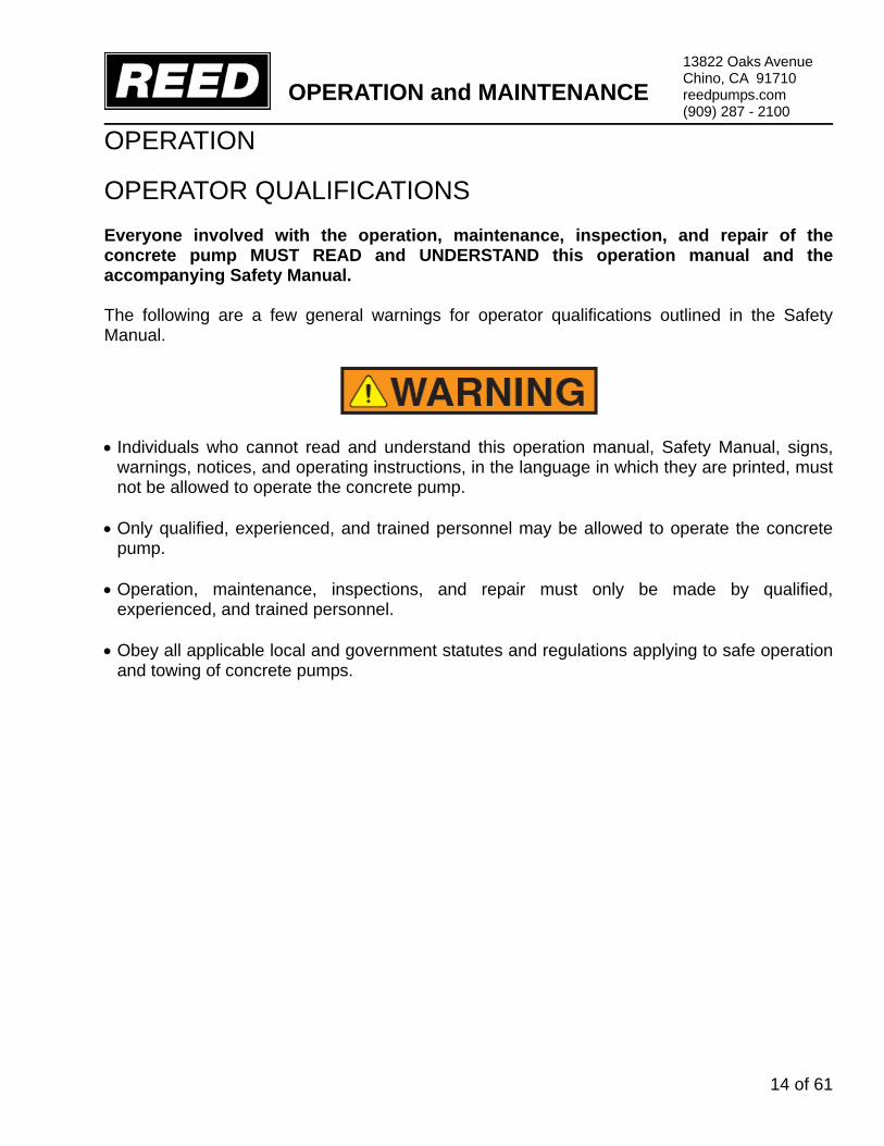
OPERATOR QUALIFICATIONS Everyone involved with the operation, maintenance, inspection, and repair of the concrete pump MUST READ and UNDERSTAND this operation manual and the accompanying Safety Manual. The following are a few general warnings for operator qualifications outlined in the Safety Manual.
Individuals who cannot read and understand this operation manual, Safety Manual, signs, warnings, notices, and operating instructions, in the language in which they are printed, must not be allowed to operate the concrete pump.
Only qualified, experienced, and trained personnel may be allowed to operate the concrete
pump. Operation, maintenance, inspections, and repair must only be made by qualified,
experienced, and trained personnel. Obey all applicable local and government statutes and regulations applying to safe operation
and towing of concrete pumps.
OPERATION and MAINTENANCE
15 of 61
13822 Oaks Avenue Chino, CA 91710 reedpumps.com (909) 287 - 2100
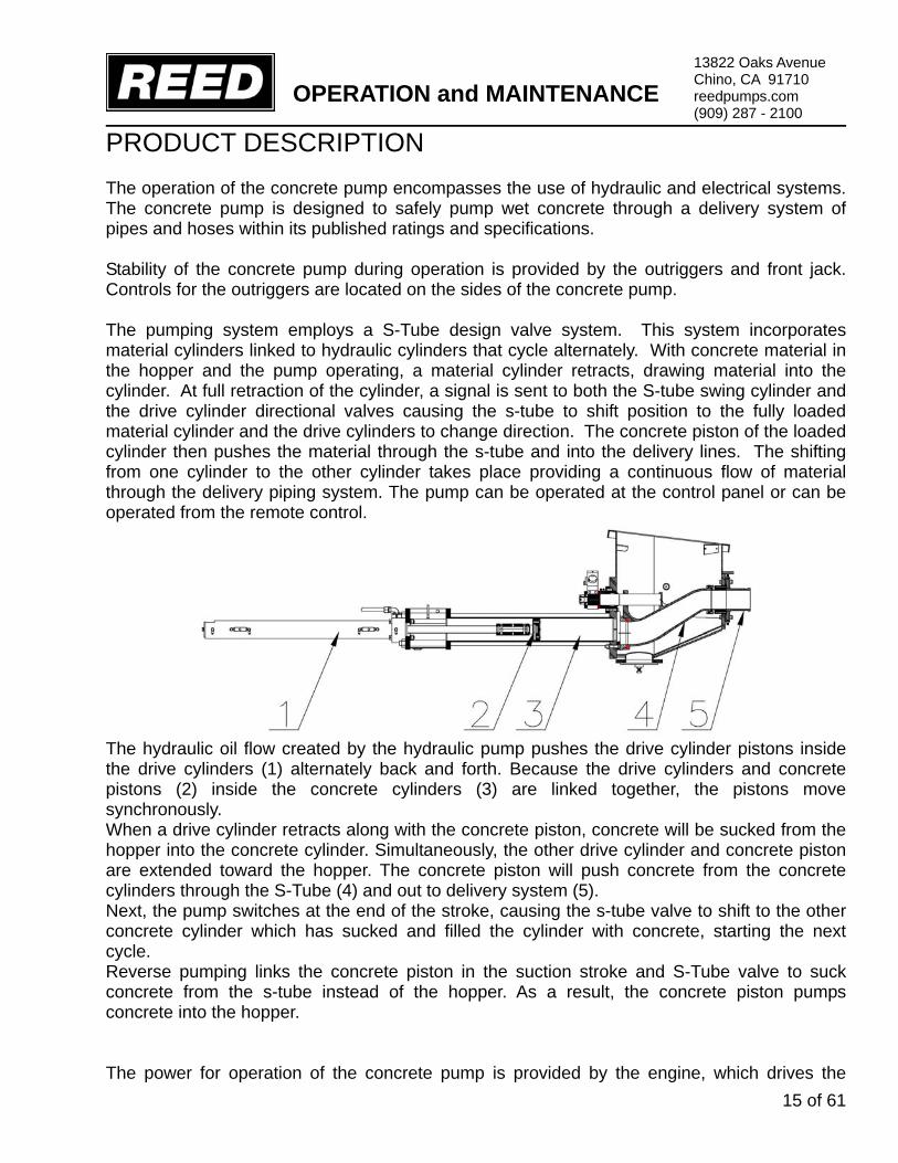
PRODUCT DESCRIPTION The operation of the concrete pump encompasses the use of hydraulic and electrical systems. The concrete pump is designed to safely pump wet concrete through a delivery system of pipes and hoses within its published ratings and specifications. Stability of the concrete pump during operation is provided by the outriggers and front jack. Controls for the outriggers are located on the sides of the concrete pump. The pumping system employs a S-Tube design valve system. This system incorporates material cylinders linked to hydraulic cylinders that cycle alternately. With concrete material in the hopper and the pump operating, a material cylinder retracts, drawing material into the cylinder. At full retraction of the cylinder, a signal is sent to both the S-tube swing cylinder and the drive cylinder directional valves causing the s-tube to shift position to the fully loaded material cylinder and the drive cylinders to change direction. The concrete piston of the loaded cylinder then pushes the material through the s-tube and into the delivery lines. The shifting from one cylinder to the other cylinder takes place providing a continuous flow of material through the delivery piping system. The pump can be operated at the control panel or can be operated from the remote control.
The hydraulic oil flow created by the hydraulic pump pushes the drive cylinder pistons inside the drive cylinders (1) alternately back and forth. Because the drive cylinders and concrete pistons (2) inside the concrete cylinders (3) are linked together, the pistons move synchronously. When a drive cylinder retracts along with the concrete piston, concrete will be sucked from the hopper into the concrete cylinder. Simultaneously, the other drive cylinder and concrete piston are extended toward the hopper. The concrete piston will push concrete from the concrete cylinders through the S-Tube (4) and out to delivery system (5). Next, the pump switches at the end of the stroke, causing the s-tube valve to shift to the other concrete cylinder which has sucked and filled the cylinder with concrete, starting the next cycle. Reverse pumping links the concrete piston in the suction stroke and S-Tube valve to suck concrete from the s-tube instead of the hopper. As a result, the concrete piston pumps concrete into the hopper. The power for operation of the concrete pump is provided by the engine, which drives the
OPERATION and MAINTENANCE
16 of 61
13822 Oaks Avenue Chino, CA 91710 reedpumps.com (909) 287 - 2100
hydraulic pumps. All functions for operation of the concrete pump can be accomplished from the local controls mounted on the side of the unit. Optional hand-held cable or radio remotes enable the pump to be operated away from a remote distance.
HYDRAULIC SYSTEM DESCRIPTION The hydraulic system of the concrete pump consists of three separate circuits and although integrated, each is designed to perform a particular function within the operation of the concrete pump. The three circuits utilized are: Main Pump Circuit Controls operation of the hydraulic drive cylinders. S-Tube Shift Circuit Controls operation of shifting the s-tube from one material cylinder to the other. Auxiliary Circuit Controls the operation of the agitator and other auxiliary equipment. For the purpose of making the operation of each circuit easier to understand, they are being described separately. MAIN PUMP CIRCUIT The main hydraulic pump is a variable displacement axial piston pump of swashplate design. The pistons run along the swashplate which is capable of being tilted. This tilting changes the angle of the swashplate and thus the stroke length of the pistons, which in turn varies the displacement of fluid. The larger the angle of the swashplate, the greater the flow of fluid. The angle of the swashplate is varied by the volume control that works in conjunction with the load sense feature of this pump.
The main hydraulic pump is driven directly by the engine or electric motor. When the engine is running, PUMP switch in the OFF position and the VOLUME control minimized, there is no demand placed on the pump. This is referred to as the pump being de-stroked, meaning, it is only producing a minimal amount of flow to enable the lubrication of the pump. This lubrication exists regardless of whether the engine is at idle or maximum RPM.
The main pump circuit is equipped with a manifold that is drilled and ported to accommodate the relief valve, check valve, flow control and the pilot operated directional valve. The cycle valve is a directional spool valve with electro hydraulic solenoid operation. Its purpose is to direct the flow of oil from the main hydraulic pump to one or the other hydraulic drive cylinders.
To energize the pump circuit, use the adjustable throttle control to set the engine speed at maximum RPM. Open the VOLUME control to any range from 0 to FULL. In so doing, the load
OPERATION and MAINTENANCE
17 of 61
13822 Oaks Avenue Chino, CA 91710 reedpumps.com (909) 287 - 2100
sense is alerted to the demand and places the pump on stroke. The pump will now produce the flow in proportion to the amount by which the volume control has been opened. Since the PUMP switch is OFF, the flow from the hydraulic pump is fed to the main directional valve, thru the valve, and then returns to the hydraulic tank.
To energize the cycling circuit, the PUMP switch must be ON. When this is done, an electrical signal is generated which in turn energizes the coils of the main directional pilot valve and also activates the S-Tube directional valve.
The material pumping action is the result of the two material cylinders cycling on an alternate basis. This alternating cycling is controlled by an electrical signal that is generated by the proximity sensors located in the flush box at the end of each material cylinder’s suction or retraction stroke.
As the piston coupler passes under the proximity sensor, it generates an electrical input signal that is sent to the logic controller, designed to control the alternating action of the material cylinders and to synchronize the movement of the s-tube. The output signal from the logic controller is used to energize the coils of the main directional pilot valve as well as that of the s-tube directional valve. As protection to the main pump circuit against excessive pressure, a relief valve has been installed and set. Thus when the system pressure reaches the maximum factory settings, the relief valve opens directing the oil back to the tank.
OPERATION and MAINTENANCE
18 of 61
13822 Oaks Avenue Chino, CA 91710 reedpumps.com (909) 287 - 2100
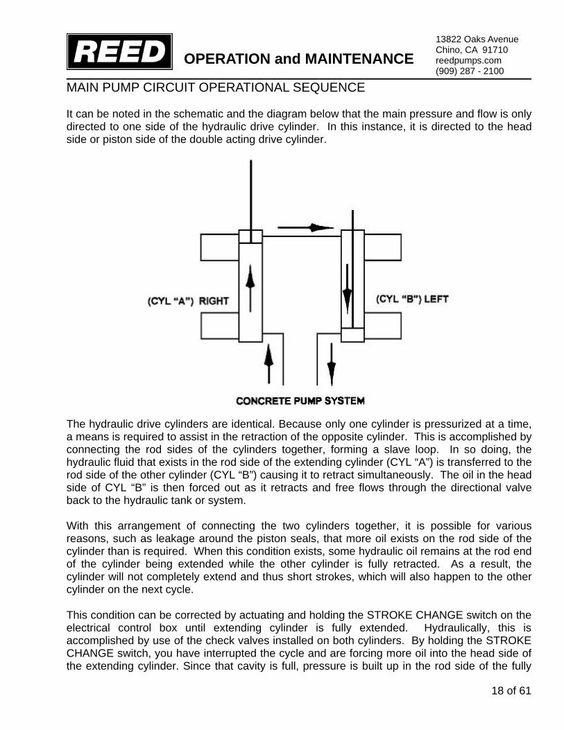
MAIN PUMP CIRCUIT OPERATIONAL SEQUENCE It can be noted in the schematic and the diagram below that the main pressure and flow is only directed to one side of the hydraulic drive cylinder. In this instance, it is directed to the head side or piston side of the double acting drive cylinder.
The hydraulic drive cylinders are identical. Because only one cylinder is pressurized at a time, a means is required to assist in the retraction of the opposite cylinder. This is accomplished by connecting the rod sides of the cylinders together, forming a slave loop. In so doing, the hydraulic fluid that exists in the rod side of the extending cylinder (CYL “A”) is transferred to the rod side of the other cylinder (CYL “B”) causing it to retract simultaneously. The oil in the head side of CYL “B” is then forced out as it retracts and free flows through the directional valve back to the hydraulic tank or system. With this arrangement of connecting the two cylinders together, it is possible for various reasons, such as leakage around the piston seals, that more oil exists on the rod side of the cylinder than is required. When this condition exists, some hydraulic oil remains at the rod end of the cylinder being extended while the other cylinder is fully retracted. As a result, the cylinder will not completely extend and thus short strokes, which will also happen to the other cylinder on the next cycle.
This condition can be corrected by actuating and holding the STROKE CHANGE switch on the electrical control box until extending cylinder is fully extended. Hydraulically, this is accomplished by use of the check valves installed on both cylinders. By holding the STROKE CHANGE switch, you have interrupted the cycle and are forcing more oil into the head side of the extending cylinder. Since that cavity is full, pressure is built up in the rod side of the fully
OPERATION and MAINTENANCE
19 of 61
13822 Oaks Avenue Chino, CA 91710 reedpumps.com (909) 287 - 2100
retracted cylinder, which unseats the head-side check valve and forces the excess oil out of the slave loop and back to the tank. Once the extending cylinder has reached its full stroke, regular operation can continue. Short stroking can also occur from incorrect proximity sensor location or leaking check valves. S-TUBE CIRCUIT Since there is only one outlet for the pumping material, a means is required to transfer the material from the material cylinder to the outlet and into the delivery line. To accomplish this, an s-tube is installed in the hopper. Since there are two material cylinders and one s-tube, the s-tube must be shifted from one material cylinder to the other, whichever one is loaded with the pumping material. The s-tube shift hydraulic circuit is of the open center type, meaning that when the control valves are in the neutral position, the internal passages of the valves are open, allowing the hydraulic fluid to return to the tank. With the engine running the hydraulic pump is operating, producing a flow of oil which, with no control energized, will pass through the shift circuit on its way back to tank.
To meet the flow and pressure requirements of the shift circuit, one section of a tandem pump is used. Note: a single pump may be used if unit is not required for auxiliary equipment. The tandem hydraulic pump is of the gear pump design with a fixed displacement, meaning it is designed to constantly produce the same displacement at a pre-set maximum, depending on engine rpm. The tandem gear pump is directly connected to and driven through the main hydraulic pump. In addition to the hydraulic pump, the s-tube shift circuit consists of a manifold, an accumulator, solenoid valve cartridges, a solenoid directional valve, and 1 or 2 hydraulic shift cylinders. The following is offered to describe the function of each in the system.
S-TUBE CIRCUIT MANIFOLD Like the main hydraulic circuit, the shift circuit is also equipped with a manifold block. It contains an unloader cartridge, relief cartridge, solenoid valve cartridges, directional valve (solenoid or pilot operated) and an s-tube shift selector ball valve. Each of these components is designed to perform a particular function in the swing circuit as explained in the following descriptions:
RELIEF CARTRIDGE This cartridge is used to divert the pump flow from going to the accumulator once its capacity has been reached, directing it to free flow back to tank. It becomes operational when the unloader cartridge setting has been reached, acting as a dump valve. UNLOADER CARTRIDGE This pressure sensitive cartridge is used to protect the system from excessive pressure. It limits the amount of pressure being applied to the accumulator by hydraulically signaling the relief cartridge to open once the unloader setting has been reached. The unloader will also redirect the oil back to the accumulator when it senses a drop in system pressure,
OPERATION and MAINTENANCE
20 of 61
13822 Oaks Avenue Chino, CA 91710 reedpumps.com (909) 287 - 2100
when the hydraulic cylinder shifts for example.
SOLENOID VALVE CARTRIDGE There are two (2) of these cartridges used in the circuit. These cartridges, which may be referred to as dump valves, are designed into the circuit as SAFETY VALVES. Close-loop models utilize one (1) solenoid valve. Their purpose is to automatically relieve pressure from the shift circuit as commanded by the emergency stop circuit. At start up, the normally open cartridges are open to tank so the shift circuit can not build any pressure. When the emergency stop circuit is reset, an electrical signal is generated which energizes the solenoids, closing the cartridges and allowing the shift circuit to pressurize. When the emergency stop function is activated or the key switch turned off, the power is taken away from solenoids, causing the cartridges to open and dump shift circuit pressure back to tank.
SOLENOID DIRECTIONAL VALVE This valve is a directional control valve that is shifted by electronically activated solenoids. Its purpose is to direct the flow of oil stored in the accumulator to one or the other end of the shift cylinder based on the signal received by the logic controller that was generated by the proximity sensor.
S-TUBE SHIFT SELECTOR BALL VALVE This is a manual ball valve used to control the speed of the s-tube shift. With valve fully opened (CCW), the flow is unrestricted, causing a fast hard shift of the s-tube. When the valve is closed (CW), the shift is slower as the flow must now pass through an orifice. ACCUMULATOR
The accumulator is incorporated into the shift circuit to provide instant pressure and volume for the shifting of the s-tube, which cannot be obtained under normal circumstances. An accumulator is a hydraulic reservoir that retains the hydraulic fluid under high pressure. The accumulator contains a rubber bladder on the inside of the reservoir. The bladder is pre-charged with dry nitrogen. In the application of the shift circuit, the hydraulic fluid is pumped into the accumulator at a higher pressure than that inside the bladder. This compresses the bladder building up high pressure within the accumulator that is retained until released.
OPERATION and MAINTENANCE
21 of 61
13822 Oaks Avenue Chino, CA 91710 reedpumps.com (909) 287 - 2100
S-TUBE CIRCUIT OPERATIONAL SEQUENCE In the operational sequence of the shift circuit with the engine at full RPM, the tandem pump is producing its rated displacement. The flow is going through the system and is being dumped or directed back to the tank thru the solenoid cartridges of the s-tube circuit manifold.
When the HORN/RESET switch is placed to RESET, an electrical signal closes the solenoid valve or cartridges. When this occurs the hydraulic fluid is now directed to the accumulator where it starts compressing the bladder and building up pressure. When the pressure in the shift circuit reaches a setting of the unloader valve, the unloader valve activates causing the relief cartridge to open. The open relief valve now directs the oil flow from the pump back to the tank instead of continuing to pressurize the accumulator. A check valve retains the pressure in the swing circuit and prevents the fluid from going back into the pump line.
In the main pump circuit description it was described how an electrical signal was generated by the proximity sensor which was sent to the logic controller and used to control the alternating action of the hydraulic drive cylinders. This same signal is also used to shift the s-tube so that its movement is synchronized with that of the hydraulic drive cylinder, shifting the s-tube to the material cylinder which is ready to extend (normal forward operation).
The electrical signal activates the solenoid coil of the directional valve, shifting the spool to the appropriate side. The accumulator then releases, exhausting the fluid which flows through the directional valve and is directed to the appropriate side of the shift cylinder. As soon as the shift is made the accumulator is refilled immediately and the sequence starts all over again.
AUXILIARY CIRCUIT The auxiliary circuit has been designed and installed for the purpose of operating the hydraulic function of the auxiliary equipment on the unit, primarily the agitator. This function is that of the agitator rotation for mixing the material in the hopper and feeding of the concrete cylinders.
The flow and pressure requirements for the auxiliary circuit are met by employing the second stage or section of the same tandem pump used on the s-tube shift circuit. With the engine running and throttle set to maximum RPM, the flow from the tandem pump is directed to a single spool directional control valve. This circuit also utilizes a solenoid valve cartridge or dump valve, designed as a safety valve with the purpose of preventing flow to the auxiliary circuit as commanded by the emergency stop circuit. At start up, the normally open cartridge directs the oil flow from the tandem pump to tank, prohibiting function of the auxiliary circuit. When the emergency stop circuit is reset, an electrical signal is generated to energize the solenoid, closing the cartridge and blocking flow directly back to tank, instead allowing the flow to the single spool directional control valve for operation. The directional control valve has relief cartridge to protect the system against excessive pressure
When the agitator valve lever is activated the agitator will rotate in forward direction as hydraulic fluid is directed to that side of the motor. Rotation can be reversed by moving agitator
OPERATION and MAINTENANCE
22 of 61
13822 Oaks Avenue Chino, CA 91710 reedpumps.com (909) 287 - 2100
lever in other direction.
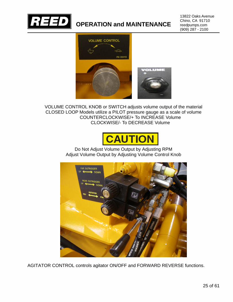
Another common auxiliary circuit function is hydraulic outriggers. When hydraulic outriggers are used, a larger directional valve is used to accommodate the two extra functions, the near and far side outriggers. These functions work similar to the agitator described above but are electrically operated by solenoids. The solenoids are controlled by operating the up/down switch found in the outrigger switch box located on either side of the machine. Although the machine may be hydraulically lifted and lowered, the outrigger legs must always be pinned in position as with manual outriggers for added security and stabilization.
OPERATION and MAINTENANCE
23 of 61
13822 Oaks Avenue Chino, CA 91710 reedpumps.com (909) 287 - 2100
CONTROLS
1. SYSTEM POWER energizes the system enabling Engine Start Button.
2. ENGINE START starts the engine when the System Power Switch is ON.
3. CHECK ENGINE LIGHT (if equipped) is on when engine experiencing possible problems.
4. STOP ENGINE LIGHT (if equipped) indicates operator to stop engine immediately.
5. CONTROL ON LIGHT indicates control circuit energized.
6. DIGITAL DISPLAY (if equipped) displays engine RPM, oil pressure, volts, temperature, coolant level, strokes per minute, and status of systems.
7. HOUR METER records the number of hours the electrical system has been activated when the ignition key is ON.
8. HOPPER GRATE SAFETY SWITCH engages EMERGERGENCY STOP when grate is lifted
9. LOCAL or REMOTE controls intended operation of machine.
10. EMERGENCY STOP stops all hydraulic functions of the concrete pump when pushed in.
Pull the Emergency Stop Button out to enable system to reset; Horn/Reset must be pressed to reset pump operation.
11. HORN/RESET activates system for operation
12. RPM +/- controls increase and decrease of engine RPM.
13. PUMP ON controls concrete pump ON/OFF function.
14. PUMP FORWARD REVERSE controls pump direction.
15. PUMP ON and PUMP REVERSE lights indicate pump status.
16. STROKE CHANGE changes stroke direction and eliminates proximity sensor signal while activated.
17. FAST CHANGE (if equipped) controls fast change feature for smoother operation under certain
conditions. Used only on closed loop models.
18. VIBRATOR (if equipped-HOPPER OPTION) controls vibrator activation
19. VOLUME CONTROL (if equipped) controls volume output of the concrete pump.
20. DIAGNOSTIC INTERFACE (if equipped is accessible by REED and authorized REED dealers only) is a computer port for system settings and diagnostic testing.
OPERATION and MAINTENANCE
24 of 61
13822 Oaks Avenue Chino, CA 91710 reedpumps.com (909) 287 - 2100
ERROR CODES EC01 – No radio link (no signal from either radio or cable) EC02 – J1939 CAN link error EC03 – RPM Plus EC04 – RPM Minus EC05 – Volume Plus EC06 – Volume Minus EC07 – Horn EC08 – Vibrator EC09 – Safety Valve 1 EC10 – Safety Valve 2 EC11 – Pump Coil A EC12 – Pump Coil B EC13 – S Tube A EC14 – S Tube B EC15 – Reverse Coil Output – enabled when calibration checkbox for Reverse Logic Change is unchecked. EC16 – Fast Change – enabled when the calibration checkbox for Fast Change is checked. EC17 – Reverse Light Out Error EC18 – Pump Light Out Error EC19 – Check Engine Light EC20 – Stop Engine Light EC21 – Volume PWM Output Error EC22 – Prox A&B Error EC23 – Wrong ID EC24 – Engine RPM Overspeed EC25 – Oil Low Pressure EC26 – Coolant Over Temp. EC27 – Low Battery Voltage EC28 – High Battery Voltage EC29 – Denison Fast Change EC30 – Denison A (only on C series with Denison Hydraulic pumps) EC31 – Denison B (only on C series with Denison Hydraulic pumps)
OPERATION and MAINTENANCE
25 of 61
13822 Oaks Avenue Chino, CA 91710 reedpumps.com (909) 287 - 2100
VOLUME CONTROL KNOB or SWITCH adjusts volume output of the material CLOSED LOOP Models utilize a PILOT pressure gauge as a scale of volume
COUNTERCLOCKWISE/+ To INCREASE Volume CLOCKWISE/- To DECREASE Volume
Do Not Adjust Volume Output by Adjusting RPM
Adjust Volume Output by Adjusting Volume Control Knob
AGITATOR CONTROL controls agitator ON/OFF and FORWARD REVERSE functions.
OPERATION and MAINTENANCE
26 of 61
13822 Oaks Avenue Chino, CA 91710 reedpumps.com (909) 287 - 2100
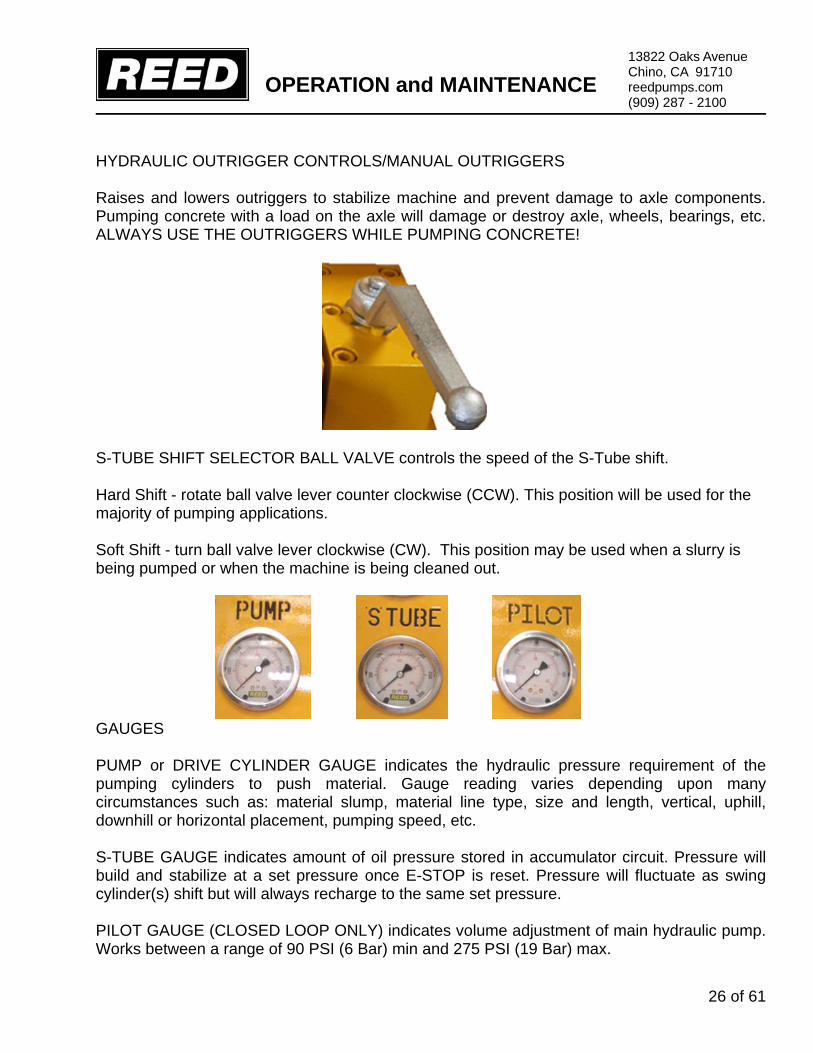
HYDRAULIC OUTRIGGER CONTROLS/MANUAL OUTRIGGERS Raises and lowers outriggers to stabilize machine and prevent damage to axle components. Pumping concrete with a load on the axle will damage or destroy axle, wheels, bearings, etc. ALWAYS USE THE OUTRIGGERS WHILE PUMPING CONCRETE!
S-TUBE SHIFT SELECTOR BALL VALVE controls the speed of the S-Tube shift.
Hard Shift - rotate ball valve lever counter clockwise (CCW). This position will be used for the majority of pumping applications.
Soft Shift - turn ball valve lever clockwise (CW). This position may be used when a slurry is being pumped or when the machine is being cleaned out.
GAUGES PUMP or DRIVE CYLINDER GAUGE indicates the hydraulic pressure requirement of the pumping cylinders to push material. Gauge reading varies depending upon many circumstances such as: material slump, material line type, size and length, vertical, uphill, downhill or horizontal placement, pumping speed, etc. S-TUBE GAUGE indicates amount of oil pressure stored in accumulator circuit. Pressure will build and stabilize at a set pressure once E-STOP is reset. Pressure will fluctuate as swing cylinder(s) shift but will always recharge to the same set pressure. PILOT GAUGE (CLOSED LOOP ONLY) indicates volume adjustment of main hydraulic pump. Works between a range of 90 PSI (6 Bar) min and 275 PSI (19 Bar) max.
OPERATION and MAINTENANCE
27 of 61
13822 Oaks Avenue Chino, CA 91710 reedpumps.com (909) 287 - 2100
CABLE REMOTE (RADIO REMOTE OPTIONAL, CONTACT REED FOR INFORMATION)
1. POWER ON/EMERGENCY STOP switch stops all functions of the concrete pump in OFF position. Move the Emergency Stop switch to ON to enable system reset; Horn/Reset must be pressed to reset pump operation.
2. CONTROL ON indicates control circuit energized.
3. HORN/RESET activates system for operation.
4. RPM +/- controls increase and decrease of engine RPM. 5. PUMP ON/OFF controls concrete pump ON/OFF function. 6. PUMP FORWARD/REVERSE controls pump direction.
7. VOLUME CONTROL (if equipped) controls volume output of the concrete pump.
8. STROKE CHANGE changes stroke direction and eliminates proximity sensor signal
while activated.
9. FAST CHANGE (if equipped-closed loop only) controls the fast change feature for smoother operation under certain conditions
OPERATION and MAINTENANCE
28 of 61
13822 Oaks Avenue Chino, CA 91710 reedpumps.com (909) 287 - 2100
TOWING Refer to the Safety Manual for towing safety precautions not limited to the following guidelines:
Ensure Unit Is Securely Attached Before Driving
Refer To Tow Hitch Instruction Manual
Tow Slowly and Safely Depending On Road Conditions
Overturning May Occur At Unsafe Speeds
NEVER Exceed 55 MPH
Maintain a Sufficient Distance for Braking
Overturning May Occur At Unsafe Stopping Distances
Do Not Tow With Concrete in the Hopper
Frequently Check, Monitor and Maintain all Towing Equipment
On Both the Towing Vehicle and the Trailer
Hitch Height
Adjust the Hitch Height to Allow for Safe Towing The Tongue Weight on Tandem Axle Trailers Increases as the Tongue is Raised
Towing with Insufficient or Excessive Tongue Weight is Dangerous Perform Road Tests to Ensure the Safety of the Tongue Weight
OPERATION and MAINTENANCE
29 of 61
13822 Oaks Avenue Chino, CA 91710 reedpumps.com (909) 287 - 2100
JOBSITE SET-UP
Refer to the Safety Manual for set-up safety precautions not limited to the following guidelines:
Ensure Machine Can Be Safely Operated In Set-Up Location
Away From Hazards and Dangers Away From Slopes and Excavations
Position Machine On As Solid and Level Ground As Possible
Place Outrigger Pads Below Outrigger Jacks If Necessary
Secure Jack Positions with Outrigger Pins and Locks
Not Using Outriggers Voids Warranty
Damage Will Occur If Outriggers Are Not Used
OPERATION and MAINTENANCE
30 of 61
13822 Oaks Avenue Chino, CA 91710 reedpumps.com (909) 287 - 2100
PRIMING Priming consists of pumping a lubricant to coat the s-tube and delivery lines to assist the initial concrete material in getting through the delivery lines and avoid blockages. Once the delivery lines are full of concrete, that material will supply the lubrication necessary for the material to flow through the delivery lines. However, it is imperative that a primer be used ahead of the initial concrete material to pre-lubricate the lines in order to avoid blockages. A suggested grout to use for priming and lubrication may consist of 2 parts sand and 1 part cement and mixed to a consistency of a thick cream. The amount of grout required depends on the length of the delivery line as well as the material being pumped. Operator experience will eventually indicate the amount to be required. In addition to grout, there is a wide variety of priming products available on the market.
OPERATION and MAINTENANCE
31 of 61
13822 Oaks Avenue Chino, CA 91710 reedpumps.com (909) 287 - 2100
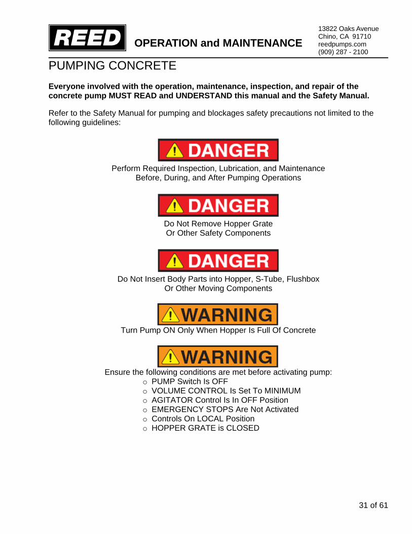
PUMPING CONCRETE Everyone involved with the operation, maintenance, inspection, and repair of the concrete pump MUST READ and UNDERSTAND this manual and the Safety Manual. Refer to the Safety Manual for pumping and blockages safety precautions not limited to the following guidelines:
Perform Required Inspection, Lubrication, and Maintenance
Before, During, and After Pumping Operations
Do Not Remove Hopper Grate Or Other Safety Components
Do Not Insert Body Parts into Hopper, S-Tube, Flushbox
Or Other Moving Components
Turn Pump ON Only When Hopper Is Full Of Concrete
Ensure the following conditions are met before activating pump:
o PUMP Switch Is OFF o VOLUME CONTROL Is Set To MINIMUM o AGITATOR Control Is In OFF Position o EMERGENCY STOPS Are Not Activated o Controls On LOCAL Position o HOPPER GRATE is CLOSED
OPERATION and MAINTENANCE
32 of 61
13822 Oaks Avenue Chino, CA 91710 reedpumps.com (909) 287 - 2100
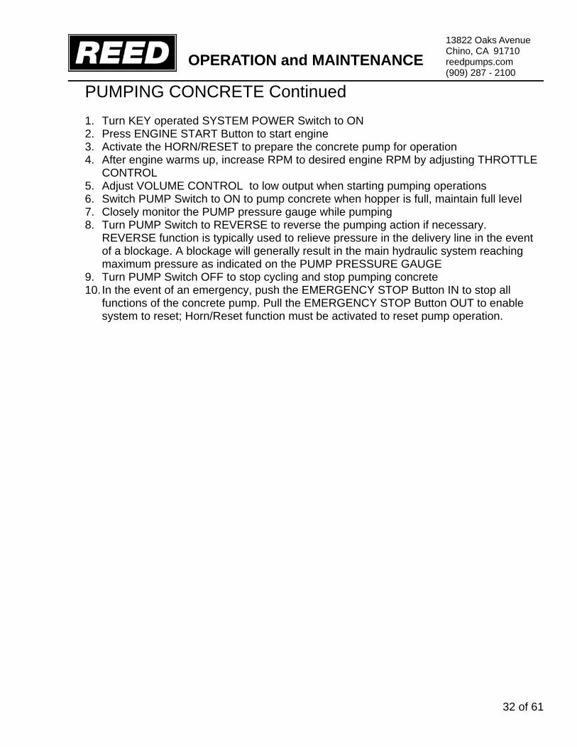
PUMPING CONCRETE Continued 1. Turn KEY operated SYSTEM POWER Switch to ON 2. Press ENGINE START Button to start engine 3. Activate the HORN/RESET to prepare the concrete pump for operation 4. After engine warms up, increase RPM to desired engine RPM by adjusting THROTTLE
CONTROL 5. Adjust VOLUME CONTROL to low output when starting pumping operations 6. Switch PUMP Switch to ON to pump concrete when hopper is full, maintain full level 7. Closely monitor the PUMP pressure gauge while pumping 8. Turn PUMP Switch to REVERSE to reverse the pumping action if necessary.
REVERSE function is typically used to relieve pressure in the delivery line in the event of a blockage. A blockage will generally result in the main hydraulic system reaching maximum pressure as indicated on the PUMP PRESSURE GAUGE
9. Turn PUMP Switch OFF to stop cycling and stop pumping concrete 10. In the event of an emergency, push the EMERGENCY STOP Button IN to stop all
functions of the concrete pump. Pull the EMERGENCY STOP Button OUT to enable system to reset; Horn/Reset function must be activated to reset pump operation.
OPERATION and MAINTENANCE
33 of 61
13822 Oaks Avenue Chino, CA 91710 reedpumps.com (909) 287 - 2100
JOBSITE CLEANUP
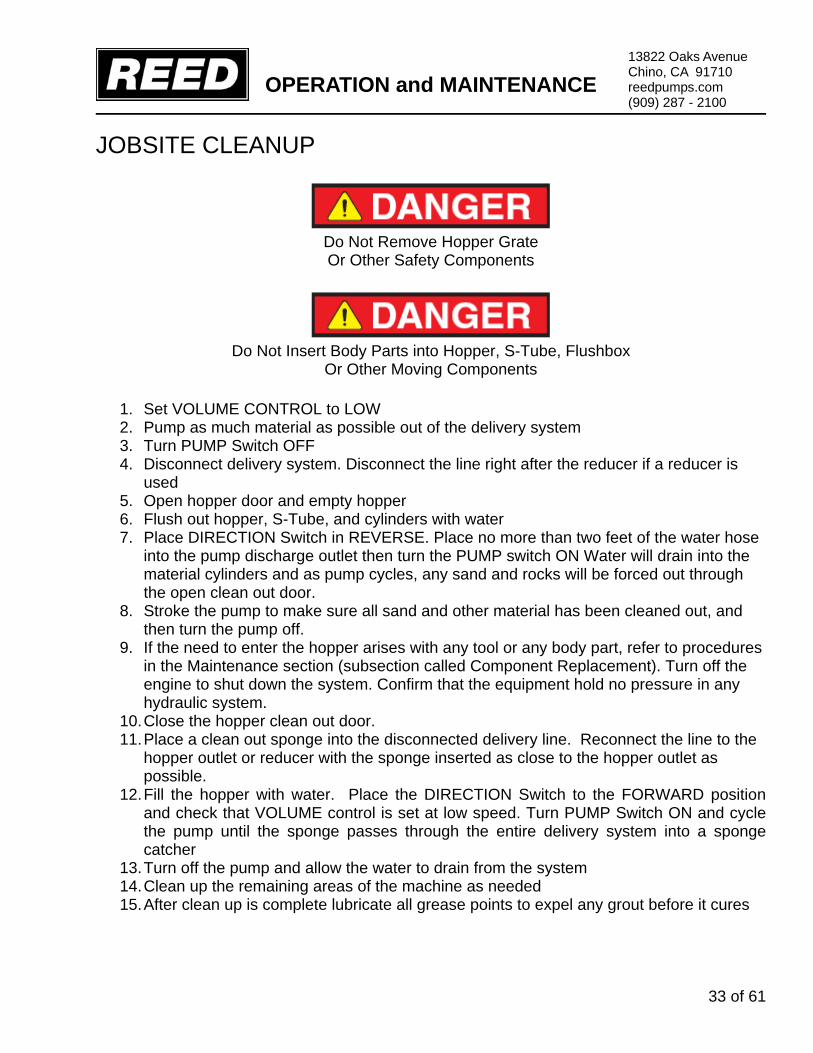
Do Not Remove Hopper Grate Or Other Safety Components
Do Not Insert Body Parts into Hopper, S-Tube, Flushbox
Or Other Moving Components
1. Set VOLUME CONTROL to LOW 2. Pump as much material as possible out of the delivery system 3. Turn PUMP Switch OFF 4. Disconnect delivery system. Disconnect the line right after the reducer if a reducer is
used 5. Open hopper door and empty hopper 6. Flush out hopper, S-Tube, and cylinders with water 7. Place DIRECTION Switch in REVERSE. Place no more than two feet of the water hose
into the pump discharge outlet then turn the PUMP switch ON Water will drain into the material cylinders and as pump cycles, any sand and rocks will be forced out through the open clean out door.
8. Stroke the pump to make sure all sand and other material has been cleaned out, and then turn the pump off.
9. If the need to enter the hopper arises with any tool or any body part, refer to procedures in the Maintenance section (subsection called Component Replacement). Turn off the engine to shut down the system. Confirm that the equipment hold no pressure in any hydraulic system.
10. Close the hopper clean out door. 11. Place a clean out sponge into the disconnected delivery line. Reconnect the line to the
hopper outlet or reducer with the sponge inserted as close to the hopper outlet as possible.
12. Fill the hopper with water. Place the DIRECTION Switch to the FORWARD position and check that VOLUME control is set at low speed. Turn PUMP Switch ON and cycle the pump until the sponge passes through the entire delivery system into a sponge catcher
13. Turn off the pump and allow the water to drain from the system 14. Clean up the remaining areas of the machine as needed 15. After clean up is complete lubricate all grease points to expel any grout before it cures
OPERATION and MAINTENANCE
34 of 61
13822 Oaks Avenue Chino, CA 91710 reedpumps.com (909) 287 - 2100
MAINTENANCE
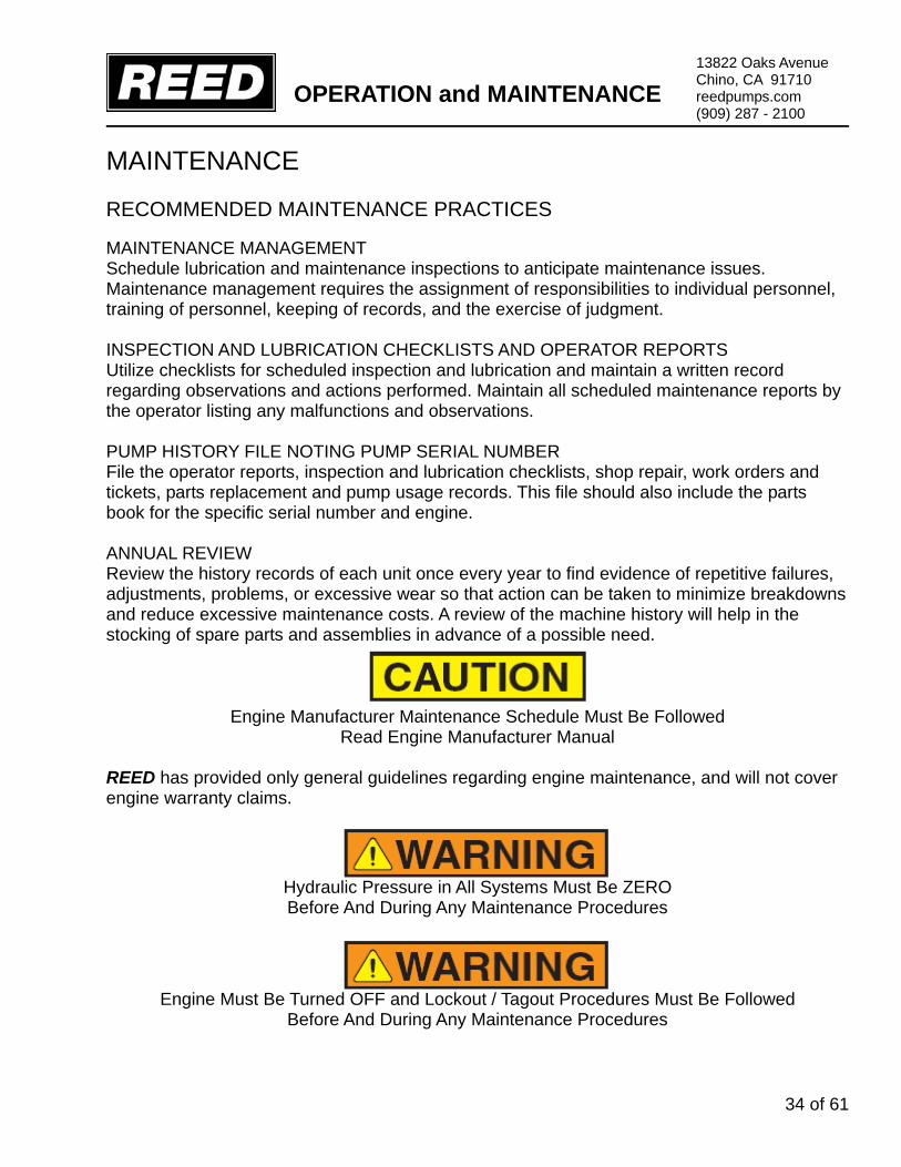
RECOMMENDED MAINTENANCE PRACTICES MAINTENANCE MANAGEMENT Schedule lubrication and maintenance inspections to anticipate maintenance issues. Maintenance management requires the assignment of responsibilities to individual personnel, training of personnel, keeping of records, and the exercise of judgment. INSPECTION AND LUBRICATION CHECKLISTS AND OPERATOR REPORTS Utilize checklists for scheduled inspection and lubrication and maintain a written record regarding observations and actions performed. Maintain all scheduled maintenance reports by the operator listing any malfunctions and observations. PUMP HISTORY FILE NOTING PUMP SERIAL NUMBER File the operator reports, inspection and lubrication checklists, shop repair, work orders and tickets, parts replacement and pump usage records. This file should also include the parts book for the specific serial number and engine. ANNUAL REVIEW Review the history records of each unit once every year to find evidence of repetitive failures, adjustments, problems, or excessive wear so that action can be taken to minimize breakdowns and reduce excessive maintenance costs. A review of the machine history will help in the stocking of spare parts and assemblies in advance of a possible need.
Engine Manufacturer Maintenance Schedule Must Be Followed
Read Engine Manufacturer Manual
REED has provided only general guidelines regarding engine maintenance, and will not cover engine warranty claims.
Hydraulic Pressure in All Systems Must Be ZERO Before And During Any Maintenance Procedures
Engine Must Be Turned OFF and Lockout / Tagout Procedures Must Be Followed
Before And During Any Maintenance Procedures
OPERATION and MAINTENANCE
35 of 61
13822 Oaks Avenue Chino, CA 91710 reedpumps.com (909) 287 - 2100
GENERAL MAINTENANCE AREAS
Perform scheduled inspections to identify and detect any potential problems. The list presented should be inspected and checked on a regular basis and is a recommended minimum. TRAILER
Frame integrity, visually check welds, cracks Torsion axle secure Wheels and tires, lug nuts tight, tire pressure, bearings oiled/greased and adjusted, dust
caps on and secure Electric brakes, breakaway switch connected Front jack stand handle turns easily, smoothly Manual jacks slide freely, lock pins in place Lighting and Wiring in good condition, operational
ENGINE (refer to engine manufacturer manual)
Inspect mounts, bolts, brackets and belts Oil and coolant fluids at proper level, check for leaks Fuel system, tank mounting, filter condition, leaks, damaged lines Battery hold down, condition, tightness of cables Key switch, indicator lights Throttle control functional Air cleaner and muffler securely mounted
PUMP CELL
Visually check for structural damage, cracked welds Hydraulic drive cylinders in good condition, secure, check for leaks Material cylinders secure, tie rods tight Water box structurally sound, clean, cover in place S-Tube shift mechanism structurally sound, all pins and retainers in place Hydraulic shift cylinder(s) in good condition Bearing housing, seals etc. in good condition Hydraulic hoses secure no leaks
HOPPER ASSEMBLY
Visually check for structural damage, cracked welds S-Tube secure, in good condition Check condition of wear plate, wear ring, seals Check connection of s-tube to outlet, seals, bearing Hopper Grate, Hinges and Bushings in good condition E-STOP Hopper Grate Sensor is operational and in good condition Hopper drain is functional Hopper is clean Zerk fittings accept grease
OPERATION and MAINTENANCE
36 of 61
13822 Oaks Avenue Chino, CA 91710 reedpumps.com (909) 287 - 2100
MAIN CONTROLS Control box in good condition, sealed, not damaged All toggles in good condition, stay in position or momentarily return to center Control identification in good condition, legible Gauges in good condition
REMOTE CONTROLS
Control console in good condition, not damaged Switch in good condition Cord in good condition, no cuts, securely mounted to box
HYDRAULIC SYSTEM
Hydraulic tank securely mounted, covers tight Breather, filler cap and strainer in place, level sight gauge in proper condition Check filter condition indicators Hydraulic oil cooler securely mounted, connections tight Check accumulator condition, mounting brackets & clamps Hydraulic fluid to proper level and clean All hoses and tubing secure, check for leaks
OPERATION and MAINTENANCE
37 of 61
13822 Oaks Avenue Chino, CA 91710 reedpumps.com (909) 287 - 2100
LUBRICATION The REED concrete pump is equipped with several components that require frequent lubrication. These areas involve the s-tube shifting mechanism, swing components, the shift and outlet bearings and agitator. to insure the economical service and the long life of these components, grease fittings are installed at each point.
Rapid wear and possible shutdown will result if the unit is operated with inadequate lubrication. Follow the recommendations stated herein, and if needed increase the application of lubricants above these recommendations when the equipment is subject to heavy usage.
RECOMMENDED LUBRICATING INTERVALS Recommended lubrication intervals are based on normal use under normal conditions. The lubrication interval must be increased to meet more challenging uses and uses which subject the equipment to high and/or unusual concentration of forces. The lubrication interval must be increased if the pump has been exposed to environmental conditions such as low humidity, high humidity, excessive dust, high temperatures, low temperatures, heavy rainfall, long term storage, ocean air, etc… 1) every hour of operation 2) after completion of every job All lubrication points must be greased on each and every interval as recommended. TYPE OF LUBRICANT
Use EP grease, extreme pressure grease available for wheel bearings, general purpose grease, Shell Alvania EP (LFH2), or equivalent if this lubricant is unavailable in your area
Do NOT use Moly grease, grease with Moly additives
LUBRICATION POINTS The following graphics are for REFERENCE ONLY.
OPERATION and MAINTENANCE
38 of 61
13822 Oaks Avenue Chino, CA 91710 reedpumps.com (909) 287 - 2100
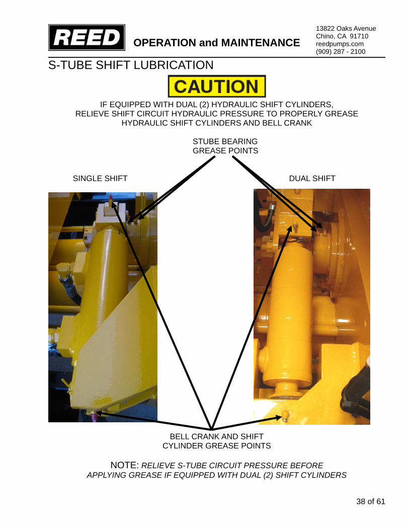
S-TUBE SHIFT LUBRICATION
IF EQUIPPED WITH DUAL (2) HYDRAULIC SHIFT CYLINDERS,
RELIEVE SHIFT CIRCUIT HYDRAULIC PRESSURE TO PROPERLY GREASE HYDRAULIC SHIFT CYLINDERS AND BELL CRANK
STUBE BEARING GREASE POINTS SINGLE SHIFT DUAL SHIFT
BELL CRANK AND SHIFT CYLINDER GREASE POINTS
NOTE: RELIEVE S-TUBE CIRCUIT PRESSURE BEFORE
APPLYING GREASE IF EQUIPPED WITH DUAL (2) SHIFT CYLINDERS
OPERATION and MAINTENANCE
39 of 61
13822 Oaks Avenue Chino, CA 91710 reedpumps.com (909) 287 - 2100
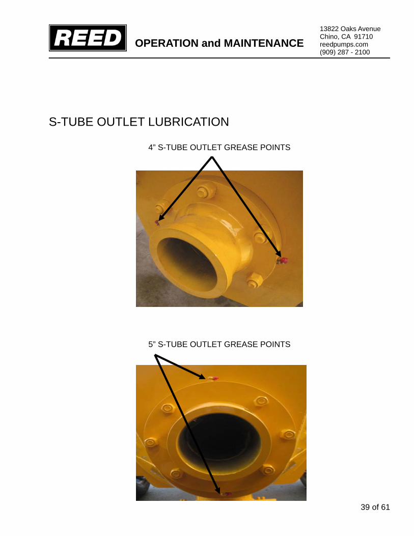
S-TUBE OUTLET LUBRICATION
4” S-TUBE OUTLET GREASE POINTS
5” S-TUBE OUTLET GREASE POINTS
OPERATION and MAINTENANCE
40 of 61
13822 Oaks Avenue Chino, CA 91710 reedpumps.com (909) 287 - 2100
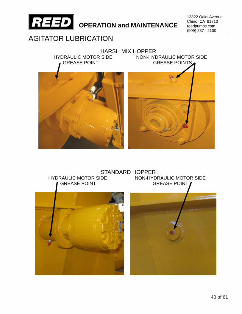
AGITATOR LUBRICATION
HARSH MIX HOPPER HYDRAULIC MOTOR SIDE NON-HYDRAULIC MOTOR SIDE GREASE POINT GREASE POINTS
STANDARD HOPPER
HYDRAULIC MOTOR SIDE NON-HYDRAULIC MOTOR SIDE GREASE POINT GREASE POINT
OPERATION and MAINTENANCE
41 of 61
13822 Oaks Avenue Chino, CA 91710 reedpumps.com (909) 287 - 2100
HYDRAULIC SYSTEM Hydraulic pumps are used to supply the flow of oil necessary to operate actuators of the concrete pump.
Contamination of the Oil Is the Leading Contributor to System Malfunctions
Extreme care must be exercised to prevent contaminants from entering the system. Always cap or plug open ports and hydraulic lines. HYDRAULIC TANK Hydraulic tank can be equipped with an access cover with breather. A sight and temperature gauge is installed on the tank to determine the fluid level and temperature inside the tank. The tank is also equipped with drain valve. To accomplish filtration, hydraulic tanks can be equipped with the following: internal magnetic suction strainers, a suction filter, a return filter and a pressure filter. NOTE: Not all models use all of these components. Suction and return filters are equipped with an indicator gauge to monitor filter restriction. An oil cooler is adjacent to the engine cooling unit.
OPERATION and MAINTENANCE
42 of 61
13822 Oaks Avenue Chino, CA 91710 reedpumps.com (909) 287 - 2100
HYDRAULIC SYSTEM MAINTENANCE ITEM DESCRIPTIONS FLUID Check fluid level and oil clarity daily with sight gauge provided. Maintain level at full mark. Add hydraulic oil through the return filter fill port when necessary. TANK BREATHER Clean every 50 hours of operation. Remove from tank, clean with solvent and air blow dry. FILTER Change after first 50 hours of operation. Thereafter change every 250 hours of operation or when condition gauge indicates change is necessary. HYDRAULIC TANK Change oil in tank every 500 hours of operation or yearly, whichever comes first. HYDRAULIC FLUID The hydraulic system is filled with Shell Oil Company TELLUS #46. It is to be used in ambient temperatures of 39-90 F (4-32 C). The normal fluid temperature will range from 100-167 F (38-75 C). For ambient temperatures of 90 F (32 C) and above, use fluid designated with an ISO rating of 68. Use ISO 32 for ambient temperatures of 32 F (4 C) and below.
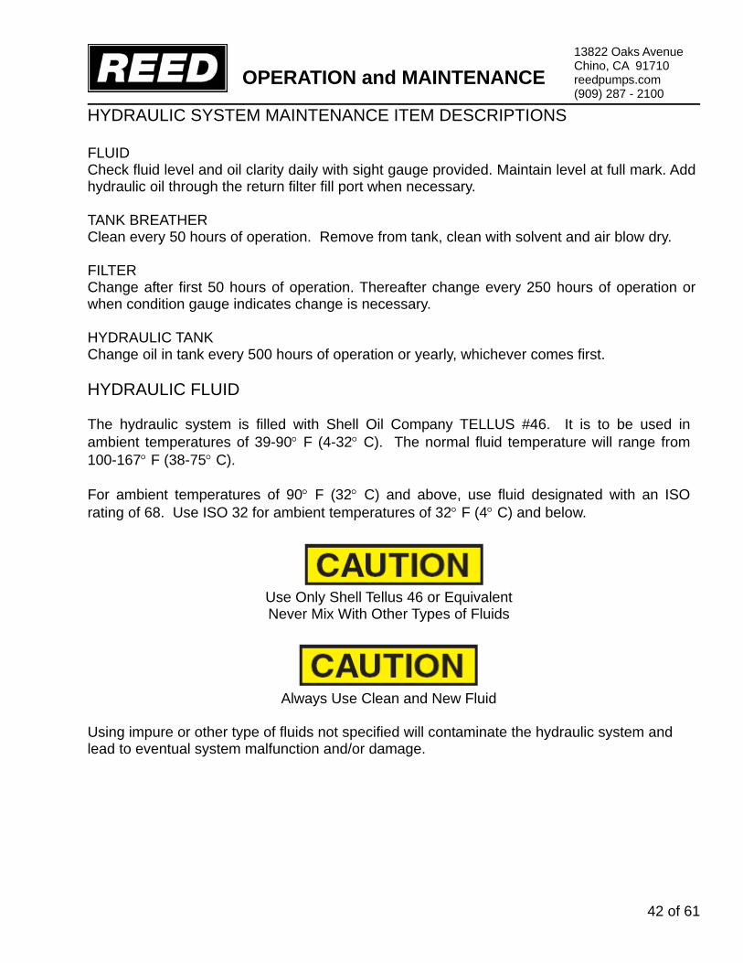
Use Only Shell Tellus 46 or Equivalent Never Mix With Other Types of Fluids
Always Use Clean and New Fluid
Using impure or other type of fluids not specified will contaminate the hydraulic system and lead to eventual system malfunction and/or damage.
OPERATION and MAINTENANCE
43 of 61
13822 Oaks Avenue Chino, CA 91710 reedpumps.com (909) 287 - 2100
ADDING HYDRAULIC FLUID There are a few common methods for filling the hydraulic tank as described below. Exercise extreme care when adding fluid to the hydraulic tank to avoid contamination. To prevent any dirt or water from entering the hydraulic tank, thoroughly clean area around the return filter fill port plug, the vented fill cap or the inspection cover. Remove return filter fill port plug, vented cap or inspection cover. Fill system to MAX LEVEL mark on sight gauge with new clean hydraulic fluid. If a pump is used to transfer the fluid, ensure the pump filter is clean. If pouring fluid from a container, pour it through a fine wire mesh screen, 200 mesh or finer. Replace filter fill port plug, vented cap or inspection cover immediately after filling tank to proper level.
Do Not Use Cloth for Straining Fluid
Lint Is a Contaminant Harmful To the Hydraulic System FILTER SERVICING
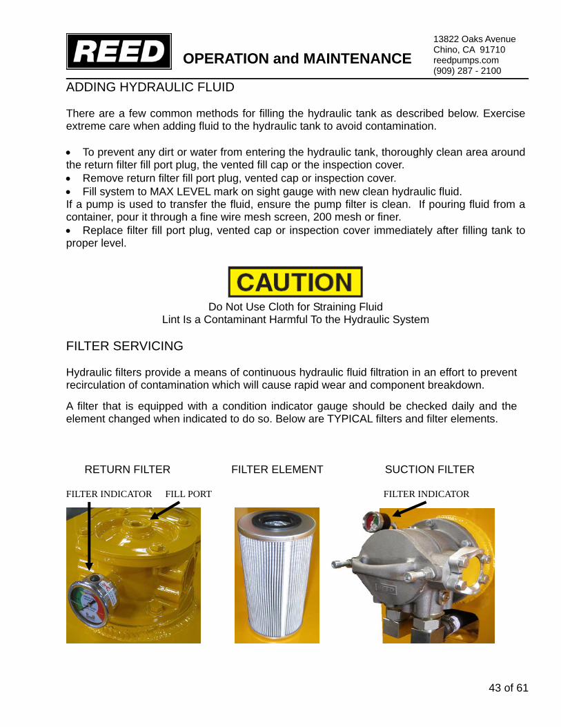
Hydraulic filters provide a means of continuous hydraulic fluid filtration in an effort to prevent recirculation of contamination which will cause rapid wear and component breakdown.
A filter that is equipped with a condition indicator gauge should be checked daily and the element changed when indicated to do so. Below are TYPICAL filters and filter elements. RETURN FILTER FILTER ELEMENT SUCTION FILTER FILTER INDICATOR FILL PORT FILTER INDICATOR
OPERATION and MAINTENANCE
44 of 61
13822 Oaks Avenue Chino, CA 91710 reedpumps.com (909) 287 - 2100
To change the filter elements:
1. Shut off machine. 2. VERIFY PRESSURES IN ALL CIRCUITS READ ZERO! 3. Wipe clean any dirt and grime from area surrounding filter housing 4. Loosen the filter cover plate bolts 5. Carefully remove cover so as not to damage the gasket or O-ring 6. Remove and element bypass valve (if equipped) 7. Discard only element and discard responsibly 8. Install bypass valve (if equipped) and new element and replace cover 9. Wipe clean any contaminants around high pressure filter 10. Remove filter housing then remove and discard filter element 11. Check and replace o-ring or gasket if necessary 12. Replace filter element and install filter housing 13. Start up machine and observe for leakage
Do Not Wash Out and Reuse Disposable Filter Elements
CLEANING THE HYDRAULIC TANK The hydraulic tank should be drained and cleaned after 500 hours of operation or yearly, whichever occurs first, to assist in keeping the systems clean and in proper condition.
1. Shut off machine 2. VERIFY PRESSURES IN ALL CIRCUITS READ ZERO! 3. Place a suitable size container under the hydraulic tank drain fitting and then remove
drain plug. Dispose of used oil responsibly 4. After draining, remove the access cover on the hydraulic tank being careful not to
damage the gasket 5. Remove, disassemble and clean magnetic suction strainers before reassembly (if
equipped) 6. Flush the inside of hydraulic tank with clean solvent and wipe clean with lint free cloths 7. Install suction strainers (if equipped) 8. Replace sight gauge 9. Install the tank drain plug and access cover with gasket. 10. Change the hydraulic system filter element(s) and breather cap 11. Refill the hydraulic tank with new clean hydraulic fluid to MAX LEVEL mark 12. Start machine and check for leaks
OPERATION and MAINTENANCE
45 of 61
13822 Oaks Avenue Chino, CA 91710 reedpumps.com (909) 287 - 2100
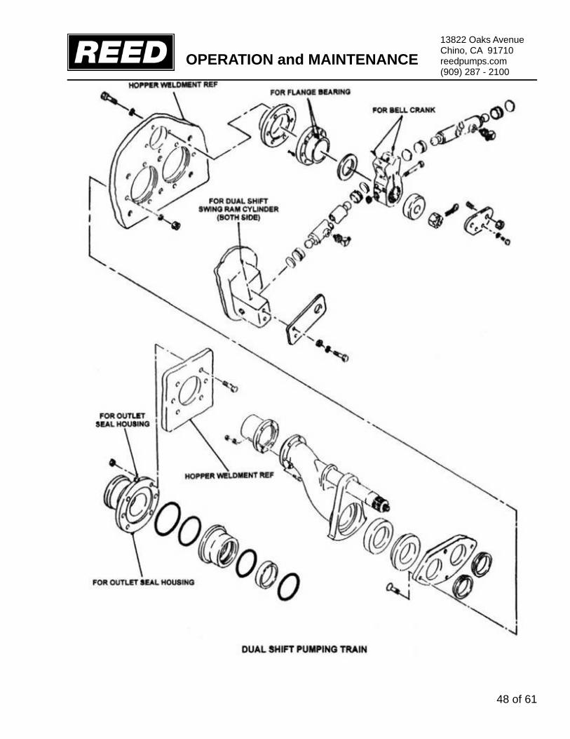
COMPONENT REPLACEMENT When parts are worn, do not delay in replacement. Continued usage with worn parts may lead to damage of other components. This section is provided as a general guideline to assist in replacing major components that will wear. Please contact the REED Service Department or your local dealer for technical support. S-TUBE, WEAR RING, AND WEAR PLATE
The sealing characteristics of the s-tube depend on the positive contact of the wear ring, located inside the s-tube, to the wear plate mounted inside of the hopper. the abrasiveness and friction of the concrete will cause wear and a breakdown of the sealing action. As this breakdown occurs, periodic adjustments to the s-tube can be made. This will help to improve the sealing quality; however, eventually the components will need to be replaced. Adjustment or parts are required if: s-tube concrete build up deep grooves have developed on the face of the wear plate and/or on the wear ring When the output volume at the end of the delivery line noticeably begins to decrease or
eventually stops When the material being pumped is being forced back into the hopper under pressure
Pressures in All Hydraulic Circuits Must Be ZERO
BEFORE AND DURING Any Maintenance Procedures
Engine Must Be Turned OFF and Lockout / Tagout Procedures Must Be Followed
BEFORE AND DURING Any Maintenance Procedures NOTE: The following graphics are for REFERENCE ONLY.
OPERATION and MAINTENANCE
46 of 61
13822 Oaks Avenue Chino, CA 91710 reedpumps.com (909) 287 - 2100
OPERATION and MAINTENANCE
47 of 61
13822 Oaks Avenue Chino, CA 91710 reedpumps.com (909) 287 - 2100
OPERATION and MAINTENANCE
48 of 61
13822 Oaks Avenue Chino, CA 91710 reedpumps.com (909) 287 - 2100
OPERATION and MAINTENANCE
49 of 61
13822 Oaks Avenue Chino, CA 91710 reedpumps.com (909) 287 - 2100
Pressures in ALL Hydraulic Circuits Must Be ZERO
BEFORE AND DURING Any Maintenance Procedures
Engine Must Be Turned OFF and Lockout / Tagout Procedures Must Be Followed
BEFORE AND DURING Any Maintenance Procedures
1. Shut off machine 2. VERIFY PRESSURES IN ALL CIRCUITS READ ZERO! 3. Loosen bell crank pinch bolt (s), remove cotter pin, loosen s-tube nut 1 turn 4. Remove outlet bolts, remove outlet 5. Remove outlet seal housing followed by s-tube nut, spacer, bell crank, washer, swing
ram(s) 6. Place a sling from an overhead hoist around the discharge end of s-tube to help
support the tube. 7. Pry s-tube toward outlet, remove wear ring & thrust seal. The s-tube may be swung
upside down to provide access to clean. Thrust seal groove or cavity must be properly cleaned
Note: for better access, the s-tube may be removed from hopper by removing flange bearing, seal and chromed outlet and hoisting it out of hopper 8. If wear plate is to be changed, remove wear plate mounting bolts. Pry wear plate from
hopper using provided jack bolt. 9. Pry anti-chip rings out of hopper bore. Use caution not to damage chrome concrete
cylinder. Clean anti-chip ring bore and wear plate area. Replace o-rings (if applicable). Test-fit new bolts in new wear plate-they should be below the surface of the wear plate and not protruding (grind if necessary).
10. Apply small bead of silicone to outer diameter of anti-chip rings, install into hopper bore with split at bottom
11. Apply small amount of silicone to hopper-side of wear plate and bolt-heads. Install wear plate, hand tighten bolts. A short pair of bolts with nuts may be placed underneath new wear plate to adjust and align to concrete cylinders. Torque wear plate mounting bolts to 250 ft lbs, remove adjusting bolts.
OPERATION and MAINTENANCE
50 of 61
13822 Oaks Avenue Chino, CA 91710 reedpumps.com (909) 287 - 2100
12. Install new thrust seal & wear ring in s-tube. 13. Install shaft seal and flange bearing (if removed), torque bolts to 100 ft lbs 14. Slide s-tube forward against wear plate, install washer, align/ mount bell crank, install
spacer and castle nut. Do not tighten yet. 15. Replace outlet seals in proper orientation, apply grease and install outlet seal housing.
Install outlet, torque outlet bolts to 100 ft lbs. Grease all zerk fittings for s-tube until grease comes out of seals.
16. Remove sling, tighten s-tube nut/bolt. It may be helpful to start machine and cycle s-tube to help new parts seat. Do final tightening to s-tube nut/bolt, install cotter pin/retainer, tighten bell crank pinch bolt (s). The nut should be as tight as possible without hampering the shift of s-tube
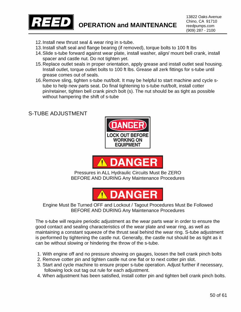
S-TUBE ADJUSTMENT
Pressures in ALL Hydraulic Circuits Must Be ZERO
BEFORE AND DURING Any Maintenance Procedures
Engine Must Be Turned OFF and Lockout / Tagout Procedures Must Be Followed
BEFORE AND DURING Any Maintenance Procedures
The s-tube will require periodic adjustment as the wear parts wear in order to ensure the good contact and sealing characteristics of the wear plate and wear ring, as well as maintaining a constant squeeze of the thrust seal behind the wear ring. S-tube adjustment is performed by tightening the castle nut. Generally, the castle nut should be as tight as it can be without slowing or hindering the throw of the s-tube. 1. With engine off and no pressure showing on gauges, loosen the bell crank pinch bolts 2. Remove cotter pin and tighten castle nut one flat or to next cotter pin slot. 3. Start and cycle machine to ensure proper s-tube operation. Adjust further if necessary,
following lock out tag out rule for each adjustment. 4. When adjustment has been satisfied, install cotter pin and tighten bell crank pinch bolts.
OPERATION and MAINTENANCE
51 of 61
13822 Oaks Avenue Chino, CA 91710 reedpumps.com (909) 287 - 2100
PISTON CUP AND GUIDE BAND REMOVAL/REPLACEMENT Because of the abrasiveness of the material being pumped, it will be necessary to periodically replace the piston cups. Signs and indicators of worn parts might be:
The slurry or abrasive material being pumped starts to appear in flush box Leading edge of piston cup is noticeably deteriorated or unevenly worn The water or lubricating oil in water box begins to rapidly lower level without any sign of
leakage Operation is rough and erratic
Pressures in ALL Hydraulic Circuits Must Be ZERO
BEFORE AND DURING Any Maintenance Procedures
Engine Must Be Turned OFF and Lockout / Tagout Procedures Must Be Followed
BEFORE AND DURING Any Maintenance Procedures
1. Drain all oil or water from the flush box. 2. Cycle machine using appropriate controls until one of the cylinders is completely
retracted. Turn off engine and allow hydraulic systems to completely depressurize. 3. As a precaution, mark location of proximity sensor adjusting bracket. Remove proximity
sensor cross bracket. 4. Mark the end of the piston coupler so that it can be placed in the same relation during
reassembly. 5. Unbolt and remove top and bottom halves of coupler. Pry the piston assembly into flush
box. 6. Disassemble and clean piston adapter and plate. Check flatness of plate, replace if
necessary. 7. Install and grease new guide band. Push adapter/guide band squarely into cleaned and
greased concrete cylinder. 8. Install coupler using medium strength Loctite on bolts and torque to 90 ft lbs. 9. Start and completely extend the adapter and guide band to hopper side. Run in Forward
or Reverse as necessary to expose fully extended piston adapter. 10. Turn off engine and allow all hydraulic systems to completely depressurize
OPERATION and MAINTENANCE
52 of 61
13822 Oaks Avenue Chino, CA 91710 reedpumps.com (909) 287 - 2100
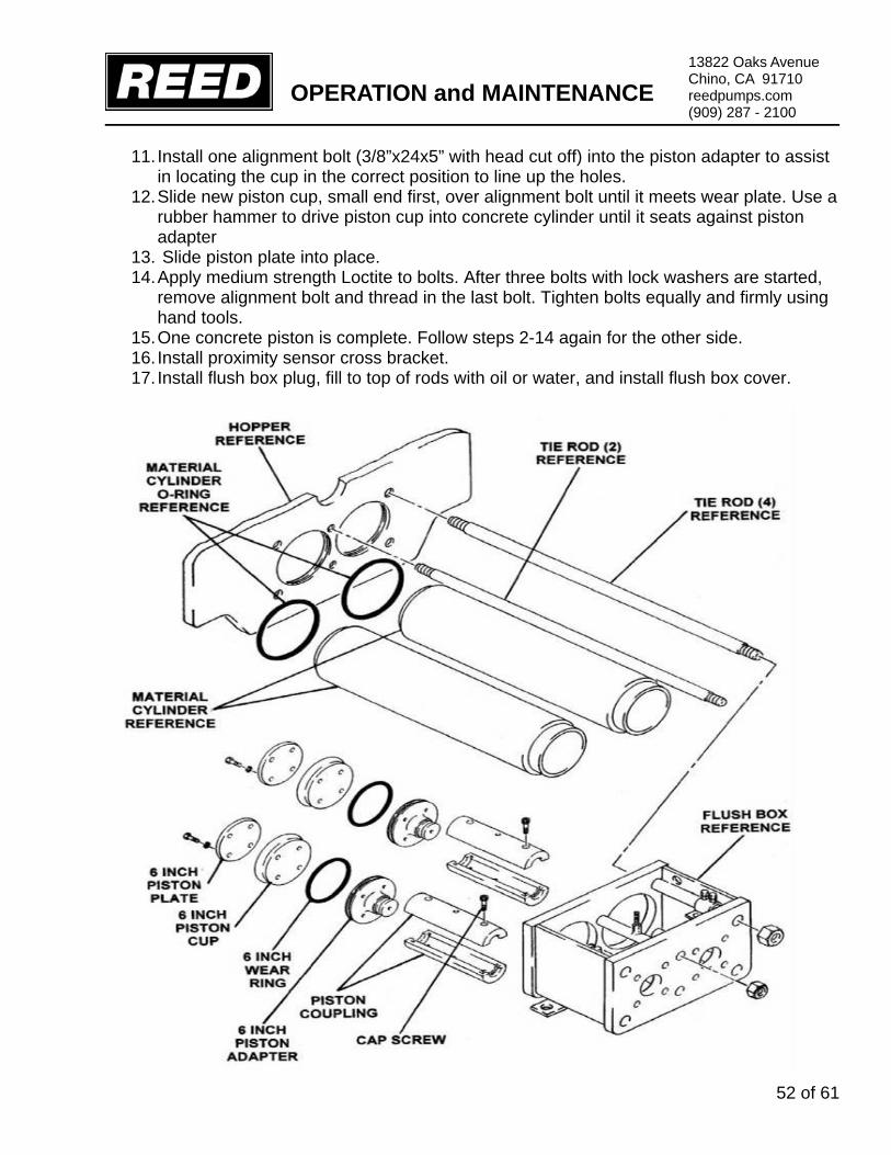
11. Install one alignment bolt (3/8”x24x5” with head cut off) into the piston adapter to assist
in locating the cup in the correct position to line up the holes. 12. Slide new piston cup, small end first, over alignment bolt until it meets wear plate. Use a
rubber hammer to drive piston cup into concrete cylinder until it seats against piston adapter
13. Slide piston plate into place. 14. Apply medium strength Loctite to bolts. After three bolts with lock washers are started,
remove alignment bolt and thread in the last bolt. Tighten bolts equally and firmly using hand tools.
15. One concrete piston is complete. Follow steps 2-14 again for the other side. 16. Install proximity sensor cross bracket. 17. Install flush box plug, fill to top of rods with oil or water, and install flush box cover.
OPERATION and MAINTENANCE
53 of 61
13822 Oaks Avenue Chino, CA 91710 reedpumps.com (909) 287 - 2100
ACCUMULATOR
Pressures in ALL Hydraulic Circuits Must Be ZERO
BEFORE AND DURING Any Maintenance Procedures
Engine Must Be Turned OFF and Lockout / Tagout Procedures Must Be Followed
BEFORE AND DURING Any Maintenance Procedures
The hydraulic accumulator is a pressurized vessel and only QUALIFIED TECHNICIANS should perform the necessary repairs. Always drain the fluid COMPLETELY from the accumulator before performing any work on the component. A qualified technician can check the pre-charge pressure of the accumulator using an accumulator charge kit if low pressure is suspected. Check the pre-charge pressure of the accumulator if the needle of the hydraulic s-tube gauge does not suddenly drop off at the specified pressure when the hydraulic s-tube circuit is depressurizing, or if the s-tube action is noticeably slow and weak.
OPERATION and MAINTENANCE
54 of 61
13822 Oaks Avenue Chino, CA 91710 reedpumps.com (909) 287 - 2100
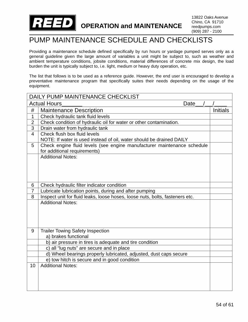
PUMP MAINTENANCE SCHEDULE AND CHECKLISTS Providing a maintenance schedule defined specifically by run hours or yardage pumped serves only as a general guideline given the large amount of variables a unit might be subject to, such as weather and ambient temperature conditions, jobsite conditions, material differences of concrete mix design, the load burden the unit is typically subject to, i.e. light, medium or heavy duty operation, etc. The list that follows is to be used as a reference guide. However, the end user is encouraged to develop a preventative maintenance program that specifically suites their needs depending on the usage of the equipment.
DAILY PUMP MAINTENANCE CHECKLIST Actual Hours Date / / # Maintenance Description Initials1 Check hydraulic tank fluid levels 2 Check condition of hydraulic oil for water or other contamination. 3 Drain water from hydraulic tank 4 Check flush box fluid levels
NOTE: If water is used instead of oil, water should be drained DAILY
5 Check engine fluid levels (see engine manufacturer maintenance schedule for additional requirements)
Additional Notes:
6 Check hydraulic filter indicator condition 7 Lubricate lubrication points, during and after pumping 8 Inspect unit for fluid leaks, loose hoses, loose nuts, bolts, fasteners etc. Additional Notes:
9 Trailer Towing Safety Inspection a) brakes functional
b) air pressure in tires is adequate and tire condition c) all “lug nuts” are secure and in place d) Wheel bearings properly lubricated, adjusted, dust caps secure e) tow hitch is secure and in good condition
10 Additional Notes:
OPERATION and MAINTENANCE
55 of 61
13822 Oaks Avenue Chino, CA 91710 reedpumps.com (909) 287 - 2100
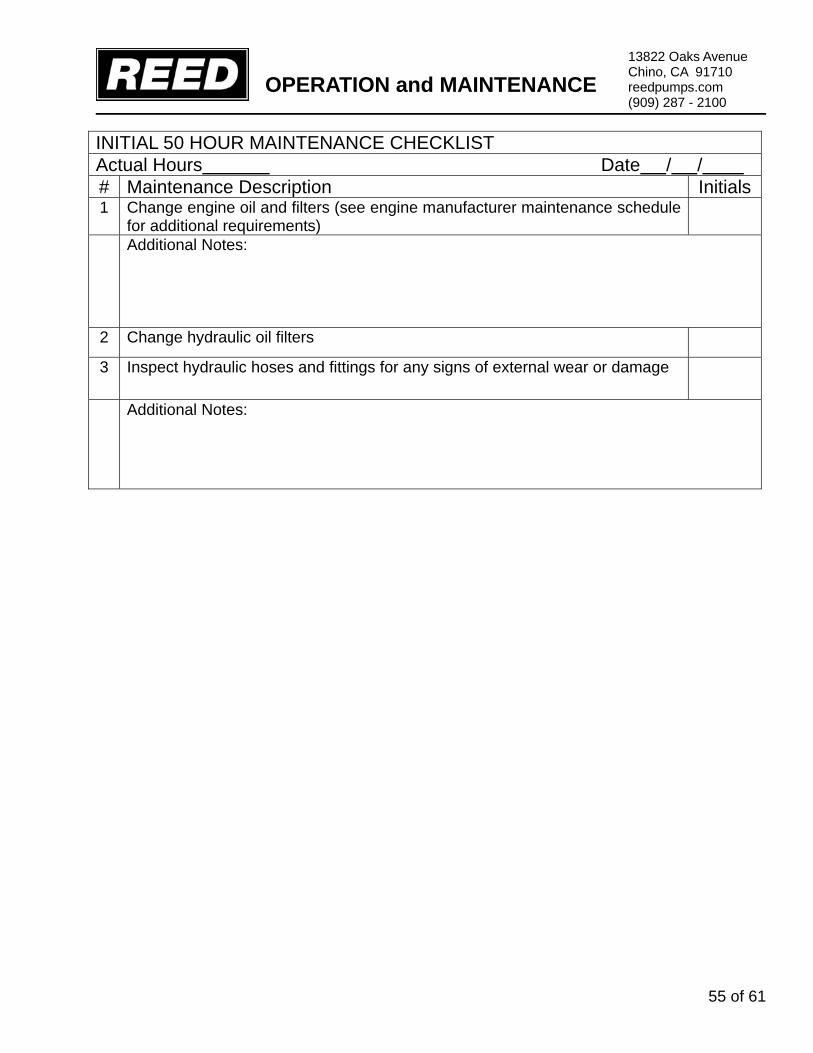
INITIAL 50 HOUR MAINTENANCE CHECKLIST Actual Hours Date / / # Maintenance Description Initials1 Change engine oil and filters (see engine manufacturer maintenance schedule
for additional requirements)
Additional Notes:
2 Change hydraulic oil filters
3 Inspect hydraulic hoses and fittings for any signs of external wear or damage
Additional Notes:
OPERATION and MAINTENANCE
56 of 61
13822 Oaks Avenue Chino, CA 91710 reedpumps.com (909) 287 - 2100
EVERY 100 HOUR MAINTENANCE CHECKLIST Actual Hours Date / / # Maintenance Description Initials1 Clean hydraulic tank breather 2 Inspect all structural components (check frame, hopper, axle, hood, towing
hook, and other structural members for any damage)
Additional Notes:
3 Adjust “S-Tube Nut” or “Castle Nut” (refer to “S-Tube Adjustment” in Maintenance Section)
Additional Notes:
4 Change flush box oil and examine for excessive amounts of contamination (excessive contamination might indicate need to change the Piston Cups)
Additional Notes:
5 Check coolers and radiators for dirt or debris. Clean as necessary
6 Check condition of engine drive belts. Change if necessary (see engine manufacturer maintenance schedule for additional requirements)
Additional Notes:
OPERATION and MAINTENANCE
57 of 61
13822 Oaks Avenue Chino, CA 91710 reedpumps.com (909) 287 - 2100
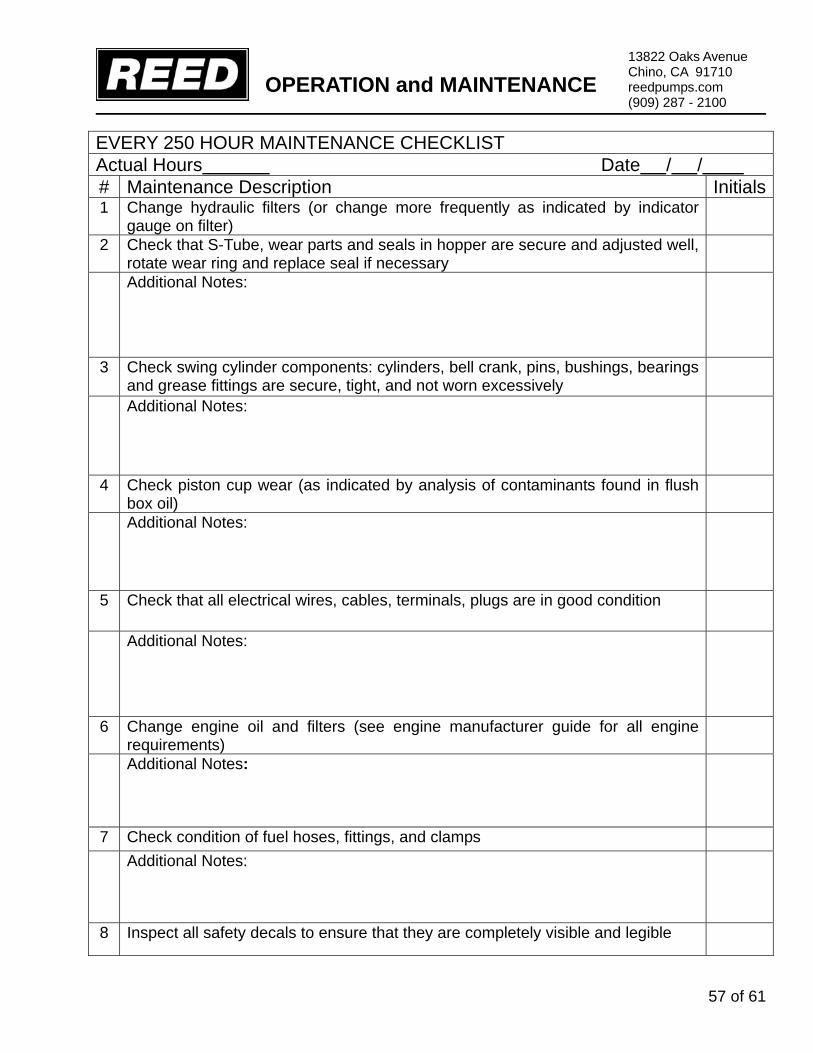
EVERY 250 HOUR MAINTENANCE CHECKLIST Actual Hours Date / / # Maintenance Description Initials1 Change hydraulic filters (or change more frequently as indicated by indicator
gauge on filter)
2 Check that S-Tube, wear parts and seals in hopper are secure and adjusted well, rotate wear ring and replace seal if necessary
Additional Notes:
3 Check swing cylinder components: cylinders, bell crank, pins, bushings, bearings and grease fittings are secure, tight, and not worn excessively
Additional Notes:
4 Check piston cup wear (as indicated by analysis of contaminants found in flush box oil)
Additional Notes:
5 Check that all electrical wires, cables, terminals, plugs are in good condition
Additional Notes:
6 Change engine oil and filters (see engine manufacturer guide for all engine requirements)
Additional Notes:
7 Check condition of fuel hoses, fittings, and clamps
Additional Notes:
8 Inspect all safety decals to ensure that they are completely visible and legible
OPERATION and MAINTENANCE
58 of 61
13822 Oaks Avenue Chino, CA 91710 reedpumps.com (909) 287 - 2100
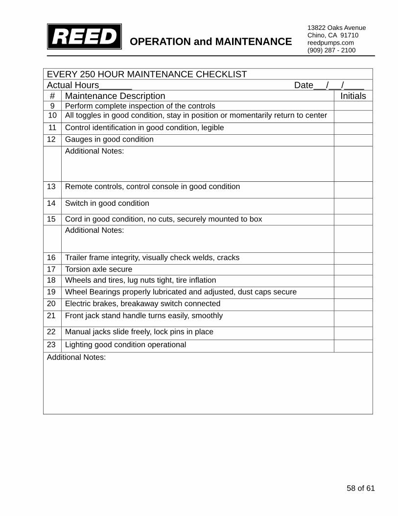
EVERY 250 HOUR MAINTENANCE CHECKLIST Actual Hours Date / / # Maintenance Description Initials 9 Perform complete inspection of the controls
10 All toggles in good condition, stay in position or momentarily return to center
11 Control identification in good condition, legible
12 Gauges in good condition
Additional Notes:
13 Remote controls, control console in good condition
14 Switch in good condition
15 Cord in good condition, no cuts, securely mounted to box
Additional Notes:
16 Trailer frame integrity, visually check welds, cracks
17 Torsion axle secure 18 Wheels and tires, lug nuts tight, tire inflation
19 Wheel Bearings properly lubricated and adjusted, dust caps secure
20 Electric brakes, breakaway switch connected
21 Front jack stand handle turns easily, smoothly
22 Manual jacks slide freely, lock pins in place
23 Lighting good condition operational
Additional Notes:
OPERATION and MAINTENANCE
59 of 61
13822 Oaks Avenue Chino, CA 91710 reedpumps.com (909) 287 - 2100
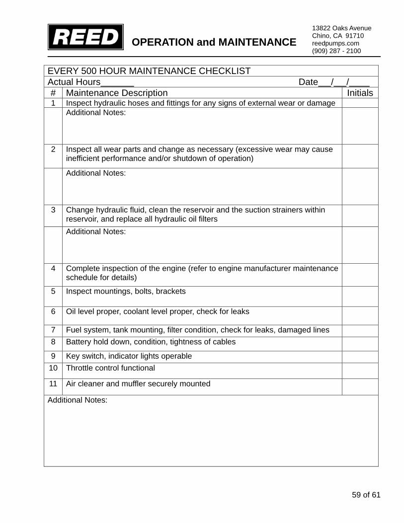
EVERY 500 HOUR MAINTENANCE CHECKLIST Actual Hours Date / / # Maintenance Description Initials1 Inspect hydraulic hoses and fittings for any signs of external wear or damage Additional Notes:
2 Inspect all wear parts and change as necessary (excessive wear may cause inefficient performance and/or shutdown of operation)
Additional Notes:
3 Change hydraulic fluid, clean the reservoir and the suction strainers within reservoir, and replace all hydraulic oil filters
Additional Notes:
4 Complete inspection of the engine (refer to engine manufacturer maintenance schedule for details)
5 Inspect mountings, bolts, brackets
6 Oil level proper, coolant level proper, check for leaks
7 Fuel system, tank mounting, filter condition, check for leaks, damaged lines
8 Battery hold down, condition, tightness of cables
9 Key switch, indicator lights operable
10 Throttle control functional
11 Air cleaner and muffler securely mounted
Additional Notes:
OPERATION and MAINTENANCE
60 of 61
13822 Oaks Avenue Chino, CA 91710 reedpumps.com (909) 287 - 2100
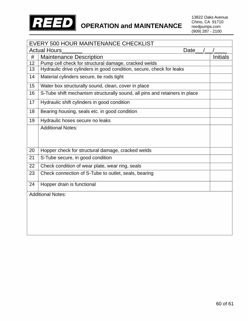
EVERY 500 HOUR MAINTENANCE CHECKLIST Actual Hours Date / / # Maintenance Description Initials
12 Pump cell check for structural damage, cracked welds 13 Hydraulic drive cylinders in good condition, secure, check for leaks
14 Material cylinders secure, tie rods tight
15 Water box structurally sound, clean, cover in place
16 S-Tube shift mechanism structurally sound, all pins and retainers in place
17 Hydraulic shift cylinders in good condition
18 Bearing housing, seals etc. in good condition
19 Hydraulic hoses secure no leaks
Additional Notes:
20 Hopper check for structural damage, cracked welds
21 S-Tube secure, in good condition
22 Check condition of wear plate, wear ring, seals
23 Check connection of S-Tube to outlet, seals, bearing
24 Hopper drain is functional
Additional Notes:
OPERATION and MAINTENANCE
61 of 61
13822 Oaks Avenue Chino, CA 91710 reedpumps.com (909) 287 - 2100
EVERY 500 HOUR MAINTENANCE CHECKLIST Actual Hours Date / / ADDITIONAL GENERAL NOTES: