china renewable energy development project photovoltaic...
TRANSCRIPT
solar photovoltaic systems and photovoltaic/wind hybrid systems specifications and qualifying requirements
GEF/WB-Assisted China Renewable Energy Development Project 4
CHINA RENEWABLE ENERGY DEVELOPMENT PROJECT PHOTOVOLTAIC MARKET DEVELOPMENT COMPONENT
SOLAR PHOTOVOLTAIC SYSTEMS
and PHOTOVOLTAIC/WIND HYBRID SYSTEMS
SPECIFICATIONS AND QUALIFYING REQUIREMENTS
Approved date: March 23,1999
PROJECT MANAGEMENT OFFICE (PMO) GEF/ WORLD BANK - ASSISTED CHINA RENEWABLE ENERGY
DEVELOPMENT PROJECT STATE ECONOMIC AND TRADE COMMISSION
solar photovoltaic systems and photovoltaic/wind hybrid systems specifications and qualifying requirements
GEF/WB-Assisted China Renewable Energy Development Project 5
PREFACE China Renewable Energy Development Project – Photovoltaic (PV) Market Development Component is implemented by the State Economic and Trade Commission of China (SETC) with assistance from the World Bank and the Global Environment Facility (GEF). The PV Component will support the sale and installation of about 10 MWp (about 300,000 to 500,000 sets) solar PV systems (PV) in north-western part of China. The purpose of the project is to improve the quality, lower the cost and enlarge the market for the PV by supporting PV companies as they develop the market and strengthen their service network. In addition, the project also supports technology improvement, industrialization and commercialization of the PV in China. To guarantee that the project will result in the use of improved technology and increase product quality, an Experts Committee, in which both Chinese and international experts were involved, was set up. After consulting with national and international PV industries, research institutes and independent test institutions, and obtaining comments from various sources, this document: "Solar Photovoltaic Systems and Photovoltaic/Wind Hybrid Systems Specifications and Qualifying Requirements," dated December 7, 1998 (here after called PV Spec) was completed. This PV Spec require solar modules, batteries and micro-wind turbine to meet existing national or international standards. Controllers of PV and Wind-PV systems, DC/AC inverters and DC lights, for which the national standards have not been issued, are required to meet the specifications detailed in the PV Spec. Only components that meet the required standards detailed in this document can be supported under the PV Market Development Component. We sincerely seek your help in the further improvement to the PV Spec.
PROJECT MANAGEMENT OFFICE (PMO) GEF/WORLD BANK-ASSISTED CHINA RENEWABLE ENERGY DEVELOPMENT PROJECT
STATE ECONOMIC AND TRADE COMMISSION ___________________________________________________________________________ Contact: PMO Renewable Energy Division, Resources Saving and Comprehensive Utilization Department, State Economic and Trade Commission 26 Xuanwumen Xidajie, Beijing 100053 Tel.: +86-10-63193469, 63193470 FAX: +86-10-63193460 E-mail: [email protected]
solar photovoltaic systems and photovoltaic/wind hybrid systems specifications and qualifying requirements
GEF/WB-Assisted China Renewable Energy Development Project 6
NAME LIST OF STANDARD COMMITTEE Chairman: Profesor Cui Rongqiang Solar Energy Research Institute, Shanghai Jiaotong University Secretary: Wang Sicheng Senior Engineer Energy Research Institute, State Development and Planning Commission Committee Member: Yu Peinuo Tianjin Institute of Power Source Wang Changgui Energy Research Institute, SDPC Wang Guohua Xinjiang New Energy Research Institute Li Anding Electric Power Engineering Research Institute, Chinese Academy
of Science Li Junfeng Renewable Energy Development Center, Energy Research
Institute, SDPC Yu Shijie Hefei Polytechnic University Zhang Danping Gansu Natural Energy Research Institute Zhang Zhengmin Renewable Energy Development Center, Energy Research
Institute, SDPC Lin Anzhong Beijing General Institute for Non-Ferrous Metals Luo Zanji Qinghai New Energy Research Institute Zhao Yuwen Beijing Solar Energy Research Institute Qin Jianping Inner-Mongolia Livestock Machinery Research Institute
International Expert Timonthy Ball Applied Power Corporation, USA Senior Advisors Zhu Junsheng PMO, State Economic and Trade Commission (SETC) Liu Hongpeng Renewable Energy Division, SETC Anil Cabraal Asia Alternative Energy Program, The World Bank
solar photovoltaic systems and photovoltaic/wind hybrid systems specifications and qualifying requirements
GEF/WB-Assisted China Renewable Energy Development Project 7
TABLE OF CONTENTS PREFACE ....................................................................................................................................................................5
TABLE OF CONTENTS ............................................................................................................................................7
ACRONYMS................................................................................................................................................................8
1. OVERVIEW.........................................................................................................................................................9
1.1 PROGRAM OBJECTIVE.................................................................................................................................9 1.2 SYSTEM DESCRIPTION................................................................................................................................9 1.3 SCOPE OF SUPPLY AND SERVICES.............................................................................................................11 1.4 QUALIFYING SYSTEMS..............................................................................................................................12 1.5 CERTIFICATION REQUIREMENTS...............................................................................................................12 1.6 ENVIRONMENTAL .....................................................................................................................................12 1.7 WARRANTIES............................................................................................................................................13
2. SYSTEM REQUIREMENTS ...........................................................................................................................13
2.1 GENERAL..................................................................................................................................................13 2.2 SYSTEM SPECIFICATIONS..........................................................................................................................13
3. COMPONENT SPECIFICATIONS ................................................................................................................18
3.1 PHOTOVOLTAIC MODULES.......................................................................................................................18 3.2 BATTERY STORAGE..................................................................................................................................19 3.3 CHARGE CONTROLLER FOR PV SYSTEM...................................................................................................19 3.4 FLUORESCENT LAMPS...............................................................................................................................20 3.5 DC/AC INVERTERS..................................................................................................................................21 3.6 WIND TURBINE.........................................................................................................................................22 3.7 CHARGE REGULATOR FOR WIND TURBINE...............................................................................................23
4. DOCUMENTATION REQUIREMENTS.......................................................................................................24
4.1 USER’SMANUAL .......................................................................................................................................24 4.2 TECHNICIAN’SMANUAL FOR INSTALLATION, OPERATIONS AND MAINTENANCE......................................24 4.3 WARRANTY CERTIFICATES.......................................................................................................................25
5.0 SYSTEM DATA SHEET ..............................................................................................................................26
5.1 GENERAL..................................................................................................................................................26 5.2 WARRANTIES............................................................................................................................................26 5.3 SPECIFICATIONS........................................................................................................................................26 5.4 DOCUMENTATION...................................................................................................................................30 5.5 EXCEPTIONS AND DEVIATIONS ...............................................................................................................30
solar photovoltaic systems and photovoltaic/wind hybrid systems specifications and qualifying requirements
GEF/WB-Assisted China Renewable Energy Development Project 8
ACRONYMS
A Amp AC Alternating Current Ah Amp-hours DC Direct Current DOD Deep of Discharge GEF Global Environment Facility GOC Government of China HVD High Voltage Disconnection IEC International Electro-technical Committee IEEE Institute for Electrical and Electronics Engineers ISO International Standards Organization I-V Amp - Voltage LCD Liquid Crystalline Display LED Light Emitting Diode Lm Lumen LVD Low Voltage Disconnection KHz Frequency km/hr Unit of Wind Speed mA Mili-amps MSTC Ministry of Science and Technology MWp Megawatt Peak PMO Project Management Office PV Photovoltaics SETC State Economic and Trade Commission SDPC State Development and Planning Commission PV Solar Photovoltaics (refers to both stand-alone PV systems and PV-
wind hybrids in this document) V Volts VA Voltage Amp W Watts Wp Watt Peak
solar photovoltaic systems and photovoltaic/wind hybrid systems specifications and qualifying requirements
GEF/WB-Assisted China Renewable Energy Development Project 9
1. Overview 1.1 Program Objective
1. Renewable energy is a critical component of China’s long-term energy strategy for rural development. China has strongly supported small hydropower, biomass, and small wind turbines over the past 35 years, to provide energy and electricity to isolated rural populations. In 1995, the government of China (GOC) voiced new commitment to renewable energy, as outlined in the New and Renewable Energy Development Program, 1996-2010, developed by the State Development Planning Commission, the Ministry of Science and Technology Commission and the State Economic and Trade Commission (SETC). This program aims at improving the efficiency of renewable energy technology applications, lowering production costs and enlarging the contribution of renewable energy to overall energy supply. The 1995 Electricity Law also extends GOC support to solar, wind, geothermal and biomass energy for power. Recognizing the need for a strategic orientation to renewable energy development, the GOC, with World Bank/GEF assistance, has undertaken detailed studies. These studies identified solar photovoltaics as a priority renewable energy technology for China’s or off grid electricity service in the near term and as a technology for distributed and bulk power generation in the longer term.
2. The Renewable Energy Project design is based on these studies, which conclude that China
needs a market-driven approach to renewable energy development which: a) focuses on promoting commercial or near-commercial applications; b) combines international advances in technology with demonstrated Chinese low-cost production capabilities; and c) taps the large potential demand by lowering costs and improving products, system reliability, and consumer service.
3. The aim of the program is to develop state of the art wind and solar PV technology and
businesses, to increase electricity supply in an environmentally sustainable way, and to improve access of dispersed rural households and institutions to modern energy. The PV component consists of GEF grant-financed sub-components to enable the purchase of PV systems by rural consumers and several complementary technical assistance activities including mechanisms to ensure quality products and services to consumers, to improve the capacity of participating companies, and to support monitoring and evaluation. The GEF grant would support the sale of an aggregate of 10 MWp of photovoltaic (PV) systems (PV stand-alone or PV/wind hybrid) in Northwestern provinces principally in Qinghai, Gansu, Inner Mongolia, Xinjiang, Tibet provinces, but extent to adjacent districts in Sichuan province. The component would catalyze the creation of a potential large scale market for photovoltaic (PV) and PV/wind hybrid systems and pave the way for establishment and growth of commercially oriented companies to serve this market.
4. This document presents the specifications and qualifying requirements for the equipment,
systems and services to be provided by companies participating in this program. The objective of the specifications is to set minimum standards of safety, quality, reliability and performance of the PV system and components to ensure consumer satisfaction.
1.2 System Description
solar photovoltaic systems and photovoltaic/wind hybrid systems specifications and qualifying requirements
GEF/WB-Assisted China Renewable Energy Development Project 10
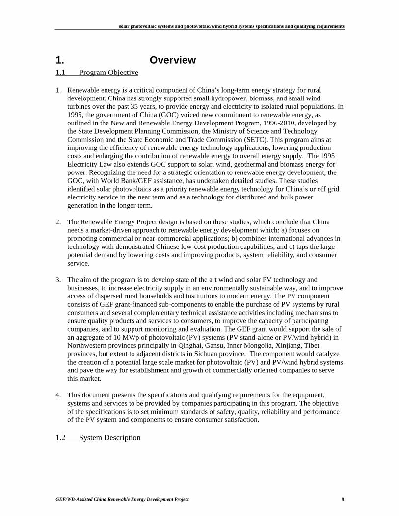
1. The PV1 systems covered by this specification will operate at nominal voltages of 48 Vdc or less and provide power for lights, black and white TV, and radio/cassette or similar appliances for about three to five hours a day in accordance with local solar resources and load consumption. Larger systems provide for additional light fixtures and a DC/AC inverter may be supplied to power other household appliances. Hybrid systems, which consist of small wind turbines (100-300W) and one or more PV modules, offer increased energy output at a lower cost in locations with good wind and solar resources. Complete systems at a minimum must include a PV array consisting of one or more modules, a rechargeable battery bank, controls, circuit protection, and lighting fixtures. Hybrid systems include a wind turbine and wind controller in addition to other components.
The following diagrams illustrate the possible system types:
Fig.1 DC PV System
CHARGECONTROLLER
BATTERY
DC LOAD
SOLARMODULE
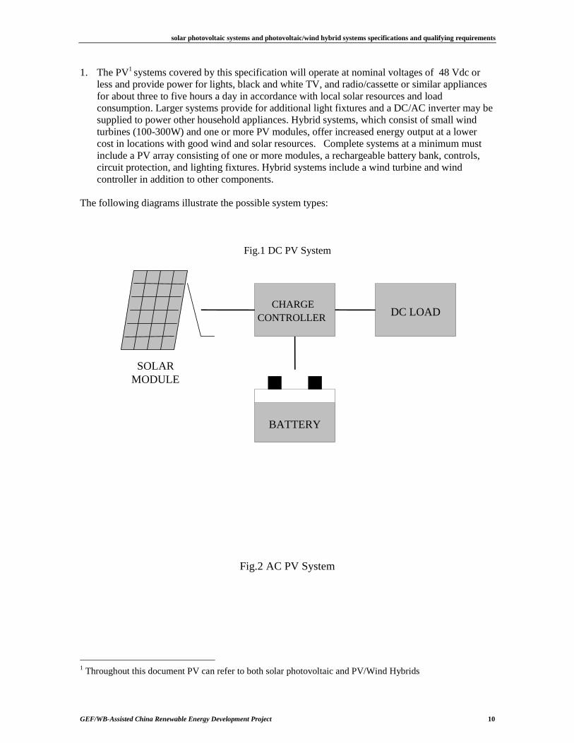
Fig.2 AC PV System
1 Throughout this document PV can refer to both solar photovoltaic and PV/Wind Hybrids
solar photovoltaic systems and photovoltaic/wind hybrid systems specifications and qualifying requirements
GEF/WB-Assisted China Renewable Energy Development Project 11
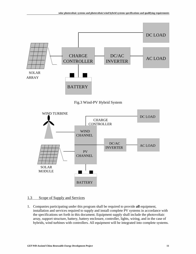
Fig.3 Wind-PV Hybrid System
1.3 Scope of Supply and Services
1. Companies participating under this program shall be required to provide all equipment, installation and services required to supply and install complete PV systems in accordance with the specifications set forth in this document. Equipment supply shall include the photovoltaic array, support structure, battery, battery enclosure, controller, lights, wiring, and in the case of hybrids, wind turbines with controllers. All equipment will be integrated into complete systems.
CHARGECONTROLLER
BATTERY
DC/ACINVERTER
AC LOAD
DC LOAD
SOLARARRAY
WINDCHANNEL
PVCHANNEL
BATTERY
DC/ACINVERTER
AC LOAD
DC LOAD
SOLARMODULE
WIND TURBINE
CHARGECONTROLLER
solar photovoltaic systems and photovoltaic/wind hybrid systems specifications and qualifying requirements
GEF/WB-Assisted China Renewable Energy Development Project 12
2. The supplier will provide the most appropriate system integration, components, assembly and packaging that meets all the requirements of this specification.
3. The PV shall be packaged and pre-wired to provide convenient installation at a remote
customer site by a supplier-trained technician. The system will be constructed such that a user can perform routine maintenance such as adding battery water and replacing light bulbs and fuses, and a technician can easily perform system diagnostics or replace components.
4. Each system must be packaged for shipping to prevent any shipping related damage. The
supplier will be responsible for settling any shipping related damaged claims and will be responsible for replacing damaged systems in a timely manner.
5. The specifications of the systems must be summarized and submitted using the specification
data sheets provided in Section 5. Any exceptions and variations to the specification must be explicitly stated. The scope and reasons for each listed exception and variation must be fully explained with supporting data.
6. Training is a critical aspect of the program and participating companies will be required to
develop and conduct a comprehensive training program which will cover training of service technicians, installers and end users. Participating companies will be required to submit documentation which describes in detail their training programs.
1.4 Qualifying Systems
1. This specification applies to standalone solar photovoltaic systems (PV) or PV/Hybrid systems with array capacities at least 10 watts and up to 500 watts and wind turbines with rated capacities up to 300 watts. Nominal system voltage (rated voltage) shall be less than 48VDC. Larger systems may be submitted to PMO for consideration.
1.5 Certification Requirements
1. Components to be financed under the World Bank/GEF assisted projects must be; (a) In accordance with this specification; b) Meet national and/or international safety and reliability standards; and (c) Tested and certified by an organization acceptable to the Government of China and the World Bank.
2. Any qualified testing institutions who are interested in this project should send applications to
the PMO for providing testing and certifying services for components to be used in this project. In general, organizations accredited according to ISO-25 requirements will be acceptable.
1.6 Environmental
1. Systems shall be designed and built to withstand the environmental conditions found in the western part of China (Qinghai, Gansu, Inner Mongolia, Xinjiang, Tibet and parts of Sichuan provinces). For design purposes, consider that temperature extremes could range from –35 to +55 degrees Centigrade with humidity levels of 90 percent. Operating temperatures for batteries and other electronic component controls shall range from -10° Centigrade to 40° Centigrade and humidity levels of 90 percent. Maximum altitudes reach 4500 meters above sea level. Array mounting structures and wind turbines, with the exception of portable systems, must be able to withstand wind gusts up to 120 km/h without damage. (Due to the high
solar photovoltaic systems and photovoltaic/wind hybrid systems specifications and qualifying requirements
GEF/WB-Assisted China Renewable Energy Development Project 13
altitudes, suppliers are advised to pay specific attention to pressure ranges of sealed batteries and limitations of temperature dissipation of heat sinks and electronic devices.)
1.7 Warranties
1. The supplier will provide at a minimum a one-year systemwarranty against defects, workmanship and installation. During this period, the supplier will be responsible for parts, labor, transport and all other cost associated with the repair or replacement of the system components. After the expiration of the system warranty, the supplier will be responsible only for component replacement, but not associated labor or transport cost, during the warranty periods for the key components indicated below.
2. Minimum acceptable manufacturer warranties for key components shall be:
a) PV modules greater than 20W: 10 years (power loss of not more than 10% of rated capacity over a ten year period)
b) PV modules 20W and lower: 5 years (power loss of not more than 10% of rated capacity over a five year period)
c) Controls: 2 years d) Inverters: 2 years e) Batteries: 1 year for automotive style batteries and sealed batteries of less than 100AH
and 2 years for industrial stationary batteries and other batteries greater than 100 AH. f) Wind turbines: 2 years g) Controller for wind turbine: 2 years
3. Manufacturer warranties, including modules, wind turbines, controls, inverters and batteries,
must be effective and transferable to the end users at time of installation.
2. System Requirements
2.1 General
1. This section provides a minimum set of requirements that must be followed in the design, specification and installation of qualifying systems. These specifications, when followed, will ensure adequate levels of safety, performance, reliability and system lifetime. System suppliers must adhere to these requirements in order to participate under this program.
2. This section focuses on the specifications that pertain to the system level. Detailed
specifications pertaining to individual components are listed in Section 3 of this document. 2.2 System Specifications
2.2.1 Array
1. The photovoltaic array will consist of one or more flat-plate photovoltaic modules. If more than one module is used, they must be identical; modules must be selected with voltage and current characteristics which limit mismatch2 losses to less than 2%.
2 Mismatch Loss refers to loss in the total power output when connecting PV modules in series or parallel.
solar photovoltaic systems and photovoltaic/wind hybrid systems specifications and qualifying requirements
GEF/WB-Assisted China Renewable Energy Development Project 14
2. Modules should be framed in such a way as to allow secure connection to the module mounting structure and allow removal of an individual module from the support structure for replacement.
3. The module(s) should be mounted on a support structure made of corrosion resistant material capable of providing a stable and secure attachment. The PV array and support structure should be able to withstand wind gusts up to 120 km/hour without damage, except for portable systems.
4. The structure should be mounted at a fixed angle and oriented to maximize the useful energy supplied to the user during the design month (i.e., the month with the worst average daily irradiation).
5. All array fasteners shall be stainless steel, galvanized steel, nylon or other corrosion resistant material that provides the required mechanical strength to securely affix modules to the support structure. Roof mounted arrays should have a minimum clearance of 10cm between the PV array and the roofing material. Anchoring of roof mounting structures should be to the building substructure and not to the roofing material.
6. Ground mounted arrays should have a minimum clearance of at least 1.2 meters between the array and ground. Array foundations should be firmly affixed to a foundation that has been designed to withstand wind-loads on the array.
7. Portable systems shall include an array support that allows the user to fix the tilt angle and secure the module facing south.
2.2.2 Batteries
1. The rechargeable battery bank should consist of one or more batteries in series, but no more than four identical batteries connected in parallel. Acceptable battery types include deep cycle lead acid, sealed lead acid and Nickel Cadmium types. Batteries should be designed to provide a minimum useful life longer than warranty years under anticipated operating conditions. Suppliers should submit documentation, including cycle life analysis, that demonstrates compliance with this requirement. When the capacity has decreased to 80% of its rated value, the battery will be considered to be at the end of its useful lifetime.
2. Deep cycle lead acid batteries suitable for use in photovoltaic systems are the preferred, but
shallow cycle automobile type batteries can be used if the supplier can clearly demonstrate that the battery will meet all stated requirements . Battery banks should consist of no more than 4 parallel strings of series connected batteries.
3. Minimum battery capacity shall be determined to provide a minimum 3 days of storage.
System design shall limit the maximum depth of discharge (DOD) for deep cycle batteries to 80% of rated capacity and 50% DOD for shallow cycle types.
4. Batteries should be interconnected using lead plated copper buss bars or flexible copper
conductors. Batteries should be equipped with flag terminals suitable for bolted connections. Anti-oxidant grease should be applied to battery terminals to prevent corrosion. Positive and negative polarity should be clearly marked.
5. The batteries can be supplied either in a wet-charged or dry-charged condition. If dry-charged,
all chemicals and electrolyte must be supplied in accordance with battery manufacturer specifications.
solar photovoltaic systems and photovoltaic/wind hybrid systems specifications and qualifying requirements
GEF/WB-Assisted China Renewable Energy Development Project 15
6. Batteries and associated containers should be packaged to withstand transport down rough roads without damage to the battery or spillage of electrolyte.
7. Sealed batteries used in installations above 2500 meters in altitude must be certified by the
manufacturer as suitable for such service. 8. Suppliers must submit data and specification sheets from the battery manufacturer that
demonstrates compliance with all the above stated requirements. 2.2.3 Battery Enclosure
1. The batteries should be housed in a vented compartment that prevents users from coming in contact with battery terminals or battery electrolyte. This compartment should be strong enough to accommodate the weight of the battery. A mechanism to prevent opening and entry of the battery enclosure by children shall be provided.
2. All parts of the compartment subject to contact with battery acid should be acid resistant. The
entire enclosure must be constructed to last at least 5 years without maintenance. The battery enclosure should have a clean and neat appearance so that end users would not reasonably object to having the battery enclosure located within sight of a living space.
2.2.4 Circuit Protection and Charge Control
1. Systems should be designed or include devices to protect users and system components from damage through a combination of proper design, user instruction/training and/or use of specific components. These include protection from: short circuit of loads; reverse polarity of loads, module or battery; internal shorts in charge controller, inverter, or other devices; lightning induced transients; and nighttime discharge of the battery due to reverse current through the array. For example, the requirement for protection against battery overcharge and excess water loss could be met in small systems by careful selection of module and battery capacities and by proper user training or by use of an electronic charge regulator. For systems with PV arrays greater than 20Wp or where wind turbines are used, protection will be provided by a charge controller incorporating a high voltage disconnect (HVD), low voltage disconnect (LVD) and circuit protection. Devices that integrate the above into a single device are strongly encouraged, but alternate approaches will be considered.
2.2.5 System Status Indication
1. Some form of an indicator shall be provided to indicate to user approximate battery state of charge. This device should, at a minimum, indicate the following: a) Fully Charged: Indication when PV charging has been reduced or terminated due to a
fully charged battery. b) Battery Low: Indication when the battery level is low and energy conservation steps
should be taken. c) Load Disconnect: Indication when the load has been disconnected due to a low battery
state of charge. 2. The indicators may be LED’s, analog or digital meters, or audible alarm. The chosen device
should come appropriately labeled so that the user does not have to refer to a manual to understand the existing battery condition.
solar photovoltaic systems and photovoltaic/wind hybrid systems specifications and qualifying requirements
GEF/WB-Assisted China Renewable Energy Development Project 16
2.2.6 DC/AC Inverters
Inverters with sine-wave outputs are preferred but not required as long as suppliers can demonstrate that the proposed inverter is suitable for powering the anticipated AC loads. 2.2.7 Wind Turbine
1. Wind turbines must be supplied with supporting tower designed to safely support the wind turbine under the maximum anticipated wind speed (120 km/hr).
2. Support towers must be constructed of corrosion resistant materials and utilize galvanized or
stainless steel hardware. Painted steel structures are acceptable for other than coastal environments.
3. Wind turbine foundations must be designed to safely support the wind turbine towers under
design wind speed. 4. Installation of wind turbine shall be in accordance with Chinese National Standard: UDC,
2BFF1101-89 (Installation Requirements for Low Speed Wind Generators). 5. Wind turbine systems shall include a charge regulator that adheres to the requirements listed
above under circuit protection and charge controls and meets the wind controller specifications listed in Section 3.
6. Location and installation of the wind turbine shall adhere to the following requirements:
a) Wind turbine shall be installed in locations not frequently accessed by people or livestock. The minimum distance measured from the ground to the bottom of the rotor arc shall be 3 meters.
b) Wind turbines shall be installed in open areas without obstructions that would limit wind flow or create turbulence.
c) While considering the above requirements, the installation site should be as near as possible to user’s house to minimize energy loss in wiring between the wind turbine and batteries.
d) Wind turbines and towers shall be electrically grounded and incorporate adequate lightning protection to protect users and equipment.
7. Wind turbines should not produce noise at levels that would be reasonably unacceptable to the
end user. In most installations the noise level should be less than 65dB when 30 meters from the turbine.
8. Wind turbines shall include controls or mechanisms that protect the system from over speed
during high wind conditions and over charging of the battery. Specifications for wind turbine charge controllers is provided in Section 3.
2.2.8 Lamps
1. Each system shall include one or more lamp. Lamps are to be installed, or customers instructed to locate the lamp in a location that provides the maximum benefit to the user. Lamps should optimize the amount of useful light projected on the illuminated area by use of high efficiency reflectors, fixture shape or other appropriate means.
solar photovoltaic systems and photovoltaic/wind hybrid systems specifications and qualifying requirements
GEF/WB-Assisted China Renewable Energy Development Project 17
2. For general or area lighting, lamps shall utilize fluorescent tubes and electronic ballast. Each lamp should have its own ballast. Special purpose lights may be used as long as they provide similar levels of efficiency and lifetime.
3. Ballast should be designed to protect against reverse polarity connections. 4. Lamps should be resistant to insects, corrosion and moisture. 5. Lens covers should be easily removable by user for bulb replacement and cleaning. 6. The design of the lamp must allow for tube replacement without risk to the user of coming in
contact with any electrical component or contacts that could injure the user or damage the fixture.
7. Ballast that pre-heat the electrodes of the lamp before applying the high voltage for ignition are
preferred. 8. Providing the consumer with a spare fluorescent tube, especially if tube rated lifetime is shorter
than 2000 hours is recommended. 2.2.9 Wiring
1. Stranded and flexible insulated copper wiring should be used. All wiring should be suitable for its intended uses and labeled as such, (for example, sunlight resistant, direct burial, water resistant, etc.)
2. For permanent installations, all wiring should be in conduits wherever wiring would be exposed
to damage. Exposed wiring is acceptable in protected locations if it is firmly fastened to the building structure using suitable insulated wire staples or straps. Wiring through roofing, walls and other structures should be protected through the use of conduit. Wiring through roofing should form a waterproof seal.
3. Field-installed wiring should be joined using terminal strips or screw connectors. Wire nuts
may be used only in indoor locations in appropriate junction boxes or enclosures. The rated current carrying capacity of the connector should not be less than the circuit current rating. All connections must be made in junction boxes. Light fixtures, switches, and socket outlet housings may be used as junction boxes where practical.
4. All wiring should be color coded and/or labeled. 5. All wiring should be sized to keep line voltage losses to less than 3% in each sub-circuit and to
allow the circuit to operate within the rated amperage capacity of the wire and be mechanically strong.
2.2.10 Load connections or outlets
1. A simple and safe means for connection of user supplied loads should be provided. Acceptable methods for load connections include insulated terminal strips or receptacles.
2. Polarity should be clearly marked for user connection points.
solar photovoltaic systems and photovoltaic/wind hybrid systems specifications and qualifying requirements
GEF/WB-Assisted China Renewable Energy Development Project 18
3. Load connection points should provide short circuit and reverse polarity protection of user connected loads where possible.
4. Current limiting devices, either fuses, circuit breaker or electronic protection should limit the
current available to user load of less than the estimated amp capacity of the wiring sizes of the loads to be applied. For most cases, current protection of user connection points should be limited to 10A or less.
2.2.11 Installation, Packaging and Shipment
1. All systems shall be installed in accordance with this document, good industry practice, all applicable local and national codes, and standards by qualified and trained technicians. In general, installation practice should insure high levels of system reliability and user satisfaction.
2. Each system must be packaged for shipping to prevent any shipping related damage. The
supplier will be responsible for settling any shipping related damaged claims and will be responsible for replacing damaged systems in a timely manner.
3. Component Specifications 3.1 Photovoltaic Modules
1. Each module shall utilize no less than 36 series-connected single or poly-crystalline silicon solar cells. Thin Film modules are not initially acceptable for use under this program. The PV modules must be manufactured in accordance with all mechanical, electrical and environmental requirements given in the following referenced standards. a) IEEE 1262-1995 Recommended Practice for Qualification of Photovoltaic Modules; b) IEC 1215 Crystalline silicon terrestrial photovoltaic modules - Design qualification and
type approval; c) Chinese Standard GB/T14007-92 (General Specification for Terrestrial-use Solar Cell
Module), GB/T 14009 (Measurement Procedures for Parameters of Solar Cell Modules) and GB 9535 (Environmental Test Methods for Terrestrial Silicon Solar Cell Module).
2. Modules must be certified at a testing facility, preferably accredited according to ISO-25
standard, and acceptable to the PMO and the World Bank, as meeting one of these referenced standards. A copy of the certificate should be provided.
3. In lieu of module certification, based on a case-by-case review and approval by the PMO, and
subject to "no objection" by the World Bank, the following are acceptable alternatives: a) Modules made in ISO 9001-certified facility and a Certificate of Conformance is issued
by a certification agency acceptable to the PMO and the World Bank. The Certificate of Conformance should state that the PV module manufacture used materials, manufacturing process, quality control and testing procedures that ensures the module will meet the requirements of one of these referenced standards.
b) Modules from the same model series if at least one model in the series has been certified and if a certification agency acceptable to the PMO and the World Bank will certify that the same materials, manufacturing process and quality control procedures used for the certified model are used for the other models in the series.
solar photovoltaic systems and photovoltaic/wind hybrid systems specifications and qualifying requirements
GEF/WB-Assisted China Renewable Energy Development Project 19
4. Modules must be factory equipped with either a) weather proof junction box with terminal strip that allows for safe and long-lasting wiring connection to the module or b) a factory installed output cable that connects to the module via a sealed weatherproof termination.
5. Each module must be labeled indicating at a minimum:
a) Manufacturer name b) Model Number c) Serial Number d) Peak Watt Rating at the standard conditions of 1000 W/m2 solar irradiance, airmass
(AM) 1.5 spectral distribution, 25C module temperature) e) Peak Voltage f) Peak Current g) Test standard(s) to which the module has been tested.
3.2 Battery Storage
1. Batteries must be certified by a Chinese recognized test facility to Chinese standards or by an ISO-25 certified testing facility to equivalent standards applicable for the proposed battery type. Chinese standards for batteries include: a) GB 5008.1-85 Automotive b) GB 13337.1-91 Stationary Vented c) YD/T 799-1996 Sealed Battery d) GB 9368-88 Nickel-Cadmium Alkaline Battery
2. The maximum permissible self-discharge rate for any battery type is 20 percent of rated
capacity per 3-month period at 25 degrees Centigrade. 3. Cycle life of the battery (i.e., before its residual life drops below 80 percent of the rated Ah
capacity), at 25 degree Centigrade must exceed 200 cycles for shallow cycle types or 600 cycles for deep cycle type when discharged down to an average depth of discharge (DOD) of 80 percent. Manufacturer documentation indicating cycle life of the proposed battery must be submitted.
4. Each battery must be labeled indicating at a minimum: Manufacturer, Model Number, rated
voltage and capacity. 3.3 Charge Controller for PV System
1. The charge controller and associated devices must be designed to provide an average service life of 10 years under normal operating conditions.
2. The maximum quiescent current draw of the controller, when no LEDs are illuminated, must
not exceed 1% of the controller rated charge current. (For example a charge controller with a 2.5A charging capacity would have a maximum quiescent current of 25mA).
3. Voltage drop across the charge controller when charging (PV to battery terminals) or
discharging (battery to load terminals) should be less than 5% of the nominal system voltage. 4. The charge controller set points must be factory preset with the set points applicable to the
specified battery characteristics to prevent battery over-charge (high-voltage-disconnect and
solar photovoltaic systems and photovoltaic/wind hybrid systems specifications and qualifying requirements
GEF/WB-Assisted China Renewable Energy Development Project 20
reconnect set points) or over-discharge (low-voltage-disconnect and reconnect set points). It is recommended that circuitry to allow periodic equalizing charging of the battery be provided. Control set points for charging, discharging and other functions must be sufficiently stable to insure proper operation of the device over the range of anticipated ambient temperatures where the device will be installed.
5. Controller should include the following protective features:
a) Battery overcharge and over-discharge protection b) Short circuit of any load c) Reverse polarity of any load d) Reverse polarity of module or battery e) Internal shorts in charge controller. f) Lightning induced transients when use in lightning-prone areas is expected. g) Nighttime discharge of the battery due to reverse current through the array.
6. Controller should be able to withstand voltages of 1.25 times the array nameplate open circuit voltage with the battery removed from the circuit for a 1 hour duration.
7. Controller should be able to withstand currents of 1.25 times the array nameplate short circuit
current for a 1 hour duration. For switching type regulators the switching element must be capable of switching this current level without damage.
8. Charge controls and associated devices must be able to withstand shocks and vibrations due to
shipping and transport. 9. Charge controllers and associated devices must be clearly labeled with the minimum
information: a) Manufacturer name and model b) Serial number c) Voltage and current ratings for device d) PV, battery and load connection points and polarity
10. Complete documentation for each charge controller must be included in the service technician’s
training manual and should include: a) Installation instructions b) Operating instructions c) Technical specifications and ratings d) Safety warnings e) Troubleshooting instructions f) Information pertaining to serviceable parts g) Warranty
3.4 Fluorescent Lamps
1. Lamps shall be capable of continuous operation under voltages ranging between 90% and 120% of nominal voltage.
2. Minimum operating voltage when the tube will start shall be at least 90% of the nominal rated
voltage.
solar photovoltaic systems and photovoltaic/wind hybrid systems specifications and qualifying requirements
GEF/WB-Assisted China Renewable Energy Development Project 21
3. Under 90% to 120% of the rated voltage, fluorescent lamps must provide a minimum tube lifetime of 1000 hours. The switching lifetime (on/off cycles) must be at least 1000 cycles.
4. Lamps should be protected against damage when operating under open circuit conditions (e.g.,
when the tube is removed or has failed). Current draw when operating with a failed or removed tube should be limited to less than 20% of nominal current consumption.
5. Lamp and ballast shall be protected against reverse polarity or the system as a whole shall
protect the lamp from damage if reverse polarity is applied. 6. Luminous efficacy requirements:
a) Under rated voltage, the luminous efficacy should not be less than 35L/W without cover and reflectors, after 100 hours of conditioning, and at an ambient temperature of 25 degrees Centigrade.
b) The luminous efficacy should not be less than 80% of its rated value throughout a voltage range 90% to 120% of nominal value.
7. The minimum operating frequency should be 20 kHz. 8. The electrical wave-form at the fluorescent lamp terminals must be symmetrical in time to
within 10 percent (i.e., 60%/40% wave-form maximum difference in symmetry) over the voltage range of 90% to 120% of nominal voltage at an ambient temperature of 25 degree Centigrade.
9. The maximum crest factor (ratio of peak to RMS voltage of the wave-form applied to the
fluorescent lamp) shall be no more than 2.0. 10. The lamp must be able to withstand shocks and vibrations due to shipping and transport. 11. Socket of the lamp should meet the requirements of international or GB standard (GB1312-91
technical requirements of lamp holders for tubular fluorescent lamps and starter-holders). 12. For lamps with metal covers, the insulation resistance between the cover and the fluorescent
tube terminals should meet IEC 598-1 requirements. 13. Insulating materials should comply with heat and fire resistance requirements stipulated in
Chapter 13 of GB7000.1. 14. Lamps should be marked with the manufacturer, model number, rated voltage, wattage and date
of manufacture or batch number. 3.5 DC/AC Inverters
1. Rated output voltage shall be AC220V±10% over the full range of normal battery operating voltages. That is, when the input DC voltage varies from 90% to 120%, the output AC voltage must be within 10% of the rated voltage.
2. Output frequency is 50Hz and the variation should not be over 5%. 3. Inverter shall be capable of:
solar photovoltaic systems and photovoltaic/wind hybrid systems specifications and qualifying requirements
GEF/WB-Assisted China Renewable Energy Development Project 22
a) Operating continuously for 4 hours at its rated power under ambient temperatures of 25° Centigrade.
b) Operate safely for at least one minute at 125% of rated power. c) Provide 150% of rated power for at least two 2 seconds to facilitate starting of motors
and other high capacitance loads. 4. If sine-wave inverters are utilized, the output waveform total harmonic distortion should be no
more than 5%. 5. Inverter efficiency when operating resistive loads and power levels of above 75% should be
greater than 80%. 6. Inverter or inverter circuits must include protection against:
a) Low voltage: when input voltage is less than 1.8V/battery cell. b) Over-current: when working current is greater than 150% of the rated current c) Short circuit of input and output terminals. d) Reverse polarity on DC input terminals. e) Lightning induced transients when use in lightning-prone areas is expected.
7. The maximum quiescent current draw of the inverter, when no LEDs are illuminated, must not
exceed 3% of the rated input current of the inverter.
8. Quiet operation: The noise produced by the inverter should be no more than 65dB at a distance of 3 meters from the inverter.
9. Easy to service: The inverter should be easy to repair or replace in the field by the service
technicians. 10. The inverter input and output terminals must not be exposed to contact by the user and must be
securely mounted in a location which is not accessible by children. 11. Each inverter must be labeled with the minimum information:
a) Manufacturer name and model b) Serial number c) Input and output voltage and rated power d) Battery and load connection points and polarity
12. Complete documentation for the inverter must be included in the service technicians training
manual and should include: a) Installation instructions b) Operating instructions c) Technical specifications and ratings d) Safety warnings e) Troubleshooting instructions f) Information pertaining to serviceable parts g) Warranty
3.6 Wind Turbine
1. Only 100W to 300W micro wind turbines can be used in this project. Wind turbines must meet the requirements of Chinese National Standard GB/T13981-92 (General Requirements for
solar photovoltaic systems and photovoltaic/wind hybrid systems specifications and qualifying requirements
GEF/WB-Assisted China Renewable Energy Development Project 23
Wind Turbine Design), GB10760.1-89 (Specification Requirements for Small Wind Generators), and GB/T 16437-1996 (Safety Requirements for Supporting Structure of Small Wind Turbine). Wind turbines must be classified and tested in accordance with Industry Standard JB/NQ35.1-87�JB/NQ35.2-87�JB/NQ35.3-87 (Qualification Classified Requirements for Wind Generators).
2. Wind turbines must be marked with the manufacturer, model number, rated voltage, wattage
and date of manufacture or batch number. 3.7 Charge Regulator for Wind Turbine
1. The charge controller and associated devices should be designed for a life of 10 years under normal operating conditions.
2. Charge controllers must be able to withstand input power of 2 times the rated wind power. 3. Charge controllers must be equipped with an electric load, or other suitable mechanism to
prevent turbine over-speed when battery has been fully charged. If an electric load is used for regulation it shall have a power rating equal to or greater than the rated power of the wind turbine.
4. The controller must include current limitation circuit to avoid damage by sudden increases of
voltage or current due to turbine over-speed. 5. The charge controller set points must be factory preset with the set points applicable to the
specified battery characteristics to prevent battery over-charge (high-voltage-disconnect and reconnect set points) or over-discharge (low-voltage-disconnect and reconnect set points). It is recommended that circuitry to allow periodic equalizing charging of the battery be provided. Control set points for charging, discharging and other functions must be sufficiently stable to insure proper operation of the device over the range of anticipated ambient temperatures where the device will be installed.
6. Controller should include the following protective features
a) Battery overcharge and over-discharge protection b) Short circuit of any load c) Reverse polarity of any load d) Reverse polarity of turbine or battery e) Internal shorts in charge controller, inverter, or other devices f) Lightning induced transients when use in lightning-prone areas is expected.
7. Maximum current draw of the controller, when no LEDs are illuminated, must not exceed 1%
of the controller rated charge current. 8. Voltage drop across the charge controller when charging (Wind turbine to battery terminals) or
discharging (battery to load terminals) should be less than 5% of the nominal system voltage. 9. Charge controls and associated devices must be able to withstand shocks and vibrations due to
shipping and transport. 10. Charge controllers and associated devices must be clearly labeled with the minimum
information:
solar photovoltaic systems and photovoltaic/wind hybrid systems specifications and qualifying requirements
GEF/WB-Assisted China Renewable Energy Development Project 24
a) Manufacturer name and model b) Serial number c) Voltage and current ratings for device d) Wind turbine, battery and load connection points and polarity
11. Complete documentation for each charge controller must be included in the service technicians
training manual and should include: a) Installation instructions b) Operating instructions c) Technical specifications and ratings d) Safety warnings e) Troubleshooting instructions f) Information pertaining to serviceable parts g) Warranty
4. Documentation Requirements 1. Systems must be supplied with two types of documentation and warranty certificate. The first
is a USER’S MANUAL intended for the customers and will be included with each system. The second document, TECHNICIAN� INSTALLATION, OPERATIONS AND MAINTENANCE MANUAL will be for use by the service technicians and should include the specific details on installation, operation and maintenance.
2. Documents must be provided in both Chinese and the local minority’s language. The User’s
Manual documentation should be simple and easy to understand. Use of sketches or graphics is required for the User’s Manual.
4.1 User’s Manual
1. The User’s Manual shall contain, at a minimum:
• Simplified operating principles. The relationship between energy available on a daily basis and the sunlight conditions should be clearly and simply explained.
• A description of all user interactive hardware including disconnect switches and status indicators.
• Procedures for the proper system operation, including a list of load limitations and any problem loads.
• These procedures should include suggested system operation, including actions to be taken during periods of inclement weather, and/or a low voltage disconnect event. Documentation should provide instruction on care and maintenance of the array and prevention of shading of modules.
• Any user maintenance items. • Emergency shut down procedures and recommendations for extended periods of
system non-use. • A user trouble shooting guide.
4.2 Technician’s Manual for Installation, Operations and Maintenance
1. The technician’s manual shall contain, at a minimum:
solar photovoltaic systems and photovoltaic/wind hybrid systems specifications and qualifying requirements
GEF/WB-Assisted China Renewable Energy Development Project 25
• A detailed description of the proposed system’s dimensions and weights. • A complete copy of the USER’S MANUAL. • A complete list of all system components, with associated manufacturers literature,
specifications, and warranties. Module IV curve and the battery charge/discharge curves (e.g., voltage and specific gravity as a function of state of charge) should be supplied.
• Complete installation instructions. • A recommended post-installation acceptance test procedure, including all appropriate
set points and test procedures. One must: − Verify that the installation of the photovoltaic array with regard to position,
direction, inclination and shading avoidance will maximize energy generation. − Ensure that the battery has received an equalization charge just before installation. − Use a shunt to measure the current from the array under charging conditions to
verify the array charging current. This measurement should be done under clear sky conditions.
− Test all of the loads for proper operation. − Make system-wide voltage drop measurements in the sub-circuits to verify that
connections meet the required maximum allowable voltage drop. − Note all measurements in the installation log. − Explain to the user the system operating principles, load management
requirements, impact of shading of the array and how to check and avoid it, user maintenance checks and how to conduct them.
• A recommended annual maintenance schedule, with complete maintenance instructions.
• A detailed troubleshooting guide referencing all the system components. This shall include repairs and diagnostic procedures that can be done by the supplier or a qualified third party. Repairs and procedures not to be attempted by non-electricians and/or electricians unfamiliar with photovoltaic systems shall also be identified.
• A functional block diagram, electrical single-line diagram that shows the placement of all hardware and component ratings, and a physical layout diagram.
• Emergency shut down procedures.
4.3 Warranty Certificates
1. The PV company must issue the system warranty certificate as well as warranty certificates for each major component as noted in Section 1.7 to the end user. The system warranty period shall not be less than one year.
solar photovoltaic systems and photovoltaic/wind hybrid systems specifications and qualifying requirements
GEF/WB-Assisted China Renewable Energy Development Project 26
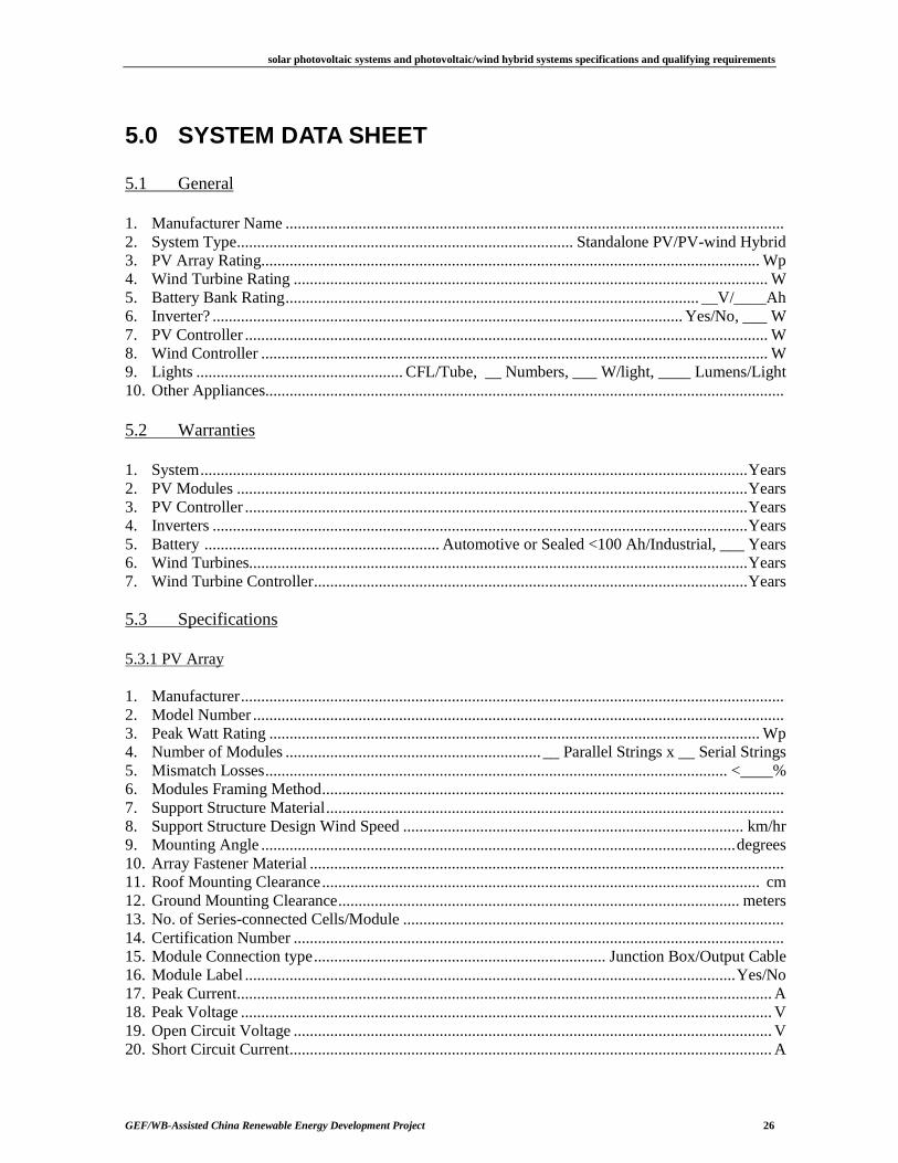
5.0 SYSTEM DATA SHEET 5.1 General
1. Manufacturer Name ........................................................................................................................... 2. System Type................................................................................... Standalone PV/PV-wind Hybrid 3. PV Array Rating........................................................................................................................... Wp 4. Wind Turbine Rating ..................................................................................................................... W 5. Battery Bank Rating...................................................................................................... __V/____Ah 6. Inverter? .................................................................................................................... Yes/No, ___ W 7. PV Controller ................................................................................................................................. W 8. Wind Controller ............................................................................................................................. W 9. Lights ................................................... CFL/Tube, __ Numbers, ___ W/light, ____ Lumens/Light 10. Other Appliances................................................................................................................................ 5.2 Warranties
1. System.......................................................................................................................................Years 2. PV Modules ..............................................................................................................................Years 3. PV Controller ............................................................................................................................Years 4. Inverters ....................................................................................................................................Years 5. Battery .......................................................... Automotive or Sealed <100 Ah/Industrial, ___ Years 6. Wind Turbines...........................................................................................................................Years 7. Wind Turbine Controller...........................................................................................................Years 5.3 Specifications
5.3.1 PV Array
1. Manufacturer...................................................................................................................................... 2. Model Number ................................................................................................................................... 3. Peak Watt Rating ......................................................................................................................... Wp 4. Number of Modules ............................................................... __ Parallel Strings x __ Serial Strings 5. Mismatch Losses.................................................................................................................. <____% 6. Modules Framing Method.................................................................................................................. 7. Support Structure Material................................................................................................................. 8. Support Structure Design Wind Speed .................................................................................... km/hr 9. Mounting Angle .....................................................................................................................degrees 10. Array Fastener Material ..................................................................................................................... 11. Roof Mounting Clearance............................................................................................................ cm 12. Ground Mounting Clearance................................................................................................... meters 13. No. of Series-connected Cells/Module .............................................................................................. 14. Certification Number ......................................................................................................................... 15. Module Connection type........................................................................ Junction Box/Output Cable 16. Module Label .........................................................................................................................Yes/No 17. Peak Current.................................................................................................................................... A 18. Peak Voltage ................................................................................................................................... V 19. Open Circuit Voltage ...................................................................................................................... V 20. Short Circuit Current....................................................................................................................... A
solar photovoltaic systems and photovoltaic/wind hybrid systems specifications and qualifying requirements
GEF/WB-Assisted China Renewable Energy Development Project 27
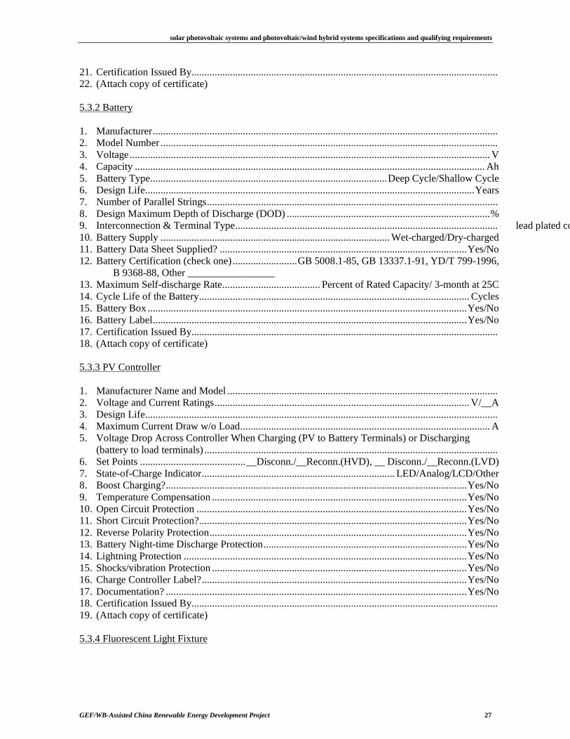
21. Certification Issued By....................................................................................................................... 22. (Attach copy of certificate) 5.3.2 Battery
1. Manufacturer...................................................................................................................................... 2. Model Number ................................................................................................................................... 3. Voltage............................................................................................................................................ V 4. Capacity ........................................................................................................................................ Ah 5. Battery Type............................................................................................Deep Cycle/Shallow Cycle 6. Design Life................................................................................................................................Years 7. Number of Parallel Strings................................................................................................................. 8. Design Maximum Depth of Discharge (DOD) ...............................................................................% 9. Interconnection & Terminal Type...................................................................................................... lead plated copper buss bars/flexible copper conductors/flag terminals10. Battery Supply ......................................................................................... Wet-charged/Dry-charged 11. Battery Data Sheet Supplied? ................................................................................................Yes/No 12. Battery Certification (check one).........................GB 5008.1-85, GB 13337.1-91, YD/T 799-1996,
B 9368-88, Other _________________ 13. Maximum Self-discharge Rate...................................... Percent of Rated Capacity/ 3-month at 25C 14. Cycle Life of the Battery......................................................................................................... Cycles 15. Battery Box ............................................................................................................................Yes/No 16. Battery Label..........................................................................................................................Yes/No 17. Certification Issued By....................................................................................................................... 18. (Attach copy of certificate) 5.3.3 PV Controller
1. Manufacturer Name and Model ......................................................................................................... 2. Voltage and Current Ratings................................................................................................... V/__A 3. Design Life......................................................................................................................................... 4. Maximum Current Draw w/o Load................................................................................................. A 5. Voltage Drop Across Controller When Charging (PV to Battery Terminals) or Discharging
(battery to load terminals) .................................................................................................................. 6. Set Points .........................................__Disconn./__Reconn.(HVD), __ Disconn./__Reconn.(LVD) 7. State-of-Charge Indicator........................................................................... LED/Analog/LCD/Other 8. Boost Charging?.....................................................................................................................Yes/No 9. Temperature Compensation ...................................................................................................Yes/No 10. Open Circuit Protection .........................................................................................................Yes/No 11. Short Circuit Protection?........................................................................................................Yes/No 12. Reverse Polarity Protection....................................................................................................Yes/No 13. Battery Night-time Discharge Protection...............................................................................Yes/No 14. Lightning Protection ..............................................................................................................Yes/No 15. Shocks/vibration Protection ...................................................................................................Yes/No 16. Charge Controller Label?.......................................................................................................Yes/No 17. Documentation? .....................................................................................................................Yes/No 18. Certification Issued By....................................................................................................................... 19. (Attach copy of certificate) 5.3.4 Fluorescent Light Fixture
solar photovoltaic systems and photovoltaic/wind hybrid systems specifications and qualifying requirements
GEF/WB-Assisted China Renewable Energy Development Project 28
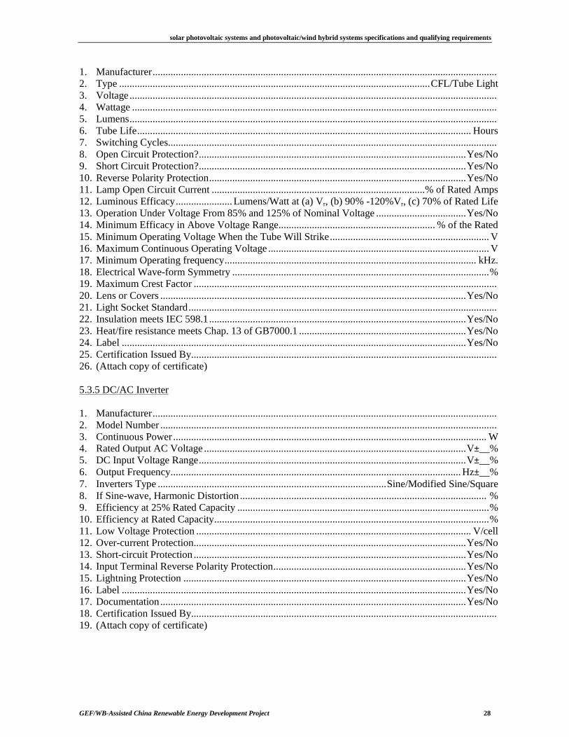
1. Manufacturer...................................................................................................................................... 2. Type .........................................................................................................................CFL/Tube Light 3. Voltage............................................................................................................................................... 4. Wattage .............................................................................................................................................. 5. Lumens............................................................................................................................................... 6. Tube Life.................................................................................................................................. Hours 7. Switching Cycles................................................................................................................................ 8. Open Circuit Protection?........................................................................................................Yes/No 9. Short Circuit Protection?........................................................................................................Yes/No 10. Reverse Polarity Protection....................................................................................................Yes/No 11. Lamp Open Circuit Current ...................................................................................% of Rated Amps 12. Luminous Efficacy...................... Lumens/Watt at (a) Vr, (b) 90% -120%Vr, (c) 70% of Rated Life 13. Operation Under Voltage From 85% and 125% of Nominal Voltage ...................................Yes/No 14. Minimum Efficacy in Above Voltage Range............................................................. % of the Rated 15. Minimum Operating Voltage When the Tube Will Strike.............................................................. V 16. Maximum Continuous Operating Voltage ...................................................................................... V 17. Minimum Operating frequency.................................................................................................. kHz. 18. Electrical Wave-form Symmetry ....................................................................................................% 19. Maximum Crest Factor ...................................................................................................................... 20. Lens or Covers .......................................................................................................................Yes/No 21. Light Socket Standard........................................................................................................................ 22. Insulation meets IEC 598.1....................................................................................................Yes/No 23. Heat/fire resistance meets Chap. 13 of GB7000.1 .................................................................Yes/No 24. Label ......................................................................................................................................Yes/No 25. Certification Issued By....................................................................................................................... 26. (Attach copy of certificate) 5.3.5 DC/AC Inverter
1. Manufacturer...................................................................................................................................... 2. Model Number ................................................................................................................................... 3. Continuous Power.......................................................................................................................... W 4. Rated Output AC Voltage ......................................................................................................V±__% 5. DC Input Voltage Range........................................................................................................V±__% 6. Output Frequency.................................................................................................................Hz±__% 7. Inverters Type .........................................................................................Sine/Modified Sine/Square 8. If Sine-wave, Harmonic Distortion................................................................................................ % 9. Efficiency at 25% Rated Capacity ..................................................................................................% 10. Efficiency at Rated Capacity...........................................................................................................% 11. Low Voltage Protection ........................................................................................................... V/cell 12. Over-current Protection..........................................................................................................Yes/No 13. Short-circuit Protection ..........................................................................................................Yes/No 14. Input Terminal Reverse Polarity Protection...........................................................................Yes/No 15. Lightning Protection ..............................................................................................................Yes/No 16. Label ......................................................................................................................................Yes/No 17. Documentation.......................................................................................................................Yes/No 18. Certification Issued By....................................................................................................................... 19. (Attach copy of certificate)
solar photovoltaic systems and photovoltaic/wind hybrid systems specifications and qualifying requirements
GEF/WB-Assisted China Renewable Energy Development Project 29
5.3.6 Wind Turbine
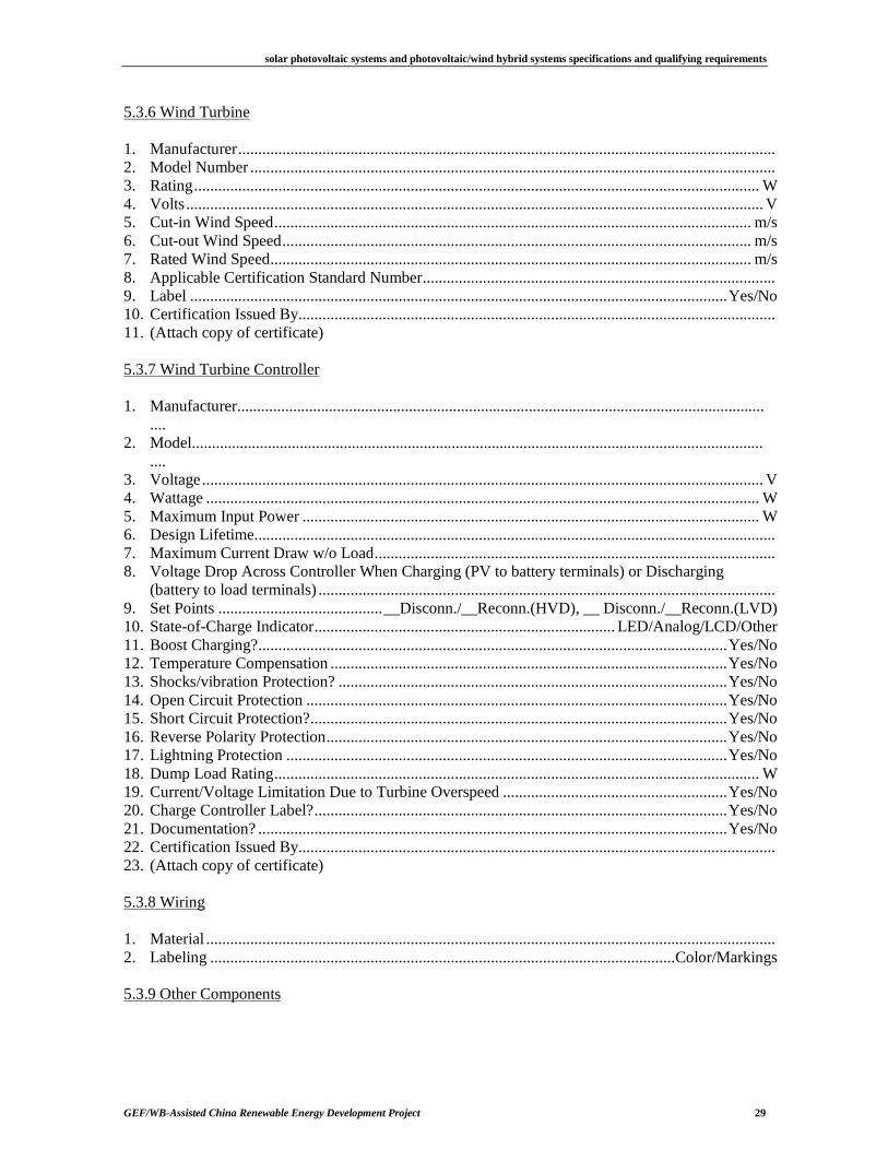
1. Manufacturer...................................................................................................................................... 2. Model Number ................................................................................................................................... 3. Rating............................................................................................................................................. W 4. Volts................................................................................................................................................ V 5. Cut-in Wind Speed....................................................................................................................... m/s 6. Cut-out Wind Speed..................................................................................................................... m/s 7. Rated Wind Speed........................................................................................................................ m/s 8. Applicable Certification Standard Number........................................................................................ 9. Label ......................................................................................................................................Yes/No 10. Certification Issued By....................................................................................................................... 11. (Attach copy of certificate) 5.3.7 Wind Turbine Controller
1. Manufacturer........................................................................................................................................
2. Model...................................................................................................................................................
3. Voltage............................................................................................................................................ V 4. Wattage .......................................................................................................................................... W 5. Maximum Input Power .................................................................................................................. W 6. Design Lifetime.................................................................................................................................. 7. Maximum Current Draw w/o Load.................................................................................................... 8. Voltage Drop Across Controller When Charging (PV to battery terminals) or Discharging
(battery to load terminals) .................................................................................................................. 9. Set Points .........................................__Disconn./__Reconn.(HVD), __ Disconn./__Reconn.(LVD) 10. State-of-Charge Indicator........................................................................... LED/Analog/LCD/Other 11. Boost Charging?.....................................................................................................................Yes/No 12. Temperature Compensation ...................................................................................................Yes/No 13. Shocks/vibration Protection? .................................................................................................Yes/No 14. Open Circuit Protection .........................................................................................................Yes/No 15. Short Circuit Protection?........................................................................................................Yes/No 16. Reverse Polarity Protection....................................................................................................Yes/No 17. Lightning Protection ..............................................................................................................Yes/No 18. Dump Load Rating......................................................................................................................... W 19. Current/Voltage Limitation Due to Turbine Overspeed ........................................................Yes/No 20. Charge Controller Label?.......................................................................................................Yes/No 21. Documentation? .....................................................................................................................Yes/No 22. Certification Issued By....................................................................................................................... 23. (Attach copy of certificate) 5.3.8 Wiring
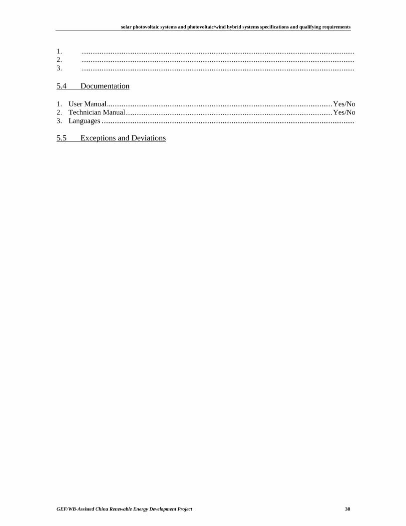
1. Material .............................................................................................................................................. 2. Labeling ....................................................................................................................Color/Markings 5.3.9 Other Components
solar photovoltaic systems and photovoltaic/wind hybrid systems specifications and qualifying requirements
GEF/WB-Assisted China Renewable Energy Development Project 30
1. ..................................................................................................................................................... 2. ..................................................................................................................................................... 3. ..................................................................................................................................................... 5.4 Documentation
1. User Manual...........................................................................................................................Yes/No 2. Technician Manual.................................................................................................................Yes/No 3. Languages .......................................................................................................................................... 5.5 Exceptions and Deviations