chilled water distribution
TRANSCRIPT

Department of Facilities Services
Chilled Water Distribution System
2013 Design Guidelines 1 | P a g e
Chilled Water Design Specifications Chilled Water Services
Department of Facilities Services
Chilled Water Distribution System
2013 Design Guidelines 2 | P a g e
Contents
Contents ......................................................................................................................................................................2 DESCRIPTION OF CHILLED WATER SYSTEM ..................................................................................................5
BUILDING SYSTEM - GENERALLY ...........................................................................................................6 PRIMARY/SECONDARY BUILDING BRIDGE SYSTEM – GENERALLY ..............................................7 BRIDGE RETURN TEMPERATURE CONTROL VALVE (TCV-A) DESIGN CRITERIA .......................8
UNDERGROUND CHILLED WATER DISTRIBUTION PIPING ...................................................................... 11 GENERAL .................................................................................................................................................... 11
Contractor Qualifications ........................................................................................................................ 11 Submittals (Copies to Chilled Water Engineer) ...................................................................................... 11 Record Documentation ........................................................................................................................... 12 Product Delivery, Storage and Handling ................................................................................................ 12 Pipe Materials ......................................................................................................................................... 12
VALVES ....................................................................................................................................................... 13 Butterfly Valves ...................................................................................................................................... 13 Valve Boxes ............................................................................................................................................ 13 Vent Valve Boxes ................................................................................................................................... 13 Tapping Sleeves ...................................................................................................................................... 14 Gate Valves (For Tapping Service Only)................................................................................................ 14
INSTALLATION .......................................................................................................................................... 14 CLEANING AND FLUSHING OF UNDERGROUND PIPING ................................................................. 15
Chilled Water (4” to 42”) ........................................................................................................................ 15 TESTING ...................................................................................................................................................... 16
CHILLED WATER BRIDGE ................................................................................................................................. 18 GENERAL .................................................................................................................................................... 18
Contractor Qualifications ........................................................................................................................ 18 Submittals (Copies to Chilled Water Engineer) ...................................................................................... 19
PRODUCT DELIVERY, STORAGE AND HANDLING ........................................................................... 19 VALVES ....................................................................................................................................................... 20
Butterfly Valves ...................................................................................................................................... 20 Butterfly Valve Installation ..................................................................................................................... 20 Chain Wheel Operators ........................................................................................................................... 21 Ball Valves .............................................................................................................................................. 21 Drains/ Vents .......................................................................................................................................... 21
INSTRUMENTATION ................................................................................................................................. 21 BUILDING CHILLED WATER PUMP ....................................................................................................... 22
Design Criteria ........................................................................................................................................ 22 Centrifugal Pumps................................................................................................................................... 23
MOTORS ...................................................................................................................................................... 23 Motor Grounding .................................................................................................................................... 24 Installation ............................................................................................................................................... 24 Pump Startup ........................................................................................................................................... 25
PIPE MATERIALS ....................................................................................................................................... 26 Flanges .................................................................................................................................................... 26 Flange Gaskets ........................................................................................................................................ 26 Bolting ..................................................................................................................................................... 26
PIPING INSTALLATION ............................................................................................................................ 26
Department of Facilities Services
Chilled Water Distribution System
2013 Design Guidelines 3 | P a g e
Welded Pipe Joints .................................................................................................................................. 27 Pipe Welding ........................................................................................................................................... 27
PIPE HANGERS AND SUPPORTS ............................................................................................................. 27 Hanger Rods (Metallic) ........................................................................................................................... 27 Bolts, Nuts, Studs and Washers .............................................................................................................. 28 Installation ............................................................................................................................................... 28 Hangers and Support Spacing ................................................................................................................. 28
PIPING SYSTEM PRESSURE TEST .......................................................................................................... 29 FLUSHING AND CHEMICAL CLEANING OF CHILLED WATER ABOVE GROUND PIPE
SYSTEMS .................................................................................................................................................. 29 Contractor Qualifications ........................................................................................................................ 29 Submittals ............................................................................................................................................... 29 Piping System Cleaner ............................................................................................................................ 30 Batch Chemical Feeder ........................................................................................................................... 30 Execution ................................................................................................................................................ 30 Flushing ................................................................................................................................................... 31 Cleaning .................................................................................................................................................. 31 Final Fill .................................................................................................................................................. 32
MECHANICAL INSULATION ................................................................................................................... 32 Product Delivery, Storage and Handling ................................................................................................ 32 Application .............................................................................................................................................. 32 Installation ............................................................................................................................................... 32
PIPE IDENTIFICATION .............................................................................................................................. 33 BRIDGE CONTROLS ............................................................................................................................................ 34
PRIMARY/SECONDARY BUILDING BRIDGE SYSTEM - DESCRIPTION OF OPERATION ............ 34 BRIDGE OPERATION FOR NON-ESSENTIAL AND ESSENTIAL LOADS ......................................... 34
Building and EMCS Interface ................................................................................................................. 34 Boost Coupled Mode .............................................................................................................................. 34 Decoupled Mode ..................................................................................................................................... 34 Coupled Mode ......................................................................................................................................... 35 Failure Mode ........................................................................................................................................... 35
INTERLOCKS AND METERING ............................................................................................................... 36 INSTRUMENT SPECIFICATIONS ............................................................................................................. 36
PANEL Bridge Panel/Control Cabinet ............................................................................................... 36 MC-1 Multi Loop Digital Controller ................................................................................................ 36 VFD Variable Frequency Drive ....................................................................................................... 37 TCV-A Return Temperature Control Valve ........................................................................................ 39 Alternate TCV-A Return Temperature Control Valve ........................................................................ 40 FV-B, FV-P Bypass Valves ................................................................................................................. 40 Alternate FV-B, FV-P Bypass Valves ................................................................................................ 41 FE/FT 1 Flow Element/Transmitter ..................................................................................................... 41 RTU, STU, RTB, STB Temperature Sensor Assembly ....................................................................... 41 Thermowell for RTD Sensor ................................................................................................................... 42 Thermometers ......................................................................................................................................... 42 Thermowell for Thermometer ................................................................................................................. 42 BE Bridge Enable Signal ....................................................................................................................... 42 PDT–1, 2 Differential Pressure Transmitter ...................................................................................... 42 Electrical Interlocks for Pump(s) ............................................................................................................ 43
Department of Facilities Services
Chilled Water Distribution System
2013 Design Guidelines 4 | P a g e
Instrumentation Cables ........................................................................................................................... 44 Pneumatic or Instrumentation Lines ....................................................................................................... 44 Conduit for Power and Instrumentation .................................................................................................. 44
APPENDIX ................................................................................................................................................................ 45 Appendix A Exposed Utility Temporary Support .......................................................................................... 45 Appendix B Typical Chilled Water Trench thru Paved Area ......................................................................... 46 Appendix C Typical Chilled Water Trench thru Landscaped Area ................................................................ 47 Appendix E Chilled Water Drain Assembly ................................................................................................... 49 Appendix F Chilled Water Air Vent Handhold .............................................................................................. 50 Appendix G Ductile Iron/Steel Pipe Transition At Wall Penetration ............................................................ 51 Appendix H Utility Piping Termination ......................................................................................................... 52 Appendix I Chiller Water Bridge Flow Diagram ............................................................................................ 53 Appendix J Pump Differential Pressure Gauge Detail .................................................................................. 54 Appendix K Requesting Outage for Chilled Water Service ......................................................................... 55 Appendix L Request for Chilled Water Outage ........................................................................................... 56
Department of Facilities Services
Chilled Water Distribution System
2013 Design Guidelines 5 | P a g e
DESCRIPTION OF CHILLED WATER SYSTEM
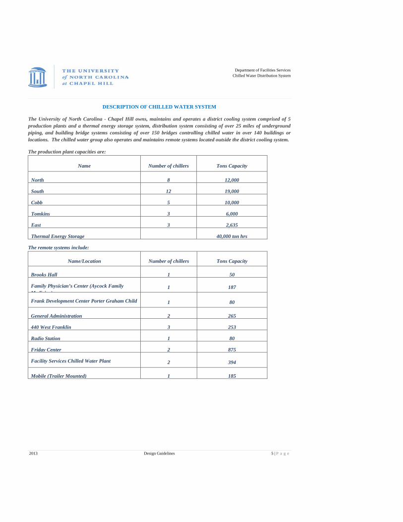
The University of North Carolina - Chapel Hill owns, maintains and operates a district cooling system comprised of 5 production plants and a thermal energy storage system, distribution system consisting of over 25 miles of underground piping, and building bridge systems consisting of over 150 bridges controlling chilled water in over 140 buildings or locations. The chilled water group also operates and maintains remote systems located outside the district cooling system.
The production plant capacities are:
Name Number of chillers Tons Capacity
North 8 12,000
South 12 19,000
Cobb 5 10,000
Tomkins 3 6,000
East 3 2,635
Thermal Energy Storage 40,000 ton hrs
The remote systems include:
Name/Location Number of chillers Tons Capacity
Brooks Hall 1 50
Family Physician’s Center (Aycock Family Medicine)
1 187
Frank Development Center Porter Graham Child 1 80
General Administration 2 265
440 West Franklin 3 253
Radio Station 1 80
Friday Center 2 875
Facility Services Chilled Water Plant 2 394
Mobile (Trailer Mounted) 1 185

Department of Facilities Services
Chilled Water Distribution System
2013 Design Guidelines 6 | P a g e
Chilled water is centrally produced and distributed throughout the campus, and this district cooling system shall be utilized wherever possible. The district cooling system is comprised of four major subsystems; the production system, the distribution system, the building bridge system, and the building cooling system. The Designer responsible for connecting to this system is primarily concerned with the last two subsystems. Designer shall provide all necessary information in specifications and drawing so that contractor may provide and install all instrumentation and control valves as described in this specification.
BUILDING SYSTEM - GENERALLY
The building system includes all chilled water piping in the building; the chilled water pump and all cooling coils, heat exchangers and other equipment using chilled water. The Designer must consider the following when designing the building chilled water systems.
The maximum allowable elevation of chilled water piping in the building is 565 feet above sea level and not less than 350 feet above sea level.
Designer must calculate chilled water static plus dynamic head for each project and determine if pressure limits of the chilled water system are exceeded. Buildings that require higher or lower elevations or higher heads must have plate and frame heat exchangers. Plate and frame heat exchangers must have the flow regulated on the primary (or supply) side of the heat exchanger by means of a properly sized control valve. The temperature sensor must be located on the secondary side of the heat exchanger in the leaving water line for controlling the chilled water supply temperature to the loads. The cooling coils and heat exchangers must be designed for variable flow, constant temperature differential. At design conditions these units must have a return temperature of at least 59 degrees F (60 degrees F if a heat exchanger is used) and not require a supply temperature of less than 45 degrees F. The return temperature during low load conditions shall not drop below 55 degrees F. The bridge enable shall be a hardwired 4 to 20MA signal (4=0% load and 20=100% load) from the Building Automation System to the Chilled Water Bridge controller. This signal represents the actual live total Chilled Water load in the building. For example, all the cooling control valve positions would be averaged together to base the output signal on. If there were three cooling control valves that represented 100% of the total cooling load and valve 1 was 25% open , valve 2 was 50% open and valve 3 was 75% open the average load would 50% and the bridge enable signal would be at 12 mA. If there is equipment with no feedback some other means of accounting for actual live load shall be factored in to the total load. All factors that are considered in the total load formula shall be bound out into a network output that can be read directly from the Building Automation System with our SCADA system via Modbus TCP. If necessary a device such as a fieldserver or other approved device may need to be installed to ensure that the most reliable and most direct means of data transmission is accomplished. The cooling coil tube velocity at design flow shall not be less than 4 FPS. Provide a leaving chilled water temperature sensor on all heat exchangers (cooling coils) over 10 tons rated cooling capacity. Chilled water from this system shall not be used for any application where the temperature of the heat exchanger surface in contact with the chilled water exceeds 75 degrees F. The building pump must be selected for the building system head and flow requirements. A variable volume pump is recommended, particularly in buildings with large cooling loads. The control valves and control systems on equipment served by the chilled water system must be capable of accurate low load control and close off across the building pump shutoff head. Use a separate bridge interface system for unusual or special cooling loads. A special load may require an elevated supply temperature, such as process equipment, or may be an essential load in a building with only non-essential AC loads, such as a computer room.

Department of Facilities Services
Chilled Water Distribution System
2013 Design Guidelines 7 | P a g e
PRIMARY/SECONDARY BUILDING BRIDGE SYSTEM – GENERALLY By definition a primary secondary bridge connection exists when the primary circuit (distribution mains) is connected to the secondary circuit (building system) by means of a low pressure loss pipe common to both circuits. The correct operation of the district cooling system is dependent on the design and operation of the primary/secondary bridge. Factors that affect the operation of the primary/secondary bridge are described below.
Flow head loss in distribution mains from production plant to point of connection. This value varies primarily with changes in distribution system load.
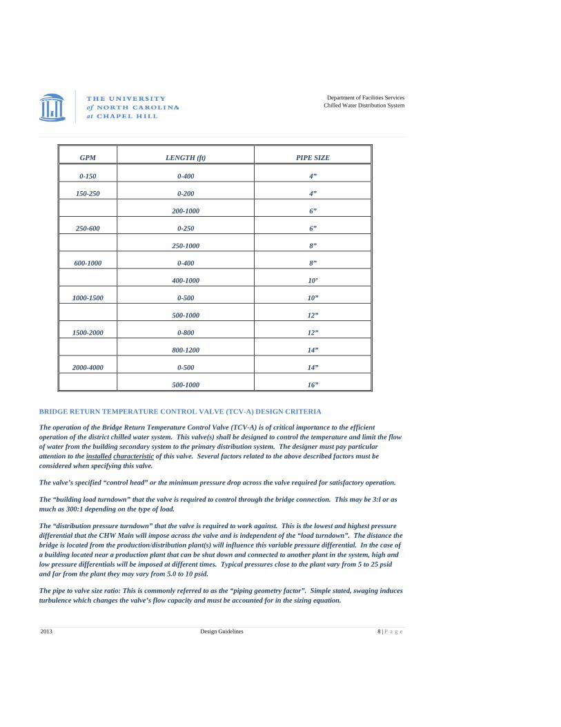
Flow head loss in branch lines between the bridge and the mains. This value varies primarily with changes in building system load. Generally, the branch piping should be designed with a velocity of 3 to 6 FPS depending on actual length. When determining the flow in the pipe, consider what future loads may be imposed upon it. Use the following schedule to determine branch piping size: (length = total equivalent feet of supply + return runs).
Department of Facilities Services
Chilled Water Distribution System
2013 Design Guidelines 8 | P a g e
GPM LENGTH (ft) PIPE SIZE
0-150 0-400 4”
150-250 0-200 4”
200-1000 6”
250-600 0-250 6”
250-1000 8”
600-1000 0-400 8”
400-1000 10’
1000-1500 0-500 10”
500-1000 12”
1500-2000 0-800 12”
800-1200 14”
2000-4000 0-500 14”
500-1000 16”
BRIDGE RETURN TEMPERATURE CONTROL VALVE (TCV-A) DESIGN CRITERIA
The operation of the Bridge Return Temperature Control Valve (TCV-A) is of critical importance to the efficient operation of the district chilled water system. This valve(s) shall be designed to control the temperature and limit the flow of water from the building secondary system to the primary distribution system. The designer must pay particular attention to the installed characteristic of this valve. Several factors related to the above described factors must be considered when specifying this valve.
The valve’s specified “control head” or the minimum pressure drop across the valve required for satisfactory operation.
The “building load turndown” that the valve is required to control through the bridge connection. This may be 3:l or as much as 300:1 depending on the type of load.
The “distribution pressure turndown” that the valve is required to work against. This is the lowest and highest pressure differential that the CHW Main will impose across the valve and is independent of the “load turndown”. The distance the bridge is located from the production/distribution plant(s) will influence this variable pressure differential. In the case of a building located near a production plant that can be shut down and connected to another plant in the system, high and low pressure differentials will be imposed at different times. Typical pressures close to the plant vary from 5 to 25 psid and far from the plant they may vary from 5.0 to 10 psid.
The pipe to valve size ratio: This is commonly referred to as the “piping geometry factor”. Simple stated, swaging induces turbulence which changes the valve’s flow capacity and must be accounted for in the sizing equation.

Department of Facilities Services
Chilled Water Distribution System
2013 Design Guidelines 9 | P a g e
The degree to which the valve will cavitate: Cavitation is a performance limit that fluid properties, pressure drop, and trim design impose upon valve operation.
The designer shall follow these specifications when specifying this valve:
The Bridge Return Temperature Control Valve (TCV-A) shall have a low sensitivity through the first part of its travel with increasing sensitivity as 100% of travel is approached. This equal percentage characteristic valve shall have an installed characteristic that approaches a linear response as valve travel changes with flow.
The designer will obtain from the Chilled Water Engineer (1) the minimum and maximum differential pressures in the mains at the branch connection to the building, (2) the distribution system static pressure in the mains at the branch connection to the building. These pressures must be assumed by the designer to be independent of building load. TCV-A must control flow from design down to 20% of the smallest unit load (coil, heat exchanger, or group of coils that constitute a minimum unit load) within the range of distribution system differential pressures specified by the Chilled Water Engineer. At the lowest building load and highest distribution system differential pressure, the valve must be at no less than 1% of its full range travel. At design flow and lowest mains differential, the valve must be at no more than 90% of its full range travel. If it is not possible to provide this type of response to changes in load with one valve, the designer may use parallel valves, sequentially controlled. Valve leakage at shut-off shall be no greater than 0.6% of design flow at 30 psid. The valve actuator shall be capable of valve shut-off against 50 psi differential.
The designer must specify a control valve for this application. The designer must include in the specifications a Bridge Performance Table and a Bridge Return Temperature Control Valve Table.
The bridge performance table shall have the following information:
Item 1: Average return temperature from all building loads at design conditions (designer must calculate value). This average return temperature will be the set point for TCV-A. A return temperature of 59° F or more is preferred for all building loads at design conditions (designer must calculate value). The supply temperature must not be less than 45° F. A separate interface must be provided if specific equipment needs a lower supply temperature.
Item 2: Total flow for all building loads at design conditions (designer must calculate value)
Item 3: Distribution system supply temperature (from Chilled Water Engineer)
Item 4: CHW flow in distribution system branch connections to building at design conditions (designer must calculate value)
Item 5: Pressure differential across the distribution mains at the point where the branch lines to the building are connected (from Chilled Water Engineer)
Item 6: Flow head loss due to piping in the branch lines between the distribution mains and the chilled water bridge bypass tees at design conditions (designer must calculate value)
Example: Bridge Performance Table
Building CHW design return temp 59 degrees F
Building CHW design supply temp 45 degrees F
Building design CHW flow 545 GPM
Distribution system supply temp 45 degrees F
Department of Facilities Services
Chilled Water Distribution System
2013 Design Guidelines 10 | P a g e
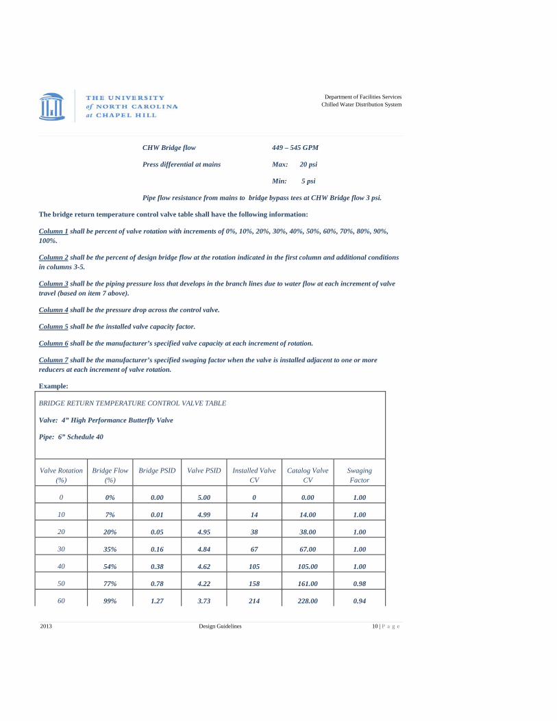
CHW Bridge flow 449 – 545 GPM
Press differential at mains Max: 20 psi
Min: 5 psi
Pipe flow resistance from mains to bridge bypass tees at CHW Bridge flow 3 psi.
The bridge return temperature control valve table shall have the following information:
Column 1 shall be percent of valve rotation with increments of 0%, 10%, 20%, 30%, 40%, 50%, 60%, 70%, 80%, 90%, 100%.
Column 2 shall be the percent of design bridge flow at the rotation indicated in the first column and additional conditions in columns 3-5.
Column 3 shall be the piping pressure loss that develops in the branch lines due to water flow at each increment of valve travel (based on item 7 above).
Column 4 shall be the pressure drop across the control valve.
Column 5 shall be the installed valve capacity factor.
Column 6 shall be the manufacturer’s specified valve capacity at each increment of rotation.
Column 7 shall be the manufacturer’s specified swaging factor when the valve is installed adjacent to one or more reducers at each increment of valve rotation.
Example:
BRIDGE RETURN TEMPERATURE CONTROL VALVE TABLE
Valve: 4” High Performance Butterfly Valve
Pipe: 6” Schedule 40
Valve Rotation (%)
Bridge Flow (%)
Bridge PSID Valve PSID Installed Valve CV
Catalog Valve CV
Swaging Factor
0 0% 0.00 5.00 0 0.00 1.00
10 7% 0.01 4.99 14 14.00 1.00
20 20% 0.05 4.95 38 38.00 1.00
30 35% 0.16 4.84 67 67.00 1.00
40 54% 0.38 4.62 105 105.00 1.00
50 77% 0.78 4.22 158 161.00 0.98
60 99% 1.27 3.73 214 228.00 0.94
Department of Facilities Services
Chilled Water Distribution System
2013 Design Guidelines 11 | P a g e
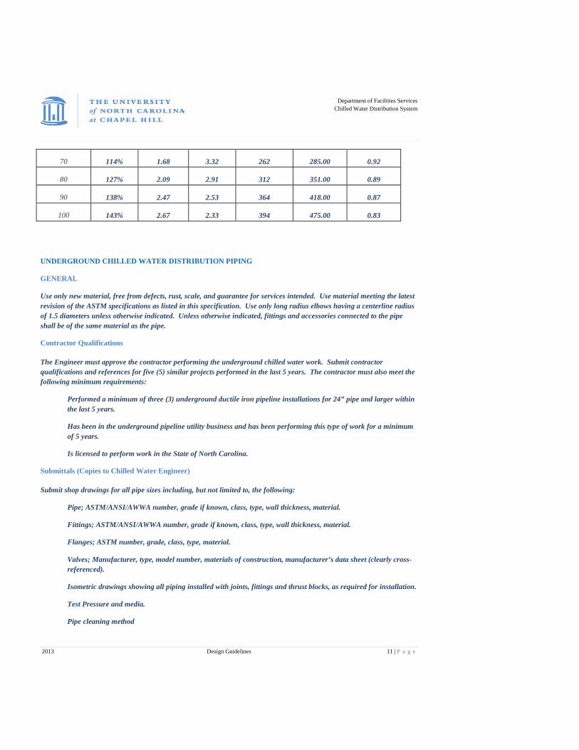
70 114% 1.68 3.32 262 285.00 0.92
80 127% 2.09 2.91 312 351.00 0.89
90 138% 2.47 2.53 364 418.00 0.87
100 143% 2.67 2.33 394 475.00 0.83
UNDERGROUND CHILLED WATER DISTRIBUTION PIPING
GENERAL
Use only new material, free from defects, rust, scale, and guarantee for services intended. Use material meeting the latest revision of the ASTM specifications as listed in this specification. Use only long radius elbows having a centerline radius of 1.5 diameters unless otherwise indicated. Unless otherwise indicated, fittings and accessories connected to the pipe shall be of the same material as the pipe.
Contractor Qualifications
The Engineer must approve the contractor performing the underground chilled water work. Submit contractor qualifications and references for five (5) similar projects performed in the last 5 years. The contractor must also meet the following minimum requirements:
Performed a minimum of three (3) underground ductile iron pipeline installations for 24” pipe and larger within the last 5 years.
Has been in the underground pipeline utility business and has been performing this type of work for a minimum of 5 years.
Is licensed to perform work in the State of North Carolina.
Submittals (Copies to Chilled Water Engineer)
Submit shop drawings for all pipe sizes including, but not limited to, the following:
Pipe; ASTM/ANSI/AWWA number, grade if known, class, type, wall thickness, material.
Fittings; ASTM/ANSI/AWWA number, grade if known, class, type, wall thickness, material.
Flanges; ASTM number, grade, class, type, material.
Valves; Manufacturer, type, model number, materials of construction, manufacturer’s data sheet (clearly cross-referenced).
Isometric drawings showing all piping installed with joints, fittings and thrust blocks, as required for installation.
Test Pressure and media.
Pipe cleaning method
Department of Facilities Services
Chilled Water Distribution System
2013 Design Guidelines 12 | P a g e
Record Documentation
Prior to acceptance of installation and use, contractor shall deliver two (2) copies of survey quality as built construction drawings for UNC to review and approve. Drawing to include GIS survey of points including change of directions, valves & tie in locations. A photograph library of the installation prior to backfilling is required. Photographs should include changes in direction, thrust block installation, pipe restraints and other pertinent information. The photographs must include background landmarks to verify location, orientation and physical attributes of the installation.
Product Delivery, Storage and Handling
Furnish all pipes with plastic end-caps/plugs on each end of pipe. Maintain end-caps/plugs through shipping, storage and handling to prevent pipe end damage and eliminate dirt and construction debris from accumulating inside the pipe.
Pipe Materials
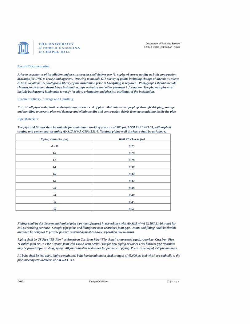
The pipe and fittings shall be suitable for a minimum working pressure of 300 psi, ANSI C151/A21.51, with asphalt coating and cement mortar lining ANSI/AWWA C104/A21.4. Nominal piping wall thickness shall be as follows:
Piping Diameter (in) Wall Thickness (in)
4 – 8 0.25
10 0.26
12 0.28
14 0.30
16 0.32
18 0.34
20 0.36
24 0.40
30 0.45
36 0.51
Fittings shall be ductile iron mechanical joint type manufactured in accordance with ANSI/AWWA C110/A21-10, rated for 250 psi working pressure. Straight pipe joints and fittings are to be restrained joint-type. Joints and fittings shall be flexible and shall be designed to provide positive restraint against end-wise separation due to thrust.
Piping shall be US Pipe “TR-Flex” or American Cast Iron Pipe “Flex Ring” or approved equal. American Cast Iron Pipe “Fastite” joint or US Pipe “Tyton” joint with EBBA Iron Series 1100 for new piping or Series 1700 harness type restraints may be provided for existing piping. All joints must be restrained for permanent piping. Pressure rating of 250 psi minimum.
All bolts shall be low alloy, high strength steel bolts having minimum yield strength of 45,000 psi and which are cathodic to the pipe, meeting requirements of AWWA C111.

Department of Facilities Services
Chilled Water Distribution System
2013 Design Guidelines 13 | P a g e
Restrained type joint fittings shall be equal to EBBA Iron Series 1100 Megalug restraint systems for mechanical joint ductile iron piping, fittings and valves. Series 1100 solid ring restraints shall have a rated working pressure of 350 psi up to 16” pipe and 250 psi for 18” to 36” pipe. Series 1100 split ring restrains shall have a rated working pressure of 300 psi up to 16” and 200 psi for 18” to 36” pipe. Gasket material shall be SBR.
When piping is installed and to be left unattended or overnight, installation of non-pressure pipe plugs is required, or permanent plugs must be installed. Non-pressure plugs shall be equal to Taylor Made Plastics Bell End or Spigot End Plugs. The plugs shall be polyethylene with gaskets designed to keep pipes clean.
VALVES
Butterfly Valves
Valves to be designed for direct buried application and shall conform to latest revision of AWWA C504 in addition to the requirements listed below.
Valves shall be rated for AWWA C504 Class 250B, 250 psi non-shock working pressure-minimum. Valves to be bubble-tight at the rated pressure in either direction, and shall be suitable for throttling service and operation after long periods of inactivity. Valves to be hydrostatic and leak tested in accordance with AWWA C504.
Ductile iron body ASTM A536, restrained mechanical joint (AWWA C111/ANSI 21.11) ends. Valve shall be furnished complete with all required MJ joint accessories (bolts, nuts, gaskets and glands).
Valve discs shall be constructed of cast iron ASTM A126, Class B, or ductile iron ASTM A536. Disc shall have ASTM A276-Type 316 continuous stainless steel seating edge to mate with valve seat.
Valve shaft to be corrosion resistant, ASTM A276-Type 304; ASTM A276-Type 316; ASTM A564 Grade 65-45-12 or approved equal.
Resilient seat shall be natural rubber (BUNA-N). Seat shall be bonded or mechanically retained in the valve body only. The seat shall be capable of mechanical adjustment in the field and/or in the field replacement.
Valve assembly shall be furnished with a non-adjustable, factory set, thrust bearing designed to center the valve disc at all times. Shaft bearings shall be contained in the integral hubs of the valve body and shall be self-lubricated sleeve type and shall be sealed in place with self-adjusting packing.
Valves to be complete with grease packed buried service gear operator in compliance with latest revision of AWWA C504. Actuator shall have adjustable open and closed mechanical position stops that can withstand input torque of 450 ft-lbs. Operator shall include shaft extensions to within one foot of finished grade, centering disk(s) located on shaft, and all required soil pipes. Refer to drawings for length of shaft extensions and soil pipes.
Manufacturers: DeZurik , Pratt, or approved equal.
Valve Boxes
Valve boxes shall be 2 – piece cast iron, screw type, 5.25” shaft with stay-put heavy duty traffic weight lid marked “CHILLED WATER”. Boxes shall be equal to figure UTL 273, as manufactured by Charlotte Pipe and Foundry Co., Dewey Brothers or Tyler.
Valve boxes to be coated with coal tar for direct buried service application.
Vent Valve Boxes

Department of Facilities Services
Chilled Water Distribution System
2013 Design Guidelines 14 | P a g e
Vent valve boxes shall be 2-piece cast iron, 12 inch diameter box with a cover with a highway H20 rating. Boxes shall be located directly above the installed corporation stop. Mark cover as “Chilled Water”.
Tapping Sleeves
NOTE: Tapping sleeves can be used if approved by Chilled Water Manager.
Tapping sleeves shall be manufactured from Type 304 stainless steel plate with a stainless steel ring flange, compatible with ANSI Class 125 and 150 bolt circles. The body and outlet shall be chemically passivated after welding for maximum corrosion resistance. The side bars shall be heavy gauge stainless steel. Trackhead bolts shall be 304 stainless steel with heavy nuts with UNC thread. Nuts shall be coated to prevent galling. Tapping sleeve shall be Romac STS420, no exceptions allowed.
Flange shall be stainless steel class “D” plate flange, with proper recessing for tapping valves. Flange will accommodate tapping flanges per MSS SP-60.
Gaskets for the flange and outlet sealing gaskets shall be Styrene Butadiene Rubber (SBR) compounded for water and sewer in accordance with ASTM D2000.
Gate Valves (For Tapping Service Only)
Conform to latest version of the AWWA Standard C-509 for resilient seated gate valves. There shall be a non-rising stem. The stem shall be cast bronze. The stem stuffing box shall be the O-ring seal type with two rings located above the thrust collar. The valve shall have a smooth full diameter waterway with no recesses.
The valve body and wedge shall be cast iron or ductile iron and shall be coated inside and outside with epoxy. The epoxy coating must meet or exceed AWWA C-550. The valve shall be designed for a pressure rating of 200 psig and shall be hydrostatically tested at 400 psig. The wedge must be completely encapsulated with rubber. Valves shall be furnished with ground level indicators and extension stems.
Manufacturers: U S Pipe, Clow or approved equal.
INSTALLATION
DESIGN & INSTALLATION NOTE: If installation is to connect to existing piping and that piping is unrestrained, a thrust block must be designed and installed before excavation can begin to the installation of the new piping. See details for design requirements of thrust block.
When digging within 10 feet of chilled water piping and the piping is unrestrained:
Locate chilled water pipes.
If the centerline of the chilled water lines and the proposed utility are less than 8 feet apart and any part of the proposed utility is below the top of the chilled water pipe, install the utility as follows:
Locate both chilled water lines and the proposed utility, excavate joints one at a time and install split ring megalug restraints.
When the restraints have been installed, backfill and compact to 90%. Backfill to original grade.
Install proposed utility section and proceed to next unrestrained joint. If required, all of the restraint work can be completed before any of the proposed work is started.
Department of Facilities Services
Chilled Water Distribution System
2013 Design Guidelines 15 | P a g e
All pipe, valves and fittings shall be installed as indicated on the drawings and according to the manufacturers’ instructions and UNC Chilled Water details.
Provide vents at all high points of pipe sections. Coordinate location of drains with Chilled Water Engineer. Whenever possible the drain lines shall be run to the sanitary sewer system. If sanitary sewer is not available provide a pump out manhole (see Standard Details).
Provide a stabilizing concrete pad around all valve boxes (see Standard Details). Do not locate valve boxes in parking spaces or in other inaccessible locations unless approved by Chilled Water Engineer.
Provide a chilled water monument marker at each change of direction, branch, and 200 feet of straight run of pipe. The marker shall consist of a chilled water marker (provided by Chilled Water). The marker shall be located midway between the two chilled water pipes. Physical location of the markers will be done using as-built drawings supplied by contractor and coordinated with Chilled Water.
Install locate wire on top of pipe with an anode bag at the connection to the main piping. The wire shall be taped to the pipe at 10 foot intervals and run full length to the piping. At the building the wire shall be brought to the surface and terminate in a locate wire box. The box shall consist of an electrical handybox with hinged opening and an 18” length of ¾” rigid conduit extended out the bottom of the box. All joints in the locate wire shall be done with Nicotap fittings and shrink wrap.
INSTALLATION NOTE: All items, including wire, needed to install the locate wire shall be supplied by UNC. Use extreme caution to keep the wire on top of pipe and not to damage the wire during backfill operations.
Install chilled water marking tape 2 feet above each pipe installed.
CLEANING AND FLUSHING OF UNDERGROUND PIPING
Chilled Water (4” to 42”)
Contractor shall visually inspect internal portion of each length of pipe during installation. Remove all dirt and foreign matter prior to installing additional lengths.
After each major section of piping has been installed, it shall be cleaned and flushed utilizing a high-pressure water “hydro-jet” process. The hydro-jet process involves passing a high pressure, high volume spray type cleaning head through the piping. The head is inserted in each section of piping and activated with full water pressure and flow. Through hydraulic force from directional spray nozzles the head propels itself forward up the pipe section. Once the head reaches the end of the pipe section it is retracted while maintaining maximum water pressure and flow. The length of the piping section shall be determined ahead of time so that the proper amount of travel can be tracked with calibrated markings on the spray head feed water hose or a meter on the hose reel. While traveling through the piping the pressurized water spray knocks debris loose and carries it back to the open end of the piping where it is collected and removed from the system. For each section of piping the process shall be performed a minimum of two times and may need to be repeated until the water exiting the end of the pipe is clear and free of debris as determined by the Owner/Engineer.
The hydro-jet equipment utilized shall be capable of providing a minimum of 50 GPM at 2000 PSI. All cleaning and flushing shall be performed so that all debris will be pulled or flushed downhill. All cleaning and flushing shall be initiated from all low points in the system and shall terminate at the nearest adjacent high point in the system.
Department of Facilities Services
Chilled Water Distribution System
2013 Design Guidelines 16 | P a g e
Coordinate the limitations and requirements of hydro-jet process with the flushing subcontractor such that the piping is installed in a sequence and manner that allows every section of the new pipeline to be cleaned and flushed. Limitations may include maximum length of the pipe section, maximum number and/or degree of bends in the pipe section, maximum slope of the pipe section, equipment and excavation access requirements, and the minimum size of the openings required in the piping to allow for insertion and retraction of the cleaning head.
Contractor shall provide access at all low points through valves, tees, flanges, etc. to facilitate the cleaning and flushing process. If temporary fittings or piping is required it shall be provided by the Contractor and removed by the Contractor after successful cleaning.
After flushing and cleaning is completed, contractor shall provide necessary pipe and fittings required to complete the piping system. Each cleaned section of piping shall be capped and protected to keep mud, debris, water, etc. from entering the piping. If a piping section is left open or unprotected, or is contaminated, it shall be re-cleaned prior to being filled and activated at no cost to the Owner.
Contractor shall provide all water for flushing and testing. Coordinate rental of fire hydrant meters with local Fire Department(s), or the University as required.
Contractor shall provide all temporary piping from water source to piping system and shall provide means for conducting cleaning water from underground piping system to the appropriate sewer; i.e. pumps, piping, hoses, tanks, etc. Contractor to remove all temporary piping, pumps, hoses, etc. from site immediately after flushing has been completed.
TESTING
The chilled water piping shall be leakage rate tested. Leakage rate test shall be conducted at the same time as the hydrostatic pressure test. Leakage rate is defined as the quantity of water that must be supplied into the respective underground piping system to maintain the pressure within 5 psig of the specified hydrostatic test pressure after air in piping system has been removed and piping system has been filled with water. The test pressure shall be 180 psig at the highest point of the piping being tested.
The pressure tests shall be sustained for not less than four hours and or long as the Chilled Water Engineer/Representative requires assuring that:
The scale of the test gauge must be a minimum of 50 psi higher than the anticipated test pressure and the incremental reading of the gauge is 2 psi.
No air pockets are in the line.
No broken pipe or defective materials are in the line.
No leaking joints have been made.
Before applying the specified test pressure, all air shall be expelled from the pipe. If outlets are not available at high places, the Contractor shall make the necessary taps at points of highest elevations before the test is made. After the test is completed, corporation cocks shall be installed at these points and marked by the installation of a valve box.
Tests may be made of isolated portions of such piping as will facilitate general progress of the installation. Any revisions made in the piping systems will subsequently necessitate re-testing of such affected portions of the piping systems.
Any defective material or defects in workmanship that develop during the tests shall be remedied and the subject piping shall be re-tested.
Determine the maximum allowable amount of leakage by the following formula:
Department of Facilities Services
Chilled Water Distribution System
2013 Design Guidelines 17 | P a g e
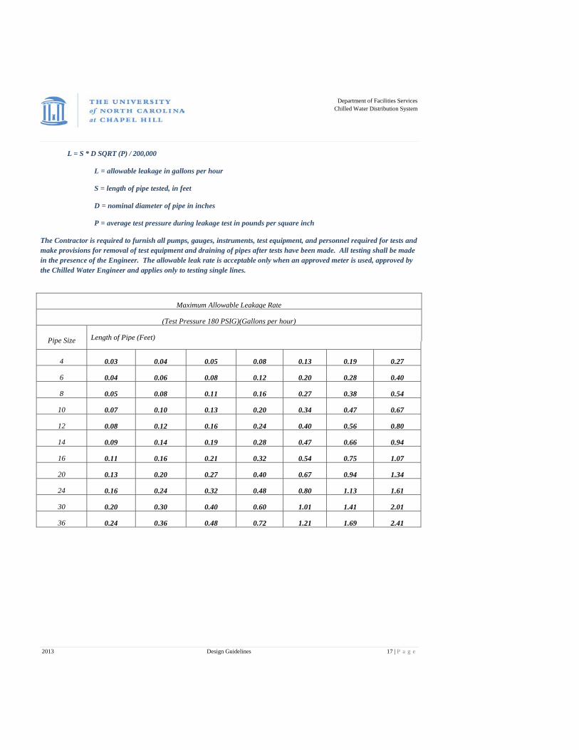
L = S * D SQRT (P) / 200,000
L = allowable leakage in gallons per hour
S = length of pipe tested, in feet
D = nominal diameter of pipe in inches
P = average test pressure during leakage test in pounds per square inch
The Contractor is required to furnish all pumps, gauges, instruments, test equipment, and personnel required for tests and make provisions for removal of test equipment and draining of pipes after tests have been made. All testing shall be made in the presence of the Engineer. The allowable leak rate is acceptable only when an approved meter is used, approved by the Chilled Water Engineer and applies only to testing single lines.
Maximum Allowable Leakage Rate
(Test Pressure 180 PSIG)(Gallons per hour)
Pipe Size Length of Pipe (Feet)
4 0.03 0.04 0.05 0.08 0.13 0.19 0.27
6 0.04 0.06 0.08 0.12 0.20 0.28 0.40
8 0.05 0.08 0.11 0.16 0.27 0.38 0.54
10 0.07 0.10 0.13 0.20 0.34 0.47 0.67
12 0.08 0.12 0.16 0.24 0.40 0.56 0.80
14 0.09 0.14 0.19 0.28 0.47 0.66 0.94
16 0.11 0.16 0.21 0.32 0.54 0.75 1.07
20 0.13 0.20 0.27 0.40 0.67 0.94 1.34
24 0.16 0.24 0.32 0.48 0.80 1.13 1.61
30 0.20 0.30 0.40 0.60 1.01 1.41 2.01
36 0.24 0.36 0.48 0.72 1.21 1.69 2.41

Department of Facilities Services
Chilled Water Distribution System
2013 Design Guidelines 18 | P a g e
CHILLED WATER BRIDGE
GENERAL
A specification of an item in this or any other sections shall not relieve Contractor from providing all items, articles, materials, operations, methods, labor, equipment and incidentals necessary for a complete and functional system.
Where size for a pipe segment is not indicated, the pipe segment size shall be equal to the largest pipe segment to which it is connected. Transition to smaller size shall occur on the side of fitting where smaller size is indicated.
All pipe, valves, fittings and pumps shall be installed as indicated on the drawings and according to the manufacturer’s instructions and installation drawings. All welding shall be performed to meet ASTM B31.1 unless noted by designer as otherwise.
General Locations and Arrangements Drawings (plans, details, schematics, and diagrams) indicate the general location and arrangement of the piping systems. Location and arrangement of piping layout shall take into consideration pipe sizing, friction loss, pump sizing, maintenance accessibility and other design considerations. So far as possible, install piping as indicated.
Design Note: Design of the bridge piping shall place bridge inside mechanical room and install bridge controller cabinet, all instruments, valves and meter between building isolation and utility isolation valves, excluding the end of line differential pressure transmitter.
Contractor Qualifications
The Engineer must approve the contractor performing building piping work. Submit contractor qualifications and references for five (5) similar projects performed in the last 5 years. The contractor must also meet the following minimum requirements:
Performed a minimum of three (3) institutional building piping installations within the last 5 years.
Has been in the institutional building piping business and has been performing this type of work for a minimum of 5 years.
Is licensed to perform work in the State of North Carolina.

Department of Facilities Services
Chilled Water Distribution System
2013 Design Guidelines 19 | P a g e
Submittals (Copies to Chilled Water Engineer)
Submit shop drawings for all pipe sizes including, but not limited to, the following:
Pipe; ASTM/ANSI number, grade if known, class, type, wall thickness, material.
Fittings; ASTM/ANSI number, grade if known, class, type, wall thickness, material.
Flanges; ASTM number, grade, class, type, material.
Isometric drawings showing routing, sensor location, valve location and hanger locations.
Test Pressure and media.
Pipe cleaning method.
Valves; manufacturer cut sheets, size, materials, actuator size, pressure rating.
Pumps; manufacturer cut sheets, pump curves, including design capacity and head, motor cut sheets, pump base design, pump installation requirements, pump manufacturers alignment specifications, flexible coupling design and cut sheet.
Variable speed drive; manufacturer cut sheets, size, installation requirements.
Welder certifications.
Thermowells; material, size.
Thermometer; manufacturer cut sheet, size, range.
Pressure Transmitter; type, manufacturer, manufacturer’s cut sheet, size, range.
PRODUCT DELIVERY, STORAGE AND HANDLING
Before shipping, all carbon steel piping shall be free of rust and scale, and furnished with plastic end caps/plugs on each end of pipe. Protect flanges, fittings, and specialties from moisture and dirt by inside storage and enclosure, or by packing with durable waterproof wrapping.
Store and handle all materials in accordance with Manufacturer's recommendations to prevent their deterioration and damage. Store all materials in the original containers or bundles with labels informing about manufacturer, product name, and any potential damage.
Where possible, store all materials inside and protect from weather. Where necessary to store outside, elevate well above grade and enclose with durable, waterproof wrapping. When stored inside, do not exceed the structural capacity of the floor.

Department of Facilities Services
Chilled Water Distribution System
2013 Design Guidelines 20 | P a g e
VALVES
Butterfly Valves
For Control Valves see Chilled Water Control Valves Specifications, starting on page 45. For the Chilled Water Bridge System, other than Control Valves, provide high performance butterfly valves.
The valve shall have a lugged wafer style body of carbon steel or ductile iron rated for ANSI class 150 service. The seat material shall be fluoropolymer based blend with no fillers or PTFE filled. Disk and shaft shall be 316 Stainless steel construction. Disk to shaft connection shall be non-shear tangential pinning. Disk shall be offset from shaft centerline. The valve shall have upper and lower shaft bushing/bearings of a 316 stainless steel carrier and PTFE liner. Shaft seal shall be multiple rings of V-flex style PTFE packing with 316 stainless steel packing ring.
Valves shall be full lug type permitting removal of downstream piping while using valve for system shut-off. Bi-directional dead end pressure rating to be minimum 150 psig with no downstream flange/piping attached.
Standard applications shall use 10-position lever operators for valve sizes 6” and smaller, gear operator for larger sizes.
Manufacturers: Jamesbury, or approved equal.
Butterfly Valve Installation
Install valves as shown on plans, details and according to valve manufacturer's installation recommendations.
Valves may be used to facilitate the fit-up of weld neck flanges, but the valve must be removed before the flanges are welded. During fit-up, metal pancakes or solid pieces of gasket material shall be used to ensure that valve is not damaged from sparks or spatter.
Valves with gear operators or actuators are to be installed with stems at or above centerline wherever possible, but in no case with the stems straight down. Valves with actuators and position indicators shall be installed so that the indicator is visible from the floor. Any valve installed with reducers nearby must have appropriate spacing to remove any bolt without pipe disassembly.
Before tightening flange bolts, adjust the disc of the valve to the full open position. Tighten bolts to specification in a criss-cross pattern. After tightening, rotate disc to closed position to assure proper operation.
After piping systems have been pressure tested and put into service, but before final adjusting and balancing, inspect valves for leaks. Adjust, replace packing or replace valves to stop leaks.
Department of Facilities Services
Chilled Water Distribution System
2013 Design Guidelines 21 | P a g e
Chain Wheel Operators
Provide chain operators for manually operated valves 6" and larger, located more than 8 ft. above equipment room floor.
Cast iron or ductile iron adjustable sprocket rims and chain guides. Use galvanized or brass chain and chain closure links to form continuous loop of chain at each operator.
Ball Valves
Ball valves for use in chilled water system to be rated for 250 psig at 100°F. Provide valve neck extensions with sufficient length to allow for insulation.
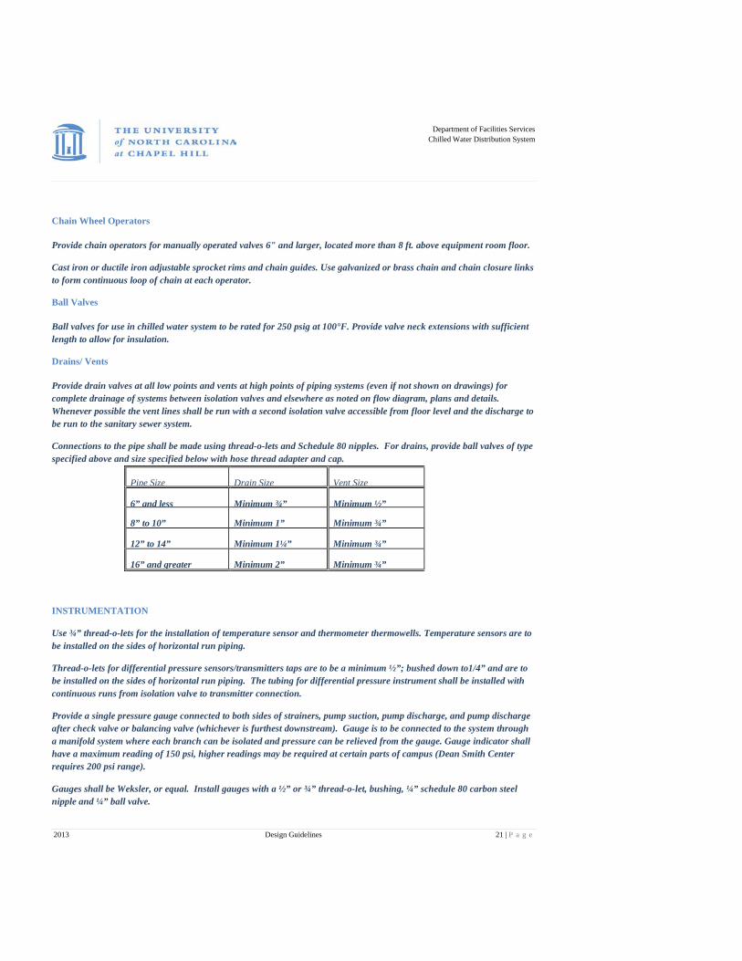
Drains/ Vents
Provide drain valves at all low points and vents at high points of piping systems (even if not shown on drawings) for complete drainage of systems between isolation valves and elsewhere as noted on flow diagram, plans and details. Whenever possible the vent lines shall be run with a second isolation valve accessible from floor level and the discharge to be run to the sanitary sewer system.
Connections to the pipe shall be made using thread-o-lets and Schedule 80 nipples. For drains, provide ball valves of type specified above and size specified below with hose thread adapter and cap.
Pipe Size Drain Size Vent Size
6” and less Minimum ¾” Minimum ½”
8” to 10” Minimum 1” Minimum ¾”
12” to 14” Minimum 1¼” Minimum ¾”
16” and greater Minimum 2” Minimum ¾”
INSTRUMENTATION
Use ¾” thread-o-lets for the installation of temperature sensor and thermometer thermowells. Temperature sensors are to be installed on the sides of horizontal run piping.
Thread-o-lets for differential pressure sensors/transmitters taps are to be a minimum ½”; bushed down to1/4” and are to be installed on the sides of horizontal run piping. The tubing for differential pressure instrument shall be installed with continuous runs from isolation valve to transmitter connection.
Provide a single pressure gauge connected to both sides of strainers, pump suction, pump discharge, and pump discharge after check valve or balancing valve (whichever is furthest downstream). Gauge is to be connected to the system through a manifold system where each branch can be isolated and pressure can be relieved from the gauge. Gauge indicator shall have a maximum reading of 150 psi, higher readings may be required at certain parts of campus (Dean Smith Center requires 200 psi range).
Gauges shall be Weksler, or equal. Install gauges with a ½” or ¾” thread-o-let, bushing, ¼” schedule 80 carbon steel nipple and ¼” ball valve.
Department of Facilities Services
Chilled Water Distribution System
2013 Design Guidelines 22 | P a g e
Compressed air tubing must be copper or stainless steel from isolation valve to instrument or control valve and shall be run in a manner that will not promote trapping of water. Each end-user of compressed air shall have individual isolation valves and control valves with positioners which shall have filters and separators with have fully automatic drains. Compressed air lines must be sized for all components using their delivery rates. Branch lines shall be 3/8 inch minimum with no more than 5 feet from the isolation valve to the pressure set or solenoid. If more than two components are being served main line size should be run to the last component served.
Install four thermometers; four temperature sensors; flow meter; pressure differential transmitter with local digital readout and remote pressure differential transmitter as per flow diagrams between the four bridge isolation valves.
Install V-Cone flow meter, supplied by the University, as per flow diagram. The preferred meter installation is in horizontal pipe runs. For a meter being installed in same size bridge piping there shall be a minimum of 5 pipe diameters before the meter and three pipe diameters after the meter. If installing smaller meter than the bridge piping, have four pipe diameters between the meter flanges and the reducers on both sides of the meter, the same requirement shall be used for any fittings used adjacent to the meter. For horizontal installation, this meter must be installed in either the three o’clock or nine o’clock positions or a maximum of 45 degrees below these positions. If the meter must be installed in a vertical run, the flow must come from under the meter so that the cone will not entrap air. The meter must not be installed downstream from a control valve. The meter must not be installed in the highest point of a pipe system.
BUILDING CHILLED WATER PUMP
Design Criteria
Pump sizes, capacities, pressures and operating characteristics shall be as scheduled. Where pumps are indicated for parallel operation, each pump must be capable of delivering at least 80% of the building’s full load flow.
Pumps shall have a minimum clearance of 24" on sides and ends of pumps and motors to allow access for service and repair. Pumps shall have isolation valves to allow removal of pumps for repair. Pumps shall have bleed valves and gauge ports at accessible locations. All pumps shall be serviceable without removing the volute from piping connections. Pumps shall meet or exceed operating efficiencies scheduled.
Furnish pumps complete with premium efficiency inverter-duty motors, drive assemblies, coupling guard where required and accessories as specified. Select motor with sufficient horsepower rating for non-overloading operation over entire pump curve.
Comment [DNM1]:

Department of Facilities Services
Chilled Water Distribution System
2013 Design Guidelines 23 | P a g e
Furnish each pump and motor with name plate giving manufacturer’s name, serial number of pump, capacity in GPM and head in feet at design condition, horsepower, voltage, frequency, speed, and full load current. Test all pumps hydraulically at 150% of rated pressure, clean and paint before shipment. Manufacturer shall certify all pump ratings and contractor will supply performance information as part of the submittal.
All pumps shall operate without objectionable noise or vibration with maximum noise level of 85 dBA.
Furnish one set of seals and bearings for each new pump to Owner.
Centrifugal Pumps
Pumps to be base mounted and flexible coupled with working pressure of 175 psi and operating temperature of 250 degrees F intermittent. Efficiency of the pump shall be greater than 85%. Pump design must allow for servicing without disturbing piping, motor or requiring shaft realignment. Pumps shall be designed and tested to Hydraulic Institute Standards.
Casings shall be cast iron having a minimum tensile strength of 35,000 psi. Removal of impeller or rotating assembly shall be accomplished without disconnecting suction and discharge piping. Casings to have tapped and plugged openings for vent, drain, and suction and discharge gauge connections.
Impellers to be made of cast bronze, hydraulically and dynamically balanced, keyed and locked to pump shafts with replaceable shaft sleeves. Rotating elements shall be mounted in heavy-duty ball bearings (greasable preferred) and shall be equipped with water slingers on the side next to pump glands.
Chilled water pumps to be furnished with single inside, unbalanced mechanical seals with carbon rotating faces, ceramic stationary seats, Buna-N elastomer and 316 SS metal hardware, similar to John Crane Type 1 Seal, rated up to 225 degrees F continuous operation.
If pumps are supplied with couplings, drop-out spacer type couplings with flexible neoprene sleeves are to be used to allow for pump servicing. Diaphragm couplings may be used with high horsepower pumps.
Pumps shall be supplied with groutable steel base plates with stainless steel drip pans under the pump assembly with threaded drain connections, to be field routed during installation. Provide drain pan constructed of 16-gauge stainless steel, all welded under pump heads and inlet/outlet flanges, including flanges of connection pipe. Drain pan shall be sized to accommodate entire pump head area from flange to flange. Provide silicone sealant between pump feet and drain pan to make pan leak-proof. Provide ½” drain opening in drain pan to be extended to nearest floor drain during the installation.
Inline pumps may be used in situations not allowing for base mounted pumps. The motors for inline pumps must not exceed 5 HP and the pumps must be independently supported from the piping, either to the floor or from a wall structure.
Manufacturers; Allis Chalmers, Aurora, Peerless, PACO, Worthington, Flowserve, or Dresser-Rand, Bell & Gossett.
MOTORS
Motor submittal shall include manufacturer, horsepower, voltage, phase, hertz, RPM, motor type, motor enclosure type, frame type, insulation class, NEMA design designation, service factor, nominal full load efficiency, full load power factor, full load amps, weight and all other appropriate data.
Motors driven by variable frequency drives (VFD) shall comply with the latest NEMA MG-1, Section IV, Part 31 unless otherwise noted and shall be inverter duty type. Starter insulation shall be designed to operate under maximum voltage peak of not less than 1600 volts with time reset not greater than 0.1 micro-seconds. Motors shall have corona resistant stator insulation. Motors shall be rated for 90ºC temperature rise with 40ºC ambient.

Department of Facilities Services
Chilled Water Distribution System
2013 Design Guidelines 24 | P a g e
Motors shall have 1.15 service factor in 40ºC maximum ambient temperature. Select motors so they do not exceed nameplate rating nor operate into service factor to meet specified duty.
Motors shall have totally enclosed fan enclosures.
Motors shall have greaseable ball bearings with ANSI/AFBMA L-10 rating of 200,000 hours.
Motors vibration shall not exceed 0.15 inch per second, unfiltered peak.
Motor Grounding
Provide additional grounding of VFD driven motors to help protect the motor and its components from harmful transients generated by the VFD.
All motors driven by VFDs shall be grounded as specified;
1. Mechanical contractor shall provide shaft grounding ring (AEGIS SGR or equal) on motor shaft. Soft carbon brushes are not acceptable. Install per manufacturer’s written instructions.
2. The electrical contractor shall bond motor casing to local structural steel with braided straps of bare flat copper conductor cable, width to be specified by designing engineer.
3. The electrical contractor shall bond motor feeder equipment grounding conductor to the motor terminal box. The contractor shall make sure to clean and prepare paint so that the connection for the ground will be clean and permanent.
4. The electrical contractor shall provide 3-conductor plus ground shielded cable from the VFD to the motor. The shield shall be grounded at the motor terminal box and at the VFD. The shield shall remain continuous for the entire run from the VFD to the motor.
NOTE: Item 3 pertains to all motors.
Installation
Protect electric motors from premature failure by assuring that their windings are not subjected to concrete dust and other contaminates.
Set base mounted pumps on concrete bases (housekeeping pad), or concrete inertia base. The concrete pads must be dowelled to the floor at 12 inch intervals and have one mat of ¼ inch rebar to provide the base strength. Hold down bolts must penetrate this housekeeping pad and go into the existing floor pad a minimum of 5 inches.

Department of Facilities Services
Chilled Water Distribution System
2013 Design Guidelines 25 | P a g e
Level the base and bolt down prior to grouting. Fill entire base with non-shrinking grout. Use end caps during grouting to prevent overflow when end caps are not integral with base plates. Housekeeping pad may be extended to allow for suction diffuser support.
INSTALLATION NOTE: Piping/pump alignment verification shall be completed in the presence of the Chilled Water representative.
Install all pumps in strict accordance with manufacturer’s instructions to avoid any stress and misalignment. Piping connections to pumps shall not create stress on pump casing. After final connections are completed, the contractor shall remove bolts from flanged connections at pumps. Piping shall remain aligned with pump connections after all bolts have been removed. If piping becomes misaligned after bolts have been removed, or if bolts cannot be removed by hand, the contractor shall revise piping to align piping with pump connection. If after completion of the strain free verification the piping system must be disassembled at any point in the system, the strain free verification shall be repeated. During final assembly after successful test the gaskets shall be replaced.
Contractor shall employ a technician certified by the selected pump manufacturer to field align flexible coupled pumps after the base has been grouted, the pipe/pump alignment check and flushing and cleaning procedures have been completed. Align pump and motor in all four planes: vertical angular, horizontal angular, vertical parallel and horizontal parallel. Alignment shall be within the recommended value by pump manufacturer (not coupler manufacturer), but not over .002" parallel and .003" angular per radius inch. Record and submit all results of alignment procedure to Engineer. Soft foot measurements must be less than 0.005” on each foot.
INSTALLATION NOTE: Pump/Motor alignment verification shall be completed independently by a Chilled Water representative.
Contractor shall provide two days notice to Chilled Water for alignment verifications. Contractor shall produce a copy of the pump manufacturer’s alignment specifications (not pump coupler manufacturer’s specification) at the time of Chilled Water verification or with pump submittals.
Where pump connection size and indicated line sizes are not identical provide necessary concentric reducers/increasers for vertical piping at pump connection and eccentric reducers/increasers for horizontal piping at pump connection. Install eccentric reducers/increasers with top of pipe level. All isolation valves and flexible connections are to be full line size.
Pump Startup
NOTE: To avoid damage to mechanical seals, never start or run pump in dry condition.
To perform pump startup:
Verify that piping system has been tested, flushed, clean and filled.
Verify that pipe/pump alignment has been verified by UNC Chilled Water representative.
Verify that pump/motor alignment has been independently verified by UNC Chilled Water representative.
Verify the VFD has been certified, with UNC Chilled Water technician present.
Verify pump rotation.
Prime pump and vent air from casing.
Department of Facilities Services
Chilled Water Distribution System
2013 Design Guidelines 26 | P a g e
PIPE MATERIALS
Use only new material, free from defects, rust, scale, and guarantee for services intended.
All Chilled Water piping lines shall be standard weight, Schedule 40 black steel ASTM A53 GRB. Chilled Water pipes larger than 2" shall have welded joints and fittings that shall be standard weight Schedule 40 black steel. Threaded nipples shall be Schedule 80 black steel. Use only long radius elbows.
Flanges
ASTM A105, ANSI B16.5, hot forged steel, welding neck pattern are to be used whenever possible. Bore dimension of welding neck flange shall match inside diameter of connected pipe. Valves may be used to facilitate the fit-up of their flanges, but must be removed before the flanges are welded. During fit-up, metal pancakes or solid pieces of gasket material shall be used to ensure that valve is not damaged from sparks or spatter. Use raised face flanges for mating with other raised face flanges with self centering flat ring gaskets. Use flat face flanges for mating with other flat face flanges with full face gaskets.
Flange Gaskets
Gaskets shall be asbestos free fiber type. During installation, apply an antiseize compound to the gasket or flanges. Position gasket concentrically so compression is equally distributed over entire gasket surface.
Bolting
Bolts and nuts shall be Grade 5 NC. Bolts, bolt studs, nuts and washers shall have zinc/cadmium plated finish.
Note: Threaded rods are not allowed as fastening elements. If studs are to be used, they are to be individually factory stamped with grade identification.
PIPING INSTALLATION
Remove scale, slag, dirt, and debris from both inside and outside of piping and fittings before assembly. Install valves, control valves and piping specialties, including items furnished by others, as specified and/or detailed. Refer to drawings and/or manufacturer's recommendations. Use fittings for all changes in direction and all branch connections. Mitered ells, welded branch connections, notched tees and "orange peel" reducers are not allowed. Weld-o-lets may be used in lieu of fittings for branch take-offs from mains 2" or larger provided that the branch take-offs is two or more sizes smaller than the main. Do not use "stub-ins" for making piping connections.
Threadolets must be used at vent and drain connections and for thermowells or other instrument locations. Materials of "Weldolets" and "Threadolets" shall match material of piping. Any hole shall be made with a drill or holesaw.
Reducers in horizontal piping shall be the eccentric type with the top level. Reducers in vertical piping shall be concentric. All reducers must be installed to allow bolt installation and removal after all equipment is in place.
Department of Facilities Services
Chilled Water Distribution System
2013 Design Guidelines 27 | P a g e
Provide drain valves at all low points and vents at high points of piping systems (even if not shown on drawings) for complete drainage of systems. This includes but is not limited to all low points, bases of all risers, at each branch take-off and between isolation valves. See drain and vent sizing chart on page 21.
Welded Pipe Joints
All welding shall be performed to meet ASTM B31.1 unless noted by designer as otherwise. Inspect pipe and pipe fittings for roundness before they are fit-up or set in place. Properly clean fittings; clean and bevel plain ends of steel pipe before fit-up.
Pipe Welding
All welding shall be performed by a certified welder who is regularly engaged in welding of piping systems. All welders’ certifications must be on file with the contractor and available to Owner upon request. Owner's representative will perform any observations deemed necessary before, during, or after fabrication to assure, to Owner's satisfaction, that proper welding is provided. Owner reserves the right to perform independent testing of welds. If test results of such examination are unsatisfactory, Owner reserves the right to stop in progress welding work, without any cost to Owner, until resolution satisfactory to Owner is reached.
Unless otherwise indicated, welding shall be done using only the following processes:
a. Shielded Metal Arc Welding (SMAW), also known as "stick" welding.
b. Gas Tungsten Arc Welding (GTAW), also known as TIG and Heliarc welding.
Backing rings (chill rings) or consumable inserts are not allowed, unless specifically requested by Owner or Engineer.
Ground clamp must be placed as close as possible to work so as not to damage electronic equipment in this system or elsewhere in the mechanical room.
Repair any welds not meeting the acceptance criteria at no cost to the Owner.
PIPE HANGERS AND SUPPORTS
Hanger Rods (Metallic)
Rods shall have electro-plated zinc or hot dip galvanized finish.
Department of Facilities Services
Chilled Water Distribution System
2013 Design Guidelines 28 | P a g e
Bolts, Nuts, Studs and Washers
Bolts, nuts, studs and washers shall have electro-plated zinc or hot dip galvanized finish.
Installation
Support all piping from building structural members using beam clamps, ceiling plates, wall brackets, or floor stands. At no time shall hangers and supports overload building structural members. Fasten ceiling plates and wall brackets securely to structure and test to demonstrate adequacy of fastening.
Coordinate hanger and support installation to properly group piping of all trades.
Suspend hangers by means of hanger rods. Perforated band iron or flat wire (strap iron) is not allowed.
Piping shall not be supported by other piping, ductwork, or conduit.
Pipe hangers or supports are not allowed to penetrate vapor barrier of pipe insulation.
Install adequate supports during erection of piping so as not to over stress either piping or equipment to which piping is connected.
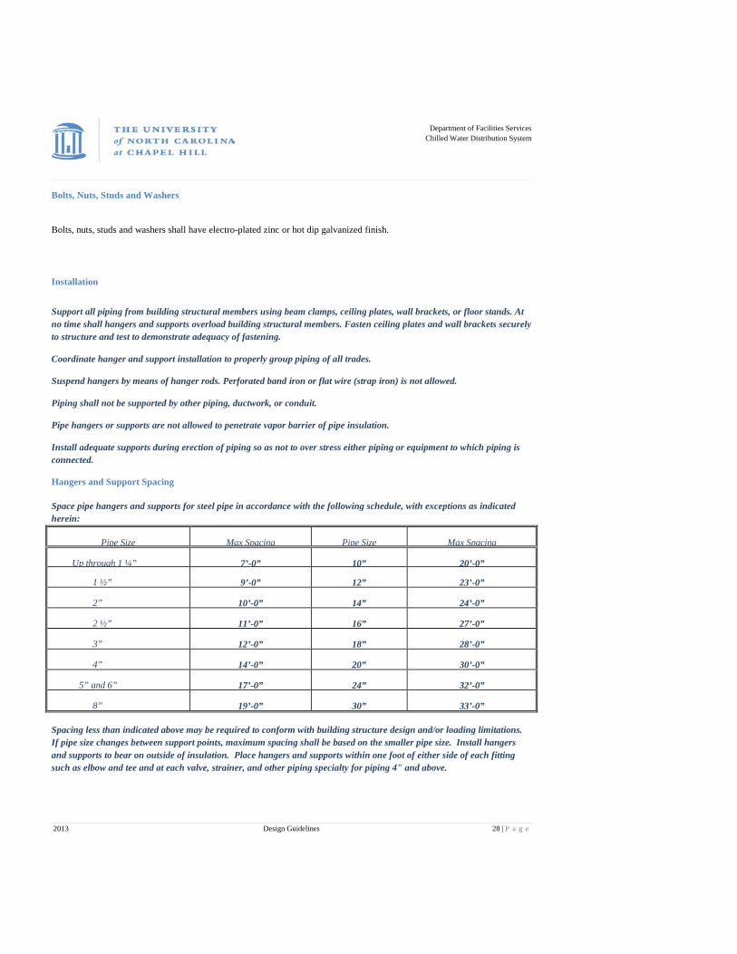
Hangers and Support Spacing
Space pipe hangers and supports for steel pipe in accordance with the following schedule, with exceptions as indicated herein:
Pipe Size Max Spacing Pipe Size Max Spacing
Up through 1 ¼” 7’-0” 10” 20’-0”
1 ½” 9’-0” 12” 23’-0”
2” 10’-0” 14” 24’-0”
2 ½” 11’-0” 16” 27’-0”
3” 12’-0” 18” 28’-0”
4” 14’-0” 20” 30’-0”
5” and 6” 17’-0” 24” 32’-0”
8” 19’-0” 30” 33’-0”
Spacing less than indicated above may be required to conform with building structure design and/or loading limitations. If pipe size changes between support points, maximum spacing shall be based on the smaller pipe size. Install hangers and supports to bear on outside of insulation. Place hangers and supports within one foot of either side of each fitting such as elbow and tee and at each valve, strainer, and other piping specialty for piping 4" and above.

Department of Facilities Services
Chilled Water Distribution System
2013 Design Guidelines 29 | P a g e
PIPING SYSTEM PRESSURE TEST
Coordinate pressure tests with Engineer and Chilled Water Engineer, in writing, at least 7 days in advance of its occurrence and conduct tests in presence of Engineer. Engineer has right to wave requirement for witnessing test. If engineer is not present, conduct test in presence of Construction Manager's representative. Representative shall sign report-verifying results. Contractor shall notify engineer of all tests to be performed.
Conduct pressure test prior to flushing and cleaning of piping systems. No systems shall be fully insulated until it has been successfully tested. Prior to the test being completed insulation can be installed if it does not cover welds, joints, fittings or penetrations.
Conduct hydrostatic (HYDRO) test at 150 psig with test medium of water unless otherwise indicated. For hydrostatic tests, remove air from piping being tested by means of air vents. If outlets are not available at high points, the Contractor shall make the necessary taps at points of highest elevations before the test is made.
The testing of the system shall be performed by a contractor experienced in pipe testing. The Contractor shall perform all phases of testing including supervision and provide pumps, calibrated gauges, instruments, test equipment, temporary piping and personnel required for tests and provide removal of test equipment and draining of pipes after tests have been successfully conducted.
Contractor should perform preliminary pressure test prior to witnessed record test to verify system will pass record test on first attempt. Pressure tests may be made of isolated portions of piping systems to facilitate general progress of installation. Any revisions made in piping systems require retesting of affected portions of piping systems. No pressure drop shall occur during test period. Any pressure drop during test period indicates leakage. If leaks are found, repair with new materials and repeat test; caulking or “JB Weld” will not be acceptable.
Measure and record test pressure at high point in system. Where test pressure at high point in system causes excessive pressure at low point in system, due to static head, portions of piping system may be isolated and tested separately to avoid undue pressure. However, every portion of piping system must be tested at the specified minimum test pressure.
Minimum test time shall be 4 hours plus such additional time as Chilled Water Engineer may require insuring there are no air pockets in the line, no broken pipe or defective materials are in the line, and no leaking joints have been made.
Repair system and retest all portions of system when equipment or system fails to meet minimum test requirements.
Submit results of each test to Engineer within 3 days of test occurrence for review.
FLUSHING AND CHEMICAL CLEANING OF CHILLED WATER ABOVE GROUND PIPE SYSTEMS
Contractor Qualifications
The Engineer must approve the contractor performing cleaning or supplying of the chemicals. Submit contractor qualifications and references for five (5) similar projects performed in the last 5 years. The contractor must also meet the following minimum requirements:
Performed a minimum of three (3) institutional piping cleanings within the last 5 years.
Has been in the chemical pipe cleaning or treatment business and has been performing this type of work for a minimum of 5 years.
Is licensed to perform work in the State of North Carolina.
Submittals
Department of Facilities Services
Chilled Water Distribution System
2013 Design Guidelines 30 | P a g e
NOTE: The Contractor shall provide their flushing plan to the designer at least two weeks before flushing is planned to begin. The designer shall verify the temporary piping is adequately sized to attain the required velocities in the piping.
Submit the following information:
Detailed plans on performing the flushing and cleaning. The plan must include a strainer with opening no larger than 0.45 inches. The strainer will be removed several times during the process for inspection.
Chemicals; description of chemicals, its composition and function.
Material Safety Data Sheets (MSDS): Submit directly to Owner the MSDS for all chemicals used for pipe cleaning. Include with MSDS written notice of Owner’s responsibility to notify its employees of the use of those chemicals.
Capacities/ratings
Materials of construction
Dimensions and weights
All other appropriate data
Chemical Manufacturers
Nalco or approved equal.
Piping System Cleaner
Use cleaning compound similar to Nalco 2567 - to remove organic soil, hydrocarbons, flux, pipe mill, varnish, pipe compounds, iron oxide, and like deleterious substances - with or without inhibitor, suitable for system metals without deleterious effects. Cleaner shall contain no trisodium phosphate.
Batch Chemical Feeder
Provide by-pass type batch feeder to receive chemicals in liquid or pellet form. Remove feeder from ME room when process is completed.
Execution
DESIGNER NOTE: Designer shall provide contractor with flushing flow needed to ensure the velocities in any section of piping exceeds 3.0 fps. This will be the minimum flow required to properly flush the entire system.
DESIGNER AND CONTRACTOR NOTE: The building chilled water pump may be used; if approved for use by the Chilled Water Manager; the pump has been aligned and verified by Chilled Water Personnel; VFD has been certified by VFD supplier and checked by Chilled Water personnel; flow is deemed sufficient by the designing engineer; is requested in writing 2 weeks in advance and a pump inspection is scheduled with the pump manufacturer’s service representative to determine no degradation is found. At a minimum the seal will be replaced during reassembly. If the building chilled water pump is not used, contractor shall isolate the building chilled water pumps and supply temporary pump and piping to perform flushing. Ensure that the temporary 1/8” mesh strainer is in place before the cleaning begins.
Department of Facilities Services
Chilled Water Distribution System
2013 Design Guidelines 31 | P a g e
The Contractor shall install temporary piping to facilitate the flushing at the end of piping runs. The temporary piping will be line size or 1/3 main line size depending upon location. The temporary piping will be installed off the bottom of the permanent piping, top take offs will not be allowed for flushing and cleaning. This will ensure that all foreign material is removed during cleaning. If horizontal connection is required for cleaning it must be line size and any reducers must be eccentric with the flat install on bottom edge of piping. The Contractor shall bypass all necessary equipment and sensitive components. The Contractor shall verify all lines being flushed are open with no strainers or filters in any line.
Contractor to flush and clean all new chilled water piping systems after the system has been successfully pressure tested. Chilled Water personnel shall witness the flushing and cleaning procedures. The Contractor shall provide all water for flushing and cleaning. Flushing water and cleaning solutions shall be discharged to the sanitary sewer system.
Flushing
Flush all chilled water pipe thoroughly for 30 minutes or longer, as required to remove all dirt and foreign matter from the system. UNC Construction Management representative will make determination if piping flush is complete before the Contractor can proceed to the cleaning step.
Cleaning
Drain the system.
Verify the strainer is clean before proceeding. Fill the system with water, vent and add recommended amount of cleaner. The cleaner should be diluted by at least a 3:1 ratio to prevent excessive attack on metal surfaces at the point of application. (Do not allow any chemicals to come in contact with galvanized surfaces.
Circulate system for a minimum of 24 hours at the flow rate recommended by the chemical manufacturer. Remove the temporary mesh strainer and debris. If temporary mesh strainer is not clean, reinstall and continue cleaning.
If UNC Construction Management representative determines the temporary mesh strainer is clean, completely drain system and continue to next step.
Fill system with clean water, vent and circulate for one hour. Drain system.
If installed, remove the temporary piping and pump. If building chilled water pumps were used, commence inspection with pump manufacturer’s service representative. After pump is inspected, realign and have alignment verified. Re-inspect for leakage and if no leakage is noted, delivery one new seal kit and bearings to Chilled Water representative.
Department of Facilities Services
Chilled Water Distribution System
2013 Design Guidelines 32 | P a g e
Final Fill
If piping is to be isolated from the system for more than 7 days, add inhibitor to prevent corrosion. Inhibitor shall be NALCO 3DT279. Molybdate inhibitor shall not be used. If the piping is being placed in service in less than 7 days, Chilled Water Personnel will fill the system with water from the University Chilled Water System.
MECHANICAL INSULATION
Product Delivery, Storage and Handling
All insulation material shall be delivered to project site in original, unbroken factory packaging labeled with product designation and thickness. Shipment of materials from manufacturer to installation location shall be in weathertight transportation. Insulation materials delivered to jobsite shall be stored so as to protect materials from moisture and weather during storage and installation. Insulation material shall be protected from long exposure to UV light from sun.
Application
Install Polyisocyanurate insulation as per manufacturer’s specifications.
Installation
Do not insulate any sections of piping that contain welded joints, threaded joints, flanges or instrumentation taps until the pressure test has been completed. Any removal and reinstallation to correct system defects, prior to end of guarantee period shall be accomplished at no expense to Owner.
All insulation installation methods shall be performed in accordance with the latest edition of National Commercial and Industrial Insulation Standards published by MICA (Midwest Insulation Contractors Association) and manufacturer's installation instructions, except as modified in this Section of specifications.
Install all products with good workmanship, with smooth and even surfaces. Use full-length factory furnished material where possible. Do not use scrap piecing. Apply insulation only on clean, dry surfaces, after all rust and scale have been removed and testing of systems has been completed.
Department of Facilities Services
Chilled Water Distribution System
2013 Design Guidelines 33 | P a g e
For pipes 1-1/2" and smaller, specified pipe insulation and jacket shall be continuous through hanger or support locations and insulation protection shields shall be provided to protect insulation from compressing.
For pipes 2" and larger, where manufactured pre-insulated pipe supports are used at hanger or support locations, extend insulation to insulated pipe supports. To ensure vapor barrier, the contractor shall be responsible for continuity of vapor barrier at insulated pipe supports. Use 3" wide vapor barrier tape at pipe supports.
For contractor fabricated anchors, secure insulation directly to pipe surface and extend up anchor for distance of 4 times insulation thickness. For pre-insulated anchors, cover entire surface of anchors with Type A insulation. Take special care to assure vapor seal at anchor.
PIPE IDENTIFICATION Install pipe identification on each system. Place flow directional arrows at each pipe identification location. Identify piping with marker system. Markers shall be "snap-on" or "strap-on" type depending on applicable pipe size. Identify all piping, not less than once every 25 ft, not less than once in each room, at each branch, adjacent to each access door or panel, at each valve and where exposed piping passes through walls and floors.
Pipe identification labels shall be abbreviated as follows:
Piping System Identification
Chilled Water Supply CWS
Chilled Water Return CWR
Markers to comply with ANSI A13.1 for color, length of color field and include flow directional arrows integrated into the marker.
For insulated pipe systems, lettering sizes are as follows:
For pipes up to 1 inch, use 1 inch letters.
For pipes 1-1/4 inch to 2 inches, use 2 inch letters.
For pipes 2-1/2 inches to 6 inches, use 3 inch letters.
For pipes above 6 inches, use 4 inch letters.

Department of Facilities Services
Chilled Water Distribution System
2013 Design Guidelines 34 | P a g e
BRIDGE CONTROLS
PRIMARY/SECONDARY BUILDING BRIDGE SYSTEM - DESCRIPTION OF OPERATION
A chilled water bridge system shall fall into one of two categories, depending on the kind of building loads that are served. The building category will be designated when the designer/engineer have reviewed the building loads with the Chilled Water Engineer/Manager. These categories are: (1) essential loads, (2) non-essential loads. The “non-essential loads” category generally includes comfort-cooling applications. The “essential loads” category includes research facilities, their auxiliary equipment, medical facilities with operating rooms, and computer facilities.
BRIDGE OPERATION FOR NON-ESSENTIAL AND ESSENTIAL LOADS
Building and EMCS Interface
The bridge enable shall be a hardwired 4 to 20MA signal (4=0% load and 20=100% load) from the Building Automation System to the Chilled Water Bridge controller. This signal represents the actual live total Chilled Water load in the building.
Current transformers (CTs) on pump starter input to the bridge controller and the bridge controller will energize solenoids for FV(B), which opens and FV(P) which closes. Where variable frequency drives are used, the bridge controller will energize the solenoids. When the building control system is used to provide this signal, outdoor air temperature, cooling coil valve output, or other parameters may be used to initiate bridge operation/shutdown. Designer shall specify parameter to be used. Bridge modes of operation will be controlled by chilled water based on the 4 to 20 mA signal from the BAS.
For an essential bridge, when building load drops below a predetermined level or in the event of a failure of the bridge controls/pumps, the bridge switches to the “coupled” mode.
Boost Coupled Mode
The mode is activated by Chilled Water when the Chilled Water Bridge pump motor can realize power savings without adversely affecting the utility return water temperature or when sufficient cooling cannot be achieved otherwise. This is accomplished by shutting the pump by-pass valve FV-P, shutting the bridge by-pass valve FV-B and forcing the TCV-A valve to 100% open. Pump speed modulates according to end of line differential set point or if no means of modulation is available then the pump is at full speed.
Decoupled Mode
Department of Facilities Services
Chilled Water Distribution System
2013 Design Guidelines 35 | P a g e
Water flow across the bridge interface is controlled by a two position spring-return-to-closed valve (FV-B) in the bridge bypass line, a two-position spring-return-to-open valve (FV-P) in the pump bypass line and a temperature control valve (TCV-A) in the distribution return branch line, and a VFD on the pump. A multi-loop digital controller (MC-1) provides regulatory and discreet control of the bridge system components. The normal mode of operation of the chilled water bridge is to “decouple” the building system from the chilled water distribution system.
In this mode the bridge bypass valve is open, the pump bypass valve is closed, the pump(s) is energized, and the bridge return temperature control valve regulates the flow of water across the bridge interface with the building system. The pump(s) circulates chilled water to the building loads at the required flow and pressure. A temperature control loop, consisting of temperature controller (MC-1), temperature sensors (TS-1) and (TS-3), and bridge return temperature control valve (TCV-A), regulates chilled water circulation between the chilled water distribution mains and the building system. The control loop maintains a return water temperature equal to or greater than set point. Set point is determined by the design cooling coil leaving water temperature.
Variable volume pumping shall be under the control of the bridge controller, provided by UNC Chilled Water. Provide differential pressure transmitter(s), PDT-1(2) and Variable Speed Drive(s). The control loop maintains a differential pressure equal to or greater than set point. Set point is determined by the design cooling coil and control valve requirements. The following signals must be provided between the variable frequency drive(s) and the bridge controller:
1. 4-20 mA isolated process follower output from bridge controller to drive(s).
2. 4-20 mA isolated Hz or % speed input to bridge controller from drive(s).
3. Dry contact is normally closed when the drive is de-energized or in the event of a fault. This dry contact shall be open when the drive is energized and not in fault.
4. Where a bypass starter is used, a dry contact to indicate bypass status.
5. Start/Stop command.
6. Run status.
7. kW
8. Spare
Coupled Mode
The mode is activated whenever the building load drops below a predetermined level. The designer shall provide for a signal from the building control system to switch to this mode under normal operating conditions. This signal shall cause the CHW circulation pumps(s) to stop, pump bypass valve FV-P to open, bridge bypass valve FV-B to close, and bridge return temperature control valve TCV-A to open and/or regulate to chilled water return set point.
Failure Mode
In a failure of the bridge controls or pump failure the position of the TCV-A will be determined by the type of bridge, in the event of a failure a non-essential valve will fail in the closed position and an essential valve will fail in the open position.
Department of Facilities Services
Chilled Water Distribution System
2013 Design Guidelines 36 | P a g e
INTERLOCKS AND METERING
BTU metering is available as an output of the MC-1 digital controller. The temperature difference of the distribution supply and return as sensed by TS-1 and TS-2 is multiplied by the flow rate as sensed by FE/FT-1. This value is integrated and becomes a digital output to totalizer NQI-l.
INSTRUMENT SPECIFICATIONS
The following field-mounted devices and functions shall be provided for all applications:
TAG NO. DESCRIPTION
PANEL Bridge Panel/Control Cabinet
The Bridge panel is supplied by UNC – Chilled Water Department at a time when requested by the contractor through UNC Construction Management. The panel is mounted in a place agreed upon by contractor and UNC Chilled Water Engineer. The power conduit shall enter the cabinet on the left side near the top of the cabinet. The network conduit shall enter the cabinet on the right side near the top of the cabinet. The panel shall be mounted and conduits and wiring to the field instruments installed before the back plane is requested and delivered. The wiring will be terminated in the panel by UNC – Chilled Water Department personnel.
INSTALLATION NOTE: No penetrations are allowed in the top of the panel box. All penetrations must be made with liquidtight connectors.
MC-1 Multi Loop Digital Controller
All control functions for this system are performed by a multi-loop controller. This controller will be purchased, programmed and installed in a control panel by Chilled Water Department. Before the installation of the back plane, the instruments and transmitters shall be checked out for communication and operational capability by UNC – Chilled Water personnel. To perform this testing all associated equipment for the operation must be completed, including compressed air lines and any other required equipment. Once this testing is completed, the back plane will be turned over to the contractor for installation. The controller shall be provided with two ethernet connections to the campus network.
Department of Facilities Services
Chilled Water Distribution System
2013 Design Guidelines 37 | P a g e
VFD Variable Frequency Drive
Designer Note: The VFD must not be powered up or operated until it has been certified by the VFD supplier’s personnel and verified by Chilled Water Personnel.
Drive efficiency, transient protection and harmonic distortion - Single phase, ground fault and short circuit protection (including bypass, if supplied), coordinated AC transient protection system consisting of 4-120 joule rated MOV’s (phase to phase and phase to ground), a capacitor clamp and 5% impedance reactors, (5% impedance may be from dual (positive and negative DC bus) reactors, or 5% AC line reactors), EMI/RFI filter, input current rating of the VFD shall be no more than 3% greater than the output current rating. Compliance to: Standard 519-1992, IEEE Guide for Harmonic Content and Control, UL508C, IEC 16800 Parts 1 and 2.
Operating Limits – Tolerated voltage window shall allow the VFD to operate from a line of +10% nominal, and -15% nominal voltage as a minimum. Environmental operating conditions: 0 to 40ºC continuous. VFD’s that can operate at 40ºC intermittently (during a 24 hour period) are not acceptable and must be oversized. Altitude 0 to 3300 feet above sea level, less than 95% humidity, non-condensing.
Motor winding protection – Standing wave attenuation between motor and drive shall be provided that limits rise time of the output PWM waveform to approximately 1.2 µs at highest carrier frequency, limits peak voltage to 1 kV, and reduces the voltage rise to less than 500 volts per micro-second. This effect shall be confirmed at the startup of the drive by measuring the PWM waveform voltages at the VFD and motor junctions, storing the waveforms with a digital oscilloscope, and generating a report with printed waveforms to be given to Chilled Water Personnel.
Control Features – Local drive interface shall be digital display and keypad, regardless of horsepower rating. The keypad shall allow for uploading and downloading of parameter settings as an aid for start-up of multiple VFDs. The keypad shall include Hand-Off-Auto selections, manual speed control, and fault reset. The drive shall incorporate “bump-less transfer” of speed reference when switching between “Hand” and “Auto” modes. All applicable operating values shall be capable of being displayed in engineering (user) units. A minimum of three operating values from the list below shall be capable of being displayed at all times. The display shall be in complete English words (alpha-numeric codes are not acceptable):
Output frequency Motor Speed (RPM, %, or EU)
Motor Current Calculated Motor Torque
Calculated Motor Power (kW) DC Bus Voltage
Output Voltage
Two (2) programmable analog inputs shall accept 4-20 ma current signals.
If the input reference (4-20 ma or 2-10V) is lost, the VFD shall give the user the option of either (1) stopping and displaying a fault, (2) running a programmable preset speed, (3) hold the VFD speed based on the last good reference received, or (4) cause a warning to be issued, as selected by the user. The drive shall be programmable to signal this condition via a keypad warning, relay output and/or over the serial communication bus.
The VFD shall have programmable “Sleep” and “Wake up” functions to allow the drive to be started and stopped from the level of a process feedback signal.
Two (2) programmable analog 4-20 ma outputs. The outputs may be programmed to output proportional to Frequency, Motor Speed, Output Voltage, Output Current, Motor Torque, Motor Power (kW), DC Bus Voltage, Active Reference.
Department of Facilities Services
Chilled Water Distribution System
2013 Design Guidelines 38 | P a g e
Six (6) programmable digital inputs for maximum flexibility in interfacing with external devices. All digital inputs shall be programmable to initiate upon an application or removal of 24 VDC or a dry contact.
Three (3) programmable digital Form-C relay outputs. The relays shall include programmable on and off delay times and adjustable hysteresis. Default settings shall be for run, not faulted (fail safe), and run permissive. The relays shall be rated for maximum switching current of 8 amps at 24 VDC and 0.4 amps at 250 VAC; maximum voltages of 300 VDC and 250 VAC; continuous current rating of 2 amps RMS. Outputs shall be true form C type contacts; open collector outputs are not acceptable.
Two independently adjustable accel and decel ramps with 1 – 1800 seconds adjustable time ramps.
The VFD shall include a motor flux optimization circuit that will automatically reduce applied motor voltage to the motor to optimize energy consumption and audible motor noise.
The VFD shall include a carrier frequency control circuit that reduces the carrier frequency based on actual VFD temperature that allows the highest carrier frequency without de-rating the VFD or operating at higher frequency only at low speeds.
The VFD shall be capable of starting into a coasting load (forward or reverse) up to full speed and accelerate or decelerate to set-point without safety tripping or component damage (flying start).
The VFD shall have the ability to automatically restart after an over-current, over-voltage, under-voltage, or loss of input signal protective trip. The number of restart attempts, trial time, and time between attempts shall be programmable.
The overload rating of the drive shall be 110% of its normal duty current rating for 1 minute every 10 minutes, 130% overload for 2 seconds. The minimum FLA rating shall meet or exceed the values in the NEC/UL table 430-150 for 4-pole motors.
The VFD shall include password protection against parameter changes.
Construction and Serviceability – The VFD shall have cooling fans that are designed for easy replacement. The fans shall be designed for replacement without removing the VFD from its mounting or removal of circuit boards. The VFD cooling fans shall operate only when required. To extend the fan and bearing operating life and limit condensation, operating temperature will be monitored and used to cycle the fans on and off as required. The VFD cabinet must be a NEMA 3R rated enclosure with fused service disconnect, manual bypass, and mechanical motor overloads. It shall allow the motor to be operated across the line with full over-current protection while drive is removed for repair/replacement. The manual bypass feature shall be activated by a selector switch and control circuit separate from the drive controls. Drive and bypass contactors must be energized by manual door mounted switches, via an internal control transformer. There must be no “electronic bypass” provided. Electronic 'bypass’ consist of control boards that energize contactors, and provide electronic motor overload protection. It much provide status for bypass operation. Motors are to be located within 50 feet from drive, output cables shall be installed in rigid steel conduit. Output filter or load reactor, if required, shall be mounted in drive cabinet.
Communication – Modbus RTU serial communication protocol, RS 485 multi-drop. The use of third party gateways or multiplexers is not acceptable. Serial communication capabilities shall include, but not limited to; run-stop control, speed set adjustment, proportional/integral/derivative PID control adjustments, current limit, accel/decal time adjustments, and lock and unlock the keypad. The drive shall have the capability of allowing the DDC to monitor feedback such as process variable feedback, output speed/frequency, current (in amps), % torque, power (kW), kilowatt hours (resettable), operating hours (resettable), and drive temperature. Status monitoring the VFD relay output status, digital input status, and all analog input and analog output values, keypad “Hand” or “Auto” selected, bypass selected, and the ability to force the unit to bypass (if bypass is specified). All diagnostic warning and fault information shall be transmitted over the serial communication bus. Remote VFD fault reset shall be possible.

Department of Facilities Services
Chilled Water Distribution System
2013 Design Guidelines 39 | P a g e
Startup – A certified start-up form shall be filled out for each drive with a copy provided to Chilled Water, a copy provided with project documentation and a copy kept on file at the drive manufacturer.
Design Note: No auto transfer to bypass in case of drive fault.
Design Note: No DCS start command required for bypass operation.
Installation Note: Separate conduit shall be used for input power wiring, motor wiring, control and communications wiring and if supplied, brake unit wiring.
Start Up Note: Testing needs to be coordinated with UNC-Chilled Water to allow UNC personnel to be on hand during startup.
TCV-A Return Temperature Control Valve
For valve sizes 2” and larger use a high performance butterfly control valve with a 60 psi pneumatic rotary diaphragm actuator and positioner capable of receiving a 4-20mA control signal, with integral HART communication. The valve and the actuator shafts shall be connected with a two piece no play coupling. The coupling and connecting bracket shall be manufacturer supplied and not shop built.
The valve shall have a lugged wafer style body of carbon steel, ductile iron or stainless steel rated for ANSI class 150 service. The seat material shall be fluoropolymer based blend with no fillers or PTFE filled. Disk and shaft shall be 316 Stainless steel construction. Disk to shaft connection shall be non-shear tangential pinning. Disk shall be offset from shaft centerline. The valve shall have upper and lower shaft bushing/bearings of a 316 stainless steel carrier and PTFE liner. Shaft seal shall be multiple rings of V-flex style PTFE packing with 316 stainless steel packing ring.
Actuator shall have a position indicator with pointer and scale showing 0 to 100% rotation or “open” “closed”. Actuator shall be capable of opening and closing valve against 50 psi differential. Actuator shall be spring to close for non-essential applications and spring to open for essential applications. The actuator shall be sized for an air supply of 60 PSIG and shall be supplied with an automatic filter regulator with a minimum 5 micron filter supplied with the assembly.
Preferred valve orientation is with the shaft in the horizontal plane. When mounted in the vertical plane, the actuator assembly must not be located at the bottom of the pipe. The position indicator must be visible from the ME room floor. There must be sufficient clearance to remove the actuator assembly from the valve. Specify actuator mounting position with valve order. Slip-on flanges shall not be used for control valve installation and can only be used if approved for installation by UNC Chilled Water Manager.
Positioner shall have 4 – 20 mA control signal with integral HARTcommunication and use <0.07 scfm of compressed air when bleeding off.

Department of Facilities Services
Chilled Water Distribution System
2013 Design Guidelines 40 | P a g e
INSTALLATION NOTE: Bench-check valve action and travel limits before installation. Notify UNC-CM representative of bench-check so UNC-CW personnel can witness testing.
Manufacturer: Jamesbury (valve size in inches), 815 L - 11 21 36 XZ – QP(n)C/M with ND9000 series positioner or approved equal.
Alternate TCV-A Return Temperature Control Valve
For valves 1” to 6” in spaces where compressed air is not available, use a single V-ball control valve with an electric actuator and positioner capable of receiving a 4-20 mA control signal, with integral HART communication.
The valve body shall have ANSI 150 lb flange ends, carbon steel body, removable soft seat, stainless steel ball and stem with splined connection, PTFE V-ring packing and low flow restriction design. The valve shall have upper and lower shaft bushing/bearings of a 316 stainless steel carrier and PTFE liner.
Actuator shall be 120 VAC power with a 4-20 mA feedback module, capable of HART communication. Actuator shall have a position indicator with pointer and scale. The valve and the actuator shafts shall be connected with a two piece no play coupling. The coupling and connecting bracket shall be manufacturer supplied and not shop built. Actuator shall be capable of opening and closing the valve against 50 psi differential. Actuator will have 100% duty factor and sufficient power to move with breakaway torque levels at any position. The actuator shall be spring close or spring open depending upon application or the valve will be supplied with alternate power option which will allow the valve to be moved and held in its failure position.
Manufacturer: KTM model W0601 valve, with EPI2 electric actuator or approved equal
FV-B, FV-P Bypass Valves
Both FV-B and FV-P, the bridge bypass valve and the pump bypass valve respectively, are to be line size valves.
For valve sizes 2” and larger use a high performance butterfly control valve with a 60 psi pneumatic rotary diaphragm actuator. The assembly shall be capable of being field reversible for changing operation. The valve and the actuator shafts shall be connected with a two piece no play coupling. The coupling and connecting bracket shall be manufacturer supplied and not shop built.
The valve shall have a lugged wafer style body of carbon steel or ductile iron rated for ANSI class 150 service. The seat material shall be fluoropolymer based blend with no fillers or PTFE filled. Disk and shaft shall be 316 Stainless steel construction. Disk to shaft connection shall be non-shear tangential pinning. Disk shall be offset from shaft centerline. The valve shall have upper and lower shaft bushing/bearings of a 316 stainless steel carrier and PTFE liner. Shaft seal shall be multiple rings of V-flex style PTFE packing with 316 stainless steel packing ring.
Actuator shall have a position indicator with pointer and scale showing 0 to 100% rotation or “open” “closed”. Actuator shall be capable of opening and closing valve against 50 psi differential. FV-B shall be spring-to-close, FV-P shall be spring-to-open. The actuator will be supplied with a 115 VAC solenoid. The solenoid shall be integral with the actuator. The actuator shall be sized for an air supply of 60 PSIG and shall be supplied with an automatic filter regulator with a minimum 5 micron filter supplied with the assembly. A separate 120 VAC power circuit is required for each solenoid.
Preferred valve orientation is with the shaft in the horizontal plane. When mounted in the vertical plane, the actuator assembly must not be located at the bottom of the pipe. The position indicator must be visible from the ME room floor. There must be sufficient clearance to remove the actuator assembly from the valve. Specify actuator mounting position with valve order. Slip-on flanges shall not be used for control valve installation.
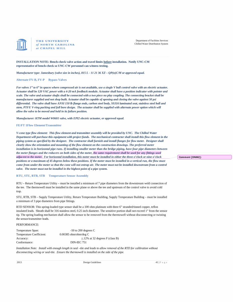
Department of Facilities Services
Chilled Water Distribution System
2013 Design Guidelines 41 | P a g e
INSTALLATION NOTE: Bench-check valve action and travel limits before installation. Notify UNC-CM representative of bench-check so UNC-CW personnel can witness testing.
Manufacturer type: Jamesbury (valve size in inches), 815 L - 11 21 36 XZ – QP(n)C/M or approved equal.
Alternate FV-B, FV-P Bypass Valves
For valves 1” to 6” in spaces where compressed air is not available, use a single V ball control valve with an electric actuator. Actuator shall be 120 VAC power with a 4-20 mA feedback module. Actuator shall have a position indicator with pointer and scale. The valve and actuator shafts shall be connected with a two piece no play coupling. The connecting bracket shall be manufacturer supplied and not shop built. Actuator shall be capable of opening and closing the valve against 50 psi differential. The valve shall have ANSI 150 lb flange ends, carbon steel body, SS316 laminated seat, stainless steel ball and stem, PTFE V-ring packing and full bore design. The actuator shall be supplied with alternate power option which will allow the valve to be moved and held in its failure position.
Manufacturer: KTM model W0601 valve, with EPI2 electric actuator, or approved equal.
FE/FT 1 Flow Element/Transmitter
V-cone type flow element: This flow element and transmitter assembly will be provided by UNC. The Chilled Water Department will purchase this equipment with project funds. The mechanical contractor shall install this flow element in the piping system as specified by the designer. The contractor shall furnish and install flanges for flow meter. Designer shall clearly show the orientation and mounting of the flow element on the construction drawings. The preferred meter installation is in horizontal pipe runs. If installing smaller meter than the bridge piping, have four pipe diameters between the meter flanges and the reducers on both sides of the meter, the same requirement shall be used for any fittings used adjacent to the meter. For horizontal installation, this meter must be installed in either the three o’clock or nine o’clock positions or a maximum of 45 degrees below these positions. If the meter must be installed in a vertical run, the flow must come from under the meter so that the cone will not entrap air. The meter must not be installed downstream from a control valve. The meter must not be installed in the highest point of a pipe system.
RTU, STU, RTB, STB Temperature Sensor Assembly
RTU – Return Temperature Utility – must be installed a minimum of 7 pipe diameters from the downstream weld connection of the tee. The thermowell must be installed in the same plane or above the tee and upstream of the control valve to avoid cold trap.
STU, RTB, STB – Supply Temperature Utility, Return Temperature Building, Supply Temperature Building – must be installed a minimum of 3 pipe diameters from pipe fittings.
RTD SENSOR: This spring-loaded type sensor shall be a 100 ohm platinum with three 6” stranded/tinned copper, teflon insulated leads. Sheath shall be 316 stainless steel, 0.25 inch diameter. The sensitive portion shall not exceed 1” from the sensor tip. The spring loading mechanism shall allow the sensor to be removed from the thermowell without disconnecting or twisting the sensor/transmitter leads.
PERFORMANCE:
Temperature Span: -50 to 200 degrees C Temperature Coefficient: 0.00385 ohm/ohm/deg C Accuracy: +.12% at 32 degrees F (class B) Conformance: DIN-IEC 751
Installation Note: Install with enough length in seal –tite and leads to allow removal of the RTD for calibration without disconnecting wiring or seal-tite. Ensure the thermowell is installed on the side of the pipe.
Comment [DNM2]:

Department of Facilities Services
Chilled Water Distribution System
2013 Design Guidelines 42 | P a g e
Thermowell for RTD Sensor
The thermowell shall have 1.75”connection head length with ½” FNPT instrument mounting, ¾” MNPT process-mount, .5” outside diameter and .26” bore. The insertion depth shall be as stated in chart below. The thermowell shall be compatible with the specified temperature sensor and be constructed of 316 stainless.
Pipe Size Insertion Depth
Sensor Length
Up to 4” 2.5”
7”
6”-12” 4.5” 9” 12” and above 7.5” 12”
Thermometers
Select devices for highest pressures and temperatures existing in respective systems in accordance with ANSI specifications.
Glass thermometer: Thermometer shall be an industrial glass thermometer with cast aluminum body and have a 9” scale. The scale will be from 30º to 120ºF degree scale with 2ºF degree division. The thermometer shall have a 3 ½” stem and variable degree angle adjustment and union connection. Solar thermometer: Thermometer shall be an industrial solar powered thermometer capable of reading a temperature range 30º to 120ºF with an accuracy of + 2%.
Thermowell for Thermometer
The thermowell shall have ¾” MNPT process mount, with 1 1/8” instrument mounting, and 3 ½” length. The thermowell shall be compatible with the specified thermometer and be constructed of brass.
BE Bridge Enable Signal
The bridge enable shall be a hardwired 4 to 20MA signal (4=0% load and 20=100% load) from the Building Automation System to the Chilled Water Bridge controller. This signal represents the actual live total Chilled Water load in the building.
For example, all the cooling control valve positions would be averaged together to base the output signal on. If there were three cooling control valves that represented 100% of the total cooling load and valve 1 was 25% open , valve 2 was 50% open and valve 3 was 75% open the average load would 50% and the bridge enable signal would be at 12 mA. If there is equipment with no feedback some other means of accounting for actual live load shall be factored in to the total load.
All factors that are considered in the total load formula shall be bound out into a network output that can be read directly from the Building Automation System with our SCADA system via Modbus TCP. If necessary a device such as a fieldserver or other approved device may need to be installed to ensure that the most reliable and most direct means of data transmission is accomplished. The cooling coil tube velocity at design flow shall not be less than 4 FPS. Provide a leaving chilled water temperature sensor on all heat exchangers (cooling coils) over 10 tons rated cooling capacity.
PDT–1, 2 Differential Pressure Transmitter
PDT-1 shall provide a linear output signal proportional to process differential pressure (DP) for control of building chilled water pump VFD. Sensor shall be capacitance-type.
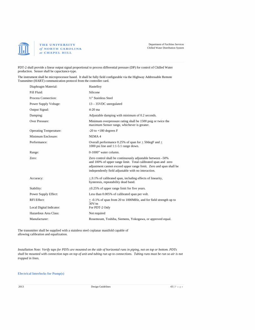
Department of Facilities Services
Chilled Water Distribution System
2013 Design Guidelines 43 | P a g e
PDT-2 shall provide a linear output signal proportional to process differential pressure (DP) for control of Chilled Water production. Sensor shall be capacitance-type.
The instrument shall be microprocessor based. It shall be fully field configurable via the Highway Addressable Remote Transmitter (HART) communication protocol from the controller card.
Diaphragm Material: Hastelloy
Fill Fluid: Silicone
Process Connection: ½” Stainless Steel
Power Supply Voltage: 13 – 35VDC unregulated
Output Signal: 4-20 ma
Damping: Adjustable damping with minimum of 0.2 seconds.
Over Pressure: Minimum overpressure rating shall be 1500 psig or twice the maximum Sensor range, whichever is greater.
Operating Temperature: -20 to +180 degrees F
Minimum Enclosure: NEMA 4
Performance: Overall performance 0.25% of span for + 50degF and + 1000 psi line and 1:1-5:1 range down.
Range: 0-1000” water column.
Zero: Zero control shall be continuously adjustable between –50% and 100% of upper range limit. Total calibrated span and zero adjustment cannot exceed upper range limit. Zero and span shall be independently field adjustable with no interaction.
Accuracy: + 0.1% of calibrated span, including effects of linearity, hysteresis, repeatability dead band.
Stability: +0.25% of upper range limit for five years.
Power Supply Effect: Less than 0.005% of calibrated span per volt.
RFI Effect: + -0.1% of span from 20 to 1000MHz, and for field strength up to 30V/m
Local Digital Indicator: For PDT-2 Only
Hazardous Area Class: Not required
Manufacturer: Rosemount, Toshiba, Siemens, Yokogawa, or approved equal.
The transmitter shall be supplied with a stainless steel coplanar manifold capable of allowing calibration and equalization.
Installation Note: Verify taps for PDTs are mounted on the side of horizontal runs in piping, not on top or bottom. PDTs shall be mounted with connection taps on top of unit and tubing run up to connections. Tubing runs must be run so air is not trapped in lines.
Electrical Interlocks for Pump(s)

Department of Facilities Services
Chilled Water Distribution System
2013 Design Guidelines 44 | P a g e
The contractor shall provide all interfaces between starter or variable speed drive and bridge control panel. Contacts shall be rated for low level electronic signal loads. < = 10mA at 24vdc. This shall include a circuit to start and stop the pump(s) and an isolated circuit for pump(s) status indication.
Installation Note: All power cables shall be installed in one continuous run.
Instrumentation Cables
Control cable type: Alpha no. 2241C or Belden no. 8760, 2-conductor twisted, 18 gauge, foil shield with drain wire, Stranded, Tinned, PVC jacket.
RTD Temperature Sensors: Alpha no. 2413C or Belden no. 8772, 3-conductor twisted, 18 gauge, foil shield with drain wire, Stranded, Tinned, PVC jacket
Installation Note: The cables shall be installed in one continuous run with all shield drain wires grounded at the control panel. The field ends of the shield drain wires shall be dressed and insulated. VFD and controller ends will be dressed with shrink wrap and labeled per Chilled Water provided termination sheet.
Pneumatic or Instrumentation Lines
All pneumatic lines for chilled water valves must be run from an air dryer and supplied with a filter regulator set. All lines must be stainless steel or soldered copper, plastic air lines are not permitted.
Conduit for Power and Instrumentation
All conduit for wiring shall be rigid galvanized steel conduit. Conduit will be run for all bridge panel wiring. All conduits will have similar wiring installed only.
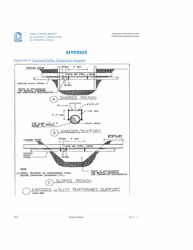
Department of Facilities Services
Chilled Water Distribution System
2013 Design Guidelines 45 | P a g e
APPENDIX
Appendix A Exposed Utility Temporary Support
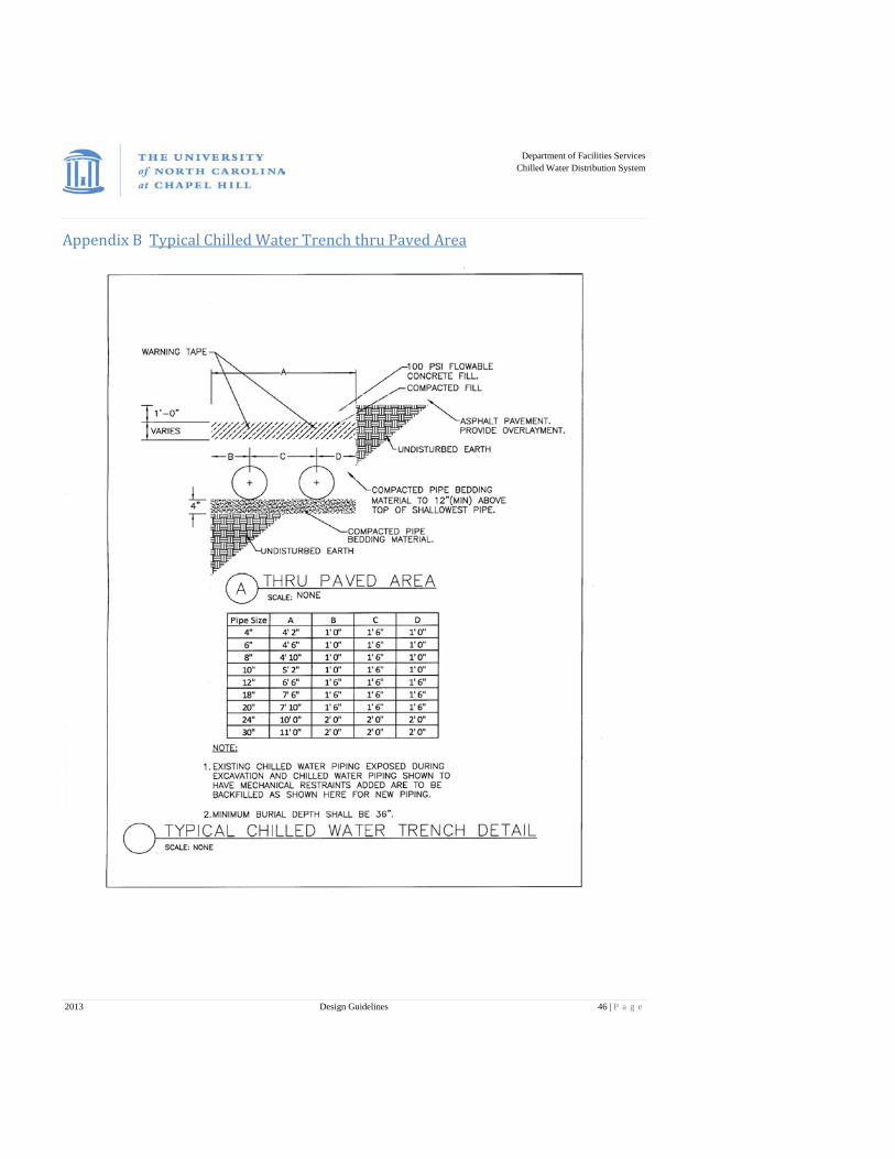
Department of Facilities Services
Chilled Water Distribution System
2013 Design Guidelines 46 | P a g e
Appendix B Typical Chilled Water Trench thru Paved Area
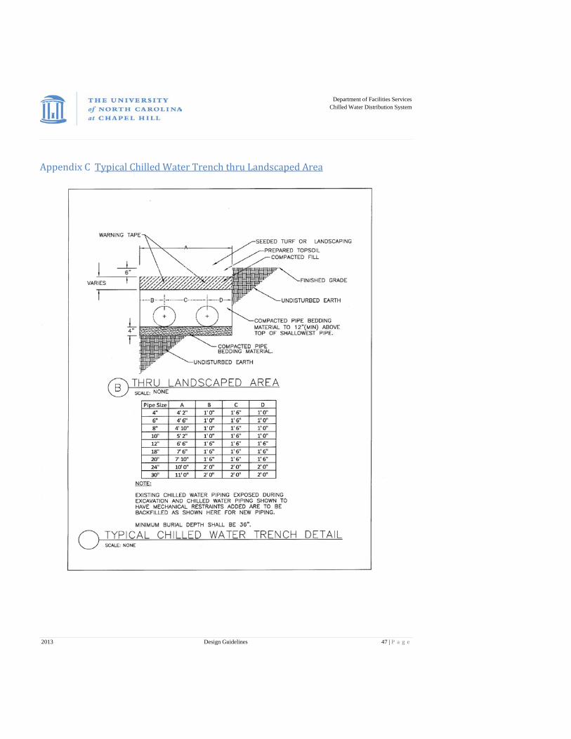
Department of Facilities Services
Chilled Water Distribution System
2013 Design Guidelines 47 | P a g e
Appendix C Typical Chilled Water Trench thru Landscaped Area
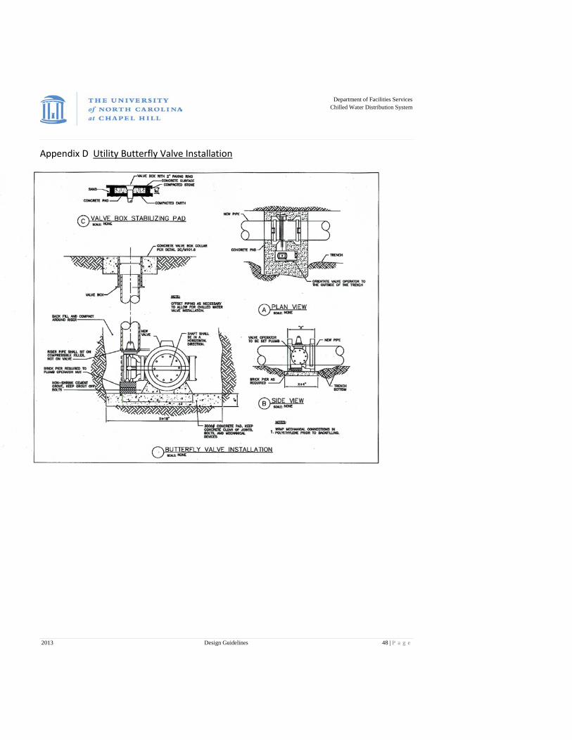
Department of Facilities Services
Chilled Water Distribution System
2013 Design Guidelines 48 | P a g e
Appendix D Utility Butterfly Valve Installation
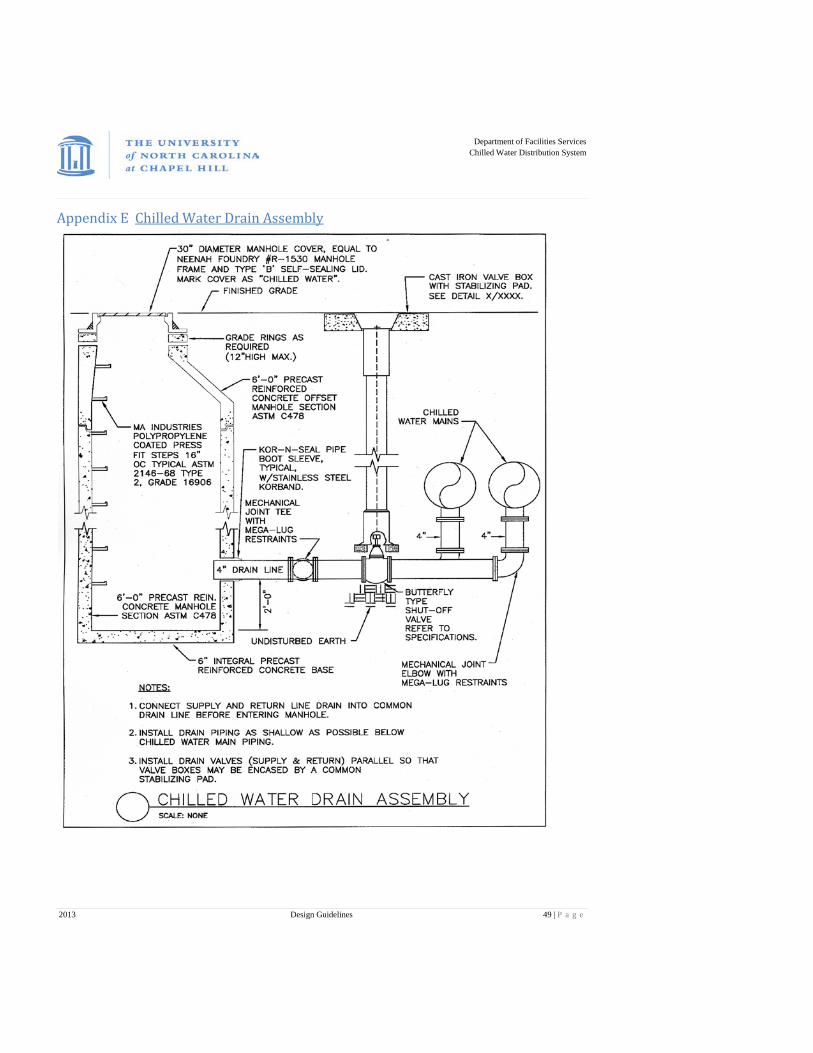
Department of Facilities Services
Chilled Water Distribution System
2013 Design Guidelines 49 | P a g e
Appendix E Chilled Water Drain Assembly
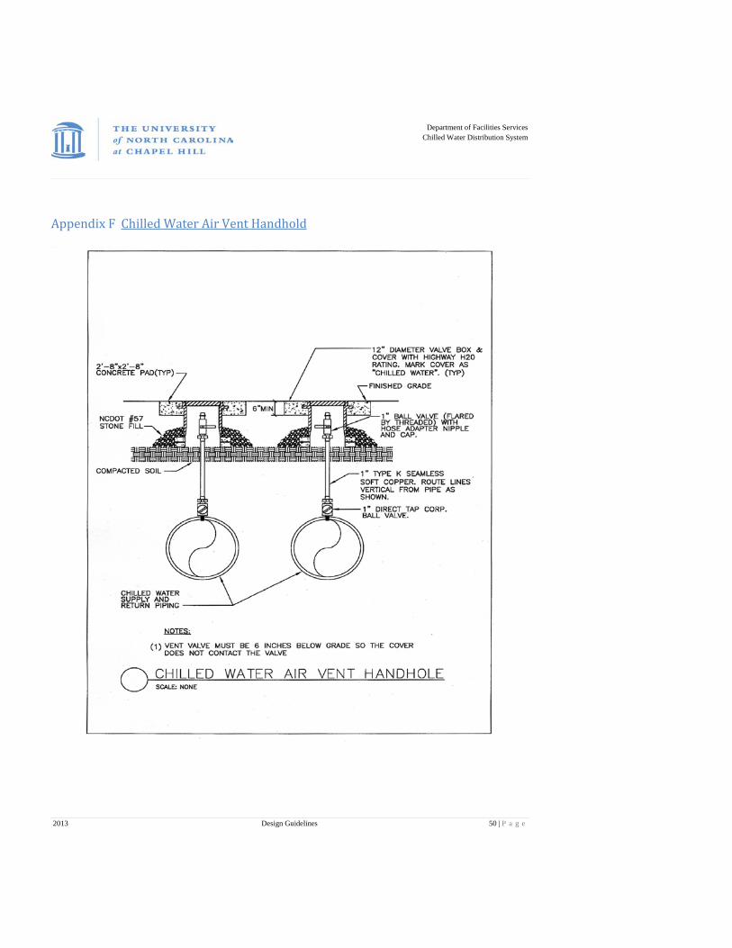
Department of Facilities Services
Chilled Water Distribution System
2013 Design Guidelines 50 | P a g e
Appendix F Chilled Water Air Vent Handhold
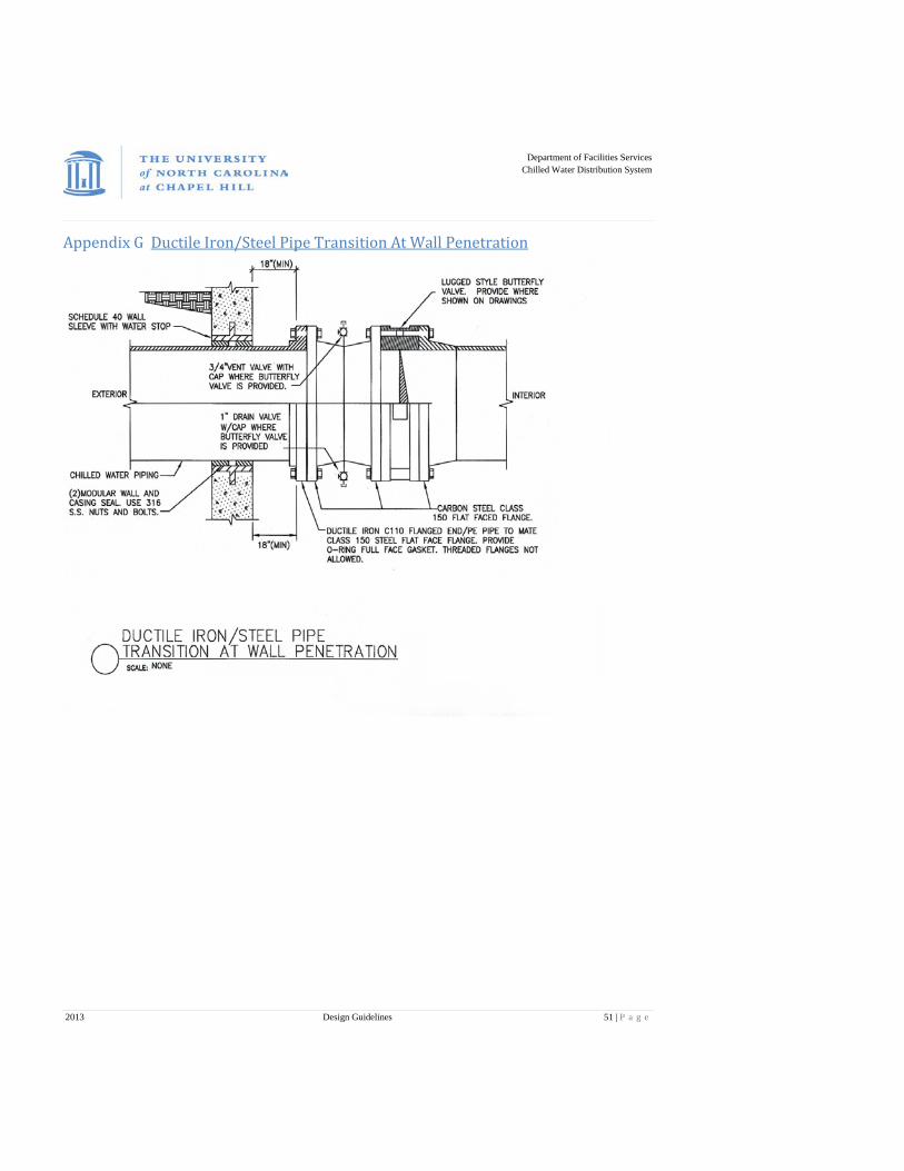
Department of Facilities Services
Chilled Water Distribution System
2013 Design Guidelines 51 | P a g e
Appendix G Ductile Iron/Steel Pipe Transition At Wall Penetration
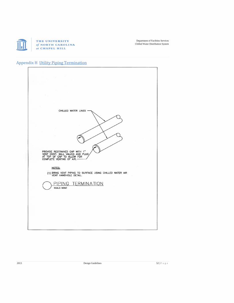
Department of Facilities Services
Chilled Water Distribution System
2013 Design Guidelines 52 | P a g e
Appendix H Utility Piping Termination
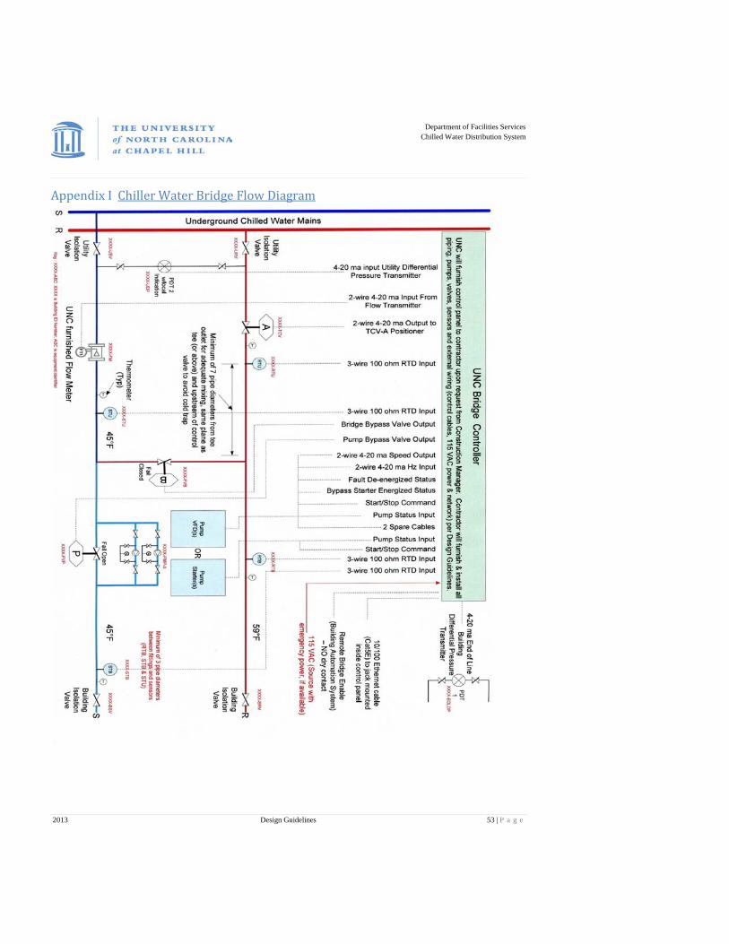
Department of Facilities Services
Chilled Water Distribution System
2013 Design Guidelines 53 | P a g e
Appendix I Chiller Water Bridge Flow Diagram

Department of Facilities Services
Chilled Water Distribution System
2013 Design Guidelines 54 | P a g e
Appendix J Pump Differential Pressure Gauge Detail
Department of Facilities Services
Chilled Water Distribution System
2013 Design Guidelines 55 | P a g e
Appendix K Requesting Outage for Chilled Water Service Requests for planned outages of chilled water to any facility will only be accepted from the Facility Service Department involved in the work being done, Construction Management or a Contractor providing construction or renovation services on campus. All requests must be received no less than 5 business days in advance of the start date of the work.
Procedure for Requesting a Chilled Water Outage
1. Gather the following information and submit to UNC Chilled Water Department using Appendix L of these Specifications:
• Name of Facility Service Department, Construction Manager or Contractor submitting request along with their contact information.
• Description of work to be preformed. • Name of Customer/Department and Building Name. • List of any Building Contacts or occupants who are aware of the work that needs to be accomplished. • Begin and End Times for Outage.
2. Prior to confirming an outage can be accommodated, Chilled Water will review the real or potential impact of the request. The review will include:
• Impact on other customers • Potential impact of weather to initiate or complete the service outage • Any special or unusual material needs for service restoration • A plan to complete work and restore chilled water to the affected buildings • Time required to complete work and restore chilled water to the affected buildings
3. Once the review is completed and outage is acceptable, confirmation will be provided to the requesting party. Should any considerations be of sufficient concern to require further evaluation or delay, Chilled Water will inform the requesting party of reasons and alternatives.
4. Once the outage request has been accepted UNC Customer Service will be notified. They will issue a blanket notification to building occupants and other UNC Departments that might be affected. Chilled Water will post notices on the building no later than 48 hours prior to the outage starting.
5. Prior to restoring service, Chilled Water will contact the requesting party to confirm the system can safely be restored with no danger to any personnel associated with or involved in the outage.
6. At the completion of the outage, Chilled Water will issue a blanket notification to building occupants and other UNC Departments through UNC Customer Service and will remove posted notices.

Department of Facilities Services
Chilled Water Distribution System
2013 Design Guidelines 56 | P a g e
Contact Information
For any questions or concerns, please contact Chilled Water at 962-1448.
Appendix L Request for Chilled Water Outage
Request for a Chilled Water Outage
A request for a chilled water outage needs to be submitted at least 5 working days before the outage is needed. This allows us to set the outage up with the proper contacts and arrange for any personnel needs that the outage may require.
Organization requesting outage:
Person requesting outage:
Outage location:
Reason for outage:
Date and duration of outage:
Contact Person:
Phone Number:__________________________________