checking piston valve clearance
TRANSCRIPT

Jomer B. Almozara
Reporter
Checking Piston-Valve Clearance

To check this clearance, the crankshaft, piston, and rod must be installed in the block. After installing the piston and rod, temporarily install the cylinder head, along with the head gasket and valve train. Just remember that if hydraulic lifters are used, they will need to be pumped up first, and lighter test springs should be used in place of the stock valve springs so that the valves will open fully. The clearance can be checked by using one of two methods: the clay method or the dial indicator method. Both methods show you the minimum amount of clearance between the piston and the valve. The clay method gives an imprint of where the valve and piston have an interference issue, so that you will be better able to determine how to fly cut the pistons if necessary. The dial indicator method allows you to check the clearance at various positions of the piston.
Step 1
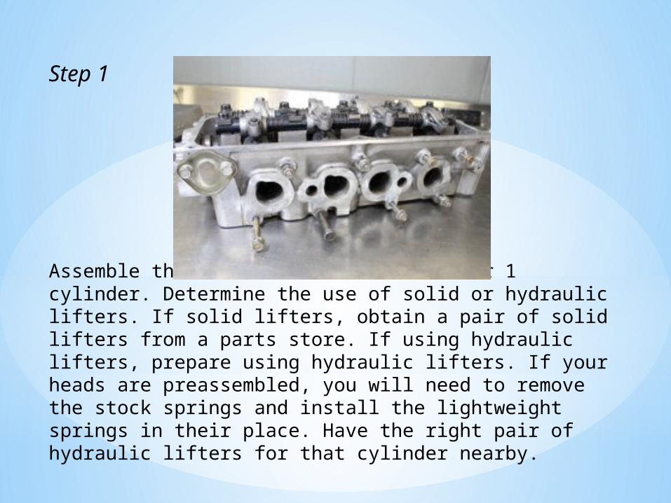
Assemble the valve train for the number 1 cylinder. Determine the use of solid or hydraulic lifters. If solid lifters, obtain a pair of solid lifters from a parts store. If using hydraulic lifters, prepare using hydraulic lifters. If your heads are preassembled, you will need to remove the stock springs and install the lightweight springs in their place. Have the right pair of hydraulic lifters for that cylinder nearby.

Step 2
Install lightweight test springs. Put a little piece of wood, or something similar, under the valve to keep it in the closed position while you install the lightweight springs. Check that the pistons are not protruding above the deck. They should be set fractionally below the deck. Measure the clearance by sliding a feeler gauge under a straightedge laid across the cylinder.
Step 3
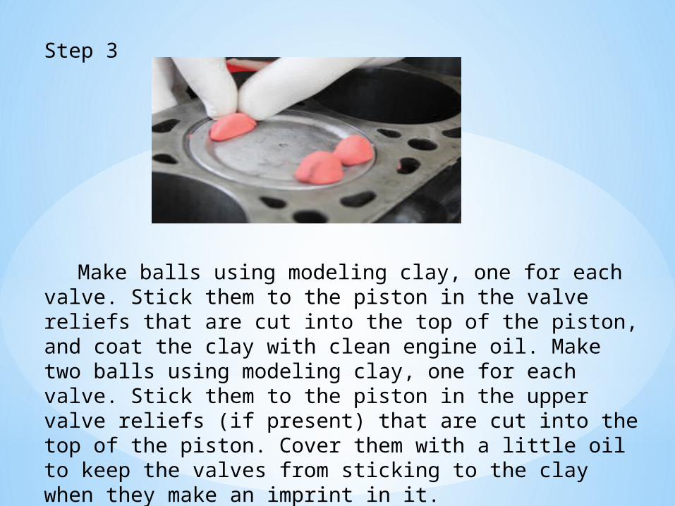
Make balls using modeling clay, one for each valve. Stick them to the piston in the valve reliefs that are cut into the top of the piston, and coat the clay with clean engine oil. Make two balls using modeling clay, one for each valve. Stick them to the piston in the upper valve reliefs (if present) that are cut into the top of the piston. Cover them with a little oil to keep the valves from sticking to the clay when they make an imprint in it.
Step 4
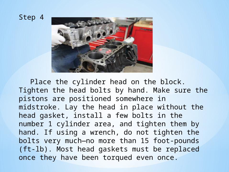
Place the cylinder head on the block. Tighten the head bolts by hand. Make sure the pistons are positioned somewhere in midstroke. Lay the head in place without the head gasket, install a few bolts in the number 1 cylinder area, and tighten them by hand. If using a wrench, do not tighten the bolts very much—no more than 15 foot-pounds (ft-lb). Most head gaskets must be replaced once they have been torqued even once.

Step 5
Install the valve train and adjust the valves to the specified lash, or if using hydraulic lifters, zero lash. Install the valve train and adjust the valves to the specified lash, if applicable. If the engine uses hydraulic lifters, set the clearance to zero lash.
Step 6
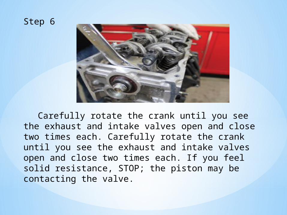
Carefully rotate the crank until you see the exhaust and intake valves open and close two times each. Carefully rotate the crank until you see the exhaust and intake valves open and close two times each. If you feel solid resistance, STOP; the piston may be contacting the valve.

Step 7
Remove the valve train and head. Cut each piece of clay and remove half. Measure the distance from the piston to the top of the valve imprint with a ruler or the depth end of a dial caliper.
Now remove the valve train and head. When you remove the head, the two balls of clay now have valve imprints pressed into them. Cut each piece of clay and remove half. Measure the distance from the piston to the top of the valve imprint with a ruler or the depth end of a dial caliper. Compare this measurement with the specification in the service information. If it is greater than the minimum allowed, there is very little danger of your valves contacting the piston once the engine is heated up and running, unless the valves float at high engine revolutions per minute (rpm). If the clearance is smaller than specified, the pistons will need to be fly cut by a machine shop, or a smaller camshaft must be installed. Clean any leftover clay off the piston.

Compression Test
Your car's engine compression can tell you a lot about the overall health of the engine. If your car is blowing blue smoke out of the tailpipe, or if your car is losing lots of oil, you could have a bad piston ring. This will also cause low compression in that cylinder, and a compression test will tell you. The same goes for a bad valve. Even if you are just noticing a general lack of power, a compression test can help you rule out some of the more serious possible causes. *Note: This test was performed on an ancient Porsche engine to demonstrate the basics of how a compression test works. Please consult your repair manual for specific instructions on your vehicle.
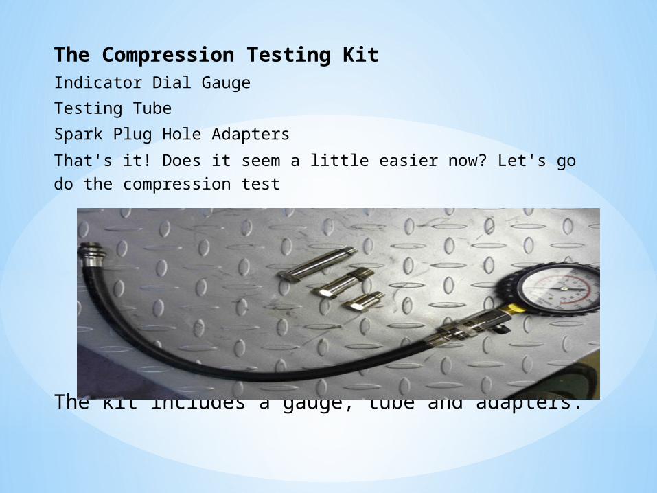
The Compression Testing KitIndicator Dial Gauge
Testing Tube
Spark Plug Hole Adapters
That's it! Does it seem a little easier now? Let's go do the compression test
The kit includes a gauge, tube and adapters.
Before You Begin
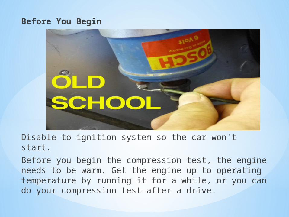
Disable to ignition system so the car won't start.
Before you begin the compression test, the engine needs to be warm. Get the engine up to operating temperature by running it for a while, or you can do your compression test after a drive.

Be careful. Some parts of the engine can be very hot!
You'll also need to disable your ignition system. We are going to need to crank the starter to turn the engine over but we don't want it to actually start. In most cars simply disconnect the ECU. If your car has an old school coil like the one pictured above, remove the wire from the terminal marked 15. If your car has a coil pack type distributorless ignition, unplug the coil pack or packs. Please consult your repair manual to find out what's specific to your vehicle.
*Engine at operating temperature.*Ignition system disabled.
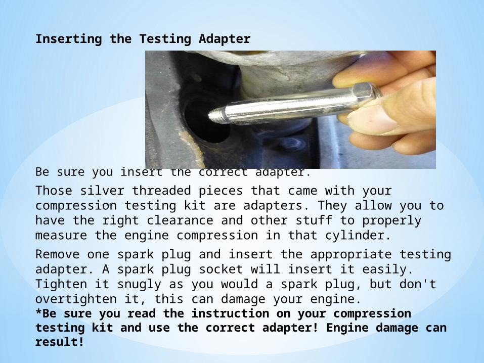
Inserting the Testing Adapter
Be sure you insert the correct adapter.
Those silver threaded pieces that came with your compression testing kit are adapters. They allow you to have the right clearance and other stuff to properly measure the engine compression in that cylinder.
Remove one spark plug and insert the appropriate testing adapter. A spark plug socket will insert it easily. Tighten it snugly as you would a spark plug, but don't overtighten it, this can damage your engine. *Be sure you read the instruction on your compression testing kit and use the correct adapter! Engine damage can result!

Screw In the Testing Tube
Screw in the testing tube.
With the correct adapter snugly in place, screw the long black testing tube onto the silver adapter. It's a pain in the neck to screw in, but just keep turning the whole thing like a giant straw until its snug.
Do not tighten the tube with a tool! Hand tight is enough.
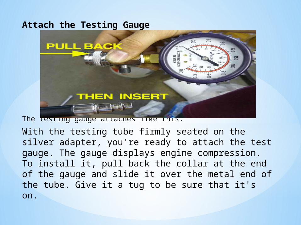
Attach the Testing Gauge
The testing gauge attaches like this.
With the testing tube firmly seated on the silver adapter, you're ready to attach the test gauge. The gauge displays engine compression. To install it, pull back the collar at the end of the gauge and slide it over the metal end of the tube. Give it a tug to be sure that it's on.
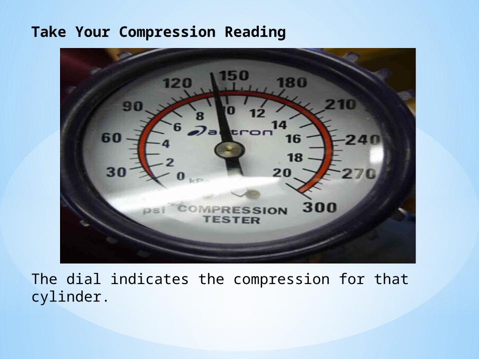
Take Your Compression Reading
The dial indicates the compression for that cylinder.

You're all set up now and ready to actually
do the compression test. Double check that you disconnected the appropriate stuff so the engine doesn't actually start. Now turn the key and crank the engine over for about 10 seconds. The needle on the compression gauge will stay at the highest indicated compression reading. This number indicates the compression for that cylinder only. Record it so that you can compare it to the other readings you're about to take.
Don't remove the gauge just yet!

Remove the Gauge and Repeat
Release the pressure and you're on to the next cylinder.
Don't just remove the gauge, there's a lot of pressure in the line and you want to release it first. Thankfully they thought of this, and there's a little button on the side. Depress the button and you'll hear the pressure hiss out. Now it's safe to remove the gauge, unscrew the testing tube, and take out the adapter.
Replace the spark plug and repeat the whole process on the next cylinder until you have readings for all of them. Check your repair manual to see if the readings you got are healthy.
