characterization and formation mechanism of nano-structured hydroxyapatite coatings deposited by the...
TRANSCRIPT
This content has been downloaded from IOPscience. Please scroll down to see the full text.
Download details:
IP Address: 128.197.26.12
This content was downloaded on 29/09/2014 at 12:53
Please note that terms and conditions apply.
Characterization and formation mechanism of nano-structured hydroxyapatite coatings
deposited by the liquid precursor plasma spraying process
View the table of contents for this issue, or go to the journal homepage for more
2010 Biomed. Mater. 5 054113
(http://iopscience.iop.org/1748-605X/5/5/054113)
Home Search Collections Journals About Contact us My IOPscience
IOP PUBLISHING BIOMEDICAL MATERIALS
Biomed. Mater. 5 (2010) 054113 (7pp) doi:10.1088/1748-6041/5/5/054113
Characterization and formationmechanism of nano-structuredhydroxyapatite coatings deposited by theliquid precursor plasma spraying processYi Huang, Lei Song, Tao Huang, Xiaoguang Liu, Yanfeng Xiao, Yao Wu,Fang Wu and Zhongwei Gu
National Engineering Research Center for Biomaterials, Sichuan University, Chengdu 610064,People’s Republic of China
E-mail: [email protected]
Received 19 January 2010Accepted for publication 11 May 2010Published 28 September 2010Online at stacks.iop.org/BMM/5/054113
AbstractNano-structured hydroxyapatite (HA) coatings were deposited on the Ti-6Al-4V alloysubstrate by the liquid precursor plasma spraying (LPPS) process. The thermal behavior of theHA liquid precursor was analyzed to interpret the phase change and structure transformationduring the formation process of the nano-structured HA coatings. The phase composition,structure and morphology of the nano-structured HA coatings were characterized by x-raydiffraction (XRD), scanning electron microscope (SEM) and Fourier transform infrared (FTIR)spectroscopy. The XRD spectra showed that the coatings deposited by the LPPS processmainly consisted of the HA phase and the crystallite size was measured to be 56 nm. The SEMobservation showed that the as-deposited LPPS coatings had small splat size, and nano-scaleHA particles were found in certain regions of the coating surface. The FTIR spectroscopyshowed the strong presence of the OH− group in the as-deposited LPPS coatings, indicating asuperior structural integrity. In addition, the coatings deposited by the LPPS process were alsocarbonated HA coatings. The results indicate that the LPPS process is a promising plasmaspraying technique for depositing nano-structured HA coatings with unique microstructuralfeatures that are desirable for improving the biological performance of the HA coatings.
1. Introduction
Hydroxyapatite (HA; Ca10(PO4)6(OH)2) coatings depositedby the atmospheric plasma spraying (APS) process havebeen commonly used for orthopedic and dental applications[1–6]. However, the APS process generally acquires HAcoatings with coarse grains due to the nature of the APSprocess [7]. The main inorganic constituent of natural boneis composed of nano-structured HA crystals [8–10]. Nano-structured HA is desirable for achieving better biologicalproperties compared to that of coarser grained HA [11, 14].The literature has reported that nano-structured HA has apositive impact on cell–biomaterial interaction [12, 13].
There have been various techniques to deposit nano-structured HA coatings, such as electrochemical deposition[14], sol–gel method [15], biomimetic method [16],electrohydrodynamic atomization spraying [17], micro-arcoxidation [18], electrophoretic deposition [19] and electron-beam deposition [20]. However, these techniques generallyproduce coatings with either relatively lower adhesion strengthor very thin coating thickness. Therefore, most of thesetechniques have been limited to laboratory research, notsuitable for the commercial production on a large scale dueto the poor deposition efficiency and relatively high cost.
In order to overcome the drawbacks of the aforementionedtechniques and further improve the biological performance ofthe HA-coated implant, we have applied the liquid precursor
1748-6041/10/054113+07$30.00 1 © 2010 IOP Publishing Ltd Printed in the UK
Biomed. Mater. 5 (2010) 054113 Y Huang et al
plasma spraying (LPPS) process to fabricate nano-structuredHA coatings on the Ti-6Al-4V alloy substrate. The LPPSprocess is an emerging plasma spraying technique firstreported by Karthikeyan et al in 1997 [21], which has beenapplied in the synthesis of a variety of materials, including ananosized ceramic powder [22–24], thermal barrier coatings[25], solid oxide fuel cell [26], phosphor coatings [27], etc.The LPPS process selects the liquid precursor as the feedstockfor the plasma spraying, which is atomized into mist andinjected into the plasma jet, instead of the powder feedstockcommonly used in the APS process. Recently, Pawlowskiet al have used suspension plasma spraying to synthesize HAcoatings [28–30], where solid HA powders were mixed withliquid media to form a suspension for plasma spraying.
In this study, the liquid precursor prepared through wetchemical synthesis has been directly used as the feedstock forplasma spraying of HA coatings, in order to take full advantageof the composition homogeneity at a molecular level of the wetchemical synthesis, and the robust production efficiency of theplasma spraying process. The phase composition, structureand morphology of the liquid precursor and as-deposited HAcoatings have been characterized by a transmission electronmicroscope (TEM), thermogravimetry-differential scanningcalorimetry (TG-DSC), Fourier transform infrared (FTIR)spectroscopy, x-ray diffraction (XRD) and a scanning electronmicroscope (SEM). The formation mechanism of the nano-structured HA coatings in the LPPS process has also beenexplored.
2. Materials and methods
2.1. Preparation and characterization of the HA liquidprecursor
The HA liquid precursor was prepared by a wet chemicalmethod in our laboratory according to the following reaction:10Ca(NO3)2+6(NH4)2HPO4+8NH4OH=Ca10(PO4)6(OH)2+20NH4NO3+6H2O. The 2.03 mol L−1 (NH4)2HPO4 aqueoussolution was added into a stirred 1.69 mol L−1 Ca(NO3)2
aqueous solution on the basis of a Ca/P atomic ratio of 1.67.The pH value of the solution mixture was adjusted to 11with ammonia solution (NH4OH, 30 wt%) and the reactionwas kept at 70 ◦C for 48 h. The solid content of the HAliquid precursor was about 25 wt%. The particle size andmorphology of the HA liquid precursor were observed bythe TEM (JEM-100CXII, JEOL Ltd, Japan). The HA liquidprecursor was dried on a hot plate at 40 ◦C to form the driedHA precursor powder. The TG-DSC (STA 449C Jupiter,NETZSCH Group, Germany) was used simultaneously toinvestigate the thermal behavior of the as-dried HA precursorpowder, which was heated to 1500 ◦C in the nitrogen flux at aheating rate of 10 ◦C min−1. Meanwhile, FTIR spectroscopy(170SX, Thermo Nicolet Limited, USA) was performed toidentify the structure evolution of the as-dried HA precursorpowder heat-treated at different temperatures, including 200,300, 700, 900, 1100, 1300 and 1470 ◦C. The as-dried HAprecursor powder was compressed into a potassium bromide(KBr) plate for FTIR analysis. Each heat treatment wasperformed at a heating rate of 10 ◦C min−1 for a hold time of1 h.
2.2. Fabrication of HA coatings using the LPPS and APSprocesses
During the LPPS process, the HA liquid precursor mist wasinjected into the plasma jet through an atomizing nozzle(BETE 1/8XASR150A-B@7, BETE Fog Nozzle Inc., USA).The HA coatings were deposited by a direct current plasmatorch (Metco MN plasma spraying system, Sulzer Metco Ltd,USA), which was attached to the thermal spraying robotic arm(AR2000, Sulzer Metco Ltd, USA). Nitrogen and hydrogenwere used as the primary and secondary plasma gases of theplasma spraying system, and the power input to plasma was36 kW. The stand-off distance of the LPPS process was 80 mm.For comparison, the HA powder was also used as feedstockfor plasma spraying in the conventional APS process, with aplasma spraying power of 24 kW. The APS process selectedonly nitrogen as the primary gas and the stand-off distance was120 mm. Both HA coatings were deposited on the sand-blasted(Al2O3 sands of 40 meshes, 392–686 kPa sand-blast pressure)Ti-6Al-4V alloy substrate (�20 × 5 mm). The thicknessesof the coatings deposited by the LPPS and APS processeswere all about 100 μm. For simplification, the HA coatingsdeposited by the LPPS and APS processes will be referred toas the LPPS and APS coatings hereafter in this paper.
2.3. Characterization of HA coatings
The crystalline phase compositions of the as-deposited LPPSand APS coatings were characterized using the XRD (X’PertMPD DY1291, Koninklijke Philips Electronics NV, TheNetherlands) with Cu Kα radiation at 40 kV and 35 mA.The XRD patterns were collected over a 2θ range from 20◦ to50◦ at a scanning rate of 2◦ min−1. The XRD patterns wereidentified using the Jade 5.0 software (Materials Data, Inc.,USA) which used the database of the International Centre ofDiffraction Data. The detailed powder diffraction file number(PDF no) used in the present study mainly included PDF no09-0432 (hydroxyapatite, HA), PDF no 09-0348 (α-tricalciumphosphate, α-TCP), PDF no 09-0169 (β-tricalcium phosphate,β-TCP), PDF no 70-1379 (tetracalcium phosphate, TTCP) andPDF no 82-1690 (calcium oxide, CaO). The crystallite size ofthe preferred orientation of the (0 0 2) plane was estimatedbased on the broadening of the peaks of crystalline phases,according to the following Scherrer formula: D = 0.89λ
cos θ√
B2−b2 ,where D is the mean crystallite size, λ is the wavelength of thex-ray, θ is the diffraction angle of reflection of the (0 0 2) plane,B is the full width at half maximum of the (0 0 2) plane and b isthe instrumental broadening which is equal to 0.1. The phasestructures of the APS and LPPS coatings were characterized byFTIR spectroscopy (170SX, Thermo Nicolet Limited, USA).The APS and LPPS coatings were first removed from thesubstrate and then compressed into the KBr plate for the FTIRanalysis. The morphologies of the LPPS and APS coatingswere observed using the SEM (S4800, Hitachi Ltd, Japan)at an acceleration voltage of 20 kV. Before observation, thesamples were coated with gold using an ion sputter (E-1010,Hitachi Ltd, Japan).
2
Biomed. Mater. 5 (2010) 054113 Y Huang et al
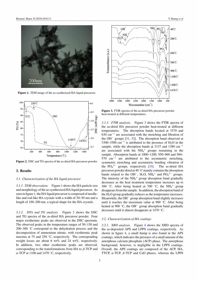
Figure 1. TEM image of the as-synthesized HA liquid precursor.
Figure 2. DSC and TG spectra of the as-dried HA precursor powder.
3. Results
3.1. Characterization of the HA liquid precursor
3.1.1. TEM observation. Figure 1 shows the HA particle sizeand morphology of the as-synthesized HA liquid precursor. Asseen in figure 1, the HA liquid precursor is composed of needle-like and rod-like HA crystals with a width of 30–50 nm and alength of 100–200 nm, a typical shape for the HA crystals.
3.1.2. DTA and TG analysis. Figure 2 shows the DSCand TG spectra of the as-dried HA precursor powder. Fourmajor exothermic peaks are observed in the DSC spectrum.The observed peaks in the temperature ranges of 50–150 and200–300 ◦C correspond to the dehydration process and thedecomposition of ammonium nitrate, with exothermic peakmaxima at 75 and 250 ◦C, respectively. The correspondingweight losses are about 6 wt% and 24 wt%, respectively.In addition, two other exothermic peaks are observed,corresponding to the transformations from HA to β-TCP andα-TCP at 1100 and 1470 ◦C, respectively.
Figure 3. FTIR spectra of the as-dried HA precursor powderheat-treated at different temperatures.
3.1.3. FTIR analysis. Figure 3 shows the FTIR spectra ofthe as-dried HA precursor powder heat-treated at differenttemperatures. The absorption bands located at 3570 and630 cm−1 are associated with the stretching and libration ofthe OH− groups [31, 32]. The absorption band observed at3300–3500 cm−1 is attributed to the presence of H2O in thesample, while the absorption bands at 3137 and 1380 cm−1
are associated with the NH4+ groups remaining in the
sample. Absorption bands at 1000–1200, 950–960 and 560–570 cm−1 are attributed to the asymmetric stretching,symmetric stretching and asymmetric bending vibration ofthe PO4
3− groups, respectively [33]. The as-dried HAprecursor powder dried at 40 ◦C mainly contains the absorptionbands related to the OH−, H2O, NH4
+ and PO43− groups.
The intensity of the NH4+ group absorption band gradually
decreases as the heat treatment temperature increases up to300 ◦C. After being heated at 700 ◦C, the NH4
+ groupdisappears from the sample. In addition, the absorption band ofthe H2O group gradually reduces as the temperature increases.Meanwhile, the OH− group absorption band slightly increasesuntil it reaches the maximum value at 900 ◦C. After beingheated at 900 ◦C, the OH− group absorption band graduallydecreases until it almost disappears at 1470 ◦C.
3.2. Characterization of HA coatings
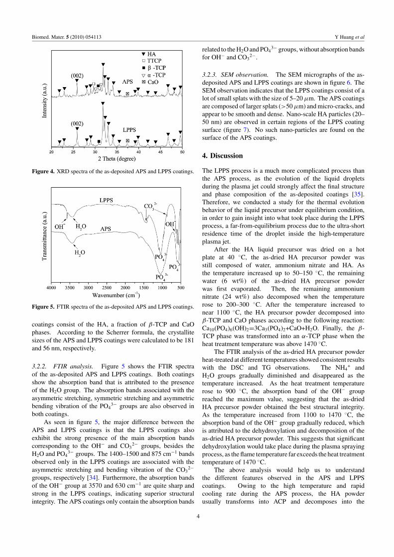
3.2.1. XRD analysis. Figure 4 shows the XRD spectra ofthe as-deposited APS and LPPS coatings, respectively. Asshown in figure 4, a small hump is also found in the APScoatings, which indicates the presence of a small amount of theamorphous calcium phosphate (ACP) phase. The amorphousbackground, however, is negligible in the LPPS coatings.Overall, the APS coatings are composed of the ACP, HA,TTCP, α-TCP, β-TCP and CaO phases, whereas the LPPS
3
Biomed. Mater. 5 (2010) 054113 Y Huang et al
Figure 4. XRD spectra of the as-deposited APS and LPPS coatings.
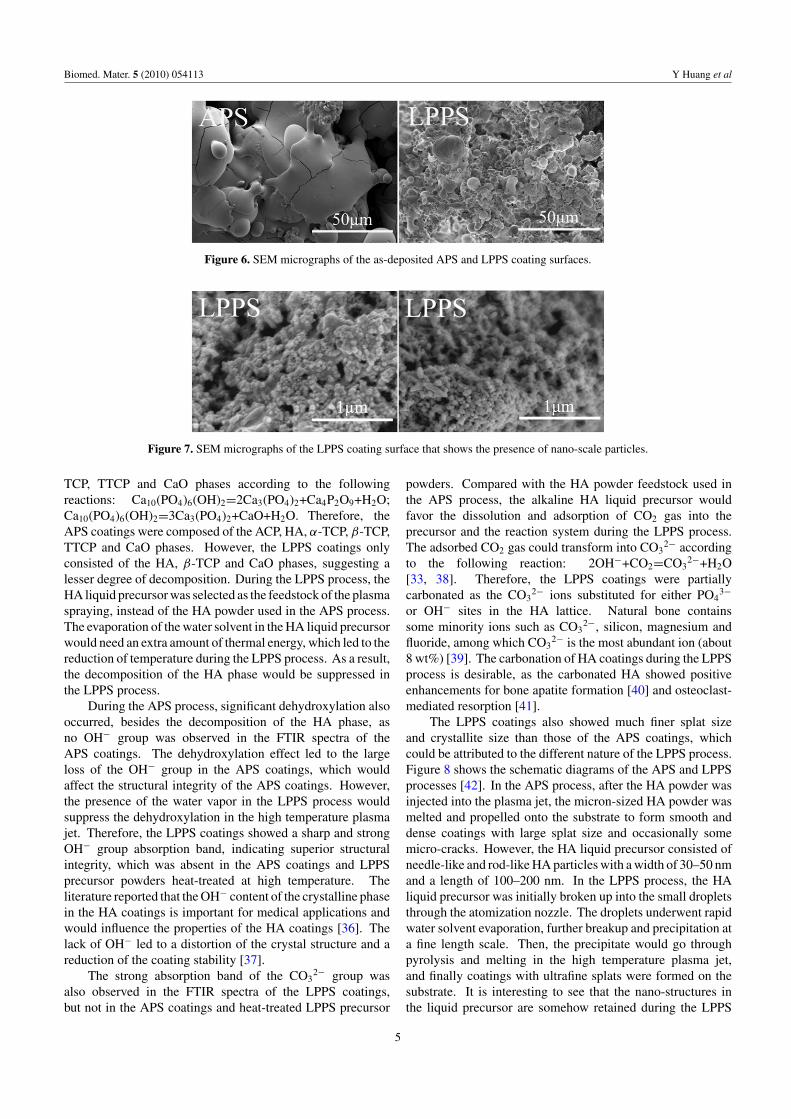
Figure 5. FTIR spectra of the as-deposited APS and LPPS coatings.
coatings consist of the HA, a fraction of β-TCP and CaOphases. According to the Scherrer formula, the crystallitesizes of the APS and LPPS coatings were calculated to be 181and 56 nm, respectively.
3.2.2. FTIR analysis. Figure 5 shows the FTIR spectraof the as-deposited APS and LPPS coatings. Both coatingsshow the absorption band that is attributed to the presenceof the H2O group. The absorption bands associated with theasymmetric stretching, symmetric stretching and asymmetricbending vibration of the PO4
3− groups are also observed inboth coatings.
As seen in figure 5, the major difference between theAPS and LPPS coatings is that the LPPS coatings alsoexhibit the strong presence of the main absorption bandscorresponding to the OH− and CO3
2− groups, besides theH2O and PO4
3− groups. The 1400–1500 and 875 cm−1 bandsobserved only in the LPPS coatings are associated with theasymmetric stretching and bending vibration of the CO3
2−
groups, respectively [34]. Furthermore, the absorption bandsof the OH− group at 3570 and 630 cm−1 are quite sharp andstrong in the LPPS coatings, indicating superior structuralintegrity. The APS coatings only contain the absorption bands
related to the H2O and PO43− groups, without absorption bands
for OH− and CO32−.
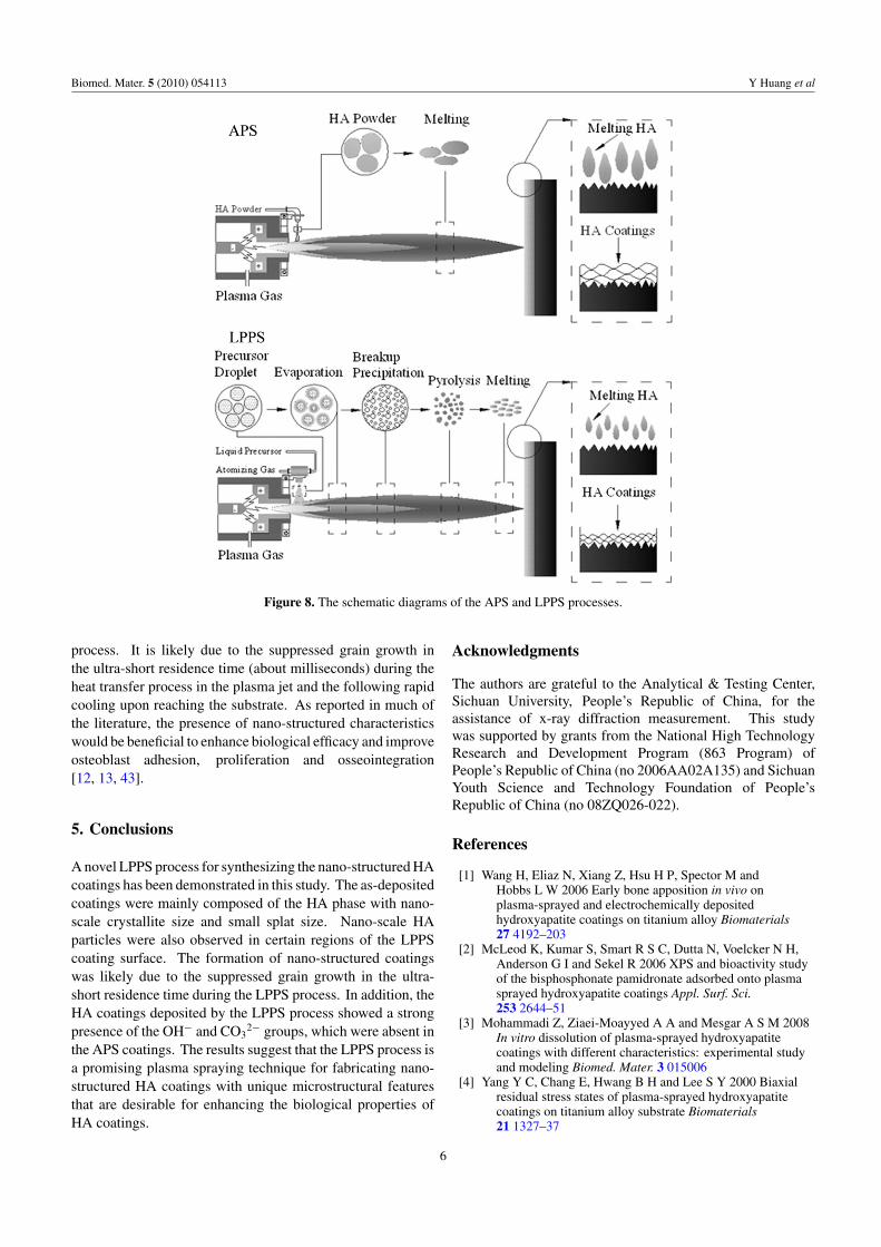
3.2.3. SEM observation. The SEM micrographs of the as-deposited APS and LPPS coatings are shown in figure 6. TheSEM observation indicates that the LPPS coatings consist of alot of small splats with the size of 5–20 μm. The APS coatingsare composed of larger splats (>50 μm) and micro-cracks, andappear to be smooth and dense. Nano-scale HA particles (20–50 nm) are observed in certain regions of the LPPS coatingsurface (figure 7). No such nano-particles are found on thesurface of the APS coatings.
4. Discussion
The LPPS process is a much more complicated process thanthe APS process, as the evolution of the liquid dropletsduring the plasma jet could strongly affect the final structureand phase composition of the as-deposited coatings [35].Therefore, we conducted a study for the thermal evolutionbehavior of the liquid precursor under equilibrium condition,in order to gain insight into what took place during the LPPSprocess, a far-from-equilibrium process due to the ultra-shortresidence time of the droplet inside the high-temperatureplasma jet.
After the HA liquid precursor was dried on a hotplate at 40 ◦C, the as-dried HA precursor powder wasstill composed of water, ammonium nitrate and HA. Asthe temperature increased up to 50–150 ◦C, the remainingwater (6 wt%) of the as-dried HA precursor powderwas first evaporated. Then, the remaining ammoniumnitrate (24 wt%) also decomposed when the temperaturerose to 200–300 ◦C. After the temperature increased tonear 1100 ◦C, the HA precursor powder decomposed intoβ-TCP and CaO phases according to the following reaction:Ca10(PO4)6(OH)2=3Ca3(PO4)2+CaO+H2O. Finally, the β-TCP phase was transformed into an α-TCP phase when theheat treatment temperature was above 1470 ◦C.
The FTIR analysis of the as-dried HA precursor powderheat-treated at different temperatures showed consistent resultswith the DSC and TG observations. The NH4
+ andH2O groups gradually diminished and disappeared as thetemperature increased. As the heat treatment temperaturerose to 900 ◦C, the absorption band of the OH− groupreached the maximum value, suggesting that the as-driedHA precursor powder obtained the best structural integrity.As the temperature increased from 1100 to 1470 ◦C, theabsorption band of the OH− group gradually reduced, whichis attributed to the dehydroxylation and decomposition of theas-dried HA precursor powder. This suggests that significantdehydroxylation would take place during the plasma sprayingprocess, as the flame temperature far exceeds the heat treatmenttemperature of 1470 ◦C.
The above analysis would help us to understandthe different features observed in the APS and LPPScoatings. Owing to the high temperature and rapidcooling rate during the APS process, the HA powderusually transforms into ACP and decomposes into the
4
Biomed. Mater. 5 (2010) 054113 Y Huang et al
Figure 6. SEM micrographs of the as-deposited APS and LPPS coating surfaces.
Figure 7. SEM micrographs of the LPPS coating surface that shows the presence of nano-scale particles.
TCP, TTCP and CaO phases according to the followingreactions: Ca10(PO4)6(OH)2=2Ca3(PO4)2+Ca4P2O9+H2O;Ca10(PO4)6(OH)2=3Ca3(PO4)2+CaO+H2O. Therefore, theAPS coatings were composed of the ACP, HA, α-TCP, β-TCP,TTCP and CaO phases. However, the LPPS coatings onlyconsisted of the HA, β-TCP and CaO phases, suggesting alesser degree of decomposition. During the LPPS process, theHA liquid precursor was selected as the feedstock of the plasmaspraying, instead of the HA powder used in the APS process.The evaporation of the water solvent in the HA liquid precursorwould need an extra amount of thermal energy, which led to thereduction of temperature during the LPPS process. As a result,the decomposition of the HA phase would be suppressed inthe LPPS process.
During the APS process, significant dehydroxylation alsooccurred, besides the decomposition of the HA phase, asno OH− group was observed in the FTIR spectra of theAPS coatings. The dehydroxylation effect led to the largeloss of the OH− group in the APS coatings, which wouldaffect the structural integrity of the APS coatings. However,the presence of the water vapor in the LPPS process wouldsuppress the dehydroxylation in the high temperature plasmajet. Therefore, the LPPS coatings showed a sharp and strongOH− group absorption band, indicating superior structuralintegrity, which was absent in the APS coatings and LPPSprecursor powders heat-treated at high temperature. Theliterature reported that the OH− content of the crystalline phasein the HA coatings is important for medical applications andwould influence the properties of the HA coatings [36]. Thelack of OH− led to a distortion of the crystal structure and areduction of the coating stability [37].
The strong absorption band of the CO32− group was
also observed in the FTIR spectra of the LPPS coatings,but not in the APS coatings and heat-treated LPPS precursor
powders. Compared with the HA powder feedstock used inthe APS process, the alkaline HA liquid precursor wouldfavor the dissolution and adsorption of CO2 gas into theprecursor and the reaction system during the LPPS process.The adsorbed CO2 gas could transform into CO3
2− accordingto the following reaction: 2OH−+CO2=CO3
2−+H2O[33, 38]. Therefore, the LPPS coatings were partiallycarbonated as the CO3
2− ions substituted for either PO43−
or OH− sites in the HA lattice. Natural bone containssome minority ions such as CO3
2−, silicon, magnesium andfluoride, among which CO3
2− is the most abundant ion (about8 wt%) [39]. The carbonation of HA coatings during the LPPSprocess is desirable, as the carbonated HA showed positiveenhancements for bone apatite formation [40] and osteoclast-mediated resorption [41].
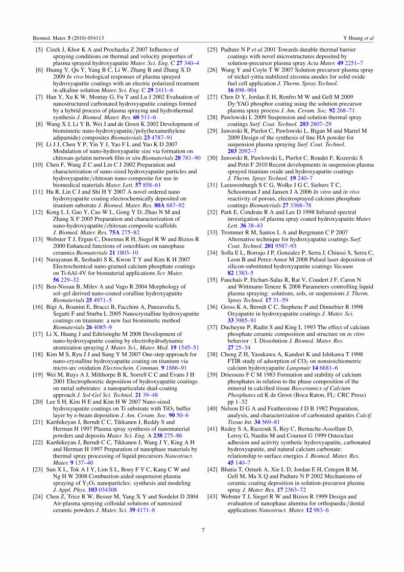
The LPPS coatings also showed much finer splat sizeand crystallite size than those of the APS coatings, whichcould be attributed to the different nature of the LPPS process.Figure 8 shows the schematic diagrams of the APS and LPPSprocesses [42]. In the APS process, after the HA powder wasinjected into the plasma jet, the micron-sized HA powder wasmelted and propelled onto the substrate to form smooth anddense coatings with large splat size and occasionally somemicro-cracks. However, the HA liquid precursor consisted ofneedle-like and rod-like HA particles with a width of 30–50 nmand a length of 100–200 nm. In the LPPS process, the HAliquid precursor was initially broken up into the small dropletsthrough the atomization nozzle. The droplets underwent rapidwater solvent evaporation, further breakup and precipitation ata fine length scale. Then, the precipitate would go throughpyrolysis and melting in the high temperature plasma jet,and finally coatings with ultrafine splats were formed on thesubstrate. It is interesting to see that the nano-structures inthe liquid precursor are somehow retained during the LPPS
5
Biomed. Mater. 5 (2010) 054113 Y Huang et al
Figure 8. The schematic diagrams of the APS and LPPS processes.
process. It is likely due to the suppressed grain growth inthe ultra-short residence time (about milliseconds) during theheat transfer process in the plasma jet and the following rapidcooling upon reaching the substrate. As reported in much ofthe literature, the presence of nano-structured characteristicswould be beneficial to enhance biological efficacy and improveosteoblast adhesion, proliferation and osseointegration[12, 13, 43].
5. Conclusions
A novel LPPS process for synthesizing the nano-structured HAcoatings has been demonstrated in this study. The as-depositedcoatings were mainly composed of the HA phase with nano-scale crystallite size and small splat size. Nano-scale HAparticles were also observed in certain regions of the LPPScoating surface. The formation of nano-structured coatingswas likely due to the suppressed grain growth in the ultra-short residence time during the LPPS process. In addition, theHA coatings deposited by the LPPS process showed a strongpresence of the OH− and CO3
2− groups, which were absent inthe APS coatings. The results suggest that the LPPS process isa promising plasma spraying technique for fabricating nano-structured HA coatings with unique microstructural featuresthat are desirable for enhancing the biological properties ofHA coatings.
Acknowledgments
The authors are grateful to the Analytical & Testing Center,Sichuan University, People’s Republic of China, for theassistance of x-ray diffraction measurement. This studywas supported by grants from the National High TechnologyResearch and Development Program (863 Program) ofPeople’s Republic of China (no 2006AA02A135) and SichuanYouth Science and Technology Foundation of People’sRepublic of China (no 08ZQ026-022).
References
[1] Wang H, Eliaz N, Xiang Z, Hsu H P, Spector M andHobbs L W 2006 Early bone apposition in vivo onplasma-sprayed and electrochemically depositedhydroxyapatite coatings on titanium alloy Biomaterials27 4192–203
[2] McLeod K, Kumar S, Smart R S C, Dutta N, Voelcker N H,Anderson G I and Sekel R 2006 XPS and bioactivity studyof the bisphosphonate pamidronate adsorbed onto plasmasprayed hydroxyapatite coatings Appl. Surf. Sci.253 2644–51
[3] Mohammadi Z, Ziaei-Moayyed A A and Mesgar A S M 2008In vitro dissolution of plasma-sprayed hydroxyapatitecoatings with different characteristics: experimental studyand modeling Biomed. Mater. 3 015006
[4] Yang Y C, Chang E, Hwang B H and Lee S Y 2000 Biaxialresidual stress states of plasma-sprayed hydroxyapatitecoatings on titanium alloy substrate Biomaterials21 1327–37
6
Biomed. Mater. 5 (2010) 054113 Y Huang et al
[5] Cizek J, Khor K A and Prochazka Z 2007 Influence ofspraying conditions on thermal and velocity properties ofplasma sprayed hydroxyapatite Mater. Sci. Eng. C 27 340–4
[6] Huang Y, Qu Y, Yang B C, Li W, Zhang B and Zhang X D2009 In vivo biological responses of plasma sprayedhydroxyapatite coatings with an electric polarized treatmentin alkaline solution Mater. Sci. Eng. C 29 2411–6
[7] Han Y, Xu K W, Montay G, Fu T and Lu J 2002 Evaluation ofnanostructured carbonated hydroxyapatite coatings formedby a hybrid process of plasma spraying and hydrothermalsynthesis J. Biomed. Mater. Res. 60 511–6
[8] Wang X J, Li Y B, Wei J and de Groot K 2002 Development ofbiomimetic nano-hydroxyapatite/poly(hexamethyleneadipamide) composites Biomaterials 23 4787–91
[9] Li J J, Chen Y P, Yin Y J, Yao F L and Yao K D 2007Modulation of nano-hydroxyapatite size via formation onchitosan-gelatin network film in situ Biomaterials 28 781–90
[10] Chen F, Wang Z C and Lin C J 2002 Preparation andcharacterization of nano-sized hydroxyapatite particles andhydroxyapatite/chitosan nano-composite for use inbiomedical materials Mater. Lett. 57 858–61
[11] Hu R, Lin C J and Shi H Y 2007 A novel ordered nanohydroxyapatite coating electrochemically deposited ontitanium substrate J. Biomed. Mater. Res. 80A 687–92
[12] Kong L J, Gao Y, Cao W L, Gong Y D, Zhao N M andZhang X F 2005 Preparation and characterization ofnano-hydroxyapatite/chitosan composite scaffoldsJ. Biomed. Mater. Res. 75A 275–82
[13] Webster T J, Ergun C, Doremus R H, Siegel R W and Bizios R2000 Enhanced functions of osteoblasts on nanophaseceramics Biomaterials 21 1803–10
[14] Narayanan R, Seshadri S K, Kwon T Y and Kim K H 2007Electrochemical nano-grained calcium phosphate coatingson Ti-6Al-4V for biomaterial applications Scr. Mater.56 229–32
[15] Ben-Nissan B, Milev A and Vago R 2004 Morphology ofsol–gel derived nano-coated coralline hydroxyapatiteBiomaterials 25 4971–5
[16] Bigi A, Boanini E, Bracci B, Facchini A, Panzavolta S,Segatti F and Sturba L 2005 Nanocrystalline hydroxyapatitecoatings on titanium: a new fast biomimetic methodBiomaterials 26 4085–9
[17] Li X, Huang J and Edirisinghe M 2008 Development ofnano-hydroxyapatite coating by electrohydrodynamicatomization spraying J. Mater. Sci., Mater. Med. 19 1545–51
[18] Kim M S, Ryu J J and Sung Y M 2007 One-step approach fornano-crystalline hydroxyapatite coating on titanium viamicro-arc oxidation Electrochem. Commun. 9 1886–91
[19] Wei M, Ruys A J, Milthorpe B K, Sorrell C C and Evans J H2001 Electrophoretic deposition of hydroxyapatite coatingson metal substrates: a nanoparticulate dual-coatingapproach J. Sol-Gel Sci. Technol. 21 39–48
[20] Lee S H, Kim H E and Kim H W 2007 Nano-sizedhydroxyapatite coatings on Ti substrate with TiO2 bufferlayer by e-beam deposition J. Am. Ceram. Soc. 90 50–6
[21] Karthikeyan J, Berndt C C, Tikkanen J, Reddy S andHerman H 1997 Plasma spray synthesis of nanomaterialpowders and deposits Mater. Sci. Eng. A 238 275–86
[22] Karthikeyan J, Berndt C C, Tikkanen J, Wang J Y, King A Hand Herman H 1997 Preparation of nanophase materials bythermal spray processing of liquid precursors Nanostruct.Mater. 9 137–40
[23] Sun X L, Tok A I Y, Lim S L, Boey F Y C, Kang C W andNg H W 2008 Combustion-aided suspension plasmaspraying of Y2O3 nanoparticles: synthesis and modelingJ. Appl. Phys. 103 034308
[24] Chen Z, Trice R W, Besser M, Yang X Y and Sordelet D 2004Air-plasma spraying colloidal solutions of nanosizedceramic powders J. Mater. Sci. 39 4171–8
[25] Padture N P et al 2001 Towards durable thermal barriercoatings with novel microstructures deposited bysolution-precursor plasma spray Acta Mater. 49 2251–7
[26] Wang Y and Coyle T W 2007 Solution precursor plasma sprayof nickel-yittia stabilized zirconia anodes for solid oxidefuel cell application J. Therm. Spray Technol.16 898–904
[27] Chen D Y, Jordan E H, Renfro M W and Gell M 2009Dy:YAG phosphor coating using the solution precursorplasma spray process J. Am. Ceram. Soc. 92 268–71
[28] Pawlowski L 2009 Suspension and solution thermal spraycoatings Surf. Coat. Technol. 203 2807–29
[29] Jaworski R, Pierlot C, Pawlowski L, Bigan M and Martel M2009 Design of the synthesis of fine HA powder forsuspension plasma spraying Surf. Coat. Technol.203 2092–7
[30] Jaworski R, Pawlowski L, Pierlot C, Roudet F, Kozerski Sand Petit F 2010 Recent developments in suspension plasmasprayed titanium oxide and hydroxyapatite coatingsJ. Therm. Spray Technol. 19 240–7
[31] Leeuwenburgh S C G, Wolke J G C, Siebers T C,Schoonman J and Jansen J A 2006 In vitro and in vivoreactivity of porous, electrosprayed calcium phosphatecoatings Biomaterials 27 3368–78
[32] Park E, Condrate R A and Lee D 1998 Infrared spectralinvestigation of plasma spray coated hydroxyapatite Mater.Lett. 36 38–43
[33] Trommer R M, Santos L A and Bergmann C P 2007Alternative technique for hydroxyapatite coatings Surf.Coat. Technol. 201 9587–93
[34] Solla E L, Borrajo J P, Gonzalez P, Serra J, Chiussi S, Serra C,Leon B and Perez-Amor M 2008 Pulsed laser deposition ofsilicon-substituted hydroxyapatite coatings Vacuum82 1383–5
[35] Fauchais P, Etchart-Salas R, Rat V, Coudert J F, Caron Nand Wittmann-Teneze K 2008 Parameters controlling liquidplasma spraying: solutions, sols, or suspensions J. Therm.Spray Technol. 17 31–59
[36] Gross K A, Berndt C C, Stephens P and Dinnebier R 1998Oxyapatite in hydroxyapatite coatings J. Mater. Sci.33 3985–91
[37] Ducheyne P, Radin S and King L 1993 The effect of calciumphosphate ceramic composition and structure on in vitrobehavior : I. Dissolution J. Biomed. Mater. Res.27 25–34
[38] Cheng Z H, Yasukawa A, Kandori K and Ishikawa T 1998FTIR study of adsorption of CO2 on nonstoichiometriccalcium hydroxyapatite Langmuir 14 6681–6
[39] Driessens F C M 1983 Formation and stability of calciumphosphates in relation to the phase composition of themineral in calcified tissue Bioceramics of CalciumPhosphates ed K de Groot (Boca Raton, FL: CRC Press)pp 1–32
[40] Nelson D G A and Featherstone J D B 1982 Preparation,analysis, and characterization of carbonated apatites Calcif.Tissue Int. 34 569–81
[41] Redey S A, Razzouk S, Rey C, Bernache-Assollant D,Leroy G, Nardin M and Cournot G 1999 Osteoclastadhesion and activity synthetic hydroxyapatite, carbonatedhydroxyapatite, and natural calcium carbonate:relationship to surface energies J. Biomed. Mater. Res.45 140–7
[42] Bhatia T, Ozturk A, Xie L D, Jordan E H, Cetegen B M,Gell M, Ma X Q and Padture N P 2002 Mechanisms ofceramic coating deposition in solution-precursor plasmaspray J. Mater. Res. 17 2363–72
[43] Webster T J, Siegel R W and Bizios R 1999 Design andevaluation of nanophase alumina for orthopaedic/dentalapplications Nanostruct. Mater. 12 983–6
7