chapter1 introductory tutorials| 1truespace3d.free.fr/manual/ch1_introtutorials.pdf · chapter1...
TRANSCRIPT

Chapter1 Introductory Tutorials| 1
Chapter 1 INTRODUCTORY TUTORIALS .........................................................................................2
1.1 Polygon Edit in Workspace View .........................................................................................2
1.2 NURBS Editing in Model View .............................................................................................7
1.3 Creating a Mechanical Part (Model View) .......................................................................... 11
1.4 The Magic Ring Primitive Manipulator (Model View) ......................................................... 15
1.5 The Selector Cage (Model View) ........................................................................................ 19
1.6 Mixed Editing in Model and Workspace Views ................................................................... 22
1.7 Creating Behaviors Using Link Editor (Workspace View) ..................................................... 27
1.81 Bridge Video ................................................................................................................... 30
1.82 Interface Video ............................................................................................................... 31
1.83 Setting Video .................................................................................................................. 32

Chapter1 Introductory Tutorials| 2
Chapter 1 INTRODUCTORY TUTORIALS
1.1 Polygon Edit in Workspace View
Step 1: In the Default layout, drop a Simple Cube object from the Base Objects library into the 3D Workspace
View.
Step 2: Right-click the cube to enter Point Edit mode or use the pick by paint method from the toolbar. Make
sure you set selection to face, and left-click inside one of the side faces to select it. (When selected, it will be
highlighted green)
Encircle the view around the cube using green semicircle on the View widget, and left-click on the opposing
face while holding the CTRL key to add it to the selection.

Chapter1 Introductory Tutorials| 3
On the Point Edit toolbar, click the Sweep tool. After both faces are swept, scale them down by dragging the
scale part of Point Edit widget, holding both mouse buttons.
Step 3: Now select the two top faces, sweep them, and scale them down, using the same steps as above.

Chapter1 Introductory Tutorials| 4
Step 4: Click the Sweep icon a few more times. Notice that the new extrusions inherit and continue the alterations
you made in the previous step.
Step 5: Select Paint Selection and select all front facing polygons. Now click twice on Add One Layer from
SS (located on the lower left toolbar by default) to smooth the front part of the edited object using
subdivision surface tool.

Chapter1 Introductory Tutorials| 5
Step 6: Select Edge selection and select the center bottom edge in front. Drag the mouse outward from the
subdivided face to form the nose of the emerging spaceship.
Finished Space Ship

Chapter1 Introductory Tutorials| 6
Introductory Tutorial: Workspace Point Edit: Spaceship
Video link

Chapter1 Introductory Tutorials| 7
1.2 NURBS Editing in Model View
Step 1: From Model View in Default layout, open the Material Library , and select the SolidCubes material.
Draw a medium-sized NURBS cylinder (from the toolbar to the left of the Model window).
Steps 2 & 3: Right-click the NURBS cylinder to enter edit mode. Left-click to select the top circle curve. Use the
selection box control to scale the circle smaller and move it slightly down.

Chapter1 Introductory Tutorials| 8
Steps 4 & 5: From the NURBS context edit menu, select Draw Trimming Curve . Draw a simple closed curve
on the surface of the cylinder. Select the Extrude from Edge tool.
Steps 6 & 7: Pull the yellow handle to offset the trimmed patch slightly. Exit edit mode by selecting the Object
tool to see resulting surface better. Right-click the cylinder to enter the edit mode again. Select the top edge of
the extruded trim patch, and pull it away from the adjacent surface.

Chapter1 Introductory Tutorials| 9
Steps 8: Select the Blend tool (from the toolbar at the bottom of the Model window), and then select both curves
on the extruded patch and adjacent surface. Adjust the blend handles to get a smoother blend. Enter edit mode
again, select a control vertex on the bottom circle. Right-click on the control vertex again to enter CV edit
context. Adjust the vertical yellow handle to add curvature to the side of the teapot.
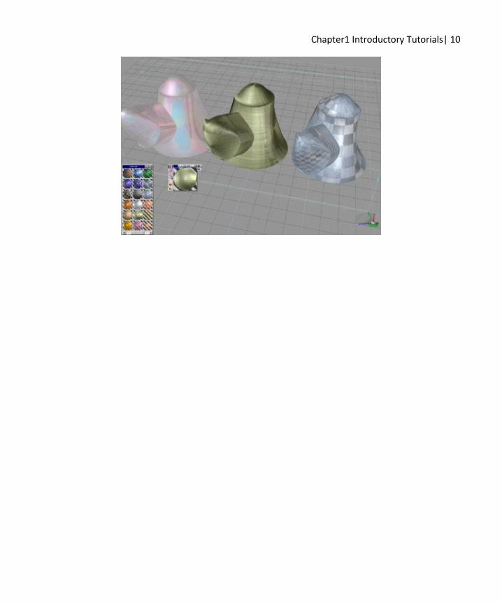
Step 9: Copy the resulting teapot two times and paint two copies with different materials. Glue all three of them
together and select the Render Object option. Not bad for a few minutes’ work!
Chapter1 Introductory Tutorials| 10

Chapter1 Introductory Tutorials| 11
1.3 Creating a Mechanical Part (Model View)
Step 1: Select the Cube tool and click in two places to create two cubes. With one cube selected, activate
the Object Union tool, and click the other cube to Boolean union them into a single object.
Step 2: Right-click on the cube assembly to bring up the point edit tools. Select the Add Edges tool and
connect the matching corners of the two cubes. Faces are created as they are defined by four sides. You now
have a solid object that you can perform other operations on.
Step 3: Create a custom cube by activating the Cube tool, left-clicking and dragging a square, and without
releasing the left mouse button, right-clicking and dragging the square to create a tall rectangle. Use the
Object Move tool to move the rectangle so that it intersects the first object as below. Press CTRL+C to
create a copy of the rectangle, and drag it to the other end of the assembly.
Step 4: Right-click the Object Union tool, and uncheck Delete Edges. Move the bottom face up inside the
first object using the selector control, and Boolean union them together. Boolean subtract the custom
cube from the other end.

Chapter1 Introductory Tutorials| 12
Step 5: An easy way to add a similar piece of geometry is to use the Polygon Bevel tool. Rotate your view
using the green base of the View Control to see the bottom of the object. Activate the Polygon Bevel tool,
and then move your mouse cursor over the bottom face under the Boolean joined geometry. As you move
across the face, a new face will appear inside the original one. When it is about half the size of the original
face, left-click once to “set” it. Use the Sweep tool to sweep it downward once, and then use the selector
cage to adjust the distance.
Step 6: Use the Sweep tool and the selector box to sweep and adjust the distance and size of the front face.

Chapter1 Introductory Tutorials| 13
Step 7: Right-click the object, and select the Add Edges tool again. Add two new edges at the locations
indicated in the image below. Connect the new edges with the Add Edges tool to form a span.
Step 8: Click on the Add SubDivision Level tool three times tool to smooth out the object.

Chapter1 Introductory Tutorials| 14
Step 9: Drag and drop the material labeled “Rough” from the material library, and render the object using the
Render Object tool.
We now have a weather-beaten mechanical part that took minutes to create.

Chapter1 Introductory Tutorials| 15
1.4 The Magic Ring Primitive Manipulator (Model View)
One way to start off a project is with a 3D polyhedron primitive shape. A variety of these are found in the
primitive toolbar..
A click on one will activate the tool and put you in “Creation” mode. Let’s select the cube primitive to start out.
Notice the small yellow box tagged to the cursor as you hover over the grid. Left-click on the grid and a basic
polygon primitive will appear. Notice the multi colored ring attached to the object. This is the “Magic Ring”. It
actually allows you to create an infinite number of primitive shapes from each of the basic polygon primitives. By
alternately left or right-click dragging in different directions on one of the four colors in the ring you can control
all the parameters and possible shapes of a primitive. A right-click on the active tool icon will bring up all the
numerical entry counter parts of the Magic Ring.
A left-click drag side to side on the blue diamond (not shown) will rotate the basic cube around. A right-click drag
side to side on the blue diamond will change the number of longitudinal faces around the sides of the primitive.

Chapter1 Introductory Tutorials| 16
Draw a cube Add sides
A left-click drag side to side on the tan corners of the ring will adjust the spherical rounding of the primitive
corners. A left-click drag up and down on one side of red part will adjust the conic angle of the primitive and open
the hole inside the primitive.
Round the edges Make a Hole in the middle
Horizontally left-clicking and dragging will change the angle of the primitive vertical wall. Vertically
left-clicking and dragging will shorten the wall length.

Chapter1 Introductory Tutorials| 17
Tilt the wall Shorten the wall
Horizontally right-clicking and dragging on blue diamond will increase further the number of segments in the
primitive wall .
As you can quickly see by combining all these controls in different combinations, an immense number of
primitive shapes are right at your fingertips through the wonder of the magic ring.

Chapter1 Introductory Tutorials| 18
Once you like the look of your primitive you can click elsewhere on the grid and start making changes from the
point you left off with the previous one. Once satisfied you can leave it as is and create as many as you like or,
with a right-click on the grid, tapping the space bar, or clicking on the object tool, you can exit the primitive
creation mode.

Chapter1 Introductory Tutorials| 19
1.5 The Selector Cage (Model View)
When you exit the primitive creation mode, you will notice a blue selector cage around the active object. This is
the key to learning trueSpace. It is the easiest tool to learn and yet one of the most important. The selector cage
controls all aspects of the active object or selection relating to its location, rotation, and scale. A right-click on the
Object tool will bring up the numerical control panel for this manipulator.
Notice as you mouse over the various parts of the selector cage that the activated part turns yellow. It does not take
long to learn the basic functions of the four different parts.
The points of the corners will scale the object proportionately. The sections next to the corners will scale the
object in the direction you drag them or scale the object proportionately when you hold down both mouse buttons
at the same time and drag. The middle sections will move the object in the direction you drag them. The rotation
diamonds in the middle of those will rotate the object around its various axes. As you mouse closer to the
diamonds you will notice that they darken in color to match the axis they will rotate around. Blue is Y, Green is X,
and Red is Z.

Chapter1 Introductory Tutorials| 20
Why is this manipulator the key to learning trueSpace? Within the Modeling View, from the entire object down to
the selection of faces, edges and vertices you will find this same control cage.
You even use it to adjust the UV projections for materials and in the UV editor to position textures exactly on

Chapter1 Introductory Tutorials| 21
faces.
Many of the point edit tools even use it to control the changes they make on the geometry. Once you learn this tool
you will find that you have control over most of the aspects of shape creation in Model View.

Chapter1 Introductory Tutorials| 22
1.6 Mixed Editing in Model and Workspace Views
The real-time live bridge in trueSpace allows you to edit your model in both views with different sets of tools,
while going back and forth between Model and workspace. This provides added flexibility as long as you
remember that some operations may override object construction history. For example, you will lose Player SDS
history after you apply (older) Model View Point edit. Even with this limitation, the number of design scenarios is
greatly expanded with the ability to alternate between both views.
Step 1: Start in Default Layout with Model View open. Draw a cube using a cube tool from the primitives
toolbar.
Step1: Load the cube into Model View
Step 2: Open the “LW materials” library and drag the “grafitiWall” material onto the cube. Select the Cubic UV
Projection icon. Finally, select the QuadDivide icon to subdivide each face of the cube.

Chapter1 Introductory Tutorials| 23
Step2: Cube after material assignment and quad-division
Step 3: Right-click on the cube to enter point edit mode. The cube will become transparent, and Model’s point
edit toolbar will appear. Select and sweep in turn three faces using the Sweep tool from the toolbar. Drag
the swept faces out using center part of blue NAV widget (selector cage).
Step3: Three swept faces (top one was scaled slightly)

Chapter1 Introductory Tutorials| 24
Step 4: Now switch to Player View using the Workspace tab on the title bar.
Step4: Switching to Player View
Step 5: Click twice on the Add One Layer SDS icon on the left side of the Workspace View to add two
SDS layers.

Chapter1 Introductory Tutorials| 25
Step5: SDS tool applied twice
Step 6: Right-click on the smoothed object to enter edit mode. The object becomes transparent, and the
Workspace-side point edit toolbar appears. Select the Add Loop tool and add a horizontal loop on the
main part of edited cube, then scale the new slice up using the small grey cube of the point edit 3D widget.
Step6: SDS loop added and scaled
Step 7: Now switch back to Model View using its tab on the title bar. Open the UV Mapping Editor panel,
select the paint brush, and paint a white pattern into UVE panel. It immediately appears on the 3D model.
Chapter1 Introductory Tutorials| 26
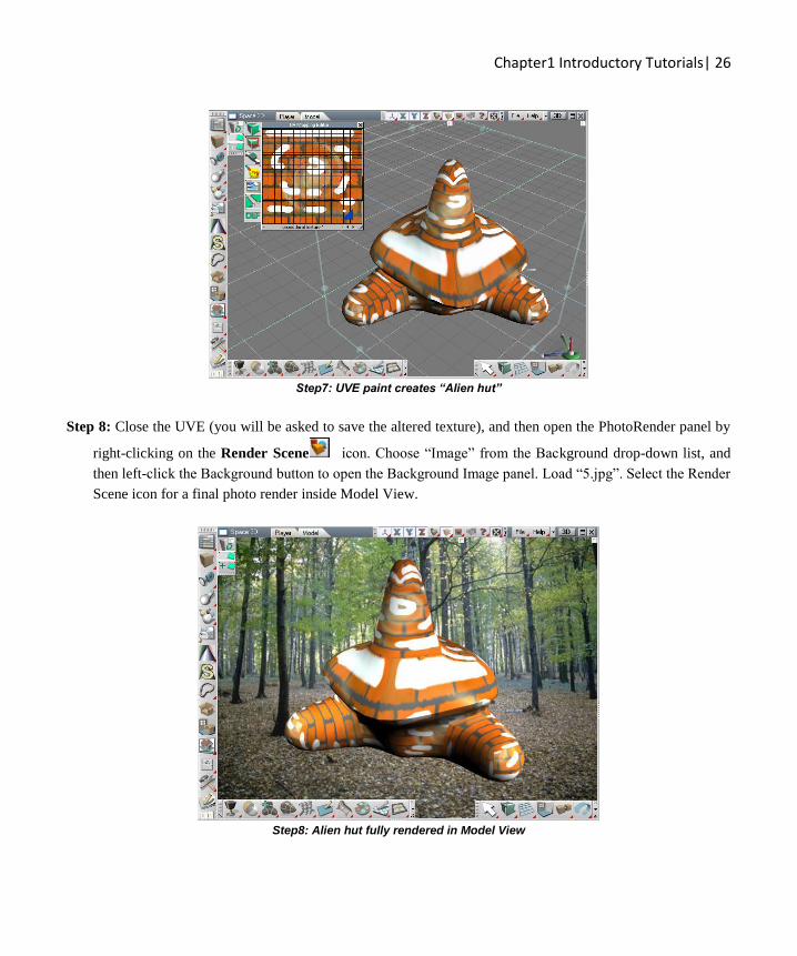
Step7: UVE paint creates “Alien hut”
Step 8: Close the UVE (you will be asked to save the altered texture), and then open the PhotoRender panel by
right-clicking on the Render Scene icon. Choose “Image” from the Background drop-down list, and
then left-click the Background button to open the Background Image panel. Load “5.jpg”. Select the Render
Scene icon for a final photo render inside Model View.
Step8: Alien hut fully rendered in Model View

Chapter1 Introductory Tutorials| 27
1.7 Creating Behaviors Using Link Editor (Workspace View)
This tutorial will teach you how to add a simple but realistic behavior to your models using drag, drop and link
inside the Link Editor. In example below, we will make the propeller spin when the plane moves forward.
Step 1: Start in Default Layout with Player View opened. From the Base library, drag and drop the “Plane” object
into the 3D View. When it appears in Link Editor view, click on its orange triangle to enter it. You should see
3 objects: Propeller, PlaneBody, and Transform
Note: Propeller and PlaneBody are just plain 3D objects. The Transform object glues them together, so if
you move plane, both plane body and plane propeller move together.
Enter the Propeller object by clicking on its orange triangle.
Pict.1: Load the Plane model and enter its propeller object
Step 2: In this step you prepare to replace the 0D joint (identity Transform) with the 1D one. The 1D joint is called

Chapter1 Introductory Tutorials| 28
Rotation Engine and you can find it in Objects/Tutorial objects library. Drag and drop it into the Propeller
object.
Pict.2: Add Rotation Engine object into propeller object
Then open the default aspect of the Transform object. To do this, left-click on the Transform object in Link Editor
and again click on the Default tab.
Pict.3: Select the transform object and switch it to Default aspect.
Since we will be reconnecting some links we need to display them first. To do it choose Developer tab on the Link
Editor.

Chapter1 Introductory Tutorials| 29
Pict.4: Choose Developer aspect
Step 3: The last step is to plug-in the Rotation Engine. Drag and drop all the links from Transform object into
corresponding connectors on the Rotation Engine. It is recommended you start with input connectors (red
ones) and finish with output connectors, so the recommended order would be as follows:
1. Matrix
2. OwnerMatrix
3. ObjMatrix
4. WldMatrix
Pict.5: Move all the links from Transform to Rotation Engine object
We are done! Now, the propeller should rotate when you move the plane object. To test this, click on its wing in
Player view. It should become selected. Then move it. If you want slowdown or speed up the rotation, just adjust
the RotSpeed slider.
Notice that the propeller rotates only when you move the plane forward or backwards. If you uncheck the
ForwardRot attribute, then it will rotate on any movement of plane.

Chapter1 Introductory Tutorials| 30
1.81 Bridge Video
One important aspect of working in trueSpace is the Bridge. In trueSpace, the Bridge acts as a communication
medium between the Workspace and the Model windows. There may be circumstances where utilizing the Bridge
is required, while other times the Bridge is not necessarily required. The ability to turn the Bridge on or off as
required, will benefit your work by saving time and effort.
Introductory Tutorial: Bridge
Video link

Chapter1 Introductory Tutorials| 31
1.82 Interface Video
Within trueSpace, the ability to customize your interface holds great power and potential. Some important aspects
of the interface and how to customize these elements are covered in this tutorial.
Introductory Tutorial: Interface
Video link

Chapter1 Introductory Tutorials| 32
1.83 Setting Video
Each window in trueSpace has settings associated with it. The ability to customize the settings for various
windows in trueSpace, allows you to customize the windows for better workflow or for individual
taste/preference. Many of the important settings are introduced in this tutorial.
Introductory Tutorial: Settings
Video link