chapter 5 – system modeling 1chapter 5 system modeling cs 425 october 18, 2010 ian sommerville,...
TRANSCRIPT
Chapter 5 – System Modeling
1Chapter 5 System modeling
CS 425 October 18, 2010
Ian Sommerville, Software Engineering, 9th Edition
Pearson Education, Addison-Wesley
Note: These are a modified version of Ch 5 slides available from the author’s site http://www.cs.st-andrews.ac.uk/~ifs/Books/SE9/
Topics covered
Context models
Process models
Interaction models
Structural models
Behavioral models
Model-driven engineering
2Chapter 5 System modeling
System modeling
System modeling is the process of developing abstract models of a system, with each model presenting a different view or perspective of that system.
System modeling has now come to mean representing a system using some kind of graphical notation, which is now almost always based on notations in the Unified Modeling Language (UML).
System modelling helps the analyst to understand the functionality of the system and models are used to communicate with customers.
3Chapter 5 System modeling
Existing and planned system models
Models of the existing system are used during requirements engineering. They help clarify what the existing system does and can be used as a basis for discussing its strengths and weaknesses. These then lead to requirements for the new system.
Models of the new system are used during requirements engineering to help explain the proposed requirements to other system stakeholders. Engineers use these models to discuss design proposals and to document the system for implementation.
In a model-driven engineering process, it is possible to generate a complete or partial system implementation from the system model.
4Chapter 5 System modeling
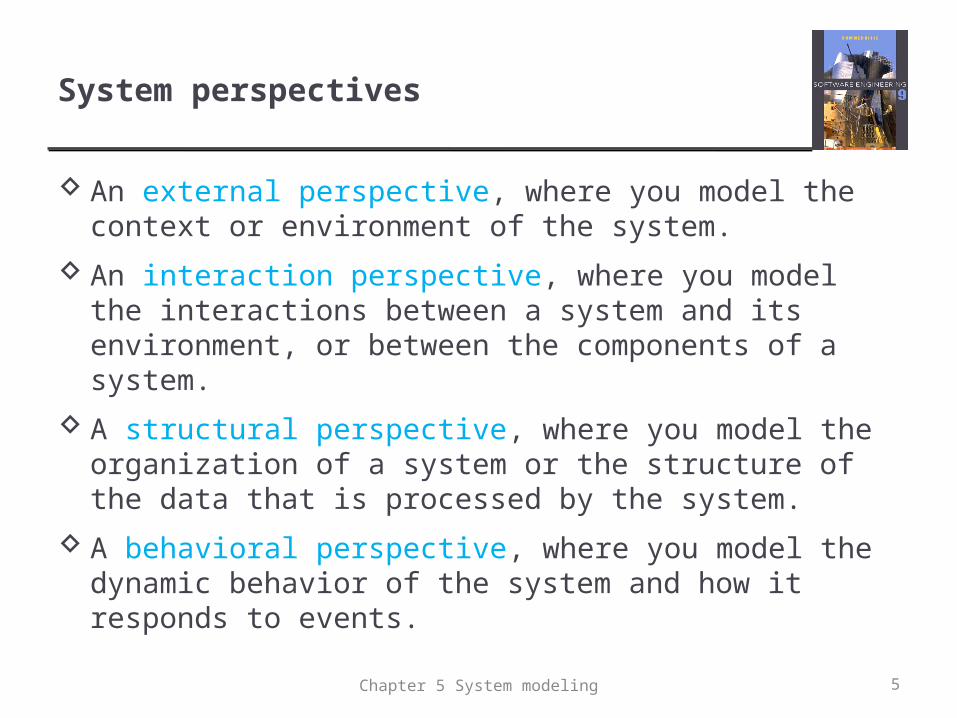
System perspectives
An external perspective, where you model the context or environment of the system.
An interaction perspective, where you model the interactions between a system and its environment, or between the components of a system.
A structural perspective, where you model the organization of a system or the structure of the data that is processed by the system.
A behavioral perspective, where you model the dynamic behavior of the system and how it responds to events.
5Chapter 5 System modeling
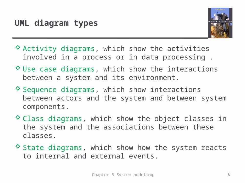
UML diagram types
Activity diagrams, which show the activities involved in a process or in data processing .
Use case diagrams, which show the interactions between a system and its environment.
Sequence diagrams, which show interactions between actors and the system and between system components.
Class diagrams, which show the object classes in the system and the associations between these classes.
State diagrams, which show how the system reacts to internal and external events.
6Chapter 5 System modeling
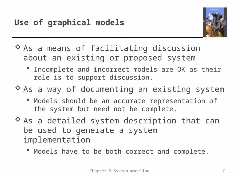
Use of graphical models
As a means of facilitating discussion about an existing or proposed system Incomplete and incorrect models are OK as their role is to
support discussion.
As a way of documenting an existing system Models should be an accurate representation of the system but
need not be complete.
As a detailed system description that can be used to generate a system implementation Models have to be both correct and complete.
7Chapter 5 System modeling
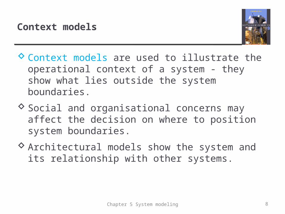
Context models
Context models are used to illustrate the operational context of a system - they show what lies outside the system boundaries.
Social and organisational concerns may affect the decision on where to position system boundaries.
Architectural models show the system and its relationship with other systems.
8Chapter 5 System modeling
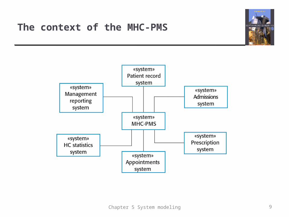
The context of the MHC-PMS
9Chapter 5 System modeling
Process perspective
Context models simply show the other systems in the environment, not how the system being developed is used in that environment.
Process models reveal how the system being developed is used in broader business processes.
UML activity diagrams may be used to define business process models.
10Chapter 5 System modeling
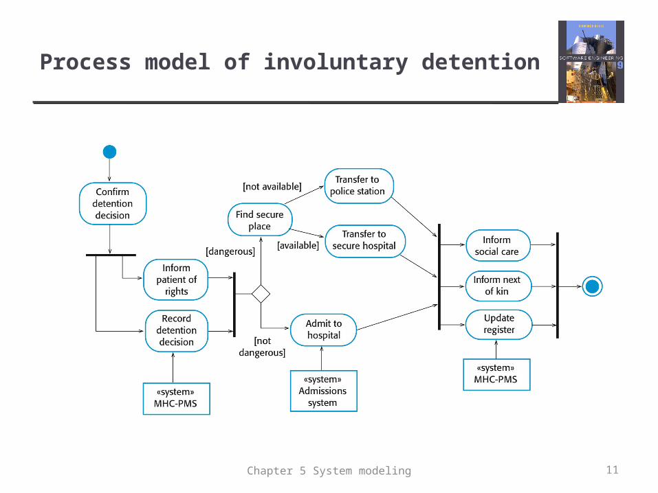
Process model of involuntary detention
11Chapter 5 System modeling
Interaction models
Modeling user interaction is important as it helps to identify user requirements.
Modeling system-to-system interaction highlights the communication problems that may arise.
Modeling component interaction helps us understand if a proposed system structure is likely to deliver the required system performance and dependability.
Use case diagrams and sequence diagrams may be used for interaction modeling.
12Chapter 5 System modeling
Use case modeling
Use cases were developed originally to support requirements elicitation and now are incorporated into the UML.
Each use case represents a discrete task that involves external interaction with a system.
Actors in a use case may be people, time, or other systems.
13Chapter 5 System modeling
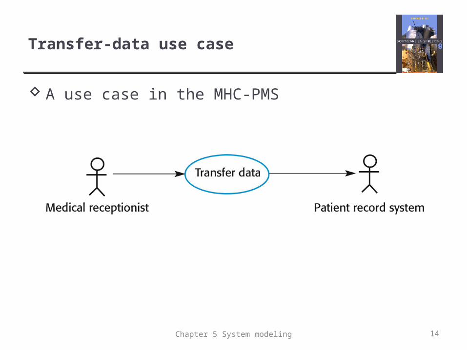
Transfer-data use case
A use case in the MHC-PMS
14Chapter 5 System modeling
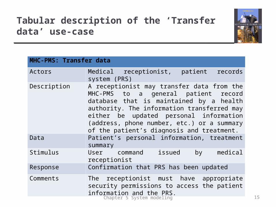
Tabular description of the ‘Transfer data’ use-case
MHC-PMS: Transfer data
Actors Medical receptionist, patient records system (PRS)
Description A receptionist may transfer data from the MHC-PMS to a general patient record database that is maintained by a health authority. The information transferred may either be updated personal information (address, phone number, etc.) or a summary of the patient’s diagnosis and treatment.
Data Patient’s personal information, treatment summary
Stimulus User command issued by medical receptionist
Response Confirmation that PRS has been updated
Comments The receptionist must have appropriate security permissions to access the patient information and the PRS.
15Chapter 5 System modeling
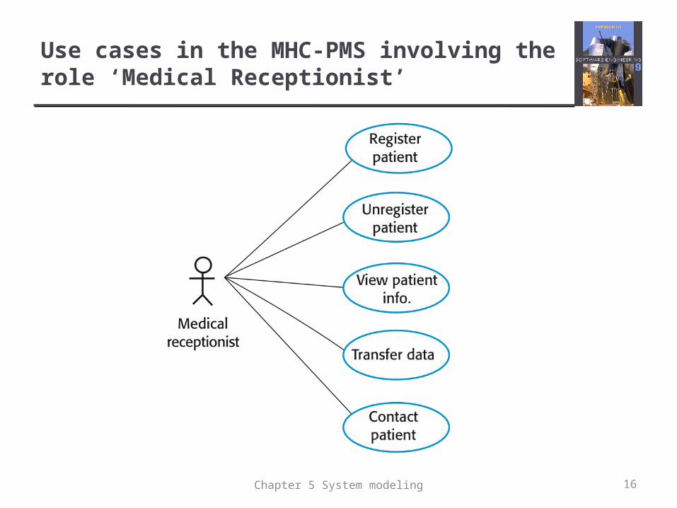
Use cases in the MHC-PMS involving the role ‘Medical Receptionist’
16Chapter 5 System modeling
Sequence diagrams
Sequence diagrams are part of the UML and are used to model the interactions between the actors and the objects within a system.
A sequence diagram shows the sequence of interactions that take place during a particular use case or use case instance.
The objects and actors involved are listed along the top of the diagram, with a dotted line drawn vertically from these.
Interactions between objects are indicated by annotated arrows.
17Chapter 5 System modeling
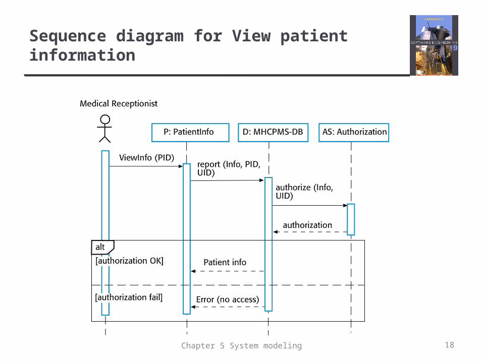
Sequence diagram for View patient information
18Chapter 5 System modeling
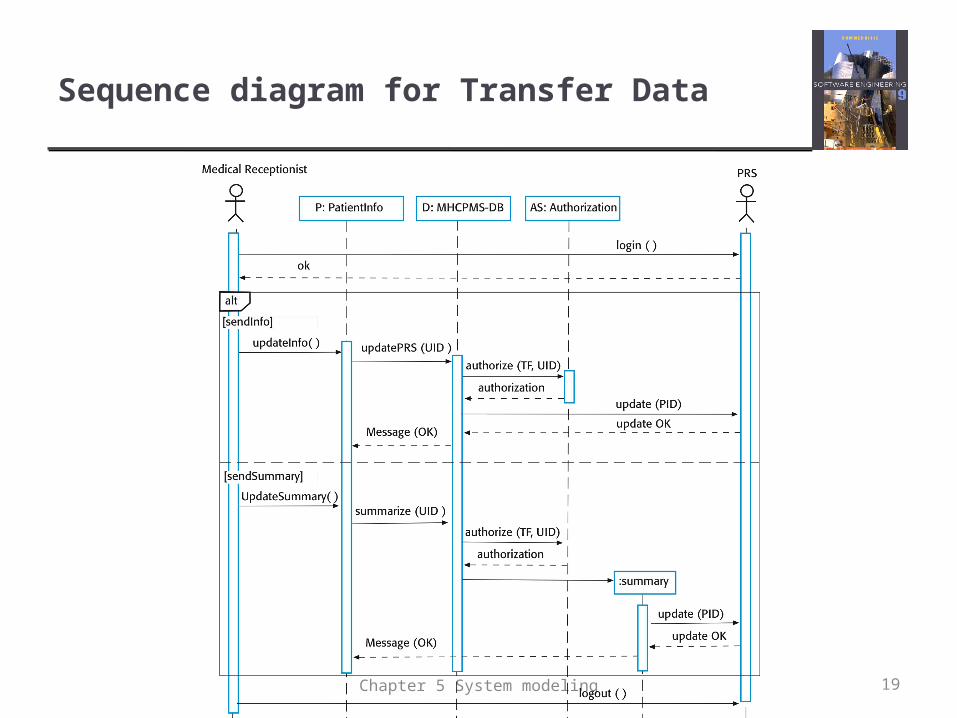
Sequence diagram for Transfer Data
19Chapter 5 System modeling
Class diagrams
Class diagrams are used when developing an object-oriented system model to show the classes in a system and the associations between these classes.
An object class can be thought of as a general definition of one kind of system object.
An association is a link between classes that indicates that there is some relationship between these classes.
When you are developing models during the early stages of the software engineering process, objects represent something in the real world, such as a patient, a prescription, doctor, etc.
20Chapter 5 System modeling
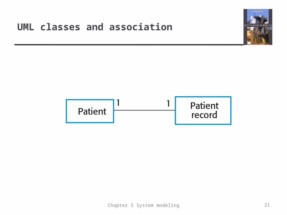
UML classes and association
21Chapter 5 System modeling
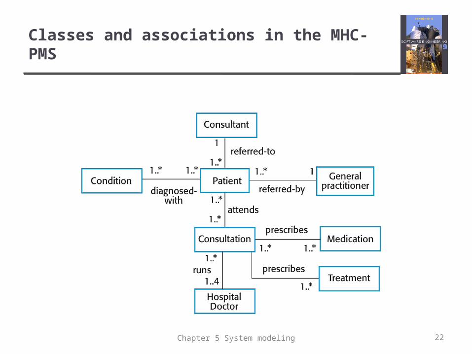
Classes and associations in the MHC-PMS
22Chapter 5 System modeling
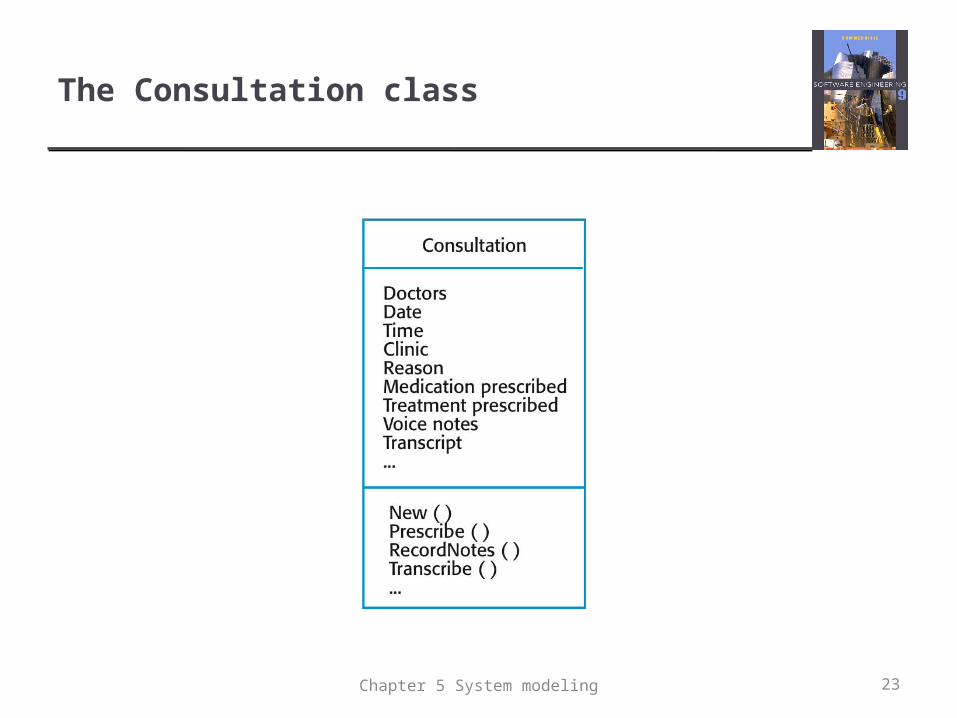
The Consultation class
23Chapter 5 System modeling
Generalization
Generalization is an everyday technique that we use to manage complexity.
Rather than learn the detailed characteristics of every entity that we experience, we place these entities in more general classes (animals, cars, houses, etc.) and learn the characteristics of these classes.
This allows us to infer that different members of these classes have some common characteristics e.g. squirrels and rats are rodents.
Chapter 5 System modeling 24
Generalization
In modeling systems, it is often useful to examine the classes in a system to see if there is scope for generalization. If changes are proposed, then you do not have to look at all classes in the system to see if they are affected by the change.
In object-oriented languages, such as Java, generalization is implemented using the class inheritance mechanisms built into the language.
In a generalization, the attributes and operations associated with higher-level classes are also associated with the lower-level classes.
The lower-level classes are subclasses inherit the attributes and operations from their superclasses. These lower-level classes then add more specific attributes and operations.
Chapter 5 System modeling 25
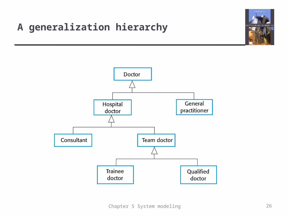
A generalization hierarchy
26Chapter 5 System modeling
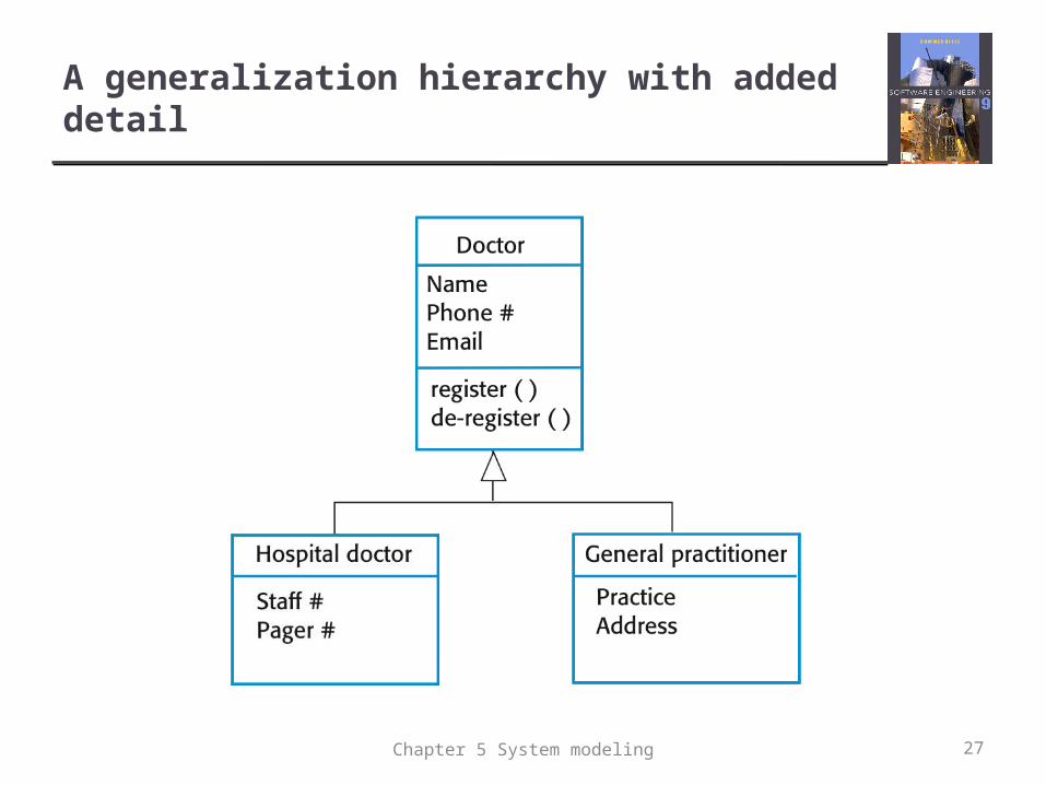
A generalization hierarchy with added detail
27Chapter 5 System modeling
Object class aggregation models
An aggregation model shows how classes that are collections are composed of other classes.
Aggregation models are similar to the part-of relationship in semantic data models.
28Chapter 5 System modeling
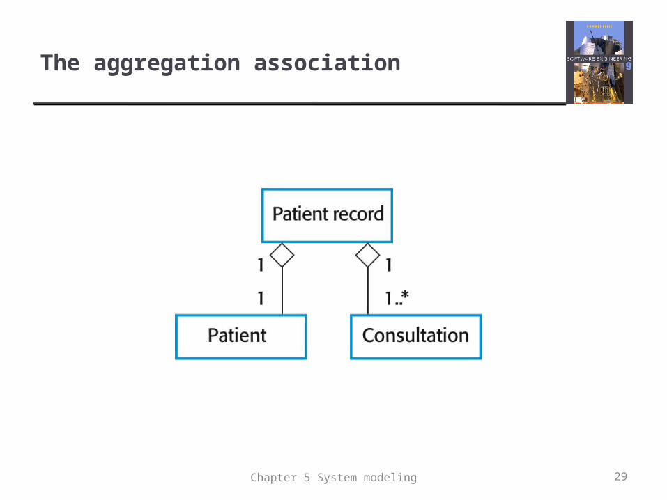
The aggregation association
29Chapter 5 System modeling
Behavioral models
Behavioral models are models of the dynamic behavior of a system as it is executing. They show what happens or what is supposed to happen when a system responds to a stimulus from its environment.
You can think of these stimuli as being of two types: Data Some data arrives that has to be processed by the system. Events Some event happens that triggers system processing.
Events may have associated data, although this is not always the case.
30Chapter 5 System modeling

Data-driven modeling
Many business systems are data-processing systems that are primarily driven by data. They are controlled by the data input to the system, with relatively little external event processing.
Data-driven models show the sequence of actions involved in processing input data and generating an associated output.
They are particularly useful during the analysis of requirements as they can be used to show end-to-end processing in a system.
31Chapter 5 System modeling
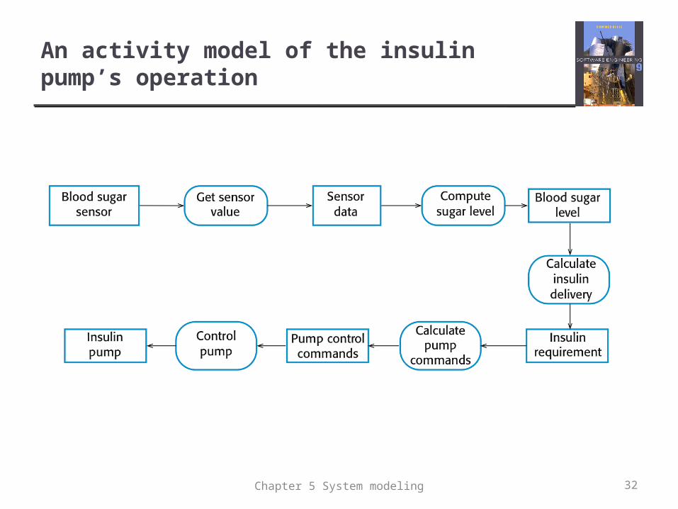
An activity model of the insulin pump’s operation
32Chapter 5 System modeling
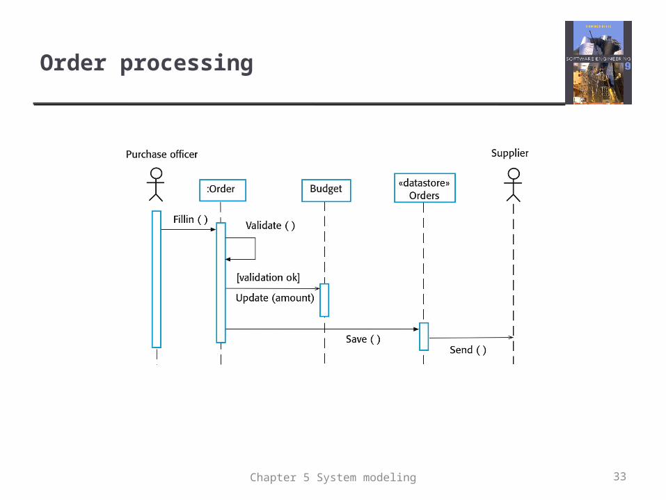
Order processing
33Chapter 5 System modeling
Event-driven modeling
Real-time systems are often event-driven, with minimal data processing. For example, a landline phone switching system responds to events such as ‘receiver off hook’ by generating a dial tone.
Event-driven modeling shows how a system responds to external and internal events.
It is based on the assumption that a system has a finite number of states and that events (stimuli) may cause a transition from one state to another.
Chapter 5 System modeling 34
State machine models
These model the behaviour of the system in response to external and internal events.
They show the system’s responses to stimuli so are often used for modelling real-time systems.
State machine models show system states as nodes and events as arcs between these nodes. When an event occurs, the system moves from one state to another.
Statecharts are an integral part of the UML and are used to represent state machine models.
35Chapter 5 System modeling
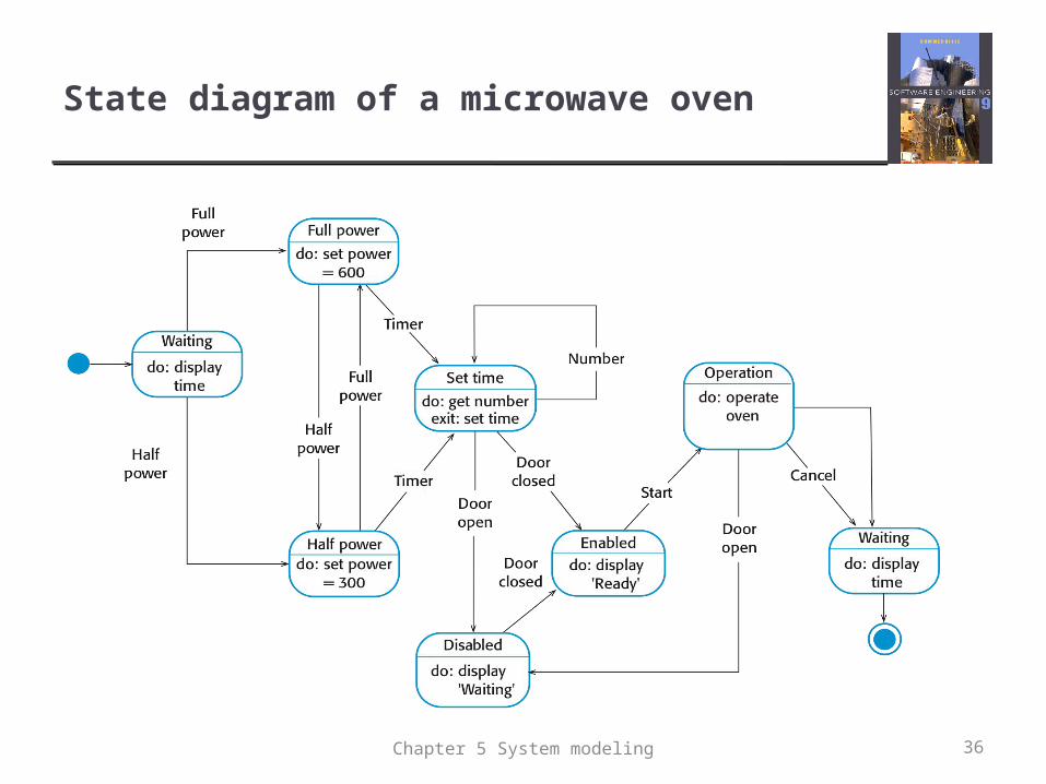
State diagram of a microwave oven
36Chapter 5 System modeling
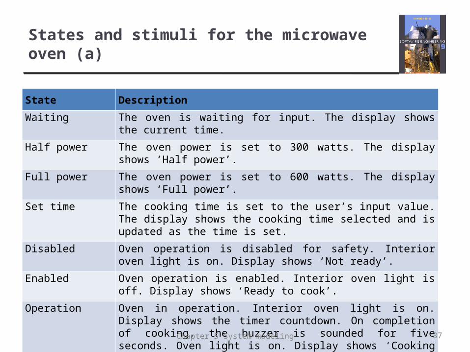
States and stimuli for the microwave oven (a)
State Description
Waiting The oven is waiting for input. The display shows the current time.
Half power The oven power is set to 300 watts. The display shows ‘Half power’.
Full power The oven power is set to 600 watts. The display shows ‘Full power’.
Set time The cooking time is set to the user’s input value. The display shows the cooking time selected and is updated as the time is set.
Disabled Oven operation is disabled for safety. Interior oven light is on. Display shows ‘Not ready’.
Enabled Oven operation is enabled. Interior oven light is off. Display shows ‘Ready to cook’.
Operation Oven in operation. Interior oven light is on. Display shows the timer countdown. On completion of cooking, the buzzer is sounded for five seconds. Oven light is on. Display shows ‘Cooking complete’ while buzzer is sounding.
37Chapter 5 System modeling
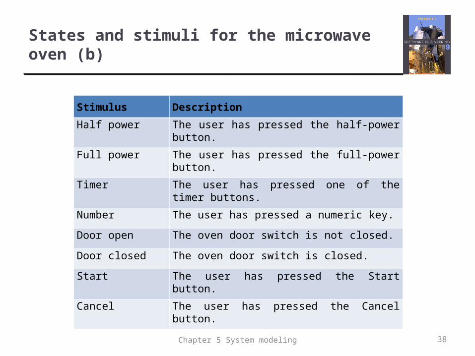
States and stimuli for the microwave oven (b)
Stimulus Description
Half power The user has pressed the half-power button.
Full power The user has pressed the full-power button.
Timer The user has pressed one of the timer buttons.
Number The user has pressed a numeric key.
Door open The oven door switch is not closed.
Door closed The oven door switch is closed.
Start The user has pressed the Start button.
Cancel The user has pressed the Cancel button.
38Chapter 5 System modeling
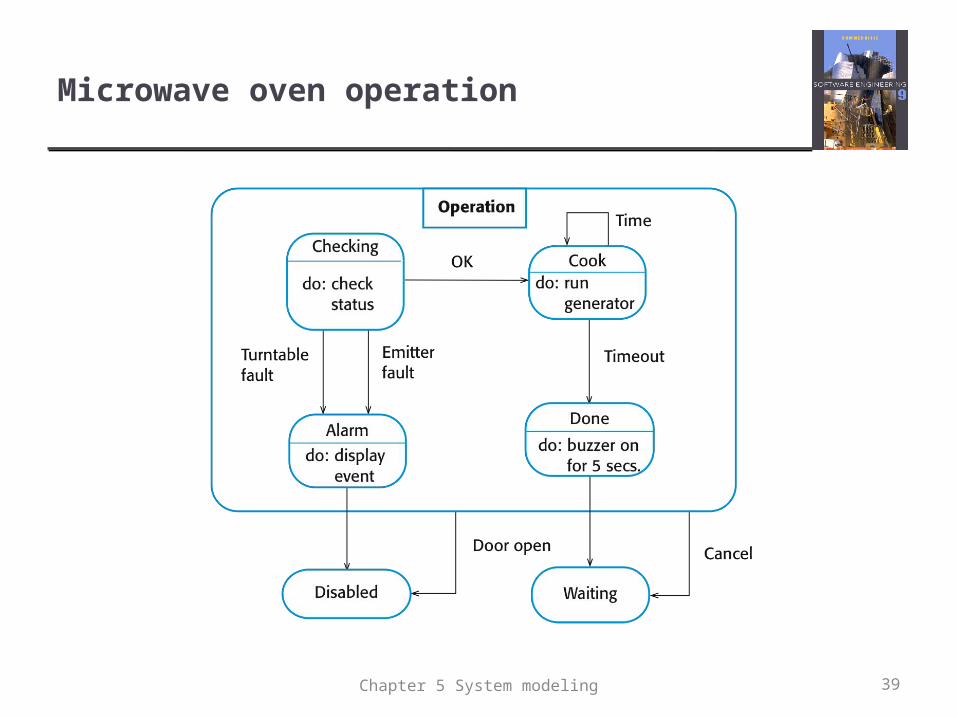
Microwave oven operation
39Chapter 5 System modeling
Model-driven engineering
Model-driven engineering (MDE) is an approach to software development where models rather than programs are the principal outputs of the development process.
The programs that execute on a hardware/software platform are then generated automatically from the models.
Proponents of MDE argue that this raises the level of abstraction in software engineering so that engineers no longer have to be concerned with programming language details or the specifics of execution platforms.
Chapter 5 System modeling 40
Usage of model-driven engineering
Model-driven engineering is still at an early stage of development, and it is unclear whether or not it will have a significant effect on software engineering practice.
Pros Allows systems to be considered at higher levels of abstraction Generating code automatically means that it is cheaper to adapt
systems to new platforms.
Cons Models for abstraction and not necessarily right for
implementation. Savings from generating code may be outweighed by the costs
of developing translators for new platforms.
Chapter 5 System modeling 41
Model driven architecture
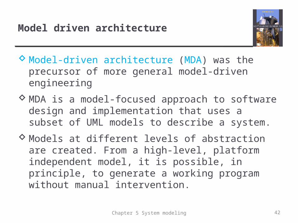
Model-driven architecture (MDA) was the precursor of more general model-driven engineering
MDA is a model-focused approach to software design and implementation that uses a subset of UML models to describe a system.
Models at different levels of abstraction are created. From a high-level, platform independent model, it is possible, in principle, to generate a working program without manual intervention.
Chapter 5 System modeling 42
Types of model
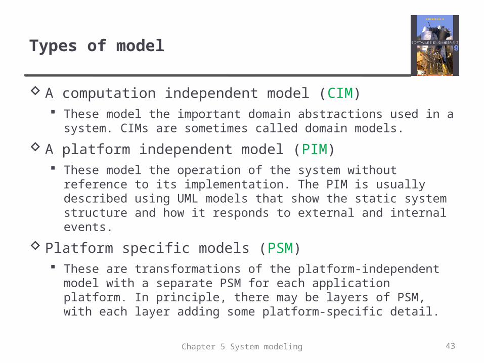
A computation independent model (CIM) These model the important domain abstractions used in a system.
CIMs are sometimes called domain models.
A platform independent model (PIM) These model the operation of the system without reference to its
implementation. The PIM is usually described using UML models that show the static system structure and how it responds to external and internal events.
Platform specific models (PSM) These are transformations of the platform-independent model with
a separate PSM for each application platform. In principle, there may be layers of PSM, with each layer adding some platform-specific detail.
Chapter 5 System modeling 43
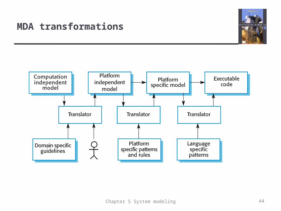
MDA transformations
44Chapter 5 System modeling
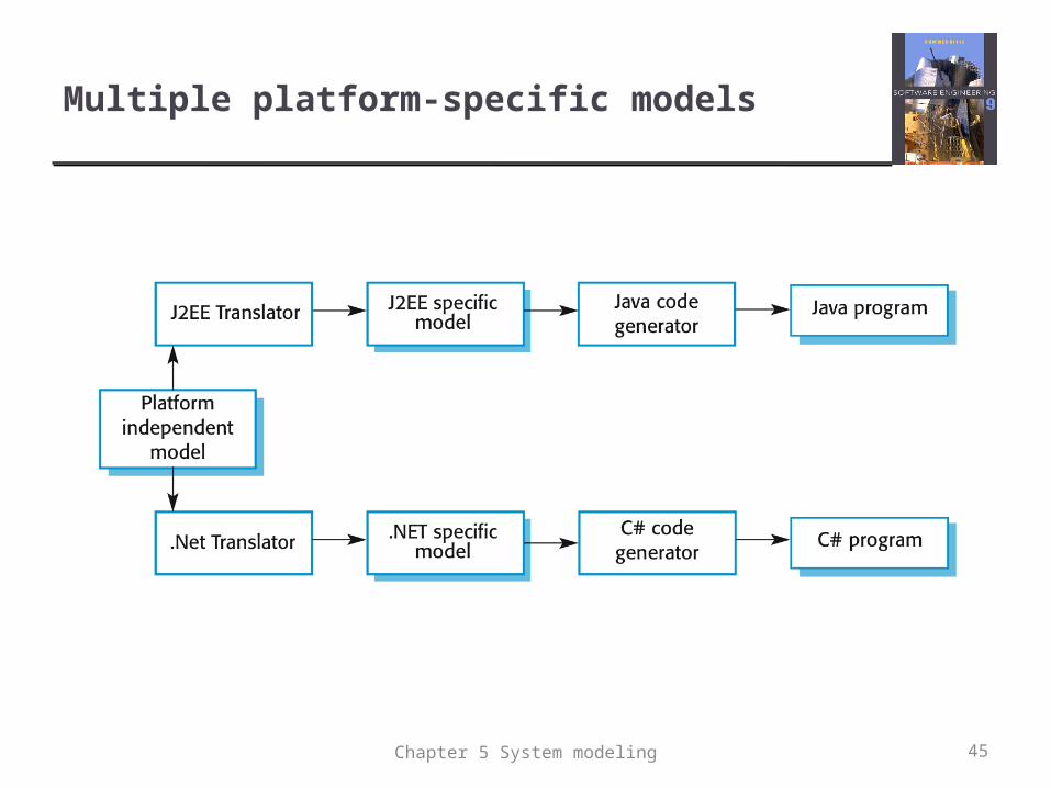
Multiple platform-specific models
45Chapter 5 System modeling
Agile methods and MDA
The developers of MDA claim that it is intended to support an iterative approach to development and so can be used within agile methods.
The notion of extensive up-front modeling contradicts the fundamental ideas in the agile manifesto and I suspect that few agile developers feel comfortable with model-driven engineering.
If transformations can be completely automated and a complete program generated from a PIM, then, in principle, MDA could be used in an agile development process as no separate coding would be required.
Chapter 5 System modeling 46
Executable UML
The fundamental notion behind model-driven engineering is that completely automated transformation of models to code should be possible.
This is possible using a subset of UML 2, called Executable UML or xUML.
Chapter 5 System modeling 47
Features of executable UML
To create an executable subset of UML, the number of model types has therefore been dramatically reduced to these 3 key types: Domain models that identify the principal concerns in a system.
They are defined using UML class diagrams and include objects, attributes and associations.
Class models in which classes are defined, along with their attributes and operations.
State models in which a state diagram is associated with each class and is used to describe the life cycle of the class.
The dynamic behavior of the system may be specified declaratively using the object constraint language (OCL), or may be expressed using UML’s action language.
Chapter 5 System modeling 48
Key points
A model is an abstract view of a system that ignores system details. Complementary system models can be developed to show the system’s context, interactions, structure and behavior.
Context models show how a system that is being modeled is positioned in an environment with other systems and processes.
Use case diagrams and sequence diagrams are used to describe the interactions between users and systems in the system being designed. Use cases describe interactions between a system and external actors; sequence diagrams add more information to these by showing interactions between system objects.
Structural models show the organization and architecture of a system. Class diagrams are used to define the static structure of classes in a system and their associations.
Chapter 5 System modeling 49
Key points
Behavioral models are used to describe the dynamic behavior of an executing system. This behavior can be modeled from the perspective of the data processed by the system, or by the events that stimulate responses from a system.
Activity diagrams may be used to model the processing of data, where each activity represents one process step.
State diagrams are used to model a system’s behavior in response to internal or external events.
Model-driven engineering is an approach to software development in which a system is represented as a set of models that can be automatically transformed to executable code.
Chapter 5 System modeling 50