chapter-5 environmental management · pdf filedraft eia report for narmada thermal power ......
TRANSCRIPT
Draft EIA report for Narmada Thermal Power Limited 5-1
Chapter-5 Environmental Management Plan
5.0 INTRODUCTION
An environmental management plan (EMP) is a management framework for reducing
environmental impacts and improving organizational performance. EMP provide
organizations, a structured approach for managing environmental and regulatory
responsibilities to improve overall environmental performance, including areas not
subject to regulation such as unregulated risk, resource conservation, and energy
efficiency etc.
The project details provided by proponent and the pre-project (baseline) environmental
status monitored through field surveys by M/s Detox Corporation Ltd. team during
summer season (March to May 2011) were the basis to evaluate the impacts on all
individual components of environment due to the proposed project activities.
In view of the above, project proponent shall maintain the specifications/details/data as
provided for preparation of this report or may try to improve further towards betterment
of environmental protection during various phases of implementation of proposed
project. Proposed development consists of land procurement, construction phase and
operation phases. The environmental management plan relevant to these phases is
delineated in the following sections:
5.1 CONSTRUCTION PHASE
The construction phase impacts would be mainly due to civil works such as site
preparation comprising heavy earthmoving, site grading, RCC foundations; construction
material and machinery transportation, fabrication and erection etc..
The construction phase impacts will be temporary and localized phenomenon except the
change in the land use pattern. The environment management to be implemented during
the construction phase is as delineated below:
The top layer soil which is excavated during site leveling shall be sold to contractor or
shall be disposed off in the low lying area instead of accumulating the same on the road
or the premises area.
Temporary huts of the construction labours shall be arranged within the project
boundary.
The site grading, partial level rising as required at project site shall be planned
keeping in view the natural drainage around the project site.
Draft EIA report for Narmada Thermal Power Limited 5-2
The vehicles used for transportation of construction material shall be certified within
valid PUC.
The trucks carrying cement and sand should be covered in order to prevent the
fugitive emissions due to material handling.
Temporary shed shall be developed in order to store the construction material inside
the project premises.
The machinery used for construction purpose shall be properly maintained and
serviced.
It should be ensured that diesel powered vehicles and construction machinery are
properly maintained to minimize the exhaust emissions as well as noise generation
The construction debris generated shall be properly stored in the shed and later
should be used for leveling of low lying area and road construction.
Regular water sprinkling shall be done in the storage area and within the plant
boundary for dust suppression.
Though the effect of noise on the nearby inhabitants due to construction activity will
be insignificant as per the proposed plot plan, noise prone activities should be
restricted to the extent possible during day time in order to have minimum noise
impact during night time.
Onsite workers should be strictly instructed to use noise protection devices like
earmuffs in noise prone area.
Hazardous materials such as lubricating oil, compressed gases, paints and varnishes
are required during construction phase which should be stored properly as per the
safety regulations at isolated places.
Accidental spillages of oil from construction equipment and storage sites should be
prevented.
The fuel used for the machines should be of good quality.
Proper arrangement shall be made to prevent to washout of construction material
during the monsoon season. Temporary shed of brick should be constructed during
the monsoon season for the storage of construction material.
Proper storm water management system shall be integrated in design phase and
civil works shall be carried out accordingly at project site.
Once the construction phase is completed, proper clean up of the plant area shall be
done and the construction debris and the other waste shall be disposed off at the
low lying areas.
Draft EIA report for Narmada Thermal Power Limited 5-3
5.2 OPERATION PHASE
Based on the impacts discussed in the chapter-4 due to the upcoming power plant
project on the air environment, water environment, land environment, noise
environment, Biodiversity and socio economic environment a detailed environment
management plan is proposed in order to mitigate the impacts identified.
The various types of pollution from the power plant are categorized under the following
types:
• Air pollution.
• Water pollution.
• Solid waste/ hazardous waste generation
• Noise pollution.
• Bio ecological environment / Green belt
The various proposed pollution control systems are described in the following sections.
5.3 AIR ENVIRONMENT
In order to control the flue gas emission two stack each with height of 130 m has been
envisaged with boiler at the site. This height of the stack will be adequate for the proper
dispersion of the pollutant.
The stack height for the proposed boiler was decided based on the below mentioned
formula.
H=14 Q 0.3 Where Q is SO2 emission in kg/hr.
As per the emission details calculated on the basis of gas composition, SO2 content in
exhaust was calculated.
Sulphur content in coal is considered as 1 %.
Accordingly SO2 emission is 866.5 kg/hr
Stack height required = 14 * Q 0.3 Where Q is SO2 emission rate in kg/hr
Total Stack height required = 106.52 m
Stack height provided = 130 m
Hence the stack height provided for the boiler is adequate
High efficiency Electrostatic Precipitators (ESP) having efficiency not less than 99.8% will
be installed for each boiler to control the emission of particles in fly ash. The ESP will be
designed to limit the particulate emission to 50 mg/Nm3 as per prevailing CPCB
Draft EIA report for Narmada Thermal Power Limited 5-4
standards. / SPCB Standards. To facilitate wider dispersion of pollutants one chimney will
be provided for each unit and sampling port(s) will be provided for continuous online
monitoring. Access doors will also be provided for facilitating inspection. The technical
detail of ESP is given in chapter 2, section 2.8.2, page no. 2-15.
Dust Extraction & Dust Suppression systems will be provided in Coal & Ash handling
systems.
5.3.1 Control of Fugitive Emissions
Following area/ operation has been identified from which fugitive emission may occur.
i) Loading/ Unloading of coal at port and project site.
ii) Transportation from port to plant
iii) Stacking of coal/ Coal storage area.
iv) Transfer of coal from storage yard to screening, crusher house and coal storage bin.
v) Fugitive emission from fly ash storage area.
5.3.1.1 Coal handling
Detail coal handling system is discussed in chapter 2, section 2.3.2, page 2-2.
Following environment management system will be adopted to control fugitive
emissions.
i) Unloading of coal by dumpers will be carried out with proper care avoiding dropping
of the materials from height. Also the material will be moist by sprinkling water while
unloading at the project site as well as the port.
ii) Transportation of coal from port to plant shall be done by dumpers. In case of non
availability of dumpers the same shall be done in trucks covered with tarpaulin
sheets. The coal shall be moist in order to prevent the fugitive emissions during
transportation.
iii) Due to the blowing wind there shall be fugitive emissions in the coal storage area.
The same shall be prevented by regular water sprinkling in the storage area. The
storage area shall be covered from all the four sides by wall or wind barricading shall
be provided by sheets.
iv) Crushing and screening operation should be carried out in enclosed area. Centralized
de dusting facility (collection hood and suction arrangement) followed by de dusting
unit like bag filter and final discharge of emission done through a stack in order to
control fugitive particulate matter emissions. Particulate matter emission level in the
Draft EIA report for Narmada Thermal Power Limited 5-5
stack should not exceed 50 mg/Nm3. Water sprinkling arrangement should be
provided at raw material heaps and on land around the crushing and screening units.
v) Work area including the roads surrounding the plant shall be asphalted or concreted.
vi) Enclosure should be provided for belt conveyors and transfer points of belt
conveyors.
The above enclosures will be rigid and permanent and fitted with self closing doors and
close fitting entrances and exits, where conveyors pass through the enclosures. Flexible
covers shall be installed at entry and exit of the conveyor to the enclosures, minimizing
the gaps around the conveyors.
5.3.1.2 Fly ash handling
Control techniques for fugitive dust emission from ash storage pond, involves watering,
chemical stabilization, reduction of surface wind speed with windbreaks or source
enclosures. Watering, the most common and, generally, least expensive method, provide
only temporary dust control.
The use of chemicals or treat-exposed surfaces provides longer dust suppression, but will
be costly. Effective control of fugitive emissions will be achieved by either of the
following ways, in isolation or in combination.
i) By providing a containment enclosures to the dust-generating source (thereby
isolating/containing the source from wind currents) in order to contain the
airborne emissions within the enclosures. The same shall be achieved by
providing a wall at the periphery of the ash pond/ loading unloading area/ ash
silo. The height of the wall will be decided during detail engineering.
ii) By suppressing the dust by spraying water so that the dust settles down & remain
suppressed till the moisture evaporates. The detailed design of dust suppression
system for the ash pond will be taken up during engineering.
The SPM in the vicinity of the ash storage pond shall be maintained below
statutory norms.
The details fly has handling system is discussed in upcoming sections.
Water Sprinklers
Type of sprinkler system envisaged for control of dust nuisance in the ash and coal
storage area with its specifications is as given below
No. of sprinklers : 132
Pipe diameter : 5 inch
Draft EIA report for Narmada Thermal Power Limited 5-6
5.4 WATER ENVIRONMENT
5.4.1 Water Conservation steps
The first step toward the management of water environment would be conservation of
the raw water. Proper step shall be taken to conserve the water from the operation
phase, apart from the reuse and recycle of the wastewater generated .Conservation of
raw water will also facilitate the mitigation of wastewater generation. As far as possible
boiler blow-down and steam condensate will be recovered and reused for floor wash and
other non-process applications. By adopting these measures it is estimated that 2% of
the total water consumption.
Conservation of raw water will also facilitate the mitigation of waste water generation.
• Storm water drainage network shall be designed
• Faucets uses are of low water consumption type.
• W.C, Flush and Urinal Flush valve are of low water consumption type
• Waste Water generated will be reused within the premises
Liquid effluents generated from the TPP would consist of water pre-treatment plant
waste, routine floor washing waste, sanitary waste, D.M plant reject etc.
The clarifier sludge would be separately taken to a sludge treatment plant for removal
of solids.
5.4.2 Rain Water Harvesting
As the project site is located in water rich area it is not practically feasible to recharge
the ground water by rain water harvesting system. Hence it is not envisaged for the
proposed project.
Storm water drainage has been constructed to lead the rain water to common collection
pond and the collected water shall be reused in the process.
5.4.3 Waste water Generated
Water balance diagram of water consumption and wastewater generation, treatment and
disposal is given in chapter 4, section 4.4, page 4-11.
The waste water generated as blow down from cooling tower and boiler, rejects from
different process shall be collected in the neutralization pit and after dilution will be
reused within the plant for green belt development, dust handling area and plant
washing.
Oily wastes will be processed through oil separators to trap oil from the effluents
emanating from the Oil Handling Area.
Draft EIA report for Narmada Thermal Power Limited 5-7
The waste water generated shall be recycle back in the system and reused as sprinkling
on road, coal storage area, ash storage area and green belt development.
The quantity of waste water to be reused is as given below
Green belt : 1317.88 m3/day
Ash conditioning/ coal and dust handling : 70 m3/day
Washing - Oil unloading area : 20 m3/day
Plant washing : 20 m3/day
The total land available for the above usage is 74 acres.
The domestic waste water will be treated in sewage treatment plant.
5.5 SOLID/ HAZARD WASTE GENERATION
The used oil generated will be temporarily stored in drums in isolated covered room and
later will be disposed off through registered recycler. Discarded containers generated will
also be stored in the isolated area and later sold to approved recyclers. ETP sludge and
used resins shall be in covered isolated area and later disposed off at approved land fill
site.
The membership certificate of TSDF site for the disposal of hazardous waste generated is
attached herewith as annexure 5.
Direct manual handling of waste will be avoided. The person handling the waste will be
equipped with hand gloves resistant to the waste, respiratory mask and goggles.
Record of the hazardous waste generated shall be maintained as per the Hazardous
waste rules 2008 in the prescribed format and the same shall be regularly submitted to
statutory authority. Prior to dispatch of the waste to the recycler company representative
will keep a check on the valid authorization and approval obtained by the recycler from
Central Pollution Control board.
5.5.1 Fly Ash management
The fly ash generated will be collected and stored in fly ash silos.
Regular water sprinkling shall be done in the fly ash storage area.
The fly ash generated shall be transported in dumpers from generation point to
the final disposal point
The fly ash generated will be sold to brick/cement manufacturers and the MoU
with the near by brick manufacturer is attached as annexure 6.
Draft EIA report for Narmada Thermal Power Limited 5-8
5.5.1.1 Ash handling system
The ash handling system envisages wet extraction and disposal of bottom ash & dry
extraction for fly ash. The fly ash will be extracted in dry form from the electrostatic
precipitator hoppers, economizer & air heater hoppers and stack hopper and transported
to storage silo as a measure for promoting ash utilization.
System capacities furnished below have been arrived at considering coal consumption at
MCR condition as 103 TPH for 1 x 135 MW units and ash content as 40% for Indian coal.
a) MCR coal firing rate per unit : 103 TPH
b) Rate of ash generation for design of equipment [40% for
coal]
: 41.2 TPH
c) Rate of bottom ash formation [20% of (b)] : 8 TPH
d) Bottom ash removal capacity considered on continuous
removal basis ( 1.5 x item C)
: 12 TPH
e) Rate of fly ash formation (80% of (b)) : 33 TPH
f) Total fly ash formed in 8 hours per unit : 264 T
g) Time required for removal of fly ash generated in 8 hours : 4 hours & 30 min
h) Fly ash system capacity required [(f) / (g)] : 58.6 TPH
i) Fly ash removal system capacity selected : 60 TPH
Bottom ash handling system capacity of 12 TPH for each unit will be based on an
average ash generation of 8 TPH per unit to enable removal of ash collected considering
outages in downstream system. Fly ash handling system capacity for each unit will be
based on an ash generation of 33 TPH per unit to enable removal of ash collected in 8
hours of ash collected in bottom ash hoppers in 4 ½ hours.
Dense phase type system
Fly ash resulting from the combustion of coal in the boiler gets collected in economizer
hopper, air heater hopper, ESP hoppers etc. For collecting fly ash in dry form, the
system will be designed such that, the fly ash and conveying air mixture will be
conveyed to storage silo with bag filters. Once in eight (8) hours shift, the fly ash will be
sequentially extracted from these hoppers. The fly ash handling system will be designed
to collect ash in dry form in fly ash silos through pneumatic pressure conveying system,
as described below:
Draft EIA report for Narmada Thermal Power Limited 5-9
The fly ash collected in hoppers will be gravity fed into individual ash vessels provided
below each hoppers. Each ash vessel will be provided with one (1) manual operated
knife type gate valve, one (1) stainless steel expansion bellow, one (1) pneumatic
operated ash intake valve (dome type) etc.
On initiation of fly ash removal cycle, ash inlet valve on upstream of ash vessel will be
opened and fly ash will be fed by gravity into the ash vessel after which the inlet valve
will close. On closure of ash inlet valve, the conveying compressed air will be supplied to
the ash vessel (by opening the air inlet valve). On reaching the pre-determined
conveying pressure in the vessel, the fly ash will be conveyed to fly ash silos with the
help of compressed air through transport piping. MS ERW pipe work conforming to
IS:1239 (H) will be provided for transporting ash collected in ESP hoppers to either of
the fly ash silos. The conveying air will be vented to atmosphere through bag filters
mounted on top of silo.
The conveying air required for the system will be drawn from conveying air compressors.
The instrument air required for the operation of various valves will be drawn from the
plant instrument air service.
A vent filter will be mounted on the silo to reduce the environmental pollution. The
system controls will be such that, it will be possible to stop unloading fly ash from any
hopper or to bypass any hopper, as desired by the operator. Fly ash removal of each unit
at full load will take about four hours & fifteen minutes in a shift of eight (8) hours for
ash collected in various hoppers while firing worst coal.
5.5.1.2 Disposal of Ash
Disposal of Fly Ash from Silo
Dry fly ash from the air pre-heater, stack hopper, Eco. hoppers and ESP hoppers will be
collected in the fly ash storage silo. The storage silos two nos will be designed to have a
storage capacity of 750 tonnes each which caters for twenty four hours of fly ash
generation. The dry fly ash collected in the storage silo will be normally disposed in the
dry conditioned form. The fly ash will be unloaded in dry form through rotary feeder and
double shaft paddle type dust conditioners to open trucks for utilization of fly ash. The fly
ash conveying air will be vented to the atmosphere through vent bag filter to mitigate
the environmental pollution. Fly ash silos will be provided with three (3) outlets - one for
disposal of ash in conditioned form into open trucks through ash conditioner and other
for disposal of fly ash in dry form to closed container trucks through telescopic unloading
spout.
Draft EIA report for Narmada Thermal Power Limited 5-10
Disposal of Bottom ash
The bottom ash will be disposed in ash pond. Bottom ash collected in silo of capacity 350
tonnes (about 48 hrs’ storage capacity) will be transported thru’ trucks to the ash dyke.
Provisions in the silo will be as that of fly ash silo. Efforts will be made to dispose the ash
to landfill use etc.
5.5.1.3 Ash Disposal Area
An ash dyke in an area of 42 acres will be installed mainly to dispose off bottom ash in
case the off take by other agencies is delayed due to unforeseen reasons. The ash pond
dyke will be of maximum 15m height. Suitable impervious lining for the ash pond will be
provided to prevent leaching of ash from the pond. Water Sprinklers will be provided to
contain fugitive dust emission. Efforts will be made to grow plantation over the dyke.
5.6 CLEANER PRODUCTION
The following initiatives shall be taken under cleaner production for the proposed
project:
Control of Fugitive Emissions at the raw material and fly ash handling side
Complete utilization of fly ash for cement/ brick manufacturing units.
Near complete recovery and recycling of the fines in the materials handling train
by increasing availability of the dust capturing devices, better operational control
and preventive maintenance of the dust capturing devices
Reuse of the non utilizable vitrified material and wastes for filling of low lying land
in the plant premises for preparation of land for expansion
Use of solar energy will be made wherever possible. Food preparation will be
done in canteen using solar cookers. Electricity to light canteen, parking zone,
office area will be generated vide solar energy. Solar heater will be installed at
company guest house.
For the proposed project initially 653.34 KL/day of water shall be required in
cooling tower but in the later stages the water requirement will decrease due to
use of recycle water. Only make up water will be required. Hence there will be
conservation of water.
The term cycles of concentration (COC) compares the level of solids of the
recirculating cooling tower to the level of solids of the original raw make up
water. The circulating water will have five times the solids concentration than that
of the make up water, thus the cycles will be 5.
The following measures shall be taken in the plant under cleaner production activities.
Draft EIA report for Narmada Thermal Power Limited 5-11
Table 5.1: Action plan for implementation of CP
Sr. CP Issue/Measure
Action Plan
1 Raw material handling & preparation area
Automated water spraying system. Work
zone should be hard paved to reduce
dusting due to transportation of vehicles
2 Near complete recovery of fines in the
materials handling train at
a. Crushing and screening of coal (Materials
circuits)
b. Raw material feeding point.
c. Coal injection point to boiler
d. Cooler discharge circuit
a. Pulse jet bag filter
b. Pulse jet bag filter
c. Pulse jet bag filter
d. Pulse jet bag filter
3 Material transfer points and conveyer belts Localized loss of cladding due to constant
repairs and local modification of the
conveyer routes and chutes to be reclad
and the exhaust ventilation system to be
made re effective
4 Sprinkler system in the stock yard and
provision of water fogging at the time of
truck loading/unloading operations
Feasibility and basic engineering for the
sprinkler system being carried out
5 Better house keeping To be implemented
6 Waste water generation 100 % waste water generated in the form
of DM reject, boiler blow down and
cooling tower blow down is reused within
the plant premises for gardening, dust
suppression and cooling purpose
7 Fly ash Sold to near by brick/cement
manufacturers
Draft EIA report for Narmada Thermal Power Limited 5-12
5.7 ENVIRONMENT MANAGEMENT PLAN FOR LAND/ SOIL ENVIRONMENT
Proper care shall be taken in order to protect the land from the pollution caused due to
spillage of oil and other waste material.
Proper dyke are provided in order to prevent the spillage of oil directly on ground.
Waste water generated shall be treated below statutory norms before using for
gardening and plantation.
Domestic waste will be treated in Sewage treatment plant.
Dry paper waste shall be collected in bins instead of throwing on land.
5.8 NOISE ENVIRONMENT
Manufacturers and suppliers of major equipments like compressors, boilers and turbine
should be asked to take required measures for minimizing the noise levels generated by
the machines i.e. using noise absorbing material for enclosures or using appropriate
design/technology for fabricating/assembling machines.
The major noise sources in the proposed plant are the Steam turbine and the
compressors. The equipment hall is planned to be designed in such a way that the
possible leak of sound from the hall to the outside area is architecturally sealed and the
radiators (the air coolers) are proposed to be installed with variable frequency drive
motors which will operate at a very low speed and hence shall have very less noise.
The compressors will be placed in closed building to prevent the dispersion of noise in
the surrounding region. The gas compressor and turbine will be the major noise
generating equipment and in order to restrict the combine effect of noise from both
these sources, they are place apart from each other. Silencers will be installed at noise
generating sources.
The operators working in the high-noise areas shall be strictly instructed to use ear-
muffs/ear-plugs and shift timings will be adjusted as per the Factory Act. Green belt
shall be developed to attenuate noise and the extent of green belt shall be as per CPCB
guidelines. Noise barriers in the form of trees will be grown around the plant boundary.
Personnel working near the vibrating machinery in different units shall be provided with
well-designed vibration resistant hand gloves/ foot wears and suitable Personal
Protection Equipments (PPEs).Vibration generating sources and their platforms shall be
maintained properly to minimize vibrations and related impacts. Training of personnel is
recommended to create awareness about the damaging effects of vibrations; if PPEs are
not used as regular practice while on duty. Regular noise monitoring on weekly basis will
Draft EIA report for Narmada Thermal Power Limited 5-13
be carried out at the noise generating sources mainly at the compressor building and the
turbine room as well as the entry - exit gates of the plant.
Greenbelt development within and around the plant shall be undertaken through
plantation of appropriate native species. Plantation apart from improving the aesthetics,
would act as sink for gaseous pollutants and masking for noise generated at the project.
5.9 GREEN BELT DEVELOPMENT
In order to reduce the air pollutants concentration and to reduce the wind blown dust to
escape from the project premises to the near by localities and to resist the noise
generated due to plant activity and as source to uptake the wastewater generated to
some extent, it is recommended to develop green belt around the periphery of the plant,
surrounding the coal storage yard, Ash dyke, and along the road side. There won’t be
any relocation of existing trees in the near vicinity of the project site as far as possible.
The total green belt area of about 42 acres has been demarcated for the proposed
project in the layout. In addition to development of green belt within the premises the
company is committed to carry out aforestation and biodiversity improvement
programme in the surrounding villages.
5.9.1 Recommended Plants for Green Belt Development
Greenbelts are an effective mode of control of air pollution, where green plants form a
surface capable of absorbing air pollutants and forming a sink of pollutants. Leaves with
their vast area in a tree crown, sorbs pollutants on their surface, thus effectively reduce
pollutant concentration in the ambient air. Often the adsorbed pollutants are
incorporated in the metabolic pathway and the air is purified. Plants grown to function as
pollution sink are collectively referred as greenbelts.
An important aspect of a greenbelt is that the plants are living organism with their varied
tolerance limit towards the air pollutants. A green belt is effective as a pollutant sink only
within the tolerance limit of constituent plants.
Apart from function as pollution sink, greenbelt would provide other benefit like aesthetic
improvement of the area and providing suitable habitats for birds and animals.
5.9.2 Guidelines for plantation
The plant species identified for greenbelt development shall be planted using pitting
technique. The pit size will be either 45 cm x 45 cm x 45 cm or 60 cm x 60 cm x 60 cm.
Bigger pit size will be considered at marginal and poor quality soil. Soil used for filling
the pit should be mixed with well decomposed farm yard manure or sewage sludge at
the rate of 2.5 kg (on dry weight basis) and 3.6 kg (on dry weight basis) for 45cm x 45
cm x 45 cm and 60 cm x 60 cm x 60 cm size pits respectively. The filling of soil should
Draft EIA report for Narmada Thermal Power Limited 5-14
be completed at least 5-10 days before actual plantation. Healthy sapling of identified
species should be planted in each pit with the commencement of monsoon. Provision for
regular and liberal watering during the summer period during the commissioning stage
of the plant will be arranged from the local available resources. After the proposed
thermal power plant became operational, treated waste water shall be available for
watering the planted trees and shrubs. The authorities responsible for plantation will also
make adequate measures for the protection of the saplings.
While making choices of plant species for cultivation in green belts, weightage has been
given to the natural native species, bio climatic condition, plants which can be grown as
per normal horticultural practices. Plant species identified for greenbelt development,
considering the bio-climatic and soil condition are listed in Table 5.2.
5.9.3 Selection of plants for Greenbelts:
The main limitation for plants to function as scavenger of pollutants are, plant’s
interaction to air pollutants, sensitivity to pollutants, climatic conditions and soil
characteristics. While making choice of plants species for cultivation in green belts, due
consideration has to be given to the natural factor of bio- climate. Xerophytes plants are
not necessarily good for greenbelts; they with their sunken stomata can withstand
pollution by avoidance but are poor absorber of pollutants.
Character of plants mainly considered for affecting absorption of pollutant gases and
removal of dust particle are as follows.
• For absorption of Gases:
Tolerance towards pollutants in question, at concentration, that is not too high to be
instantaneously lethal
Longer duration of foliage
Freely exposed foliage
Adequate height of crown
Openness of foliage in canopy
Big leaves( long and broad laminar surface)
Large number of stomatal apertures
• For Removal of Suspended Particular matter
1. Height and spread of crown.
2. Leaves supported on firm petiole
3. Abundance of surface on bark and foliage
Draft EIA report for Narmada Thermal Power Limited 5-15
4. Roughness of bark
5. Abundance of axillary hairs
6. Hairs or scales on laminar surface
7. Protected Stomata
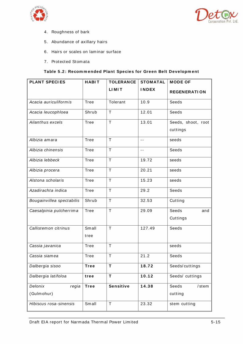
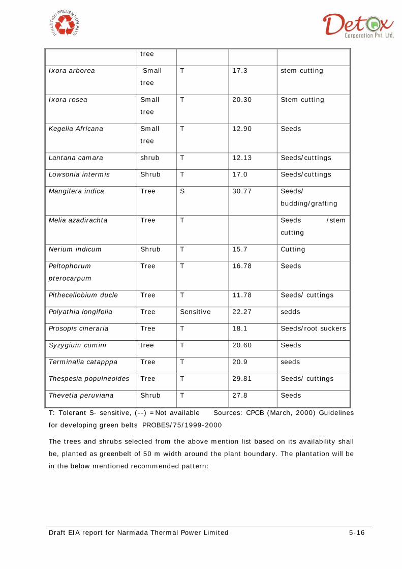
Table 5.2: Recommended Plant Species for Green Belt Development
PLANT SPECIES HABIT TOLERANCE
LIMIT
STOMATAL
INDEX
MODE OF
REGENERATION
Acacia auriculiformis Tree Tolerant 10.9 Seeds
Acacia leucophloea Shrub T 12.01 Seeds
Ailanthus excels Tree T 13.01 Seeds, shoot, root
cuttings
Albizia amara Tree T -- seeds
Albizia chinensis Tree T -- Seeds
Albizia lebbeck Tree T 19.72 seeds
Albizia procera Tree T 20.21 seeds
Alstona scholaris Tree T 15.23 seeds
Azadirachta indica Tree T 29.2 Seeds
Bougainvillea spectabilis Shrub T 32.53 Cutting
Caesalpinia pulcherrima Tree T 29.09 Seeds and
Cuttings
Callistemon citrinus Small
tree
T 127.49 Seeds
Cassia javanica Tree T seeds
Cassia siamea Tree T 21.2 Seeds
Dalbergia sisoo Tree T 18.72 Seeds/cuttings
Dalbergia latifoloa tree T 10.12 Seeds/ cuttings
Delonix regia
(Gulmohur)
Tree Sensitive 14.38 Seeds /stem
cutting
Hibiscus rosa-sinensis Small T 23.32 stem cutting
Draft EIA report for Narmada Thermal Power Limited 5-16
tree
Ixora arborea Small
tree
T 17.3 stem cutting
Ixora rosea Small
tree
T 20.30 Stem cutting
Kegelia Africana Small
tree
T 12.90 Seeds
Lantana camara shrub T 12.13 Seeds/cuttings
Lowsonia intermis Shrub T 17.0 Seeds/cuttings
Mangifera indica Tree S 30.77 Seeds/
budding/grafting
Melia azadirachta Tree T Seeds /stem
cutting
Nerium indicum Shrub T 15.7 Cutting
Peltophorum
pterocarpum
Tree T 16.78 Seeds
Pithecellobium ducle Tree T 11.78 Seeds/ cuttings
Polyathia longifolia Tree Sensitive 22.27 sedds
Prosopis cineraria Tree T 18.1 Seeds/root suckers
Syzygium cumini tree T 20.60 Seeds
Terminalia catapppa Tree T 20.9 seeds
Thespesia populneoides Tree T 29.81 Seeds/ cuttings
Thevetia peruviana Shrub T 27.8 Seeds
T: Tolerant S- sensitive, (--) =Not available Sources: CPCB (March, 2000) Guidelines
for developing green belts PROBES/75/1999-2000
The trees and shrubs selected from the above mention list based on its availability shall
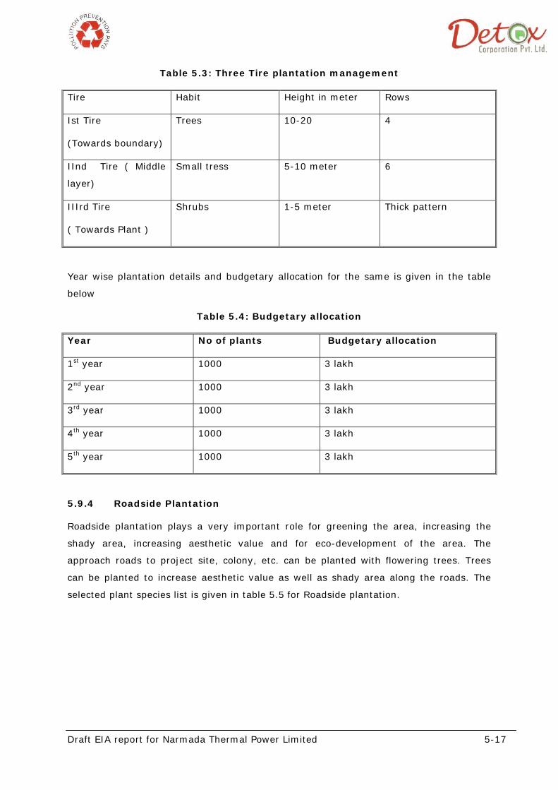
be, planted as greenbelt of 50 m width around the plant boundary. The plantation will be
in the below mentioned recommended pattern:
Draft EIA report for Narmada Thermal Power Limited 5-17
Table 5.3: Three Tire plantation management
Tire Habit Height in meter Rows
Ist Tire
(Towards boundary)
Trees 10-20 4
IInd Tire ( Middle
layer)
Small tress 5-10 meter 6
IIIrd Tire
( Towards Plant )
Shrubs 1-5 meter Thick pattern
Year wise plantation details and budgetary allocation for the same is given in the table
below
Table 5.4: Budgetary allocation
Year No of plants Budgetary allocation
1st year 1000 3 lakh
2nd year 1000 3 lakh
3rd year 1000 3 lakh
4th year 1000 3 lakh
5th year 1000 3 lakh
5.9.4 Roadside Plantation
Roadside plantation plays a very important role for greening the area, increasing the
shady area, increasing aesthetic value and for eco-development of the area. The
approach roads to project site, colony, etc. can be planted with flowering trees. Trees
can be planted to increase aesthetic value as well as shady area along the roads. The
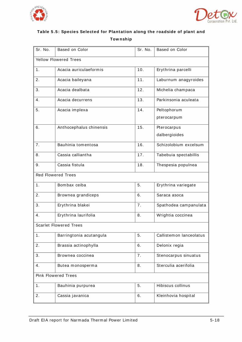
selected plant species list is given in table 5.5 for Roadside plantation.
Draft EIA report for Narmada Thermal Power Limited 5-18
Table 5.5: Species Selected for Plantation along the roadside of plant and
Township
Sr. No. Based on Color Sr. No. Based on Color
Yellow Flowered Trees
1. Acacia auriculaeformis 10. Erythrina parcelli
2. Acacia baileyana 11. Laburnum anagyroides
3. Acacia dealbata 12. Michelia champaca
4. Acacia decurrens 13. Parkinsonia aculeata
5. Acacia implexa 14. Peltophorum
pterocarpum
6. Anthocephalus chinensis 15. Pterocarpus
dalbergioides
7. Bauhinia tomentosa 16. Schizolobium excelsum
8. Cassia calliantha 17. Tabebuia spectabillis
9. Cassia fistula 18. Thespesia populnea
Red Flowered Trees
1. Bombax ceiba 5. Erythrina variegate
2. Brownea grandiceps 6. Saraca asoca
3. Erythrina blakei 7. Spathodea campanulata
4. Erythrina laurifolia 8. Wrightia coccinea
Scarlet Flowered Trees
1. Barringtonia acutangula 5. Callistemon lanceolatus
2. Brassia actinophylla 6. Delonix regia
3. Brownea coccinea 7. Stenocarpus sinuatus
4. Butea monosperma 8. Sterculia acerifolia
Pink Flowered Trees
1. Bauhinia purpurea 5. Hibiscus collinus
2. Cassia javanica 6. Kleinhovia hospital
Draft EIA report for Narmada Thermal Power Limited 5-19
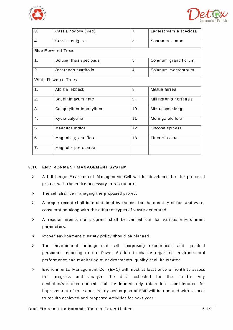
3. Cassia nodosa (Red) 7. Lagerstroemia speciosa
4. Cassia renigera 8. Samanea saman
Blue Flowered Trees
1. Bolusanthus speciosus 3. Solanum grandiflorum
2. Jacaranda acutifolia 4. Solanum macranthum
White Flowered Trees
1. Albizia lebbeck 8. Mesua ferrea
2. Bauhinia acuminate 9. Millingtonia hortensis
3. Calophyllum inophyllum 10. Mimusops elengi
4. Kydia calycina 11. Moringa oleifera
5. Madhuca indica 12. Oncoba spinosa
6. Magnolia grandiflora 13. Plumeria alba
7. Magnolia pterocarpa
5.10 ENVIRONMENT MANAGEMENT SYSTEM
A full fledge Environment Management Cell will be developed for the proposed
project with the entire necessary infrastructure.
The cell shall be managing the proposed project
A proper record shall be maintained by the cell for the quantity of fuel and water
consumption along with the different types of waste generated.
A regular monitoring program shall be carried out for various environment
parameters.
Proper environment & safety policy should be planned.
The environment management cell comprising experienced and qualified
personnel reporting to the Power Station In-charge regarding environmental
performance and monitoring of environmental quality shall be created
Environmental Management Cell (EMC) will meet at least once a month to assess
the progress and analyze the data collected for the month. Any
deviation/variation noticed shall be immediately taken into consideration for
improvement of the same. Yearly action plan of EMP will be updated with respect
to results achieved and proposed activities for next year.
Draft EIA report for Narmada Thermal Power Limited 5-20
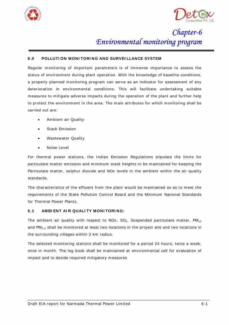
During operational phase of the proposed power plant, overall implementation of EMP
lies with the project proponent for compliance. In order to have effective implementation
of EMP, the following structure of Environment Management Cell is followed.
Figure 5.1: Environment Management Cell
The major duties and responsibilities of Environmental Management Cell shall be as
given below:
To implement the environmental management plan
To assure regulatory compliance with all relevant rules and regulations
To ensure regular operation and maintenance of pollution control devices.
To minimize environmental impacts of operations as by strict adherence to the
EMP
To initiate the environmental monitoring as per approved schedule
Review and interpretation of monitoring as per approved schedule and corrective
measures in case monitoring results are above the specified limits
Maintain documents of good environmental practices and applicable
environmental laws as ready reference
Environmental Management Cell
Environment Head
Environmental Officer
Environmental Engineer
CSR Team
Laboratory Staff
Field Staff
Draft EIA report for Narmada Thermal Power Limited 5-21
Maintain environmental related records
Coordination with regulatory agencies, external consultants, monitoring
laboratories
Maintain of log of public complain and the action taken
Allocation of Resources, Responsibility and Authority will results in successful
implementation of EMP during construction and operational phase.
5.11 BUDGETARY ALLOCATION FOR ENVIRONMENT MANAGEMENT PLAN
Table 5.6 depicts the resources required during construction and operation stages and
the estimated budget against each resource for environment management.
Table 5.6: Estimated Cost for Environmental Management Plan
S. No. Resources Budget allocated for
project
Total recurring cost every
year on maintenance
1 Green Belt 10 lakhs 1 lakh
2 Air & Noise Pollution Control 30 Crores 5 lakhs
3 Water Treatment 1.5 crore 90 lakhs
4 Process & Fire Safety Measures 1 crore 3 lakhs
5
Environmental Monitoring and
Management Programs
25 lakhs 3 lakhs
6
Road, Drainage & Rainwater
harvesting
6.5 crore 5 lakhs
Draft EIA report for Narmada Thermal Power Limited 6-1
Chapter-6 Environmental monitoring program
6.0 POLLUTION MONITORING AND SURVEILLANCE SYSTEM
Regular monitoring of important parameters is of immense importance to assess the
status of environment during plant operation. With the knowledge of baseline conditions,
a properly planned monitoring program can serve as an indicator for assessment of any
deterioration in environmental conditions. This will facilitate undertaking suitable
measures to mitigate adverse impacts during the operation of the plant and further help
to protect the environment in the area. The main attributes for which monitoring shall be
carried out are:
• Ambient air Quality
• Stack Emission
• Wastewater Quality
• Noise Level
For thermal power stations, the Indian Emission Regulations stipulate the limits for
particulate matter emission and minimum stack heights to be maintained for keeping the
Particulate matter, sulphur dioxide and NOx levels in the ambient within the air quality
standards.
The characteristics of the effluent from the plant would be maintained so as to meet the
requirements of the State Pollution Control Board and the Minimum National Standards
for Thermal Power Plants.
6.1 AMBIENT AIR QUALITY MONITORING:
The ambient air quality with respect to NOx, SO2, Suspended particulate matter, PM10
and PM2.5 shall be monitored at least two locations in the project site and two locations in
the surrounding villages within 3 km radius.
The selected monitoring stations shall be monitored for a period 24 hours, twice a week,
once in month. The log book shall be maintained at environmental cell for evaluation of
impact and to decide required mitigatory measures
Draft EIA report for Narmada Thermal Power Limited 6-2
6.2 STACK MONITORING:
All the stacks in the proposed thermal power plant shall be monitored continuously
through online system, with respect to temperature, oxides of nitrogen (NOx),
Suspended Particulate Matter (SPM), Sulphur dioxide (SOx), Carbon monoxide (CO)
level. Pulse-fluorescence method shall be used for NOx detection with data recorders in a
central control room
6.3 NOISE ENVIRONMENT
Monitoring of the noise levels is essential to assess the effectiveness of Environmental
Management Plan implemented to reduce noise levels. A good quality sound level meter
and noise exposure meter may be procured for the same. Audiometric tests shall be
conducted periodically for the employees working close to the high noise sources. The
noise levels due to machines/equipments viz. compressors, diesel generator, steam
turbine generation and boilers etc. should be monitored regularly.
6.4 WATER AND WASTE WATER QUALITY MONITORING
Daily analysis of influent and effluent streams is recommended. Sampling and analysis of
the raw water from the canal, recycled stream from DM plant and wastewater from
individual units; Cooling tower blow down, Boiler blow down, Drainage from the plant,
shall be conducted once in day. Composite sample from the collection pit shall be
collected by flow weighted hourly sampling method for characterizing the wastewater
prior to DM treatment.
6.4.1 Environment laboratory
Methods prescribed in "Standard Methods for Examination of Water and Wastewater"
prepared and published jointly by American Public Health Association (APHA), American
Water Works Association (AWWA) and Water Pollution Control Federation (WPCF), Book
on Water and Wastewater Analysis published by NEERI, Nagpur are recommended for
collection and analysis of water and wastewater samples.
An independent laboratory with facilities for chemical analysis shall be set up within the
premises. The laboratory should have a provision for fume-hood and cold room. A
separate air conditioned dust-proof room will have to be provided for installing analytical
instruments. Following instruments shall be procured for regular monitoring of various
environmental parameters.
Draft EIA report for Narmada Thermal Power Limited 6-3
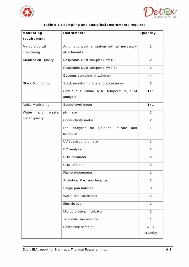
Table 6.1 : Sampling and analytical Instruments required
Monitoring
requirement
Instruments Quantity
Meteorological
monitoring
Automatic weather station with all necessary
attachments
1
Ambient air Quality Respirable Dust sampler ( PM10) 2
Respirable Dust sampler ( PM2.5) 2
Gaseous sampling attachment 4
Stack Monitoring Stack monitoring Kits and accessories 2
Continuous online NOx, temperature, SPM
analyzer
1+1
Noise Monitoring Sound level meter 1+1
Water and waster
water quality
pH meter 2
Conductivity meter 2
Ion analyzer for Chloride, nitrate and
sulphate
1
UV spectrophotometer 1
DO analyzer 2
BOD incubator 2
COD refluxer 2
Flame photometer 1
Analytical Precision balance 2
Single pan balance 3
Water distillation unit 2
Electric oven 2
Microbiological incubator 2
Trinocular microscope 1
Composite sampler 4+ 1
standby
Draft EIA report for Narmada Thermal Power Limited 6-4
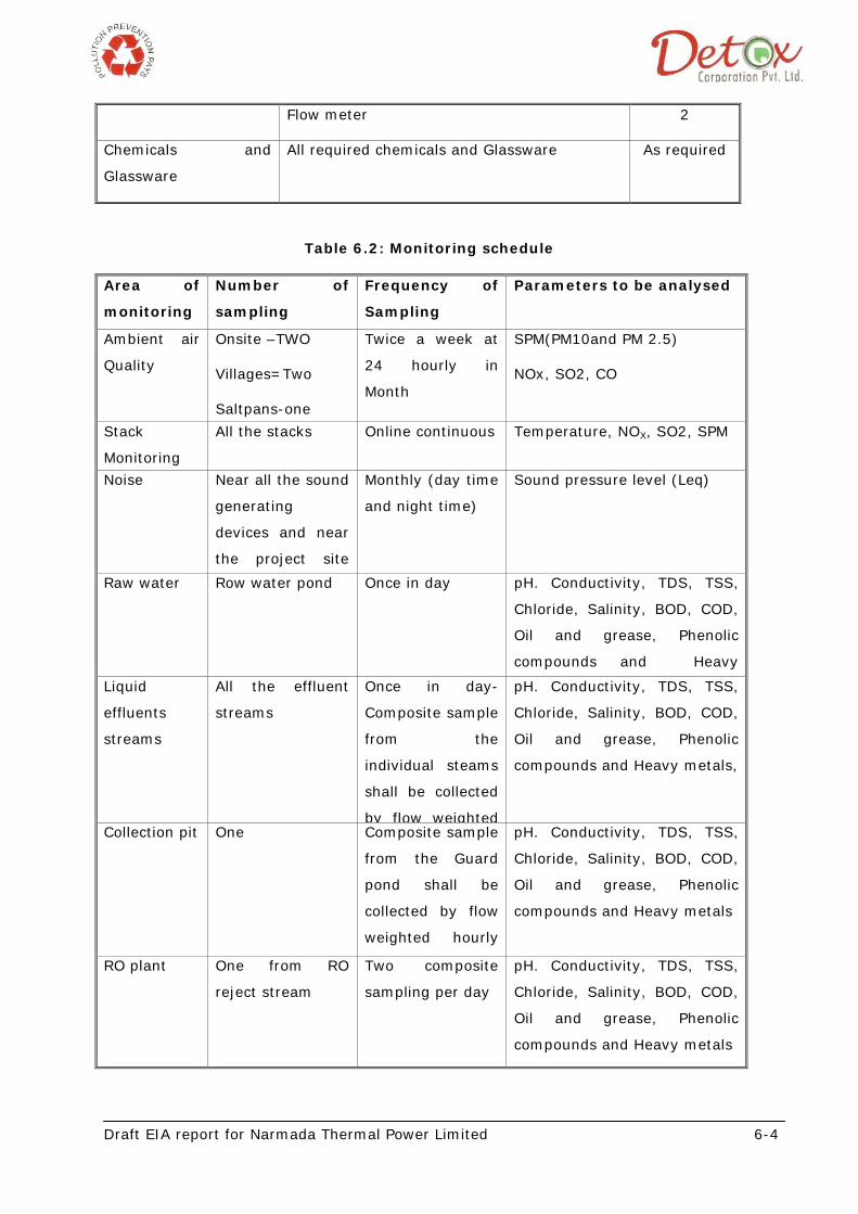
Flow meter 2
Chemicals and
Glassware
All required chemicals and Glassware As required
Table 6.2: Monitoring schedule
Area of
monitoring
Number of
sampling
Frequency of
Sampling
Parameters to be analysed
Ambient air
Quality
Onsite –TWO
Villages=Two
Saltpans-one
Twice a week at
24 hourly in
Month
SPM(PM10and PM 2.5)
NOx, SO2, CO
Stack
Monitoring
All the stacks Online continuous Temperature, NOX, SO2, SPM
Noise Near all the sound
generating
devices and near
the project site
Monthly (day time
and night time)
Sound pressure level (Leq)
Raw water Row water pond Once in day pH. Conductivity, TDS, TSS,
Chloride, Salinity, BOD, COD,
Oil and grease, Phenolic
compounds and Heavy
Liquid
effluents
streams
All the effluent
streams
Once in day-
Composite sample
from the
individual steams
shall be collected
by flow weighted
pH. Conductivity, TDS, TSS,
Chloride, Salinity, BOD, COD,
Oil and grease, Phenolic
compounds and Heavy metals,
Collection pit One Composite sample
from the Guard
pond shall be
collected by flow
weighted hourly
pH. Conductivity, TDS, TSS,
Chloride, Salinity, BOD, COD,
Oil and grease, Phenolic
compounds and Heavy metals
RO plant One from RO
reject stream
Two composite
sampling per day
pH. Conductivity, TDS, TSS,
Chloride, Salinity, BOD, COD,
Oil and grease, Phenolic
compounds and Heavy metals
Draft EIA report for Narmada Thermal Power Limited 6-5
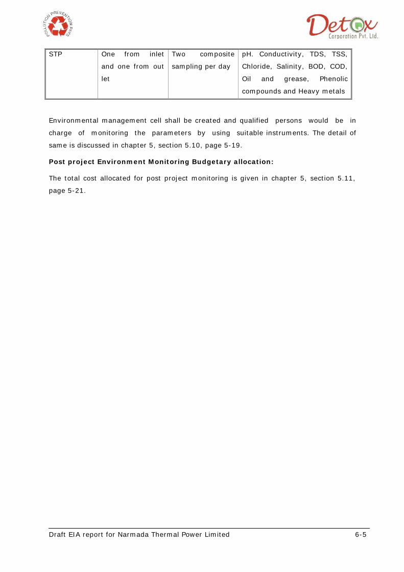
STP One from inlet
and one from out
let
Two composite
sampling per day
pH. Conductivity, TDS, TSS,
Chloride, Salinity, BOD, COD,
Oil and grease, Phenolic
compounds and Heavy metals
Environmental management cell shall be created and qualified persons would be in
charge of monitoring the parameters by using suitable instruments. The detail of
same is discussed in chapter 5, section 5.10, page 5-19.
Post project Environment Monitoring Budgetary allocation:
The total cost allocated for post project monitoring is given in chapter 5, section 5.11,
page 5-21.
Draft EIA report of Narmada Thermal Power Limited 7-1
Chapter-7 Project Benefits
The company is committed for contribution of funds and provides the services for the
upliftment of local community in the nearby villages. The different activities to be
undertaken by the company are mentioned in this chapter
7.1 Socio economic activities
Programs for environmental education and public participation shall be developed
with the help of audio visual aids to create awareness about the activities.
Camps to apprise people of likely environmental hazards due to proposed
facilities shall be organized.
Proper awareness campaign shall be organized by the project proponent for water
conservation.
Periodic health check up camps shall be organized by the project authority for
workers families.
Free Medical Facility inside the premises for all employees & tie up with the
nearest hospital for further treatment
Medical center will provided to the near by villager at the Free cost.
In order to increase the aesthetic environment, road side plantation program shall
be carried out in the near by villages.
The company shall make collaborative effort with the local authorities of the
village for the social welfare activities to be undertaken in the villages.
Improvement in infrastructure facilities shall be done in collaboration with the
local gram Panchayat.
Widening of internal road from the project site to the major district road shall be
under taken by the project proponent.
Street lights in the villages shall be provided
Group Insurance to all employees over and above the Employees State Insurance
Scheme
Subsidized food in a well equipped and hygienic canteen
Subsidized Transportation facility for all employees for all shifts
Annual get-together and rewards for workers’ kids who have shown brilliance in
education, sports, cultural activities
Free distribution of PPE and 2 sets of Uniform per year
Draft EIA report of Narmada Thermal Power Limited 7-2
Fire & Safety Training will be imparted to employees.
Fire fighting and Safety Week will be observed and quiz and essay competitions
will be organized to develop awareness in employees on the subject.
Celebration of International Environment Day every year on 5th June will be
marked by plantation of number of trees by employees in order to develop
awareness in them about protecting environment from pollution and to save
earth.
Community Awareness programmed like Aids awareness, Polio camps, Eye camps
and blood donation camps will be organized in the company and in its vicinity
from time to time for the benefit of employees and their families and people living
in the surrounding area.
Regular donations will be made in the nearby schools and temples.
7.2 EMPLOYMENT POTENTIAL:
There will be increase in the employment facilities due to the upcoming project. The total
no. of skilled and unskilled worker to be employed for the proposed project is as given
below.
Table 7.1: Employment details
No. of skilled employees 70 nos.
No. of unskilled employees 100 nos.
Total employees for proposed project 170 nos.
7.3 BUDGETARY ALLOCATION
Adequate funds as per the statutory requirement will be allotted for various socio
economic activities to be undertaken in the villages. The details regarding fund allocation
for next five years for the socio economic upliftment of the area is as given in the table
below:
Year Budgetary allocation
2012 20 lakh
2013 20 lakh
2014 20 lakh
2015 20 lakh
2016 20 lakh
Draft EIA report for Narmada Thermal Power Limited 8-1
Chapter 8 Risk assessment and damage control
8.1 INTRODUCTION
A risk assessment is a careful examination of consequences resulting from the undesired
events that could cause harm to people or property, so that sufficient precautions can be
taken. Workers and others have a right to be protected from harm caused by a failure to
take reasonable control measures.
8.2 OBJECTIVES OF THE RISK ASSESSMENT
As per the requirements stated in the Terms of Reference of the EIA study, the risk
assessment study has been undertaken to address the following aspects:
• To identify and assess those fire and explosion hazard arising from the storage
and use of the fuel in the project that require management in order to comply
with regulatory requirements, company policy and business requirements.
• To eliminate or reduce to as low as reasonably practical in terms of risk to human
health, risk of injury, risk of damage to plant, equipment and environment,
business interruption or loss etc.
8.3 THE RISK ASSESSMENT PROCESS
Risk assessment involves the identification of the hazards present and an estimate of the
extent of the risks involved, taking into account whatever precautions are inherent to the
process/activity.
There are more than one approach to risk assessment, for example:
• Look at each activity (not forgetting non-routine activities, e.g., maintenance,
breakdowns etc.). That could cause harm or adverse effects;
• Look at hazards and risks in groups e.g. machinery, transport, materials,
electrical etc;
• Look at each section e.g. stores, workshop, laboratory, office, etc.
The approach should match the circumstances.
The actions required for an assessment to be suitable and sufficient and compliant with
other legal requirements are summarized in the following five steps:
Step 1 - Identify the hazards
Step 2 - Decide who might be harmed and how
Step 3 - Evaluate the risks and decide on precautions
Draft EIA report for Narmada Thermal Power Limited 8-2
Step 4 - Record your findings and implement them
Step 5 - Review your assessment and update if necessary
Step 1 Identify the hazards
There are a number of simple ways in which hazards can be identified. In order to
achieve a suitable and sufficient risk assessment it is essential to identify all the hazards
associated with an activity.
Step 2 Decide who might be harmed
Look for who may be harmed by the hazards and how. Include people who may not be
in the workplace all the time, e.g. cleaners, visitors, contractors, maintenance personnel,
members of the public, etc. If the workplace is shared with others, include them too if
there is a chance that they may be harmed in some way by the activities
Step 3 Evaluate the risks arising from the hazards and decide what should be
done to control them
Is there any real chance of harm? Take account of any precautions that are inherent to
the process/activity; check against guidelines and consider whether the precautions are
adequate and, if not, what further action is needed.
Go through the following questions:
• can the hazard be removed altogether (substitution of the hazard or permanent
removal of the hazard)
• If not, how can the risks be controlled so that harm is unlikely (control measures
taken in order to minimize/remove the risk).
Hierarchies of Control: There are five classes of measure for controlling risk and they
need to be considered and applied in the order below:
1. Elimination/substitution
• Elimination (e.g. buying ready-mixed or pre-assembled materials or
equipment);
• Substitution by something less hazardous and involving less risk.
2. Engineering controls
• Enclosure (enclose it in a way that eliminates or controls the hazard/risk);
• Guarding/segregation of people.
3. Administrative controls
Draft EIA report for Narmada Thermal Power Limited 8-3
• Safe system of work that reduces the risk to an acceptable level (e.g.
standard operating procedure);
• Permits to work;
• Controlled areas;
• Written procedures that are known and understood by those affected;
• Adequate supervision;
• Identification of training needs.
4. Personal protective equipment
5. Information/instruction (e.g., signs, handouts)
Some controls are essential. In many cases a suitable combination of control methods
may be necessary.
Step 4 Record the findings and put into practice the control measures.
The record can be greatly simplified by referring to other documentation, such as
manuals, health and safety procedures. These may well already have listed hazards for
equipment or processes and the precautions and arrangements for controlling risk. It is
not necessary to repeat all that. Similarly, reference can be made to other assessments
where they are relevant. If the required other assessment does not exist then the
outcome of this general risk assessment will be to request the appropriate specific
assessment.
If a workplace is shared, others must be told about any risks the work could cause them,
and what is being done to protect them.
Step 5 Review the assessment from time to time and revise it if necessary
Workplace changes, new equipment, substances and procedures could lead to new
hazards and risks. If there is any significant change, then the assessment should be
revised to take account of the new hazard. In any case, it is good practice for
assessments to be reviewed periodically and in some cases, it is a statutory requirement.
However, don't amend assessments for every trivial change, or for every new job that
has to be attempted. Walk around the area and look afresh at what can reasonably be
foreseen as likely to cause harm. Ask the people who work there what they think.
They may come up with hazards which they have noticed in the course of their work and
which are not immediately obvious. Accident records, manufacturers' instructions, or
data sheets can also help.
Draft EIA report for Narmada Thermal Power Limited 8-4
8.4 IDENTIFICATION OF HAZARDS
8.4.1 Fire And Explosion Index & Toxicity Index
Fire and Explosion Index (F&EI) is an important technique employed for hazards
identification process. Consequence analysis then quantifies the vulnerable zone for a
conceived incident. Once vulnerable zone is identified for an incident, measures can be
formulated to eliminate or reduce damage to plant and potential injury to personnel.
Rapid ranking of hazard of an entire installation, if it is small, or a portion of it, if it is
large, is often done to obtain a quick assessment of degree of the risk involved. The Dow
Fire and Explosion Index (F&EI) and Toxicity Index (TI) are the most popular methods
for Rapid Hazard Ranking. These are based on a formal systematized approach, mostly
independent of judgmental factors, for determining the relative magnitude of the
hazards in an installation using hazardous (inflammable, explosive and toxic) materials.
The steps involved in the determination of the F&EI and TI are:
· Selection of a pertinent process unit
· Determination of the Material Factor (MF)
· Determination of the Toxicity Factor (Th)
· Determination of the Supplement to Maximum Allowable Concentration(Ts)
· Determination of the General Process Hazard Factor (GPH)
· Determination of the Special Process Hazard Factor (SPH)
· Determination of the F&EI value
· Determination of the TI value
· Determination of the Exposure Area
8.4.1.1 Hazardous Material Identification Methodology
From the preliminary appraisal of Material Safety Data Sheet, it is observed that both
furnace oil and natural gas are inflammable and hazardous. F&EI and TI values have
been computed for Natural gas supply pipeline and Furnace oil storage (500 KL) has
been conducted.
In general, the higher is the value of material factor (MF), the more inflammable and
explosive is the material. Similarly, higher values of toxicity factor (Th) and supplement
to maximum allowable concentration (Ts) indicate higher toxicity of the material. The
tabulated values of MF, Th and Ts are given in Dows Fire and Explosion Index Hazard
Classification Guide. For compounds not listed in Dow reference, MF can be computed
from the knowledge of flammability and reactivity classification, Th can be computed
Draft EIA report for Narmada Thermal Power Limited 8-5
from the knowledge of the National Fire Protection Association (NFPA) Index and Ts can
be obtained from the knowledge of maximum allowable concentration (MAC) values. The
MF, Th and Ts values are respectively 16, 0 and 50 for crude oil, 21, 0 and 50 for natural
gas, and 10, 0 and 50 for HSD.
General process hazards (GPH) are computed by adding the penalties applied for the
various process factor.
Special process hazards (SPH) are computed by adding the penalties applied for the
process and natural factors.
Both General process hazards and Special process hazards corresponding to various
process and natural factors are used with MF to compute F&EI value and with Th and Ts
to compute TI value.
8.4.1.2 F&EI Computation
F&EI value computed for TPS and CTT from GPH and SPH values using the following
formula are given in Table 6.1:
F&EI = MF x [1 + GPH (total)] x [1 + SPH (total)]
8.4.1.3 Toxicity Index (TI)
Toxicity index (TI) is computed from toxicity factor (Th) and supplement to maximum
allowable concentrations (Ts) using the following relationship:
TI = (Th + Ts) x [1 + GPH (total) + SPH (total)]/100
Calculation for F&EI as well as TI is given in table shown below for coal, HSD and
chlorine.
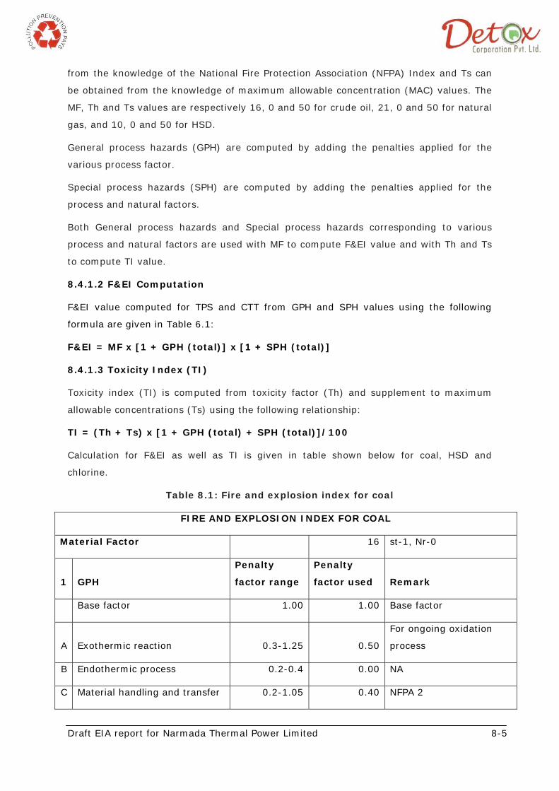
Table 8.1: Fire and explosion index for coal
FIRE AND EXPLOSION INDEX FOR COAL
Material Factor 16 st-1, Nr-0
1 GPH
Penalty
factor range
Penalty
factor used Remark
Base factor 1.00 1.00 Base factor
A Exothermic reaction 0.3-1.25 0.50
For ongoing oxidation
process
B Endothermic process 0.2-0.4 0.00 NA
C Material handling and transfer 0.2-1.05 0.40 NFPA 2
Draft EIA report for Narmada Thermal Power Limited 8-6
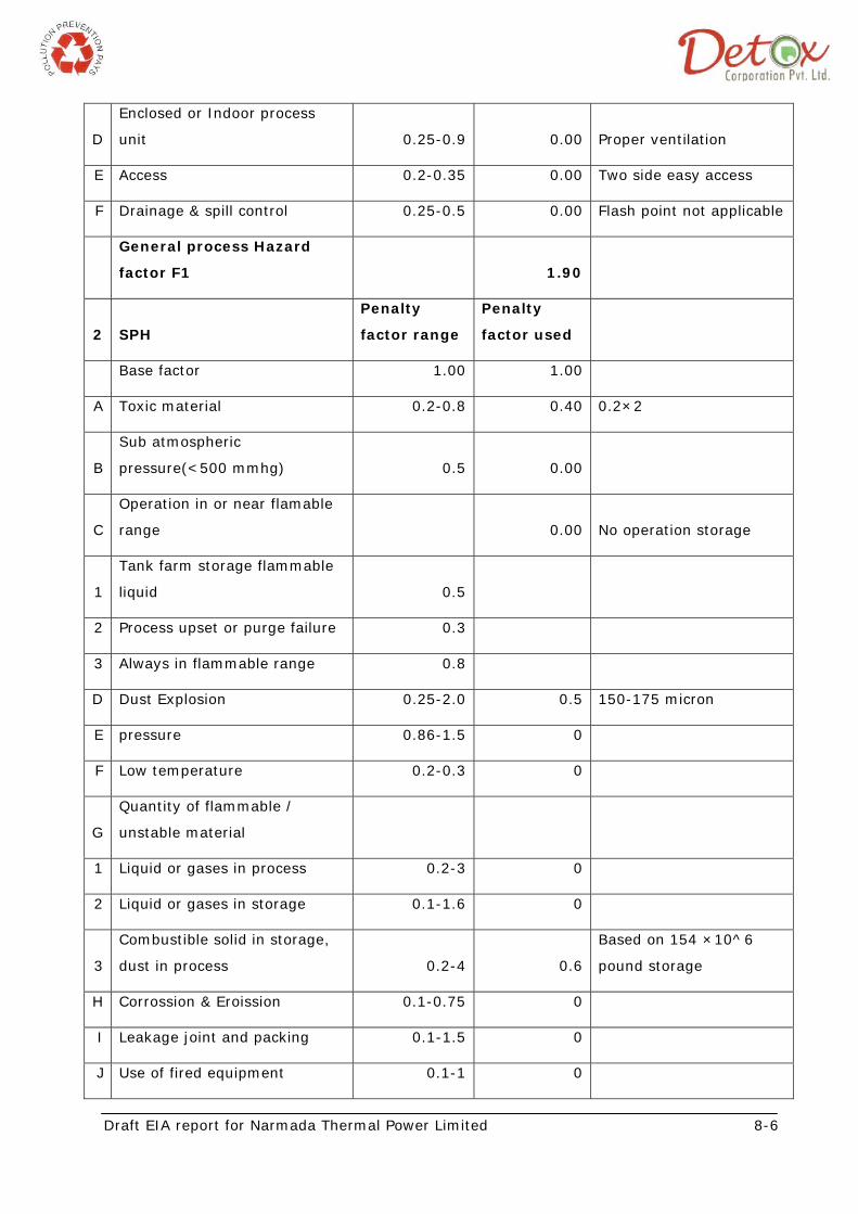
D
Enclosed or Indoor process
unit 0.25-0.9 0.00 Proper ventilation
E Access 0.2-0.35 0.00 Two side easy access
F Drainage & spill control 0.25-0.5 0.00 Flash point not applicable
General process Hazard
factor F1 1.90
2 SPH
Penalty
factor range
Penalty
factor used
Base factor 1.00 1.00
A Toxic material 0.2-0.8 0.40 0.2×2
B
Sub atmospheric
pressure(<500 mmhg) 0.5 0.00
C
Operation in or near flamable
range 0.00 No operation storage
1
Tank farm storage flammable
liquid 0.5
2 Process upset or purge failure 0.3
3 Always in flammable range 0.8
D Dust Explosion 0.25-2.0 0.5 150-175 micron
E pressure 0.86-1.5 0
F Low temperature 0.2-0.3 0
G
Quantity of flammable /
unstable material
1 Liquid or gases in process 0.2-3 0
2 Liquid or gases in storage 0.1-1.6 0
3
Combustible solid in storage,
dust in process 0.2-4 0.6
Based on 154 ×10^6
pound storage
H Corrossion & Eroission 0.1-0.75 0
I Leakage joint and packing 0.1-1.5 0
J Use of fired equipment 0.1-1 0
Draft EIA report for Narmada Thermal Power Limited 8-7
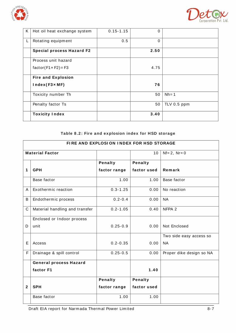
K Hot oil heat exchange system 0.15-1.15 0
L Rotating equipment 0.5 0
Special process Hazard F2 2.50
Process unit hazard
factor(F1×F2)=F3 4.75
Fire and Explosion
Index(F3×MF) 76
Toxicity number Th 50 Nh=1
Penalty factor Ts 50 TLV 0.5 ppm
Toxicity Index 3.40
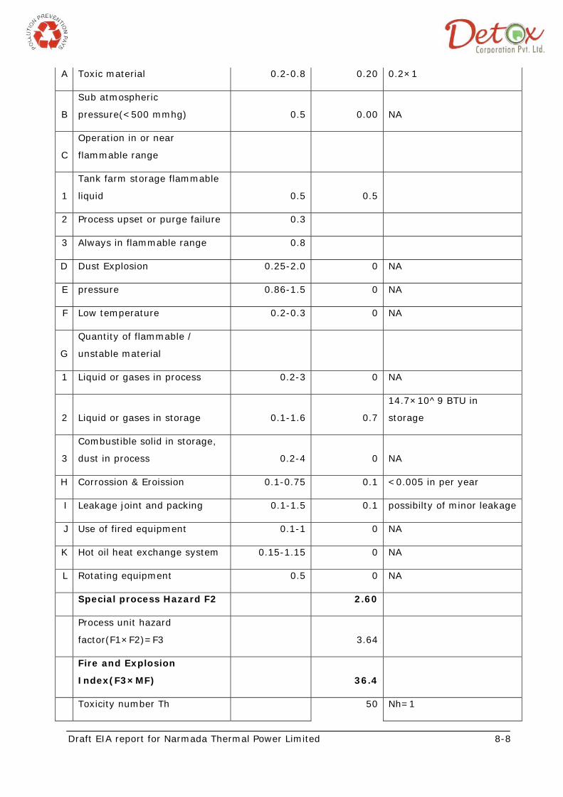
Table 8.2: Fire and explosion index for HSD storage
FIRE AND EXPLOSION INDEX FOR HSD STORAGE
Material Factor 10 Nf=2, Nr=0
1 GPH
Penalty
factor range
Penalty
factor used Remark
Base factor 1.00 1.00 Base factor
A Exothermic reaction 0.3-1.25 0.00 No reaction
B Endothermic process 0.2-0.4 0.00 NA
C Material handling and transfer 0.2-1.05 0.40 NFPA 2
D
Enclosed or Indoor process
unit 0.25-0.9 0.00 Not Enclosed
E Access 0.2-0.35 0.00
Two side easy access so
NA
F Drainage & spill control 0.25-0.5 0.00 Proper dike design so NA
General process Hazard
factor F1 1.40
2 SPH
Penalty
factor range
Penalty
factor used
Base factor 1.00 1.00
Draft EIA report for Narmada Thermal Power Limited 8-8
A Toxic material 0.2-0.8 0.20 0.2×1
B
Sub atmospheric
pressure(<500 mmhg) 0.5 0.00 NA
C
Operation in or near
flammable range
1
Tank farm storage flammable
liquid 0.5 0.5
2 Process upset or purge failure 0.3
3 Always in flammable range 0.8
D Dust Explosion 0.25-2.0 0 NA
E pressure 0.86-1.5 0 NA
F Low temperature 0.2-0.3 0 NA
G
Quantity of flammable /
unstable material
1 Liquid or gases in process 0.2-3 0 NA
2 Liquid or gases in storage 0.1-1.6 0.7
14.7×10^9 BTU in
storage
3
Combustible solid in storage,
dust in process 0.2-4 0 NA
H Corrossion & Eroission 0.1-0.75 0.1 <0.005 in per year
I Leakage joint and packing 0.1-1.5 0.1 possibilty of minor leakage
J Use of fired equipment 0.1-1 0 NA
K Hot oil heat exchange system 0.15-1.15 0 NA
L Rotating equipment 0.5 0 NA
Special process Hazard F2 2.60
Process unit hazard
factor(F1×F2)=F3 3.64
Fire and Explosion
Index(F3×MF) 36.4
Toxicity number Th 50 Nh=1
Draft EIA report for Narmada Thermal Power Limited 8-9
Penalty factor Ts 50 TLV more than 50 ppm
Toxicity Index 3
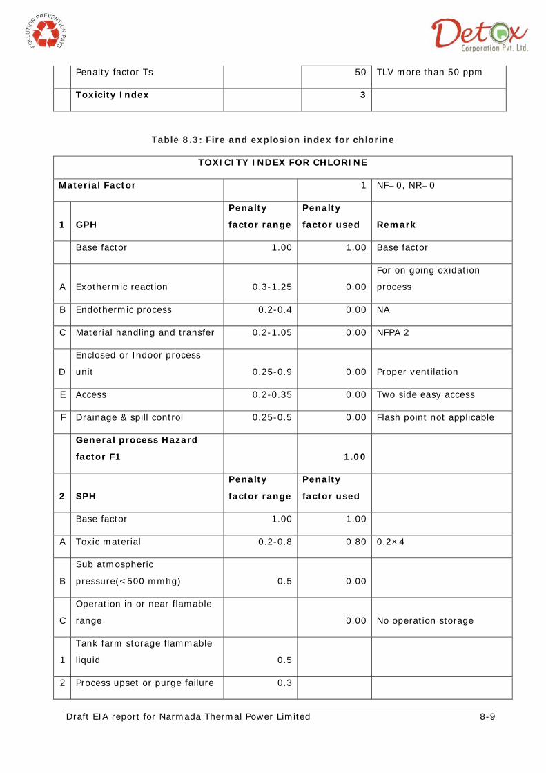
Table 8.3: Fire and explosion index for chlorine
TOXICITY INDEX FOR CHLORINE
Material Factor 1 NF=0, NR=0
1 GPH
Penalty
factor range
Penalty
factor used Remark
Base factor 1.00 1.00 Base factor
A Exothermic reaction 0.3-1.25 0.00
For on going oxidation
process
B Endothermic process 0.2-0.4 0.00 NA
C Material handling and transfer 0.2-1.05 0.00 NFPA 2
D
Enclosed or Indoor process
unit 0.25-0.9 0.00 Proper ventilation
E Access 0.2-0.35 0.00 Two side easy access
F Drainage & spill control 0.25-0.5 0.00 Flash point not applicable
General process Hazard
factor F1 1.00
2 SPH
Penalty
factor range
Penalty
factor used
Base factor 1.00 1.00
A Toxic material 0.2-0.8 0.80 0.2×4
B
Sub atmospheric
pressure(<500 mmhg) 0.5 0.00
C
Operation in or near flamable
range 0.00 No operation storage
1
Tank farm storage flammable
liquid 0.5
2 Process upset or purge failure 0.3
Draft EIA report for Narmada Thermal Power Limited 8-10
3 Always in flammable range 0.8
D Dust Explosion 0.25-2.0 0
E pressure 0.86-1.5 0.86 9 Kg storage
F Low temperature 0.2-0.3 0
G
Quantity of flammable /
unstable material
1 Liquid or gases in process 0.2-3 0
2 Liquid or gases in storage 0.1-1.6 0
3
Combustible solid in storage,
dust in process 0.2-4 0
H Corrosion & Erosion 0.1-0.75 0.1
rate less than 0.15mm per
year
I Leakage joint and packing 0.1-1.5 0 Not minor leakage
J Use of fired equipment 0.1-1 0
K Hot oil heat exchange system 0.15-1.15 0
L Rotating equipment 0.5 0
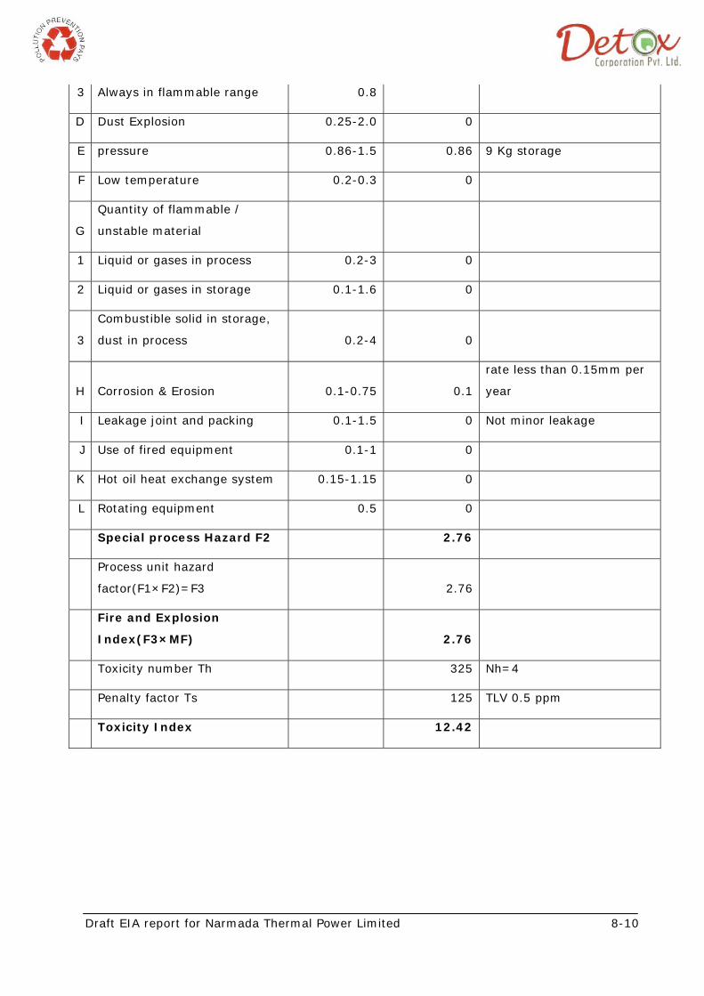
Special process Hazard F2 2.76
Process unit hazard
factor(F1×F2)=F3 2.76
Fire and Explosion
Index(F3×MF) 2.76
Toxicity number Th 325 Nh=4
Penalty factor Ts 125 TLV 0.5 ppm
Toxicity Index 12.42
Draft EIA report for Narmada Thermal Power Limited 8-11
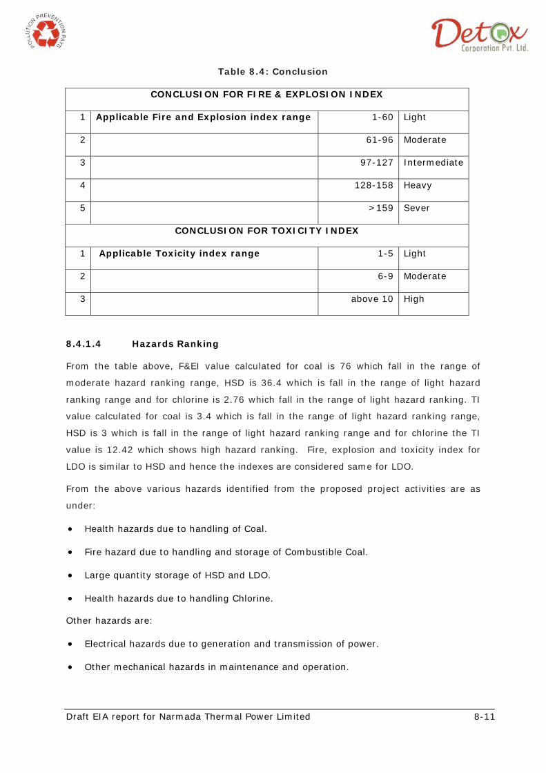
Table 8.4: Conclusion
CONCLUSION FOR FIRE & EXPLOSION INDEX
1 Applicable Fire and Explosion index range 1-60 Light
2 61-96 Moderate
3 97-127 Intermediate
4 128-158 Heavy
5 >159 Sever
CONCLUSION FOR TOXICITY INDEX
1 Applicable Toxicity index range 1-5 Light
2 6-9 Moderate
3 above 10 High
8.4.1.4 Hazards Ranking
From the table above, F&EI value calculated for coal is 76 which fall in the range of
moderate hazard ranking range, HSD is 36.4 which is fall in the range of light hazard
ranking range and for chlorine is 2.76 which fall in the range of light hazard ranking. TI
value calculated for coal is 3.4 which is fall in the range of light hazard ranking range,
HSD is 3 which is fall in the range of light hazard ranking range and for chlorine the TI
value is 12.42 which shows high hazard ranking. Fire, explosion and toxicity index for
LDO is similar to HSD and hence the indexes are considered same for LDO.
From the above various hazards identified from the proposed project activities are as
under:
• Health hazards due to handling of Coal.
• Fire hazard due to handling and storage of Combustible Coal.
• Large quantity storage of HSD and LDO.
• Health hazards due to handling Chlorine.
Other hazards are:
• Electrical hazards due to generation and transmission of power.
• Other mechanical hazards in maintenance and operation.
Draft EIA report for Narmada Thermal Power Limited 8-12
Consequences of hazards also depend on prevailing meteorological conditions and
density of population in surrounding areas.
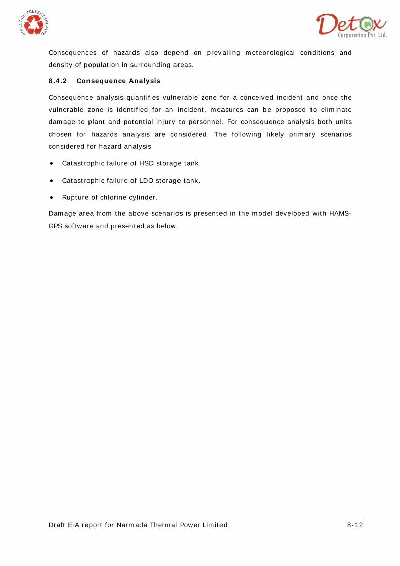
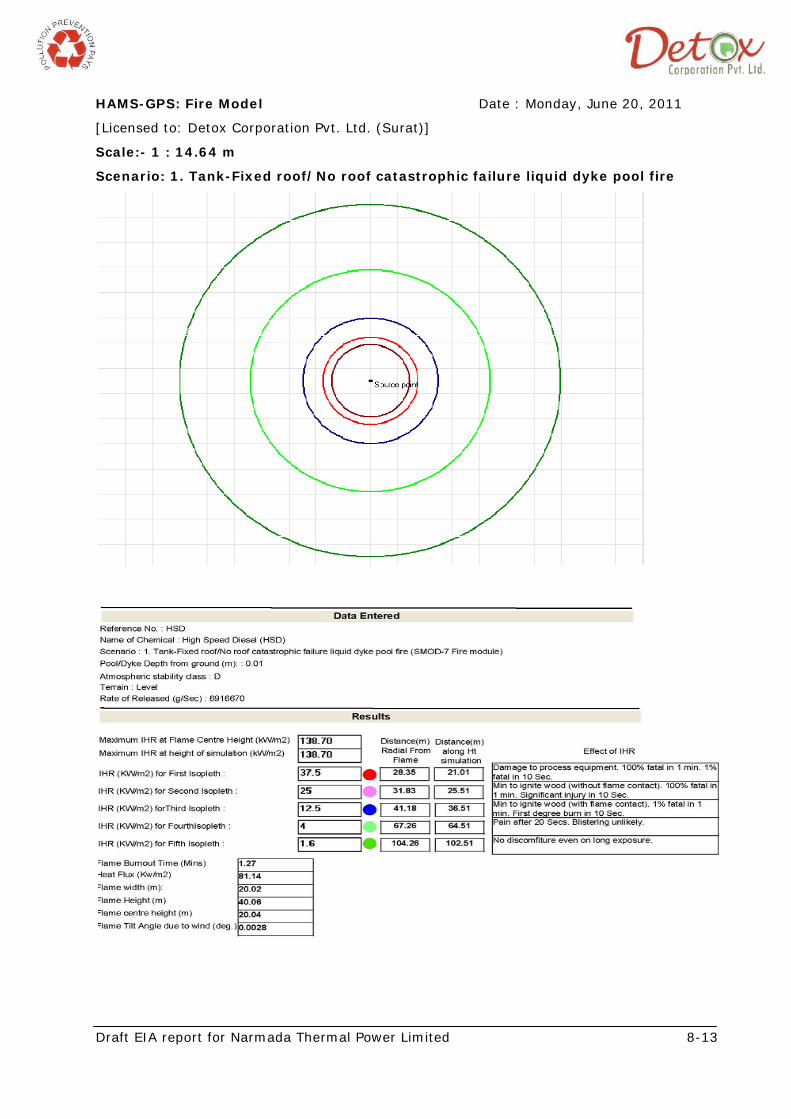
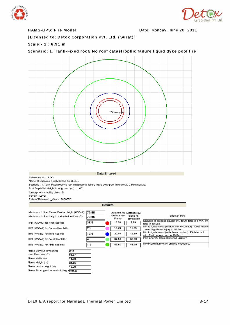
8.4.2 Consequence Analysis
Consequence analysis quantifies vulnerable zone for a conceived incident and once the
vulnerable zone is identified for an incident, measures can be proposed to eliminate
damage to plant and potential injury to personnel. For consequence analysis both units
chosen for hazards analysis are considered. The following likely primary scenarios
considered for hazard analysis
• Catastrophic failure of HSD storage tank.
• Catastrophic failure of LDO storage tank.
• Rupture of chlorine cylinder.
Damage area from the above scenarios is presented in the model developed with HAMS-
GPS software and presented as below.
Draft EIA report for Narmada Thermal Power Limited 8-13
HAMS-GPS: Fire Model Date : Monday, June 20, 2011
[Licensed to: Detox Corporation Pvt. Ltd. (Surat)]
Scale:- 1 : 14.64 m
Scenario: 1. Tank-Fixed roof/No roof catastrophic failure liquid dyke pool fire
Draft EIA report for Narmada Thermal Power Limited 8-14
HAMS-GPS: Fire Model Date: Monday, June 20, 2011
[Licensed to: Detox Corporation Pvt. Ltd. (Surat)]
Scale:- 1 : 6.91 m
Scenario: 1. Tank-Fixed roof/No roof catastrophic failure liquid dyke pool fire
Draft EIA report for Narmada Thermal Power Limited 8-15
HAMS-GPS: Dispersion Model Date: Thursday, June 16, 2011
[Licensed to: Detox Corporation Pvt. Ltd. (Surat)]
Scale:- 1 : 358.93 m
Scenario: 1. CLG Tank rupture Flash Vaporization forming Gas Cloud (SMOD-b6 Puff Dispersion DF)
Draft EIA report for Narmada Thermal Power Limited 8-16
8.5 RISK ANALYSIS DUE TO STORAGE AND HANDLING OF COAL
Area of assessment
The proposed power generation capacity of the project is 270 MW.
Coal Requirement
The annual coal requirement at 85% PFL for 270 MW is about 1.144 million tones
considering using 100% imported coal and 1.53 million tones considering using 100%
Indian coal. The coal storage will be for 30 days requirement. Thus the maximum coal
storage at site will be 95333 MT in case of 100% imported coal and 127500MT in case of
using 100% Indian coal.
Considering the fact that the Coal storage area will be provided with necessary fire
hydrant and dust suppression systems.
Ignition temperature of coal: 260 deg F to 365 deg F
Typical label and MSDS information that contains particulars like Warning and safety
phrases such as ‘highly combustible’, etc., Physical and health hazards, Guidelines on
safe use, storage and transport, Spill control and clean up, First aid should be placed in
the area.
Coal Linkage and Transport to site
It is envisaged that the proposed station will be linked with Indian coal fields of coal
Indian / Imported coal and will be transported to the port of Dahej which has all the
facilities for large volume of coal handling. Imported coal will also be received at the
port. From the port the coal will be transported by trucks to the site.
8.5.1 Hazard Identification
Hazards in Coal Handling
• Exposure to coal dust in handling coal.
• Inhalation
• Ingestion
• Skin contact
• Eye contact
• Fall of object [Coal Pieces] while collecting spilled coal below running conveyors.
Draft EIA report for Narmada Thermal Power Limited 8-17
Fire hazards in Coal Storage
• Self heating of coal to its ignition temperature, resulting in what is called
spontaneous combustion, is a phenomenon identified with coal storage in
industries. Virtually all grades of coal (except high grade anthracite) are
vulnerable to spontaneous heating and ignition. Although the precise cause of
the spontaneous combustion of coal is not well defined, it is believed that when
coal is freshly mined, the fresh surface of coal pieces liberate absorbed hydro-
carbons, chiefly methane (in varying amounts), After the escape of the absorbed
gases, the exposed surface of coal particles get oxidized by the oxygen in the
ambient air. The oxidation is very slow but heat is generated in the process. If
the heat is not allowed to dissipate, the temperature of the coal may rise
gradually but sufficiently enough to cause the mass to ignite. It is also believed
that this self heating of coal usually occurs in about 90 to 120 days after the coal
is extracted in mining operations.
• Oxidation in coal stacks takes place mainly from loosely packed coal stacks and
the consequent availability of oxygen in the voids of the stacks. The rate of
oxidation is high at the outer surface of the stacks because of the availability of
abundant oxygen there. The rise in temperature, however, cannot be detected
due to the dissipation of heat by air movement. This zone extends roughly up to
a depth of 0.5m. The situation beyond this zone, say up to a depth of 1.5m, is
different. The coal in this zone is also different. The coal in this zone also
oxidisers fairly rapidly in the presence of adequate quantity of air entering the
stack, but the heat generated in the course of this reaction is generally partially
dissipated through convection and conduction. The heat transfer from this zone
depends on factors like ambient temperature, rate of air movement around that
zone, free moisture available in the material and thermal conductivity. The
residual heat thus present in this zone further raises the temperature of the coal
mass until it attains the critical (threshold) temperature i.e. the auto ignition
temperature. Once it reaches critical temperature, the coal in the zone starts
burning and smoking and eventually erupts in flames. Proneness to spontaneous
combustion, therefore, can be determined by ascertaining the critical oxidation
temperature or crossing point. The lower the crossing point, the more is the
proneness to self heating.
• All types of coal, when exposed to the atmosphere, are liable to suffer
deterioration of quality through surface oxidation, but the extent of deterioration
differs from type to type. Lignite is a type of brown coal containing a high
percentage of volatiles. It is subject to weathering much more rapidly than
Draft EIA report for Narmada Thermal Power Limited 8-18
bituminous coal. It contains a large percentage of moisture (as much as 40%) as
mined, of which nearly 20% exists even before it is mined. Under dry hot
ambient conditions, particularly in India where temperature in a shed could go up
to 450C and humidity to less than 30%, lignite oxidation rate could be high. The
rate of release of carbon monoxide which is indicative of the oxidation rate may
be as high as 70 m3 of CO per ton of lignite, which is about 100 times that of
normal bituminous coal. It has also been observed that in large coal storage
yards left undisturbed for long periods, smoldering takes place at the surface
layers of the pile. In case of lignite, this phenomenon is more rapid. Highly
volatile coal is particularly liable to spontaneous combustion.
Coal is highly combustible and the range of ignition temperature range for coal is 260-
365 degF.
Explosion hazard during coal storage:
Dust Explosion, an explosion caused by the sudden igniting of a mixture of air and a
heavy concentration of combustible dust particles. A mixture containing fine dust is more
explosive because there is more exposed particle surface.
The flame or spark that sets off a dust explosion can be produced by friction, static
electricity, matches, defective wiring, blowtorches, or any open flame. Dust composed of
grain, flour, starch, coffee, cotton, coal, sugar, or other organic materials is highly
explosive.
8.5.2 Risk Evaluation and Control Measures
Control measures to be adopted during storage of coal
Storage of large quantities of coal requires two conditions to be met viz. (i) avoidance of
deterioration in quality and (ii) avoidance of heating in the pile. While neither of the
conditions can be fulfilled completely, deterioration and risk of fire can be reduced to a
minimum by careful manipulation of the conditions of storage.
As basic necessary steps to avoid spontaneous heating in coal storage, the following
guidelines will be adopted:
• The ground or floor where coal is to be stored will be thoroughly cleaned of
leaves, grass, weds, pieces of wood, cotton waste or other organic waste and
precautions taken to prevent such matter from getting under, into or on the coal
pile.
• There will not be any steam or hot process pipelines or openings or sewers under,
into, through or adjacent to coal piles.
Draft EIA report for Narmada Thermal Power Limited 8-19
• The storage site will be provided with drainage facility to prevent accumulation of
water on the ground.
• Special attention will be given to monitoring of the coal stack, in excess of 420C.
• The pile will be planned so as to facilitate dissipation of heat by wind from the
surface of the pile. Any barrier / obstruction to wind will be removed.
• Newly broken fines of coal are more susceptible to spontaneous heating.
Dropping coal from heights while piling will be avoided.
• Conical piles will be avoided - these storage will be built up in layers by roll
packing - this helps to exclude oxygen and thus prevents fires by discouraging
spontaneous heating.
• As far as possible coal piles from different sources will not be stored together.
• Coal stock should be limited in height. Low-grade coal will not be piled higher
than 3 meters and best grade not higher than 4-5 meters. Coal will be stored in
mixed sizes as too many fines will be hazardous.
• No standing timber or pipes, poles, etc. will be allowed in the piles. These may
give rise to formation of duct which allows sluggish air flow which may be
sufficient for heating the coal but not sufficient to dissipate the heat.
It is recommended to locate coal yards at least 6-7 meters away from any important
buildings and other combustible storage areas.
Control measures to be adopted for prevention of Coal Stock Fires
During the period of low off take, coal stock generally tends to build up to alarming
levels. Since most of the grades of coal are susceptible to spontaneous ignition if it is
undisturbed for a certain period of time, risk of fire exists in coal stacks. Following
precautions will be taken for preventing spread of coal stock fire:
• Consumption of coal will be done on first in-first out basis.(FIFO)
• Temperature of the coal pile will be checked regularly. Specific attention will be
given to the sloped sides of the piles where vulnerable air pockets exist. If pile
temperature exceeds 700C, the pile will be opened and placed the overheated
material in a separate small pile or use it promptly.
• Inspection of stack will be done to detect smoldering and organize removal /
consumption of the smoldering coal on priority and to extinguish the flames in
time. Such inspections are vital after the rains as water falling on the surface and
Draft EIA report for Narmada Thermal Power Limited 8-20
penetrating the coal pile may aggravate and accelerate spontaneous heating by
assisting oxidation.
• Coal having high moisture content will be stored separately, if possible, and used
promptly.
• Continuous water sprinkle system is working in the coal shed yard and open area
to avoid Self heating of coal to its ignition temperature.
Resources:
• Availability of fire hydrant and spray system around the stack yard.
• Fire fighting tenders.
• Portable diesel fire fighting pump.
• Trained fire fighting personnel.
• Earth moving equipment (2 nos. dozers & one pay loader).
• 200 m of fire fighting hose along with different kinds of nozzles.
Procedure:
• On observation of emergency fire situation in coal stack yard CHP operation
engineer shall immediately report to ECC (Emergency Control Center).
• On receipt of communication from ECC all key personnel shall reach to designated
emergency control centre.
• Work incident controller shall ensure containing of the fire affected stack yard by
cutting of coal on either side of coal stack by means of available machinery such
as dozers.
• The coal so removed shall be transported to the unaffected portion of the stack
yard or adjacent stack yard.
• After ensuring complete isolation of the affected portion of stack yard, press
spray of water from water hydrant from all possible directions along with tenders.
Ensure quenching of flames and smoldering coal. Spontaneous hibernation of
steam from the quenched coal stack should not be a cause of worry, however
care to be exercised that persons involved in tackling the emergency does not get
hurt by the steam burst.
• Excess fire fighting water going through the drain shall be contained in the
holding pond and shall be released only after complete settling of coal in the
holding pond.
Draft EIA report for Narmada Thermal Power Limited 8-21
• After containing the fire completely, press dozers in service and compact the coal
further. Reclaim the partially burnt coal at the earliest opportunity to bunker.
Other precautions:
Following precautions related to safety would be taken while installing the machine:
• It will be ensured that there is ready access to the Grease Nipple.
• Sufficient clearance will be kept between ground and discharge chutes for fitting of
discharge conveyor.
• It will be ensured that the side door is accessible and does not foul on surrounding
structure.
• V belts will be tightened as specified.
• A magnetic separator will be provided to avoid ingress of any non-crushable
material.
Like any other transmission machinery, belt conveyors present risk of injury. Experience
shows that conveyor accidents often involve fatal or very serious injuries and severe
damage to property.
• As conveyor systems are vital links in the production chain, their stoppage due to
accidents or breakdowns can lead to serious business interruption loss.
• In bulk material transportation systems, excessive spillage represents wastage of
material, and emission of dust can present occupational safety and health
problems.
• Most personal injury accidents with belt conveyors occur when hands of persons
are trapped in inadequately guarded nip points and pinch points near pulleys and
idlers.
• Mechanical failure of conveyor components due to deficiencies in design and
operational and maintenance procedures also render the conveyor systems
hazardous.
Spillage of materials, fires from friction, overheating, static charge and other electrical
sources are the other typical hazards encountered in belt conveyor systems.
Grounding and Lightning Protection
The grounding requirement of the power plant is divided into the following two main
categories:
• System grounding
Draft EIA report for Narmada Thermal Power Limited 8-22
• Equipment grounding
The system grounding is adopted to facilitate ground fault relaying and to reduce the
magnitude of transient over-voltage. The system grounding involves primarily the
grounding of the generators and transformer neutrals. High impedance grounding is
envisaged for 13.8 kV system generator neutrals, which would be achieved through
neutral grounding Transformer. The 6.6kV system will be operated with medium
resistance grounded.
220kV and 415 V systems will be solidly grounded and the 220 V DC system will be
ungrounded.
The equipment body grounding (at least two numbers) is to be adopted to provide
protection to personnel and equipments from potentials caused by ground fault currents
and lightning discharges.
A stable ground grid will be provided for grounding of equipment and structures
maintaining the step and touch potentials within safe limits. An earth mat would be laid
in and around the power plant. This mat would be buried at a suitable depth
Below the ground and provided with ground electrodes at suitable spacing. All non-
current carrying metallic parts of equipment will be connected to the grounding mat.
Buildings, structures, transmission towers will also be connected to the grounding mat.
Lightning protection system will be installed for protection of the buildings / structures
and equipment against lightning discharge. This will be achieved by providing lightning
masts, down conductors on buildings/structures, towers in switchyard and connecting
these with ground grid.
Besides this, for outdoor equipment exposed to atmosphere, protection against lightning
surges will be provided with lightning surge arresters at suitable locations, over and
above the shielding wires and lightning masts to safeguard the equipment.
Lighting
The power station lighting system would comprise the following:
Normal 240 V AC Lighting System
The lighting circuit in the normal 240 V AC lighting system would be fed through
415/415 volts, 3 phase, 4 wire lighting transformers connected to a 415 V distribution
system.
Lighting transformers in each area in the power station would be fed from a convenient
415 V switchgear/MCC located nearby. About 20% of the lighting fixtures will be
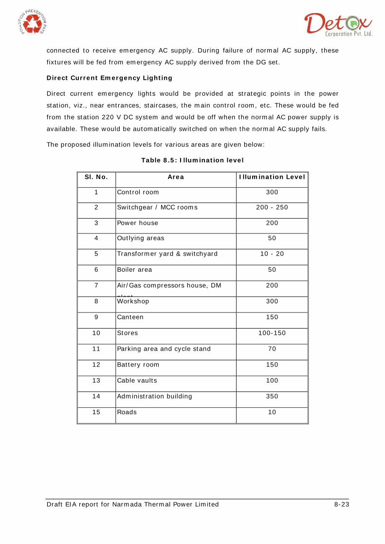
Draft EIA report for Narmada Thermal Power Limited 8-23
connected to receive emergency AC supply. During failure of normal AC supply, these
fixtures will be fed from emergency AC supply derived from the DG set.
Direct Current Emergency Lighting
Direct current emergency lights would be provided at strategic points in the power
station, viz., near entrances, staircases, the main control room, etc. These would be fed
from the station 220 V DC system and would be off when the normal AC power supply is
available. These would be automatically switched on when the normal AC supply fails.
The proposed illumination levels for various areas are given below:
Table 8.5: Illumination level
Sl. No. Area Illumination Level
1 Control room 300
2 Switchgear / MCC rooms 200 - 250
3 Power house 200
4 Outlying areas 50
5 Transformer yard & switchyard 10 - 20
6 Boiler area 50
7 Air/Gas compressors house, DM
plant
200
8 Workshop 300
9 Canteen 150
10 Stores 100-150
11 Parking area and cycle stand 70
12 Battery room 150
13 Cable vaults 100
14 Administration building 350
15 Roads 10
Draft EIA report for Narmada Thermal Power Limited 8-24
8.6 RISK ANALYSIS DUE TO STORAGE AND HANDLING OF CHLORINE
Hazards in chlorine handling and storage
8.6.1 Health hazards data
Skin:
Liquid and gas are capable of causing a burn. Remove contaminated clothing under
shower.
Eyes:
Liquid and gas are capable of causing a burn. Immediate flush with water at least for 15
minutes. Use no oils or Chemical neutralizers. Obtain medical assistance promptly.
Inhalation:
Remove from contaminated area. If breathing has ceased start artificial respiration at
once. Obtain medical assistance.
Ingestion:
Not a likely occurrence. Vomiting should be induced.
8.6.2 Environmental protection procedures
Waste disposal methods:
Chlorine gas will disperse to the atmosphere leaving no residue. Neutralizing chemicals
are caustic soda solutions, soda ash Solution and lime solution.
Protective equipment:
Requires NIOSH approved self-contained breathing apparatus and may require a fully
encapsulated suit.
8.6.3 Special protection information
Ventilation recommended:
Sufficient to control below TLV or PEL. Chlorine will collect at the floor or ground level.
Exhaust systems must be designed accordingly. Absorption or scrubber systems are
recommended.
TLV Value for chlorine: 0.5 ppm
Glove type recommended:
Non-porous, i.e. neoprene, butyl or viton.
Draft EIA report for Narmada Thermal Power Limited 8-25
Additional information:
Do not attempt to handle chlorine without previous training in Respiratory equipment for
toxic gases.
8.6.4 Transportation
Usual shipping containers:
Steel tank cars, tank trucks, ton containers, 100 and 150 pound cylinders.
Suitable storage materials/coatings:
Steel
Unsuitable:
Titanium, chrome, aluminum and reactive metals
Risk Control Measures for Chlorine Cylinders
The proposed power plant will store 3 number of 100 kg chlorine cylinders for raw water
chlorine applications. The following risk mitigation measures will be adopted during the
design phase
• Chlorine cylinders will be stored in an isolated air tight room.
• Project Proponent may consider installing fixed chlorine leak detectors. It may be
ensured that they are installed at a height of about 300mm from the ground
level, as chlorine is a heavy gas. In the event of any minor leaks chlorine detector
will activate the control valve to stop the chlorine supply to the main header.
• In order to minimize further consequences due to failure of chlorine detection and
control valve system it has been proposed to install automatic room ventilation
system which in turn should be coupled to an alkali scrubber to neutralize the
excess chlorine leaked in the chlorine tonner handling room
• Chlorine emergency kit may be procured and emergency team members trained
to use the same
• Self Contained Breathing Apparatus (SCBA) may be procured and emergency
response team members trained on the use of the same
• Eye wash fountain / emergency shower may be installed in the plant areas
• Electrical operated siren may be installed in the plant area to announce
emergency. Manually operated siren may also be provided as a back up.
• Emergency lighting (either connected to UPS or battery operated lights) may be
provided in critical plant areas
Draft EIA report for Narmada Thermal Power Limited 8-26
8.7 RISK ANALYSIS DUE TO HSD AND LDO
8.7.1 Fire & Explosion Hazard:
Fire and explosion hazards at LDO terminals may result from the presence of flammable
gases and liquids, oxygen, and ignition sources during loading and unloading activities,
and / or leaks and spills of flammable products. Possible ignition sources include sparks
associated with the buildup of static electricity, etc.
Static electricity may be generated by liquids moving in contact with other materials,
including pipes and tanks during loading and unloading of product. Oils take longer to
dissipate electric charges and hence represent a higher risk of ignition from static
electricity.
As said earlier, LDO contains hydrocarbons which are volatile and can give off vapors.
Vapor may spread along the ground and collect in low or confined areas. May also travel
to a source of ignition and flash back. Vapors may form combustible mixtures with air at
temperatures at or above the flash point.
Fire & explosion hazard due to LDO increases in presences of strong oxidizing agents
such as peroxides, nitric acid and per chlorates as LDO is highly reactive to oxidizing
agents.
8.7.2 Health hazard data
Routes of entry
Inhalation, Skin absorption, ingestion
Effects of exposure / symptoms:
Excessive inhalation Vapors cause rapid breathing, excitability, staggering, headache,
fatigue, nausea and vomiting, dizziness,
Skin contact:
Skin-dryness, cracking, irritation eyes watering, stinging and inflammation. Emergency
treatment: In case of eye or Skin contact, flush with plenty of water. Remove
Soaked clothing in case of excessive inhalation move the victim to fresh air, obtain
medical Assistance.
8.7.3 Preventive measures
Personal protective equipment:
Canister type gas mask, PVC or Rubber, Goggles giving complete protection to eyes, Eye
wash fountain with safety shower should be used as PPE.
Draft EIA report for Narmada Thermal Power Limited 8-27
Handling and storage precautions:
Do not expose to heat and naked lights, keep containers and valves closed when not in
use.
8.7.4 Emergency and first aid measures
Fire extinguishing media
Foam, Carbon dioxide, Dry Chemical Powder. Water may be used to cool fire-exposed
containers.
Unusual hazards:
It will spread along the ground and collect in sewers Exposure:
Skin contact: in case of contact with Skin flush with fresh water, remove containment
clothing.
Inhalation: in case of excessive inhalation move the victim to fresh air, If problem in
breathing give artificial respiration; give oxygen. Obtain medical assistance.
Ingestion: Give water to conscious victim to drink; do not induce vomiting.
Antidotes/Dosages: N.A.
Spills: Steps to be taken shut off leak, if safe to do so, .Keep non-involved people away
from spill site. Eliminate all sources of ignition. Prevent spill entering in to sewers, for
Major spillage contact Emergency services
Waste Disposal method: N.A.
8.8 RISK ANALYSIS FOR ASH HANDLING SYSTEM
8.8.1 Various ash discharge point in a FBC boiler are as below:
Convection bank / Economizer / Air heater / Electro static precipitator
Hopper will be provided below all these discharge points. For controlling the dust
emission in the plant due to fly-ash discharge, dense phase ash handling is envisaged. In
this system ash will be mixed with pressurized air and ash will be discharged in an ash
silo where ash and air will be separated out. Then ash will be loaded in the transport
vehicle and will be disposed of for cement plant.
8.9 OCCUPATIONAL HEALTH AND SAFETY
The Proposed plant where multifarious activities are involved during construction, erection,
testing, commissioning, operation and maintenance, the men, materials and machines are
the basic inputs. Along with the boon, the industrialization generally brings several
problems like occupational health and safety.
Draft EIA report for Narmada Thermal Power Limited 8-28
The following occupational health and safety issues are specific to proposed plant
activities:
• Physical hazards
• Heat and hot liquids
• Respiratory hazards
• Electrical hazards
• Noise
• Entrapment hazards
• Fire and explosions
Physical Hazards
Industry specific physical hazards are discussed below.
Potential physical hazards in proposed plant are related to handling of raw materials and
product; heavy mechanical transport (e.g. trucks) and work at heights (e.g. platforms,
ladders, and stairs).
Heavy Loads / Grinding & Cutting / Rolling
Lifting and moving heavy loads at elevated heights using hydraulic platforms and cranes
presents a significant occupational safety hazard. Recommended measures to prevent
and control potential worker injury include the following;
• Clear signage in all transport corridors and working areas;
• Appropriate design and layout of facilities to avoid crossover of different activities
and flow of processes;
• Implementation of specific load handling and lifting procedures, including:
• Description of load to be lifted (dimensions, weight, position of center of gravity)
• Specifications of the lifting crane to be used (maximum lifted load, dimensions)
• Train staff in the handling of lifting equipments and driving mechanical transport
devices.
• The area of operation of fixed handling equipment (e.g. cranes, elevated
platforms) should not cross above worker and pre-assembly areas;
• Material and product handling should remain within restricted zones under
supervision;
Draft EIA report for Narmada Thermal Power Limited 8-29
• Regular maintenance and repair of lifting, electrical, and transport equipment
should be conducted. Prevention and control of injuries related to grinding and
cutting activities, and use of scrap, include the following:
• Locate machine-tools at a safe distance from other work areas and from
walkways;
• Conduct regular inspection and repair of machine-tools, in particular protective
shields and safety devices / equipment;
• Train staff to properly use machines-tools, and to use appropriate personal
protection equipment (PPE).
Heat and Hot Liquid
High temperatures and direct radiation are common hazards in industries. High
temperatures can cause fatigue and dehydration. Direct radiation also poses a risk to
sight. Potential contact with hot water may occur from the cooling zone, from splashes of
hot material and from contact with hot surfaces. Recommended measures for prevention
and control of exposure to heat and hot liquids / materials include the following:
• Shield surfaces where close contact with hot equipment or splashing from hot
materials is expected;
• Implement safety buffer zones to separate areas where hot materials are handled
or temporarily stored. Rail guards around those areas should be provided, with
interlocked gates to control access to areas during operations;
• Use appropriate PPE (e.g. insulated gloves and shoes, goggles to protect against
radiation, and clothing to protect against heat radiation);
• Install cooling ventilation to control extreme temperatures;
• Implement work rotations providing regular work breaks, access to a cool rest
area, and drinking water.
Respiratory Hazards
Insulation Materials
Recommended management practices include:
• Damaged or friable material should be repaired or removed while other materials
may be monitored and managed insitu. Any handling of insulation materials
deemed to contain asbestos or any other hazardous material should only be
performed by properly trained and certified contractors and personnel following
internationally accepted procedures for their repair or removal;
Draft EIA report for Narmada Thermal Power Limited 8-30
Dust and Gas
Dust is generated in storage and handling of raw material storage. In the melting
process high temperature operations are conducted, workers may be exposed to gas
inhalation hazards.
Recommendations to prevent exposure to gas and dust include the following:
• Design facility ventilation to maximize air circulation. Outlet air shall be filtered
before discharge to the atmosphere;
• Exhaust ventilation should be installed at the significant point sources of dust and
gas emissions;
• Provide a sealed cabin with filtered air conditioning if an operator is needed in a
contaminated area;
• Provide separated eating facilities that allow for washing before eating;
• Provide facilities that allow work clothes to be separated from personal clothes,
and for washing / showering after work;
• Implement a policy for periodic health checks.
Respiratory hazard control technologies should be used when exposure cannot be
avoided with other means, such as manual operations such as grinding or use of
non-enclosed machine-tools; and during specific maintenance and repair
operations. Recommendations for respiratory protection include the following:
• Use of filter respirators when exposed to heavy dust;
• For light dust and gases, fresh-air supplied respirators should be used.
Alternatively, a complete facial gas mask (or an “overpressure” helmet) may be
used, equipped with electrical ventilation;
• For carbon monoxide (CO) exposure, detection equipment should be installed to
alert control rooms and local personnel. In case of emergency intervention in
areas with high levels of CO, workers should be provided with portable CO
detectors, and fresh-air supplied respirators.
Electrical Hazards
Workers may be exposed to electrical hazards due to the presence of heavy-duty
electrical equipment.
Draft EIA report for Narmada Thermal Power Limited 8-31
Noise
Raw and product material handling as well as the production processes themselves may
generate excessive noise levels.
Entrapment
Risk of entrapment may occur in storage areas and in particular during maintenance
operation (e.g. inside large mineral hopper). Measures to prevent burials include the
following:
• Ensure proper containment wall for mineral heaps;
• Ensure distance between heaps and transit way;
• Develop and adopt specific safety procedures for working inside hoppers (e.g.
verification systems / procedures to stop refilling belt and to close refilling hole);
• Train staff to make stable heaps and to follow procedures.
Explosion and Fire Hazards
Coal is susceptible to spontaneous combustion due to heating during natural oxidation of
new coal surfaces. Coal dust is combustible and represents an explosion hazard in coal
handling facilities.
Recommended techniques to prevent and control explosion risks due to coal dust storage
include the following:
• Coal storage times should be minimized;
• Coal piles should not be located above heat sources such as steam lines or
manholes;
• Covered coal storage structures should be made of non-combustible materials;
• Storage structures should be designed to minimize the surface areas on which
coal dust can settle, and dust removal systems should be provided;
• Ignition sources should be kept to an absolute minimum, providing appropriate
equipment grounding to minimize static electricity hazards. All machinery and
electrical equipment inside the storage area or structure should be approved for
use in hazardous locations and provided with spark-proof motors.
8.10 OTHER HAZARDS AND ITS CONTROLS
The other hazards possible at site are as given below:
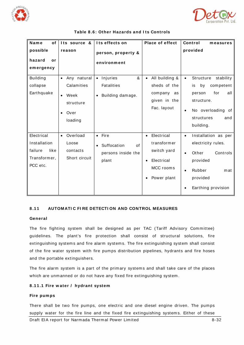
Draft EIA report for Narmada Thermal Power Limited 8-32
Table 8.6: Other Hazards and Its Controls
Name of
possible
hazard or
emergency
Its source &
reason
Its effects on
person, property &
environment
Place of effect Control measures
provided
Building
collapse
Earthquake
• Any natural
Calamities
• Week
structure
• Over
loading
• Injuries &
Fatalities
• Building damage.
• All building &
sheds of the
company as
given in the
Fac. layout
• Structure stability
is by competent
person for all
structure.
• No overloading of
structures and
building.
Electrical
Installation
failure like
Transformer,
PCC etc.
• Overload
Loose
contacts
Short circuit
• Fire
• Suffocation of
persons inside the
plant
• Electrical
transformer
switch yard
• Electrical
MCC rooms
• Power plant
• Installation as per
electricity rules.
• Other Controls
provided
• Rubber mat
provided
• Earthing provision
8.11 AUTOMATIC FIRE DETECTION AND CONTROL MEASURES
General
The fire fighting system shall be designed as per TAC (Tariff Advisory Committee)
guidelines. The plant's fire protection shall consist of structural solutions, fire
extinguishing systems and fire alarm systems. The fire extinguishing system shall consist
of the fire water system with fire pumps distribution pipelines, hydrants and fire hoses
and the portable extinguishers.
The fire alarm system is a part of the primary systems and shall take care of the places
which are unmanned or do not have any fixed fire extinguishing system.
8.11.1 Fire water / hydrant system
Fire pumps
There shall be two fire pumps, one electric and one diesel engine driven. The pumps
supply water for the fire line and the fixed fire extinguishing systems. Either of these
Draft EIA report for Narmada Thermal Power Limited 8-33
centrifugal pumps can alone deliver the required amount of water. At the rated flow, the
pressure produced by the pumps shall be adequate, at least 7 bars by the rated flow,
and at a zero flow not exceed 10 bar.
Diesel Engine
Diesel engine shall be equipped with an approved automatic auxiliary starting device
having a sufficient capacity for at least six starts of fire pump. The diesel pump shall
have a fuel tank containing sufficient fuel to enable the pump to run on full load for at
least three hours.
Jockey Pumps
An electric motor driven jockey pump of requisite capacity will maintain automatically
system pressure in the fire line. If the jockey pump can not keep the pressure the fire
pumps shall come into action automatically by the pressure drop. The fire pumps are
stopped manually.
Operation of all the fire pumps shall be automatic. Pressure switches located in the fire
water main shall sense sudden drop of pressure below set point, due to opening of any
hydrant valves, which shall provide the starting signal to the fire pumps. For stopping of
the pumps only manual arrangement shall be provided.
The run and fault alarms from the fire pumps are led to the control room. The pumps will
be located in pump house which shall be constructed by purchaser based on input from
supplier.
Toxic Gas Detector
There is no toxic gas exposure is envisaged from the proposed project hence no detector
envisages. However natural gas leakage detectors will be installed at different locations
in the premises.
Fire Water Storage Tank
The water for fire-fighting shall be stored in the fire water tank. The water capacity of
the Fire Fighting Water tank shall be 500 KL and is as per statutory requirement.
Water distribution system
Fire piping shall be of MS Class “C” with supports for above ground lines. For
underground piping GI class “C” pipes with necessary fittings will be used. The piping will
be externally painted. The codes IS1239/IS 3589 will be followed. All underground pipes
shall have cathodic protection. Sufficient number of isolation valve shall be provided to
isolate the area in case of maintenance. The diameter of the fire pipes shall be sufficient
Draft EIA report for Narmada Thermal Power Limited 8-34
for the effective use of at least two fire hoses. The pipes and hydrants will be so placed
that the fire hoses may be easily coupled to them.
Hydrants
Hydrant type Fire Protection System essentially shall consist of a network of piping and
hydrant valves- both indoor & outdoor. The distance between any two hydrants will not
be more than 45 meters. Each hydrant will be provided with a hose cabinet (mounted
along side the hydrant on a steel column, lockable type) containing two nos. of 15 M
long hoses and branch pipes/nozzles. For multi-stored building located alongside engine
hall, a wet riser tapped off from the hydrant main, shall be provided for each stair case
inside the stair case and on this riser hydrant outlet with first aid hose reel connection
shall be provided on each floor. Each hydrant shall be provided with a wall/column
mounted on hose cabinet containing two nos. of hose and branch pipe/nozzle.
The number and position of the hydrants shall be such that spray from at least two
hoses with combined jet and water fog nozzles may reach any part of the hall or
auxiliary room and spray from one combined jet and water fog nozzles may reach any
part of other places. A hydrant unit inside the power house shall consist of two hose
couplings of size DN50, both equipped with a shutoff valve. There will be two couplings
beside each other to make it possible to use the water hose and mobile foam unit
simultaneously. Some hydrants shall also to be installed on an external wall, to allow the
use of hoses outside a building.
Fire hoses shall be cotton and nylon jacket seamless woven and rot proofed material
equipped with quick couplings and adjustable water fog nozzles. Hose couplings and
nozzles throughout the fire line shall be completely interchangeable. Hose couplings shall
be made of a copper alloy or other approved material.
Hose length : 15 m
Hose diameter : 63 mm
Busting pressure test : 32 kg/cm2
Fire department connections
The fire water line will be provided with a fire department connection to allow additional
water supply from fire department. It consist of a check valve, a pipe between the fire
water line after the fire pump and outside wall and 3 inches hose connections on the
outside wall.
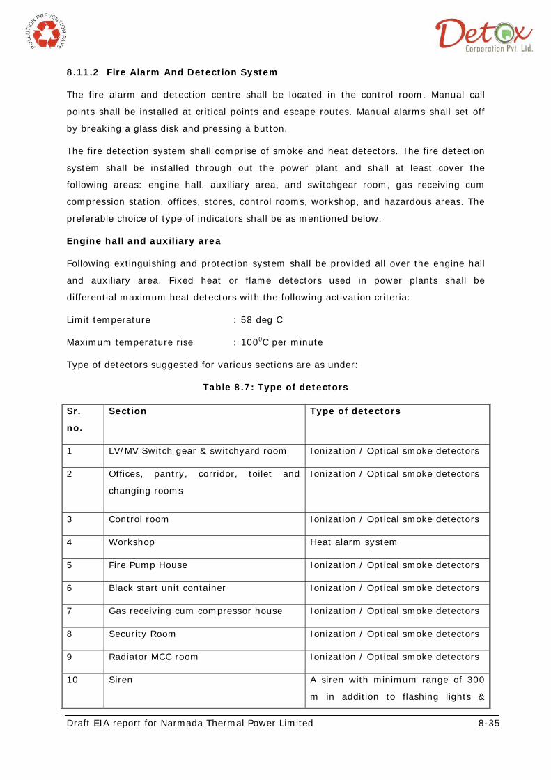
Draft EIA report for Narmada Thermal Power Limited 8-35
8.11.2 Fire Alarm And Detection System
The fire alarm and detection centre shall be located in the control room. Manual call
points shall be installed at critical points and escape routes. Manual alarms shall set off
by breaking a glass disk and pressing a button.
The fire detection system shall comprise of smoke and heat detectors. The fire detection
system shall be installed through out the power plant and shall at least cover the
following areas: engine hall, auxiliary area, and switchgear room, gas receiving cum
compression station, offices, stores, control rooms, workshop, and hazardous areas. The
preferable choice of type of indicators shall be as mentioned below.
Engine hall and auxiliary area
Following extinguishing and protection system shall be provided all over the engine hall
and auxiliary area. Fixed heat or flame detectors used in power plants shall be
differential maximum heat detectors with the following activation criteria:
Limit temperature : 58 deg C
Maximum temperature rise : 1000C per minute
Type of detectors suggested for various sections are as under:
Table 8.7: Type of detectors
Sr.
no.
Section Type of detectors
1 LV/MV Switch gear & switchyard room Ionization / Optical smoke detectors
2 Offices, pantry, corridor, toilet and
changing rooms
Ionization / Optical smoke detectors
3 Control room Ionization / Optical smoke detectors
4 Workshop Heat alarm system
5 Fire Pump House Ionization / Optical smoke detectors
6 Black start unit container Ionization / Optical smoke detectors
7 Gas receiving cum compressor house Ionization / Optical smoke detectors
8 Security Room Ionization / Optical smoke detectors
9 Radiator MCC room Ionization / Optical smoke detectors
10 Siren A siren with minimum range of 300
m in addition to flashing lights &
Draft EIA report for Narmada Thermal Power Limited 8-36
alarm bells shall be provided in DG
building.
8.12 SAFETY ORGANIZATION AND ITS ACTIVITIES
8.12.1 Construction and Erection Phase
A qualified and experienced safety officer will be appointed. The responsibilities of the
safety officer includes identification of the hazardous conditions and unsafe acts of
workers and advise on corrective actions, conduct safety audit, organize training
programs and provide professional expert advice on various issues related to
occupational safety and health. He is also responsible to ensure compliance of Safety
Rules/ Statutory Provisions. In addition to employment of safety officer by Plant, every
contractor, who employs more than 250 workers, will also employ one safety officer to
ensure safety of the worker, in accordance with the conditions of contract.
8.12.2 Operation and Maintenance Phase
When the construction is completed the posting of safety officers would be in accordance
with the requirement of Factories Act and their duties and responsibilities would be as
defined there of.
8.12.3 Strengthening of HSE and Meeting by Safety and quality circle
In order to fully develop the capabilities of the employees in identification of hazardous
processes and improving safety and health, safety and quality circles would be
constituted in area of work. The circle normally will meet for about an hour fortnight.
8.12.4 Safety Training
A full fledged training center will be set up at the plant. Safety training would be
provided by the Safety Officers with the assistance of faculty members called from
Corporate Center, Professional Safety Institutions and Universities. In addition to regular
employees, limited contractor labors would also be provided safety training. To create
safety awareness safety films would be shown to workers and leaflets would be
distributed. Some precautions and remedial measures proposed to be adopted to
prevent fires are:
• Compartmentation of cable galleries, use of proper sealing techniques of cable
passages and crevices in all directions would help in localizing and identifying the
area of occurrence of fire as well as ensure effective automatic and manual fire
fighting operations;
Draft EIA report for Narmada Thermal Power Limited 8-37
• Reliable and dependable type of fire detection system with proper zoning and
interlocks for alarms are effective protection methods for conveyor galleries;
• House keeping of high standard helps in eliminating the causes of fire and regular
fire watching system strengthens fire prevention and fire fighting; and Proper fire
watching by all concerned would be ensured.
• Tie up will be made with emergency services like local fire station, hospitals,
emergency van etc during operation phase. The emergency telephone numbers
will be displayed at different points within the plant premises and at the entry exit
gates.
8.13 HEALTH AND SAFETY MONITORING PLAN
All the potential occupational hazardous work places would be monitored regularly for air
quality, noise level and illumination level (during day and night). The health of
employees working in these areas would be monitored once in a year for early detection
of any ailment due to exposure to hazardous chemicals. First aid centres and medical
centre should be provided. Transportation arrangement should be provided in case of
emergency.
8.13.1 Do’s and Don’ts checklist
Do’s:
Preventive maintenance:
1) Prepare preventive maintenance schedule for all major equipments. 2) Ensure that preventive maintenance is carried out as per schedule. 3) Identify persons who will carry out preventive maintenance. 4) Provide necessary training to those persons to carry out preventive maintenance
safely and effectively. 5) Mention due date for preventive maintenance on each equipment. 6) In form concern department prior to start preventive maintenance. 7) Wear proper PPE’s prior to start preventive maintenance.
Strengthening of HSE:
1) Appoint safety personnel for safety related activities. 2) Form safety committee to review safety related issues and recommend to higher
management for implementation. 3) Periodic health checkup for the employees. 4) Ensure proper lighting inside work premises. 5) Provide proper sign boards for PPE’s 6) Implement proper submit system s to carry out hot work in flammable area and
work at height.
Draft EIA report for Narmada Thermal Power Limited 8-38
Mfg and utility staff for safety related measures:
1) Mfg and utility staff should provide proper training for operations to be carried out.
2) Adequate number of PPE’s to be provided to mfg and utility staff. 3) Ensure proper super vision in mfg and utility areas.
Don’ts:
Preventive maintenance:
1) Don’t start preventive maintenance without proper PPE. 2) Don’t start preventive maintenance without approval of concern department.
Strengthening of HSE:
1) Don’t allow smoking inside the premises 2) Don’t allow person without shoes inside the plant area. 3) Don’t allow to run vehicle above speed limit inside the premises.
Mfg and utility staff for safety related measures:
1) Don’t allow unknown person in plant area without permission.
Draft EIA report for Narmada Thermal Power Ltd. 9-1
Chapter 9 Disaster Management Plan
9.1 GENERAL
Disaster is an undesirable happening of such magnitude and nature, which can
adversely affect man, material and environment. Risk assessment forms an integral
part of “Disaster Management”. Any major or a number of minor failures could lead
to an accident taking a heavy toll of human life and affecting the production
target considerably.
Disaster management has assumed significant role in the gas based power plant
operations. Disasters are major accidents, which cause wide spread disruption of
human and commercial activities. Disaster can be defined as a sudden
occurrence of impacts of greater magnitude to affect normal pattern of life in the
plant and/or vicinity, causing extensive damage to life and property. Normally, the
community absorbs common accidents, but disasters are major accidents and
community cannot absorb within its own resources. Most of the disasters, natural or
technological (man-made) have sudden onset and give very short notice or no time to
prevent the occurrence.
Disaster has the potential to cause serious injury or loss of life, both inside and
outside the works. It would normally require the assistance of outside emergency
services to handle it effectively. Although the emergency may be caused by a number
of different factors, e.g. plant failure, human error, earthquake, vehicle crash or
sabotage etc., it will normally manifest itself in power plant operation as three basic
forms: fire, explosion or toxic release.
It is therefore, necessary to ensure safety and reliability of any new plant, through a
systematic study of industrial installations to identify possible failures and prevent their
occurrence before the disasters.
9.2 PURPOSE AND SCOPE OF DMP
In carrying out the preliminary Risk Analysis, the stress is given to Maximum Credible
Accident (MCA) analysis and the resulting DMP include the following:
• On-Site Emergency Plan
• Off-site Emergency Plan
• Safety Review Check Plan
• Accident Reporting
Draft EIA report for Narmada Thermal Power Ltd. 9-2
9.3 CAUSES OF DISASTER
Disastrous incident could be a local one causing damage to plant, equipment and
material only or additionally affecting the persons working in the plant/industry or if
more serious, affecting the neighboring environment including human population. The
first two categories can be termed as “On- site Emergency” and the last one as an “Off-
site Emergency”. There are number of factors that can be considered as causes for
disastrous situation or emergencies.
A good process technology has to be engineered properly by following accepted
standards in design, if the hazards are to be minimized. Improper sizing of plant and
equipment, inadequate schemes, faulty choice of material of construction may lead to
unsafe conditions. Risk evaluation, Hazard analysis and Hazard & operability will be
emphasized made mandatory when engineering the proposed project.
9.4 DISASTER CONTROL PHILOSOPHY
The principal strategy of Disaster Management Plan of proposed project is prevention of
the identified major hazards. And since these hazards can occur only in the event of
loss of containment, one of the key objectives of technology selection, project
engineering, construction, commissioning and operation is Total and Consistent Quality
assurance. It is committed to this philosophy right from the conceptual stage of the
proposed project. The second control strategy adopted for potential emergencies is
minimization of operation inventories of hazardous substances both in process plants as
well as in storage limits of viability of continuous operation. In the proposed power plant
there is no storage of natural gas. The gas will be procured through pipeline from the
nearest available sources.
And another control measure that will be adopted is early detection of any accidental
leak and activation of as well structured, resourced and rehearsed Off -Site Emergency
Plan to intercept the incident with speed and ensure safety to employees, operating
plants, public and environment as a matter of priority.
9.5 DISASTER CONTROL PLAN
Design stage considerations:
For the proposed power plant major emergency situation can arise mainly from fire in
coal storage area, leakage in HSD and risk due to accidental chlorine leakage. From
the analysis of the vulnerable zones the following actions will be taken during design
stage:
Draft EIA report for Narmada Thermal Power Ltd. 9-3
Chlorine Storage
• Chlorine installations will be sited at a sufficient distance (25 m minimum)
from public roads to reduce the risk of in the event of an accident.
• Protective barriers will be installed wherever necessary.
• The chlorine unloading area will be on reasonably level ground with adequate
surrounding space providing good access from different directions.
• Adequate lighting covering all escape routes will be provided and the provision
of emergency lighting will be also available.
• Automatic Chlorine gas leak detectors will be provided.
• The chlorine pipeline in the area will be properly routed so as to minimize the
risk of damage from collision by the tanker, other vehicle or mobile equipment.
• Leakage of liquid chlorine are potentially more dangerous than leaks of
gaseous chlorine, hence the proper storage system will designed so that sources
of leakage of liquid are reduced to a minimum.
• All liquid chlorine storages will be installed in a bund, which is impervious to liquid
chlorine. The bund should be capable of taking the contents of the largest single
storage. Sump will be connected to an alkali scrubber to provided
neutralization in an event of emergency. Provision will be provided for
removal of rain water over bund wall, through valves in the bund.
• In an event of toxic release from the tonner all the people within 550 m of the
prevailing wind direction will be advised to run perpendicular to the wind
direction.
• Adequate means will be provided for evacuation of the critical segment of the
population to a safer place.
• Maintenance personnel will be equipped with protective equipment’s to minimize
the risk of exposure in case of an accident.
Coal storage:
• Air circulating within a coal pile should be restricted as it contributes to heating;
compacting helps seal air out.
• Moisture in coal contributes to spontaneous heating because it assists the
oxidation process and should be limited to 3%.
Draft EIA report for Narmada Thermal Power Ltd. 9-4
• Coal having high moisture content should be segregated and used as quickly as
possible. Efforts should be made to keep stored coal from being exposed to
moisture.
• Dry coal shall be kept dry and shall be not exposed to any rain during storage
period. This concerns what is known as the heat-of-wetting;
• Drying coal is an endothermic process [heat is absorbed] and lowers the
temperature of the coal. Wetting (or gaining moisture) is an exothermic process
and the liberated heat can accelerate the spontaneous heating of the coal.
• Following the "first in, first out" rule of using stock reduces the chance for hot
spots by helping preclude heat buildup for portions of stock which remain
undisturbed for a long term. The design of coal storage bins is important in this
regard.
• A high ambient temperature aids the spontaneous heating process.
• Use coal as quickly as practicable. The longer large coal piles are allowed to sit,
the more time the spontaneous process has to work.
• The shape and composition of open stockpiles can help prevent fires. Dumping
coal into a big pile with a trestle or grab bucket can lead to problems. Rather,
coal should be packed in horizontal layers, which are then leveled by scraping and
compacted by rolling. This method helps distribute the coal evenly and thus
avoids breakage and segregation of fine coal. Segregation of coal particles by size
should be strenuously avoided, as it may allow more air to enter the pile and
subsequent heating of finer sizes.
• Properly inspect, test and maintain installed fire protection equipment.
• Maintain an update pre-fire plan and encourage regular visits to coal facilities by
the site or local emergency response force.
9.6 FIRE FIGHTING ARRANGEMENT
Fire detection and fire fighting systems were discussed in detail in chapter 8 in section
8.11.
Fire Services Personnel
Fire service shall be manned by trained fire safety personnel. Fire services department
shall have adequate number of safety equipment for use during emergency. The list of
safety appliances is as follows:
Gas Mask
Canisters Alkali Suit
Draft EIA report for Narmada Thermal Power Ltd. 9-5
Asbestos Suit
Fire Proximity Suit
BA Set
Electric Gloves (for 15000 volts)
Hydraulic Tool
Telephone
Emergency Ladder, etc.
9.7 SAFETY AND PERSONAL PROTECTIVE APPLIANCES
Safety and personal protective appliances shall be provided in adequate numbers and
shall be distributed in different sections according to requirement. A list of such
appliances available in the plant is given in the Table 9.1.
Table 9.1: List of Proposed Safety Equipment
Sl.No. Equipment Nos. GAS MASK 01. Carbon Monoxide Adequate Nos. 02. Chlorine - do - BREATHING APPARATUS 01. Compressed Air - do - 02. Airline respirator - do - OTHERS 01. Pneupac Resuscitator - do - 02. Combustible gas indicator/explosimeter - do - 03. Gas Detector (Dragger Pump) - do - 04. Safety Belts - do - 05. Alkali/Acid Suit - do - 06. Asbestos Suit - do - 07. Hand Gloves etc. - do - 08. Gum Boots - do - 09. Safety Shoes - do - 10. Eye Goggles - do -
9.8 EMERGENCY ACTION PLAN
The emergency action plan consists of:
• First information;
• Responsibilities of Work Incident Controller;
• Responsibilities of Chief Incident Controller;
• Responsibilities for Declaration of Emergency;
• Responsibilities for Emergency Communication Officer;
• Responsibilities of key personnel;
Draft EIA report for Narmada Thermal Power Ltd. 9-6
• Responsibilities and action to be taken by essential staff and various teams during
emergency; and
• Responsibilities for All Clear Signal.
9.8.1 First Information
The first person who observes/identities the emergencies will inform by shouting and by
telephone to the Shift Engineer and Fire Station about the hazard. The Shift Engineer will
inform to Works Incident Controller, Chief Incident Controller and also telephone
operator, who shall communicate it to all key personnel.
9.8.2 Responsibilities of Work Incident Controller (WIC)
The Work Incident Controller on knowing about an emergency immediately will rush to
the incident site and take overall charge and inform the same to Chief Incident Controller
(Chief Executive). On arrival, he will assess the extent of emergency and decide if major
emergency exists and inform the communication officer accordingly. His responsibilities
will be to ensure compliance to the duties listed below.
9.8.3 Responsibilities of Chief Incident Controller (CIC)
The Chief Executive, who is also the Chief Incident Controller, will assume overall
responsibilities for the factory/storage site and its personnel in case of any emergency.
His responsibilities are to:
1. Assess the magnitude of the situation and decide if staff needs to be evacuated from
their assembly point to identified safer places. Declare on-site/off-site emergency.
2. Exercise direct operational control over areas other than those affected.
3. Undertake a continuous review of possible developments and assess in consultation
with key personnel as to whether shutting down of the plant or any section of the plant
and evacuation of personnel are required.
4. Laison with senior officials of Police, Fire Brigade, Medical and Factories Inspectorate
and provide advice on possible effects on areas out side the factory premises.
5. Look after rehabilitation of affected persons on discontinuation of emergency.
6. Issue authorized statements to news media, and ensures that evidence is preserved for
inquiries to be conducted by the statutory authorities.
9.8.4 Responsibilities For Declaration Of Major Emergency
• Making the emergency known inside the plant
Draft EIA report for Narmada Thermal Power Ltd. 9-7
The major emergency will be made known to everyone inside the plant by blowing the
alarm. Separate alarms to warn different types of major emergencies such as fire and
explosion or toxic gas escape are provided. Public address system is also available
throughout the plant.
Announcement will be made by the concerned official/interpreter in local language.
Similarly announcement for termination of the emergency will also be announced.
9.8.5 Responsibilities of Emergency Communication Officer (ECO)
On hearing the emergency alarm he will proceed to Emergency Control Center. He will:
• Report to Chief Incident Controller and Work Incident Controller and maintain
contact with them.
• On information received from the WIC of the situation, recommending if
necessary, evacuate the staff from the assembly points.
• Identify suitable staff to act as runner or messenger who is listed in the Essential
staff, between him and the Works Incident Controller if the telephone and other
system of communication fail due to any reason.
• Maintain inventory of items in the emergency control center.
• Contact local meteorological office to receive early notification of changes in
weather condition in case of gas leak and prolonged action.
• Maintain a log of incidents.
• Keep in constant touch with happenings at the emergency site and with WIC
9.8.6 Key Personnel
Apart from Works Incident Controller and Chief Incident Controller, other works
personnel will have key role to play in providing advice and in implementing the
decisions made by the Chief Incident Controller. The key personnel include:
A. Sr. Supdts./Engineer-in-charge responsible for
• Operation
• Electrical Maintenance
• Mechanical maintenance
• C&I
• Chemical
B. Head of Personnel and Officers connected with IR and Labour Welfare
C. Head (Technical Service)
Draft EIA report for Narmada Thermal Power Ltd. 9-8
9.8.7 Responsibilities of Key Personnel
• Department Heads
The departmental heads will provide assistance as required. They will decide which
members of their departments are required at the incident site.
• Chief Personnel Manager
He will:
a) Report to Work Incident Controller;
b) Ensure that all non-essential workers in the affected areas are evacuated to assembly
points in consultation with the Chief Incident Controller;
c) Receive reports from nominated persons from assembly points, and pass on the
absence information services;
d) Keep liaison with other coordinators to meet the requirements of services such as
materials, security management, transportation, medical, canteen facilities etc. as
required during emergency;
e) Be in constant touch with the Chief Incident Controller and feed him correct information
of the situation;
f) Give information to press, public and authorities concerned on instructions from the
CIC/WIC;
g) Ensure that casualties receive adequate attention at medical center and arrange
required additional help and inform relatives of the injured;
h) Arrange to inform public on Radio and TV about evacuation etc.; and
i) Arrange TV coverage on handling emergency.
• In-Charge
On knowing about an emergency, he will report to CIC and assist him in all activities. He
will also liaison with all teams.
• Medical Officer
Medical Officer will render medical treatment to the injured and if necessary will shift the
injured to nearby Hospitals. He will mobilize extra medical help from outside if
necessary.
• Safety Officer
On hearing the Emergency alarm he will proceed to main entrance/main gate. He will:
Draft EIA report for Narmada Thermal Power Ltd. 9-9
a. Make sure that all safety equipment are made available to the emergency teams;
b. Arrange to control the traffic at the gate and the incident area;
c. Direct the security staff to the incident site to take part in emergency operations under
his guidance and supervision;
d. Evacuate the persons in the plant or in the nearby areas as advised by WIC after
arranging the transport through the Transport in-charge;
e. Allow only those people who are associated with handling emergency;
f. Maintain law and order in the area, if necessary seek the help of police; and
g. Maintain communication with CIC/WIC and ECO.
• Fire Officer
On hearing the emergency, he will reach the fire station and arrange to sound the alarm
as per the type of emergency in consultation with WIC, He will:
a. Guide the fire fighting crew i.e. firemen and trained plant personnel and shift the fire
fighting facilities to the emergency site. Adequate facilities will be made available;
b. Take guidance of the WIC for fire fighting as well as assessing the requirement of
outside help;
c. Maintain communication with WIC, CIC and ECO.
• Transport -in-Charge
On hearing the emergency alarm he will immediately report to WIC. He will:
a. Ensure availability of auto base vehicles for evacuation or other duties, when asked for;
and
b. Make all arrangements regarding transportation.
9.9 EMERGENCY CONTROL CENTRE
An emergency control centre shall be provided at a safe place from where Chief
Emergency Co-ordinator shall function for ON-SITE emergency. The Emergency Control
Centre (ECC) shall be provided with following;
• Adequate number personal protective equipment,
• Alarm and communication network (Siren, local as well as P&T Telephone, Public
Address system etc.),
• Route map,
Draft EIA report for Narmada Thermal Power Ltd. 9-10
• Map of the factory & surrounding areas, evacuation routes, fire hydrant network
and other important information
• Details of fire hydrant system
• Copy of detailed Disaster Management Plan, where names, telephone numbers of
the response team members and their responsibilities are clearly written as well
as names and telephone numbers of key personnel from outside agencies and
district authorities, Fire Station, nearby Hospitals and doctors should be made
available.
• First aid kit,
• Material safety data sheets of chemicals
Assembly Point
Assembly points shall be set up near to the likely hazardous event sites where pre-
designated persons from the disaster response team should assemble and meet the
Site Incident controller. This may be regarded as Site Incident Control Room where
Incident Controller will receive instruction and furnish information to the Chief
Emergency coordinator. The site incident control room shall be provided with efficient
communication system, adequate personal protective equipment, copy of Disaster
Management Manual etc.
Emergency Shelter
Emergency shelter places shall be chosen sufficiently away from likely affected site.
Employees who are not in the emergency management team shall be asked to take
shelter. The place is chosen such that the employees taking shelter are not affected by
fire, explosion and release of toxic gases. More than one emergency shelter shall be
designated so that proper shelter point can be chosen depending on wind direction and
other factors.
Wind Socks
Windsocks shall be provided on the top of tall buildings to indicate the wind direction.
Fire Station
A fire station with fire water tender shall be provided.
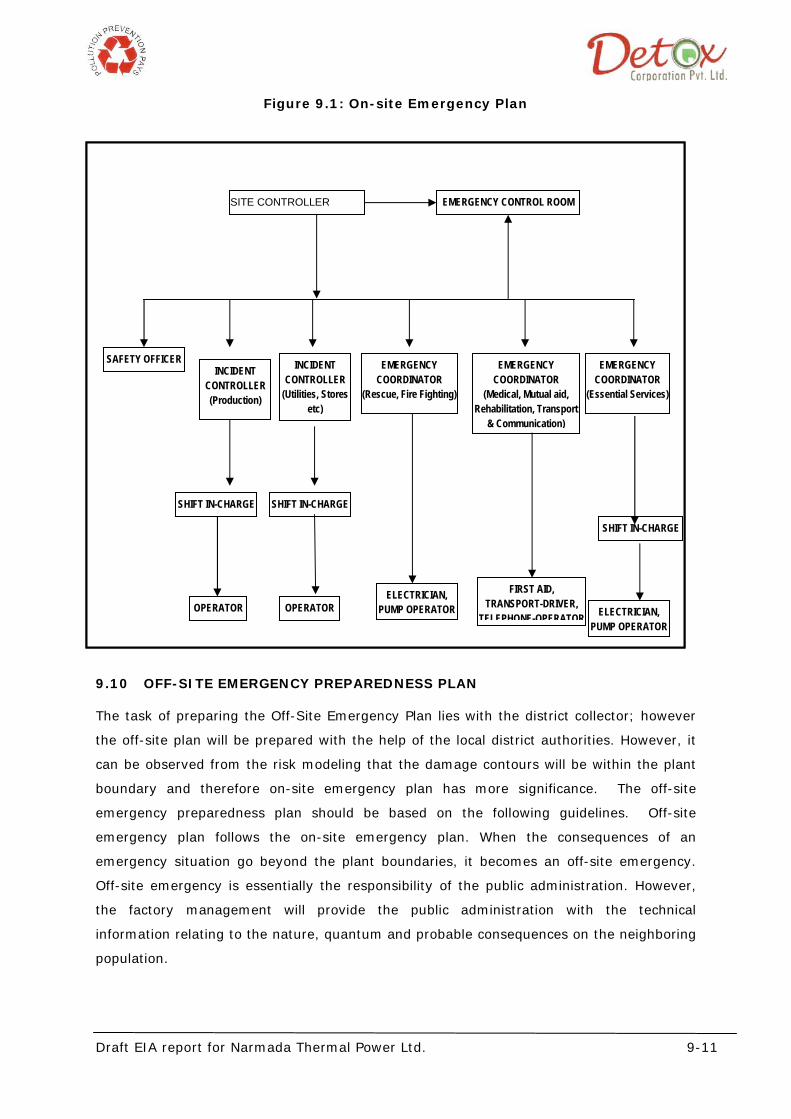
Draft EIA report for Narmada Thermal Power Ltd. 9-11
Figure 9.1: On-site Emergency Plan
9.10 OFF-SITE EMERGENCY PREPAREDNESS PLAN
The task of preparing the Off-Site Emergency Plan lies with the district collector; however
the off-site plan will be prepared with the help of the local district authorities. However, it
can be observed from the risk modeling that the damage contours will be within the plant
boundary and therefore on-site emergency plan has more significance. The off-site
emergency preparedness plan should be based on the following guidelines. Off-site
emergency plan follows the on-site emergency plan. When the consequences of an
emergency situation go beyond the plant boundaries, it becomes an off-site emergency.
Off-site emergency is essentially the responsibility of the public administration. However,
the factory management will provide the public administration with the technical
information relating to the nature, quantum and probable consequences on the neighboring
population.
SITE CONTROLLER EMERGENCY CONTROL ROOM
SAFETY OFFICER INCIDENT
CONTROLLER (Production)
EMERGENCY COORDINATOR
(Rescue, Fire Fighting)
EMERGENCY COORDINATOR
(Medical, Mutual aid, Rehabilitation, Transport
& Communication)
EMERGENCY COORDINATOR
(Essential Services)
SHIFT IN-CHARGE
SHIFT IN-CHARGE
INCIDENT CONTROLLER
(Utilities, Stores etc)
SHIFT IN-CHARGE
OPERATOR OPERATOR ELECTRICIAN, PUMP OPERATOR
ELECTRICIAN, PUMP OPERATOR
FIRST AID, TRANSPORT-DRIVER,
TELEPHONE-OPERATOR
Draft EIA report for Narmada Thermal Power Ltd. 9-12
The off-site plan in detail will be based on those events, which are most likely to occur, but
other less likely events, which have severe consequence, will also be considered. Incidents
which have very severe consequences yet have a small probability of occurrence should
also be considered during the preparation of the plan. However, the key feature of a good
off-site emergency plan is flexibility in its application to emergencies other than those
specifically included in the formation of the plan.
The roles of the various parties who will be involved in the implementation of an off-site
plan are described below. Depending on local arrangements, the responsibility for the off-
site plan should be either rest with the works management or, with the local authority.
Either way, the plan should identify an emergency co-ordinating officer, who would take the
overall command of the off-site activities. As with the on-site plan, an emergency control
center should be setup within which the emergency co-ordinating officer can operate.
An early decision will be required in many cases on the advice to be given to people
living "within range" of the accident - in particular whether they should be evacuated or
told to go indoors. In the latter case, the decision can regularly be reviewed in the event
of an escalation of the incident. Consideration of evacuation may include the following
factors:
a. In the case of a major fire but without explosion risk only houses close to the fire
are likely to need evacuation, although a severe smoke hazard may require this to
be reviewed periodically;
b. If a fire is escalating and in turn threatening a store of hazardous material, it might
be necessary to evacuate people nearby, but only if there is time; if insufficient time
exists, people will be advised to stay indoors and shield themselves from the fire;
c. For release or potential release of toxic materials, limited evacuation may be
appropriate down wind if there is time. The decision would depend partly on the
type of housing "at risk". Conventional housing of solid construction with windows
closed offers substantial protection from the effects of a toxic cloud, while shanty
house, which can exist close to factories, offer little or no protection.
The major difference between releases of toxic and flammable materials is that toxic clouds
are generally hazardous down to much lower concentrations and therefore hazardous over
greater distances. Also, a toxic cloud drifting at, say 300 m per minute covers a large area
of land very quickly. Any consideration of evacuation should take this into account.
Although the plan will have sufficient flexibility built in to cover the consequences of the
range of accidents identified for the on-site plan, it will cover in some detail the handling of
the emergency to a particular distance from each major hazard works.
Draft EIA report for Narmada Thermal Power Ltd. 9-13
9.10.1 Aspects proposed to be considered in the Off-Site Emergency Plan
The main aspects, which will be included in the emergency plan, are:
• Organization
Details of command structure, warning systems, implementation procedures, emergency
control centers. Names and appointments of incident controller, site main controller, their
deputies and other key personnel.
• Communications
Identification of personnel involved, communication center, call signs, network, and lists of
telephone numbers.
• Specialized knowledge
Details of specialist bodies, firms and people upon whom it may be necessary to call e.g.
those with specialized chemical knowledge, laboratories.
• Voluntary organizations
Details of organizers, telephone numbers, resources etc.
• Chemical information
Details of the hazardous substances stored or procedure on each site and a summary of the
risk associated with them.
• Meteorological information
Arrangements for obtaining details of whether conditions prevailing at the time and
whether forecasts.
• Humanitarian arrangements
Transport, evacuation centers, emergency feeding treatment of injured, first aid,
ambulances and temporary mortuaries
• Public information
Arrangements for (a) dealing with the media press office; (b) informing relatives, etc.
• Assessment of emergency plan
Arrangements for: (a) collecting information on the causes of the emergency; (b) reviewing
the efficiency and effectiveness of all aspects of the emergency plan.
Draft EIA report for Narmada Thermal Power Ltd. 9-14
9.10.2 Role of the Emergency Co-ordinating Officer
The various emergency services should be coordinated by an emergency co-ordinating
officer (ECO), who will be designated by the district collector. The ECO should liase closely
with the site main controller. Again depending on local arrangements, for very severe
incidents with major or prolonged off-site consequences, the external control should be
passed to a senior local authority administrator or even an administrator appointed by the
central or state government.
9.10.3 Role of the Local Authority
The duty to prepare the off-site plan lies with the local authorities. The emergency planning
officer (EPO) appointed should carry out his duty in preparing for a whole range of different
emergencies within the local authority area. The EPO should liase with the works, to obtain
the information to provide the basis for the plan. This liaison should ensure that the plan is
continually kept upto date.
It will be the responsibility of the EPO to ensure that all those organizations which will be
involved off site in handling the emergency, know of their role and are able to accept it by
having for example, sufficient staff and appropriate equipment to cover their particular
responsibilities. Rehearsals for off-site plans should be organized by the EPO.
9.10.4 Role of Police
Formal duties of the police during an emergency include protecting life and property and
controlling traffic movements.
Their functions should include controlling bystanders evacuating the public, identifying the
dead and dealing with casualties and informing relatives of death or injury.
9.10.5 Role of Fire Authorities
The control of a fire should be normally the responsibility of the senior fire brigade officer
who would take over the handling of the fire from the site incident controller on arrival at
the site. The senior fire brigade officer should also have a similar responsibility for other
events, such as explosions and toxic release. Fire authorities in the region should be
appraised about the location of all stores of flammable materials, water and foam supply
points and fire-fighting equipment. They should be involved in on-site emergency
rehearsals both as participants and, on occasion, as observers of exercises involving only
site personnel.
9.10.6 Role of Health Authorities
Health authorities, including doctors, surgeons, hospitals, ambulances and so on, will have
a vital part to play following a major accident and they will form an integral part of the
Draft EIA report for Narmada Thermal Power Ltd. 9-15
emergency plan. For major fires, injuries should be the result of the effects of thermal
radiation to a varying degree and the knowledge and experience to handle this in all but
extreme cases may be generally available in most hospitals. For major toxic releases, the
effects vary according to the chemical in question, and the health authorities should be
apprised about the likely toxic releases from the plant which will unable then in dealing with
the aftermath of a toxic release with treatment appropriate to such casualties.
Major off-site incidents are likely to require medical equipment and facilities additional to
those available locally and a medical “mutual aid “scheme should exist to enable the
assistance of neighboring authorities to be obtained in the event of an emergency.
9.10.7 Role of Government Safety Authority
This will be the factory Inspectorate available in the region. Inspectors are likely to want to
satisfy themselves that the organization responsible for producing the off-site plan has
made adequate arrangements for handling emergencies of all types including major
emergencies. They may wish to see well documented procedures and evidence of exercise
undertaken to test the plan.
In the event of an accident, local arrangements regarding the role of the factory inspector
will apply. These may vary from keeping a watching brief to a close involvement in advising
on operations in case involvement in advising on operations. In cases where toxic gases
may have been released, the factory inspectorate may be the only external agency with
equipment and resources to carry out tests. The off-site emergency organization chart for
major disaster is shown below:
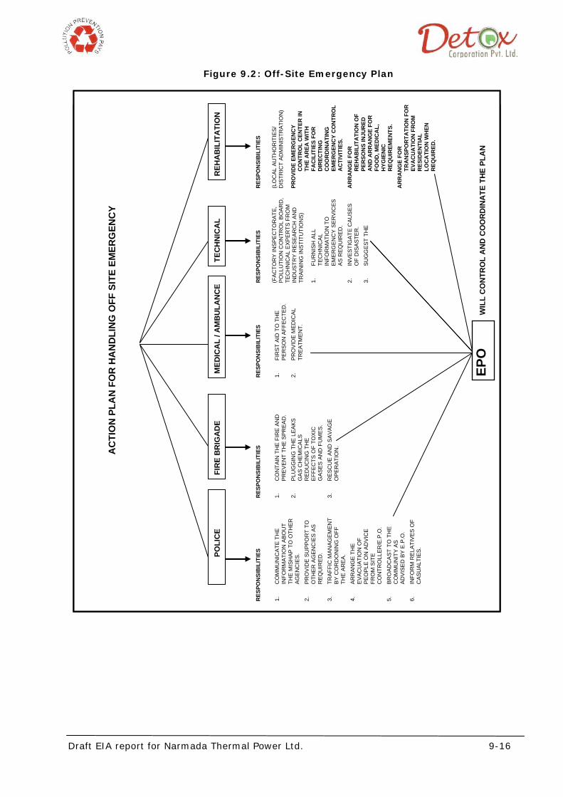
Draft EIA report for Narmada Thermal Power Ltd. 9-16
Figure 9.2: Off-Site Emergency Plan
AC
TIO
N P
LAN
FO
R H
AN
DLI
NG
OFF
SIT
E EM
ERG
ENC
Y
P
OLI
CE
FIR
E B
RIG
AD
E M
EDIC
AL
/ AM
BU
LAN
CE
TEC
HN
ICA
L R
EHA
BIL
ITA
TIO
N
RES
PON
SIB
ILIT
IES
(L
OC
AL A
UTH
OR
ITIE
S/
DIS
TRIC
T AD
MIN
ISTR
ATIO
N)
PRO
VID
E EM
ERG
ENC
Y
CO
NTR
OL
CEN
TER
IN
THE
AR
EA W
ITH
FA
CIL
ITIE
S FO
R
DIR
ECTI
NG
C
OO
RD
INA
TIN
G
EMER
GEN
CY
CO
NTR
OL
AC
TIVI
TIES
. A
RR
AN
GE
FOR
R
EHA
BIL
ITA
TIO
N O
F PE
RSO
NS
INJU
RED
A
ND
AR
RA
NG
E FO
R
FOO
D, M
EDIC
AL,
H
YGIE
NIC
R
EQU
IREM
ENTS
. A
RR
AN
GE
FOR
TR
AN
SPO
RTA
TIO
N F
OR
EV
AC
UA
TIO
N F
RO
M
RES
IDEN
TIA
L LO
CA
TIO
N W
HEN
R
EQU
IRED
.
RES
PON
SIB
ILIT
IES
(F
ACTO
RY
INSP
ECTO
RAT
E,
PO
LLU
TIO
N C
ON
TRO
L B
OA
RD
, TE
CH
NIC
AL E
XPER
TS F
RO
M
IND
UST
RY
RES
EAR
CH
AN
D
TRAI
NIN
G IN
STIT
UTI
ON
S)
1.
FUR
NIS
H A
LL
TEC
HN
ICAL
IN
FOR
MAT
ION
TO
EM
ERG
ENC
Y SE
RVI
CES
AS
REQ
UIR
ED
.
2.
INVE
STIG
ATE
CAU
SES
O
F D
ISAS
TER
.
3.
SUG
GES
T TH
E
RES
PON
SIB
ILIT
IES
1.
FIR
ST A
ID T
O T
HE
PER
SON
AFF
ECTE
D.
2.
PRO
VID
E M
EDIC
AL
TREA
TMEN
T.
RES
PON
SIB
ILIT
IES
1.
CO
NTA
IN T
HE
FIR
E AN
D
PREV
ENT
THE
SPR
EAD
.
2.
PLU
GG
ING
TH
E LE
AKS
GAS
CH
EMIC
ALS
RED
UC
ING
TH
E EF
FEC
TS O
F TO
XIC
G
ASES
AN
D F
UM
ES.
3.
RES
CU
E AN
D S
AVA
GE
OPE
RAT
ION
.
RES
PON
SIB
ILIT
IES
1.
CO
MM
UN
ICAT
E TH
E IN
FOR
MAT
ION
ABO
UT
THE
MIS
HAP
TO
OTH
ER
AGEN
CIE
S.
2.
PRO
VID
E SU
PPO
RT
TO
OTH
ER A
GEN
CIE
S AS
R
EQU
IRED
.
3.
TRAF
FIC
MAN
AGEM
ENT
BY
CO
RD
ON
ING
OFF
TH
E AR
EA.
4.
ARR
ANG
E TH
E EV
ACU
ATIO
N O
F PE
OPL
E O
N A
DVI
CE
FRO
M S
ITE
CO
NTR
OLL
ER/E
.P.O
.
5.
BRO
ADC
AST
TO
TH
E C
OM
MU
NIT
Y AS
AD
VISE
D B
Y E.
P.O
.
6.
INFO
RM
REL
ATIV
ES O
F C
ASU
ALTI
ES.
EPO
W
ILL
CO
NTR
OL
AN
D C
OO
RD
INA
TE T
HE
PLA
N
Draft EIA report for Narmada Thermal Power Ltd. 9-17
9.11 SAFETY & EMERGENCY PLAN
Safety of both men and material during construction and operation stages is of
concern to industries. The preparedness of an industry for the occurrence of possible
disasters is known as emergency plan. The disaster in power plant may occur due to
leakage of hazardous chemicals like chlorine, collapse of structures and fire/explosion
etc. Keeping in view the safety requirements during construction, operation and
maintenance phases, and the gas based power plant would formulate safety policy with
respect to the following requirements:
• To allocate sufficient resources to maintain safe and healthy conditions at work.
• To take steps to ensure that all known safety factors are taken into account
in the design, construction, operation and maintenance of plants, machinery and
equipment.
• To ensure that adequate safety instructions are given to all employees.
• To provide wherever necessary protective equipment, safety appliances and
clothing, and to ensure their proper use.
• To inform employees about materials, equipment or processes used in their work,
which are known to be potentially hazardous to health or safety.
• To keep all operations and methods of work under regular review for making
necessary changes from the point of view of safety in the light of experience and up
to date knowledge.
• To provide appropriate instruction, training, retraining and supervision in health
and safety, first aid and to ensure that adequate awareness is given to these
matters.
• To ensure proper implementation of fire prevention and an appropriate firefighting
service together with training facilities for personnel involved in this service.
• To ensure that professional advice is made available wherever potentially
hazardous situations exist or might arise.
• To organize collection, analysis and presentation of data on accident, sickness
and incident involving personal injury or cause of sickness with a view to taking
corrective, remedial and preventive action.
• To promote through the established machinery, joint consultation in health and
safety matters to ensue effective participation by all employees.
• To publish/notify regulations, instructions and notices in the common language of
employees.
Draft EIA report for Narmada Thermal Power Ltd. 9-18
• To prepare separate safety rules for each type of occupation/process involved in a
power station.
• To ensure regular safety inspection by a competent person at suitable intervals
of all buildings, equipment, work places and operation
9.12 PRE-EMERGENCY ACTIONS
The proposed preventive and pre-emptive measures are as follows:-
• Ensure implementation of Disaster Planning.
• Ensure that all drafted for emergency undergo regular training and are prepared
for tackling emergency/disaster.
• Ensure that Mock Drills are performed under simulated emergency condition at
regular intervals to assess the strength and weaknesses of the response team/plan.
• Ensure awareness among employees through regular training.
• Ensure good liaison with all agencies and industries in the neighborhood for getting
help if situation arises.
• Ensure adequate stock of safety, personal protective appliances in good working
condition.
• Ensure awareness amongst public in the neighboring areas.
• Medical Services
The doctors in the nearby hospitals should be trained for treatment of personnel affected
by chlorine gas leakage. Necessary apparatus and drugs should also be available in first
aid post and in State Hospitals and also other Nursing Homes nearby. Manager (HR-
Welfare) should have good liaison with authorities of nearby hospitals and Nursing
Homes as well as doctors outside so that help may be available when required. Qualified
safety officer and medical officer will be appointed.
9.13 TRANSPORT AND COMMUNICATION
Ambulance Van will be available inside power plant premises. The disaster management
cell will have the contact number of nearby hospitals or nursing home with Ambulance
facility to call them in case of emergency.
Draft EIA for Narmada Thermal Power Limited 10-1
Chapter-10 Summary & Conclusion
The proposed plant is located at Survey no.134,135A,135B,137,138, Village: Padaria,
Taluka: Vagra, District: Bharuch, Gujarat. The site is approachable by the site is well
connected through an existing village road to the state Highway.
10.1 LAND AVAILABILITY AND REQUIREMENT
The project is proposed to be located in about 122 acres of land located at Survey
no.134,135A,135B,137,138, Village: Padaria, Taluka: Vagra, District: Bharuch, Gujarat.
10.2 FUEL REQUIREMENT, STORAGE & HANDLING SYSTEM
Coal shall be used as major fuel. The detail of fuel consumption along with its source is
given in the table below:
Table 10.1: Raw material details
FUEL Quantity Source Transportation
Indian Coal 1.53 million TPA From Indian mines Road Network by
Trucks/ Tankers.
Imported coal 1.144 million TPA From Indonesian
mines
Transport through Dahej
port via NH 8A & SH 50
LDO/HSD 2010 KL HPCL / IBPL Road Network by Road
tankers.
10.3 WATER AVAILABILITY AND REQUIREMENT
Water requirements of the project will be met through Luwara Branch canal by Sardar
Sarovar Narmada Nigam Ltd.
10.4 ENVIRONMENT IMPACT ASSESSMENT STUDY
In order to identify the impacts due to construction and operation of Narmada Thermal
Power Limited and draw an Environmental Management Plan, a detailed Environmental
Impact Assessment (EIA) Study has been undertaken through M/S Detox Corporation
Private Limited, Surat. The environmental disciplines studied include meteorology, air
quality, water quality and water use, soils, land-use, demography and socio-economics, and
noise. The study was conducted during summer season (March 2011 to May 2011).
Draft EIA for Narmada Thermal Power Limited 10-2
10.5 ANTICIPATED ENVIRONMENTAL IMPACTS AND MITIGATION MEASURES
10.5.1 Land Use:
The proposed site, comprising of 122 acre of land and is without any human settlement. The
proposed site where the plant is to be located has been presented in the Google earth map
in chapter 1, Figure 1.1, page 1-5 of the report.
10.5.2 Water Use and Hydrology:
Project proponent will draw its entire water requirement for the project from Luwara Branch
canal by Sardar Sarovar Narmada Nigam Ltd.
10.5.3 Demography and Socio-economics:
The proposed site is located in rural area without any human settlement. There will be no
displacements and no problems related to Rehabilitation and Resettlement. However project
would create the employment opportunity for the local community which inturn lead to
socio-economic development of the region.
10.5.4 Air Quality
The maximum predicted incremental ground level concentrations (GLCs) for particulate
matter, SOx and NOx will be 3.025 μg/m3, 3.979 μg/m3 and 2.474 μg/m3 respectively in
North West direction.
The incremental concentration for and NOx and SOx will be at distance of 2.692 Km and
that for Particulate matter will be at distance of 1.118 Km.
10.5.5 Water Quality
While developing the water system for the project, utmost care has been taken to maximize
the recycle/ reuse of effluents and minimize effluent quantity. The effluents from main plant
cooling tower blow down (Boiler Blow down and DM Plant Regeneration Waste) shall be fully
treated and will be reused.
10.5.6 Noise:
The major noise generating sources during the construction phase are vehicular traffic,
construction equipment like, dozer, scrapers, concrete mixers, cranes, generators, pumps,
compressors, rock drills, pneumatic tools, vibrators etc. The operation of these equipments
will generate noise ranging between 75 - 90 dB (A).
However, workers within the construction area and plant area may be affected due to high
noise levels. Adequate protective measures in the form of ear- muffs / ear plugs/ masks
Draft EIA for Narmada Thermal Power Limited 10-3
shall be provided to such persons, which will minimise / eliminate such adverse impacts. In
addition, reduction in noise levels shall also be achieved through built-in design
requirements to produce minimum noise, proper lay out design, adding the sound barriers,
use of enclosures with suitable absorption material etc. Provision of green belt and
afforestation will further help in reducing the noise levels.
10.6 DISASTER MANAGEMENT PLAN
The EIA Report includes a Disaster Management Plan covering elements of emergency
planning like organization, communication, coordination, procedure, accident reporting,
safety review checklist, on-site emergency plan and off-site emergency plan. A Disaster
Management Plan (DMP) for the project has already been prepared and to be implemented
for the proposed project, specifying responsibilities at various levels to be discharged in case
of an emergency. The DMP at site shall be strengthened suitably based on recommendation
of DMP included in EIA Report.
10.7 PROJECT BENEFITS
The major project benefits are as mentioned below:
• Increase in employment opportunity in skilled, semi-skilled and un-skilled
categories.
• Increase in employment/ self employment avenues in service sector.
• Development of support infrastructure such schools, roads improve the
livelihood and social status of the local peoples
For the proposed project, the project proponent is committed to implement social
welfare measures as part of Corporate Social Responsibility plan as the part of the
proposed project and has proposed to implement various community development
programs.
10.8 ENVIRONMENT MANAGEMENT PLAN
An Environment Management Plan for Construction and operation phases of the project has
been prepared. An Environment Management cell shall be created to strengthen and
monitoring of the implementation of the environmental management plan for the project.
10.9 ENVIRONMENT MONITORING PLAN
The main attributes for which monitoring shall be carried out are as below:
1. Ambient air Quality
Draft EIA for Narmada Thermal Power Limited 10-4
2. Stack Emission
3. Wastewater Quality
4. Noise Level
Conclusions:
Based on the above, it has been concluded that by adopting a robust environmental
management plan and risk mitigation measures as presented in the EIA report, the
proposed project would exhibit very insignificant environmental impacts. However, the
implementation of proposed massive plantation, green belt area and community
development programs under CSR activities would bring significant positive impacts to the
entire region.
Hence it is being requested to State Expert Appraisal Committee, Gujarat for considerations
of awarding Environmental Clearance for the project as per the provisions of EIA Notification
and its amendments there on.
Draft EIA report for Narmada Thermal Power Limited 11-1
Chapter 11 Disclosure of Consultants
11.1 GENERAL INFORMATION
Name of Organization : Detox Corporation Pvt. Ltd.
Address : 3rd Floor, K.G. chambers, Udhna Darwaja, Ring
road, Surat- 395 002
Telephone Nos. : +91-261- 2351248 ,2326181
Fax : +91-261- 2354068
Email : [email protected]
11.2 VISION AND BUSINESS ETHICS
“Company’s long established philosophy – to provide QUALITY SERVICES through integrated
Environmental Solutions delivered within the client’s schedule. “
11.3 KEY FACTS
1995 Laid Foundation Stone of Firm. Activities covered fabrication & equip. supply
1997 Developed Turnkey execution.
1997 Developed core competence for conducting Environment Audits.
1998 Developed a Full Fledged Laboratory
1998 Construction of ETP’s & STP’s
2000 Developed core competence for preparation of EIA Study Reports
2002 Expansion and Modernization of Lab & Office.
2004 Certified for ISO 9001: 2000 (QMS)
2004 Established First Branch Office at Gandhidham, Kutch
2005 Tie up with Ozmotech, Australia for Converting Waste Plastic to Diesel
2006 Foundation laid for setting up a Total Hazardous Waste Management site at
Kutch, Gujarat
11.4 ACCREDITATIONS & REGISTRATIONS
• ISO 9001-2000 certification through DLIQ Certification affiliated to JAZ –ANZ of
Australia.
• NABL (National Accreditation Board for Testing & Calibration) Certificate No: T-
1635,validity 16/07/2011
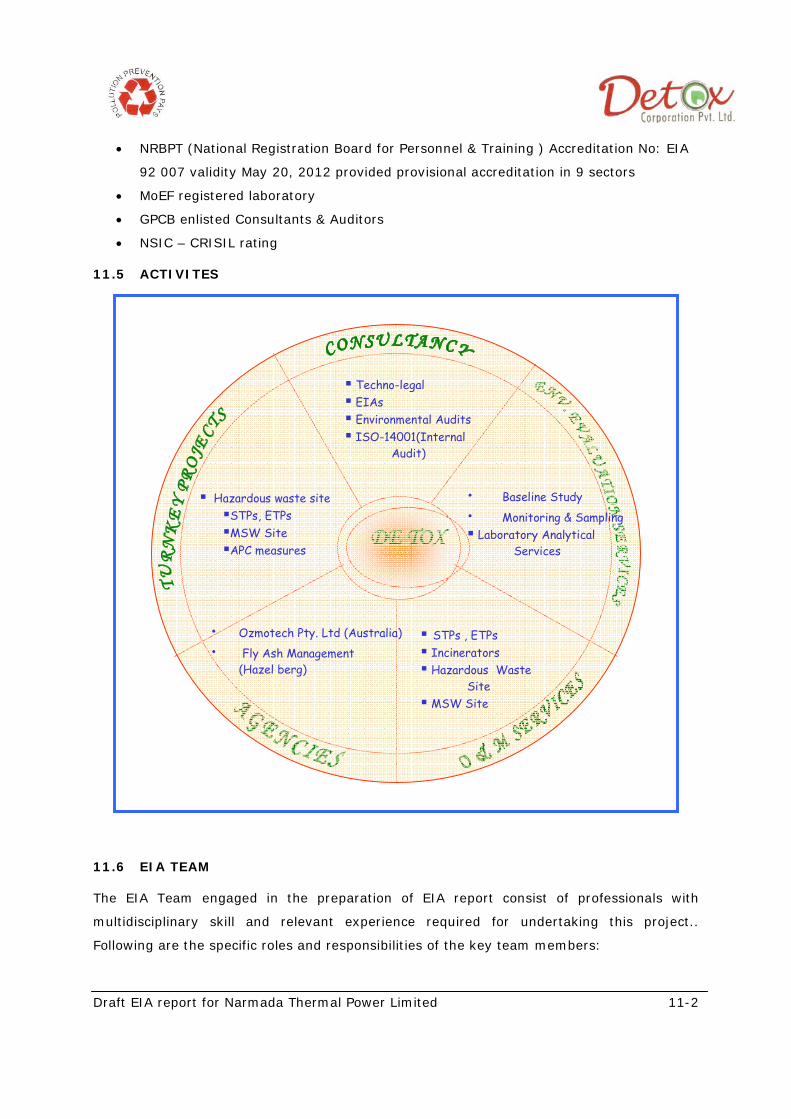
Draft EIA report for Narmada Thermal Power Limited 11-2
• NRBPT (National Registration Board for Personnel & Training ) Accreditation No: EIA
92 007 validity May 20, 2012 provided provisional accreditation in 9 sectors
• MoEF registered laboratory
• GPCB enlisted Consultants & Auditors
• NSIC – CRISIL rating
11.5 ACTIVITES
11.6 EIA TEAM
The EIA Team engaged in the preparation of EIA report consist of professionals with
multidisciplinary skill and relevant experience required for undertaking this project..
Following are the specific roles and responsibilities of the key team members:
DE TOX
Techno-legal EIAs Environmental Audits ISO-14001(Internal
Audit)
• Baseline Study • Monitoring & Sampling
Laboratory Analytical Services
Hazardous waste site STPs, ETPs MSW Site APC measures
• Ozmotech Pty. Ltd (Australia) • Fly Ash Management
(Hazel berg)
STPs , ETPs Incinerators Hazardous Waste
Site MSW Site
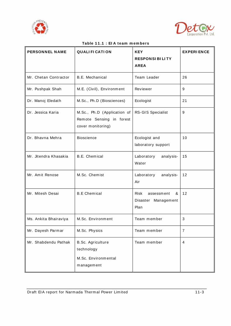
Draft EIA report for Narmada Thermal Power Limited 11-3
Table 11.1 : EIA team members
PERSONNEL NAME QUALIFICATION KEY
RESPONSIBILITY
AREA
EXPERIENCE
Mr. Chetan Contractor B.E. Mechanical Team Leader 26
Mr. Pushpak Shah M.E. (Civil), Environment Reviewer 9
Dr. Manoj Eledath M.Sc., Ph.D (Biosciences) Ecologist 21
Dr. Jessica Karia M.Sc., Ph.D (Application of
Remote Sensing in forest
cover monitoring)
RS-GIS Specialist 9
Dr. Bhavna Mehra Bioscience Ecologist and
laboratory support
10
Mr. Jitendra Khasakia B.E. Chemical Laboratory analysis-
Water
15
Mr. Amit Renose M.Sc. Chemist Laboratory analysis-
Air
12
Mr. Mitesh Desai B.E Chemical Risk assessment &
Disaster Management
Plan
12
Ms. Ankita Bhairaviya M.Sc. Environment Team member 3
Mr. Dayesh Parmar M.Sc. Physics Team member 7
Mr. Shabdendu Pathak B.Sc. Agriculture
technology
M.Sc. Environmental
management
Team member 4

Annexure 1
Lay out map
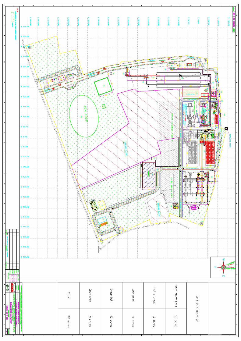

Annexure 2
Letter from DoEF regarding CRZ applicability