chapter 26 advanced rechargeable batteries introduction
TRANSCRIPT

Chapter 26 Advanced Rechargeable Batteries Introduction
by Paul C. Butler and Sandra E. Klassen
Commercial applications for advanced rechargeable batteries are constantly increasing. These applications include electric vehicles, large scale energy storage at electric utilities, storage of electrical energy produced by renewable energy resources such as solar or wind generators, and consumer electronics. Commercially available batteries are not able to meet the performance and/or cost requirements of many of these applications. To be successful, advanced battery technology need different combinations of high energy and power densities, long life, low cost, and little or no maintenance. In addition, completely safe operation must be assured.
26.1 PERFORMANCE REQUIREMENTS FOR ADVANCED RECHARGEABLE BATTERIES
26.1.1 Electric Vehicle Batteries
The major advantages of substantial use of electric vehicles are reduced dependence on fossil fuels and improvement of the environment. Energy from electric utilities or renewable sources would be used for battery charging. Electric vehicle batteries require (1) high gravimetric and volumetric energy densities to provide adequate vehicle driving range, (2) high power density to provide acceleration, (3) long cycle fife with no maintenance, and (4) low cost. The midterm battery development program being conducted by the United States Advanced Battery Consortium (USABC) is directed toward achieving commercialization of electric vehicles which are competitive with existing internal combustion vehicles by 1998. Advanced batteries being developed under the long-term USABC program are projected for commercialization starting in 2002. The USABC is a partnership between General Motors Corporation, Ford Motor Company, and Chrysler Corporation with participation by the Electric Power Research Institute and several utilities. The USABC is funded jointly by the industrial companies and the US Department of Energy. The USABC criteria for performance of electric vehicle batteries are shown in Table 26.1.1 A typical cycle for a Dynamic Stress Test (DST) for electric vehicle batteries is shown in Figure 26.1.2 The DST simulates the pulsed power charge (negative percentage) and discharge (positive percentage) environment of electric vehicle applications and is based on the Federal Urban Driving Schedule automotive test regime. The power levels are based on the maximum rated discharge power capability of the cell or battery under test. Vehicle range on a single discharge can be projected from the
Page 1

number of repititions a battery can complete on the DST before reaching its discharge cutoff criteria. This test provides more accurate cell/battery performance and life data than constant current testing because it more closely approximates the application requirements.
26.1.2 Electric Utility Applications
The use of battery energy storage in utility applications allows the efficient use of inexpensive base-load energy to meet peak shaving and other applications which reduces utility costs and permits compliance with strict environmental regulations. Batteries for electric utility applications require: (1) low first cost, (2) high reliability when operated in MWh-size systems at 2000 V or more, and (3) high volumetric energy and power densities. Recent analyses have determined that bartery energy storage can benefit all sectors of modern utilities: generation, transmission, distribution, and end-use. The use of battery systems for generation load-leveling alone cannot justify the cost of the system. However, when a single battery system is used for multiple, compatible applications, such as frequency regulation and spinning reserve, the system economics are predicted to be very favorable. The battery energy-power requirements of batteries for typical electric utility applications are shown in Table 26.2.9 A simplified test regime simulating a frequency regulation/spinning reserve application is illustrated in Fig. 26.2.4 The frequency regulation/spinning reserve test profile simulates these two utility applications on a subscale battery in order to predict performance, life, and thermal effects. Charge (positive power) and discharge (negative power) vary according to a specified regime and provide a realistic environment for batteries used in these applications.
Commercially available lead-acid batteries can satisfy the requirements for certain utility energy storage applications and are being used in several demonstration projects world-wide. The use of advanced batteries offers still greater potential for reduced cost and could enable market opportunities to be enhanced. These opportunites result from the predicted advantages of advanced batteries for lower cost, smaller system footprint, no maintenance, and high reliability when used with highly variable duty cycles.
In Japan, development of advanced secondary battery systems for electric utility applications has been carried out since 1980 as a part of the "Moonlight Project."6 Development on four systems proceeded through 60 kW - class modules, and 1 MW pilot plants were built for two systems: sodium/sulfur and zinc/bromine. Testing was satisfactorily concluded in March of 1992 with 76% energy efficiency (21 1 cycles) for sodium/sulfur and 66% energy efficiency ( I 58 cycles) for zinc/bromine. Areas for further research were identified, and improvements in reliability, maintainability, compactness, and cost reduction are expected to yield systems which are practical for utility applications.

26.1.3 Renewable Applications
Battery storage is beneficial with solar, wind, and other renewable generation systems where the energy source is intermittent. The battery is charged when the source is generating energy. This energy is stored in the battery which can then be discharged when the source is not available. Operating characteristics vary widely depending on application. For photovoltaic systems, typical appiications include village power, telemetry, telecommunications, remote homes, and lighting. Operating characteristics for photovoltaic systems are shown in Table 26.3.6 Detailed requirements are being developed, and considerations such as high energy efficiency, low self-discharge, low cost, long cycle and calendar life, and no maintenance are important.
26.1.4 Consumer Electronics
The demand for batteries for portable electronics such as wrist watches, calculators, photographic and video equipment, and computers is steadily increasing and is expected to be a substantial market for advanced rechargeable batteries. Recent progress in the miniaturization of electronics has resulted in a demand for batteries which weigh less and have a greater energy density per volume of battery. Also important are storage life, reliability, safety, and cost. Presently nickel/cadmium and sealed lead-acid batteries are the principal rechargeable technologies being used; however, other technologies such as lithium/polymer electrolyte are projected to meet future needs for compact, high energy density batteries for portable electronics. Table 26.4 shows examples of portable electronic applications along with nominal voltages and load ranges for each application.8
26.2 TYPES AND CHARACTERISTICS OF ADVANCED RECHARGEABLE BATTERY SYSTEMS
Organizations such as the US Department of Energy, the automotive industry, the Electric Power Research Institute (EPRI), the International Lead Zinc Research Organization (ILZRO), and battery manufacturers are supporting development of a diverse group of battery technologies in order to meet the requirements described in the previous section. These activities cab be categorized as follows:
1. Near-term activities to improve the performance of existing conventional technologies for use within the next few years.
2. Mid-term activities to complete the development of those advanced battery technologies that are not commercialized but, with necessary progress, can be introduced to the market within 5-10 years.

3. Long-term activities to develop new electrochemical systems offering the potential of higher energy and power, but which require significant development before commercialization.
Several test facilities are in existence for the evaluation of battery systems for these applications. Batteries at all stages of development are tested at Argonne National Laboratory, Idaho National Engineering Laboratory, Lawrence Berkeley National Laboratory, and Sandia National Laboratories. Certain tests are conducted at the Naval Weapons Support Center in Crane, Indiana. Specialized tests for utility batteries are conducted at the Modular Generation Test Facility owned by Pacific Gas and Electric Company.
The major battery technologies that have been considered for electric vehicle (EV), utility energy storage (UES), and renewable energy storage (RES) applications are listed in Table 26.5. Table 26.6 lists organizations that are working on specified technologies, and comparative data for rechargeable battery technologies are given in Table 26.7.
26.3 NEAR-TERM RECHARGEABLE BATTERIES
The major candidates for near- term applications are those rechargeable battery technologies which are commercially available today. Of these technologies, lead-acid is the most widely used and economical. It is being used in both mobile and stationary applications. Its main disadvantage is low specific energy. Lead- acid batteries with improved performance are being developed for electric vehicles by the Advanced Lead- Acid Battery Consortium (ALABC) which is funded by ILZRO and lead- acid battery manufacturers.
See Table 26.5.
Nickei/cadmium batteries are also being used in electric vehicles and offer good power density, long life, and fast recharge. The specific energy of nickel/cadmium batteries is somewhat higher than lead-acid batteries, but nickel/cadmium costs significantly more. T h e cost of nickel/cadmium batteries may be reduced by implementation of mass manufacturing and increased recycling. Recent developments such as plastic bonded electrodes and nickel foam electrodes promise to improve battery performance and possibly reduce cost.
Nickel/iron batteries are another demonstrated technology in mobile and industrial applications. They are rugged, have long life, and offer specific energy comparable to other nickel batteries. They suffer from poor low temperature performance, high self- discharge, and significant gassing (and consequent watering) during operation. The cost of these batteries is similar to other nickel batteries.
Page 4

Nickel/hydrogen and nickel/metal hydride batteries are similar in composition and performance. Nickel/hydrogen batteries have been used in satellite applications and are highly reliable, have long lives, and are very expensive. Nickel/metal hydride batteries are under intensive development and are comparable to nickel/cadmium batteries in cost. Lifetimes for nickel/metal hydride batteries are still limited, but there is promise for significant improvement.
Nickel/zinc batteries have moderate specific energy and power and have received intensive development over the years. The cycle life of nickel/zinc batteries has been limited to 200-300 cycles due to zinc electrode failure. Recent developments in improved zinc electrodes have renewed interest in this technology and work is in progress that shows promise to increase battery life significantly.
Finally, secondary zinc/silver oxide batteries have been used in electric vehicle applications. This high performance battery is very costly and has a very short lifetime. Because of these problems, little development work is in progress at this time, but the technology is commercially available for specialized, high value applications.
The U. S. Department of Energy has tested a number of technologies for electric vehicle applications, and a Ragone plot comparing these technologies is shown in Figure 26.3.
26.4 ADVANCED RECHARGEABLE BATTERIES - GENERAL CHARACTERISTICS
The advanced rechargeable batteries can be classified into three main kinds: aqueous electrolyte systems, high temperature systems, and ambient temperature lithium batteries. Each kind is discussed in the following text.
26.4.1 Aqueous Electrolyte Systems
Aqueous electrolyte battery systems have the advantage of operating close to ambient temperature. Nevertheless, complex system design and circulation of electrolyte are often needed to meet performance objectives. Three main categories of aqueous electrolyte systems exist: zinc/halogen, redox flow, and metal/air.
The ziiic/bronzine baftei’y technology is being developed for both electric vehicle and stationary energy storage applications. The system offers good specific energy and design flexibility, and battery stacks can be made from low cost and readily available materials using conventional manufacturing processes, Bromine is stored remotely as a second phase polybromide complex which is circulated during discharge. Remote storage limits

self-discharge during standby periods. An added safety benefit of the complexed polybromide is greatly reduced bromine vapor pressure compared to that of pure bromine. More information can be found in Chapter xx.
Another zinc/halogen system, the zinc/chlorine battery, was the subject of development during the mid-70s to late-80s. A more detailed summary is presented here because a separate chapter on this technology is not included in this handbook. Early work involved both electric vehicle and stationary energy storage app1ications;ll however, work in the mid to late 80s focused on utility batteries. Cell construction is comb-type bipolar, and the negative electrodes (zinc) are made of dense graphite, whereas the positive electrodes (chlorine) are made of porous graphite. Figures 26.4 and 26.5 show schematics of the battery system on charge and on discharge, respectively. On charge, a single electrolyte, composed of aqueous zinc chloride, is pumped (Pl) via line E through the porous positive electrode and past the dense negative electrode, which produces chlorine and metallic zinc. The chlorine gas flows through line C to pump P2 where chlorine combines with chilled water, supplied by line W, to form chlorine hydrate which then enters the store via line H. The water in the store is chilled by heat exchange between lines W and R. On discharge, electrolyte flows through line D which warms the store, which in turn decomposes the chlorine hydrate and produces chlorine gas. The gas flows through line G, dissolves in electrolyte, and is delivered to the battery stack for electrochemical reaction. Separators are not used since the solubility of chlorine in the electrolyte is low. Hydrogen evolution occurs at the zinc electrode; thus, the battery system also includes a fluorescent lamp to convert hydrogen, in the presence of chlorine gas, to hydrogen chloride.
In the United States, Energy Development Associates (EDA), in conjunction with the Electric Power Research Institute and the U. S. Department of Energy, focused on development of the zinc/chlorine battery for stationary energy storage applications during the early to mid-1980s.12 Both 10 kW and 100 kW units were built and tested for this program, and EDA also designed a 2 MW, 6 MWh system as an electric utility demonstration unit. This system, designated as FLEXPOWER, was composed of sixteen 125 kW modules, and in 1986 a 125 kW prototype was successfully tested.13 The prototype delivered 148 kW dc, 437 kWh dc with a DC to DC efficiency of 66,690. Overall the zinc/chlorine technology was viewed as a complicated system, however, and funds have not been available to build a pilot plant to test the FLEXPOWER design.
Development of, zinc/chlorine battery technology also took place in Japan during the 1980s as part of the "Moonlight Project" whose goal was to construct and test advanced battery utility energy storage pilot plants.'* The Japanese developed a method to store chlorine in a chilled organic solvent which, together with other improvements, improved the battery energy efficiency to 80% in a 10 kW ~ystern.1~ The positive porous graphite electrode was also improved to increase the rate of reaction at this electrode.16 A 60 kW

battery was built in 1987, and testing showed a DC to DC energy efficiency of 76.7%. A 1 MW system was designed based on sixteen 60 kW modules in series,17 but was not built. Parallel development of three other advanced battery technologies was also a part of the "Moonlight Project," and in 1988 the sodium/sulfur and zinc/bromine technologies were chosen to advance to the 1 MW pilot plant stage because they were judged to be more compact and energy efficient.14
A second category of aqueous electrolyte systems is the redox flow battery system, and work has been done to develop it for stationary energy storage applications. This handbook does not include a separate chapter on this technology, and it is summarized here. Although the system is capable of long life, the energy density is low.18
The electrochemical reactions occur in solution and carbon felts are used as inert current collectors. Two solutions are required--one for each electrode. The iron and chromium couples are commonly used- -on discharge the negative electrolyte solution contains chromium ions which are oxidized from the +2 to the +3 state, and the positive electrolyte contains iron ions which are reduced from the +3 state to the +2 state. Both reactions are reversible, although the chromium reaction requires a catalyst. The counter ion is chloride, and both electrolyte solutions contain HCI as a supporting electrolyte. An ion selective membrane is used to separate the iron and chromium solutions.
A schematic of a redox flow system is shown in Figure 26.6. The construction of the cell stacks is bipolar and may include trim cells which are on open circuit a t the beginning of discharge but are needed to boost the voltage as it begins falling in the main cell stack during discharge. One cell is left on open circuit to monitor the state of charge. A redox flow battery system also includes rebalance cells to either recombine hydrogen that is formed at the chromium electrode during charge or supply hydrogen to correct for air oxidation of chromium and iron ions. The electrolyte solutions are stored remotely in tanks and are pumped through the cells when needed. The capacity of the redox flow system depends on the size of the storage tanks. The volume of electrolyte needed is large and results in a low energy density for this technology.
In the early 1980s an ambient temperature 1 kW, 13 kWh system was built, and testing showed the concept of a redox flow battery was fea~ible.1~ Further work showed that the electrochemical performance of the chromium couple could be improved by operating at 65°C; however, the separator could not prevent mixing of the metal ions, and so a mixed- reactant mode of operation was conceived in which the electrolyte solutions in the discharged state were identical. A typical electrolyte composition was 1 M Feci2, 1 M CrCls, and 2-3 N HCI. Although coulombic efficiency was lower with the mixed electrolyte, low resistance membranes could be used which allowed current densities up to 80 mA/cm2 and energy efficiencies of more than 80%. A bismuth catalyst for the chromium electrode was also developed for operation at 65°C and replaced the gold/lead
P q e 7

catalyst used at 25°C. A final report for this project was published in 1984, but despite improvements, the technology was judged to be too complicated for practical use.
In Japan, development of redox flow technology was also included as part of the "Moonlight Project" in the 1980s.14 Improvements during the mid-80s included new electrode material, a more efficient rebalancing system, and a reduction in the requirement for pumping power.20Jl ' These improvements allowed an 81.7% DC to DC energy efficiency during an 8 hour charge/8 hour discharge for a 10 kW (80 kWh) battery. The system energy efficiency, including losses due to pumping, rebalandng, and heating, was 76.8%. A 60 kW battery was built in 1989 at the Tatsumi Substation for the Kansai Electric Power Company.22 A mixed reactant mode of operation was used, a safer rebalance system was incorporated, and electrode area was doubled. Initial tests showed battery energy efficiencies of 8344%. A 1 MW system was designed,20 but the redox flow technology was not chosen to advance to the 1 MW pilot plant ~ t a g e . 1 ~
A third category of aqueous electrolyte systems is nzefal/air, usually intended for electric vehicle uses. This is a battery system composed of a metal negative electrode, oxygen positive electrode,. and aqueous potassium hydroxide electrolyte. The aluminum/air system has a high theoretical specific energy, but the anode reactions are not reversible, thus aluminum/air batteries need to be recharged mechanically by replacing the electrode. More information on metal/air batteries can be found in Chapter XX .
26.4.2 High Temperature Systems
The high temperature systems operate in the range of 160-500°C and have high energy density and high specific power compared to most conventional ambient temperature systems. The negative electrode material is an alkali metal, such as lithium or sodium, which has a high voltage and electrochemical equivalence. Aqueous electrolytes can not be used because of the chemical reactivity of water with alkali metals. Molten salt or solid electrolytes that require high temperature are used instead. Benefits are high ionic conductivity, which is needed for high power density, and insensitivity to ambient temperature conditions. Nevertheless, high operating temperatures also increase the corrosiveness of the active materials and cell components and thereby shorten the life of the battery. Also, thermal insulation is needed to maintain operating temperatures during standby periods. The main high temperature battery systems are the sodium/beta and Iithium/iron sulfide systems.
The sodium/befa buffery system includes designs based on either the sodium/sulfur or sodium/metal chloride chemistries. The sodium/sulfur technology has been in development for over 20 years and ceils are now being produced on a pilot plant scale. Sodiunlsulfur batteries are candidates for electric vehicle and stationary energy storage
Pnge 8

applications, Sodium/sulfur technology is also considered a likely successor to nickel/hydrogen technology for aerospace applications because sodium/sulfur batteries have two to three times the specific energy of nickel/hydrogen batteries. Sodium/nickel chloride is a relatively new variation of the sodium/beta technology and is being developed mainly for electric vehicle applications. Sodium/sulfur and sodium/metal chloride technologies are similar in that sodium is the negative electrode material and beta"-alumina ceramic is the electrolyte. The solid electrolyte serves as the separator and produces 100% coulombic efficiency. Applications are needed in which the battery is operated regularly. Sodium/nickeI chloride cells have a higher open circuit voltage, can operate at lower temperature, and contain a less corrosive positive electrode than sodium/sulfur cells. Nevertheless, sodium/nickel chloride cells are projected to be moKe expensive and have lower power density than sodium/sulfur cells. More information about both technologies is included in Chapter xx.
The Zithium/iron sulfide baltery system is another high temperature system and must be operated above 400°C so that the salt mixture (LiCI-KCI) used as an electroIyte remains molten. The negative electrode is lithium which is alloyed with aluminum or silicon, and the positive electrode is iron monosulfide. A battery based on an iron disulfide positive electrode is also attractive because higher specific energy should be possible than with iron monosulfide, and work is progressing on development of this system as well. More information can be found in Chapter xx,
26.4.3 Ambient Temperature Lithium Batteries
Rechargeable lithium batteries which operate at or near ambient temperature are being developed for electric vehicle, consumer electronics, and aerospace applications because of the potential of these batteries to deliver high voltage and high energy and power densities. An assessment of this technology for electric vehicle applications has been published and is summarized hereeas The most advanced systems include a metallic lithium negative electrode, an inorganic intercalation composite positive electrode, and organic liquid electrolyte. Even though high energy densities have been achieved in prototype cells, systems with organic electrolyte may not be capable of delivering the power density needed for electric vehicles.
Lithium battery research is being conducted on a variety of materials for use as cell components. Transition metal chalcogenides such as manganese dioxide, titanium disulfide, and cobalt dioxide have been studied as positive electrode materials. Manganese dioxide appears to be a leading candidate based on considerations of performance, cost, and toxicity, Poiyorganodisulfides have also been proposed as positive electrode materials since initial tests show that higher energy and power densities can be achieved than with inorganic intercalation electrode materials. Depolymerization during discharge produces
Poge 9

dithiolate salts, and polymerization during charge regenerates the organic disulfide polymer. The process works well, however, only near 80OC.
Because of concerns about safety, negative electrodes in which lithium is intercalated into graphitic carbon have been investigated. Lithium intercalation is electrochemically reversible, reasonable energy density is expected, and longer life should be possible than with metallic lithium electrodes. The carbon substrate, however, must meet a set of exact requirements, and processes to produce such a substrate may be complex.
Ion-conducting polymers have been proposed as electrolyte materials, since the conventional organic liquid electrolytes and lithium react to give products which may contribute Q cell failures. The use of a solid polymer electrolyte would allow an all-solid state lithium rechargeable battery with low self-discharge, high reliability, and enhanced safety. Thin-film and coating technology could be used to produce cells of a variety of shapes and sizes. Polyethyleneoxide (PEO), complexed with an electrolyte salt, is a widely used polymer electrolyte. Nevertheless, PEO requires operating temperatures around 100°C for good ionic conductivity; thus, several other polymers which may give good ionic conductivity at ambient temperature are being investigated as well. Even though the concept of solid polymer electrolytes is in early development, proponents believe this technology can meet the requirements for electric vehicles.
Research and development are being conducted on a wide variety of material choices for a lithium rechargeable battery. Material safety, cost, availability, and stability as well as battery performance and ease of manufacture will be important considerations in final choices of cell components. See Chapter XX for details.
26.5 REFERENCES
1.
2.
3.
4.
"Proceedings of the Annual Automotive Technology Development Contractors' Coordination Meeting," Society of Automotive Engineers P-265, pp 37 1-375, Dearborn, Michigan, November 1992.
Electric Vehicle Battery Test Procedures Manual, The United States Battery Consortium, Initial Release, February 1993.
Internal studies--Sandia National Laboratories.
Internal test procedures -- Sandia National Laboratories.
Page IO

5. S. Furuta, "NEDO's Research and Development on Battery Energy Storage System," presented a t the Utility Battery Group Meeting in Valley Forge, Pennsylvania, November 18-19, 1992.
6 . R. L. Hammond, S. R. Harrington, and M. Thomas, "Photovoltaic Industry Battery Survey," A publication of the Photovoltaic Design Assistance Center, 6218, Sandia National Laboratories, PO Box 5800, Albuquerque, New Mexico 87185, April 1993.
7. Private communication, Steve R. Harrington, Sandia National Laboratories.
8. W. Raudszus in "Battery Technology Handbook," edited by H. A. Kiehne, Marcel Dekker, Inc., 1989, p. 370.
9. A. Himy, "Battery Document: State of the Art, Research and Development, Projections, Environmental Issues, and Degree of Maturity," NAVSEA-AH-300, October 1992.
10. W. H. DeLuca, K. R. Gillie, J. E. Kulaga, J. A. Smaga, A. F. Tummillo, and C. E. Webster, "Key Results of Battery Performance and Life Tests at Argonne National Laboratory," Proceedings of the Annual Automotive Technology Development Contractors' Meeting, 1991. Ni/Zn data are from W. H. DeLuca, K. R. Gillie, J. E. Kulaga, J. A. Smaga, A. F. Tummillo, and C. E. Webster, "Battery Testing at Argonne National Laboratory," Proceedings of the Annual Automotive Technology Development Contractors' Meeting, 1992.
11. P. Carr, C. J. Warde, A. Lijoi, and B. D. Brummet, "Recent Advances in Zinc-Chloride Battery Technology," Proc. 30th Power Sources Symp., Atlantic City, New Jersey, June 1982.
12. "Development of the Zinc Chloride Battery for Utility Applications," prepared by Energy Development Associates for the Electric Power Research Institute, EPRI AP- 5018, January 1987.
13. C. C. Whittlesey, B. S. Singh, T. H. Hacha, "The FLEXPOWER Zinc-Chloride Battery: 1986 Update," Proceedings of the 21st IECEC, pp. 978-985.
14. T. Hirabayashi, S. Furuta, H. Satoh, "Status of the 'Moonlight Project' on Advanced Battery Energy Storage System," Proceedings of the 26th IECEC, Boston, Massachusetts, 1991, pp.88-93, Vol. 6.
15. T. Horie, H. Ogino, K. Fujiwara, Y. Watakabe, T. Hiramatsu, and S. Kondo, "Development of a 10 kW (80 kWh) Zinc-Chloride Battery for Electric Power Storage

16.
17.
18.
19.
20.
21.
22.
23.
Using Solvent Absorption Chlorine Storage System (Solvent Method)," Proceedings of the 21st IECEC, San Diego, California, 1986, pp. 986-991, Vol. 2.
Y. Misawa, A. Suzuki, A. Shimizu, H. Sato, K. Ashizawa, T. Sumii, and M. Kondo, "Demonstration Test of a 60 kW-Class Zinc/Chloride Battery as a Power Storage System," Proceedings of the 24th IECEC, Washington D.C., 1989, pp. 1325-9, Vol. 3.
H. Horie, K. Fujiwara, Y. Watakabe, T. Yabumoto, K. Ashizawa, T. Hiramatsu, and S. Kondo, "Development of a Zinc/Chloride Battery for Electric Energy Storage Applications," Proceedings of the 22nd IECEC, Philadelphia, Pennsylvania, 1987, pp. 1051-1055, V O ~ . 2.
M. Bartolozzi, "Development of Redox Flow Batteries. Journal of Power Sources, 27 (1989) 219-234.
A Historical Bibliography,"
N. Hagedorn, "NASA Redox Storage System Development Project," Prepared for U.S. Department of Energy, DOE/NASA/ 12726-24, October 1984.
H. Izawa, T Hiramatsu, and S. Kondo, "Research and Development of 10 kW Class Redox FIow Battery, ' I Proceedings of the 21st IECEC, San Diego, California, 1986, pp. 1018-1021, Vol. 2.
2. Kamio, T. Hiramatsu, and S. Kondo, "Research and Development of IO-kW Redox Flow Battery," Proceedings of the 22nd IECEC, Philadelphia, Pennsylvania, 1987, 1056- 1059, VoI. 2.
T. Tanaka, T. Sakamoto, N. Mori, T. Shigematsu, and F. Sonoda, "Development of a 60-kW Class Redox Flow Battery System," Proceedings of the Third Int'l Conference of Batteries for Utility Energy Storage, Kobe, Japan, 1991, pp. 41 1-423,
N. Doddapaneni, "Technology Assessment of Ambient Temperature Rechargeable Lithium Batteries of Electric Vehicle Applications," Sandia National Laboratories Report SAND91-0938, July 1991.
Page 12

Y- O
100% I I
I I
I I I t
i I I I
i . . I
.... .. ..................................... ......................... I i i
I _____. ___CI......... ~ -... .....L ~ ...................... i f
I I I I I I I I
I I
I
I . ................................... , ........................ ; ............................................................. 4 I I
- I I I i I
.....................
0 .I 00 200 Time (seconds) .
300 400
Figure 26.1. Typical cycle for a Dynamic Stress Test for electric vehicle batteries.*

30000 ,
20000 Frequency Regulation Spi nning
10000 n
c, u cn
0 s u L
-.10000 0 9,
-20000
-30000
nru
40000 ! b b 4 e I
0 40 80 120 160 200 240
Time (minutes)
Figure 26.2. . A test regime typical of the frequency regulation/spinning reserve application for electric utilities.4

5 10
Specific Power, W/kg
100
75
Figure 26.3. A Ragone plot for a variety of rechargeable battery technologies.I0

. I
M
Refrigeration !is= 3 V A I V
Store
F 3 2 19 ' 4 Wematic of a zinc/chlorine battery system on charge (Courtesy of Energy Dewlopment Associates)
V Store
Schematic of a zindchlorine battery system on discharge. (Courtesy ofEnergy Fi'-ci 2 lo. .s'
Dewlopmenr Associates. )

Table 26.1 USABC Criteria for Performance of Electric Vehicle Batteries]
Specific Energy WNKg (C/3 Discharge Rate) Energy Density Wh/L (CY3 Discharge Rate) Specific Power W k g (80% DoD/30 sec) Power Density W/l
Cvcle Life fCvcles1 (80% DoDI Life (Years)
Mid-Term so* (*lo0 Desired) 135
150* (*200 Desired) 250 5 600
Ultimate Price ($ntWh)
Recharge Time Continuous Discharge in 1 hour (No Failure) Power & Capacity Degradation (% of Rated Specifications) Efficiency
Operating Environment
C/3 Discharge
<$150
€6 hours 75% (of Rated Energy Capacity) 20%
. 75%
-30 to 65OC
Maintenance
Thermal Loss (For High Temperature Batteries) Abuse Resistance
Specified by Contractor: Packaging Constraints Environmental Impact Safety Recyclability Reliability OverchargeIOvercharge Tolerance
6 Hour Charge Self Discharge
No Maintenance (Service by Qualified Personnel
3.2 WkWh 15% of Capacity, 48 Hour
4 5 % in 48 hours
. -
Period Tolerant (Minimized by on Board
Long-Tcrm 200
300
400
600 10 1000 <$loo -40 to 85OC 3 to 6 hours 75% (of Rated Energy Capacity) 20%
80%
4 5 % per month No Maintenance (Sewice by Qualified Personnel Onlv) 3.2 WkWh 15% of Capacity, 48 Hour Period Tolerant (Minimized by on Board Controls) I

Table 26.2 Utility Applications and Corresponding Energy Storage Requirements3
Utility Application Energy Storage Requirements I Load Leveling
Frequency Regulation Power Quality Substation Application
Spinning Reserve
(e.g., transformer deferral, feeder/customer peak shaving) Renewables
Energy Capacity Average Discharge Maximum Discharge (MWh) Time (h) Rate (MW) >40 4-8 >10 <30 0.5-1 <60 <5 0.25-0.75 <20 <1 0.05-0.25 <20 4 0 1-3 <10
<1 4-6 <0.25

Table 26.3 Operating Characteristics for Photovoltaic Systems67
Characteristic System Storage Capacity Voltage
Battery Capacity Charge Rate
Discharge Rate
Average Daily Depth of Discharge Temperature Range Life
cost
Value Comments
0.05-1000 kWh 6-250 V DC
30-2000 + Ah C/15 - C/500 Charge Regulation Mechanisms:
ordoff Constant Voltage Pulse Width Modulated Multistep
U5 - U300 27% of systems discharge the battery at U50 46% of systems discharge the battery at a100 15% of systems discharge the battery at U200 Dependent on economics and battery chemistry
,.
1-30%
-40 to 6OoC Geographically dependent 4 years Average for <350 Ah cells 7-10 years For >350 Ah cells $67/kWh Average cost for floodeavented lead-acid $97kWh Average cost for gelldsealed lead-acid
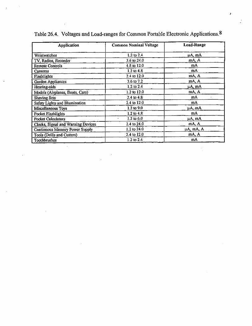
Table 26.4. Voltages and Load-ranges for Common Portable Electronic Applications.*
I Application Common Nominal Voltage Load-Range

TABLE 26.5. Candidate Battery Systems for EV, UES, and RES Applications.
i
Chapter and section reference
This info needs to be supplied Commercially available batteries
Lead-acid Nickel-iron by David Linden. Nickel- hydrogen Nickel/cadmium Zinc/silver oxide
Nickel/metal hydride (2) Nickel-zinc (2) Zinc/chlorine (1) Zinc/bromine (2) Redox systems (1) Metal/air
Iron/air ( I ) Zinc/air (2) Lithiurn/air (1) Aluminum/air (2)
Hydrogen/halogen (1) High- temperature batteries
Lithium/chlorine (1) Lithium/tellurium chloride ( 1 ) Lithium/sulfur (1) Lithium-aluminum/iron sulfide (2) Lithium-aluminum/iron disulfide (3) Calcium/iron sulfide (1) Sodium/sulfur (2) Sodium/metal chloride (2) Sodium/antimony trichloride (1)
Lithium ambient- temperature batteries Liquid electrolyte (3) Solid electrolyte (3)
Aqueous batteries
NOTES: 1. No known activities in progress at this time. 2. Mid-term technology. 3. Long-term technology.
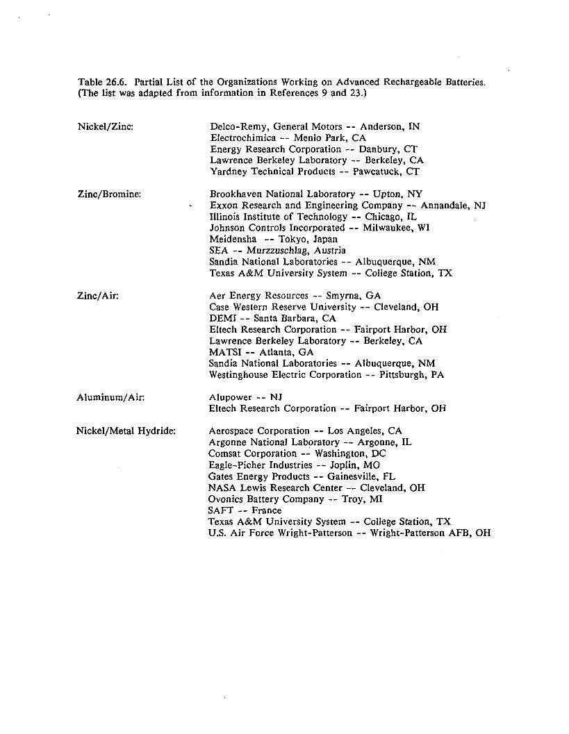
Table 26.6. Partial List of the Organizations Working on Advanced Rechargeable Batteries. (The list was adapted from information in References 9 and 23.)
Nickel/Zinc:
Zinc/Bromine:
Zinc/Air:
Delco-Remy, General Motors -- Anderson, IN Electrochimica -- Menlo Park, CA Energy Research Corporation -- Danbury, CT Lawrence Berkeley Laboratory -- Berkeley, CA Yardney Technical Products -- Pawcatuck, CT
Brookhaven National Laboratory -- Upton, NY Exxon Research and Engineering Company -- Annandale, NJ Illinois Institute of Technology -- Chicago, IL Johnson Controls Incorporated -- Milwaukee, WI Meidensha -- Tokyo, Japan SEA -- Murzzuschlag, Austria Sandia National Laboratories -- Albuquerque, NM Texas A&M University System -- College Station, TX
+
Aer Energy Resources -- Smyrna, GA Case Western Reserve University -- Cleveland, OH DEMI -- Santa Barbara, CA Eltech Research Corporation -- Fairport Harbor, OH Lawrence Berkeley Laboratory -- Berkeley, CA MATS1 -- Atlanta, GA Sandia National Laboratories -- Albuquerque, NM Westinghouse Electric Corporation -- Pittsburgh, PA
Aluminum/Air: Alupower -- NJ Eltech Research Corporation -- Fairport Harbor, OH
Nickel/Metal Hydride: Aerospace Corporation -- Los Angeles, CA Argonne National Laboratory -- Argonne, IL Comsat Corporation -- Washington, DC Eagle-Picher Industries -- Joplin, MO Gates Energy Products -- Gainesville, FL NASA Lewis Research Center -- Cleveland, OH Ovonics Battery Company -- Troy, MI SAFT -- France Texas A&M University System -- College Station, TX U.S. Air Force Wright-Patterson -- Wright-Patterson AFB, OH

Sodium/Sulfur: ABB Advanced Battery Systems -- Mississagua, Ontario, Canada Ceramatec, Incorporated -- Salt Lake City, UT Eagle-Picher Industries -- Torrance, CA Hitachi -- Japan Hughes Aircraft Company -- Los Angeles, CA Nastech -- Japan Sandia National Laboratories -- Albuquerque, NM Silent Power, Incorporated -- Salt Lake City, UT Silent Power Limited -- Runcorn, UK-England U.S. Air Force Phillips Laboratory -- Albuquerque, NM Yuasa -- Japan
Sodium/Metal Chloride: AEG Anglo Battery Holdings -- Germany Argonne National Laboratory -- Argonne, IL Jet Propulsion Laboratory -- Pasadena, CA
Lithium/Iron Sulfide Lithium/Iron Disulfide: Argonne National Laboratory -- Argonne, IL
British Aerospace Royal Establishment -- United Kingdom Eagle-Picher Industries -- Joplin, MO Electrofuel --Toronto, Ontario, Canada SAFT-America -- Cokeysville, MD Vickers -- United Kingdom Westinghouse Electric Corporation -- Chardon, OH
Lithium/Organic Liquid
Lithium/Solid Polymer Electrolyte:
Electrolyte: A. D. Little -- Cambridge, MA A/S -- Denmark AT & T Bell Labs -- Morristown, NJ Alcatel -- Switzerland Alliant Techsystems, Inc. -- Horsham, PA Allied-Signal Incorporated -- Morristown, NJ Arizona State University -- Tempe, AZ Battery Engineering Incorporated -- Hyde Park, MA Bellcore -- Red Bank, NJ Brookhaven National Laboratory -- Upton, NY Covalent Associates -- Woburn, MA Duracell, Inc. -- Bethel, CT EIC Laboratories, Inc. -- Norwood, MA Energy Research Laboratories -- Denmark Eveready -- Westlake, OH Gould, Inc. -- Rolling Meadow, IL Harwell Laboratory -- United Kingdom Hitachi-Maxwell -- Japan Hope Technologies Incorporated -- Willow Grove, PA Hydro-Quebec -- Canada Jet Propulsion Laboratories -- Pasadena, CA Lawrence Berkeley Laboratory -- Berkeley, CA Lawrence Livermore National Laboratory -- Livermore, CA Matsushita -- Japan

Moli Energy Limited -- Canada NEC -- Japan SAFT America, Inc. - Cokeysville, MD SRI International - Palo Alto, CA Sandia National Laboratories -- Albuquerque, NM Sanyo -- Japan Sharp Kabushika -- Japan Simon Fraser University -- Canada Sony Energetic Incorporated -- Japan Toshiba Battery Company -- Japan University of Minnesota -- Minneapolis, MN University of Rome -- Italy Valence Technologies -- San Jose, CA W. R. Grace & Company -- Columbia, MD Wilson Greatbatch, Ltd. -- Clarance, NY Wright Laboratory -- Wright-Patterson AFB, OH Yuasa Battery Company -- Japan

Unless otherwise
Technology LeadAcid-VRL A
NickeUCadmium
Nickemon
NickelBydrogen
Zinc/SiIver Oxide
NickeUZinc
ZincBromine
Zinc/Air
NickeVMetal Hvdride sodium/sulfur
Sodium/Nickel Chloride5 Lithium/Iron Monosulfide Lithium /iron Disulfide
Electrolyte Lithium/PoIymer
noted, numerical data are tiom Reference 9. Specific Open Closed Theoretical Theoretical Configuration Specific Energy
Circuit Circuit Capacity2 Specific Energy1 Density Power4 Voltage Voltage1 m g E n e d w a g WM W k V V Whkg
2.15 1.98 83 170 cell 30 (50) 85 (100) 200-130 Battery 25 60 (400)
1.35 1.20 179 218 Cell 40 (55) 70 (75) 260 (300)
1.35 1.20 2 14 267 Cell 53 (60) 120 (130) 100 (1 10)
1.35 1.20 289 365 cell 50 (70) 80 (100) 100 (150)
1.86 1.55 259 490 Cell 140-180 (160-200) 400-500 (500-600) 500 (500) Battery 100- 160 200-450
1.80 1.60 188 34 1 cell 70 (75) 140 (150) 300 (320)
1.80 1.60 238 440 Battery 70 (80) 56 (100) 60 (100)
1.4 1.1 253 500 Cell 110 120 (95)
1.35 1.20 196 265 Cell 60 (65) 120 (120) 100 (150)
2.076 2.01 377 760 Cell 175 (250) 350 (420) 250 (400) Battery 80-100 (175) 110-130 (265) 150
2.58 2.41 305 790 Battery 100 (130) 115 (170)
1.47 1.30 345 457 Cell 100 250 180 Battery 85 175 140
1.80 1.68 418 630 Cell 175 350 600
-- 2.4-3.4 -- -I
110 (170)
Battery 1 506 2006 1606

Table 26.7 Continued. Comparative Data for Rechargeable Battery Technologies. Values in parentheses are projections to the year 2000. Unless otherwise
Technology LeadAcid-VRLA
NickeVCadmim
NickeVIron
NickeUHydrogen
ZindSilver Oxide
NickelEinc
ZincdBromine
ZindAir
NickeVMetal Hydride Sodium/Sulfur
SodiumNickel Chloride LithiumlIron Monosulfide Lithium /Iron Disulfide LithiunVPolymer Electrolyte
noted, numerical data are fiom Reference 9. Self Discharge Cycle Operating Recharge cost Applications AdvantagedDisadvantages % per month Life' Temperature Time 1992 $
20oc "C hrs per kwh 800 (1200) -18 to 50 8-24 (24) 2 0 (150) Electric Vehicles Utility C o d a l l y adab le , No
Energv Storage, collsumer maintenanoelLow specific energy
commacially availablelLow sp.Citic eaergy, High oost
maintenance, Significant H2 evolution
discharge
cost. Very short life
life
3 (2) (-25 to 60)
1-16 2000 (2000) Electricvehicles Aer~ce,consumer
15 (10) 2000 -40 to 60 (3000)
(1200) 25 (10) 1000 -10 to 60 5 500 (200) Electric Vehicles Commercially available/ High
60 (25) 2000 -10 to 30 1-24 50,000 AemsPace, Military Long IifeNery high cost, High self-
(3000) (25,000) 475-2500 Aerospace, Military, High specific energy and powerEIigh
5000 (300) Electric Vehicles High specific enagyfl3igh cost, Short
5 (2) 40-50 -20 to 60 8 3 8 (50-70) (475-2000) consumer
15 (10) 200 (500) -20 to 50 8
_- (low) E l e d c Vehicles, Utility Low oost/low specific power and Energy Storage e n ~ density
Electric Vehicles
(35) 300 (1000) 25 to 50
Moderate specific energy/Shott life, Low specific power
High specific powerrnigh mst, Short l i e
0 to 45 -- I - (600)
1-24 3500 (2500) E l d c V A C k 350 (1000) -10 to 40 A e r ~ c O n s U m e r
Ell~stora~Aerospace d e n s i t y r n g h ~ t u r e
50 (30)
0 600 (1000) 3 10 to 350 5-6 2000 (150) E l d c Vehicles, Utility High specific and e n w
3-6 I Eledric Vehicles Highspecificenergy/Hi&temperature 0 1000 250 to 350
0 1000 375 to 500 5-8 - Eledric Vehicles High energy densityhw specific
0 1000 375 to 450 5-8 -- Eledric Vehicles High specific energy and poweriHigh
I 1000 25 to 100 - - Electric Vehicles, Consumer All d i d state, High specific
Pow, higtttemperature
temperature
energy/Significant development needed estimated
.

1. At CY5 rate.
2. Calculated values based on the electrochemical cell reactions.
3. Values for leadacid and zinc/air are from the Dictionary of Electrochemistry, 2nd Ed., D. B. Hibbert and A. M. James, eds. Wiley Interscience, 1984. Values for nickellcadmiurn, nickeviron, zinc/siIver, and nickellzinc are from UlImann's Encyclopedia of Industrial Chemistry, 5th Ed., W. Gerhartz, ed., VCH Publishers, Vol A3, "Batteries." The value for nickelhydrogen is from *'Low Earth Orbit Nickel-Hydrogen Cell Technology and Development Plan," August 1981, Lewis Research Center, National Aeronautics and Space Administration. The value for nickellmetal hydride is courtesy of Narayan Doddapaneni, Sandia National Laboratories. The value for zinchromine is calculated based on Eocell=1.85 V. Values for sodiumlsulfur, lithiudiron monosulfide, and lithiumhron disulfide are from R K. Sen, "Assessment of High-Temperature Battery Systems," February 1989, Battelle, PNL-SA-16675. The value for sodiurdnickel chloride is from C. Dustmann and J. L. Sudworth, "ZEBRA Powers Electric Vehicles," 1 1 th International Electric Vehicle Symposium, Florenz, Italy, September 27-30, 1992.
1. Short duration pulse, fully charged to half-charged except sodium/sulfur, lithiundiron monosulfide, and lithium/iron disulfide which are 80% to 50% charged. The values listed do not reflect the maximum that is achievable if specifically designed for power density,
5 . Data for sodidnickel chloride is based on "Sodium Beta Batteries" by J. W. Braithwaite and W. L. Auxer, Chapter XX, this handbook.
6. Based on a Sandia National Laboratories conceptual design for a bipolar lithium-ion battery using limited cell performance data.
7. At C/5 rate down to 80% rated capacity.