chapter 2.0 selecting, designing, constructing and
TRANSCRIPT

Stormwater Management Manual 2-1 Eugene 2014
Chapter 2.0
SELECTING, DESIGNING, CONSTRUCTING AND LANDSCAPING STORMWATER MANAGEMENT FACILITIES
This chapter provides procedures for selecting and designing stormwater facilities that provide stormwater flood control, quality, and flow control. It includes: 2.1 INTRODUCTION ...................................................................................................................................... 3 2.2 STORMWATER FACILITIES ............................................................................................................... 3
2.2.1 Impervious Area Reduction Techniques .............................................................. 3 2.2.2 Infiltration Treatment Facilities .............................................................................. 3 2.2.3 Filtration Treatment Facilities .................................................................................. 3 2.2.4 Mechanical Treatment Devices ................................................................................ 3 2.2.5 Facility Underdrains and Surface Overflows ...................................................... 4 2.2.6 Source Control Devices ................................................................................................ 4
2.3 FACILITY DESIGN CRITERA ............................................................................................................... 5 2.3.1 Public Stormwater Facilities ..................................................................................... 7 2.3.2 Private Stormwater Facilities ................................................................................... 7 2.3.3 Contained Planter .......................................................................................................... 9 2.3.4 Eco-Roof ......................................................................................................................... 11 2.3.5 Permeable Pavements .............................................................................................. 15 2.3.6 Trees ................................................................................................................................ 17 2.3.7 Filter Strip ...................................................................................................................... 19 2.3.8 Ponds ............................................................................................................................... 21 2.3.8.1 Wet Ponds ...................................................................................................................... 21 2.3.8.2 Extended Wet Ponds ................................................................................................. 21 2.3.8.3 Dry Detention Ponds ................................................................................................. 21 2.3.9 Rain Garden................................................................................................................... 25 2.3.10 Sand Filter ...................................................................................................................... 29 2.3.11 Stormwater Planter ................................................................................................... 31 2.3.12 Swale ................................................................................................................................ 35 2.3.13 Proprietary Treatment Devices............................................................................. 39 2.3.14 Spill Control Manhole ................................................................................................ 41 2.3.15 Structural Detention Facility .................................................................................. 43 2.3.16 Drywell ............................................................................................................................ 45 2.3.17 Soakage Trench ........................................................................................................... 47
2.4 FACILITY SIZING APPROACHES ................................................................................................... 49 2.4.1 Simplified Approach (SIM Form 2013) .............................................................. 49 2.4.2 Presumptive Approach ............................................................................................. 50
2.5 HYDROLOGIC ANALYSIS .................................................................................................................. 52 2.6 ACCESS FOR OPERATIONS AND MAINTENANCE ................................................................. 54 2.7 OUTFALL DESIGN ................................................................................................................................ 55 2.8 CONSTRUCTION CRITERIA ............................................................................................................. 56

Stormwater Management Manual 2-2 Eugene 2014
2.8.1 Public Stormwater Facilities .................................................................................. 56 2.8.2 Site Preparation and Grading ................................................................................. 56 2.8.3 Erosion and Sedimentation Plans ........................................................................ 56 2.8.4 Piping ............................................................................................................................... 56 2.8.5 Gravel Drain Rock ....................................................................................................... 57 2.8.6 Geotextiles ..................................................................................................................... 57
2.9 LANDSCAPE REQUIREMENTS ........................................................................................................ 58 2.9.1 Relationship to Other Landscape Requirements ............................................ 58 2.9.2 Public Easement and Rights of Way Vegetation ............................................. 58 2.9.3 Growing Medium ........................................................................................................ 58 2.9.4 Vegetation ...................................................................................................................... 59 2.9.5 Vegetation Coverage .................................................................................................. 60 2.9.6 Grass Coverage ............................................................................................................ 60 2.9.7 Mulch ............................................................................................................................... 60 2.9.8 Irrigation ........................................................................................................................ 60 2.9.9 Preventing Pollutants ................................................................................................ 60

Stormwater Management Manual 2-3 Eugene 2014
2.1 INTRODUCTION Stormwater facilities presented in this chapter satisfy the standards established for stormwater quality, flow control, flood control, and in some cases a combination of the three. Two sizing methodologies are included in this chapter: the simplified and presumptive approaches. Each sizing approach has limitations on application, particularly as related to the soil types on-site. Soil formations are classified by NRCS soil types A, B, C, or D. For the purposes of this manual, NRCS soild types A & B are presumed to have infiltration rates of 2” per hour and greater. NRCS soils tptes C & D are assumed to have infiltration rates less than 2” per hour. 2.2 STORMWATER FACILITIES This section identifies techniques to reduce impervious surface treatment areas and the three classifications of stormwater quality facilities. 2.2.1 Impervious Area Reduction Techniques Contained Planters, Eco roofs, Permeable Pavements, and Tree Credits are impervious area reduction techniques. These techniques reduce the effective area of imperious surface and reduce the size of the resulting stormwater quality facility. Impervious area reduction techniques reduce runoff pollution and mitigate the volume, duration, time of concentration and rate of runoff. Eco roofs, permeable pavements, and trees intercept rainfall directly and are not allowed to receive stormwater runoff from other impervious surface areas. Contained Planters may either intercept the rainfall or receive stormwater runoff from impervious surfaces areas if sized using the Presumptive Approach. All impervious area reduction techniques may be used for private facilities. Impervious area reduction shall not be used for public facilities. 2.2.2 Infiltration Treatment Facilities Infiltration treatment facilities require soils that drain well and infiltrate 2 inches per hour or greater. Infiltration treatment facilities require an overflow to an approved point of discharge unless they are sized to fully infiltrate the Flood Control Design Storm event. When sized for flood control, infiltration treatment facilities must infiltrate the Flood Control Design Strom Event within 30 hours. 2.2.3 Filtration Treatment Facilities Filtration treatment facilities are appropriate for sites with soils that infiltrate less than 2 inches per hour, have bedrock less than 5 feet below the surface, groundwater elevations less than 6 feet or slopes greater than 10%. They include a surface overflow and an underdrain in the gravel layer where treated flow is routed to an approved discharge point. Lined filtration treatment facilities may be approved on sites with steep slopes, high groundwater, or contamination and when located next to structures or property lines to protect foundations, basements, and adjacent properties. Otherwise the use of liners is discouraged to maximize what infiltration is availible from native soils. 2.2.4 Mechanical Treatment Devices Manufactured treatment devices must be selected from the list of approved proprietary treatment technologies and sized using the Presumptive Approach. Proprietary treatment

Stormwater Management Manual 2-4 Eugene 2014
technologies that are not on the approved list may be used in a “treatment train,” to provide additional treatment when approved by the City. Manufactured treatment devices must be able to fully treat the peak runoff from the Water Quality Design Storm and fully bypass the peak flows from the Flood Control Design Storm. 2.2.5 Facility Underdrains and Surface Overflows It is important to note the distinction between an underdrain and a surface overflow. While both the underdrain and the overflow require a connection to an approved discharge point, the underdrain is typically set at an elevation below the growing medium to drain treated flows that pass through the growing medium and are trapped in a facility where the surrounding soils infiltrate 2” per hour or less. An overflow is typically set at an elevation above the growing medium and is included to drain flows exceeding the stormwater quality design capacity of the facility or in case the vegetated facility becomes clogged. 2.2.6 Source Control Devices Source control devices include Spill Control Manholes and oil/water separators. They are used to meet the source control requirements specified in Chapter 3.

Stormwater Management Manual 2-5 Eugene 2014
2.3 FACILITY DESIGN CRITERA This section provides a description and the specific design requirements for each stormwater facility listed below. Typical design drawings are provided in Appendix B. Variations that exist between the Simplified Approach and Presumptive Approach and variations between public and private facilities are identified. Table 2-1 identifies the approved sizing methods for each facility type as well as the conformance with stormwater management standards given for each facility type.

Stormwater Management Manual 2-6 Eugene 2014
Table 2-1 Sizing methods and conformance with stormwater management standards for each facility type
Facility Sizing Approaches Stormwater Management Standard
Simplified Presumptive Water Quality
Flow Control
Flood Control
Impervious Area Reduction Techniques 2.3.3 Contained Planter X X 2.3.4 Eco roof X X 2.3.5 Permeable
Pavement X X
2.3.6 Tree Credit X X Infiltration Treatment Facilities 2.3.8 Pond X X X X 2.3.9 Rain Garden X X X X X 2.3.10 Sand Filter X X X X X 2.3.11 Stormwater
Planter X X X X X
Filtration Treatment Facilities 2.3.7 Filter Strip X X X 2.3.8 Pond X X X X 2.3.9 Rain Garden X X X X X 2.3.10 Sand Filter X X X X X 2.3.11 Stormwater
Planter X X X X X
2.3.12 Swale X X X X X Mechanical Treatment Facilities 2.3.13 Proprietary
Treatment Devices
X X
Source Control Devices 2.3.14 Spill Control
Manhole X X
Detention Facilities 2.3.15 Structural
Detention Facility X X
Underground Injection Systems 2.3.16 Drywell X X 2.3.17 Soakage Trench X X
Notes: Flow Control and Flood Control Credit are given when facilities are sized to accommodate design events per the simplified and presumptive methods.

Stormwater Management Manual 2-7 Eugene 2014
2.3.1 Public Stormwater Facilities The City will operate and maintain only certain types of stormwater facilities. Stormwater facilities that can be located in dedicated public rights of way and public easements are: Filter Strips, Ponds, Rain Gardens, Stormwater Planters, Swales, Proprietary Treatment Devices, Spill Control Manholes, and Structural Detention Facilities. In addition to the stormwater quality sizing and design requirements set forth in this manual, public facilities must be designed in compliance with the Public Improvement Design Standards (PIDS) Manual and Eugene adopted Oregon Standard Specifications for Construction. 2.3.2 Private Stormwater Facilities In addition to the stormwater quality sizing and design requirements set forth in this manual, private stormwater facilities must be designed in compliance with the Uniform Building and Uniform Plumbing Codes.

Stormwater Management Manual 2-8 Eugene 2014
This Page Intentionally Left Blank

Stormwater Management Manual 2-9 Eugene 2014
2.3.3 Contained Planter Facility Description Contained Planters are free-standing plant containers placed over impervious surfaces such as patios, sidewalks, and rooftops that intercept and filter rainfall that would otherwise contribute to stormwater runoff from the underlying impervious surface. Contained planters may be prefabricated pots of various dimensions or may be constructed in place and have an infinite variety of shapes and sizes. Contained Planters intercept precipitation only when sized under the Simplified Approach, not stormwater runoff from other impervious areas. Runoff from other impervious areas is allowed when sized under the Presumptive Approach. Drainage is allowed through the bottom of the planter onto the impervious surface. Contained Planters meet the stormwater management standard for imperious area reduction techniques. Design Requirements Sizing: Contained Planters replace impervious area at a 1:1 ratio. Soil Suitability: Contained Planters are appropriate for all soil types, as they are typically placed over impervious surface. The growing medium shall be a minimum 12 inches of topsoil. Setbacks: Not applicable. Materials Planter Walls: Planter walls shall be made of stone, concrete, brick, clay, plastic, wood, or other stable material. Chemically treated wood that can leach out toxic chemicals and contaminate stormwater shall not be used. Vegetation Contained Planters shall be planted to cover at least 50% of the planter surface. Plants shall be relatively self-sustaining, with little need for fertilizers or pesticides. Irrigation is optional, although plant viability must be maintained. Planters tend to dry out more quickly due to reflective heat. Insulation to protect roots may be necessary. Trees are encouraged and may qualify for additional impervious area reductions.

Stormwater Management Manual 2-10 Eugene 2014
This Page Intentionally Left Blank

Stormwater Management Manual 2-11 Eugene 2014
2.3.4 Eco-Roof Facility Description Eco-Roofs are impervious area reduction techniques. Eco-Roofs are vegetated roof systems used in place of conventional roofs. Eco-roofs provide stormwater management by capturing, filtering, and, depending on the season, evapo-transpirates precipitation while providing aesthetic and energy conservation benefits. Eco-Roofs meet the stormwater management standard for imperious area reduction techniques. Design Requirements Sizing: Eco-Roofs replace impervious area at a 1:1 ratio. They are not allowed to receive water from other impervious areas. Slope: Maximum roof slope shall be 25% unless the applicant can provide documentation for runoff control on steeper slopes. Drain: As with a conventional roof, an Eco-Roof must safely drain runoff from the roof to an approved stormwater destination. Materials Structural Roof Support: The structural roof support must be sufficient to hold the additional weight of the Eco-Roof. For retrofit projects, check with an architect, structural engineer, or roof consultant to determine the condition of the existing building structure and what might be needed to support an Eco-Roof. This might include additional decking, roof trusses, joists, columns, and/or foundations. Generally, the building structure must be adequate to hold an additional 10 to 25 pounds per square-foot (psf) saturated weight, depending on the vegetation and growth medium that will be used. (This is in addition to snow load requirements.) An existing rock ballast roof may be structurally sufficient to hold a 10-12 psf Eco-Roof. (Ballast typically weighs 10-12 psf.) For New Construction: The project architects and structural engineers shall address the structural requirements of the Eco-Roof during the design process. Greater flexibility and options are available for new buildings than for re-roofing. The procedures for the remaining components are the same for both re-roofing and new construction. Waterproof Membrane (Impermeable Material): Good quality waterproofing material must be used on the roof surface. Waterproof membranes are made of various materials, such as modified asphalts (bitumens), synthetic rubber (EPDM), hypolan (CPSE), and reinforced PVC. Some of the materials come in sheets or rolls and some are in liquid form. They have

Stormwater Management Manual 2-12 Eugene 2014
different strengths and functional characteristics. Some of these products require root inhibitors and other materials to protect the membrane. Numerous companies manufacture waterproofing materials appropriate for Eco-Roofs. Protection Boards or Materials: These materials protect the waterproof membrane from damage during construction and over the life of the system, usually made of soft fibrous materials. Root Barrier (if needed): Root barriers are made of dense materials that inhibit root penetration. The need for a root barrier depends on the waterproof membrane selected. Modified asphalts usually require a root barrier, while synthetic rubber (EPDM) and reinforced PVC generally do not. Check with the manufacturer to determine if a root barrier is required for a particular product. Membranes impregnated with pesticides are not allowed. Manufacturers shall disclose the concentration of leach out for membranes impregnated with copper. Drainage Layer (if needed): There are numerous ways to provide drainage. Products range from manufactured perforated plastic sheets to a thin layer of gravel. Some Eco-Roof designs do not require any drainage layer other than the growth medium itself, depending on roof slope and size (for example, pitched roofs and small flat roofs). Gravel Ballast (if needed): Gravel ballast is sometimes placed along the perimeter of the roof and at air vents or other vertical elements. The need for ballast depends on operational and structural design issues. It is sometimes used to provide maintenance access, especially to vertical elements requiring periodic maintenance. In many cases, very little, if any, ballast is needed. In some situations a header or separation board may be placed between the gravel ballast and adjacent elements (such as soil or drains). If a root barrier is used, it must extend under the gravel ballast and growth medium, and up the side of the vertical elements. Vegetation Eco-Roof vegetation should have the following attributes:
• Drought-tolerant, requiring little or no irrigation after establishment • Growth patterns that allow the plants to thoroughly cover the soil (at least 90% of
the overall surface should be covered and maintained within 2 growing seasons) • Self-sustaining, without the need for fertilizers, pesticides, or herbicides able to
withstand heat, cold, and high winds • Very low-maintenance, needing little or no mowing or trimming • Perennial or self-sowing • Fire resistant
A mix of sedum/succulent plant communities is recommended because they possess many of these attributes. Herbs, forbs, grasses, and other low groundcovers can also be used to provide additional benefits and aesthetics; however, these plants may need more watering and maintenance to survive and keep their appearance.

Stormwater Management Manual 2-13 Eugene 2014
Four methods (or combinations of them) are generally used to install the vegetation: vegetation mats, plugs/ potted plants, sprigs, and seeds.
1. Vegetation mats are sod-like, pre-germinated mats that achieve immediate full plant coverage. They provide immediate erosion control, do not need mulch, and minimize weed intrusion. They also need minimal maintenance during the establishment period and little ongoing watering and weeding. Plugs or potted plants may provide more design flexibility than mats. However, they take longer to achieve full coverage, are more prone to erosion, need more watering during establishment, require mulching and more weeding.
2. Sprigs are hand-broadcast. They require more weeding, erosion control, and watering than mats.
3. Seeds can be either hand-broadcast or hydraseeded. Like sprigs, they require more weeding, erosion control, and watering than mats.
4. Soil coverage to prevent erosion shall be established immediately upon
installation by using mulch, vegetation mats, or other approved protection method. Ninety-percent (90%) plant coverage should be achieved within 2 years. Temporary irrigation to establish plants is recommended. A permanent irrigation system using potable water may be used, but an alternative means of irrigation, such as air conditioning condensate or other non-potable sources, is recommended. Alternative sources should be analyzed to determine if the source has chemicals that might harm or kill the vegetation.
Growth Medium (Soil): The growth medium is generally 2 to 6-inches thick and well drained. It weighs from 10 to 25 pounds per square-foot when saturated. A simple mix of one-fourth topsoil, one-fourth compost, and one-half pumice perlite may be sufficient for most applications. Some companies have their own growth medium specifications. Other components may include digested fiber, expanded clay or shale, or coir.

Stormwater Management Manual 2-14 Eugene 2014
This Page Intentionally Left Blank

Stormwater Management Manual 2-15 Eugene 2014
2.3.5 Permeable Pavements Facility Description Permeable Pavements are impervious area reduction techniques. Permeable Pavements are pervious and porous load bearing structures with an underlying stone reservoir that temporarily stores and filters surface runoff before infiltrating into the subsoil or being collected in underlying drain pipes and being discharged off-site. Permeable pavements include, but are not limited to, pervious concrete, asphalt, plastic/concrete rings planted with grass, stone and block pavers. The system generally consists of a permeable wearing course surface placed upon layered permeable base materials. Permeable pavements can be used in pedestrian areas, patios, plazas, parking lots, driveways and other traditionally hardscaped areas. Numerous products and design approaches are available, including special asphalt paving; manufactured concrete, plastic, and gravel products; paving stones; and brick. Permeable pavements must be installed and maintained to manufacturer’s specifications. Permeable pavement systems that will be supporting vehicular traffic should be designed to accommodate traffic loading. Permeable Pavements meet the stormwater management standard for imperious area reduction techniques. Design Requirements Sizing: Permeable pavements replace impervious area at a 1:1 ratio. They are not allowed to receive runoff from other impervious areas. Runoff from the flood control event shall be accommodated through an approved point of discharge. Dimensions and Slopes: Minimum/maximum dimensions and other specifications are product-specific and shall comply with the design or manufacturer’s specifications. Slopes exceeding 5% shall demonstrate the ability to retain stored runoff. Slopes shall be less than 10% in all cases. Setbacks: There are no required setbacks for pervious paver systems. Subgrade: Permeable pavement should not be constructed over highly compacted soils. Compaction should be kept to minimum as not to decrease the permeability of native or import soils. Limitations: Permeable Pavements shall not be used on sites with a likelihood of high oil and grease concentrations. These site uses include vehicle wrecking or impound yards, fast food establishments, automotive repair and sales. Settlement can be expected due to the uniform gradation of materials.

Stormwater Management Manual 2-16 Eugene 2014
Materials Geotextile Fabric: Subgrade geotextile for separation is required between subgrade (native soil) and aggregate base (gravel layer). Geotextile may also be required between the sand layer and the aggregate base as required by the product manufacturer. Aggregate Base: A permeable layer of open graded base rock shall be provided for storage of runoff and the structural platform for the wearing surface. The aggregate base layer shall be designed to accommodate the specific volume of rainfall storage required and the anticipated surface design loads. In no case shall the layer be less than 6 inches. Diameter of aggregate base shall be no greater than 2-1/2 inch and no less than 3/4-inch. Bedding Course: A layer of sand or small diameter aggregate shall be provided for permeable pavers as recommended by the manufacturer. The bedding course shall be no less than 1-inch thick. Paving Courses: Paving courses shall be designed for the anticipated surface loads and the aggregate base layer design. All paving courses shall be permeable as to infiltrate stormwater directly into the aggregate storage layer. Asphalt mixes shall be of the open graded design. Permeable concrete mixes shall be of the open graded design with little or no sand. Permeable pavers and other premanufactured products should be installed per manufactures recommendations.

Stormwater Management Manual 2-17 Eugene 2014
2.3.6 Trees Facility Description Trees intercept precipitation and hold water on the leaves and branches and allow it to evaporate, Trees retain runoff and dissipate the energy of runoff. They also provide shade, providing two direct benefits. First, hard surfaces are protected from direct solar exposure, which reduces heat gain. The less heat gain there is in pavement, the less heat is absorbed by stormwater as it flows over the surface. Second, by shading pavement, the trees help reduce or minimize air temperature increases caused by the hot pavement. Cooler air may help prevent stream temperature increases associated with air temperatures. These functions are most measurable for storms of less than 0.5 inches over 24 hours. While deciduous trees are not as effective during winter months, evergreen trees are effective year round for these smaller storms and portions of larger storms. Generally, large trees with small leaves are the most efficient rainfall interceptors. Trees also facilitate stormwater infiltration and groundwater recharge. Trees meet the stormwater management standard for imperious area reduction techniques. Design Requirements New Evergreen and Deciduous Trees: New large trees planted within 25 feet of ground-level impervious surfaces, and new small trees, or slowly growing larger trees, planted within 10 feet, are eligible for impervious area reduction. Trees may be applied to ground-level surfaces only; roofs may not reduce impervious area. A reduction of 100 square feet is given for new deciduous trees, and 200 square feet of reduction is given for new evergreen trees (see minimum sizes below). Impervious area reductions also apply to existing trees kept on a site if the trees’ canopies are within 25 feet of ground-level impervious surfaces. The reduction is the square-footage equal to one-half of the existing tree canopy within the 25 foot area. No more than 10% of a site’s impervious surface can be mitigated through the use of trees. Trees used for impervious area reduction shall be clearly labeled on permit drawings. Trees shall be maintained and protected on the site after construction and for the life of the development (50-100 years or until any approved redevelopment occurs in the future). During the life of the development, trees approved for impervious area reduction shall not be removed without approval from the City. Trees that are removed or die shall be replaced within 6 months with like species. All trees should be pruned to ANSI standards.

Stormwater Management Manual 2-18 Eugene 2014
The trees selected shall be suitable species for the site conditions and the design intent. Trees should be relatively self-sustaining and long-lived. Temporary irrigation should be provided for native plantings. Long-term irrigation is optional. New deciduous trees shall be at least 2 caliper inches and new evergreen trees must be at least 6 feet tall to receive Simplified Approach credit. Trees planted to meet stormwater management facility planting requirements, except those located in Contained Planters, may not also receive Impervious Area Reduction Technique credits on the SIM Form. Trees used to meet stormwater management requirements shall be kept on a site and maintained properly to ensure continued stormwater benefits. Trees should be inspected 2 times a year and within 48 hours of a major wind or storm event. Existing Trees: Impervious area reduction applies to existing trees of 4-inch caliper or larger. Large trees which reduce impervious area must be located within 25’ of proposed or existing ground-level impervious surfaces; small trees must be located within 10’ of proposed or existing ground level impervious surfaces. Impervious area reduction is based on one-half of the square footage of the tree canopy, measured within the drip-line. Protection during construction shall be in conformance with the City’s tree preservation standards. The applicant will have to provide documentation required by the City to ensure the tree will remain healthy after construction and during the life of the project. During the life of the development, trees approved for stormwater credit shall not be removed without approval from the City. Stormwater management functions of any removed trees shall be replaced on the site with other trees or stormwater management approaches. Trees that die shall be replaced within 6 months.

Stormwater Management Manual 2-19 Eugene 2014
2.3.7 Filter Strip Facility Description Filter Strips are gently sloped vegetated or grassed areas that stormwater runoff is directed to flow over and filter through. Stormwater enters the filter as sheet flow from an impervious surface or is converted to sheet flow using a level spreader. Pollutants are removed through filtration and sedimentation. There are an infinite number of ways to fit this concept into site designs and designers are encouraged to use the site landscape areas for this purpose. Filter Strips can be used to treat hydraulically isolated or irregularly shaped impervious areas such as driveways, walkways and patio areas. A filter strip may be used in hydraulically isolated areas where it can be demonstrated that no natural or formal stormwater conveyance system exists. Runoff patterns must conform to Oregon Drainage Law . Filter Strips qualify as filtration facilities and meet the stormwater management standard for water quality. Design Requirements Sizing: The Simplified Approach shall be used to size Filter Strips receiving less than 1000 sf of impervious area or sheet flow runoff from continuous linear impervious areas of consistent cross section on a unit basis. Examples are driveways, patios, sidewalks, bike baths and narrow access roads less than 20 feet wide. Filter Strips shall use a sizing factor of 0.2 for water quality with the Simplified Method. Soil Suitability: Filter Strips are appropriate for all soil types. Unless existing vegetated areas are approved as a filter, stormwater facility growing medium shall be used for the top 12 inches of the facility or the soil shall be amended to support plant growth. Setbacks: The facility must begin 5 feet from the property line; 10 feet from buildings; and 50 feet from wetlands, rivers, streams, and creeks, unless otherwise approved by the City of Eugene. Dimensions and Slopes: Filter Strips shall slope between 0.5 and 10 percent. Terraces may be used to decrease ground slopes. Slopes shall not exceed 5% for grassed facilities. Filter strip shall have a minimum width of 5 feet measured in the direction of flow.

Stormwater Management Manual 2-20 Eugene 2014
Level Spreaders: A grade board, perforated pipe, or trench may be required to disperse the runoff evenly across the Filter Strip. The top of the level spreader must be horizontal and at an appropriate height to provide sheet flow directly to the soil without scour. Grade boards can be made of any material that will withstand weather and solar degradation. Trenches used as level spreaders can be filled with washed crushed rock, pea gravel, or sand. Exposed pipe should be protected from weather and solar degradation . Materials Check Dams: Check dams shall be installed every 10’ of facility measured in the direction of flow. Check dams shall be constructed of durable, non-toxic materials such as rock or brick or graded into the native soils. Check dams shall be 12 inches wide, 3 to 5 inches high, and run the length of the filter. Vegetation The Filter Strip must maintain 90 percent coverage by vegetation or 100 percent coverage by grass at establishment. Vegetation shall conform to the facility planting list located in Appendix D. Vegetated filter strips shall be planted with minimum plant quantities from Schemes I, II or III. Minimum plant quantities are as follows:
Vegetated Filter Strip Planting Scheme I II III Ground Cover, 4-inch pots spaced 1’ on center (per 100 square feet of the facility)
100 80 60
Small Shrubs, 1 gal. pots spaced 2’ on center (per 100 square feet of the facility)
4 12
Grassy filter Strips must have 100 percent coverage by native grasses, turf grasses, native wildflower blends, native ground covers, or any combination thereof. Seed shall be applied at the rates specified by the supplier. Plants and grass shall be established before water is allowed to enter the facility or biodegradable erosion control matting shall be installed in the flow area of the Filter Strip before allowing water to flow through the Filter Strip. Public facilities shall be designed not to require mowing unless approved by the City of Eugene. Where mowing cannot be avoided, facilities shall be designed to require mowing no more than once annually. Turf and lawn areas are not allowed for publicly maintained facilities. Growing Medium: Imported soils shall be a sandy loam mixed with compost or a sand/soil/compost blend. It shall be roughly one-third compost by volume, free-draining, and support plant growth. The compost shall be derived from plant material; animal waste is not allowed. The growing medium shall be minimum 12 inches deep for Filter Strips.

Stormwater Management Manual 2-21 Eugene 2014
2.3.8 Ponds Facility Description Ponds are artificial ponds designed to collect and retain/detain urban runoff. Three types of Ponds are described in this section: Wet Ponds, Extended Wet Ponds, and Dry Ponds. All of which must be designed and submitted under the Presumptive Approach. The City encourages applicants to design Ponds to function as multipurpose facilities (e.g., parks, open space, or recreation facilities), provided that any alternative uses are compatible with the primary stormwater functions and maintenance standards. Ponds qualify as infiltration and filtration facilities. Ponds meet the stormwater management standards for water quality, flow control and flood control when designed under the Presumptive Approach. 2.3.8.1 Wet Ponds Wet Ponds are constructed with a permanent pool of water (commonly referred to as pool storage or dead storage). Stormwater enters the pond at one end and displaces water from the permanent pool. Pollutants are removed from stormwater through gravitational settling and biological processes. When the sizing criteria presented in this section are used, water quality requirements are presumed to be met. Additional facilities may be required in order to meet flow control requirements, as applicable. An overflow mechanism to an approved discharge point is required. 2.3.8.2 Extended Wet Ponds Extended Wet Ponds are also constructed with a permanent pool of water, but have additional storage above that fills during storm events and releases water slowly over a number of hours. The permanent pool is sized to provide stormwater quality, and the additional storage is sized to meet flow control requirements. Pollutants are removed from stormwater through gravitational settling and biological processes. When the sizing criteria presented in this section are used, stormwater quality requirements are presumed to be met. The extended detention must be designed using acceptable hydrologic modeling techniques to meet applicable flow control requirements. An overflow mechanism to an approved discharge point is required. 2.3.8.3 Dry Detention Ponds Dry Detention Ponds are designed to fill during storm events and slowly release the water over a number of hours. Dry Detention Ponds must be designed using acceptable hydrologic modeling techniques to meet applicable flow control requirements. Additional facilities are required in order to meet stormwater quality requirements, unless the bottom

Stormwater Management Manual 2-22 Eugene 2014
flow path of the pond is designed as a Swale according to the Swale sizing and design criteria. An overflow mechanism to an approved discharge point is required. Design Requirements Sizing: Wet and extended wet detention Ponds should be designed for drainage areas over 5 acres and up to 150 acres to help avoid problems associated with long periods of stagnant water. For wet and extended wet detention Ponds, a water budget analysis shall be submitted for review. The water budget must demonstrate that the base flow to the pond is sufficient to ensure that water stagnation/algae matting will not become a problem. Wet and Extended Wet Detention Permanent Pool Sizing: The permanent pool (or dead) storage volume is equivalent to twice the runoff volume generated by the Water Quality Design Storm. Soil Suitability: Wet and extended wet detention Ponds are applicable in NRCS hydrologic soil group C and D soils. Dry Detention Ponds are applicable in NRCS hydrologic soil group B, C, and D soils. Sites with type A and B soils should consider the use of a rain garden. Setbacks: Ponds shall be constructed to maintain the following setback distances from structures and other facilities. All distances are measured from the edge of the maximum water surface elevation. Minimum distance from the edge of the pond water surface to property lines and structure is 20 feet. Minimum distance from the toe of the pond berm embankment to the nearest property line is 5 feet. Ponds shall be set back from surrounding slopes that exceed 10 percent as determined by a geotechnical analysis. Dimensions and Slopes: Slopes and depth should be kept as mild as possible to avoid safety risks. Slopes within the pond shall not exceed 3 horizontal to 1 vertical. The maximum depth of the pond shall not exceed 4 feet. The 0- to 2-foot depth shall be distributed evenly around the perimeter of the pond. The distance between all inlets and the outlet shall be maximized to facilitate sedimentation. The minimum length-to-width ratio is 3:1, at the maximum water surface elevation. This ratio is critical to prevent “short-circuiting,” where water passes directly through the facility without being detained for any length of time. If area constraints make this ratio unworkable, baffles, islands, or peninsulas may be installed, with City approval, to increase the flow path and prevent short-circuiting. Minimum freeboard shall be 1 foot above the highest potential water surface elevation (1 foot above the emergency overflow structure or spillway elevation).

Stormwater Management Manual 2-23 Eugene 2014
Dry Detention Ponds shall be divided into a minimum of two cells. The first cell (forebay) shall contain approximately 10 percent of the design surface area and shall provide at least 0.5 foot of dead storage for sediment accumulation. Wet and extended wet detention Ponds shall be divided into a minimum of two cells. The first cell (forebay) shall contain approximately 10 percent of the design surface area. Flow Control for Extended Wet Detention and Dry Detention Ponds: To restrict flow rates exiting the pond a control structure must be used. For extended wet detention Ponds, this control structure must be located above the permanent pool elevation. The outlet orifice shall be designed to minimize clogging. Weirs may be exposed and orifice structures must be enclosed in a catch basin, manhole, or vault and must be accessible for maintenance. The control structure shall be designed to pass the flood control design storm event as overflow, without causing flooding of the contributing drainage area. Outlet/Overflow: If a riser pipe outlet is used, it shall be protected by a trash rack and anti-vortex plate. If an orifice plate is used, it shall be protected with a trash rack with at least 10 square feet of open surface area. In both cases, the rack must be hinged or easily removable to allow for cleaning. The rack shall be adequately secured to prevent it from being removed or opened when maintenance is not occurring. All Ponds shall have an emergency overflow spillway or structure designed to convey the flood control design storm for post-development site conditions, assuming the pond is full to the overflow spillway or structure crest. The overflow shall be designed to convey these extreme event peak flows around the berm structure for discharge into the downstream conveyance system. The overflow shall be designed and sited to protect the structural integrity of the berm. The spillway shall be located to direct overflows safely toward the downstream conveyance system and shall be located in existing soil wherever feasible. The emergency overflow spillway shall be armored with riprap or other flow-resistant material that will protect the embankment and minimize erosion. Berm Embankment and Soil Stabilization: Pond berm embankments shall be designed by a civil engineer licensed in the State of Oregon. Pond berm embankments shall be constructed on native consolidated soil (or compacted and stable fill soil) that is free of loose surface soil materials, roots, and other organic debris. Topsoil is required over the consolidated soil to support required plantings. Berms may include a key if the engineering design warrants. Anti-seepage collars shall be placed on outflow pipes in berm embankments that impound water with hydraulic head pressure. The use of retaining walls in Ponds requires pre-approval from the City of Eugene.
Stormwater Management Manual 2-24 Eugene 2014
Adequate flat top width of the berm is required to accommodate maintenance activities and equipment. Fencing and Signage: Fencing and signage for private facilities shall be at the discretion of the facility owner. Fences and signage for public facilities shall be required at the discretion of the City. The need for fencing a public facility is dependent on the existing site conditions and the proposed pond design. Vegetation The planting design shall minimize solar exposure of open water areas. Trees or other appropriate vegetation shall be located around the facility to maximize shading. The emergent plant zone shall be at least 25 percent of the total pond water surface area. Site specific planting plans are required due to the specialized nature of ponds. An Oregon registered Landscape Architect shall prepare the landscape and planting plans for Ponds. Growing Medium: Because pond grading generally requires the topsoil to be removed to form the basin shape of the pond, the resulting top layers of soil must to be amended, or topsoil must be imported for planting. Topsoil shall be used within the top 12 inches of the facility, or the soil shall be amended to support plant growth.

Stormwater Management Manual 2-25 Eugene 2014
2.3.9 Rain Garden Facility Description Rain Gardens are vegetated, flat bottomed, shallow landscape depressions used to collect and hold stormwater runoff. This allows pollutants to settle and filter out as water infiltrates into the ground. Rain gardens are water reservoirs to collect and treat stormwater runoff by allowing the pollutants to settle and filter out as the water percolates through vegetation and soil mediums before infiltrating into the ground below or being piped to its downstream destination. Rain gardens can also be sized to infiltrate the flood control design storm and are often used as complete on-site systems. Rain gardens can be configured in a number of different shapes making them very versatile for integrating into site and landscape plans Rain Gardens can be used to help fulfill a site’s required landscaping area requirement and should be integrated into the overall site design. Numerous design variations of shape and planting scheme can be used to fit the character of a site. Rain Gardens qualify as infiltration and filtration facilities. Rain Gardens meet the stormwater management standards for water quality and flow control when designed under the Simplified Approach. Rain Gardens meet the stormwater management standards for water quality, flow control and flood control when designed under the Presumptive Approach. Design Requirements All facilities shall require an overflow to an approved discharge point unless sized to fully infiltrate the flood control storm. Sizing: The Simplified Approach may be utilized for surface areas less than 15,000 square-feet of impervious area. Rain Gardens shall use a sizing factor of 0.05 for water quality using the Simplified Approach. Rain Gardens shall use a sizing factor of 0.11 for flow control with the Simplified Approach.

Stormwater Management Manual 2-26 Eugene 2014
The Presumptive Approach shall be used for all other water quality, flow control and flood control designs in conjunction with a measured infiltration rate. Rain gardens shall be designed to pond water for less than 30 hours after each storm event. Soil Suitability: Soils with infiltration rates greater than 2 in/hr shall be designed as infiltration treatment facilities. Soils with infiltration rates less than 2 in/hr shall be designed as filtration facilities. Dimensions and Slopes: The facility storage depth must be at least 6 inches, unless the rain garden is horizontally sized larger than required. The facility storage depth shall be no more than 12 inches. Side slopes shall be a maximum of 3:1. The minimum bottom width shall be 2 feet. The bottom shall have no more than 0.5% slopes. Setbacks: Rain Gardens located within 10-feet of building structures or 5 feet of property lines must be lined with an impermeable waterproof liner. Materials Piping: Pipes shall be sized to convey design flow rates but shall be no less than 3 inches for private piping. Private piping shall conform to the requirement of the Uniform Plumbing Code. Sizing of public conveyance piping shall conform to the Public Improvement Design Standards Manual. Drain Rock: Drain rock may be used below the growing medium of a Rain Garden. Drain rock can be used for retention, detention or conveyance. Drain rock shall be open graded, washed 3/4 inch to 2-1/2 inch diameter. Drain rock and growing medium must be separated by a geotextile. Mulch: Washed pea gravel, river run rock or other non-floating mulch is recommended for Rain Gardens. It should be applied 2 – 3 inches thick to cover all solid areas between plants. It should not be over applied. Waterproof Liners: The use of waterproof liners is discouraged as infiltration is encouraged on all facility types. Waterproofing liners may be required in areas where hydraulic isolation is required due to existing structural, hydrologic or geotechnical limitations. Rain Gardens located within 10 feet of building foundations or 5 feet of property lines must be lined with an impermeable membrane of 30 mil (minimum) plastic film or equivalent. Vegetation The entire Rain Garden must maintain 90 percent coverage for vegetation. Vegetation shall conform to the facility planting list located in Appendix D.

Stormwater Management Manual 2-27 Eugene 2014
Vegetated Rain Gardens shall be planted with minimum plant quantities from Schemes I, II or III. Minimum plant quantities for vegetated Rain Gardens are as follows:
Vegetated Rain Garden Planting Scheme I II III Ground Cover, 4-inch pots spaced 1’ on center (per 100 square feet of the facility)
100 80 80
Large Shrubs, 3 gal. pots spaced 4’ on center (per 100 square feet of the facility)
2 2
Small Shrubs, 1 gal. pots spaced 2’ on center (per 100 square feet of the facility)
4 4
Evergreen tree, min. 6’ height (per 200 square feet of the facility)
1
Deciduous tree, 1-½ inch caliper (per 200 square feet of the facility)
1
Rain Gardens may elect to use grasses for side slopes. Grasses on side slopes must have 100 percent coverage at establishment by native grasses, turf grasses, native wildflower blends, native ground covers, or any combination thereof. Seed shall be applied at the rates specified by the supplier. Vegetation or seed cover shall be established as soon as possible after the Rain Garden is completed, and before water is allowed to enter the facility. Unless vegetation or seed cover is established, biodegradable erosion control matting shall be installed in the flow area of the Swale before allowing water to flow through the Swale. Growing Medium: The growing medium shall be a minimum 12 inches of topsoil or the soil shall be amended to support plant growth. Imported topsoil shall be a sandy loam mixed with compost or a sand/soil/compost blend. It shall be roughly one-third compost by volume, free-draining, and support plant growth. The compost shall be derived from plant material; animal waste is not allowed. In all cases, the growing medium shall be 12 inches deep.

Stormwater Management Manual 2-28 Eugene 2014
This Page Intentionally Left Blank

Stormwater Management Manual 2-29 Eugene 2014
2.3.10 Sand Filter Facility Description Sand Filters consist of a layer of sand in a structural box used to trap pollutants. The water filters through the sand and then infiltrates into the ground or has an underdrain system that conveys the filtered stormwater to a discharge point. Sand Filters qualify as infiltration and filtration facilities. Sand Filters meet the stormwater management standards for water quality and flow control when designed under the Simplified Approach. Sand Filters meet the stormwater management standards for water quality, flow control and food control when designed under the Presumptive Approach. Design Requirements All facilities shall require an overflow to an approved discharge point unless sized to fully infiltrate the flood control storm. Sizing: The Simplified Approach may be utilized for surface areas less than 15,000 square-feet of impervious area. Sand filters shall use a sizing factor of 0.03 for water quality with the Simplified Approach. Sand filters shall use a sizing factor of 0.07 for flow control with the Simplified Approach. The Presumptive Approach shall be used for all other water quality, flow control and flood control designs in conjunction with a measured infiltration rate. Sand Filters shall be designed to pond water for less than 30 hours after each storm event. Soil Suitability: Soils with infiltration rates greater than 2 in/hr shall be designed as infiltration treatment facilities. Soils with infiltration rates less than 2 in/hr shall be designed as filtration facilities. Dimensions and Slopes: Facility storage depth must be at least 6 inches (from the inlet to the top of sand). The minimum Sand Filter width is 2 feet. Longitudinal slopes shall be less than 0.5%. Minimum freeboard of 2 inches shall be required for any overtopping event.

Stormwater Management Manual 2-30 Eugene 2014
Public facility length to width ratio shall be 2:1 or greater. Minimum freeboard of 2 inches shall be required for any overtopping event. Setbacks: Sand Filters require a setback from the property of 5 feet, unless the Sand Filter height is less than 30 inches. Required setback from building structures is 10 feet, unless the Sand Filter has a waterproof liner. Materials Structural Walls: Private structural walls shall be made of stone, concrete, brick, or wood. Chemically treated wood that can leach out toxic chemicals and contaminate stormwater shall not be used. Public structural walls shall be made of concrete or segmented concrete blocks. Geotextiles: Geotextile shall be used to separate drainage layers. Inlet Structure: An inlet structure shall be provided to spread the flow of incoming water uniformly across the surface of the filter medium during all anticipated flow conditions. This flow shall be spread in a manner that prevents roiling or otherwise disturbing the filter medium. Piping: Pipes shall be sized to convey design flow rates but shall be no less than 3 inches for private piping. Private piping shall conform to the requirements of the Uniform Plumbing Code. Sizing of public conveyance piping shall conform to the Public Improvement Design Standards Manual. Underdrain laterals shall be placed at no more than 10 foot spacing. Filter Medium: Public filter bed medium shall consist of clean medium to fine sand with no organic material, or other deleterious materials and meeting the following gradation:
Sieve Size Percent Passing 3/8 inch 100 #4 95-100 #8 80-100 #16 45-85 #30 15-60 #50 3-15 #100 < 4
Vegetation Plantings are optional in Sand Filters. For aesthetic purposes, potted plants may be submerged in the Sand Filter.

Stormwater Management Manual 2-31 Eugene 2014
2.3.11 Stormwater Planter Facility Description Stormwater Planters are walled vegetated surface reservoirs used to collect and treat stormwater runoff from impervious surfaces by allowing pollutants to settle and filter out as the water percolates through the vegetation and soil mediums before infiltrating into the ground below or being piped to its downstream destination. Stormwater Planters can be used to help fulfill a site’s required landscaping area requirement and should be integrated into the overall site design. Numerous design variations of shape and planting scheme can be used to fit the character of a site. Stormwater Planters qualify as infiltration and filtration facilities. Stormwater Planters meet the stormwater management standards for water quality and flow control when designed under the Simplified Approach. Stormwater Planters meet the stormwater management standards for water quality, flow control and food control when designed under the Presumptive Approach. Design Requirements All facilities shall require an overflow to an approved discharge point unless sized to fully infiltrate the flood control storm. Sizing: The Simplified Approach may be utilized for stormwater quality and flow control purposes for runoff from impervious surface areas less than 15,000 square-feet. Planters shall use a sizing factor of 0.03 for water quality with the Simplified Approach. Planters shall use a sizing factor of 0.07 for flow control with the Simplified Approach. The Presumptive Approach shall be used for all other water quality, flow control and flood control designs in conjunction with a measured infiltration rate. Planters shall be designed to pond water for less than 30 hours after each storm event.

Stormwater Management Manual 2-32 Eugene 2014
Soil Suitability: Soils with infiltration rates greater than 2 in/hr shall be designed as infiltration treatment facilities. Soils with infiltration rates less than 2 in/hr shall be designed as filtration facilities. Dimensions and Slopes: Facility storage depth must be at least 6 inches (from inlet to top of growing medium); unless a larger-than-required planter square-footage is used. Maximum facility storage depth is 12”. The minimum planter width is 24 inches (measured from inside of walls). Planters shall be constructed with no more than .5% slope. For planters in the public right-of-way, all applicable City requirements for other street elements (curbs, sidewalks, trees, etc.) must be met. Planters located next to public sidewalks or curbs shall have a minimum 12 inch-wide flat area between the planter wall and the sidewalk or curb. Edge protection is required adjacent to bike and pedestrian facilities. Setbacks: The required setback for infiltration planters is 5 feet from property lines and 10 feet from structures. Lined filtration planters do not require a setback with an approved waterproof liner. For planters that will be located abutting a structure, the planter shall have 30 inches of clearance from any electrical service panel/meter base and any point of overflow shall be located a minimum of 6 inches below any organic building material (siding). Materials Mulch: Washed pea gravel, river run rock or other non-floating mulch is recommended for planters. It should be applied 2 – 3 inches thick to cover all exposed soil between plants. It should not be over applied. Planter Walls: Private planter walls shall be made of stone, concrete, brick, wood, or other durable material. Chemically treated wood that can leach out toxic chemicals and contaminate stormwater shall not be used. Public planter walls shall be made of structural concrete, segmented retaining wall block or other material approved by the City of Eugene. Piping: Pipes shall be sized to convey design flow rates per the uniform plumbing code but shall be no less than 3 inches for private piping. Sizing of public conveyance piping shall conform to the Public Improvement Design Standards Manual. Drain Rock: Drain rock may be used below the growing medium of a planter. Drain rock can be used for retention, detention or conveyance. Drain rock shall be open graded washed 3/4 inch to 2-1/2 inch diameter open graded aggregate. Drain rock and growing medium must be separated by a geotextile. Waterproof Liners: The use of waterproof liners is discouraged as infiltration is encouraged on all facility types. Waterproofing liners may be required in areas where hydraulic isolation is required due to existing structural, hydrologic or geotechnical limitations exist. Waterproof liners are required where planters are constructed within 10

Stormwater Management Manual 2-33 Eugene 2014
feet of a building. The walls of a filtration Stormwater Planters can often be incorporated with the building foundation plans. The bottom of filtration Stormwater Planters located next to buildings must be lined with an impermeable membrane of 30 mil (minimum) plastic film or equivalent. Vegetation The entire Stormwater Planter must maintain 90 percent coverage by vegetation at establishment. Vegetation shall conform to the facility planting list located in Appendix D. Vegetated stormwater planters shall be planted with minimum plant quantities from Schemes I, II or III. Minimum plant quantities for vegetated stormwater planters are as follows:
Tree planting is not required in planters, but tree planting is encouraged near planters. Vegetation shall be established as soon as possible after the planter is completed, and before water is allowed to enter the facility. Unless vegetation is established, biodegradable erosion control matting shall be installed in the flow area of the planter before allowing water to flow through the planter. Growing Medium: The growing medium shall be a minimum 12 inches of topsoil or the soil shall be amended to support plant growth. Imported topsoil shall be a sandy loam mixed with compost or a sand/soil/compost blend. It shall be roughly one-third compost by volume, free-draining, and support plant growth. The compost shall be derived from plant material; animal waste is not allowed. In all cases, the growing medium shall be minimum 12 inches deep.
Vegetated Stormwater Planter Planting Scheme I II III Ground Cover, 4-inch pots spaced 1’ on center (per 100 square feet of the facility)
100 80 60
Small Shrubs, 1 gal. pots spaced 2’ on center (per 100 square feet of the facility)
4 12

Stormwater Management Manual 2-34 Eugene 2014
This Page Intentionally Left Blank

Stormwater Management Manual 2-35 Eugene 2014
2.3.12 Swale Facility Description Swales are long and narrow vegetated and grassed depressions used to collect, detain and convey stormwater runoff which allows pollutants to settle and filter out as the water flows through the facility. Swales can also be designed to manage flow rates and volumes when designed under the Presumptive Approach. Swales come in two general types, vegetated and grassy. Swales can be used to help fulfill a site’s required landscaping area requirement and should be integrated into the overall site design. Numerous design variations of shape and planting scheme can be used to fit the character of a site. Swales qualify as filtration facilities. Swales meet the stormwater management standards for water quality when designed under the Simplified Approach. Swales meet the stormwater management standards for water quality, flow control and food control when designed under the Presumptive Approach.

Stormwater Management Manual 2-36 Eugene 2014
Design Requirements All facilities shall require an overflow to an approved discharge point unless sized to fully infiltrate the flood control storm. Swales shall be deigned as filtration facilities using volume rate based analysis. Swales can be used in conjunction with other facilities to meet multiple stormwater management standards. Sizing: The Simplified Approach shall be designed to receive less than 15,000 square-feet of impervious area runoff. Swales shall use a sizing factor of 0.06 for water quality with the Simplified Approach. The Presumptive Approach shall be used for all other stormwater quality, flow control and flood control facilities. Vegetative swales may account for infiltration rates when using the presumptive method. The Swale width and profile shall be designed to convey runoff from the Water Quality Design Storm (intensity is 0.22 inches/hour for on-line facilities and 0.13 inches/hour for off-line facilities) and shall meet the following criteria:
• Maximum flow depth during the Water Quality Design Storm is 4 inches. • Maximum water velocity during the Water Quality Design Storm is 0.9 feet per
second. • Minimum hydraulic residence time (time for Qdesign to pass through the Swale) of
9 minutes. • Minimum longitudinal slope of 0.5 percent, maximum slope of 6 percent. For slopes
greater than 2 percent, check dams shall be used (one dam every 12 feet). • Designed using a Manning "n" value of 0.25 for grassed Swales and 0.35 for
vegetated Swales. Flood Control Criteria: On-line stormwater quality swale facilities shall be designed to convey runoff from the Flood Control Design Storm and shall meet the following criteria:
• Maximum flow depth is 12 inches. • Maximum water velocity through the facility shall not exceed 3 feet per second (fps)
during the Flood Control Design Storm. Soil Suitability: Swales are suitable for any soil types. Unless existing vegetated areas are approved as a swale, stormwater facility growing medium shall be used for the top 12 inches of the facility or the soil shall be amended to support plant growth. Dimensions and Slopes: When designing swales, slopes and depth should be kept as mild as possible to avoid safety risks, improve aesthetics, and prevent erosion within the facility. Minimum Swale width shall be 5 feet and a maximum width of 12 feet. Maximum side slopes are 3 horizontal to 1 vertical for vegetated Swales, and 4 horizontal to 1 vertical for grassed Swales (to accommodate for mowing). Minimum flat bottom width is 2 feet. The
Stormwater Management Manual 2-37 Eugene 2014
maximum bottom width is 8 feet. Maximum longitudinal slope is 6% and minimum slope is 0.5%. To minimize flow channelization, the Swale bottom shall be level, with a uniform longitudinal slope. Facility storage depth varies with layout and site constraints. Swales within Public Streets: For Swales in the public right-of-way, all applicable City requirements for other street elements (curbs, sidewalks, trees, etc.) must be met. Swales located next to public sidewalks or curbs shall have a minimum 12 inch-wide flat area between the top of Swale slope and the sidewalk or curb. Setbacks: The required setback from building foundations is 10 feet unless lined with a waterproof liner. Flow Inputs: When the Simplified Method of sizing is used, the input or inputs into the Swale shall be at the upstream end and no other inputs (such as curb cuts or downspout connections) shall enter the Swale downstream. Check Dams: Swales longer than 24 feet require that check dams be installed at 12-foot intervals along the length of the Swale. Check dams shall be constructed of durable, non-toxic materials such as rock, concrete, or soil may be used by integrating the design of the dams into the grading of the Swale. Check dams shall be 12 inches in length (as measured along the path of flow) by 4 to 10 inches in height. Check dams shall extend the complete width of the Swale; materials other than soil shall extend into the side slopes of the Swale for a minimum of 6 inches, so as to reduce the potential for erosion. Materials Mulch: Washed pea gravel, river run rock or non-floating much is recommended for Swales. It should be applied 2 – 3 inches thick to cover all exposed soil between plants. It should not be over applied. Waterproof Liners: The use of waterproof liners is discouraged as infiltration is encouraged on all facility types. Waterproofing liners may be required in areas where hydraulic isolation is necessary due to existing structural, hydrologic or geotechnical limitations exist. Swales located within 10 feet of building foundations must be lined with an impermeable membrane of 30 mil (minimum) plastic film or equivalent. Vegetation The entire swale must maintain 90 percent coverage by vegetation or 100 percent coverage by grass at establishment. Vegetation shall conform to the facility planting list located in Appendix D. Vegetated swales shall be planted with minimum plant quantities from Schemes I, II or III. Minimum plant quantities for vegetated swales are as follows:

Stormwater Management Manual 2-38 Eugene 2014
Vegetated Swale Planting Scheme I II III Ground Cover, 4-inch pots spaced 1’ on center (per 100 square feet of the facility)
100 80 80
Large Shrubs, 3 gal. pots spaced 4’ on center (per 100 square feet of the facility)
2 2
Small Shrubs, 1 gal. pots spaced 2’ on center (per 100 square feet of the facility)
4 4
Evergreen tree, min. 6’ height (per 200 square feet of the facility)
1
Deciduous tree, 1-½ inch caliper(per 200 square feet of the facility)
1
Grassy swales must have 100 percent coverage by native grasses, turf grasses, native wildflower blends, native ground covers, or any combination thereof. Seed shall be applied at the rates specified by the supplier. Native grasses, and ground covers used for publicly maintained facilities shall be designed not to require mowing. Where mowing cannot be avoided, facilities shall be designed to require mowing no more than once annually. Turf and lawn areas are not allowed for publicly maintained facilities; any exceptions will require City approval. Vegetation or grass cover shall be established as soon as possible after the swale is completed, and before water is allowed to enter the facility. Unless vegetation or grass cover is established, biodegradable erosion control matting shall be installed in the flow area of the Swale before allowing water to flow through the Swale. Trees: Private Swales shall be planted with evergreen or deciduous trees and shall be planted within or adjacent to the Swale as follows:
Swale Tree Planting Scheme Evergreen tree, min. 6’ height (planted 30’ on center) 1
Deciduous tree, 1-½ inch caliper (planted 30’ on center) 1
Trees within public rights of way are subject to the street tree ordinance. Growing Medium: The growing medium shall be a minimum 12 inches of topsoil or the soil shall be amended to support plant growth. Imported topsoil shall be a sandy loam mixed with compost or a sand/soil/compost blend. It shall be roughly one-third compost by volume, free-draining, and support plant growth. The compost shall be derived from plant material; animal waste is not allowed. In all cases, the growing medium shall be 12 inches deep.

Stormwater Management Manual 2-39 Eugene 2014
2.3.13 Proprietary Treatment Devices Facility Description The City of Eugene has developed a pre-approved list of proprietary treatment devices for private and public applications. The list is based upon the Washington Department of Ecology’s Technology Assessment Protocol - Ecology (TAPE). The approved stormwater technologies are approved at the general use level for Basic or Pre-treatment. For the list of approved devices, see Appendix E of this manual. Manufacturers wishing to submit technologies for approval shall submit those technologies to the Washington Department of Ecology (WashDOE). The City of Eugene does not test water quality treatment technologies. Proprietary treatment devices are approved for use within the City of Eugene based on WashDOE use level designations. In addition, to be approved for use as a publicly maintained facility, the manufacturer must also submit detailed information about the facility’s design criteria, construction techniques, operation and maintenance procedures, reliability, and cost to City of Eugene Public Works. This information will be reviewed by Public Works, which will decide whether or not the facility can be used for public projects. Proprietary Treatment Devices meet the water quality standard for public facilities. Proprietary Treatment Devices qualify for a reduction of off-site stormwater quality management sytem development charges (if applicable) for private facilities. Design Criteria Proprietary treatment devices must be designed and constructed in accordance with the manufacturer’s recommendations. Eugene may also place special design conditions on the acceptance of the technology based upon WashDOE criteria and local requirements , such as sizing requirements that go beyond the manufacturer’s recommendations. The proprietary treatment device must be certified to treat the water quality design storm and be able to bypass the Flood Control Design Storm if designed as an in-line facility. For off-line facilities a rainfall intensity of 0.13 in/hr must be used and for on-line facilities a rainfall intensity of 0.22 in/hr shall be used.

Stormwater Management Manual 2-40 Eugene 2014
This Page Intentionally Left Blank

Stormwater Management Manual 2-41 Eugene 2014
2.3.14 Spill Control Manhole
Spill Control Facility Description Manholes are specific to controlling oil releases. Spill control manholes are required for certain development or activities as defined in City Code EC 9.6794 and EC 9.6795. Spill control manholes rely on passive mechanisms that take advantage of oil being lighter than water. Oil floats to the surface and is periodically removed. Spill control manholes are simple underground manhole designs with a “T” outlet designed to trap small spills. Spill Control Manholes must be used in conjunction with other water quality systems to meet stormwater quality requirements. Spill Control Manholes meet the stormwater management standard for flow control and source control. There may be other acceptable oil controls. Proposals shall be reviewed and approved by the City of Eugene. Design Requirements Spill Control Manholes shall be used in conjunction with an appropriately sized stormwater quality facility. The spill control sump volume shall be 60 cubic feet or 20 cubic feet of sump capacity for each cubic feet per second (cfs) of peak water quality design flow, whichever is greater. To maintain efficiencies and reduce size, all roof drainage should enter the stormwater system downstream of the Spill Control Manhole. Any pumping devices shall be installed downstream of the Spill Control Manhole to prevent oil emulsification in stormwater. Engineered flow calculations are required, using the Rational Method (Q=C*I*A).

Stormwater Management Manual 2-42 Eugene 2014
This Page Intentionally Left Blank

Stormwater Management Manual 2-43 Eugene 2014
2.3.15 Structural Detention Facility Facility Description Structural Detention Facilities are flow control devices. Structural detention facilities include tanks, vaults, and oversized pipes designed to fill with stormwater during large storm events and slowly release the runoff over a number of hours. There are numerous components to each system; inlet pipes conveying stormwater into the detention facility, detention chambers storing stormwater during storm events, and outlet drains restricting the flow out of the detention chamber. As with any underground structure, they must be designed not only for their function as runoff flow control facilities, but also to withstand an environment of periodic inundation, potentially corrosive chemical or electrochemical soil conditions, and heavy ground and surface loadings. They must also be accessible for maintenance. Structural Detention Facilities meet the stormwater management standard for flow control flood control. Design Requirements The following criteria apply to detention tank, vault, and oversized pipe design: All facilities shall be located to allow easy maintenance and access. All areas of a tank or vault shall be within 50 feet of a minimum 36-inch diameter access entry cover. All access openings shall have round, solid locking lids. Publicly maintained detention tanks, vaults, and pipes are permitted within public rights-of-way and dedicated public easements. Minimum size for a public detention pipe shall be 36 inches. If the collection system piping is designed also to provide storage, the resulting maximum water surface elevation shall maintain a minimum 1-foot of freeboard in any catch basin below the catch basin grate. Pipe capacity shall be verified using an accepted methodology identified in Section 2.5.2. The minimum internal height of a vault or tank shall be 3 feet, and the minimum width shall be 3 feet. The maximum depth of the vault or tank invert shall be 20 feet. Detention tanks and vaults shall have a minimum 6 inches of dead storage. To restrict flow rates, a flow control structure must be used. Flow control structure calculation methods and examples are located in Appendix F.

Stormwater Management Manual 2-44 Eugene 2014
Materials and Structural Stability: All tanks, vaults, and pipes shall meet structural requirements for overburden support and traffic loadings, if appropriate. H-20 live loads shall be accommodated for tanks and vaults under roadways and parking areas. End caps shall be designed for structural stability at maximum hydrostatic loading conditions. Construction joints shall be provided with water stops. In soils where groundwater may induce flotation and buoyancy, measures shall be taken to counteract these forces. Ballasting with concrete or earth backfill, providing concrete anchors or other counteractive measures shall be required. Calculations shall be required to demonstrate stability. Tanks and vaults shall be placed on stable, consolidated native soil with suitable bedding. Tanks and vaults shall not be allowed in fill slopes, unless a geotechnical analysis is performed for stability and construction practices.
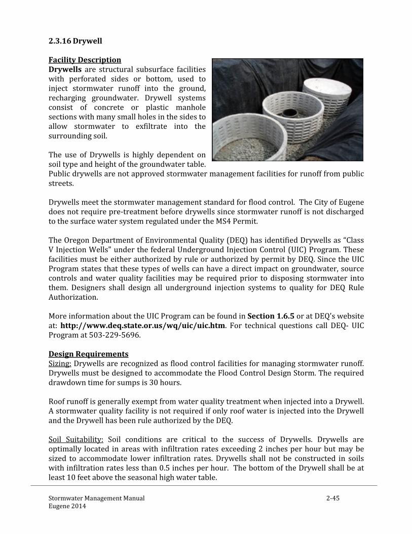
Stormwater Management Manual 2-45 Eugene 2014
2.3.16 Drywell Facility Description Drywells are structural subsurface facilities with perforated sides or bottom, used to inject stormwater runoff into the ground, recharging groundwater. Drywell systems consist of concrete or plastic manhole sections with many small holes in the sides to allow stormwater to exfiltrate into the surrounding soil. The use of Drywells is highly dependent on soil type and height of the groundwater table. Public drywells are not approved stormwater management facilities for runoff from public streets. Drywells meet the stormwater management standard for flood control. The City of Eugene does not require pre-treatment before drywells since stormwater runoff is not discharged to the surface water system regulated under the MS4 Permit. The Oregon Department of Environmental Quality (DEQ) has identified Drywells as “Class V Injection Wells" under the federal Underground Injection Control (UIC) Program. These facilities must be either authorized by rule or authorized by permit by DEQ. Since the UIC Program states that these types of wells can have a direct impact on groundwater, source controls and water quality facilities may be required prior to disposing stormwater into them. Designers shall design all underground injection systems to quality for DEQ Rule Authorization. More information about the UIC Program can be found in Section 1.6.5 or at DEQ's website at: http://www.deq.state.or.us/wq/uic/uic.htm. For technical questions call DEQ- UIC Program at 503-229-5696. Design Requirements Sizing: Drywells are recognized as flood control facilities for managing stormwater runoff. Drywells must be designed to accommodate the Flood Control Design Storm. The required drawdown time for sumps is 30 hours. Roof runoff is generally exempt from water quality treatment when injected into a Drywell. A stormwater quality facility is not required if only roof water is injected into the Drywell and the Drywell has been rule authorized by the DEQ. Soil Suitability: Soil conditions are critical to the success of Drywells. Drywells are optimally located in areas with infiltration rates exceeding 2 inches per hour but may be sized to accommodate lower infiltration rates. Drywells shall not be constructed in soils with infiltration rates less than 0.5 inches per hour. The bottom of the Drywell shall be at least 10 feet above the seasonal high water table.

Stormwater Management Manual 2-46 Eugene 2014
Dimension and Slopes: Drywells shall not be constructed on slopes greater than 10%. Setbacks: Drywells require 5 foot setbacks from the property lines and 10 foot setbacks from building foundations. Number: More than one Drywell may be interconnected in series. Minimum distance between Drywells shall be 25 feet. Materials Drywells shall be pre-cast concrete or manufactured plastics. Drywells shall meet structural requirements for overburden support and traffic loadings, if appropriate. H-20 live loads shall be accommodated for tanks and vaults under roadways and parking areas. Piping: Pipes shall be sized to convey the flood control design storm. Silt traps: Silt traps are strongly recommended on Drywell installations with no pre-treatment to extend the service life of the facility. Covers: Drywells may have flat tops, manhole cones or other covers that are appropriately rated for surface loads. Drywells shall have an access cover at finished grade for maintenance and inspections. Geotextile Fabric: Geotextile shall be required between the drainage rock and surrounding soils. Geotextile shall be required between the perforated sections of the sump and surrounding drainage rock if the size of perforations exceeds the diameter of drainage rock. Geotextile shall also be required to separate drainage layers if applicable. Drainage Rock: Drainage rock shall be 3/4-inch to 2-1/2-inch open graded aggregate.

Stormwater Management Manual 2-47 Eugene 2014
2.3.17 Soakage Trench Facility Description Soakage trenches are flood control devices injecting stormwater runoff into the ground recharging groundwater. Soakage trenches are linear excavations lined and backfilled with drain rock and gravel retaining runoff volumes as it exfiltrates into the surrounding soils. There are various components within the system – inlet piping, aggregate storage basin and perforated piping. The trench surface may be covered with grating, stone, sand, or a grassed cover with a surface inlet and may also be installed under hard surfaces such as driveways. The use of Soakage Trenches is highly dependent on soil type and the height of the groundwater table. Public soakage trenches are not approved as stormwater management facilities for runoff from public streets. Soakage Trenches meet the stormwater management standard for flood control. The City of Eugene does not require pre-treatment before drywells since stormwater runoff is not discharged to the surface water system regulated under the MS4 Permit. DEQ has identified Soakage Trenches as "Class V Injection Wells" under the federal Underground Injection Control (UIC) Program. These facilities must be classified as exempt, authorized by rule, or authorized by permit by DEQ. Since the UIC Program states that these types of wells can have a direct impact on groundwater, water quality treatment may be required before disposing stormwater into them. All Soakage Trenches must be registered with DEQ. Designers shall design all underground injection systems to quality for DEQ Rule Authorization.
More information about the UIC Program can be found in Section 1.6.5 or at DEQ's website at: http://www.deq.state.or.us/wq/uic/uic.htm. For technical questions call DEQ- UIC Program at 503-229-5696. Design Requirements Sizing: Soakage Trenches shall be sized to infiltrate the Flood Control Design Storm. The maximum impervious area to be served by a soakage trench is 15,000 SF. Minimum drawdown time for soakage trenches is 30 hours. Dimension and Slopes: Soakage Trenches shall not be constructed on slopes greater than 10%. Soakage trenches shall be laid level to retain uniform infiltration within the system. Trenches shall be a minimum 12” wide and the have a minimum 6” of cover from the drain rock or perforate pipe, whichever is higher) to finished grade.

Stormwater Management Manual 2-48 Eugene 2014
Soil Suitability: Soil conditions are critical to the success of Soakage Trenches. Soakage Trenches are optimally located in areas with infiltration rates exceeding 2 inches per hour but may be sized to accommodate lower infiltration rates. Soakage trenches shall not be constructed in soils with infiltration rates less than 0.5 inches per hour. Setbacks: Soakage Trenches require 5 foot setbacks from the property lines and 10 foot setbacks from building foundations. Trenches: A silt basin, cleanout, or inspection port shall be required upstream of the trench for inspection purposes. There shall be no less than 5’ of the infiltration medium and/or undisturbed soil between the bottom of the drain rock layer and any impervious layer (hard pan, bed rock, low permeability soils (0.5in/hr or less)). The bottom of the drain rock layer shall be no less than 5’ above seasonally high groundwater. Materials Drain Rock: The drain rock layer shall be no less than 12 inches. Drain rock shall be ¾ inches to 2-1/2inches washed open graded aggregate. Geotextile Fabric: Soakage tranches shall be wrapped in geotextile fabrics. Geotextile shall be required between the drainage layers and surrounding soils. Geotextile shall also be required to separate drainage layers.

Stormwater Management Manual 2-49 Eugene 2014
2.4 FACILITY SIZING APPROACHES Facilities sized under the Simplified Approach and Presumptive Approach complies with the City of Eugene’s Stormwater Flood Control, Stormwater Quality and Stormwater Flow Control requirements. 2.4.1 Simplified Approach (SIM Form 2013) The Simplified Approach uses simple area ratio calculations to size stormwater facilities and is provided on the SIM Form 2013 located in Appendix C. The Simplified Approach may be used when the impervious surface area is less than 15,000 square feet (.34 acre), including but not limited to: roofs, patios, parking areas, and driveways. This approach is a relatively easy process for selecting and sizing stormwater quality and flow control facilities and is intended to save the project time and expense. The Simplified Approach is best used for small residential and commercial development. It is not intended to be used on large, complex projects with multiple catchments or challenging soils and topography. The Simplified Approach is not allowed for public improvement projects. The Simplified Approach applies to surface vegetated facilities including:
• Filter Strips • Rain Gardens • Sand Filters • Stormwater Planters • Swales
Facilities may be sized using the Simplified Approach to comply either with sizing requirements for stormwater quality only or stormwater quality with flow control. Flood control sizing of facilities without an approved overflow must use the presumptive method with a measured infiltration rate. Infiltration testing standards are located in Appendix G. Projects with less than 2 inches per hour must use the sizing criteria in conjunction with underdrains and overflow to an approved point of discharge. Generalized assumptions were used when developing the SIM Form that may result in conservative sizing for some development sites. Manual users have the option to use the sizing factors as given on the SIM Form or use the Presumptive Approach to calculate an alternative facility size. SIM Form The SIM Form 2013 is provided in Appendix C; enter impervious area reduction technique areas (Contained Planters, Eco roofs, Pervious Pavements, and Tree Credits) on the SIM Form before calculating the required stormwater quality facility size.

Stormwater Management Manual 2-50 Eugene 2014
Simplified Approach Applications The minimum submittal requirements for the Simplified Approach are as follows:
Site Plan Cross Section and Details Complete SIM Form Operations & Maintenance Packet (Chapter 3) Landscape Plan
2.4.2 Presumptive Approach Projects that use this design approach are presumed to be in compliance with the City’s Stormwater Quality, Stormwater Flow Control, and/or Stormwater Flood Control requirements if the presented sizing and design requirements are followed. The Presumptive Approach allows the designer to factor in site-specific data and analysis size and configure stormwater facilities. Infiltration testing and detailed hydrologic calculations must be performed to adequately size the facility to achieve the desired goal. The Presumptive Approach can be used to size infiltration and filtration treatment facilities as well as to design hybrid facilities and treatment trains. A maximum infiltration rate of 2.5 inches per hour shall be allowed for design of the growing medium. The Presumptive Approach applies to surface infiltration and filtration treatment facilities including:
• Filter Strips • Ponds • Rain Gardens • Sand Filters • Stormwater Planters • Swales
The Presumptive Approach applies to mechanical treatment facilities and spill control manholes. The Presumptive Approach applies to subsurface facilities including:
• Structural Detention Facilities • Drywells • Soakage Trenches

Stormwater Management Manual 2-51 Eugene 2014
Eugene Presumptive Calculator Eugene’s Presumptive Calculator is an Excel spreadsheet available for applicants to use to determine the size of stormwater facilities under the Presumptive Approach. The spreadsheet may be downloaded from the City’s stormwater web page. Presumptive Approach Infiltration Testing The Presumptive Approach requires infiltration tests to be conducted before performing any design calculations. Three infiltration testing methods are available to determine the design infiltration rate:
• Open pit falling head • Encased falling head • Double-ring infiltrometer
A qualified professional must exercise judgment in the selection of the infiltration test method. Refer to Appendix G for the number and location of tests required. Depending on site conditions and the proposed facility location, the City may adjust the required number of tests. If the location and/or orientation of the proposed facility is revised during the design process, re-testing may be required. The design professional may assume a maximum infiltration rate of 2 inches per hour, withouth testing, based upon the identification of mapped Type A and B soils unless sizing to infiltrate the Flood Control Event. Facilities sized to infiltrate the Flood Control Event without an overflow to an approved point of discharge are required to use an infiltration rate that is half the measured infiltration rate or the maximum design infiltration rate, whichever is smaller. All other facility infiltration may be designed at the measured infiltration rate. Presumptive Approach Application The minimum submittal requirements for the Presumptive Approach are as follows:
• Scaled Site Plan • Cross Section and Details • Stormwater Analysis Report • Operations & Maintenance Packet • Landscape Plan
The stormwater report must be prepared by a licensed design professional. See Appendix H for submittal format and details.

Stormwater Management Manual 2-52 Eugene 2014
2.5 HYDROLOGIC ANALYSIS With the exception of facilities approved using the Simplified Approach, stormwater management facilities should be designed for stormwater quality, flow control and flood control using one of the hydrologic analysis methods described below. If one of the hydrologic analysis methods discussed below is not used, City staff must pre-approve the alternative method before the plans and calculations are submitted. Regardless of how the hydrologic calculations are performed, all hydrologic submittals shall include data necessary to facilitate the City’s review. Flow Rate Based Facilities: The Rational Method is the preferred analysis method for sizing flow rate based stormwater quality facilities. The following are flow rate based facilities:
• Swales • Filter Strips • Manufactured Treatment Devices • Spill Control Manholes
Flow Volume Based Facilities: The design professional may use the Santa Barbara Urban Hydrograph (SBUH) Type 1A – 24 hour, NRCS TR-55, HEC-1, or SWMM design analyses for sizing volume based facilities. Volume based stormwater quality facilities included in this Manual are required to use the pre-determined volume of 1.4 inches over 24 hours with a Vb/Vr ratio of 2 to be in presumptive compliance with stormwater quality standards and 3.6 inches over 24 hours with flood control standards for a 10-year storm event (drainage basins less than 40 acres). Ponds are flow volume based facilities.
• Swales • Rain Gardens • Sand Filters • Stormwater Planters
Combination Rate/Volume Facilities: Software design programs based on the SBUH Type 1A – 24 hour method, or a continuous simulation model with Eugene rainfall data, is the preferred analysis method for sizing of flow rate-based stormwater quality facilities that also rely on a storage volume component. When using SBUH, a 1.4 inch, 24-hour storm with NRCS type 1A rainfall distribution shall be used for stormwater quality design. When designing for flood control, the 5 year, 24 hour Flood Control Design Storm of 3.6 inches shall be used. The design professional may also use the NRCS TR-55, HEC-1, or SWMM.
• Swales • Rain Gardens • Sand Filters • Stormwater Planters • Soakage Trenches • Drywells

Stormwater Management Manual 2-53 Eugene 2014
Conveyance Conveyance channels and piping shall be shall be sized in accordance with the methods identified in the Flood Control Design Strom Tables located in Appendix K Hydrologic Analysis Method Resources The Santa Barbara Urban Hydrograph (SBUH) Method (see Appendix M) may be applied to small, medium, and large projects. It is a recommended method for completing the analysis necessary for designing flow control facilities when not using the Simplified Approach. The SCS TR-55 Method may be applied to small, medium, and large projects. This is also one of the recommended methods for completing hydrologic analysis necessary for designing flow control facilities when not using the Simplified Approach. (Refer to SCS Publication 210-VI-TR-55, Most Current Edition.) The HEC-1 Method may be used on medium and large projects. (Refer to the HEC User’s Manual.) The SWMM Method may be used on medium and large projects. (Refer to the SWMM User's Manual.)

Stormwater Management Manual 2-54 Eugene 2014
2.6 ACCESS FOR OPERATIONS AND MAINTENANCE Adequate access for operations and maintenance must be provided to all stormwater management facilities and their components. Public facilities shall have access routes at least 10 feet wide, not to exceed 10 percent in slope, and shall be located adjacent to public rights-of-way wherever feasible. Access routes greater than 100 feet in length shall provide a vehicle turn-around for the maintenance vehicles. Where structural surfaces are needed to support maintenance vehicles, access routes shall be constructed of gravel or other permeable paving surface where possible. Public facility vehicular access routes shall be designed for H-20 loading.

Stormwater Management Manual 2-55 Eugene 2014
2.7 OUTFALL DESIGN Outfalls should be located above the downstream ordinary high water level, unless a pipe velocity of 3’ per second can be maintained with the pipe outfall located below the water surface level. All outfalls shall be provided with a rock splash pad or other approved erosion control/energy dissipation measures. Rock protection at outfalls from small diameter pipes shall be as follows:
3” Pipe: 12” wide x 24” long x 2” deep, Average Stone Size = 1” 4” Pipe: 24” wide x 36” long x 4” deep, Average Stone Size = 2” 6” Pipe: 36” wide x 48” long x 6” deep, Average Stone Size = 4”
Rock protection at outfalls from pipes greater than 6 inches shall be engineered. Energy dissipation is required for flows greater than 20 fps. Design criteria for outfalls greater than 6” are located in Appendix F. Drainage ways and rivers may have steep slopes or banks and may have unstable landforms. Engineering analyses may be required to determine the stability of the stream or river bank.

Stormwater Management Manual 2-56 Eugene 2014
2.8 CONSTRUCTION CRITERIA This section provides general construction related requirements. Unless otherwise noted in the specific facility design criteria, compliance with the following construction criteria is required. 2.8.1 Public Stormwater Facilities Materials and construction of public facilities must be in compliance with the Eugene adopted Oregon Standard Specifications for Construction and Standard Drawings. 2.8.2 Site Preparation and Grading The location of all areas of future stormwater facilities should be clearly marked before site work begins. Infiltration and filtration treatment facilities areas should be fenced or covered to protect them from damage or misuse during construction and to prevent soil compaction during construction. No vehicular traffic, material storage, or heavy equipment are allowed within the infiltration treatment facility areas after site clearing and grading have been completed, except as needed to excavate, grade, and construct the facility. No stormwater facility areas should be used for dumping concrete, building materials, or other rubbish. Existing vegetation to be saved must be clearly marked and securely protected. If native plants are present, they should be salvaged and stored for replanting once construction is complete. Unwanted vegetation in the facility area should be removed during site preparation with equipment appropriate for the type of material and site conditions. Once the facility area is graded, all native subsoil must be tilled or ripped to a depth of 8” before installing the specified stormwater facility growing medium. No tilling should occur within the drip line of existing trees. After tilling is completed, no other construction traffic should be allowed in the facility area, except for planting and related work. All construction and other debris must be removed before the growing medium is placed. Surface drainage must be prevented from entering the facility during construction until the facility is fully installed and the contributing catchment area is stabilized. The contractor is responsible for protecting the facility from erosion until fully stabilized. 2.8.3 Erosion and Sedimentation Plans Appropriate erosion control measures must be used to protect facilities from sedimentation. The erosion and sediment control plan (ESCP; may also be called construction site management plan, CSMP) set should show the fencing layout for vegetation to be protected and the location of stormwater facilities. Location of all stockpiles must be indicated, including erosion protection measures per the City of Eugene’s Erosion Prevention Ordinance. 2.8.4 Piping For private facilities, piping must be cast iron, ductile iron, concrete, ABS, PVC, HDPE, corrugated metals or other ridgid pipe material. Three-inch pipe is required for facilities

Stormwater Management Manual 2-57 Eugene 2014
draining up to 1,500 square feet of impervious area; otherwise 4-inch pipe minimum is required. Pipe sizing, slope and installations must follow current Uniform Plumbing Code. For public facilities, all piping shall conform to The Public Improvement Design Standards (PIDS) Manual, City of Eugene Standard Specifications for Construction and standard drawings. 2.8.5 Gravel Drain Rock Drain rock may be required below the growing medium of a vegetated facility. Drain rock shall be washed open graded aggregate. The required depth of the drain rock for facilities designed with the Simplified Approach is 12 inches. The depth of the drain rock varies with the Presumptive Approach. Depending on native infiltration rates and the amount of stormwater being routed to the facility, 12 inches to a maximum of 48 inches of drain rock may be specified. Geotextiles shall be used to separate drain rock from native soils and the growing medium or sands. Geotextiles shall also be used to separate drainage layers with different gradations. 2.8.6 Geotextiles Geotextiles are often used in stormwater facilities. Non-woven fabrics make the best filters. Woven fabrics have greater strength and are less likely to clog. The design professional should specify the type of geotextile anywhere a geotextile is used.

Stormwater Management Manual 2-58 Eugene 2014
2.9 LANDSCAPE REQUIREMENTS Eugene’s stormwater management approach relies on the use of vegetated infiltration and filtration treatment facilities to comprehensively reduce runoff pollution and mitigate the volume, duration, time of concentration and rate of runoff. Stormwater quality facilities should be vegetated to the maximum extent feasible. Thriving vegetation is required in order to achieve compliance with the stormwater quality and flow control standards. This section addresses the landscape requirements that apply to all vegetated stormwater facilities, both private and public. Vegetation planting schemes and growing medium criteria are provided with specific facility design criteria. These requirements are based on the City’s experience and on standard design and construction methods in the landscape industry. 2.9.1 Relationship to Other Landscape Requirements When vegetated facilities are integrated into project landscape areas, they may also meet landscape standards set forth in Eugene Code Chapter 9. The benefits of integrated designs include construction cost savings, combined maintenance, aesthetic benefits, and the greater likelihood of maintaining long-term functionality. Where the plant material requirements of this manual and Chapter 9 differ, the designer must use the most restrictive requirement. When calculating quantities, fractions should be rounded to the higher whole number. Landscaping required by Chapter 9 may be counted toward meeting the facility-specific landscape requirements in this chapter if the plantings are located within the facility area. An integrated design may require changing the size of some site elements. 2.9.2 Public Easement and Rights of Way Vegetation Rain gardens, swales and stormwater planters constructed in public right of way shall be grassed or vegetated with plants having a mature height of 24” of less. Stormwater treatment facilities do not remove street tree requirements for new street construction and should be located to allow planting street trees outside of the stormwater treatment facility where possible. 2.9.3 Growing Medium The depth of the growing medium is specified in the specific facility design criteria. Unless otherwise provided in the specific facility design criteria, compliance with the following growing medium requirements is required for landscaping. For private facilities, the imported soil must be a sandy loam mixed with compost or a sand/soil/compost blend. It must be roughly one-third compost by volume, free-draining, and support plant growth. The compost must be derived from plant material; animal waste is not allowed. For public facilities, growing medium is required as specified topsoil in the City of Eugene Standard Specifications for Construction.

Stormwater Management Manual 2-59 Eugene 2014
Soil placement and planting should occur in conditions that do not result in over compaction or erosion. Temperature, moisture levels, and handling can have a significant influence on the infiltration rate of a facility and on plant survivability. 2.9.4 Vegetation Plants are critical to the performance of vegetated stormwater facilities and therefore must be selected for the appropriate soil, hydrologic, and site-specific conditions. The planting design should minimize the need for herbicides, fertilizers, pesticides, or soil amendments at any time before, during, and after construction and on a long-term basis. Plantings should also be designed to minimize the need for mowing, pruning, and irrigation. Plant species that have demonstrated their ability to withstand the “moist to wet” and “moist to dry” zones in stormwater facilities are provided in Appendix D. Applicants may select plants not shown on these lists, but are encouraged to research how successful the plants will survive in the planned stormwater facility. Because portions of vegetated facilities areas are designed to accommodate inundation through the wet periods of the year, it is imperative for the designer to delineate the wet zone and develop a planting plan in accordance with the level of inundation/saturation. Stormwater facilities are expected to have a “moist to wet” zone that is saturated through most of the year along the bottom of the facility. The side slopes of the facilities are less frequently inundated and are delineated as the “moist to dry” zone within 18” of the bottom to the top of the facility slope. Planting plans must be specific to the designated zones. Plants must be healthy and vigorous when planted. Within 2 years, the survival rate of vegetation must be sufficient to maintain minimum coverage requirements. If the survival rate falls below this threshold, additional plants sufficient to meet coverage requirements must be installed. The number of additional plants required should be based on the mortality rate of the initial planting. Structural components such as chain link fence, concrete bulkheads, outfalls, riprap, gabions, large steel grates, pipe, blank retaining walls, vault lids, and access roads should be screened from view by vegetation. The quantities and spacing of plant material required for each facility should provide sufficient screening. Attention should be paid to site conditions that may require adjustments to the planting plan, including the need for additional trees and shrubs. The intent of this requirement is not to dictate a specific solution such as a linear hedge. The planting plan must indicate the location of all landscape elements, including size, spacing, and species of all proposed plantings and existing plants and trees to be preserved. The plant list must include the botanical and common name, size at time of planting, quantity, type of container, evergreen or deciduous, and other information in accordance with the facility-specific planting section and landscape industry standards.

Stormwater Management Manual 2-60 Eugene 2014
Depending on when stormwater will be routed to the facility, planting should preferably occur in the dormant season. For best results, planting should occur in the spring (March) or early fall (September through October). 2.9.5 Vegetation Coverage Facilities shall be fully vegetated and stabilized prior to water entering the facility. Following the establishment period, vegetated stormwater facilities must maintain 90% coverage to ensure stormwater treatment. All methods must have soils stabilized in accordance with the City of Eugene’s Erosion Prevention Ordinance. 2.9.6 Grass Coverage Grass species must be sturdy, inundation and drought resistant, easy to establish and able to spread after establishment. A thick root structure is necessary to control weed growth and prevent erosion. Grasses shall have 100% coverage to ensure stormwater treatment. Grass seed shall be applied at the rates specified by the suppliers. If plant establishment cannot be achieved with seeding prior to the completion of the project, the contractor shall at a minimum protect the facility against erosion by installing erosion blankets before water is allowed to enter the facility. 2.9.7 Mulch Non-floating bark, well-aged compost, washed pea gravel, river run rock or open graded rock up to 3” thick is recommended for most stormwater facilities. It should not be over-applied. Care should be given in the selection and placement of mulch material to avoid clogging inlets or outlets or otherwise escaping the facility. At the time of final inspection, all surface area soils should be covered with plants and/or mulch sufficient to prevent erosion. 2.9.8 Irrigation Permanent irrigation systems are allowed for private facilities, but designers are encouraged to minimize the need for permanent irrigation. Innovative methods for watering vegetation are encouraged. Temporary irrigation systems for plant establishment are acceptable for public and private facilities. Permanent irrigation systems are not allowed for public facilities unless approved by the City of Eugene. Temporary irrigation systems or alternative methods of irrigation for landscape establishment should be specified when applicable. 2.9.9 Preventing Pollutants Projects must be designed to minimize the need for toxic or potentially polluting materials such as herbicides, pesticides, fertilizers, or petroleum-based fuels within the facility area before, during, and after construction. Mechanical means of weed control should be used were ever possible to reduce external pollutant loading. Materials that could leach pollutants or pose a hazard to people and wildlife must not be used as components of a stormwater facility. Some examples of these materials are

Stormwater Management Manual 2-61 Eugene 2014
chemically treated railroad ties and lumber and galvanized metals. Many alternatives to these materials are available.