chapter 14 superposition and standing waves 1. waves vs. particles particles have zero sizewaves...
TRANSCRIPT
Chapter 14
Superposition and
Standing Waves
1
Waves vs. Particles
Particles have zero size
Waves have a characteristic size – their wavelength
Multiple particles must exist at different locations
Multiple waves can combine at one point in the same medium – they can be present at the same location
2
Superposition Principle
• If two or more traveling waves are moving through a medium and combine at a given point, the resultant position of the element of the medium at that point is the sum of the positions due to the individual waves
• Waves that obey the superposition principle are linear waves – In general, linear waves have amplitudes much smaller than
their wavelengths
Slide 3
Superposition Example
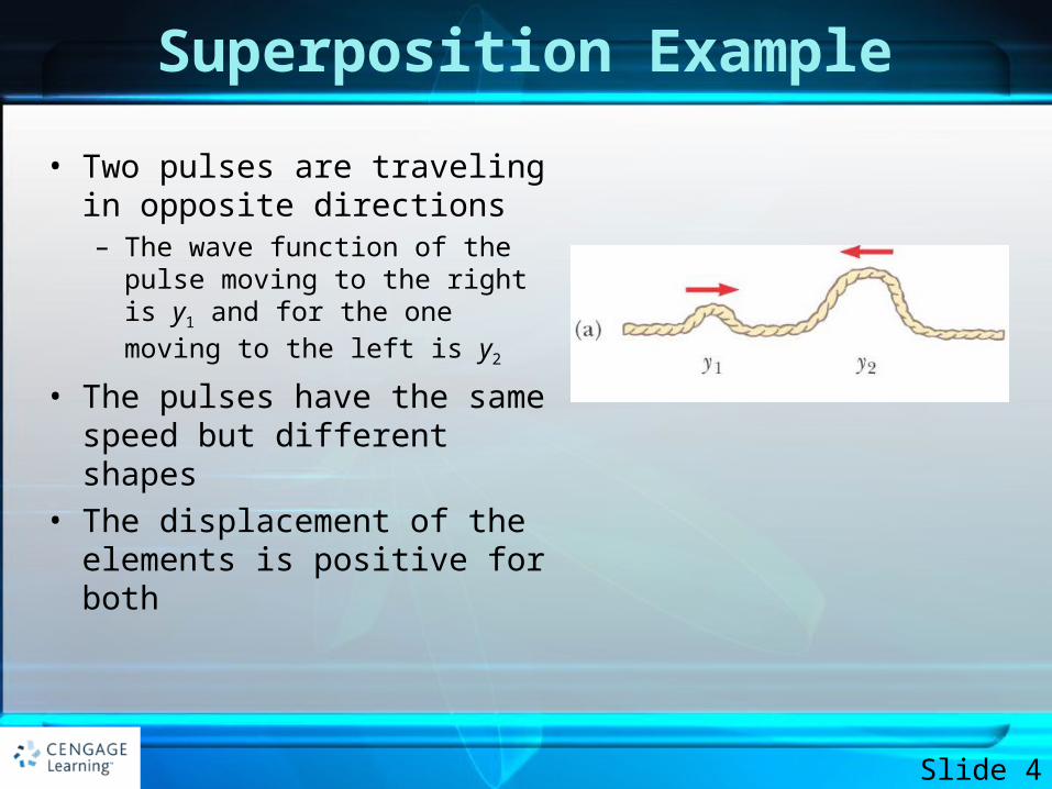
• Two pulses are traveling in opposite directions– The wave function of the pulse
moving to the right is y1 and for the one moving to the left is y2
• The pulses have the same speed but different shapes
• The displacement of the elements is positive for both
Slide 4
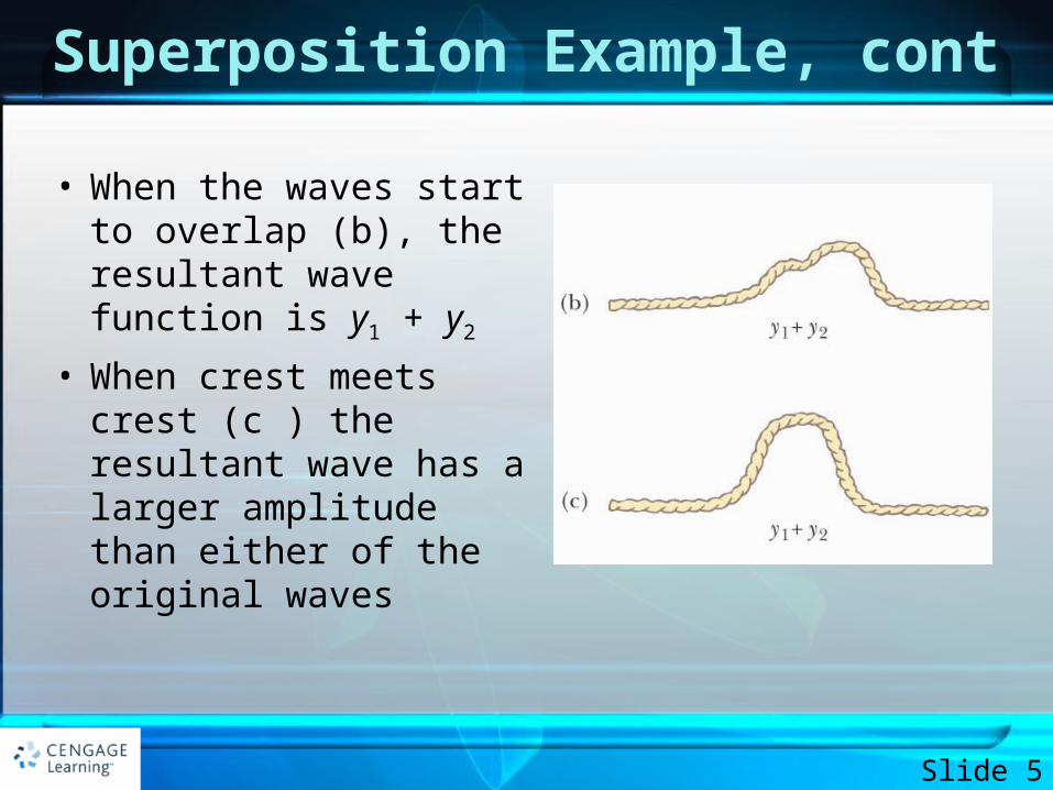
Superposition Example, cont
• When the waves start to overlap (b), the resultant wave function is y1 + y2
• When crest meets crest (c ) the resultant wave has a larger amplitude than either of the original waves
Slide 5
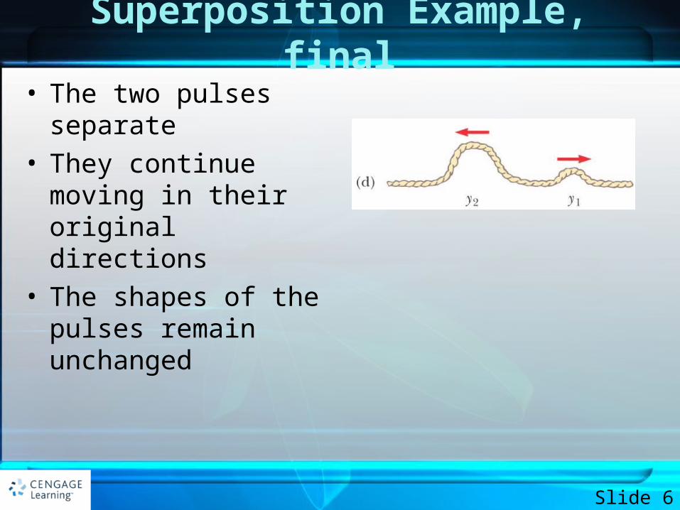
Superposition Example, final
• The two pulses separate• They continue moving in
their original directions• The shapes of the pulses
remain unchanged
Slide 6
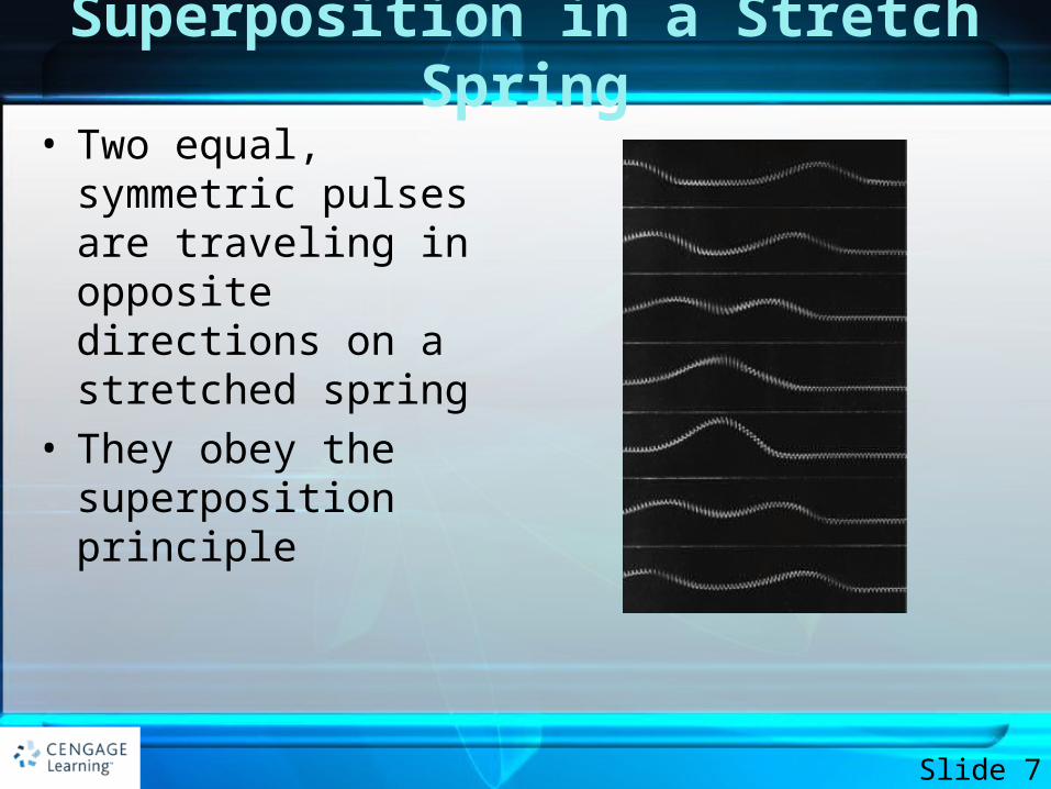
Superposition in a Stretch Spring
• Two equal, symmetric pulses are traveling in opposite directions on a stretched spring
• They obey the superposition principle
Slide 7
Superposition and Interference
• Two traveling waves can pass through each other without being destroyed or altered– A consequence of the superposition principle
• The combination of separate waves in the same region of space to produce a resultant wave is called interference
Slide 8
Types of Interference• Constructive interference occurs when the
displacements caused by the two pulses are in the same direction– The amplitude of the resultant pulse is greater than either
individual pulse
• Destructive interference occurs when the displacements caused by the two pulses are in opposite directions– The amplitude of the resultant pulse is less than either
individual pulse
Slide 9
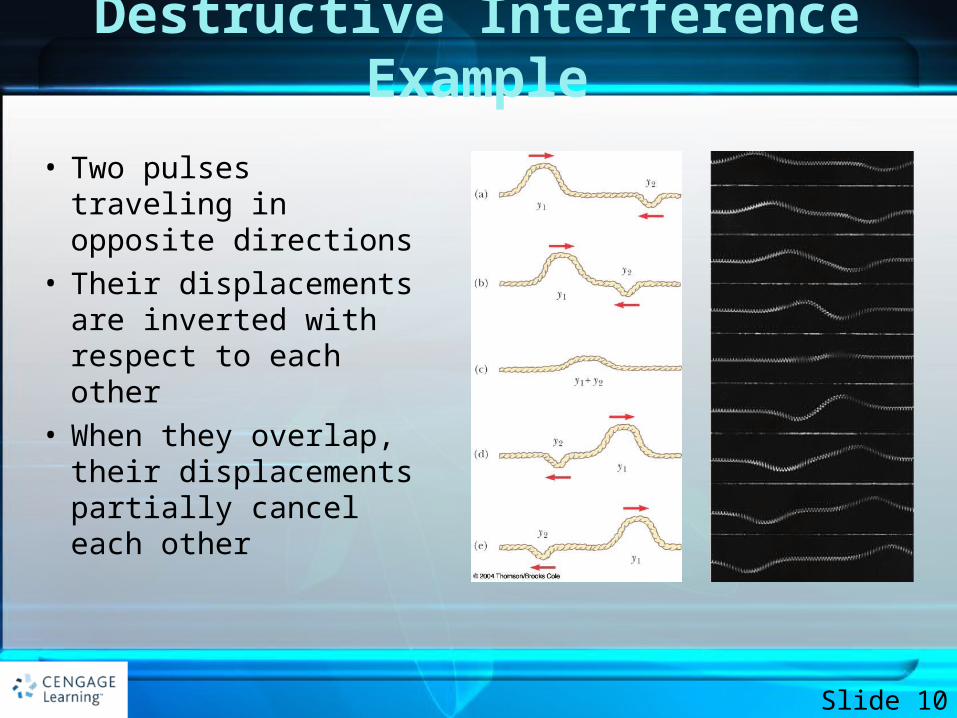
Destructive Interference Example
• Two pulses traveling in opposite directions
• Their displacements are inverted with respect to each other
• When they overlap, their displacements partially cancel each other
Slide 10
Superposition of Sinusoidal Waves
• Assume two waves are traveling in the same direction, with the same frequency, wavelength and amplitude
• The waves differ in phase• y1 = A sin (kx - t)• y2 = A sin (kx - t + )• y = y1+y2
= 2A cos (/2) sin (kx - t + /2)
Slide 11
Superposition of Sinusoidal Waves, cont
• The resultant wave function, y, is also sinusoidal• The resultant wave has the same frequency and
wavelength as the original waves• The amplitude of the resultant wave is 2A cos
(/2) • The phase of the resultant wave is /2
Slide 12
Sinusoidal Waves with Constructive Interference
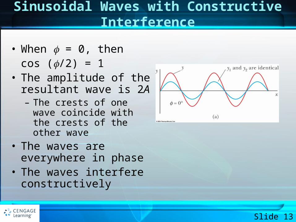
• When = 0, then cos (/2) = 1
• The amplitude of the resultant wave is 2A– The crests of one wave
coincide with the crests of the other wave
• The waves are everywhere in phase
• The waves interfere constructively
Slide 13
Sinusoidal Waves with Destructive Interference
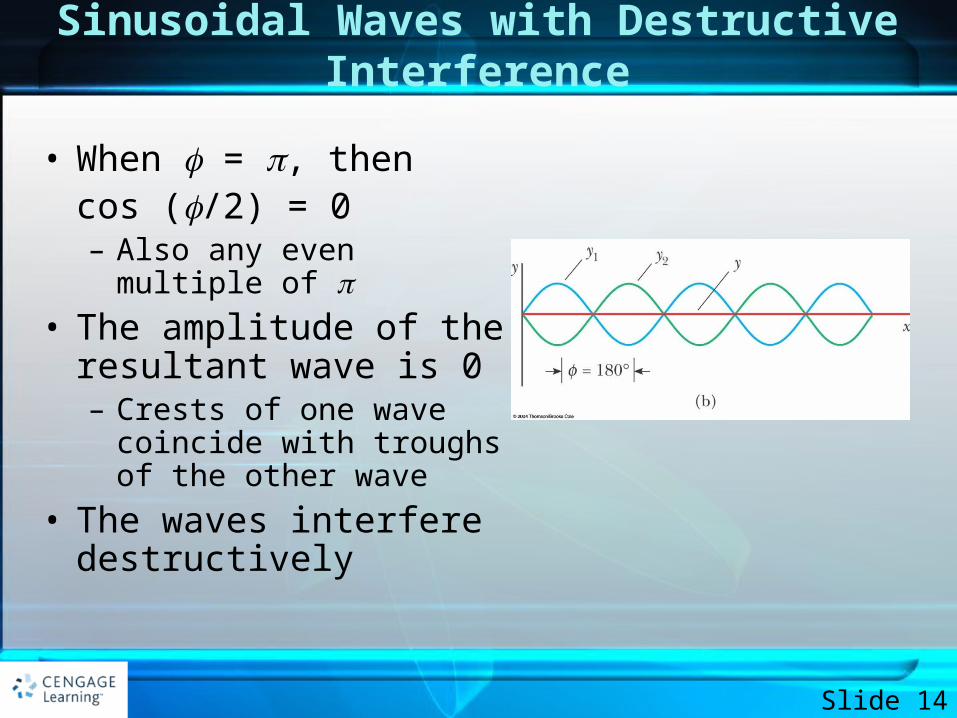
• When = , then cos (/2) = 0– Also any even multiple of
• The amplitude of the resultant wave is 0– Crests of one wave coincide
with troughs of the other wave
• The waves interfere destructively
Slide 14
Standing Waves
• Assume two waves with the same amplitude, frequency and wavelength, traveling in opposite directions in a medium
• y1 = A sin (kx – t) and y2 = A sin (kx + t) • They interfere according to the superposition
principle
Slide 15
Standing Waves, cont
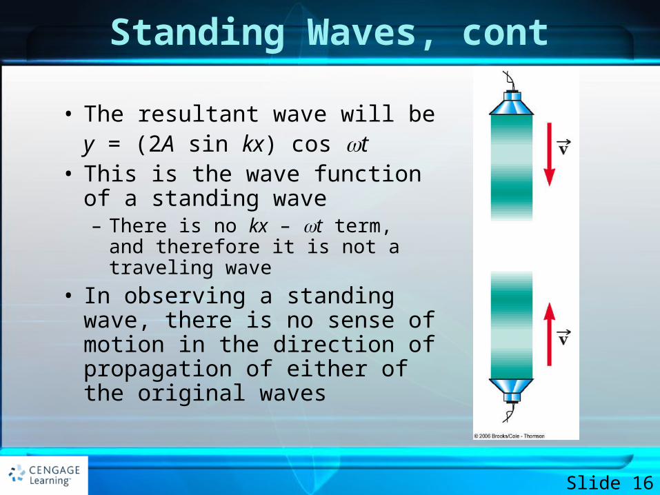
• The resultant wave will be y = (2A sin kx) cos t
• This is the wave function of a standing wave– There is no kx – t term, and
therefore it is not a traveling wave
• In observing a standing wave, there is no sense of motion in the direction of propagation of either of the original waves
Slide 16
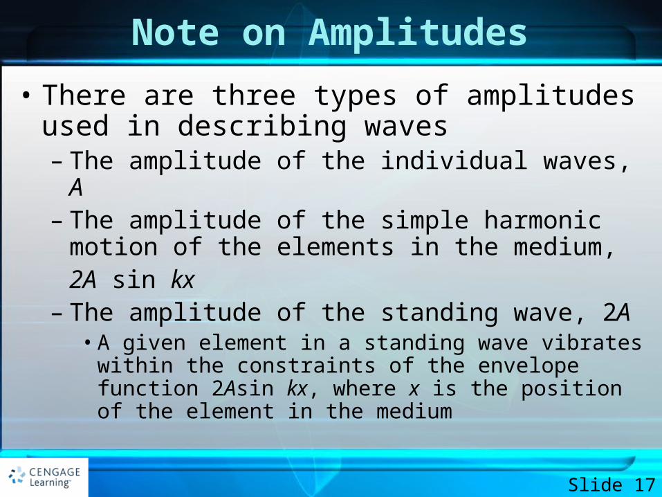
Note on Amplitudes
• There are three types of amplitudes used in describing waves– The amplitude of the individual waves, A– The amplitude of the simple harmonic motion of the
elements in the medium,2A sin kx
– The amplitude of the standing wave, 2A• A given element in a standing wave vibrates within the
constraints of the envelope function 2Asin kx, where x is the position of the element in the medium
Slide 17
Standing Waves, Particle Motion
• Every element in the medium oscillates in simple harmonic motion with the same frequency,
• However, the amplitude of the simple harmonic motion depends on the location of the element within the medium– The amplitude will be 2A sin kx
Slide 18
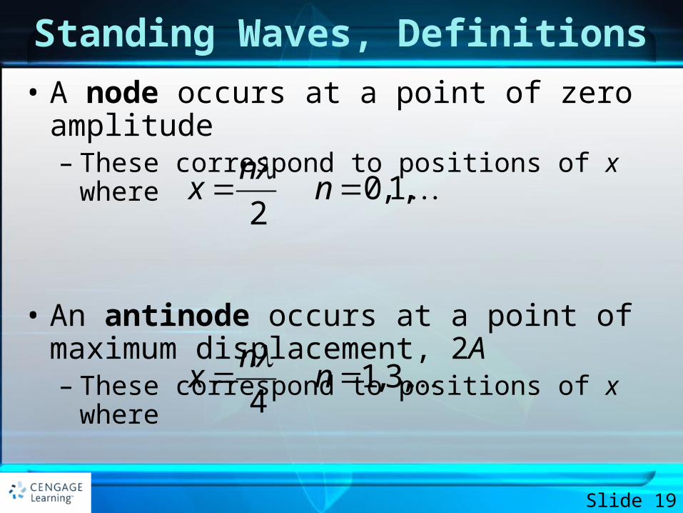
Standing Waves, Definitions
• A node occurs at a point of zero amplitude– These correspond to positions of x where
• An antinode occurs at a point of maximum displacement, 2A– These correspond to positions of x where
Slide 19
0,1,2
nx n
1,3,4
nx n
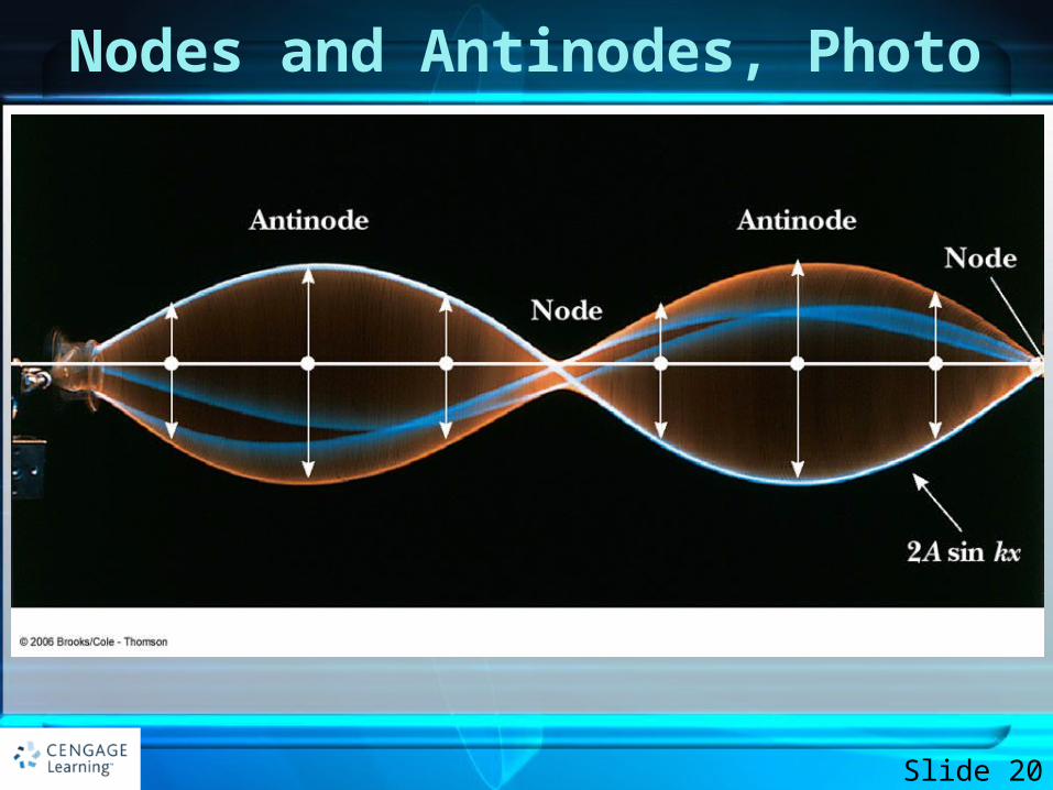
Nodes and Antinodes, Photo
Slide 20
Features of Nodes and Antinodes
• The distance between adjacent antinodes is /2
• The distance between adjacent nodes is /2
• The distance between a node and an adjacent antinode is /4
Slide 21
Nodes and Antinodes, cont
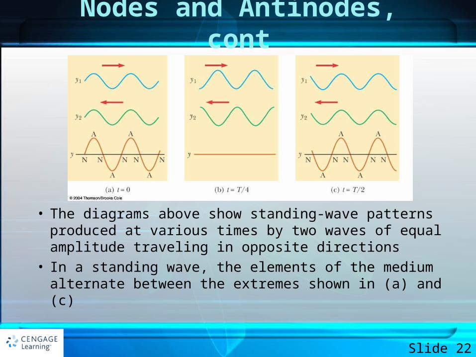
• The diagrams above show standing-wave patterns produced at various times by two waves of equal amplitude traveling in opposite directions
• In a standing wave, the elements of the medium alternate between the extremes shown in (a) and (c)
Slide 22
EXAMPLE 14.2 Formation of a Standing Wave
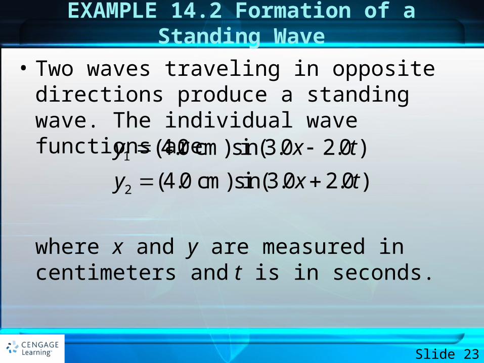
• Two waves traveling in opposite directions produce a standing wave. The individual wave functions are
where x and y are measured in centimeters and t is in seconds.
Slide 23
1
2
(4.0 cm)sin(3.0 2.0 )
(4.0 cm)sin(3.0 2.0 )
y x t
y x t
EXAMPLE 14.2 Formation of a Standing Wave
• A. Find the amplitude of the simple harmonic motion of the element of the medium located at x = 2.3 cm.
• B. Find the positions of the nodes and antinodes if one end of the string is at x = 0.
Slide 24
Solution - A
• The waves described by the given equations are identical except for their directions of travel, so they indeed combine to form a standing wave as discussed in this section. We can represent the waves graphically by the blue and green curves in Figure 14.8.
Slide 25
Solution - A
• We will substitute values in to equations developed in this section, so we categorize this example as a substitution problem.
• From the equations for the waves, we see that A = 4.0 cm, k = 3.0 rad/cm, and = 2.0 rad/s. Use Equation 14.3 to write an expression for the standing wave:
Slide 26
Solution - A
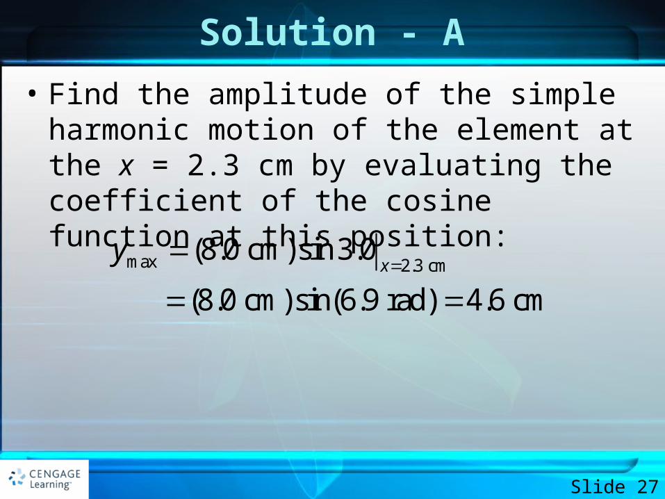
• Find the amplitude of the simple harmonic motion of the element at the x = 2.3 cm by evaluating the coefficient of the cosine function at this position:
Slide 27
max 2.3 cm(8.0 cm)sin 3.0
(8.0 cm)sin(6.9 rad) 4.6 cmx
y
Solution - B
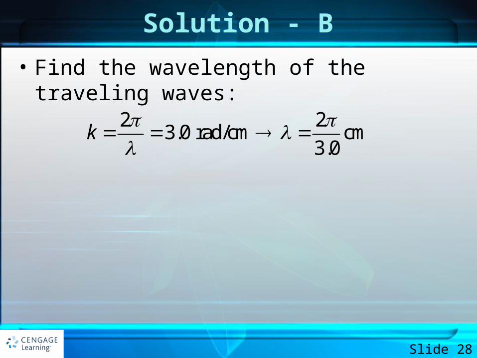
• Find the wavelength of the traveling waves:
Slide 28
2 23.0 rad/cm cm
3.0k
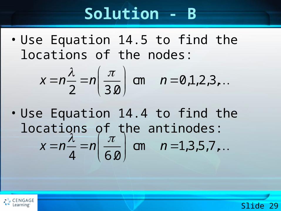
Solution - B
• Use Equation 14.5 to find the locations of the nodes:
• Use Equation 14.4 to find the locations of the antinodes:
Slide 29
cm 0,1,2,3,2 3.0
x n n n
cm 1,3,5,7,4 6.0
x n n n
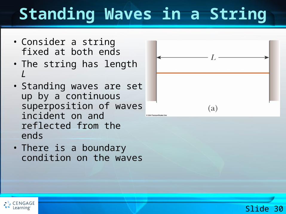
Standing Waves in a String
• Consider a string fixed at both ends
• The string has length L• Standing waves are set up
by a continuous superposition of waves incident on and reflected from the ends
• There is a boundary condition on the waves
Slide 30
Standing Waves in a String, 2
• The ends of the strings must necessarily be nodes– They are fixed and therefore must have zero displacement
• The boundary condition results in the string having a set of normal modes of vibration– Each mode has a characteristic frequency– The normal modes of oscillation for the string can be described
by imposing the requirements that the ends be nodes and that the nodes and antinodes are separated by /4
Slide 31
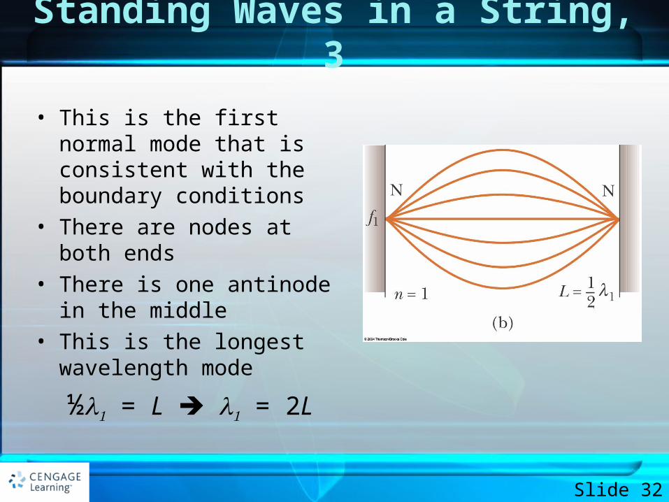
Standing Waves in a String, 3
• This is the first normal mode that is consistent with the boundary conditions
• There are nodes at both ends
• There is one antinode in the middle
• This is the longest wavelength mode
½ = L = 2L
Slide 32
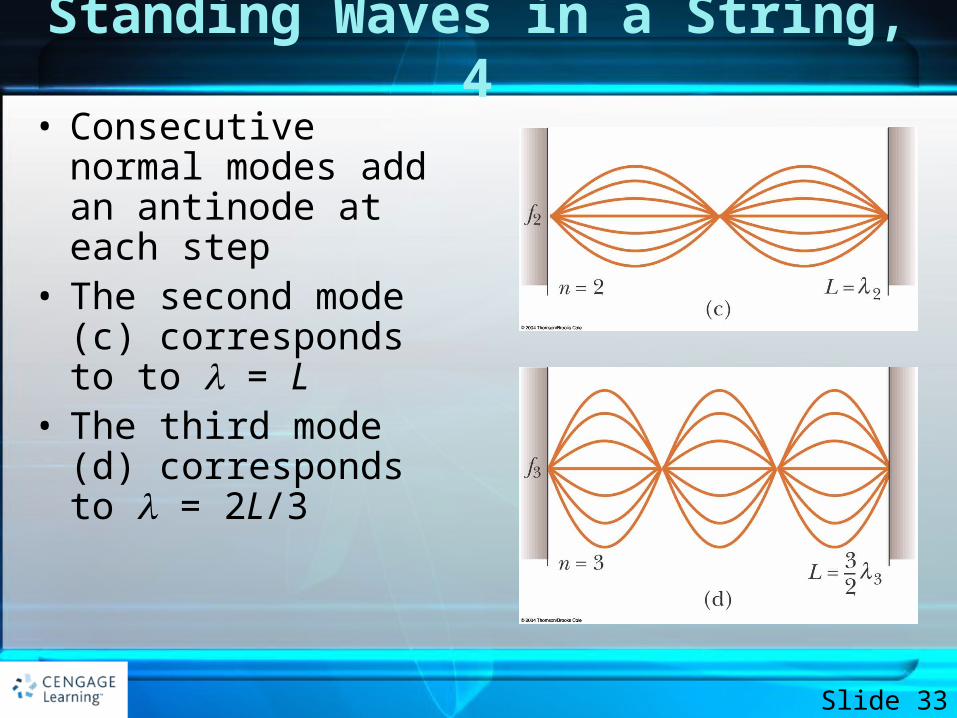
Standing Waves in a String, 4• Consecutive normal
modes add an antinode at each step
• The second mode (c) corresponds to to = L
• The third mode (d) corresponds to = 2L/3
Slide 33
Standing Waves on a String, Summary
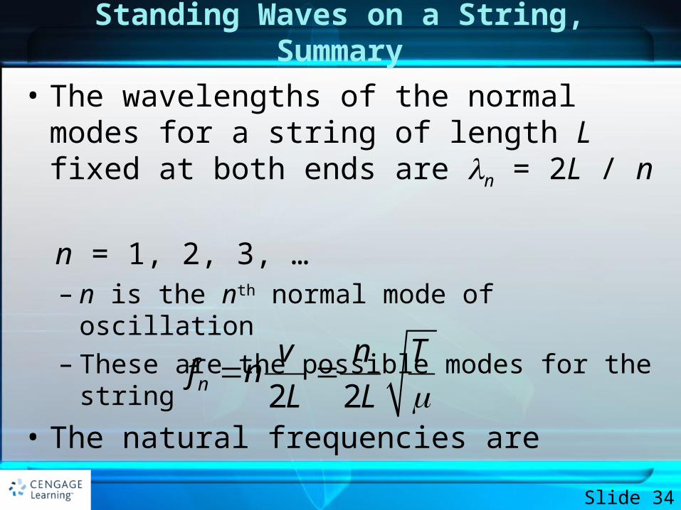
• The wavelengths of the normal modes for a string of length L fixed at both ends are n = 2L / n
n = 1, 2, 3, … – n is the nth normal mode of oscillation– These are the possible modes for the string
• The natural frequencies are
Slide 34
2 2n
v n Tf n
L L
Quantization
• This situation, in which only certain frequencies of oscillation are allowed, is called quantization
• Quantization is a common occurrence when waves are subject to boundary conditions
Slide 35
Waves on a String, Harmonic Series• The fundamental frequency corresponds to n = 1
– It is the lowest frequency, ƒ1
• The frequencies of the remaining natural modes are integer multiples of the fundamental frequency– ƒn = nƒ1
• Frequencies of normal modes that exhibit this relationship form a harmonic series
• The various frequencies are called harmonics
Slide 36
Musical Note of a String
• The musical note is defined by its fundamental frequency
• The frequency of the string can be changed by changing either its length or its tension
• The linear mass density can be changed by either varying the diameter or by wrapping extra mass around the string
Slide 37
Harmonics, Example
• A middle “C” on a piano has a fundamental frequency of 262 Hz. What are the next two harmonics of this string?– ƒ1 = 262 Hz
– ƒ2 = 2ƒ1 = 524 Hz
– ƒ3 = 3ƒ1 = 786 Hz
Slide 38
EXAMPLE 14.3 Give Me a C Note.
• The middle C string on a piano has a fundamental frequency of 262 Hz, and the string for the first A above middle C has a fundamental frequency of 440 Hz.
• A. Calculate the frequencies of the next two harmonics of the C string.
• B. If the A and C strings have the same linear mass density and length L, determine the ratio of tensions in the two strings.
Slide 39
Solution - A
• Remember that the harmonics of a vibrating string have frequencies that are related by integer multiples of the fundamental.
Slide 40
Solution - A
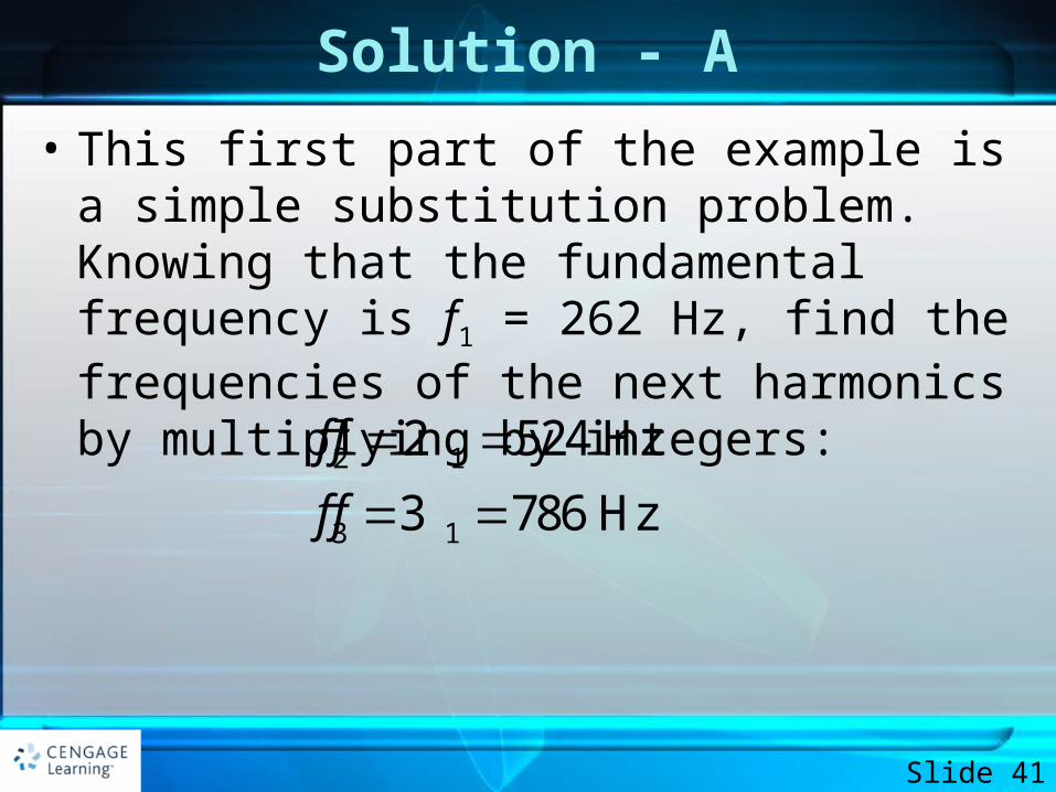
• This first part of the example is a simple substitution problem. Knowing that the fundamental frequency is f1 = 262 Hz, find the frequencies of the next harmonics by multiplying by integers:
Slide 41
2 1
3 1
2 524 Hz
3 786 Hz
f f
f f
Solution - B
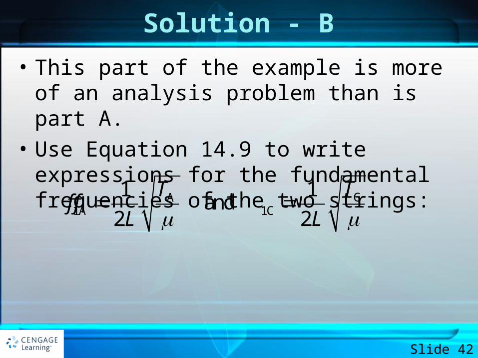
• This part of the example is more of an analysis problem than is part A.
• Use Equation 14.9 to write expressions for the fundamental frequencies of the two strings:
Slide 42
CA1A 1C
1 1 and
2 2
TTf f
L L
Solution - B
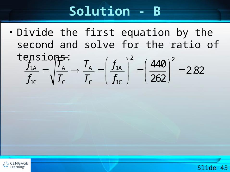
• Divide the first equation by the second and solve for the ratio of tensions:
Slide 43
2 2
1A A A 1A
1C C C 1C
4402.82
262
f T T f
f T T f
Solution - B
• If the frequencies of piano strings were determined solely by tension, this result suggests that the ratio of tensions from the lowest string to the highest string on the piano would be enormous. Such large tensions would make it difficult to design a frame to support the strings. In reality, the frequencies of piano strings vary due to additional parameters, including the mass per unit length and the length of the string. The What If? below explores a variation in length.
Slide 44
WHAT IF?
• If you look inside a real piano, you’ll see that the assumption made B is only partially true. The strings are not likely to have the same length. The string densities for the given notes might be equal, but suppose the length of the A string is only 64% of the length of the C string. What is the ratio of their tensions?
Slide 45
Answer
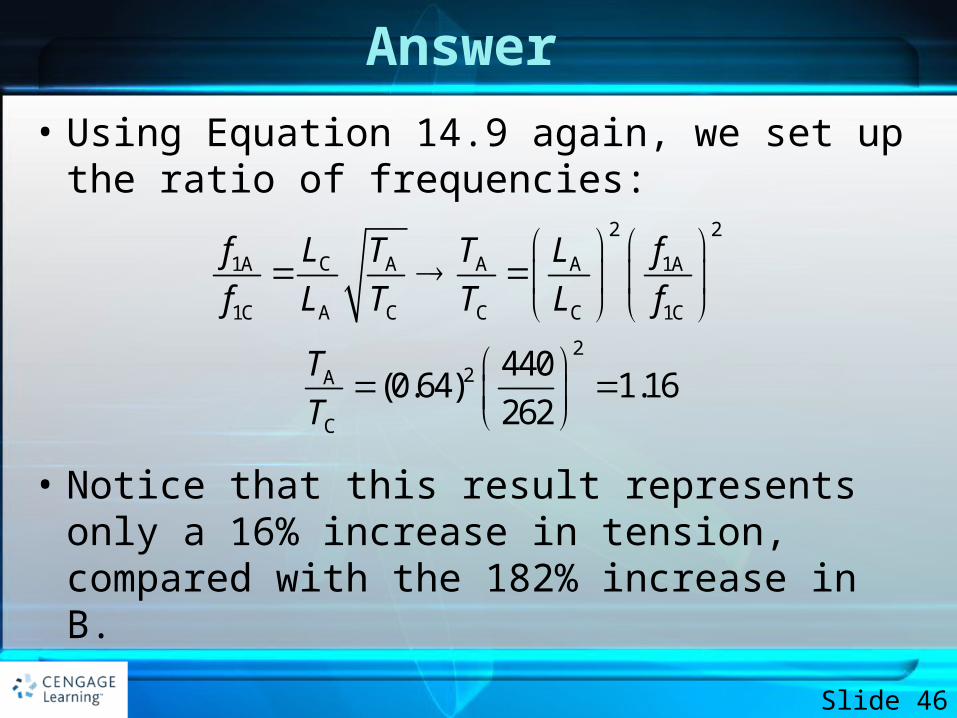
• Using Equation 14.9 again, we set up the ratio of frequencies:
• Notice that this result represents only a 16% increase in tension, compared with the 182% increase in B.
Slide 46
2 2
C1A A A A 1A
1C A C C C 1C
22A
C
440 (0.64) 1.16
262
Lf T T L f
f L T T L f
T
T
EXAMPLE 14.4 Changing String Vibration with Water
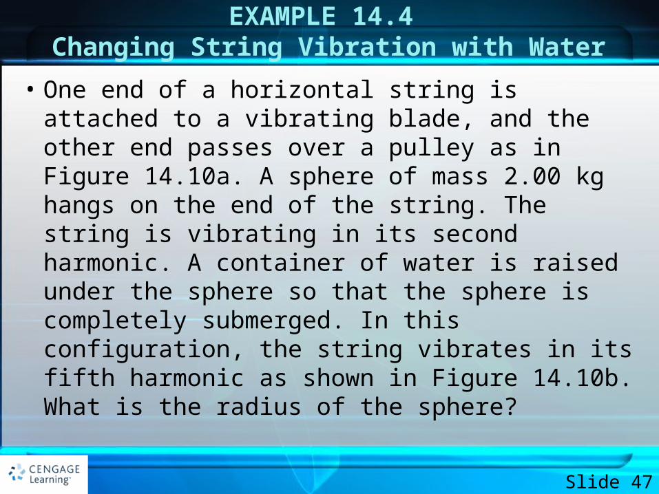
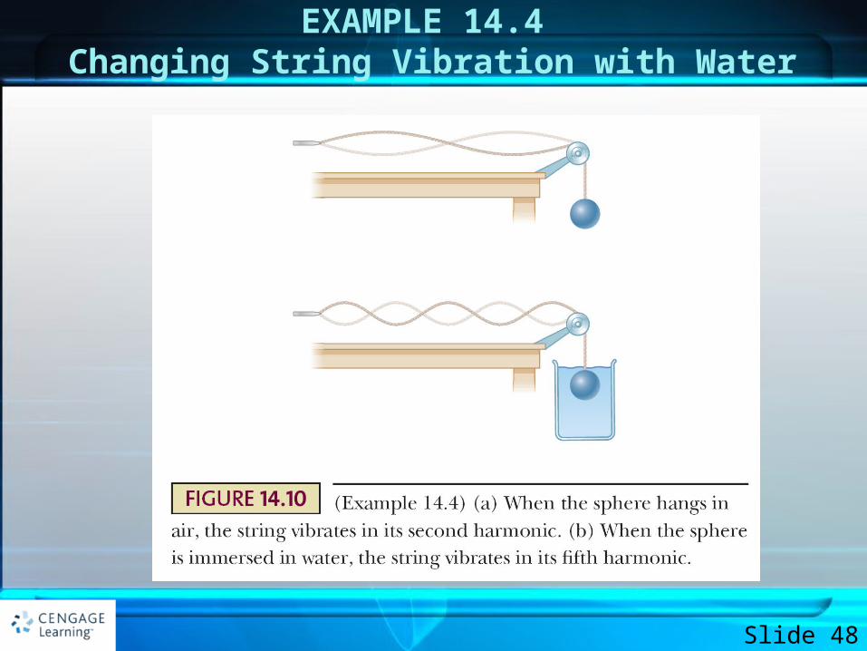
• One end of a horizontal string is attached to a vibrating blade, and the other end passes over a pulley as in Figure 14.10a. A sphere of mass 2.00 kg hangs on the end of the string. The string is vibrating in its second harmonic. A container of water is raised under the sphere so that the sphere is completely submerged. In this configuration, the string vibrates in its fifth harmonic as shown in Figure 14.10b. What is the radius of the sphere?
Slide 47
EXAMPLE 14.4 Changing String Vibration with Water
Slide 48
Solution
• Imagine what happens when the sphere is immersed in the water. The buoyant force acts upward on the sphere, reducing the tension in the string. The change in tension causes a change in the speed of waves on the string, which in turn causes a change in the wavelength. This altered wavelength results in the string vibrating in its fifth normal mode rather than the second.
Slide 49
Solution
• The hanging sphere is modeled as a particle in equilibrium. One of the forces acting on it is the buoyant force from the water. We also apply the waves under boundary conditions model to the string.
Slide 50
Solution
• Apply the particle in equilibrium model to the sphere in Figure 14.10a, identifying T1 as the tension in the string as the sphere hangs in air:
Slide 51
1
1
0F T mg
T mg
Solution
• Apply the particle in equilibrium model to the sphere in Figure 14.l0b, where T2 is the tension in the string as the sphere is immersed in water:
Slide 52
2
2
0
(1)
T B mg
B mg T
Solution
• The desired quantity, the radius of the sphere, will appear in the expression for the buoyant force B. Before proceeding in this direction, however, we must evaluate T2 from the information about the standing wave.
Slide 53
Solution
• Write the equation for the frequency of a standing wave on a string (Eq. 14.8) twice, once before the sphere is immersed and once after. Notice that the frequency f is the same in both cases because it is determined by the vibrating blade. In addition, the linear mass density m and the length L of the vibrating portion of the string are the same in both cases.
Slide 54
Solution
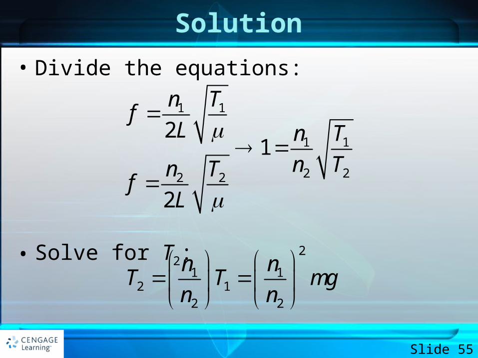
• Divide the equations:
• Solve for T2:
Slide 55
1 1
1 1
2 22 2
21
2
n Tf
L n T
n Tn Tf
L
2
1 12 1
2 2
n nT T mg
n n
Solution
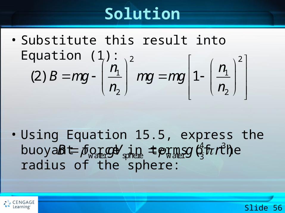
• Substitute this result into Equation (1):
• Using Equation 15.5, express the buoyant force in terms of the radius of the sphere:
Slide 56
2 2
1 1
2 2
(2) 1n n
B mg mg mgn n
4 3water sphere water 3
( )B gV g r
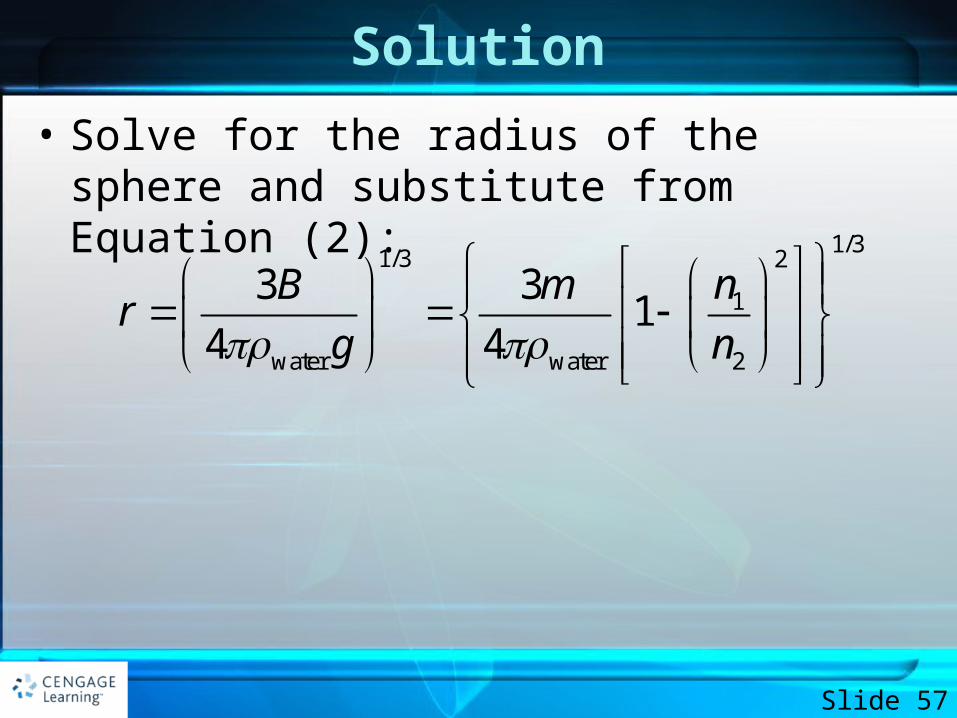
Solution
• Solve for the radius of the sphere and substitute from Equation (2):
Slide 57
1/31/3 2
1
water water 2
3 31
4 4
nB mr
g n
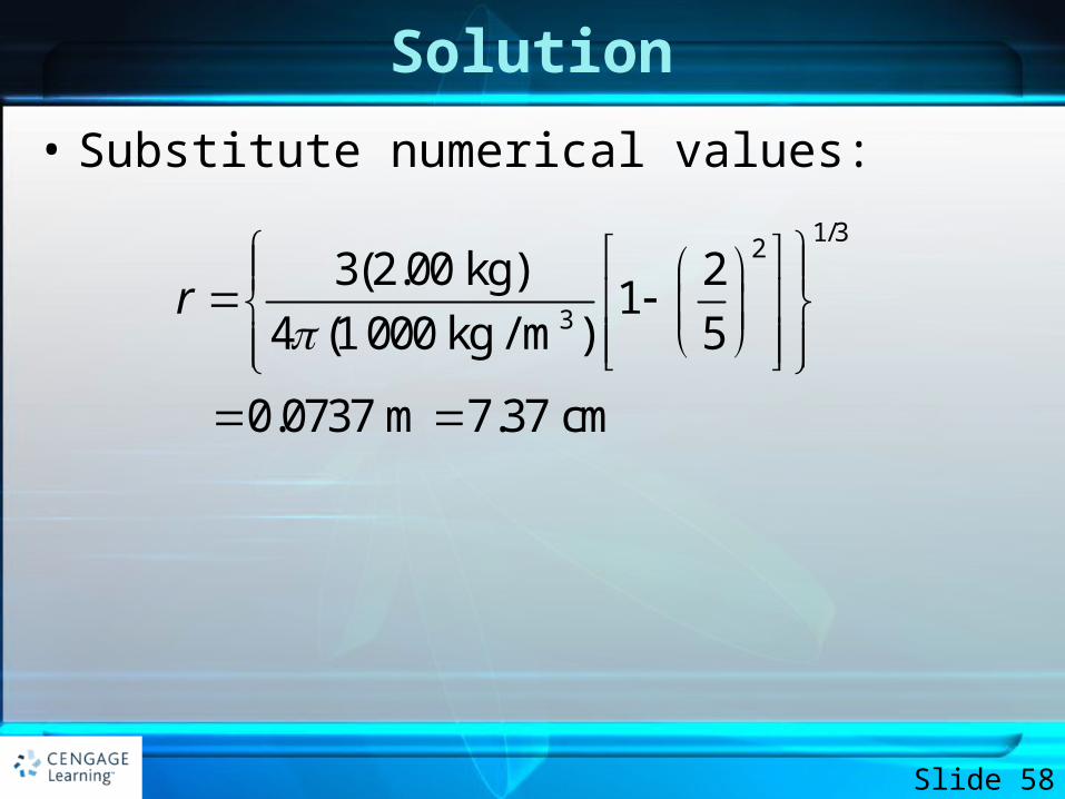
Solution
• Substitute numerical values:
Slide 58
1/32
3
3(2.00 kg) 21
4 (1 000 kg / m ) 5
0.0737 m 7.37 cm
r
Solution
• Notice that only certain radii of the sphere will result in the string vibrating in a normal mode; the speed of waves on the string must be changed to a value such that the length of the string is an integer multiple of half wavelengths. This limitation is a feature of the quantization that was introduced earlier in this chapter: the sphere radii that cause the string to vibrate in a normal mode are quantized.
Slide 59
Standing Waves in Air Columns
• Standing waves can be set up in air columns as the result of interference between longitudinal sound waves traveling in opposite directions
• The phase relationship between the incident and reflected waves depends upon whether the end of the pipe is opened or closed
Slide 60
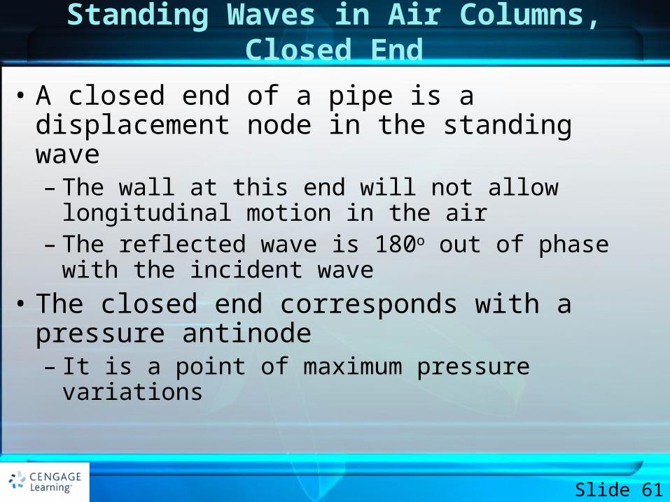
Standing Waves in Air Columns, Closed End
• A closed end of a pipe is a displacement node in the standing wave– The wall at this end will not allow longitudinal motion
in the air– The reflected wave is 180o out of phase with the
incident wave
• The closed end corresponds with a pressure antinode– It is a point of maximum pressure variations
Slide 61
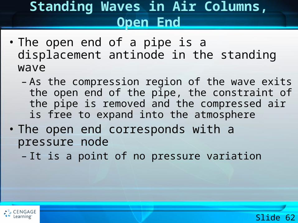
Standing Waves in Air Columns, Open End
• The open end of a pipe is a displacement antinode in the standing wave– As the compression region of the wave exits the open
end of the pipe, the constraint of the pipe is removed and the compressed air is free to expand into the atmosphere
• The open end corresponds with a pressure node– It is a point of no pressure variation
Slide 62
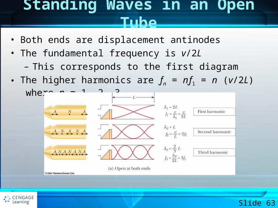
Standing Waves in an Open Tube
• Both ends are displacement antinodes
• The fundamental frequency is v/2L
– This corresponds to the first diagram
• The higher harmonics are ƒn = nƒ1 = n (v/2L) where n = 1, 2, 3, …
Slide 63
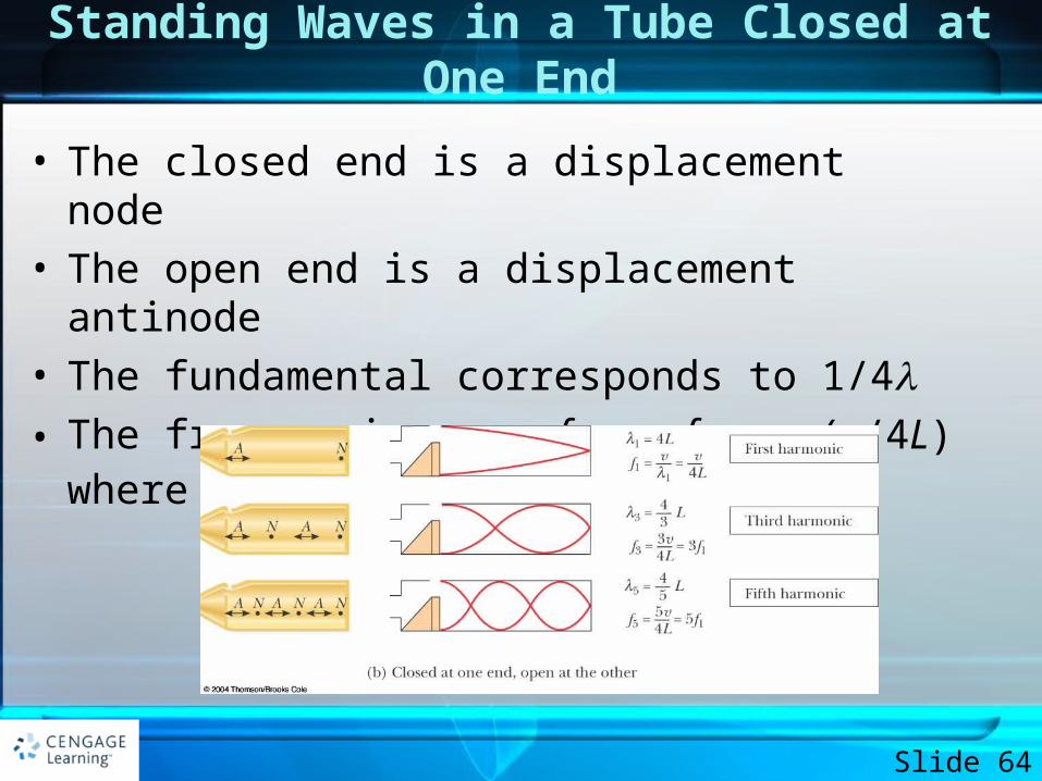
Standing Waves in a Tube Closed at One End
• The closed end is a displacement node• The open end is a displacement antinode• The fundamental corresponds to 1/4• The frequencies are ƒn = nƒ = n (v/4L) where n = 1, 3,
5, …
Slide 64
Standing Waves in Air Columns, Summary
• In a pipe open at both ends, the natural frequencies of oscillation form a harmonic series that includes all integral multiples of the fundamental frequency
• In a pipe closed at one end, the natural frequencies of oscillations form a harmonic series that includes only odd integral multiples of the fundamental frequency
Slide 65
Resonance in Air Columns, Example
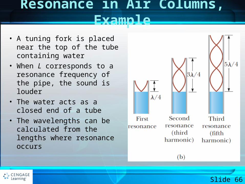
• A tuning fork is placed near the top of the tube containing water
• When L corresponds to a resonance frequency of the pipe, the sound is louder
• The water acts as a closed end of a tube
• The wavelengths can be calculated from the lengths where resonance occurs
Slide 66
EXAMPLE 14.5 Wind in a Culvert
• A section of drainage culvert 1.23 m in length makes a howling noise when the wind blows across its open ends.
Slide 67
EXAMPLE 14.5 Wind in a Culvert
• A. Determine the frequencies of the first three harmonics of the culvert if it is cylindrical in shape and open at both ends. Take v = 343 m/s as the speed of sound in air.
• B. What are the three lowest natural frequencies of the culvert if it is blocked at one end?
Slide 68
Solution - A
• The sound of the wind blowing across the end of the pipe contains many frequencies, and the culvert responds to the sound by vibrating at the natural frequencies of the air column.
Slide 69
Solution - A
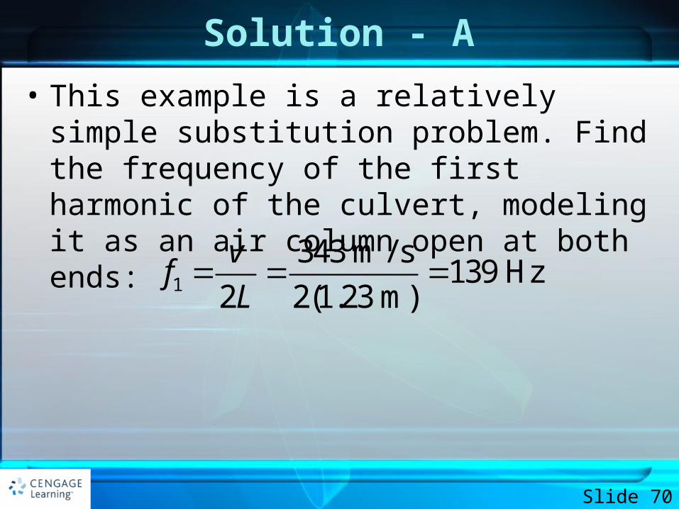
• This example is a relatively simple substitution problem. Find the frequency of the first harmonic of the culvert, modeling it as an air column open at both ends:
Slide 70
1
343 m / s139 Hz
2 2(1.23 m)
vf
L
Solution - A
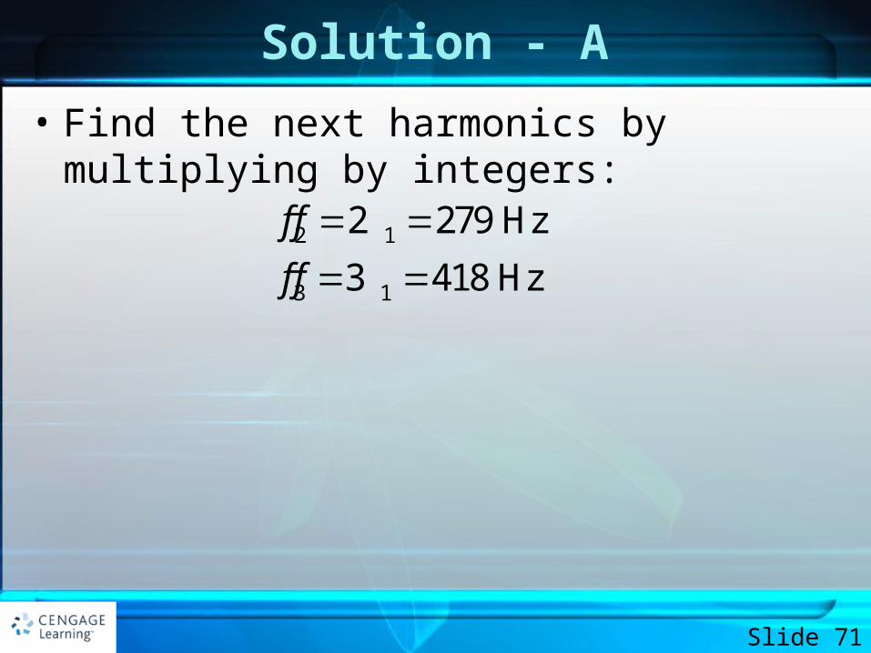
• Find the next harmonics by multiplying by integers:
Slide 71
2 1
3 1
2 279 Hz
3 418 Hz
f f
f f
Solution - B
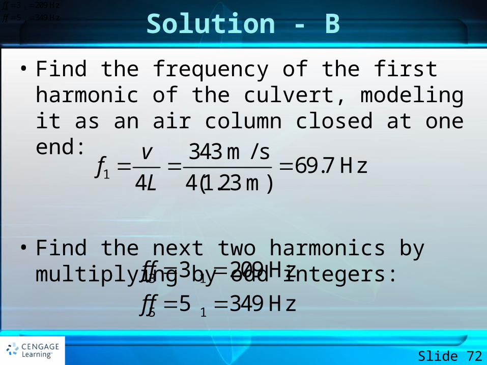
• Find the frequency of the first harmonic of the culvert, modeling it as an air column closed at one end:
• Find the next two harmonics by multiplying by odd integers:
Slide 72
1
343 m / s69.7 Hz
4 4(1.23 m)
vf
L
3 1
5 1
3 209 Hz
5 349 Hz
f f
f f
3 1
5 1
3 209 Hz
5 349 Hz
f f
f f
EXAMPLE 14.6 Measuring the Frequency of a Tuning Fork
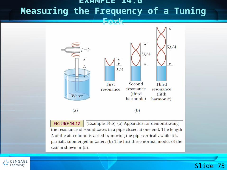
• A simple apparatus for demonstrating resonance in an air column is depicted in Figure 14.12. A vertical pipe open at both ends is partially submerged in water, and a tuning fork vibrating at an unknown frequency is placed near the top of the pipe.
Slide 73
EXAMPLE 14.6 Measuring the Frequency of a Tuning Fork
• The length L of the air column can be adjusted by moving the pipe vertically. The sound waves generated by the fork are reinforced when L corresponds to one of the resonance frequencies of the pipe. For a certain pipe, the smallest value of L for which a peak occurs in the sound intensity is 9.00 cm.
Slide 74
EXAMPLE 14.6 Measuring the Frequency of a Tuning Fork
Slide 75
EXAMPLE 14.6 Measuring the Frequency of a Tuning Fork
• A. That is the frequency of the tuning fork?
• B. What are the values of L for the next two resonance conditions?
Slide 76
Solution - A
• Consider how this problem differs from the preceding example. In the culvert, the length was fixed and the air column was p1eseItedl with a mixture of very many frequencies. The pipe in this example is presented with one single frequency from the tuning fork, and the length of the pipe is varied until resonance is achieved.
Slide 77
Solution - A
• This example is a simple substitution problem. Although the pipe is open at its lower end to allow the water to enter, the water’s surface acts like a barrier. Therefore, this setup can be modeled as an air column closed at one end.
Slide 78
Solution - A
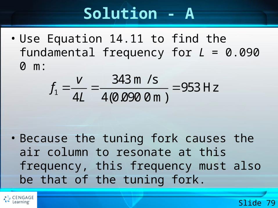
• Use Equation 14.11 to find the fundamental frequency for L = 0.090 0 m:
• Because the tuning fork causes the air column to resonate at this frequency, this frequency must also be that of the tuning fork.
Slide 79
1
343 m / s953 Hz
4 4(0.090 0 m)
vf
L
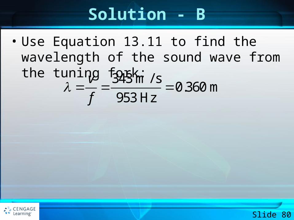
Solution - B
• Use Equation 13.11 to find the wavelength of the sound wave from the tuning fork:
Slide 80
343 m / s0.360 m
953 Hz
v
f
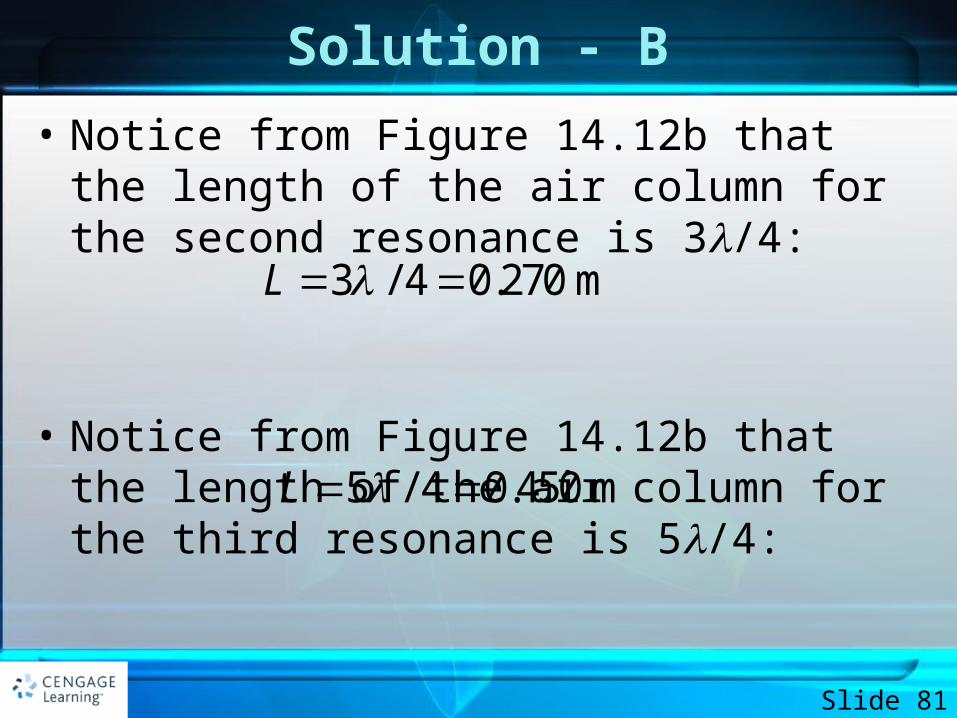
Solution - B
• Notice from Figure 14.12b that the length of the air column for the second resonance is 3/4:
• Notice from Figure 14.12b that the length of the air column for the third resonance is 5/4:
Slide 81
3 / 4 0.270 mL
5 / 4 0.450 mL
Beats
• Temporal interference will occur when the interfering waves have slightly different frequencies
• Beating is the periodic variation in amplitude at a given point due to the superposition of two waves having slightly different frequencies
Slide 82
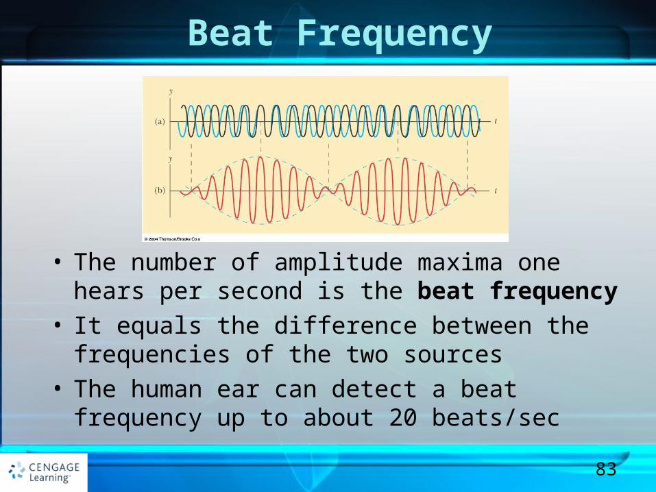
Beat Frequency
• The number of amplitude maxima one hears per second is the beat frequency
• It equals the difference between the frequencies of the two sources
• The human ear can detect a beat frequency up to about 20 beats/sec
83
Beats, Final
• The amplitude of the resultant wave varies in time according to
– Therefore, the intensity also varies in time
• The beat frequency is ƒbeat = |ƒ1 – ƒ2|
Slide 84
1 2resultant 2 cos 2
2
f fA A t
EXAMPLE 14.7 The Mistuned Piano Strings
• Two identical piano strings of length 0.750 mare each tuned exactly to 440 Hz. The tension in one of the strings is then increased by 1.0%. If they are now struck, what is the beat frequency between the fundamentals of the two strings?
Slide 85
Solution
• As the tension in one of the strings is changed, its fundamental frequency changes. Therefore, when both strings are played, they will have different frequencies and beats will be heard.
• We must combine our understanding of the waves under boundary conditions model for strings with our new knowledge of beats.
Slide 86
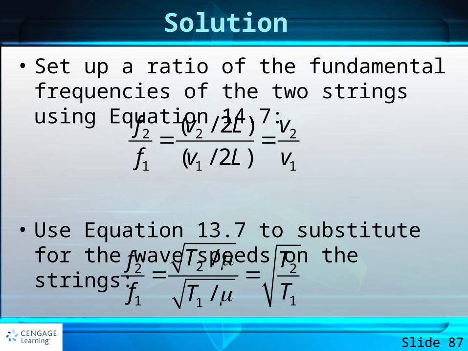
Solution
• Set up a ratio of the fundamental frequencies of the two strings using Equation 14.7:
• Use Equation 13.7 to substitute for the wave speeds on the strings:
Slide 87
2 2 2
1 1 1
( / 2 )
( / 2 )
f v L v
f v L v
22 2
1 11
/
/
Tf T
f TT
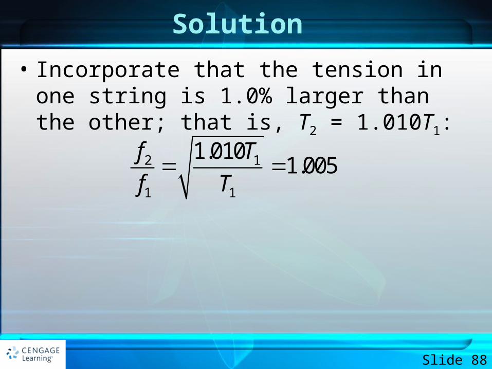
Solution
• Incorporate that the tension in one string is 1.0% larger than the other; that is, T2 = 1.010T1:
Slide 88
2 1
1 1
1.0101.005
f T
f T
Solution
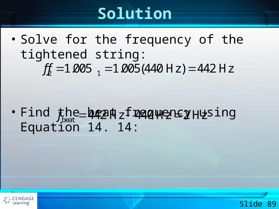
• Solve for the frequency of the tightened string:
• Find the beat frequency using Equation 14. 14:
Slide 89
2 11.005 1.005(440 Hz) 442 Hzf f
beat 442 Hz 440 Hz 2 Hzf
Solution
• Notice that a 1.0% mistuning in tension leads to an easily audible beat frequency of 2 Hz. A piano tuner can use beats to tune a stringed instrument by “beating” a note against a reference tone of known frequency. The tuner can then adjust the string tension until the frequency of the sound it emits equals the frequency of the reference tone. The tuner does so by tightening or loosening the string until the beats produced by it and the reference source become too infrequent to notice.
Slide 90
Nonsinusoidal Wave Patterns
• The wave patterns produced by a musical instrument are the result of the superposition of various harmonics
• The human perceptive response associated with the various mixtures of harmonics is the quality or timbre of the sound
• The human perceptive response to a sound that allows one to place the sound on a scale of high to low is the pitch of the sound
Slide 91
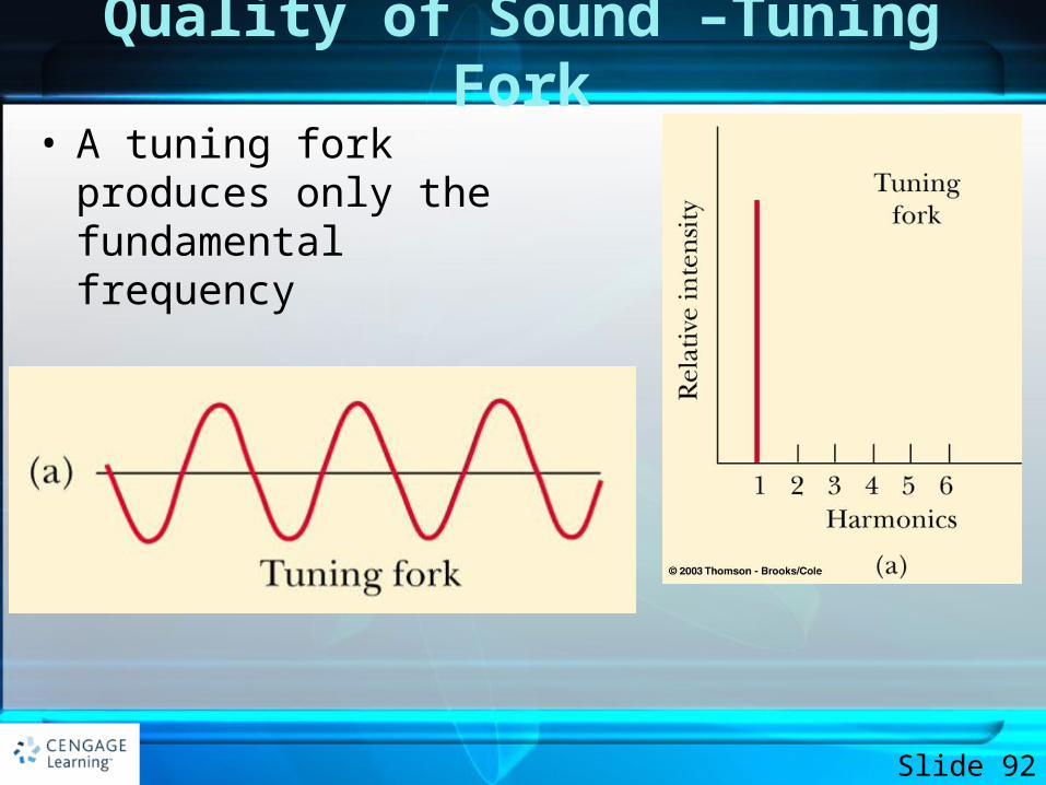
Quality of Sound –Tuning Fork
• A tuning fork produces only the fundamental frequency
Slide 92
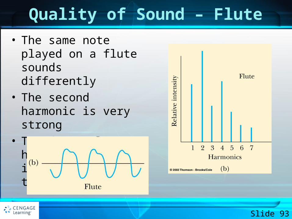
Quality of Sound – Flute
• The same note played on a flute sounds differently
• The second harmonic is very strong
• The fourth harmonic is close in strength to the first
Slide 93
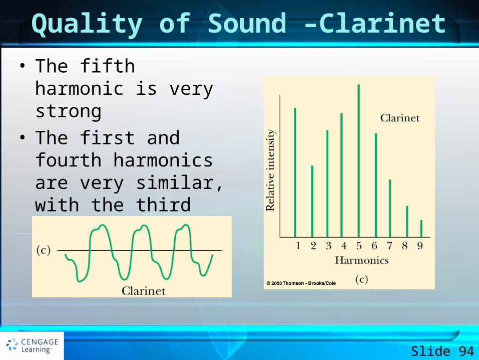
Quality of Sound –Clarinet
• The fifth harmonic is very strong
• The first and fourth harmonics are very similar, with the third being close to them
Slide 94
Analyzing Nonsinusoidal Wave Patterns
• If the wave pattern is periodic, it can be represented as closely as desired by the combination of a sufficiently large number of sinusoidal waves that form a harmonic series
• Any periodic function can be represented as a series of sine and cosine terms– This is based on a mathematical technique called Fourier’s
theorem
Slide 95
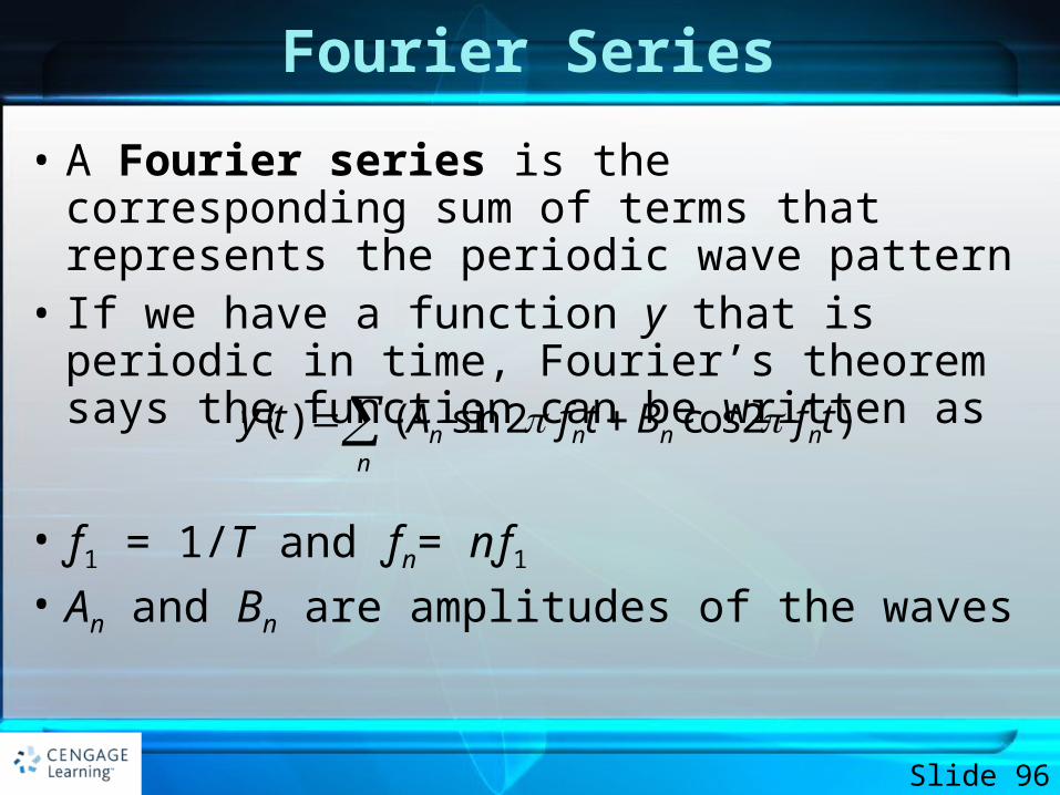
Fourier Series
• A Fourier series is the corresponding sum of terms that represents the periodic wave pattern
• If we have a function y that is periodic in time, Fourier’s theorem says the function can be written as
• ƒ1 = 1/T and ƒn= nƒ1
• An and Bn are amplitudes of the waves
Slide 96
( ) ( sin 2 cos 2 )n n n nn
y t A f t B f t
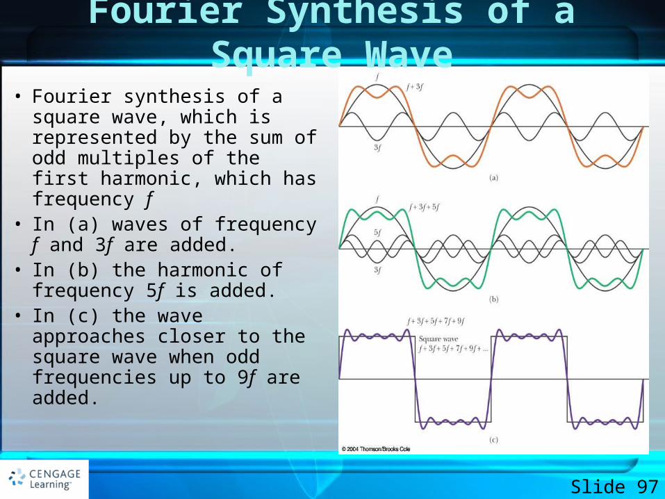
Fourier Synthesis of a Square Wave
• Fourier synthesis of a square wave, which is represented by the sum of odd multiples of the first harmonic, which has frequency f
• In (a) waves of frequency f and 3f are added.
• In (b) the harmonic of frequency 5f is added.
• In (c) the wave approaches closer to the square wave when odd frequencies up to 9f are added.
Slide 97
Standing Waves and Earthquakes• Many times cities may be built on sedimentary basins• Destruction from an earthquake can increase if the
natural frequencies of the buildings or other structures correspond to the resonant frequencies of the underlying basin
• The resonant frequencies are associated with three-dimensional standing waves, formed from the seismic waves reflecting from the boundaries of the basin
Slide 98
Exercises
• 3, 10, 12, 19, 26, 37, 40, 50, 58, 62, 70
Slide 99