centurylink mn next generation 911 psap … mn...centurylink next generation 911 psap installation...
TRANSCRIPT

CenturyLink Next Generation 911
PSAP INSTALLATION GUIDE
State of Minnesota Version: 2011.11.03

Next Generation PSAP INSTALLATION GUIDE State of Minnesota
Version Date: 2011.11.03

Disclosure
This document is authorized for public disclosure.
Intended Audience
PSAP Managers –
To get a general understanding of the Installation Migration Process
To understand when their resources are needed
To not necessarily understand the technical aspects enclosed, but to retain as a reference for Information Technology Resources
Information Technology Resources (such as CPE Vendor Technicians) –
To understand their role and need for participation
To understand the general configuration and set up.
To provide the needed ALI cabling that connects the PSAP’s ALI Controller to the “ALI MPOP” (Minimum Point of Presence that serves as a handoff between the Controller and the new Gateway equipment installed.

Version Date: 2011.11.03 Page i
Contents
1. Introduction ................................................................................................................. 3
2. Approach of Implementing MN NG911 PSAPs .......................................................... 3
2.1. PSAP Site Survey ....................................................................................................... 4
2.2. PSAP Readiness and Circuit Design .......................................................................... 4
2.3. Install Circuits and Perform Basic Install .................................................................... 4
2.4. Conduct Pre-Migration Testing .................................................................................. 5
2.5. Conduct the Migration Cutover ................................................................................... 5
2.6. Post Migration/Monitor ................................................................................................ 5
3. PSAP Facility and Equipment Requirements ............................................................. 5
3.1. Electrical and Grounding Requirements ..................................................................... 6
3.2. Cooling System Requirements ................................................................................... 6
3.3. Ownership and Insurance ........................................................................................... 7
3.4. Equipment List ............................................................................................................ 7
4. PSAP Gateway Manager Chart/Btu Output ................................................................ 7
5. Options for housing PSAP Gateway Module Equipment ............................................ 8
6. ALI Connectivity ........................................................................................................ 10
7. PSAP Preparation Requirements Pre-Migration Testing .......................................... 10
8. PSAP Preparation Requirements Migration ............................................................. 10
9. Project Contact Information ...................................................................................... 11
10. Frequently Asked Questions (FAQ) .......................................................................... 12

Version Date: 2011.11.03 Page 1
From Jackie Mines, Director Emergency Communication Networks, Minnesota Department of Public Safety:
The Division of Emergency Communication Networks, 911 Program is pleased to announce: Next Generation 9‐1‐1 service provider CenturyLink (formerly Qwest) will soon begin Phase 2 and Phase 3 to implement IP connectivity to all PSAPs in Minnesota.
This PSAP Installation Guide will serve as your tutorial as the State and CenturyLink migrate all PSAPs onto the IP network. This program includes three Phases:
1. Phase 1: Interoperability between the two legacy 911 service providers, completed September 2010.
2. Phase 2: Connect two PSAPs to the IP network, one in the CenturyLink network serving area and one in the IES network serving area. In this phase, we test our processes and procedures along with reporting and network quality.
3. Phase 3: Once Phase 2 is deemed successful, we will continue to migrate the remaining PSAPs in Minnesota. The schedule to migrate all Minnesota PSAPs (Phase 2 and Phase 3) is anticipated to start in October, 2011 and complete in July, 2013.
Note:
Your current ALI database providers will not change.
This program is intended to update the network infrastructure to IP which will prepare the state of Minnesota for Next Generation 911.
Next Generation 911 functions and features will be made available in the future when standards are finalized.
State of Minnesota IP 911 System Facts
1. Statewide IP connectivity for all PSAPS that are connected to the network. 2. Ability to transfer 9‐1‐1 calls with caller data between all PSAPs. 3. Ability to selectively route all 9‐1‐1 calls to the proper PSAP. This is limited today because
of two 9‐1‐1 service providers. 4. The statewide IP 9‐1‐1 network will provide a more robust and redundant network.
Redundancy is engineered into the network to minimize single points of failure. Diversity will be provided wherever possible.
5. Statewide IP 9‐1‐1 trouble reporting will be to one number for all PSAPs that are connected to the statewide network.
6. The statewide IP 9‐1‐1 network will support Next Generation 9‐1‐1 functionality as the features become available.
7. The statewide IP 9‐1‐1 network will allow PSAPs to share systems and applications more efficiently.
9. Alternate routing options of 9‐1‐1 calls are enhanced.

Version Date: 2011.11.03 Page 2
10. Network surveillance of the IP network is provided through one vendor and allows for reporting of all network elements on a 24x7x365 basis.
11. PSAP Involvement a. Regional meetings will be scheduled to explain expectations of the PSAP and
answer questions. b. The PSAP will need to coordinate with their CPE vendors as needed. c. Involvement in testing. d. Potential updates of MSAG may be needed. e. Access for vendors to PSAP during installation.
12. PSAP Installation a. No Legacy CPE needs to replaced, though minor upgrades may be needed to existing CPE. IP capable CPE is not a requirement to connect to the network. We will keep you informed of any Legacy CPE upgrades if required. b. On Site Survey by CenturyLink employee‐Floor Space, Grounding, UPS, and Power. c. Installation of IP gateway (also referred to as a PGM) and other equipment by CenturyLink team.
d. Your resources supporting your existing CPE (vendor or internal) will be needed to participate in the “Pre‐Migration” and “Migration” (approximately 3‐5 hours for each step and they will need to be on‐site). They will be required to re‐terminate the trunk lines and ALI cabling to the next generation system for testing and migration/cut‐over.
13. PSAP Training a. Regional information sessions to share key information and upcoming changes. b. Webinars to walk thru system monitoring tools, and reports. c. CenturyLink Team to be available for hands on training – including reports, trouble reporting, contact information.

Version Date: 2011.11.03 Page 3
11.. IINNTTRROODDUUCCTTIIOONN Welcome to the project for developing the Next Generation 911 IP Infrastructure!
The installation described in this document provides a list and description of equipment and the installation requirements to successfully deploy and implement 911 routing and ALI management services.
This project’s objective: Develop a private 911 IP network that provides IP connectivity to all Minnesota PSAPs.
In essence, the project is laying down the infrastructure and IP connectivity to enable Next Generation 911 applications. These applications are down the road and will require extensive planning. Those efforts will be addressed in separate projects and are not within this project’s scope.
For this project, the goal is to implement the Next Generation 911 IP infrastructure with limited disturbance of current PSAP operations. The migration to IP should be transparent to your PSAP.
22.. AAPPPPRROOAACCHH OOFF IIMMPPLLEEMMEENNTTIINNGG MMNN NNGG991111 PPSSAAPPSS CenturyLink, with its vendor partners, employ an implementation methodology following the steps outlined below.

Version Date: 2011.11.03 Page 4
22..11.. PPSSAAPP SSIITTEE SSUURRVVEEYY
The first step in the PSAP installation process is the PSAP site survey. A CenturyLink representative will schedule an appointment with each PSAP to assess the PSAP facilities and determine if additional space, equipment, power, or HVAC is required. The representative will interview and document current facility information to accumulate as much information as possible in order to provide for a smooth installation. The site survey includes the following categories:
General administrative information 911 PSAP equipment inventory Administrative telephone Information Equipment delivery Physical Site Survey (Equipment Placement)
o Equipment Cabinet Location o Electrical and Grounding o Environmental Evaluation
911 Trunk List CPE Programmed Transfer List (two or three digit star codes) Use of Trunk Voice Logger (will also need to be migrated when migrating 911
trunks)
22..22.. PPSSAAPP RREEAADDIINNEESSSS AANNDD CCIIRRCCUUIITT DDEESSIIGGNN
With information obtained from the Survey, the CenturyLink Team will begin the PSAP Readiness and Circuit Design phase.
For PSAP Readiness, you will be working with either the Survey team or a Project Manager in walking through the items to be in place before the equipment can be installed at the PSAP site.
Example PSAP Readiness items include having the proper space, electrical, grounding, and humidity requirements (outlined in a later section of this guide). For Circuit Design, the CenturyLink Team will be reviewing the information from the survey to design the appropriate circuits for connecting your PSAP to the Next Generation 911 network.
22..33.. IINNSSTTAALLLL CCIIRRCCUUIITTSS AANNDD PPEERRFFOORRMM BBAASSIICC IINNSSTTAALLLL
The circuit and basic installation of the equipment occurs next with the circuits needing to be installed first. Note: Circuit technicians may not always understand what the circuits being installed are for when they arrive to perform their needed piece of making the connections at your site. At CenturyLink, we will do what we can to give you as much advanced notification as possible.
Once circuits are connected, the Equipment Install Team will arrive at your PSAP to perform the basic equipment install process. This process can take up to three (3) days typically beginning on a Tuesday with the Install Team needing access to the PSAP during that time. There may be some rudimentary connection required from the PSAP controller to the PGM during the last day. If needed, we will work with you to coordinate a visit with your supporting CPE Vendor Technician for the install.

Version Date: 2011.11.03 Page 5
This installation, once completed, will not be connected to your PSAP equipment; it will sit as a stand-alone, though remote testing will be continually conducted.
At this time, specifications will be determined for connecting the ALI circuits that will require coordination with your CPE vendor technician to build the ALI cables that will connect at a designated connection point specified by the Equipment Installation technicians.
22..44.. CCOONNDDUUCCTT PPRREE--MMIIGGRRAATTIIOONN TTEESSTTIINNGG VVOOIICCEE NNEETTWWOORRKK,, AALLII MMIIGGRRAATTIIOONN
Approximately two (2) weeks before migration, Pre-Migration Testing of the Voice portion of the network will be conducted, requiring at least one PSAP resource along with your supporting CPE technician (possibly a vendor if not self-supported). This test will be conducted during normal business hours and will require a trunk connection (Refer to section 7 for turn up of the trunk connection for the pre-migration testing). The test should take two to four hours.
In addition to the Pre-Migration of the Voice portion, the ALI portion will be migrated.
22..55.. CCOONNDDUUCCTT TTHHEE VVOOIICCEE NNEETTWWOORRKK MMIIGGRRAATTIIOONN CCUUTTOOVVEERR Approximately two weeks after successful completion of Pre-Migration Voice Network testing, the Team will be proceed to conduct the Migration. This deployment will be conducted during the maintenance window beginning at 3AM, requiring your attendance along with your supporting CPE Vendor technician. The Migration process should not take longer than four (4) hours. Note: If testing fails or if the migration is not working as expected, the PSAP will revert back to the legacy CAMA trunks and migration will be rescheduled.
22..66.. PPOOSSTT MMIIGGRRAATTIIOONN//MMOONNIITTOORR CenturyLink will monitor and continually communicate with you on Post Migration status. After thirty calendar days in which no significant issues are experienced, CenturyLink will request your acceptance of the installation. The CenturyLink team will be prepared to address and troubleshoot events, should they surface; contact CenturyLink 911 Repair at 1-800-357-0911. Should unexpected events of high severity occur before the completion of the acceptance period, it will be possible to re-connect to the previous legacy environment.
33.. PPSSAAPP FFAACCIILLIITTYY AANNDD EEQQUUIIPPMMEENNTT RREEQQUUIIRREEMMEENNTTSS CenturyLink and Intrado are partners in the effort to upgrade your PSAP to the Next Generation IP Network. Intrado technicians will lead the installation effort for the equipment required.
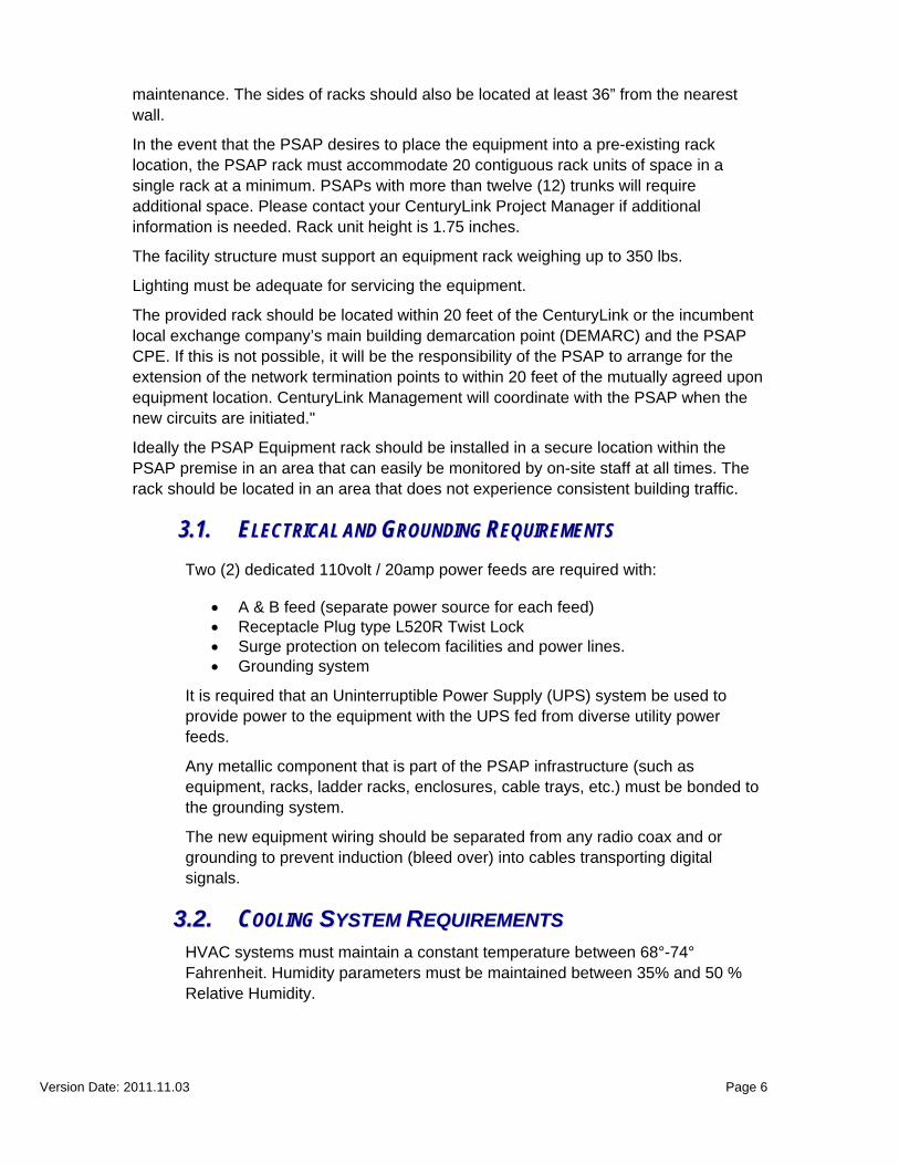
The new PSAP Equipment is installed in 20 Rack Units of one standard data center 19” equipment rack. It requires approximately 24” X 108” of floor space. These dimensions enable the 35” of space in front and behind the rack, which is required for proper airflow and to enable a technician the adequate space to perform equipment installations and
Version Date: 2011.11.03 Page 6
maintenance. The sides of racks should also be located at least 36” from the nearest wall.
In the event that the PSAP desires to place the equipment into a pre-existing rack location, the PSAP rack must accommodate 20 contiguous rack units of space in a single rack at a minimum. PSAPs with more than twelve (12) trunks will require additional space. Please contact your CenturyLink Project Manager if additional information is needed. Rack unit height is 1.75 inches.
The facility structure must support an equipment rack weighing up to 350 lbs.
Lighting must be adequate for servicing the equipment.
The provided rack should be located within 20 feet of the CenturyLink or the incumbent local exchange company’s main building demarcation point (DEMARC) and the PSAP CPE. If this is not possible, it will be the responsibility of the PSAP to arrange for the extension of the network termination points to within 20 feet of the mutually agreed upon equipment location. CenturyLink Management will coordinate with the PSAP when the new circuits are initiated."
Ideally the PSAP Equipment rack should be installed in a secure location within the PSAP premise in an area that can easily be monitored by on-site staff at all times. The rack should be located in an area that does not experience consistent building traffic.
33..11.. EELLEECCTTRRIICCAALL AANNDD GGRROOUUNNDDIINNGG RREEQQUUIIRREEMMEENNTTSS
Two (2) dedicated 110volt / 20amp power feeds are required with:
A & B feed (separate power source for each feed) Receptacle Plug type L520R Twist Lock Surge protection on telecom facilities and power lines. Grounding system
It is required that an Uninterruptible Power Supply (UPS) system be used to provide power to the equipment with the UPS fed from diverse utility power feeds.
Any metallic component that is part of the PSAP infrastructure (such as equipment, racks, ladder racks, enclosures, cable trays, etc.) must be bonded to the grounding system.
The new equipment wiring should be separated from any radio coax and or grounding to prevent induction (bleed over) into cables transporting digital signals.
33..22.. CCOOOOLLIINNGG SSYYSSTTEEMM RREEQQUUIIRREEMMEENNTTSS HVAC systems must maintain a constant temperature between 68°-74° Fahrenheit. Humidity parameters must be maintained between 35% and 50 % Relative Humidity.

Version Date: 2011.11.03 Page 7
33..33.. OOWWNNEERRSSHHIIPP AANNDD IINNSSUURRAANNCCEE CenturyLink will maintain ownership of all PGM equipment at the PSAP. CenturyLink may, at its discretion, remove, replace, or upgrade the equipment as reasonably necessary to provide successful 911 services. CenturyLink will provide insurance for all PGM Equipment.
33..44.. EEQQUUIIPPMMEENNTT LLIISSTT The following list identifies the typical equipment provided by CenturyLink required for a PSAP installation: Great Lakes Cabinet (Model Number GL 780 ES) MPOP (1) [Minimum Point of Presence – essentially a cabling meet point
for connecting the ALI Controller to the PGM PSAP Gateway Manager (PGM) (Minimum of 2 based on number of 911
Trunks – see chart in section 10.) Patch Panel (1) Console Server (Term Server) (2) Cisco 2821 Router or equivalent (2)
44.. PPSSAAPP GGAATTEEWWAAYY MMAANNAAGGEERR CCHHAARRTT//BBTTUU OOUUTTPPUUTT
# of Trunks
BTU/HR
2 – 12 2,500
13 – 24 2,800
25 – 40 3,100
41 – 50 3,400
51 – 60 3,700
61 – 70 4,000
71 – 80 4,300
81 – 90 4,600

Version Date: 2011.11.03 Page 8
55.. OOPPTTIIOONNSS FFOORR HHOOUUSSIINNGG PPSSAAPP GGAATTEEWWAAYY MMOODDUULLEE EEQQUUIIPPMMEENNTT PSAPs have options for housing the PSAP Gateway Module Equipment
5.1. Cabinet – Standard or shorter
5.2. 4 Post Rack – Either furnished or use of Existing
5.3. Wall Mount – Either furnished or use of Existing
Standard installation (Cabinet Option) includes a Great Lakes Cabinet pictured below. A CenturyLink Technician will conduct a site survey to help determine location of the cabinet (or the choice of Rack or Wall Mount) within the PSAP equipment room (or the choice of Rack or Wall Mount)
The cabinet is offered in two (2) different sizes.
1. 24.0” Width, 32.0” Depth and 72.0” Height (Pictured below)
2. 24.0” Width, 32.0” Depth and 48.0” Height (Shorter version of Cabinet pictured below)
Figure 1: PSAP Equipment Cabinet

Version Date: 2011.11.03 Page 9
I O50/60 Hz
100-240V
12 V 18A
OPTIONAL RPS INPUT
Do Not Remove During Netw ork Op eratio n
COMPACT FLASH
S YSPWR
AUX/PWR
SYSACT CF
1
0
C ON SOLE
AU X
Cisco 2800 SERIES
-48V 8A
I P
I O50/60 Hz
100-240V
12 V 18A
OPTIONAL RPS INPUT
Do Not Remove During Netw ork Op eratio n
COMPACT FLASH
S YSPWR
AUX/PWR
SYSACT CF
1
0
C ON SOLE
AU X
Cisco 2800 SERIES
-48V 8A
I P
7 8 9 10 11 12 13 14 15 16 17 18 19 20 21 22 23 241 2 3 4 5 6
F11/E/1
1
2
3
4
5
6
7
8
1 2 3 4 5 6 7 81 2 3 4 5 6 7 8
MONO UT
IN
www.t elec t. comw ww .telect.com
T
R
T
R
SG
OUT
IN
1
PV DM2 PV DM1 A IM1 AI M0
A
F
S
L
A
F
S
L
A=ACT
S=SPEED
GE 0 /1 GE 0/0
F=FDX
L=LINK
PV DM0
EVM 2 ONLY
-4 8V GE
Ex tPw r
10/10 0/1000Base -Tx
E N
FastEthernet Ports15 x
7x 0x
8x
15x 7x 14 x 6x 13 x 5x 12 x 4x 11x 3x 10 x 2x 9x 1x 8x 0x
NM16E SW -PW R
T1 DSU/CSU
LO OPBACK
LP A L CD
S EE MANUALB EF OREINSTALLATION W IC
1 DS UT1
DO NOT INSTALL WAN INTERFACECARDS WITH POWER APPLIED
DO NOT INSTALL WAN INTERFACECARDS WITH POWER APPLIED
DO NOT INSTALL WAN INTERFACECARDS WITH POWER APPLIED
1
PV DM2 PV DM1 A IM1 AI M0
A
F
S
L
A
F
S
L
A=AC T
S=SPEED
GE 0 /1 GE 0/0
F=FD X
L=LIN K
PV DM0
EVM 2 ONLY
-4 8V GE
Ex tPw r
10/10 0/1000Base -Tx
E N
FastEthernet Ports15 x
7x 0x
8x
15x 7x 14 x 6x 13 x 5x 12 x 4x 11x 3x 10 x 2x 9x 1x 8x 0x
NM16E SW -PW R
T1 DSU/CSU
LO OPBACK
LP AL CD
SEE MANUALBEF OREINSTALLATION W IC
1 DSUT1
DO NOT INSTALL WAN INTERFACECARDS WITH POWER APPLIED
DO NOT INSTALL WAN INTERFACECARDS WITH POWER APPLIED
DO NOT INSTALL WAN INTERFACECARDS WITH POWER APPLIED
1357
2468
Figure 2: PSAP Equipment Cabinet Elevation Drawing including Equipment

Version Date: 2011.11.03 Page 10
66.. AALLII CCOONNNNEECCTTIIVVIITTYY As part of the implementation, ALI connectivity will use the new IP network. In order to transition to the IP Network, two (2) new ALI cables are required for connectivity between the ANI/ALI Controller and the ”ALI MPOPs” – the ALI jacks mounted by the Next Gen equipment Install team, labeled ALI 1 and ALI 2. The ALI conversion to the new network occurs shortly before the Voice Network Pre-Migration.
The CPE technician for the PSAP is responsible for building the cable and connecting the ALI Controller to the designated ALI MPOP jacks. Whether CenturyLink, self, or Vendor supported; each PSAP technical team must make two ALI cables prior to Pre-migration.
The ALI migration provides an excellent opportunity to increase the baud rate to 9600, which may provide a lift in ALI display speed as well as establish a consistent rate among all MN PSAPs. Note: the current legacy modems will no longer be used, though a baud rate needs to be set in order to establish synchronization between the legacy CPE and the ALI system using the IP network.
77.. PPSSAAPP PPRREEPPAARRAATTIIOONN RREEQQUUIIRREEMMEENNTTSS PPRREE--MMIIGGRRAATTIIOONN VVOOIICCEE
TTEESSTTIINNGG AANNDD AALLII MMIIGGRRAATTIIOONN Preparation requirements for PSAP readiness for Pre-migration testing:
1. Complete Positron Lifeline 100 Chip Set upgrade (if applicable to PSAP CPE). 2. Provide PSAP resources: one person to make test calls and one person to receive
calls and make transfers at a PSAP position available for testing. Pre-migration testing is typically from 9:00 am to noon local time on either Mondays or Wednesdays. Retests, if needed, are typically one (1) hour on Fridays.
3. The PSAP resource at the position can be the CPE Vendor resource, who in addition to testing the receiving and transferring of calls, will also perform the duties of “lift and lay” of the test trunk – moving one live CAMA trunk from the legacy system to the NextGen System (note: provision will be made at time of testing to prevent live traffic on the test trunk as well as transferring a live call to an administrative line should all other trunks be busy during the time of testing.)
4. The PSAP resource initiating test 911 calls must have a standard phone line with a known ten digit phone number and not a line from a PBX. A fax line or CPE test modem line can be used.
5. PSAP resources receiving test calls will be asked about the quality of the call e.g. the volume is at the appropriate level and if there is echo experienced on the line.
6. Document the phone number at the start of the testing as you will be asked by the Test Lead.
7. The physical location of the phone making the test 911 calls will need to be at a far enough distance from the person receiving the call from the PSAP position. This will remove the possibility of unnecessary echo as part of the testing is to assess call quality.
8. The Method of Procedure (MOP) supplied by CenturyLink must be printed and reviewed to be prepared for the physical transfer of the trunk. If any pre-wiring needs to be completed ahead of time, it will make testing go more quickly.
9. ALI cables prepared for the ALI Migration.
88.. PPSSAAPP PPRREEPPAARRAATTIIOONN RREEQQUUIIRREEMMEENNTTSS VVOOIICCEE MMIIGGRRAATTIIOONN Preparation requirements for PSAP readiness for Migration:

Version Date: 2011.11.03 Page 11
1. Migration essentially will follow the steps of Pre-Migration, though in exhaustive
detail for each step as the PSAP will then be fully cutover to the NextGen system.
2. Provide PSAP resources: one person to make test calls and one person to receive calls. Migrations are typically from 3:00 to 8:00 am local time on either Tuesday or Thursday’ but sometimes on Wednesday. A calendar invitation will be sent via email.
3. As in Pre-Migration, the PSAP resource at the position can be the CPE Vendor resource, who in addition to testing the receiving and transferring of calls, will also perform the duties of “lift and lay” of the trunks and the ALI connections.
4. As in Pre-Migration, PSAP resources receiving test calls will be asked about the quality of the call e.g. the volume is at the appropriate level and if there is echo experienced on the line.
5. The MOP (sent via email) must be printed and reviewed to be ready for transferring the trunks to the PGM. If any pre-wiring needs to be done ahead of time, it will make the Migration go more quickly.
99.. PPRROOJJEECCTT CCOONNTTAACCTT IINNFFOORRMMAATTIIOONN
Contact Name
Organization Project Role Title Telephone Email Address
Cathy Vacinek CenturyLink
Project Manager PSAP Operational Readiness,
Installation, Provisioning, Migration
Project Manager 612-336-3104 [email protected]
Larry Hegle Enterprise
Visions Surveying of PSAPs, Operational
Readiness Checklist Principal 651-556-2030 [email protected]
Jake Jacobson CenturyLink Program Manager MN NG911
Program Manager
612-664-4088 (o) 612 384 6511 (c)
Jerry Christians
Mission Critical Partners
ECN/MN DPS Next Gen Project Manager
Senior Technology Specialist
715-644-8062 [email protected]
Paul Mraz Independent Emergency
Services (IES) IES Point of Contact
Network Engineer
320-234-5241 [email protected]
Note: After PSAP migration to the NextGen Network, if you encounter an issue where you believe the equipment, circuits, and/or network are not working as expected, please contact CenturyLink 911 Repair at 1-800-357-0911. They will engage CenturyLink to resolve the issue.

Version Date: 2011.11.03 Page 12
1100.. FFRREEQQUUEENNTTLLYY AASSKKEEDD QQUUEESSTTIIOONNSS ((FFAAQQ)) 1. Do the circuits ordered provide diversity? The network is designed with enough
capacity so that either T1 or multiple bonded T1s (depending on the number of PSAP trunks) can support all of the PSAP trunks should one T1 be out of service. In an IP environment, you can lose a single T1 and still be at full trunk capacity. PGMs are not tied to any one circuit.
2. What if a PGM fails? In a typical PGM environment two (2) PGMs are installed and configured so that only the odd ports are active on PGM 1 and the even ports on PGM2. In the event of a PGM outage, a technician will physically move the trunk connections from the failed PGM to the working PGM, which will handle all traffic.
3. Will the PSAP experience down time during the installation? No, the installation does not affect your live 911 environment.
4. When does the PSAP receive the equipment and the equipment cabinet? The equipment including cabinet will arrive with the technicians performing the installation.
5. How long will the installation take? The installation will typically take 2 days to complete.
6. Do circuits need to be installed at the PSAP prior to equipment installation? Yes at least one (1) circuit should be in place prior to installation of the equipment. CenturyLink will implement the turn-up of the necessary T1 circuits, coordinating with the Local Exchange Carrier where needed. Having a circuit in place allows the installation technician to do following:
a. Testing/Verification of communication between the PSAP equipment and the IP Selective Router.
b. Verification of equipment configurations c. Verification that cabling is correct (all cables plugged into correct ports etc.) d. Verification of signaling (for example, use of test calls to a butt set is used at
PSAP installs)
7. Who provides the PSAP specific Circuit turn-up, Equipment Installation, and Migration schedule? The CenturyLink Project Manager listed in Section 9.
8. Who tests the new equipment in a live situation? The CenturyLink Project Manager will coordinate with the PSAP to test the Next Gen Network and new equipment using a PSAP-provided test trunk about one or two weeks prior to migration. This pre-migration testing will include, but is not be limited to, the following scenarios:
911 test calls 1-button transfers. 3 digit * code transfers. Overflow for PSAP when trunks are traffic busy. Overflow for PSAP when they have to abandon. Test transfers to other PSAPs on NextGen Network. Test transfers to other PSAPs (including back-up or night PSAPs) on Legacy
Network. TDD Abandoned Calls

Version Date: 2011.11.03 Page 13
10. Who provides the PSAP specific Circuit turn-up, Equipment Installation, and Migration schedule?
The CenturyLink Project Manager listed in the Project Contact Information Section.
11. If there is a problem with the equipment, circuits, and/or network, who should be contacted?
Before PSAP migration to NextGen Network, contact the CenturyLink Project Manager listed in the Project Contact Information Section.
. After PSAP migration, contact CenturyLink 911 Repair at 1-800-357-0911.
12. Does the PSAP need to provide E&M signaling on the new E911 trunks to the PSAP PBX? The PSAP will need to provide the same type of trunk and same type of signaling that is provided to the existing E911 Network.

Version Date: 2011.11.03 Page 14
AAPPPPEENNDDIIXX AA:: NNEETTWWOORRKK DDRRAAWWIINNGG ---- WWHHAATT IISS CCHHAANNGGIINNGG

Version Date: 2011.11.03 Page 15
AAPPPPEENNDDIIXX AA:: NNEETTWWOORRKK DDRRAAWWIINNGG MMOORREE DDEETTAAIILL
CenturyLink MPLS IQ
Network C
PSAP
PSAP Gateway Modules
POP
CORE NETWORK PSAP CONNECTLEGACY CONNECT
POP
POP
IPT1(s)
100Mbps EoSONET connection
100Mbps EoSONET connection
Century Link MPLS IQNetwork A
CenturyLink MPLS IQNetwork B
IP Selective Router
Legacy Network Gateway
(LNG)
DUAL100Mbps
Connections To the IP SRs
Primary POP
Secondary POP
Primary POP
Secondary POP
Diverse DUAL DS3Connections to the LNGs
Intrado IEN ALI/
DMS
Intrado IEN ALI/
DMS
IES IEN ALI/DMS
IES IEN ALI/DMS
IP Selective Router
Legacy SRs
End officesServed by existing IOF network
End officesServed by existing IOF network
CML
CML
CML ILEC SWITCH
ILEC SWITCH
ILEC SWITCHChannelized
DS1s
POP
DUALTANDEMS
Legacy Network Gateway
(LNG)

Version Date: 2011.11.03 Page 16
AAPPPPEENNDDIIXX BB:: PPSSAAPP CCHHEECCKKLLIISSTT FFOORR IINNSSTTAALLLLAATTIIOONN RREEAADDIINNEESSSS
Environment
# Item Description Installation Guide
Reference
Date Completed
E-1 Lighting Sufficient lighting must be available in equipment area. Lighting should not be obstructed.
3. PSAP Facility and Equipment Requirements
E-2 Room Temp and Humidity
Ambient temperature and relative humidity in the E911 equipment area should be maintained between 68 to 74 degrees Fahrenheit. Relative humidity should be between 35 to 50 percent, non-condensing.
3.2 Cooling System Requirements, and General Practice
E-3 Ventilation & Air Filtration
Ventilation & Air Filtration requirements should be appropriate if temperature & humidity requirements are met. Local (City, County, State) Code & Standards must be adhered to.
4 PSAP Gateway Manager Chart/BTU output
E-4 Fire Safety The equipment area should have adequate fire detection. Local (City, County, State) Code Fire Safety & Standards must be adhered to.
General Practice
E-5 Water /Flood Management
If equipment is placed in a basement, all penetrations into the basement from outside the building should be properly sealed. It is also preferable in a basement installation that sump pumps and/or drains be present.
General Practice
Power
# Item Description Installation Guide
Reference
Date Completed

Version Date: 2011.11.03 Page 17
P-1 AC Power
Dedicated AC power must be available and appropriate power source available to support the product being purchased. The AC power boxes should be labeled with designation name, amperage number, voltage, and type of service.
3.1 Electrical And Grounding Requirements
P-2 Electrical Grounding
Specification: Two dedicated 110volt/20amp UPS circuits are required with: 1) A & B feed (separate power source) and 2) L5-20R twist lock receptacles. The cabinet ground must be bonded to the grounding system.
3.1 Electrical And Grounding Requirements
P-3 UPS AC Power should be backed up by a generator and equipment should be protected by UPS with spike prevention.
3.1 Electrical And Grounding Requirements
P-4 Non-UPS access Non-UPS power should be available at or near the cabinet (for future testing/troubleshooting needs)
3.1 Electrical And Grounding Requirements
Grounding
# Information Required
Notes/Description Installation Guide
Reference
Date Completed
G-1 Telecommunications Ground Collection Point
Proper ground bar access in place (This is not provided by Next Gen Install Team)
3.1 Electrical And Grounding Requirements

Version Date: 2011.11.03 Page 18
G-2
The Single Point Ground System (SPGS) is a grounding philosophy that requires all major components of the Building Safety Protection System to be designed and bonded to a single ground reference point.
The Main Buss bar can be wall mounted and #6 (MAX 25') ran to the rack, cabinet etc. with a dedicated ground wire to the main panel electrical ground. A Cold Water Pipe (CWP) is not acceptable. The customer should contact an electrician for this work if needed.
3.1 Electrical And Grounding Requirements

Version Date: 2011.11.03 Page 19
PSAP Gateway Manager Location
# Item Description Installation
Guide Reference
Date Completed
GL-1 Equipment Area
The space should also be large enough to accommodate anticipated growth. Ceiling should be at least 8’0” from floor. PC workstations and servers should be stored in location where they are clear from foot traffic and/or accidental kicking.
3. PSAP Facility and Equipment Requirements
GL-2 Cabinet Location:
If using PGM Cabinet -- dimensions a 24" W x 32" D x 72" H. Their must be room in front and back to open the cabinet doors.
3. PSAP Facility and Equipment Requirements
GL-3 If not using Cabinet, Rack Location:
Gateway can be installed in 20 Rack Units of one standard data center 19” equipment rack. It will require 24” X 108” of floor space. These dimensions enable the 35” of space in front and behind the rack, which is required for proper airflow and to enable a technician adequate space to perform equipment installations and maintenance. The sides of racks should also be located at least 36” from the nearest wall.
3. PSAP Facility and Equipment Requirements
GL-4 Wire Pathway Need wire pathway above or below the selected PGM Cabinet location
General Practice
GL-5 Physical Security
Is the cabinet installation location secure? Please describe security arrangements.
General Practice
Version Date: 2011.11.03 Page 20
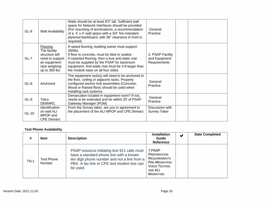
GL-6 Wall Availability
Walls should be at least 8’0” tall. Sufficient wall space for Network Interfaces should be provided (For mounting of terminations, a recommendation of a 4’ x 4’ wall space with a 3/4” fire-retardant plywood backboard, with 36” clearance in front is required).
General Practice
GL-7
Flooring The facility structure will need to support an equipment rack weighing up to 350 lbs.
If raised flooring, building owner must support 350lbs. If floor is concrete, must be tiled or sealed. If carpeted flooring, then a true anti-static mat must be supplied by the PSAP for backroom equipment. Anti-static mat must be 3 ft larger than the module base on all four sides.
3. PSAP Facility and Equipment Requirements
GL-8 Anchored
The equipment rack(s) will need to be anchored to the floor, ceiling or adjacent racks. Properly configured anchor bolt assemblies (Concrete, Wood or Raised floor) should be used when installing rack systems.
General Practice
GL-9 Telco DEMARC
Demarcation located in equipment room? If not, needs to be extended and be within 20' of PSAP Gateway Manager (PGM)
General Practice
GL-10
Identification on wall ALI MPOP and CPE Demarc
From the Survey taker, are you in agreement to the placement of the ALI MPOP and CPE Demarc
Discussion with Survey Taker
Test Phone Availability
# Item Description Installation
Guide Reference
Date Completed
TN-1 Test Phone Number
PSAP resource initiating test 911 calls must have a standard phone line with a known ten digit phone number and not a line from a PBX. A fax line or CPE test modem line can be used.
77..PPSSAAPP
PPRREEPPAARRAATTIIOONN
RREEQQUUIIRREEMMEENNTTSS
PPRREE--MMIIGGRRAATTIIOONN
VVOOIICCEE TTEESSTTIINNGG
AANNDD AALLII MMIIGGRRAATTIIOONN

Version Date: 2011.11.03 Page 21
AAPPPPEENNDDIIXX CC:: IIPP PPSSAAPP NNEETTWWOORRKK CCOONNNNEECCTTIIVVIITTYY DDIIAAGGRRAAMM AANNDD CCOORRRREESSPPOONNDDIINNGG PPIICCTTUURREESS

Version Date: 2011.11.03 Page 22

Version Date: 2011.11.03 Page 23
AAPPPPEENNDDIIXX DD:: PPSSAAPP GGAATTEEWWAAYY EEQQUUIIPPMMEENNTT
I O50/60 Hz
100-240V
12V 18A
OPTIONAL RPS INPUT
Do Not Remove During Netw ork Operation
COMPACT FLASH
SYSPW R
AUX/PW R
SYSACT CF
1
0
C ON SOLE
AU X
Cisco 2800 SERIES
-48V 8A
IP
I O50/60 Hz
100-240V
12V 18A
OPTIONAL RPS INPUT
Do Not Remove During Netw ork Operation
COMPACT FLASH
SYSPW R
AUX/PW R
SYSACT CF
1
0
C ON SOLE
AU X
Cisco 2800 SERIES
-48V 8A
IP
7 8 9 10 11 12 13 14 15 16 17 18 19 20 21 22 23 241 2 3 4 5 6
F11/E/1
1
2
3
4
5
6
7
8
1 2 3 4 5 6 7 81 2 3 4 5 6 7 8
M ONOUT
IN
www.telect.comwww.telec t.c om
T
R
T
R
SG
OUT
IN
1
PVDM2 PVDM1 AIM1 AI M0
A
F
S
L
A
F
S
L
A=ACTS=SPEED
GE 0/1 GE 0/0
F=FDXL=LIN K
PVDM0
EVM 2 ONLY
-48V GE
Ex tPwr
10/100/1000Bas e-Tx
E N
FastEthernet Ports15x
7x 0x
8x
15x 7x 14x 6x 13x 5x 12x 4x 11x 3x 10x 2x 9x 1x 8x 0x
NM16E SW-P WR
T1 DSU/CSU
LO O PBACK
LP AL CD
SEE MANUALBEFOREINSTALLATION WIC
1 DSUT1
DO NOT INSTALL WAN INTERFACECARDS WITH POWER APPLIED
DO NOT INSTALL WAN INTERFACECARDS WITH POWER APPLIED
DO NOT INSTALL WAN INTERFACECARDS WITH POWER APPLIED
1
PVDM2 PVDM1 AIM1 AI M0
A
F
S
L
A
F
S
L
A=ACT
S=SPEED
GE 0/1 GE 0/0
F=FDX
L=LIN K
PVDM0
EVM 2 ONLY
-48V GE
Ex tPwr
10/100/1000Bas e-Tx
E N
FastEthernet Ports15x
7x 0x
8x
15x 7x 14x 6x 13x 5x 12x 4x 11x 3x 10x 2x 9x 1x 8x 0x
NM16E SW-P WR
T1 DSU/CSU
LOO PB ACK
LP AL CD
SEE MANUALB EFOREINSTALLATION WIC
1 DS UT1
DO NOT INSTALL WAN INTERFACECARDS WITH POWER APPLIED
DO NOT INSTALL WAN INTERFACECARDS WITH POWER APPLIED
DO NOT INSTALL WAN INTERFACECARDS WITH POWER APPLIED
1357
2468

Version Date: 2011.11.03 Page 24
AAPPPPEENNDDIIXX EE:: TTYYPPIICCAALL PPSSAAPP GGAATTEEWWAAYY MMAANNAAGGEERR PPOORRTT AASSSSIIGGNNMMEENNTTSS
7 8 9 10 11 12 13 14 15 16 17 18 19 20 21 22 23 241 2 3 4 5 6
F11/E/1

Version Date: 2011.11.03 Page 25
AAPPPPEENNDDIIXX FF:: AALLII CCOONNNNEECCTTIIVVIITTYY TTOO TTHHEE EEXXIISSTTIINNGG AANNII//AALLII CCOONNTTRROOLLLLEERR
I O50/60 Hz
100-240V
12V 18A
OPTIONAL RPS INPUT
Do Not Remove During Netw ork Operation
COMPACT FLASH
SYSPWR
AUX/PWR
SYSACT CF
1
0
CONSOLE
AUX
Cisco 2800 SERIES
-48V 8A
IP

Version Date: 2011.11.03 Page 26
AAPPPPEENNDDIIXX GG:: AALLII MMIIGGRRAATTIIOONN MMEETTHHOODD OOFF PPRROOCCEEDDUURREE ((MMOOPP))
Task
Number
Task Group Working the Step
Individual’s Name
Estimated Time
1 Confirm communication between the PSAP and both ALI-M systems.
Intrado 2 min.
2 Remove cable that connects first PSAP ALI link (ALI link “A”).
CenturyLink 2 min.
3 Verify which ALI connection goes out of service and halt the application process on that side.
Intrado 2 min.
4 Connect a new pre-tested cable from the same PSAP CPE port to the MPOP for ALI link “A”.
CenturyLink 5 min.
5 Update TCP/IP port on ALI-M and start application process on “A” side.
Intrado 2 min.
6 Check for carrier and heartbeat to the first ALI-M system.
Intrado 2 min.
7 Place test call and verify ALI info has been delivered from the ALI-M system via the NG9-1-1 network.
CenturyLink/Intrado 5 min.
8 Halt PSAP communications to second ALI-M system at application layer.
Intrado 2 min.
9 Remove the cable that connects the second PSAP ALI link (ALI link “B”). Connect a new pre-tested cable from the same PSAP CPE port to the MPOP for ALI link “B”.
CenturyLink 5 min.

Version Date: 2011.11.03 Page 27
10 Update TCP/IP port assignment and turn up ALI processes on “B” side.
Intrado 2 min.
11 Check for carrier and heartbeat to the second ALI-M system.
Intrado 2 min.
12 Place test calls and verify query received by both ALI-M nodes via the NG9-1-1 network. Only one ALI-M node should respond.
CenturyLink/Intrado 2 min.
13 Verify ALI info has been delivered to the PSAP, ALI display is correct, and ancillary systems are unaffected.
Intrado 3 min.

Version Date: 2011.11.03 Page 28
AAPPPPEENNDDIIXX HH:: MMNN NNEEXXTT GGEENN GGLLOOSSSSAARRYY OOFF TTEERRMMSS These definitions are for this document only and are not necessarily the definitions used by the Federal Communication Commission (“FCC”) or any other governmental, industry, or private organization or entity.
Advanced 9-1-1 Network means a fully managed solution offering emergency call delivery and management services for both voice and data.
ALI-M is the hardware and applications which stores and retrieves the ALI information.
Next Gen 9-1-1 Network Customer means a municipality, state or local governmental unit, or an authorized agent of one or more of these units to whom the State Emergency Telephone System Plan has lawfully delegated authority. The Intelligent Emergency Network Customer must be legally authorized to subscribe to the service and have public safety responsibility by law to respond to emergency calls from the public within CTL’s service areas where Intelligent Emergency Network Service and/or PS/ALI Service are provided.
Next Gen 9-1-1 Network Transport means utilization of dedicated TCP/IP transport between an End Office or a Private Branch Exchange and a Next Gen 9-1-1 Routing Legacy Network Gateway (LNG) site, Next Gen 9-1-1 Routing ECMC and a Public Safety Answering Point (PSAP) and/or a PSAP and an ALI Management Node. Intelligent Emergency Network Transport is only to be used to transmit a telephone number (Automatic Number Identification Transport), a name and address (Automatic Location Identification Transport), or routing information (Selective Routing Transport) or other relevant information associated with public safety or a 9-1-1 call.
Alternate Routing (“AR”) means a method by which 9-1-1 calls are routed to a designated alternate location if all Next Gen 9-1-1 Routing lines to the primary PSAP are busy, or the primary PSAP is closed for a period of time.
Automatic Location Identification (“ALI”) means the automatic display at the PSAP of the caller’s telephone number and the address/location of the telephone. Additional telephones with the same number as the calling party's (secondary locations, off premises, etc.) will be identified with the address of the telephone number at the main location.
ALI Delivery means the process which delivers the ALI information, and the wireless handset's ANI, cell site and sector and/or longitudinal and latitudinal (x, y) coordinates to the PSAP.
ALI MPOP (Automatic Location Information Minimum Point of Presence) ALI MPOP – it serves as the meet point – where the CPE Vendor tech connects the cabling from the ALI Controller; and where the Install team connects the cabling from the gateway router.
ALI Owner means the provider which performs MSAG validation (SOI processing) and hosts the ALI record.

Version Date: 2011.11.03 Page 29
Automatic Number Identification (“ANI”) means the number of the telephone or other device from which an Emergency Call is placed that is forwarded to the Customer’s call handling system for display.
Base Record means a database record, which includes the name, address or address equivalent, and the telephone number of a caller.
Carrier DMARC Carrier demarc (an abbreviation for demarcation point) marks the point where communications facilities owned by the carrier interface with that of the PSAP.
Centralized Automatic Message Accounting (“CAMA”) means Trunks were originally developed for billing purposes to deliver the calling party number. These trunks were modified so that wireline companies can deliver ANI for E9-1-1 calls. These trunks are located between the End Office, MSC, VoIP Gateway and the Selective Router 9-1-1 Tandem. CAMA trunks are also utilized almost exclusively between the Selective Router and the PSAP.
CONDITIONAL ROUTING
CONDITION 1 Business as usual. When all PSAP trunks are in use the next 911 call will overflow to their administrative line. This is built when the PSAP is installed and is automatic.
CONDITION 2 This is a manual re-route which must be put into effect by the NROC (Network Reliability and Operations Center). 911 calls are re-routed at the tandem office from the PSAP trunk group to the PSAP'S admin number. They will have voice contact only, no ANI/ALI when condition 2 is in place. Generally used when PSAP has equipment trouble. CONDITION 3 This is also a manual re-route done by the NROC (Network Reliability and Operations Center). Re-routes 911 calls to another PSAP entirely (with ANI/ALI) or in some cases to a 7-digit number at a location other than the PSAP i.e. fire dept (no ANI/ALI). Used if PSAP experiences power outage; local cable cut; PSAP admin lines out of service along with their 911 lines; or building evacuation.
CONDITION 4 Generated by a CenturyLink Employee who becomes aware of a cable cut that isolates the PSAP from the tandem switching office. Combination of re-routing to other PSAPs or to emergency services served by the PSAP is possible, depending on the PSAP needs. External communication is made to the public served by the PSAP.
Coordinate Routing Database (“CRDB”) means CTL’s patented hardware and software that provides PSAP routing data based on x, y coordinates for automated routing of emergency calls.
CPE DEMARC CPE demarc (an abbreviation for demarcation point) marks the point where CPE owned by the PSAP interface with that of the Next Generation equipment.
Customer Service Area means the geographic area in which the Customer will respond to all 9-1-1 calls and dispatch appropriate emergency assistance.

Version Date: 2011.11.03 Page 30
Default Routing (“DR”) means a feature activated when an incoming 9-1-1 call cannot be selectively routed due to an Automatic Number Identification (ANI) failure, garbled digits or other causes. Such incoming calls are routed from the Next Gen 9-1-1 Routing network to a default PSAP designated by the Customer.
Enhanced 9-1-1 (“E9-1-1”) means an emergency telephone system which includes network switching, database, and CPE elements capable of providing Selective Routing, Selective Transfer, Fixed Transfer, ANI, and ALI information.
E9-1-1 Database Provider means an agency responsible for maintaining and supporting the ALI database and associated infrastructure.
Emergency Call Relay Center (“ECRC”) means the CTL inbound call center, staffed 24 hours per day, 7 days per week, and 365 days per year for Emergency Calls handling Customer support.
Emergency Services Central Office (“ESCO”) the information delivered to the PSAP when there is an ANI failure between the end office and the 9-1-1 Control Office. When ANI is not available, the 9-1-1 call is default routed and the ANI display at the PSAP will be “911-0TTT” (or 911-TTTT) with TTT identifying the incoming trunk group.
Emergency Services Message Interface (“ESMI”) means an interface in the emergency services network that provides sophisticated and robust services to the PSAP and other authorized agencies and supports a future direction toward a Next Generation emergency services network.
Emergency Service Number (“ESN”) means the numbers used to identify primary and secondary PSAP locations as well as unique combinations of police, fire, ambulance or any other appropriate agencies responsible for providing emergency service in the Customer Service Area. ESNs are programmed into the Automatic Location Identification-Data Management System and are assigned by Customer to facilitate the routing and transfer features.
Emergency Service Routing Digit (“ESRD”) means an identification of call origination. It is a ten-digit number used to support routing of wireless 9-1-1 calls through the 9-1-1 network. The ESRD is also utilized at the public safety answering point for static ALI record retrieval for CAS (CallPath Associated Signaling) or hybrid-CAS solutions.
ESRK means Emergency Service Routing Key, a 10 digit routable, but not necessarily dialable, number that is used not only for routing but also as a correlator, or key, for the mating of data that is provided to a PSAP by different paths, such as via the voice path and ALI data path. In daily use, the term ESRK is used to distinguish operational environments where the “routing” digits are assigned on a per destination PSAP basis as opposed to a per origination cell sector basis (which is the strict technical definition of an ESRD). ESQK means Emergency Services QueryKey (ESQK), The ESQK identifies a call instance at a VPC, and is associated with a particular SR/ESN combination. The ESQK is delivered to the E9-1-1 SR and as the calling number/ANI for the call to the PSAP. The ESQK is used by the SR as the key to the Selective Routing data associated with the call. The ESQK is delivered by the SR to the PSAP as the calling number/ANI

Version Date: 2011.11.03 Page 31
for the call, and is subsequently used by the PSAP to request ALI information for the call. The ALI database includes the ESQK in location requests sent to the VPC. The ESQK is used by the VPC as a key to look up the location object and other call information associated with an emergency call instance. The ESQK is expected to be a ten-digit North American Numbering Plan Number.
ESInet An IP-based inter-network (network of networks) shared by all agencies which may be involved in any emergency.
FOCR – Function of Change or Code R; systems that provides source date for unified selective routing when two or more Service Provider ALI databases are involved. FOCR can also provide ALI steering.
i3 Next Gen911 means Next Generation 911 is an IP-based system comprised of managed IP-based networks (ESInets), functional elements (applications), and databases that replicate traditional E9-1-1 features and functions and provide additional capabilities. NG9-1-1 is designed to provide access to emergency services from all connected communications sources, and provide multimedia data capabilities for PSAPs and other emergency service organizations.
Integrated Services Digital Network (“ISDN”) means a hierarchy of digital switching and transmission systems synchronized so that all digital elements speak the same language.
Interactive Voice Response/Voice Response Unit (“IVR/VRU”) means a computer system accessible by registered users used to identify the Service Provider and 24 x 7 access number for telephone numbers which have been ported or pooled.
Legacy Network Gateway (“LNG”) means the location where End Offices, MSCs, and VoIP carriers connect into CTL Intelligent Emergency Network with their voice-traffic.
LSR – Legacy Selective Router
Local Exchange Carrier (“LEC”) means a telecommunications carrier that provides local exchange telecommunications services. Also known as Incumbent Local Exchange Carrier (“ILEC”), Competitive Local Exchange Carrier (“CLEC”), Local Service Provider, and Local Dial Tone Provider.
Master Street Address Guide (“MSAG”) means a database of street names and house number ranges within their associated communities and Emergency Services Numbers (“ESNs") to enable the proper routing of 9-1-1 calls.
Mobile Call means a wireless or VoIP call with a potentially foreign NPA/NXX. Use of a foreign NPA/NXX currently precludes the 9-1-1 system from directly routing calls and retrieving ALI for “mobile calls” without use of a pANI.
Mobile Switching Center (“MSC”) means a switch that provides stored program control for wireless call processing. The MSC identifies the switching office that processes the wireless call to the public switch telephone network (“PSTN”) and provides wireless two-way telecommunications services.

Version Date: 2011.11.03 Page 32
MPOP (Minimum Point of Presence) For the ALI MPOP – it serves as the meet point – where the CPE Vendor tech connects the cabling from the ALI Controller; and where the Install team connects the cabling from the gateway router.
National Emergency Number Association (“NENA”) A Public Safety trade organization promoting recommended standards for 911 telephony.
Phase 1 - Call Transfer Interoperability between the Legacy 9-1-1 Service Providers
Phase 2 –Test Phase for Redundant IP Connectivity and Functionality, migrating one IES networked PSAP and one CTL-networked PSAP
Phase 3 –IP Connectivity and Functionality for Remaining MN PSAPs. Testing of mutually agreed upon i3 elements.
Phase 4 – Migrate End Offices to Legacy Network Gateways (LNG) and eliminate Legacy Selective Routers. Phase 4 is not in scope of this Statement of Work.
PSAP direct number (“PSAP DN”) means a 10-digit local exchange telephone line of the geographically appropriate PSAP for any given emergency call request. This dialable number has been indicated to CTL’s analyst team by the PSAP or county as the appropriate 24x7 direct number for wireless call failover.
PSAP Gateway Module (PGM) means a component of Intelligent Emergency Network that converts between IP and CAMA trunking into the PSAP CPE ANI controller.
Plain Old Telephone Service (“POTS”) means the standard, analog telephone service that remains the basic form of residential and small business telephone service nearly everywhere in the world.
Port means a pathway into and out of a computer or a network device, such as a switch or router. Any device that transmits and receives data implies an available port to connect to each line.
Primary Rate Interface (“PRI”) means is a PBX platform offering more flexibility than traditional analog trunks.
Project means the undertaking of the tasks and duties necessary to implement the Services.
Pseudo ANI (“pANI”) means temporarily associating a non-dialable ANI containing a NPA/NXX corresponding to the geographically appropriate PSAP to facilitate call routing and ALI delivery to the PSAP for “mobile” calls.” Per FCC Report and Order 94-102, the Carrier must at least route a wireless caller’s 9-1-1 call to the nearest PSAP and deliver the associated ten-digit wireless handset telephone number, the cell site and the sector.
PSAP direct number (“PSAP DN”) means a 10-digit local exchange telephone line of the geographically appropriate PSAP for any given Emergency Call request. This dialable number has been indicated to CTL’s analyst team by the PSAP or county as the appropriate 24x7x365 direct number for wireless call failover.
Public Safety Agency means those governmental agencies, which by law are responsible for the delivery of emergency services within the Customer Service Area.

Version Date: 2011.11.03 Page 33
Public Safety Answering Point (“PSAP”) means a facility equipped and staffed to receive Emergency Calls.
Public Switched Telephone Network (“PSTN”) means the network systems and connectivity operated by incumbent operating telephone companies to route and deliver voice calls to the indicated emergency TN.
RJ 45 Jack A telephone connector that holds up to eight wires. RJ-45 plugs and sockets are used in Ethernet devices.
RJ 48 Jack A telephone connector that holds up to eight wires. It uses the same plug and socket as RJ-45 but has different pinouts. RJ-48C is commonly used for T1 lines and uses pins 1, 2, 4
Selective Router (“SR”) means a telephone switching center that receives 9-1-1 calls from other offices and uses the ANI or pANI to route them to the proper PSAP operated by the LEC serving a particular PSAP. Some LECs call this the 9-1-1 “tandem” office.
Selective Router (“SR”) Owner means the ILEC which provides the SR that routes the 9-1-1 call to the PSAP.
Selective Routing "In" Trunk means the termination of the incoming trunking arrangement from the end office to the LNG for transmitting voice messages to the PSAP.
Selective Routing "Out" Trunk means the termination of the outgoing trunking arrangement from the Intelligent Emergency Network Next Gen 9-1-1 Routing ECMC to the PSAP for purposes of transmitting voice and data.
Selective Transfer means a feature that enables a PSAP attendant to transfer an incoming 9-1-1 call to another agency by depressing a button labeled with the type of agency; e.g., "Fire," on the Customer premises equipment.
Selective Routing (“SR”) means the routing of a 9-1-1 call to the proper Public Safety Answering Point (PSAP) based on the location of the caller. Selective routing is controlled by the ESN which is derived from the Customer location.
Selective Routing Database (“SRDB”) means a 9-1-1 selective routing translations database that contains phone number/ESN Routing Code relationships that route a 9-1-1 call to the proper PSAP.
Service Order Input Record (“SOI”) means a database record which includes the name, address or address equivalent, and the TN of a wireline carrier’s Customers. Soak Period means the trial period between migration cutover and customer acceptance. If during this trial period there is an irresolvable issue, the PGM equipment can be disconnected and the PSAP can revert to the legacy system. State IP 911 network - The State IP 911 network is considered the CTL service that delivers 911 voice and/or ALI from the ECMC and ALI nodes to a standalone CPE, Host CPE or remote CPE that supports 911 trunking from the ECMC.

Version Date: 2011.11.03 Page 34
State IP network: The State IP network supports Host/Remote connectivity and any other 3rd party applications that connect multiple PSAPs or emergency assisting locations. The State IP network is a separate network from the State IP 911 network, as it provides the capabilities to traverse its own network without degradation to the State IP 911 network’s core service of voice, ANI and ALI.
T1 The T1 (or T-1) carrier is the most commonly used digital transmission service in the United States, Canada, and Japan. In these countries, it consists of 24 separate channels using pulse code modulation (PCM) signals with time-division multiplexing (TDM) at an overall rate of 1.544 million bits per second (Mbps). T1 lines originally used copper wire but now also include optical and wireless media. A T1 Outstate System has been developed for longer distances between cities. It is common for an Internet access provider to be connected to the Internet as a point-of-presence (POP) on a T1 line owned by a major telephone network. Many businesses also use T1 lines to connect to an Internet access provider.
Territory means the 50 states of the United States, plus the District of Columbia.
Telephone Number (“TN”) means the ten (10) digit telephone number used to deliver a call through the PSTN to a designated Subscriber.
Telephone Service Provider (“TSP”) means a business or organization that offers users access to the Telephone and related services. TSP entities include Local Exchange Carriers, independent operating companies, Competitive Local Exchange Carriers, wireless service providers, and VoIP Service Providers (VSPs).
Trunk means a telephone circuit connecting switching equipment between two sites, as between a PBX and LNG, or between two central offices.
TVSS means Transient Voltage Surge Suppressor - A protective device for limiting surge voltages by discharging or bypassing surge current, and it also prevents continued flow of follow current.

Version Date: 2011.11.03 Page 35
AAPPPPEENNDDIIXX GG:: VVEERRSSIIOONN HHIISSTTOORRYY
Version Date Revision History
2011.09.22 Baselined after adopting comments from Mary Kay Frisch
2011.10.09 PreMigration step – dividing into PreMigration of voice network and Migration of ALI as ALI Migration moved up.
o Updated Section 2 chart, 2.4 and 7 to reflect change of now looking to Migrate ALI sooner than later.
Added Paul Mraz IES info to Contact List Section 9
Updated Larry Hegles phone # in Contact List Section 9
Added mention of Trunk Voice Logger in Section 2.1 as this will now be surveyed
2011.10.13 Updated Appendix B Diagram to show each router connecting to each PGM.
Added photos of Carver County to Appendix B that corresponds to diagram.
2011.10.21 Typos corrected on page 2 Section 11
2011.10.28 Added paragraph is Section 6 ALI Connectivity:
The ALI migration provides an excellent opportunity to increase the baud rate to 9600, which may provide a lift in ALI display speed as well as establish a consistent rate among all MN PSAPs. Note: the current legacy modems will no longer be used, though a baud rate needs to be set in order to establish synchronization between the legacy CPE and the ALI system using the IP network.
2011.11.03 Enlarged diagram on page 3 to be more readible
Expanded Appendix A to include drawing focused on PSAP Perspective of network changes
Added Appendix – PSAP Checklist for readiniess – putting all itesms a PSAP needs to be address for PSAP Installation.
Added more pictures of components to support the Network diagram for what’s at the PSAP.