centric, lined butterfly valves - ebro armaturen
TRANSCRIPT

centric, lined butterfly valves
Z 011 / Z014 series with EB actuators
Example illustrations, not all possible type variants are shown!
Original Installation Instructions
with operating instructions and technical appendix
in accordance with EU Machinery Directive (MD) 2006/42/EC
in accordance with EU Pressure Equipment Di-rective (PED) 97/23/EC in accordance with EU Gas Appliances Directive (GAD) 90/396/EEC in accordance with EN 161
Language version: English
Version: 03-06.16
BA 1.161 - DGRL/MRL/EN161
OPERATING INSTRUCTIONS FOR CENTRIC BUTTERFLY VALVES, Z 011 / Z014 SERIES WITH EB ACTUATOR
Page 2 of 12
Contents Page
A) GENERAL 3
A1 EXPLANATION OF SYMBOLS 3 A2 INTENDED USE 3 A3 LABELLING ON THE BUTTERFLY VALVE 4 A4 TRANSPORT AND STORAGE 4
B) INSTALLING THE VALVE IN THE PIPING / PRESSURE TESTING 5
B1 SAFETY INSTRUCTIONS FOR INSTALLATION 5 B2 PRECONDITIONS FOR INSTALLATION IN THE PIPING 5 B3 INSTALLATION PROCEDURE 6 B4 PRESSURE TESTING BEFORE/DURING COMMISSIONING 7 B5 SUPPLEMENTARY INFORMATION: DEINSTALLING THE VALVE 7
C) OPERATING INSTRUCTIONS 8
C1 SAFETY INSTRUCTIONS FOR OPERATION AND MAINTENANCE 8 C2 AUTOMATIC OPERATION 8 C3 TROUBLESHOOTING 9
D) TECHNICAL APPENDIX/PLANNING DOCUMENTS 10
D1 TECHNICAL SPECIFICATION OF THE VALVE 10 D2 P/T-RATINGS 10 D3 DRAWING / PARTS LIST 10 D4 SPARE PARTS 10 D5 FLANGE BOLTS FOR CENTRIC VALVES 10
DECLARATION OF CONFORMITY WITH EC DIRECTIVES 11
If required, additional information can be downloaded or ordered from the following addresses:
www.ebro-armaturen.com
EBRO ARMATUREN GmbH Karlstraße 8 D-58135 Hagen +49 (0) 2331 904-0 Fax +49 (0) 2331 904-111

OPERATING INSTRUCTIONS FOR CENTRIC BUTTERFLY VALVES, Z 011 / Z014 SERIES WITH EB ACTUATOR
Page 3 of 12
A) General A1 Explanation of symbols In these operating instructions, notes are marked with the following symbols:
XXXXX
Danger/Caution/Warning … indicates a dangerous situation that could lead to death or severe injury and/or dam-age to the piping system.
Note … indicates an instruction that should be obeyed without fail.
Information … indicates useful tips and recommendations.
Ignoring these notes, cautions and warnings could result in danger and the manufacturer’s warranty may become void.
A2 Intended use Butterfly valves in the Z011 / Z014 series with EB actuators are intended to shut off, permit or control the flow of media within the permitted upper limits of pressure and temperature after fitting between the flanges of a piping system.
The upper limits of permitted pressure and temperature (depending on the housing and lining materials) are shown on the valve type plate and identified with PS and TS (see Section A3).
The valve must not be operated until the following documents have been observed: • <Declaration on EU Directives> – see above • these installation/operating instructions, which are supplied with the product
Use of the valve in an potentially explosive atmosphere is only permitted if: ► the order contains an express statement to this effect. Non-compliance with this <intended use> is considered negligent in important cases and relieves the manufacturer, EBRO-ARMATUREN, of its product liability. Note: This actuator/valve combination may not be used as an automatic shut-off valve for cooking appli-ances in accordance with EN 30.

OPERATING INSTRUCTIONS FOR CENTRIC BUTTERFLY VALVES, Z 011 / Z014 SERIES WITH EB ACTUATOR
Page 4 of 12
A3 Labelling on the butterfly valve Each butterfly valve is labelled with the following data on its housing or type plate: For Labelling Remarks Manufacturer EBRO-ARMATUREN Address, see page 2 <Contents> Valve type e.g. Z011 (labelling on housing) see overview, page 1 Valve class e.g. A Classification according to EN 161:2007, 4.1 Valve group e.g. 2 Classification according to prEN 13611:2005, 4.2 Conformity e.g. CE (if PED applicable) Conformity with Pressure Equipment Directive
97/23/EC Code e.g. 0036 (if PED applicable) "Notified Body" according to EU Directive = TÜV
Süddeutschl. Ident. No. e.g. 123456/012/001 *) DN DN (and numerical value) (labelling on housing) e.g. DN80 Year of manufacture MM/YY PN e.g. PN 16 The required PN level of the counterflange Temp. limits TS (and numerical value) Numerical values for upper and lower operating limits Max. perm. pressure PS (and numerical value) Numerical value in bar (at room temperature)
Material
e.g. EN-JS 1030 (labelling on housing) Housing material e.g. 1.4408 (on type plate) Butterfly disc material e.g. 1.4104 (on type plate) Shaft material e.g. NBR (on type plate) Liner material
The type plate should not be covered so that the installed valve remains identifiable.
A4 Transport and storage The following are to be observed for correct transport:
• until the valve is put to use (installed), keep it in the factory packaging • store the valve in an enclosed area, protected from dirt and humidity • attach lifting straps in accordance with Fig. 1 to Fig. 3
Do not suspend large valves by the gear mechanism or actuator! Protect the butterfly disc and flange sealing surfaces from any damage.
In ISO 2230, the storage conditions for parts with elastomers (complete valve and corre-sponding spare parts) are described in detail and the permissible storage times are specified.
Fig. 1 Fig. 2 Fig. 3
Valves that are delivered without an actuator: The butterfly disc is not secured against movement. It must be transported in such a way that it cannot be opened from the transport position by external influences (e.g. vi-bration).

OPERATING INSTRUCTIONS FOR CENTRIC BUTTERFLY VALVES, Z 011 / Z014 SERIES WITH EB ACTUATOR
Page 5 of 12
B) Installing the valve in the piping / pressure testing
These instructions include safety notices for foreseeable risks when installing the valve in a (piping) system. It is the user’s responsibility to supplement these notices for other risks specifically linked to the location. Compliance with all requirements for this system is assumed.
B1 Safety instructions for installation
• The installation of valves in the system may be carried out only by qualified personnel. For the purposes of these instructions, qualified personnel are persons who, on the basis of their training, specialist knowledge and professional experience, can correctly assess and execute the work assigned to them and can identify and avoid potential risks.
• The intended function of a valve after installation must be in accordance with the <In-tended use> as described in Section A2.
• A valve that is not held in any particular position by an actuator may not be put under pressure.
• Operation of an actuator mounted on a valve is only permissible if the valve is en-closed on both sides by a section of pipe or equipment – any prior actuation entails a risk of crushing and is the sole responsibility of the user.
• A valve used as an <end valve> to terminate a section of pipe under pressure must be made secure with a blanking plate so that no external leakage can occur.
•
B2 Preconditions for installation in the piping • Ensure that the butterfly valves installed are of the pressure class and materials required to fulfil
the proposed working conditions. See the corresponding labelling on the type plate (Section A3). • As a rule, the butterfly valve must be fitted with an actuator and adjusted ready for use.
Only in special cases will a valve be delivered without an actuator for retrofitting at a later stage. • During storage and transport, a valve without evident transport damage should be kept in the fac-
tory packaging and not unpacked until directly before its installation into the pipe section.
Caution
The outer edge of the butterfly disc is machined to the finest tolerances to ensure that the butterfly valve seals tight when closed. It must be ensured during installation that the valve is handled in such a way as to avoid dam-age to this surface.
• Flanged valves must be installed on or between flanges compliant with EN 1092-1 or EN 1759-1 with sealing faces of type A or B that are machined plane-parallel and must be in alignment. The use of other flanges and/or other forms of sealing face must be confirmed in the order confirmation from the manufacturer EBRO ARMATUREN.
• The width of the opening in the counterflange must allow sufficient space for the butterfly disc in its open position so that is not damaged when opened and thereby rendered unusable. See technical data sheets
• All inner surfaces of the valve must be free of contamination – especially of hard/sharp particles.
OPERATING INSTRUCTIONS FOR CENTRIC BUTTERFLY VALVES, Z 011 / Z014 SERIES WITH EB ACTUATOR
Page 6 of 12
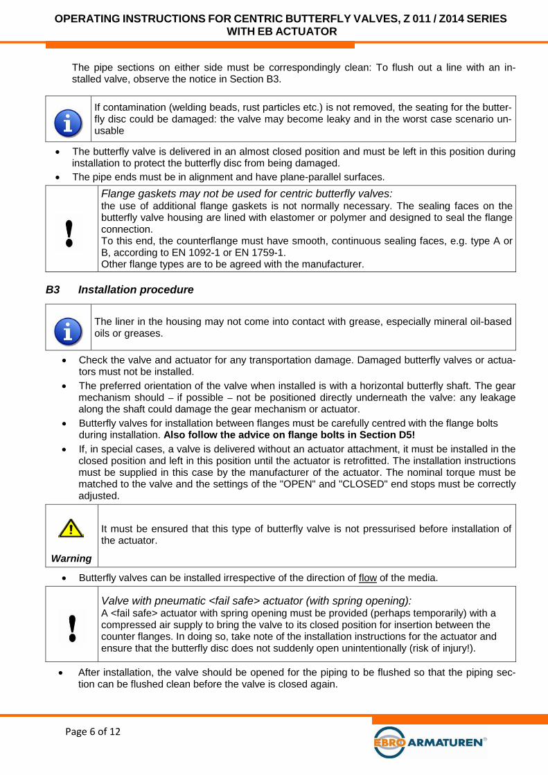
The pipe sections on either side must be correspondingly clean: To flush out a line with an in-stalled valve, observe the notice in Section B3.
If contamination (welding beads, rust particles etc.) is not removed, the seating for the butter-fly disc could be damaged: the valve may become leaky and in the worst case scenario un-usable
• The butterfly valve is delivered in an almost closed position and must be left in this position during installation to protect the butterfly disc from being damaged.
• The pipe ends must be in alignment and have plane-parallel surfaces.
Flange gaskets may not be used for centric butterfly valves: the use of additional flange gaskets is not normally necessary. The sealing faces on the butterfly valve housing are lined with elastomer or polymer and designed to seal the flange connection. To this end, the counterflange must have smooth, continuous sealing faces, e.g. type A or B, according to EN 1092-1 or EN 1759-1. Other flange types are to be agreed with the manufacturer.
B3 Installation procedure
The liner in the housing may not come into contact with grease, especially mineral oil-based oils or greases.
• Check the valve and actuator for any transportation damage. Damaged butterfly valves or actua-tors must not be installed.
• The preferred orientation of the valve when installed is with a horizontal butterfly shaft. The gear mechanism should – if possible – not be positioned directly underneath the valve: any leakage along the shaft could damage the gear mechanism or actuator.
• Butterfly valves for installation between flanges must be carefully centred with the flange bolts during installation. Also follow the advice on flange bolts in Section D5!
• If, in special cases, a valve is delivered without an actuator attachment, it must be installed in the closed position and left in this position until the actuator is retrofitted. The installation instructions must be supplied in this case by the manufacturer of the actuator. The nominal torque must be matched to the valve and the settings of the "OPEN" and "CLOSED" end stops must be correctly adjusted.
Warning
It must be ensured that this type of butterfly valve is not pressurised before installation of the actuator.
• Butterfly valves can be installed irrespective of the direction of flow of the media.
Valve with pneumatic <fail safe> actuator (with spring opening): A <fail safe> actuator with spring opening must be provided (perhaps temporarily) with a compressed air supply to bring the valve to its closed position for insertion between the counter flanges. In doing so, take note of the installation instructions for the actuator and ensure that the butterfly disc does not suddenly open unintentionally (risk of injury!).
• After installation, the valve should be opened for the piping to be flushed so that the piping sec-tion can be flushed clean before the valve is closed again.

OPERATING INSTRUCTIONS FOR CENTRIC BUTTERFLY VALVES, Z 011 / Z014 SERIES WITH EB ACTUATOR
Page 7 of 12
Before closing for the first time, hard/sharp contamination (welding beads, rust particles etc.) must be cleared from the pipe section.
• When installing at the end of a pipe section:
Danger!
If a butterfly valve is installed as an end valve and pressurised, it must be closed off with a blanking flange to prevent material damage or personal injury in the event of leakage or im-permissible opening.
• For the connection of an actuator to the system controller, follow the instructions provided by the manufacturer of the actuator.
The actuator is adjusted for the operating data given in the order: The adjustment of the "CLOSED" end stop on a valve newly delivered from the factory should not be changed so long as the valve remains tight when closed.
• To conclude the installation, a functional test must be carried out: An actuator that is fitted to the butterfly valve must move smoothly to the <OPEN> and <CLOSED> positions with the marked control data and in accordance with the commands.
• Incorrectly executed commands could be dangerous and cause damage to the piping system. Identifiable system malfunctions must be resolved before commissioning. See also Section C3 <Troubleshooting>.
B4 Pressure testing before/during commissioning All butterfly valves have undergone a final factory inspection by the manufacturer in accordance with EN12266-1. For pressure testing a valve in the system, the test conditions for the piping section apply – but with the following restrictions:
• The test pressure for the valve may not exceed 1.5x PS (as shown on the valve type plate). Dur-ing testing, the butterfly disc must be in the open position.
• If more than 1.1x PS is applied to a closed butterfly valve, there is a danger that internal parts of the valve will be overloaded. This must be avoided at all costs.
B5 Supplementary information: Deinstalling the valve The same safety rules apply as for the (piping) system and the installation (see Section B1).
• Check that the piping is free, not under pressure and emptied. • Close the valve completely, remove the flange bolts. Prise the flange apart with a tool. • Pull out the valve (when pulling out the valve, do not damage the sealing faces of the flanges)
and store in a secure place. Protect the sealing faces. • For the attachment of lifting straps, see Section A4.
Danger
If a valve must be removed from pipes containing dangerous media and removed from the system: The parts of the valve that have been in contact with the media (butterfly disc, shafts and seat ring) must be professionally decontaminated before repair.
After deinstalling the valve: The liner in the housing may not come into contact with grease, especially mineral oil-based oils or greases.

OPERATING INSTRUCTIONS FOR CENTRIC BUTTERFLY VALVES, Z 011 / Z014 SERIES WITH EB ACTUATOR
Page 8 of 12
C) Operating instructions In accordance with the provisions of the Machinery Directive 2006/42/EC, the planner of the system must draw up a comprehensive risk analysis. The manufacturer EBRO ARMATUREN provides the following documents for this purpose: • these installation and operating instructions • the declaration on EC Directives included at the end
These instructions include safety notices for foreseeable risks arising when using the valves in industrial applications. It is the planner’s/operator’s responsibility to supplement these instructions for other risks specifically linked to the system.
C1 Safety instructions for operation and maintenance
Danger
• The function of the valve must comply with the <Intended use>, which is described in Section A2.
• The conditions of use must comply with the specifications shown on the valve type plate.
• All necessary maintenance work to be carried out on the valve is to be carried out only by qualified personnel. For the purposes of these instructions, qualified personnel are persons who, on the basis of their training, specialist knowledge and professional ex-perience, can correctly assess and execute the work assigned to them and can identi-fy and avoid potential risks.
• Before undoing a screw plug or screw from the housing cover or before deinstalling the whole valve from the piping system, the pressure in the system or pipe sections on either side of the valve must be reduced to zero so that the medium does not leak out of the piping in an uncontrolled manner.
• Operation of an actuator mounted on a valve is only permissible if the valve is en-closed on both sides by a section of pipe or equipment – any prior actuation entails a risk of crushing and is the sole responsibility of the user.
Risk of
crushing
C2 Automatic operation The valve is closed by rotating the shaft in a clockwise direction and opened by rotating anti-clockwise. A valve fitted with an actuator is to be operated using signals from the controller. Butterfly valves deliv-ered direct from the factory with an actuator have already been precisely adjusted – this adjustment in the gear mechanism/actuator should not be changed so long as the valve operates faultlessly. The only maintenance required is a visual inspection of the external tightness of the flange connection at suitable time intervals – in the event of leakage see Section C3 <Troubleshooting>.
In the case of butterfly valves that remain in one position for long periods, it is recommended that they are actuated at regular intervals to ensure freedom of movement.

OPERATING INSTRUCTIONS FOR CENTRIC BUTTERFLY VALVES, Z 011 / Z014 SERIES WITH EB ACTUATOR
Page 9 of 12
C3 Troubleshooting Type of problem Countermeasure
Leakage at the flange connection to the piping
Seal the flange connection between the housing and piping: Observe instructions in operating instructions for the piping system and EBRO installation note EW 1806 (see Section D5).
If the leak cannot be stopped by tightening the flange joint: Ensure that the piping flanges are in alignment and plane-parallel – and/or change the lining of the housing. Take note of Section B1 <Safety instruc-tions…> and order spare parts and the required instructions from EBRO-ARMATUREN.
Leakage at the shaft seal
If the shaft seal is leaky: it needs to be repaired: replace the shaft seal. Take note of Sections B1 and C1 <Safety instructions…> and order spare parts and the required instruc-tions from EBRO-ARMATUREN.
Leakage in the valve seating (disc/sleeve seal)
Check whether the valve is 100% closed with full actuator torque.
If the valve is still leaky in its closed position: Open/close the valve several times under pressure.
If the valve is then still leaking: it needs to be repaired: Replace housing liner (sleeve). Take note of Section C1 <Safety instructions…> and order spare parts and the required instruc-tions from EBRO-ARMATUREN.
Operating fault
Deinstall the valve (take note of Sections B1 and C1 <Safety instructions…>) and inspect.
If the valve is damaged: it needs to be repaired: order spare parts and the required instructions from EBRO-ARMATUREN.
In the event that a repair is required, please contact our Service Department: e-mail: [email protected]

OPERATING INSTRUCTIONS FOR CENTRIC BUTTERFLY VALVES, Z 011 / Z014 SERIES WITH EB ACTUATOR
Page 10 of 12
D) Technical appendix/planning documents Note: This appendix is not an integral part of the installation and operating instructions. It is only an extract from the catalogue docu-ments of EBRO-ARMATUREN for this type of valve – to request the full catalogue refer to the addresses in the contents.
D1 Technical specification of the valve Butterfly valves of the <centric> type meet the constructional standards: ► EN 593: Industrial valves - Metallic butterfly valves
D2 p/t-Ratings Depending on the operating temperature and the housing and liner materials, the maximum op-erating pressures <PS> can be found in the current EBRO catalogue. Depending on the type and/or use, the appropriate pressure-temperature diagrams must be observed.
D3 Drawing / parts list The drawings and typical parts lists for the valves can be downloaded from the EBRO "Down-load menu":
(www.ebro-armaturen.com)
D4 Spare parts In the parts lists found on the data sheets described in Section D3, the spare parts are identi-fied with the indication "(empfohlenes Ersatzteil / recommended spare part)". Only EBRO original parts may be fitted. Order spare parts and the required instructions from EBRO ARMA-TUREN.
D5 Flange bolts for centric valves The flange bolts and installation notices for the valves are to be found in the EBRO ARMA-TUREN factory standard sheets EW1806 to EW1810 and EW1830 ff. These can be download-ed from the "Download area" (for address see page 2 or the link below).
(www.ebro-armaturen.com)
OPERATING INSTRUCTIONS FOR CENTRIC BUTTERFLY VALVES, Z 011 / Z014 SERIES WITH EB ACTUATOR
Page 11 of 12
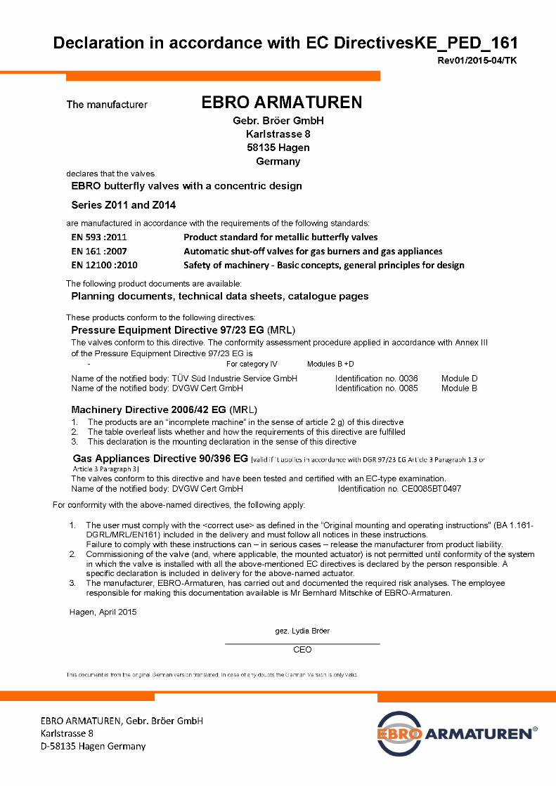
Declaration of conformity with EC Directives

OPERATING INSTRUCTIONS FOR CENTRIC BUTTERFLY VALVES, Z 011 / Z014 SERIES WITH EB ACTUATOR
Page 12 of 12
The manufacturer EBRO ARMATUREN Gebr. Bröer GmbH, D58135 Hagen declares that the valves EBRO butterfly valves Z011 / Z014 with a concentric design meet the following requirements: Requirements according to Annex I, Machinery Directive 2006/42/EC 1.1.1., g) Intended use See installation & operating instructions 1.1.2., c) Incorrect use warnings See installation & operating instructions 1.1.2., c) Required protective equipment Exactly as for the pipe section in which the valve is installed 1.1.2., e) Accessories No special tool is required for changing worn parts
1.1.3 Components in contact with media All materials coming into contact with the medium are specified in the type data sheet and the or-der confirmation. It is a prerequisite that the user carries out an appropriate risk analysis.
1.1.5 Handling Fulfilled by the notices in the installation instructions 1.2 and 6.2.11 Control The responsibility of the user and in accordance with the installation instructions for the actuator
1.3.2 Prevention of breakage risks for valve parts withstanding pressure: Certified by declaration of conformity with PED 97/23 EC For functional components: assured if actuator correctly used
1.3.4 Sharp corners and edges Requirement fulfilled
1.3.7/.8 Risk of injury by moving parts Requirement fulfilled if used as intended. Maintenance and repair only if valve/actuator stopped
1.5.1 – 1.5.3 Power supply The responsibility of the user. See also instructions for the actuator
1.5.5 Exceeding permissible temperature See warning notices, installation and operating instructions, Section <Intended use>
1.5.7 Explosion -protection required. Must be expressly agreed in purchase order. In this case: use only as marked on the valve.
1.5.13 Emission of hazardous substances Not applicable 1.6.1 Servicing See operating instructions Clarify if parts subject to wear are in stock with EBRO-ARMATUREN.
1.7.3 Marking Valve: in accordance with installation instructions Actuator: in accordance with installation instructions
1.7.4 Operating instructions Necessary additions to the overall instructions for the <complete machine> are summarised in the operating Instructions, see Section C of the installation and operating instructions
Requirement according to Annex III The valve is not a <complete machine>: it therefore has no CE marking for conformity with the Machinery Directive
Requirements according to Annex IV and Annexes VIII-XI not applicable
Requirements according to EN 12100:2010
1. Applicability
The risk analysis for the valve/actuator is drawn up from the aspect of an <incomplete machine>. The analysis was based on the product standard EN593:<Industrial valves - Metallic butterfly valves> with an actuator in accordance with EN15714-2 or EN15714-3, Class A. Furthermore, it is based on industrial use and an average of >20 years’ experience in the use of the above-named type of valves. This analysis led to the notices and warnings in the above-named installation instructions and operating instructions. Note: it is essential that the user carries out a risk analysis of the pipe section and the valves installed therein that is
specially adapted to the operating conditions in accordance with Sections 4 to 6 of EN 12100 – such an analy-sis is not possible for the manufacturer, EBRO ARMATUREN in respect of standard valves.
3.20, 6.1 Inherently safe design The butterfly valves are manufactured according to <inherently safe design> principles. <Intended use> is a necessary precondition.
Analysis according to Sections 4, 5 and 6 Experience of faulty operation and misuse documented by the manufacturer in the context of cas-es of damage (documentation in accordance with ISO9001) was used as the basis.
5.3 Limits of the machine Limiting of the incomplete machine was carried out in accordance with the <Intended use> of both the valve and the actuator.
5.4 Decommissioning, disposal Not within the responsibility of the manufacturer
6.2.2 Geometric factors Since the valve and actuator comprise the functional parts when used as intended, this section does not apply.
6.3 Technical protective devices Only required for special actuators – see confirmation of order.
6.4.5 Operating instructions Since valves with actuators work automatically based on the command signals from the controller, the operating instructions describe those aspects that are <typical of the valve> and must be pro-vided to the manufacturer of the piping system.
7 Risk analysis The risk analysis was carried out in accordance with Annex VII, B) by the manufacturer EBRO ARMATUREN and is documented in accordance with MD Annex VII B).
Requirements in accordance with EN 161 :2007 as shown in supplementary sheet <EN 161 requirements for version 1.161>