cdio-oriented inverted pendulum control ......proceedings of the 8th international cdio conference,...
TRANSCRIPT

Proceedings of the 8th International CDIO Conference, Queensland University of Technology, Brisbane, July 1 - 4, 2012
CDIO-ORIENTED INVERTED PENDULUM CONTROL PROJECT FOR
UNDERGRADUATE ENGINEERING STUDENTS
John Gallagher and Bill Goodwine
Department of Aerospace & Mechanical Engineering, University of Notre Dame, USA ABSTRACT This paper presents the design of an undergraduate pendulum feedback control project. The project is low-cost, significantly less expensive than commercially-available systems, and the project based upon it requires, and hence reinforces, substantive understanding of the physics and control-theoretic aspects of the problem in order for students to complete it. This paper presents the pedagogical purpose behind the project experience for the students and also many details of the physical design of the system and the software control system so that it will be straight-forward to replicate elsewhere. This paper is indented to contribute to the “CDIO Knowledge Library” to facilitate projects that implement the “design” and “implement” components of CDIO, with the future goal of extending the scope of the project to include the “conceive” and “operate” components. In order to accomplish this goal, a significant portion of this paper must present the technical aspects of the project which is integral with and shares equal footing with the broader pedagogical goals. KEYWORDS Project-based learning, active learning, feedback control. INTRODUCTION
This paper presents an undergraduate controls project platform and associated project outline intended to enhance student learning by appropriately requiring them to work though all the steps necessary to implement a digital feedback controller on a real physical system. In the form described in this paper, students are given a physically-assembled system and their task is to design and implement a feedback controller to stabilize the pendulum in inverted configurations. In order to accomplish that objective, students must be able to write programs for the microcontroller, perform system identification, use appropriate analysis tools and insight to design a feedback controller, convert the controller to a discrete-time controller, write a program to instantiate the controller, download and run the controller and systematically test and evaluate the performance on the controller. Because the project is independent of homework and other course materials, it provides an independent context in which students must master certain elements of the course material in order to successfully complete. In the implementation described in this paper, students work in teams, but the project could also be performed individually. As described in detail subsequently, the system is comprised of the following components:
• the pendulum, which is actuated by a dc motor with an associated optical encoder,

Proceedings of the 8th International CDIO Conference, Queensland University of Technology, Brisbane, July 1 - 4, 2012
• an H-bridge current supply controlled by a pulse-width modulation input signal, • a commercially-available microcontroller board, based on the Motorola/Freescale
HC11-series 8-bit microprocessors with a serial port interface, and • an interface board, which contains the circuitry to interface the microcontroller with
the H-bridge and optical encoder. Programs executed on the microcontroller are written and compiled on a workstation, and can be downloaded to the EEPROM on the microcontroller board via a serial port. It is well-established that active and reflective learners are not well served by traditional university engineering lectures [ 1 ]. As such, there is wide recognition that project-based experiences enhance both student satisfaction, learning and retention [ 2 ]. Active learning is, of course, an element of the broader framework of the CDIO initiative and this project was specifically designed with the purpose of the CDIO Initiative and related engineering education goal in mind. In the Department of Aerospace and Mechanical Engineering at the University of Notre Dame, this project has been implemented in AME 30315, Differential Equations, Vibrations and Control II. This course is required in both the Aerospace Engineering and Mechanical Engineering Programs. Nominally, students take this course in the spring semester of their third year; however, if a student has Advanced Placement credit for the first two calculus courses in their Program, they may take the course during the spring of their second year. Mechanical Engineering students typically concurrently take EE 20222, Introduction to Electrical Engineering and Embedded Systems, a significant portion of which considers programming embedded microprocessors. Hence, the majority of the Mechanical Engineering students have programming experience relevant to successfully completing the project and typically third-year Mechanical Engineering students comprise a majority of the students enrolled in AME 30315. Hence, in the Spring of 2012, the project was assigned as a group project, with typical groups of two students, one of whom was a Mechanical Engineering student who had either completed EE 20222 or was concurrently enrolled in it. In the Spring semester of 2012, AME 30315 had approximately 130 students enrolled and ten pendulum platforms were constructed and stored in the Stinson-Remick Hall of Engineering where students would have 24/7 access to the projects. A web page for the Spring, 2012 implementation of the project was developed to guide the students through the project [ 3 ]. PROJECT DESIGN AND LEARNING OUTCOMES As indicated previously, the student experience in the project is designed such that a necessary condition for successful completion of the project is substantive understanding of system identification and modelling, feedback control analysis and design, embedded systems programming and post-design validation of the design. The project may be divided into five sequential steps:
1. an introductory step where students become familiar with the system, including operating the hardware, compiling programs, downloading the programs to the microcontroller and executing the programs,
2. system identification where a student-written program controls the system in a stable mode (with the pendulum hanging “down”) and the step response of the system is obtained and analysed to determine a second-order transfer function for the system, which is then modified to represent the pendulum when it is in the unstable configuration (pointing “up),
3. feedback controller design and analysis using root locus and other analysis techniques,
4. controller software programming, which requires converting the controller design to a discrete-time transfer function and implementing it in the C programing language, and

Proceedings of the 8th International CDIO Conference, Queensland University of Technology, Brisbane, July 1 - 4, 2012
5. running the feedback controller on the pendulum in an unstable configuration and analysing and validating the performance of the controller design.
A detailed description of each of these steps is presented subsequently in this paper. Student outcomes for the course are enhanced by this project. Specifically, after completing the project, students will be able to:
1. download a program saved in an S-record format (an .s19 file) to the EEPROM on the microcontroller board and configure the system to execute the program,
2. write a computer program in the C programming language to execute on the microcontroller including:
a. programming and handling interrupts (both output-compare and pulse-accumulator interrupts), and
b. determining the status of microcontroller input pins through bit-masking, 3. perform a system identification and validation procedure on the pendulum by
commanding a step input when then pendulum is in the stable (down) position and modifying the model obtained to apply to the unstable (up) position of the pendulum,
4. use the model identified to analyze appropriate feedback controller designs, including accounting for modelling errors such as unmodelled geometric nonlinearities and friction,
5. design, program and verify a lead compensator to satisfy transient response specifications for the system, including quantified rise time, settling time and overshoot,
6. design, program and verify a lag compensator to satisfy steady-state specifications for the response of the system,
7. design a lead-lag compensator to satisfy transient and steady-state specifications, with recognition of the trade-offs between them, and
8. operate and validate their controller design. This project involves a significant number of elements of the CDIO Syllabus [ 4 ]. In particular, in version 2.0 at the second level of detail, this project incorporates
1. system identification, model simplification and model validation incorporates elements from sections 1.1, 1.2, 1.3, 2.1 and 2.2,
2. controller design incorporates elements from sections 1.1, 1.2, 1.3, 2,1, 2.3 and 4.4, 3. implementation of the design incorporates elements from 2.1-2.4 and 4.5, 4. validation and analysis of performance incorporates elements from 2.1-2.4 and 4.6,
and 5. if implemented in teams with reporting requirements, the project further incorporates
elements from 3.1, 3.2 and 4.7. STUDENT EXPERIENCE PROJECT DESIGN This section presents the details of each of the steps the students must perform to complete the project. It also presents an overview of the technical content necessary to complete the project. Introduction and Familiarization with the Pendulum System As the project is currently implemented, students are not required to design or assemble any of the physical components of the system. However, some degree of familiarization is necessary before they can effectively work with the system. In this introductory step, students are provided with an S-record that commands a square-wave torque to the motor with a period of approximately ten seconds. In response to this input when in the downward stable configuration, the pendulum will respond as illustrated in Figure 1. The students are provided with the C program that generated the S-record that commanded the square-wave

Proceedings of the 8th International CDIO Conference, Queensland University of Technology, Brisbane, July 1 - 4, 2012
torque. In order to record the response, students must modify the program to print the time and position of the pendulum to the serial port at some specified rate and to capture the data from the serial port. System Identification Analysis and design of the feedback controller requires a differential equation model for the system, which in standard controls applications is given as a transfer function. From Figure 1, assuming a second-order transfer function of the form
Θ(s)Τ(s)
=F
s2 + 2ζωns+ωn2 ( 1 )
where ωn is the natural frequency, ζ is the damping ratio and F is a scale factor, is reasonable. Correctly determining the three parameters from the response of the system requires the students to take into account scaling the transfer function both in the units of the angular position and in time, and is done by the usual method of the logarithmic decrement [ 5 ]. The graph on the right in Figure 1 is the response to a step input with magnitude -60 [Pu], where the units are “pulsewidth units” with a range of values from -400 to +400 corresponding respectively to full negative and positive torque commands to the motor from the current controller. Using the logarithmic decrement approach, numerical values for the physical parameters are computed as represented by the following transfer function Θ(s)
Τ(s)=
−10.5s2 + 0.72s+36
. ( 2 )
the step response of this transfer function to an input of magnitude -60 is also plotted on the right in Figure 1. Students must identify the sources of error in the modelling process, which include, for example, the actual system response is characterized by Coulomb damping, in contrast to viscous damping assumed in the logarithmic decrement, and the fact the real pendulum is nonlinear. Experimentation may validate conclusions with respect to sources of error.
Figure 1: Square-wave torque response of pendulum in stable configuration (left) and comparison with system-identification transfer function (right).
Proceedings of the 8th International CDIO Conference, Queensland University of Technology, Brisbane, July 1 - 4, 2012
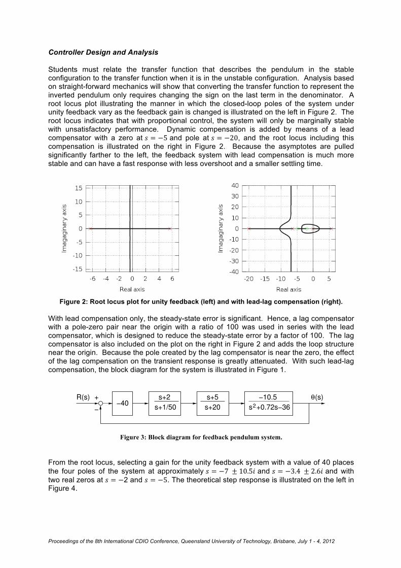
Controller Design and Analysis Students must relate the transfer function that describes the pendulum in the stable configuration to the transfer function when it is in the unstable configuration. Analysis based on straight-forward mechanics will show that converting the transfer function to represent the inverted pendulum only requires changing the sign on the last term in the denominator. A root locus plot illustrating the manner in which the closed-loop poles of the system under unity feedback vary as the feedback gain is changed is illustrated on the left in Figure 2. The root locus indicates that with proportional control, the system will only be marginally stable with unsatisfactory performance. Dynamic compensation is added by means of a lead compensator with a zero at 𝑠 = −5 and pole at 𝑠 = −20, and the root locus including this compensation is illustrated on the right in Figure 2. Because the asymptotes are pulled significantly farther to the left, the feedback system with lead compensation is much more stable and can have a fast response with less overshoot and a smaller settling time.
Figure 2: Root locus plot for unity feedback (left) and with lead-lag compensation (right).
With lead compensation only, the steady-state error is significant. Hence, a lag compensator with a pole-zero pair near the origin with a ratio of 100 was used in series with the lead compensator, which is designed to reduce the steady-state error by a factor of 100. The lag compensator is also included on the plot on the right in Figure 2 and adds the loop structure near the origin. Because the pole created by the lag compensator is near the zero, the effect of the lag compensation on the transient response is greatly attenuated. With such lead-lag compensation, the block diagram for the system is illustrated in Figure 1.
Figure 3: Block diagram for feedback pendulum system.
From the root locus, selecting a gain for the unity feedback system with a value of 40 places the four poles of the system at approximately 𝑠 = −7 ± 10.5𝑖 and 𝑠 = −3.4 ± 2.6𝑖 and with two real zeros at 𝑠 = −2 and 𝑠 = −5. The theoretical step response is illustrated on the left in Figure 4.
!40s+1/50
s+2 s+5 !10.52s+20 s +0.72s!36
+
!
!(s)R(s)

Proceedings of the 8th International CDIO Conference, Queensland University of Technology, Brisbane, July 1 - 4, 2012
Figure 4: Step response of the system, theoretical (left) and actual system (right).
Controller Implementation in Software In order to implement the controller design in a digital microprocessor, the representation of the compensator in continuous time must be converted to discrete time. Representation of discrete-time engineering systems and control thereof is a well-developed subject (see, for example [ 6 ], [ 7 ]). However generally for aerospace and mechanical engineering students, modelling in continuous time is more natural and the recommended approach in this paper is to design the controller in continuous time and then to convert the controller to an appropriate digital form when it is implemented in a program for the microcontroller. A relatively straight-forward method to do this is the so-called Tustin’s method [ 8 ], which is based on the trapezoid integration method, where the relationship between the continuous time independent variable in the frequency domain, s, and the discrete-time independent variable, z, is given by
s = 2
T1− z−1
1+ z−1"
#$
%
&' ( 3 )
where T is the discrete time step. In continuous time multiplication by s represents differentiation and in discrete time multiplication by z represents a shift to the next step in discrete time, i.e., zθ(nT ) =θ((n+1)T ). ( 4 ) Thus, for example, for a lead-lag compensator which takes the error signal and computes the input torque of the form
C(s) = k s+ 2s+1/ 50!
"#
$
%&s+ 5s+ 20!
"#
$
%& ( 5 )
if τ (nT ) is the control torque at time t = nT then using Eqns. ( 4 ) and ( 5 ) and setting T =1/ 20 , the control torque at the next time step may be computed by by

Proceedings of the 8th International CDIO Conference, Queensland University of Technology, Brisbane, July 1 - 4, 2012
τ t +T( ) =
−3148e t +T( )+ 5297e t( )− 2216e t −T( )+13300τ t( )+3300τ t −T( )10000
( 6 )
where the units for the torque are in pulsewidth-units [Pu], the units for the error function, 𝑒 𝑡 , are [deg]x100 and the equation has been scaled by a factor of 10,000 because the processor is limited to integer arithmetic Validation Once the controller is programmed and executed, students must validate their design. The pole locations for the closed-loop system should predict system response. Students must compare the response predicted by both theory and simulation to the system response and explain any significant variations. Because of the geometric nonlinearities in the system, the model used in the design is accurate only for angles where sin 𝜃 ≈ 𝜃, which is, of course, for small values of the angle. Students must validate this fact by attempting to stabilize the pendulum at angles far from zero, recording and presenting the response and explaining deviations from the theoretically-predicted performance. The actual step response of the closed-loop system with the controller is illustrated on the right in Figure 4. Comparing the two step responses in Figure 4 indicates the step response of the real system has more overshoot, less damping and a somewhat higher natural frequency than the response of the mathematical model. Students are required to experiment with the system to determine the source of modelling errors. PROJECT PHYSICAL DESIGN
A photograph of the system with some of the components labelled appears in Figure 5. The physical components of the pendulum can be grouped into two sections: the mechanical and the electrical. All of the components are necessary to build the pendulum are listed in the bill of materials [ 9 ]. Mechanical Components The pendulum itself consists of an arm made of a thin steel rod with a rubber mass attached at the end. The arm is attached directly to the shaft of a small 12V DC brushed motor using a jaw shaft coupler. The motor has a 500-count encoder attached, which is used for position feedback. The encoder also has a ‘Z’ channel, which can be used to determine the absolute position of the pendulum arm. The rotational motion of the arm is limited on either side by rubber stops which allow the pendulum a total range of motion of about 110°. The shaft has two strips of reflective material which align with an infrared emitter when the arm is pushed against the two hard stops. A phototransistor senses the reflected light, allowing the software to recognize when the pendulum is in the limit position. The assembly of the motor and arm are mounted to a polycarbonate base, as are the electrical boards. The aluminium frame above the base allows the entire frame to be turned upside down. Thus the pendulum can be easily changed from inverted to non-inverted, which facilitates system identification, because system identification is best performed by analyzing the naturally stable non-inverted pendulum. Part and assembly drawings are provided for the frame and base [ 9 ].

Proceedings of the 8th International CDIO Conference, Queensland University of Technology, Brisbane, July 1 - 4, 2012
Figure 5: Photograph of pendulum system.
Electrical Components A schematic of the basic layout of the electrical components is provided in Figure 6. More detailed wiring diagrams, such as would be needed to construct a pendulum, are provided as well [ 9 ]. Most of the electronic components are located either on the commercially available microcontroller board, or on the interface board designed specifically for this pendulum project. The microcontroller, a MicroStamp11 from Technological Arts, uses a Motorola/Freescale 68HC11 microprocessor, which was for many years one of the most commonly used in industry. The microprocessor has very limited capability, but is correspondingly inexpensive; hence, it reflects an industrial reality of using limited capability where it makes good design sense. The controller receives position feedback from the encoder via a decoder chip on the interface board, which transforms the two-channel encoder output into a pulse and direction signal, which is simpler for the controller to decipher. The controller uses the feedback to calculate the necessary torque to output, and generates a pulse-width modulated (PWM) signal. This signal is sent to an H-bridge which switches the current to the motor on and off at the proper intervals to provide the torque commanded. The MicroStamp11 also has a serial port which is used to download programs to the controller, and can be used to print out any variables or other desired information to a terminal on the connected computer. The interface board also features test points for all of major I/O on the controller, which facilitates debugging and analysis of the entire project using a logic analyzer or oscilloscope. Also on the interface board is a set buttons which can be accessed by the microcontroller, and can be used for tasks such as varying the target position or gains without recompiling and downloading the program.
Motor
Pendulum Arm
Encoder
Microprocessor
H-Bridge
Interface Board

Proceedings of the 8th International CDIO Conference, Queensland University of Technology, Brisbane, July 1 - 4, 2012
Figure 6: Pendulum system electrical components schematic.
CONTROL SOFTWARE DESIGN For the student project, a framework code is provided with most of the functionality necessary already programmed [ 10 ]. The students must then modify that code to perform the system identification, and then to implement their controller. Control Code The code provided to the students, diagramed in Figure 7, is written in C, and has two major parts: initialization, and then a continuous control loop. The code first performs hardware initialization, and then waits for the pendulum to be moved through absolute zero by the user, so that the absolute position of the pendulum can be determined. Once this done, the code can track the absolute position by incrementing a variable each time a pulse is received from the decoder chip. Each pulse triggers an input capture interrupt on the HC11, and the interrupt handler polls the direction signal from the decoder to determine whether to increment the position variable up or down. Once this initialization is performed, the program loops continuously at a frequency of 20Hz. In this 20Hz loop, the error between the current and desired positions of the pendulum is calculated, and then the torque needed is calculated. The calculation of the torque using the error is not provided to the students. The value of torque is then used to set the PWM percentage, by calculating the number of clock cycles the signal must remain high, and how many it must remain low. The actual signal is set by an output compare interrupt. Each time this interrupt is received, it toggles the PWM pin on the controller, and sets the next interrupt
I/O SUMMARY:PA0 Rotational LimitPA1 Decoder Direction InputPA2 Encoder Channel I (top)PA3 H-Bridge Fault StatusPA4 SparePA5 H-Bridge PWM1 ControlPA6 SPARE (output only)PA7 Decoder Clock InputPD0 Serial RX Input (NC)PD1 Serial Out to LCD 9600 BaudPD2 Left/Right Status LEDsPD3 Center PushbuttonPD4 UP PushbuttonPD5 DOWN PushbuttonXIRQ Status 1 FaultIRQ Status 2 Fault
REVISION HISTORYA - CAN'T REMEMBERB - ADDED DECODER LS7084 10/19/06C - ADDED INPUT/OUTPUT DESCRIPTIONSD - CORRECTED TDC RESPONSE 3-30-09E - ADDED LOGIC ANALYZER TEST POINTSF - REMOVED PA6 LIMIT SWITCH ENABLEG - ADDED INTERRUPT JUMPER BLOCKH - CHANGED H-BRIDGE TYPE
T.D.C.*
*Top Dead Center
LIMIT

Proceedings of the 8th International CDIO Conference, Queensland University of Technology, Brisbane, July 1 - 4, 2012
to happen after the appropriate number of counts. After the PWM percentage is calculated, the current position and commanded torque are printed over the serial port, and then program waits to begin the next loop.
Figure 7: Flowchart of control program code. There are two interrupts that are enabled and handled. One is an output compare interrupt that is used for the PWM signal (programmed as OC3 in the current implementation). The other is a pulse-accumulator interrupt that is triggered each time an edge is encountered on the encoder (programmed as the PAI interrupt in the current implementation). The C compiler used for this project is an open source and cross-platform port of Gnu Compiler Chain (GCC) for the 68HC11 [ 11 ]. PRELIMINARY ASSESSSMENT As of this writing, formal and quantified assessment data regarding the effect of participation in the project on class performance (for example on the final exam) is not available. However, many student hours have been dedicated to the project and indirect assessment based on interaction with students has been obtained. The main positive message is that the project does help elucidate the “bigger picture” aspects of control. As an example, many students were wondering where to “program the transfer function” they determined for the pendulum. In fact, that transfer function is used as part of the analysis in the design of the controller, but ultimately the microcontroller only reads the angle, computes the torque and sets the torque. The purpose of determining the pendulum transfer function was to design a controller with predictable performance, but the
Calculate error
Calculate torque
Set torque
Print variables over serial port
Wait to execute
next loop
Hardware Initialization
Reset
Wait for pendulum to be moved through vertical
Set timer to interrupt at next switch
Return
Toggle PWM pin
PWM Interrupt
Return
Encoder Interrupt
Poll direction signal
Increment position variable

Proceedings of the 8th International CDIO Conference, Queensland University of Technology, Brisbane, July 1 - 4, 2012
physical pendulum takes care of its own dynamics, of course, and does not need a transfer function programmed anywhere in the physical system. There were two negative components to students’ responses. First, as indicated previously, only half of the class was proficient in programming in C, which was the language used to program the microcontroller. This was addressed by assigning teams for the projects and ensuring that at least one member of the team had the required programming background. However, the students felt it was difficult to equitably share the workload with this disparity in skills. Another issue is that the project was due on the last day of classes because the control theory material is typically covered near the end of the semester. Student workload increases dramatically near the end of the semester, and in future years the control theory material will be presented sooner so that the students may finish the project earlier. CONCLUSIONS AND FUTURE WORK This paper presented the physical and software design of an inverted pendulum project for undergraduate engineering students. The design of the project is also presented, outlining the student experience and pedagogical aspects of the project. Assessment of the degree to which students achieve the desired project outcomes will be available after final exams at the University of Notre Dame in the Spring of 2012. The authors would like to acknowledge the assistance of Mr. Greg Brownell, Microprocessor Technician in the Department of Aerospace and Mechanical Engineering at the University of Notre Dame, who designed most of the physical aspects of the system. Additionally, the authors would like to acknowledge the assistance of Raymond LeGrand, Blair Rasmus and Derek Wolf, undergraduate students in the Department of Aerospace and Mechanical Engineering at the University of Notre Dame, who contributed significantly to the software and control algorithm development of the system. Finally, the authors would like to acknowledge the financial support of the Department of Aerospace and Mechanical Engineering at the University of Notre Dame. REFERENCES [ 1 ] Felder, R.M. and Silverman, L.K., “Learning and Teaching Styles: In Engineering Education”,
Engineering Education, Vol. 78, No. 7, 1988, pp674-681. [ 2 ] Meyers, C. and Jones, T.B., Promoting Active Learning. Strategies for the College Classroom.
Jossey-Bass, Inc., 1993. [ 3 ] http://controls.ame.nd.edu/mediawiki/index.php/Pendulum_Project [ 4 ] Crawley, E.F., Malmqvist, J., Lucas, W.A., Brodeur, D.R., “The CDIO Syllabus v2.0: An
Updated Statement of Goals for Engineering Education” Proceedings of the 7th International CDIO Conference, Technical University of Denmark, http://www.cdio.org/framework-benefits/cdio-syllabus, 2011.
[ 5 ] Bill Goodwine, Engineering Differential Equations, Springer, 2010. [ 6 ] Franklin, G.F., Powell, J.D, and Workman, M., Digital Control of Dynamic Systems, Pearson
Eduction, Third Edition, 2005. [ 7 ] Ogata, K., Discrete-Time Control Systems, Prentice Hall, Second Edition, 1995.

Proceedings of the 8th International CDIO Conference, Queensland University of Technology, Brisbane, July 1 - 4, 2012
[ 8 ] Franklin, G.F., Powell, J.D, and Emami-Naeini, A., Feedback Control of Dynamic Systems, Prentice Hall, Sixth Edition, 2009.
[ 9 ] Bill of Materials: http://controls.ame.nd.edu/courses/ame30315/pendulum/parts_list.pdf Base Drawing: http://controls.ame.nd.edu/courses/ame30315/pendulum/base_drawing.pdf Frame Drawing: http://controls.ame.nd.edu/courses/ame30315/pendulum/frame_drawing.pdf Detailed Schematic 1: http://controls.ame.nd.edu/courses/ame30315/pendulum/interface1.pdf Detailed Schematic 2: http://controls.ame.nd.edu/courses/ame30315/pendulum/interface2.pdf Detailed Schematic 3: http://controls.ame.nd.edu/courses/ame30315/pendulum/interface3.pdf [ 10 ] Provided Code: http://controls.ame.nd.edu/courses/ame30315/pendulum/code/
StudentCode.c, serial.c, vectors.c, mc.h and hc11.h are necessary to compile the baseline code. The file memory.x is specific to the gcc compiler.
[ 11 ] http://www.gnu.org/software/m68hc11/m68hc11_gcc.html Biographical Information John Gallagher is an undergraduate at the University of Notre Dame. He plans to graduate in May of 2012 with a B.A. in Philosophy and a B.S. in Mechanical Engineering. He is a member of Tau Beta Pi Engineering Honor Society and Pi Tau Sigma Mechanical Engineering Honor Society. Bill Goodwine is an Associate Professor in the Department of Aerospace and Mechanical Engineering at the University of Notre Dame. He received his M.S. and Ph.D. degrees in Applied Mechanics from the California Institute of Technology and has been the recipient of a U.S. National Science Foundation CAREER award. He has been awarded teaching awards from his department, college, university and ASEE section. His teaching and research focuses on dynamical systems and control. Corresponding author Dr. Bill Goodwine 365B Fitzpatrick Hall of Engineering University of Notre Dame Notre Dame, IN USA 46556 1-574-631-3283 [email protected]