ccp4 chicago 2011: substructure solution -...
TRANSCRIPT

Tim Grüne
CCP4 Workshop Chicago 2011Phasing & Substructure Solution
Tim GrüneDept. of Structural Chemistry, University of Göttingen
June 2011http://shelx.uni-ac.gwdg.de
CCP4 Chicago 2011: Substructure Solution 1/50
Tim Grüne
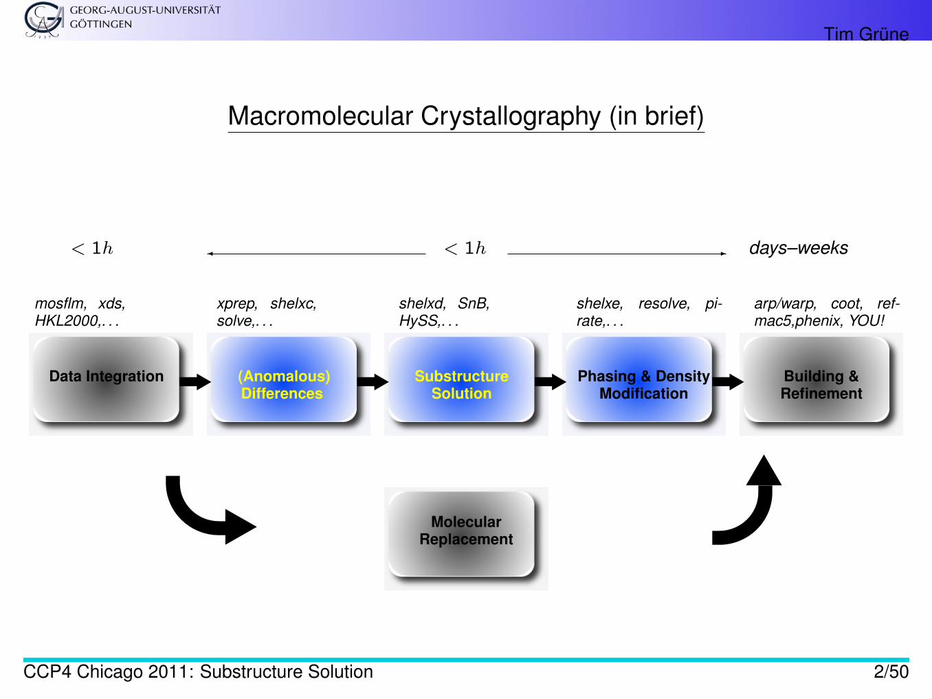
Macromolecular Crystallography (in brief)
Data Integration (Anomalous)Differences
SubstructureSolution
Phasing & DensityModification
Building &Refinement
mosflm, xds,HKL2000,. . .
xprep, shelxc,solve,. . .
shelxd, SnB,HySS,. . .
shelxe, resolve, pi-rate,. . .
arp/warp, coot, ref-mac5,phenix, YOU!
MolecularReplacement
< 1h � < 1h - days–weeks
CCP4 Chicago 2011: Substructure Solution 2/50
Tim Grüne
Motivation: The Phase Problem
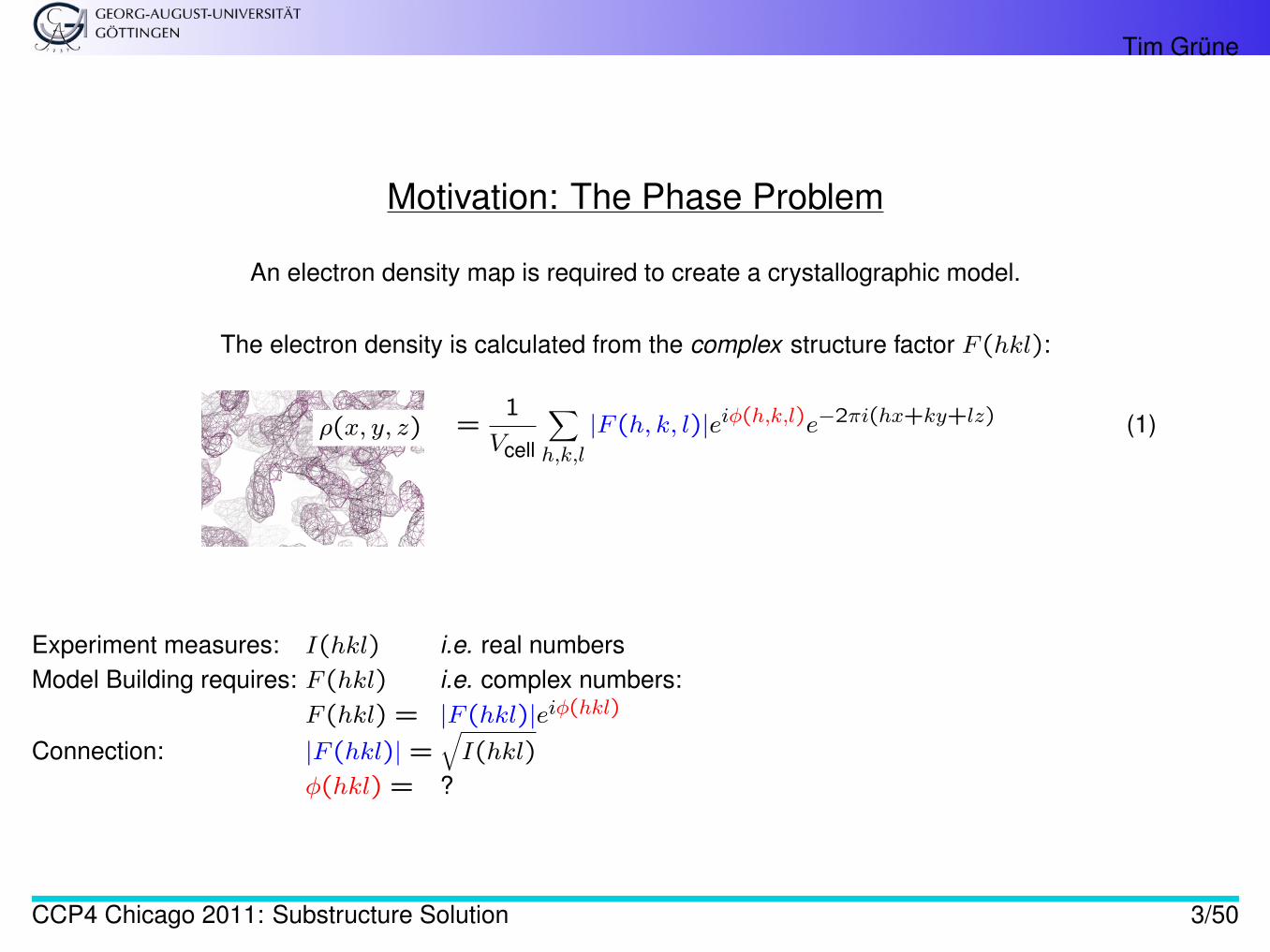
An electron density map is required to create a crystallographic model.
The electron density is calculated from the complex structure factor F (hkl):
ρ(x, y, z) =1
Vcell
∑h,k,l
|F (h, k, l)|eiφ(h,k,l)e−2πi(hx+ky+lz) (1)
Experiment measures: I(hkl) i.e. real numbersModel Building requires: F (hkl) i.e. complex numbers:
F (hkl) = |F (hkl)|eiφ(hkl)
Connection: |F (hkl)| =√I(hkl)
φ(hkl) = ?
CCP4 Chicago 2011: Substructure Solution 3/50
Tim Grüne
Motivation: The Phase Problem
The phase problem is one of the critical steps in macromolecular crystallography:
A diffraction experiment only delivers the amplitude |F (hkl)|, but not the phase φ(hkl) of the structure factor.
Without phases, a map cannot be calculated and no model can be built.
CCP4 Chicago 2011: Substructure Solution 4/50
Tim Grüne
Solutions to the Phase Problem
The main methods to overcome the phase problem in macromolecular crystallography (i.e. to obtain initialphases):
• (multi/ single) wavelength anomalous dispersion (MAD, SAD)• (multiple/ single) isomorphous replacement (MIR, SIR)• molecular replacement (MR)
and combinations thereof (SIRAS, MR-SAD, . . . ).
The first two methods are so-called experimental phasing methods.
They require the solution of a substructure.
CCP4 Chicago 2011: Substructure Solution 5/50
Tim Grüne
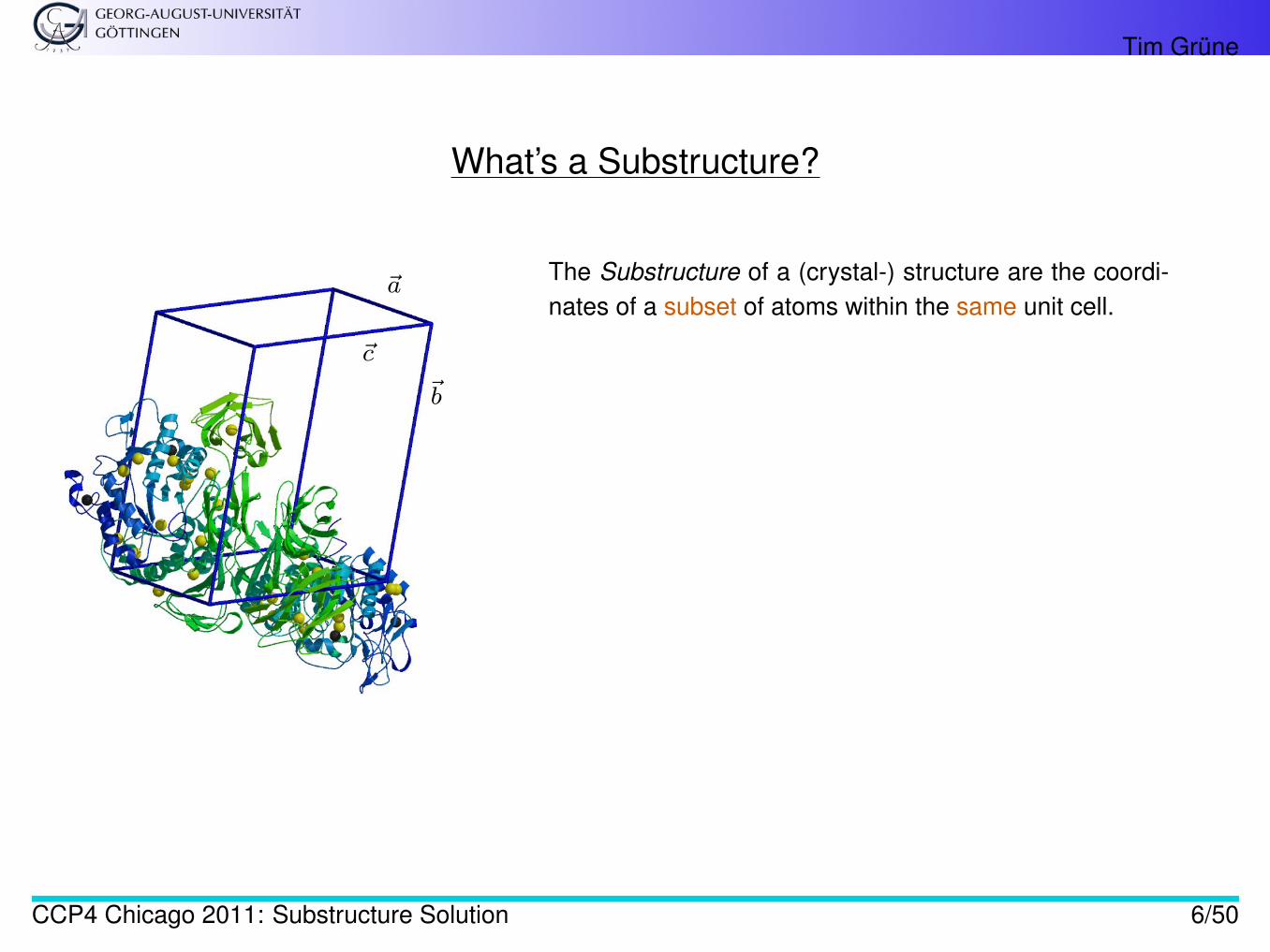
What’s a Substructure?
~a
~b
~c
The Substructure of a (crystal-) structure are the coordi-nates of a subset of atoms within the same unit cell.
CCP4 Chicago 2011: Substructure Solution 6/50
Tim Grüne
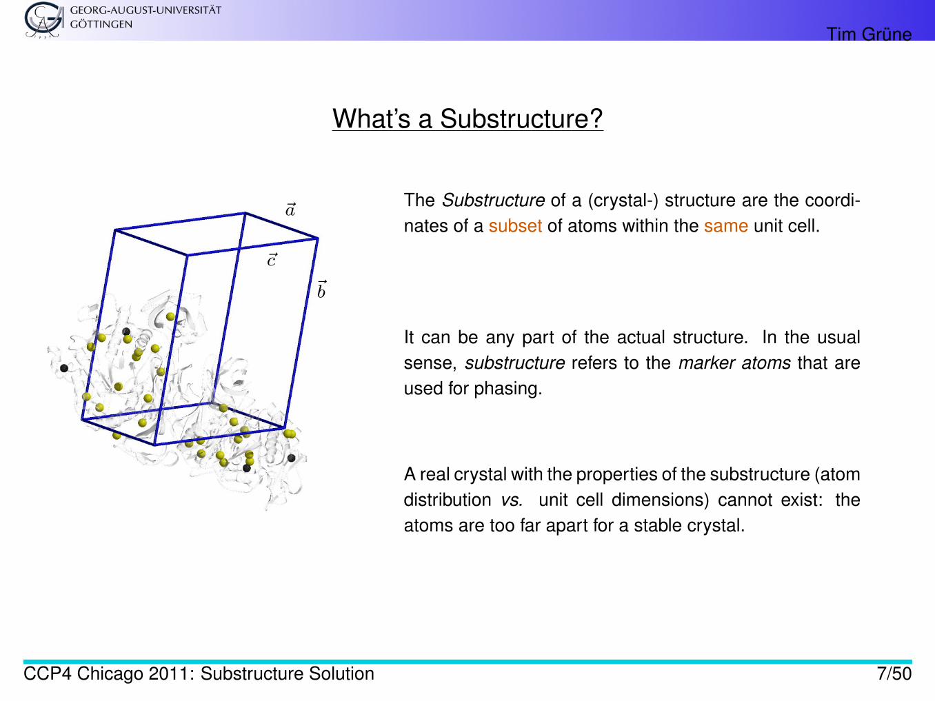
What’s a Substructure?
~a
~b
~c
The Substructure of a (crystal-) structure are the coordi-nates of a subset of atoms within the same unit cell.
It can be any part of the actual structure. In the usualsense, substructure refers to the marker atoms that areused for phasing.
A real crystal with the properties of the substructure (atomdistribution vs. unit cell dimensions) cannot exist: theatoms are too far apart for a stable crystal.
CCP4 Chicago 2011: Substructure Solution 7/50
Tim Grüne
Small Molecule Crystallography
The substructure consists of a small number of atoms in a large unit cell.
In small molecule crystallography, the phase problem is usually easily solved:
A structure with not too many atoms (< 2000 non-hydrogen atoms) can be solved by means of ab initio methodsfrom a single data set — provided the resolution is better than 1.2Å (this is called “Sheldrick’s rule” [2]).
CCP4 Chicago 2011: Substructure Solution 8/50
Tim Grüne
The Terms “Ab initio” and “Direct” Methods
ab initio Methods: phase determination directly from amplitudes, without prior knowledge of any atomic posi-tions. Includes direct methods and the Patterson method. The most widely used of all ab initio methodsare:
Direct Methods: phase determination using probabilistic phase relations — usually the tangent formula (Nobelprize for H. A. Hauptman and J. Karle in Chemistry, 1985).
CCP4 Chicago 2011: Substructure Solution 9/50
Tim Grüne
The Substructure
Central to phasing based on both anomalous dispersion and isomorphous replacement is the determination ofthe substructure.
The steps involve
1. Collect data set(s)2. Create an artificial substructure data set3. Determine the substructure coordinates with direct methods4. Calculate phases (estimates) for the actual data5. Improve phases (density modification)
CCP4 Chicago 2011: Substructure Solution 10/50
Tim Grüne
What about Sheldrick’s Rule?
The Sheldrick’s Rule says that direct methods only work when the data resolution is 1.2 Å or better.
Macromolecules seldomly diffract to this resolution.
So why can we still use direct methods to determine the substructure?
CCP4 Chicago 2011: Substructure Solution 11/50
Tim Grüne
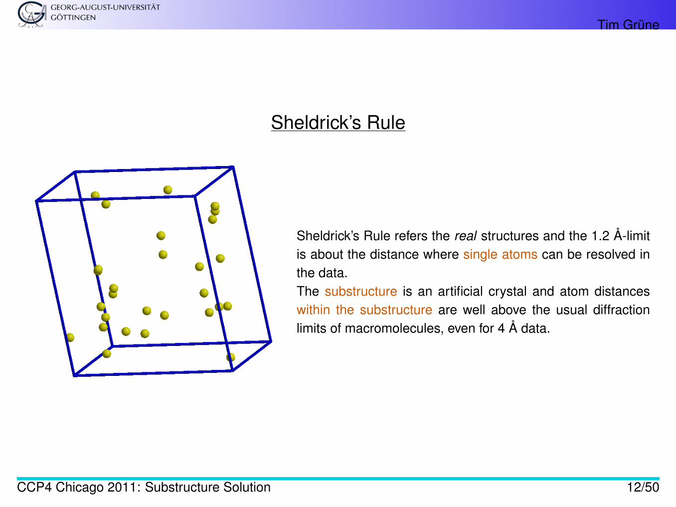
Sheldrick’s Rule
Sheldrick’s Rule refers the real structures and the 1.2 Å-limitis about the distance where single atoms can be resolved inthe data.The substructure is an artificial crystal and atom distanceswithin the substructure are well above the usual diffractionlimits of macromolecules, even for 4 Å data.
CCP4 Chicago 2011: Substructure Solution 12/50
Tim Grüne
Solving a Macromolecular Phase Problem with a Substructure
The substructure represents only a very small fraction of all atoms in the unit cell (one substructure atom per afew thousand atoms). Yet, knowing the coordinates of the substructure allows to solve the phase problem forthe full structure.
CCP4 Chicago 2011: Substructure Solution 13/50
Tim Grüne
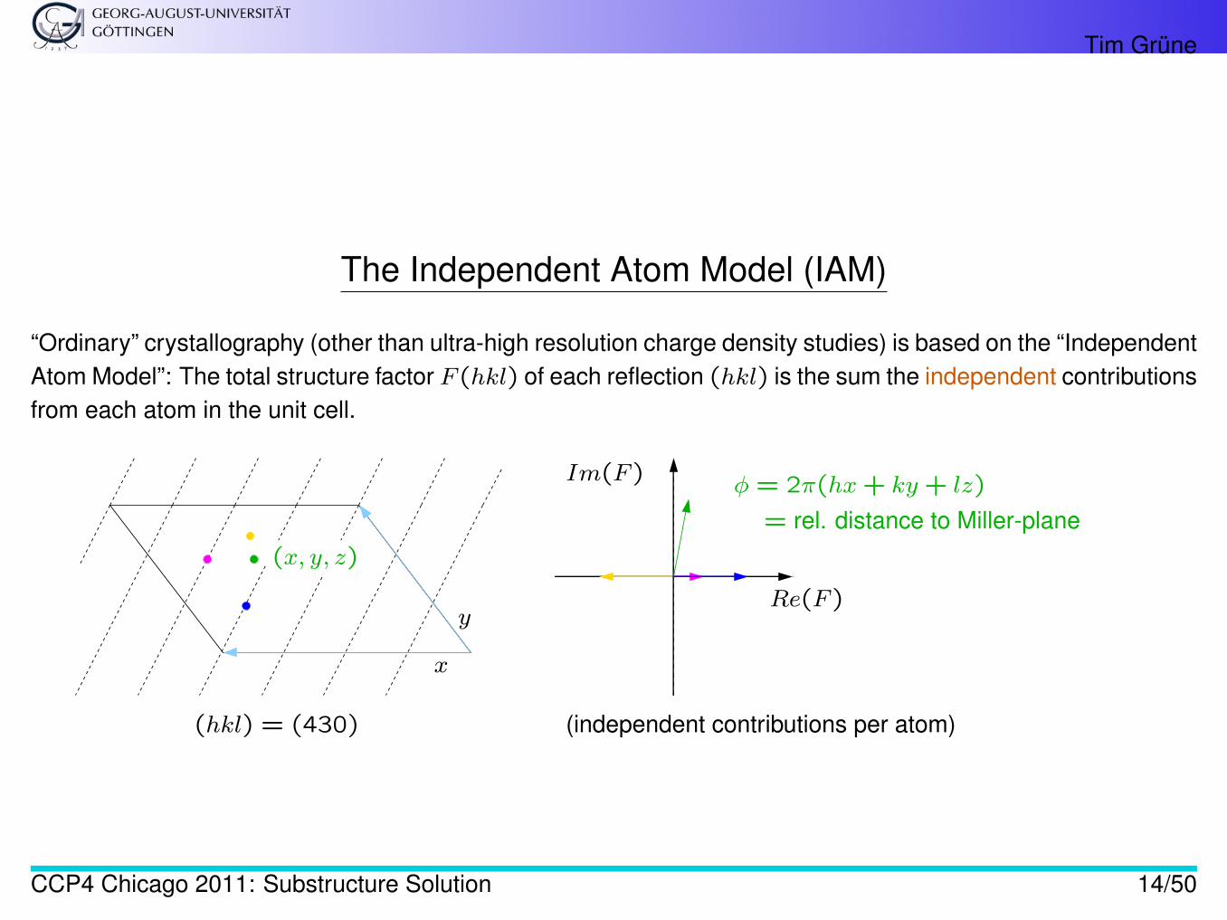
The Independent Atom Model (IAM)
“Ordinary” crystallography (other than ultra-high resolution charge density studies) is based on the “IndependentAtom Model”: The total structure factor F (hkl) of each reflection (hkl) is the sum the independent contributionsfrom each atom in the unit cell.
(x, y, z)
x
y
(hkl) = (430)
φ = 2π(hx+ ky + lz)
= rel. distance to Miller-plane
Re(F )
Im(F )
(independent contributions per atom)
CCP4 Chicago 2011: Substructure Solution 14/50
Tim Grüne
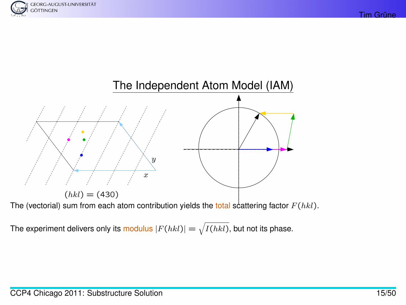
The Independent Atom Model (IAM)
x
y
(hkl) = (430)
The (vectorial) sum from each atom contribution yields the total scattering factor F (hkl).
The experiment delivers only its modulus |F (hkl)| =√I(hkl), but not its phase.
CCP4 Chicago 2011: Substructure Solution 15/50
Tim Grüne
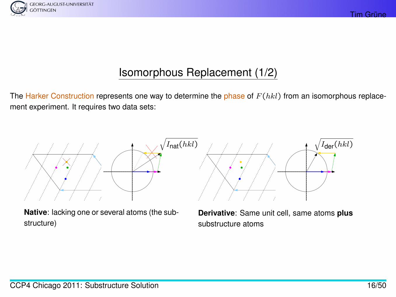
Isomorphous Replacement (1/2)
The Harker Construction represents one way to determine the phase of F (hkl) from an isomorphous replace-ment experiment. It requires two data sets:
√Inat(hkl)
√Ider(hkl)
Native: lacking one or several atoms (the sub-structure)
Derivative: Same unit cell, same atoms plussubstructure atoms
CCP4 Chicago 2011: Substructure Solution 16/50
Tim Grüne
Isomorphous Replacement (2/2)
The substructure coordinates can derived from the difference data set (√Ider(hkl)−
√Inat(hkl)).
The substructure phases φ(hkl) can be calculated from the substructure coordinates.
The phases of the native (or derivative) data set can be derived from
• measured native intensities Inat(hkl)
• measured derivative intensities Ider(hkl)
• calculated substructure structure factor F (hkl)
CCP4 Chicago 2011: Substructure Solution 17/50
Tim Grüne
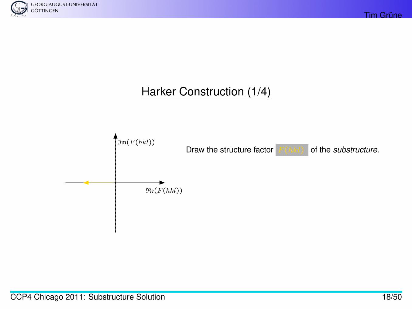
Harker Construction (1/4)
Im(F (hkl))
Re(F (hkl))
Draw the structure factor F (hkl) of the substructure.
CCP4 Chicago 2011: Substructure Solution 18/50
Tim Grüne
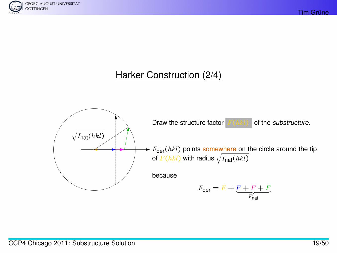
Harker Construction (2/4)
√Inat(hkl)
Draw the structure factor F (hkl) of the substructure.
Fder(hkl) points somewhere on the circle around the tipof F (hkl) with radius
√Inat(hkl)
because
Fder = F + F + F + F︸ ︷︷ ︸Fnat
CCP4 Chicago 2011: Substructure Solution 19/50
Tim Grüne
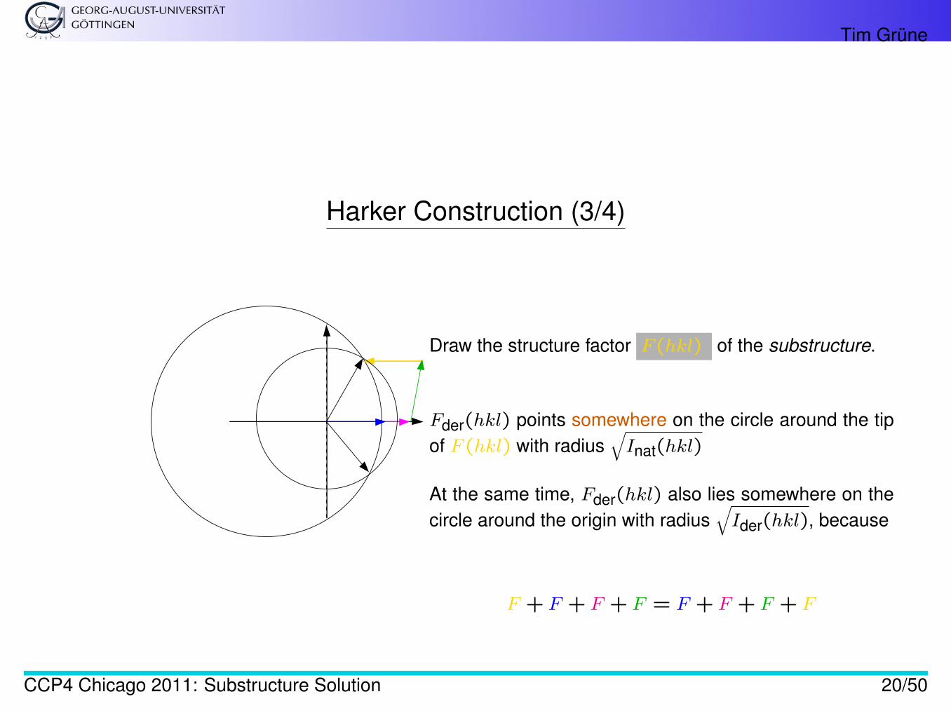
Harker Construction (3/4)
Draw the structure factor F (hkl) of the substructure.
Fder(hkl) points somewhere on the circle around the tipof F (hkl) with radius
√Inat(hkl)
At the same time, Fder(hkl) also lies somewhere on thecircle around the origin with radius
√Ider(hkl), because
F + F + F + F = F + F + F + F
CCP4 Chicago 2011: Substructure Solution 20/50
Tim Grüne
Harker Construction (4/4)
The two intersections of the two circles are the two possible structure factors Fder(hkl).
How to select the correct one:
MIR a second Harker construction with |Fder-2(hkl)| has exactly one of thetwo possibilities in common with the first Harker construction.
SIR the mean phase of the two possibilities serve as starting point for densitymodification, but if the substructure coordinates are centrosymmetric thetwo-fold ambiguity cannot always be resolved (this problem is specific toSIR).
CCP4 Chicago 2011: Substructure Solution 21/50
Tim Grüne
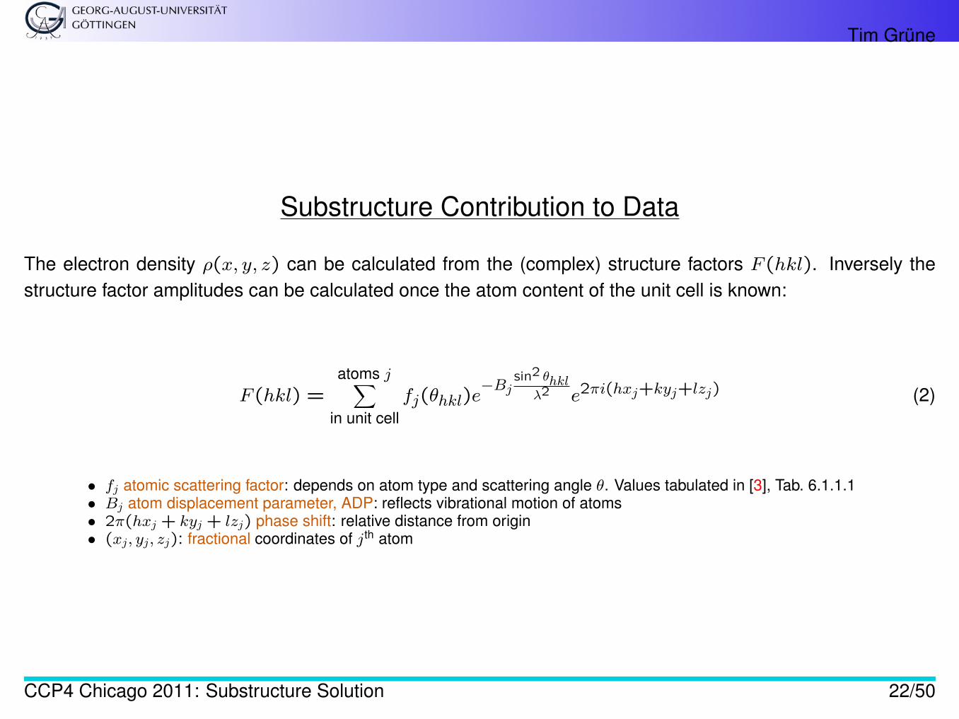
Substructure Contribution to Data
The electron density ρ(x, y, z) can be calculated from the (complex) structure factors F (hkl). Inversely thestructure factor amplitudes can be calculated once the atom content of the unit cell is known:
F (hkl) =atoms j∑
in unit cellfj(θhkl)e
−Bjsin2 θhkl
λ2 e2πi(hxj+kyj+lzj) (2)
• fj atomic scattering factor: depends on atom type and scattering angle θ. Values tabulated in [3], Tab. 6.1.1.1• Bj atom displacement parameter, ADP: reflects vibrational motion of atoms• 2π(hxj + kyj + lzj) phase shift: relative distance from origin• (xj, yj, zj): fractional coordinates of jth atom
CCP4 Chicago 2011: Substructure Solution 22/50
Tim Grüne
Extraction of Substructure Contribution
Experimental determination (i.e. other than by molecular replacement) of the contribution of the substructure tothe measured intensities is achieved by
• Anomalous Dispersion: Deviation from Friedel’s Law and comparison of|F (hkl)| with |F (h̄k̄l̄)|
• Isomorphous replacement: Changing the intensities without changing the unit cell and com-parison of
|Fnat| with |Fder|The alteration is usually achieved by the introduction of some heavy atom type into the crystal,either by soaking or by co-crystallisation.
CCP4 Chicago 2011: Substructure Solution 23/50
Tim Grüne
Anomalous Scattering
The atomic scattering factors fj(θ) describe the reaction of an atom’s electrons to X-rays.
They are different for each atom type (C, N, P,. . . ), but normally they are real numbers and do not vary signifi-cantly when changing the wavelength λ.
If, for one atom type, the wavelength λ matches the transition energy of one of the electron shells, anomalousscattering occurs.
This behaviour can be described by splitting fj(θ) into three parts:
fanomj = fj(θ) + f ′j(λ) + if ′′j (λ)
Near the transition energy, the latter two, f ′ and f ′′ vary strongly with the wavelength.
CCP4 Chicago 2011: Substructure Solution 24/50
Tim Grüne
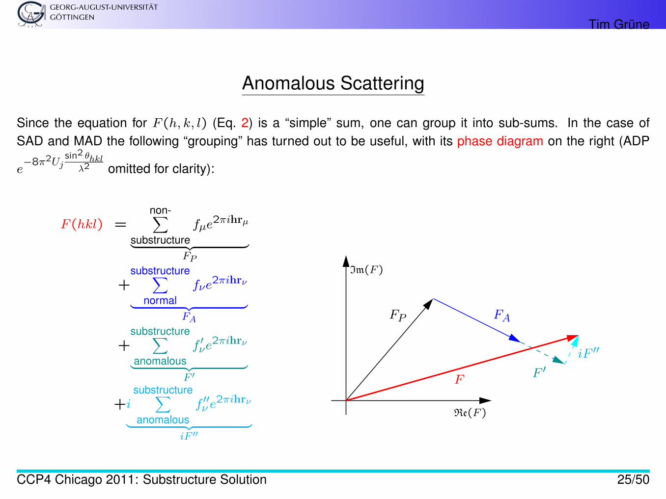
Anomalous Scattering
Since the equation for F (h, k, l) (Eq. 2) is a “simple” sum, one can group it into sub-sums. In the case ofSAD and MAD the following “grouping” has turned out to be useful, with its phase diagram on the right (ADP
e−8π2Uj
sin2 θhklλ2 omitted for clarity):
F (hkl) =non-∑
substructurefµe
2πihrµ
︸ ︷︷ ︸FP
+substructure∑
normalfνe
2πihrν
︸ ︷︷ ︸FA
+substructure∑anomalous
f ′νe2πihrν
︸ ︷︷ ︸F ′
+isubstructure∑anomalous
f ′′ν e2πihrν
︸ ︷︷ ︸iF ′′
Im(F )
Re(F )
FP FA
F ′iF ′′
F
CCP4 Chicago 2011: Substructure Solution 25/50
Tim Grüne
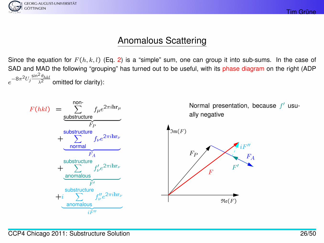
Anomalous Scattering
Since the equation for F (h, k, l) (Eq. 2) is a “simple” sum, one can group it into sub-sums. In the case ofSAD and MAD the following “grouping” has turned out to be useful, with its phase diagram on the right (ADP
e−8π2Uj
sin2 θhklλ2 omitted for clarity):
F (hkl) =non-∑
substructurefµe
2πihrµ
︸ ︷︷ ︸FP
+substructure∑
normalfνe
2πihrν
︸ ︷︷ ︸FA
+substructure∑anomalous
f ′νe2πihrν
︸ ︷︷ ︸F ′
+isubstructure∑anomalous
f ′′ν e2πihrν
︸ ︷︷ ︸iF ′′
Im(F )
Re(F )
FP FA
F ′
iF ′′
F
Normal presentation, because f ′ usu-ally negative
CCP4 Chicago 2011: Substructure Solution 26/50
Tim Grüne
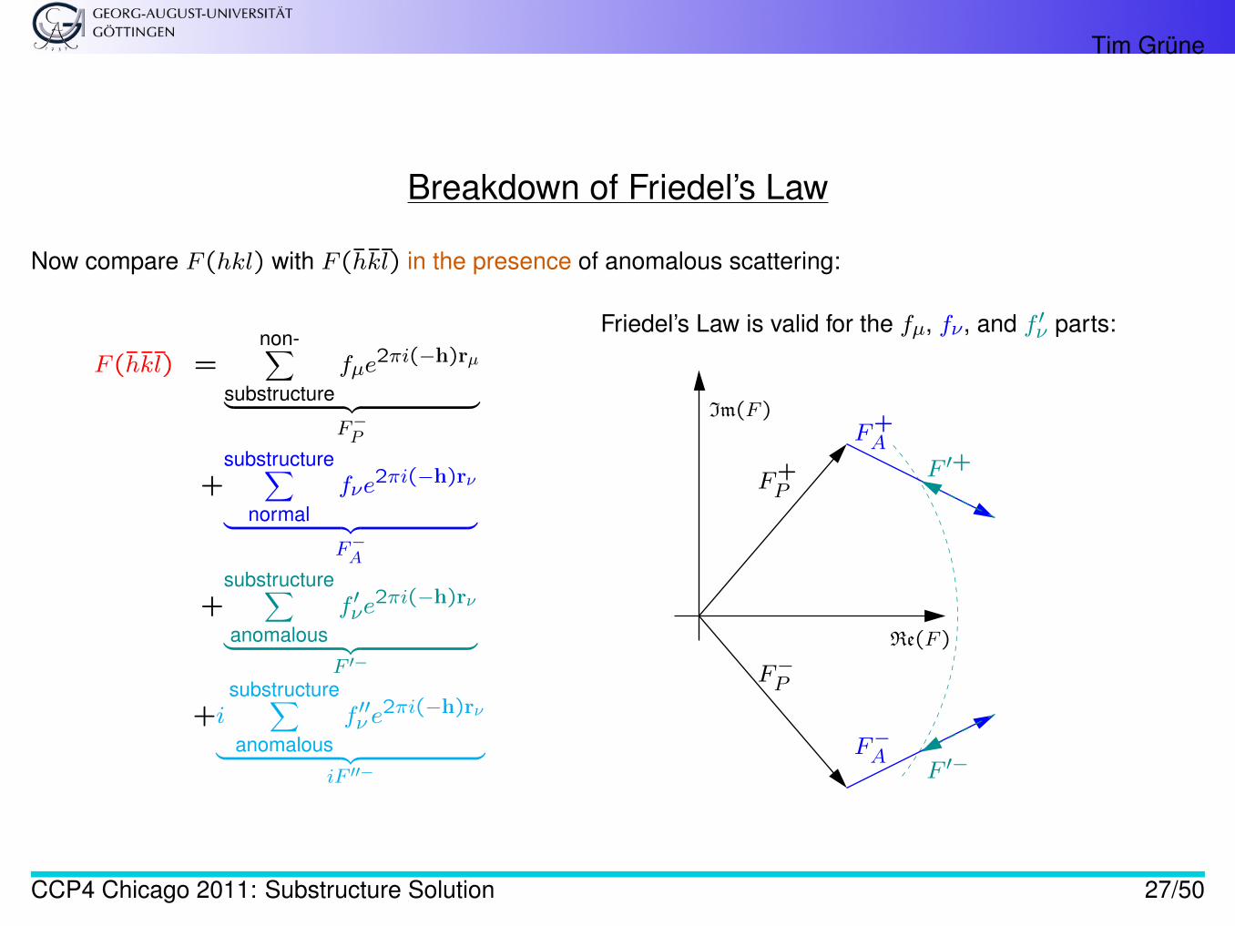
Breakdown of Friedel’s Law
Now compare F (hkl) with F (h̄k̄l̄) in the presence of anomalous scattering:
F (h̄k̄l̄) =non-∑
substructurefµe
2πi(−h)rµ
︸ ︷︷ ︸F−P
+substructure∑
normalfνe
2πi(−h)rν
︸ ︷︷ ︸F−A
+substructure∑anomalous
f ′νe2πi(−h)rν
︸ ︷︷ ︸F ′−
+isubstructure∑anomalous
f ′′ν e2πi(−h)rν
︸ ︷︷ ︸iF ′′−
Im(F )
Re(F )
F+P
F+A
F ′+
Friedel’s Law is valid for the fµ, fν, and f ′ν parts:
F−P
F−AF ′−
CCP4 Chicago 2011: Substructure Solution 27/50
Tim Grüne
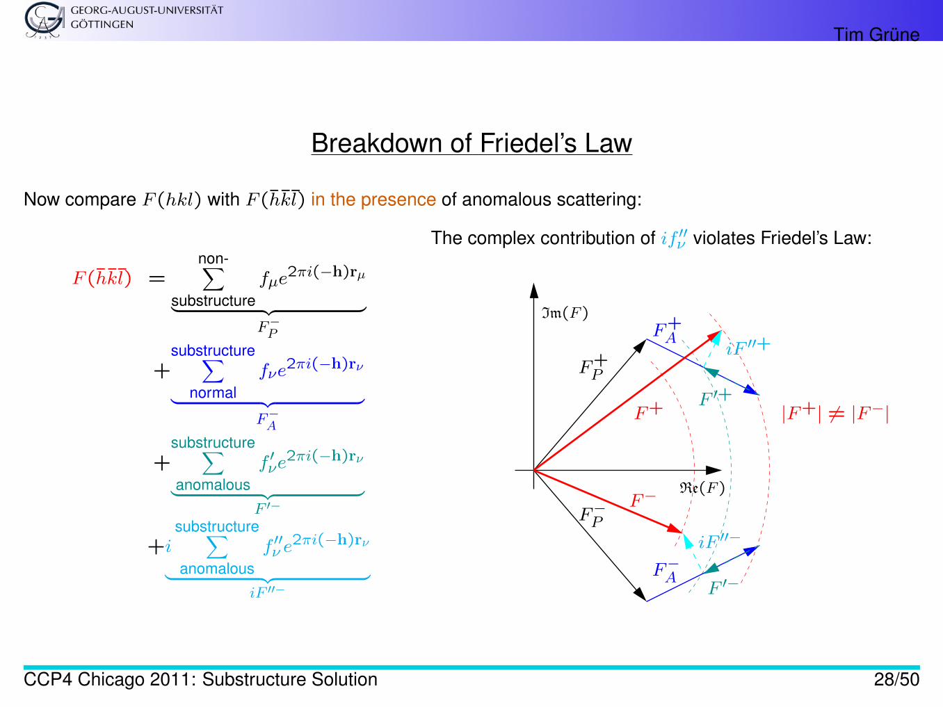
Breakdown of Friedel’s Law
Now compare F (hkl) with F (h̄k̄l̄) in the presence of anomalous scattering:
F (h̄k̄l̄) =non-∑
substructurefµe
2πi(−h)rµ
︸ ︷︷ ︸F−P
+substructure∑
normalfνe
2πi(−h)rν
︸ ︷︷ ︸F−A
+substructure∑anomalous
f ′νe2πi(−h)rν
︸ ︷︷ ︸F ′−
+isubstructure∑anomalous
f ′′ν e2πi(−h)rν
︸ ︷︷ ︸iF ′′−
Im(F )
Re(F )
F+P
F+A
F ′+
iF ′′+
F+
The complex contribution of if ′′ν violates Friedel’s Law:
F−P
F−AF ′−
iF ′′−
F−
|F+| 6= |F−|
CCP4 Chicago 2011: Substructure Solution 28/50
Tim Grüne
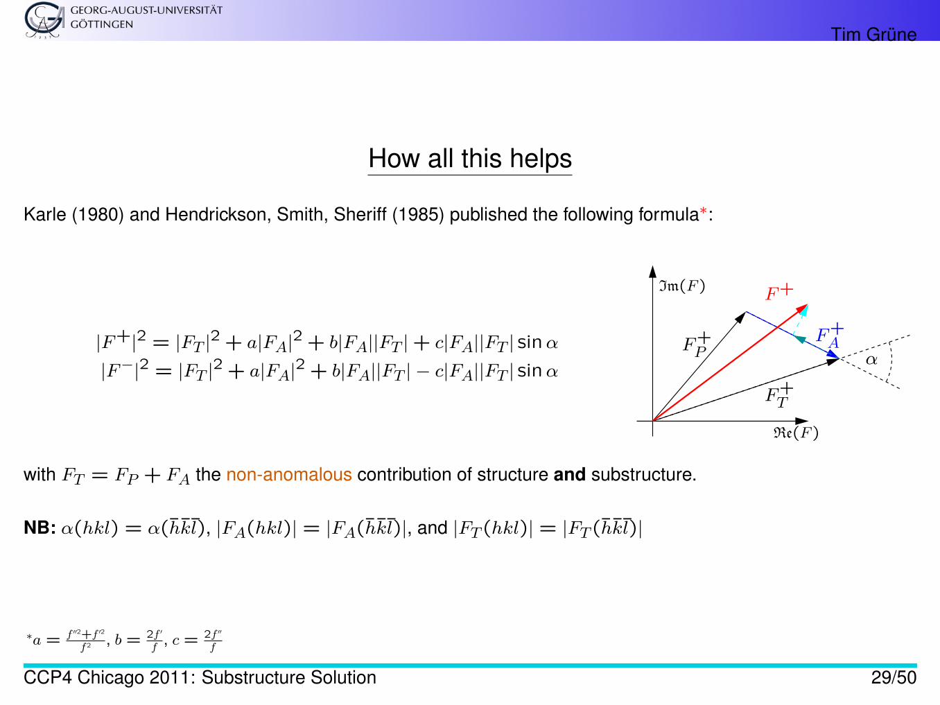
How all this helps
Karle (1980) and Hendrickson, Smith, Sheriff (1985) published the following formula∗:
|F+|2 = |FT |2 + a|FA|2 + b|FA||FT |+ c|FA||FT | sinα
|F−|2 = |FT |2 + a|FA|2 + b|FA||FT | − c|FA||FT | sinα
Im(F )
Re(F )
α
F+T
F+AF+
P
F+
with FT = FP + FA the non-anomalous contribution of structure and substructure.
NB: α(hkl) = α(h̄k̄l̄), |FA(hkl)| = |FA(h̄k̄l̄)|, and |FT (hkl)| = |FT (h̄k̄l̄)|
∗a = f ′′2+f ′2
f 2 , b = 2f ′
f, c = 2f ′′
f
CCP4 Chicago 2011: Substructure Solution 29/50
Tim Grüne
Combining Theory and Experiment
The diffraction experiment measures the Bijvoet pairs |F+| and |F−| for many reflections.
In order to “simulate” a small-molecule experiment for the substructure, we must know |FA|.
With the approximation 12(|F+|+ |F−|) ≈ |FT | the difference between the two equations above yields
|F+| − |F−| ≈ c|FA| sinα
CCP4 Chicago 2011: Substructure Solution 30/50
Tim Grüne
Status Quo – A Summary
• Our experiment measures |F+| =√I(hkl) and |F−| =
√I(h̄k̄l̄).
• We are looking for (an estimate) of |FA| for all measured reflections.– These |FA| mimic a small-molecule data set from the substructure alone.– The small-molecule data set can be solved with direct methods, even at moderate resolution.
• With the help of Karle and Hendrickson, Smith, Sheriff, we already derived
|F+| − |F−| ≈ c|FA| sinα
We are nearly there!
CCP4 Chicago 2011: Substructure Solution 31/50
Tim Grüne
The Factor c
Before we know |FA|, we must “get rid of” c and sinα.
c = 2f ′′(λ)f(θ(hkl)) can be calculated for every reflection provided f ′′(λ).
During a MAD experiment, f ′′(λ) is usually measured by a fluorescence scan.
To avoid the dependency on f ′′(λ), the program shelxd [1] uses normalised structure factor amplitudes|E(hkl)| instead of |F (hkl)|, which are very common for small-molecule programs.
CCP4 Chicago 2011: Substructure Solution 32/50
Tim Grüne
The Angle α
In the case of MAD, multi-wavelength anomalous dispersion, we can calculate sinα because there is oneequation for each wavelength.
In the case of SAD, the program shelxd approximates |FA| sin(α) ≈ |FA|.
Why is this justified?
Bijvoet pairs with a strong anomalous difference (∣∣∣|F+| − |F−|
∣∣∣) have greater impact in direct methods. Thedifference is large, however, when α is close to 90◦ or 270◦, i.e. when sin(α) ≈ ±1. This coarse approximationhas proven good enough to solve hundreds or thousands of structures with shelxd.
CCP4 Chicago 2011: Substructure Solution 33/50

Tim Grüne
The Angle α
In the case of MAD, multi-wavelength anomalous dispersion, we can calculate sinα because there is oneequation for each wavelength.
In the case of SAD, the program shelxd approximates |FA| sin(α) ≈ |FA|.
Why is this justified?
Bijvoet pairs with a strong anomalous difference (∣∣∣|F+| − |F−|
∣∣∣) have greater impact in direct methods. Thedifference is large, however, when α is close to 90◦ or 270◦, i.e. when sin(α) ≈ ±1. This coarse approximationhas proven good enough to solve hundreds or thousands of structures with shelxd.
CCP4 Chicago 2011: Substructure Solution 34/50
Tim Grüne
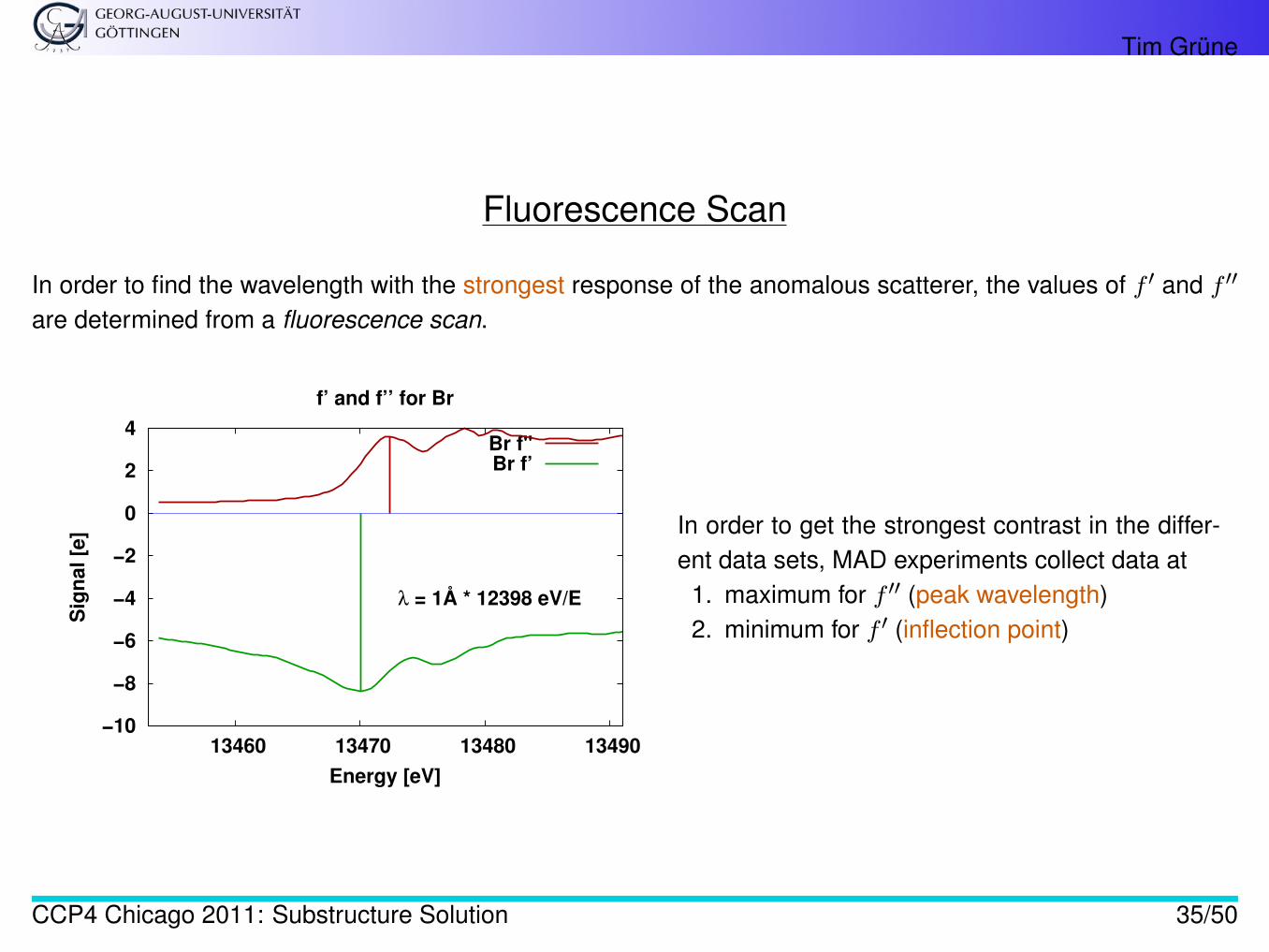
Fluorescence Scan
In order to find the wavelength with the strongest response of the anomalous scatterer, the values of f ′ and f ′′
are determined from a fluorescence scan.
−10
−8
−6
−4
−2
0
2
4
13460 13470 13480 13490
Sig
nal [
e]
Energy [eV]
f’ and f’’ for Br
λ = 1Å * 12398 eV/E
Br f"Br f’
In order to get the strongest contrast in the differ-ent data sets, MAD experiments collect data at
1. maximum for f ′′ (peak wavelength)2. minimum for f ′ (inflection point)
CCP4 Chicago 2011: Substructure Solution 35/50
Tim Grüne
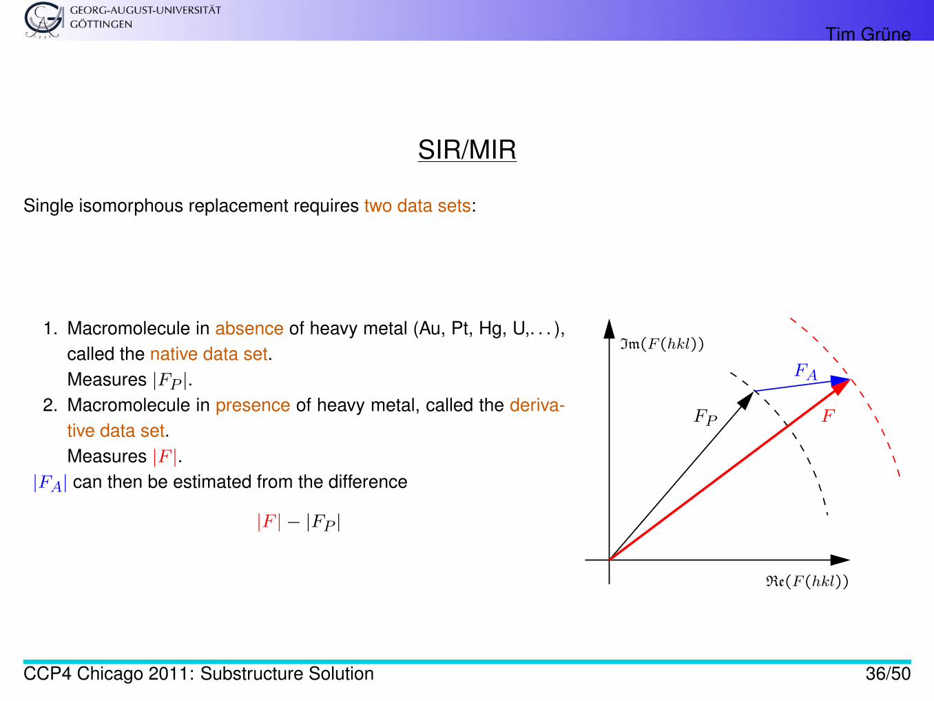
SIR/MIR
Single isomorphous replacement requires two data sets:
1. Macromolecule in absence of heavy metal (Au, Pt, Hg, U,. . . ),called the native data set.Measures |FP |.
2. Macromolecule in presence of heavy metal, called the deriva-tive data set.Measures |F |.
|FA| can then be estimated from the difference
|F | − |FP |
Im(F (hkl))
Re(F (hkl))
F
FA
FP
CCP4 Chicago 2011: Substructure Solution 36/50
Tim Grüne
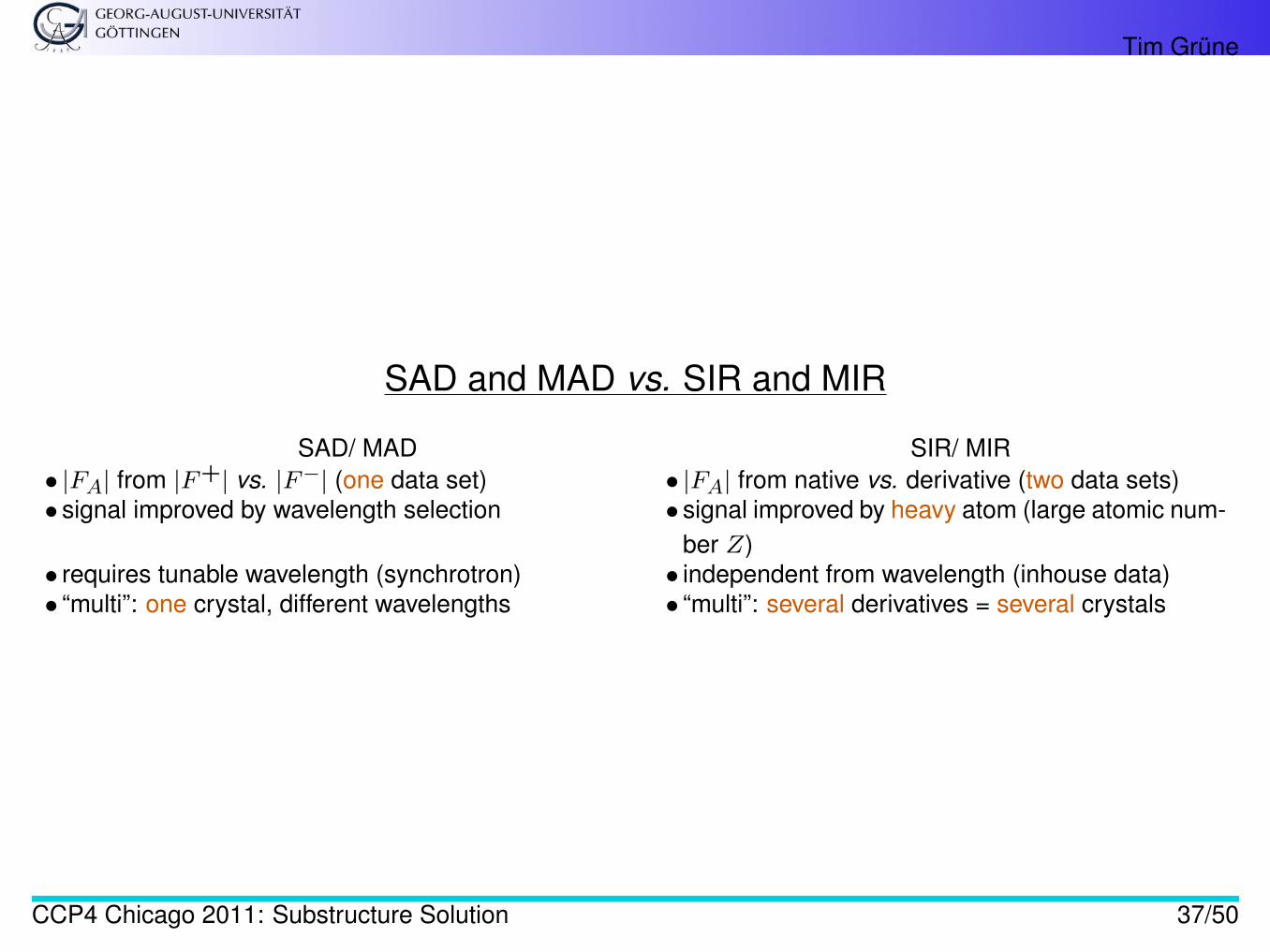
SAD and MAD vs. SIR and MIR
SAD/ MAD SIR/ MIR• |FA| from |F+| vs. |F−| (one data set) • |FA| from native vs. derivative (two data sets)• signal improved by wavelength selection • signal improved by heavy atom (large atomic num-
ber Z)• requires tunable wavelength (synchrotron) • independent from wavelength (inhouse data)• “multi”: one crystal, different wavelengths • “multi”: several derivatives = several crystals
CCP4 Chicago 2011: Substructure Solution 37/50
Tim Grüne
SIRAS (1/2)
Isomorphous replacement is hardly used for phasing anymore:
• Incorporation of heavy atom into crystal often alters the unit cell⇒ non-isomorphismbetween native and derivative ruins usability of data sets• Heavy atom in structure⇒ go to synchrotron and try MAD instead of SIR/MIR
CCP4 Chicago 2011: Substructure Solution 38/50
Tim Grüne
SIRAS (2/2)
However, one often has a high-resolution data set from a native crystal and one (lower resolution) data set withanomalous signal.
They can be combined into a SIRAS experiment:
• Anomalous data set: SAD• Anomalous data set as derivative vs. native: SIR
These are two independent sources of phase information and usually work better than either alone.
CCP4 Chicago 2011: Substructure Solution 39/50
Tim Grüne
|FA|: Substructure Solution with Direct Methods
CCP4 Chicago 2011: Substructure Solution 40/50
Tim Grüne
Direct Methods
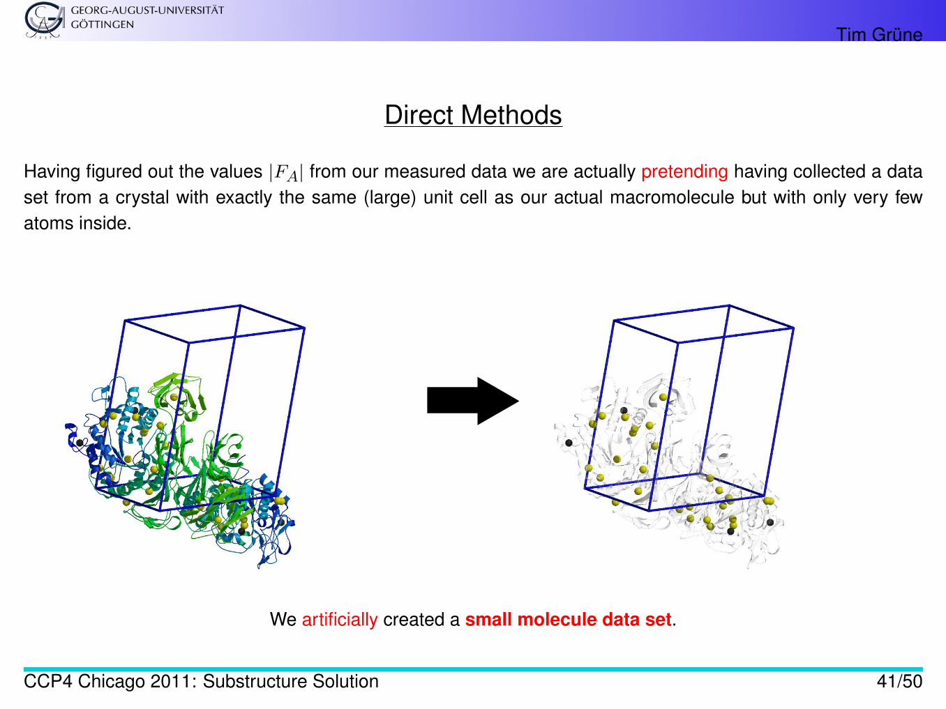
Having figured out the values |FA| from our measured data we are actually pretending having collected a dataset from a crystal with exactly the same (large) unit cell as our actual macromolecule but with only very fewatoms inside.
We artificially created a small molecule data set.
CCP4 Chicago 2011: Substructure Solution 41/50
Tim Grüne
Normalised Structure Factors
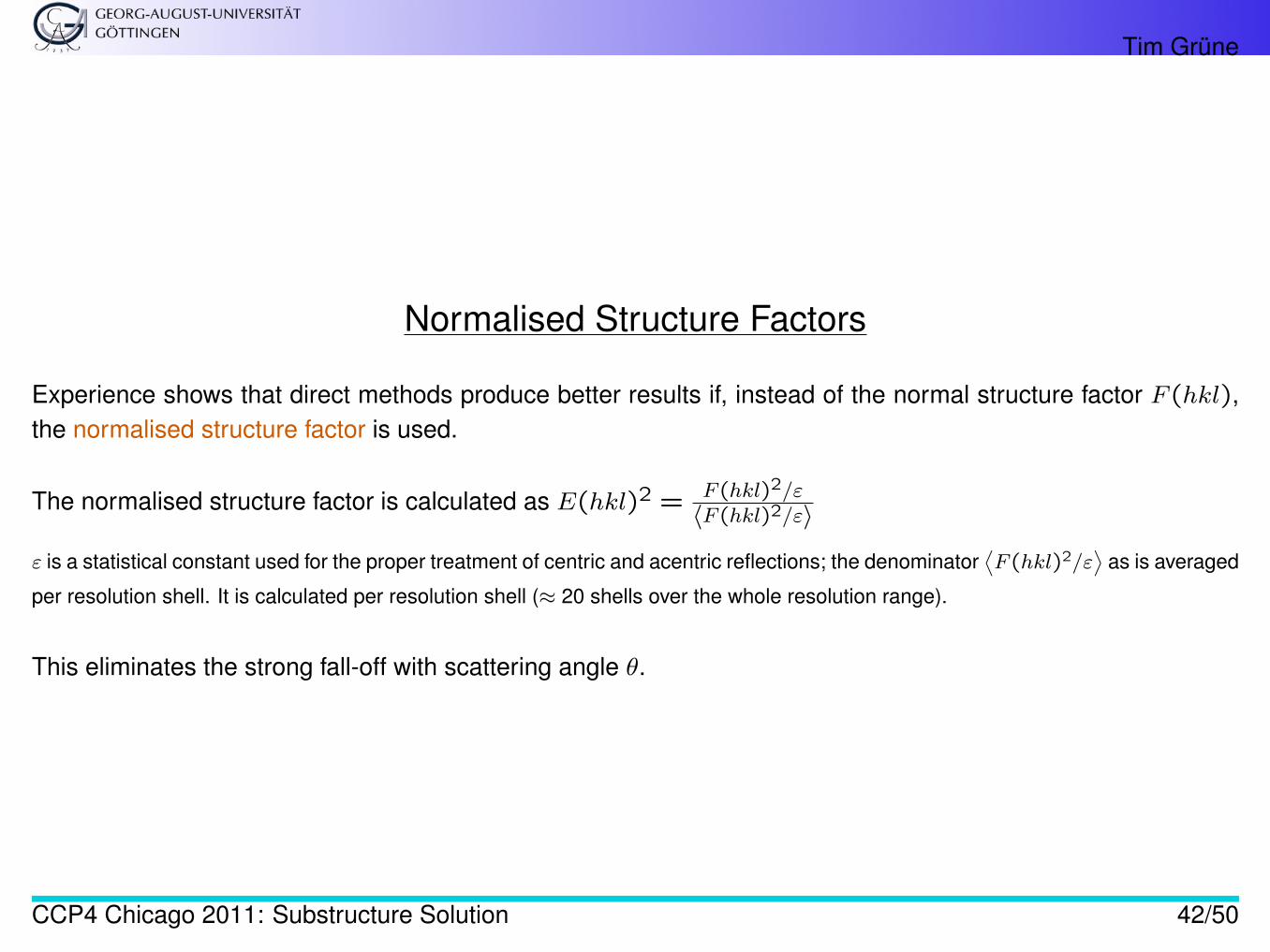
Experience shows that direct methods produce better results if, instead of the normal structure factor F (hkl),the normalised structure factor is used.
The normalised structure factor is calculated as E(hkl)2 = F (hkl)2/ε
〈F (hkl)2/ε〉
ε is a statistical constant used for the proper treatment of centric and acentric reflections; the denominator⟨F (hkl)2/ε
⟩as is averaged
per resolution shell. It is calculated per resolution shell (≈ 20 shells over the whole resolution range).
This eliminates the strong fall-off with scattering angle θ.
CCP4 Chicago 2011: Substructure Solution 42/50
Tim Grüne
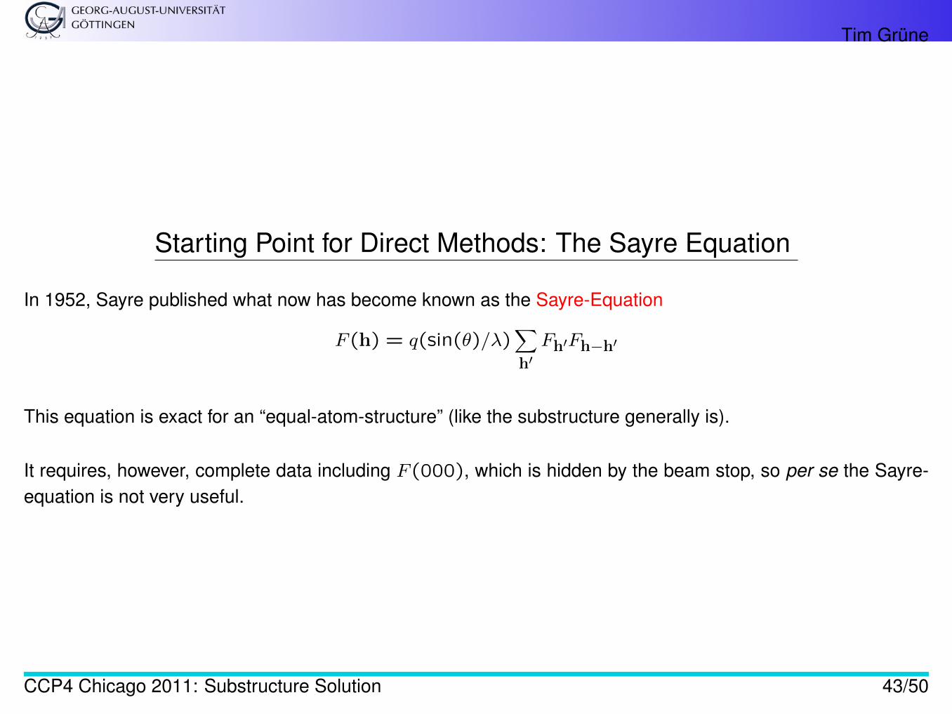
Starting Point for Direct Methods: The Sayre Equation
In 1952, Sayre published what now has become known as the Sayre-Equation
F (h) = q(sin(θ)/λ)∑h′Fh′Fh−h′
This equation is exact for an “equal-atom-structure” (like the substructure generally is).
It requires, however, complete data including F (000), which is hidden by the beam stop, so per se the Sayre-equation is not very useful.
CCP4 Chicago 2011: Substructure Solution 43/50
Tim Grüne
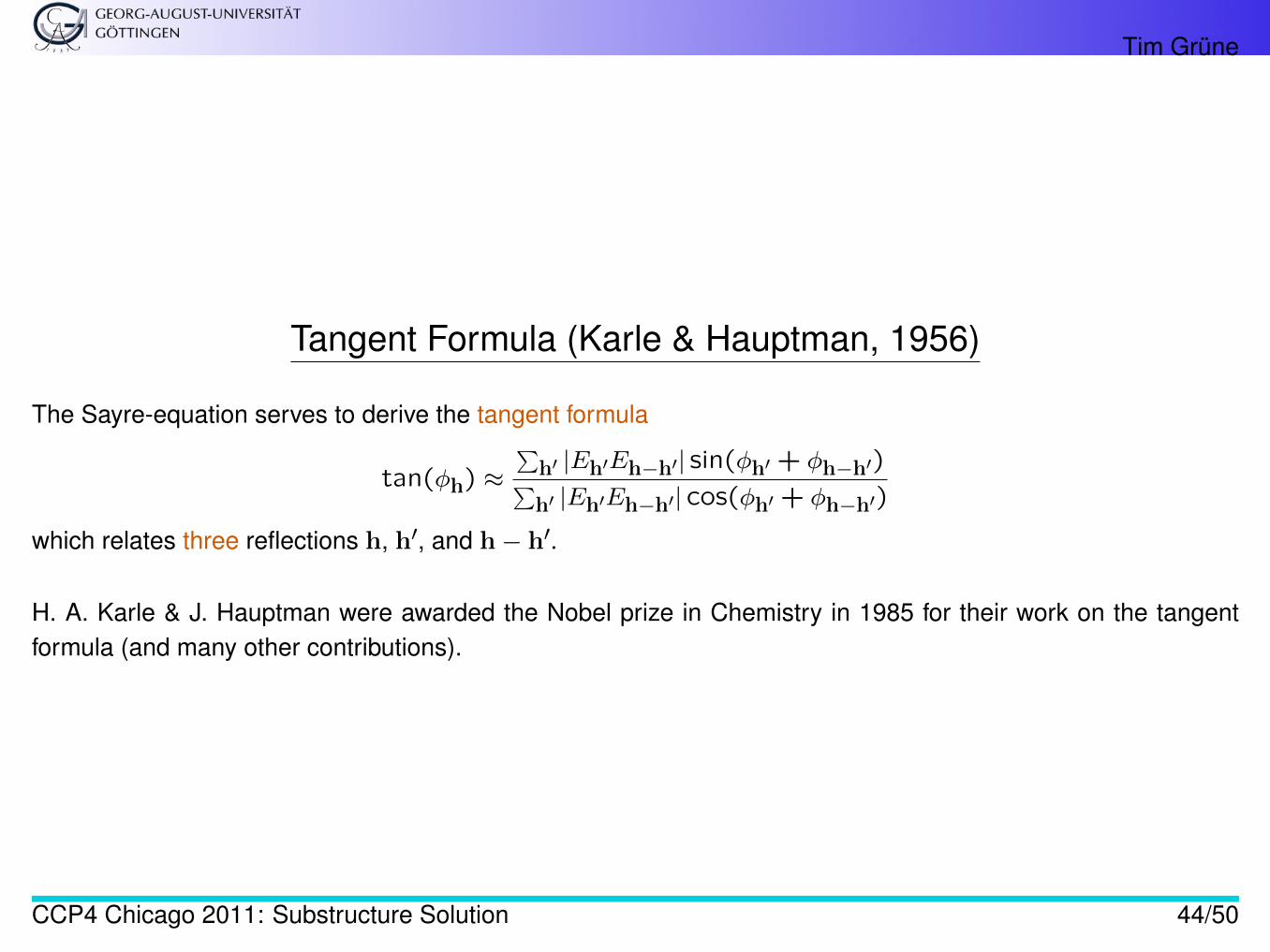
Tangent Formula (Karle & Hauptman, 1956)
The Sayre-equation serves to derive the tangent formula
tan(φh) ≈∑
h′ |Eh′Eh−h′| sin(φh′ + φh−h′)∑h′ |Eh′Eh−h′| cos(φh′ + φh−h′)
which relates three reflections h, h′, and h− h′.
H. A. Karle & J. Hauptman were awarded the Nobel prize in Chemistry in 1985 for their work on the tangentformula (and many other contributions).
CCP4 Chicago 2011: Substructure Solution 44/50
Tim Grüne
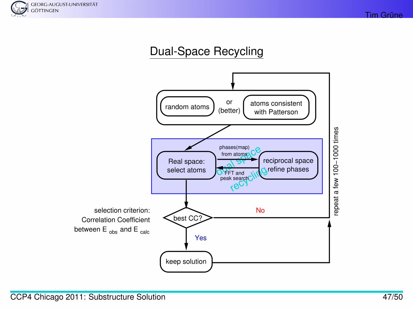
Solving the Substructure
Direct methods (and in particular shelxd) do the following:
1. Assign a random phase to each reflection. They will not fulfil the tangent formula.2. Refine the phases using |FA| (or rather |EA|) to improve their fit to the tangent formula3. Calculate a map, pick the strong peaks (as putative substructure)4. Calculate phases from the peak coordinates and return to step 2.
CCP4 Chicago 2011: Substructure Solution 45/50
Tim Grüne
Solving the Substructure
Steps 1-4 are repeated many times, each time with a new set of random phases.
Every such attempt is evaluated and the best attempt is kept as solution for the substructure.
The substructure is thus found by chance. It works even if the data quality is only medium — but may requiremore trials.
The cycling between steps 2-3, i.e. phase refinement in reciprocal space vs. peak picking in direct space, iscalled dual space recycling [4, section 16.1]
CCP4 Chicago 2011: Substructure Solution 46/50
Tim Grüne
Dual-Space Recycling
dual space
recycling
Real space:
select atoms
reciprocal space
refine phases
random atomsatoms consistent
with Patterson
repeat a few
100−
1000 tim
es
Yes
No
FFT andpeak search
from atoms
phases(map)
keep solution
between E obs and E calc
selection criterion:
Correlation Coefficient
or
(better)
best CC?
CCP4 Chicago 2011: Substructure Solution 47/50
Tim Grüne
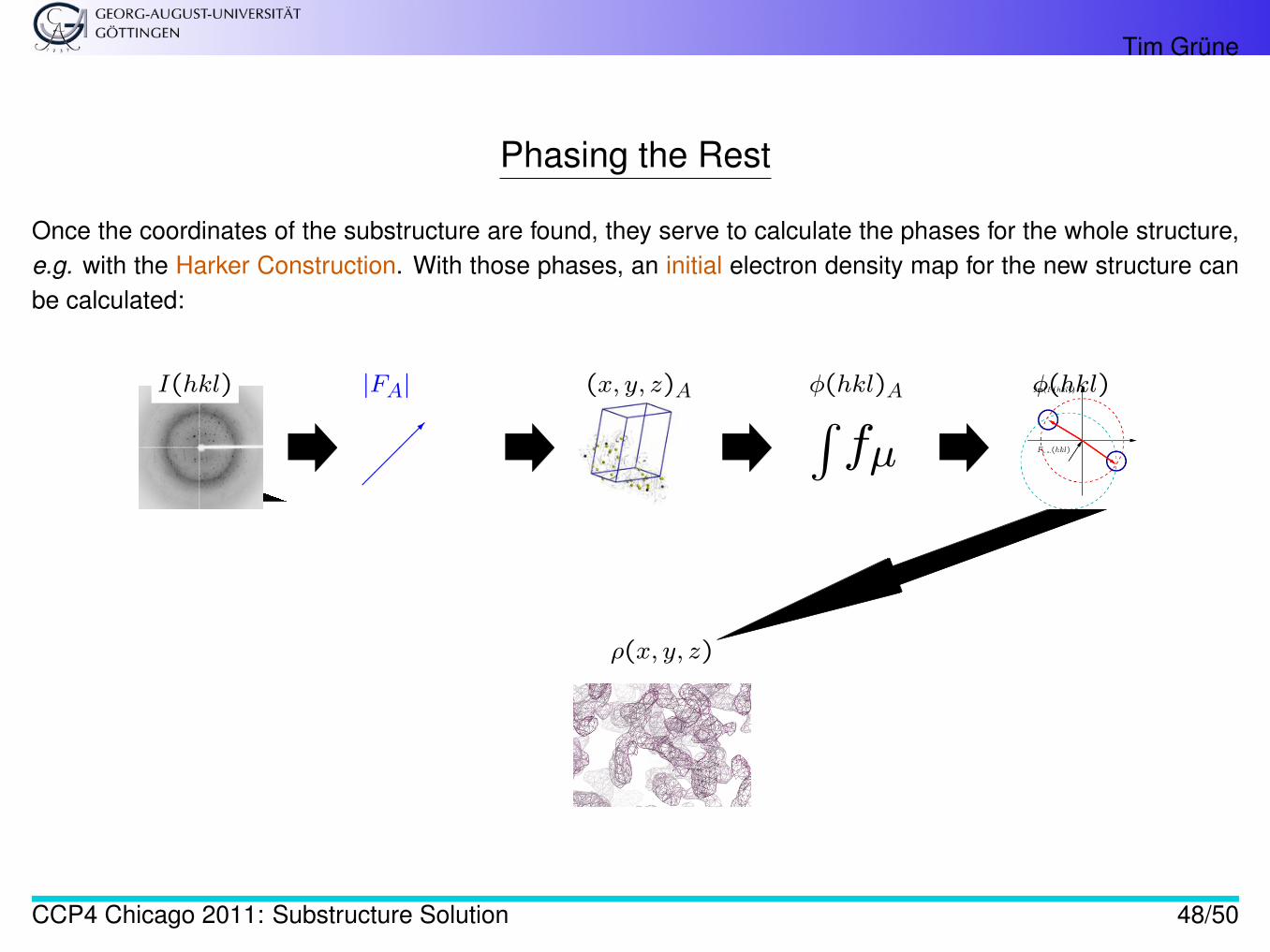
Phasing the Rest
Once the coordinates of the substructure are found, they serve to calculate the phases for the whole structure,e.g. with the Harker Construction. With those phases, an initial electron density map for the new structure canbe calculated:
I(hkl)
������
|FA| (x, y, z)A ∫fµ
φ(hkl)A φ(hkl)
ρ(x, y, z)
CCP4 Chicago 2011: Substructure Solution 48/50

Tim Grüne
Phasing the Rest
. . . this is the field of density modification and not part of this presentation. . .
CCP4 Chicago 2011: Substructure Solution 49/50
Tim Grüne
References
1. G. M. Sheldrick, A short history of SHELX, Acta Crystallogr. (2008), A64, pp.112–1332. R. J. Morris & G. Bricogne, Sheldrick’s 1.2Å rule and beyond, Acta Crystallogr. (2003), D59, pp. 615–6173. E. Prince (ed.), International Tables for Crystallography, Vol. C, Union of Crystallography4. M. G. Rossmann & E. Arnold (eds.), International Tables for Crystallography, Vol. F, Union of Crystallogra-
phy
CCP4 Chicago 2011: Substructure Solution 50/50