ccd camera ik-53v/ik-52v
TRANSCRIPT
CCD CAMERA
IK-53V/IK-52V
OPERATING GUIDE
FCC Statement
This device complies with Part 15 of the FCC Rules. Operation is subject to the following twoconditions: (1) This device may not cause harmful interference, and (2) this device must ac-cept any interference received, including interference that may cause undesired operation.
INFORMATION
This equipment has been tested and found to comply with the limits for a Class A digital device,pursuant to Part 15 of the FCC Rules. These limits are designed to provide reasonable protectionagainst harmful interference when the equipment is operated in a commercial environment.This equipment generates, uses, and can radiate radio frequency energy and, if not installedand used in accordance with the instruction manual, may cause harmful interference to radiocommunications. Operation of this equipment in a residential area is likely to cause harmfulinterference in which case the user will be required to correct the interference at his own ex-pense.
USER-INSTALLER CAUTION: Your authority to operate this FCC verified equipment could bevoided if you make changes or modifications not expressly approved by the party responsible forcompliance to Part 15 of the FCC rules.
This Class A digital apparatus complies with Canadian ICES-003.
Cet appareil numérique de la classe A est comforme à la norme NMB-003 du Canada.
1
CONTENTS
1. GENERAL ....................................................................................................................2
2. CAMERA PARTS AND FUNCTIONS ......................................................................... 3
3. CONNECTIONS ......................................................................................................... 5
4. SETTING .....................................................................................................................6
4-1. Video Scanning Modes ......................................................................................6
4-2. Electronic Shutter ...............................................................................................8
4-3. Reset Restart ...................................................................................................... 9
4-4. External Trigger Mode ..................................................................................... 10
5. Input Output Signal Specifications ....................................................................... 15
6. CCD Output Waveform Timing Chart ................................................................... 17
7. EXTERIOR VIEW ...................................................................................................... 18
8. SPECIFICATIONS ..................................................................................................... 19
2
1.GENERAL
The IK-53V/IK-52V is a monochrome video camera using a solid image sensor CCD (ChargedCoupled Device).
High Picture Quality
The VGA-applicable CCD of 330,000 pixels provides a fine picture equivalent to VGA. Thesquare pixel CCD eliminates the necessity of conversion to aspect ratio when processing im-ages.
Various Modes Setting
The following modes can be set by the switches on the rear panel.• Gain: Fixed/manual adjustment (0 to +18 dB)• Partial scanning Function• Synchronized input/output (HD/VD)• 75Ω terminal (at external synchronous input)• Shutter function: Normal/external trigger shutter• Shutter speed
External Synchronization
External HD/VD signals are analyzed and the synchronization mode is automatically selectedto match the input signals.
Internal Synchronizing Signal Output
HD and VD signals can be outputted from the 12-pin connector by changing the switch posi-tion on the rear panel.
Electric Shutter Speed
A variety of shutter speeds (1/100 to 1/100,000 sec) is provided to permit choice suitable forshooting conditions.
External Trigger Function
A trigger input provides one still image. This function exactly captures a subject moving at ahigh speed.
Partial Scanning Function
The number of effective video output lines is limited to provide a high frame rate video outputsuitable for speedy image processing.
Cabinet Fixing
The cabinet fixing screw hole is provided below the front panel which includes the CCD datumlevel. Fix the camera using this screw hole to minimize shifts in the optical axis.
3
2.CAMERA PARTS AND FUNCTIONS
Top/Bottom/Front Side
1 2
[Top]
3
4[Bottom]
5
[Front]
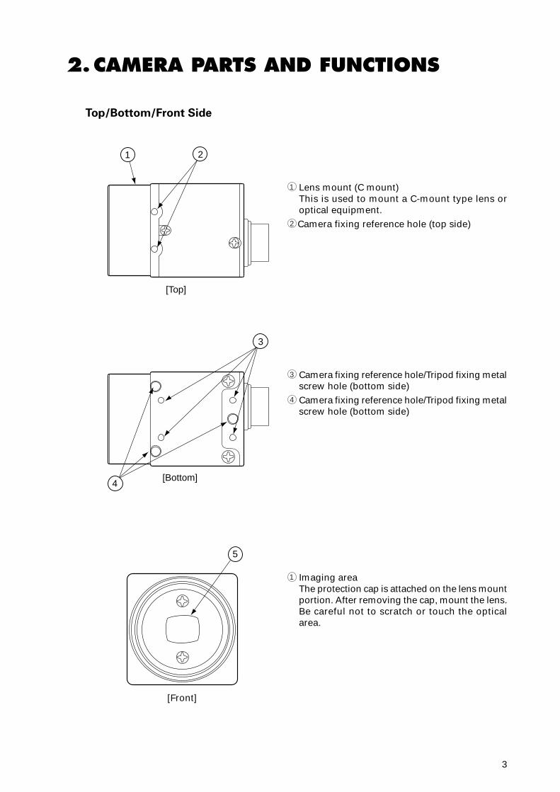
1 Lens mount (C mount)This is used to mount a C-mount type lens oroptical equipment.
2 Camera fixing reference hole (top side)
3 Camera fixing reference hole/Tripod fixing metalscrew hole (bottom side)
4 Camera fixing reference hole/Tripod fixing metalscrew hole (bottom side)
1 Imaging areaThe protection cap is attached on the lens mountportion. After removing the cap, mount the lens.Be careful not to scratch or touch the opticalarea.
4
Rear Side
1 ON2
34567890
ON OFF
EXT INTHD/VD75Ω
SHT
TRG
M.G
MIN MAX
M GAIN
VIDEO OUTDC IN/SYNC
P.S
4
1
2 34
5
1
2
3
4
5
Enlarged
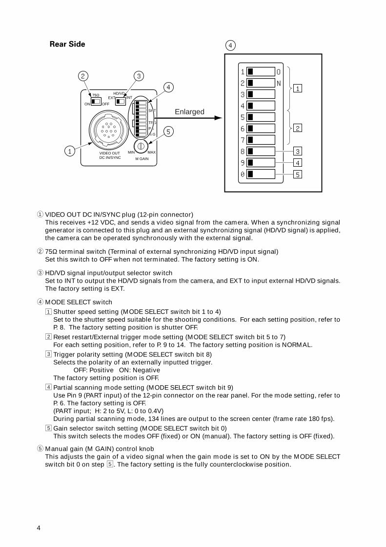
1 VIDEO OUT DC IN/SYNC plug (12-pin connector)This receives +12 VDC, and sends a video signal from the camera. When a synchronizing signalgenerator is connected to this plug and an external synchronizing signal (HD/VD signal) is applied,the camera can be operated synchronously with the external signal.
2 75Ω terminal switch (Terminal of external synchronizing HD/VD input signal)Set this switch to OFF when not terminated. The factory setting is ON.
3 HD/VD signal input/output selector switchSet to INT to output the HD/VD signals from the camera, and EXT to input external HD/VD signals.The factory setting is EXT.
4 MODE SELECT switch1 Shutter speed setting (MODE SELECT switch bit 1 to 4)
Set to the shutter speed suitable for the shooting conditions. For each setting position, refer toP. 8. The factory setting position is shutter OFF.
2 Reset restart/External trigger mode setting (MODE SELECT switch bit 5 to 7)For each setting position, refer to P. 9 to 14. The factory setting position is NORMAL.
3 Trigger polarity setting (MODE SELECT switch bit 8)Selects the polarity of an externally inputted trigger.
OFF: Positive ON: NegativeThe factory setting position is OFF.
4 Partial scanning mode setting (MODE SELECT switch bit 9)Use Pin 9 (PART input) of the 12-pin connector on the rear panel. For the mode setting, refer toP. 6. The factory setting is OFF.(PART input; H: 2 to 5V, L: 0 to 0.4V)During partial scanning mode, 134 lines are output to the screen center (frame rate 180 fps).
5 Gain selector switch setting (MODE SELECT switch bit 0)This switch selects the modes OFF (fixed) or ON (manual). The factory setting is OFF (fixed).
5 Manual gain (M GAIN) control knobThis adjusts the gain of a video signal when the gain mode is set to ON by the MODE SELECTswitch bit 0 on step 5 . The factory setting is the fully counterclockwise position.
5
3.CONNECTIONS
Standard Connection
Camera Cable(optional)
Image processorLens
IK-53VIK-52V
12
3
45
6
7
89
10
11 12
Cautions on Connection
• When connecting the camera cables, be sure to turn off the camera and the other equipmentconnected.
• When using another lens, the best camera performance of this camera may not be obtained.(For example, low resolution may occur, and flare, ghost or shading may occur)
• Use the DC power source described below.• Power supply voltage: +10.5V to +15V• Current rating: More than 830 mA• Ripple voltage: Less than 50 mV(p–p)
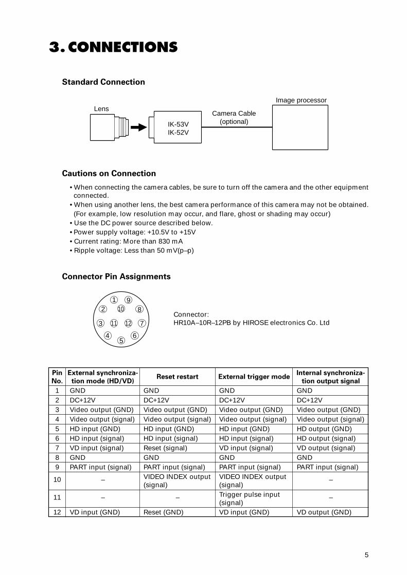
Connector Pin Assignments
Pin
No.
123456789
10
11
12
External synchroniza-
tion mode (HD/VD)
GNDDC+12VVideo output (GND)Video output (signal)HD input (GND)HD input (signal)VD input (signal)GNDPART input (signal)
–
–
VD input (GND)
Reset restart
GNDDC+12VVideo output (GND)Video output (signal)HD input (GND)HD input (signal)Reset (signal)GNDPART input (signal)VIDEO INDEX output(signal)
–
Reset (GND)
External trigger mode
GNDDC+12VVideo output (GND)Video output (signal)HD input (GND)HD input (signal)VD input (signal)GNDPART input (signal)VIDEO INDEX output(signal)Trigger pulse input(signal)VD input (GND)
Connector:HR10A–10R–12PB by HIROSE electronics Co. Ltd
Internal synchroniza-
tion output signal
GNDDC+12VVideo output (GND)Video output (signal)HD output (GND)HD output (signal)VD output (signal)GNDPART input (signal)
–
–
VD output (GND)
6
4.SETTING
4-1. Video Scanning Modes
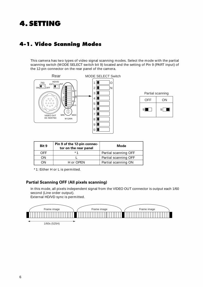
This camera has two types of video signal scanning modes. Select the mode with the partialscanning switch (MODE SELECT switch bit 9) located and the setting of Pin 9 (PART input) ofthe 12-pin connector on the rear panel of the camera.
Partial Scanning OFF (All pixels scanning)
In this mode, all pixels independent signal from the VIDEO OUT connector is output each 1/60second (Line order output).External HD/VD sync is permitted.
ON OFF
EXT INTHD/VD75Ω
SHT
TRG
M.G
MIN MAX
M GAIN
VIDEO OUTDC IN/SYNC
P.S
1 O
N2
3
4
9
OFF ON5
6
7
8
9
0
9
Rear MODE SELECT Switch
Partial scanning
Frame image
1/60s (525H)
Frame image Frame image
Bit 9
OFFONON
Pin 9 of the 12-pin connec-
tor on the rear panel
*1L
H or OPEN
Mode
Partial scanning OFFPartial scanning OFFPartial scanning ON
*1: Either H or L is permitted.
7
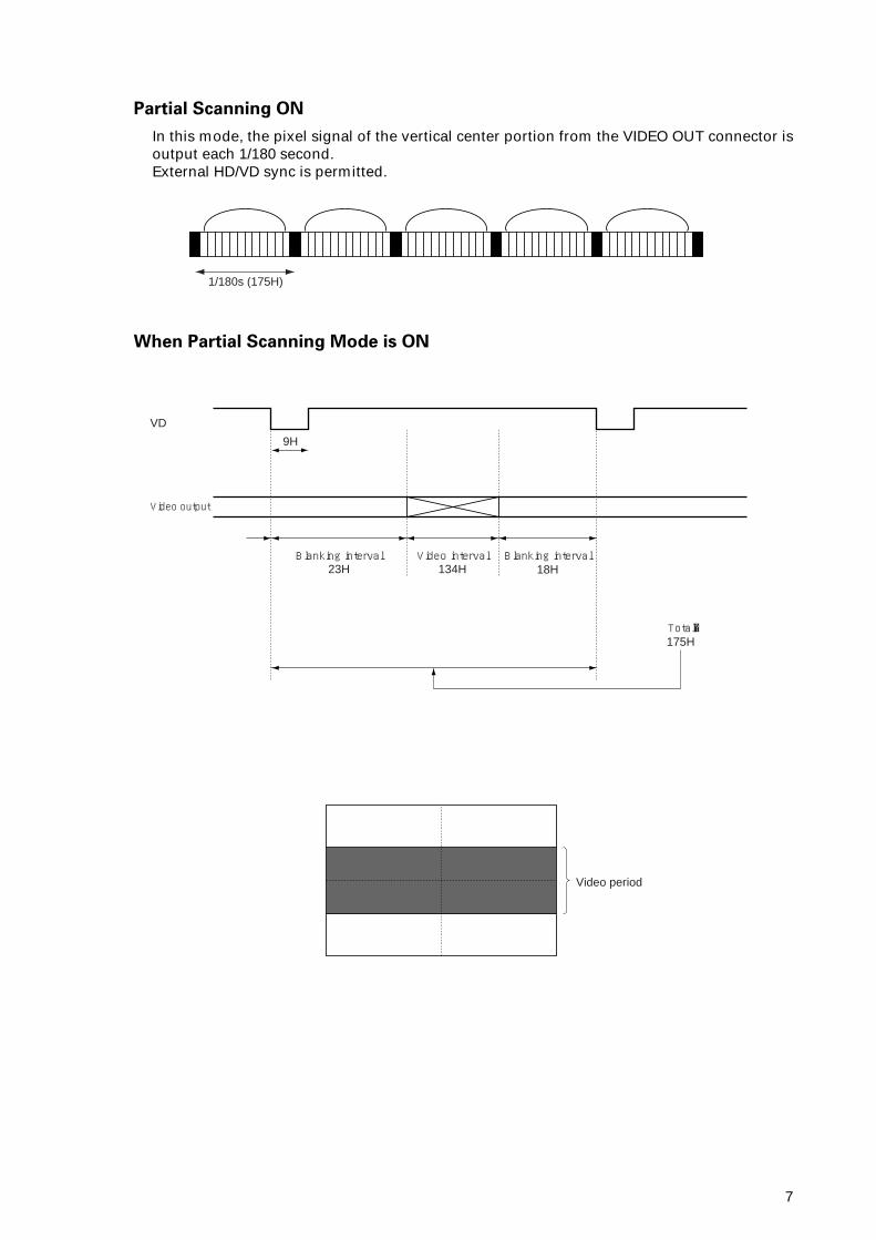
9H
Blanking interval
Video output
VD
23HBlanking interval
Total175H
18HVideo interval
134H
Video period
When Partial Scanning Mode is ON
Partial Scanning ON
In this mode, the pixel signal of the vertical center portion from the VIDEO OUT connector isoutput each 1/180 second.External HD/VD sync is permitted.
1/180s (175H)
8
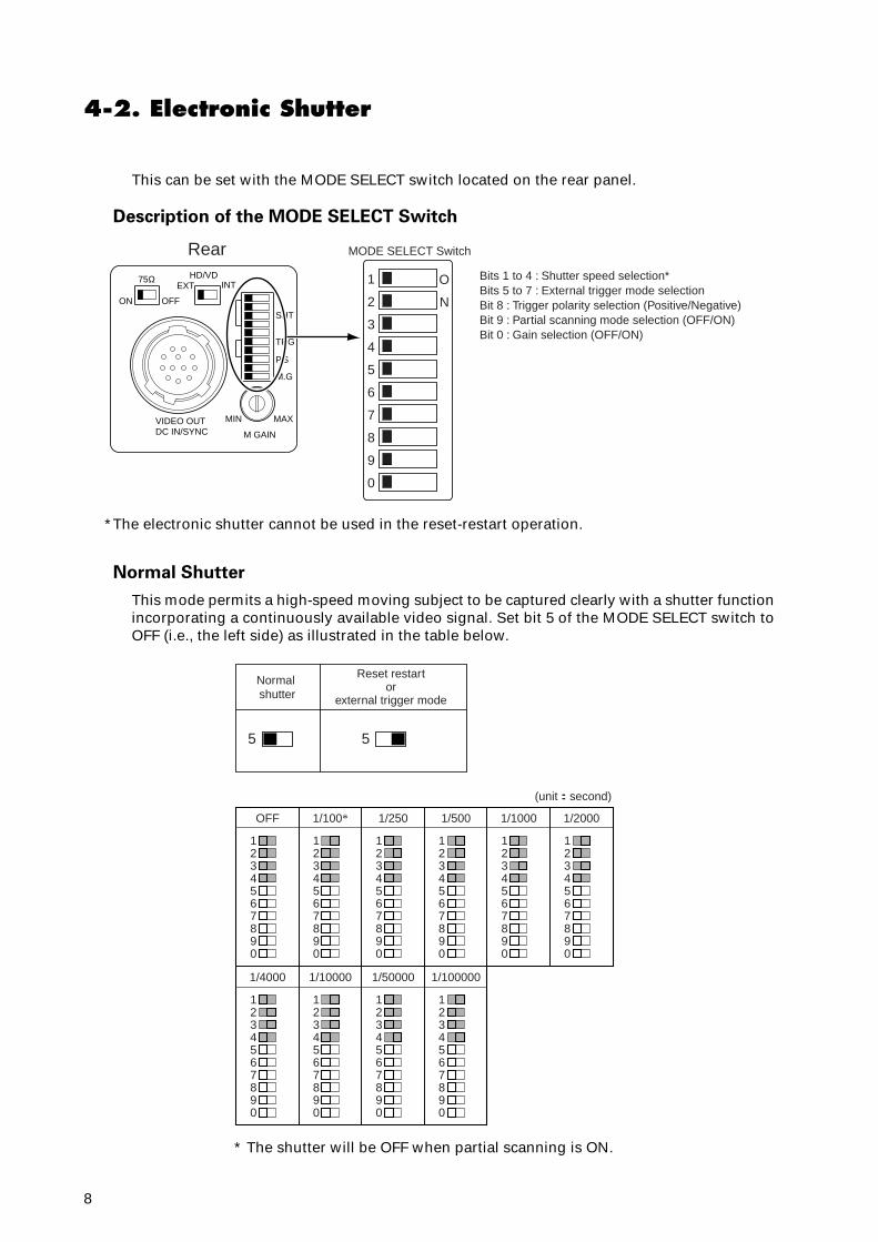
4-2. Electronic Shutter
This can be set with the MODE SELECT switch located on the rear panel.
Description of the MODE SELECT Switch
*The electronic shutter cannot be used in the reset-restart operation.
ON OFF
EXT INTHD/VD75Ω
SHT
TRG
M.G
MIN MAX
M GAIN
VIDEO OUTDC IN/SYNC
P.S
1 O
N2
3
4
5
6
7
8
9
0
Rear MODE SELECT Switch
Bits 1 to 4 : Shutter speed selection*Bits 5 to 7 : External trigger mode selectionBit 8 : Trigger polarity selection (Positive/Negative)Bit 9 : Partial scanning mode selection (OFF/ON)Bit 0 : Gain selection (OFF/ON)
Normal Shutter
This mode permits a high-speed moving subject to be captured clearly with a shutter functionincorporating a continuously available video signal. Set bit 5 of the MODE SELECT switch toOFF (i.e., the left side) as illustrated in the table below.
5
Normal shutter
Reset restartor
external trigger mode
5
1
OFF
234567890
1
1/100*
234567890
1
1/250
234567890
1
1/500
234567890
1
1/4000
234567890
1
1/10000
234567890
1
1/50000
234567890
1
1/100000
234567890
1
1/1000
234567890
1
1/2000
(unit:second)
234567890
* The shutter will be OFF when partial scanning is ON.
9
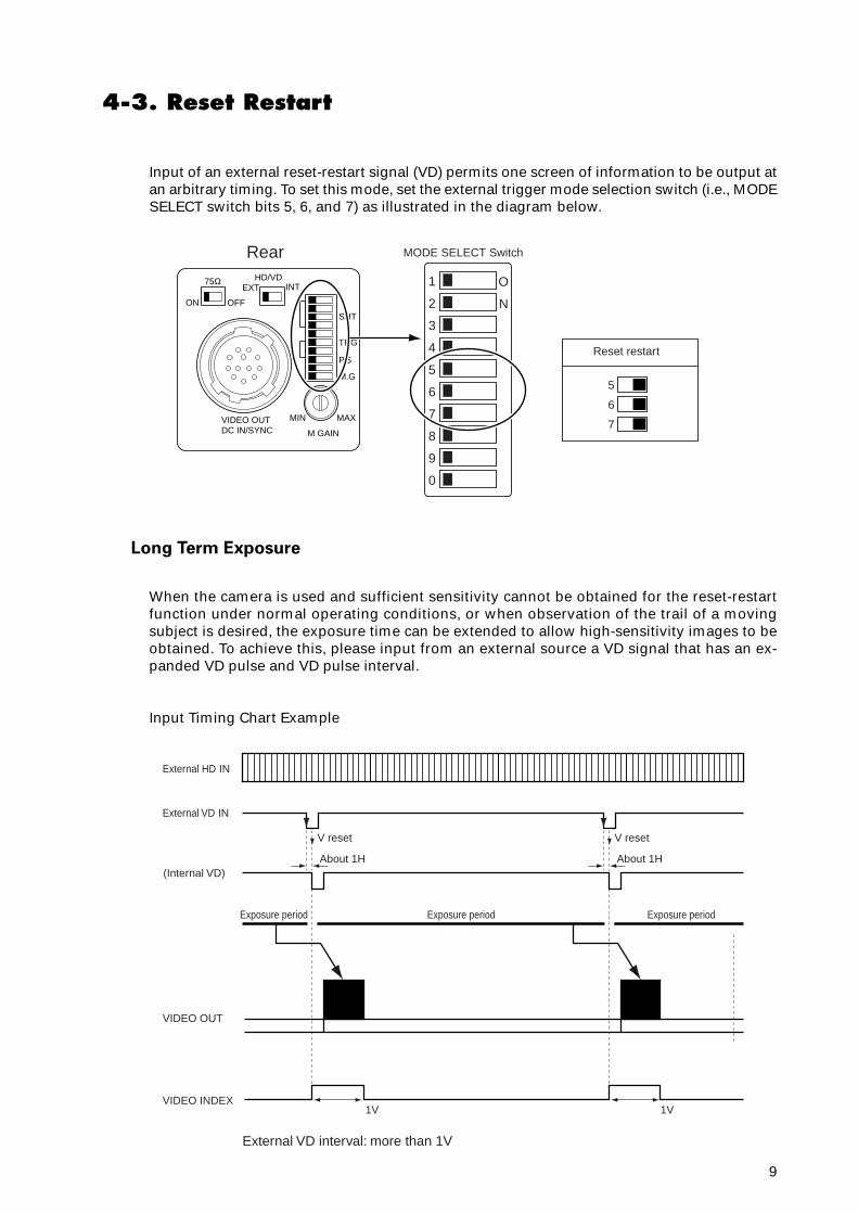
4-3. Reset Restart
Input of an external reset-restart signal (VD) permits one screen of information to be output atan arbitrary timing. To set this mode, set the external trigger mode selection switch (i.e., MODESELECT switch bits 5, 6, and 7) as illustrated in the diagram below.
Long Term Exposure
When the camera is used and sufficient sensitivity cannot be obtained for the reset-restartfunction under normal operating conditions, or when observation of the trail of a movingsubject is desired, the exposure time can be extended to allow high-sensitivity images to beobtained. To achieve this, please input from an external source a VD signal that has an ex-panded VD pulse and VD pulse interval.
Input Timing Chart Example
ON OFF
EXT INTHD/VD75Ω
SHT
TRG
M.G
MIN MAX
M GAIN
VIDEO OUTDC IN/SYNC
P.S
1 O
N2
3
4
55
6
7
8
9
0
6
7
Reset restart
Rear MODE SELECT Switch
External HD IN
External VD IN
(Internal VD)
VIDEO INDEX
VIDEO OUT
About 1H
V reset
Exposure period
External VD interval: more than 1V
Exposure period Exposure period
1V 1V
About 1H
V reset
10
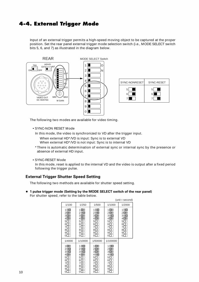
4-4. External Trigger Mode
Input of an external trigger permits a high-speed moving object to be captured at the properposition. Set the rear panel external trigger mode selection switch (i.e., MODE SELECT switchbits 5, 6, and 7) as illustrated in the diagram below.
The following two modes are available for video timing.
• SYNC-NON RESET ModeIn this mode, the video is synchronized to VD after the trigger input.
When external HD*/VD is input: Sync is to external VDWhen external HD*/VD is not input: Sync is to internal VD
*There is automatic determination of external sync or internal sync by the presence orabsence of external HD input.
• SYNC-RESET ModeIn this mode, reset is applied to the internal VD and the video is output after a fixed periodfollowing the trigger pulse.
External Trigger Shutter Speed Setting
The following two methods are available for shutter speed setting.
• 1 pulse trigger mode (Setting by the MODE SELECT switch of the rear panel)
For shutter speed, refer to the table below.
ON OFF
EXT INTHD/VD75Ω
SHT
TRG
M.G
MIN MAX
M GAIN
VIDEO OUTDC IN/SYNC
P.S
1 O
N2
3
4
55
6
7
8
9
0
6
7
5
6
7
SYNC-NONRESET SYNC-RESET
REAR MODE SELECT Switch
1
1/100
234567890
1
1/250
234567890
1
1/500
234567890
1
1/4000
234567890
1
1/10000
234567890
1
1/50000
234567890
1
1/100000
234567890
1
1/1000
234567890
1
1/2000
(unit:second)
234567890
11
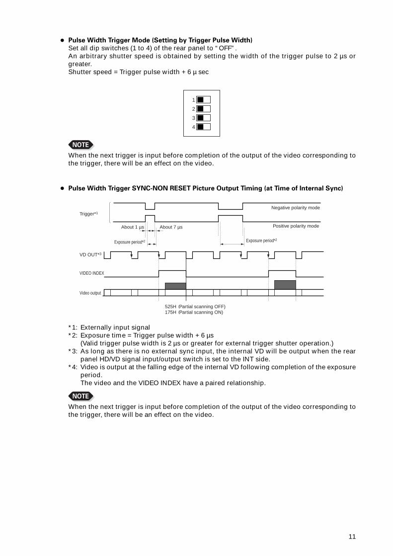
• Pulse Width Trigger Mode (Setting by Trigger Pulse Width)
Set all dip switches (1 to 4) of the rear panel to “OFF”.An arbitrary shutter speed is obtained by setting the width of the trigger pulse to 2 µs orgreater.Shutter speed = Trigger pulse width + 6 µ sec
NOTE
When the next trigger is input before completion of the output of the video corresponding tothe trigger, there will be an effect on the video.
1
2
3
4
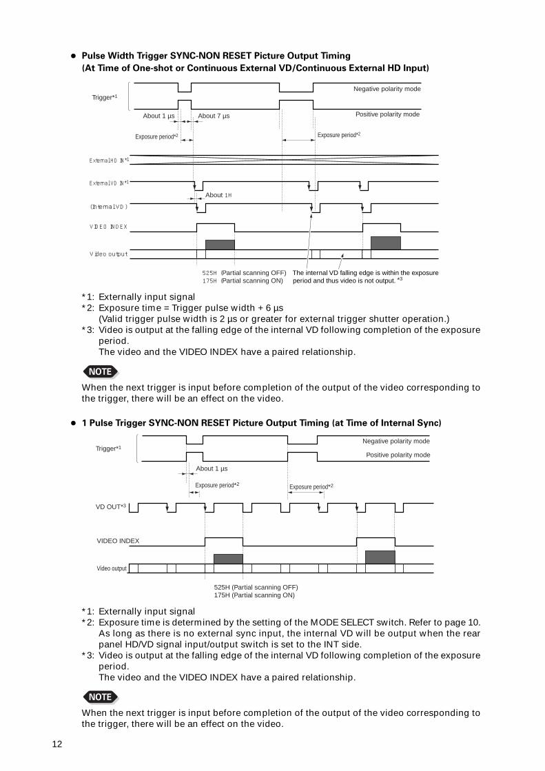
• Pulse Width Trigger SYNC-NON RESET Picture Output Timing (at Time of Internal Sync)
*1: Externally input signal*2: Exposure time = Trigger pulse width + 6 µs
(Valid trigger pulse width is 2 µs or greater for external trigger shutter operation.)*3: As long as there is no external sync input, the internal VD will be output when the rear
panel HD/VD signal input/output switch is set to the INT side.*4: Video is output at the falling edge of the internal VD following completion of the exposure
period.The video and the VIDEO INDEX have a paired relationship.
NOTE
When the next trigger is input before completion of the output of the video corresponding tothe trigger, there will be an effect on the video.
About 1 µs
Exposure period*2
Video output
525H (Partial scanning OFF)175H (Partial scanning ON)
VIDEO INDEX
VD OUT*3
Trigger*1
Exposure period*2
Negative polarity mode
Positive polarity modeAbout 7 µs
12
• Pulse Width Trigger SYNC-NON RESET Picture Output Timing
(At Time of One-shot or Continuous External VD/Continuous External HD Input)
*1: Externally input signal*2: Exposure time = Trigger pulse width + 6 µs
(Valid trigger pulse width is 2 µs or greater for external trigger shutter operation.)*3: Video is output at the falling edge of the internal VD following completion of the exposure
period.The video and the VIDEO INDEX have a paired relationship.
NOTE
When the next trigger is input before completion of the output of the video corresponding tothe trigger, there will be an effect on the video.
About 1 µs
Exposure period*2
Video output
525H (Partial scanning OFF)175H (Partial scanning ON)
The internal VD falling edge is within the exposure period and thus video is not output. *3
VIDEO INDEX
External VD IN*1
External HD IN*1
(Internal VD)
About 7 µs
About 1H
Negative polarity mode
Positive polarity mode
Exposure period*2
Trigger*1
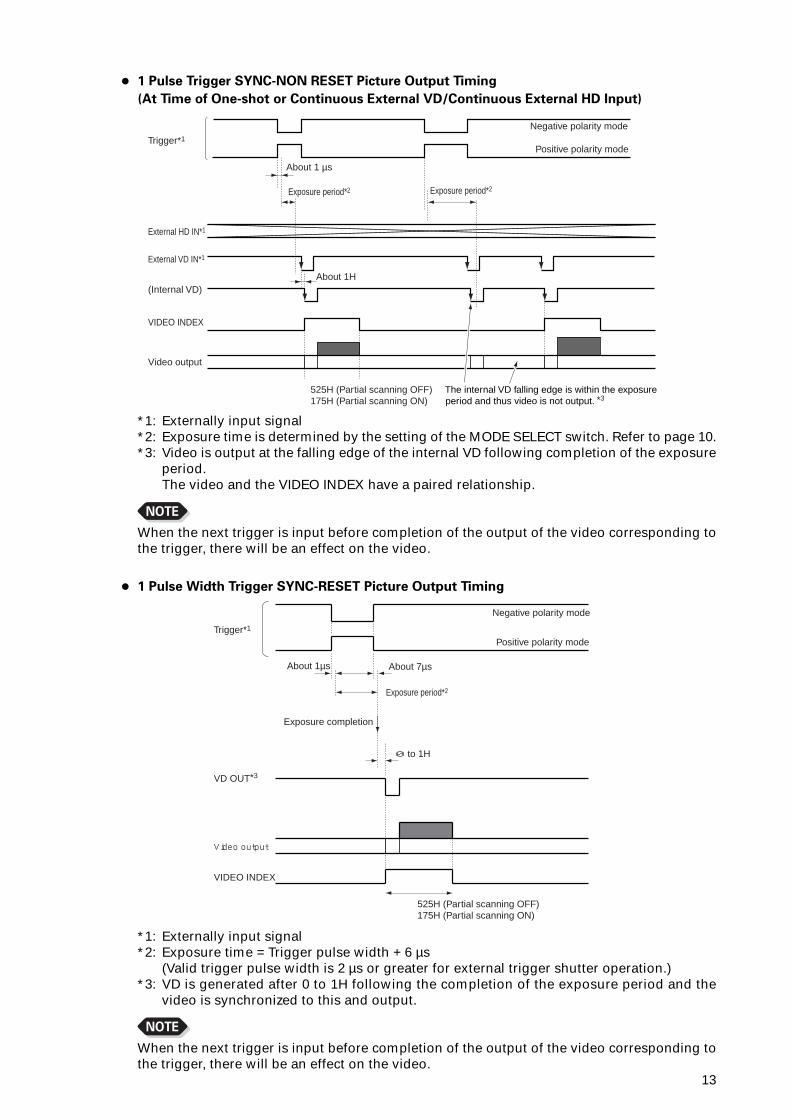
• 1 Pulse Trigger SYNC-NON RESET Picture Output Timing (at Time of Internal Sync)
About 1 µs
Exposure period*2
Video output
525H (Partial scanning OFF)175H (Partial scanning ON)
VIDEO INDEX
VD OUT*3
Trigger*1Negative polarity mode
Positive polarity mode
Exposure period*2
*1: Externally input signal*2: Exposure time is determined by the setting of the MODE SELECT switch. Refer to page 10.
As long as there is no external sync input, the internal VD will be output when the rearpanel HD/VD signal input/output switch is set to the INT side.
*3: Video is output at the falling edge of the internal VD following completion of the exposureperiod.The video and the VIDEO INDEX have a paired relationship.
NOTE
When the next trigger is input before completion of the output of the video corresponding tothe trigger, there will be an effect on the video.
13
• 1 Pulse Trigger SYNC-NON RESET Picture Output Timing
(At Time of One-shot or Continuous External VD/Continuous External HD Input)
*1: Externally input signal*2: Exposure time is determined by the setting of the MODE SELECT switch. Refer to page 10.*3: Video is output at the falling edge of the internal VD following completion of the exposure
period.The video and the VIDEO INDEX have a paired relationship.
NOTE
When the next trigger is input before completion of the output of the video corresponding tothe trigger, there will be an effect on the video.
About 1 µs
Video output
525H (Partial scanning OFF)175H (Partial scanning ON)
The internal VD falling edge is within the exposure period and thus video is not output. *3
VIDEO INDEX
External VD IN*1
External HD IN*1
(Internal VD)
Trigger*1
About 1H
Negative polarity mode
Positive polarity mode
Exposure period*2Exposure period*2
About 1µs About 7µs
Exposure completion
0 to 1H
Video output
VIDEO INDEX
VD OUT*3
Trigger*1
525H (Partial scanning OFF)175H (Partial scanning ON)
Negative polarity mode
Positive polarity mode
Exposure period*2
• 1 Pulse Width Trigger SYNC-RESET Picture Output Timing
*1: Externally input signal*2: Exposure time = Trigger pulse width + 6 µs
(Valid trigger pulse width is 2 µs or greater for external trigger shutter operation.)*3: VD is generated after 0 to 1H following the completion of the exposure period and the
video is synchronized to this and output.
NOTE
When the next trigger is input before completion of the output of the video corresponding tothe trigger, there will be an effect on the video.
14
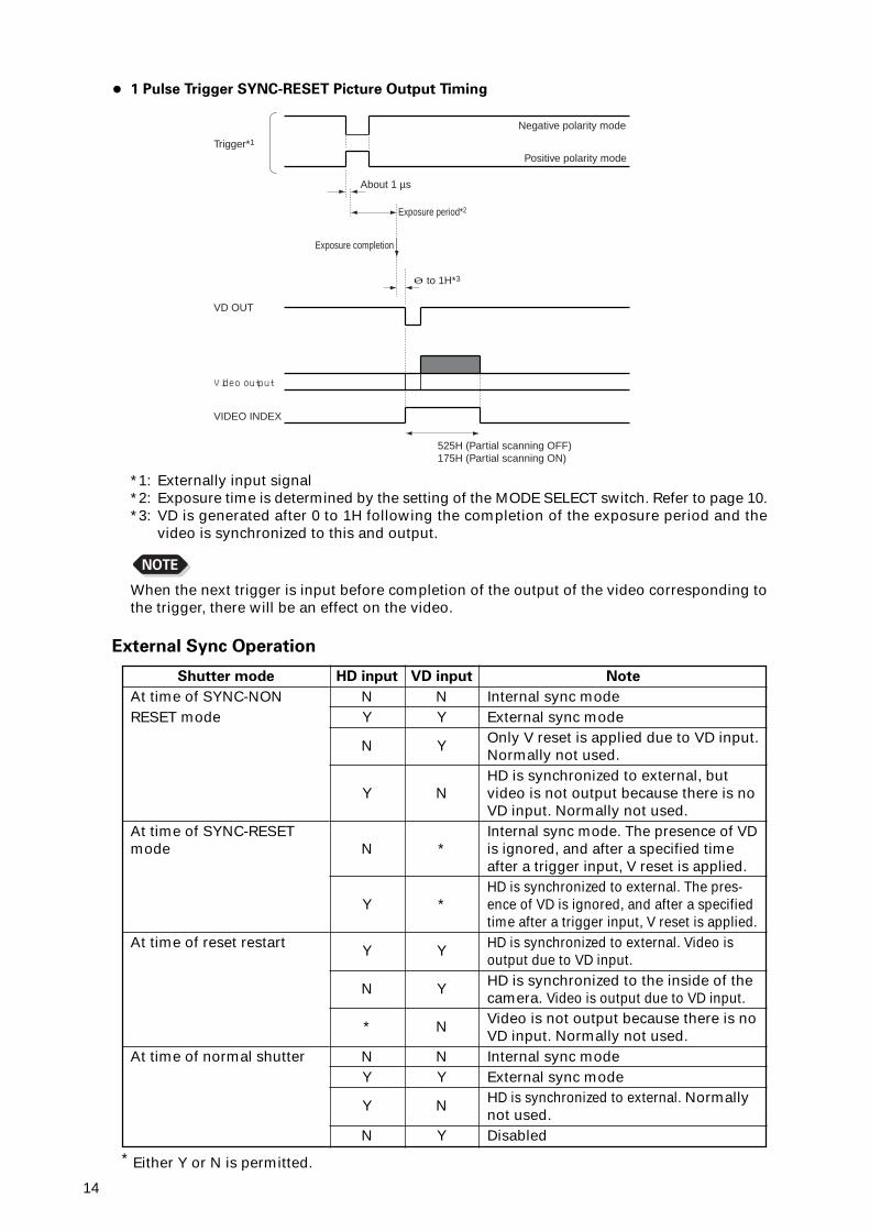
• 1 Pulse Trigger SYNC-RESET Picture Output Timing
*1: Externally input signal*2: Exposure time is determined by the setting of the MODE SELECT switch. Refer to page 10.*3: VD is generated after 0 to 1H following the completion of the exposure period and the
video is synchronized to this and output.
NOTE
When the next trigger is input before completion of the output of the video corresponding tothe trigger, there will be an effect on the video.
About 1 µs
Exposure completion
0 to 1H*3
Exposure period*2
Video output
VIDEO INDEX
VD OUT
Trigger*1
525H (Partial scanning OFF)175H (Partial scanning ON)
Negative polarity mode
Positive polarity mode
External Sync Operation
Shutter mode
At time of SYNC-NONRESET mode
At time of SYNC-RESETmode
At time of reset restart
At time of normal shutter
HD input
NY
N
Y
N
Y
Y
N
∗
NY
Y
N
VD input
NY
Y
N
∗
∗
Y
Y
N
NY
N
Y
Note
Internal sync modeExternal sync modeOnly V reset is applied due to VD input.Normally not used.HD is synchronized to external, butvideo is not output because there is noVD input. Normally not used.Internal sync mode. The presence of VDis ignored, and after a specified timeafter a trigger input, V reset is applied.HD is synchronized to external. The pres-ence of VD is ignored, and after a specifiedtime after a trigger input, V reset is applied.HD is synchronized to external. Video isoutput due to VD input.HD is synchronized to the inside of thecamera. Video is output due to VD input.Video is not output because there is noVD input. Normally not used.Internal sync modeExternal sync modeHD is synchronized to external. Normallynot used.Disabled
∗ Either Y or N is permitted.
15
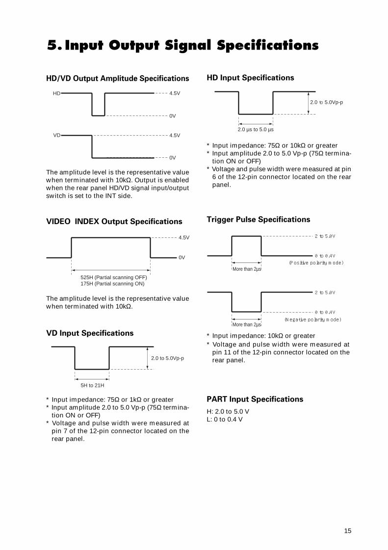
5. Input Output Signal Specifications
HD/VD Output Amplitude Specifications
The amplitude level is the representative valuewhen terminated with 10kΩ. Output is enabledwhen the rear panel HD/VD signal input/outputswitch is set to the INT side.
4.5VHD
VD
0V
4.5V
0V
VIDEO INDEX Output Specifications
The amplitude level is the representative valuewhen terminated with 10kΩ.
4.5V
0V
525H (Partial scanning OFF)175H (Partial scanning ON)
VD Input Specifications
* Input impedance: 75Ω or 1kΩ or greater* Input amplitude 2.0 to 5.0 Vp-p (75Ω termina-
tion ON or OFF)* Voltage and pulse width were measured at
pin 7 of the 12-pin connector located on therear panel.
5H to 21H
2.0 to 5.0Vp-p
HD Input Specifications
* Input impedance: 75Ω or 10kΩ or greater* Input amplitude 2.0 to 5.0 Vp-p (75Ω termina-
tion ON or OFF)* Voltage and pulse width were measured at pin
6 of the 12-pin connector located on the rearpanel.
2.0 µs to 5.0 µs
2.0 to 5.0Vp-p
Trigger Pulse Specifications
* Input impedance: 10kΩ or greater* Voltage and pulse width were measured at
pin 11 of the 12-pin connector located on therear panel.
More than 2µs
More than 2µs
2 to 5.0V
0 to 0.4V(Positive polarity mode)
(Negative polarity mode)
2 to 5.0V
0 to 0.4V
PART Input Specifications
H: 2.0 to 5.0 VL: 0 to 0.4 V
16
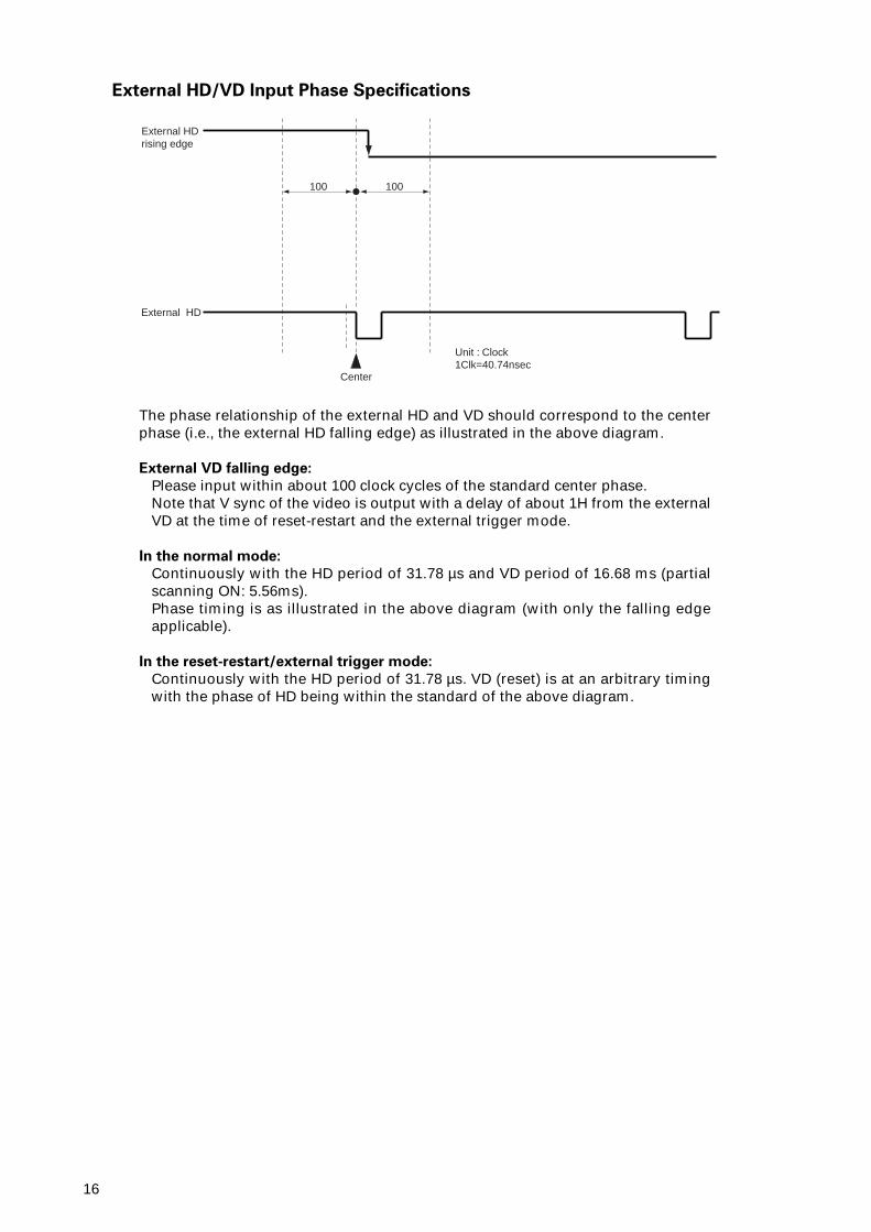
External HD/VD Input Phase Specifications
The phase relationship of the external HD and VD should correspond to the centerphase (i.e., the external HD falling edge) as illustrated in the above diagram.
External VD falling edge:
Please input within about 100 clock cycles of the standard center phase.Note that V sync of the video is output with a delay of about 1H from the externalVD at the time of reset-restart and the external trigger mode.
In the normal mode:
Continuously with the HD period of 31.78 µs and VD period of 16.68 ms (partialscanning ON: 5.56ms).Phase timing is as illustrated in the above diagram (with only the falling edgeapplicable).
In the reset-restart/external trigger mode:
Continuously with the HD period of 31.78 µs. VD (reset) is at an arbitrary timingwith the phase of HD being within the standard of the above diagram.
External HD rising edge
100
Center
100
Unit : Clock1Clk=40.74nsec
External HD
17
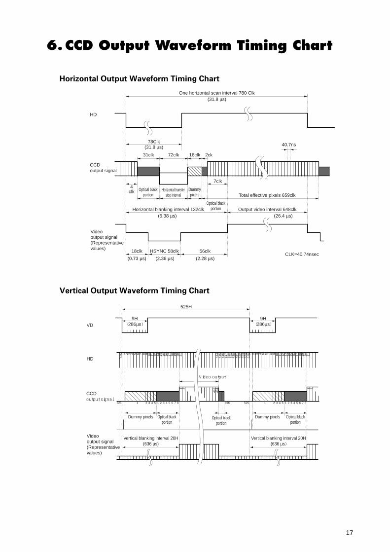
78Clk
31clk
18clk HSYNC 58clkCLK=40.74nsec
56clk
72clk 16clk 2ck
7clk
40.7ns
Optical black portion
HD
CCDoutput signal
Video output signal (Representative values)
Total effective pixels 659clk
Horizontal blanking interval 132clkOptical black
portion
Horizontal transfer stop interval
Dummy pixels
4clk
(31.8 µs)
(5.38 µs)
(0.73 µs) (2.36 µs) (2.28 µs)
Output video interval 648clk(26.4 µs)
One horizontal scan interval 780 Clk(31.8 µs)
9H
525
525
524
523
522
521
520
519
518
517
516
515
5141 2 3 4 5 6 7 8 9 10 11 12 13 14 15 16
1 2
493
494
17 18 19 20 21 1 2 3 4 5 6 7 8 9 10 11 12 13 14 15 16 17 18 19 20 21525H
(286µs)
Dummy pixels
Vertical blanking interval 20H(636 µs)
Vertical blanking interval 20H(636 µs)
Optical black portion
Dummy pixels Optical black portion
Optical black portion
Video output
9H(286µs)
525 1 2 3 4 5 1 2 3 4 5 6 7 8
1 2
1 2 3 4 5 1 2 3 4 5 6 7 8496 525
HD
VD
CCDoutput signal
Video output signal (Representative values)
6.CCD Output Waveform Timing Chart
Horizontal Output Waveform Timing Chart
Vertical Output Waveform Timing Chart
18
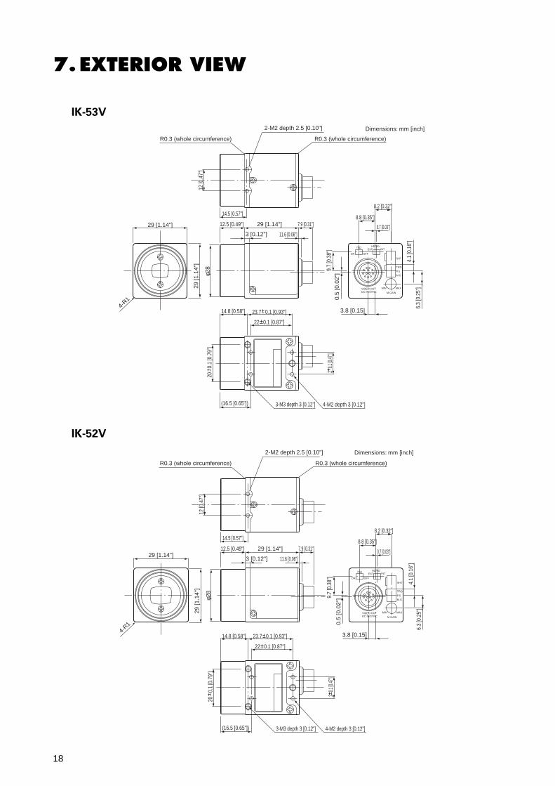
7.EXTERIOR VIEW
IK-53V
8.2 [0.32"]
9.7
[0.3
8"]
φ28
29 [1
.14"
]
4-R1
20
0.1
[0.7
9"]
2 0.
1 [0.4
7"]
4.1
[0.1
6"]
6.3
[0.2
5"]
0.5
[0.0
2"]
0.7 [0.03"]
8.8 [0.35"]
2-M2 depth 2.5 [0.10"]
R0.3 (whole circumference)
Dimensions: mm [inch]
R0.3 (whole circumference)
ON OFF
EXT INTHD/VD75Ω
SHT
TRG
M.G
MIN MAX
M GAIN
VIDEO OUTDC IN/SYNC
P.S
3.8 [0.15]
14.5 [0.57"]
12.5 [0.49"]29 [1.14"] 29 [1.14"] 7.9 [0.31"]
3 [0.12"]
14.8 [0.58"] 23.7 0.1 [0.93"]
22 0.1 [0.87"]
(16.5 [0.65"]) 3-M3 depth 3 [0.12"] 4-M2 depth 3 [0.12"]
11.6 [0.06"]
12 [0
.47"
]
8.2 [0.32"]
9.7
[0.3
8"]
φ28
20
0.1
[0.7
9"]
2 0.
1 [0.4
7"]
4.1
[0.1
6"]
6.3
[0.2
5"]
0.5
[0.0
2"]
0.7 [0.03"]
8.8 [0.35"]
2-M2 depth 2.5 [0.10"]
R0.3 (whole circumference)R0.3 (whole circumference)
ON OFF
EXT INTHD/VD75Ω
SHT
TRG
M.G
MIN MAX
M GAIN
VIDEO OUTDC IN/SYNC
P.S
3.8 [0.15]
14.5 [0.57"]
12.5 [0.49"] 29 [1.14"] 7.9 [0.31"]
3 [0.12"]
14.8 [0.58"] 23.7 0.1 [0.93"]
22 0.1 [0.87"]
(16.5 [0.65"]) 3-M3 depth 3 [0.12"] 4-M2 depth 3 [0.12"]
11.6 [0.06"]
29 [1
.14"
]
4-R1
29 [1.14"]
Dimensions: mm [inch]
12 [0
.47"
]
IK-52V
19
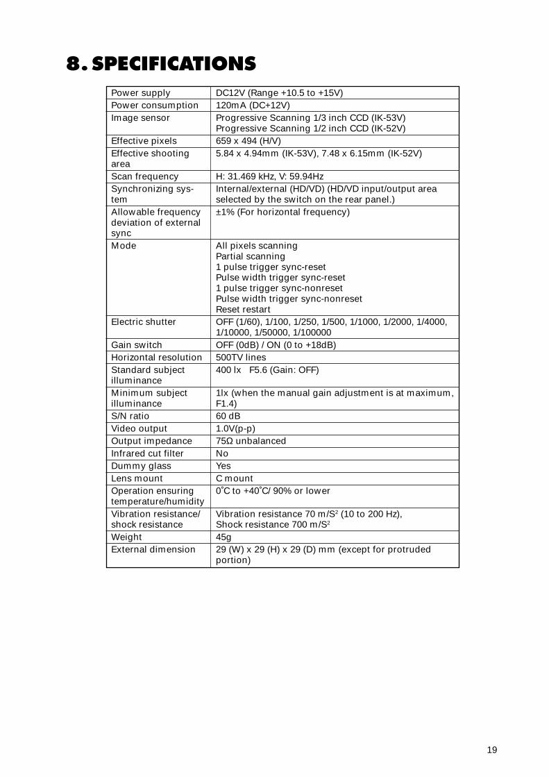
8.SPECIFICATIONSPower supplyPower consumptionImage sensor
Effective pixelsEffective shootingareaScan frequencySynchronizing sys-temAllowable frequencydeviation of externalsyncMode
Electric shutter
Gain switchHorizontal resolutionStandard subjectilluminanceMinimum subjectilluminanceS/N ratioVideo outputOutput impedanceInfrared cut filterDummy glassLens mountOperation ensuringtemperature/humidityVibration resistance/shock resistanceWeightExternal dimension
DC12V (Range +10.5 to +15V)120mA (DC+12V)Progressive Scanning 1/3 inch CCD (IK-53V)Progressive Scanning 1/2 inch CCD (IK-52V)659 x 494 (H/V)5.84 x 4.94mm (IK-53V), 7.48 x 6.15mm (IK-52V)
H: 31.469 kHz, V: 59.94HzInternal/external (HD/VD) (HD/VD input/output areaselected by the switch on the rear panel.)±1% (For horizontal frequency)
All pixels scanningPartial scanning1 pulse trigger sync-resetPulse width trigger sync-reset1 pulse trigger sync-nonresetPulse width trigger sync-nonresetReset restartOFF (1/60), 1/100, 1/250, 1/500, 1/1000, 1/2000, 1/4000,1/10000, 1/50000, 1/100000OFF (0dB) / ON (0 to +18dB)500TV lines400 lx F5.6 (Gain: OFF)
1lx (when the manual gain adjustment is at maximum,F1.4)60 dB1.0V(p-p)75Ω unbalancedNoYesC mount0˚C to +40˚C/ 90% or lower
Vibration resistance 70 m/S2 (10 to 200 Hz),Shock resistance 700 m/S2
45g29 (W) x 29 (H) x 29 (D) mm (except for protrudedportion)
20
400
0.1
0.2
0.3
0.4
0.5
0.6
0.7
0.8
0.9
1.0
0500 600 700 800 900 1000
Wave length (nm)
Rel
ativ
e S
ensi
tivity
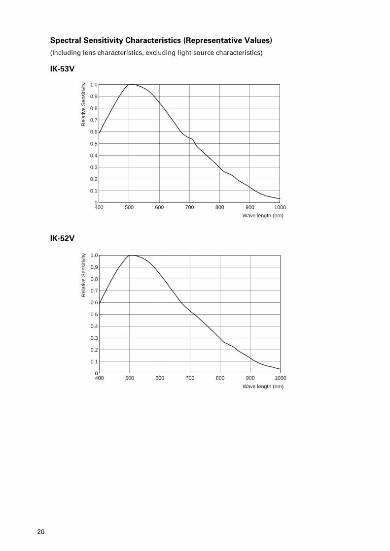
Spectral Sensitivity Characteristics (Representative Values)
(Including lens characteristics, excluding light source characteristics)
IK-53V
IK-52V
400
0.1
0.2
0.3
0.4
0.5
0.6
0.7
0.8
0.9
1.0
0500 600 700 800 900 1000
Wave length (nm)
Rel
ativ
e S
ensi
tivity