catia-cadam interfacecatiadesign.org/_doc/v5r14/catpdfcciug_c2/cciug.pdf · the catia-cadam...
TRANSCRIPT
CATIA-CADAM Interface
Preface
What's New?
Getting Started
Methodology CCD to V5 Mapping
Structural Elements Geometric Elements Non-Text Elements Text-Based Elements Dimensions and Dimension Properties
V5 to CCD Mapping Structural Elements Geometric Elements Non-Text Elements Text-Based Elements Dimensions and Dimension Properties
User Tasks
Setting Options Opening a CCD Model in V5 Saving V5 to CCD Setting System Variable to Allow V5 to CCD Translation Preparing a CCD Model
Glossary
Index
Preface The CATIA-CADAM Interface User's Guide describes how to translate drafting documents from CADAM Drafting to CATIA Version 5 and from CATIA Version 5 to CADAM Drafting. It explains how the product should be used and provides specific instructions for:
● Setting Options for the CATIA-CADAM Interface product
● Opening a CADAM Drafting model
● Saving a V5 Drafting document as a CADAM Drafting model
It contains a detailed mapping table that shows how CADAM Drafting elements are interpreted in CATIA and how CATIA Drafting elements are interpreted in CADAM. In addition, guidelines are offered for preparing a CADAM Drafting model for translation.

What's New?
Enhanced Functionality
None

Getting Started
MethodologyCCD to V5 MappingV5 to CCD Mapping
CATIA-CADAM Interface Methodology
The CATIA-CADAM Interface product allows you to integrate your CADAM Drafting environment with other V5 CATIA product offerings. Depending on your intended usage, there are two basic design methodologies that the CATIA-CADAM Interface product supports for integrating your V5 CATIA and CADAM drafting environments. They are as follows:
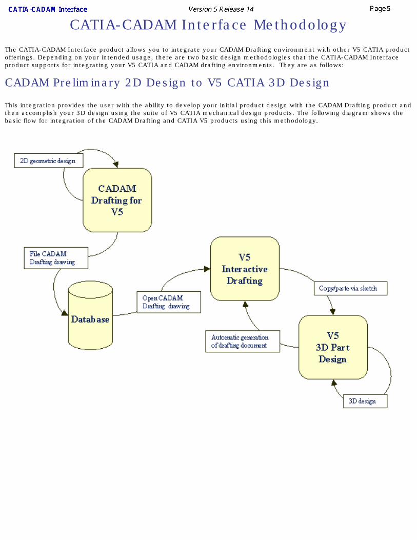
CADAM Preliminary 2D Design to V5 CATIA 3D Design
This integration provides the user with the ability to develop your initial product design with the CADAM Drafting product and then accomplish your 3D design using the suite of V5 CATIA mechanical design products. The following diagram shows the basic flow for integration of the CADAM Drafting and CATIA V5 products using this methodology.
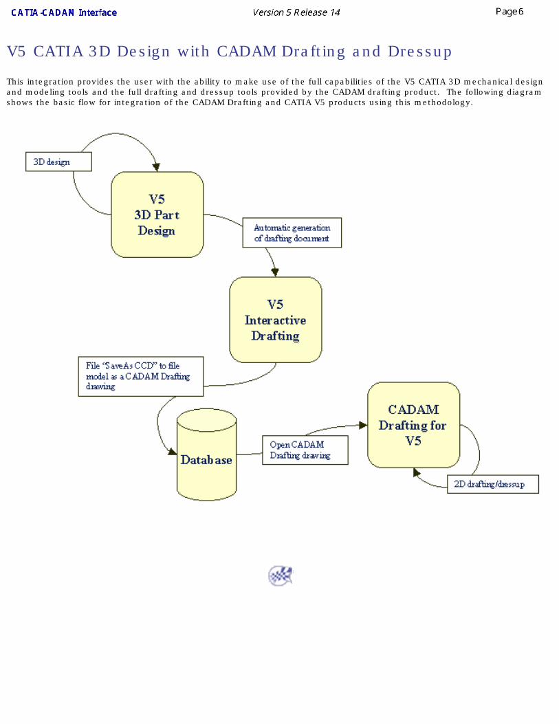
V5 CATIA 3D Design with CADAM Drafting and Dressup
This integration provides the user with the ability to make use of the full capabilities of the V5 CATIA 3D mechanical design and modeling tools and the full drafting and dressup tools provided by the CADAM drafting product. The following diagram shows the basic flow for integration of the CADAM Drafting and CATIA V5 products using this methodology.
CADAM Drafting to V5 Interactive Drafting -- Element Mapping
This section describes how CADAM Drafting elements are interpreted in CATIA.
The CATIA-CADAM Interface product provides the capability of opening a CADAM Drafting model directly in the V5 Interactive Drafting environment. As a CADAM Drafting model is opened, the elements in the model are converted from CADAM Drafting format to V5 Interactive Drafting format. The conversion handles all 2D geometric and annotation elements supported in a CADAM Drafting model.
Currently in V5, not all elements and element properties supported in CADAM Drafting are supported in the Interactive Drafting product. In most of these cases, the element or element property is transferred to the closest compatible element or property. In some cases, complex elements are exploded into primitive elements during the transfer. As additional elements and element properties are incorporated into the Interactive Drafting product in future releases, the CATIA-CADAM Interface product will be updated to provide a more accurate mapping.
The following tables provide detailed information for the specific mapping between CADAM Drafting and V5 Interactive Drafting. The tables are organized by element type:
Structural ElementsGeometric ElementsNon-Text Elements
Text-Based ElementsDimensions and Dimension Properties
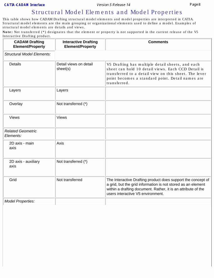
Structural Model Elements and Model PropertiesThis table shows how CADAM Drafting structural model elements and model properties are interpreted in CATIA. Structural model elements are the main grouping or organizational elements used to define a model. Examples of structural model elements are details and views.Note: Not transferred (*) designates that the element or property is not supported in the current release of the V5 Interactive Drafting product.
CADAM Drafting Element/Property
Interactive Drafting Element/Property
Comments
Structural Model Elements:
Details Detail views on detail sheet(s)
V5 Drafting has multiple detail sheets, and each sheet can hold 10 detail views. Each CCD Detail is transferred to a detail view on this sheet. The lever point becomes a standard point. Detail names are transferred.
Layers Layers
Overlay Not transferred (*)
Views Views
Related Geometric Elements:
2D axis - main axis
Axis
2D axis - auxiliary axis
Not transferred (*)
Grid Not transferred The Interactive Drafting product does support the concept of a grid, but the grid information is not stored as an element within a drafting document. Rather, it is an attribute of the users interactive V5 environment.
Model Properties:
Drafting standard (ANSI, ISO, JIS)
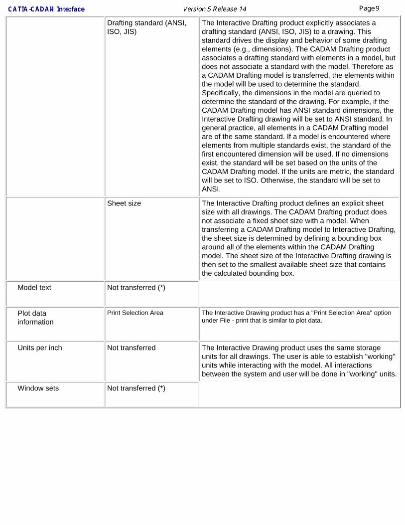
The Interactive Drafting product explicitly associates a drafting standard (ANSI, ISO, JIS) to a drawing. This standard drives the display and behavior of some drafting elements (e.g., dimensions). The CADAM Drafting product associates a drafting standard with elements in a model, but does not associate a standard with the model. Therefore as a CADAM Drafting model is transferred, the elements within the model will be used to determine the standard. Specifically, the dimensions in the model are queried to determine the standard of the drawing. For example, if the CADAM Drafting model has ANSI standard dimensions, the Interactive Drafting drawing will be set to ANSI standard. In general practice, all elements in a CADAM Drafting model are of the same standard. If a model is encountered where elements from multiple standards exist, the standard of the first encountered dimension will be used. If no dimensions exist, the standard will be set based on the units of the CADAM Drafting model. If the units are metric, the standard will be set to ISO. Otherwise, the standard will be set to ANSI.
Sheet size The Interactive Drafting product defines an explicit sheet size with all drawings. The CADAM Drafting product does not associate a fixed sheet size with a model. When transferring a CADAM Drafting model to Interactive Drafting, the sheet size is determined by defining a bounding box around all of the elements within the CADAM Drafting model. The sheet size of the Interactive Drafting drawing is then set to the smallest available sheet size that contains the calculated bounding box.
Model text Not transferred (*)
Plot data information
Print Selection Area The Interactive Drawing product has a "Print Selection Area" option under File - print that is similar to plot data.
Units per inch Not transferred The Interactive Drawing product uses the same storage units for all drawings. The user is able to establish "working" units while interacting with the model. All interactions between the system and user will be done in "working" units.
Window sets Not transferred (*)
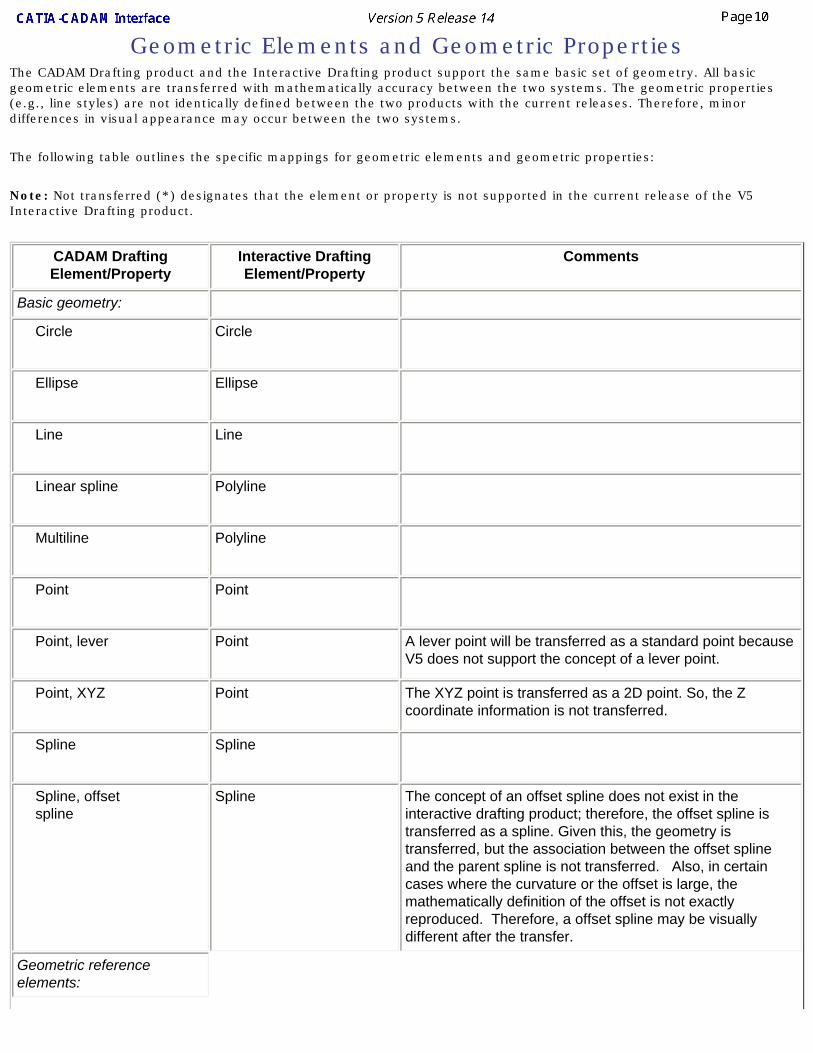
Geometric Elements and Geometric PropertiesThe CADAM Drafting product and the Interactive Drafting product support the same basic set of geometry. All basic geometric elements are transferred with mathematically accuracy between the two systems. The geometric properties (e.g., line styles) are not identically defined between the two products with the current releases. Therefore, minor differences in visual appearance may occur between the two systems.
The following table outlines the specific mappings for geometric elements and geometric properties:
Note: Not transferred (*) designates that the element or property is not supported in the current release of the V5 Interactive Drafting product.
CADAM Drafting Element/Property
Interactive Drafting Element/Property
Comments
Basic geometry:
Circle Circle
Ellipse Ellipse
Line Line
Linear spline Polyline
Multiline Polyline
Point Point
Point, lever Point A lever point will be transferred as a standard point because V5 does not support the concept of a lever point.
Point, XYZ Point The XYZ point is transferred as a 2D point. So, the Z coordinate information is not transferred.
Spline Spline
Spline, offset spline
Spline The concept of an offset spline does not exist in the interactive drafting product; therefore, the offset spline is transferred as a spline. Given this, the geometry is transferred, but the association between the offset spline and the parent spline is not transferred. Also, in certain cases where the curvature or the offset is large, the mathematically definition of the offset is not exactly reproduced. Therefore, a offset spline may be visually different after the transfer.
Geometric reference elements:
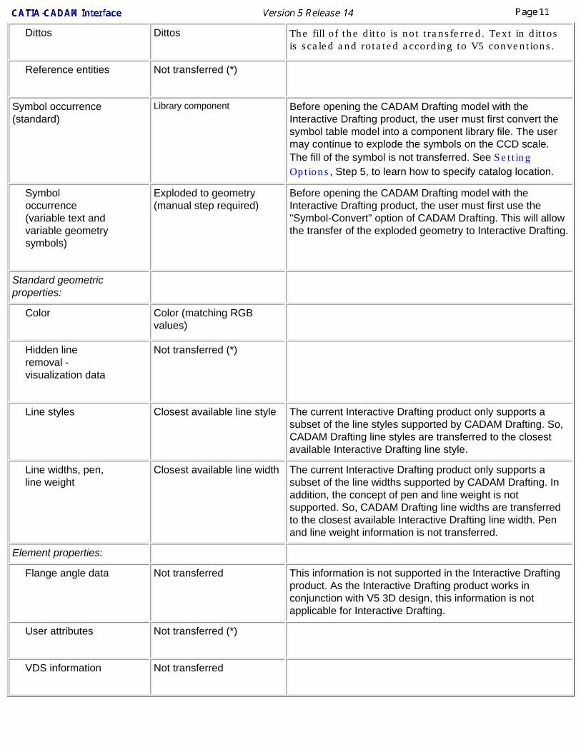
Dittos Dittos The fill of the ditto is not transferred. Text in dittos is scaled and rotated according to V5 conventions.
Reference entities Not transferred (*)
Symbol occurrence (standard)
Library component Before opening the CADAM Drafting model with the Interactive Drafting product, the user must first convert the symbol table model into a component library file. The user may continue to explode the symbols on the CCD scale. The fill of the symbol is not transferred. See Setting Options, Step 5, to learn how to specify catalog location.
Symbol occurrence (variable text and variable geometry symbols)
Exploded to geometry (manual step required)
Before opening the CADAM Drafting model with the Interactive Drafting product, the user must first use the "Symbol-Convert" option of CADAM Drafting. This will allow the transfer of the exploded geometry to Interactive Drafting.
Standard geometric properties:
Color Color (matching RGB values)
Hidden line removal - visualization data
Not transferred (*)
Line styles Closest available line style The current Interactive Drafting product only supports a subset of the line styles supported by CADAM Drafting. So, CADAM Drafting line styles are transferred to the closest available Interactive Drafting line style.
Line widths, pen, line weight
Closest available line width The current Interactive Drafting product only supports a subset of the line widths supported by CADAM Drafting. In addition, the concept of pen and line weight is not supported. So, CADAM Drafting line widths are transferred to the closest available Interactive Drafting line width. Pen and line weight information is not transferred.
Element properties:
Flange angle data Not transferred This information is not supported in the Interactive Drafting product. As the Interactive Drafting product works in conjunction with V5 3D design, this information is not applicable for Interactive Drafting.
User attributes Not transferred (*)
VDS information Not transferred


Non-Text Based AnnotationsNon-Text based annotations are defined as annotation related elements that do not have a text component. The following table outlines the specific mappings for non-text based annotations:
Note: Not transferred (*) designates that the element or property is not supported in the current release of the V5 Interactive Drafting product.
CADAM Drafting Element/Property
Interactive Drafting Element/Property
Comments
Geometric annotations:
Arrow without text Arrow The CADAM arrow supports a series of end conditions. Not all of these end conditions are supported by the current version of the Interactive Drafting product. Therefore, end conditions will be transferred to the best matching end condition.
Breakout Polyline
Dot Circle or areafill If the CADAM element is not filled, the element is transferred as a circle. If the CADAM element is filled, it is transferred as an areafill.
Raster Not transferred (*)
Rectangle Polyline or areafill If the CADAM element is not filled, the element is transferred as a polyline. If the CADAM element is filled, it is transferred as an areafill.
Section line Polyline
Triangle Polyline or areafill If the CADAM element is not filled, the element is transferred as a polyline. If the CADAM element is filled, it is transferred as an areafill.
Areafill and pattern data:
Areafill boundary Polyline
Areafill background color
Areafill color
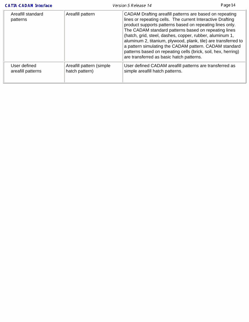
Areafill standard patterns
Areafill pattern CADAM Drafting areafill patterns are based on repeating lines or repeating cells. The current Interactive Drafting product supports patterns based on repeating lines only. The CADAM standard patterns based on repeating lines (hatch, grid, steel, dashes, copper, rubber, aluminum 1, aluminum 2, titanium, plywood, plank, tile) are transferred to a pattern simulating the CADAM pattern. CADAM standard patterns based on repeating cells (brick, soil, hex, herring) are transferred as basic hatch patterns.
User defined areafill patterns
Areafill pattern (simple hatch pattern)
User defined CADAM areafill patterns are transferred as simple areafill hatch patterns.
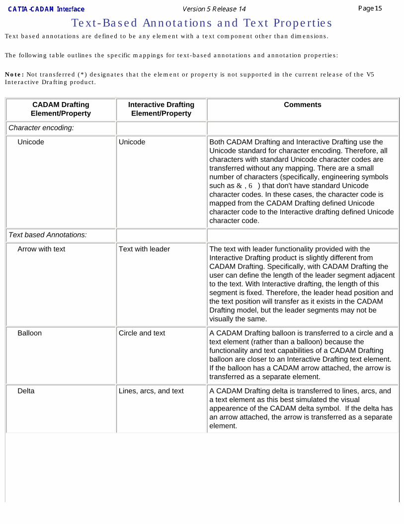
Text-Based Annotations and Text PropertiesText based annotations are defined to be any element with a text component other than dimensions.
The following table outlines the specific mappings for text-based annotations and annotation properties:
Note: Not transferred (*) designates that the element or property is not supported in the current release of the V5 Interactive Drafting product.
CADAM Drafting Element/Property
Interactive Drafting Element/Property
Comments
Character encoding:
Unicode Unicode Both CADAM Drafting and Interactive Drafting use the Unicode standard for character encoding. Therefore, all characters with standard Unicode character codes are transferred without any mapping. There are a small number of characters (specifically, engineering symbols such as & , 6 ) that don't have standard Unicode character codes. In these cases, the character code is mapped from the CADAM Drafting defined Unicode character code to the Interactive drafting defined Unicode character code.
Text based Annotations:
Arrow with text Text with leader The text with leader functionality provided with the Interactive Drafting product is slightly different from CADAM Drafting. Specifically, with CADAM Drafting the user can define the length of the leader segment adjacent to the text. With Interactive drafting, the length of this segment is fixed. Therefore, the leader head position and the text position will transfer as it exists in the CADAM Drafting model, but the leader segments may not be visually the same.
Balloon Circle and text A CADAM Drafting balloon is transferred to a circle and a text element (rather than a balloon) because the functionality and text capabilities of a CADAM Drafting balloon are closer to an Interactive Drafting text element. If the balloon has a CADAM arrow attached, the arrow is transferred as a separate element.
Delta Lines, arcs, and text A CADAM Drafting delta is transferred to lines, arcs, and a text element as this best simulated the visual appearence of the CADAM delta symbol. If the delta has an arrow attached, the arrow is transferred as a separate element.
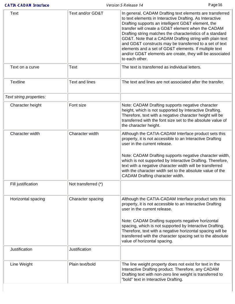
Text Text and/or GD&T In general, CADAM Drafting text elements are transferred to text elements in Interactive Drafting. As Interactive Drafting supports an intelligent GD&T element, the transfer will create a GD&T element when the CADAM Drafting string matches the characteristics of a standard GD&T. Note that a CADAM Drafting string with plain text and GD&T constructs may be transferred to a set of text elements and a set of GD&T elements. If multiple text and/or GD&T elements are create, they will be associated to each other.
Text on a curve Text The text is transferred as individual letters.
Textline Text and lines The text and lines are not associated after the transfer.
Text string properties:
Character height Font size Note: CADAM Drafting supports negative character height, which is not supported by Interactive Drafting. Therefore, text with a negative character height will be transferred with the font size set to the absolute value of the character height.
Character width Character width Although the CATIA-CADAM Interface product sets this property, it is not accessible to an Interactive Drafting user in the current release.
Note: CADAM Drafting supports negative character width, which is not supported by Interactive Drafting. Therefore, text with a negative character width will be transferred with the character width set to the absolute value of the CADAM Drafting character width.
Fill justification Not transferred (*)
Horizontal spacing Character spacing Although the CATIA-CADAM Interface product sets this property, it is not accessible to an Interactive Drafting user in the current release.
Note: CADAM Drafting supports negative horizontal spacing, which is not supported by Interactive Drafting. Therefore, text with a negative horizontal spacing will be transferred with the character spacing set to the absolute value of horizontal spacing.
Justification Justification
Line Weight Plain text/bold The line weight property does not exist for text in the Interactive Drafting product. Therefore, any CADAM Drafting text with non-zero line weight is transferred to "bold" text in Interactive Drafting.
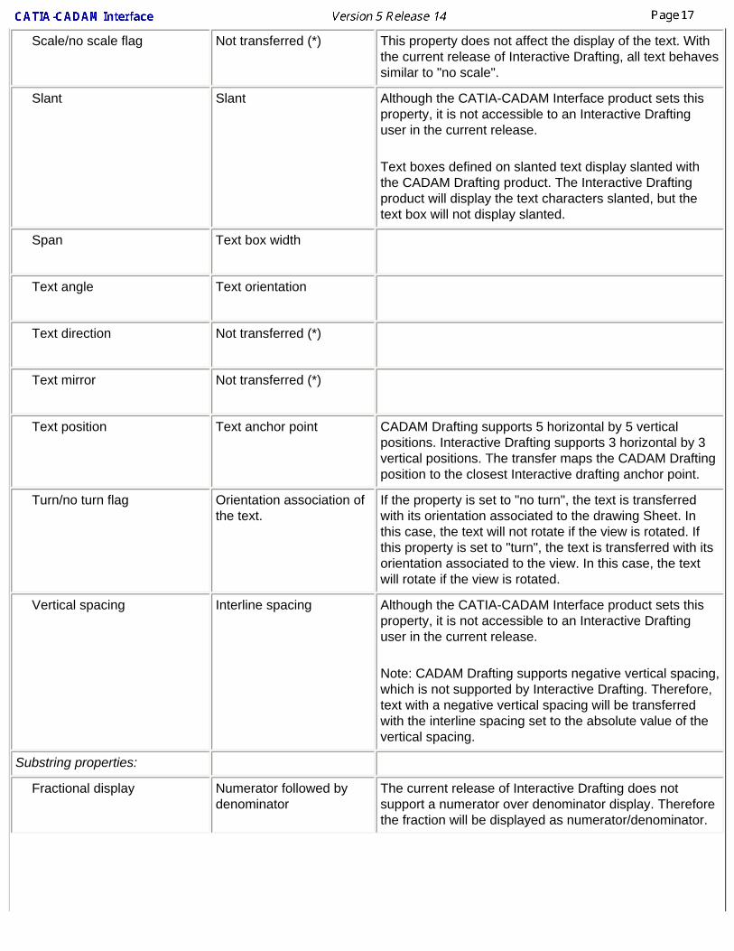
Scale/no scale flag Not transferred (*) This property does not affect the display of the text. With the current release of Interactive Drafting, all text behaves similar to "no scale".
Slant Slant Although the CATIA-CADAM Interface product sets this property, it is not accessible to an Interactive Drafting user in the current release.
Text boxes defined on slanted text display slanted with the CADAM Drafting product. The Interactive Drafting product will display the text characters slanted, but the text box will not display slanted.
Span Text box width
Text angle Text orientation
Text direction Not transferred (*)
Text mirror Not transferred (*)
Text position Text anchor point CADAM Drafting supports 5 horizontal by 5 vertical positions. Interactive Drafting supports 3 horizontal by 3 vertical positions. The transfer maps the CADAM Drafting position to the closest Interactive drafting anchor point.
Turn/no turn flag Orientation association of the text.
If the property is set to "no turn", the text is transferred with its orientation associated to the drawing Sheet. In this case, the text will not rotate if the view is rotated. If this property is set to "turn", the text is transferred with its orientation associated to the view. In this case, the text will rotate if the view is rotated.
Vertical spacing Interline spacing Although the CATIA-CADAM Interface product sets this property, it is not accessible to an Interactive Drafting user in the current release.
Note: CADAM Drafting supports negative vertical spacing, which is not supported by Interactive Drafting. Therefore, text with a negative vertical spacing will be transferred with the interline spacing set to the absolute value of the vertical spacing.
Substring properties:
Fractional display Numerator followed by denominator
The current release of Interactive Drafting does not support a numerator over denominator display. Therefore the fraction will be displayed as numerator/denominator.
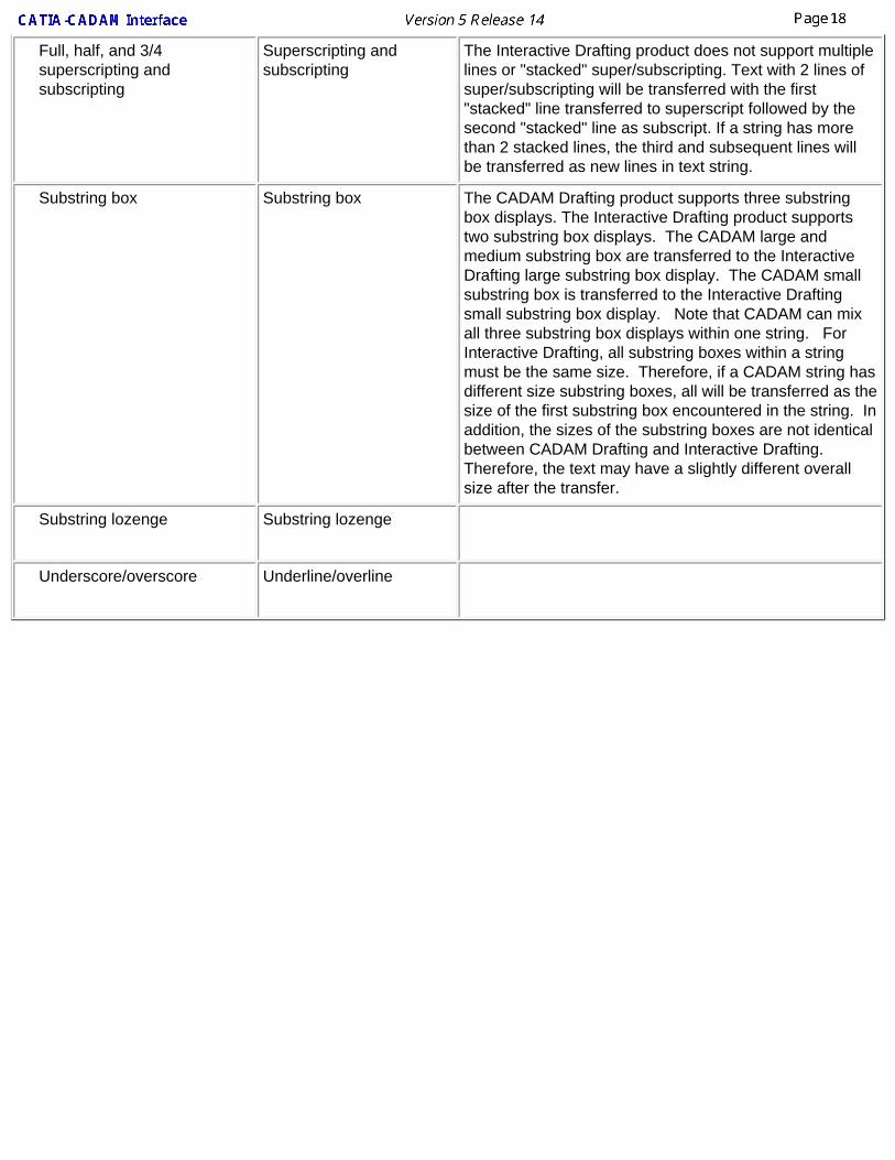
Full, half, and 3/4 superscripting and subscripting
Superscripting and subscripting
The Interactive Drafting product does not support multiple lines or "stacked" super/subscripting. Text with 2 lines of super/subscripting will be transferred with the first "stacked" line transferred to superscript followed by the second "stacked" line as subscript. If a string has more than 2 stacked lines, the third and subsequent lines will be transferred as new lines in text string.
Substring box Substring box The CADAM Drafting product supports three substring box displays. The Interactive Drafting product supports two substring box displays. The CADAM large and medium substring box are transferred to the Interactive Drafting large substring box display. The CADAM small substring box is transferred to the Interactive Drafting small substring box display. Note that CADAM can mix all three substring box displays within one string. For Interactive Drafting, all substring boxes within a string must be the same size. Therefore, if a CADAM string has different size substring boxes, all will be transferred as the size of the first substring box encountered in the string. In addition, the sizes of the substring boxes are not identical between CADAM Drafting and Interactive Drafting. Therefore, the text may have a slightly different overall size after the transfer.
Substring lozenge Substring lozenge
Underscore/overscore Underline/overline
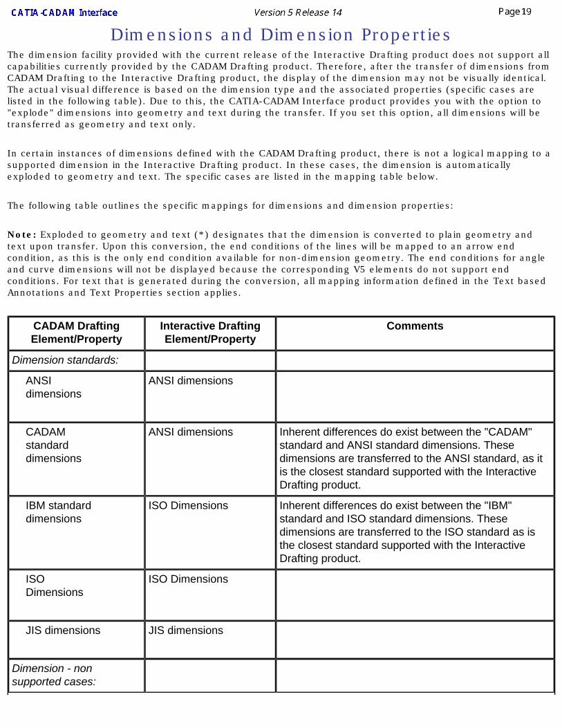
Dimensions and Dimension PropertiesThe dimension facility provided with the current release of the Interactive Drafting product does not support all capabilities currently provided by the CADAM Drafting product. Therefore, after the transfer of dimensions from CADAM Drafting to the Interactive Drafting product, the display of the dimension may not be visually identical. The actual visual difference is based on the dimension type and the associated properties (specific cases are listed in the following table). Due to this, the CATIA-CADAM Interface product provides you with the option to "explode" dimensions into geometry and text during the transfer. If you set this option, all dimensions will be transferred as geometry and text only.
In certain instances of dimensions defined with the CADAM Drafting product, there is not a logical mapping to a supported dimension in the Interactive Drafting product. In these cases, the dimension is automatically exploded to geometry and text. The specific cases are listed in the mapping table below.
The following table outlines the specific mappings for dimensions and dimension properties:
Note: Exploded to geometry and text (*) designates that the dimension is converted to plain geometry and text upon transfer. Upon this conversion, the end conditions of the lines will be mapped to an arrow end condition, as this is the only end condition available for non-dimension geometry. The end conditions for angle and curve dimensions will not be displayed because the corresponding V5 elements do not support end conditions. For text that is generated during the conversion, all mapping information defined in the Text based Annotations and Text Properties section applies.
CADAM Drafting Element/Property
Interactive Drafting Element/Property
Comments
Dimension standards:
ANSI dimensions
ANSI dimensions
CADAM standard dimensions
ANSI dimensions Inherent differences do exist between the "CADAM" standard and ANSI standard dimensions. These dimensions are transferred to the ANSI standard, as it is the closest standard supported with the Interactive Drafting product.
IBM standard dimensions
ISO Dimensions Inherent differences do exist between the "IBM" standard and ISO standard dimensions. These dimensions are transferred to the ISO standard as is the closest standard supported with the Interactive Drafting product.
ISO Dimensions
ISO Dimensions
JIS dimensions JIS dimensions
Dimension - non supported cases:
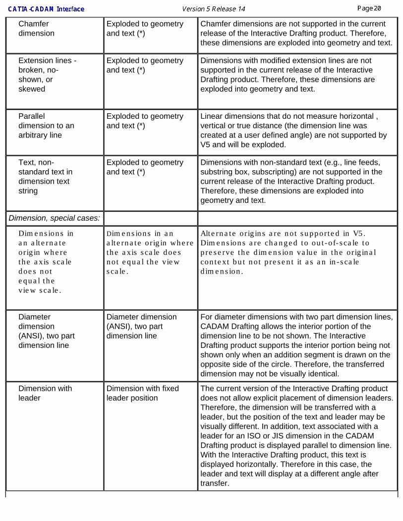
Chamfer dimension
Exploded to geometry and text (*)
Chamfer dimensions are not supported in the current release of the Interactive Drafting product. Therefore, these dimensions are exploded into geometry and text.
Extension lines - broken, no-shown, or skewed
Exploded to geometry and text (*)
Dimensions with modified extension lines are not supported in the current release of the Interactive Drafting product. Therefore, these dimensions are exploded into geometry and text.
Parallel dimension to an arbitrary line
Exploded to geometry and text (*)
Linear dimensions that do not measure horizontal , vertical or true distance (the dimension line was created at a user defined angle) are not supported by V5 and will be exploded.
Text, non-standard text in dimension text string
Exploded to geometry and text (*)
Dimensions with non-standard text (e.g., line feeds, substring box, subscripting) are not supported in the current release of the Interactive Drafting product. Therefore, these dimensions are exploded into geometry and text.
Dimension, special cases:
Dimensions in an alternate origin where the axis scale does not equal the view scale.
Dimensions in an alternate origin where the axis scale does not equal the view scale.
Alternate origins are not supported in V5. Dimensions are changed to out-of-scale to preserve the dimension value in the original context but not present it as an in-scale dimension.
Diameter dimension (ANSI), two part dimension line
Diameter dimension (ANSI), two part dimension line
For diameter dimensions with two part dimension lines, CADAM Drafting allows the interior portion of the dimension line to be not shown. The Interactive Drafting product supports the interior portion being not shown only when an addition segment is drawn on the opposite side of the circle. Therefore, the transferred dimension may not be visually identical.
Dimension with leader
Dimension with fixed leader position
The current version of the Interactive Drafting product does not allow explicit placement of dimension leaders. Therefore, the dimension will be transferred with a leader, but the position of the text and leader may be visually different. In addition, text associated with a leader for an ISO or JIS dimension in the CADAM Drafting product is displayed parallel to dimension line. With the Interactive Drafting product, this text is displayed horizontally. Therefore in this case, the leader and text will display at a different angle after transfer.
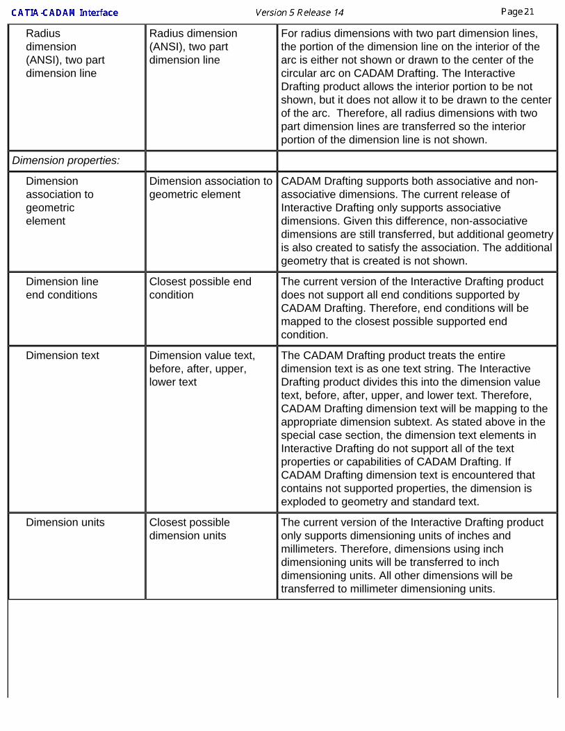
Radius dimension (ANSI), two part dimension line
Radius dimension (ANSI), two part dimension line
For radius dimensions with two part dimension lines, the portion of the dimension line on the interior of the arc is either not shown or drawn to the center of the circular arc on CADAM Drafting. The Interactive Drafting product allows the interior portion to be not shown, but it does not allow it to be drawn to the center of the arc. Therefore, all radius dimensions with two part dimension lines are transferred so the interior portion of the dimension line is not shown.
Dimension properties:
Dimension association to geometric element
Dimension association to geometric element
CADAM Drafting supports both associative and non-associative dimensions. The current release of Interactive Drafting only supports associative dimensions. Given this difference, non-associative dimensions are still transferred, but additional geometry is also created to satisfy the association. The additional geometry that is created is not shown.
Dimension line end conditions
Closest possible end condition
The current version of the Interactive Drafting product does not support all end conditions supported by CADAM Drafting. Therefore, end conditions will be mapped to the closest possible supported end condition.
Dimension text Dimension value text, before, after, upper, lower text
The CADAM Drafting product treats the entire dimension text is as one text string. The Interactive Drafting product divides this into the dimension value text, before, after, upper, and lower text. Therefore, CADAM Drafting dimension text will be mapping to the appropriate dimension subtext. As stated above in the special case section, the dimension text elements in Interactive Drafting do not support all of the text properties or capabilities of CADAM Drafting. If CADAM Drafting dimension text is encountered that contains not supported properties, the dimension is exploded to geometry and standard text.
Dimension units Closest possible dimension units
The current version of the Interactive Drafting product only supports dimensioning units of inches and millimeters. Therefore, dimensions using inch dimensioning units will be transferred to inch dimensioning units. All other dimensions will be transferred to millimeter dimensioning units.
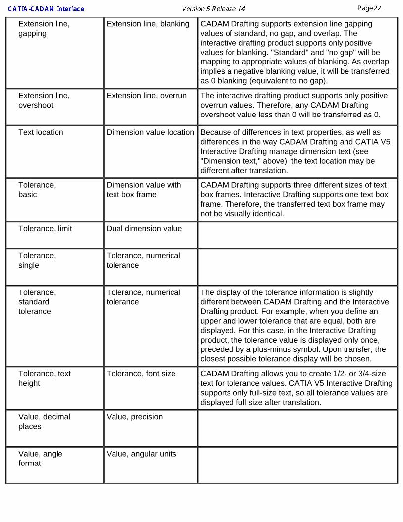
Extension line, gapping
Extension line, blanking CADAM Drafting supports extension line gapping values of standard, no gap, and overlap. The interactive drafting product supports only positive values for blanking. "Standard" and "no gap" will be mapping to appropriate values of blanking. As overlap implies a negative blanking value, it will be transferred as 0 blanking (equivalent to no gap).
Extension line, overshoot
Extension line, overrun The interactive drafting product supports only positive overrun values. Therefore, any CADAM Drafting overshoot value less than 0 will be transferred as 0.
Text location Dimension value location Because of differences in text properties, as well as differences in the way CADAM Drafting and CATIA V5 Interactive Drafting manage dimension text (see "Dimension text," above), the text location may be different after translation.
Tolerance, basic
Dimension value with text box frame
CADAM Drafting supports three different sizes of text box frames. Interactive Drafting supports one text box frame. Therefore, the transferred text box frame may not be visually identical.
Tolerance, limit Dual dimension value
Tolerance, single
Tolerance, numerical tolerance
Tolerance, standard tolerance
Tolerance, numerical tolerance
The display of the tolerance information is slightly different between CADAM Drafting and the Interactive Drafting product. For example, when you define an upper and lower tolerance that are equal, both are displayed. For this case, in the Interactive Drafting product, the tolerance value is displayed only once, preceded by a plus-minus symbol. Upon transfer, the closest possible tolerance display will be chosen.
Tolerance, text height
Tolerance, font size CADAM Drafting allows you to create 1/2- or 3/4-size text for tolerance values. CATIA V5 Interactive Drafting supports only full-size text, so all tolerance values are displayed full size after translation.
Value, decimal places
Value, precision
Value, angle format
Value, angular units

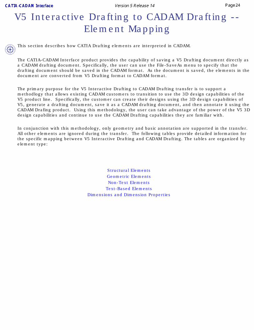
V5 Interactive Drafting to CADAM Drafting -- Element Mapping
This section describes how CATIA Drafting elements are interpreted in CADAM.
The CATIA-CADAM Interface product provides the capability of saving a V5 Drafting document directly as a CADAM drafting document. Specifically, the user can use the File-SaveAs menu to specify that the drafting document should be saved in the CADAM format. As the document is saved, the elements in the document are converted from V5 Drafting format to CADAM format.
The primary purpose for the V5 Interactive Drafting to CADAM Drafting transfer is to support a methodlogy that allows existing CADAM customers to transition to use the 3D design capabilities of the V5 product line. Specifically, the customer can create their designs using the 3D design capabilities of V5, generate a drafting document, save it as a CADAM drafting document, and then annotate it using the CADAM Drafing product. Using this methodology, the user can take advantage of the power of the V5 3D design capabilities and continue to use the CADAM Drafting capabilities they are familiar with.
In conjunction with this methodology, only geometry and basic annotation are supported in the transfer. All other elements are ignored during the transfer. The following tables provide detailed information for the specific mapping between V5 Interactive Drafting and CADAM Drafting. The tables are organized by element type:
Structural ElementsGeometric ElementsNon-Text Elements
Text-Based ElementsDimensions and Dimension Properties
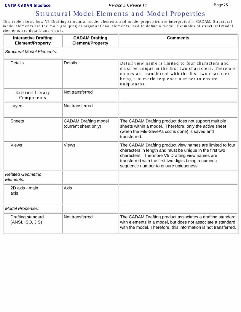
Structural Model Elements and Model PropertiesThis table shows how V5 Drafting structural model elements and model properties are interpreted in CADAM. Structural model elements are the main grouping or organizational elements used to define a model. Examples of structural model elements are details and views.
Interactive Drafting Element/Property
CADAM Drafting Element/Property
Comments
Structural Model Elements:
Details Details Detail view name is limited to four characters and must be unique in the first two characters. Therefore names are transferred with the first two characters being a numeric sequence number to ensure uniqueness.
External Library Components
Not transferred
Layers Not transferred
Sheets CADAM Drafting model (current sheet only)
The CADAM Drafting product does not support multiple sheets within a model. Therefore, only the active sheet (when the File-SaveAs ccd is done) is saved and transferred.
Views Views The CADAM Drafting product view names are limited to four characters in length and must be unique in the first two characters. Therefore V5 Drafting view names are transferred with the first two digits being a numeric sequence number to ensure uniqueness.
Related Geometric Elements:
2D axis - main axis
Axis
Model Properties:
Drafting standard (ANSI, ISO, JIS)
Not transferred The CADAM Drafting product associates a drafting standard with elements in a model, but does not associate a standard with the model. Therefore, this information is not transferred.
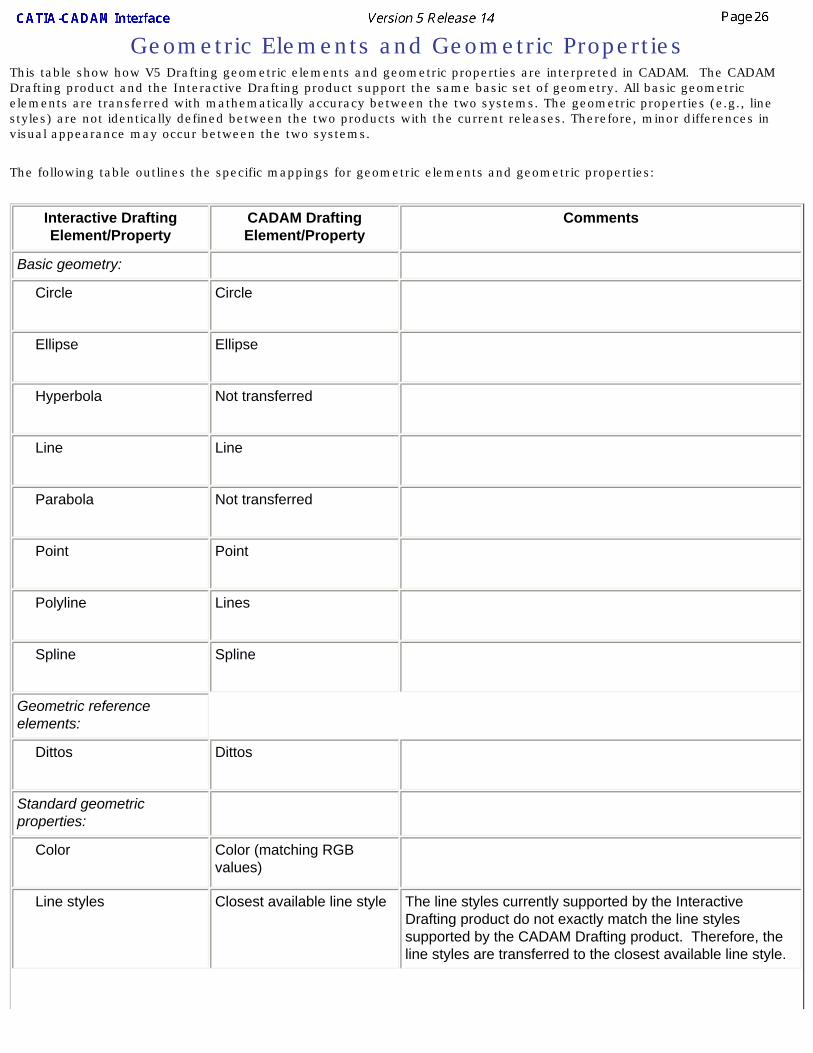
Geometric Elements and Geometric PropertiesThis table show how V5 Drafting geometric elements and geometric properties are interpreted in CADAM. The CADAM Drafting product and the Interactive Drafting product support the same basic set of geometry. All basic geometric elements are transferred with mathematically accuracy between the two systems. The geometric properties (e.g., line styles) are not identically defined between the two products with the current releases. Therefore, minor differences in visual appearance may occur between the two systems.
The following table outlines the specific mappings for geometric elements and geometric properties:
Interactive Drafting Element/Property
CADAM Drafting Element/Property
Comments
Basic geometry:
Circle Circle
Ellipse Ellipse
Hyperbola Not transferred
Line Line
Parabola Not transferred
Point Point
Polyline Lines
Spline Spline
Geometric reference elements:
Dittos Dittos
Standard geometric properties:
Color Color (matching RGB values)
Line styles Closest available line style The line styles currently supported by the Interactive Drafting product do not exactly match the line styles supported by the CADAM Drafting product. Therefore, the line styles are transferred to the closest available line style.
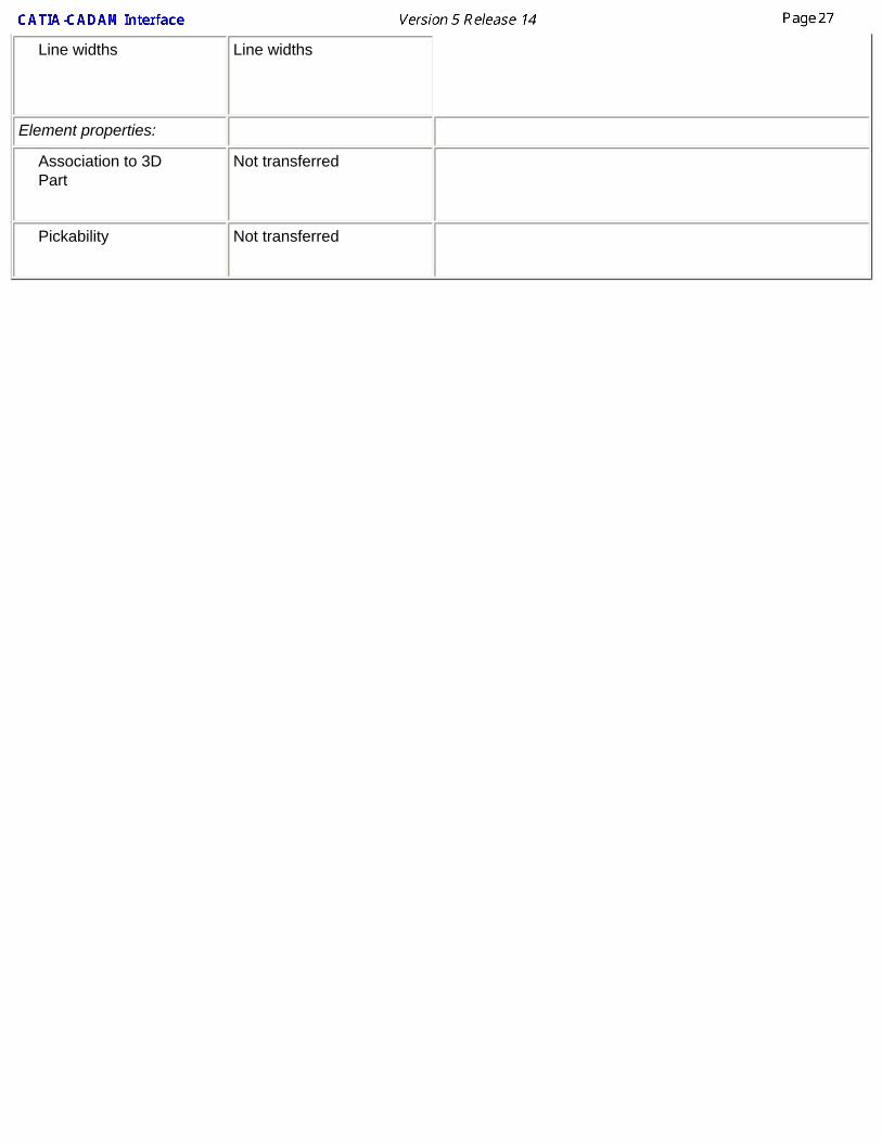
Line widths Line widths
Element properties:
Association to 3D Part
Not transferred
Pickability Not transferred
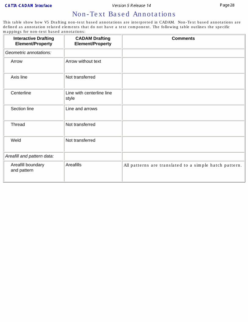
Non-Text Based AnnotationsThis table show how V5 Drafting non-text based annotations are interpreted in CADAM. Non-Text based annotations are defined as annotation related elements that do not have a text component. The following table outlines the specific mappings for non-text based annotations:
Interactive Drafting Element/Property
CADAM Drafting Element/Property
Comments
Geometric annotations:
Arrow Arrow without text
Axis line Not transferred
Centerline Line with centerline line style
Section line Line and arrows
Thread Not transferred
Weld Not transferred
Areafill and pattern data:
Areafill boundary and pattern
Areafills All patterns are translated to a simple hatch pattern.
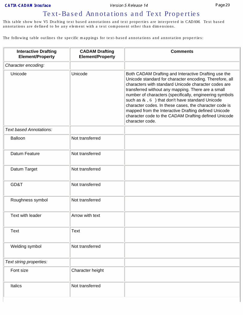
Text-Based Annotations and Text PropertiesThis table show how V5 Drafting text based annotations and text properties are interpreted in CADAM. Text based annotations are defined to be any element with a text component other than dimensions.
The following table outlines the specific mappings for text-based annotations and annotation properties:
Interactive Drafting Element/Property
CADAM Drafting Element/Property
Comments
Character encoding:
Unicode Unicode Both CADAM Drafting and Interactive Drafting use the Unicode standard for character encoding. Therefore, all characters with standard Unicode character codes are transferred without any mapping. There are a small number of characters (specifically, engineering symbols such as & , 6 ) that don't have standard Unicode character codes. In these cases, the character code is mapped from the Interactive Drafting defined Unicode character code to the CADAM Drafting defined Unicode character code.
Text based Annotations:
Balloon Not transferred
Datum Feature Not transferred
Datum Target Not transferred
GD&T Not transferred
Roughness symbol Not transferred
Text with leader Arrow with text
Text Text
Welding symbol Not transferred
Text string properties:
Font size Character height
Italics Not transferred
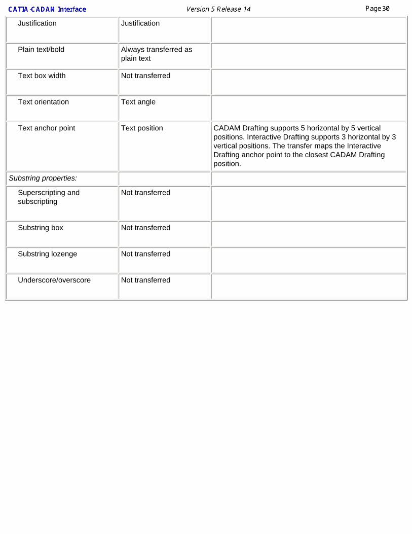
Justification Justification
Plain text/bold Always transferred as plain text
Text box width Not transferred
Text orientation Text angle
Text anchor point Text position CADAM Drafting supports 5 horizontal by 5 vertical positions. Interactive Drafting supports 3 horizontal by 3 vertical positions. The transfer maps the Interactive Drafting anchor point to the closest CADAM Drafting position.
Substring properties:
Superscripting and subscripting
Not transferred
Substring box Not transferred
Substring lozenge Not transferred
Underscore/overscore Not transferred
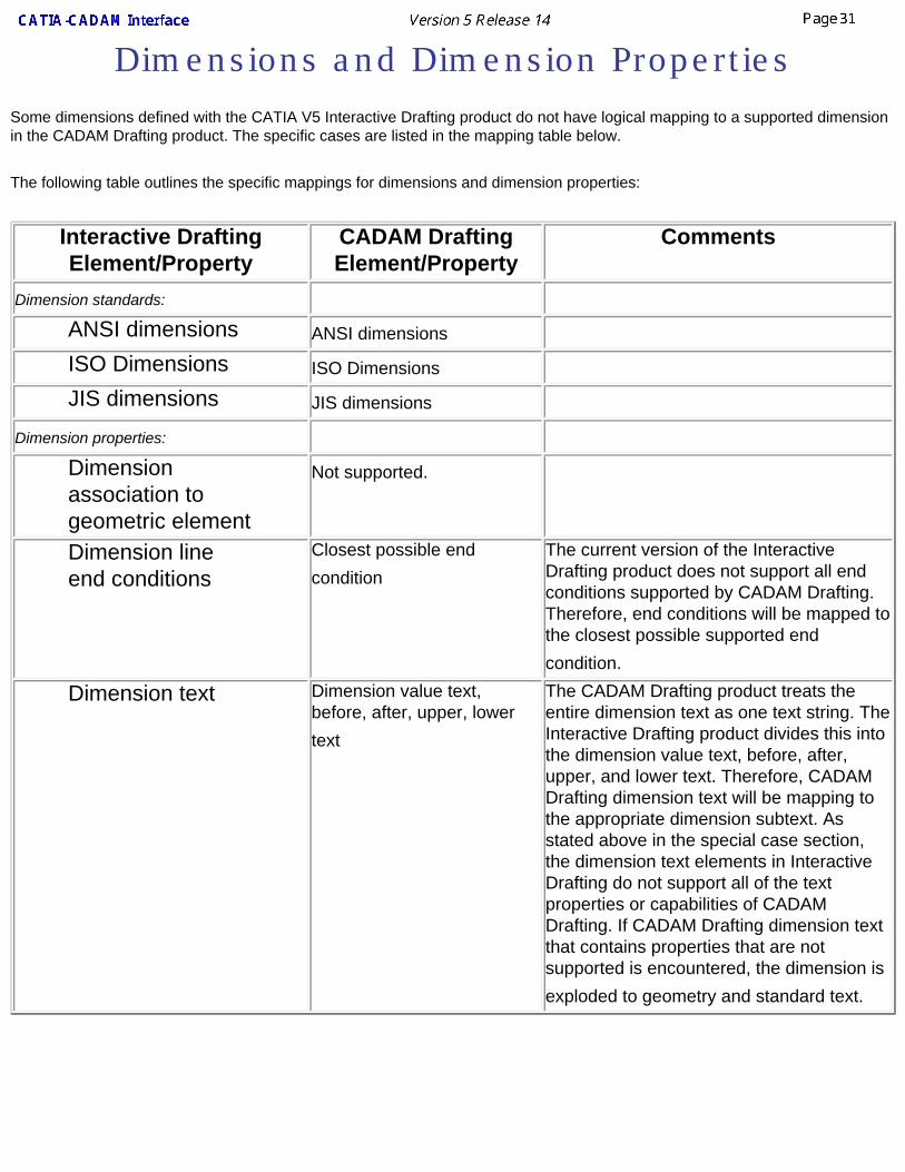
Dimensions and Dimension PropertiesSome dimensions defined with the CATIA V5 Interactive Drafting product do not have logical mapping to a supported dimension in the CADAM Drafting product. The specific cases are listed in the mapping table below.
The following table outlines the specific mappings for dimensions and dimension properties:
Interactive Drafting Element/Property
CADAM Drafting Element/Property
Comments
Dimension standards: ANSI dimensions ANSI dimensions
ISO Dimensions ISO Dimensions JIS dimensions JIS dimensions
Dimension properties: Dimension association to geometric element
Not supported.
Dimension line end conditions
Closest possible end condition
The current version of the Interactive Drafting product does not support all end conditions supported by CADAM Drafting. Therefore, end conditions will be mapped to the closest possible supported end condition.
Dimension text Dimension value text, before, after, upper, lower text
The CADAM Drafting product treats the entire dimension text as one text string. The Interactive Drafting product divides this into the dimension value text, before, after, upper, and lower text. Therefore, CADAM Drafting dimension text will be mapping to the appropriate dimension subtext. As stated above in the special case section, the dimension text elements in Interactive Drafting do not support all of the text properties or capabilities of CADAM Drafting. If CADAM Drafting dimension text that contains properties that are not supported is encountered, the dimension is exploded to geometry and standard text.

User Tasks The tasks for creating documents using the CATIA-CADAM Interface product are explained here.
Setting OptionsOpening a CCD Model in V5
Saving V5 to CCDSetting System Variable to Allow V5 to CCD Translation
Preparing a CCD Model
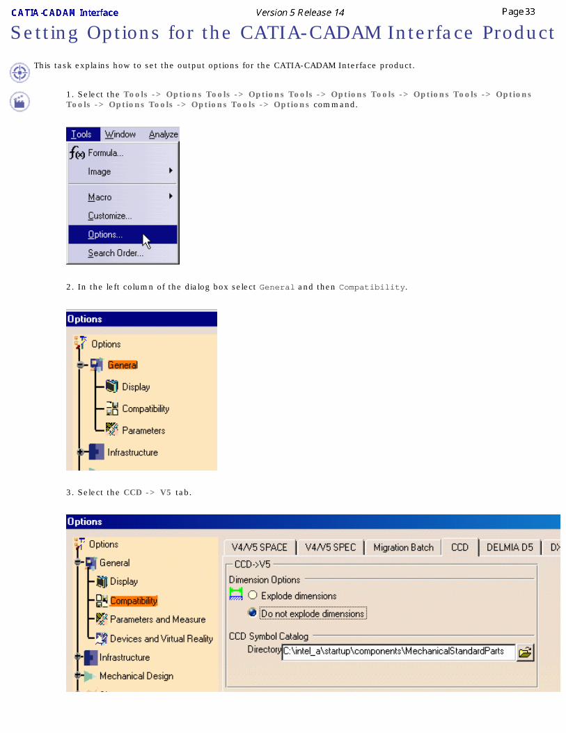
Setting Options for the CATIA-CADAM Interface Product
This task explains how to set the output options for the CATIA-CADAM Interface product.
1. Select the Tools -> Options Tools -> Options Tools -> Options Tools -> Options Tools -> Options Tools -> Options Tools -> Options Tools -> Options command.
2. In the left column of the dialog box select General and then Compatibility.
3. Select the CCD -> V5 tab.

4. Select the appropriate option.
Select Explode dimensions to change dimensions into CATIA V5 text, lines, and arcs.Select Do not explode dimensions to reproduce dimensions as CATIA V5 dimensions.
5. Select the Directory field. Key in the location of the CCD symbol table model V5 catalogs. You can also click the Folder button to navigate to the directory.

Opening a CADAM Drafting Model in V5
This task explains how to open a CADAM Drafting model in CATIA Version 5.
1. Click the Open icon or select the File->Open... command.
2. In the File Selection dialog box, navigate to the appropriate folder.
You can filter the list of files to display only CADAM Drafting models by defining Files of type: cdd (*.cdd)
3. Select the model.
Saving a V5 Drafting Document as a CADAM Drafting Model
This task explains how to save a V5 Drafting document as a CADAM Drafting model..
1. Select the File->SaveAs... command.
2. Define CADAM as the file type by defining Save as type: cddcdd.
3. In the SaveAs dialog box, navigate to the appropriate folder.
4. Click the Save button to save the document as a CADAM model.
Setting System Variable to Allow V5 to CCD Translation
Your installation may not allow you to translate V5 documents into CCD format. CATIA V5 requires a CCD license to translate V5 documents into CCD format.
If you have a license and you still cannot translate V5 documents into CCD format, you may need to enter a system variable to establish the license relationships. The system variable should be entered at the Command Line and is:
DRW_CCDTOV5 = 1
Refer this section to your system administrator.
Preparing a CADAM Drafting Model for Translation
In order to produce the best possible results when moving a CADAM Drafting model to CATIA V5, you should be aware that:
● PROFESSIONAL CADAM models (D_modelID files) are not supported.Recommendation: Translate the D_modelID files to the .ccd format before moving them to CATIA V5.See the CATIA-CADAM Drafting Installation Guide for instructions.
● Only single-model files (.cdd files) are supported. Overlay parent models (.cdo files) are not supported in this release.
● Only 2D drafting elements are supported. Other types of elements (e.g., 3D and NC) are not supported.
● Reference entities are not supported.Recommendation: Whenever possible (and practical), place reference entities directly in the desired model. Use the Cut/copy/paste facility to accomplish this quickly.
● Symbol table symbols are not supported.Recommendation: Convert all symbol table symbols to geometry before you try to translate the model. To do this, follow these steps:
1. Call the model.2. Select function key SYMBOL.3. Select /SPECIAL/ + /CONVERT/ + /CONVERT ALL/.4. Select YN.5. File the model.
● You should overfile or explicitly pack the model (using function key SHOW, menu option /PACK/) to minimize the space needed for the model, as well as the time needed to process the translation.
Glossary
A
accelerator key See shortcut key.
access bar See desktop toolbar.
access key The key that corresponds to an underlines letter on a menu or control (also referred to as a mnemonic access key).
accessibility Designing software to be usable and accessible to the widest range of users, including users with disabilities.
active The state when an object is the focus of user input and its operations are available.
active end The ending point for a selected range of objects. It is usually established at the object logically nearest the hot spot of the pointer when a user releases a mouse button. Compare anchor point.
active object Object currently being edited.active window The window in which a user is currently working or directing input. An active
window is typically at the top of the Z order and is distinguished by the color of its title bar. Compare inactive window.
album Collection of images you generate with the Tools -> Capture command.anchor point The starting point for a selected range of objects. An anchor point is usually
established at the object logically nearest the hot spot of the pointer when a user presses a mouse button. Compare active end.
anti-aliasing A graphic design technique that involves adding colored pixels to smooth the jagged edges of a graphic.
application window Window containing the CATIA Version 5 application.apply To commit a set of changes or pending transactions made in a secondary window,
typically without closing that window.auto-exit A text box in which the input focus automatically moves to the next control as
soon as a user types the last character.auto-joining The movement of text to fill a remaining gap after a user deletes other text.automatic scrolling A technique where a display area automatically scrolls without direct interaction
with a scroll bar.auto-repeat An event or interaction that is automatically repeated.Atu-repeat events usually
occur when a user holds down a keyboard key or presses and holds a special control (for example, scroll bar buttons).
B
background Area in document windows to which you can apply a background color.box edit A standard Microsoft Windows interface control that provides a discrete area for
entering each character. A user can also edit text within the control.
C
cancel To halt an operation or process and return to the state before it was invoked. Compare stop.
caret See insertion point.
cascading menu A menu that is a submenu of a menu item (also referred to as a hierarchical menu, child menu, or submenu).
check box A standard Windows control that displays a setting, either checked (set) or unchecked (not set). Compare option button.
child menu See cascading menu.
child window A document window used within an MDI window. See also multiple document interface.
click (v.) To position the pointer over an object and then press and release a mouse button. See also press.(n.) The act of clicking.
clipboard The area of storage for objects, data or their references after a user carries out a Cut or Copy command.
clipboard format The data format of a memory object on the clipboard. Applications can use the standard clipboard formats provided by Windows or register their own custom formats. A clipboard format is identified by a unique, unsigned integer value, called the "format name."
clipping Depth effect for viewing parts or all of a 3D object between two planes.close To remove a window.character set A character is any symbol used for the organization, control, or representation of
data. A group of such symbols used to describe a particular language. Each language (or group of languages) has its character set
code page A collection of characters that make up character set. See also locale.
code set A code page (or code set) is a table mapping a given character (from a given character set) to a hexadecimal code position, or code point, for that code page. It contains the encoding values for a character set or several character sets. The encoding values in a code set provide the interface between the system and its input and output devices.
collection A set of objects that shares some common aspect.column heading A standard Windows control that can be used to provide interactive column titles
for a list.combo box A standard Windows control that combines a text box and interdependent list
box.command button A standard Windows control that initiates a command or sets an option (also
referred to as a push button).composite A set or group of objects whose aggregation is recognized as an object itself (for
example, characters in a paragraph, named range of cells in a spreadsheet, or a grouped set of drawing objects).
constraint A relationship between a set of objects, such that making a change to one object affects another object in the set.
container An object that holds other objects.context-sensitive Help Information about an object and its current condition. It answers the questions
"What is this" and "Why would I want to use it?" Compare reference Help and task-oriented Help.
contextual Specific to the conditions in which something exists or occurs.
contextual menu A menu that is displayed at the location of a selected object (also referred to as a shortcut menu). The menu contains the commands that are contextually relevant to the selection, and the most frequently used. You display the contextual menu by right-clicking.
contextual window A secondary window with no title bar that is displayed next to an object; it provides contextual information about that object.
contiguous selection A selection that consists of a set of objects that are logically sequential or adjacent to each other (also referred to as range selection). Compare disjoint selection.
control An object that enables user interaction or input, often to initiate an action, display information, or set values.
current State of an object when selected.cursor A generic term for the visible indication of where a user's interaction will occur.
See also input focus, insertion point, and pointer.
D
data-centric design A design in which users interact with their data directly without having to first start an appropriate editor or application.
data link A link that propagates a value between two objects or locations.default An operation or value that the system or application assumes, unless a user
makes an explicit choice.default button The command button that is invoked when a user presses the ENTER key. A
default button typically appears in a secondary window.desktop The visual work area that fills the display. The desktop is also a container and can
be used as a convenient location to place objects stored in the file system.desktop toolbar A toolbar that docks to the desktop, similar to the taskbar. See also taskbar.
dialog base unit A device-independent measure to use for layout. One horizontal unit is equal to one-fourth of the average character width for the current system font. One vertical unit is equal to one-eighth of an average character height for the current system font.
dialog box A secondary window that gathers additional information from a user. A dialog box usually contains one or more controls, such as buttons, list boxes, combo boxes, and edit boxes, with which the user enters text, chooses options, or directs the action of the command. Compare message box, palette window, and property sheet.
dimmed See unavailable.
disjoint selection A selection that consists of a set of objects that are not logically sequential or physically adjacent to each other. Compare contiguous selection. See also extended selection.
dock To manipulate an interface element, such as a toolbar, such that is aligns itself with the edge of another interface element, typically a window or pane.
document A common unit of data (typically a file) used in user tasks and exchanged between users. When saved on disk, a document is given a unique filename by which it can be retrieved.
document window A window that provides a primary view of a document (typically its content).double-click (v.) To press an release a mouse button twice in rapid succession.
(n.) The act of double-clicking.duplicate Performs mirroring or pattern operations on an active object.
E
edit field See text box.
Edit menu A common drop-down menu that includes general purpose commands for editing the current object, such as Cut, Copy, and Paste.
ellipsis The "..." suffix added to a menu item or button label to indicate that the command requires additional information to be completed. When a user chooses the command, a dialog box is usually displayed for the user input of this additional information.
embedded object See OLE embedded object.
enter (v.) To type a character from the keyboard.(n.) A classification of an object based on its characteristics, behavior, and attributes.
explicit selection A selection that a user intentionally performs with an input device. Compare implicit selection.
extended selection A section technique that is optimized for the selection of a single object or single range using contiguous selection techniques (that is, canceling any existing selection when a new selection is made). However, it also supports modifying an existing selection using disjoint selection techniques. See also disjoint selection.
extended selection list box A list box that supports multiple selection, but is optimized for a selection of a single object or single range. See extended selection and list box. Compare multiple selection list box.
F
filter Tool for organizing elements of V4 model document into layers.File menu A common drop-down menu that includes commands for file operations, such as
Open, Save, and Print.font A set of attributes for text characters.font size The size of a font, typically represented in points.
G
geometry area Area of a document window in which application data are displayed and edited.glyph A generic term used to refer to any graphic or pictorial image that can be used on
a button or in a message box. Compare icon.
group box A standard Windows control that groups a set of controls.
H
handle An interface element added to an object that provides a control point for moving, sizing, reshaping, or other operations pertaining to that object.
Help menu A common drop-down menu that includes commands that provide access to Help information or other forms of user assistance. See also context-sensitive Help, and task-oriented Help.
heterogeneous selection A selection that includes objects with different properties or type. Compare homogeneous selection.
hierarchical menu See cascading menu.
hold down To continue pressing a keyboard key, or mouse button.homogeneous selection A selection that includes objects with the same properties or type. Compare
heterogeneous selection.
hot spot The specific portion of the pointer (or pointing device) that defines the exact location, or object, to which a user is pointing.
hot zone The interaction area of a particular object or location with which a pointer or pointing device's hot spot must come in contact.
I
icon A pictorial representation of an object. Compare glyph.
implicit selection A selection that is the result of inference or the context of some other operation. See also explicit selection.
inactive The state of an object which it is not the focus of a user's input.inactive window A window in which a user's input is not currently being directed. An inactive
window is typically distinguished by the color of its title bar. Compare active window.
in-place activation The ability to edit an OLE embedded object in place, without opening it into its own window.
input focus The location where the user is currently directing input.input focus appearance The visual display of a control or other object that indicates when it has the input
focus.insertion point The location where text or graphics will be inserted (also referred to as the
caret). Also used for text box controls to indicate input focus.inside-out activation A technique that allows a user to directly interact with the content of an OLE
embedded object without executing an explicit activation command. Compare outside-in activation.
interoperability● Ability to exchange data between CATIA Version 4 and CATIA Version 5.
● Ability to exchange CATIA Version 5 data between CATIA Version 5 workshops
● Ability to exchange data between CATIA Version 5 and OLE-compliant applications.
J
jump A special form of a link that navigates to another location (also referred to as a hyperlink).
L
label The text (or graphic) that identifies a control (also referred to as a caption).landscape An orientation where the long dimension of a rectangular area (for example,
screen or paper) is horizontal.link (v.) To form a connection between two objects.
(n)) A reference to an object that is linked to another object. See also OLE linked object.
link path The descriptive form of referring to the location of a link source (also referred to as a moniker).
list box A standard Windows control that displays a list of choices. See also extended selection list box.
list view A standard Windows list box control that displays a set of objects. The control also supports different views and drag and drop.
locale A part of a user's environment dedicated to international data to define conventions for a specified culture, such as time formatting, numeric formatting, and character classification, conversion, and collation.
localization The process of adapting software for different countries, languages, or cultures.
M
marquee See region selection and bounding outline.
maximize To make a window its largest size. See also minimize.
MDI See multiple document interface.
menu A list of textual or graphical choices from which a user can choose. See also contextual menu.
menu bar A horizontal bar at the top of a window, below the title bar, that contains menus.menu button A command button that displays a menu.menu item A choice on a menu.menu title A text or graphic label that designates a particular menu. For drop-down menus,
the titles is the entry in the menu bar; for cascading menus the menu title is the name of its parent menu item.
message box A secondary window that is displayed to inform a user about a particular condition. Compare dialog box, palette window, and property sheet.
minimize To minimize the size of a window: in some cases, this means to hide the window. See also maximize.
mirror An operation creating a 3D object by duplicating an initial object. The duplication is defined by symmetry.
mnemonic See access key.
modal A restrictive or limiting interaction because of operating in a mode. Modal often describes a secondary window that restricts a user's interaction with other windows. A secondary window can be modal with respect to its primary window or to the entire system. Compare modeless.
mode A particular state of interactions, often exclusive in some way to other forms of interactions.
model CATIA Version 4 model.model document Document containing a CATIA Version 4 model.
modeless Not restrictive or limiting interaction. Modeless often describes a secondary window that does not restrict a user's interaction with other windows. Compare modal.
modifier key A keyboard key that, when pressed, (and held), changes the actions of input.moniker See link path.
most recently used List of most recently used files (MRU) located in the File menu for easy access.mouse A commonly used input device that has one or more buttons used to interact with
a computer. It is also used as a generic term to include other pointing devices that operate similarly (for example, trackballs and headpointers).
multiple documentinterface (MDI)
A technique for managing a set of windows whereby documents are opened into windows (sometimes called child windows) that are constrained to a single primary (parent) window. See child window, and parent window.
multiple selection list box A list box that is optimized for making multiple, independent selections. Compare extended selection list box and single selection list box.
N
network license A license maintained on a network license server for use upon request by a License Use Runtime (LUM) client. Compare nodelocked license.
non-default drag and drop A drag (transfer) operation whose interpretation is determined by a user's choice of command. These commands are included in a pop-up menu displayed at the destination when the object is dropped.
nodelocked license A type of license locked to a specific node, so that the product can be used only at that node. The nodelocked license is installed on the computer for which it was created. Compare network license.
O
object An entity or component identifiable by a user that can be distinguished by its properties, operations, and relationships.
OLE Object Linking and Embedding. The name that describes the technology and interface for implementing support for object interaction.
OLE embeddedobject
A data object that retains the original editing and operating functionality of the application that created it, while physically residing in another document.
OLE linked object An object that represents or provides an access point to another object that resides at another location in the same container or a different, separate container. See also link.
operation A generic term that refers to the actions that can be done to or with an object.option button A standard Windows control that allows a user to select from a fixed set of
mutually exclusive choices (also referred to as a radio button). Compare check box.
outside-in activation A technique that requires a user to perform an explicit activation command to interact with the content of an OLE embedded object. Compare inside-out activation.
P
package An OLE encapsulation of a file so that it can be embedded in an OLE container.palette window A modeless secondary window that displays a tool bar of other choices, such as
colors or patterns. Compare dialog box and message box. See also property sheet.
pane One of the separate areas in a split window.parent window A primary window that provides window management for a set of child windows.
See also child window and multiple document interface.
persistence The principle that the state of an object is automatically preserved.point (v.) To position the pointer over a particular object an location.
(n.) A unit of measurement for type (1 point equals approximately 1/72 inch).pointer A graphic image displayed on the screen that indicates the location of a pointing
devices (also referred to as a cursor).portrait An orientation where the long dimension of a rectangular area (for example,
screen or paper) is vertical.press To press and release a keyboard key. See also click.
preview Tool allowing you to view a document or album image prior to printing.primary window The window in which the main interaction takes place. See also secondary
window and window.
progress indicator Any form of feedback that provides the user with information about the state of a process.
progress indicator control A standard Windows control that displays the percentage of completion of a particular process as a graphical bar.
project A window or task management technique that consists of a container holding a set of objects, such that when the container is opened, the windows of the contained objects are restored to their former positions.
property Attribute or characteristic of an object that define its state, appearance, or value.property inspector A dynamic properties viewer that displays the properties of the current selection,
usually of a particular type of object. Compare property sheet.
property page A group of properties on a tabbed page or a property sheet. See also property sheet.
property sheet A secondary window that displays the properties of an object when a user chooses its Properties command. Compare dialog box. See also property page.
property sheet control A standard Windows control used to create property sheet interface.push button See command button.
R
radio button See option button.
range selection See contiguous selection.
redo Repeat the last operation.reference Help A form of online Help information that can contain conceptual and explanatory
information. Compare task-oriented Help and context-sensitive Help.
region selection A selection technique that involves dragging out a bounding outline (also referred to as a marquee) to define the selected objects.
relationship The context or way an object relates to its environment.
rich-text box A standard Windows control that is similar to a standard text box, except that it also supports individual character and paragraph properties.
right-click Click using the right mouse button (to display contextual menu).
S
scale Operation that resizes the contents of document prior to printing or previewing.scope The definition of the extent that a selection is logically independent from other
selections. For example, selections made in separate windows are typically considered to be independent of each other.
scroll To move the view of an object or information to make a different portion visible.scroll arrow button A component of a scroll bar that allows the information to be scrolled by defined
increments when the user clicks it. The direction of the arrow indicates the direction in which the information scrolls.
scroll bar A standard Windows control that supports scrolling.scroll bar shaft The component of a scroll bar that provides the visual context for the scroll box.
Clicking (or tapping) in the scroll bar shaft scrolls the information by a screenful. See also scroll box.
scroll box A component of a scroll bar that indicates the relative position (and optionally the proportion) of the visible information relative to the entire amount of information. The user can drag the scroll box to view areas of information not currently visible. See also scroll bar shaft.
secondary window A window that provides information or supplemental interaction related to objects in a primary window.
section view 3D view of a cross-section generated using a plane.select To identify one or more objects upon which an operation can be performed.selection An object or set of objects hat have been selected.selection appearance The visual display of an object when it has been selected.selection handle A graphical control point of an object that provides direct manipulation support
for operations of that object, such as moving, sizing, or scaling.selection set A group of selected objects that you can store and retrieve.Send To Tool used for sharing document files with other users.separator An entry in a menu used to group menu items together.settings Set of setup parameters and user preferences stored in non-editable files.shell A generic term that refers to the interface that allows the user control over the
system.shortcut A generic term that refers to an action or technique that invokes a particular
command or performs an operation with less interaction than its usual method.shortcut icon A link presented as an icon that provides a user with access to another object.shortcut key A keyboard key or key combination that invokes a particular command (also
referred to as an accelerator key).shortcut menu See contextual menu.
single selection list box A list box that only supports selection of a single item in the list.size grip A special control that appears at the junction of a horizontal and vertical scroll
bar or the right end of a status bar and provides an area that a user can drag to size the lower right corner of a window.
slider A standard Windows control that displays and sets a values from a continuous range of possible values, such as brightness or volume.
specification tree Area of the document window reserved for viewing the design specifications of a part, presented in the form of a tree structure.
spin box A control composed of a text box and increment and decrement buttons that allow a user to adjust a values from a limited range of possible values.
split An operation allowing splitting 3D objects using a plane.split bar A division between panes that appears where a window has been split; the split
bar visually separates window panes.split box A special control added to a window, typically adjacent to the scroll bar, that
allows a user to split a window or adjust a window split.standard view Typical view available in 3D workshops: top, bottom, front, back, left, right,
isometric.status bar An area that allows the display of state information of the information being
viewed in the window, typically places at the bottom of a window.status bar control A standard Windows control that provides the functionality of a status bar.stop To halt a process or actions, typically without restoring the state before the
process began. Compare cancel.
submenu See cascading menu.
T
tab control A standard Windows control looks similar to a notebook or file divider and provides navigation between different pages or sections of information.
targeting To determine where pen input is directed.taskbar A special toolbar that docks on an edge of the desktop supplied by the system.
The taskbar includes the Start button, buttons for each open primary window, and a status bar.
task-oriented Help Information about the steps involved in carrying out a particular task. Compare context-sensitive Help and reference Help.
template An object that automates the creation of new objects of a particular type.text box A standard Windows control in which a user can enter an edit text (also referred
to as the edit field).thread A process that is part of a larger process or program.title bar The horizontal area at the top of a window that identifies the window. The title
bar also acts as a handle for dragging the window.toggle key A keyboard key that alternates between turning a particular operation, function,
or mode on or off.toolbar A frame or special area that contains a set of other controls.toolbar button A command button used in a toolbar (or status bar).toolbar control A standard Windows control designed with the same characteristics as the
toolbar.tooltip A standard Windows control that provides a small pop-up window that provides
descriptive text such as a label, for a control or graphic object.transfer appearance The visual feedback displayed during a transfer operation.tree control A standard Windows control that allows a set of hierarchically related objects to
be displayed as an expandable outline.
U
unavailable The state of a control or data whose normal functionality is not presently available to a user (also referred to as dimmed).
undo To reverse one operation performed on an object.user-defined view 3D view an end user can generate by customizing view parameters. The view can
be named. Also referred to as named view.
V
view toolbar Toolbar containing viewing tools.viewing tools Tools for viewing contents of current document in different ways.VRML Virtual Reality Markup Language. A vector-based language for modeling three-
dimensional environments. It sends ASCII text files over the Internet, which are translated by the VRML viewing engine at the other end. VRML complements HTML. This format is useful for viewing CATIA Version 5 data using a Web browser.
W
well control A control that is used to display color or pattern choices, typically used like an option button.
window A standard Windows object that displays information. A window is a separately controllable area of the screen that typically has a rectangular border. See also primary window and secondary window.
wizard A form of user assistance that automates a task through a dialog with the user.wordwrap The convention where, as a user enters text, existing text is automatically moved
from the end of a line to the next line.workbench Set of tools for completing specific tasks. Each type of document can be edited
with a document-specific set of tools.workspace A window or task management technique that consists of a container holding a
set of objects, where the windows of the contained objects are constrained to a parent window. Similar to the multiple document interface, except that the window displayed within the parent window are of objects that are also contained in the workspace.
writing tool A standard Windows pen interface control that supports text editing.
Z
Z order The layered relationship of a set of objects, such as windows, on the display screen.
Index
CCADAM Drafting model
opening in V5
preparing for translation
CATIA V5 document, saving as a CADAM Drafting model
Ddimensions, setting option to explode
Gguidelines for preparing a CADAM Drafting model for translation
Mmapping CADAM Drafting elements to V5 Drafting elements mapping table (CADAM to V5)
dimensions and dimension properties
geometric elements and geometric properties
non-text based annotations
structural model elements and model properties
text-based annotations and text properties mapping table (V5 to CADAM)
dimensions and dimension properties
geometric elements and geometric properties
non-text based annotations
structural model elements and model properties
text-based annotations and text properties
mapping V5 Drafting elements to CADAM Drafting elements
methodology, explained
Ooptions, setting
overlay parent models, support status
PPROFESSIONAL CADAM model, support status
Rreference entities, support status
Ssaving a CATIA V5 document as a CADAM Drafting model
setting options
symbol tables, support status
system variable for V5 to CCD translation