cathode ray oscilloscope introduction
DESCRIPTION
Cathode Ray Oscilloscope Introduction. Look and play Read instructions Break into smaller parts Decide on a simple measurement Increase your level of difficulty Record pathway. How you got there. Store directions and short-cuts. Cathode Ray Oscilloscope. - PowerPoint PPT PresentationTRANSCRIPT
1
Cathode Ray Oscilloscope Introduction
• Look and play
• Read instructions
• Break into smaller parts
• Decide on a simple measurement
• Increase your level of difficulty
• Record pathway. How you got there.
• Store directions and short-cuts

2
Cathode Ray Oscilloscope• Popular instrument to show time, voltage
both DC and AC. Shows Volts / Time.• Display waveforms. Spectrum scope shows volts to Frequency
• Cathode (-ve ) is heated, emits electrons, accelerated toward a (+ve) fluorescent screen. Intensity grid, Focus grid, Accelerating anode. (Electron gun)
• Horizontal deflection plates.
• Vertical deflection plates
3
Cathode Ray Oscilloscope• When electrons hit the screen the phosphor is excited and
emits light.
• Persistence. How long the display glows.• May need to reduce ambient light for older instruments.
• Connect a signal to Vertical deflection plate.
• At same time a voltage that increases linearly with time (Ramp) is applied to the Horizontal deflection plates.
4
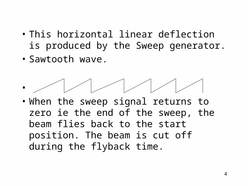
• This horizontal linear deflection is produced by the Sweep generator.
• Sawtooth wave.
•
• When the sweep signal returns to zero ie the end of the sweep, the beam flies back to the start position. The beam is cut off during the flyback time.
5
CROs
• The display is made to appear stationary.
• This controlled by your adjustment settings.
• The eye sees a waveform.
• X is <----> Horizontal
• Y is ^ Vertical Height of trace
6
• The signal is amplified by the vertical amplifier, applied to the vertical plates.
• A portion of the vertical amp signal is applied to the Sweep Trigger.
• The sweep trigger generates a pulse coincident with a selected point in the cycle of the trigger signal.
• This pulse turns on the sweep generator initiating the sawtooth wave form.
• The sawtooth wave is amplified by the horizontal amp and applied to the horizontal deflection plates
7
• The trigger can be based on 50 (60) Hz
•
• Provision is made for an external trigger.
8
CRO Tube Controls• POWER on / off
• Scale
• Illumination
• Focus. Create spot on screen
• Intensity. Brightness (Don’t burn a spot on your screen)
9
Vertical Amp
• Position on display• Sensitivity of vertical amp Calibrated. Cal
fully clockwise.• Variable sensitivity. Continuous range between calibrated
steps.
• AC - DC - Gnd.• Selects desired coupling for incoming signal, or grounds amp
input. DC couples signal directly to amp. AC connects via a capacitor. (Blocks DC)
• Gnd = no signal. Gnd connects Y input to 0 volts. Checks
position of 0v on screen.
10
Horizontal Sweep• Sweep time / Div (or CM) Select desired
sweep rate, or admits external sig to horiz amp.
• Sweep time / Cm Variable Continuously
variable sweep rates. Cal is fully clockwise.• Position Controls horizontal position of trace.
• Horizontal variable controls attenuation of signal applied to Horz amp through Ext Horiz connector.
11
Trigger Set to Auto or normal
• Trigger selects timing of the beginning of the Horizontal sweep.
• Slope selects trigger at +ve increasing or -ve decreasing portion of signal.
• Coupling Selects whether trigger is at a specific DC or AC level.
• Source: Int from Vertical Amp
• Ext from Ext Trig Input.
• Line AC line 50 (60) HZ

12
Volts /Div switch
• Volts / Div
• Variable Fine adjustment
• these controls can have a Pull out switch position. May be 5 times mag.

13
Vertical mode
• The operation of vertical deflection plates
• Chan 1 and Chan 2 can each operate separately.
• Dual. Ch1 and Ch2 are swept alternatively.
• Why Dual? Used to measure input and Output signals of a device under test.
• Ch1 and Ch2 can be added

14
Time base• Main, Max, Min, delay.• Selects the sweep for the main mix or delay mode and also
X-Y switch
• Time/Div provides selection of sweep rates. Range of 0.1 Second, 50 to .1 mS, 50 to 0.1uS per div. Note 5,2,1, sequence.
• To determine a frequency use reciprocal.• Frequency = 1/time period (50Hz = 1/20mS)
• Time period = 1/Frequency (number of div * ?ms/div. Eg 4div*5ms/div = 20 ms)

15
Other
• Comp Test. Allows individual components to be tested. Connect via banana jacks to test resistors, capacitors, diodes, transistors, etc
• Cal delivers calibrated voltage e.g. 2v p-p 1KHz square wave for setting scale.
• GND. Earth terminal of scope
16
Connections
• Vertical Input
• Horizontal Input
• External Trigger
• Cal. Out
17
Bandwidth• A 10MHz CRO does not mean it will correctly measure
signals at 10MHz.
• Vertical Amps are not so wide-band as to amplify all signals. 10MHz is the 3dB point. A 10MHz signal of 1v will measure 0.707v on the screen.
• Clipping introduces odd order harmonics. A CRO operating near the max freq. will not show the harmonics and you
think you are reading a clean signal. • Square waves begin to look like sine waves.
• A rule of thumb is 5 times. To measure 2MHZ use a 10MHz CRO. 3 times is suitable for most Amateur work.
• For 7MHz. Times 3 = 21. Use a 20 MHz CRO.
18
Every CRO will be different
• Many instruments made for specific work.
• Beam Finder push button
• Trace rotation
• Chan 1 Vertical input. During X-Y operation this is X axis (abscissa)
• Chan 2 Vertical input Chan 2. During X-Y this becomes ordinate input.

19
And there’s more !
• Don’t worry about it
• Nothing is complex
• Just Simplicity multiplied
•
20
Operating
• Power on
• Intensity fully counter-clockwise
• Vertical centering in center of range
• Horizontal centering in center of range
• Vertical at 0.2 or 5v / div. Try a range.
• Timebase 10ms / div Change to suit.
• Play ‘till operating for you.
21
Mini exercises
• Obtain a trace
• Brightness
• Focus
• Move trace up, down.
• Move trace side ways

22
Measuring
• Voltage RMS is 0.707 * Vp for Sine and Cosine waveforms.
• Hint: Try using a multimeter in parallel until you are happy with the measured CRO readings.
23
Mini exercise DC
• Find a battery or a plugpack (Wall wart)
• Determine approximate number of volts
• Set vertical amp. Volts per Division
• Cal. Control fully clockwise
• DC (AC will show ripple component only)
• Connect probe to battery
• Read volts by number of volts per division on display.
24
AC Sine-wave• Decide upon probable frequency
• Set timebase
• Obtain display
• DC or AC ??
• One or more cycles per division or whole display?
• Volts per division (Vertical) Peak to Peak
• Calculate RMS volts (Peak x 0.707)
25
Square wave• Decide upon probable pulses per second
• Set timebase, Obtain display.
• One or more pulses per division or whole display?
• DC or AC ??? Try it.
• Volts per division. Vertical
• Pulses per division. Horizontal
• Measure volts, Length of pulse.
26
Complex waves• AC ripple super imposed on a DC supply
• Mixing two sine waves. Phase measurements. Lissajous patterns (X-Y)
• Dual trace CROs
• External Trigger ( Positive going and Negative going)
• Noise
• Frequency resolution of CROs.

27
Read your operating manual
• Read your operating manual
• Read your operating manual
• Enjoy reading your operating manual.
• Test old projects, AM radios.
• Audio or RF oscillators
• Read your operating manual - ENJOY