catalogue - magnaplast.pl · proof nitrile-butadiene rubber (nbr) seals are installed. young’s...
TRANSCRIPT

UNDERGROUNDSEWERAGE SYSTEM
kg
CATALOGUE
Table of content:
System Advantages 5Application 7KG Product Catalogue 12Design 22

UNDERGROUNDSEWERAGE SYSTEM KG

durability over 100 years
4
UNDERGROUND SEWERAGE SYSTEM KG KG

Characteristics of KG PVC-U products
The advantages of KG PVC-U products include:
• completely resistant to general and pitting corrosion,• resistant to harmful chemicals, whereas their external surfaces are resistant to the
activity of subterranean waters,• resistant to stray currents,• very light weight,• high wall smoothness,• resistant to sediment forming on internal surfaces of the walls,• reduced flow resistance during flow of wastewater,• microbiological resistance,• long operational life estimated to be around 100 years,• fast and easy assembly,• it can be combined easily with other materials.
Material properties
Seals
In pipes, fittings and manholes elastomer KG seals are mounted by the factory. In adherence to the PN-EN 681-1 Polish standard the seals are made of styrenebutadiene rubber (SBR) or under the PN-EN 681-2 Polish standard they are made of thermoplastic elastomers (TPF) for KGUG pipe connectors for cast iron or alternatively oil and fat proof nitrile-butadiene rubber (NBR) seals are installed.
Young’s modulus E (1min) 3 200 MPa
Average density » 1,5 g/cm3
Average linear coefficient of thermal expansion » 0,08 mm/mK
Head conductivity » 0,16 WK-1 m-1
Surface resistance > 1012 Ω
Poisson-factor 0,4
KG
5
System Advantages

Application
KG system pipes and fittings have been designed to construct sewage system, as a rule, as non-pressure underground systems, which represent one of major buried utilities. Therefore one has always pay attention to solutions that offer good value for money i.e. they allow to boost investment value at the lowest possible cost. Such solution is the KG external sewage system with SC manholes system.
The tightness of connections of pipes, fittings and manholes provides for maximum pressure of 0.5 bar 5 m of water column at the temperature of 20°C. It is not possible to apply KG system pipes and fittings the temperature of flowing wastewater in pipes with diameters (DN) ranging form 110 to 200 exceeds constantly 60°C, and for pipes with diameters (DN) ranging from 250-500 it exceeds constantly 40°C. However, the instantaneous flow with the temperature of 75°C, is allowed.
The chemical resistance of pipes, fittings and seals is maintained for the wastewater with pH value from 2 to 12. When crude industrial wastewater flows, then regardless of pH value, the chemical resistance has to be checked in the ISO/TR 10358 Guidelines.
6
Application KG

Technical requirements
To achieve superior quality of its products Magnaplast applies state-of-the-art raw materials, modern manufacturing processes and sealing systems with very resistant seals.
Pipe marking
On external surface of pipes permanent inscriptions are printed, every 1 running meter, containing at least the following information:
Manufacturer data:
For instance: MAGNAPLAST Sp. z o.o. Sieniawa Żarska 69, 68-213 Lipinki Łużyckie, External sewage pipe PVC-U SN4 KG DN 160x4,0 1000mm (length) UD PN-EN 13476-2:2008 JoL No. 030, dated 2 Jan. 2015, date, time M bar code.
Manufacturer’s name. MAGNAPLAST
Standard No. PN-EN 1401-1 or PN-EN 13476-2
application area symbol U or UD
diameter size and wall thickness in mm e.g.: KG DN 315 x 7.7
material symbol PVC-U
nominal ring stiffness e.g. SN4
manufacturing line number e.g.: M1
Date of manufacture e.g.: 11 Sept. 2015
KG
7
Application

Delivery method
All socket pipes and fittings are delivered with factory mounted KG lip seals. The KGUG and KGUS seals are ordered separately. The system components are delivered on special, designed for transport, pallets. Magnaplast Production Plan covers pipes in orange color with the diameters ranging from DN 110 to 500 mm. The pipes with smaller diameters, DN 110-200 mm, are used for the construction of sewer services lines. The pipes with higher diameters, DN 250-500 mm, are used mainly to construct sewage networks and are delivered as sections 2, 3 and 6 running meters long. The KGEM pipes having walls with foam core are delivered with ring stiffness SN2, SN4 and SN8. Meanwhile the KGEL pipes with solid walls fall into SN4 and SN8 ring stiffness categories. In addition to the pipes with sockets with standard length Magnaplast delivers pipes with elongated sockets (only SN8 pipes with solid walls), designed for the application in the areas with mining damages.The PVC-U pipes made by Magnaplast, with smooth external and internal walls, are available as pipes with homogeneous solid wall (pursuant to EN 1401-1 European standard) or as pipes with walls having foam core (pursuant to the EN 13476-2 European standard or approval). The PVC-U pipes with smooth, homogeneous solid walls are made during extrusion process and are characterized by a homogeneous material in the overall pipe cross section. Meanwhile PVC-U pipes with smooth, foam core walls are made during co-extrusion process and have three layers. The external and internal layers of the wall are made of homogeneous material, whereas the middle layer contains foamed PVC-U material.
The PVC-U KG system piping for external sewer systems made by Magnaplast are marked with a symbol of area of application i.e. “U” and “UD”. The standards for non-pressure, underground drainage and sewerage systems refer to the areas of applications with varied requirements:
:U this symbol applies to the area located at a distance higher than 1 m from the structure (except for the building structures), to which the underground piping system is connected,
:D this symbol applies to the area underneath the structure and at a distance smaller than 1 m (under the building structures), where pipes and fittings are laid in the ground and to which the sewage system discharges impurities and wastewater from the structure.
8
Application KG

Standards
Subject matter (systemic) standards
• applies to pipes and fittings with solid walls: PN-EN 1401-1: 2009 Plastics Piping Systems For Non-pressure Underground Drainage And Sewerage. Unplasticized Poly(vinyl Chloride) (PVC-U) Part 1: Specifications For Pipes, Fittings And The System
• applies to the pipes with foamed inside walls: PN-EN 13476: 2008 Plastic piping systems for non-pressure underground drainage and sewerage. Structured-wall piping systems of unplasticized poly(vinyl chloride) (PVC-U), polypropylene (PP) and polyethylene (PE)Part 1: General Requirements And Performance CharacteristicsPart 2: Specifications For Pipes And Fittings With Smooth Internal And External Surface And The System, Type A
• applies to manholes: PN-EN 13598 Plastics piping systems for non-pressure underground drainage and sewerage. Unplasticized poly(vinyl chloride) (PVC-U), polypropylene (PP) and polyethylene (PE) Part 1: 2011 - Specifications for ancillary fittings including shallow inspection chambers. Part 2: 2009 - Specifications for manholes and inspection chambers in traffic areas and deep underground installations. Part 3: 2013-12 – Recommendations on the conformity assessment
KG
9
Application
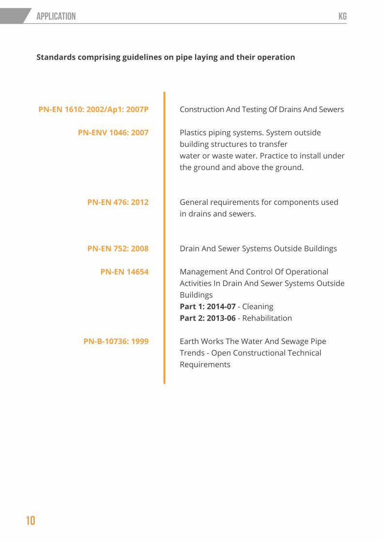
PN-EN 1610: 2002/Ap1: 2007P
PN-ENV 1046: 2007
PN-EN 476: 2012
PN-EN 752: 2008
PN-EN 14654
PN-B-10736: 1999
Construction And Testing Of Drains And Sewers
Plastics piping systems. System outside building structures to transferwater or waste water. Practice to install under the ground and above the ground.
General requirements for components used in drains and sewers.
Drain And Sewer Systems Outside Buildings
Management And Control Of Operational Activities In Drain And Sewer Systems Outside Buildings Part 1: 2014-07 - Cleaning Part 2: 2013-06 - Rehabilitation
Earth Works The Water And Sewage Pipe Trends - Open Constructional Technical Requirements
Standards comprising guidelines on pipe laying and their operation
10
Application KG

Product Catalogue KG

Table of content:
KGEM - socket pipes - co-extruded 13KGEL - socket pipes - solid wall 15KGB - bends 16KGEA - branches 17KGM - plugs 18KGK - end caps 18KGU - sleeves 19KG-ERMM - double sockets 19KGR - reducers 19KGUS - connectors with stoneware pipes 20KGUG - connectors with cast iron pipes 20KGRE - access pipes 20KGF - sleeve pipe for walls 21Seals 21
12
KG Product Catalogue KG

Pipes with socket - co-extruded (KGEM) EN 13476
Class A - SN2
DN d1 [mm]
s1 [mm]
D [mm]
t [mm]
L [mm]
Art.No.
160 160 3,2 183 110 500 22048160 160 3,2 183 110 1000 22050160 160 3,2 183 110 2000 22060160 160 3,2 183 110 3000 22063160 160 3,2 183 110 6000 22080
200 200 3,9 226 120 1000 23050200 200 3,9 226 120 2000 23060200 200 3,9 226 120 3000 23063200 200 3,9 226 120 6000 23080
Class B - SN4
DN d1 [mm]
s1 [mm]
D [mm]
t [mm]
L [mm]
Art.No.
110 110 3,2 128 76 500 20000110 110 3,2 128 76 1000 20010110 110 3,2 128 76 2000 20020110 110 3,2 128 76 3000 20023110 110 3,2 128 76 6000 20040
160 160 4,0 183 110 500 22000160 160 4,0 183 110 1000 22010160 160 4,0 183 110 2000 22020160 160 4,0 183 110 3000 22023160 160 4,0 183 110 6000 22040
200 200 4,9 226 120 500 23000200 200 4,9 226 120 1000 23010200 200 4,9 226 120 2000 23020200 200 4,9 226 120 3000 23023200 200 4,9 226 120 6000 23040
250 250 6,2 287 140 2000 24020250 250 6,2 287 140 3000 24023250 250 6,2 287 140 6000 24040
315 315 7,7 355 160 2000 25020315 315 7,7 355 160 3000 25023315 315 7,7 355 160 6000 25040
400 400 9,8 445 190 2000 26020400 400 9,8 445 190 3000 26023400 400 9,8 445 190 6000 26040
L
s
KG
13
KG Product Catalogue

Class C - SN8
DN d1 [mm]
s1 [mm]
D [mm]
t [mm]
L [mm]
Art.No.
110 110 3,2 128 76 500 20005110 110 3,2 128 76 1000 20015110 110 3,2 128 76 2000 20025110 110 3,2 128 76 3000 20028110 110 3,2 128 76 6000 20045
160 160 4,7 183 110 500 22005160 160 4,7 183 110 1000 22015160 160 4,7 183 110 2000 22025160 160 4,7 183 110 3000 22028160 160 4,7 183 110 6000 22045
200 200 5,9 226 120 1000 23015200 200 5,9 226 120 2000 23025200 200 5,9 226 120 3000 23028200 200 5,9 226 120 6000 23045
250 250 7,3 287 140 2000 24025250 250 7,3 287 140 3000 24028250 250 7,3 287 140 6000 24045
315 315 9,2 355 160 2000 25025315 315 9,2 355 160 3000 25028315 315 9,2 355 160 6000 25045
400 400 11,7 445 190 2000 26025400 400 11,7 445 190 3000 26028400 400 11,7 445 190 6000 26045
500 500 14,6 567 220 3000 27028500 500 14,6 567 220 6000 27045
L
s
14
KG Product Catalogue KG

Class C - SN8
DN d1 [mm]
s1 [mm]
D [mm]
t [mm]
L [mm]
Art.No.
110 110 3,2 128 76 1000 220015110 110 3,2 128 76 2000 220025110 110 3,2 128 76 3000 220028110 110 3,2 128 76 6000 220045
160 160 4,7 183 110 1000 222015160 160 4,7 183 110 2000 222025160 160 4,7 183 110 3000 222028160 160 4,7 183 110 6000 222045
200 200 5,9 226 120 1000 223015200 200 5,9 226 120 2000 223025200 200 5,9 226 120 3000 223028200 200 5,9 226 120 6000 223045
250 250 7,3 287 140 2000 224025250 250 7,3 287 140 3000 224028250 250 7,3 287 140 6000 224045
315 315 9,2 355 160 2000 225025315 315 9,2 355 160 3000 225028315 315 9,2 355 160 6000 225045
400 400 11,7 445 190 2000 226025400 400 11,7 445 190 3000 226028400 400 11,7 445 190 6000 226045
500 500 14,6 567 220 3000 227028500 500 14,6 567 220 6000 227045
Class B - SN4
DN d1 [mm]
s1 [mm]
D[mm]
t [mm]
L [mm]
Art.No.
160 160 4,0 183 110 1000 222010160 160 4,0 183 110 2000 222020160 160 4,0 183 110 3000 222023160 160 4,0 183 110 6000 22040
200 200 4,9 226 120 1000 223010200 200 4,9 226 120 2000 223020200 200 4,9 226 120 3000 223023200 200 4,9 226 120 6000 223040
250 250 6,2 287 140 3000 224023250 250 6,2 287 140 6000 224040
315 315 7,7 355 160 3000 225023315 315 7,7 355 160 6000 225040
Pipes with socket - solid wall (KGEL) EN 1401
L
s
KG
15
KG Product Catalogue
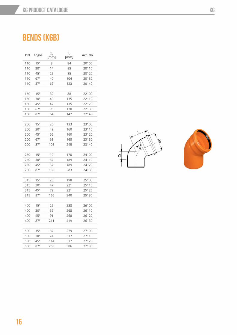
Bends (KGB)
DN angle z1 [mm]
L [mm] Art. No.
110 15° 8 84 20100110 30° 14 85 20110110 45° 29 85 20120110 67° 40 104 20130110 87° 69 123 20140
160 15° 32 88 22100160 30° 40 135 22110160 45° 47 135 22120160 67° 96 170 22130160 87° 64 142 22140
200 15° 26 133 23100200 30° 49 160 23110200 45° 65 160 23120200 67° 68 168 23130200 87° 105 245 23140
250 15° 19 170 24100250 30° 37 189 24110250 45° 57 189 24120250 87° 132 283 24130
315 15° 23 198 25100315 30° 47 221 25110315 45° 72 221 25120315 87° 166 340 25130
400 15° 29 238 26100400 30° 59 268 26110400 45° 91 268 26120400 87° 211 419 26130
500 15° 37 279 27100500 30° 74 317 27110500 45° 114 317 27120500 87° 263 506 27130
16
KG Product Catalogue KG
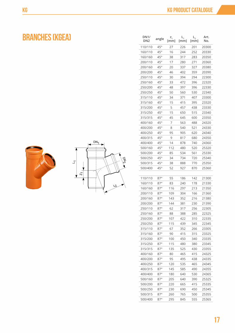
DN1/DN2 angle z1
[mm]L1
[mm]L2
[mm]Art. No.
110/110 45° 27 226 201 20300160/110 45° 16 244 252 20330160/160 45° 38 317 283 20350200/110 45° 17 280 271 20360200/160 45° 20 337 327 20380200/200 45° 46 402 359 20390250/110 45° 30 394 294 22300250/160 45° 33 472 396 22320250/200 45° 48 397 396 22330250/250 45° 50 560 530 22340315/110 45° 34 371 407 23300315/160 45° 15 415 395 23320315/200 45° 5 457 438 23330315/250 45° 15 650 515 23340315/315 45° 45 645 600 23350400/160 45° 7 563 488 24320400/200 45° 8 540 521 24330400/250 45° 95 905 620 24340400/315 45° 9 817 680 24350400/400 45° 14 878 740 24360500/160 45° 112 480 520 25320500/200 45° 85 534 561 25330500/250 45° 34 734 720 25340500/315 45° 38 888 770 25350500/400 45° 52 927 870 25360
110/110 87° 55 186 142 21300160/110 87° 83 240 178 21330160/160 87° 116 297 213 21350200/110 87° 109 304 166 21360200/160 87° 143 352 216 21380200/200 87° 144 381 230 21390250/110 87° 62 317 256 22305250/160 87° 88 388 285 22325250/200 87° 107 422 310 22335250/250 87° 115 439 345 22345315/110 87° 67 352 266 23305315/160 87° 90 415 315 23325315/200 87° 100 450 340 23335315/250 87° 115 480 380 23345315/315 87° 135 525 430 23355400/160 87° 80 465 415 24325400/200 87° 95 495 438 24335400/250 87° 120 535 465 24345400/315 87° 145 585 490 24355400/400 87° 180 640 530 24365500/160 87° 205 640 390 25325500/200 87° 220 665 415 25335500/250 87° 230 690 450 25345500/315 87° 260 765 500 25355500/400 87° 295 845 555 25365
Branches (KGEA)
KG
17
KG Product Catalogue

DN L[mm]
D [mm] Art. No.
110 32 120 20220160 42 170 22220200 50 217 23220250 80 265 24220315 80 333 25220400 80 423 26220500 80 525 27220
Plugs (KGM)
D
DN L [mm] Art. No.
110 43 20240160 52 22240200 64 23240250 68 24240315 77 25240400 90 26240
End caps (KGK)
L
DN L [mm] Art. No.
110 105 20180160 138 22180200 215 23180250 250 24180315 293 25180400 324 26180500 380 27180
Sleeves (KGU)
18
KG Product Catalogue KG

DN Z [mm]
L [mm] Art. No.
110 3 105 20200160 3 138 22200200 5 215 23200250 7 250 24200
DN1/DN2 L1 [mm]
L2 [mm] Art. No.
160/110 46 118 21280200/160 48 143 23280250/200 147 264 24280315/250 214 342 25280400/315 243 385 26280500/400 150 340 27280
Double sockets (KG-ERMM)
Reducers (KGR)
DN1/DN2 L1 [mm] L2 [mm] Art. No.
250/160 113 130 24283315/160 113 141 25283315/200 118 147 25284
Multi-stage reductions (KGR)
KG
19
KG Product Catalogue

DN D [mm] L [mm] Art. No.
110 138 151 20410160 194 207 22410200 250 248 23410
DN D [mm] L [mm] Art. No.
250* 315 283 24400315* 400 318 25400
Connectors with stoneware pipes (KGUS)
* for the connector with the stoneware pipes KGUS 250 and 315 KGUS seal has to be ordered separately
DN d1 [mm]
L[mm] Art. No.
110** 124 60 20440160** 187 98 22440200** 242 103 23440
Connectors for cast iron pipes (KGUG)
** to the connector with cast iron pipes KGUG DN 110-200 KGUG seal has to be ordered separately
d1
DN Z1 [mm]
L[mm] Art. No.
110 58 179 20160250 128 722 24160
Access pipes - locking plate (KGRE)
DDN
20
KG Product Catalogue KG
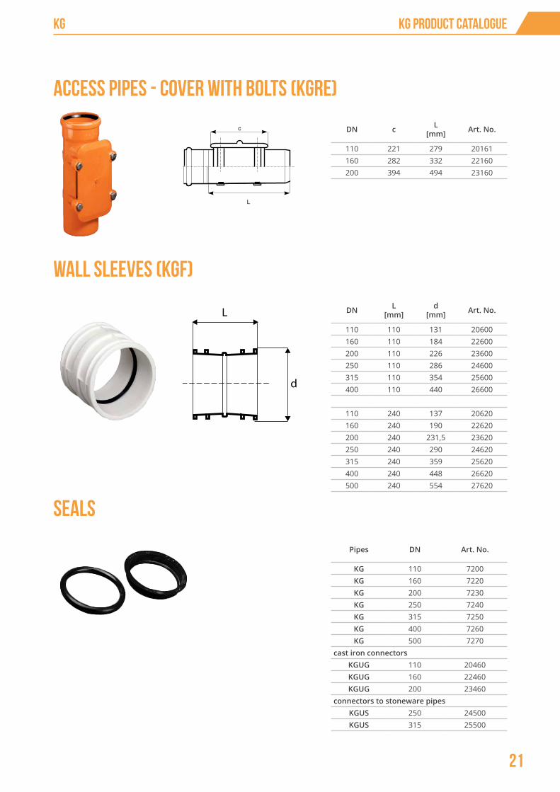
DN c L [mm] Art. No.
110 221 279 20161160 282 332 22160200 394 494 23160
Access pipes - cover with bolts (KGRE)
DN L [mm]
d [mm] Art. No.
110 110 131 20600160 110 184 22600200 110 226 23600250 110 286 24600315 110 354 25600400 110 440 26600
110 240 137 20620160 240 190 22620200 240 231,5 23620250 240 290 24620315 240 359 25620400 240 448 26620500 240 554 27620
Pipes DN Art. No.
KG 110 7200KG 160 7220KG 200 7230KG 250 7240KG 315 7250KG 400 7260KG 500 7270
cast iron connectorsKGUG 110 20460KGUG 160 22460KGUG 200 23460
connectors to stoneware pipesKGUS 250 24500KGUS 315 25500
Wall sleeves (KGF)
Seals
d
L
KG
21
KG Product Catalogue

Hydraulic dimensioning of PVC-U sewage pipes
The hydraulic calculations for sewage pipe sections will involve determination of their diameters, heights of wastewater filling and flow rates. The calculations are made on the basis of computational flow rate and assumed pipe bottom inclination absolute roughness of pipe walls under the assumption that:
• size,• pipe shape, its inclination,• roughness and assumed computational flow at the overall computational length of
the pipe remain constant,• flow rates are identical at all points of flux section.
The hydraulic calculations for sewage pipe sections will involve determination of their diameters, heights of wastewater filling and flow rates. The calculations are made on the basis of computational flow rate and assumed pipe bottom inclination absolute roughness of pipe walls under the assumption that:
22
Design KG

Inclination I [‰]
Inclination I [‰]
Flow
rat
e [
dm3 /
s]
Fig. 2. Nomogram for hydraulic calculations with sewage pipe full filled.
KG
23
Design

The basic parameter for selection of sewage pipe inclination is safeguarding self-cleaning conditions i.e. to obtain in the sewage pipes the lowest flow rate that prevents sedimentation process at pipe bottom. Flow rates meeting the requirement of self-cleaning when the pipe is completely filled should not be smaller than:
V = 0.8 m/s - for sanitary sewage system,V = 0.6 m/s - for stormwater drainage system,V = 1.0 m/s - for combined sewage system.
The flow rates should not be treated at constant, but dependent on the pipe diameter and should grow together with the diameter. To comply with the above requirement, the minimum inclinations of pipes can be assumed as Imin =1/d, where d is an internal diameter [mm].
Fig. 3.
Efficiency curve Q and V
24
Design KG

Tab. 3. Minimum inclinations I [‰] of PVC-U sewage pipes
Diameter DN [mm]
sanitary sewerage systemVmin = 0.8 [m/s]
stormwater drainage systemV min= 0.6 [m/s]
combined sewage systemV= 1.0 [m/s]
inclination l [‰ ]
k = 0,4 k = 0,25 k = 0,4 k = 0,25 k = 0,4 k = 0,25
160 6,0 4,5 3,4 2,7 9,5 6,5
200 3,4 3,5 2,5 2,0 7,0 5,2
250 3,4 2,6 1,8 1,5 5,2 4,0
315 2,5 2,0 1,4 1,2 4,0 3,0
400 2,0 1,5 1,0 0,85 3,0 2,3
When designing sewage system, owing to a need of appropriate venting of pipes, the rule should be followed that even with maximum flows the pipe should not be completely filled.
Diameter DN [mm]
Maximum inclination I [%] at maximum flow rate
Sanitary sewage system Vmax = 5.0 [m/s] Stormwater drainage system and combined sewage system Vmax = 7.0 [m/s]
200 23,0 45,1
250 16,8 32,9
315 13,3 28,0
400 9,0 17,7
500 6,8 13,3
Tab. 4. Approximate values of maximum inclinations of sewage pipes under the assumption of maximum flow rates.
DN [mm] d* [mm] hn/d hn [cm]
110 104,0 0,6 6,0
125 119,0 0,6 7,2
160 152,8 0,6 9,0
200 191,0 0,6 11,0
250 237,8 0,6 14,0
315 299,6 0,6 18,0
400 380,4 0,7 26,0
500 475,6 0,7 35,0
(*) - inside diameter of SN4 class pipe (SDR 41)
Tab. 5. Recommended filling hn of circular sewage pipes with internal diameter d at Qmax
KG
25
Design

For instance:
For a certain flow rate of wastewater Q1 =40dm3/s and inclination of pipe bottom i =2‰ using nomogram one has to select pipe diameter under the assumption of complete filling DN200mm and then numerical value for such flow has to be read out QV =53 dm3/s along with flow rate VV =1.8 m/s. Then Q1 to QV ratio should be calculated: 40/53=0.75 using the efficiency curve Q (Fig. 3) then filling H/DN =0.65 has to be read out, thus filling H1 =0.65 x 20=13 cm. For a certain filling to diameter ratio the value of V1 to VV ratio equal to 1,16 has to be read on the efficiency curve V, and velocity has to be calculated for the flow Q1 =40 dm3 /s. V1 =1,8 x 1.16=2.0 m/s.
26
Design KG

SOLUTIONS FOR YEARS

HTplus indoor sewage system
Ultra B low-noise indoor sewage system
Skolan- B thick-walled, low-noise sewage system
KG PVC outdoor sewerage system
PP outdoor sewerage system Magnacor
Sewerage chambers system
Polyethylene (PE) pressure pipes
Drainage (DR) systems
sieniawa żarska 69, 68-213 lipinki łużyckiePOLAND
tel.: +48 68 363 27 00fax: +48 68 363 27 72