casting - tyco-fire.com · casting central produces ductile iron, astm a-536, grade 65-45-12 for...
TRANSCRIPT


CASTING
Central produces ductile iron, ASTM A-536,Grade 65-45-12 for all of its grooved products.Once the base iron is produced, magnesium is addedin precise measurements to develop the ductile irongrade. The metal is tested chemically, physically, andmicroscopically prior to being released for production.Once cast, the ductile iron is once again checked toensure conformance with these specifications.
Central Grooved Piping Products has alwaysunderstood the complexity of providing gasketscapable of exceeding customer demands. With stateof the art rubber injection presses and tooling, we areable to mold several types of rubber compounds to meet the various needs of the market. Ourgaskets are 100% manufactured by ourselves in our facility in Alabama. Each gasket is 100%inspected to ensure it is defect free. Physical tests are performed on the gaskets to verify compliance withspecifications such as ASTM D-2000. Central’s quality program is superior to that of the competition in thatwe test actual molded gaskets as compared to testing of slabs. Slab testing does not reflect the actualproperties of the molded part as the slab is constructed under laboratory conditions. In addition, all gasketsare injection molded in all sizes up through 24" as a complete gasket. Other manufacturers do not
manufacture all of their products, and supply gaskets from vendors orsupply gaskets which are extruded and then spliced together with glue.
RUBBER INJECTION
Central products are designed utilizing the finest engineeringtalent and innovative practices available. Central's engineeringdepartment provides product designs to Central's patterncenters as well as contracted pattern makers. The patternsand molding machines are capable of providing the closesttolerance parts available using the green sand method ofcasting. We have the ability to construct, maintain and modifypatterns to meet the demands of the market place.
A computer controlled semi-automatic process paintsour Grooved Products. The process ensures that the productsare spray washed, dried, pre-heated, dipped and fully cured priorto being assembled or packaged for shipment.All painted parts are quality controlled to maintain consistentpaint coverage and surface condition.
TOOLING
THE PAINT PROCESS
CASTING
Central produces ductile iron, ASTM A-536,Grade 65-45-12 for all of its Central Grooved Pipingproducts. Once the base iron is produced, magnesium isadded in precise measurements to develop the ductile irongrade. The metal is tested chemically, physically, andmicroscopically prior to being released for production.Once cast, the ductile iron is once again checked toconfirm conformance with these specifications.
Central Grooved Piping Products understands thecomplexity of providing gaskets capable of exceedingcustomer demands. With state of the art rubberinjection presses and tooling, we are able to moldseveral types of rubber compounds to meet the various needs of the market. We manufacture100% of our gaskets in our facility in Alabama, each inspected to zero defects. Physical testsare performed on each gasket to verify compliance with specifications such as ASTM D-2000. CentralGrooved Piping Product’s quality program surpasses the competition by testing actual molded gaskets ascompared to testing of raw slabs. Slab testing does not reflect the actual properties of the molded part asthe slab is constructed under laboratory conditions. In addition, all gaskets are injection molded in all sizesup through 24" as a complete gasket.
RUBBER INJECTION
Tyco Fire Products are designed utilizing the finest engineeringtalent and innovative practices available. Our engineeringdepartment provides product designs to our pattern centers.The patterns and molding machines are capable of the closesttolerance parts available using the green sand method ofcasting. We have the ability to construct, maintain and modifypatterns to meet the demands of the market place.
Central Grooved Piping Products utilizes a computer controlledsemi-automatic process to paint our Grooved Products. Theprocess ensures that the products are spray washed, dried, pre-heated, dipped and fully cured prior to being assembled orpackaged for shipment. All painted parts are quality controlled tomaintain consistent paint coverage and surface condition.
TOOLING
THE PAINT PROCESS

INDUSTRY LEADERSHIP THROUGH
INNOVATION AND ENGINEERING EXCELLENCE
Tyco Fire Products and Central Grooved Piping Products are ISO 9001 Certified
with products manufactured in our newly constructed domestic ductile iron foundry
and manufacturing facilities. We are committed to maintaining our leadership role in
the grooved piping industry through aggressive research and development. The
products that will improve our industry tomorrow are being designed today. With this
level of investment and commitment, Tyco Fire Products is
quickly becoming the industry standard.
Tyco Fire Products is a world leader in the manufacture
and distribution of piping products. Years of development,
engineering, pattern and tooling making, and the
acquisition of the necessary resources have provided the
finest grooved products available on the market today.
Grooved Piping Products are domestically manufactured to
the highest quality standards as set forth by independent
testing laboratories.
Our grooved product line utilizes industry leading manufacturing technology. Our
Disamatic molding centers have the ability to cast ductile iron products to extremely
tight tolerances. Computer controlled data systems in the foundry provide
confidence that all equipment and processes are operating within
specified guidelines. Rubber gaskets and components are injection
molded at our facility using innovative processes to comply with
exacting tolerances and specifications.
Tyco Fire Products takes pride in its total quality management
approach as demonstrated by our ISO 9001 Certification. Quality
management is defined in terms of performance, features,
dependability, conformance, and durability.
The Quality process starts in the design phase. Performance and
durability are designed into each product. Our modern manufacturing facilities
conform to rigid engineering specifications.
Tyco Fire Products Engineering Facility, directs product development from the
concept through design, testing and manufacturing. Our engineering & technical
services group establishes all parameters of application engineering and quality
assurance. Owners, architects, consulting engineers, contractors and tenants
demand the most dependable, quality grooved products for their piping systems— our
engineering staff ensures their demands are met each and every time.

4
TABLE OF CONTENTS
Table of Contents
Introduction ................................................ 5 - 7ISO 9001 Approval ................................................. 5
Grooved Couplings ................................................ 6
General Data ......................................................... 7
Grooved Couplings................................... 8 - 13Figure 572 Rigid Coupling ..................................... 8
Figure 772 Rigid Coupling ..................................... 9
Figure 575 Flexible Coupling ............................... 10
Figure 705 Flexible Coupling ............................... 11
Figure 707 Heavy Duty Flexible Coupling ........... 12
Figure 716 Reducing Coupling ............................ 13
Mechanical Outlets ................................. 14 - 15Figure 730 (Threaded) ......................................... 14
Figure 730 (Grooved) .......................................... 15
Figure 40-5........................................................... 16
Flange AdapterFigure 71 .............................................................. 17
Grooved Fittings ..................................... 18 - 23Figure 201/501 45° Elbow ................................... 18
Figure 210/510 90° Elbow ................................... 18
Figure 219/519 Tee .............................................. 18
Figure 260 End Cap ............................................. 19
Figure 312 221⁄2° Elbow ....................................... 19
Figure 313 111⁄4° Elbow ........................................ 19
Figure 327 Cross ................................................. 19
Figure 315 90° Elbow (Gr. x Thd.) ....................... 20
Figure 320 Tee (Gr. x Thd.) .................................. 20
Figure 510DE 90° Drain Elbow............................ 20
Figure 341 150 lb. Flange Adapter ...................... 20
Figure 321 Reducing Tee (Gr. x Gr.) .................... 21
Figure 323 Reducing Tee (Gr. x Thd.) ................ 21
Figure 301 Adapter Nipple (Gr. x Thd.) .............. 22
Figure 302 Adapter Nipple (Gr. x Gr.) ................. 22
Figure 303 Adapter Nipple (Gr. x Bev.) ............... 22
Figure 350 Concentric Reducer (Gr. x Gr.) .......... 22
Figure 372 Concentric Reducer (Gr. x Thd.) ....... 22
Ada-Cap® ............................................................. 23
Valves ....................................................... 24 - 27Butterfly Valve
Figure 570 ...................................................... 24
Figure 580 ...................................................... 24
Check Valves
Figure 590F .................................................... 25
Maintenance Kit ............................................. 26
Figure 590FR ................................................. 27
Riser Manifold
Figure 513, 513D/513R .......................... 28 - 31
Gaskets ........................................................... 32
Roll Groove Specifications ........................... 33
Terms and Conditions ................................... 34Ordering Procedure ............................................. 34
Care and Maintenance ........................................ 34
Limited Warranty .................................................. 34
Grooved PipingProducts
Refer to our Grooved PipingProducts Handbook for detailed
installation instructions
5
GROOVED PIPING PRODUCTS –––––––– ISO 9001 APPROVAL
Factory Mutual Research Corporation
CERTIFICATE OF REGISTRATION
FMRC certifies herewith that
TYCO FIRE PRODUCTS1550 Valley Center Parkway, Suite 135
Bethlehem, PA 18017
has demonstrated a Quality Assurance System
that complies with the requirements of
This registration is subject to ongoing audits by FMRC.Any change to the basis of this registration requires
acceptance in writing by FMRC.
Date
June 10, 1999
ISO 9001
Scope:
Registration No.
990604.1 June 30, 2002
Expiration Date
DESIGN AND MANUFACTURE OF CASTINGS, PIPE COUPLINGS, FITTINGS, VALVES, AND
RELATED PIPING SYSTEM PRODUCTS
RvAThe Dutch Council for Accreditation
FMRC
QU
A
LITY SYSTEM
RE
GISTRATIO
N
®
John Rennie, Vice President
Introduction
6 Introduction
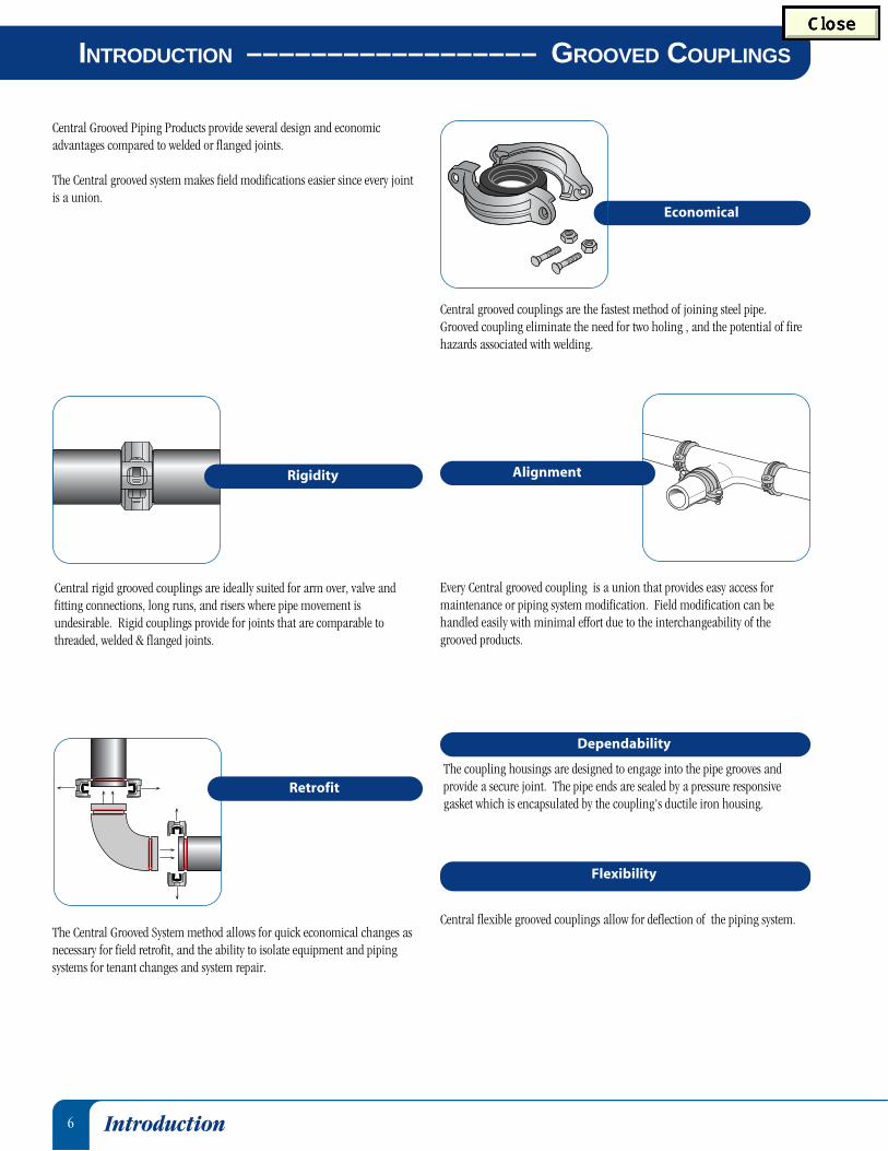
Central Grooved Piping Products provide several design and economicadvantages compared to welded or flanged joints.
The Central grooved system makes field modifications easier since every jointis a union.
Economical
Central rigid grooved couplings are ideally suited for arm over, valve andfitting connections, long runs, and risers where pipe movement isundesirable. Rigid couplings provide for joints that are comparable tothreaded, welded & flanged joints.
The Central Grooved System method allows for quick economical changes asnecessary for field retrofit, and the ability to isolate equipment and pipingsystems for tenant changes and system repair.
Central flexible grooved couplings allow for deflection of the piping system.
The coupling housings are designed to engage into the pipe grooves andprovide a secure joint. The pipe ends are sealed by a pressure responsivegasket which is encapsulated by the coupling's ductile iron housing.
Every Central grooved coupling is a union that provides easy access formaintenance or piping system modification. Field modification can behandled easily with minimal effort due to the interchangeability of thegrooved products.
INTRODUCTION –––––––––––––––––– GROOVED COUPLINGS
Rigidity
Retrofit
Alignment
Dependability
Flexibility
Central grooved couplings are the fastest method of joining steel pipe.Grooved coupling eliminate the need for two holing , and the potential of firehazards associated with welding.
7
Coast Guard - Approved each vessel individuallyCorps of Engineers (COE) - GEGS 15000Federal Aviation Administration (FAA)
HVAC, Plumbing and Fire ProtectionFederal Housing Administration (FHA)General Services Administration (GSA) - 15000 SeriesMilitary Specifications (MIL)
MIL P - 10388 Fittings;MIL - C - 10387 Couplings;MIL - P - 11087A (CE) Steel Pipe,Grooved MIL - I - 45208 Inspection Procedure
National Aeronautics and Space Administration (NASA)Naval Facilities Engineering Command (NAVFAC) -
NFGS 15000 SeriesNational Institute of Health (NIH) - Dept. of Health - 15000 SeriesVeterans Affairs (VA) - 15000 Series
American Bureau of Shipping (ABS)American National Standards Institute / American Water Works
Association (ANSI / AWWA)American Petroleum Institute (API) - API Std. 5L, Sect. 7.5American Society of Heating, Refrigerating and
Air Conditioning Engineers (ASHRAE)American Society of Mechanical Engineers (ASME)
Power Piping, B-31.1; Chemical Plant and Petroleum Refinery Piping,B-31.3; Refrigeration Piping, B-31.5; Building Services Piping, B-31.9.
Building Officials and Code Administrators (BOCA)Factory Mutual Enginering Corp. (FM) - Approved for Fire Protection
ServicesMaterial Equipment and Acceptance (MEA)National Fire Protection Association (NFPA)New York Board of Standards and Appeals (NY-BSA)Southern Building Code Congress International (SBCCI) -
Standard PlumbingUnderwriter’s Laboratories, Inc. (UL) - Listed for Fire
Protection ServicesUnderwriters Laboratories of Canada (ULC) — Listed for Fire
Protection Services
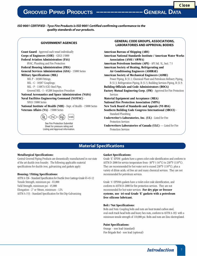
Metallurgical Specifications:Central Grooved Piping Products are domestically manufactured in our stateof the art ductile iron foundry. The following applicable materialspecifications for ductile iron, galvanizing and gaskets apply:
Housing / Fitting Specifications:ASTM A-536 - Standard Specification for Ductile Iron Castings Grade 65-45-12Tensile Strength, minimum psi - 65,000Yield Strength, minimum psi - 45,000Elongation - 2" or 50mm, minimum - 12%ASTM A-153 - Standard Specification for Hot Dip Galvanizing
Gasket Specifications:Grade ‘E’ EPDM gaskets have a green color code identification and conform toASTM D-2000 for service temperature from -30°F (-34°C) to 230°F (110°C).They are recommended for hot water not to exceed 230°F (110°C), plus avariety of dilute acids, oil free air and many chemical services. They are notrecommended for petroleum services.
Grade ‘A’ EPDMA gaskets have a violet color code identification, andconform to ASTM D-2000 for fire protection services. They are notrecommended for hot water services. For dry pipe or freezersystems, use tri-seal Grade ‘E’ gaskets with a petroleumfree silicone lubricant.
Bolt / Nut Specifications:Bolts and Nuts: Coupling bolts and nuts are heat treated carbon steel,oval-neck track head bolts and heavy hex nuts, conform to ASTM A-183 with aminimum tensile strength of 110,000 psi. Bolts and nuts are Zinc electroplated.
Paint Specifications:Orange - non lead (standard)Fire Brigade Red - non lead (optional)
GOVERNMENT AGENCIES GENERAL CODE GROUPS, ASSOCIATIONS,LABORATORIES AND APPROVAL BODIES
Material Specifications
ISO 9001 CERTIFIED - Tyco Fire Products is ISO 9001 Certified confirming conformance to thequality standards of our products.
GROOVED PIPING PRODUCTS –––––––––––––GENERAL DATA
Introduction
FM
See Fire Protection Submittal Sheet for pressure rating and
Listing and Approval information.

8
FIGURE 572 ––––––––––––––––––––––– RIGID COUPLING
* Maximum available gap between pipe ends. Minimum gap = 0.† Maximum pressure and end load are total from all loads based on standard weight steel pipe. Pressure ratings and end loads may differ on other pipe materials and/or wallthickness. Contact Tyco Fire Products for details.General Notes: This catalog is general in nature and does not include details on assembly instructions. Additional information is included in our data sheets and
is available upon request. It is the Designer’s responsibility to select products suitable for the intended service and to ensure that pressure ratingsand performance data is not exceeded. Systems should always be depressurized and drained before removing any piping component. Material andgasket selections should be verified to be compatible for the specific application. See Fire Protection Equipment Submittal Sheet for Listing andApproval pressure ratings.
CB
A
Figure 572 Rigid Couplings are capable ofpressures up to 300 psi and provide a rigid joint byfirmly gripping the pipe grooves. Rigid Couplingsare preferred for dry pipe and freezer applications.Figure 572 Rigid Couplings are a provendependable method of joining pipe and are aneconomical alternative to welding, threading, orflanges, and can be used on a variety of pipe andwall thicknesses. The Figure 572 Coupling has an
Anti-Rotation Feature of “gripping teeth” alongthe coupling keys that make the Figure 572perfectly suited for “arm over” installations wherethe likelihood of rotation is greatest. This featuremay eliminate the need of extra hangers to supportthe arm over, saving time and cost.
Figure 572 - Rigid CouplingPipe Max. * Max.† Max.† Dimensions Bolt Net
O.D. End Gap Pressure End Load A B C Size Wt.Size Inches Inches psi Lbs. Inches Inches Inches Dia. x Lg. Lbs.
mm mm kPa N mm mm mm Kg.
11⁄4" 1.660 0.06 300 650 2.56 4.09 1.69 3⁄8" x 21⁄4" 0.942.2 1.5 2,068 2,891 65.0 103.9 42.9 0.4
11⁄2" 1.900 0.06 300 850 2.81 4.38 1.81 3⁄8" x 21⁄4" 1.048.3 1.5 2,068 3,783 71.4 111.3 46.0 0.5
2" 2.375 0.06 300 1,329 3.31 4.82 1.88 3⁄8" x 21⁄4" 1.260.3 1.5 2,068 5,914 84.1 122.4 47.8 0.5
21⁄2" 2.875 0.06 300 1,948 3.81 5.38 1.88 3⁄8" x 21⁄4" 1.373.0 1.5 2,068 8,668 96.8 136.7 47.8 0.6
3" 3.500 0.06 300 2,886 4.50 6.06 1.88 3⁄8" x 21⁄4" 1.788.9 1.5 2,068 12,843 114.3 153.9 47.8 0.8
4" 4.500 0.19 300 4,771 5.69 7.38 1.88 3⁄8" x 21⁄4" 2.7114.3 4.8 2,068 21,231 144.5 187.5 47.8 1.2
6" 6.625 0.19 300 10,341 7.94 9.88 1.88 1⁄2" x 3" 5.3168.3 4.8 2,068 46,018 201.7 251.0 47.8 2.4
8" 8.625 0.19 300 17,528 10.13 12.69 2.25 5⁄8" x 3" 7.2219.1 4.8 2,068 78,000 257.3 322.3 57.2 3.3
FM
See Fire Protection Submittal Sheet for pressure rating and
Listing and Approval information.
Patented
Grooved Couplings
9
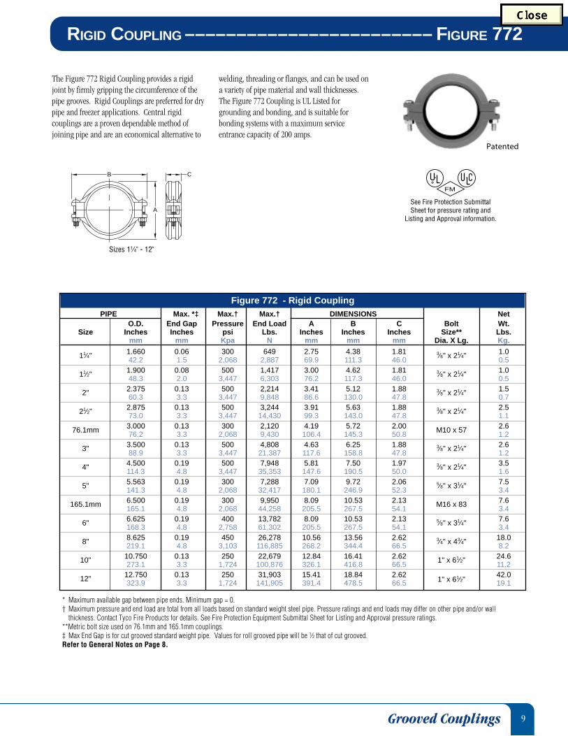
The Figure 772 Rigid Coupling provides a rigidjoint by firmly gripping the circumference of thepipe grooves. Rigid Couplings are preferred for drypipe and freezer applications. Central rigidcouplings are a proven dependable method ofjoining pipe and are an economical alternative to
Patented
RIGID COUPLING –––––––––––––––––––––––– FIGURE 772
FM
See Fire Protection Submittal Sheet for pressure rating and
Listing and Approval information.
welding, threading or flanges, and can be used ona variety of pipe material and wall thicknesses.The Figure 772 Coupling is UL Listed forgrounding and bonding, and is suitable forbonding systems with a maximum serviceentrance capacity of 200 amps.
* Maximum available gap between pipe ends. Minimum gap = 0.† Maximum pressure and end load are total from all loads based on standard weight steel pipe. Pressure ratings and end loads may differ on other pipe and/or wall
thickness. Contact Tyco Fire Products for details. See Fire Protection Equipment Submittal Sheet for Listing and Approval pressure ratings.**Metric bolt size used on 76.1mm and 165.1mm couplings.‡ Max End Gap is for cut grooved standard weight pipe. Values for roll grooved pipe will be 1⁄2 that of cut grooved.Refer to General Notes on Page 8.
Sizes 11⁄4" - 12"
CB
A
Figure 772 - Rigid CouplingPIPE Max. *‡ Max.† Max.† DIMENSIONS Net
O.D. End Gap Pressure End Load A B C Bolt Wt.Size Inches Inches psi Lbs. Inches Inches Inches Size** Lbs.
mm mm Kpa N mm mm mm Dia. X Lg. Kg.
11⁄4" 1.660 0.06 300 649 2.75 4.38 1.81 3⁄8" x 21⁄4" 1.042.2 1.5 2,068 2,887 69.9 111.3 46.0 0.5
11⁄2" 1.900 0.08 500 1,417 3.00 4.62 1.81 3⁄8" x 21⁄4" 1.048.3 2.0 3,447 6,303 76.2 117.3 46.0 0.5
2" 2.375 0.13 500 2,214 3.41 5.12 1.88 3⁄8" x 21⁄4" 1.560.3 3.3 3,447 9,848 86.6 130.0 47.8 0.7
21⁄2" 2.875 0.13 500 3,244 3.91 5.63 1.88 3⁄8" x 21⁄4" 2.573.0 3.3 3,447 14,430 99.3 143.0 47.8 1.1
76.1mm 3.000 0.13 300 2,120 4.19 5.72 2.00 M10 x 57 2.676.2 3.3 2,068 9,430 106.4 145.3 50.8 1.2
3" 3.500 0.13 500 4,808 4.63 6.25 1.88 3⁄8" x 21⁄4" 2.688.9 3.3 3,447 21,387 117.6 158.8 47.8 1.2
4" 4.500 0.19 500 7,948 5.81 7.50 1.97 3⁄8" x 21⁄4" 3.5114.3 4.8 3,447 35,353 147.6 190.5 50.0 1.6
5" 5.563 0.19 300 7,288 7.09 9.72 2.06 5⁄8" x 31⁄4" 7.5141.3 4.8 2,068 32,417 180.1 246.9 52.3 3.4
165.1mm 6.500 0.19 300 9,950 8.09 10.53 2.13 M16 x 83 7.6165.1 4.8 2,068 44,258 205.5 267.5 54.1 3.4
6" 6.625 0.19 400 13,782 8.09 10.53 2.13 5⁄8" x 31⁄4" 7.6168.3 4.8 2,758 61,302 205.5 267.5 54.1 3.4
8" 8.625 0.19 450 26,278 10.56 13.56 2.62 3⁄4" x 43⁄4" 18.0219.1 4.8 3,103 116,885 268.2 344.4 66.5 8.2
10" 10.750 0.13 250 22,679 12.84 16.41 2.62 1" x 61⁄2" 24.6273.1 3.3 1,724 100,876 326.1 416.8 66.5 11.2
12" 12.750 0.13 250 31,903 15.41 18.84 2.621" x 61⁄2"
42.0323.9 3.3 1,724 141,905 391.4 478.5 66.5 19.1
Grooved Couplings
10
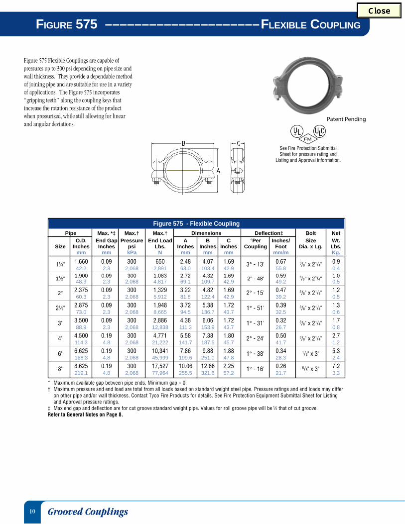
FIGURE 575 –––––––––––––––––––––FLEXIBLE COUPLING
Figure 575 Flexible Couplings are capable ofpressures up to 300 psi depending on pipe size andwall thickness. They provide a dependable methodof joining pipe and are suitable for use in a varietyof applications. The Figure 575 incorporates“gripping teeth” along the coupling keys thatincrease the rotation resistance of the productwhen pressurized, while still allowing for linearand angular deviations.
* Maximum available gap between pipe ends. Minimum gap = 0.† Maximum pressure and end load are total from all loads based on standard weight steel pipe. Pressure ratings and end loads may differ
on other pipe and/or wall thickness. Contact Tyco Fire Products for details. See Fire Protection Equipment Submittal Sheet for Listingand Approval pressure ratings.
‡ Max end gap and deflection are for cut groove standard weight pipe. Values for roll groove pipe will be 1⁄2 that of cut groove.Refer to General Notes on Page 8.
FM
See Fire Protection Submittal Sheet for pressure rating and
Listing and Approval information.
Figure 575 - Flexible CouplingPipe Max. *‡ Max.† Max.† Dimensions Deflection‡ Bolt Net
O.D. End Gap Pressure End Load A B C °Per Inches/ Size Wt.Size Inches Inches psi Lbs. Inches Inches Inches Coupling Foot Dia. x Lg. Lbs.
mm mm kPa N mm mm mm mm/m Kg.
11⁄4" 1.660 0.09 300 650 2.48 4.07 1.69 3° - 13' 0.67 3/8" x 21/4" 0.942.2 2.3 2,068 2,891 63.0 103.4 42.9 55.8 0.4
11⁄2" 1.900 0.09 300 1,083 2.72 4.32 1.69 2° - 48' 0.59 3/8" x 21/4" 1.048.3 2.3 2,068 4,817 69.1 109.7 42.9 49.2 0.5
2" 2.375 0.09 300 1,329 3.22 4.82 1.69 2° - 15' 0.47 3/8" x 21/4" 1.260.3 2.3 2,068 5,912 81.8 122.4 42.9 39.2 0.5
21⁄2" 2.875 0.09 300 1,948 3.72 5.38 1.72 1° - 51' 0.39 3/8" x 21/4" 1.373.0 2.3 2,068 8,665 94.5 136.7 43.7 32.5 0.6
3" 3.500 0.09 300 2,886 4.38 6.06 1.72 1° - 31' 0.32 3/8" x 21/4" 1.788.9 2.3 2,068 12,838 111.3 153.9 43.7 26.7 0.8
4" 4.500 0.19 300 4,771 5.58 7.38 1.80 2° - 24' 0.50 3/8" x 21/4" 2.7114.3 4.8 2,068 21,222 141.7 187.5 45.7 41.7 1.2
6" 6.625 0.19 300 10,341 7.86 9.88 1.88 1° - 38' 0.34 1/2" x 3" 5.3168.3 4.8 2,068 45,999 199.6 251.0 47.8 28.3 2.4
8" 8.625 0.19 300 17,527 10.06 12.66 2.25 1° - 16' 0.26 5/8" x 3" 7.2219.1 4.8 2,068 77,964 255.5 321.6 57.2 21.7 3.3
Patent Pending
Grooved Couplings

11
* Maximum available gap between pipe ends. Minimum gap = 0.† Maximum pressure and end load are total from all loads based on standard weight steel pipe. Pressure ratings and end loads may differ on other pipe and/or wall thickness.
Contact Tyco Fire Products for details. See Fire Protection Equipment Submittal Sheet for Listing and Approval pressure ratings.**Metric bolt size used on 76.1mm and 165.1mm couplings.‡ Max End Gap and Deflection are for cut grooved standard weight pipe. Values for roll grooved pipe will be 1⁄2 that of cut grooved.Refer to General Notes on Page 8.
The Figure 705 Flexible Coupling is capable ofpressures up to 300 psig depending on pipe sizeand wall thickness. It provides a dependablemethod of joining pipe and is suitable for use in avariety of applications.
FLEXIBLE COUPLING ––––––––––––––––––––– FIGURE 705
FM
See Fire Protection Submittal Sheet for pressure rating and
Listing and Approval information.
Figure 705 - Flexible CouplingPIPE Max. *‡ Max.† Max.† DIMENSIONS DEFLECTION ‡ Bolt Net
O.D. End Gap Pressure End Load A B C Degrees Size** Wt.Size Inches Inches psi Lbs. Inches Inches Inches Per In/Ft Dia. X Lg. Lbs.
mm mm Kpa N mm mm mm Coupling mm⁄m Kg.
11⁄4" 1.660 0.13 300 649 2.53 4.19 1.81 4° - 19' 0.90 3⁄8" x 21⁄4" 1.542.2 3.3 2,068 2,887 64.3 106.4 46.0 75.0 0.7
11⁄2" 1.900 0.13 300 850 2.75 4.43 1.81 3° - 46' 0.79 3⁄8" x 21⁄4" 1.648.3 3.3 2,068 3,781 69.9 112.5 46.0 65.8 0.7
2" 2.375 0.13 300 1,328 3.25 4.84 1.88 3° - 1' 0.63 3⁄8" x 21⁄4" 1.760.3 3.3 2,068 5,907 82.6 122.9 47.8 52.5 0.8
21⁄2" 2.875 0.13 300 1,947 3.69 5.50 1.88 2° - 29' 0.52 3⁄8" x 21⁄4"2.0
73.0 3.3 2,068 8,660 93.7 139.7 47.8 43.3 0.9
76.1mm 3.000 0.13 300 2,120 3.97 5.75 1.88 2° - 23' 0.50 M12 x 76 3.176.2 3.3 2,068 9,430 100.8 146.1 47.8 41.7 1.4
3" 3.500 0.13 300 2,885 4.38 6.50 1.88 2° - 3' 0.43 1⁄2" x 3" 3.088.9 3.3 2,068 12,832 111.3 165.1 47.8 35.8 1.4
4" 4.500 0.25 300 4,769 5.68 7.75 2.06 3° - 11' 0.67 1⁄2" x 3" 4.0114.3 6.4 2,068 21,213 144.3 196.9 52.3 55.8 1.8
5"5.563 0.25 300 7,288 6.88 9.72 2.06 2° - 35' 0.54 5⁄8" x 31⁄4" 7.0141.3 6.4 2,068 32,417 174.8 246.9 52.3 45.0 3.2
165.1mm 6.500 0.25 300 9,950 7.75 10.68 2.06 2° - 12' 0.46 M16 x 83 7.1165.1 6.4 2,068 44,258 196.9 271.3 52.3 38.3 3.2
6" 6.625 0.25 300 10,336 7.91 10.68 2.06 2° - 10' 0.45 5⁄8" x 31⁄4" 7.1168.3 6.4 2,068 45,975 200.9 271.3 52.3 37.5 3.2
8" 8.625 0.25 300 17,519 10.19 13.56 2.47 1° - 40' 0.35 3⁄4" x 43⁄4" 14.5219.1 6.4 2,068 77,925 258.8 344.4 62.7 29.2 6.6
10"10.750 0.25 250 22,679 12.69 16.38 2.63 1° - 20' 0.28 1" x 61⁄2" 28.0273.1 6.4 1,724 100,876 322.3 416.1 66.8 23.3 12.7
12"12.750 0.25 250 31,903 14.91 18.84 2.63 1° - 7' 0.23 1" x 61⁄2" 36.5323.9 6.4 1,724 141,905 378.7 478.5 66.8 19.2 16.6
Grooved Couplings
12
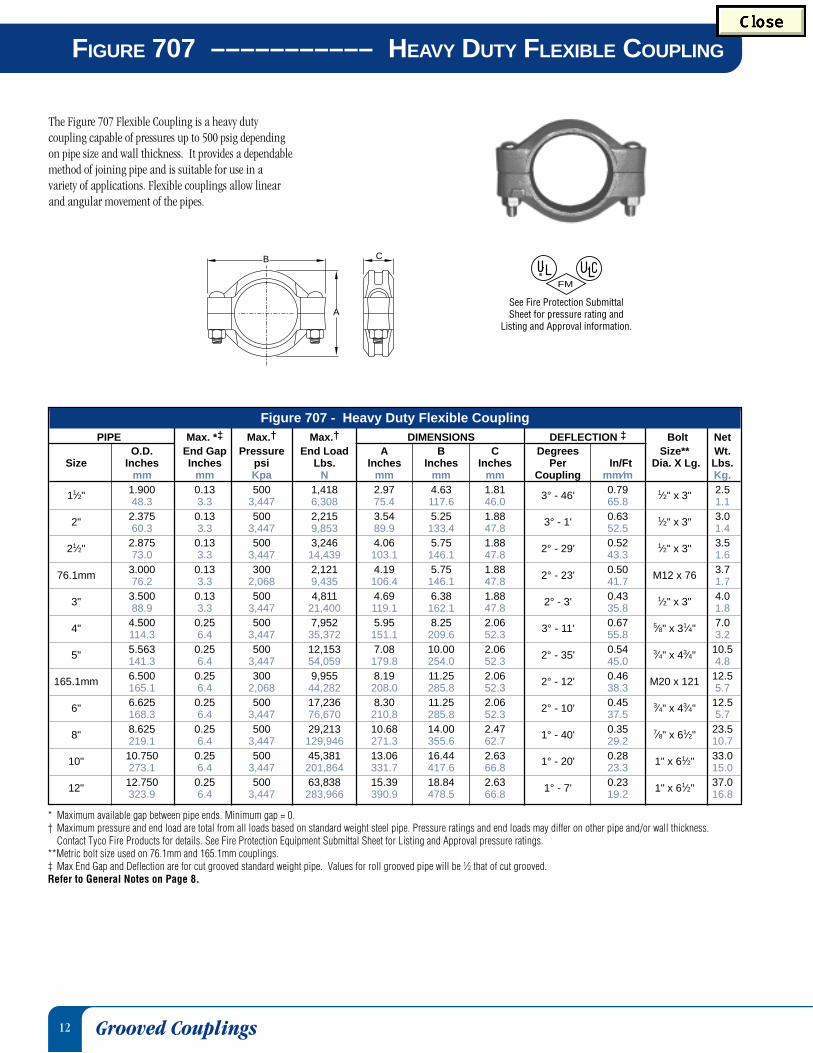
FIGURE 707 ––––––––––– HEAVY DUTY FLEXIBLE COUPLING
* Maximum available gap between pipe ends. Minimum gap = 0.† Maximum pressure and end load are total from all loads based on standard weight steel pipe. Pressure ratings and end loads may differ on other pipe and/or wall thickness.
Contact Tyco Fire Products for details. See Fire Protection Equipment Submittal Sheet for Listing and Approval pressure ratings.**Metric bolt size used on 76.1mm and 165.1mm couplings.‡ Max End Gap and Deflection are for cut grooved standard weight pipe. Values for roll grooved pipe will be 1⁄2 that of cut grooved.Refer to General Notes on Page 8.
B
A
C
Grooved Couplings
The Figure 707 Flexible Coupling is a heavy dutycoupling capable of pressures up to 500 psig dependingon pipe size and wall thickness. It provides a dependablemethod of joining pipe and is suitable for use in avariety of applications. Flexible couplings allow linearand angular movement of the pipes.
FM
See Fire Protection Submittal Sheet for pressure rating and
Listing and Approval information.
Figure 707 - Heavy Duty Flexible CouplingPIPE Max. *‡ Max.† Max.† DIMENSIONS DEFLECTION ‡ Bolt Net
O.D. End Gap Pressure End Load A B C Degrees Size** Wt.Size Inches Inches psi Lbs. Inches Inches Inches Per In/Ft Dia. X Lg. Lbs.
mm mm Kpa N mm mm mm Coupling mm⁄m Kg.
11⁄2" 1.900 0.13 500 1,418 2.97 4.63 1.81 3° - 46' 0.79 1⁄2" x 3" 2.548.3 3.3 3,447 6,308 75.4 117.6 46.0 65.8 1.1
2" 2.375 0.13 500 2,215 3.54 5.25 1.88 3° - 1' 0.63 1⁄2" x 3" 3.060.3 3.3 3,447 9,853 89.9 133.4 47.8 52.5 1.4
21⁄2" 2.875 0.13 500 3,246 4.06 5.75 1.88 2° - 29' 0.52 1⁄2" x 3" 3.573.0 3.3 3,447 14,439 103.1 146.1 47.8 43.3 1.6
76.1mm 3.000 0.13 300 2,121 4.19 5.75 1.88 2° - 23' 0.50 M12 x 76 3.776.2 3.3 2,068 9,435 106.4 146.1 47.8 41.7 1.7
3" 3.500 0.13 500 4,811 4.69 6.38 1.88 2° - 3' 0.43 1⁄2" x 3" 4.088.9 3.3 3,447 21,400 119.1 162.1 47.8 35.8 1.8
4" 4.500 0.25 500 7,952 5.95 8.25 2.06 3° - 11' 0.67 5⁄8" x 31⁄4" 7.0114.3 6.4 3,447 35,372 151.1 209.6 52.3 55.8 3.2
5" 5.563 0.25 500 12,153 7.08 10.00 2.06 2° - 35' 0.54 3⁄4" x 43⁄4" 10.5141.3 6.4 3,447 54,059 179.8 254.0 52.3 45.0 4.8
165.1mm 6.500 0.25 300 9,955 8.19 11.25 2.06 2° - 12' 0.46 M20 x 121 12.5165.1 6.4 2,068 44,282 208.0 285.8 52.3 38.3 5.7
6" 6.625 0.25 500 17,236 8.30 11.25 2.06 2° - 10' 0.45 3⁄4" x 43⁄4" 12.5168.3 6.4 3,447 76,670 210.8 285.8 52.3 37.5 5.7
8" 8.625 0.25 500 29,213 10.68 14.00 2.47 1° - 40' 0.35 7⁄8" x 61⁄2" 23.5219.1 6.4 3,447 129,946 271.3 355.6 62.7 29.2 10.7
10" 10.750 0.25 500 45,381 13.06 16.44 2.63 1° - 20' 0.28 1" x 61⁄2" 33.0273.1 6.4 3,447 201,864 331.7 417.6 66.8 23.3 15.0
12" 12.750 0.25 500 63,838 15.39 18.84 2.63 1° - 7' 0.23 1" x 61⁄2" 37.0323.9 6.4 3,447 283,966 390.9 478.5 66.8 19.2 16.8
13
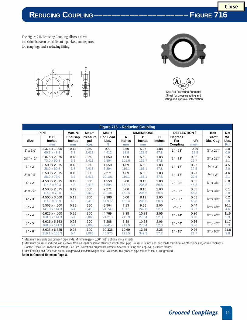
The Figure 716 Reducing Coupling allows a directtransition between two different pipe sizes, and replacestwo couplings and a reducing fitting.
REDUCING COUPLING––––––––––––––––––––– FIGURE 716
* Maximum available gap between pipe ends. Minimum gap = 0.06" (with optional metal insert).† Maximum pressure and end load are total from all loads based on standard weight steel pipe. Pressure ratings and end loads may differ on other pipe and/or wall thickness.
Contact Tyco Fire Products for details. See Fire Protection Equipment Submittal Sheet for Listing and Approval pressure ratings.‡ Max End Gap and Deflection are for cut grooved standard weight pipe. Values for roll grooved pipe will be 1⁄2 that of cut grooved.Refer to General Notes on Page 8.
FM
See Fire Protection Submittal Sheet for pressure rating and
Listing and Approval information.
Grooved Couplings
Figure 716 - Reducing CouplingPIPE Max. *‡ Max.† Max.† DIMENSIONS DEFLECTION ‡ Bolt Net
O.D. End Gap Pressure End Load A B C Degrees Size** Wt.Size Inches Inches psi Lbs. Inches Inches Inches Per In/Ft Dia. X Lg. Lbs.
mm mm Kpa N mm mm mm Coupling mm⁄m Kg.
2" x 11⁄2" 2.375 x 1.900 0.13 350 992 3.50 5.06 1.88 1° - 53' 0.39 3⁄8" x 21⁄4" 2.060.3 x 48.8 3.3 2,413 4,412 88.9 128.5 47.8 32.5 0.9
21⁄2" x 2" 2.875 x 2.375 0.13 350 1,550 4.00 5.50 1.88 1° - 33' 0.32 3⁄8" x 21⁄4" 2.573.0 x 60.3 3.3 2,413 6,894 101.6 139.7 47.8 26.7 1.1
3" x 2" 3.500 x 2.375 0.13 350 1,550 4.69 6.50 1.88 1° - 17' 0.27 1⁄2" x 3" 4.588.9 x 60.3 3.3 2,413 6,894 119.1 165.1 47.8 22.5 2.0
3" x 21⁄2" 3.500 x 2.875 0.13 350 2,271 4.69 6.50 1.88 1° - 17' 0.27 1⁄2" x 3" 4.688.9 x 73.0 3.3 2,413 10,101 119.1 165.1 47.8 22.5 2.1
4" x 2" 4.500 x 2.375 0.19 350 1,550 6.00 8.13 2.00 2° - 38' 0.55 5⁄8" x 31⁄4" 6.0114.3 x 60.3 4.8 2,413 6,894 152.4 206.5 50.8 45.8 2.7
4" x 21⁄2" 4.500 x 2.875 0.19 350 2,271 6.00 8.13 2.00 2° - 38' 0.55 5⁄8" x 31⁄4" 6.1114.3 x 73.0 4.8 2,413 10,101 152.4 206.5 50.8 45.8 2.8
4" x 3" 4.500 x 3.500 0.19 350 3,366 6.00 8.13 2.00 2° - 38' 0.55 5⁄8" x 31⁄4" 6.2114.3 x 88.9 4.8 2,413 14,972 152.4 206.5 50.8 45.8 2.8
5" x 4" 5.563 x 4.500 0.25 350 5,564 7.13 9.56 2.06 2° - 5' 0.44 3⁄4" x 43⁄4" 10.1141.3 x 114.3 6.4 2,413 24,749 181.1 242.8 52.3 36.7 4.6
6" x 4" 6.625 x 4.500 0.25 300 4,769 8.38 10.88 2.06 1° - 44' 0.36 3⁄4" x 43⁄4" 11.6168.3 x 114.3 6.4 2,068 21,213 212.9 276.4 52.3 30.0 5.3
6" x 5" 6.625 x 5.563 0.25 300 7,288 8.38 10.88 2.06 1° - 44' 0.36 3⁄4" x 43⁄4" 11.7168.3 x 141.3 6.4 2,068 32,417 212.9 276.4 52.3 30.0 5.3
8" x 6" 8.625 x 6.625 0.25 300 10,336 10.69 13.75 2.25 1° - 15' 0.26 7⁄8" x 61⁄2" 21.6219.1 x 168.3 6.4 2,068 45,975 271.5 349.3 57.2 21.7 9.8
14
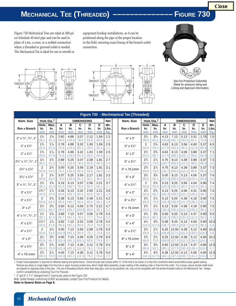
MECHANICAL TEE (THREADED) –––––––––––––– FIGURE 730
Figure 730 Mechanical Tees are rated at 300 psion Schedule 40 steel pipe and can be used inplace of a tee, a cross, or a welded connectionwhere a threaded or grooved outlet is needed.The Mechanical Tee is ideal for use in retrofit or
B
A
A
C
DTAKEOUT
DTAKEOUT
B
A
E
DTAKEOUT
C
† Proper hole preparation is required for effective sealing and performance. Check the pipe seal surface within 5⁄8" of the hole to be certain it is free from conditions which would affect proper gasket sealing.Remove any sharp or rough edges from the hole or upper housing contact area, which might affect assembly, proper seating of the locating collar or flow from the outlet. For crosses, ensure double outlet holesare aligned on opposite sides of the pipe. The use of threaded products other than steel pipe, such as dry pendents, etc. may not be compatible with the female threaded outlet on the Mechanical Tee. Alwaysconfirm compatibility by contacting Tyco Fire Products.
* 3" and 4" x 11⁄4" changed from 2" previously used on the Figure 720.Note: Outlet threads conforming to BSP are available; contact Tyco Fire Products for details.Refer to General Notes on Page 8.
FM
See Fire Protection Submittal Sheet for pressure rating and
Listing and Approval information.
Mechanical Outlets
equipment hookup installations, as it can bepositioned along the pipe at the proper locationin the field, ensuring exact lineup of the branch outletconnection.
Nom. Size Hole Dia.† DIMENSIONS NetHole Max. A B C D E Wt.
Run x Branch In. In. In. In. In. In. In. Lbs.mm mm mm mm mm mm mm Kg.
4" x 3" 31⁄2 35⁄8 4.13 7.13 5.13 3.31 2.78 7.088.9 92.1 104.9 181.1 130.3 84.1 70.6 3.2
5" x 11⁄2" 2 21⁄8 4.63 8.13 3.56 4.00 3.37 6.550.8 54.0 117.6 206.5 90.4 101.6 85.6 2.9
5" x 2" 21⁄2 25⁄8 4.63 8.13 4.06 3.88 3.37 7.163.5 66.7 117.6 206.5 103.1 98.6 85.6 3.2
5" x 21⁄2" 23⁄4 27⁄8 4.75 8.13 4.38 3.88 3.37 7.369.9 73.0 120.7 206.5 111.3 98.6 85.6 3.3
5" x 76.1mm 23⁄4 27⁄8 4.75 8.13 4.38 3.88 3.37 7.369.9 73.0 120.7 206.5 111.3 98.6 85.6 3.3
5" x 3" 31⁄2 35⁄8 5.00 8.13 5.13 4.06 3.37 7.688.9 92.1 127.0 206.5 130.3 103.1 85.6 3.4
6" x 11⁄2" 2 21⁄8 5.13 9.25 3.56 4.04 3.90 7.450.8 54.0 130.3 235.0 90.4 102.6 99.1 3.4
6" x 2" 21⁄2 25⁄8 5.13 9.25 4.06 4.31 3.90 7.550.8 66.7 130.3 235.0 103.1 109.5 99.1 3.4
6" x 21⁄2" 23⁄4 27⁄8 5.13 9.25 4.38 4.18 3.90 7.569.9 73.0 130.3 235.0 111.3 106.2 99.1 3.4
6" x 76.1mm 23⁄4 27⁄8 5.13 9.25 4.38 4.18 3.90 7.569.9 73.0 130.3 235.0 111.3 106.2 99.1 3.4
6" x 3" 31⁄2 35⁄8 5.50 9.25 5.13 4.37 3.90 9.588.9 92.1 139.7 235.0 130.3 111.0 99.1 4.3
6" x 4" 41⁄2 45⁄8 5.38 9.25 6.13 4.56 3.90 10.0114.3 117.5 136.7 235.0 155.7 115.8 99.1 4.5
8" x 21⁄2" 23⁄4 27⁄8 6.25 12.50 4.38 5.12 4.90 10.269.9 73.0 158.8 317.5 111.3 130.0 124.5 4.6
8" x 76.1mm 23⁄4 27⁄8 6.25 12.50 4.38 5.12 4.90 10.269.9 73.0 158.8 317.5 111.3 130.0 124.5 4.6
8" x 3" 31⁄2 35⁄8 6.50 12.50 5.13 5.37 4.90 12.588.9 92.1 165.1 317.5 130.3 136.4 124.5 5.7
8" x 4" 41⁄2 45⁄8 6.38 12.50 6.13 5.56 4.90 12.5114.3 117.5 162.1 317.5 155.7 141.2 124.5 5.7
Nom. Size Hole Dia.† DIMENSIONS NetHole Max. A B C D E Wt.
Run x Branch In. In. In. In. In. In. In. Lbs.mm mm mm mm mm mm mm Kg.
2" x 1⁄2", 3⁄4", 1" 11⁄2 15⁄8 2.62 4.88 3.07 2.12 1.59 2.238.1 41.3 66.5 124.0 78.0 53.8 40.4 1.0
2" x 11⁄4" 13⁄4 17⁄8 2.78 4.88 3.32 1.93 1.59 2.544.5 47.6 70.6 124.0 84.3 49.0 40.4 1.1
2" x 11⁄2" 13⁄4 17⁄8 2.78 4.88 3.32 1.93 1.59 2.544.5 47.6 70.6 124.0 84.3 49.0 40.4 1.1
21⁄2" x 1⁄2", 3⁄4", 1" 11⁄2 15⁄8 2.88 5.25 3.07 2.38 1.81 2.738.1 41.3 73.2 133.4 78.0 60.5 46.0 1.2
21⁄2" x 11⁄4" 2 21⁄8 3.00 5.25 3.56 2.19 1.81 3.150.8 54.0 76.2 133.4 90.4 55.6 46.0 1.4
21⁄2" x 11⁄2" 2 21⁄8 3.07 5.25 3.59 2.17 1.81 3.350.8 54.0 78.0 133.4 91.2 55.1 46.0 1.5
3" x 1⁄2", 3⁄4", 1" 11⁄2 15⁄8 3.19 6.13 3.07 2.56 2.21 3.738.1 41.3 81.0 155.7 78.0 65.0 56.1 1.7
3" x 11⁄4" 13⁄4 * 17⁄8 3.34 6.13 3.32 2.50 2.21 3.944.5 47.6 84.8 155.7 84.3 63.5 56.1 1.8
3" x 11⁄2" 2 21⁄8 3.38 6.13 3.56 2.48 2.21 4.250.8 54.0 85.9 155.7 90.4 63.0 56.1 1.9
3" x 2" 21⁄2 25⁄8 3.50 6.13 4.09 2.75 2.21 4.763.5 66.7 88.9 155.7 103.9 69.9 56.1 2.1
4" x 1⁄2", 3⁄4", 1" 11⁄2 15⁄8 3.69 7.13 3.07 3.06 2.78 5.538.1 41.3 93.7 181.1 78.0 77.7 70.6 2.5
4" x 11⁄4" 13⁄4 * 17⁄8 3.92 7.13 3.32 3.00 2.78 5.544.5 47.6 99.6 181.1 84.3 76.2 70.6 2.5
4" x 11⁄2" 2 21⁄8 4.00 7.13 3.56 2.98 2.78 5.550.8 54.0 101.6 181.1 90.4 75.7 70.6 2.5
4" x 2" 21⁄2 25⁄8 4.00 7.13 4.06 3.25 2.78 6.063.5 66.7 101.6 181.1 103.1 82.6 70.6 2.7
4" x 21⁄2" 23⁄4 27⁄8 4.00 7.13 4.38 3.12 2.78 6.069.9 73.0 101.6 181.1 111.3 79.2 70.6 2.7
4" x 76.1mm 23⁄4 27⁄8 4.00 7.13 4.38 3.12 2.78 6.069.9 73.0 101.6 181.1 111.3 79.2 70.6 2.7
Figure 730 - Mechmanical Tee (Threaded)
15
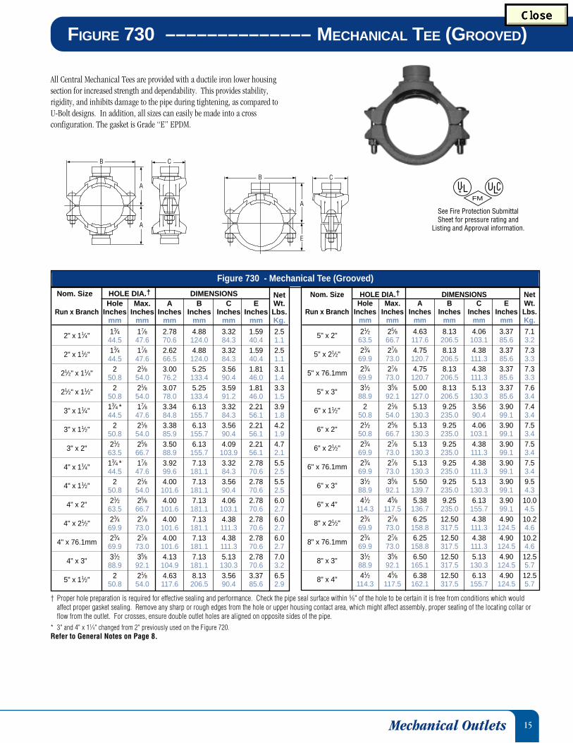
MECHANICAL OUTLETSFIGURE 730 –––––––––––––– MECHANICAL TEE (GROOVED)
All Central Mechanical Tees are provided with a ductile iron lower housingsection for increased strength and dependability. This provides stability,rigidity, and inhibits damage to the pipe during tightening, as compared toU-Bolt designs. In addition, all sizes can easily be made into a crossconfiguration. The gasket is Grade “E” EPDM.
† Proper hole preparation is required for effective sealing and performance. Check the pipe seal surface within 5⁄8" of the hole to be certain it is free from conditions which wouldaffect proper gasket sealing. Remove any sharp or rough edges from the hole or upper housing contact area, which might affect assembly, proper seating of the locating collar orflow from the outlet. For crosses, ensure double outlet holes are aligned on opposite sides of the pipe.
* 3" and 4" x 11⁄4" changed from 2" previously used on the Figure 720.Refer to General Notes on Page 8.
B
A
A
C
A
E
B C
FM
See Fire Protection Submittal Sheet for pressure rating and
Listing and Approval information.
Mechanical Outlets
Nom. Size HOLE DIA.† DIMENSIONS NetHole Max. A B C E Wt.
Run x Branch Inches Inches Inches Inches Inches Inches Lbs.mm mm mm mm mm mm Kg.
2" x 11⁄4" 13⁄4 17⁄8 2.78 4.88 3.32 1.59 2.544.5 47.6 70.6 124.0 84.3 40.4 1.1
2" x 11⁄2" 13⁄4 17⁄8 2.62 4.88 3.32 1.59 2.544.5 47.6 66.5 124.0 84.3 40.4 1.1
21⁄2" x 11⁄4" 2 21⁄8 3.00 5.25 3.56 1.81 3.150.8 54.0 76.2 133.4 90.4 46.0 1.4
21⁄2" x 11⁄2" 2 21⁄8 3.07 5.25 3.59 1.81 3.350.8 54.0 78.0 133.4 91.2 46.0 1.5
3" x 11⁄4" 13⁄4 * 17⁄8 3.34 6.13 3.32 2.21 3.944.5 47.6 84.8 155.7 84.3 56.1 1.8
3" x 11⁄2" 2 21⁄8 3.38 6.13 3.56 2.21 4.250.8 54.0 85.9 155.7 90.4 56.1 1.9
3" x 2" 21⁄2 25⁄8 3.50 6.13 4.09 2.21 4.763.5 66.7 88.9 155.7 103.9 56.1 2.1
4" x 11⁄4" 13⁄4 * 17⁄8 3.92 7.13 3.32 2.78 5.544.5 47.6 99.6 181.1 84.3 70.6 2.5
4" x 11⁄2" 2 21⁄8 4.00 7.13 3.56 2.78 5.550.8 54.0 101.6 181.1 90.4 70.6 2.5
4" x 2" 21⁄2 25⁄8 4.00 7.13 4.06 2.78 6.063.5 66.7 101.6 181.1 103.1 70.6 2.7
4" x 21⁄2" 23⁄4 27⁄8 4.00 7.13 4.38 2.78 6.069.9 73.0 101.6 181.1 111.3 70.6 2.7
4" x 76.1mm 23⁄4 27⁄8 4.00 7.13 4.38 2.78 6.069.9 73.0 101.6 181.1 111.3 70.6 2.7
4" x 3" 31⁄2 35⁄8 4.13 7.13 5.13 2.78 7.088.9 92.1 104.9 181.1 130.3 70.6 3.2
5" x 11⁄2" 2 21⁄8 4.63 8.13 3.56 3.37 6.550.8 54.0 117.6 206.5 90.4 85.6 2.9
Nom. Size HOLE DIA.† DIMENSIONS NetHole Max. A B C E Wt.
Run x Branch Inches Inches Inches Inches Inches Inches Lbs.mm mm mm mm mm mm Kg.
5" x 2" 21⁄2 25⁄8 4.63 8.13 4.06 3.37 7.163.5 66.7 117.6 206.5 103.1 85.6 3.2
5" x 21⁄2" 23⁄4 27⁄8 4.75 8.13 4.38 3.37 7.369.9 73.0 120.7 206.5 111.3 85.6 3.3
5" x 76.1mm 23⁄4 27⁄8 4.75 8.13 4.38 3.37 7.369.9 73.0 120.7 206.5 111.3 85.6 3.3
5" x 3" 31⁄2 35⁄8 5.00 8.13 5.13 3.37 7.688.9 92.1 127.0 206.5 130.3 85.6 3.4
6" x 11⁄2" 2 21⁄8 5.13 9.25 3.56 3.90 7.450.8 54.0 130.3 235.0 90.4 99.1 3.4
6" x 2" 21⁄2 25⁄8 5.13 9.25 4.06 3.90 7.550.8 66.7 130.3 235.0 103.1 99.1 3.4
6" x 21⁄2" 23⁄4 27⁄8 5.13 9.25 4.38 3.90 7.569.9 73.0 130.3 235.0 111.3 99.1 3.4
6" x 76.1mm 23⁄4 27⁄8 5.13 9.25 4.38 3.90 7.569.9 73.0 130.3 235.0 111.3 99.1 3.4
6" x 3" 31⁄2 35⁄8 5.50 9.25 5.13 3.90 9.588.9 92.1 139.7 235.0 130.3 99.1 4.3
6" x 4" 41⁄2 45⁄8 5.38 9.25 6.13 3.90 10.0114.3 117.5 136.7 235.0 155.7 99.1 4.5
8" x 21⁄2" 23⁄4 27⁄8 6.25 12.50 4.38 4.90 10.269.9 73.0 158.8 317.5 111.3 124.5 4.6
8" x 76.1mm 23⁄4 27⁄8 6.25 12.50 4.38 4.90 10.269.9 73.0 158.8 317.5 111.3 124.5 4.6
8" x 3" 31⁄2 35⁄8 6.50 12.50 5.13 4.90 12.588.9 92.1 165.1 317.5 130.3 124.5 5.7
8" x 4" 41⁄2 45⁄8 6.38 12.50 6.13 4.90 12.5114.3 117.5 162.1 317.5 155.7 124.5 5.7
Figure 730 - Mechanical Tee (Grooved)
16
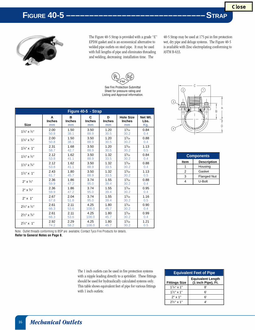
FIGURE 40-5 ––––––––––––––––––––––––––––––STRAP
The Figure 40-5 Strap is provided with a grade “E”EPDM gasket and is an economical alternative towelded pipe outlets on steel pipe. It may be usedwith full lengths of pipe and eliminates threadingand welding, decreasing installation time. The
The 1 inch outlets can be used in fire protection systemswith a nipple leading directly to a sprinkler. These fittingsshould be used for hydraulically calculated systems only.This table shows equivalent feet of pipe for various fittingswith 1 inch outlets:
Note: Outlet threads conforming to BSP are available; Contact Tyco Fire Products for details.Refer to General Notes on Page 8.
FM
See Fire Protection Submittal Sheet for pressure rating and
Listing and Approval information.
40-5 Strap may be used at 175 psi in fire protectionwet, dry pipe and deluge systems. The Figure 40-5is available with Zinc electroplating conforming toASTM B-633.
Mechanical Outlets
Figure 40-5 - StrapA B C D Hole Size Net Wt.
Inches Inches Inches Inches Inches Lbs.Size mm mm mm mm mm Kg.
11⁄4" x 1⁄2" 2.00 1.50 3.50 1.20 13⁄16 0.8450.8 38.1 88.9 30.5 30.2 0.4
11⁄4" x 3⁄4" 2.00 1.50 3.50 1.20 13⁄16 0.8850.8 38.1 88.9 30.5 30.2 0.4
11⁄4" x 1" 2.31 1.68 3.50 1.20 13⁄16 1.1358.7 42.7 88.9 30.5 30.2 0.5
11⁄2" x 1⁄2" 2.12 1.62 3.50 1.32 13⁄16 0.8453.8 41.1 88.9 33.5 30.2 0.4
11⁄2" x 3⁄4" 2.12 1.62 3.50 1.32 13⁄16 0.8853.8 41.1 88.9 33.5 30.2 0.4
11⁄2" x 1" 2.43 1.80 3.50 1.32 13⁄16 1.1361.7 45.7 88.9 33.5 30.2 0.5
2" x 1⁄2" 2.36 1.86 3.74 1.55 13⁄16 0.8859.9 47.2 95.0 39.4 30.2 0.4
2" x 3⁄4" 2.36 1.86 3.74 1.55 13⁄16 0.9559.9 47.2 95.0 39.4 30.2 0.4
2" x 1" 2.67 2.04 3.74 1.55 13⁄16 1.1667.8 51.8 95.0 39.4 30.2 0.5
21⁄2" x 1⁄2" 2.61 2.11 4.25 1.80 13⁄16 0.9066.3 53.6 108.0 45.7 30.2 0.4
21⁄2" x 3⁄4" 2.61 2.11 4.25 1.80 13⁄16 0.9966.3 53.6 108.0 45.7 30.2 0.4
21⁄2" x 1" 2.92 2.29 4.25 1.80 13⁄16 1.2174.2 58.2 108.0 45.7 30.2 0.5
Equivalent Feet of PipeEquivalent Length
Fittings Size (1 inch Pipe), Ft.11/4" x 1" 8'
11⁄2" x 1" 6'
2" x 1" 6'
21⁄2" x 1" 4'
ComponentsItem Description
1 Housing
2 Gasket
3 Flanged Nut
4 U-Bolt

17
† Maximum pressure and end load are total from all loads based on standard weight steel pipe. Pressure ratings and end loads may differ on other pipe and/or wall thickness. ContactTyco Fire Products for details. See Fire Protection Equipment Submittal Sheet for Listing and Approval pressure ratings.
* Dimensions D and E represent minimum and maximum sealing surfaces.**Bolts are not supplied. Bolt lengths shown are standard; it is the responsibility of the purchaser to verify correct length for the intended application.Refer to General Notes on Page 8.
CA
F B E D
The Figure 71 Flange Adapter allows a directtransition from flanged components to agrooved piping system. Flange bolt patternsconform to ANSI Class 125 and 150 standards.
FIGURE 71 ––––––––––––––––––––––– FLANGE ADAPTER
FM
See Fire Protection Submittal Sheet for pressure rating and
Listing and Approval information.
Flange Adapter
The gasket seal is designed with optimum amountof rubber to provide a dependable seal and alsoavoid the overfilling of the gasket pocket thatmakes assembly difficult.
Figure 71 - Flange AdapterPIPE Max.† Max.† DIMENSIONS BOLTS Net
O.D. Pressure End Load A B C D* E* F Size** Wt.Size Inches psi lbs Inches Inches Inches Inches Inches Inches Dia. X Lg. Qty. Lbs.
mm Kpa Kg mm mm mm mm mm mm Kg.
2" 2.375" 250 1,107 6.38 4.75 0.75 2.38 3.41 7.25 5⁄8" x 3" 4 3.01,724 4,924 162.1 120.7 19.1 60.5 86.6 184.2 1.4
21⁄2" 2.875" 250 1,622 7.00 5.50 0.88 2.88 3.91 7.88 5⁄8" x 3" 4 5.01,724 7,215 178.0 140.0 22.0 73.0 99.0 200.0 2.3
3" 3.500" 250 2,404 7.50 6.00 0.94 3.50 4.53 9.88 5⁄8" x 3" 4 5.61,724 10,693 190.5 152.4 23.9 88.9 115.1 251.0 2.5
4" 4.500" 250 3,974 9.00 7.50 0.94 4.50 5.53 9.90 5⁄8" x 3" 8 7.01,724 17,676 228.6 190.5 23.9 114.3 140.5 251.5 3.2
5" 5.563" 250 6,073 10.00 8.50 1.00 5.56 6.72 11.38 3⁄4" x 31⁄2" 8 9.21,724 27,013 254.0 215.9 25.4 141.2 170.7 289.1 4.2
6" 6.625" 250 8,614 11.00 9.50 1.00 6.62 7.78 11.88 3⁄4" x 31⁄2" 8 10.01,724 38,315 279.4 241.3 25.4 168.1 197.6 301.8 4.5
8" 8.625" 250 14,599 13.50 11.75 1.13 8.62 9.94 14.38 3⁄4" x 31⁄2" 8 16.61,724 64,936 342.9 298.5 28.7 218.9 252.5 365.3 7.5
10" 10.750" 250 22,679 16.00 14.25 1.19 10.75 12.31 16.88 7⁄8" x 4" 12 21.81,724 100,876 406.4 362.0 30.2 273.1 312.7 428.8 9.9
12" 12.750" 250 31,903 19.00 17.00 1.25 12.75 14.31 20.00 7⁄8" x 4" 12 24.21,724 141,905 482.6 431.8 31.8 323.9 363.5 508.0 11.0

18
Figure 219/519
d - These fittings are only available in domestic ductile iron. All other sizesare fabricated steel.
‡ - Sizes 11⁄4" thru 12" are available with 1⁄2" and 1" tap plug, sizes 14" thru24" are fabricated dished end caps.
* - These sizes can also be ordered in the Figure 110 which is cast ductileiron purchased from a foreign supplier.
† - These sizes can also be ordered in the Figure 111 which is cast ductileiron purchased from a foreign supplier.
** - These sizes can also be ordered in the Figure 120 which is cast ductileiron purchased form a foreign supplier.
Refer to General Notes on Page 8.
C to E
C to E
Figure 201/501
C to E
C to E
Central Grooved fittings provide an economical andefficient method of changing direction, adding anoutlet, reducing, or capping grooved piping systems.Central fittings are available in durable ductile iron(indicated by note “d" ), stainless steel, and fabricated
FITTINGS ––––––––– FIGURE 201, 210, 219, 501, 510, 519
steel. Grooved fittings are rated at the pressure ratingof the coupling, and pipe being used, not to exceed themaximum rating in the chart at the bottom of thispage. Series 300 and 501, 510, 510 DE and 519grooved fittings maximum rating 300 psi.
C to E
C to E
Figure 210/510
Grooved Fittings
Figure 201, 210, 219, 501, 510, 519 - FittingsFIGURE 201 FIGURE 501 FIGURE 210 FIGURE 510 FIGURE 219 FIGURE 51945° ELBOW 45° ELBOW 90° ELBOW 90° ELBOW TEE TEE
Nominal C to E Appx. Wt. C to E Appx. Wt. C to E Appx. Wt. C to E Appx. Wt. C to E Appx. Wt. C to E Appx. Wt.Size Inches Lbs. Inches Lbs. Inches Lbs. Inches Lbs. Inches Lbs. Inches Lbs.
Inches mm Kg. mm Kg. mm Kg. mm Kg. mm Kg. mm Kg.
11⁄4" 1.75d 0.9 1.75d 0.8 2.75d 1 2.75d 1 2.75d 1.4 2.75d 1.444.5 0.4 44.5 0.4 69.9 0.5 69.9 0.5 69.9 0.6 69.9 0.6
11⁄2" 1.75d 1.1 1.75d 1 2.75d 1.2 2.75d 1.4 2.75d 1.8 2.75d 1.844.5 0.5 44.5 0.5 69.9 0.5 69.9 0.6 69.9 0.8 69.9 0.8
2" 2.00d 1.8 2d 1.3 3.25d 2 3.25d 1.8 3.25d 2.7 3.25d 2.650.8 0.8 50.8 0.6 82.6 0.9 82.6 0.8 82.6 1.2 82.6 1.2
21⁄2" 2.25d 2.2 2.25d 1.9 3.75d 3 3.75d 2.7 3.75d 5.8 3.75d 3.957.2 1.0 57.2 0.9 95.3 1.4 95.3 1.2 95.3 2.6 95.3 1.8
76.1mm 2.25d 2.2 - - 3.75d 3 - - 3.75d 5.8 - -57.2 1.0 95.3 1.4 95.3 2.6
3" 2.50d 3.5 2.50d 2.6 4.25d 4.5 4.25d 3.7 4.25d 7.0 4.25d 5.463.5 1.6 63.5 1.2 108 2 108 1.7 108 3.2 108 2.4
4" 3.00d 5.2 3d 5 5.00d 8.5 5.00d 7.0 5.00d 11.8 5.00d 10.176.2 2.4 76.2 2.3 127 3.9 127 3.2 127 5.4 127 4.6
5" 3.25d 8.5 3.50d 8.6 5.50d 13.5 6.5d 13.4 5.50d 17.0 6.50d 18.882.6 3.9 88.9 3.9 139.7 6.1 165.1 6.1 139.7 7.7 165.1 8.5
165.1mm 3.50d 12.0 - - 6.50d 18.5 - - 6.50d 26.0 - -88.9 5.4 165.1 8.4 165.1 11.8
6" 3.50d 12.0 4.25d 17.2 6.50d 18.5 7.75d 26.3 6.50d 26.0 7.75d 36.388.9 5.4 108 7.8 165.1 8.4 196.9 11.9 165.1 11.8 196.9 16.5
8" 4.25d 23.0 - - 7.75d 36.5 - - 7.75d 45.0 - -108 10.4 196.9 16.6 196.9 20.4
10" 4.75d,† 31.0 - - 9.00d,* 60 - - 9.00d,** 72.1 - -120.7 14.1 228.6 27.2 228.6 32.7
12" 5.25d,† 40.0 - - 10.00d,* 67 - - 10.00d,** 92.5 - -133.4 18.1 254 30.4 254 42
FM
See Fire Protection Submittal Sheet for pressure rating and
Listing and Approval information.
Figure 201, 210, 219 - FittingsRATED PRESSURE (psi)
NominalFigure Size
(Inches)11⁄4" - 3" 500 500 500
201 76.1mm 300 - 300210 4" 500 400 500219 5" 500 500 500
165.1mm 300 - 3006" 400 400 400
8" - 12" 450 450 450
FM

19
C to E
C to E
C to E
C to E
C to E
C to E
Figure 327
Figure 313
Figure 312
Refer to General Notes on Page 8.
Grooved Fittings
FITTINGS & END CAP –––––––– FIGURE 260, 312, 313, 327
Figure 312, 313, 327 - FittingsFIGURE 312 FIGURE 313 FIGURE 327
221/2° ELBOW 111/4° ELBOW CROSS
Nominal C to E Appx. Wt. C to E Appx. Wt. C to E Appx. Wt.Size Inches Lbs. Inches Lbs. Inches Lbs.
Inches mm Kg. mm Kg. mm Kg.
11/4" 1.75 0.4 1.38 0.4 2.75 2.044.5 0.2 35.1 0.2 69.9 0.9
11/2" 1.75 0.5 1.38 0.5 2.75 2.244.5 0.2 35.1 0.2 69.9 1.0
2" 1.88 0.6 1.38 0.6 3.25 2.747.8 0.3 35.1 0.3 82.6 1.2
21/2" 2.00 0.7 1.50 1.1 3.75 5.050.8 0.3 38.1 0.5 95.3 2.3
3" 2.25 1.4 1.50 1.2 4.25 7.157.2 0.6 38.1 0.5 108.0 3.2
4" 2.63 2.4 1.75 2.2 5.00 11.966.8 1.1 44.5 1.0 127.0 5.4
5" 2.88 4.1 2.00 3.3 5.50 17.173.2 1.9 50.8 1.5 139.7 7.8
6" 3.13 5.6 2.00 4.6 6.50 27.579.5 2.5 50.8 2.1 165.1 12.5
8" 3.88 11.1 2.00 8.7 7.75 47.098.6 5.0 50.8 3.9 196.9 21.3
10" 4.38 14.0 2.13 9.1 9.00 68.0111.3 6.4 54.1 4.1 228.6 30.8
12" 4.88 22.0 2.25 16.7 10.00 107.0124.0 10.0 57.2 7.6 254.0 48.5
E to E
Figure 260Sizes 11⁄4" - 12"
FM
See Fire Protection Submittal Sheet for pressure rating and
Listing and Approval information.
Figure 260‡ - End CapNominal C to E Appx. Wt. Rated Pressure (psi)
Size Inches Lbs.Inches mm Kg.
11/4" 0.88d 0.4 500 500 50022.4 0.2
11/2" 0.88d 0.6 500 500 50022.4 0.3
2" 0.88d 0.9 500 500 50022.4 0.4
21/2" 0.88d 0.9 500 500 50022.4 0.4
76.1mm 0.94d 1.1 300 - 30023.9 0.5
3" 0.88d 1.1 500 500 50022.4 0.5
4" 1.00d 2.6 500 500 50025.4 1.2
5" 1.00d 5.0 400 400 40025.4 2.3
165.1mm 1.00d 7.5 300 - 30025.4 3.4
6" 1.00d 7.5 400 400 40025.4 3.4
8" 1.19d 12.8 450 450 45030.2 5.8
10" 1.25d 20.0 450 450 45031.8 9.1
12" 1.25d 36.0 250 250 25031.8 16.3
FM
d - These fittings are available in domestic ductile iron.‡ - Sizes 11⁄4" thru 12" are available with 1⁄2", 3⁄4" and 1" tap plug. Figure 260 end caps are
constructed of durable ductile iron.Refer to General Notes on Page 8.

20
C to GE
C to TE
Figure 315
Figure 320
Figure 510DE
Figure 341
* - Figure 510 DE 90° Drain Elbows have a standard 1" female threaded outletRefer to General Notes on Page 8.
C to GE
C to TEE to E
FITTINGS –––––––––––––– FIGURE 315, 320, 341, 510 DE
Grooved Fittings
Figure 315, 320, 326, 341 - FittingsFIGURE 315 FIGURE 320 FIGURE 341GR. X THD GR. X GR. X THD 150 LBS. FIGURE 510 DE90° ELBOW TEE FLANGE ADAPTER 90° DRIAN ELBOW
Nominal C to GE C to TE Appx. Wt. C to GE C to TE Appx. Wt. E to E Appx. Wt. C to E A B Appx. Wt.Size Inches Inches Lbs. Inches Inches Lbs. Inches Lbs. Inches Inches Inches Lbs.
Inches mm mm Kg. mm mm Kg. mm Kg. mm mm mm Kg.
11/4" 2.75 2.75 1.0 2.75 2.75 1.5 4.00 2.8 - - - -69.9 69.9 0.5 69.9 69.9 0.7 101.6 1.3
11/2" 2.75 2.75 1.2 2.75 2.75 1.9 4.00 3.2 - - - -69.9 69.9 0.5 69.9 69.9 0.9 101.6 1.5
2" 3.25 4.25 2.3 3.25 4.25 3.2 4.00 5.2 - - - -82.6 108.0 1.0 82.6 108.0 1.5 101.6 2.4
21/2" 3.75 3.75 3.7 3.75 3.75 4.0 4.00 8.0 3.75 2.00 2.75 2.795.3 95.3 1.7 95.3 95.3 1.8 101.6 3.6 95.3 50.8 69.9 1.2
3" 4.25 6.00 6.5 4.25 6.00 6.0 4.00 10.2 4.25 2.34 2.75 3.7108.0 152.4 2.9 108.0 152.4 2.7 101.6 4.6 108.0 59.4 69.9 1.7
4" 5.00 7.25 11.0 5.00 7.25 11.0 6.00 17.2 5.00 2.85 2.75 7.0127.0 184.2 5.0 127.0 184.2 5.0 152.4 7.8 127.0 72.4 69.9 3.2
5" - - - 5.50 5.50 23.0 6.00 21.4 5.50 3.38 2.75 13.0139.7 139.7 10.5 152.4 9.7 139.7 85.9 69.9 6.1
6" 6.50 6.50 19.8 6.50 6.50 23.0 6.00 26.0 6.50 3.92 2.75 13.4165.1 165.1 9.0 165.1 165.1 10.5 152.4 11.8 165.1 99.6 69.9 6.1
8" - - - 7.75 7.75 38.7 6.00 38.4 7.75 4.95 2.75 26.3196.9 196.9 17.6 152.4 17.4 196.9 125.7 69.9 11.9
10" - - - 9.00 9.00 72.1 8.00 65.0 - - - -228.6 228.6 32.8 203.2 29.5
12" - - - 10.00 10.00 92.5 8.00 91.0 - - - -254.0 254.0 42.0 203.2 41.3
FM
See Fire Protection Submittal Sheet for pressure rating and
Listing and Approval information.
C to E
C to E
C to E
A
B
21
C to GE
C to TE
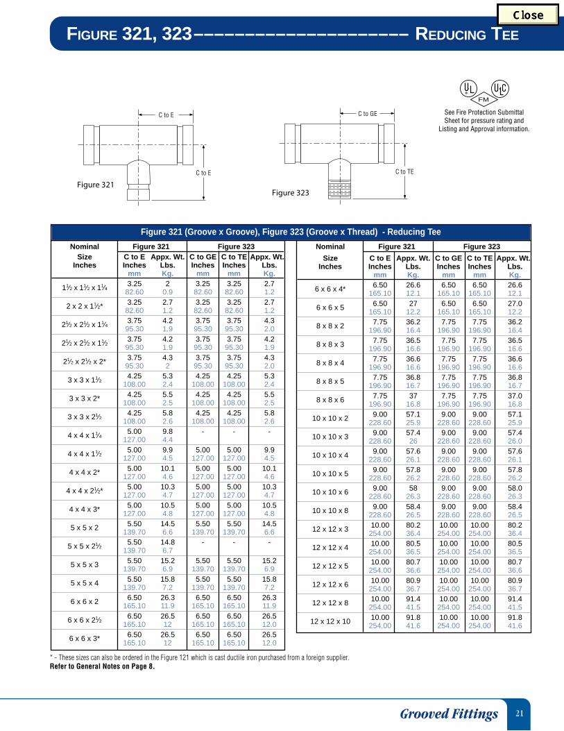
Figure 323
* - These sizes can also be ordered in the Figure 121 which is cast ductile iron purchased from a foreign supplier.Refer to General Notes on Page 8.
C to E
C to E
FIGURE 321, 323––––––––––––––––––––– REDUCING TEE
Figure 321
Nominal Figure 321 Figure 323Size C to E Appx. Wt. C to GE C to TE Appx. Wt.
Inches Inches Lbs. Inches Inches Lbs.mm Kg. mm mm Kg.
11⁄2 x 11⁄2 x 11⁄4 3.25 2 3.25 3.25 2.782.60 0.9 82.60 82.60 1.2
2 x 2 x 11⁄2* 3.25 2.7 3.25 3.25 2.782.60 1.2 82.60 82.60 1.2
21⁄2 x 21⁄2 x 11⁄4 3.75 4.2 3.75 3.75 4.395.30 1.9 95.30 95.30 2.0
21⁄2 x 21⁄2 x 11⁄2 3.75 4.2 3.75 3.75 4.295.30 1.9 95.30 95.30 1.9
21⁄2 x 21⁄2 x 2* 3.75 4.3 3.75 3.75 4.395.30 2 95.30 95.30 2.0
3 x 3 x 11⁄2 4.25 5.3 4.25 4.25 5.3108.00 2.4 108.00 108.00 2.4
3 x 3 x 2* 4.25 5.5 4.25 4.25 5.5108.00 2.5 108.00 108.00 2.5
3 x 3 x 21⁄2 4.25 5.8 4.25 4.25 5.8108.00 2.6 108.00 108.00 2.6
4 x 4 x 11⁄4 5.00 9.8 - - -127.00 4.4
4 x 4 x 11⁄2 5.00 9.9 5.00 5.00 9.9127.00 4.5 127.00 127.00 4.5
4 x 4 x 2* 5.00 10.1 5.00 5.00 10.1127.00 4.6 127.00 127.00 4.6
4 x 4 x 21⁄2* 5.00 10.3 5.00 5.00 10.3127.00 4.7 127.00 127.00 4.7
4 x 4 x 3* 5.00 10.5 5.00 5.00 10.5127.00 4.8 127.00 127.00 4.8
5 x 5 x 2 5.50 14.5 5.50 5.50 14.5139.70 6.6 139.70 139.70 6.6
5 x 5 x 21⁄2 5.50 14.8 - - -139.70 6.7
5 x 5 x 3 5.50 15.2 5.50 5.50 15.2139.70 6.9 139.70 139.70 6.9
5 x 5 x 4 5.50 15.8 5.50 5.50 15.8139.70 7.2 139.70 139.70 7.2
6 x 6 x 2 6.50 26.3 6.50 6.50 26.3165.10 11.9 165.10 165.10 11.9
6 x 6 x 21⁄2 6.50 26.5 6.50 6.50 26.5165.10 12 165.10 165.10 12.0
6 x 6 x 3* 6.50 26.5 6.50 6.50 26.5165.10 12 165.10 165.10 12.0
Nominal Figure 321 Figure 323
Size C to E Appx. Wt. C to GE C to TE Appx. Wt.Inches Inches Lbs. Inches Inches Lbs.
mm Kg. mm mm Kg.
6 x 6 x 4* 6.50 26.6 6.50 6.50 26.6165.10 12.1 165.10 165.10 12.1
6 x 6 x 5 6.50 27 6.50 6.50 27.0165.10 12.2 165.10 165.10 12.2
8 x 8 x 2 7.75 36.2 7.75 7.75 36.2196.90 16.4 196.90 196.90 16.4
8 x 8 x 3 7.75 36.5 7.75 7.75 36.5196.90 16.6 196.90 196.90 16.6
8 x 8 x 4 7.75 36.6 7.75 7.75 36.6196.90 16.6 196.90 196.90 16.6
8 x 8 x 5 7.75 36.8 7.75 7.75 36.8196.90 16.7 196.90 196.90 16.7
8 x 8 x 6 7.75 37 7.75 7.75 37.0196.90 16.8 196.90 196.90 16.8
10 x 10 x 2 9.00 57.1 9.00 9.00 57.1228.60 25.9 228.60 228.60 25.9
10 x 10 x 3 9.00 57.4 9.00 9.00 57.4228.60 26 228.60 228.60 26.0
10 x 10 x 4 9.00 57.6 9.00 9.00 57.6228.60 26.1 228.60 228.60 26.1
10 x 10 x 5 9.00 57.8 9.00 9.00 57.8228.60 26.2 228.60 228.60 26.2
10 x 10 x 6 9.00 58 9.00 9.00 58.0228.60 26.3 228.60 228.60 26.3
10 x 10 x 8 9.00 58.4 9.00 9.00 58.4228.60 26.5 228.60 228.60 26.5
12 x 12 x 3 10.00 80.2 10.00 10.00 80.2254.00 36.4 254.00 254.00 36.4
12 x 12 x 4 10.00 80.5 10.00 10.00 80.5254.00 36.5 254.00 254.00 36.5
12 x 12 x 5 10.00 80.7 10.00 10.00 80.7254.00 36.6 254.00 254.00 36.6
12 x 12 x 6 10.00 80.9 10.00 10.00 80.9254.00 36.7 254.00 254.00 36.7
12 x 12 x 8 10.00 91.4 10.00 10.00 91.4254.00 41.5 254.00 254.00 41.5
12 x 12 x 10 10.00 91.8 10.00 10.00 91.8254.00 41.6 254.00 254.00 41.6
Figure 321 (Groove x Groove), Figure 323 (Groove x Thread) - Reducing Tee
Grooved Fittings
FM
See Fire Protection Submittal Sheet for pressure rating and
Listing and Approval information.

22
Nominal E to E Appx. Wt.Size Inches Lbs.
Inches mm Kg.
11/4 4.00 0.8101.6 0.4
11/2 4.00 0.9101.6 0.4
2 4.00 1.2101.6 0.5
21/24.00 1.9101.6 0.9
3 4.00 2.5101.6 1.1
4 6.00 5.5152.4 2.5
Nominal E to E Appx. Wt.Size Inches Lbs.
Inches mm Kg.
5 6.00 7.4152.4 3.4
6 6.00 9.5152.4 4.3
8 6.00 14.2152.4 6.4
10 8.00 27.0203.2 12.2
12 8.00 33.0203.2 15.0
Figure 350Sizes 11⁄2” to 6”
Groove x Groove
Figure 372Groove x Thread
* These sizes can also be ordered in the Figure 150 Grooved Concentric Reducerwhich is cast ductile iron purchased from a foreign supplier.
Refer to General Notes on Page 8.
Grooved Fittings
REDUCERS & NIPPLES –––– FIGURE 301, 302, 303, 350, 372
Nominal E to E Appx. Wt.Size Inches Lbs.
Inches mm Kg.
11/2 x 11/42.50 0.663.5 0.3
2 x 11/42.50 0.863.5 0.4
2 x 11/22.50 0.863.5 0.4
21/2 x 11/42.50 1.063.5 0.5
21/2 x 11/22.50 1.363.5 0.6
21/2 x 2* 2.50 1.263.5 0.5
3 x 11/42.50 1.363.5 0.6
3 x 11/22.50 1.363.5 0.6
3 x 2* 2.50 1.363.5 0.6
3 x 21/2* 2.50 1.563.5 0.7
4 x 11/43.00 2.276.2 1.0
4 x 11/23.00 2.376.2 1.0
4 x 2* 3.00 2.376.2 1.0
4 x 21/2* 3.00 2.376.2 1.0
4 x 3* 3.00 2.676.2 1.2
5 x 11/23.50 4.688.9 2.1
5 x 2 3.50 4.688.9 2.1
5 x 21/23.50 4.588.9 2.0
5 x 3 3.50 4.488.9 2.0
5 x 4* 3.50 4.588.9 2.0
Nominal E to E Appx. Wt.Size Inches Lbs.
Inches mm Kg. 6 x 2* 4.00 6.0
101.6 2.7
6 x 21/24.00 6.0101.6 2.7
6 x 3* 4.00 6.0101.6 2.7
6 x 4* 4.00 5.9101.6 2.7
6 x 5* 4.00 5.8101.6 2.6
8 x 2 5.00 12.2127.0 5.5
8 x 21/25.00 12.1127.0 5.5
8 x 3 5.00 12.0127.0 5.5
8 x 4* 5.00 11.9127.0 5.4
8 x 5 5.00 11.3127.0 5.1
8 x 6* 5.00 10.8127.0 4.9
10 x 4 6.00 21.9152.4 10.0
10 x 5 6.00 21.6152.4 9.8
10 x 6* 6.00 21.1152.4 9.6
10 x 8* 6.00 19.5152.4 8.9
12 x 4 7.00 28.0177.8 12.7
12 x 6 7.00 30.0177.8 13.6
12 x 8* 7.00 28.0177.8 12.7
12 x 10* 7.00 33.0177.8 15.0
Figure 372
Concentric ReducerNominal E to E Appx. Wt.
Size Inches Lbs.Inches mm Kg.
11/2 x 1 2.50 0.663.5 0.3
2 x 3/42.50 1.063.5 0.5
2 x 1 2.50 0.863.5 0.4
2 x 11/42.50 0.863.5 0.4
2 x 11/22.50 0.863.5 0.4
21/2 x 11/42.50 1.063.5 0.5
21/2 x 11/22.50 1.363.5 0.6
21/2 x 2 2.50 1.263.5 0.5
3 x 1 2.50 1.363.5 0.6
3 x 11/22.50 1.363.5 0.6
3 x 2 2.50 1.363.5 0.6
3 x 21/22.50 1.563.5 0.7
31/2 x 3 2.50 1.563.5 0.7
4 x 11/23.00 2.376.2 1.0
4 x 2 3.00 2.376.2 1.0
4 x 21/23.00 2.376.2 1.0
4 x 3 3.00 2.676.2 1.2
5 x 4 3.50 4.588.9 2.0
6 x 2 4.00 6.0101.6 2.7
6 x 3 4.00 6.0101.6 2.7
6 x 4 4.00 5.9101.6 2.7
6 x 5 4.00 5.8101.6 2.6
Figure 350Sizes 8” to 24”
Groove x Groove
E to E
E to E
E to EFigure 350 - Concentric Reducer
E to E
E to EE to E
Figure 301
Figure 302Figure 303
Figure 301, 302, 303 -Adapter Nipples
FM
See Fire Protection Submittal Sheet for pressure rating and
Listing and Approval information.
23
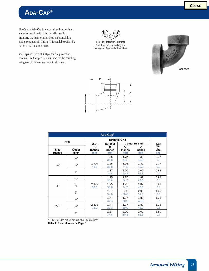
ADA-CAP®
The Central Ada-Cap is a grooved end cap with anelbow formed into it. It is typically used forinstalling the last sprinkler head on branch linepiping or as a drain fitting. It is available with 1⁄2",3⁄4", or 1" N.P.T outlet sizes.
Ada-Caps are rated at 300 psi for fire protectionsystems. See the specific data sheet for the couplingbeing used to determine the actual rating.
* BSP threaded outlets are available upon requestRefer to General Notes on Page 8.
FM
See Fire Protection Submittal Sheet for pressure rating and
Listing and Approval information.
BC
A
D
Grooved Fitting
Ada-Cap®
DIMENSIONSPIPE
O.D. Takeout Center to End NetA B C D Wt.
Size Outlet Inches Inches Inches Inches Lbs.Inches NPT* mm mm mm mm Kg.
1⁄2" 1.25 1.75 1.89 0.7731.8 44.5 48.0 0.3
11⁄2" 3⁄4" 1.900 1.25 1.75 1.89 0.7748.3 31.8 44.5 48.0 0.3
1" 1.37 2.00 2.02 0.8834.8 50.8 51.3 0.4
1⁄2" 1.25 1.75 1.89 0.9231.8 44.5 48.0 0.4
2" 3⁄4" 2.375 1.25 1.75 1.89 0.9260.3 31.8 44.5 48.0 0.4
1" 1.37 2.00 2.02 1.0634.8 50.8 51.3 0.5
1⁄2" 1.47 1.97 1.89 1.2837.3 50.0 48.0 0.6
21⁄2" 3⁄4" 2.875 1.47 1.97 1.89 1.2873.0 37.3 50.0 48.0 0.6
1" 1.37 2.00 2.02 1.5034.8 50.8 51.3 0.7
Patented
24
Supervisory TamperSwitch Circuits(Valve Fully Open)
Switch Rating10A 125, 250 VAC0.25A 250 VDC0.50A 125 VDC
Fire AlarmControl PanelSupervisory
Circuit
End of LineResistance
Or, Next Device
VoltageSource
CHASSIS
S1
S2NC
NOCOM
NC BLK
BLK/ORN
RED/ORN
RED
WHT
NOCOM
Utilization and Connection ofAuxiliary Switch to be Reviewed
and Approved by the LocalAuthority Having Jurisdiction
* Contact Tyco Fire Products for availabilty.Refer to General Notes on Page 8.
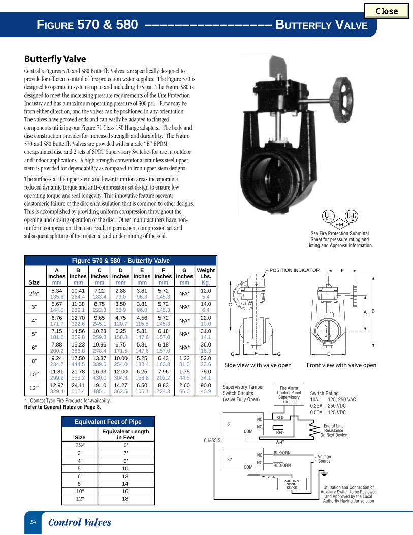
Central's Figures 570 and 580 Butterfly Valves are specifically designed toprovide for efficient control of fire protection water supplies. The Figure 570 isdesigned to operate in systems up to and including 175 psi. The Figure 580 isdesigned to meet the increasing pressure requirements of the Fire ProtectionIndustry and has a maximum operating pressure of 300 psi. Flow may befrom either direction, and the valves can be positioned in any orientation.The valves have grooved ends and can easily be adapted to flangedcomponents utilizing our Figure 71 Class 150 flange adapters. The body anddisc construction provides for increased strength and durability. The Figure570 and 580 Butterfly Valves are provided with a grade “E” EPDMencapsulated disc and 2 sets of SPDT Supervisory Switches for use in outdoorand indoor applications. A high strength conventional stainless steel upperstem is provided for dependability as compared to iron upper stem designs.
The surfaces at the upper stem and lower trunnion areas incorporate areduced dynamic torque and anti-compression set design to ensure lowoperating torque and seal longevity. This innovative feature preventselastomeric failure of the disc encapsulation that is common to other designs.This is accomplished by providing uniform compression throughout theopening and closing operation of the disc. Other manufacturers have non-uniform compression, that can result in permanent compression set andsubsequent splitting of the material and undermining of the seal.
Front view with valve open
FM
See Fire Protection Submittal Sheet for pressure rating and
Listing and Approval information.
Butterfly Valve
FIGURE 570 & 580 ––––––––––––––––– BUTTERFLY VALVE
Control Valves
Side view with valve open
E GG
C
POSITION INDICATOR F
D
A B
Figure 570 & 580 - Butterfly ValveA B C D E F G Weight
Inches Inches Inches Inches Inches Inches Inches Lbs.Size mm mm mm mm mm mm mm Kg.
21⁄2" 5.34 10.41 7.22 2.88 3.81 5.72 N⁄A* 12.0135.6 264.4 183.4 73.0 96.8 145.3 5.4
3" 5.67 11.38 8.75 3.50 3.81 5.72 N⁄A* 14.0144.0 289.1 222.3 88.9 96.8 145.3 6.4
4" 6.76 12.70 9.65 4.75 4.56 5.72 N⁄A* 22.0171.7 322.6 245.1 120.7 115.8 145.3 10.0
5" 7.15 14.56 10.23 6.25 5.81 6.18 N⁄A* 31.0181.6 369.8 259.8 158.8 147.6 157.0 14.1
6" 7.88 15.23 10.96 6.75 5.81 6.18 N⁄A* 36.0200.2 386.8 278.4 171.5 147.6 157.0 16.3
8" 9.24 17.50 13.37 10.00 5.25 6.43 1.22 52.0234.7 444.5 339.6 254.0 133.4 163.3 31.0 23.6
10"* 11.81 21.78 16.93 12.00 6.25 7.96 1.75 75.0299.9 553.2 430.0 304.3 158.8 202.2 44.5 34.1
12"* 12.97 24.11 19.10 14.27 6.50 8.83 2.60 90.0329.4 612.4 485.1 362.5 165.1 224.3 66.0 40.9
Equivalent Feet of PipeEquivalent Length
Size in Feet21⁄2" 6'
3" 7'
4" 6'5" 10'6" 13'8" 14'
10" 16'12" 18'

25
Grooved End Check Valve
All Figure 590F Check Valves have been designed with a removable cover for ease offield maintenance. They can be installed either horizontally or vertically in systemwith flow in either the upward or downward direction. The maximum workingpressure is 300 psi (2068 KPa). The standard seal is Grade “E” EPDM.
Applications: Figure 590F Check Valves are general purpose valves intended for usein fire protection systems as follows:1. From public water supplies to automatic sprinkler or standpipe systems.2. From fire department pumper connections to automatic sprinkler
or standpipe systems.3. In fire pump discharge or bypass piping.4. From gravity, suction, or pressure tanks to automatic sprinkler systems.
B
CHECK
A
J1/2" NPT
EF
D
1/2" NPT
C
VALVE
Refer to General Notes on Page 8.
FM
See Fire Protection Submittal Sheet for pressure rating and
Listing and Approval information.
Check Valve
CHECK VALVES ––––––––––––––––––––––– FIGURE 590F
Figure 590F - Check ValvesA B C D E F J Net Wt.
Size Inches Inches Inches Inches Inches Inches Inches Lbs.Inches mm mm mm mm mm mm mm Kg.
21⁄2" 8.00 5.80 3.41 3.40 3.88 6.00 1.70 10.0203.2 147.3 86.6 86.4 98.6 152.4 43.2 4.5
3" 8.37 5.76 3.60 3.40 3.88 6.00 1.70 11.0212.6 146.3 91.4 86.4 98.6 152.4 43.2 5.0
4" 9.63 6.74 4.61 3.63 4.53 7.13 1.84 25.0244.6 171.2 117.1 92.2 115.1 181.1 46.7 11.3
5" 10.50 7.50 5.29 4.20 4.90 7.60 1.90 29.0266.7 190.5 134.4 106.7 124.5 193.0 48.3 13.2
6" 11.50 8.05 5.75 4.50 5.00 7.60 1.48 47.0292.1 204.5 146.1 114.3 127.0 193.0 37.6 21.3
8" 14.00 10.25 7.75 5.62 5.45 8.40 2.20 66.0355.6 260.4 196.9 142.7 138.4 213.4 55.9 29.9
26
OUT OFSERVICE
TAG
MAINTENANCECAP, GASKETAND BOLTS
DANGER
OUT OFSERVICE
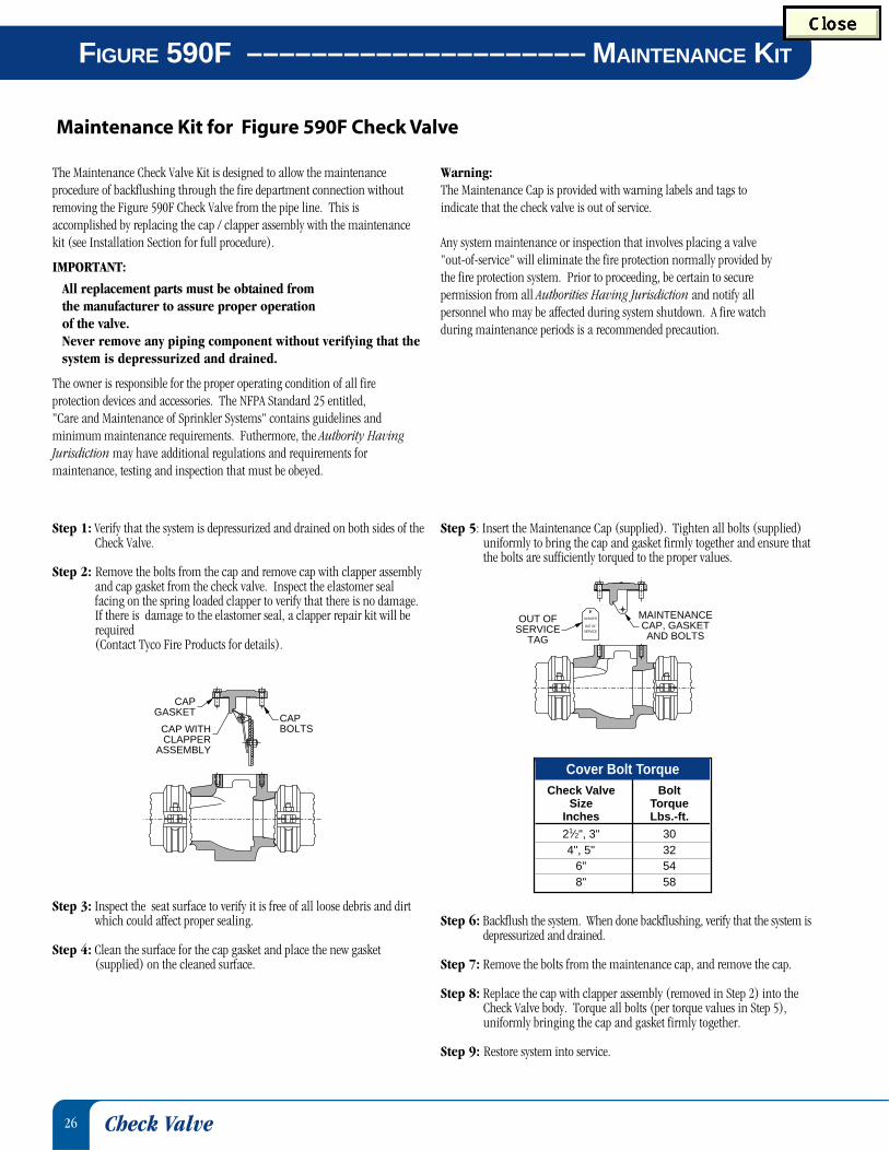
Maintenance Kit for Figure 590F Check Valve
Step 1: Verify that the system is depressurized and drained on both sides of theCheck Valve.
Step 2: Remove the bolts from the cap and remove cap with clapper assemblyand cap gasket from the check valve. Inspect the elastomer sealfacing on the spring loaded clapper to verify that there is no damage.If there is damage to the elastomer seal, a clapper repair kit will berequired(Contact Tyco Fire Products for details).
Step 3: Inspect the seat surface to verify it is free of all loose debris and dirtwhich could affect proper sealing.
Step 4: Clean the surface for the cap gasket and place the new gasket(supplied) on the cleaned surface.
CAPBOLTS
CAPGASKET
CAP WITHCLAPPER
ASSEMBLY
The Maintenance Check Valve Kit is designed to allow the maintenanceprocedure of backflushing through the fire department connection withoutremoving the Figure 590F Check Valve from the pipe line. This isaccomplished by replacing the cap / clapper assembly with the maintenancekit (see Installation Section for full procedure).
IMPORTANT:
All replacement parts must be obtained fromthe manufacturer to assure proper operationof the valve.Never remove any piping component without verifying that thesystem is depressurized and drained.
The owner is responsible for the proper operating condition of all fireprotection devices and accessories. The NFPA Standard 25 entitled,"Care and Maintenance of Sprinkler Systems" contains guidelines andminimum maintenance requirements. Futhermore, the Authority HavingJurisdiction may have additional regulations and requirements formaintenance, testing and inspection that must be obeyed.
Check Valve
FIGURE 590F ––––––––––––––––––––– MAINTENANCE KIT
Cover Bolt TorqueCheck Valve Bolt
Size TorqueInches Lbs.-ft.
21⁄2", 3" 304", 5" 32
6" 548" 58
Warning:The Maintenance Cap is provided with warning labels and tags toindicate that the check valve is out of service.
Any system maintenance or inspection that involves placing a valve"out-of-service" will eliminate the fire protection normally provided bythe fire protection system. Prior to proceeding, be certain to securepermission from all Authorities Having Jurisdiction and notify allpersonnel who may be affected during system shutdown. A fire watchduring maintenance periods is a recommended precaution.
Step 5: Insert the Maintenance Cap (supplied). Tighten all bolts (supplied)uniformly to bring the cap and gasket firmly together and ensure thatthe bolts are sufficiently torqued to the proper values.
Step 6: Backflush the system. When done backflushing, verify that the system isdepressurized and drained.
Step 7: Remove the bolts from the maintenance cap, and remove the cap.
Step 8: Replace the cap with clapper assembly (removed in Step 2) into theCheck Valve body. Torque all bolts (per torque values in Step 5),uniformly bringing the cap and gasket firmly together.
Step 9: Restore system into service.

27
Central
Central
Supply
System
GaugeSide
Main D
rain
B
D
Gauge
Main Drain
Side
A
C
Central Figure 590FR Fire Protection Riser Check Valves are furnished withgrooved ends and can be installed using Central grooved couplings. TheFigure 590FR can be installed with ANSI class 150 Flanges utilizing our Figure71 flange adapters and also ANSI class 300 Flange Adapters on the upstreamconnection. Should flanged connections be used on the downstreamconnection, longer 1⁄4" gauge nipple connections are required for clearance.All Figure 590FR Check Valves have been designed with a removable cover forease of field maintenance. They may be installed in either horizontal orvertical piping systems. The maximum working pressure is 300 psi (2068KPa). The standard seal is Grade “E” EPDM.
Applications: Figure 590FR Riser Check Valves are intended for use in wettype automatic sprinkler system risers, as a more attractive and economicalalternative to an alarm check valve. Provision must be made for a local alarmusing an approved flow switch (not included).
Grooved End Riser Check Valve
Refer to General Notes on Page 8.Note: Trim kit is sold seperately, unassembled.
FM
See Fire Protection Submittal Sheet for pressure rating and
Listing and Approval information.
Check Valve
RISER (CHECK VALVE) –––––––––––––––– FIGURE 590FR
4", 5", 6" & 8"RISER CHECK VALVE
Main Drain2" X 21⁄2" Nipple2" M X F Ball Valve2" 90° Elbow
Gauge (system side)0-300 psi Gauge1⁄4" X 2" Nipple1⁄4" Three-Way Globe
Valve1⁄4" Plug
Gauge (supply side)0-300 psi Gauge1⁄4" X 5" Nipple1⁄4" Three-Way Globe
21⁄2" & 3"RISER CHECK VALVE
Main Drain11⁄4" X 21⁄2" Nipple11⁄4" M X F Ball Valve11⁄4" 90° Elbow
Gauge (system side)0-300 psi Gauge1⁄4" X 2" Nipple1⁄4" Three-Way Globe
Valve1⁄4" Plug
Gauge (supply side)0-300 psi Gauge1⁄4" X 5" Nipple1⁄4" Three-Way Globe
Figure 590FR - Riser (Check Valve)Cover Bolt Net
A B C D Torque Wt.Size Inches Inches Inches Inches Lbs.-ft. Lbs.
Inches mm mm mm mm Nm Kg.
21⁄2" 8.00 12.53 3.88 13.20 30 10.0203.2 318.3 98.6 335.3 41 4.5
3" 8.37 13.02 3.88 13.65 30 11.0212.6 330.7 98.6 346.7 41 5.0
4" 9.63 14.38 4.96 15.38 32 25.0244.6 365.3 126.0 390.7 43 11.3
5" 10.50 14.95 4.96 15.95 32 29.0266.7 379.7 126.0 405.1 43 13.2
6" 11.50 15.25 4.98 16.25 54 47.0292.1 387.4 126.5 412.8 73 21.3
8" 14.00 16.37 5.48 17.37 58 66.0355.6 415.8 139.2 441.2 74 29.9
Trim Kits

28
FIGURE 513, 513D/513R––––––––––––––RISER MANIFOLD
The Figure 513, 513D/513R Riser Manifold provides all of the accessoryequipment for a riser in a single assembly. The availability of the RiserManifold in different configurations allows cost effective riser installations incommercial (NFPA 13) systems, high rise buildings requiring floor controlassemblies, and residential systems (NFPA 13D/13R).
The threaded ends of the 1" and 11⁄2" bodies, the threaded by grooved ends ofthe 2" bodies, and the grooved ends of the 11⁄2" - 6" bodies allow for an easytransition to either check or control valves. The exclusive and dedicated flowswitch designed for the manifolds has been tested and Listed for use in thisspecific configuration by Underwriters Laboratories, Underwriters Laboratoriesof Canada and Factory Mutual.
Installation is simplified with one convenient take-out for the 1" and 11/2"threaded and 11/2" grooved versions, as well as one take-out for the 2" threadedby grooved and the grooved sizes 2" - 6".
The Riser Manifold is approved for installation in either the horizontal or thevertical position. The optional relief valve assembly is available for locationsthat require this feature.
Riser Manifolds for use in Canada are provided with a Water Flow Switch thathas a Tamper Switch mounted inside for cover removal detection.
Refer to general notes on page 8.
Figure 513D
1" Threaded Residential Riser Manifold
Fire Protection
FM
See Fire Protection Submittal Sheet for pressure rating and
Listing and Approval information.
*Approximate thread engagement.Note: Values shown in parenthesis are in millimeters
Approximate Trimmed Weight - 7.5 lbs. (3.4Kg.)
The width of the Riser Manifold is approximately 31⁄2".
Note: Items 7 & 8 are used on Manifoldsfor use in Canada Only
175 PS
I
GA
UG
E
* .38[9.7]
8
2
7
3
6
5
4
1 * .63 [16]BOTH ENDS
10.00[254]
3.63[92.2]
2.88[73.2]
9.75 [247.7]
4.50[114.3]
ANDDRAIN
TEST
FLOW
CE
NT
RA
L
1"/33.4MM
1" Threaded Residential Riser ManifoldDetail PartNo. Description Number
1 Manifold Body F x F 976-363-01
2 Potter Waterflow Switch # VSR-SF w/Paddle H-416-01
3 1⁄4" Water Pressure Gauge 971-118-02
4 3⁄4" 90° Street Elbow H-463-075
5 3⁄4" Close Nipple H-474-12
6 3⁄4" Ball Valve 971-116-02
7 Tamper Switch (ULC only) H-419-01
8 Label (ULC only) 976-343-01
29
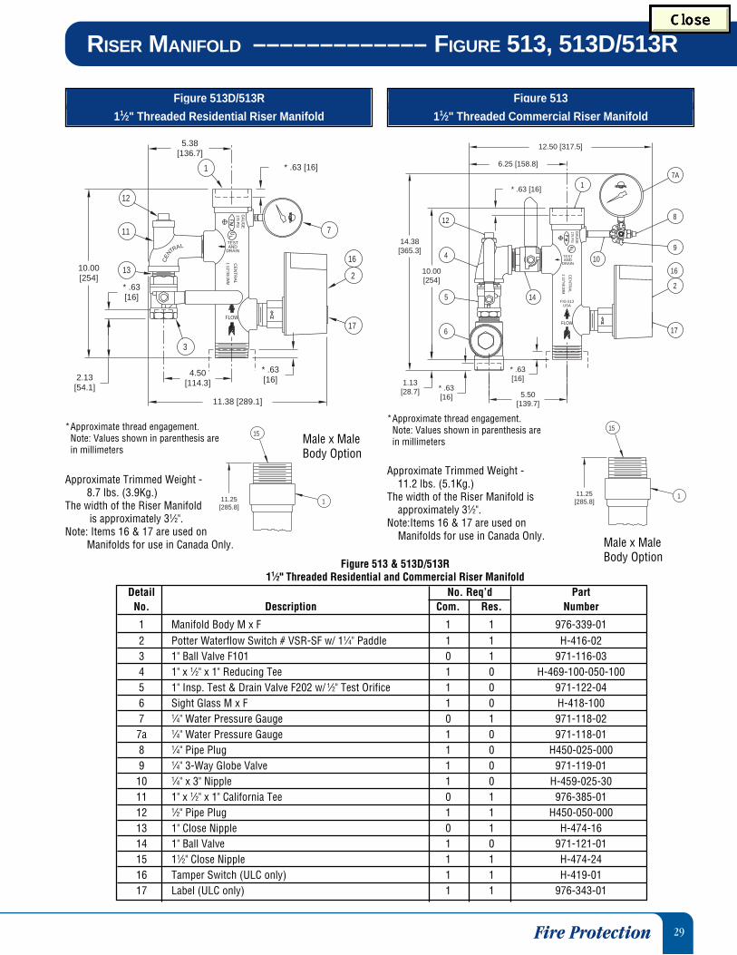
RISER MANIFOLD ––––––––––––– FIGURE 513, 513D/513R
Figure 513D/513R
11⁄2" Threaded Residential Riser Manifold
Fire Protection
Figure 513
11⁄2" Threaded Commercial Riser Manifold
175 PSIG
AU
GE
10
* .63[16]
6
7A
9
8
14.38[365.3]
145
12
4
1
* .63[16]
10.00[254]
6.25 [158.8]
* .63 [16]
16
17
12.50 [317.5]
2
1.13[28.7] 5.50
[139.7]
FLOW
USAFIG 513
TESTAND
DRAIN
1 1/2"/48.3MM
CE
NT
RA
L
Detail No. Req’d PartNo. Description Com. Res. Number
1 Manifold Body M x F 1 1 976-339-012 Potter Waterflow Switch # VSR-SF w/ 11⁄4" Paddle 1 1 H-416-023 1" Ball Valve F101 0 1 971-116-034 1" x 1⁄2" x 1" Reducing Tee 1 0 H-469-100-050-1005 1" Insp. Test & Drain Valve F202 w/ 1⁄2" Test Orifice 1 0 971-122-046 Sight Glass M x F 1 0 H-418-1007 1⁄4" Water Pressure Gauge 0 1 971-118-027a 1⁄4" Water Pressure Gauge 1 0 971-118-018 1⁄4" Pipe Plug 1 0 H450-025-0009 1⁄4" 3-Way Globe Valve 1 0 971-119-01
10 1⁄4" x 3" Nipple 1 0 H-459-025-3011 1" x 1⁄2" x 1" California Tee 0 1 976-385-0112 1⁄2" Pipe Plug 1 1 H450-050-00013 1" Close Nipple 0 1 H-474-1614 1" Ball Valve 1 0 971-121-0115 11⁄2" Close Nipple 1 1 H-474-2416 Tamper Switch (ULC only) 1 1 H-419-0117 Label (ULC only) 1 1 976-343-01
Male x MaleBody Option
11.25[285.8]
1
15
Approximate Trimmed Weight -11.2 lbs. (5.1Kg.)
The width of the Riser Manifold isapproximately 31⁄2".
Note:Items 16 & 17 are used onManifolds for use in Canada Only.
*Approximate thread engagement.Note: Values shown in parenthesis arein millimeters
Approximate Trimmed Weight -8.7 lbs. (3.9Kg.)
The width of the Riser Manifold is approximately 31⁄2".
Note: Items 16 & 17 are used onManifolds for use in Canada Only.
*Approximate thread engagement.Note: Values shown in parenthesis arein millimeters
11.25[285.8]
1
15
175 PSI
* .63[16]
3
* .63[16]
4.50[114.3]
* .63 [16]
2.13[54.1]
13
12
11
1
5.38[136.7]
10.00[254]
7
16
2
17
11.38 [289.1]
LARTNE
C
FLOW
TESTAND
DRAIN
GA
UG
E
1 1/2"/48.3MM
CE
NT
RA
L
Male x MaleBody Option
Figure 513 & 513D/513R11⁄2" Threaded Residential and Commercial Riser Manifold
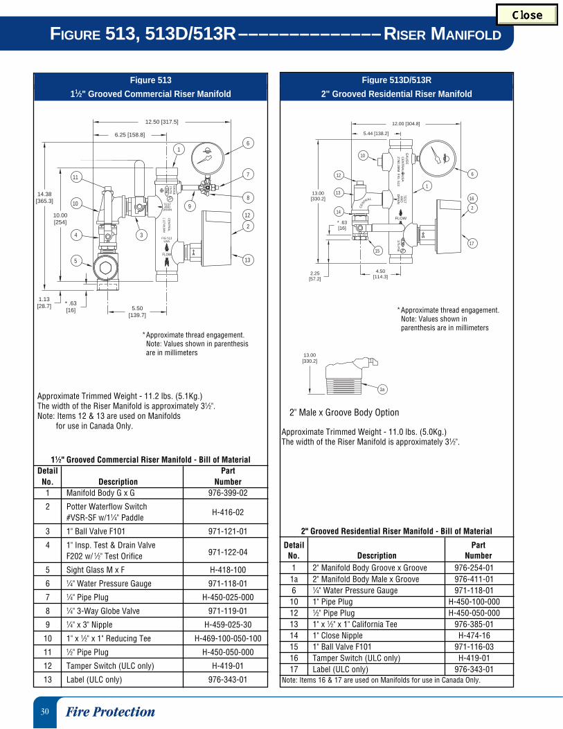
30
FIGURE 513, 513D/513R––––––––––––––RISER MANIFOLD
Fire Protection
Figure 513D/513R
2" Grooved Residential Riser Manifold
Figure 513
11⁄2" Grooved Commercial Riser Manifold
Approximate Trimmed Weight - 11.2 lbs. (5.1Kg.)The width of the Riser Manifold is approximately 31⁄2".Note: Items 12 & 13 are used on Manifolds
for use in Canada Only.
*Approximate thread engagement.Note: Values shown in parenthesisare in millimeters
175 PSIG
AU
GE
98
7
3
1
6.25 [158.8]
6
5.50[139.7]
11
10
4
5
* .63[16]
1.13[28.7]
10.00[254]
14.38[365.3]
12
2
13
12.50 [317.5]
FLOW
USAFIG 513
TESTAND
DRAIN
1 1/2"/48.3MM
CE
NT
RA
L
11⁄2" Grooved Commercial Riser Manifold - Bill of MaterialDetail Part
No. Description Number1 Manifold Body G x G 976-399-02
2 Potter Waterflow Switch#VSR-SF w/11⁄4" Paddle
H-416-02
3 1" Ball Valve F101 971-121-01
4 1" Insp. Test & Drain ValveF202 w/ 1⁄2" Test Orifice 971-122-04
5 Sight Glass M x F H-418-100
6 1⁄4" Water Pressure Gauge 971-118-01
7 1⁄4" Pipe Plug H-450-025-000
8 1⁄4" 3-Way Globe Valve 971-119-01
9 1⁄4" x 3" Nipple H-459-025-30
10 1" x 1⁄2" x 1" Reducing Tee H-469-100-050-100
11 1⁄2" Pipe Plug H-450-050-000
12 Tamper Switch (ULC only) H-419-01
13 Label (ULC only) 976-343-01
*Approximate thread engagement.Note: Values shown inparenthesis are in millimeters
2" Male x Groove Body Option
Approximate Trimmed Weight - 11.0 lbs. (5.0Kg.)The width of the Riser Manifold is approximately 31⁄2".
175 PS
I
6
2
17
16
1
15
10
12
13
14
13.00[330.2]
2.25[57.2]
* .63[16]
12.00 [304.8]
5.44 [138.2]
4.50[114.3]
GA
UG
EC
EN
TR
AL U
SA
2"/60.3MM
FIG
. 513A
ND
DR
AIN
TE
ST
FLOW
LRA
NE
C
T
1a
13.00[330.2]
Note: Items 16 & 17 are used on Manifolds for use in Canada Only.
2" Grooved Residential Riser Manifold - Bill of Material
Detail PartNo. Description Number1 2" Manifold Body Groove x Groove 976-254-011a 2" Manifold Body Male x Groove 976-411-016 1⁄4" Water Pressure Gauge 971-118-01
10 1" Pipe Plug H-450-100-00012 1⁄2" Pipe Plug H-450-050-00013 1" x 1⁄2" x 1" California Tee 976-385-0114 1" Close Nipple H-474-1615 1" Ball Valve F101 971-116-0316 Tamper Switch (ULC only) H-419-0117 Label (ULC only) 976-343-01

31
Figure 513
2", 21/2", 3", 4" and 6" Grooved Commercial Riser Manifold
RISER MANIFOLD ––––––––––––– FIGURE 513, 513D/513R
* Approximate thread engagement.** 13" is the take-out for all sizes 2"
through 6"Note: Values shown in parenthesis are
in millimeters
Approximate Weights and Dimensions of Trimmed2", 21/2", 3", 4", and 6" Grooved Commercial Riser Manifolds
A B C D Appx. Width WeightInches Inches Inches Inches Inches Lbs.mm mm mm mm mm Kg.
17.13 0.88 12.88 5.25 3.50 13.5135.0 22.2 327.0 139.7 88.9 6.118.13 1.88 13.75 6.38 3.50 16.8460.4 47.6 349.3 155.6 88.9 7.618.13 1.88 14.38 6.25 3.50 18.7460.4 47.6 365.1 158.8 88.9 8.520.00 3.75 17.38 8.38 4.50 32.7508.0 95.3 441.3 212.7 114.3 14.820.00 3.75 19.25 9.25 6.63 41.6508.0 95.3 489.0 235.0 182.3 18.9
SizeInches
2
21/2
3
4
6
175 PS
I
* .63 [16]
6
98
711
12
4
5
A
3
10
1
B
D
**13.00[330.2]
5.50 [139.7]
16
17
C
2
GA
UG
ET
ES
T
DR
AIN
AN
DC
EN
TR
AL U
SA
XX
X/X
XX
MM
FIG. 513
FLOW
Note: Items 16 & 17 are used onManifolds for use in Canada Only.
2", 21/2", 3", 4", & 6" Grooved Commercial Riser Manifold - Bill of Material
Detail PartNo. Description Number
2" Manifold Body Groove x Groove 976-254-0121⁄2" Manifold Body Groove x Groove 976-254-02
1 3" Manifold Body Groove x Groove 976-254-034" Manifold Body Groove x Groove 976-254-046" Manifold Body Groove x Groove 976-254-05
1a 2" Manifold Body Male x Groove 976-411-01Potter Waterflow Switch # VSC w/ 2" Paddle 976-357-01Potter Waterflow Switch # VSC w/ 21⁄2" Paddle 976-357-02
2 Potter Waterflow Switch # VSC w/ 3" Paddle 976-357-03Potter Waterflow Switch # VSC w/ 4" Paddle 976-357-04Potter Waterflow Switch # VSC w/ 6" Paddle 976-357-051" Ball Valve F101 (2") 971-121-01
3 11⁄4" Ball Valve F101 (21⁄2" and 3") 971-121-022" Ball Valve F101 (4" and 6") 971-121-031" Insp. Test & Drain Valve F202 (2") w/ 1⁄2" Test Orifice 971-122-04
4 11⁄4" Insp. Test & Drain Valve F202 (21⁄2" and 3") w/ 1⁄2" Test Orifice 971-122-052" Insp. Test & Drain Valve F202 (4" and 6") w/ 1⁄2" Test Orifice 971-122-061" Sight Glass (2") H-418-100
5 11⁄4" Sight Glass (21⁄2" and 3") H-418-1252" Sight Glass (4" and 6") H-418-200
6 1⁄4" Water Pressure Gauge 971-118-017 1⁄4" Pipe Plug H-450-025-0008 1⁄4" 3-Way Globe Valve 971-119-019 1⁄4" x 3" Nipple H-459-025-30
10 1" Pipe Plug H-450-100-0001" x 1⁄2" x 1" Reducing Tee (2") H-469-100-050-100
11 11⁄4" x 1⁄2" x 11⁄4" Reducing Tee (21⁄2" and 3") H-469-125-050-1252" x 1⁄2" x 2" Reducing Tee (4" and 6") H-469-200-050-200
12 1⁄2" Pipe Plug H-450-050-00013 1" x 1⁄2" x 1" California Tee 976-385-0114 1" Close Nipple H-474-1615 1" Ball Valve F101 971-116-0316 Tamper Switch (ULC only) H-419-0117 Label (ULC only) 976-343-01

32
Tri-Seal Freezer Gasket
The Tri-Seal Grade E freezer gasket is used primarily for dry pipe fireprotection systems, vacuum service, and freezer applications. The Tri-Sealfreezer gasket differs from standard gaskets by closing off the gap orgasket cavity. This is accomplished by positioning the center “rib” of thegasket over the gap between the pipes. The Tri-Seal freezer gasket has twotapered sealing edges in addition to the center rib for additional strengthand sealing.
The Tri-Seal freezer gasket is available in sizes 11⁄4" to 12" and is designedfor use with Central Figure 572 and 772 Couplings. A petroleum-freesilicone based lubricant is recommended for dry pipe systems. For lowtemperature services or dry systems in cold storage or freezer applications,use Tri-Seal freezer gaskets. For vacuum services greater than 10" Hg,Tri-Seal gaskets should be used.
Note: Rigid couplings figures 572 and 772 are preferred for vacuum, drypipe and freezer applications.
Technical Data
GASKETS
LubeTM
Pre-Lube Gasket - Patent Pending
Prelubricated gaskets are provided with aproprietary coating which eliminates the needfor the installer to apply a lubricant duringthe assembly process.
• Grade A EPDMA violet color codeambient to +150°F (+66°C) for fireprotection systems. Not recommendedfor hot water systems.
Note: For dry pipe and freezer applications, use the Tri-Seal FreezerGasket with a petroleum free silicone lubricant.Refer to General notes on Page 8.
Gaskets
Temp. ColorGrade Range Compound Code General Sevice Application
Ambient Fire Protection Systems. Notto Recommended for Hot Water
A +150°F EPDMA Violet Systems. For dry pipe or(+66°C) freezer systems, use Tri-Seal
Grade E Gasket
-30°F(-34°C) Fire Protection Systems. For
E to EPDM Green dry pipe or freezer systems use+230°F Tri-Seal grade E Gasket.
(+110°C)

33
Roll Groove
1) The maximum allowable tolerances for IPS pipefrom square cut ends is 0.030" (0.76mm) forsizes 11⁄4"- 3"; 0.045" (1.14mm) for sizes4"-6"; and 0.060" (1.52mm) for sizes 8"and above.
2) Gasket Seating Surface "A" must be free fromscore marks, ridges, indentations, projections,loose paint, scale, dirt chips, grease, rust, etc.
TB
D
COD
A
Groove Specifications
ROLL GROOVE SPECIFICATIONS
3) Groove diameter "C" must be of uniform deptharound the circumference of the pipe.
4) Groove Depth "D" is a reference dimension only.The Groove Diameter "C" must be maintained.
5) Minimum Wall Thickness "T" is the minimumwall thickness that should be roll grooved.
6) Maximum allowable pipe end flare diameter ismeasured at the pipe end diameter.
Roll Groove SpecificationsPipe O.D. A B C D T Maximum
Inches ± 0.030" ± 0.030" Groove Diameter Groove Minimum Allow. FlareNom mm ±0.76mm ±0.76mm Inches Depth Wall DiameterPipe Tolerance Inches Inches mm Inches Inches InchesSize O.D. + - mm mm Actual Tol.+0.00 mm mm mm
11/4" 1.660 0.016 0.016 0.625 0.281 1.535 -0.015 0.062 0.065 1.7742.2 0.41 0.41 15.88 7.14 38.99 -0.38 1.60 1.65 44.96
11/2" 1.900 0.019 0.019 0.625 0.281 1.775 -0.015 0.062 0.065 2.0148.3 0.48 0.48 15.88 7.14 45.09 -0.38 1.60 1.65 51.05
2" 2.375 0.024 0.024 0.625 0.344 2.250 -0.015 0.062 0.065 2.4860.3 0.61 0.61 15.88 8.74 57.15 -0.38 1.60 1.65 62.99
21/2" 2.875 0.029 0.029 0.625 0.344 2.720 -0.018 0.078 0.083 2.9873.0 0.74 0.74 15.88 8.74 69.09 -0.46 1.98 2.11 75.69
76.1mm3.000 0.030 0.030 0.625 0.344 2.845 -0.018 0.076 0.083 3.1076.1 0.76 0.76 15.88 8.74 72.26 -0.46 1.93 2.11 78.74
3" 3.500 0.035 0.031 0.625 0.344 3.344 -0.018 0.078 0.083 3.6088.9 0.89 0.79 15.88 8.74 84.94 -0.46 1.98 2.11 91.44
4" 4.500 0.045 0.031 0.625 0.344 4.334 -0.020 0.083 0.083 4.60114.3 1.14 0.79 15.88 8.74 110.08 -0.51 2.11 2.11 116.84
5" 5.563 0.056 0.031 0.625 0.344 5.395 -0.022 0.084 0.109 5.66141.3 1.42 0.79 15.88 8.74 137.03 -0.56 2.13 2.77 143.76
165.1mm6.500 0.063 0.031 0.625 0.344 6.330 -0.022 0.085 0.109 6.60165.1 1.60 0.79 15.88 8.74 160.78 -0.56 2.16 2.77 167.64
6" 6.625 0.063 0.031 0.625 0.344 6.455 -0.022 0.085 0.109 6.73168.3 1.60 0.79 15.88 8.74 163.96 -0.56 2.16 2.77 170.94
8" 8.625 0.063 0.031 0.750 0.469 8.441 -0.025 0.092 0.109 8.80219.1 1.60 0.79 19.05 11.91 214.40 -0.64 2.34 2.77 223.52
10" 10.750 0.063 0.031 0.750 0.469 10.562 -0.027 0.094 0.134 10.92273.1 1.60 0.79 19.05 11.91 268.27 -0.69 2.39 3.40 277.37
12" 12.750 0.063 0.031 0.750 0.469 12.531 -0.030 0.109 0.156 12.92323.9 1.60 0.79 19.05 11.91 318.29 -0.76 2.77 3.96 328.17
34 Terms & Conditions
ORDER PROCEDURE, CARE & MAINTENANCE, LIMITED WARRANTY
Ordering Procedure Ordering Information: When placing an order, indicate the full product name.Please specify the quantity, figure number and size.
Availability and Service: Grooved Piping Products, valves, accessories and otherproducts are available throughout the U.S., Canada, and internationally, through anetwork of distribution centers. You may write directly or call 215-362-0700 for thedistributor nearest you.
Care and Maintenance The owner is responsible for the inspection, testing, and maintenance of their fire protectionsystem and devices in accordance with the applicable standards of the National FireProtection Association (e.g., NFPA 25), in addition to the standards of any authority havingjurisdiction. The installing contractor or product manufacturer should be contacted relativeto any questions. Any impairment must be immediately corrected.
It is recommended that automatic sprinkler systems be inspected, tested, and maintainedby a qualified Inspection Service.
Limited Warranty Products manufactured by Tyco Fire Products are warranted solely to the original Buyer forten (10) years against defects in material and workmanship when paid for and properlyinstalled and maintained under normal use and service. This warranty will expire ten (10)years from date of shipment by Tyco Fire Products. No warranty is given for products orcomponents manufactured by companies not affiliated by ownership with Tyco FireProducts or for products and components which have been subject to misuse, improperinstallation, corrosion, or which have not been installed, maintained, modified or repaired inaccordance with applicable Standards of the National Fire Protection Association (NFPA),and/or the standards of any other Authorities Having Jurisdiction. Materials found by TycoFire Products to be defective shall be either repaired or replaced, at Tyco Fire Products’sole option. Tyco Fire Products neither assumes, nor authorizes any person to assume forit, any other obligation in connection with the sale of products or parts of products. TycoFire Products shall not be responsible for sprinkler system design errors or inaccurate orincomplete information supplied by Buyer or Buyer’s representatives.
IN NO EVENT SHALL TYCO FIRE PRODUCTS BE LIABLE, IN CONTRACT, TORT,STRICT LIABILITY OR UNDER ANY OTHER LEGAL THEORY, FOR INCIDENTAL,INDIRECT, SPECIAL OR CONSEQUENTIAL DAMAGES, INCLUDING BUT NOT LIMITEDTO LABOR CHARGES, REGARDLESS OF WHETHER TYCO FIRE PRODUCTS WASINFORMED ABOUT THE POSSIBILITY OF SUCH DAMAGES, AND IN NO EVENTSHALL TYCO FIRE PRODUCTS’ LIABILITY EXCEED AN AMOUNT EQUAL TO THESALES PRICE.
THE FOREGOING WARRANTY IS MADE IN LIEU OF ANY AND ALL OTHERWARRANTIES EXPRESS OR IMPLIED, INCLUDING WARRANTIES OFMERCHANTABILITY AND FITNESS FOR A PARTICULAR PURPOSE.
Governing Law These terms and conditions of sale shall be construed under and in accordance with thelaws of the Commonwealth of Pennsylvania. Buyer consents and agrees to the jurisdic-tion and venue of the Court of Common Pleas of Montgomery County, Pennsylvania andthe U.S. District Court for the Eastern District of Pennsylvania with respect to any proceed-ing arising out of or in connection with any transaction entered into between Central andBuyer. Buyer further agrees that mailing to either party by certified registered mail shallconstitute lawful and valid service of process.

FEATURES• Anti Rotation Flexible (575) and Rigid (572) Couplings• 300 psi Rated Fire Protection Working Pressures• Pre-Lube and Standard Gaskets• Available in Painted and Galvanized Coatings• Strong Technical Support• Available World-Wide
• Guarantee Customer Satisfaction
CENTRAL GROOVED PRODUCTSWe Design It, We Make It, We Guarantee It!
For more information callTFP Distribution 800-558-5236 or Central Sprinkler Company at 800-523-6512
visit our website at www.tyco-fire.com
Tyco Fire ProductsHEADQUARTERS451 North Cannon AvenueLansdale, PA 19446Phone: (215) 362-0700
(800) 523-6512Fax: (215) 362-5385www.tyco-fire.com
CENTRALGROOVED PIPING PRODUCTSTechnical and Engineering Services1467 Elmwood Ave.Cranston, RI 02910Phone: (401) 781-8220
(800) 381-9312Fax: (800) 791-5500
DISTRIBUTED BY
Printed in USA / RPI / CGPPFP / 4.02 / 10M / ©Tyco Fire Products 2002Printed in USA / RPI / CGPPFP / 4.02 / 10M / ©Tyco Fire Products 2002
Tyco Fire ProductsHEADQUARTERS451 North Cannon AvenueLansdale, PA 19446Phone: (215) 362-0700
(800) 523-6512Fax: (215) 362-5385 www.tyco-fire.com
CENTRALGROOVED PIPING PRODUCTSTechnical and Engineering Services1467 Elmwood Ave.Cranston, RI 02910Phone: (401) 781-8220
(800) 381-9312Fax: (800) 791-5500
DISTRIBUTED BY