case-encapsulated triboelectric nanogenerator for ...case-encapsulated triboelectric nanogenerator...
TRANSCRIPT
JING ET AL. VOL. XXX ’ NO. XX ’ 000–000 ’ XXXX
www.acsnano.org
A
CXXXX American Chemical Society
Case-Encapsulated TriboelectricNanogenerator for Harvesting Energyfrom Reciprocating Sliding MotionQingshen Jing,†,‡,^Guang Zhu,†,^ Peng Bai,† Yannan Xie,† Jun Chen,† Ray P. S. Han,‡ and Zhong LinWang†,§,*
†School of Materials Science and Engineering, Georgia Institute of Technology, Atlanta, Georgia 30332-0245, United States, ‡College of Engineering,Peking University, Beijing 100871, China, and §Beijing Institute of Nanoenergy and Nanosystems, Chinese Academy of Sciences, Beijing 100083, China. ^Q. Jing andG. Zhu contributed equally.
Harnessing ambient mechanical en-ergy is attracting a lot of attentiondue to the fast development of
portable electronics and sensor networks.1,2
Mechanisms using piezoelectric,3�6 electro-static7,8 or electromagnetic9,10 principles toharvest energy from random vibrations,11
wind flow,12 air pressure,13 or human bodymotions14 have been developed andapplied as generators or self-poweredsensors.13,15 Recently, the development oftriboelectric nanogenerators (TENGs) offersa new paradigm for fabricating high-outputand cost-effective generators for drivingsmall electronics.16�19 Reciprocating mo-tion is a very common mechanical mo-tion that occurs in natural oscillations,motion of waves, swing of human limbs,and mechanical piston movements, etc.Features of these motions that include longreciprocating distance, low frequenciesand amplitude or frequency fluctua-tions pose challenges for previously devel-oped vibration-harvesters,11,20�23 whichwere only suited to low-amplitude and
high-frequency excitations induced by in-ertia forces.Here we report a compact case-encapsu-
lated triboelectric nanogenerator (cTENG) thattargets reciprocating motions driven by eitherdirect or inertia forces. The cTENG relies onelectrode pairs that have fine-grating patternson cylindrical sliding surfaces to generatealternating current. Operating at a sliding ve-locity of 1m/s over a slidingdistanceof 3.8 cm,a cTENG with an effective contact area of90 cm2 could generate an output charge of12.7μC in a single full slide,which correspondsto an average output DC current of as high as0.35 mA. At the matched load of 140 kΩ, anaverage output power of 12.2 mW wasachieved. We demonstrated the use of cTENGto harness oscillating motion from sourcessuch as human and water wave motions asan indication of its potential in portable self-powered electronics and power generation.
RESULTS AND DISCUSSION
The structural configurationof thecTENG isdepicted in Figure 1 by using two concentric
* Address correspondence [email protected].
Received for review February 4, 2014and accepted March 4, 2014.
Published online10.1021/nn500694y
ABSTRACT Reciprocating motion is a widely existing form of mechanical motion
in natural environment. In this work we reported a case-encapsulated triboelectric
nanogenerator (cTENG) based on sliding electrification to convert reciprocating
motion into electric energy. Patterned with multiple sets of grating electrodes and
lubricated with polytetrafluoroethylene (PTFE) nanoparticles, the cTENG exported an
average effective output power of 12.2 mW over 140 kΩ external load at a sliding
velocity of 1 m/s, in corresponding to a power density of 1.36 W/m2. The sliding
motion can be induced by direct-applied forces as well as inertia forces, enabling the
applicability of the cTENG in addressing ambient vibration motions that feature large
amplitude and low frequency. The cTENG was demonstrated to effectively harvest
energy from human body motions and wavy water surface, indicating promising
prospects of the cTENG in applications such as portable and stand-alone self-powered electronics.
KEYWORDS: reciprocating motion . energy harvesting . triboelectric nanogenerators . casing . self-powered
ARTIC
LE
JING ET AL. VOL. XXX ’ NO. XX ’ 000–000 ’ XXXX
www.acsnano.org
B
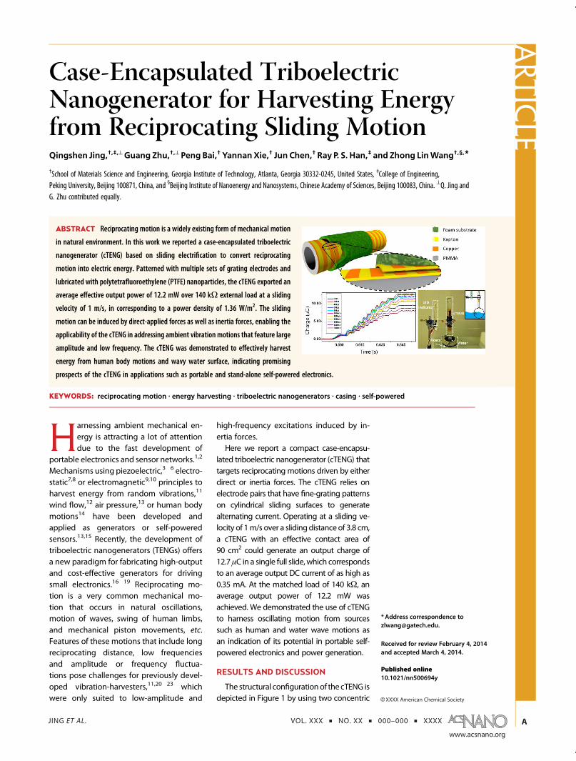
cylinders that can slide one against the other. The basicprinciple of the cTENG relies on sliding triboelectrifica-tion at the interface. The case wrap applied tightlyaround the outer cylinder allows the two cylindricalstructures to move in a coaxial 1-D motion relative toeach other. Polyimide film (Kapton) was selected asan electrification material for generating triboelectriccharges and also as the supporting substrate. TheKapton film was chosen as it possesses good electrifi-cation and tensile strength properties (see S1 fromSupporting Information (SI) for details), leading to ahigh-performance in electricity generation and dura-bility. On both sides of the Kapton film, copper stripes(width of 2 mm) were deposited with a linear pitch of4 mm. The electrode patterns on different sides ex-hibited a linear shift of half pitch so that they arecomplementary to each other (Figure 1b, 1c). TwoKapton films having the same electrode patternsformed a pair of contact surfaces (Figure 1b). All copperstripes on the two contact surfaces were connected bybus electrodes to form a common inner electrode (IE),while those on back surfaces of the Kapton filmsconstituted an outer electrode (OE) (Figure 1c). Spher-ical polytetrafluoroethylene (PTFE) nanoparticles werespread between the contact surfaces (Figure 1f) aslubricant to reduce friction and to further improveenergy conversion efficiency (see details in S2 from SI).The two prepared Kapton films with electrodes wereapplied on the outer surface of a PMMA tube and theinner surface of a foam tube, respectively (Figure 1d).The fully assembled cTENG is shown in Figure 1e.The electricity generation mechanism of the cTENG
is illustrated in Figure 2. The outer tube slides relative tothe inner tube, forming a reciprocating movement. Asworking mechanism of the cTENG, when Kapton and
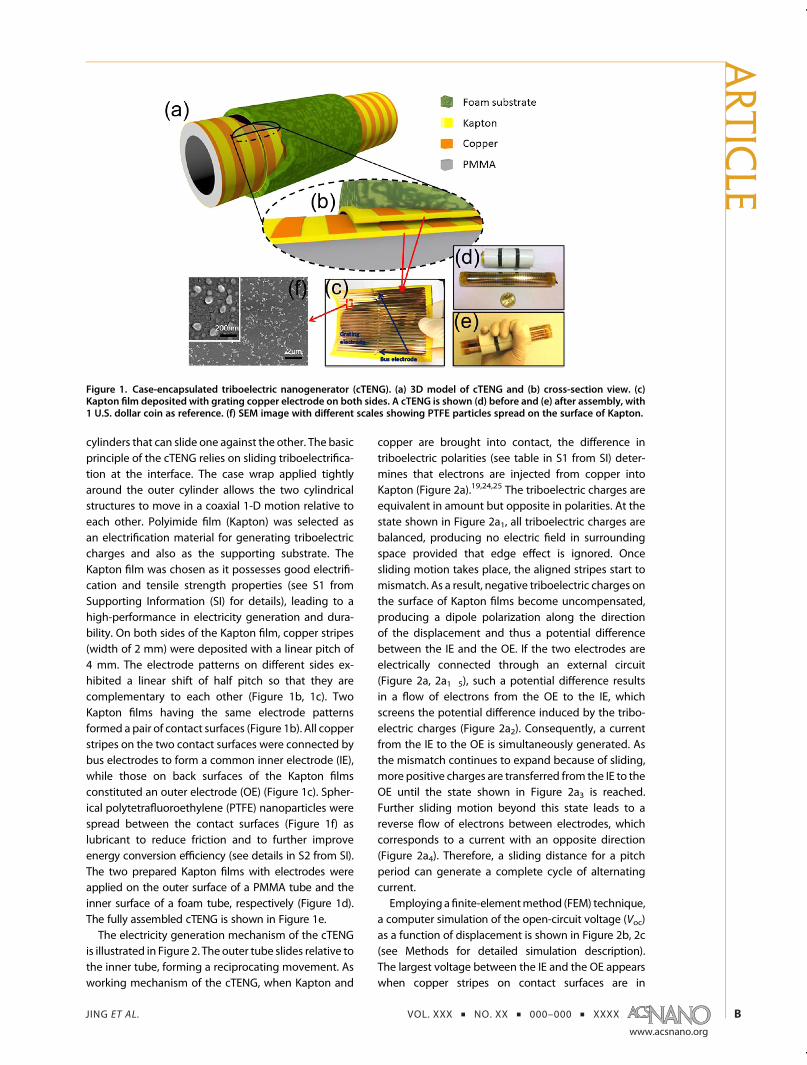
copper are brought into contact, the difference intriboelectric polarities (see table in S1 from SI) deter-mines that electrons are injected from copper intoKapton (Figure 2a).19,24,25 The triboelectric charges areequivalent in amount but opposite in polarities. At thestate shown in Figure 2a1, all triboelectric charges arebalanced, producing no electric field in surroundingspace provided that edge effect is ignored. Oncesliding motion takes place, the aligned stripes start tomismatch. As a result, negative triboelectric charges onthe surface of Kapton films become uncompensated,producing a dipole polarization along the directionof the displacement and thus a potential differencebetween the IE and the OE. If the two electrodes areelectrically connected through an external circuit(Figure 2a, 2a1�5), such a potential difference resultsin a flow of electrons from the OE to the IE, whichscreens the potential difference induced by the tribo-electric charges (Figure 2a2). Consequently, a currentfrom the IE to the OE is simultaneously generated. Asthe mismatch continues to expand because of sliding,more positive charges are transferred from the IE to theOE until the state shown in Figure 2a3 is reached.Further sliding motion beyond this state leads to areverse flow of electrons between electrodes, whichcorresponds to a current with an opposite direction(Figure 2a4). Therefore, a sliding distance for a pitchperiod can generate a complete cycle of alternatingcurrent.Employinga finite-elementmethod (FEM) technique,
a computer simulation of the open-circuit voltage (Voc)as a function of displacement is shown in Figure 2b, 2c(see Methods for detailed simulation description).The largest voltage between the IE and the OE appearswhen copper stripes on contact surfaces are in
Figure 1. Case-encapsulated triboelectric nanogenerator (cTENG). (a) 3D model of cTENG and (b) cross-section view. (c)Kapton film deposited with grating copper electrode on both sides. A cTENG is shown (d) before and (e) after assembly, with1 U.S. dollar coin as reference. (f) SEM image with different scales showing PTFE particles spread on the surface of Kapton.
ARTIC
LE
JING ET AL. VOL. XXX ’ NO. XX ’ 000–000 ’ XXXX
www.acsnano.org
C
complete alignment (Figure 2b1, 2b3, 2b5 and thecontinuous motion is shown in Video M1 from SI).Because of the mobility of electrons on copper, a smallmismatch from aligned position would result in severecharge redistribution, resulting in a sharp shaped Voccurve. The experimentally measured Voc is presented inFigure 2d, which has a resembling but slightly differentpattern compared to the simulated value in Figure 2c.This is probably due to minor off-alignment duringfabrication and measurement, which is discussed inS3 from SI. The FEM simulation also reveals the charge-transferring process between electrodes, as presentedin Figure 2e. Induced charges on one electrode exhibita triangle-shaped patternwith respect to displacement.Again, the experimentally obtained data (Figure 2f)based on a time-integration of the short-circuit currentIsc (details presented in S4 from SI) are in good agree-ment with the simulation result.To characterize the electric output of the cTENG, Isc
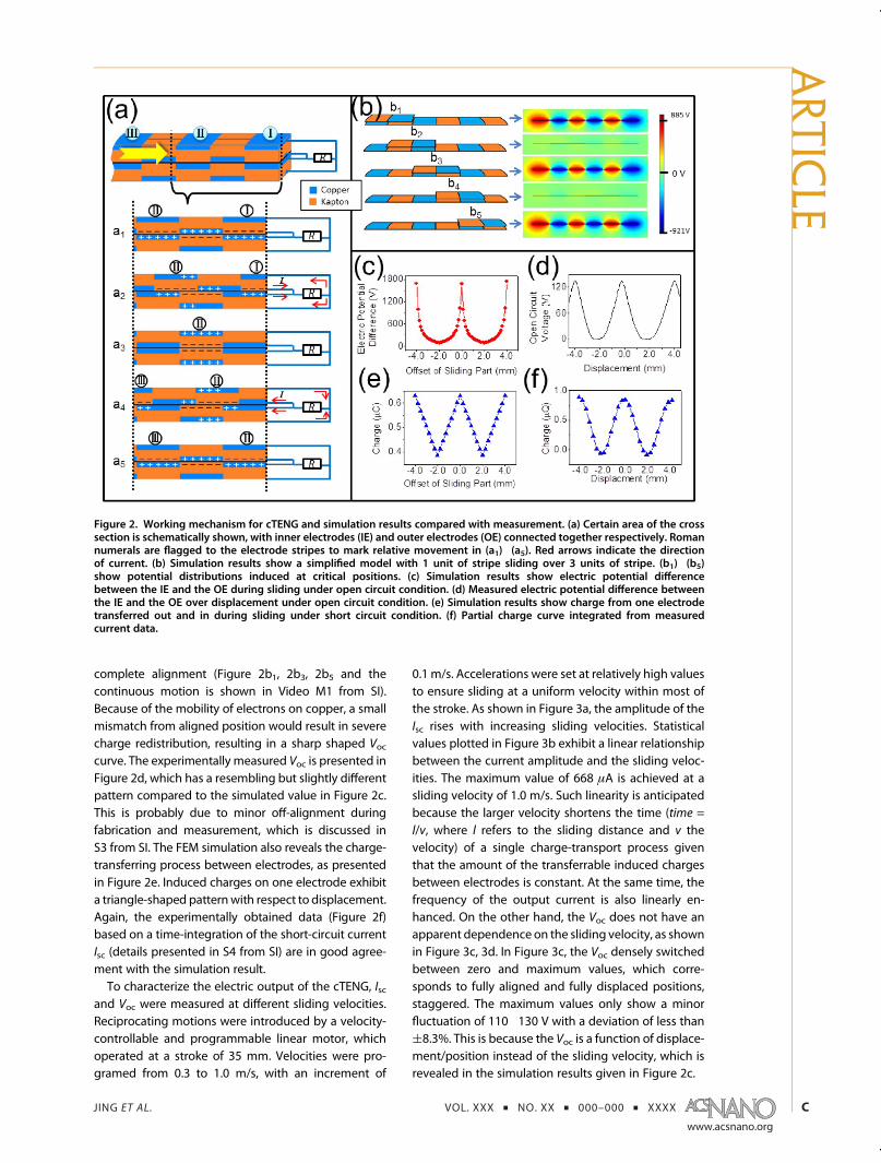
and Voc were measured at different sliding velocities.Reciprocating motions were introduced by a velocity-controllable and programmable linear motor, whichoperated at a stroke of 35 mm. Velocities were pro-gramed from 0.3 to 1.0 m/s, with an increment of
0.1 m/s. Accelerations were set at relatively high valuesto ensure sliding at a uniform velocity within most ofthe stroke. As shown in Figure 3a, the amplitude of theIsc rises with increasing sliding velocities. Statisticalvalues plotted in Figure 3b exhibit a linear relationshipbetween the current amplitude and the sliding veloc-ities. The maximum value of 668 μA is achieved at asliding velocity of 1.0 m/s. Such linearity is anticipatedbecause the larger velocity shortens the time (time =l/v, where l refers to the sliding distance and v thevelocity) of a single charge-transport process giventhat the amount of the transferrable induced chargesbetween electrodes is constant. At the same time, thefrequency of the output current is also linearly en-hanced. On the other hand, the Voc does not have anapparent dependence on the sliding velocity, as shownin Figure 3c, 3d. In Figure 3c, the Voc densely switchedbetween zero and maximum values, which corre-sponds to fully aligned and fully displaced positions,staggered. The maximum values only show a minorfluctuation of 110�130 V with a deviation of less than(8.3%. This is because the Voc is a function of displace-ment/position instead of the sliding velocity, which isrevealed in the simulation results given in Figure 2c.
Figure 2. Working mechanism for cTENG and simulation results compared with measurement. (a) Certain area of the crosssection is schematically shown, with inner electrodes (IE) and outer electrodes (OE) connected together respectively. Romannumerals are flagged to the electrode stripes to mark relative movement in (a1)�(a5). Red arrows indicate the directionof current. (b) Simulation results show a simplified model with 1 unit of stripe sliding over 3 units of stripe. (b1)�(b5)show potential distributions induced at critical positions. (c) Simulation results show electric potential differencebetween the IE and the OE during sliding under open circuit condition. (d) Measured electric potential difference betweenthe IE and the OE over displacement under open circuit condition. (e) Simulation results show charge from one electrodetransferred out and in during sliding under short circuit condition. (f) Partial charge curve integrated from measuredcurrent data.
ARTIC
LE
JING ET AL. VOL. XXX ’ NO. XX ’ 000–000 ’ XXXX
www.acsnano.org
D
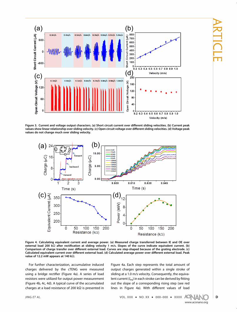
For further characterization, accumulative inducedcharges delivered by the cTENG were measuredusing a bridge rectifier (Figure 4a). A series of loadresistors were utilized for output power measurement(Figure 4b, 4c, 4d). A typical curve of the accumulatedcharges at a load resistance of 200 kΩ is presented in
Figure 4a. Each step represents the total amount ofoutput charges generated within a single stroke ofsliding at a 1.0 m/s velocity. Consequently, the equiva-lent current (Ieq) in each stroke can be derived by fittingout the slope of a corresponding rising step (see redlines in Figure 4a). With different values of load
Figure 3. Current and voltage output characters. (a) Short circuit current over different sliding velocities. (b) Current peakvalues show linear relationship over sliding velocity. (c) Open circuit voltage over different sliding velocities. (d) Voltage peakvalues do not change much over sliding velocity.
Figure 4. Calculating equivalent current and average power. (a) Measured charge transferred between IE and OE overexternal load 200 kΩ after rectification at sliding velocity 1 m/s. Slopes of the curve indicate equivalent current. (b)Comparison of charge transfer over different external load. Curves are step-shaped because of the grating electrode. (c)Calculated equivalent current over different external load. (d) Calculated average power over different external load. Peakvalue of 12.2 mW appears at 140 kΩ.
ARTIC
LE

JING ET AL. VOL. XXX ’ NO. XX ’ 000–000 ’ XXXX
www.acsnano.org
E
resistance, the equivalent current varies as shown inFigure 4c, in which larger load corresponds to lowerequivalent current. Detailed shape of accumulatedcharge curve in one complete sliding via external loadwith span from 0 to 200 kΩ was organized intoFigure 4b, in which several distinctive features can beobserved. With larger external load, the curves end atlower charge levels. For each individual curve, thestarting few steps and ending few steps show a smallerslope than the middle ones, meaning they are at lowerinstantaneous velocity because of the acceleration anddeceleration of the linearmotor. (One of the signs is theleveled part of the steps from the first and last arelonger than the others.) As the slope reflects equivalentcurrent, it is optimal to apply the cTENG on long strokeand large acceleration motions. The obtained equiva-lent current can be further used to calculate averageoutput power (Peq), which is equivalent to the Jouleheating of the external load and, thus, is defined asPeq = Ieq
2 � Rload. Figure 4d reveals the output poweras a function of the external load, which reaches amaximum value of 12.2 mW at a load of 140 kΩ, incorresponding to a power density of 1.36 W/m2.To demonstrate the power-generating ability of
cTENG, we apply the device to harvest energyfrom the wave motion of water and human motions.Reciprocating motions, including both periodical(vibration) and nonperiodical forms, widely exist indaily life. Examples include but are not limited toengine cylinders, damping systems, human body mo-tions, and water waves caused by wind, etc. In the firstdemonstration, cTENG was connected to a float andheld vertically over the water surface (Figure 5a, 5a1).
Whenwave fronts passed over the float, the fluctuationof thewater surface caused float tomove up anddown,triggering cTENG. Tens of green LEDs powered by thecTENG were lit up (Figure 5b, Video M2 (SI)). Such ademonstration shows potential applications of thecTENG in water (lake/river/marine) navigation fieldsfor self-powered buoy lights, channel lights, under-water obstructions warning lights, etc.The human body motion is another rich source of
energy that can be harvested. By simply shakingcTENG, a series of parallel connected white bulbs werelit up (Figure 5c, 5d, 5e, Video M3 (SI)). The cTENG canbe further attached to certain parts of the human body,such as hand, forearm, leg or even torso, with itsencapsulated casing designed in such a way to permitrelative motion in order to generate electricity duringhuman movements due to jogging, jumping, etc.
CONCLUSIONS
In summary, we demonstrated a novel style of TENGwith an encapsulated cylindrical case that not onlydelivers a high output but also has several uniquefeatures. Grating designed Kapton/copper surfacewith PTFE particle lubricant ensures a high efficientoutput. An output current equivalent to a DC source ofas high as 0.35 mA and an equivalent power 12.2 mW(corresponding power density 1.36 W/m2) wereachieved during a sliding velocity of 1.0 m/s. Theoutput increases with increasing velocities. Simula-tions to explain the working mechanism were offered,and detailed features of the charge transfer werestudied using FEM. For demonstration, a float-connected cTENG generated enough power to light
Figure 5. cTENG in applicationof harvesting reciprocating energy. (a) cTENGwas connected to afloat to harvestwave energy.Schematic diagram is in (a1). (b) Green LEDs were lit when artificial wave passed by. cTENG tested in human body motion.White bulbs were driven off�on�off (c) before, (d) during, and (e) after cTENG was shaken by hand.
ARTIC
LE
JING ET AL. VOL. XXX ’ NO. XX ’ 000–000 ’ XXXX
www.acsnano.org
F
upmultiple LEDbulbs driven by energy ofwaterwaves.The cTENG was also applied to harvesting energy from
human body motion. This work indicates cTENG as aneffective power converter for self-powered electronics.
METHODSFabrication of cTENG. Two pieces of Kapton film (25 μm thick)
with size 12 cm � 15 cm (longer one) and 12 cm � 7.5 cm(shorter one)were prepared and cleanedwith isopropyl alcohol.Two pieces of acrylic board (1.5 mm thick) with size 12 cm �15 cm (longer one) and 12 cm � 7.5 cm (shorter one) wereprepared by laser cutter. Hollow stripes with individual size0.2 cm � 12 cm were brought on such acrylic boards by a lasercutter, arranged parallel in a linear pitch of 4 mm, spread overthe available area of two boards. A perpendicular column acrossall the stripes at their middle point was also engraved. Thesepierced boards were used as masks for electrode deposition.Kapton films were covered with corresponding-sized acrylicmask on one side and were conducted with copper electrodedeposition by physical vapor deposition facilities for the firsttime. Then same masks were used for the other surface ofpretreated Kapton film with a linear shift of 2 mm beforeconducting with copper deposition. Acrylic cylinder rod withlength 15 cm and diameter 3.81 cm was coated with thin layerof polydimethylsiloxane (PDMS) on the surface and was thenwrapped with pretreated Kapton film (longer one) as inner part.PTFE particles (DuPont Teflon Non-Stick Dry-Film Lubricant)were spread onto the surface of this Kapton film. The otherpretreated Kapton film (shorter one) was then wrapped over(but not stuck to) the inner part, followed by another layerof 0.3 cm thickness double-sided foam tape. Polyethyleneterephthalate (PET) film with 75 μm thickness was finallyapplied onto the outer surface of the foam tape as a supportmaterial to complete the casing structure. The outer part wasable to move smoothly along the inner part in the mannerof piston form. Metal wires were connected to electrode fromeach surface of the two Kapton films, with electrodes locatedbetween contacting surface set as inner electrode (IE), on theback sides of Kapton films set as outer electrode (OE).
Finite Element Analysis Method. Software “Comsol Multiphysics4.2” was chosen for simulating the open circuit voltage.Model “Electrostatics” was chosen for simulating open-circuitvoltage and short-circuit charge transfer. A charge density of20 μC/m2 was applied on the Kapton surface as an equi-valent result of friction. To reduce the computing complexity,one unit of stripe sliding over 3 units of stripe was simulated.Simulation mainly focused on cross-section and was con-ducted in 2-dimensional model. To calculate charge, depth ofthe 2D model was set large enough to meet the actual workingarea. Width of electrodes and thickness of Kapton were as-signed with actual value. Relative permittivity of Kapton wasset as 3.4.
Conflict of Interest: The authors declare no competingfinancial interest.
Acknowledgment. Researchwas supportedby the “thousandstalents” program for pioneer researcher and his innovation team,China, Beijing City Committee of science and technology project(Z131100006013004). Chinese Scholarship Council financiallysupports Qingshen Jing in participating GT-PKU Joint Ph.D.Program during his study in the United States.
Supporting Information Available: (1) Triboelectric series(S1). (2) cTENG behavior influenced by PTFE nanoparticlelubricant (S2). (3) Voltage output affected by improper alignedelectrodes (S3). (4) Charge curve calculated from measuredcurrent data (S4). (5) Video for voltage output distribution fromsimulation results (M1). (6) Video of cTENG harvesting energyfrom wave motion (M2). (7) Video of cTENG harvesting energyfrom human body motion (M3). This material is available free ofcharge via the Internet at http://pubs.acs.org.
REFERENCES AND NOTES1. Dresselhaus, M. S.; Thomas, I. L. Alternative Energy Tech-
nologies. Nature 2001, 414, 332–337.2. Wang, Z. L. Self-Powered Nanosensors and Nanosystems.
Adv. Mater. 2012, 24, 280–285.3. Wang, X. D.; Song, J. H.; Liu, J.; Wang, Z. L. Direct-Current
Nanogenerator Driven by Ultrasonic Waves. Science 2007,316, 102–105.
4. Wang, Z. L.; Song, J. H. Piezoelectric Nanogenerators BasedonZincOxideNanowire Arrays. Science2006, 312, 242–246.
5. Xu, S.; Qin, Y.; Xu, C.; Wei, Y. G.; Yang, R. S.; Wang, Z. L. Self-Powered Nanowire Devices. Nat. Nanotechnol. 2010, 5,366–373.
6. Yang, R. S.; Qin, Y.; Dai, L. M.; Wang, Z. L. Power Generationwith Laterally Packaged Piezoelectric Fine Wires. Nat.Nanotechnol. 2009, 4, 34–39.
7. Mitcheson, P. D.; Miao, P.; Stark, B. H.; Yeatman, E. M.;Holmes, A. S.; Green, T. C. MEMS Electrostatic MicropowerGenerator for Low Frequency Operation. Sens. Actuators, A2004, 115, 523–529.
8. Pelrine, R.; Kornbluh, R.; Eckerle, J.; Jeuck, P.; Oh, S. J.; Pei,Q. B.; Stanford, S. Dielectric Elastomers: Generator ModeFundamentals and Applications. Proc. Soc. Photo-Opt.Instrum. Eng. 2001, 4329, 148–156.
9. Arnold, D. P. Review of Microscale Magnetic PowerGeneration. IEEE Trans. Magn. 2007, 43, 3940–3951.
10. Williams, C. B.; Shearwood, C.; Harradine,M. A.; Mellor, P. H.;Birch, T. S.; Yates, R. B. Development of an ElectromagneticMicro-generator. IEE Proceedings, Part G: Circuits, Devicesand Systems 2001, 148, 337–342.
11. Chen, J.; Zhu, G.; Yang, W. Q.; Jing, Q. S.; Bai, P.; Yang, Y.;Hou, T. C.; Wang, Z. L. Harmonic-Resonator-Based Tribo-electric Nanogenerator as a Sustainable Power Source anda Self-Powered Active Vibration Sensor. Adv. Mater. 2013,25, 6094–6099.
12. Zhang, R.; Lin, L.; Jing, Q. S.; Wu, W. Z.; Zhang, Y.; Jiao, Z. X.;Yan, L.; Han, R. P. S.; Wang, Z. L. Nanogenerator as an ActiveSensor for Vortex Capture and Ambient Wind-VelocityDetection. Energy Environ. Sci. 2012, 5, 8528–8533.
13. Hu, Y. F.; Xu, C.; Zhang, Y.; Lin, L.; Snyder, R. L.; Wang, Z. L.A Nanogenerator for Energy Harvesting from a RotatingTire and its Application as a Self-Powered Pressure/SpeedSensor. Adv. Mater. 2011, 23, 4068–4071.
14. Lee, M.; Chen, C. Y.; Wang, S.; Cha, S. N.; Park, Y. J.; Kim, J. M.;Chou, L. J.; Wang, Z. L. A Hybrid Piezoelectric Structure forWearable Nanogenerators. Adv. Mater. 2012, 24, 1759–1764.
15. Lee, M.; Bae, J.; Lee, J.; Lee, C. S.; Hong, S.; Wang, Z. L. Self-Powered Environmental Sensor System Driven by Nano-generators. Energy Environ. Sci. 2011, 4, 3359–3363.
16. Fan, F. R.; Lin, L.; Zhu, G.; Wu, W. Z.; Zhang, R.; Wang,Z. L. Transparent Triboelectric Nanogenerators and Self-PoweredPressure Sensors Based onMicropatterned PlasticFilms. Nano Lett. 2012, 12, 3109–3114.
17. Wang, S. H.; Lin, L.; Wang, Z. L. Nanoscale Triboelectric-Effect-Enabled Energy Conversion for Sustainably Power-ing Portable Electronics. Nano Lett. 2012, 12, 6339–6346.
18. Yang, Y.; Lin, L.; Zhang, Y.; Jing, Q. S.; Hou, T. C.; Wang, Z. L.Self-Powered Magnetic Sensor Based on a TriboelectricNanogenerator. ACS Nano 2012, 6, 10378–10383.
19. Wang, Z. L. Triboelectric Nanogenerators as New EnergyTechnology for Self-Powered Systems and as ActiveMechanical and Chemical Sensors. ACS Nano 2013, 7,9533–9557.
20. Leland, E. S.; Wright, P. K. Resonance Tuning of Piezo-electric Vibration Energy Scavenging Generators UsingCompressive Axial Preload. Smart Mater. Struct. 2006, 15,1413–1420.
ARTIC
LE
JING ET AL. VOL. XXX ’ NO. XX ’ 000–000 ’ XXXX
www.acsnano.org
G
21. Challa, V. R.; Prasad, M. G.; Shi, Y.; Fisher, F. T. A VibrationEnergy Harvesting Device with Bidirectional ResonanceFrequency Tunability. Smart Mater. Struct. 2008, 17,015035.
22. Beeby, S. P.; Torah, R. N.; Tudor, M. J.; Glynne-Jones, P.;O'Donnell, T.; Saha, C. R.; Roy, S. A Micro ElectromagneticGenerator for Vibration Energy Harvesting. J. Micromech.Microeng. 2007, 17, 1257–1265.
23. Hu, Y. F.; Yang, J.; Jing, Q. S.; Niu, S. M.; Wu, W. Z.; Wang, Z. L.Triboelectric Nanogenerator Built on Suspended 3D SpiralStructure as Vibration and Positioning Sensor and WaveEnergy Harvester. ACS Nano 2013, 7, 10424–10432.
24. Wang, S. H.; Lin, L.; Xie, Y. N.; Jing, Q. S.; Niu, S. M.; Wang, Z. L.Sliding-Triboelectric Nanogenerators Based on In-PlaneCharge-Separation Mechanism. Nano Lett. 2013, 13, 2226–2233.
25. Zhu, G.; Chen, J.; Liu, Y.; Bai, P.; Zhou, Y. S.; Jing, Q. S.; Pan,C. F.; Wang, Z. L. Linear-Grating Triboelectric GeneratorBased on Sliding Electrification. Nano Lett. 2013, 13, 2282–2289.
ARTIC
LE