carts 2010, new orleans, march 16, 2010 · carts 2010, new orleans, march 16, 2010 ... thin film...
TRANSCRIPT

CARTS 2010, New Orleans, March 16, 2010
CARTS USA 2010 PresentationCARTS USA 2010 PresentationLow Pass Filter Bandwidth Optimization to Generate
Electrical Duobinary Signal for 40 Gb/s OpticalElectrical Duobinary Signal for 40 Gb/s Optical System’s Duobinary Modulation Format
Akhlaq Rahman, Mark Broman, Mike Howieson
Thin Film Technology CorporationThin Film Technology CorporationNorth Mankato, Minnesota

Outline
Motivation R f D b d l f f F b Review of Duobinary modulation format for Fiber optics
communication system Low pass filter bandwidth analysis p f y Filter bandwidth optimization Low pass Bessel Thomson filter design D i f b i i Device fabrication Measured results Proof of concept Proof of concept Summary and conclusion Acknowledgement and Future work
CARTS 2010 LPF bandwidth optimization for duobinary modulation 2

Motivation
Today’s multimedia rich communication pushes the system data rate to be 40 Gbps (and 100 Gbps in near f t re)data rate to be 40 Gbps (and 100 Gbps in near future)
Components need to be upgraded to support higher data rate
For successful deployment of Duobinary modulation format, Bessel low pass filter’s bandwidth needs to be increased
Correct filter bandwidth improves the system performance
Filter bandwidth needs to be optimized for higher data rate
Research is done to realize the filter’s bandwidth for the best system performance
CARTS 2010 LPF bandwidth optimization for duobinary modulation 3

Review: Duobinary modulation format for Optical Communicationp
Optical duobinary transmission system enjoys higher system performance for optical communication systemp p y Higher spectral efficiency Has narrower spectrum bandwidthp Excellent tolerance for chromatic and residual dispersion Minimum channel spacing allowing DWDM capability
Optical duobinary modulation format operates as follows Binary signal is converted to three level electrical signal Three level signal (“-1”, “0”, and “+1”) drives the MZM Signal amplitude “-1” and “+1” becomes optical “1” and
CARTS 2010 LPF bandwidth optimization for duobinary modulation 4
amplitude “0” becomes optical “0”
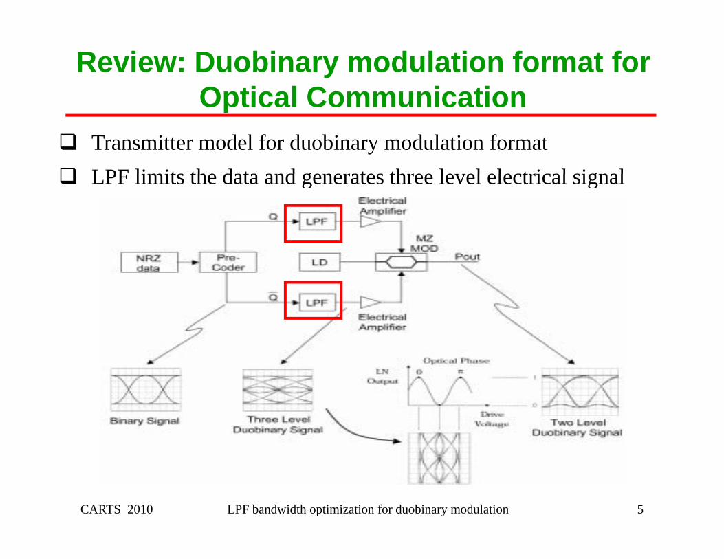
Review: Duobinary modulation format for Optical CommunicationOptical Communication
Transmitter model for duobinary modulation format LPF limits the data and generates three le el electrical signal LPF limits the data and generates three level electrical signal
CARTS 2010 LPF bandwidth optimization for duobinary modulation 5

Low Pass Filter Bandwidth Analysis
Three level signal amplitude depends on LPF’s bandwidth LPF bandwidth needs to be 0 25 to 0 33 of the signal data rate LPF bandwidth needs to be 0.25 to 0.33 of the signal data rate TFT’s 3.0 GHz Bessel filter provides excellent 3 level electrical
signal for 10 Gbps optical signalsignal for 10 Gbps optical signal
u.)
Eye diagram of 3 level electrical signal for 10 Gbps optical Duobinary signal
•Observable binary eye amplitude (A) is 45% of signal eyepl
itude
(a.u
45% of signal eye amplitude (B)
igna
l am
p
CARTS 2010 LPF bandwidth optimization for duobinary modulation 6
S
Time samples (a. u.)

Low Pass Filter Bandwidth Optimization
We simulated duobinary transmitter model for 40 Gbps data rate Used ideal Bessel low pass filter for generating three level
electrical signal Ch d fil b d id h f diff i l li d Changed filter bandwidth for different signal amplitude Used Bessel low pass filter having –3dB bandwidth from 8 GHz
t 15 GHto 15 GHz Observed electrical binary eye height to signal’s eye height By comparing the eye diagram we chose the filter that produced By comparing the eye diagram, we chose the filter that produced
three level eye diagram where binary eye height is closest to 45% of signal eye height
CARTS 2010 LPF bandwidth optimization for duobinary modulation 7
45% of signal eye height

Transmitter Model Simulation Result
•binary h i ht
•binary h i hteye height
is 11% of signal eye height
eye height is 17% of signal eye height
LPF BW = 8 GHz LPF BW = 9 GHz
•binary eye height is 26% of
•binary eye height is 39% of
LPF BW = 11 GHz
fsignal eye height
fsignal eye height
CARTS 2010 LPF bandwidth optimization for duobinary modulation 8
LPF BW = 10 GHz LPF BW = 11 GHz

Transmitter Model Simulation Result
•binary h i ht
•binary h i hteye height
is 46% of signal eye height
eye height is 54% of signal eye height
LPF BW = 12 GHz LPF BW = 13 GHz
•binary eye height is 59% of
•binary eye height is 69% of
LPF BW = 15 GHz
fsignal eye height
fsignal eye height
CARTS 2010 LPF bandwidth optimization for duobinary modulation 9
LPF BW = 14 GHz LPF BW = 15 GHz

Designed absorptive low pass filter
12 GHz Bessel low pass filter provided best three level eye diagram
Binary eye height is 46% of signal eye height Ob d ji i 1 44 Observed jitter is 1.44 ps Based on the result, we designed 12 GHz Bessel low pass filter F b tt t l h t i ti d i d b ti For better return loss characteristics we designed absorptive
Bessel low pass filter We designed 9th order absorptive filter to match characteristics We designed 9th order absorptive filter to match characteristics
of 5th order ideal Bessel filter
CARTS 2010 LPF bandwidth optimization for duobinary modulation 10

Designed absorptive low pass filter
Insertion Loss resultR t L ltReturn Loss result
CARTS 2010 LPF bandwidth optimization for duobinary modulation 11

Absorptive Low Pass Filter Fabrication
We fabricated the 12 GHz absorptive low pass Bessel filter Filter is fabricated in Al min m s bstrate ith 0 63 mm Filter is fabricated in Aluminum substrate with 0.63 mm
thickness Filter size is 2 0 mm X 7 2 mm in BGA package Filter size is 2.0 mm X 7.2 mm in BGA package
Top view of the filter Bottom view of the filter
CARTS 2010 LPF bandwidth optimization for duobinary modulation 12
p

Absorptive Low Pass Filter Fabrication
Filter is housed in evaluation board for measurement procedure E al ation board’s PCB material is Rogers 4350 10 mil thick Evaluation board’s PCB material is Rogers 4350, 10 mil thick,
½ oz. CU.
Evaluation board PCB Evaluation board with filter
CARTS 2010 LPF bandwidth optimization for duobinary modulation 13
va uat o boa d C va uat o boa d w t te

Measured results of fabricated LPF
Fabricated filter was measured Data as compared ith sim lation res lts Data was compared with simulation results
Insertion Loss results comparison Return Loss results comparison
CARTS 2010 LPF bandwidth optimization for duobinary modulation 14
Insertion Loss results comparison

Proof of Concept
We used measured data into the simulated transmitter model Three le el electrical signal is prod ced sing the model Three level electrical signal is produced using the model Data rate was 40 Gbps Eye diagram of the three level signal is observed Eye diagram of the three level signal is observed
)
Eye diagram of 3 level electrical signal using fabricated 12 GHz Bessel LPF
itude
(a.u
.)
•Observable binary eye
gnal
am
pli y y
amplitude is 42% of signal eye amplitude
CARTS 2010 LPF bandwidth optimization for duobinary modulation 15
Sig p

Proof of Concept Fabricated absorptive low pass filter was used in 40 Gbps
optical duobinary transmission systemp y y Eye diagram of 3 level electrical and 2 level optical duobinary
signal is as followg
(a.u
.)
(a.u
.)
ampl
itude
ampl
itude
Sign
al a
Sign
al a
CARTS 2010 LPF bandwidth optimization for duobinary modulation 16
Time samples (a. u.)Time samples (a. u.)

Summary and conclusion
We discussed influence of low pass filter’s bandwidth for d obinar mod lation formatduobinary modulation format
We analyzed LPF’s bandwidth for 10 Gbps system We simulated 40 Gbps duobinary transmitter model and used We simulated 40 Gbps duobinary transmitter model and used
LPF with different bandwidth We optimized LPF’s bandwidth for best three level signal’s eye We optimized LPF s bandwidth for best three level signal s eye
diagram Based on the simulation results we designed 12 GHz Based on the simulation results, we designed 12 GHz
absorptive Bessel Thomson LPF
CARTS 2010 LPF bandwidth optimization for duobinary modulation 17

Summary and conclusion
We fabricated 12 GHz absorptive Bessel Thomson LPF from simulation results
Measured data was compared to simulation result W d d l i d l d d h l l We used measured result in model and generated three level
eye diagram M d lt di l l t h i l ti Measured results eye diagram closely matches simulation
results eye diagram We presented some industry system performance result using We presented some industry system performance result using
our fabricated 12 GHz Bessel Thomson Low Pass Filter
CARTS 2010 LPF bandwidth optimization for duobinary modulation 18

Acknowledgement
We would like to thank Mr. Kano and Mr. Ryo Shimizu from Sumitomo Osaka Cement Company for sharing data of 10 Gbps duobinary system using our LPF
W ld lik h k D Mi h l Vi lli f U i i We would like to thank Dr. Michael Vitalli from University College London (UCL) for discussion on LPF and its b d idth i t f l d bi d l ti f tbandwidth impact on successful duobinary modulation format deployment
We would like to thank Mr Eric Darvin from Narda L3 We would like to thank Mr. Eric Darvin from Narda L3 Communication for sharing data of 40 Gbps duobinary system using our LPF also for various important discussion
CARTS 2010 LPF bandwidth optimization for duobinary modulation 19
using our LPF, also for various important discussion

Future Work
Future work can be done on Low pass filter for 100 Gbps Duobinary modulation format system
Low pass filter bandwidth can be optimized for receiver system
LPF’s impact can be studied for other advanced modulation f t (i DPSK DQPSK OOK)format (ie. DPSK, DQPSK, OOK)
Other electrical passive device can be studied for advanced modulation formatmodulation format
Thank you!CARTS 2010 LPF bandwidth optimization for duobinary modulation 20
Thank you!