cartridge valves technical information fan drive … drive hics 14.6 520l0588 • rev db •...
TRANSCRIPT

Fan
Dri
ve H
ICs
14.1520L0588 • Rev DB • November 2010
Cartridge Valves Technical InformationFan Drive HICs
Fan Drive HICs Model No. Cavity Description Flow* Pressure Page
P108 200E
TG
AA
B
PG
P
T
C
B
RFD-40-000 none Fan Drive HIC with
Reversing Control
Up to 40 l/min
[10.5 US gal/min]
See performance chart
210 bar
[3000 psi]
14.6
RFD-80-000 none Up to 80 l/min
[21.1 US gal/min]
See performance chart
210 bar
[3000 psi]
14.8
Fan Drive HICs Model No. Cavity Description Flow* Pressure Page
P108 198E
TG
D
AA
B
PG
P
T
D
C
B
RFD-40-PRV none Fan Drive HIC with
Proportional and
Reversing Control
Up to 40 l/min
[10.5 US gal/min]
See performance chart
210 bar
[3000 psi]
14.12
RFD-80-PRV none Up to 80 l/min
[21.1 US gal/min]
See performance chart
210 bar
[3000 psi]
14.14
Fan Drive HICs Model No. Cavity Description Flow* Pressure Page
P108 199E
TG
AA
B
PG
P
T
D
EB
RFD-120-000 none Fan Drive HIC with
Reversing Control
Up to 120 l/min
[31.7 US gal/min]
See performance chart
210 bar
[3000 psi]
14.10
Fan Drive HICs Model No. Cavity Description Flow* Pressure Page
P108 201E
TG
F
AA
B
PG
P
T
D
EB
RFD-120-PRV none Fan Drive HIC with
Proportional and
Reversing Control
Up to 120 l/min
[31.7 US gal/min]
See performance chart
210 bar
[3000 psi]
14.16
Quick Reference
Qu
ick
refe
ren
ce
* Flow ratings are based on a pressure drop of 7 bar [100 psi] unless otherwise noted. They are for comparison purposes only.

Fan D
rive HIC
s
14.2 520L0588 • Rev DB • November 2010
Cartridge Valves Technical InformationFan Drive HICsApplication notes
Ap
plicatio
n n
otes
Off-highway mobile machinery OEMs and distributors can choose from six pre-engineered Hydraulic Integrated Circuits (HICs) designed to provide speed control and reversing for hydraulic modulating fan drive motors in open circuit hydraulic fan drive systems. The program includes:
OVERVIEW
P108 211E
• 40, 80, and 120 LPM Frame Sizes• Variable piston pump or fixed pump circuits• Over-Pressure Protection / Anti-Cavitation is standard• Viton O-rings are standard
Proportional relief valve: • Regulates fan speed by controlling pressure drop across fan motor• Normally closed to ensure full fan speed in the absence of electrical signal• PLUS+1® compliant
Solenoid reversing valve:• Reverses flow to the fan motor to reverse fan direction• Open transition spool to reduce the likelihood of pressure spikes during reversals• Sized to minimize parasitic losses due to pressure drop
Dual shock valve with anti-cavitation checks:• Trims the maximum motor torque by absorbing pressure spikes (shock effects) at the
work ports• Anti-cavitation feature allows additional flow to the motor through the tank port
when motor overruns the pump• PVLP shock valves (from PVG) allow for a compact designCustom designs available upon request.
Variable pump fan drive circuits:
- Provide reversing control and over-
pressure protection/anti-cavitation
Fixed pump fan drive circuits:
- Provide modulating and reversing
control with over-pressure protection/
anti-cavitation
40 LPM 80 LPM 120 LPM
RFD-40-000 RFD-80-000 RFD-120-000
RFD-40-PRV RFD-80-PRV RFD-120-PRV
Functions

Fan
Dri
ve H
ICs
14.3520L0588 • Rev DB • November 2010
Cartridge Valves Technical InformationFan Drive HICsApplication notes
Ap
plic
atio
n n
ote
s
Circuits - Variable Pump or Fixed Pump
Features
Gear pump (Series D)
Microcontroller (PLUS+1TM)
T3
T2
T1
Reservoir Filter
CAN Bus
ReversingSwitch
Engine ControlModule (ECM)
Diesel Engine
Temperature Sensors (T1, T2, T3)
Reversing and ModulatingFan Drive HIC
Fan Drive Gear Motor (SGM3)
Diesel Engine
Variable Pump(Series 45)
Filter
T3
T2
T1
ReversingSwitch
SignalLamp
Reservoir
Microcontroller (PLUS+1TM)
CAN Bus
Engine Control Module(ECM)
Reversing Fan Drive HIC
Piston Motor(L/K)
Temperature Sensors (T1, T2, T3)
P108 392E
RFD-xx-000• Variable Pump fan drive circuits• HIC provides reversing control and over-pressure
protection/anti-cavitation• Variable pump provides modulation (speed
control)
RFD-xx-PRV• Fixed Pump fan drive circuits• HIC provides modulating and reversing control with
over-pressure protection/anti-cavitation
Integrated and compact design with customer flexibility in mind:• Designed and tested specifically for fan drive systems• Configurable for quick availability
Proportional control allows the engine temperature to be controlled within narrow limits:• Helps meet the requirements of new emissions legislation• The engine can be run more efficiently - improving fuel economy and reducing
emissions
Increased design flexibility and scalability:• Multiple frame sizes that allow you to match to your flow and pressure drop
requirements for multiple machines and their respective fan requirements• HIC valve can be placed in the most suitable location on the machine• Reduce parasitic losses by limiting flow to and from the fan drive motor• The gear motor is shorter compared to a fan motor with integrated valve• Two sets of mounting holes for mounting flexibility (SAE and Metric compatible)

Fan D
rive HIC
s
14.4 520L0588 • Rev DB • November 2010
Cartridge Valves Technical InformationFan Drive HICsApplication notes
Ap
plicatio
n n
otes
Features (continued) Increased productivity:• Fan is reversible to purge (de-clog) coolers and radiators• Prevents overheating with purged cooler• More power available for useful work when radiator is not clogged
Automatic cleaning sequence programmed using PLUS+1™:• Manual or automatic activation• Reference Sauer-Danfoss ‘Fan Drive Application Block’ information• Service screen below illustrates an example reversing fan drive software setup
Service screen below illustrates an example reversing fan drive software setup

Fan
Dri
ve H
ICs
14.5520L0588 • Rev DB • November 2010
Cartridge Valves Technical InformationFan Drive HICsNotes

Fan D
rive HIC
s
14.6 520L0588 • Rev DB • November 2010
Cartridge Valves Technical InformationFan Drive HICs
SPECIFICATIONS
OPERATION
THEORETICAL PERFORMANCE
0
5
10
15
20
25
30
35
40
0 5 10 15 20 25 30 35 40 45 50
bar
l/min
Pressure drop33 cSt[154 SUS] hyd.oil@38° C[100° F]
P-A-B-T
P-B-A-T
0
72
145
218
290
363
435
508
580psi
0 1.3 2.6 4.0 5.3 6.6 7.9 9.2 10.6 11.9 13.2gal/min
P108 294E
This valve reverses flow to the fan motor to reverse fan direction. It includes an open transition spool to reduce pressure spikes during reversals.
It trims the maximum motor torque by absorbing pressure spikes at the work ports. An anti-cavitation feature allows additional flow to the motor when the motor over-runs the pump.
Rated pressure 210 bar [3000 psi]
Flow Up to 40 l/min [10.5 US gal/min]
See performance chart
Weight 3.23 kg [7.11 lb]
Valves DCV03, PVLP
Gauge Port Size #4 SAE [1/4 BSP]
RFD
40
-00
0
RFD-40-000Fan Drive HIC with Reversing Control

Fan
Dri
ve H
ICs
14.7520L0588 • Rev DB • November 2010
Cartridge Valves Technical InformationFan Drive HICs
SCHEMATIC
DIMENSION DRAWING
ORDERING INFORMATION
RFD-40-000Fan Drive HIC with Reversing Control
158.1 [6.22]
29.6 [1.17]
53.9 [2.12]
28.9 [1.14]
150.4 [5.92]
69.0[2.72]87.0
[3.43]69.0
[2.72]
9.0 [0.35]
9.0 [0.35]
69.0 [2.72]
87.0 [3.43]
94.0 [3.70]
8.5 [.335] THRUTYPICAL 4 PLACES
18.6 [0.73]
59.0 [2.32]
41.6 [1.64]
38.6 [1.52]
88.9 [3.50]
70.9 [2.79]
9.0 [0.35]
9.0 [0.35] 69.0
[2.72]
APPROX APPROX
APPROX
P108 361E
Dimensions mm [in]
P108 293E
A
B
TG
PG
P
T
Proportional valve 000 = No valve
Size
Reversing Fan Drive
Coil termination (All Coils) DE = Deutsch
RFD - 40-000-12L- DE- NP-250-8SPorts
8S = Al, #8 SAE 4B = Al, 1/2 BSP
Proportional Relief SettingNP = No PRV
Coil voltage (All Coils) 12D = 12 VDC (Standard Coil) 24D = 24 VDC (Standard Coil)
Shock valve setting (Keep at least 25 bar higher than maximum control pressure)80 bar [1160 psi] 180 bar [2755 psi]100 bar [1450 psi] 210 bar [3045psi]125 bar [1813 psi] 230 bar [3335 psi]150 bar [2175 psi] 250 bar [3625 psi] 175 bar [2538 psi]
P108 307E
RFD
40
-00
0

Fan D
rive HIC
s
14.8 520L0588 • Rev DB • November 2010
Cartridge Valves Technical InformationFan Drive HICs
SPECIFICATIONS
OPERATION
THEORETICAL PERFORMANCE
RFD-80-000Fan Drive HIC with Reversing Control
0
5
10
15
20
25
30
0 10 20 30 40 50 60 70 80 90 1000
73
145
218
290
363
435
0 2.6 5.3 7.9 10.6 13.2 15.8 18.5 21.1 23.7 26.4
Pressure drop33 cSt[154 SUS] hyd.oil@38° C[100° F]
barpsi
l/min
gal/min
P A B T- - -
P-B-A-T
P108 306E
Rated pressure 210 bar [3000 psi]
Flow Up to 80 l/min [21.5 US gal/min]
See performance chart
Weight 6.74 kg [14.86 lb]
Valves DCV05, PVLP
Gauge Port Size #4 SAE [1/4 BSP]
This valve reverses flow to the fan motor to reverse fan direction. It includes an open transition spool to reduce pressure spikes during reversals.
It trims the maximum motor torque by absorbing pressure spikes at the work ports. An anti-cavitation feature allows additional flow to the motor when the motor over-runs the pump.
RFD
80
-00
0

Fan
Dri
ve H
ICs
14.9520L0588 • Rev DB • November 2010
Cartridge Valves Technical InformationFan Drive HICs
SCHEMATIC
DIMENSION DRAWING
ORDERING INFORMATION
RFD-80-000Fan Drive HIC with Reversing Control
188.2 [7.41]
40.4 [1.59]
40.7 [1.60]
80.3 [3.16]
84.0[3.31]
222.0 [8.74]
200[7.87]
108.0 [4.25]
90.0[3.54]
9.0[0.35]
108.0 [4.25]
115.0 [4.53]
90.0 [3.54]
8.5 [.335] THRUTYPICAL 4 PLACES
90.0[3.54]
9.0 [0.35]
9.0 [0.35]
93.3 [3.67]
42.4 [1.67] 77.0
[3.03]
31.3 [1.23]
72.3 [2.84]
111.3 [4.38]
APPROX APPROX
APPROX
9.0 [0.35]
P108 296E
Dimensions mm [in]
P108 305E
A
B
TG
PG
P
T
Proportional valve 000 = No valve
Size
Reversing Fan Drive
Coil termination (All Coils) DE = Deutsch
RFD - 80-000-12L -DE-NP-250 -8S
Proportional Relief SettingNP = No PRV
Ports 8S = Al, #8 SAE 4B = Al, 1/2 BSP
Coil voltage (All Coils) 12D = 12 VDC (Standard Coil) 24D = 24 VDC (Standard Coil)
Shock valve setting (Keep at least 25 bar higher than maximum control pressure)80 bar [1160 psi] 180 bar [2755 psi]100 bar [1450 psi] 210 bar [3045psi]125 bar [1813 psi] 230 bar [3335 psi]150 bar [2175 psi] 250 bar [3625 psi] 175 bar [2538 psi]
P108 295E
RFD
80
-00
0

Fan D
rive HIC
s
14.10 520L0588 • Rev DB • November 2010
Cartridge Valves Technical InformationFan Drive HICs
SPECIFICATIONS
OPERATION
THEORETICAL PERFORMANCE
RFD-120-000Fan Drive HIC with Reversing Control
0
2
4
6
8
10
12
14
0 10 20 30 40 50 60 70 80 90 100 110 120
P-A-B-T, P -B-A-T
Pressure drop33 cSt[154 SUS] hyd.oil@38° C[100° F]
0 2.6 5.3 7.9 10.6 13.2 15.9 18.4 21.1 23.7 26.4 29.1 31.7
0
29
58
87
116
145
174
203
l/min
gal/min
barpsi
P108 309E
Rated pressure 210 bar [3000 psi]
Flow Up to 120 l/min [31.7 US gal/min]
See performance chart
Weight 4.26 kg [9.40 lb]
Valves CP722-5, SV08-24-01, PVLP
Gauge Port Size #4 SAE [1/4 BSP]
This valve reverses flow to the fan motor to reverse fan direction. It includes an open transition spool to reduce pressure spikes during reversals.
It trims the maximum motor torque by absorbing pressure spikes at the work ports. An anti-cavitation feature allows additional flow to the motor when the motor over-runs the pump.
RFD
12
0-0
00
Fan
Dri
ve H
ICs
14.11520L0588 • Rev DB • November 2010
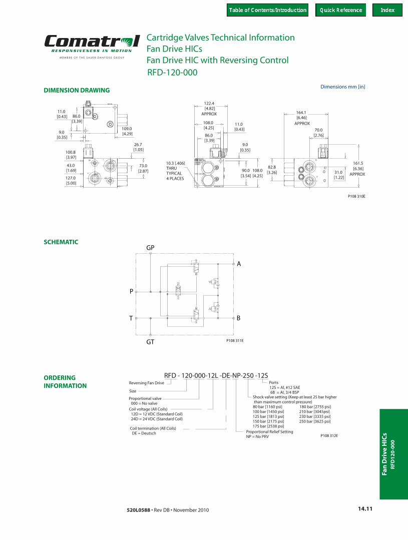
Cartridge Valves Technical InformationFan Drive HICs
SCHEMATIC
DIMENSION DRAWING
ORDERING INFORMATION
RFD-120-000Fan Drive HIC with Reversing Control
161.5[6.36]
31.0 [1.22]
70.0[2.76]
164.1 [6.46]
82.8[3.26]108.0
[4.25]90.0
[3.54]
9.0[0.35]
122.4 [4.82]
108.0 [4.25]
86.0 [3.39]
11.0 [0.43]
10.3 [.406] THRUTYPICAL 4 PLACES
11.0 [0.43]
9.0 [0.35]
86.0 [3.39]
109.0 [4.29]
26.7 [1.05]
73.0[2.87]
127.0 [5.00]
43.0 [1.69]
100.8 [3.97]
APPROX
APPROX
APPROX
P108 310E
Dimensions mm [in]
P108 311E
A
B
GT
GP
P
T
Proportional valve 000 = No valve
Size
Reversing Fan Drive
Coil termination (All Coils) DE = Deutsch
RFD - 120-000-12L -DE-NP-250 -12S
Proportional Relief SettingNP = No PRV
Ports 12S = Al, #12 SAE 6B = Al, 3/4 BSP
Coil voltage (All Coils) 12D = 12 VDC (Standard Coil) 24D = 24 VDC (Standard Coil)
Shock valve setting (Keep at least 25 bar higher than maximum control pressure)80 bar [1160 psi] 180 bar [2755 psi]100 bar [1450 psi] 210 bar [3045psi]125 bar [1813 psi] 230 bar [3335 psi]150 bar [2175 psi] 250 bar [3625 psi] 175 bar [2538 psi]
P108 312E
RFD
12
0-0
00

Fan D
rive HIC
s
14.12 520L0588 • Rev DB • November 2010
Cartridge Valves Technical InformationFan Drive HICs
SPECIFICATIONS
OPERATION
THEORETICAL PERFORMANCE
0
5
10
15
20
25
30
35
40
0 5 10 15 20 25 30 35 40 45 50
bar
l/min
Pressure drop33 cSt[154 SUS] hyd.oil@38° C[100° F]
0
72
145
218
290
363
435
508
580psi
0 1.3 2.6 4.0 5.3 6.6 7.9 9.2 10.6 11.9 13.2gal/min
P A B T
P-B-A
- - -
-T
∆Pr
essu
re
I
WUS
Y
Q
OM
bar
F
Current
25 0
00 0.4 0.8(12 V)
(24 V)1.1
20 0
150
100
50
0
1000
2000
3000
psi
A0
0.2 0.4 0.55
Pressure vs Current33 cSt[154 SUS] hyd.oil@38°
30 0
20 0
150
25 0
100
50
Pres
sure
I
YWUSQOM
0l/mi n80604020
00
208 16124 gal/min
1000
2000
3000
barpsi
4000
F
Bypass �ow0
∆
Pressure drop33 cSt[154 SUS] hyd.oil@38°
P108 303E
C[100° F]
C[100° F]
RFD-40-PRVFan Drive HIC with Proportional and Reversing Control
Rated pressure 210 bar [3000 psi]
Flow Up to 40 l/min [10.5 US gal/min]
See performance chart
Weight 4.52 kg [9.96 lb]
Valves DCV03, PRV10-IS2, PVLP
Gauge Port Size #4 SAE [1/4 BSP]
This valve regulates fan speed by controlling pressure drop across the fan motor. It operates in a normally closed configuration in the absence of an electrrical signal.
The valve reverses flow to the fan motor to reverse fan direction. It includes an open transition spool to reduce pressure spikes during reversals.
It trims the maximum motor torque by absorbing pressure spikes at the work ports. An anti-cavitation feature allows additional flow to the motor when the motor over-runs the pump.
RFD
40
-PR
V

Fan
Dri
ve H
ICs
14.13520L0588 • Rev DB • November 2010
Cartridge Valves Technical InformationFan Drive HICs
SCHEMATIC
DIMENSION DRAWING
ORDERING INFORMATION
P108 301E
A
B
TG
PG
P
T
157.4[6.20]
27.6[1.09]
29.8 [1.17]
44.8 [1.76]
197.9 [7.79]
86.4[3.40]
68.4[2.69]
9.0 [0.35]
9.0 [0.35]
106.1 [4.18]
81.1 [3.19]
18.0 [0.71]
58.0 [2.28]
43.4 [1.71]
38.8 [1.53]
79.8 [3.14]
81.1 [3.19]
9.0 [0.35]
9.0 [0.35]
8.5 [.335] THRUTYPICAL 4 PLACES
99.1 [3.90] APPROX
APPROX68.2
[2.69]97.8
[3.85]
APPROX
P108 304E
Proportional valvePRV=Proportional Relief Valve000 = No valve
Size
Reversing Fan Drive
Coil termination (All Coils) DE = Deutsch
RFD- 40 -PRV -12L -DE-Y -250 -8S
Proportional Relief SettingF=45 bar[653 psi] O=120 bar[1740 psi] U=185 bar[2683 psi]I=75 bar[1088 psi] Q=140 bar[2030 psi] W=205 bar[2973 psi]M=100 bar[1450 psi] S=160 bar[2320 psi] Y=225 bar[3263 psi]
Ports 8S = Al, #8 SAE
4B = Al, 1/2 BSP
Coil voltage (All Coils) 12L = 12 VDC (Standard Coil) 24L = 24 VDC (Standard Coil)
Shock valve setting (Keep at least 25 bar higher than maximum control pressure)80 bar [1160 psi] 180 bar [2755 psi]100 bar [1450 psi] 210 bar [3045psi]125 bar [1813 psi] 230 bar [3335 psi]150 bar [2175 psi] 250 bar [3625 psi] 175 bar [2538 psi]
P108 303E
Dimensions mm [in]
RFD-40-PRVFan Drive HIC with Proportional and Reversing Control
RFD
40
-PR
V

Fan D
rive HIC
s
14.14 520L0588 • Rev DB • November 2010
Cartridge Valves Technical InformationFan Drive HICs
SPECIFICATIONS
OPERATION
THEORETICAL PERFORMANCE
RFD-80-PRVFan Drive HIC with Proportional and Reversing Control
0
5
10
15
20
25
30
0 10 20 30 40 50 60 70 80 90 1000
73
145
218
290
363
435
0 2.6 5.3 7.9 10.6 13.2 15.8 18.5 21.1 23.7 26.4
Pressure drop33 cSt[154 SUS] hyd.oil@38° C[100° F]
barpsi
l/min
gal/min
P A B T- - -
P-B-A-T
psi
0.550.40.20
(A)
3000
2000
1000
0
50
100
150
20 0
1.1(24 V)(12 V) 0.80.40
0
25 0
∆Pr
essu
re
WU
SQ O
M
bar
F
Curren t
R
Pressure vs Current33 cSt[154 SUS] hyd.oil@38°
30 0
20 0
150
25 0
100
50
Pres
sure
I
WU
S R
Q OM
0l/mi n
0
gal/min
1000
2000
3000
barpsi
4000
F
Bypass �ow4 12 168 20 0
04 08 01 20 160
∆
Pressure drop33 cSt[154 SUS] hyd.oil@38°
P108 313E
C[100° F]
C[100° F]
Rated pressure 210 bar [3000 psi]
Flow Up to 80 l/min [21.7 US gal/min]
See performance chart
Weight 8.35 kg [18.40 lb]
Valves DCV05, PRV12-IS2, PVLP
Gauge Port Size #4 SAE [1/4 BSP]
This valve regulates fan speed by controlling pressure drop across the fan motor. It operates in a normally closed configuration in the absence of an electrrical signal.
The valve reverses flow to the fan motor to reverse fan direction. It includes an open transition spool to reduce pressure spikes during reversals.
It trims the maximum motor torque by absorbing pressure spikes at the work ports. An anti-cavitation feature allows additional flow to the motor when the motor over-runs the pump.
RFD
80
-PR
V

Fan
Dri
ve H
ICs
14.15520L0588 • Rev DB • November 2010
Cartridge Valves Technical InformationFan Drive HICs
SCHEMATIC
DIMENSION DRAWING
ORDERING INFORMATION
RFD-80-PRVFan Drive HIC with Proportional and Reversing Control
P108 315E
A
B
TG
PG
P
T
188.2[7.41]
40.5[1.59]
82.9[3.26]
231.9 [9.13]
43.4 [1.71]
71.9 [2.83]200
[7.9]
115.0 [4.53]
108.0 [4.25]
90.0 [3.54]
9.0[0.35]
9.0[0.35]
90.0[3.54]
108.0[4.25]
8.5 [.335] THRUTYPICAL 4 PLACES
9.0 [0.35]
9.0 [0.35] 90.0
[3.54]115.4 [4.54]
31.0[1.22]73.4
[2.89]
133.4 [5.25]
42.4 [1.67]
77.5[3.05]
APPROX
APPROX
APPROX
P108 314E
Proportional valvePRV=Proportional Relief Valve000 = No valve
Size
Reversing Fan Drive
Coil termination (All Coils) DE = Deutsch
RFD -80- PRV- 12L -DE-W-250-10S
Proportional Relief SettingF=55 bar[798 psi] O=125 bar[1813 psi] U=185 bar[2683 psi]I=85 bar[1233 psi] Q=135 bar[1958 psi] W=205 bar[2973 psi]M=105 bar[1523 psi] S=155 bar[2248 psi]
Ports 10S = Al, #10 SAE 6B = Al, 3/4 BSP
Coil voltage (All Coils) 12D = 12 VDC (Standard Coil) 24D = 24 VDC (Standard Coil)
Shock valve setting (Keep at least 25 bar higher than maximum control pressure)80 bar [1160 psi] 180 bar [2755 psi]100 bar [1450 psi] 210 bar [3045psi]125 bar [1813 psi] 230 bar [3335 psi]150 bar [2175 psi] 250 bar [3625 psi] 175 bar [2538 psi]
P108 116E
Dimensions mm [in]
RFD
80
-PR
V

Fan D
rive HIC
s
14.16 520L0588 • Rev DB • November 2010
Cartridge Valves Technical InformationFan Drive HICs
SPECIFICATIONS
OPERATION
THEORETICAL PERFORMANCE
RFD-120-PRVFan Drive HIC with Proportional and Reversing Control
0
2
4
6
8
10
12
14
0 10 20 30 40 50 60 70 80 90 100 110 120
P-A-B-T, P -B-A-T
Pressure drop33 cSt[154 SUS] hyd.oil@38° C[100° F]
0 2.6 5.3 7.9 10.6 13.2 15.9 18.4 21.1 23.7 26.4 29.1 31.7
0
29
58
87
116
145
174
203
l/min
gal/min
barpsi
psi
0.550.40.20
(A)
3000
2000
1000
0
50
100
150
20 0
1.1(24 V)(12 V) 0.80.40
0
25 0
∆Pr
essu
re
WU
SQ O
M
bar
F
Current
R
Pressure vs Current33 cSt[154 SUS] hyd.oil@38°
30 0
20 0
150
25 0
100
50
Pres
sure
I
WU
S R
Q OM
0l/mi n
0
gal/min
1000
2000
3000
barpsi
4000
F
Bypass �ow4 12 168 20 0
04 08 01 20 160
∆
Pressure drop33 cSt[154 SUS] hyd.oil@38°
P108 317E
C[100° F]
C[100° F]
Rated pressure 210 bar [3000 psi]
Flow Up to 120 l/min [31.7 US gal/
min]
See performance chart
Weight 15.7 kg [6.93 lb]
Valves CP722-5, SV08-24-01, PRV12-IS2,
PVLP
Gauge Port Size #4 SAE [1/4 BSP]
This valve regulates fan speed by controlling pressure drop across the fan motor. It operates in a normally closed configuration in the absence of an electrrical signal.
The valve reverses flow to the fan motor to reverse fan direction. It includes an open transition spool to reduce pressure spikes during reversals.
It trims the maximum motor torque by absorbing pressure spikes at the work ports. An anti-cavitation feature allows additional flow to the motor when the motor over-runs the pump.
RFD
12
0-P
RV

Fan
Dri
ve H
ICs
14.17520L0588 • Rev DB • November 2010
Cartridge Valves Technical InformationFan Drive HICs
SCHEMATIC
DIMENSION DRAWING
ORDERING INFORMATION
RFD-120-PRVFan Drive HIC with Proportional and Reversing Control
P108 319E
A
B
GT
GP
P
T
223.6 [8.80]
31.0[1.22]
176.8 [6.96]
82.7[3.26]
100.0[3.94]125.0
[4.92]107.0[4.21]
9.0[0.35]
129.4 [5.09]
103.0 [4.06]
125.0 [4.92]
10.3 [.406] THRUTYPICAL 4 PLACES
11.0 [0.43]
90.0[3.54]
26.8 [1.05]
55.7 [2.19]
139.7 [5.50]
113.6 [4.47]
121.7 [4.79]
103.0[4.06]
11.0 [0.43]
9.0 [0.35]
APPROX
APPROX
APPROX
P108 318E
Proportional valvePRV=Proportional Relief Valve000 = No valve
Size
Reversing Fan Drive
Coil termination (All Coils) DE = Deutsch
RFD -120 -PRV -12L -DE-W-250-12SPorts 12S = Al, #12 SAE 6B = Al, 3/4 BSP
Coil voltage (All Coils) 12D = 12 VDC (Standard Coil) 24D = 24 VDC (Standard Coil)
Shock valve setting (Keep at least 25 bar higher than maximum control pressure)80 bar [1160 psi] 180 bar [2755 psi]100 bar [1450 psi] 210 bar [3045psi]125 bar [1813 psi] 230 bar [3335 psi]150 bar [2175 psi] 250 bar [3625 psi] 175 bar [2538 psi] Proportional Relief Setting
F=55 bar[798 psi] O=125 bar[1813 psi] U=185 bar[2683 psi]I=85 bar[1233 psi] Q=135 bar[1958 psi] W=205 bar[2973 psi]M=105 bar[1523 psi] S=155 bar[2248 psi]
P108 120E
Dimensions mm [in]
RFD
12
0-P
RV

Fan D
rive HIC
s
14.18 520L0588 • Rev DB • November 2010
Cartridge Valves Technical InformationFan Drive HICsNotes