carbon fiber reinforced glass matrix composites …pitch fiber reinforced glass matrix composites...
TRANSCRIPT
R89-917704-1
CARBON FIBER REINFORCEDGLASS MATRIX COMPOSITES FOR
STRUCTURAL SPACE BASEDo APPLICATIONSto
(Prepared byI
W. K. TredwayK. M. Prewo
FINAL REPORT
Contract N0001 4-85-C-0332
for
Department of the NavyOffice of Naval Research
Arlington, VA 22217
July 31, 1989 DTIC[.1: U3 2,11339
SUNITEDTECHNOLOGIES,RESEARCH
CENTERUt Herford, Co,"chmut 06106
J D'.+,.: ,-': i.! m + ,
UNCL ASSIFIEDSECURITY CLASSIFICATION OF THIS PAGE
Form ApprovedREPORT DOCUMENTATION PAGE OMB No. 0704-0188
Ia. REPORT SECURITY CLASSIFICATION lb. RESTRICTIVE MARKINGS
Unclassified None
2a. SECURITY CLASSIFICATION AUTHORITY 3. DISTRIBUTION/AVAILABILITY OF REPORT
2b. DECLASSIFICATION / DOWNGRADING SCHEDULE Unlimited
4. PERFORMING ORGANIZATION REPORT NUMBER(S) S. MONITORING ORGANIZATION REPORT NUMBER(S)
R89-917704-1
6a. NAME OF PERFORMING ORGANIZATION 6b. OFFICE SYMBOL 7a. NAME OF MONITORING ORGANIZATIONUnited Technologies (If applicable)
Research Center Office of Naval Research
6c. ADDRESS (City, State, and ZIP Code) 7b. ADDRESS (City, State, and ZIP Code)
East Hartford, CT 06108 Arlington, VA 22217
8a. NAME OF FUNDING /SPONSORING 8b. OFFICE SYMBOL 9 PROCUREMENT INSTRUMENT IDENTIFICATION NUMBERORGANIZATION (If applicable)
Office of Naval Research N00014-85-C-0332
Bc. ADDRESS (City, State, and ZIP Code) 10. SOURCE OF FUNDING NUMBERSPROGRAM PROJECT TASK WORK UNIT
Arlington, VA 22217 ELEMENT NO. NO. NO ACCESSION NO.
11. TITLE (Include Security Classification)
CARBON FIBER REINFORCED GLASS MATRIX COMPOSITES FOR STRUCTURAL SPACEBASED APPLICATIONS
12. PERSONAL AUTHOR(S)
W. K. Tredway and K. M. Prewo13a. TYPE OF REPORT |13b. TIME COVERED 114. DATE OF REPORT (Year, Month, Day) 15. PAGE COUNT
FinalI FROM2/1/87 TO5/31.LB 1989 July 31 10416. SUPPLEMENTARY NOTATION
17. COSATI CODES 18. SUBJECT TERMS (Continue on reverse if necessary and identify by block number)
FIELD GROUP SUB-GROUP ,,Glass Matrix Composites.Carbon Fiber Reinforced CompositesGlass-Ceramic Matrix Composites ,
19. ABSTRACT (Continue on reverse if necessary and identify by block number)
A variety of ultra-high elastic modulus pitch-based carbon fibers were combined with several different glass and glass-ceramic matrix compositions to produce unidirectionally reinforced composites. Composite performance was evaluated inseveral different areas, including tensile stress-strain behavior, flexural properties at both room and elevated temperature,thermal expansion, and fracture behavior. Pitch fiber reinforced glass matrix composites demonstrated high tensile strength
(540-790 MPa), high elastic modulus (300-350 GPa), and high specific stiffness (135-165 x 107 cm). Residual matrix tensile
stress resulting from differential thermal contraction between fiber and matrix was shown to have a strong influence oncomposite behavior. Ptch/Glass composites were found to exhibit fairly linear coefficient of thermal expansion behavior inthe longitudinal direction over the temperature range of -1506C to +1000C. High temperature matrix compositions weredeveloped which maintained the excellent tensile properties of pitch fiber reinforced composites while giving them thecapability to preserve structural integrity up to temperatures of at least 800t. --Composition was found to have a stronginfluence on the wetting behavior of glasses on carbon fibers. Oxycarbide glasses demonstrated enhanced wettingbehavior on carbon fibers as well as resisting devitrification at temperatures as high as 11 000C.
20. DISTRIBUTION/ AVAILABILITY OF ABSTRACT 21. ABSTRACT SECURITY CLASSIFICATIONMUNCLASSIFIED/UNLIMITED 0 SAME AS RPT. C DTIC USERS None
22a. NAME OF RESPONSIBLE INDIVIDUAL 22b. TELEPHONE (Include Area Code) 22c. OFFICE SYMBOLDr. S. Fishman,ONR (202) 696-4401 ONR/1131
DD Form 1473, JUN 86 Previous editions are obsolete. SECURITY CLASSIFICATION OF THIS PAGE
UNCLASSIFIED
R89-917704-1
Carbon Fiber Reinforced Glass Matrix Composites forStructural Space Based Applications
FINAL REPORT
Contract N00014-85-C-0332
William K. Tredway
'Karl M. Prewo
APPROVED BYEarl R. Thompson
DATE July 31. 1989
R89-917704-1
TABLE OF CONTENTS
I. INTRODUCTION...........................................1
II. EXPERIMENTAL PROCEDURE .................................................... 4
III. MECHANICAL PROPERTIES OF PITCH FIBER REINFORCEDGLASS MATRIX COMPOSITES .................................................... 9
IV. IMPROVED MECHANICAL BEHAVIOR IN PITCH FIBER REINFORCEDGLASS MATRIX COMPOSITES THROUGH MATRIX MODIFICATION ..... 36
V. THERMAL EXPANSION BEHAVIOR OF PITCH FIBER REINFORCEDGLASS MATRIX COMPOSITES .................................................... 47
VI. DEVELOPMENT OF HIGH TEMPERATURE MATRICES FOR
CARBON FIBER REINFORCED GLASSES ....................................... 51
VII. INTERFACE REACTIONS AND WETTING IN CARBON FIBERREINFORCED GLASS MATRIX COMPOSITES .................................. 63
VIII. SOL/GEL PROCESSING OF OXYCARBIDE GLASSESAND GLASS MATRIX COMPOSITES ............................................. 88
IX . D ELIV ERA BLES ......................................................................... 101
X . SU M M A R Y .............................................................................. 102
Accession For
NTIS GRA&I
DTIG TAB ElUnanncunced 0lJust if bat ton
By
Dtstribution/
Avnilability Codes
D Avail and/or
Dist Special
R89-917704-1
I. INTRODUCTION
The carbon fiber reinforced glass matrix composite system provides a unique opportunityfor the basic investigation of mechanisms controlling ceramic matrix composites behavior and atthe same time develop a material eminently suited to structural space based applications. TheUnited Technologies Research Center and Pennsylvania State University have joined in theherein reported activity to characterize, understand, and improve the performance of carbon fiberreinforced glass. Carbon fiber reinforced glass composites have been fabricated and studied byseveral investigators over the past years in an attempt to develop a composite having performancesuperior to that of carbon reinforced resins and metals [1-10]. This investigation, which wasbegun in mid-1985, focused during the first two years on understanding the behavior in glassmatrix composites reinforced with Hercules HMU carbon fiber [11, 12]. Use of this fiberallowed for reliable interpretation of the mechanisms controlling the tensile stress-strain behaviorand resulted in unidirectionally reinforced composites possessing excellent tensile strength andstiffnesses in the range of 160-180 GPa [10, 11]. Currently, the focus of the investigation hasshifted to composites exhibiting higher moduli as a result of SDI requirements for increasedspecific stiffness in space structures. To this end, ultra-high modulus pitch-based carbon fiberspossessing stiffnesses greater than 690 GPa have been incorporated as the reinforcement forglass and glass-ceramic matrix composites with considerable success.
In the herein described investigation, the performance of glass and glass-ceramic matrixcomposites containing ultra-high modulus pitch-based carbon fibers is discussed. The nature ofthe fiber-matrix interface and the effect of fiber-matrix adhesion on composite properties isemphasized throughout the investigation. The tensile stress-strain behavior of these highmodulus composite systems is described and related to that of HMU reinforced glass matrixcomposites. Flexural behavior, thermal expansion, and fracture behavior are also discussed.The development of high temperature matrices for these high modulus composite systems and theresulting mechanical behavior of these composites is also included. In addition, studiesconducted at Penn State University concerning fiber-matrix interfacial wetting and thedevelopment of oxycarbide glass matrices and carbon fiber reinforced composites containingthese matrices are described.
This program supported by the Strategic Defense Initiative Office/Innovative Science andTechnology under ONR contract N00014-85-C-0332.
1
R89-917704-1
The program participants are:
William K Tredway UTRCKarl M. Prewo UTRC
Carlo G. Pantano Penn State UniversityDongxin Qi Penn State UniversityG. Chen Penn State UniversityHanxi Zhang Penn State University
REFERENCES
1. I. Crivelli-Visconti and G. A. Cooper, "Mechanical Properties of a New Carbon ioerMaterial," Nature, 221 (1969) 754-755.
2. R. A. j. Sambell, et al., "Carbon Fibre Composites With Ceramic and Glass Matrices - Part2. Continuous Fibres," J Mater. Sci., 7 (1972) 676-681.
3. R. A. J. Sambell, D. H. Bowen and D. C. Phillips, "Carbon Fibre Composites WithCeramic and Glass Matrices - Part 1. Discontinuous Fibres," J. Mater. Sci., 7 (1972) 663-675.
4. D. C. Phillips, R. A. J. SambeU and D. H. Bowen, "The Mechanical Properties of CarbonFibre Reinforced Pyrex Glass," J. Mater. Sci., 7 (1972) 1454-1464.
5. D. C. Phillips, "Interfacial Bonding and the Toughness of Carbon Fibre Reinforced Glassand Glass-Ceramics," J. Mater. Sci., 9 (1974) 1847-1854.
6. K. M. Prewo and J. F. Bacon, "Glass Matrix Composites - I - Graphite Fiber ReinforcedGlass," Proceedings of ICCM/2 - The 1978 International Conference on Composite Materials,Toronto, Canada, 1978, pp. 64-74.
7. K. M. Prewo, J. F. Bacon and D. L. Dicus, "Graphite Fiber Reinforced Glass MatrixComposites," SAMPE Quart., 10 (1979).
8. K. M. Prewo, "A Compliant, High Failure Strain, Fibre-Reinforced Glass-MatrixComposite," J. Mater. Sci., 17 (1982) 3549-3563.
9. K. M. Prewo, "Carbon Fibre Reinforced Glass Matrix Composite Tension and FlexureProperties," J. Mater. Sci., 23 (1988) 2745-2752.
2
R89-917704-1
10. V. C. Nardone and K. M. Prewo, "Tensile Performance of Carbon-Fibre-ReinforcedGlass," J. Mater. Sci., 23 (1988) 168-180.
11. K. M. Prewo and V. C. Nardone, "Carbon Fiber Reinforced Glass Matrix Composites forSpace Based Applications," UTRC Report R86-917161-1, ONR Annual Report, September 15,1986.
12. W. K. Tredway and K. M. Prewo, "Carbon Fiber Reinforced Glass Matrix Composites forSpace Based Applications," UTRC Report R87-917470-1, ONR Annual Report, August 30,1987.
3
R89-917704-1
II. EXPERIMENTAL PROCEDURE
A. Composite Fabrication
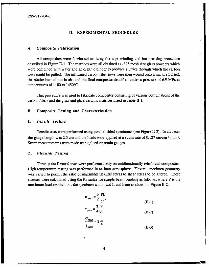
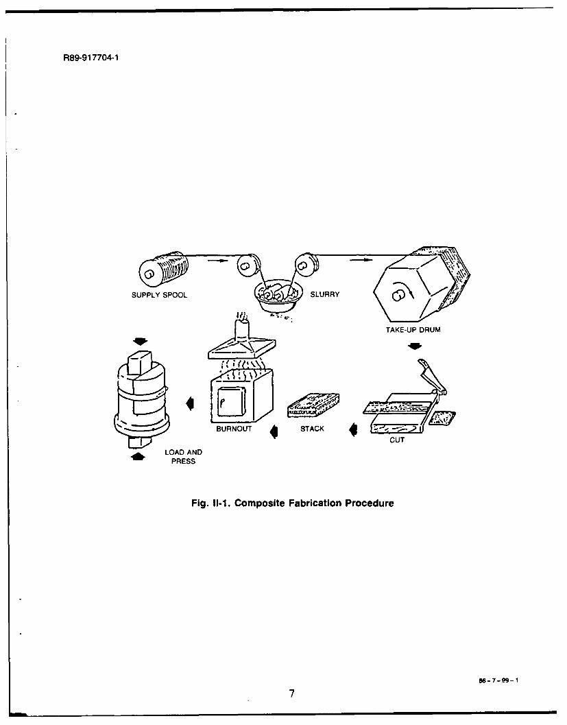
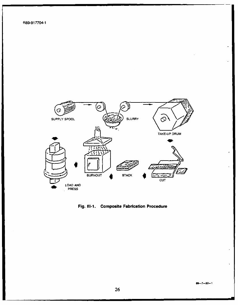
All composites were fabricated utilizing the tape winding and hot pressing proceduredescribed in Figure 11-1. The matrices were all obtained as -325 mesh size glass powders whichwere combined with water and an organic binder to produce slurries through which the carbontows could be pulled. The infiltrated carbon fiber tows were then wound onto a mandrel, dried,the binder burned out in air, and the final composite densified under a pressure of 6.9 MPa attemperatures of 1100 to 1450'C.
This procedure was used to fabricate composites consisting of various combinations of thecarbon fibers and the glass and glass-ceramic matrices listed in Table 11-1.
B. Composite Testing and Characterization
1. Tensile Testing
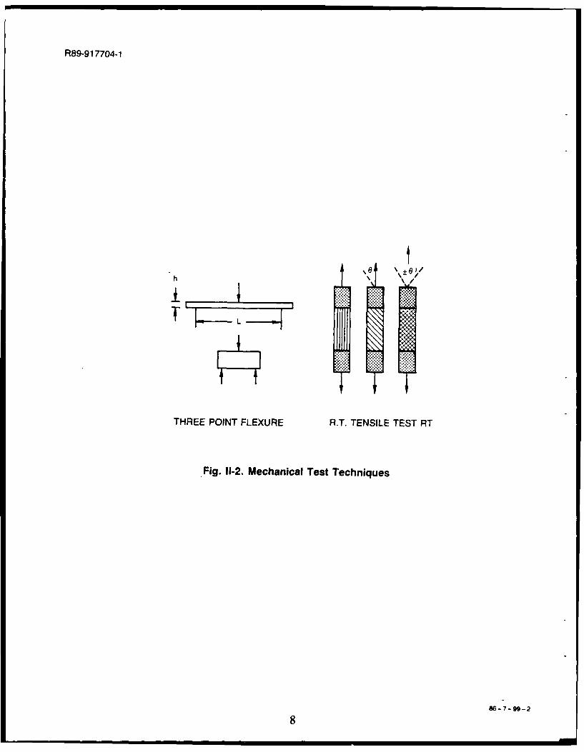
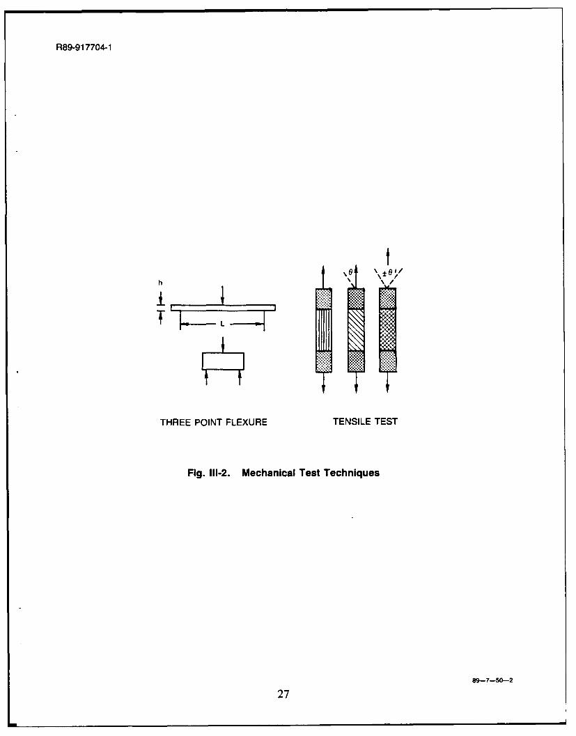
Tensile tests were performed using parallel sided specimens (see Figure 1-2). In all cases
the gauge length was 2.5 cm and the loads were applied at a strain rate of 0.127 cm-cm-1 -min-1.Strain measurements were made using glued-on strain gauges.
2. Flexural Testing
Three-point flexural tests were performed only on unidirectionally reinforced composites.High temperature testing was performed in an inert atmosphere. Flexural specimen geometrywas varied to permit the ratio of maximum flexural stress to shear stress to be altered. Thesestresses were calculated using the formulae for simple beam bending as follows, where P is themaximum load applied, b is the specimen width, and L and h are as shown in Figure 11-2.
3 PLOmax 2 bh2 (I-1)
3P'tmax 4 bh (11-2)
-ma = 2 L0Emax h
maax L4(1-3)
4
R89-917704-1
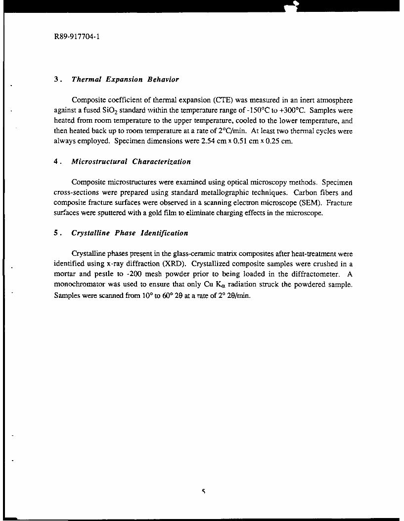
3. Thermal Expansion Behavior
Composite coefficient of thermal expansion (CTE) was measured in an inert atmosphereagainst a fused SiO 2 standard within the temperature range of -150'C to +300'C. Samples wereheated from room temperature to the upper temperature, cooled to the lower temperature, andthen heated back up to room temperature at a rate of 2°C/min. At least two thermal cycles werealways employed. Specimen dimensions were 2.54 cm x 0.51 cm x 0.25 cm.
4. Microstructural Characterization
Composite microstructures were examined using optical microscopy methods. Specimencross-sections were prepared using standard metallographic techniques. Carbon fibers andcomposite fracture surfaces were observed in a scanning electron microscope (SEM). Fracturesurfaces were sputtered with a gold film to eliminate charging effects in the microscope.
5. Crystalline Phase Identification
Crystalline phases present in the glass-ceramic matrix composites after heat-treatment wereidentified using x-ray diffraction (XRD). Crystallized composite samples were crushed in amortar and pestle to -200 mesh powder prior to being loaded in the diffractometer. Amonochromator was used to ensure that only Cu Ka radiation struck the powdered sample.
Samples were scanned from 100 to 600 20 at a rate of 20 20/min.
R89-917704-1
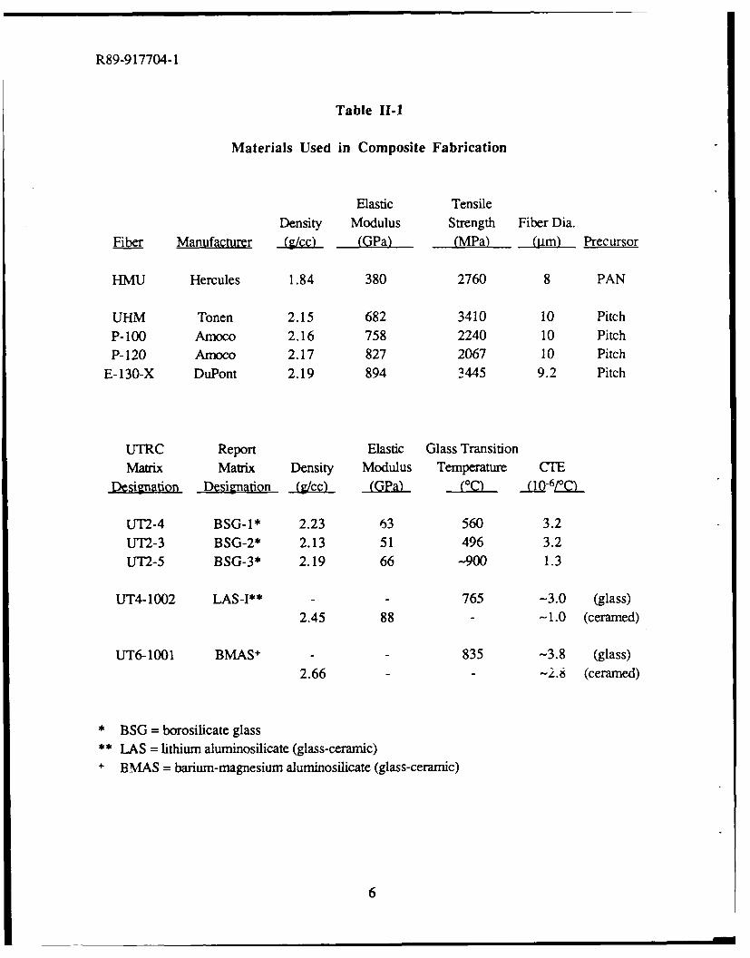
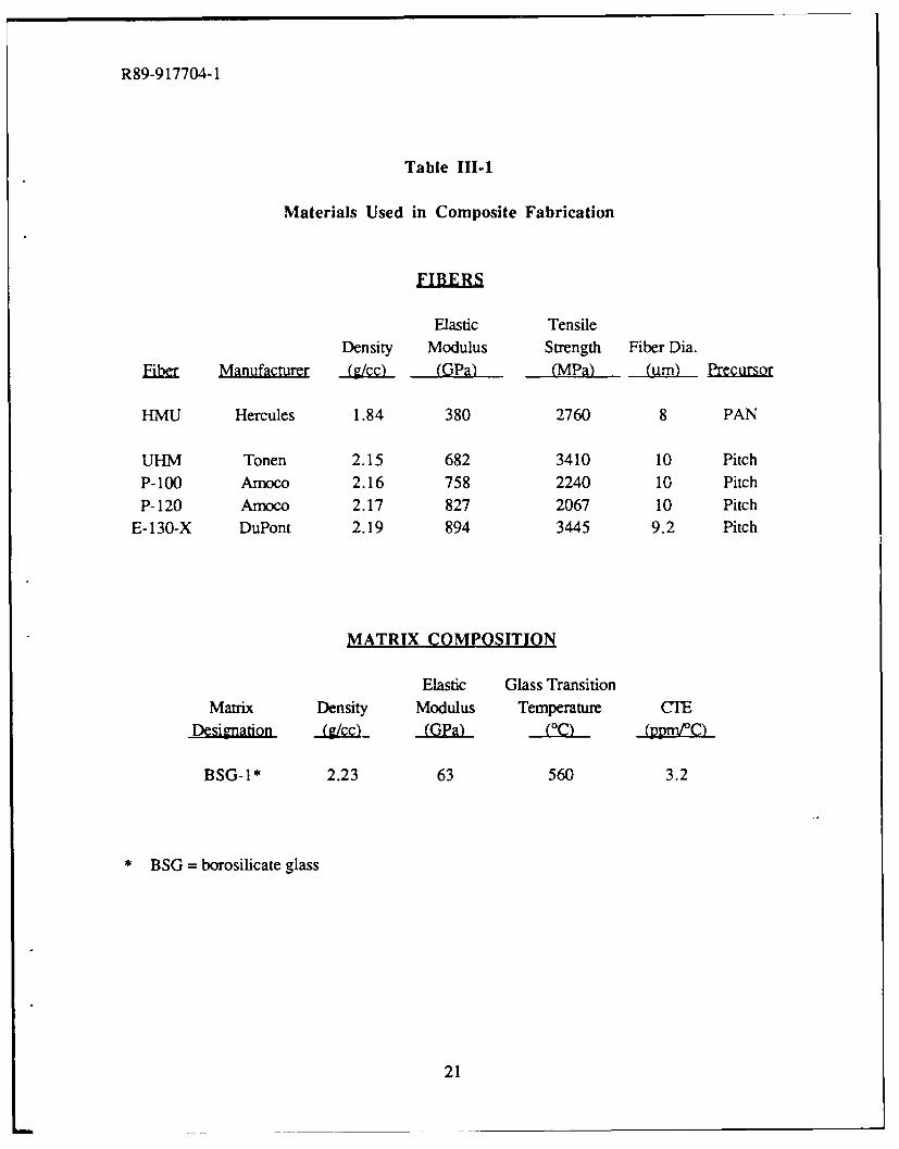
Table Il-
Materials Used in Composite Fabrication
Elastic TensileDensity Modulus Strength Fiber Dia.
Fiber Manufacturer (.cc) (GPa) (MPa) (iLm) Precursor
HMU Hercules 1.84 380 2760 8 PAN
UHM Tonen 2.15 682 3410 10 PitchP-100 Amoco 2.16 758 2240 10 PitchP- 120 Amoco 2.17 827 2067 10 Pitch
E-130-X DuPont 2.19 894 3445 9.2 Pitch
UTRC Report Elastic Glass TransitionMatrix Matrix Density Modulus Temperature CTE
Designation Designation (iLYcc) (GPa) ,(0 (10-6C
UT'2-4 BSG-I* 2.23 63 560 3.2UT2-3 BSG-2* 2.13 51 496 3.2UT2-5 BSG-3* 2.19 66 -900 1.3
UT4-1002 LAS-I** - - 765 -3.0 (glass)
2.45 88 - -1.0 (ceramed)
UT6-1001 BMAS + - - 835 -3.8 (glass)
2.66 - -2.8 (ceramed)
* BSG = borosilicate glass
* LAS = lithium aluminosilicate (glass-ceramic)+ BMAS = barium-magnesium aluminosilicate (glass-ceramic)
6
R89-917704-1
SUPPLY SPOOL
TAKE-UP DRUM
BURNOUT STACK CUT
LOAD ANDPRESS
Fig. I1-1. Composite Fabrication Procedure
86-7-99-1
7
R89-9 17704-1
THREE POINT FLEXURE R.T. TENSILE TEST RT
' Fig. 11-2. Mechanical Test Techniques
86-7-99-2
R89-917704-1 (This chapter to be submitted for publication)
lIl. MECHANICAL PROPERTIES OF PITCH FIBER REINFORCEDGLASS MATRIX COMPOSITES
A. Introduction
The reinforcement of ceramics with fibers has proven to be a successful means ofimproving the toughness of these inherently brittle materials. The incorporation of carbon fibersinto glasses to produce high strength, tough composite materials was demonstrated more than adecade ago by researchers in the U. K. [1-4]. Development of the carbon fiber reinforced glass(C/Glass) composite system was then continued in the U. S. [5-8], with the most recent studiesfocusing on the use of Hercules HMU carbon fiber in borosilicate glass matrices [9-11]. Theunique combination of properties demonstrated by C/Glass composites (high strength andstiffness, excellent toughness, low density, dimensional staoility, excellent tribologicalcharacteristics, high impact resistance, environmental stability) makes them likely candidates forstructural applications previously reserved for polymer and metal matrix composites, such as gasturbine engine components and structural members in space-based applications. Perhaps themore exotic of these applications is as structural components in satellites and other space-orientedsystems. Materials suited for these roles must be structurally sound, lightweight, and able towithstand the severe conditions imposed by the space environment.
One of the critical requirements of materials for space structures is that they demonstratehigh specific stiffness (stiffness divided by density). In order to meet this demand, researchers
have had to utilize ultra-high modulus carbon fibers made from mesophase pitch precursors [12].These fibers, which exhibit a high degree of graphitization in their internal structure, typicallypossess tensile elastic moduli in the range of 690-900 GPa. Implementation of these ultra-highmodulus fibers in C/Glass composites, which is the subject of this study, has met with reason-ably good success; however, the nature of the tensile stress-strain behavior and the fracturebehavior have been found to differ significantly from that of C/Glass composites reinforced withHMU carbon fiber [11]. The cause of these variations is thought to be related to differences inthe nature of the fiber-matrix interface, primarily in the degree of fiber-matrix adhesion displayedin the two composite systems [ 13]. Matrix microcracking strain, fiber pullout length, and workof fracture are all kmown to be strong functions of fiber-matrix interfacial strength.
This .- describes the results of an effort to investigate the mechanical performance andfracture bt /.or of glass matrix composites reinforced with ultra-high modulus pitch-basedcarbon fiber. 7 ''-r nsile stress-strain characteristics, flexural behavior, and fracture morphologyof C/Glt, s r;cr.posites reinforced with several types of pitch-based carbon fiber will bediscussed and compared to those characteristics of HMU reinforced C/Glass composites. Theinfluence of fiber-matrix interfacial adhesion on these properties will be emphasized.
9
R89-917704-1
B. Experimental Procedure
All composites were fabricated utilizing the tape winding and hot pressing proceduredescribed in Figure HI-1. The matrix was obtained as -325 mesh size glass powder which wascombined with water and an organic binder to produce a slurry through which the carbon towscould be pulled. The infiltrated carbon fiber tows were then wound onto a mandrel, dried, thebinder burned out in air, and the final composite densified under a pressure of 6.9 MPa at atemperature of -1250'C. This procedure was used to fabricate composites consisting of thecarbon fibers and the glass matrix composition listed in Table n1-1. All the composites in thisstudy were unidirectional in fiber orientation.
Tensile tests were performed using parallel sided specimens (see Figure III-2). In all cases
the gauge length was 2.5 cm and the loads were applied at a strain rate of 0.127 cm-cm-1 min-1.Strain measurements were made using glued-on strain gauges.
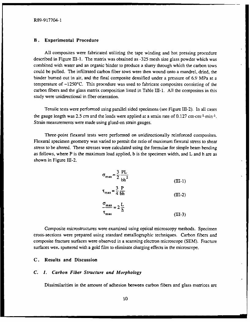
Three-point flexural tests were performed on unidirectionally reinforced composites.Flexural specimen geometry was varied to permit the ratio of maximum flexural stress to shearstress to be altered. These stresses were calculated using the formulae for simple beam bendingas follows, where P is the maximum load applied, b is the specimen width, and L and h are asshown in Figure 111-2.
3 PLGmax 2 bh2 (n-1)
3PTmax = 4 bh (HII-2)
0Ymax L-=2-'Tmax h (111-3)
Composite microstructures were examined using optical microscopy methods. Specimencross-sections were prepared using standard metallographic techniques. Carbon fibers andcomposite fracture surfaces were observed in a scanning electron microscope (SEM). Fracturesurfaces wert. sputtered with a gold film to eliminate charging effects in the microscope.
C. Results and Discussion
C. 1. Carbon Fiber Structure and Morphology
Dissimilarities in the amount of adhesion between carbon fibers and glass matrices are
10
R89-917704-1
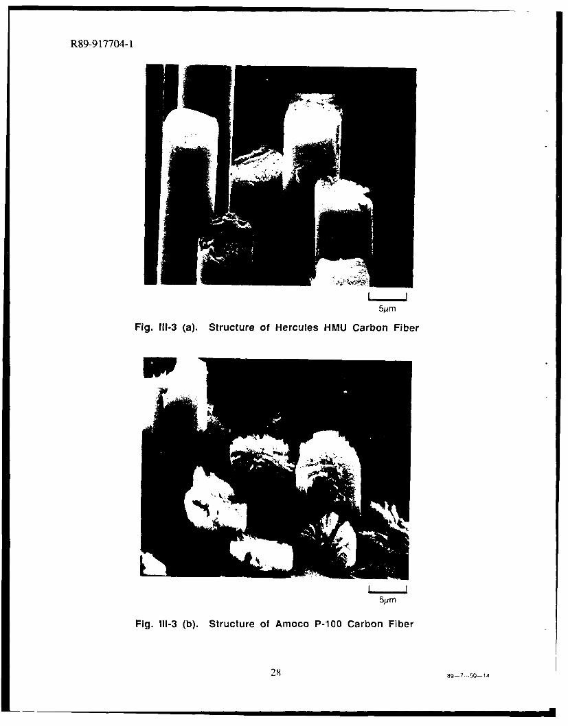
related to a number of factors, including internal fiber structure, surface structure, and surfacechemistry. Carbon fibers derived from polyacrylonitrile (PAN) and mesophase pitch precursorsare typically characterized by differences in all three of these characteristics [14, 15]. HerculesHMU fiber, which is an intermediate modulus PAN-derived carbon fiber, is typified by aninternal fiber structure which resembles a 'rolled-up newspaper' in appearance (Figure III-3(a)).The graphite planes are aligned parallel to the fiber axis, but the degree of graphitization in thefiber results in planes which are somewhat curled and bent. The outer skin of HMU fiberconsists of a thin layer of graphite planes which are oriented parallel to the surface of the fiber[16]. This results in a smooth fiber surface with a surface energy characteristic of that ofgraphite basal planes, which is typically quite low.
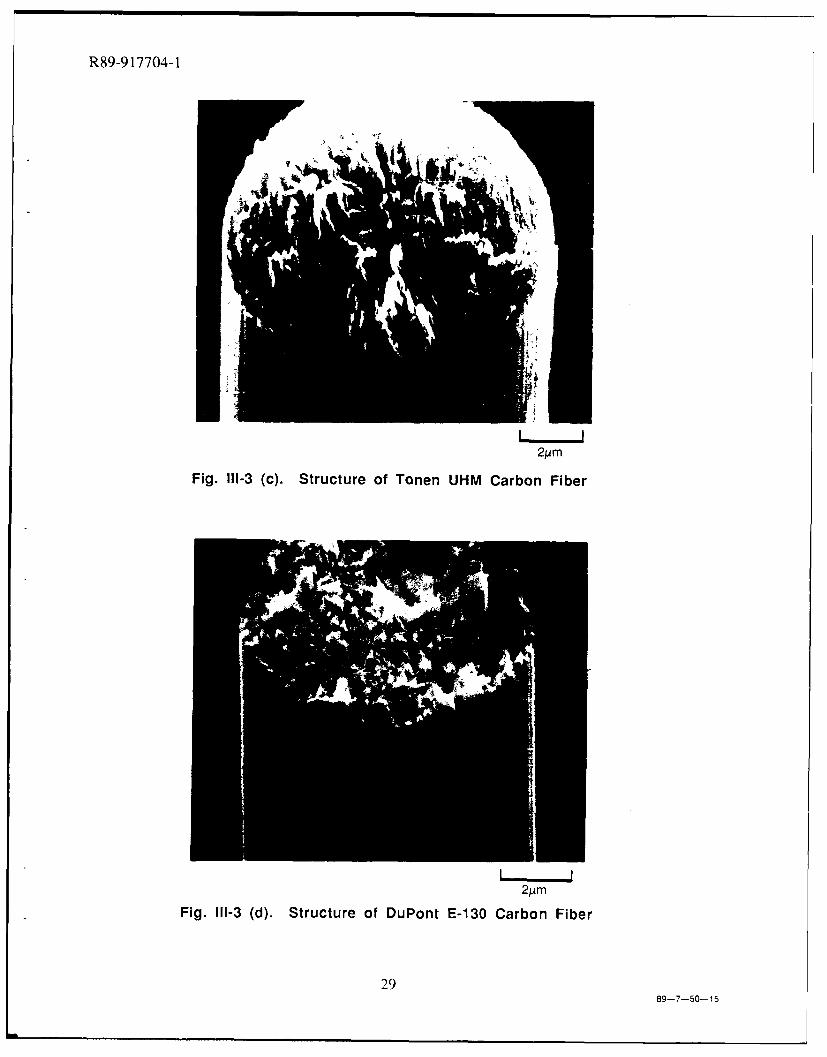
In contrast to HMU, the degree of graphitization displayed in ultra-high modulus pitch-derived fiber results in a highly oriented structure characterized by radial alignment of thegraphite planes about the fiber axis. Figures m-3(b), (c), and (d) illustrate the structures of P-100, UHM, and E-130 pitch-based carbon fibers, respectively. Like HMU fiber, the outer layerof pitch-based fiber also consists to some degree of graphite planes which are oriented parallel tothe fiber surface; however, a portion of the surface also consists of planes from the interior of thefiber whose edges intersect the outer fiber surface. These edge planes possess a very highsurface energy, consequently resulting in a surface chemistry that differs from that of HMUfiber. Another distinction between pitch-based and HMU fiber is the corrugated surface of thepitch-based fiber. This increase in surface roughness results in a higher specific surface area,which translates directly to increased interfacial area in composites reinforced with pitch-basedcarbon fiber.
C. 2. Tensile Stress-Strain Behavior
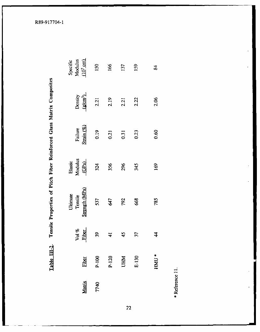
Borosilicate glass matrix composites unidirectionally reinforced with four different types ofultra-high modulus pitch-based carbon fiber were fabricated (see Table III-1 for specific fibersused). The tensile stress-strain behavior of all of the composites was very similar, with ultimatetensile strengths (UTS), elastic moduli, and failure strains as reported in Table 111-2. CompositeUTS values varied from 540-790 MPa, which is in part due to the differences in fiber volumeand fiber strength. These UTS values represent only 50-75% of the strength that would beexpected based on single fiber strengths and fiber volume; however, this amount of translation isconsistent with that displayed by other C/Glass composite systems (e.g., the UTS of theHMU/Glass composite listed in Table 111-2 represents 65% translation of fiber strength). Thereare a number of possible explanations for this lack of full translation, including damage to thefibers during fabrication or slight misalignment of the fibers in the tensile samples. In fact, it hasbeen shown that as little as 1 of misalignment, either through an error in layup or in machiningof the tensile samples from the composite coupon, can reduce measured strengths of carbon fiberreinforced polymers by more than 30% [17].
11
R89-917704-1
However, in this case misorientation is not believed to be the cause of the lower compositestrengths since the degree of strength translation from the fibers is fairly consistent among all thecomposites fabricated. A more likely explanation is that fiber bundle strength plays a moreimportant role in determining ultimate composite failure stress than does single fiber strength.Models employing this concept [18-21) consider the statistical nature of fiber strength, withcomposite failure resulting from an accumulation of single fiber breaks. As the weaker fibersfail, the load is carried by an increasingly fewer number of fibers, with the effective stress borneby these remaining fibers increasing as more fibers break. Intact fibers in the vicinity of a fiberbreak are subjected to a higher load intensity than those farther away from the fracture site. Alsoplaying a role is the "critical transfer length" (1c), or the ineffective length over which load cannotbe transferred after fiber failure. This accumulation of breaks usually leads to failure of thecomposite at loads below those predicted based on average single fiber strength; however, smallvalues of Ic can actually lead to higher composite strengths than those predicted based on singlefiber strength. This model has been successfully used to explain tensile behavior in Nicalonreinforced glass-ceramic composites [22]. More information on the bundle strengths of pitch-based carbon fibers is required before a similar analysis can be performed.
Composite elastic moduli were all in the range of 300-350 GPa, with correspondingspecific elastic moduli of 135-165 x 107 cm (refer to Table 111-2). These values are a significantincrease from those obtained using HMU fiber (Table II-2) and are in a range of values that canbe considered for use in the design of structural components for space systems. The elasticmoduli are near those predicted based on a "rule of mixtures" (ROM) approach. This differssomewhat from the behavior observed in C/Glass composites reinforced with HMU fiber, wherethe fiber appears to contribute only about 80% of its reported stiffness to the composite [10].This apparent loss in fiber stiffness could be caused by damage to the HMU fiber during tapefabrication, specifically in the sizing removal step. The oxidative stability of carbon fibers isknown to be directly proportional to fiber elastic modulus, which is a reflection of the degree ofgraphitization of the fiber structure. The lower degree of graphitization in HMU carbon fibermakes it inherently less oxidation resistant than ultra-high modulus pitch-based fiber, whichshould give the pitch-based fiber greater stability during bum-off of the sizing. If any materialwere removed from the fiber surface during sizing bum-off, it would be more detrimental to theperformance of HMU fiber than to that of ultra-high modulus pitch-based carbon fiber due to thestructural dissimilarities that exist between HMU fiber and pitch-based fiber (described earlier).As a result of these dissimilarities, most of the stiffness in HMU fiber is concentrated in the outerlayer, where the graphite basal planes are highly oriented parallel to the fiber surface, whereas inthe pitch-based carbon fiber the uniform internal structure results in constant stiffness across thefiber cross-section. Therefore, the removal of only a small percentage of the HMU fiber surfaceresults in a large decrease in fiber stiffness [16]. Pitch-based carbon fiber, on the other hand,can tolerate some surface removal with no sacrifice to fiber stiffness [23].
A tensile stress-strain curve representative of the characteristic behavior displayed by all the
12
R89-917704-1
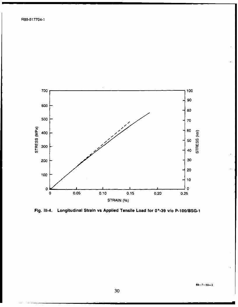
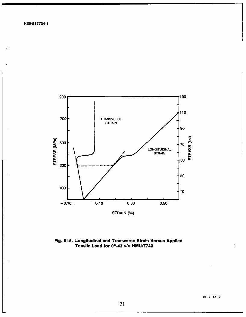
pitch fiber reinforced glasses is shown in Figure 111-4. This curve was obtained from acomposite containing approximately 40 vol% P-100 fiber. It is instructive to examine the tensilebehavior of the P-100/Glass composite by first comparing it with that displayed by the well-characterized HMU/Glass composite system [11]. Several characteristics are shared by the twotypes of composites, while others are quite dissimilar. Figure Ii-5 shows a typical stress-straincurve for a unidirectionally reinforced HMU/Glass composite containing approximately 40 vol%fiber. The composite displays linear elastic behavior up to a strain level of about 0.2%. In thisinitial linear region, the composite elastic modulus is predictable based on a combination ofstiffness from the carbon fibers and the glass matrix. At the upper level of this initial linearregion, the stress-strain curve deviates significantly from linearity, passing through a 'plateau'region of increasing strain with very little increase in stress. The point where the curve deviatesfrom linearity is commonly referred to as the proportional limit (PL). In the HMU/Glass
composite system, it has been assumed that the PL corresponds to the onset of matrixmicrocracking and probable fiber-matrix debonding [ 11 ]. In the plateau region, the degree ofmicrocracking of the matrix and fiber-matrix debonding increases rapidly, resulting in a large andsudden increase in transverse strain when the fiber tows 'broom out' (allowed by theconstraining force of the matrix being reduced through microcracking and debonding. Cyclictensile testing of this composite system has indicated that the matrix no longer contributes to theoverall composite stiffness once the composite has been strained past the plateau region [11]).The curve then again exhibits linear behavior representative of the fibers carrying the load aloneafter matrix microcracking. The mechanism of fiber-matrix debonding prior to this stage iscritical to the fibers being able to carry the load until they reach their inherent failure strain of 0.6to 0.7%. If significant debonding did not occur, matrix cracks would propagate directly throughthe fibers and the composite would fail in a brittle manner.
The tensile stress-strain behavior of the P-100/Glass composite shows some similarity to
the HMU/Glass composite, but also differs in several ways. The initial portion of the curve isagain representative of linear elastic behavior which is predictable based on a knowledge of fiberand matrix moduli. The curve experiences a PL at a strain of about 0.05%, followed by asecondary region of steadily decreasing slope. The fibers continue to carry the load until theyreach their failure strain of approximately 0.2%. The stress-strain curves of the two materials
differ in two main respects: 1) the P-100/Glass composite does not exhibit the 'plateau' regionfollowing the PL, and; 2) the secondary region representative of fibers carrying the load alone inthe P- 100/Glass composite is not linear, but instead exhibits a negative curvature with increasingstrain. These dissimilarities between the two composite systems most likely result from anumber of factors, including a variation in the nature of the fiber-matrix interface caused by thediffering surface structure and surface chemistry of HMU and P- 100 carbon fiber.
It does not appear that the PL in the P-i 00/Glass composite is simply the result of the
matrix no longer contributing to the overall composite stiffness. This was assessed by
13
R89-917704-1
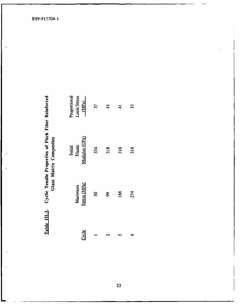
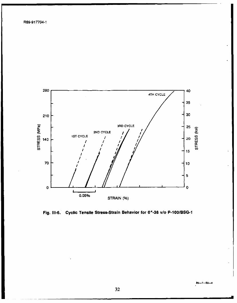
comparing the theoretical matrix contribution to composite stiffness with the difference betweenthe slope of the initial linear region of the curve (EI) and the modulus corresponding to the initialportion of the secondary region of the curve (E2); viz., that portion of the curve immediatelyfollowing the PL. This value of E, - E2 is equal to about 30 GPa for the P-100/Glass composite,which is very close to the value of 38 GPa corresponding to the contribution of the matrix tocomposite stiffness. However, cyclic tensile testing of this system gives indications that themechanism by which this transient loss in stiffness occurs in the P-100/Glass composite isdifferent from that in the HMU/Glass composite, i.e. it does not appear that the matrixexperiences severe microcracking at the PL in the P-100/Glass composite. Figure 11I-6 showsthe stress-strain curves for one of the cyclic tensile tests performed on the P-100/Glasscomposite, with the tensile data summarized in Table I11-3. During the first cycle, the compositewas loaded just past the PL to a stress of 50 MPa, with the composite exhibiting an initial elasticmodulus of 334 GPa. On unloading, the curve traced over the loading curve exactly, with nopermanent strain being introduced. The second cycle resulted in the composite being loaded wellpast the PL to a stress of 99 MPa. The initial elastic modulus was slightly lower for the secondcycle (318 GPa), which may indicate some permanent loss of the matrix contribution to stiffness;however, the amount lost (16 GPa) represents only 40% of the total matrix contribution, i.e. thematrix still possesses 60% of its stiffness. During the third cycle, the composite experienced astress up to 166 MPa (significantly beyond the PL), and on unloading exhibited a permanentstrain of 0.004%. The initial elastic modulus during this cycle was again 318 GPa, indicating nofurther loss in matrix contribution from the loading of the second cycle. The fourth and finalcycle loaded the composite to the point of ultimate failure, with the initial elastic modulus againbeing 318 GPa.
This cyclic behavior differs from that of HMU/Glass composites in two significantrespects: 1) the P-100/Glass composite system exhibits a proportional limit during cyclessubsequent to those in which the loading exceeded the PL by a significant amount, and; 2) theinitial elastic modulus demonstrated in these cycles remains fairly constant and is indicative of thematrix contributing more than 50% of its stiffness to the composite. These two factors imply thatthe matrix in P-100/Glass composites does not experience the severe microcracking at the PL asit does in the HMU/Glass composite system. This seems reasonable in light of the fact that thelevel of strain where the PL occurs in HMU/Glass composites (- 0.20%) is well above the PLstrain in P-100/Glass composites (0.05%). In fact, the PL strain for HMU/Glass composites isat or above the failure strain regime of P-100/Glass composites, indicating that severe matrixmicrocracking may occur in the P-100/Glass composite system only on ultimate failure of thecomposite. This behavior is important when considering the possibility of designing structuralcomponents from P-100/Glass composites. Normally, the PL is considered to be the maximumstress to which a structure can be loaded in order for it to retain its properties during subsequentcycles. The repetitive tensile nature of the P-100/Glass composite system after being loaded wellpast the PL would seem to relax this criterion. Further analysis is underway to determine the
14
R89-917704-1
mechanism(s) responsible for the PL in the P-100/Glass composite system.
C. 3. Flexural Behavior
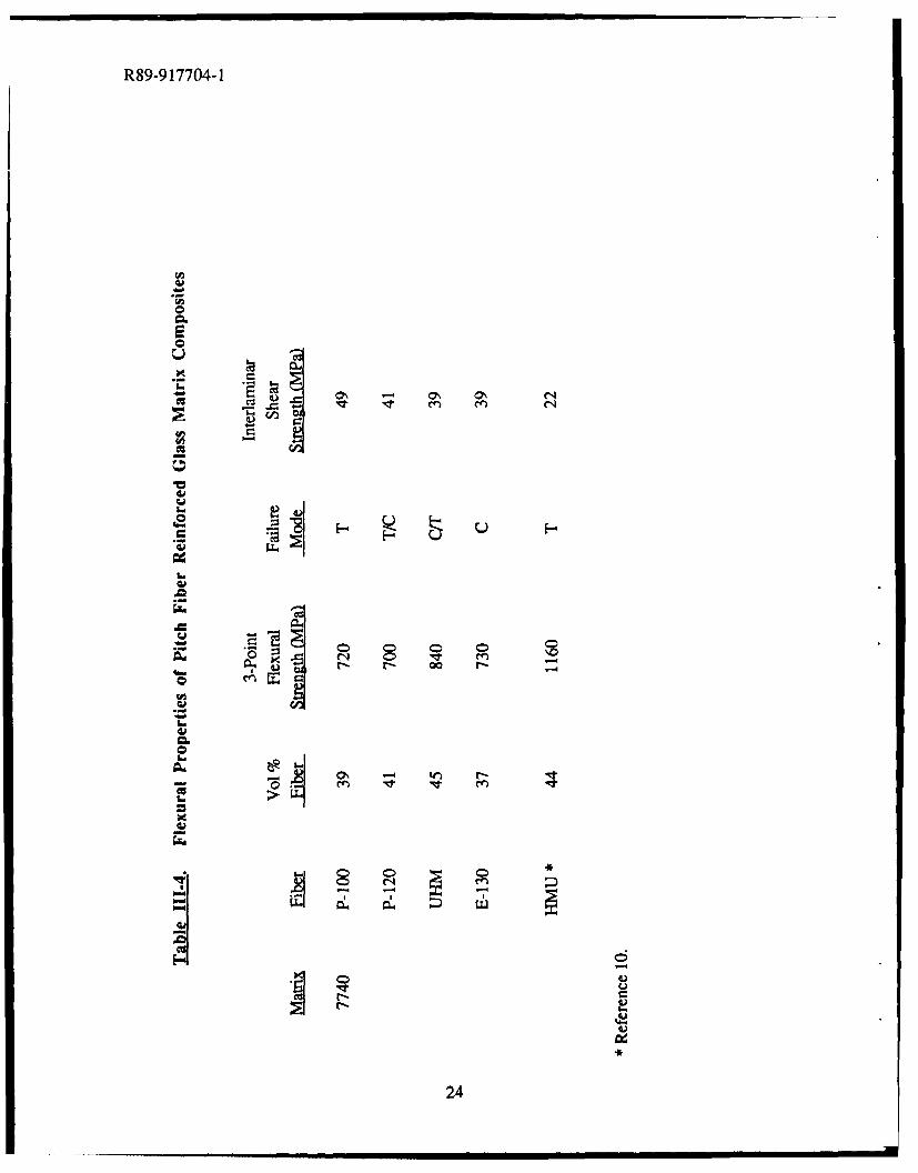
Three-point flexural testing was performed on all the C/Glass composites reinforced withpitch-based carbon fiber, with the results presented in Table 11I-4. The span-to-depth ratio wasin all cases greater than 23, since it has been reported that span-to-depth ratios less than 20 leadto a shear mode of failure [10, 24]. All of the flexural strengths were in the range of 700-840MPa, with corresponding Flexural Strength:Tensile Strength (FS:TS) ratios falling between 1.1and 1.3. This is in contrast to the HMU/Glass composite system, which typically exhibits muchhigher flexural strengths (refer to Table 111-4) and greater FS:TS ratios, usually around 2 (as inthe example given in Table 111-4). Most of the pitch fiber reinforced composites exhibitedprimarily a tensile failure mode, with little evidence of shear failure, although the compositesamples reinforced with E-130 fiber failed in compression. Some composite samples exhibitedmixed failure modes of both tension and compression.
Composite interlaminar shear strength (ILSS) values were obtained via short beam sheartesting. Span-to-depth ratios were held constant at a value of 4 so that all the composite samplesfailed in shear. The values of ILSS for all of the pitch fiber reinforced composites as well as thatfor an HMU/Glass composite are included in Table III-4. Shear strengths for the compositesreinforced with pitch-based fiber were in the range of 40-50 MPa, while that for the HMU/Glasscomposite was considerably less at 22 MPa. It has been shown [10] that short beam shearstrength in C/Glass composites is directly related to fiber-matrix interfacial debond shearstrength, ;n. (this value represents the shear stress necessary to initiate debonding between fiberand matrix). The average maximum interfacial shear stress (tm x) in HMU/Glass composites hasbeen found to be approximately 10 MPa using a fiber push-test technique [25]. While values oftmx have not been obtained for the composites containing pitch-based fiber via a directmeasurement (e.g. a fiber push test), it may be inferred based on the aforementionedrelationship between ILSS and tm that fiber-matrix interfacial adhesion is greater in compositesreinforced with pitch-derived carbon fibers than in HMU/Glass composites.
The increased fiber-matrix adhesion exhibited in the Pitch/Glass composites is most likelydue in part to increased mechanical interlocking created by the corrugated surface of the pitch-based carbon fibers (as described previously). The corrugated surface translates directly to anincrease in fiber-matrix interfacial area, as illustrated in Figure I-3(b). In this micrograph of afracture surface in a P-100/Glass composite, the matrix surrounding the "holes" where fibershave pulled out has replicated the corrugated surface of the pitch-based carbon fiber. It seemsclear that the mechanical interlocking of this type of interface would be greater than that of the"smooth" interface existing in HMU/Glass composites. Another factor that may contributepartially to the increased fiber-matrix adhesion in Pitch/Glass composites is the inherently higher
15
R 89-917704-1
wettability of the glass on the pitch-based carbon fibers compared to HMU fiber. Micro-sessiledrop experiments have shown that the contact angle between the borosilicate glass used in thisstudy and P-100 fiber is significantly less than that between the glass and HMU fiber [26],demonstrating that the glass wets the P-100 fiber more easily. It can be assumed that similarbehavior would exist with the other two pitch-based fibers used in this investigation. Although itseems reasonablc that increased wettability leads to greater values of interfacial adhesion, a directrelationship between the two has not yet been demonstrated. Work is currently underway toverify this relationship. Reasons for the increased wettability of pitch-based fibers arespeculative at this point. However, it is believed that two of the most probable causes are: (1)the rougher surface of the pitch-based fibers makes it easier for the glass to spread by providingmore surface sites, and; (2) the surface energy of the pitch-based carbon fibers is higher than thatof HMU fiber due to differences in the internal fiber structure (described previously).
The observed differences in ILSS and fiber-matrix adhesion in HMU/Glass composites andPitch/Glass composites can be used to explain the difference between the FS:TS ratio in thesetwo composite systems. During flexural testing of a composite in the HMU/Glass system, therelatively low values of ILSS and tm, allow the load to be redistributed throughout the samplevia shear deflection of the laminae relative to one another, thus allowing the composite to carryhigher loads and fail at a higher level of stress. On the other hand, the higher values of ILSS and
Tmax in the Pitch/Glass composite system make it more difficult for the load to be redistributed ina similar manner. This prevents the composite from carrying higher loads and results in failure atlower stress levels. Failure in these pitch-based fiber reinforced composites occurs once thetensile strength of the composite has been exceeded by a small amount, as evidenced by theFS:TS ratio of 1.1-1.3.
C. 4. Composite Fracture Behavior
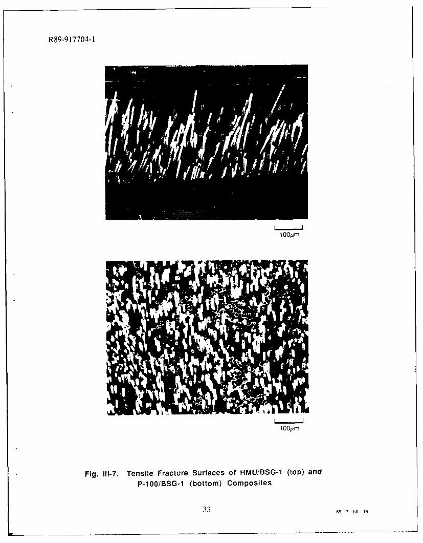
Tensile fracture surfaces of composites in the HMU/Glass and P-100/Glass systems areillustrated in Figure 11-7. The average fiber pullout length, If, is noticeably higher in theHMU/Glass composite than in the P-100/Glass composite. The well-known equation relatingcritical transfer length (1c) to fiber radius (R), fiber strength (Of), and interfacial shear stress (-),given as [271
RoflC=
't (Ili-4)
can be applied to these cases if it is assumed that the fiber pullout length If is equal to the criticaltransfer length. This is a reasonable assumption for the purposes of this discussion. Byinserting the values of R and of for HMU and P- 100 fiber given in Table li,- 1L, it can be seen that
16
R89-917704-1
for comparison between these two systems, equation 11-4 simplifies approximately to
'f.HI-MU _" P-100
if, P-100 HM (111-5)
Equation 111-5 indicates that the ratio of fiber pullout lengths in these two composite systems isapproximately equal to the inverse ratio of fiber-matrix interfacial shear strengths, implying that'tp.(0 is significantly greater than HMU. This is in agreement with the results presented earlierrelating Trn. to ILSS, where the short beam shear strength of Pitch/Glass composites was foundto be about twice that of HMU/Glass composites.
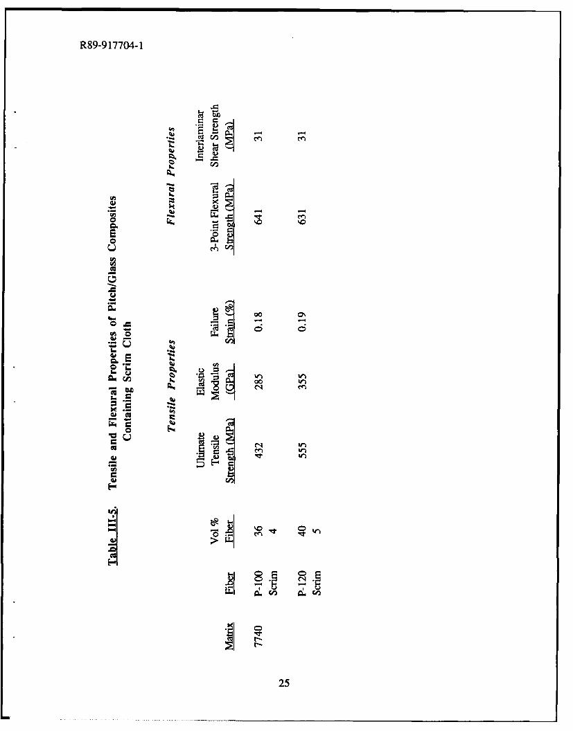
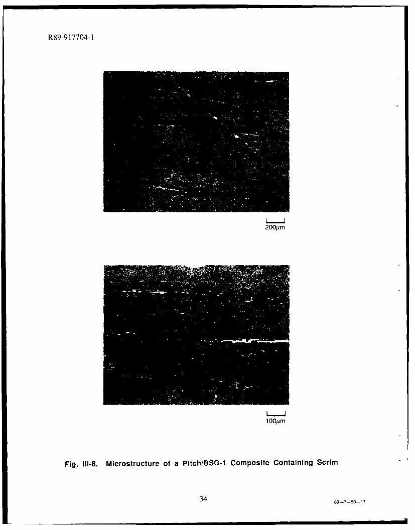
Flexural fracture behavior followed a similar trend to the tensile fracture behavior, with thePitch/Glass composites exhibiting much shorter fiber pullout lengths than the HMU/Glasscomposite. As above, this was expected based on the relative magnitudes of rmax in the twocomposite systems. These short pullout lengths were of some concern, since the work offracture and the associated composite toughness are directly related to If. In an attempt toengineer additional toughness into Pitch/Glass composites, a"microstructural toughening"approach was adopted. This approach involved the addition of a thin layer of carbon "scrimcloth" between laminae in the composite. The presence of the scrim cloth provides a glass-richregion between plies, as shown in Figure 11-8. These glass-rich regions lower the ILSS of thecomposite by providing an easy path for shear deflection of advancing cracks. Results of tensileand flexural testing of Pitch/Glass composites containing scrim cloth are summarized in Tablern-5. Tensile and flexural strengths are somewhat lower in the composites containing scrimwhen compared against the data in Tables 11I-4 and rn1-5. However, when taking into accountthe decrease in load-bearing cross-section in the composites containing scrim (assuming that thescrim cloth bears very little of the total load), the effective strengths of the axial plys of thecomposites with and without scrim are similar.
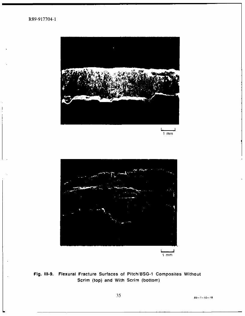
The property that shows a real change is the ILSS, which experienced a 25-35% decreasein the composites containing scrim. This decrease in ILSS had very little effect on the tensilefracture behavior of the scrim-containing composites. To the contrary, however, the flexuralfracture behavior was significantly affected, as shown in Figure 111-9. In the standardPitch/Glass composite, the crack that initiated on the tensile surface propagated about midwaythrough the composite, deflected once between laminae, and then ran through the remainder ofthe composite thickness. On the other hand, the composite containing scrim exhibited a muchmore tortuous path for the crack during propagation through the composite. After initiation onthe tensile surface, the crack experienced a shear deflection at each successive layer of scrim thatit encountered. This more graceful mode of failure resulted in an increase in the area under theload-deflection curve, translating to an increase in the work of fracture for the composites
17
R89-917704-1
containing scrim.
D. Summary
Glass matrix composites possessing higher specific stiffness were successfully fabricatedutilizing ultra-high modulus pitch-based carbon fibers. Elastic stiffnesses obtained in thesePitch/Glass composites were predictably high; however, only 50-75% translation of fiberstrength was demonstrated. This behavior is similar to other C/Glass composite systems and isbelieved to be related to the control of fiber bundle strength over composite strength. The tensilestress-strain behavior of Pitch/Glass composites was found to differ in several respects to that ofthe well-characterized HMU/Glass composite system. The cyclic stress-strain behavior wasespecially interesting when considering the repetitive nature of the stress-strain curve afterloaiding well past the proportional limit. Composite interlaminar shear strength and fiber-matrix
interfacial shear strength (Tma) were found to be significantly higher in Pitch/Glass compositesthan in HMU/Glass composites, with subsequent effects on fiber pullout length and fracture
behavior. The increase in tmax is caused by differences in fiber surface structure and surfacechemistry. Work of fracture during flexure of Pitch/Glass composites was improved byintroducing a layer of carbon scrim cloth between plies, which lowered interlaminar shearstrength without significantly affecting composite strength and stiffness.
ACKNOWLEDGEMENTS
The authors gratefully acknowledge the support of the Innovative Science and Technologybranch of the Strategic Defense Initiative Organization through the Office of Naval Research(Contract N00014-85-C-0332) with Dr. Steven Fishman as contract monitor. They would alsolike to recognize Mr. William Kelley for composite fabrication, Ms. Judy Whitehead for carryingout for the SEM portions of the investigation, and the Mechanical Testing group at UTRC forperforming the tensile and flexural testing.
REFERENCES
1. R. A. J. Sambell, D. H. Bowen and D. C. Phillips, "Carbon Fibre Composites WithCeramic and Glass Matrices - Part 1. Discontinuous Fibres," J. Mater. Sci., 7 (1972) 663-675.
2. R. A. J. Sambell, et al., "Carbon Fibre Composites With Ceramic and Glass Matrices - Part2. Continuous Fibres," J. Mater. Sci., 7 (1972) 676-681.
3. D. C. Phillips, R. A. J. Sambell and D. H. Bowen, "The Mechanical Properties of CarbonFibre Reinforced Pyrex Glass," J. Mater. Sci., 7 (1972) 1454-1464.
18
R89-917704-1
4. D. C. Phillips, "Interfacial Bonding and the Toughness of Carbon Fibre Reinforced Glassand Glass-Ceramics," J. Mater. Sci., 9 (1974) 1847-1854.
5. K. M. Prewo and J. F. Bacon, "Glass Matrix Composites - I - Graphite Fiber ReinforcedGlass," Proceedings of ICCM/2 - The 1978 International Conference on Composite Materials,Toronto, Canada, 1978, pp. 64-74.
6. K. M. Prewo, J. F. Bacon and D. L. Dicus, "Graphite Fiber Reinforced Glass MatrixComposites," SAMPE Quart., 10 (1979) 42.
7. K. M. Prewo, "A Compliant, High Failure Strain, Fibre-Reinforced Glass-MatrixComposite," J. Mater. Sci., 17 (1982) 3549-3563.
8. K. M. Prewo and E. J. Minford, "Graphite Fiber Reinforced Thermoplastic Glass MatrixComposites for Use at 10000F," SAMPE J., (1985) 26-33.
9. K. M. Prewo and J. A. Batt, "The Oxidative Stability of Carbon Fibre Reinforced Glass-Matrix Composites," J. Mater. Sci., 23 (1988) 523-527.
10. K. M. Prewo, "Carbon Fibre Reinforced Glass Matrix Composite Tension and FlexureProperties," J. Mater. Sci., 23 (1988) 2745-2752.
11. V. C. Nardone and K. M. Prewo, "Tensile Performance of Carbon-Fibre-ReinforcedGlass," J. Mater. Sci., 23 (1988) 168-180.
12. V. C. Nardone, et al., "Carbon Fiber Reinforced Metal and Glass Matrix Composites forSpace Based Applications," presented at the 19th International SAMPE Technical Conference,Arlington, Virginia, October 13-15, 1987 (sponsored by SAMPE).
13. W. K. Tredway and K. M. Prewo, "Performance of Glass Matrix Composites ReinforcedWith PAN and Pitch-Derived Carbon Fibers," presented at the 13th Annual Conference onComposite Materials and Structures, Cocoa Beach, Florida, January 18-20, 1989 (sponsored byUnited States Advanced Ceramics Association).
14. W. Johnson, "The Structure of PAN Based Carbon Fibres and Relationship to PhysicalProperties"; pp. 389-473 in Handbook of Composites. Volume 1 - Strong Fibres. Edited by W.Watt and B. V. Perov. Elsevier Science Publishers B. V., Amsterdam, 1985.
15. B. Rand, "Carbon Fibres from Mesophase Pitch"; pp. 495-575 in Handbook ofComposites. Volume 1 - Strong Fibres. Edited by W. Watt and B. V. Perov. Elsevier SciencePublishers B. V., Amsterdam, 1985.
19
R89-917704-1
16. K. J. Chen and R. J. Diefendorf, "Residual Stresses in High Modulus Carbon Fibers,"
Proceedings of Progress in Science and Engineering of Composites. ICCM-IV, Tokyo, Japan,1982, pp. 97-105.
17. P. W. Manders and I. M. Kowalski, "The Effect of Small Angular Fiber Misalignments andTabbing Techniques on the Tensile Strength of Carbon Fiber Composites," Proceedings of32nd International SAMPE Symposium, 1987, pp. 985-996.
18. B. W. Rosen, "Tensile Failure of Fibrous Composites," AIAA J., 2 (1964) 1985-1991.
19. B. W. Rosen, "Mechanics of Composite Strengthening"; pp. 37-75 in Fiber CompositeMaterials. American Society for Metals, Metals Park, Ohio, 1965.
20. C. Zweben, "Tensile Failure of Fiber Composites," AIAA J., 6 (1968) 2325-2331.
21. C. Zweben and B. W. Rosen, "A Statistical Theory of Material Strength With Application toComposite Materials," J. Mech. Phys. Solids, 18 (1970) 189-206.
22. K. M. Prewo, "Tension and Flexural Strength of Silicon Carbide Fibre-Reinforced GlassCeramics," J. Mater. Sci., 21 (1986) 3590-3600.
23. M. Aoki, Tonen Energy International Corp., 1989, personal communication.
24. K. M. Prewo and V. C. Nardone, "Carbon Fiber Reinforced Glass Matrix Composites forSpace Based Applications," UTRC Report R86-917161-1, ONR Annual Report, September 15,1986.
25. D. H. Grande, J. F. Mandell and K. C. C. Hong, "Fibre-Matrix Bond Strength Studies ofGlass, Ceramic, and Metal Matrix Composites," J. Mater. Sci., 23 (1988) 311-328.
26. C. G. Pantano, G. Chen and D. Qi, "Interface Reactions and Wetting in Carbon FiberReinforced Glass Matrix Composites," submitted for publication, 1989.
27. A. Kelly, "Microstructural Parameters of an Aligned Fibrous Composite," The Propertiesof Fibre Composites, National Physical Laboratory, 1971, pp. 5-14.
20
R89-917704-1
Table lII-I
Materials Used in Composite Fabrication
FIBERS
Elastic TensileDensity Modulus Strength Fiber Dia.
Fibe Manufacturer g Lc (LPa) (MPI) (in) Precurso
HMU Hercules 1.84 380 2760 8 PAN
UHM Tonen 2.15 682 3410 10 PitchP-100 Amoco 2.16 758 2240 10 PitchP- 120 Amoco 2.17 827 2067 10 Pitch
E-130-X DuPont 2.19 894 3445 9.2 Pitch
MATRIX COMPOSITION
Elastic Glass TransitionMatrix Density Modulus Temperature CITE
Designation .g/c_ (GPa) (0C0 (2pmC)
BSG-1* 2.23 63 560 3.2
• BSG = borosilicate glass
21
R89-9 17704-1
ItIE ~ o00
I-C I
0n04.4
ew
L
(". co 0.
Aw
4.-n
>oi
U, r- ~ - ~ 0
ME. '.
02
R89-9 17704-1
00 00 00
- e'
23
R89-9 17704-1
W,
'tUn,0c
L)F-
2TA
x mt4.- 00 - -
4.~24
R89-917704-1
a..
" --
E
tv
go0L,
W4 c
4.25
R89-917704-1
SUPPLY SPOOL SLURRY
TAKE-UP DRUM
BURNOUT STACK ;7CUT
LOAD ANDPRESS
Fig. I1-1. Composite Fabrication Procedure
89--7-50-1
26
R89-91 7704-1
THREE POINT FLEXURE TENSILE TEST
Fig. 111-2. Mechanical Test Techniques
89-7-50-2
27
R89-9 17704-1
5pm
Fig. 111-3 (a). Structure of Hercules HMU Carbon Fiber
5pm
Fig. 111-3 (b). Structure of Amoco P-100 Carbon Fiber
28 89-7-50-14
R89-9 17704-1
2pm
Fig. 111-3 (c). Structure of Tonen UHM Carbon Fiber
Fig. 111-3 (d). Structure of DuPont E-130 Carbon Fiber
2989-7-50--15
R89-91 7704-1
700 1100
90600
80
500 70
CL 400 - 60
Cl)-50 )
q:300 ccI-~ 40 ICI)n
200 -30
-20100
-10
0 00 0.05 0.10 0.15 0.20 0.25
STRAIN (f)
Fig. 111-4. Longitudinal Strain vs Applied Tensile Load for 00-39 vlo P-100/BSG-1
89--7-50-3
30
R89-917704-1
900 130
110
700 TRANSVERSESTRAIN
90
U)0 500- -1-70(./) l LONGITUDINAL 03Ul) / STRAIN -
1--50 u)un 300 .
30
100-10
-0.10 0.10 0.30 0.50
STRAIN (%)
Fig. 111-5. Longitudinal and Transverse Strain Versus AppliedTensile Load for 0-43 vio HMU/7740
86-7-54-3
31
R89-91 7704-1
280 404TH CYCLE
-35
210 -30
3RD CYCLE -25a.2ND CYCLE -
Cl) ST CYCLE / 0U)- 20
Cw140 / /
15/ 15
70 /10
5
0 L0
0.05% STRAIN (%)
Fig. 111-6. Cyclic Tensile Stress-Strain Behavior for 0*-38 via P-100/BSG-1
89-7-50-4
32
R89-9 17704-1
1 OOPim
Fig. 111-7. Tensile Fracture Surfaces of HMU/BSG-1 (top) andP-100/BSG-1 (bottom) Composites
33 89-7-50-16
R89-9 17704-1
200M~m
1OJM
Fig. 111-8. Microstructure of a Pltch/BSG-1 Composite Containing Scrim
34 89-7-50-17
R89-9 17704-1
1 MM
1mm
Fig. 111-9. Flexural Fracture Surfaces of Pitch/BSG-1 Composites WithoutScrim (top) and With Scrim (bottom)
3589-7-50-18
R89-917704-1
IV. IMPROVED MECHANICAL BEHAVIOR IN PITCH FIBER REINFORCEDGLASS MATRIX COMPOSITES THROUGH MATRIX MODIFICATION
The previous chapter discussed the tensile and flexural behavior of glass matrix compositesreinforced with pitch-based carbon fiber where the matrix was the BSG- 1 composition. Whilethese composites demonstrated respectable levels of strength and stiffness, the proportional limit(PL) stress and strain values were somewhat low, with PL stresses of -100 MPa and PL strainsof 0.03-0.04%. These PL values represent less than 20% of the ultimate composite tensile stressand failure strain, which can be of great concern from a design standpoint. This chaptersummarizes work conducted to improve PL behavior in Pitch/Glass composites by makingmodifications to matrix composition that result in less residual tensile stress in the matrix aftercomposite fabrication.
A. Residual Stresses in Carbon Fiber Reinforced Glass Matrix Composites
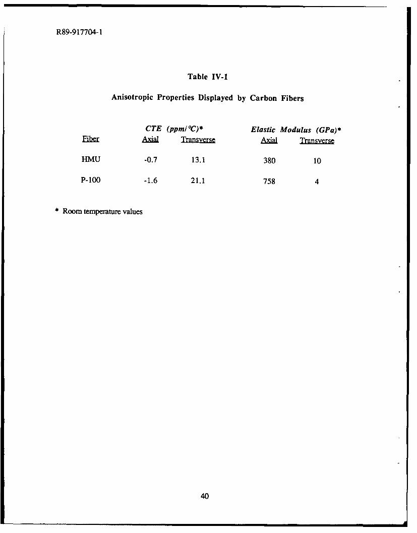
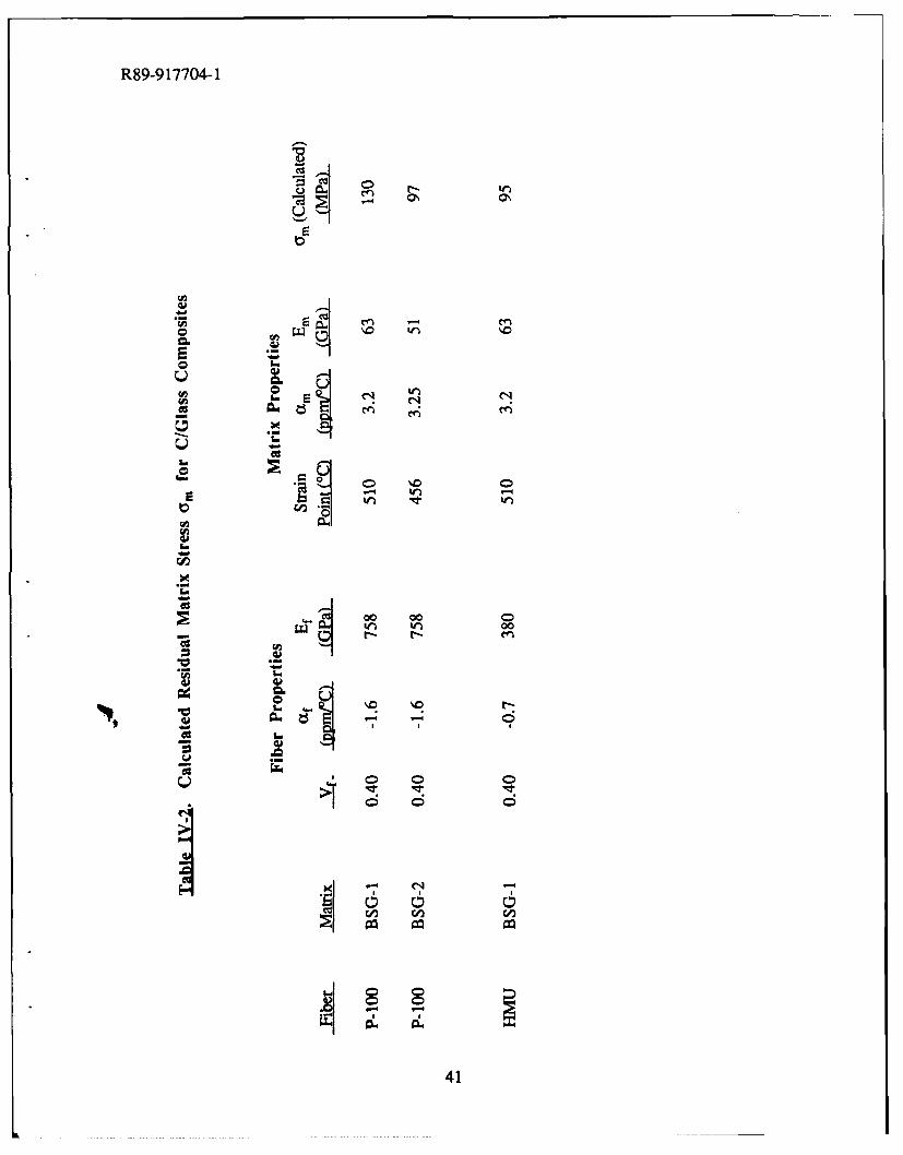
Carbon fiber reinforced glass matrix (C/Glass) composites are characterized by a complexstress state as a result of coefficient of thermal expansion (CTE) mismatch between the carbonfiber and the glass matrix. Complicating the matter even further is the highly anisotropic natureof carbon fiber. This large degree of anisotropy in the axial and transverse fiber directionsresults from the graphitic microcrystalline structure of the fiber (for a more complete discussionof carbon fiber structure, refer to section III. C. 1.). Examples of properties that vary greatly inthe two directions are CTE and elastic modulus, as summarized in Table IV-1 for HMU and P-100 fibers. The negative CTE of the fiber and the positive CTE of the glass results in the matrixbeing placed in residual tension in a direction parallel to the fibers. The magnitude of the tensile
stress is determined by several factors other than the difference in CTE (Aa) between fiber andmatrix, including the fiber and matrix volume fractions, fiber and matrix moduli, and viscositycharacteristics of the glass. The viscosity characteristic that is most important is the straintemperature (or strain point) of the glass, which is defined as the temperature below which theviscosity is so high that any further strain can be removed only after several hours at or abovethat temperature [1]. As the composite begins to cool from the fabrication temperature, theviscosity of the glass is low enough that the matrix can relax and relieve any accumulated stressuntil it reaches the strain temperature. After that, relaxation cannot occur and stress builds up asthe composite continues to cool to room temperature.
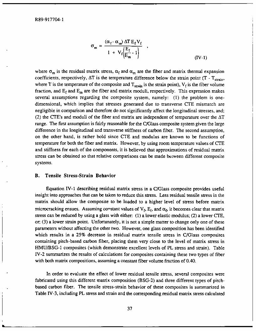
The residual matrix stress existing at any temperature below the strain point can becalculated using a simple expression relating fiber and matrix CTE, fiber and matrix moduli, fibervolume fraction, and the change in temperature below the strain point. This expression can begiven as
36
R89-917704-1
(a f- tCc) AT EfVf
1 + Vf I- m
where am is the residual matrix stress, ctf and a m are the fiber and matrix thermal expansioncoefficients, respectively, AT is the temperature difference below the strain point (T - Tstain,where T is the temperature of the composite and T.t,.in is the strain point), Vf is the fiber volumefraction, and Ef and Em are the fiber and matrix moduli, respectively. This expression makesseveral assumptions regarding the composite system, namely: (1) the problem is one-dimensional, which implies that stresses generated due to transverse CTE mismatch arenegligible in comparison and therefore do not significantly affect the longitudinal stresses, and;(2) the CTE's and moduli of the fiber and matrix are independent of temperature over the ATrange. The first assumption is fairly reasonable for the C/Glass composite system given the largedifference in the longitudinal and transverse stiffness of carbon fiber. The second assumption,on the other hand, is rather bold since CTE and modulus are known to be functions oftemperature for both the fiber and matrix. However, by using room temperature values of CTEand stiffness for each of the components, it is believed that approximations of residual matrixstress can be obtained so that relative comparisons can be made between different compositesystems.
B. Tensile Stress-Strain Behavior
Equation IV-1 describing residual matrix stress in a C/Glass composite provides usefulinsight into approaches that can be taken to reduce this stress. Less residual tensile stress in thematrix should allow the composite to be loaded to a higher level of stress before matrix
microcracking ensues. Assuming co-stant values of Vf, Ef, and af, it becomes clear that matrixstress can be reduced by using a glass with either: (1) a lower elastic modulus; (2) a lower CTE,or, (3) a lower strain point. Unfortunately, it is not a simple matter to change only one of theseparameters without affecting the other two. However, one glass composition has been identifiedwhich results in a 25% decrease in residual matrix tensile stress in C/Glass compositescontaining pitch-based carbon fiber, placing them very close to the level of matrix stress inHMU/BSG-1 composites (which demonstrate excellent levels of PL stress and strain). TableIV-2 summarizes the results of calculations for composites containing these two types of fiberwith both matrix compositions, assuming a constant fiber volume fraction of 0.40.
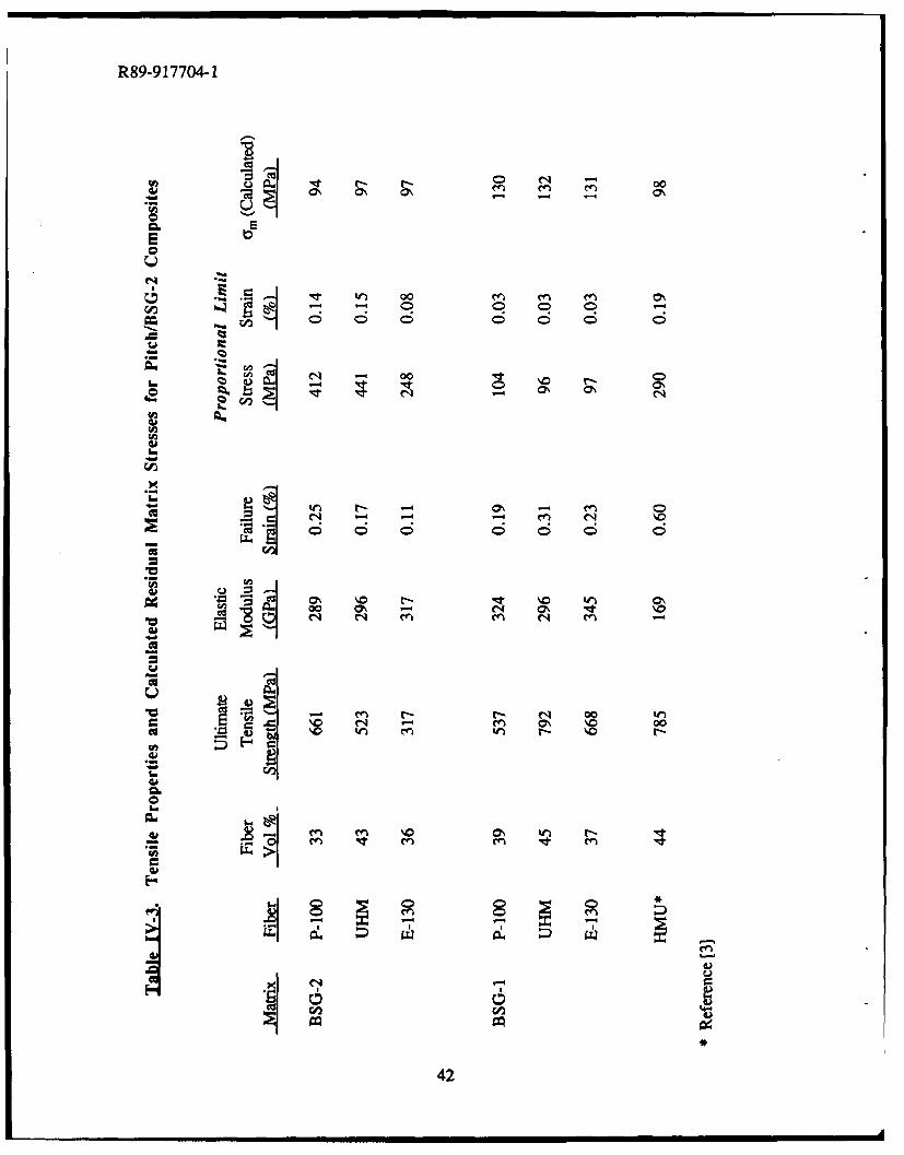
In order to evaluate the effect of lower residual tensile stress, several composites werefabricated using this different matrix composition (BSG-2) and three different types of pitch-based carbon fiber. The tensile stress-strain behavior of these composites is summarized inTable IV-3, including PL stress and strain and the corresponding residual matrix stress calculated
37
R89-917704-1
for each composite. Also included in the table for comparison are data for the composites
fabricated using BSG-1 as the matrix (presented in Chapter 111) and a composite in theHMU/BSG-1 system. The moduli of the Pitch/BSG-2 composites correspond closely to thosepredicted based on the rule of mixtures. Composite strengths are respectable for the compositescontaining P-100 and UHM fiber; however, the composite reinforced with E-130 fiber exhibited
a rather low tensile strength. The reason for this low strength is unclear. Comparison of PLstresses and strains between the two matrix compositions reveals an outstanding increase in theseparameters, even in the low-strength E-130/BSG-2 composite. This increase in PL stress andstrain correlates well with the reduction in residual matrix stress resulting from the use of theBSG-2 matrix composition.
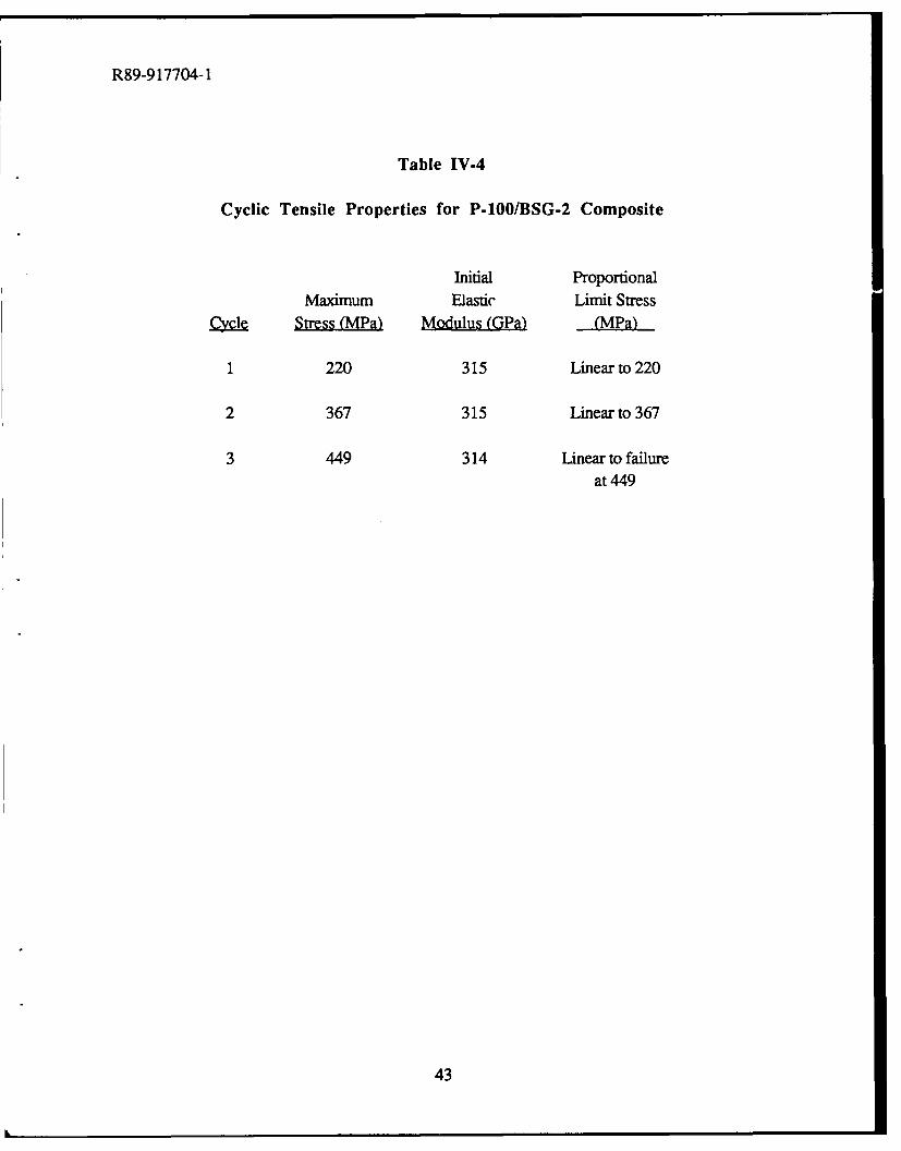
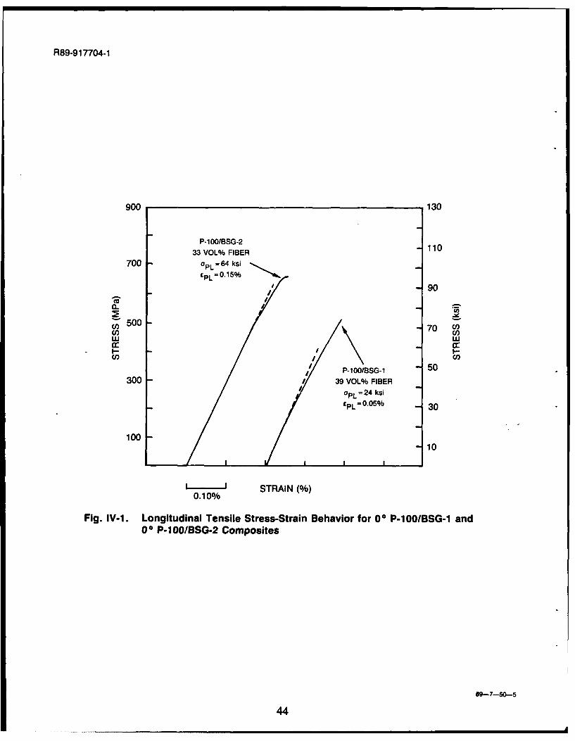
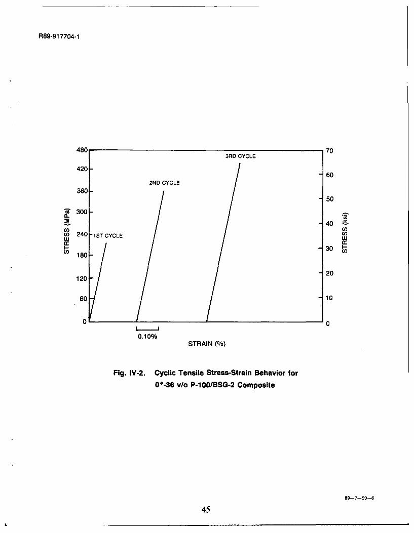
The stress-strain curves of P-100/BSG-2 and P-100/BSG-1 composites are compared inFigure IV- 1. While the general shape of the curves is similar, it is clear that the linear portion ofthe curve (up to the PL) is much larger in the P-IOOIBSG-2 composite. Cyclic tensile testing of aP-100/BSG-2 composite was performed to assess the effect of repeated loading to successivelyhigher stresses on the stress-strain behavior. The cyclic stress-strain curves are shown in FigureIV-2, with the results being summarized in Table IV-4. During the first cycle, the composite wasloaded to a maximum stress of 220 MPa, with an initial elastic modulus of 315 GPa, and
demonstrated linear behavior throughout the entire range. No permanent strain was introducedon the unloading portion of the cycle. In the subsequent second and third cycles, during whichthe maximum loads were 367 and 449 MPa, respectively, the composite also exhibited linearbehavior and an elastic modulus of 315 GPa. No proportional limit was observed up to a stressof 449 MPa, where failure occurred at the doublers. The repetitive nature of the elastic modulusand the lack of a PL confirmed that there was no damage accumulation in the matrix, indicatingthat matrix microcracking was not taking place during loading of the composite.
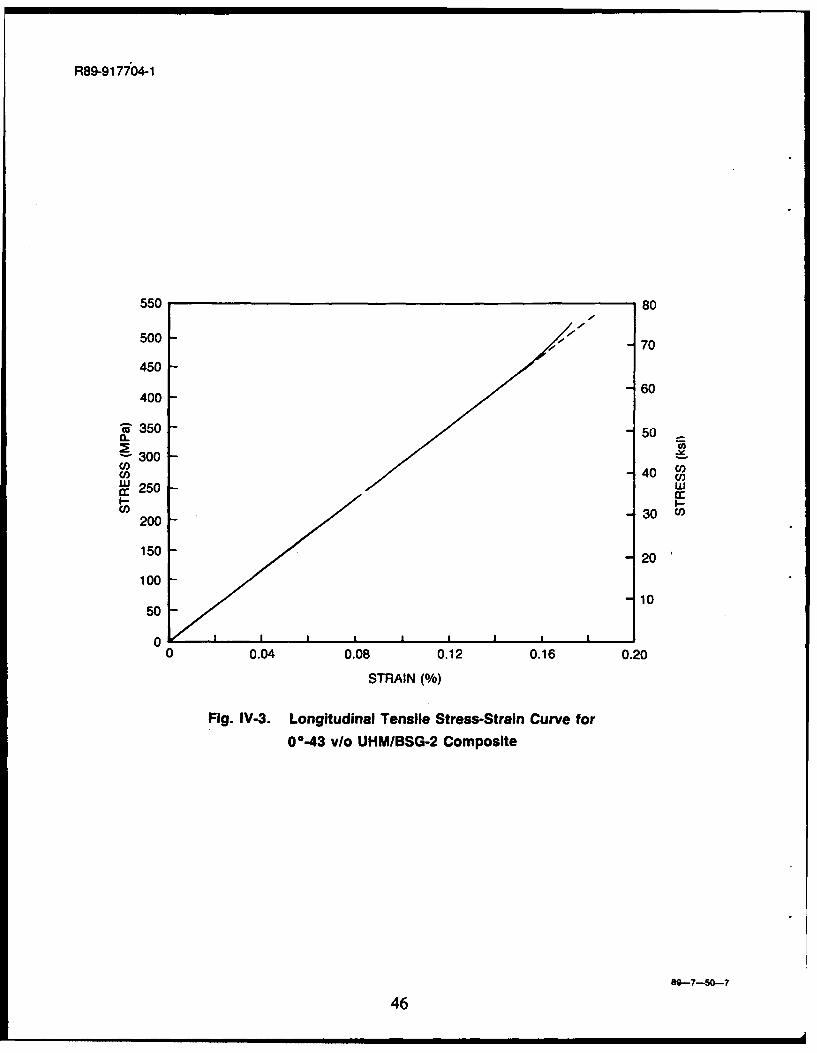
The stress-strain curve of the UHMIBSG-2 composite was somewhat unusual in that theelastic modulus of the composite increased after going through the PL, as shown in Figure IV-3. The elastic modulus of carbon fibers is known to increase with an increase in strain due to the
greater alignment of the graphite planes at higher strain levels [2]. However, the reason for theincrease in composite stiffness only in the UHM/BSG-2 system is not clear. This behavior isbelieved to be a true characteristic of this composite system since it has been repeated severaltimes among separate composites. Further investigation into this behavior is currently underway
at UTRC.
The fracture behavior of all the Pitch/BSG-2 composites was very similar to that of thePitch/BSG-1 composites described previously in Chapter III. As with the Pitch/BSG-1composites, pullout lengths in the Pitch/BSG-2 composites were considerably shorter than those
observed in the HMU/BSG-1 composite system. The similarity in fracture behavior correlateswell with the interlaminar shear strengths that were observed in the Pitch/BSG-2 composites,
38
R89-917704-1
which were all in the range of 50 MPa. These values are slightly higher than those observed inthe Pitch/BSG-1 system and imply that fiber-matrix interfacial shear strength may also besomewhat higher.
REFERENCES
1. P. W. McMillan, G, Academic Press, New York, 1979.
2. R. J. Diefendorf, RPI, 1988, personal communication.
3. V. C. Nardone and K. M. Prewo, J. Mater. Sci., 23 (1988) 168-180.
39
R89-917704-1
Table IV-I
Anisotropic Properties Displayed by Carbon Fibers
CTE (ppmioC)* Elastic Modulus (GPa)*Fibelr Asi Transverse A d Transverse,
HMU -0.7 13.1 380 10
P-100 -1.6 21.1 758 4
• Room temperature values
40
R89-9 17704-1
'U
06
0 I-
cc
020
00 0
mr) trn 00
02 cr-cc
cc
InE
41
R89-917704-1
-I4
0 0 r-
2Q6
6 05 8 o 6 6i
CI-
S 4D too C
r- C4 0- -
0 4 0% 00
rr tm~
enir enrn-
42
R89-9 17704-1
Table IV-4
Cyclic Tensile Properties for P-100/BSG-2 Composite
Initial ProportionalMaximum Elastic Limit Stress
-Cy l Sress Mfln Modusi(GEa) (M~a)
1 220 315 Linear to 220
2 367 315 Linear to 367
3 449 314 Linear to failureat 449
43
R89-91 7704-1
900 130
P-i O/BSG-21033 VOL% FIBER10
700 GPL w64ksi
90
w t6I-) II
/ P-1OOIBSG-1 50300 I 39 VOL% FIBER
/OPL 24 ksifPL-O.0 5 % 30
100 L1
STRAIN()0.10%
Fig. IV-1. Longitudinal Tensile Stress-Strain Behavior for 00 P-100/BSG-1 and0 P-100/BSG-2 Composites
89-7-50--5
44
R89-91 7704-1
48C 703RD CYCLE
420--6
2ND CYCLE
360--50
'~300-
40 ~
i) 240 -1ST CYCLE u
I~- 30n180-n
-20120-
60 -10
0 0
0.10%STRAIN (%)
Fig. IV-2. Cyclic Tensile Stress-Strain Behavior for00-36 v/o P-100/BSG-2 Composite
99-7-50-6
45
R89-91 7704-1
550 80
500 - 70
450
400 60
R' 350 -- 50
S300040
cU 250 -wco -30 WI200
150 -- 20
100 1510
50
0 0.04 0.08 0.12 0.16 0.20
STRAIN (%)
Fig. IV-3. Longitudinal Tensile Stress-Strain Curve for
00-43 via UHMIBSG-2 Composite
89--7-50-7
46
R89-917704-1
V. THERMAL EXPANSION BEHAVIOR OF PITCH FIBER REINFORCEDGLASS MATRIX COMPOSITES
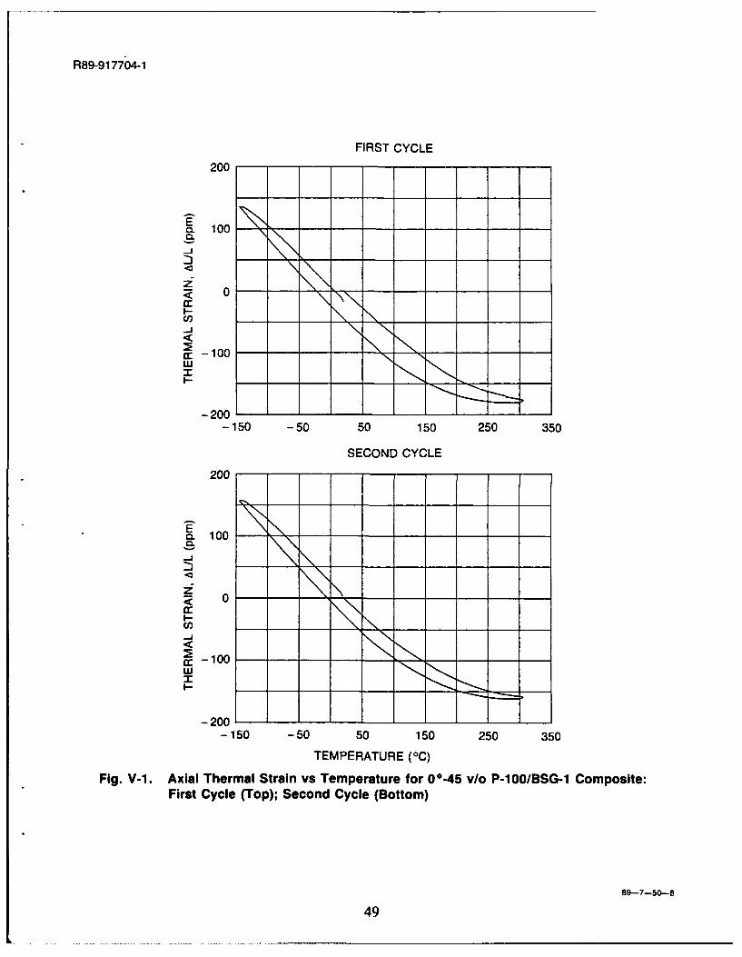
Axial coefficient of thermal expansion (CTE) behavior for the P-100/BSG-1, E-130/BSG-1, UHM/BSG-2, and E-130/BSG-2 composites was evaluated over the temperature range of- 1501C to +3000C. The thermal cycle was initiated at room temperature, followed by heating to300'C, cooling to -150uC, and re-heating back to room temperature. At least two thermal cycleswere always imposed. The CTE behavior of all the composite systems was found to be verysimilar. Typical thermal strain curves for the first and second cycles are shown in Figure V- 1,representing the P-100/BSG-1 composite system. For both cycles, the hysteresis was fairlylow, with values of -25 ppm or less over the entire second cycle. This represents the maximumdisplayed by all the Pitch/Glass composites. with other systems exhibiting less than 10 ppm overthe second thermal cycle. The initial cycle always exhibited a negative offset of 20-40 ppm at theend of the cycle; however, subsequent cycling was characterized by closed loop behavior. Theoffset is believed to be associated with matrix microcracking resulting from differential thermalexpansion between fiber and matrix and/or "settling" of the dilatometer during the first thermalcycle.
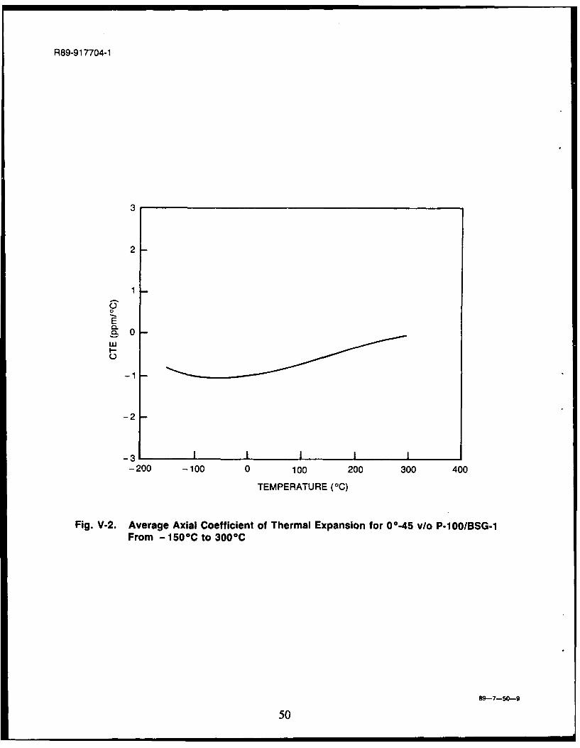
Composite CTE over the -150 0C to +300°C temperature range was derived from the thermalstrain curves by approximating the closed loop of the second thermal cycle with a 5th-orderpolynomial curve that was fit using least squares analytical techniques. The resulting CTE curvefor the P- 100/BSG- 1 composite is representative of all the compositcs and is presented in FigureV-2. From -150 0C to +100 0C, the CTE curve is relatively flat, varying from approiimately -0.75ppm/C to -1.0 ppm/°C. From 100C to 300C, the CTE increases linearly from -0.i5 ppm C tozero. The temperature range from -150 0C to +100 0C is probably of the most interest for space-based applications. The near linear CTE behavior and low hysteresis in this region isencouraging since it is believed that there are applications which can tolerate negative CTEbehavior as long as it is reproducible.
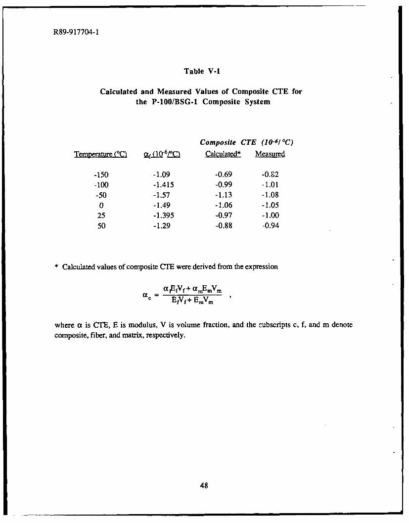
Table V-1 compares the measured values of composite CTE for the P-100/BSG-1composite with calculated values of CTE at several different temperatures. Calculated CTE'swere derived from the expression shown in the table. The temperature range extends only to500C since data on fiber CTE was not readily available for higher temperatures. The calculated
and measured values of ct are in close agreement over the temperature range shown in the table,suggesting that even though the matrix may experience some degree of microcracking duringthermal cycling, it maintains a large portion of its structural integrity and contributes stiffness tothe composite.
47
R89-917704-1
Table V-i
Calculated and Measured Values of Composite CTE forthe P-100/BSG-1 Composite System
Composite CTE (10-6/C)Temperture (°CI Qf ag-6LQ Calculated* Measured
-150 -1.09 -0.69 -0.,2-100 -1.415 -0.99 -1.01-50 -1.57 -1.13 -1.080 -1.49 -1.06 -1.05
25 -1.395 -0.97 -1.0050 -1.29 -0.88 -0.94
* Calculated values of composite CTE were derived from the expression
= afEfVf+ aEmVmEfVf+ EmVm
where a is CTE, E is modulus, V is volume fraction, and the -ubscripts c, f, and m denotecomposite, fiber, and matrix, respectively.
48
R89-917704-1
FIRST CYCLE
200
E0. 100
. 0
-Jn" - -0 \-
-
-200
-150 -50 50 150 250 350
SECOND CYCLE
200 0I
100
< 0
,M' -100-!-
w
-200-
-150 -50 50 150 250 350
TEMPERATURE (°C)
Fig. V-I. Axial Thermal Strain vs Temperature for 00-45 vlo P-100/BSG-1 Composite:First Cycle (Top); Second Cycle (Bottom)
89--7-50--8
49
R89-91 7704-1
3
2
1
0
-2
-200 -100 0 100 200 300 400
TEMPERATURE (00)
Fig. V-2. Average Axial Coefficient of Thermal Expansion for 00.45 vlo P-i OOIBSG-1From - 150 C to 300 C
89-7-50--9
50
R89-917704-1
VI. DEVELOPMENT OF HIGH TEMPERATURE MATRICES FOR CARBONFIBER REINFORCED GLASSES
High modulus composites utilizing pitch-based carbon fibers and borosilicate glassmatrices have been successfully developed with the hope that they will prove to be usefulmaterials for structural applications in space. However, in certain applications where thepotential exists for a large increase in temperature as the result of a thermal threat, borosilicateglass matrices may not provide suitable structural integrity, particularly once the temperatureexceeds 500-600'C. For this reason, the development of matrices capable of withstandingtemperatures of 800-1200'C was undertaken in order to improve the survivability of C/Glasscomposites being utilized in space-based systems. This chapter summarizes the initial workconducted in this development, including a description of the matrix materials used, roomtemperature tensile behavior, the relationship between fracture behavior arid compositemicrostructure, and high temperature flexural testing.
A. Matrix Compositions
Several matrix compositions were evaluated in this study and are listed in Table 11-1(located in the Experimental Procedure section). One composition, designated as BSG-3, was aglass containing a large fraction of Si0 2, which is the most refractory of the glass-formingoxides. This composition was chosen because it had demonstrated good high temperaturecapability in Nicalon®-reinforced composites [1]. The other two compositions, designated asLAS-I and BMAS, were glass-ceramics from the lithium aluminosilicate and barium magnesiumaluminosilicate systems, respectively. Glass-ceramics are materials that have the characteristicsof glasses at elevated temperatures (so that they can be easily deformed and fabricated) but can becrystallized through a suitable heat treatment to initiate nucleation and crystal growth (this heattreatment will be referred to hereafter as "ceraming"). By choosing the proper matrixcomposition, the crystalline phases that form during this ceraming treatment can be quiterefractory.
The primary crystalline phase that forms in the LAS-I composition when ceramed at
-900*C is P-quartz solid solution [2], which is comprised of [-eucryptite (LiAISiO 4 ) and [5-quartz (Si0 2). In the BMAS composition, the primary crystalline phase that precipitates whenceramed at -1 140'C is the totally-stuffed form of barium osumilite (BaMg 2Al6Si9O30 ). [5-quartzsolid solution and barium osumilite are both highly refractory crystalline phases, withtemperature capability above 1000"C. In both of these glass-ceramic compositions, the amountof amorphous material that converts to the crystalline phase is greater than 75%. It is desirable tohave as little amorphous material remaining after ceraming as possible, since the residual glass isthe temperature limiting phase in the glass-ceramic matrix. Large amounts of residual glass can
51
R89-917704-1
lead to a decrease in temperature capability through viscous relaxation mechanisms. (For a morecomplete discussion of glass-ceramics, Reference [3] is an excellent source of generalinformation.)
B. Composite Fabrication
Pitch fiber reinforced composites were fabricated using the BSG-3, LAS-I, and BMASmatrix compositions as detailed in Table VI-1. The ceraming cycle temperatures for the LAS-Icomposites were -780'C for nucleation followed by crystallization at -900'C, while thetemperatures used for the BMAS composites were -870°C for nucleation and-i 150'C for crystalgrowth. These ceraming temperatures were derived from differential thermal analysis traces ofthe starting glass powders. Ceraming was performed in a flowing argon atmosphere to minimizeoxidation of the carbon fibers. X-ray diffraction of the ceramed composites confirmed that theprimary crystalline phases were P-quartz solid solution in the LAS-I composites and barium
osumilite in the BMAS composites. Traces of mullite (3A120 3.2SIO 2) and hexacelsian(BaAl2 Si 2O8 ) were also identified.
C. Tensile Stress-Strain Behavior
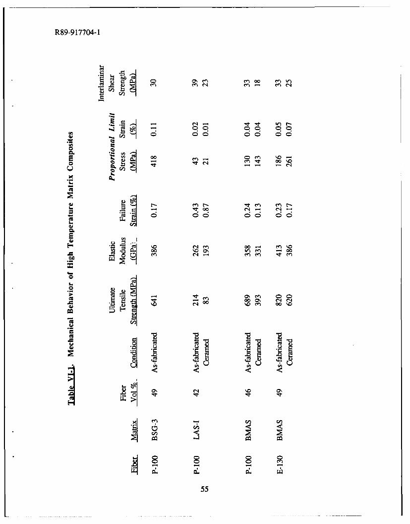
The tensile stress-strain behavior of the composites is summarized in Table VI-1. The P-100/BSG-3 composite demonstrated excellent strength and stiffness, with a high proportionallimit (PL) stress. These properties are comparable to those of the best Pitch/BSG-1 andPitch/BSG-2 composites (described previously in Chapters I and IV), with the added benefit ofincreased temperature capability (to be discussed in a subsequent section). The shape of thestress-strain curve for the P-100/BSG-3 composite is similar to that of the Pitch/BSG-2composite discussed earlier.
The stress-strain behavior of the composites containing glass-ceramic matrices variedgreatly between the LAS-I and BMAS systems and also within each system between the as-fabricated and ceramed conditions. The LAS-I composites exhibited much lower tensilestrengths and stiffnesses than the BMAS composites, with correspondingly low PL stress andstrain. The shape of the stress-strain curves was also quite unusual (Figure VI-1), with very flatregions of increasing strain at constant stress just prior to failure. These regions would seem tobe associated with a large amount of fiber slippage and pullout; however, the fracture surfacesdid not exhibit these characteristics, as shown in Figure VI-2. The ceramed sample possesses alarge degree of fiber pullout compared to P-100/BSG-1 composites (refer to Figure 111-7), butcertainly not to the extent suggested by the stress-strain curve. The fracture surface of the as-fabricated sample was very similar to that of P-100/BSG-1 composites, with very little fiberpullout. This lack of correlation between the stress-strain curves and the fracture surfaces hasnot yet been explained.
52
R89-917704-1
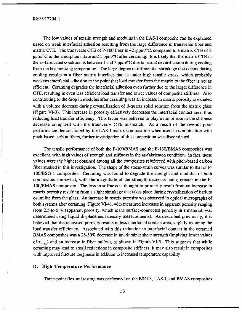
The low values of tensile strength and modulus in the LAS-I composite can be explainedbased on weak interfacial adhesion resulting from the large difference in transverse fiber andmatrix CTE. The transverse CTE of P-100 fiber is -21ppm/C, compared to a matrix CTE of 3ppm/C in the amorphous state and 1 ppm/*C after ceraming. It is likely that the matrix CTE inthe as-fabricated condition is between 1 and 3 ppm/0 C due to partial devitrification during coolingfrom the hot-pressing temperature. The large degree of differential shrinkage that occurs duringcooling results in a fiber-matrix interface that is under high tensile stress, which probablyweakens interfacial adhesion to the point that load transfer from the matrix to the fiber is not asefficient. Ceraming degrades the interfacial adhesion even further due to the larger difference inCTE, resulting in even less efficient load transfer and lower values of composite stiffness. Alsocontributing to the drop in modulus after ceraming was an increase in matrix porosity associatedwith a volume decrease during crystallization of P3-quartz solid solution from the matrix glass(Figure VI-3). This increase in porosity effectively decreases the interfacial contact area, thusreducing load transfer efficiency. This factor was believed to play a minor role in the stiffnessdecrease compared with the transverse CTE mismatch. As a result of the overall poorperformance demonstrated by the LAS-I matrix composition when used in combination withpitch-based carbon fibers, further investigation of this composition was discontinued.
The tensile performance of both the P-100/BMAS and the E-130/BMAS composites wasexcellent, with high values of strength and stiffness in the as-fabricated condition. In fact, thesevalues were the highest obtained among all the composites reinforced with pitch-based carbonfiber studied in this investigation. The shape of the stress-strain curves was similar to that of P-100/BSG-1 composites. Ceraming was found to degrade the strength and modulus of bothcomposites somewhat, with the magnitude of the strength decrease being greater in the P-100/BMAS composite. The loss in stiffness is thought to primarily result from an increase inmatrix porosity resulting from a slight shrinkage that takes place during crystallization of bariumosumilite from the glass. An increase in matrix porosity was observed in optical micrographs ofboth systems after ceraming (Figure VI-4), with measured increases in apparent porosity rangingfrom 2.5 to 5 % (apparent porosity, which is the surface-connected porosity in a material, wasdetermined using liquid displacement density measurements). As described previously, it isbelieved that the increased porosity results in less interfacial contact area, slightly reducing theload transfer efficiency. Associated with this reduction in interfacial contact in the ceramedBMAS composites was a 25-50% decrease in interlaminar shear strength (implying lower values
of tma) and an increase in fiber pullout, as shown in Figure VI-5. This suggests that whileceraming may lead to small reductions in composite stiffness, it may also result in compositeswith improved fracture toughness in addition to increased temperature capability
D. High Temperature Performance
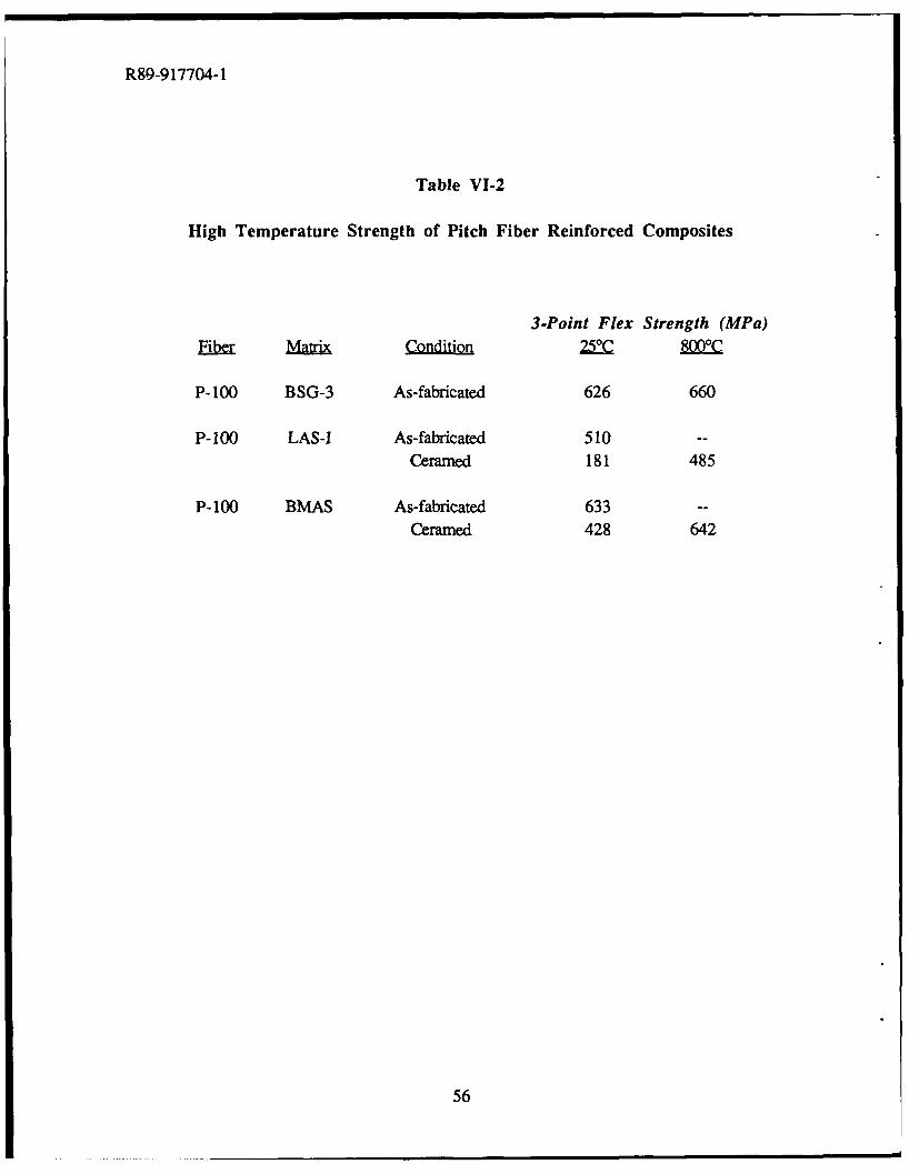
Three-point flexural testing was performed on the BSG-3, LAS-I, and BMAS composites
53

R89-917704-1
reinforced with P- 100 fiber at room temperature and at 800'C in an inert atmosphere. The resultsare presented in Table VI-2 and in Figure VI-6. It can be seen that all the compositesdemonstrated full retention of strength at the upper temperature of 800*C. It is expected that theLAS-I and BMAS composites should maintain structural integrity up to at least 1000C based onthe refractory nature of the matrix compositions. It is interesting to note that the flexural strengthin the LAS-I and BMAS ceramed composites exhibited a substantial increase in strength at 800'Ccompared to room temperature. This can be explained by again considering the difference intransverse CTE between fiber and matrix. As the composite is heated to 800*C, the differentialtransverse expansion results in greater fiber-matrix adhesion as the fiber expands more rapidlythan the matrix, thereby increasing load transfer efficiency.
REFERENCES
1. K. M. Prewo, "Silicon Carbide Yarn Reinforced Glass Matrix Composites," UTRC ReportR79-111330-6, UTRC Internal Report, October, 1979.
2. W. K. Tredway and K. M. Prewo, "Carbon Fiber Reinforced Glass Matrix Composites forSpace Based Applications," UTRC Report R87-917470-1, ONR Annual Report, August 30,1987.
3. P. W. McMillan, Glass-Ceramics, Academic Press, New York, 1979.
54
R89-9 17704-1
6 66 00 00 ioC
-I
0 I
it C1 0 0
14T00004- C14-
cq ~ ~ c en0004en
o0 'o0 )mU0
(00 00e 0 00\401
Cu14 oc 00 1
0 coa!55
R89-9 17704-1
Table VI-2
High Temperature Strength of Pitch Fiber Reinforced Composites
3-Point Flex Strength (MPa)
Elbar MariCndiio 22C B
P-100 BSG-3 As-fabricated 626 660
P-100 LAS-I As-fabricated 510 -
Ceramed 181 485
P-100 BMAS As-fabricated 633 -
Cerarned 428 642
56
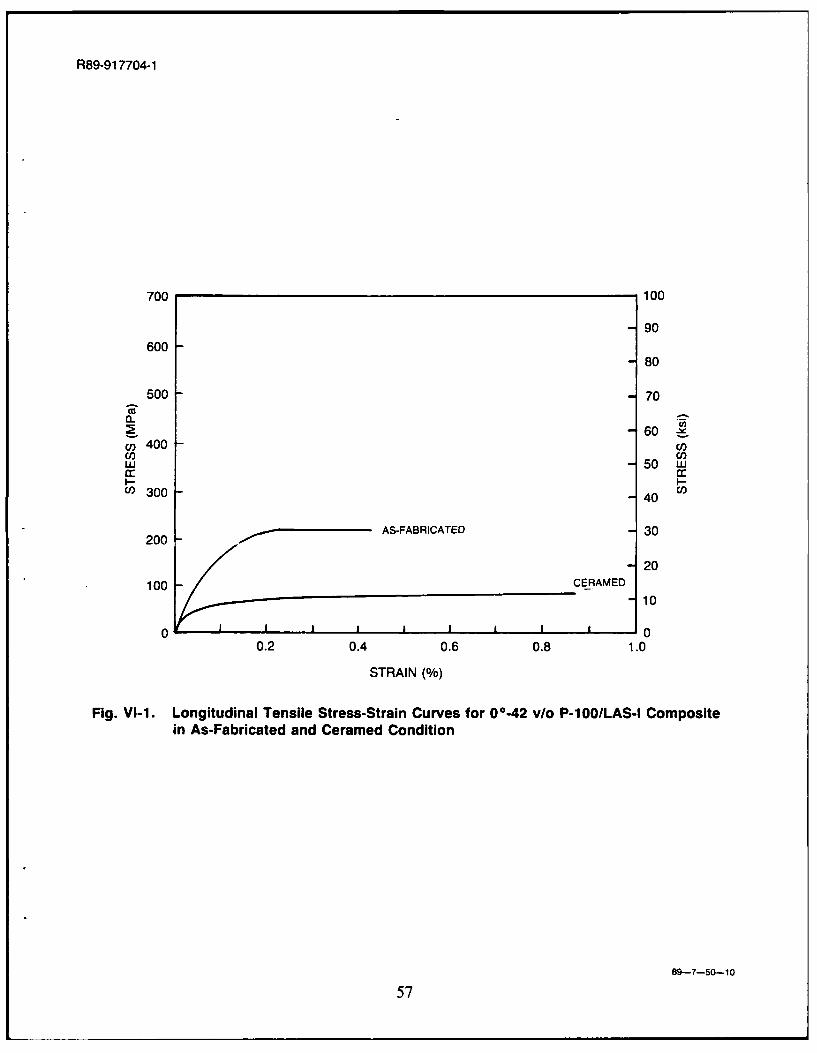
R89-91 7704-1
700 100
-90600 --
8
500 -- 70
2 -60 .cn 400 -(LU) 50 w.
C,) 300 -- 40
AS-FABRICATED -30200 __________
-20100 CERAMED
100 - -10
0 J 1 00.2 0.4 0.6 0.8 1.0
STRAIN ft)
Fig. VI-1. Longitudinal Tensile Stress-Strain Curves for OO*42 vlo P-100/LAS-l Compositein As-Fabricated and Ceramed Condition
89--7-50-10
57
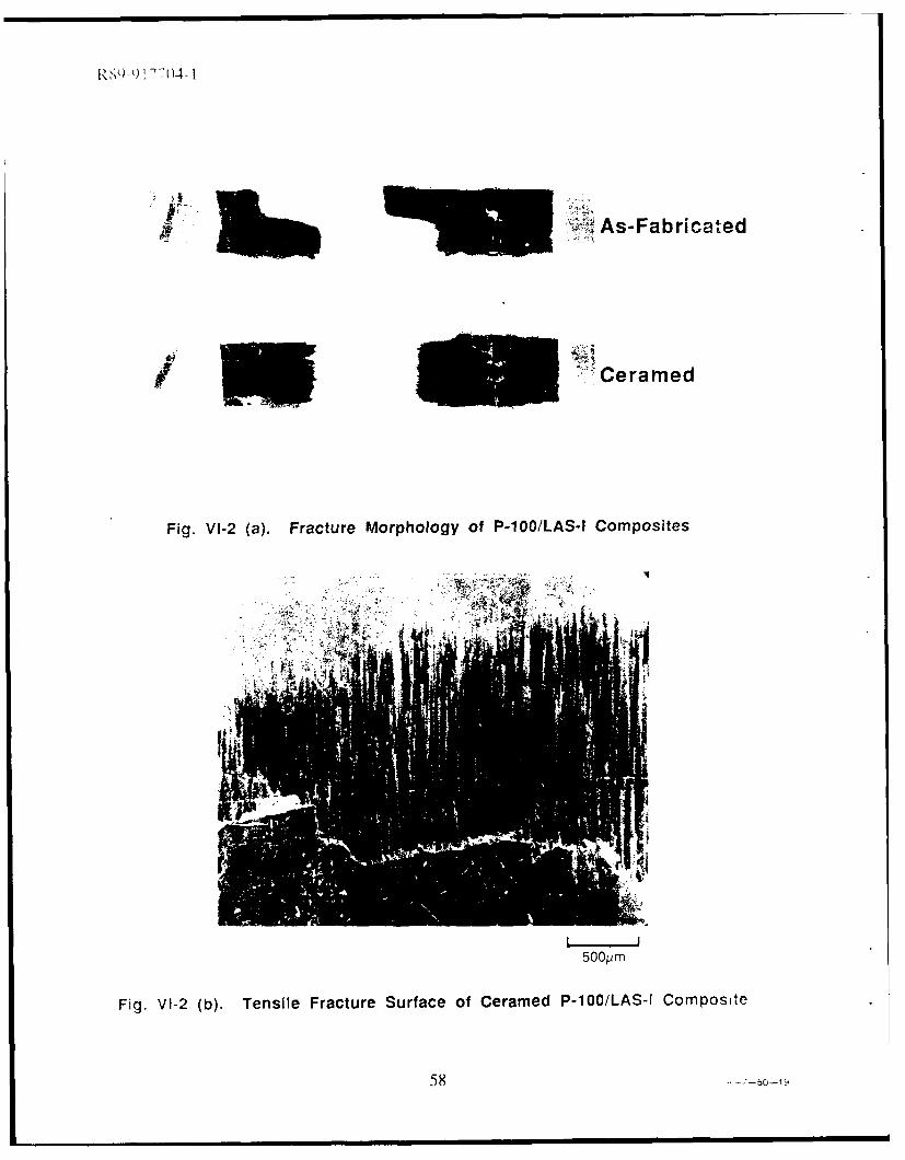
'S1) 04-1
- ~ As-Fabricat ed
I 5 jCeramed
Fig. VI-2 (a). Fracture Morphology of P-100/LAS-l Composites
500pm
Fig. VI-2 (b). Tensile Fracture Surface of Ceramed P-100/LAS-I Composite
58
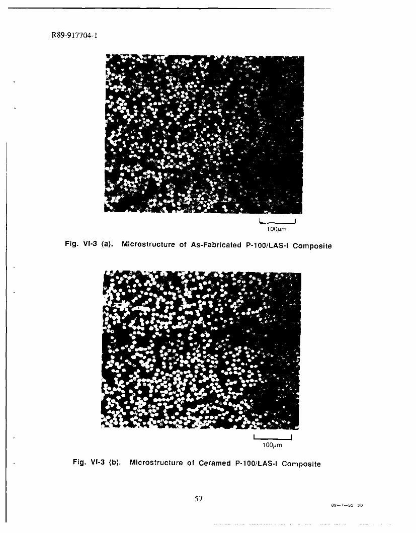
R89-9 17704-1
100/.4m
Fig. VI-3 (). Microstructure of AsFaraed P-la/LAS-I Composite
59)89- 7-50-20
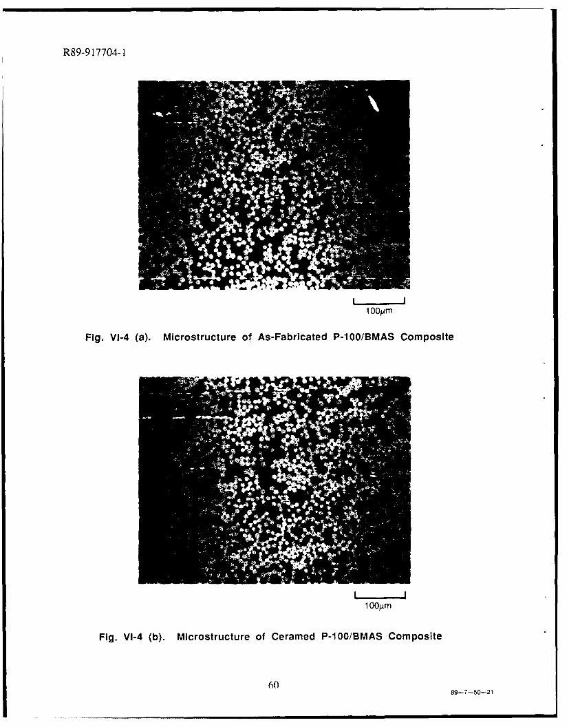
R89-917704-1
1OJm
Fig. VI-4 (a). Microstructure of As-Fabricated P-100/BM1VAS Composite
1 O0jAm
Fig. VI-4 (b). Microstructure of Ceramed P-100/B3MAS Composite
6089-7-50-21
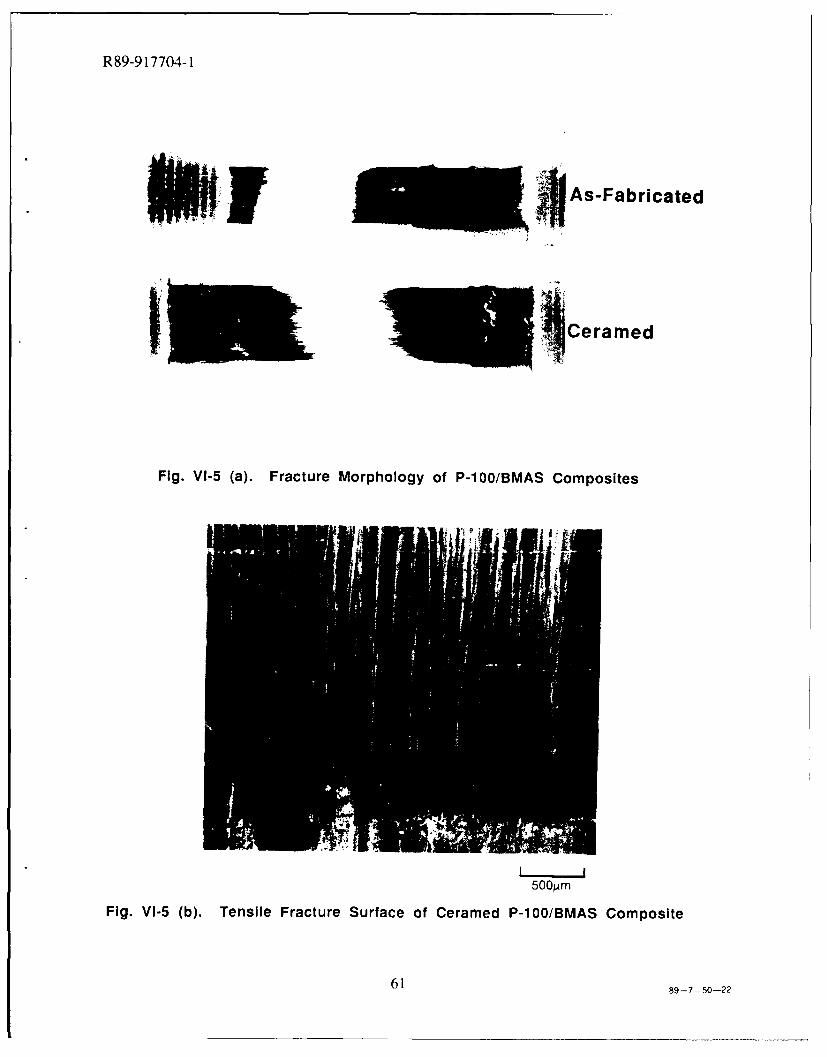
R89-917704-1
- As-Fabricated
Cerame d
Fig. Vt-5 (a). Fracture Morphology of P-100/B3MAS Composites
Fig. Vi-5 (b). Tensile Fracture Surface of Ceramed P-100/B3MAS Composite
61 89-7-50-22
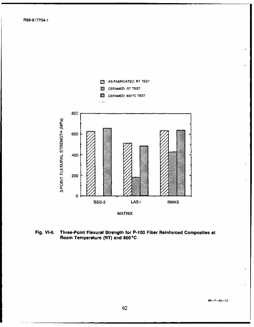
R89-91 7704-1
0 AS-FABRICATED; PT TEST
SCERAMED: RT TEST
0 CERAMED; 800-C TEST
BOO
~- 600
z
U)-j 400
200z
0BSG-3 LAS-I BMAS
MATRIX
Fig. VI-6. Three-Point Flexural Strength for P-100 Fiber Reinforced Composites atRoom Temperature (RT) and 8000C
89-7-50-12
62
R89-917704-1
VII. INTERFACE REACTIONS AND WETTING IN CARBON FIBERREINFORCED GLASS MATRIX COMPOSITES
C. G. Pantano, G. Chen and D. QiDepartment of Materials Science and Engineering
The Pennsylvania State UniversityUniversity Park, PA 16802
A. Introduction
The fiber/matrix interfaces in carbon-fiber reinforced glass matrix composites are createdduring their high temperature fabrication. Due to the very low surface energy of carbon (fibers),the molten glass is non-wetting. Thus, the pressure employed in hot-pressing the composite playsan important role not only in the composite densification, but also in the development of intimatesolid/liquid interfaces and in penetration ot the liquid into irregularities along the fiber surfaces. Ofcourse, the final characteristics and stability of this interface depends upon any chemical reactionswhich occur at elevated temperature, and further, upon the stresses which develop during cooling.Nevertheless, it seems likely that the intrinsic wetting and spreading of the glass matrix phase arefundamental to the overall interface evolution. To be sure, the absence of any significantadherence between the carbon fibers and glass matrix is responsible for the high-fracture toughtieqof these composites [1], and this is certainly related to the limited wettability in this system.
The primary objective of this study was to evaluate effects of the glass matrix compositionupon wetting and spreading of the glass on Pitch- and PAN-based carbon fibers. A secondaryobjective was to observe the relationship between wetting and any associated degradation of thecarbon fibers. Two different methods were developed to study these interactions. In one case,hot-pressed composites were heated in an inert atmosphere at temperatures in excess of thesoftening point. This caused the glass matrix phase to de-wet the fibers, and thereby, to exposethe fiber surfaces and to form micro-sessile drops on the fiber surfaces. In the other method, thinglass coatings were deposited on single filaments and on fiber tows using a sol/gel technique.These model fiber/glass interfaces have been used to study the interface reactions and wettingdirectly. The advantages of this method are that the glass composition can be easily varied usingso!/gel synthesis, and that the carbon fiber surfaces - with a thin coating of the matrix glass - can bereadily observed and characterized.
The effects of B20 3, Na20 and variable valence transition metal oxides (Nb2O5 and MO03)in the glass matrix composition were of primary interest. The oxidation of carbon fibers isinhibited in the presence of B20 3 [2-4], and it is catalyzed in the presence of Na20 and many other
63
R89-917704-1
metal oxides [5-9]. MoO3 is also an exceptional oxidation catalyst for carbon, whereas no catalyticeffect of Nb2O5 has been reported [6]. In addition, the variable valence transition metal oxidesinfluence the local redox equilibria at the fiber matrix interface, and thereby, can lead to gaseous
and solid phase interphase reaction products. Here, Nb20 5 and MoO3 were chosen for studybecause their effect upon the interface thermochemistry and composite properties have already beenreported [10, 11]. The experiments were carried-out on both Pitch and PAN based fibers to
evaluate any differences in their surface chemical and structural characteristics. Here, too, it hasalready been reported [12] that the mechanical performance of Pitch- and PAN-based fibercomposites are different, and in some cases, this could be attributed to interface effects. Finally,the effects of inert versus reducing atmospheres upon the interface reactions were examined.
B. Experimental Procedure
The primary variables in this study were the glass matrix composition and the type of
carbon fiber. Table I presents the various glass compositions, and the type of specimen in whichthey were evaluated. The carbon fibers were either PAN-based HMUa, or Pitch-based p- 100 b.
The hot-pressed composites were supplied by United Technologies Research Center
(UTRC). Uniaxial, continuous fiber composites were fabricated by hot-pressing pre-preggedtapes which were made by using the glass frit slurry infiltration technique [1]. The glasscompositions used in these hot-pressed composites were CGW 7740 (81SiO 2, 13B 20 3, 4Na2Oand 2A1203) and some special sodium borosilicate (NBS) melts where the A120 3 was eliminated orwhere 1% Nb2 0 5 or 1% MoO3 was added. In the case of these hot-pressed composites, fracture
surfaces were examined after a heat-treatment in high-purity argon at 1200°C and 1300'C. Thisheat treatment caused de-wetting of the glass matrix, and thereby, sessile drops were created andthe carbon fiber surfaces were exposed.
The glass thin film coatings were prepared using a sol/gel method. Most of the rawmaterials were organometallic compounds: tetraethoxysilane (TEOS), trimethyl borate, aluminum
sec-butoxide, sodium acetate, niobium ethoxide and molybdenum dichloride dioxide. Thesecompounds were mixed and hydrolyzed stepwise in an ethanol solution. In all cases, a transparentsolution could be obtained. The use of these solutions to fabricate glass matrix composites hasalready been reported [13]. Here, the solutions were used to dip-coat 10 cm long carbon-fiberfilaments or yarns. These carbon fibers were obtained directly from the manufacturers without anysizing applied. The fibers were held in the solution for 10 seconds, slowly withdrawn, and thendried in air at room temperature. The coated fibers were heated in air at 400'C for 30 minutes to
remove residual organics and water. Finally, the fibers were heated at 1200'C or 1300'C in argon
a Hercules, Magna, UT 84044
b Amoco Performance Products, Inc., Ridgefield, Cr 06877
64
R89-917704-1
(->ppm 02) or in carbon monoxide for 30 to 45 minutes. The fibers were then examined in the
scanning electron microscope (SEM).
C. RESULTS
C. 1. Transition-Metal Oxide Effects
The SEM micrographs in Figure 1, show the effects of MoO3 and Nb2 0 5 upon thefiber/matrix interaction in HMUf7740 composites. The composites were fractured along the fiberdirection, and then were heated in argon for two hours at 1300'C to cause the glass matrix phase tode-wet the fiber surfaces. The micrograph in Figure I a shows that little or no degradation of thefibers is apparent, whereas in Figures lb and Ic, the influence of MoO 3 and Nb20 5 - even at the1% level - is evident. The reactions that caused most of this degradation probably occurred duringboth the initial hot-pressing of these composites, although some additional reaction is likely duringthe de-wetting. (The de-wetting was carried out at 1200'C also, and the extent of degradation wascomparable.) It seems certain that the fiber degradation is responsible for the poor mechanicalperformance reported in these transition-metal doped systems [ 11].
Figures 2, 3 and 4 show a similar set of micrographs, except in these cases, the interactionoccurred between thin sol/gel glass coatings and the fiber surfaces. In general, the extent ofdegradation is less than in the case of the hot-pressed composites. This is due to differences inthermal history of the two specimens. The coated fibers (in Figures 2, 3 and 4) were held in argonat 1000-1200°C for only 45 min, whereas the composites (in Figure 1) were hot-pressed at 1200-1300'C, and then later, heated further at 12000C or 1300°C to de-wet the fibers. Nevertheless, theeffects of the matrix compositions are consistent. Namely, Lne fibers which were coated withglasses containing Nb20 5 or MoO3 show definite pitting and attack of the surface, whereas theundoped borosilicate composition shows no obvious attack of the fibers. The micrographs inFigures 2, 3 and 4 also show the difference between HMU versus P-100 carbon fibers. It isevident that the type of fiber influences the morphology of the attack. The P- 100 fibers are pittedpreferentially along the grooves in the corrugated surface structure, and moreover, the grooves areelongated. In contrast, the HMU fibers show rounded pits which are more randomly distributedover the fiber surfaces.
The micrographs in Figure 2 show that the contact angle between the oxide glass andcarbon fiber is different for P-100 (Pitch) versus HMU (PAN) carbon fiber. This effect of thecarbon fiber type upon the contact angle was also observed in the hot-pressed composites Thecontact angle is usually greater than 900 on the HMU fibers, and less than 900 on the P-100 fibers.In most cases, the sessile drops were smaller and more numerous on the P-100 fibers. Thepresence of Nb 20 5 01 MoO 3 did not significantly influence the observed contact angle, but it isshown below that the B20 3/Na2O concentration ratio exhibits a big effect upon the wetting.
65
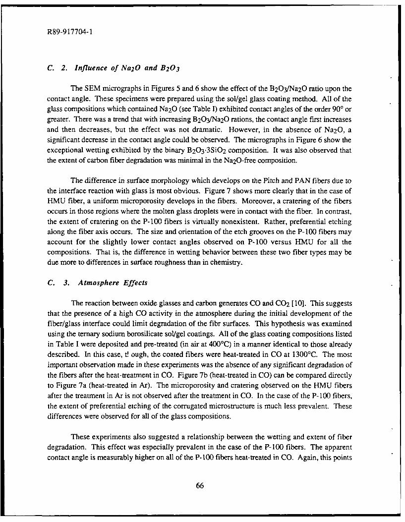
R89-917704-1
C. 2. Influence of Na2O and B2 0 3
The SEM micrographs in Figures 5 and 6 show the effect of the B203/Na2O ratio upon thecontact angle. These specimens were prepared using the sol/gel glass coating method. All of theglass compositions which contained Na20 (see Table I) exhibited contact angles of the order 900 orgreater. There was a trend that with increasing B203/Na2O rations, the contact angle first increasesand then decreases, but the effect was not dramatic. However, in the absence of Na20, asignificant decrease in the contact angle could be observed. The micrographs in Figure 6 show theexceptional wetting exhibited by the binary B20 3.3SiO2 composition. It was also observed thatthe extent of carbon fiber degradation was minimal in the Na20-free composition.
The difference in surface morphology which develops on the Pitch and PAN fibers due tothe interface reaction with glass is most obvious. Figure 7 shows more clearly that in the case ofHMU fiber, a uniform microporosity develops in the fibers. Moreover, a cratering of the fibersoccurs in those regions where the molten glass droplets were in contact with the fiber. In contrast,the extent of cratering on the P-100 fibers is virtually nonexistent. Rather, preferential etchingalong the fiber axis occurs. The size and orientation of the etch grooves on the P-100 fibers mayaccount for the slightly lower contact angles observed on P-100 versus HMU for all thecompositions. That is, the difference in wetting behavior between these two fiber types may bedue more to differences in surface roughness than in chemistry.
C. 3. Atmosphere Effects
The reaction between oxide glasses and carbon generates CO and CO2 [10]. This suggeststhat the presence of a high CO activity in the atmosphere during the initial development of thefiber/glass interface could limit degradation of the fibr surfaces. This hypothesis was examinedusing the ternary sodium borosilicate sol/gel coatings. All of the glass coating compositions listedin Table I were deposited and pre-treated (in air at 400'C) in a manner identical to those alreadydescribed. In this case, t! ough, the coated fibers were heat-treated in CO at 1300'C. The mostimportant observation made in these experiments was the absence of any significant degradation ofthe fibers after the heat-treatment in CO. Figure 7b (heat-treated in CO) can be compared directlyto Figure 7a (heat-treated in Ar). The microporosity and cratering observed on the HMU fibersafter the treatment in Ar is not observed after the treatment in CO. In the case of the P- 100 fibers,the extent of preferential etching of the corrugated microstructure is much less prevalent. Thesedifferences were observed for all of the glass compositions.
These experiments also suggested a relationship between the wetting and extent of fiberdegradation. This effect was especially prevalent in the case of the P-100 fibers. The apparentcontact angle is measurably higher on all of the P-100 fibers heat-treated in CO. Again, this points
66
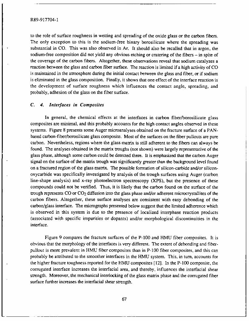
R89-917704-1
to the role of surface roughness in wetting and spreading of the oxide glass or the carbon fibers.The only exception to this is the sodium-free binary borosilicate where the spreading was
substantial in CO. This was also observed in Ar. It should also be recalled that in argon, thesodium-free composition did not yield any obvious etching or cratering of the fibers - in spite ofthe coverage of the carbon fibers. Altogether, these observations reveal that sodium catalyzes areaction between the glass and carbon fiber surface. The reaction is limited if a high activity of COis maintained in the atmosphere during the initial contact between the glass and fiber, or if sodiumis eliminated in the glass composition. Finally, it shows that one effect of the interface reaction isthe development of surface roughness which influences the contact angle, spreading, andprobably, adhesion of the glass on the fiber surface.
C. 4. Interfaces in Composites
In general, the chemical effects at the interfaces in carbon fiber/borosilicate glasscomposites are minimal, and this probably accounts for the high contact angles observed in these
systems. Figure 8 presents some Auger microanalyses obtained on the fracture surface of a PAN-based carbon-fiber/borosilicate glass composite. Most of the surfaces on the fiber pullouts are purecarbon. Nevertheless, regions where the glass matrix is still adherent to the fibers can always befound. The analyses obtained in the matrix troughs (not shown) were largely representative of theglass phase, although some carbon could be detected there. It is emphasized that the carbon Augersignal on the surface of the matrix trough was significantly greater than the background level found
on a fractured region of the glass matrix. The possible formation of silicon-carbide and/or silicon-oxycarbide was specifically investigated by analysis of the trough surfaces using Auger (carbonline-shape analysis) and x-ray photoelectron spectroscopy (XPS), but the presence of thesecompounds could not be verified. Thus, it is likely that the carbon found on the surface of the
trough represents CO or C02 diffusion into the glass phase and/or adherent microcrystallites of thecarbon fibers. Altogether, these surface analyses are consistent with easy debonding of thecarbon/glass interface. The micrographs presented below suggest that the limited adherence whichis observed in this system is due to the presence of localized interphase reaction products(associated with specific impurities or dopants) and/or morphological discontinuities in the
interface.
Figure 9 compares the fracture surfaces of the P-100 and HMU fiber composites. It is
obvious that the morphology of the interfaces is very different. The extent of debonding and fiber-pullout is more prevalent in HMU fiber composites than in P-100 fiber composites, and this canprobably be attributed to the smoother interfaces in the HMU system. This, in turn, accounts forthe higher fracture toughness reported for the HMU composites [12]. In the P-100 composite, the
corrugated interface increases the interfacial area, and thereby, influences the interfacial shearstrength. Moreover, the mechanical interlocking of the glass matrix phase and the corrugated fiber
surface further increases the interfacial shear strength.
67
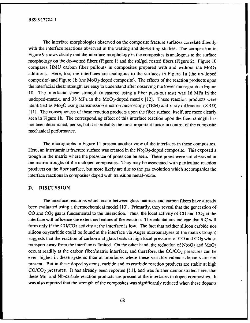
R89-917704-1
The interface morphologies observed on the composite fracture surfaces correlate directlywith the interface reactions observed in the wetting and de-wetting studies. The comparison inFigure 9 shows clearly that the interface morphology in the composites is analogous to the surfacemorphology on the de-wetted fibers (Figure 1) and the sol/gel coated fibers (Figure 2). Figure 10compares HMU carbon fiber pullouts in composites prepared with and without the MoO 3
additions. Here, too, the interfaces are analogous to the surfaces in Figure la (the un-dopedcomposite) and Figure lb (the MoO 3-doped composite). The effects of the reaction products uponthe interfacial shear strength are easy to understand after observing the lower micrograph in Figure10. The interfacial shear strength (measured using a fiber push-out test) was 16 MPa in theundoped-matrix, and 38 MPa in the MoO3-doped matrix [12]. These reaction products wereidentified as Mo 2C using transmission electron microscopy (TEM) and x-ray diffraction (XRD)[ 11]. The consequences of these reaction products upon the fiber surface, itself, are more clearlyseen in Figure l b. The corresponding effect of this interface reaction upon the fiber strength hasnot been determined, per se, but it is probably the most important factor in control of the compositemechanical performance.
The micrographs in Figure 11 present another view of the interfaces in these composites.Here, an interlaminar fracture surface was created in the Nb205-doped composite. This exposed atrough in the matrix where the presence of pores can be seen. These pores were not observed inthe matrix troughs of the undoped composites. They may be associated with particulate reactionproducts on the fiber surface, but more likely are due to the gas evolution which accompanies theinterface reactions in composites doped with transition metal-oxide.
D. DISCUSSION
The interface reactions which occur between glass matrices and carbon fibers have alreadybeen evaluated using a thermochemical model [10]. Primarily, they reveal that the generation ofCO and C02 gas is fundamental to the interaction. Thus, the local activity of CO and C02 at theinterface will influence the extent and nature of the reaction. The calculations indicate that SiC willform only if the CO/CO2 activity at the interface is low. The fact that neither silicon carbide norsilicon oxycarbide could be found at the interface via Auger microanalyses of the matrix trough)suggests that the reaction of carbon and glass leads to high local pressures of CO and CO2 whosetransport away from the interface is limited. On the other hand, the reduction of Nb2O5 and MoO 3
occurs readily at the carbon fiber/matrix interface, and therefore, the CO/CO2 pressures can beeven higher in these systems than at interfaces where these variable valence dopants are notpresent. But in these doped systems, carbide and oxycarbide reaction products are stable at highCO/CO 2 pressures. It has already been reported [11], and was further demonstrated here, thatthese Mo- and Nb-carbide reaction products are present at the interfaces in doped composites. Itwas also reported that the strength of the composites was significantly reduced when these dopants
68
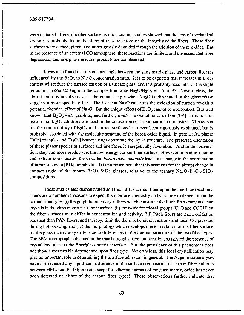
R89-917704-1
were included. Here, the fiber surface reaction coating studies showed that the loss of mechanicalstrength is probably due to the effect of these reactions on the integrity of the fibers. These fibersurfaces were etched, pitted, and rather grossly degraded through the addition of these oxides. Butin the presence of an external CO atmosphere, these reactions are limited, and the associated fiberdegradation and interphase reaction products are not observed.
It was also found that the contact angle between the glass matrix phase and carbon fibers isinfluenced by the B20 3 to Nq2 C coa,,.cntrati,- :atlo. I is to be expectd that increases in B2 0 3
content will reduce the surface tension of a silicate glass, and this probably accounts for the slightreduction in contact angle in the composition rante Na20/B203 = 1.5 to .33. Nevertheless, theabrupt and obvious decrease in the contact angle when Na20 is eliminated in the glass phasesuggests a more specific effect. The fact that Na20 catalyzes the oxidation of carbon reveals apotential chemical effect of Na20. But the unique effects of B2 0 3 cannot be overlooked. It is wellknown that B20 3 wets graphite, and further, limits the oxidation of carbon [2-41. It is for thisreason that B2 0 3 additions are used in the fabrication of carbon-carbon composites. The reasonfor the compatibility of B20 3 and carbon surfaces has never been rigorously explained, but isprobably associated with the molecular structure of the boron oxide liquid. In pure B203, planar[B0 3] triangles and I]B30 6] boroxyl rings constitute the liquid structure. The preferred orientationof these planar species at surfaces and interfaces is energetically favorable. And in this orienta-tion, they can more readily wet the low energy carbon fiber surface. However, in sodium-borateand sodium-borosilicates, the so-called boron-oxide anomaly leads to a change in the coordinationof boron to create [BO 4] tetrahedra. It is proposed here that this accounts for the abrupt change incontact angle of the binary B2 0 3 -SiO 2 glasses, relative to the ternary Na20-B 2 03-SiO2
compositions.
These studies also demonstrated an effect of the carbon fiber upon the interface reactions.There are a number of reasons to expect the interface chemistry and structure to depend upon thecarbon fiber type; (i) the graphitic microcrystallites which constitute the Pitch fibers may nucleatecrystals in the glass matrix near the interface, (ii) the oxide functional groups (C=O and COOH) onthe fiber surfaces may differ in concentration and activity, (iii) Pitch fibers are more oxidationresistant than PAN fibers, and thereby, limit the thermochemical reactions and local CO pressureduring hot pressing, and (iv) the morphology which develops due to oxidation of the fiber surfaceby the glass matrix may differ due to differences in the internal structure of the two fiber types.The SEM micrographs obtained in the matrix troughs have, on occasion, suggested the presence ofcrystallized glass at the fiber/glass matrix interface. But, the prevalence of this phenomena doesnot show a measurable dependence upon fiber type. Nevertheless, this local crystallization mayplay an important role in determining the interface adhesion, in general. The Auger microanalyseshave not revealed any significant difference in the surface composition of carbon fiber pulloutsbetween HMU and P- 100; in fact, except for adherent extracts of the glass matrix, oxide has neverbeen detected on either of the carbon fiber types! These observations further indicate that
69
R89-917704-1
differences in the interfacial shear strength between Pitch- and PAN-based carbon fiber compositesare associated with the morphology differences shown in Figure 9. Since both fiber types areoxidized to a certain extent by the glass matrix during processing, the difference in interfacemorphology is probably related to the internal microstructure of the fiber. This creates a uniquesurface structure during oxidative etching of the fibers by the molten matrix phase. This effect isevident at the interfaces in the composites (Figure 9), as well as on the surface of the de-wetted andglass coated fibers (Figures 2-7). The enhanced wetting of the P- 100 fibers by the glass matrixoccurs due to roughness effects, and not necessarily to chemical differences at the interface.
E. SUMMARY
The contact angle of the borosilicate glass matrix phase on the carbon fibers is of the order90-150'. The primary reaction creates gaseous reaction products whose high local activity andlimited diffiusivity eliminates the possible formation of solid interphase reaction products. Thegaseous reaction products probably contribute toward the creation of a weak bonding layer in thefinal composite, although localized etching and/or reactions with impurities may cause someadherence. This is consistent with the rather clean interfacial debonding observed in this system.
The interface reactions were significantly enhanced when the matrix phase was doped withsmall concentrations of reducable transition metal oxides. In this case, degradation of the fiberswas most apparent, but in addition, the formation of interphase reaction products could be clearlyobserved. These effects led to a significant reduction in the mechanical properties of thecomposites. The observed influence of these dopants provides insight to the interface reactions,but perhaps of more significance, they suggest that impurities in the matrix and/or fibers can lead tolocalized reactions at the interface.
Finally, some of the effects of glass matrix composition and carbon fiber type weredemonstrated. The wetting was greatly enhanced in the case of binary borosilicate compositions,but it remains to be determined whether enhanced wetting influences the final properties of thecomposite. The creation of distinct interface morphology and rugosity was most prevalent in thePitch-based fibers. The rough, corrugated surface on the P-100 fibers is intrinsic to their internalstructure which is exposed during oxidation by the matrix. The enhanced wetting or adhesion dueto roughness is consistent with the high interfacial shear strength, as well as the limited debondingand fiber pull-out, exhibited by the P-100 composites.
ACKNOWLEDGEMENT
The authors gratefully acknowledge the Office of Naval Research (ONR N00014-55-C-0332 and N00014-87-K-0247) for their support of this research.
70
R89-917704-1
REFERENCES
1. K. M. Prewo, J. J. Brennan and G. K. Layden, "Fiber Reinforced Glass and Glass-
Ceramics for High Performance Applications," Am. Cer. Soc. Bull., 65 (2), 305-313,322 (1986).
2. D. W. McKee, C. L. Spiro and E. J. Lamby, "The Effect of Boron Additives on the
Ocidation Behavior of Carbons," Carbon, 22 (6), 507-511 (1984).
3. P. Ehrburger, P. Baranne and J. Lahaye, "Inhibition of the Oxidation of Carbon-Carbon
Composite by Boron Oxide," Carbon, 24 (4), 495-499 (1986).
4. D. W. McKee, "Borate Treatment of Carbon Fibers and Carbon/Carbon Composites for
Improved Oxidation Resistance," Carbon, 24 (6), 737-741 (1986).
5. P. L. Walker, Jr., M. Shelef and R. A. Anderson, "Catalysis of Carbon Gasification," in
Chemistry and Physics of Carbon, P. L. Walker, Ed., Vol. 4, 287-383 (1968).
6. D. W. McKee, "Metal Oxides as Catalysts for the Oxidation of Graphite," Carbon, 8, 623-
635 (1970).
7. D. W. McKee and D. Chaterji, "The Catalytic Behavior of Alkali Metal Carbonates and
Oxides in Graphite Oxidation Reactions," Carbon, 13, 381-390 (1975).
8. B. P. Jalan and Y. K. Rao, "A Study of the Rates of Catalyzed Boudouard Reactions,"
Carbon, 16, 175-184 (1978).
9. Y. K. Rao and A. A. Adjonolo, "Catalysis of the Boudouard Reactions," High
Temperature Science, 19, 51-77 (1985).
10. P. M. Benson, K. E. Spear and C. G. Pantano, "Thermochemical Analyses of Interface
Reactions in Carbon-Fiber Reinfored Glass Matrix Composites," in Ceramic
Microstructures '86, J. A. Pask and A. G. Evans, Ed., Plenum Press, New York, 415-
425 (1987).
11. K. M. Prewo, W. Tredway and C. G. Pantano, "Carbon Fiber Reinforced Glass Matrix
Composites for Space Based Applications, UTRC Report R87-917470-1, ONR Annual
Report, August 30, 1987.
12. W. Tredway, K. M. Prewo and C. G. Pantano, to appear in Carbon, 1989.
71
R89-917704-1
13. D. Qi and C. G. Pantano, "Sol/Gel Processing of Carbon-Fiber Reinforced Glass MatrixComposites," in Ultrastructure Processing of Advanced Ceramics, J. D. Mackenzie and D.R. Ulrich, Ed., John Wiley and Sons, Inc., 635-649 (1988).
72
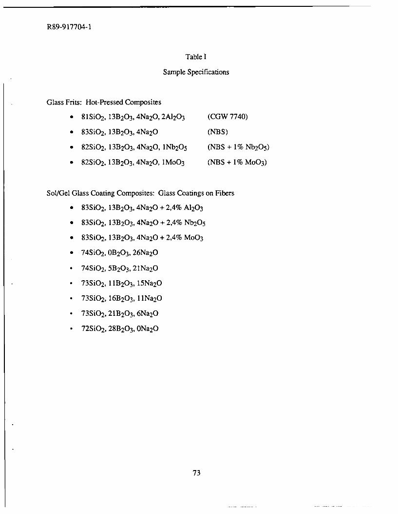
R89-9 17704-1
Table I
Sample Specifications
Glass Frits: Hot-Pressed Composites
* 81SiO2 , 13B 203 , 4Na2O, 2A1203 (CGW 7740)
" 83SiO2 , 13B 203 , 4Na2O (NBS)
* 82SiO2 , 13B2 03, 4Na2O, lNb2O5 (NBS + 1% Nb2O 5)
" 82SiO2, 13B 203, 4Na2O, 1MoO3 (NBS + 1% M003)
Sol/Gel Glass Coating Composites: Glass Coatings on Fibers
* 83Si0 2 , 13B 203 , 4Na2O +2,4% A1203
* 83Si0 2 , 13B2 03, 4Na2O + 2,4% Nb2O5
" 83Si0 2 , 13B20 3, 4Na2O + 2,4% MoO3
" 74S i0 2 , 0B203 , 26Na2O
0 74Si0 2 , 5B20 3, 21Na2 O
* 73Si0 2 , 11B2 03, 15Na2 O
* 73Si0 2 , 16B2 03, llNa2O
* 73Si0 2 , 21B20 3, 6Na2 O
* 72SiO 2, 28B20 3, ONa2O
73
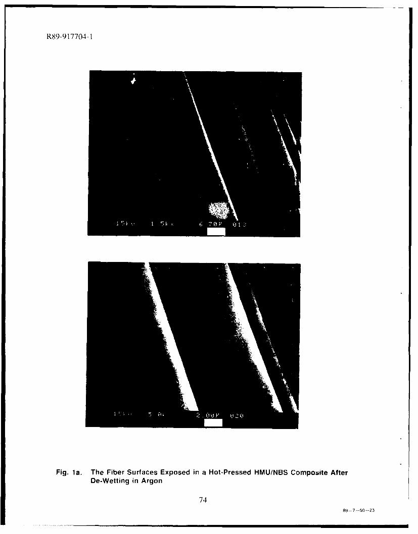
R89-917704-1
Fig. la. The Fiber Surfaces Exposed in a Hot-Pressed HMUINBS Composite AfterDe-Wetting in Argon
7489- 7-SO0-23
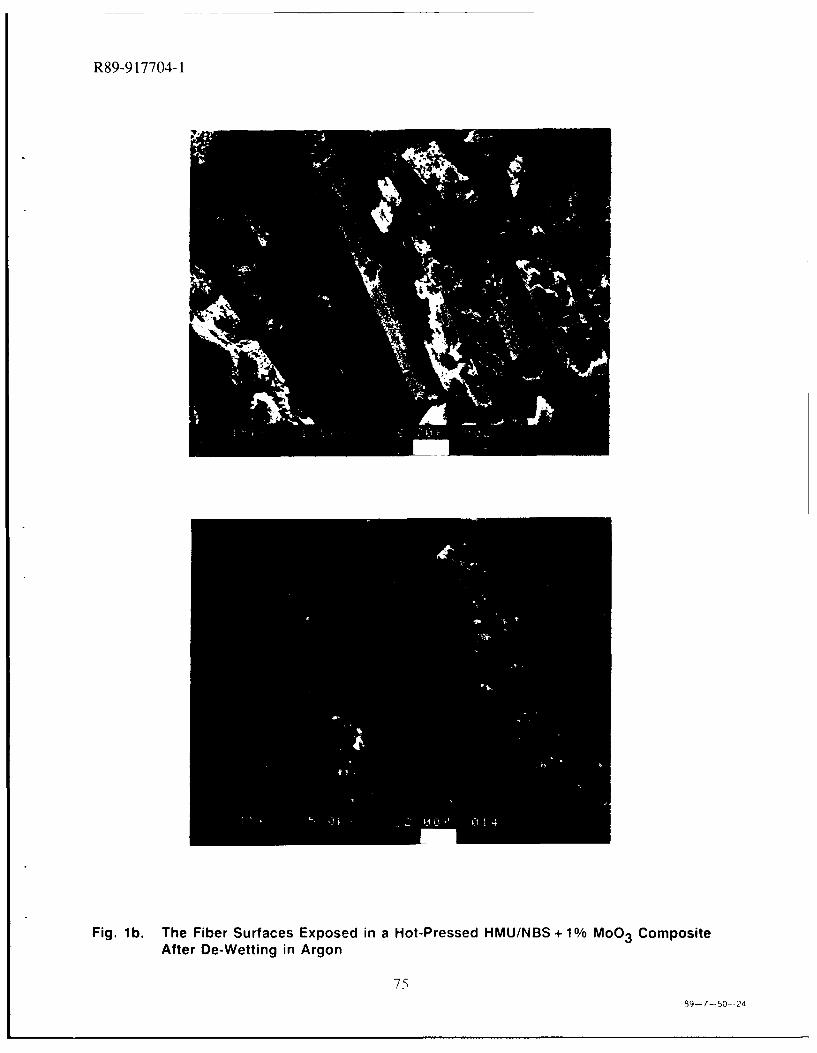
R89-9 17704-1
Fig. l b. The Fiber Surfaces Exposed in a Hot-Pressed HMU/NBS + 1 % MoO3 CompositeAfter De-Wetting in Argon
7589- 7-50- -24
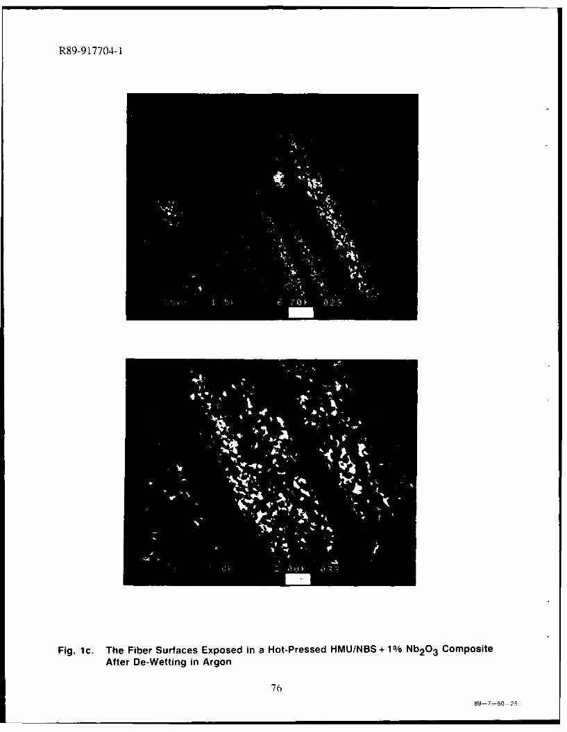
R89-9 17704-1
Fig. 1c. The Fiber Surfaces Exposed in a Hot-Pressed HMU/NBS+1% N132O3 CompositeAfter De-Wetting in Argon
7689-7-50-25
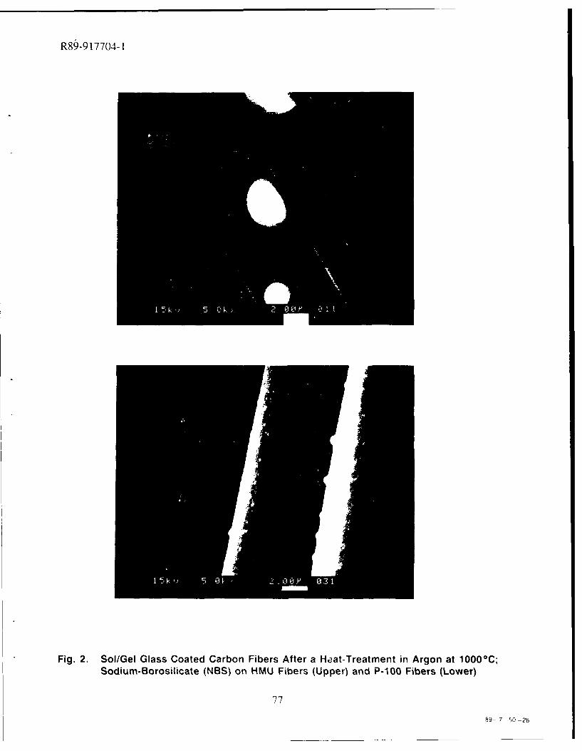
R89-9 17704- 1
* Fig. 2. Sol/Gel Glass Coated Carbon Fibers After a Heat-Treatment in Argon at 10000C;Sodium-Borosilicate (NBS) on HMU Fibers (Upper) and P-100 Fibers (Lower)
77
89- 7-50-26
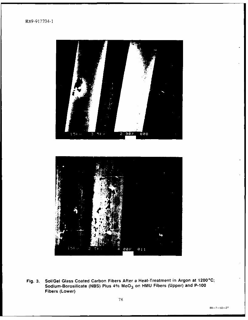
RN9-9 17704-1
. ..
Fig. 3. Sol/Gel Glass Coated Carbon Fibers After a Heat-Treatment in Argon at 12000 C;Sodium-Borosilicate (NBS) Plus 4% MoO 3 on HMU Fibers (Upper) and P-100Fibers (Lower)
78
89-7-50-27
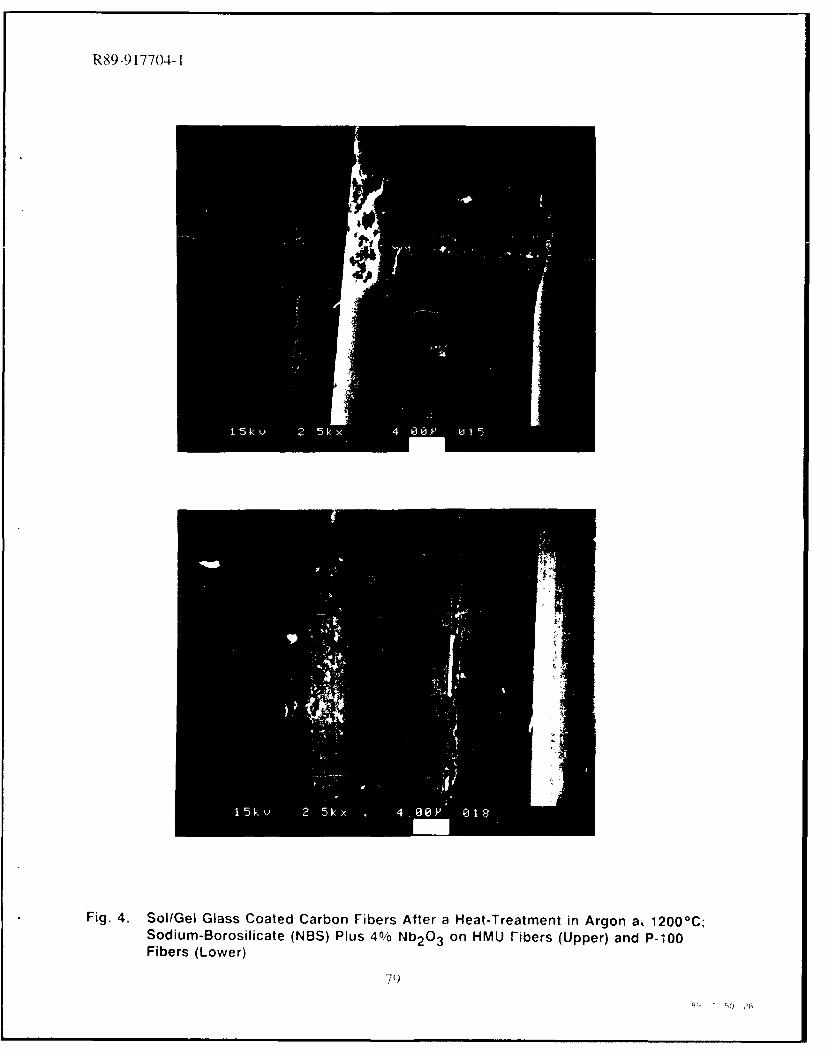
R89-9 17704-1
Fig. 4. Sol/Gel Glass Coated Carbon Fibers After a Heat-Treatment in Argon ai 12000 C;Sodium-Borosilicate (NBS) Plus 4%/ Nb 2O3 on HMU Fibers (Upper) and P-100Fibers (Lower)
79
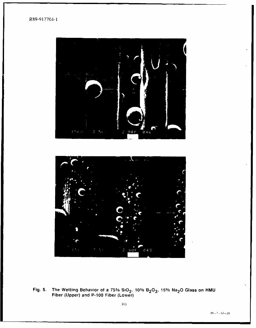
R89-9 17704-1
Fig. 5. The Wetting Behavior of a 75%/ S10 2 1 10% B203 , 15% Na2O Glass on HMUFiber (Upper) and P-100 Fiber (Lower)
X0)
89-7 -S0-29
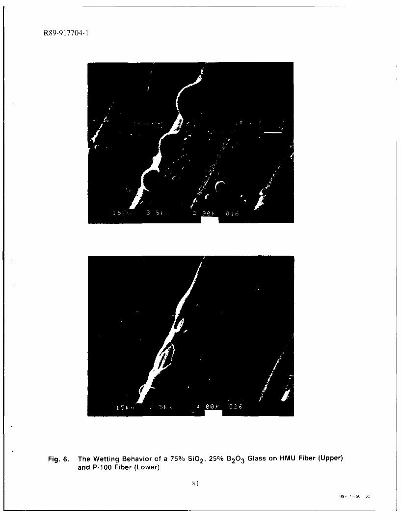
R89-9 17704-1
Fig. 6. The Wetting Behavior of a 750/ SiO2 , 250/ B2 03 Glass on HMU Fiber (Upper)and P-100 Fiber (Lower)
8-7 -SC 30
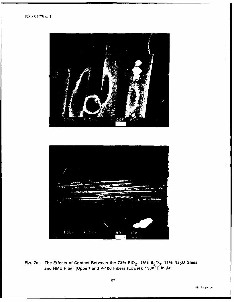
R89-9 17704-1
Fig. 7a. The Effects of Contact Between the 730,' SiO2, 16% B0,11% Na2O Glassand HMU Fiber (Upper) and P-100 Fibers (Lower); 1300'C in Ar
8289-7-50-31
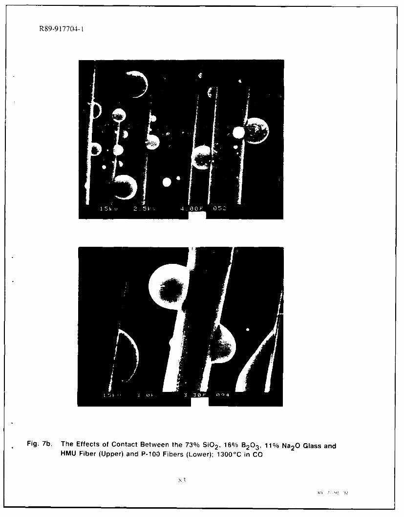
R89-917704-1
Fig. 7b. The Effects of Contact Between the 73%/ SiO2 , 160,% B2 03 , 11 % Na2O Glass andHMU Fiber (Upper) and P-100 Fibers (Lower); 13000 C in CO
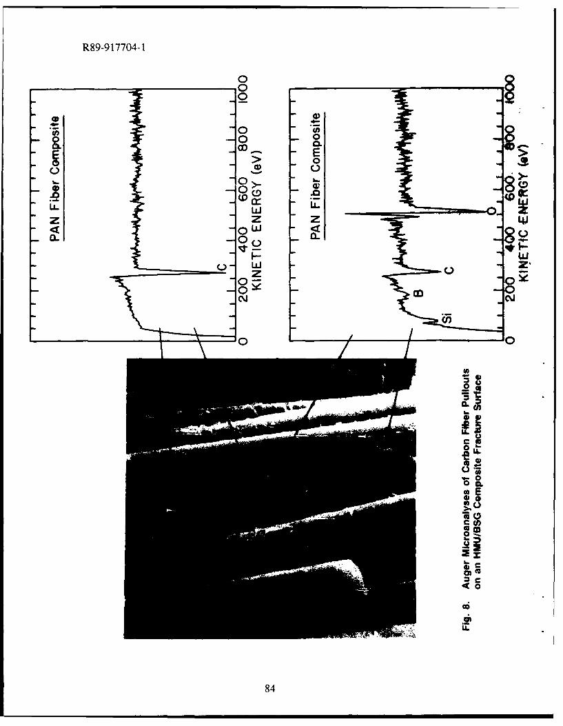
R89-9 17704-1
0 a0-0-
000.
E >> 0
C.) 0
(D .
ow
w
8446
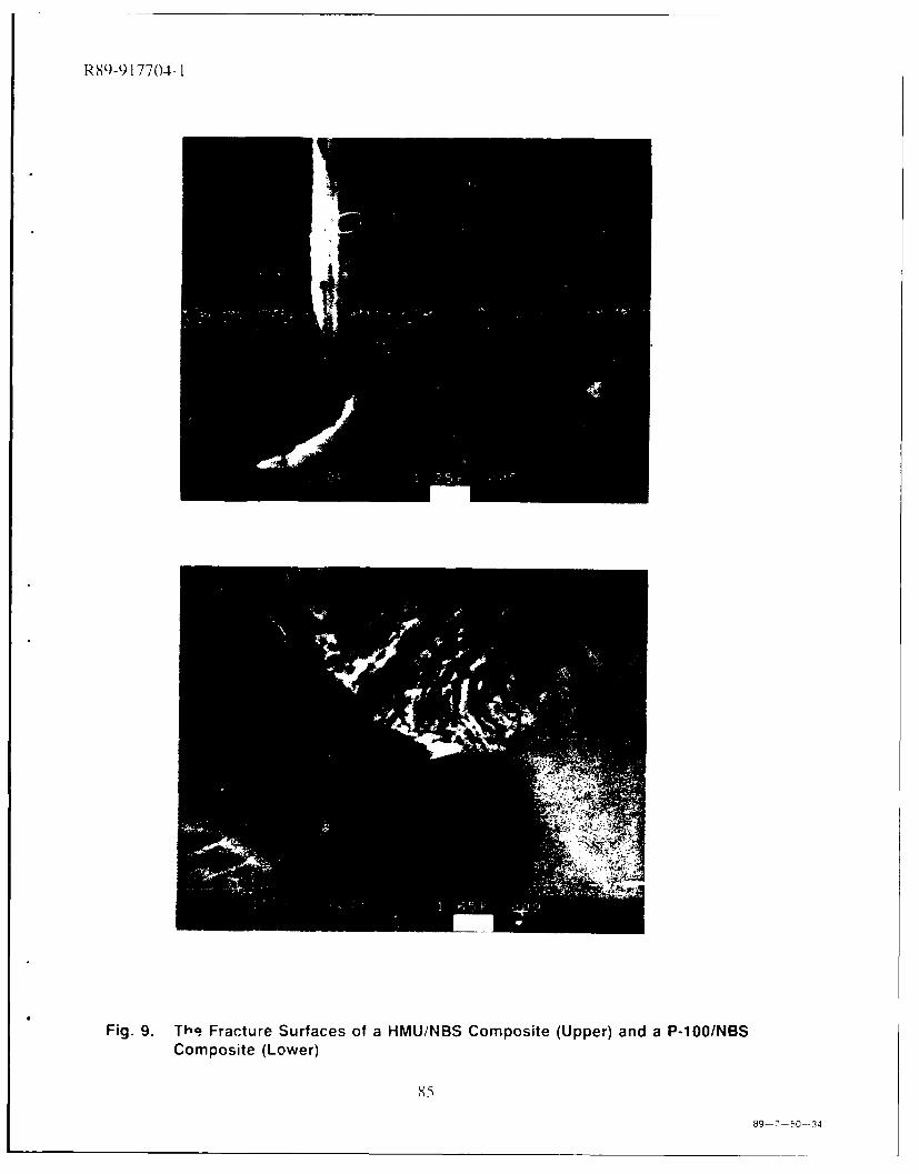
R89-917704-1
Fig. 9. Th,? Fracture Surfaces of a HMU/NBS Composite (Upper) and a P-100/NBSComposite (Lower)
85
89-7-50-34
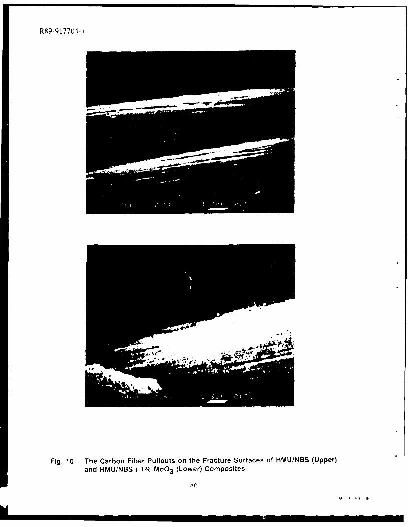
R89-917704-1
Fig. 10. The Carbon Fiber Pullouts on the Fracture Surfaces of HMU/NBS (Upper)and HMU/NBS + 1 O/ MoO 3 (Lower) Composites
86
R9- 50 (
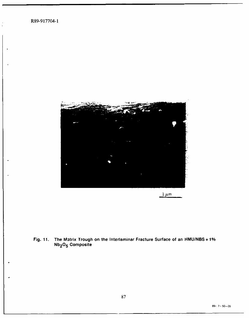
R89-9 17704-1
I jm
Fig. 11. The M3trix Trough on the Interlaminar Fracture Surface of an HMU/NBS + 1 %Nb2O5 Composite
87
89-7-50-35
R89-917704-1
VIII. SOL/GEL PROCESSING OF OXYCARBIDE GLASSESAND GLASS MATRIX COMPOSITES
H. Zhang and C. G. PantanoDepartment of Materials Science and Engineering
The Pennsylvania State UniversityUniversity Park, PA 16802
A. Introduction
In earlier studies, the thermochemical interactions between carbon fibers and silicate glassmatrices were evaluated [1]. It was found that at high temperatures, the predominant reactionsbetween the glass matrix and carbon fibers produce CO, CO2 and SiO gases. These reactions aregreatly enhanced if the glass matrix composition contains reducible oxides such as Nb20 5 orMoO3. In these cases, it could be shown that significant degradation of the fiber surfaces occurs,and moreover, solid phase reaction products including Nb-carbide and Mo-carbide eventually format the interface [2]. If excessive, these interphases lead to a measurable increase in the interfacia!shear strength, and correspondingly, a decrease in the strength and fracture toughness of thecomposite.
On the basis of these observations, it is proposed that the interface reactions can be limitedif chemically-reduced glass matrices are used in the composite fabrication; that is, glasses whoseredox potential has been equilibrated with carbon. In this way, a great deal of latitude would existin the time and temperature schedule for composite processing. Moreover, the high temperaturestrength of the composite could - for a variety of reasons - be improved. The limited interfacereactivity should prevent degradation of the fibers during service at elevated temperatures. Also,the carbon-coating glass matrix would oxidize to a degree, and thereby, limit the oxidation rate ofthe fibers. And finally, the presence of carbon and/or carbide in the glass matrix will reduce thecrystallization rate of the glass. In general, though, the ability to control the interfaces through theredox potential of the glass matrix phase would represent a new approach to tailoring the interfaceproperties in composites. One way to reduce the oxidation state of the glass is to substitute carbonfor oxygen in the silicate network; i.e., to create an oxycarbide network.
We have already developed a sol/gel method for the synthesis of ternary silicon-oxycarbide(Si-O-C) glasses [3]. The solutions are prepared using organometallic silanes which contain oneunhydrolyzable alkyl group. In this way, carbon can be retained in the gel, and most importantly,it is covalently bonded to silicon. The gel can then be processed in an inert atmosphere to create acarbon-containing x-ray amorphous black glass. In the case of Si0 2 , it has been shown that up to
88
R89-917704-1
18% carbon can be incorporated into the dense glass. 29Si magic angle spinning-nuclear magneticresonance (MAS-NMR) verifies that 50-60% of the silicon atoms in the glass are bonded directlyto one [SiCO 3/2] or two [SiC202/2] carbon atoms. 13C NMR reveals that there is also some freecarbon in the glass. But the creation of the oxycarbide network is the significant observation.Although other investigators have discussed the synthesis of carbon-containing glasses [4-71, thisstudy provided the first direct verification of Si-C ligands in the dense black glass.
The sol/gel approach is certainly advantageous, and perhaps critical, to the synthesis ofoxycarbide glass. But the gelation and hot pressing characteristics of the ternary Si-O-C systemare not yet suitable for carbon fiber reinforced composite fabrication. On the other hand, we have awell developed sol/gel method for the synthesis of borosilicate glasses and carbon fiber reinforcedborosilicate glass composites [8], and further, possess a data base of microstructural, interface andmechanical properties. Thus, it is ideally suited for evaluating the effects of carbon additions to thematrix glass composition. In this paper, the synthesis and characterization of these borosilicate/oxycarbide glasses is described, and the temperature-dependent strength behavior of carbon fiberreinforced borosilicate/oxycarbide glass composites is reported.
B. Synthesis of Glasses and Composites
The borosilicate glass is nominally of the Pyrex® (CGW 7740) composition: 81 SIO 2 ,13B-0 3, 4Na2O and 2A120 3. The alkoxide precursors used in the sol/gel syntheses of the oxideglass are tetramethoxysilane (TMOS), trimethyborate, aluminum sec-butoxide and sodium acetate.In the oxycarbide, carbon is introduced by replacing one-half of the tetra-methoxysilane withmethyl-trimethoxysilane. An equimolar mixture of these two silanes are hydrolyzed for two hoursat 60'C in methanol which contains one-third the water required for complete hydrc,.ysis of theinethoxy groups. Subsequently, stepwise additions of the B, Al and Na precursor- are added.Then, an excess of water is introduced to drive the hydrolysis to completion. The resultingsolution is clear and is typically of pH 5. The gelation of this solution requires about four hours at80'C. They are aged and dried further at 80'C to obtdtin clear, stiff gels. The black glass isobtained after a heat-treatment of the gel at 800C in argon.
Although the sol and gel can be processed to yield a glass frit for conventional compositefabrication, the solutions were used to pre-preg carbon fiber paper directly [8]. It was found thatthese solutions exhibited a strong tendency to wet and impregnate the carbon fiber paper. Thecarbon fiber paper (Celion-International Paper Co.) was cut and stacked in a mold, and then ameasured volume of solution was introduced. An independent measure of the effective glass yield(after processing the solution through to a dense glass) permits a reasonably accurate control of thevolume fraction of fiber in the final composite.
89
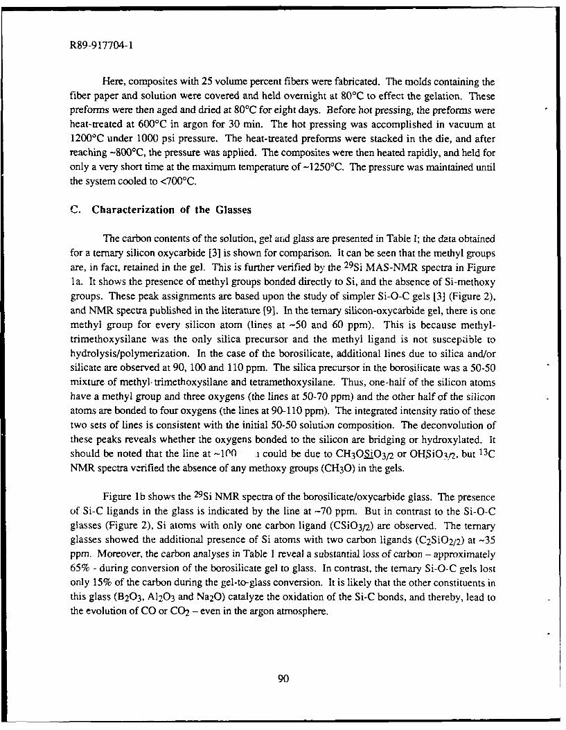
R89-917704-1
Here, composites with 25 volume percent fibers were fabricated. The molds containing thefiber paper and solution were covered and held overnight at 80°C to effect the gelation. Thesepreforms were then aged and dried at 80'C for eight days. Before hot pressing, the preforms wereheat-treated at 600'C in argon for 30 min. The hot pressing was accomplished in vacuum at1200'C under 1000 psi pressure. The heat-treated preforms were stacked in the die, and afterreaching -800'C, the pressure was applied. The composites were then heated rapidly, and held foronly a very short time at the maximum temperature of -1250'C. The pressure was maintained untilthe system cooled to <700'C.
C. Characterization of the Glasses
The carbon contents of the solution, gel aiid glass are presented in Table I; the data obtainedfor a ternary silicon oxycarbide [3] is shown for comparison. It can be seen that the methyl groupsare, in fact, retained in the gel. This is further verified by the 29Si MAS-NMR spectra in Figurela. It shows the presence of methyl groups bonded directly to Si, and the absence of Si-methoxygroups. These peak assignments are based upon the study of simpler Si-O-C gels [3] (Figure 2),and NMR spectra published in the literature [91. In the ternary silicon-oxycarbide gel, there is onemethyl group for every silicon atom (lines at -50 and 60 ppm). This is because methyl-trimethoxysilane was the only silica precursor and the methyl ligand is not suscepzible tohydrolysis/polymerization. In the case of the borosilicate, additional lines due to silica and/orsilicate are observed at 90, 100 and 110 ppm. The silica precursor in the borosilicate was a 50-50mixture of methyl- trimethoxysilane and tetramethoxysilane. Thus, one-half of the silicon atomshave a methyl group and three oxygens (the lines at 50-70 ppm) and the other half of the siliconatoms are bonded to four oxygens (the lines at 90-110 ppm). The integrated intensity ratio of thesetwo sets of lines is consistent with the initial 50-50 solution composition. The deconvolution ofthese peaks reveals whether the oxygens bonded to the silicon are bridging or hydroxylated. Itshould be noted that the line at -100 .i could be due to CH3 OSiO3/2 or OHSiOAt 2, but 13C
NMR spectra verified the absence of any methoxy groups (CH30) in the gels.
Figure lb shows the 29Si NMR spectra of the borosilicate/oxycarbide glass. The presenceof Si-C ligands in the glass is indicated by the line at -70 ppm. But in contrast to the Si-O-Cglasses (Figure 2), Si atoms with only one carbon ligand (CSi03/2) are observed. The ternaryglasses showed the additional presence of Si atoms with two carbon ligands (C2SiO2/2 ) at -35ppm. Moreover, the carbon analyses in Table I reveal a substantial loss of carbon - approximately65% - during conversion of the borosilicate gel to glass. In contrast, the ternary Si-O-C gels lostonly 15% of the carbon during the gel-to-glass conversion. It is likely that the other constituents inthis glass (B203, A120 3 and Na20) catalyze the oxidation of the Si-C bonds, and thereby, lead tothe evolution of CO or CO2 - even in the argon atmosphere.
90
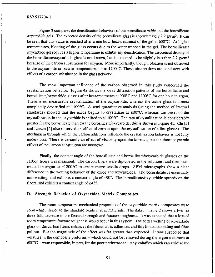
R89-917704-1
Figure 3 compares the densification behaviors of the borosilicate oxide and the borosilicateoxycarbide gels. The expected density of the borosilicate glass is approximately 2.2 g/cm3 . It canbe seen that this value is reached after a one hour heat-treatment of the gel at 650°C. At highertemperatures, bloating of the glass occurs due to the water trapped in the gel. The borosilicate/oxycarbide gel requires a highei temperature to exhibit any densification. The theoretical density ofthe borosilicate/oxycarbide glass is not known, but is expected to be slightly less than 2.2 g/cm 3
because of the carbon substitution for oxygen. More importantly, though, bloating is not observedin the oxycarbide-at least at temperatures up to 1200'C. These observations are consistent with
effects of a carbon substitution in the glass network.
The most important influence of the carbon observed in this study concerned the
crystallization behavior. Figure 4a shows the x-ray diffraction patterns of the borosilicate andborosilicate/oxycarbide glasses after heat-treatments at 900'C and 1 100°C for one hour in argon.There is no measurable crystallization of the oxycarbide, whereas the oxide glass is almostcompletely devitrified at 1100'C. A semi-quantitative analysis (using the method of internal
standards) showed that the oxide begins to crystallize at 800'C, whereas the onset of thecrystallization in the oxycarbide is shifted to >1 100'C. The rate of cystallization is considerablygreater fcr the borosilicate than for the borosilicate/oxycarbide; this is shown in Figure 4b. Chi [5]
and Larsen [6] also observed an effect of carbon upon the crystallization of silica glasses. Themechanism through which the carbon additions influence the crystallization behavior is not fullyunderstood. There is certainly an effect of viscosity upon the kinetics, but the thermodynamiceffects of the carbon substitution are unknown.
Finally, the contact angle of the borosilicate and borosilicate/oxycarbide glasses on the
carbon fibers was measured. The carbon fibers were dip-coated in the solutions, and then heat-treated in argon at -1200'C to create micro-sessile drops. SEM micrographs show a cleardifference in the wetting behavior of the oxide and oxycarbides. The borosilicate is essentiallynon-wetting, and exhibits a contact angle of -90'. The borosilicate/oxycarbide spreads on the
fibers, and exhibits a contact angle of <450.
D. Strength Behavior of Oxycarbide Matrix Composites
The room temperature mechanical properties of the oxycarbide matrix composites were
somewhat inferior to the standard oxide matrix materials. The data in Table 2 shows a two- tothree-fold decrease in the flexural strength and fracture toughness. It was expected that a loss ofroom temperature fracture toughness would occur in this system. The better wetting of oxycarbideglass on the carbon fibers enhances the fiber/matrix adhesion, and this limits debonding and fiberpullout. But the magnitude of the effect was far greater than expected. It was suspected thatvolatiles 'n the composite preforms - which could not be removed during the argon treatment at600'C - were responsible, in part, for the poor performance. Any volatiles which can oxidize the
91
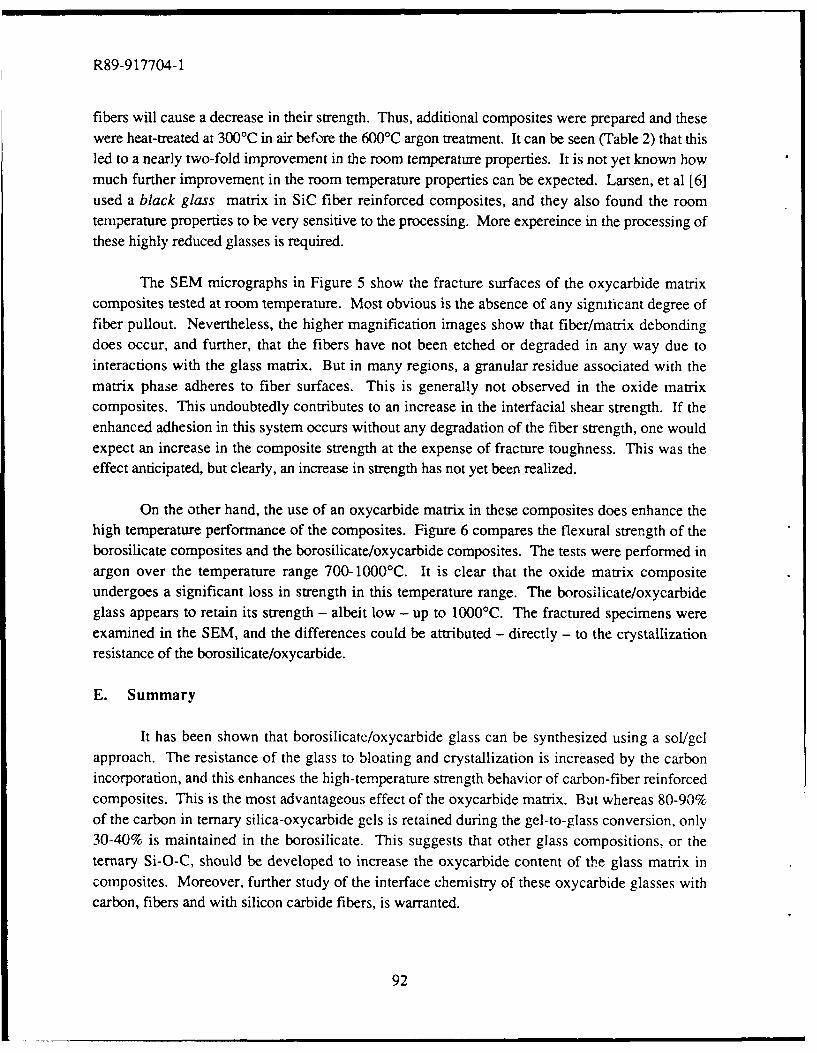
R89-917704-1
fibers will cause a decrease in their strength. Thus, additional composites were prepared and thesewere heat-treated at 300'C in air before the 600'C argon treatment. It can be seen (Table 2) that thisled to a nearly two-fold improvement in the room temperature properties. It is not yet known howmuch further improvement in the room temperature properties can be expected. Larsen, et al [6]used a black glass matrix in SiC fiber reinforced composites, and they also found the roomtemperature properties to be very sensitive to the processing. More expereince in the processing ofthese highly reduced glasses is required.
The SEM micrographs in Figure 5 show the fracture surfaces of the oxycarbide matrixcomposites tested at room temperature. Most obvious is the absence of any signiticant degree offiber pullout. Nevertheless, the higher magnification images show that fiber/matrix debondingdoes occur, and further, that the fibers have not been etched or degraded in any way due tointeractions with the glass matrix. But in many regions, a granular residue associated with thematrix phase adheres to fiber surfaces. This is generally not observed in the oxide matrixcomposites. This undoubtedly contributes to an increase in the interfacial shear strength. If theenhanced adhesion in this system occurs without any degradation of the fiber strength, one wouldexpect an increase in the composite strength at the expense of fracture toughness. This was theeffect anticipated, but clearly, an increase in strength has not yet been realized.
On the other hand, the use of an oxycarbide matrix in these composites does enhance thehigh temperature performance of the composites. Figure 6 compares the flexural strength of theborosilicate composites and the borosilicate/oxycarbide composites. The tests were performed inargon over the temperature range 700-1000C. It is clear that the oxide matrix compositeundergoes a significant loss in strength in this temperature range. The borosilicate/oxycarbideglass appears to retain its strength - albeit low - up to 1000C. The fractured specimens wereexamined in the SEM, and the differences could be attributed - directly - to the crystallizationresistance of the borosilicate/oxycarbide.
E. Summary
It has been shown that borosilicate/oxycarbide glass can be synthesized using a sol/gelapproach. The resistance of the glass to bloating and crystallization is increased by the carbonincorporation, and this enhances the high-temperature strength behavior of carbon-fiber reinforcedcomposites. This is the most advantageous effect of the oxycarbide matrix. But whereas 80-90%of the carbon in ternary silica-oxycarbide gels is retained during the gel-to-glass conversion, only30-40% is maintained in the borosilicate. This suggests that other glass compositions, or theternary Si-O-C, should be developed to increase the oxycarbide content of the glass matrix incomposites. Moreover, further study of the interface chemistry of these oxycarbide glasses withcarbon, fibers and with silicon carbide fibers, is warranted.
92
R89-917704-1
ACKNOWLEDGEMENT
The authors gratefully acknowledge the Office of Naval Research (ONR N00014-55-C-0332 and N00014-87-K-0247) for their support of this research.
REFERENCES
1. P. Benson, K. E. Spear and C. G. Pantano, "Thermochemical Analysis of Interface Reactionsin Carbon Fiber Reinforced Glass Matrix Composites," in Ceramic Microstructures '86, J. A.Pask and A. G. Evans, Eds. (Plenum, New York, 1987), pp. 415-426.
2. W. K. Tredway, K. M. Prewo and C. G. Pantano, "Fiber Matrix Interfacial Effects in CarbonFiber Reinforced Glass Matrix Composites," to appear in Carbon, 1989.
3. H. Zhang and C. G. Pantano, "Synthesis and Characterization of Si-O-C Glasses," submittedto J. Am. Ceram. Soc., 1989.
4. C. F. Smith and W. B. Crandall, "Method of Making Carbon Containing Glasses,- U.S.Patent No. 3,378,431 (1968).
5. F. K. Chi, "Carbon Containing Monolithic Glasses via the Sol/Gel Process," Ceramic Sci. and
Eng. Proc., 4, 704-717 (1983).
6. D. C. Larsen, et al., "Silicon Carbide Fiber Reinforced Black Glass Matrix Composites,"AFWAL-TR-83-4134.
7. J. Homeny and G. G. Nelson, "Oxycarbide Glasses in the Mg-AI-Si-O-C System," J. Am.Ceram. Soc., 71[5], 386-390 (1988).
8. D. Qi and C. G. Pantano, "Sol/Gel Processing of Carbon Fiber Reinforced Glass MatrixComposites," in Ultrastructure Processing of Advanced Ceramics, J. D. MacKenzie and D. R.Ulrich, Eds. (Wiley, New York, 1988), pp. 635-649.
9. J. Lipowitz, H. A. Freeman, R. T. Chen and E. R. Prack, "Composition and Structure of
Ceramic Fibers Prepared from Polymer Precursors", Advanced Ceramic Materials, 2(2), 121-128 (1987).
93
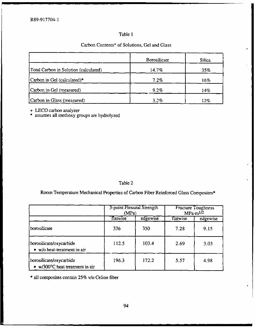
R89-917704-1
Table 1
Carbon Contents + of Solutions, Gel and Glass
Borosilicate Silica
Total Carbon in Solution (calculated) 14.7% 35%
Carbon in Gel (calculated)* 7.2% 16%
Carbon in Gel (measured) 9.2% 14%
Carbon in Glass (measured) 3.2% 12%
+ LECO carbon analyzer* assumes all methoxy groups are hydrolyzed
Table 2
Room Temperature Mechanical Properties of Carbon Fiber Reinforced Glass Composites*
3-point Flexural Strength Fracture Toughness(MPa) MPa.ml/ 2
flatwise edgewise flatwise edgewise
borosilicate 336 350 7.28 9.15
borosilicate/oxycarbide 112.5 103.4 2.69 3.03* w/o heat-treatment in air
borosilicate/oxycarbide 196.3 172.2 5.57 4.98* w/3000C heat treatment in air III
* all composites contain 25% v/o Celion fiber
94
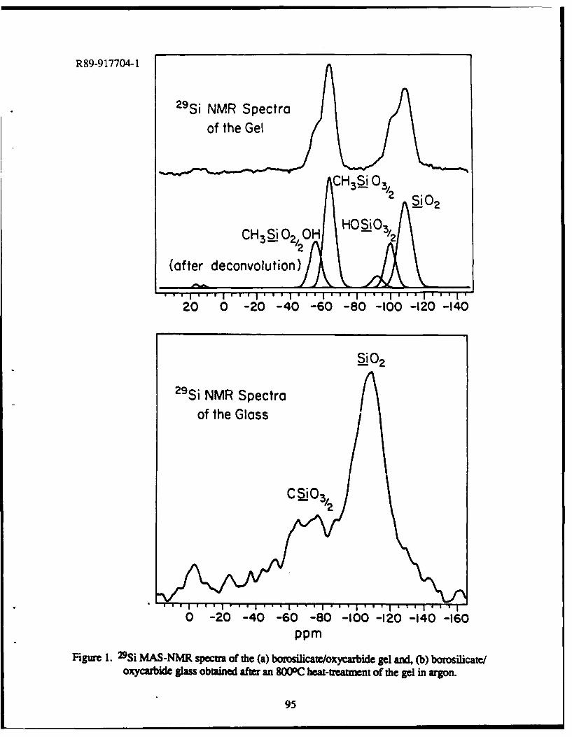
R89-9 17704-1
2-9Si NMR Spectra
of the Gel
CH3SiO2 'OHHOS3Cll i0 2 3/2
(after deconvolut ion)
.................. I~ ~
20 0 -20 -40 -60 -80 -100 -120 -140
2102
2-9Si NMVR Spectraof the Glass
C S'O 3
0 -20 -40 -60 -80 -100 -120 -140 -160PPM
Figure 1. 29Si MAS-NMR spm of the (a) boroslicate/oxycarbide gel and, (b) borosilicate/oxycarbide glass obtained after an 8000C heat-treaument of the gel in argon.
95
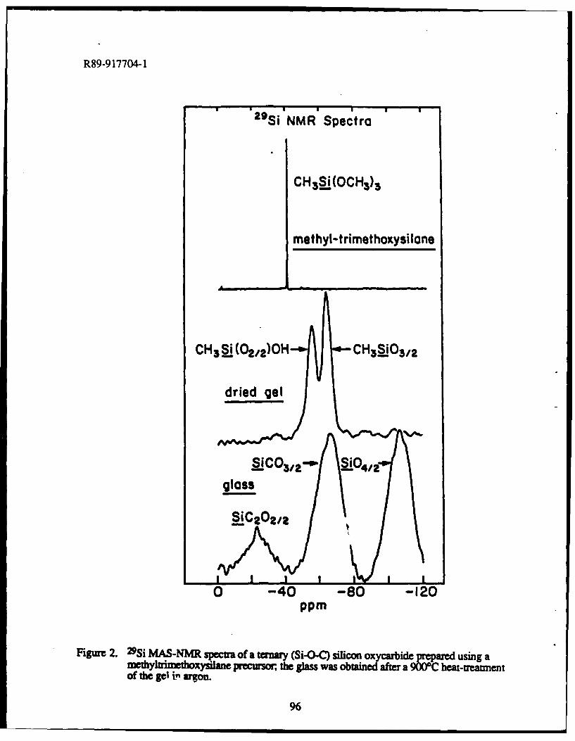
R89-9 17704-1
29S i NMR Spectra
CH3a§j(OCH 3)3
methyl-.trimethoxysi lone
CH3 ai.j(02/z) OH CH3110 3/2
dried gel
S1C0 3/ 2 ' a:4/02glass
0 -40 -80 -120
Figure 2. 29Si MAS-NMR spectra of a ternary (Si-o-C) silico xcriepeae sn
of the gel in argon.
96
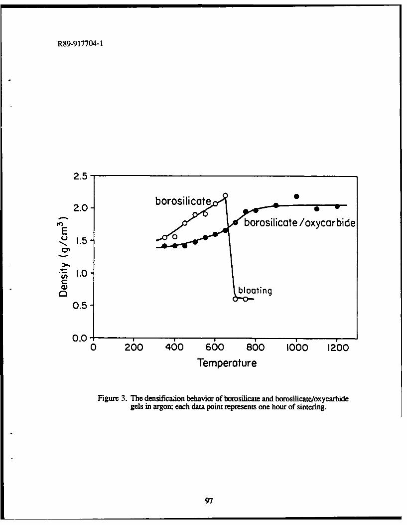
R89-9 17704-1
2.5-
2.0- borosilicateborosilicate /oxycarbide
E0
Nu- 1.0-CM
0
0.5-
0.00 260 400 600 800 10,00 1200
Temperature
Figure 3. The densificaiion behavior of borosilicate and borosilicate/oxycarbidegels in argon; each data point represents one hour of sintering.
97
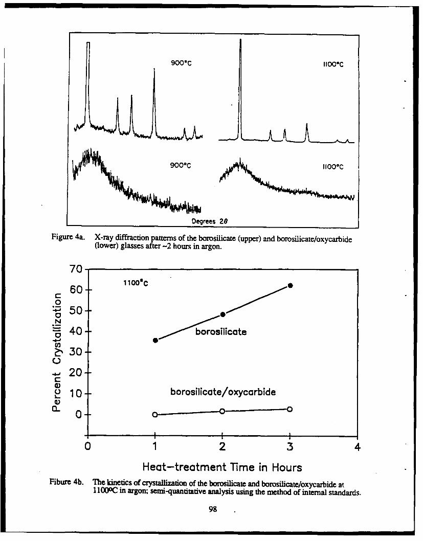
9000C IIOO*C
9000CHO
Degrees 26
]Figure 4a. X-ray diffraction patterns of the borosilicate (upper) and borosilicate/oxycarbide(lower) glasses after -2 hours in argon.
70*
60--1 0080
:50N- 40- borosilicate
U)2:%30-
00-
~ 1 0borosilicate/oxycarbide
00_
0 12 34
Heat-treatment Time in HoursFibure 4b. The inetics of crystallization of the borosilicate and borosilicate/oxycarbide at
1 I000C in argon; semi-quantitative analysis using the method of internal standards.
98
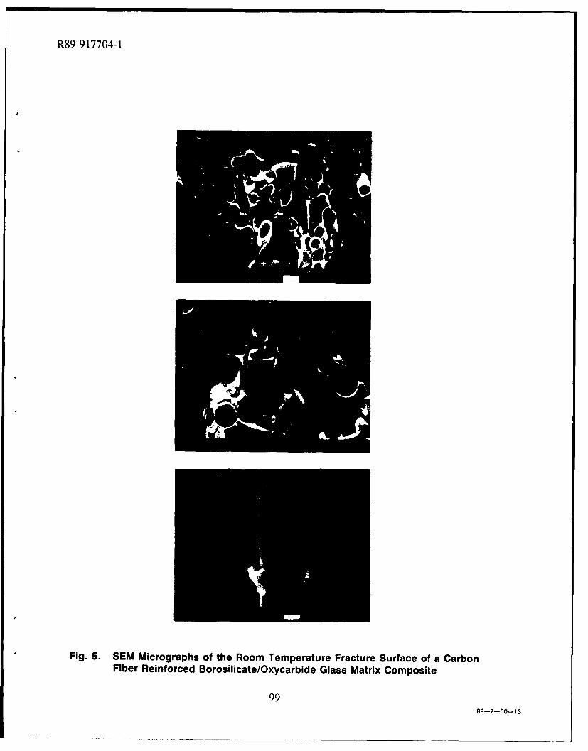
R89-917704-1
Fig. 5. SEM Micrographs of the Room Temperature Fracture Surface of a CarbonFiber Reinforced Borosilicate/Oxycarbide Glass Matrix Composite
9989-7-50-13
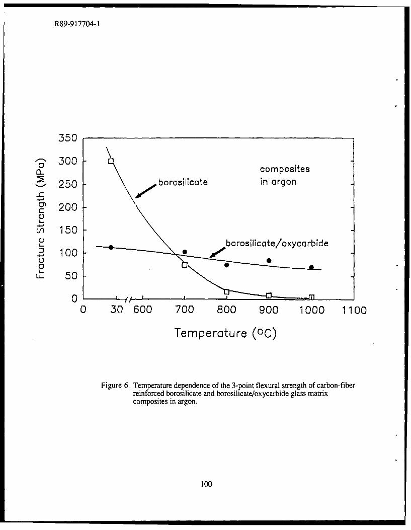
R89-9 17704-1
composites
250 -borosilicate in argon
C: 200
cn 150L. ~borosiicate/oxycorbide
42 100
50 50
00 30 600 700 800 900 1000 1100
Temperature (00)
Figure 6. Temperature dependence of the 3-point flexural strength of carbon-fiberreinforced borosilicate and borosilicate/oxycarbide glass matrixcomposites in argon.
100
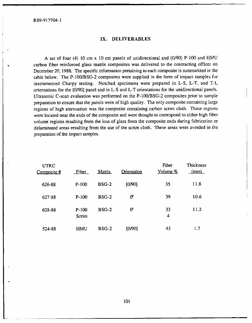
R89-917704-1
IX. DELIVERABLES
A set of four (4) 10 cm x 10 cm panels of unidirectional and [0/90] P-100 and HMUcarbon fiber reinforced glass matrix composites was delivered to the contracting officer on
December 20, 1988. The specific information pertaining to each composite is summarized in thetable below. The P-100/BSG-2 composites were supplied in the form of impact samples for
instrumented Charpy testing. Notched specimens were prepared in L-S, L-T, and T-L
orientations for the [0/90] panel and in L-S and L-T orientations for the unidirectional panels.
Ultrasonic C-scan evaluation was performed on the P-100/BSG-2 composites prior to sample
preparation to ensure that the panels were of high quality. The only composite containing large
regions of high attenuation was the composite containing carbon scrim cloth. These regions
were located near the ends of the composite and were thought to correspond to either high fiber
volume regions resulting from the loss of glass from the composite ends during fabrication ordelaminated areas resulting from the use of the scrim cloth. These areas were avoided in thepreparation of the impact samples.
UTRC Fiber Thickness
Composite # Fibe. Matrix Orientation Volume % (mm)
626-88 P-100 BSG-2 [0/90] 35 11.8
627-88 P-100 BSG-2 0' 39 10.6
628-88 P-100 BSG-2 0 33 11.2Scrim 4
524-88 HMU BSG-2 [0/90] 43 1.7
101
R89-917704-1
SUMMARY
Program Importance
The goal of this program is two-fold: (1) develop a fundamental understanding of themechanisms controlling behavior in carbon fiber reinforced glasses and glass-ceramics, and; (2)use this information to improve this family of composite materials that is superior to any other inits combination of low density, strength, stiffness, toughness, and environmental stability.Glass and glass-ceramic matrices can withstand temperatures and environmental conditions farmore severe than those tolerated by the more traditional matrices of polymers or metals. Thischaracteristic combined with the high strength, stiffness, and toughness provided by carbonfibers results in a unique high performance composite material suited for critical applications.The easy formability of the glass matrix at high temperatures also permits the fabrication of awide range of engineering shapes and sizes.
Approach
A variety of ultra-high elastic modulus pitch-based carbon fibers were combined withseveral different glass and glass-ceramic matrix compositions to produce unidirectionallyreinforced composites. Composite performance was evaluated in several different areas,including tensile stress-strain behavior, flexural properties at both room and elevatedtemperature, thermal expansion, and fracture behavior. The importance of the fiber-matrixinterface in the control of composite performance was central to the investigation.
Significant Progress
0 Glass matrix composites with high strength (540-790 MPa) and high elastic modulus (300-350 GPa) and specific stiffness (135-165 x 107 cm) were fabricated by using ultra-high elasticmodulus pitch-based carbon fibers as the reinforcement. Tensile stress-strain behavior wasfound to differ somewhat from that of HMU/Glass composites, particularly with respect toproportional limit (PL) stress and strain. Cyclic testi-g revealed that there was no loss incomposite stiffness during cycles subsequent to being loaded to stress levels well above the PL,suggesting that severe matrix microcracking is not taking place at the PL. Fiber-matrix interfacialadhesion was found to be higher in composites containing pitch-based fiber relative to HMUfiber, which subsequently affected interlaminar shear strength and composite fracture behavior.This increased adhesion was believed to result primarily from the rougher surface of the pitch-based carbon fiber, with a possible contribution from the higher surface energy of pitch-basedfiber relative of HMU.
102
R89-917704-1
0 Residual matrix tensile stress (am) resulting from differential thermal contraction betweenfiber and matrix was shown to have a strong influence on composite PL behavior. Reduction of
am by altering matrix composition resulted in significantly improved PL stress and strain in pitchfiber reinforced composites.
* Pitch/Glass composites were found to exhibit fairly linear coefficient of thermal expansion(CTE) behavior in the longitudinal direction over the temperature range of -150 0C to +100 0C,varying from approximately -0.75 ppmPC to -1.0 ppm/0 C. This CTE behavior was reproducibleover several thermal cycles. The thermal strain behavior exhibited a hysteresis of less than 25ppm over the entire thermal cycle.
* High temperature matrix compositions were developed which maintained the excellenttensile properties of pitch fiber reinforced composites while giving them the capability to preservestructural integrity up to temperatures of at least 800'C. The compositions providing the bestcomposite mechanical properties were a high-SiO 2 glass and a glass-ceramic in the BMASsystem.
* Composition was found to have a strong influence on the wetting behavior of glasses oncarbon fibers. Gaining an awareness of the factors controlling wetting is important inunderstanding the influence of fiber-matrix adhesion on composite behavior. Among borosilicateglasses, it was found that the presence of Na20 reduced the degree of wetting of carbon fibers bythe glass. Glass compositions in the SiO 2-B20 3 binary system exhibited low contact angles andsignificant spreading on carbon fibers. Wetting behavior was also found to differ among H{MUand pitch-based carbon fibers, primarily as the result of structural differences.
* A new glass system known as "oxycarbide glass" was developed using sol-gel processingtechniques. The presence of carbon in the glass network in amounts up to 3.2% was found tohave a significant effect on wetting behavior and thermal stability. Oxycarbide glassesdemonstrated enhanced wetting behavior on carbon fibers as well as resisting devitrification attemperatures as high as I 100'C.
Future Plans
Work conducted on Contract N00014-85-C-0332 has been comple!ted. Additional studieson the development of carbon fiber reinforced glass for structural applications in space arecurrently being performed on ONR Contract N00014-89-C-0046. This program is designed toenhance the readiness of C/Glass composites for implementation into structural components forspace based systems, with particular emphasis on the use of high specific stiffness compositematerials.
103
R89-917704-1
Acknowledgements
The authors gratefully acknowledge the support of the Innovative Science and Technologybranch of the Straegic Defense Initiative Organization through the Office of Naval Research(Contract N00014-85-C-0332) with Dr. Steven Fishman as the contract monitor. They wouldalso like to recognize Mr. William Kelley for composite fabrication, Ms. Judy Whitehead forcarrying out for the SEM portions of the investigation, and the Mechanical Testing group atUTRC for performing the tensile and flexural testing.
104