capacitive sensors - bibus ses srlcapacitive sensors detect the change in capacitance of an object...
TRANSCRIPT

Contents
4.1
CapacitiveSensors
– Non-contacting
– Wear-free– Non-interfering– LED function indicator– Detects virtually any
material
– Detects objects throughmany other non-metallicmaterials
– Detects aqueous media
Capacitive sensorsdetect the change incapacitance causedby the approach of an
object. Their advantagelies in the ability todetect virtually anymaterial, from metalsto oils.
4.2 Principles,Definitions
4.4 Installation4.5 Conductance values,
function areas4.6 Applications4.8 DC M8, ∅ 10 mm,
M124.9 DC M12, M18
4.10 DC M304.11 DC M344.12 AC/DC M18, M30,
∅ 34 mm4.13 DC Block style
housings4.14 Dynamic function
diagnostics4.15 DC ∅ 20 mm4.16 DC M12 with sensor
amplifier
4
Capacit
ive S
ensors

A capacitor
The sensor electrode
In capacitive sensors
Non-conducting materials
... in its traditional formconsists of two electrodeplates and a dielectric, witha non- or poorly conducting
medium in between.Capacitance C = ε (A/d) isdetermined by surface A,
distance d, andthe dielectric constant
ε ε ε ε ε = (εεεεε0 × εεεεεr).....ε describes the dielectric
constant of this medium.
ε0 is the absolute dielectricconstant of the emptyspace (vacuum).
εr is the dielectric number,
a (density dependent)material constant.
is an additional, highly
conducting, folded“intermediary electrode” Zhaving thickness D → 0.A voltage applied generatesan electrical field between
A1 and A2. This impressesvoltage U/2 in electrode Z.The “intermediate electrode”thereby assumes thefunction of an additional
capacitor plate. Thishas the effect of changingthe capacitor into twogeometrically and electricallyseries-connected capacitors.
If these partial capacitors are
unfolded, plates A1 and A2 lie
next to each other in a planeand the “intermediate”electrode in a second planeat distance d/2.This results in an “open”
capacitor. The fields inthe capacitor halves run inopposite directions.
... and its effect can be
explained using a step-by-step derivation of itsgeometric shape. The strayfields at the edges of theplates can be ignored for
these purposes.In the middle, between thetwo circular capacitor platesA1 and A2 at distance d/2,
... this „open“ capacitoris used as a sensor element.
The plate A2, however, isconfigured as a ringelectrode (housing)concentric to A1 in order tomake the electrical field
symmetrical, and the „inter-mediate electrode“ is the„actuation element“. The„sensing face“ of this sensorelement corresponds to ring
electrode A2.
Capacitance C as a functionof the distance still
decreases hyperbolically (as1/d).
The formula for capacitanceremains – with the abovedefined premises – valid
even for this capacitorgeometry.
... (Plastics, glass as wellas liquids) can be detected
by capacitive sensors, if εr issignificantly greater than ε0;The preceding is basedon the fact that for the linesof field, the path of least
resistance leads across theactuation element. If the
actuation element (d → ∞;εr = 1, C → 0) is absent,
they run in an arc from themiddle to the ringelectrode.The path of leastresistance is determinedby the repelling effect of field
lines oriented in the samedirection.
The arcs and their distancesthus become larger towards
the outside.
Principles,Definitions
Actuating element
Sensing face
4.2
CapacitiveSensors

If an electrically non-conducting actuationelement (target) enters thesensor field, the capacitance
changes proportionally
Conditions and
correction factors
Function groups
Sensing face
Standard target
Rated operating
distance sn
Effective operating
distance sr
... of a capacitive proximitysensor are:
Sensor fieldand electrode
Oscillator Demodulator Trigger Output driver
is determined mainly by thearea of the cover
and corresponds roughly tothe area of the outer sensorelectrode.
... is the area through whichthe high-frequency sensor
field enters the air space. It
Sensing face
Senso
r fie
ld
Sta
nd
ard
targ
et
... is a grounded, squareplate made of Fe 360
(ISO 630), with the switchingdistance determined perEN 60947-5-2.
The thickness is d = 1 mm;and the side length a
corresponds to– the diameter of the circle
of the “sensing face”– 3 sr, if the value is greater
than the respective
diameter.
Principles,Definitions
4.3
CapacitiveSensors
www.balluff.com
Correction factors for typical materials
... is the switching distanceof a single proximity switchmeasured under specifiedconditions such as flush
mounting, rated operatingvoltage Ue, temperatureTa = +23 °C ±5 °C.
... is a theoretical value,which does not take intoaccount manufacturing
tolerances, operatingtemperatures, supplyvoltages, etc.
For capacitive sensors, theeffective operating distancesr can be set using apotentiometer.
4
Metal 1Metal 1Metal 1Metal 1Metal 1
to εr and to the immersiondepth or to the distance tothe „sensing face“.Since the rated switching
distance sn is based on a
grounded standard targetmade of Fe 360, theswitching distances must becorrected when using other
materials.
WWWWWater 1ater 1ater 1ater 1ater 1
Glass 0.4...0.6Glass 0.4...0.6Glass 0.4...0.6Glass 0.4...0.6Glass 0.4...0.6
Ceramic 0.2...0.5Ceramic 0.2...0.5Ceramic 0.2...0.5Ceramic 0.2...0.5Ceramic 0.2...0.5
PVC 0.2...0.47PVC 0.2...0.47PVC 0.2...0.47PVC 0.2...0.47PVC 0.2...0.47
Lucite 0.39...0.45Lucite 0.39...0.45Lucite 0.39...0.45Lucite 0.39...0.45Lucite 0.39...0.45
Polycarbonate 0.26...0.4Polycarbonate 0.26...0.4Polycarbonate 0.26...0.4Polycarbonate 0.26...0.4Polycarbonate 0.26...0.4
Correction factors should be determined using the target material directly.

Installation notesCapacitiveSensors
4.4
Installation in metal
Flush mountable
proximity switches
Non-flush mountable
proximity switches
Opposing installation
of 2 sensors
... can be installed with
their sensing faces flush tothe metal.The distance between twoproximity switches (inrow mounting) must be ≥ 2d.
The sensing face mustextend ≥ 2sn from the metal-
lic installation medium.The distance between twoproximity switches must be≥ 2d.
... requires a minimumdistance of ≥ 4d betweenthe sensing face for all
inductive proximity switches.
Sensingface
Sensingface
Clear zone

Conductance values,function areas
CapacitiveSensors
4.5www.balluff.com
Level Detection
(Series R08)
– Aqueous media– Carbon– Graphite
– Acids– Blood
– Full range of
adjustment fortypical applications
– Housing wallsup to 10 mm
Standard
– Metals– Plastic granulates– Hydraulic oils
– Ceramics– Glass– PVC
– Switching distance
adjustable– Container walls
up to 4 mm
Function areas for capacitive sensors
Conductance values, adhering liquids
Pure water (semiconductor industry) 6.41E-08 ms/cm
Distilled water 1.00E-06 ms/cm
Bleach, disinfectant 140 ms/cm
Saltwater 1 percent by weight 15 ms/
cmHCL 0.1 percent by weight 10 ms/cm
Tap water 0.7 ms/cm
BCS R08...
Level detection technology 0.05 mm adhering
BCS R08...
Standard technology 0.1 mm adhering
BCS R08...Level detection technology 0.1 mm adhering
4
Whether in coolant reservoirtanks or on glass bypasstubes, the capacitive sensorreliably detects the leveland thereby helps to prevent
damage to the machinefrom running dry.
A further commonapplication is in leak
monitoring, such as onhydraulic reservoirs.

Applications
4.6
CapacitiveSensors
*No metal permitted underneath the desired object within the sensor field.
Capacitive Sensors
Capacitive sensors detectthe change in capacitance
of an object when it entersthe sensor’s electrical field.
This means a capacitivesensor can detect not
only metal, but even non-conductors whose dielectricconstants are sufficientlylarge.
Properly selected, acapacitive sensor is alsoable to “see through” certainnon-metallic materials.This makes it the classical
level detector, sensing thepresence or absence ofliquids or granular materialthrough the container wall.
Balluff also offers theappropriate cover nuts which,once installed in thecontainer, allow the capacitivesensor to be mounted and
later replaced if necessarywithout unsealing the vessel.
Inspecting paper, cloth or plasticstrips.From above or below.*
Detecting, counting objects. Inflow or pumping control in waterstorage containers.
Quality and presence sensing incigarette factory.Filter/tobacco ok?*
Inspection on packaging lines.Packaging, contents.
Level control in filling applications,controlling the reject station.

4.7
Sensing and thickness detectionof wood in secondary processing.
Packaging.Are all the ampules there?*
Checking for missing labels onthin backing.*
Guiding a knife through metalthread, e.g. for separating cloth.
Level control in plastic or glasscontainers.
Most capacitive sensorsare not designed for flush
mounting in metal.
However, the potentiometerson Balluff sensors allow theswitching distance to be
adjusted so that even flushmounting is possible.
www.balluff.com
Typical applications
Level monitoring of
– liquids– powdered and granular
materials.
Detecting and counting
parts made of– metals– plastics– glass.
4
ApplicationsCapacitiveSensors

CapacitiveSensors
DC 3-wireM8, ∅ 10 mm, M12
4.8
Housing sizeMountingRated operating distance sn
NO 1
NC 2
NO 4
NC 5
Supply voltage UB
Voltage drop Ud at IeRated insulation voltage Ui
Rated operational current IeNo-load supply current I0 max.Polarity reversal protected
Short circuit protected
Repeat accuracy RAmbient temperature range Ta
Switching frequency f
Utilization categoryFunction indicator
Degree of protection per IEC 60529
Housing materialMaterial of sensing faceConnectionNo. of wires × cross-section
Recommended connector
M12×1
flush4 mm
BCS 012-PSB-1-L-S4
12...35 V DC≤ 0.8 V
75 V DC200 mA10 mA
yes
yes
≤ 2 %–30...+70 °C
100 Hz
DC 13yes
IP 65
Stainless steelPTFE
Connector
BKS-_ 19/BKS-_ 20
∅ 10 mm
flush4 mm
BCS 010-PSB-1-L-PU-02BCS 010-POB-1-L-PU-02
12...35 V DC≤ 0.8 V
75 V DC200 mA10 mA
yes
yes
≤ 2 %–30...+70 °C
100 Hz
DC 13yes
IP 65
Stainless steelPTFE
2 m Cable PUR3×0.14 mm²
M8×1
flush1.5 mm
BCS M08EG1-PSC15C-S49G
11...30 V DC
≤ 2 V75 V DC50 mA10 mA
yes
yes
≤ 2 %–10...+70 °C
100 Hz
DC 13yes
IP 65
Stainless steelPTFE
Connector
BKS-_ 48/BKS-_ 49
M8×1
non-flush3 mm
BCS M08EG-PSC30G-S49G
11...30 V DC≤ 2 V
75 V DC50 mA10 mA
yes
yes
≤ 2 %–10...+70 °C
100 Hz
DC 13yes
IP 65
Stainless steelPTFE
Connector
BKS-_ 48/BKS-_ 49
1 Wiring diagrams see page 1.0.6
Exception: BCS M18KM3-POC80G-S04G-001For this sensor the pinout does not conform tothe standard.
NPN
PNP
Reducing sleeve
BMS AD-P-001-12/10
for sensors with ∅ 10 mmfor installing in clampsand holders with ∅ 12 mm,see page 5.65.
BCS M18KM3-POC80G-S04G-001
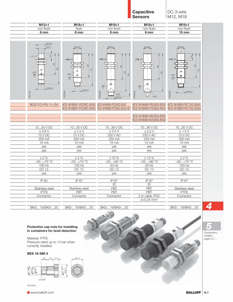
CapacitiveSensors
DC 3-wireM12, M18
4.9
Connectors,
holders ...
page 5.2 ...
5
www.balluff.com
M12×1
non-flush8 mm
BCS 012-PS-1-L-S4
12...35 V DC≤ 0.8 V
75 V DC200 mA10 mA
yes
yes
≤ 2 %–30...+70 °C
100 Hz
DC 13yes
IP 65
Stainless steelPTFE
Connector
BKS-_ 19/BKS-_ 20
M18×1
flush8 mm
BCS M18EM1-PSC80C-S04GBCS M18EM1-POC80C-S04G
10...35 V DC
≤ 1.5 V75 V DC300 mA10 mA
yes
yes
≤ 2 %–30...+70 °C
100 Hz
DC 13yes
IP 67
Stainless steelPBT
Connector
BKS-_ 19/BKS-_ 20
M18×1
non-flush8 mm
BCS M18KM3-PSC80G-S04GBCS M18KM3-POC80G-S04G-001
10...36 V DC≤ 2.5 V
250 V AC250 mA15 mA
yes
yes
≤ 10 %–25...+80 °C
50 Hz
DC 13yes
IP 67
PBTPBT
Connector
BKS-_ 19/BKS-_ 20
M18×1
non-flush8 mm
BCS M18KM3-PSC80G-BV02BCS M18KM3-POC80G-BV02
BCS M18KM3-NSC80G-BV02BCS M18KM3-NOC80G-BV02
10...36 V DC
≤ 2.5 V250 V AC250 mA15 mA
yes
yes
≤ 10 %–25...+80 °C
50 Hz
DC 13yes
IP 67
PBTPBT
2 m cable, PVC3×0.34 mm²
Protective cap nuts for installing
in containers for level detection
Material: PTFEPressure rated up to 13 bar whencorrectly installed.
BES 18-SM-3
M18×1
non-flush15 mm
BCS M18EM-PSC15G-S04GBCS M18EM-POC15G-S04G
10...35 V DC≤ 1.5 V
75 V DC300 mA10 mA
yes
yes
≤ 2 %–30...+70 °C
100 Hz
DC 13yes
IP 67
Stainless steelPTFE
Connector
BKS-_ 19/BKS-_ 20 4

4.10
CapacitiveSensors
DC 3-/4-wireM30
M30×1.5
non-flush15 mm
BCS M30KN2-PSC18G-AV02BCS M30KN2-POC15G-AV02
BCS M30KN2-NSC18G-AV02BCS M30KN2-NOC15G-AV02
10...36 V DC
≤ 2.5 V250 V AC250 mA15 mA
yesyes
≤ 10 %–25...+70 °C
40 HzDC 13
yes
IP 65
PBTPBT
2 m cable, PVC3×0.5 mm²
M30×1.5
flush20 mm
BCS M30EM2-PSC20C-S04K
10...35 V DC≤ 1.8 V75 V DC300 mA15 mA
yesyes
≤ 5 %–30...+70 °C
100 HzDC 13
yes
IP 67
Stainless steelPBT
Connector
BKS-_ 19/BKS-_ 20
1 Wiring diagrams see page 1.0.6Exception: BCS M30KM7-PPH15G-S04U
Factory setting: Normally open. The sensorcan be converted to normally closed. Oncedone, however, this cannot be reversed.
M30×1.5
non-flush15 mm
BCS M30KM7-PPH15G-S04U
10...36 V DC
≤ 2.5 V250 V AC250 mA16 mA
yesyes
≤ 10 %–25...+70 °C
40 HzDC 13
yes
IP 65
PBT/PCPBT
Connector
BKS-_ 19/BKS-_ 20Connector orientation
rotatable by 90°
BCS M30KM7-PPH15G-S04U
Housing sizeMountingRated operating distance sn
NO 1
NC 2
NO/NC
NO 4
NC 5
Supply voltage UB
Voltage drop Ud at IeRated insulation voltage Ui
Rated operational current IeNo-load supply current I0 max.
Polarity reversal protectedShort circuit protected
Repeat accuracy RAmbient temperature range Ta
Switching frequency fUtilization categoryFunction indicator
Degree of protection per IEC 60529
Insulation classHousing materialMaterial of sensing faceConnectionNo. of wires × cross-section
Recommended connector
PNP
NPN
M30×1.5
non-flush30 mm
BCS M30EG2-PSC30G-S04K
10...35 V DC
≤ 1.8 V75 V DC300 mA15 mA
yesyes
≤ 5 %–30...+70 °C
100 HzDC 13
yes
IP 67
Stainless steelPTFE
Connector
BKS-_ 19/BKS-_ 20

4.11
CapacitiveSensors
DC 3-wire∅ 34 mm
Connectors,
holders ...
page 5.2 ...
5
www.balluff.com
∅ 34 mm
non-flush20 mm
BCS G34KN2-PSC24G-AV02BCS G34KN2-POC20G-AV02
BCS G34KN2-NSC24G-AV02BCS G34KN2-NOC20G-AV02
10...36 V DC≤ 2.5 V
250 V AC250 mA13 mA
yesyes
≤ 10 %–25...+70 °C
40 HzDC 13
yes
IP 65
PBTPBT
2 m cable, PVC3×0.5 mm²
Mounting cuff includedin scope of delivery!
Protective cap nuts for installing
in containers for level detection
Material: PTFEPressure rated up to 13 bar whencorrectly installed.
BES 30-SM-3
4

CapacitiveSensors
AC/DC 2-wireM18, M30, ∅ 34 mm
4.12
Housing sizeMountingRated operating distance sn
NONC
Rated operational voltage Ue
Supply voltage UB
Voltage drop Ud at IeRated insulation voltage Ui
Rated operational current IeMinimum operating current Im
Off-state current IrInrush current Ik t ≤ 20 msPolarity reversal protected
Short circuit/overload protected
Repeat accuracy RAmbient temperature range Ta
Switching frequency f
Utilization categoryFunction indicator
Degree of protection per IEC 60529Insulation class
Housing materialMaterial of sensing faceConnectionNo. of wires × cross-section
Other cable lengths on request.
Wiring diagrams
∅ 34 mm
non-flush20 mm
BCS G34KN2-UST20G-AV02BCS G34KN2-UOT20G-AV02
110 V AC20...250 V AC/DC
≤ 6 V250 V AC
250 mA (AC)
5 mA≤ 2.5 mA at 250 V AC
≤ 1.5 A/≤ 0.5 Hzno
no/no
≤ 10 %–25...+70 °C
25 Hz (AC)/50 Hz (DC)
AC 140/DC 13yes
IP 65
PBTPBT
2 m cable, PVC2×0.5 mm²
M18×1
non-flush8 mm
BCS M18KM3-UST80G-BV02BCS M18KM3-UOT80G-BV02
110 V AC20...250 V AC/DC
≤ 6 V250 V AC
350 mA (AC)/100 mA (DC)4 mA
≤ 2.5 mA at 250 V AC≤ 2.1 A/≤ 0.5 Hz
no
no/no
≤ 10 %–25...+80 °C
25 Hz (AC)/50 Hz (DC)
AC 140/DC 13yes
IP 67
PBTPBT
2 m cable, PVC2×0.34 mm²
M30×1.5
non-flush15 mm
BCS M30KN2-UST15G-AV02BCS M30KN2-UOT15G-AV02
110 V AC20...250 V AC/DC
≤ 6 V250 V AC
250 mA (AC)
5 mA≤ 2.5 mA at 250 V AC
≤ 1.5 A/≤ 0.5 Hzno
no/no
≤ 10 %–25...+70 °C
25 Hz (AC)/50 Hz (DC)
AC 140/DC 13yes
IP 65
PBTPBT
2 m cable, PVC2×0.34 mm²
NO NC
Note
With these AC/DC sensorsuse a miniature fuse as perthe technical data sheet.
Recommendation: After ashort circuit, check thedevice for proper function.

DC 3-wireBlock style housings
CapacitiveSensors
Housing sizeMountingRated operating distance sn
NO 1
NC 2
Supply voltage UB
Voltage drop Ud at IeRated insulation voltage Ui
Rated operational current IeNo-load supply current I0 max.
Polarity reversal protectedShort circuit protected
Repeat accuracy R
Ambient temperature range Ta
Switching frequency fUtilization categoryFunction indicator
Degree of protection per IEC 60529
Housing materialMaterial of sensing faceConnection
Recommended connector
PNP
4.13
Connectors,
holders ...
page 5.2 ...
5
www.balluff.com
16×34×8 mm R08flush
Self-adjusting
BCS R08KE-PSCFAC-EP00,2-GS49BCS R08KE-POCFAC-EP00,2-GS49
12...30 V DC≤ 1.5 V75 V DC50 mA
≤ 10 mA
yesyes
≤ 5 %
–30...+70 °C2 Hz
DC 13yes
IP 67
PPPP
0.2 m cable (PUR) with
connectorBKS-_ 48
16×34×8 mm R08flush
8 mm
BCS R08KE-PSC80C-EP00,2-GS49BCS R08KE-POC80C-EP00,2-GS49
12...30 V DC≤ 1.5 V75 V DC50 mA
≤ 10 mA
yesyes
≤ 5 %
–30...+70 °C100 HzDC 13
yes
IP 67
PPPP
0.2 m cable (PUR) with
connectorBKS-_ 48
Level Detection
– For aqueous media with foamcompensation
– Standard application with no
adjustment– Self-compensating– Through glass or plastic
with wall thicknesses ofapprox. 2...10 mm
– Level detection – the newsolution for critical orchallenging applications withaqueous media
Level Detection
1 Wiring diagrams see page 1.0.6
Other cable lengths on request. 4
16×34×8 mm

Function principle
Proximity switches withdynamic diagnostics allow
monitoring of the sensorfunctions including the cable.
The oscillator state ischanged by means of a
pulse generator while theswitch is operating. As soonas there is any damageto the sensor head or theoscillator fails electrically,
the pulse generator can nolonger change the oscillatorstate and there are nolonger pulses on the output.
The pulse frequency isf ~ 160 Hz and the pulseduration t ~ 300 µs. Thepulse-pause ratio of t ~ 5 %is selected small enough
that the test pulses can be
filtered out by the inputfilter of a controller, or, forexample, a relay can bedirectly driven.
The information “proximityswitch damped orundamped” can thereforebe processed in the usualfashion.
Function monitoring
The test pulses and thereby
the function of the proximityswitch are monitored byadditional electronics whichsignal error-free function bymeans of a high level on the
“Status/Output” messageoutput.
Installation notes
The signal line for thefunction diagnostics unit
should be connectedas close as possible to theload RL (Point A). WhenPoint B is connected thecable segment between B
and load RL is not monitored.
Proximityswitch withfunctiondiagnostics
Processors
For this, Balluff offers afunction diagnostics unitwhich can be easily installedin a controller:
Function diagnostics unitsee page 1.5.19– BES 113-FD-1
(for 1 Sensor)
The following may beconnected:
Inductive sensors
see page 1.5.18– BES 113-356-SA6-S4
Normally open– BES 113-356-SA31-S4
Normally open
– BES 113-3019-SA1-S4Normally closed
Capacitive sensorsee page 4.15
– BCS 20MG10-XPA1Y-8B-03Complementary.
Single faults are detectedwhen monitoring for the
entire system.
Note!
The system described
here is not suitable for
systems with personal
protection.
For additional information
please request a devicedescription.
Switching threshold
undamped
Output signal
Relay output
Error
Status output
damped damped
Pulse diagram of a proximity switch with function diagnostics (NC).
Damping travel
CapacitiveSensors
Dynamicfunction diagnostics
4.14

DC 4-wire∅ 20 mm
CapacitiveSensors
∅ 20 mm
flush10 mm
BCS 20MG10-XPA1Y-8B-03
10...30 V DC
≤ 3.5 V75 V DC130 mA 1 mA10 mA
Open collectoryesyes
≤ 15 %+10...+50 °C
100 HzDC 13yes/yes
IP 63
Stainless steelEP
3 m Cable PUR4×0.25 mm²
Housing sizeMountingRated operating distance sn
complementary 3
Supply voltage UB
Voltage drop Ud at IeRated insulation voltage Ui
Rated operational current IeMinimum operating current ImNo-load supply current I0 max.Output resistance Ra
Polarity reversal protectedShort circuit protected
Repeat accuracy RAmbient temperature range Ta
Switching frequency fUtilization categoryFunction/Supply voltage indicator
Degree of protection per IEC 60529
Housing materialMaterial of sensing face
ConnectionNo. of wires × cross-section
3 Wiring diagram see page 1.0.6
PNP
4.15
Connectors,
holders ...
page 5.2 ...
5
www.balluff.com
4
Diagnostic