capacitive leakage detectors - jola · capacitive leakage detectors ... • leakage detectors for...
TRANSCRIPT
Capacitiveleakage detectors
Leckwatcher rangeLiqui-Switch range
L-Pointer range
for connection to a PLC or DDC unitor a NAMUR circuit
32-2-0A-1
Jola Spezialschalter GmbH & Co. KG Klostergartenstr. 11 • 67466 Lambrecht (Germany) Tel. +49 6325 188-01 • Fax +49 6325 6396 • www.jola-info.de
ContentsPage
Capacitive leakage detectorsfor extra low voltage SELV or PELV 32-2-2
The capacitive measuring principle 32-2-6
Capacitive plate sensors with plastic housing:Capacitive plate sensors CPE-... 32-2-7
Capacitive suspension sensors with plastic housing:Capacitive suspension sensors OWE-... 32-2-11
Capacitive suspension sensors with stainless steel housing:Capacitive suspension sensors COW-... 32-2-15
32-2-1
Subject to deviations from the diagrams and technical data.
The details in this brochure are product specification descriptions
and do not constitute assured properties in the legal sense.
The units described in this documentation may only be installed,
connected and started up by suitably qualified personnel!
32-2-2
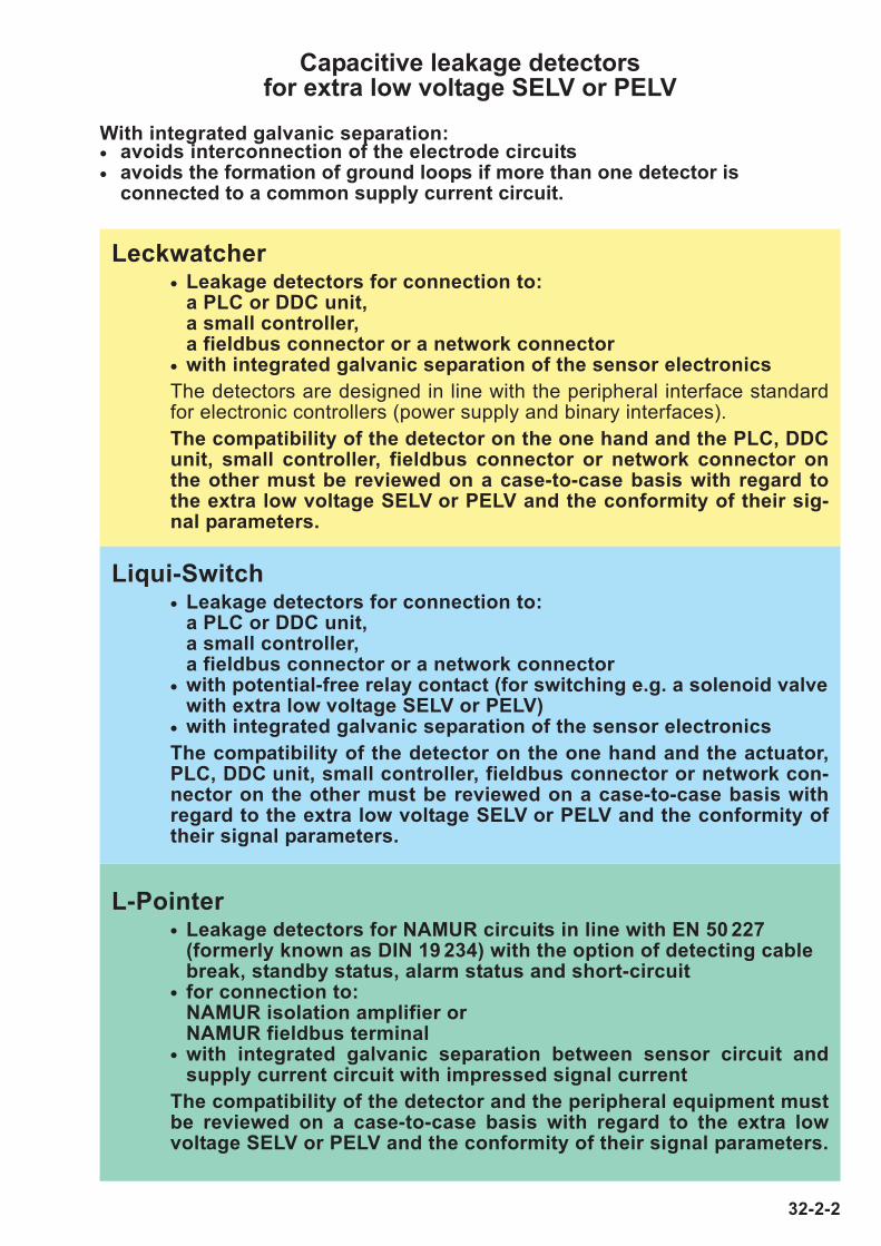
Capacitive leakage detectors for extra low voltage SELV or PELV
With integrated galvanic separation:• avoids interconnection of the electrode circuits
• avoids the formation of ground loops if more than one detector is connected to a common supply current circuit.
Leckwatcher• Leakage detectors for connection to:
a PLC or DDC unit,a small controller,a fieldbus connector or a network connector
• with integrated galvanic separation of the sensor electronics
The detectors are designed in line with the peripheral interface standardfor electronic controllers (power supply and binary interfaces).
The compatibility of the detector on the one hand and the PLC, DDCunit, small controller, fieldbus connector or network connector onthe other must be reviewed on a case-to-case basis with regard tothe extra low voltage SELV or PELV and the conformity of their sig-nal parameters.
L-Pointer• Leakage detectors for NAMUR circuits in line with EN 50 227
(formerly known as DIN 19 234) with the option of detecting cable break, standby status, alarm status and short-circuit
• for connection to: NAMUR isolation amplifier or NAMUR fieldbus terminal
• with integrated galvanic separation between sensor circuit andsupply current circuit with impressed signal current
The compatibility of the detector and the peripheral equipment mustbe reviewed on a case-to-case basis with regard to the extra lowvoltage SELV or PELV and the conformity of their signal parameters.
Liqui-Switch• Leakage detectors for connection to:
a PLC or DDC unit, a small controller,a fieldbus connector or a network connector
• with potential-free relay contact (for switching e.g. a solenoid valvewith extra low voltage SELV or PELV)
• with integrated galvanic separation of the sensor electronics
The compatibility of the detector on the one hand and the actuator,PLC, DDC unit, small controller, fieldbus connector or network con-nector on the other must be reviewed on a case-to-case basis withregard to the extra low voltage SELV or PELV and the conformity oftheir signal parameters.
32-2-3
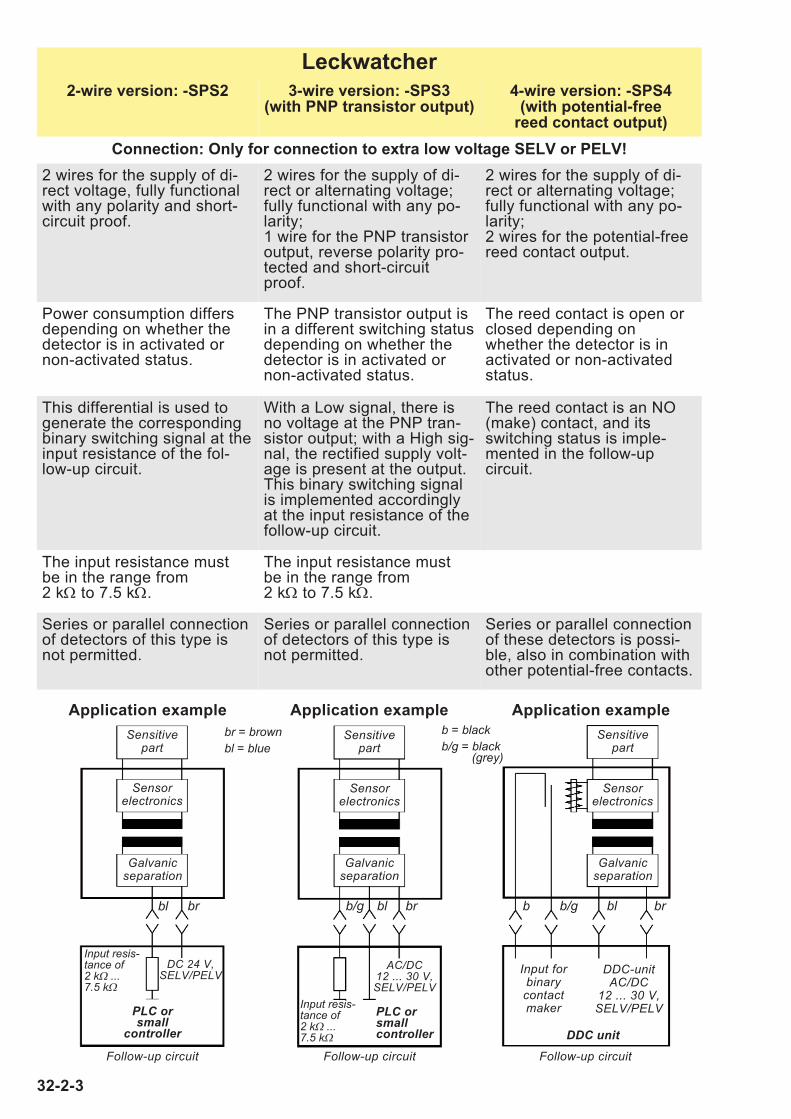
Leckwatcher
2-wire version: -SPS2 3-wire version: -SPS3(with PNP transistor output)
4-wire version: -SPS4(with potential-free
reed contact output)
Connection: Only for connection to extra low voltage SELV or PELV!
2 wires for the supply of di-rect voltage, fully functionalwith any polarity and short-circuit proof.
2 wires for the supply of di-rect or alternating voltage;fully functional with any po-larity;1 wire for the PNP transistoroutput, reverse polarity pro-tected and short-circuitproof.
2 wires for the supply of di-rect or alternating voltage;fully functional with any po-larity;2 wires for the potential-freereed contact output.
Power consumption differsdepending on whether thedetector is in activated ornon-activated status.
The PNP transistor output isin a different switching statusdepending on whether thedetector is in activated ornon-activated status.
The reed contact is open orclosed depending onwhether the detector is in activated or non-activatedstatus.
This differential is used togenerate the correspondingbinary switching signal at theinput resistance of the fol-low-up circuit.
With a Low signal, there isno voltage at the PNP tran-sistor output; with a High sig-nal, the rectified supply volt-age is present at the output.This binary switching signalis implemented accordinglyat the input resistance of thefollow-up circuit.
The reed contact is an NO(make) contact, and itsswitching status is imple-mented in the follow-up circuit.
The input resistance mustbe in the range from2 kΩ to 7.5 kΩ.
The input resistance mustbe in the range from2 kΩ to 7.5 kΩ.
Series or parallel connectionof detectors of this type isnot permitted.
Series or parallel connectionof detectors of this type isnot permitted.
Series or parallel connectionof these detectors is possi-ble, also in combination withother potential-free contacts.
Application example Application example Application example
Sensitivepart
Sensitivepart
Sensitivepart
Sensorelectronics
Sensorelectronics
Sensorelectronics
Galvanicseparation
bl bl
br = brownbl = blue
b = blackb/g = black
(grey)
br brb/g bl brb/gb
Galvanicseparation
Galvanicseparation
DDC-unitAC/DC
12 ... 30 V,SELV/PELV
Input for binary contactmaker
DDC unitFollow-up circuitFollow-up circuitFollow-up circuit
AC/DC12 ... 30 V,SELV/PELV
Input resis-tance of2 kΩ ... 7.5 kΩ
PLC orsmallcontroller
DC 24 V,SELV/PELV
Input resis-tance of2 kΩ ... 7.5 kΩ
PLC orsmall
controller
32-2-4
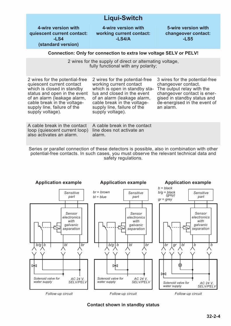
Liqui-Switch
4-wire version with
quiescent current contact:
-LS4
(standard version)
4-wire version with
working current contact:
-LS4/A
5-wire version with
changeover contact:
-LS5
Connection: Only for connection to extra low voltage SELV or PELV!
2 wires for the supply of direct or alternating voltage, fully functional with any polarity;
2 wires for the potential-freequiescent current contactwhich is closed in standbystatus and open in the eventof an alarm (leakage alarm,cable break in the voltage-supply line, failure of thesupply voltage).
2 wires for the potential-freeworking current contactwhich is open in standby sta-tus and closed in the eventof an alarm (leakage alarm,cable break in the voltage-supply line, failure of thesupply voltage).
3 wires for the potential-freechangeover contact. The output relay with thechangeover contact is ener-gised in standby status andde-energised in the event ofan alarm.
A cable break in the contactloop (quiescent current loop)also activates an alarm.
A cable break in the contactline does not activate analarm.
Series or parallel connection of these detectors is possible, also in combination with otherpotential-free contacts. In such cases, you must observe the relevant technical data and
safety regulations.
Application example Application example Application example
Contact shown in standby status
br = brownbl = blue
b = blackb/g = black
(grey)gr = grey
Sensitivepart
Sensitivepart
Sensitivepart
Sensorelectronics
with galvanic
separation
Sensorelectronics
with galvanic
separation
Sensorelectronics
with galvanic
separation
AC 24 V,SELV/PELV
AC 24 V,SELV/PELV AC 24 V,
SELV/PELV
Solenoid valve forwater supply
Solenoid valve forwater supply Solenoid valve for
water supply
bl blbr brb/g blgrbrb/gb b bb
Follow-up circuitFollow-up circuitFollow-up circuit
32-2-5
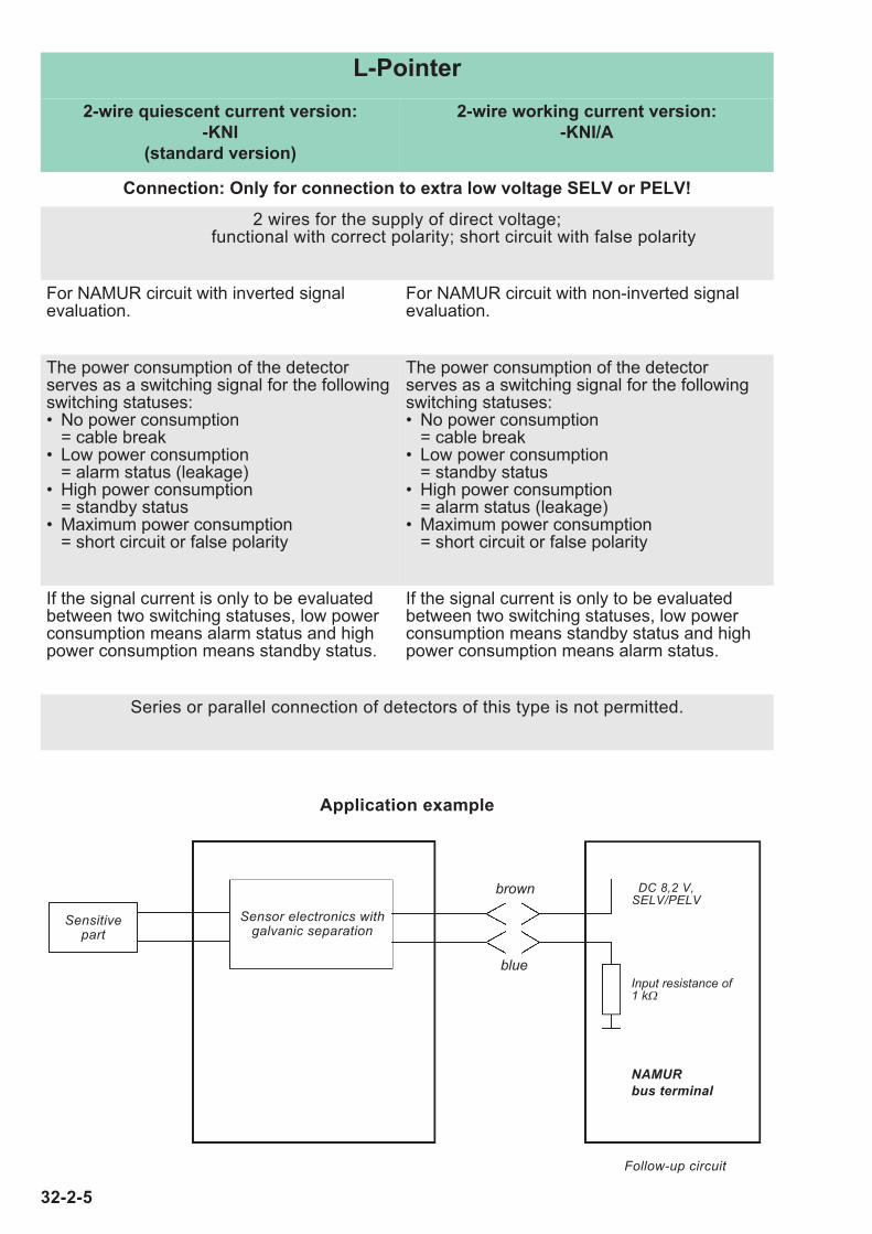
L-Pointer
2-wire quiescent current version:
-KNI
(standard version)
2-wire working current version:
-KNI/A
Connection: Only for connection to extra low voltage SELV or PELV!
2 wires for the supply of direct voltage; functional with correct polarity; short circuit with false polarity
For NAMUR circuit with inverted signal evaluation.
For NAMUR circuit with non-inverted signalevaluation.
The power consumption of the detectorserves as a switching signal for the followingswitching statuses:• No power consumption
= cable break• Low power consumption
= alarm status (leakage)• High power consumption
= standby status• Maximum power consumption
= short circuit or false polarity
The power consumption of the detector serves as a switching signal for the followingswitching statuses:• No power consumption
= cable break• Low power consumption
= standby status• High power consumption
= alarm status (leakage)• Maximum power consumption
= short circuit or false polarity
If the signal current is only to be evaluatedbetween two switching statuses, low powerconsumption means alarm status and highpower consumption means standby status.
If the signal current is only to be evaluated between two switching statuses, low powerconsumption means standby status and highpower consumption means alarm status.
Series or parallel connection of detectors of this type is not permitted.
Application example
Sensitivepart
Sensor electronics withgalvanic separation
Follow-up circuit
DC 8,2 V,SELV/PELV
blue
brown
Input resistance of1 kΩ
NAMURbus terminal
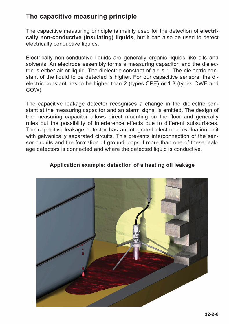
The capacitive measuring principle
The capacitive measuring principle is mainly used for the detection of electri-
cally non-conductive (insulating) liquids, but it can also be used to detect
electrically conductive liquids.
Electrically non-conductive liquids are generally organic liquids like oils and
solvents. An electrode assembly forms a measuring capacitor, and the dielec-
tric is either air or liquid. The dielectric constant of air is 1. The dielectric con-
stant of the liquid to be detected is higher. For our capacitive sensors, the di-
electric constant has to be higher than 2 (types CPE) or 1.8 (types OWE and
COW).
The capacitive leakage detector recognises a change in the dielectric con-
stant at the measuring capacitor and an alarm signal is emitted. The design of
the measuring capacitor allows direct mounting on the floor and generally
rules out the possibility of interference effects due to different subsurfaces.
The capacitive leakage detector has an integrated electronic evaluation unit
with galvanically separated circuits. This prevents interconnection of the sen-
sor circuits and the formation of ground loops if more than one of these leak-
age detectors is connected and where the detected liquid is conductive.
Application example: detection of a heating oil leakage
32-2-6
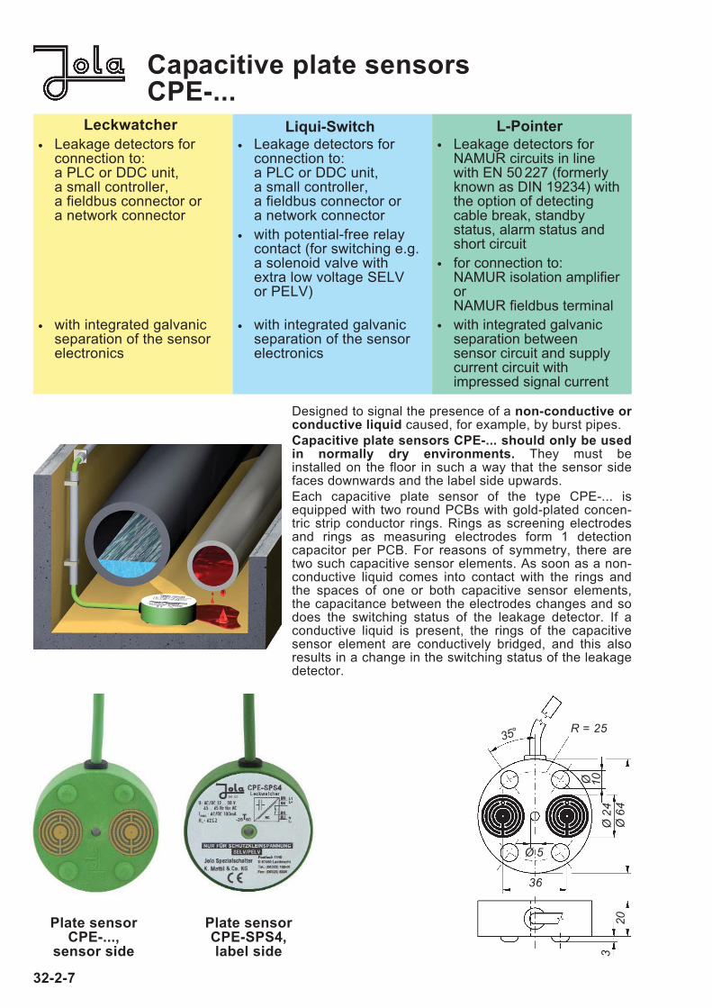
Capacitive plate sensorsCPE-...
Plate sensorCPE-SPS4,label side
Plate sensorCPE-...,
sensor side
32-2-7
Designed to signal the presence of a non-conductive orconductive liquid caused, for example, by burst pipes.
Capacitive plate sensors CPE-... should only be usedin normally dry environments. They must be installed on the floor in such a way that the sensor sidefaces downwards and the label side upwards.
Each capacitive plate sensor of the type CPE-... isequipped with two round PCBs with gold-plated concen-tric strip conductor rings. Rings as screening electrodesand rings as measuring electrodes form 1 detection capacitor per PCB. For reasons of symmetry, there aretwo such capacitive sensor elements. As soon as a non-conductive liquid comes into contact with the rings andthe spaces of one or both capacitive sensor elements,the capacitance between the electrodes changes and sodoes the switching status of the leakage detector. If aconductive liquid is present, the rings of the capacitivesensor element are conductively bridged, and this alsoresults in a change in the switching status of the leakagedetector.
36
320
Ø 2
4Ø
64
35°
Ø
10
Ø 5
R = 25
Leckwatcher
• Leakage detectors forconnection to: a PLC or DDC unit,a small controller,a fieldbus connector ora network connector
• with integrated galvanicseparation of the sensorelectronics
Liqui-Switch
• Leakage detectors forconnection to: a PLC or DDC unit,a small controller,a fieldbus connector ora network connector
• with potential-free relaycontact (for switching e.g.a solenoid valve withextra low voltage SELVor PELV)
• with integrated galvanicseparation of the sensorelectronics
L-Pointer
• Leakage detectors forNAMUR circuits in linewith EN 50 227 (formerlyknown as DIN 19234) withthe option of detectingcable break, standbystatus, alarm status andshort circuit
• for connection to: NAMUR isolation amplifierorNAMUR fieldbus terminal
• with integrated galvanicseparation between sensor circuit and supplycurrent circuit with impressed signal current
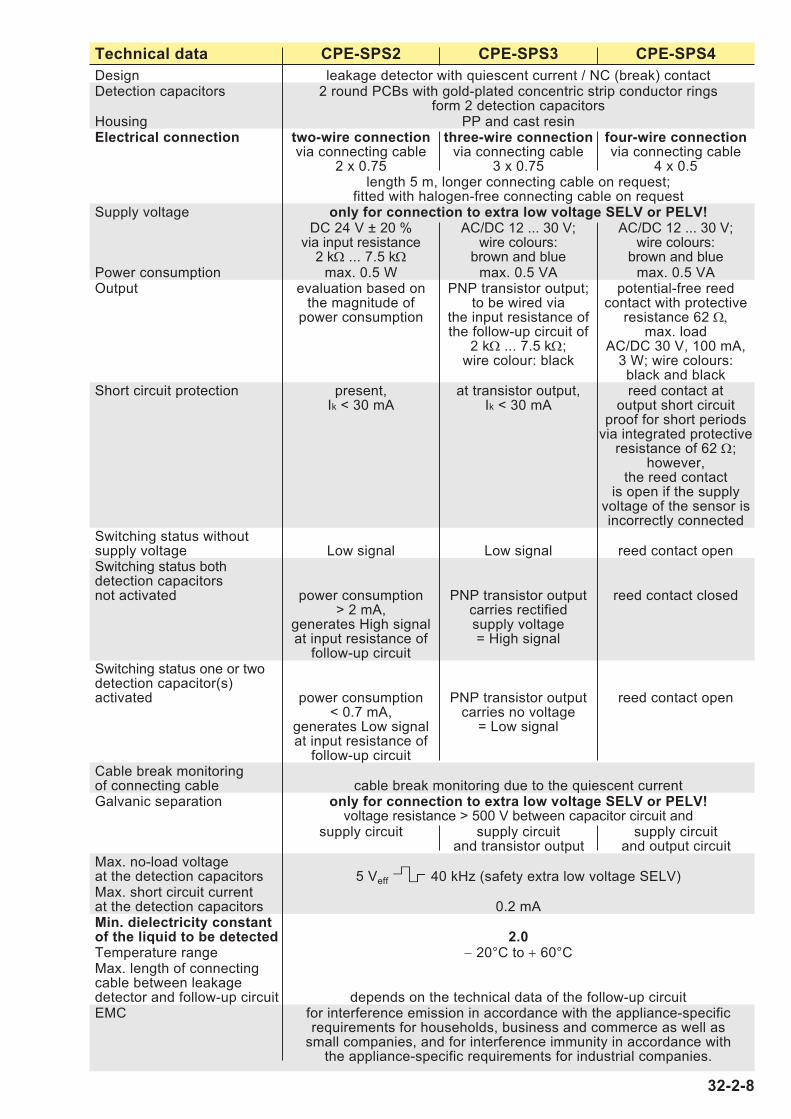
Technical data CPE-SPS2 CPE-SPS3 CPE-SPS4
Design leakage detector with quiescent current / NC (break) contactDetection capacitors 2 round PCBs with gold-plated concentric strip conductor rings
form 2 detection capacitorsHousing PP and cast resinElectrical connection two-wire connection three-wire connection four-wire connection
via connecting cable via connecting cable via connecting cable2 x 0.75 3 x 0.75 4 x 0.5
length 5 m, longer connecting cable on request;fitted with halogen-free connecting cable on request
Supply voltage only for connection to extra low voltage SELV or PELV!DC 24 V ± 20 % AC/DC 12 ... 30 V; AC/DC 12 ... 30 V;
via input resistance wire colours: wire colours: 2 kΩ ... 7.5 kΩ brown and blue brown and blue
Power consumption max. 0.5 W max. 0.5 VA max. 0.5 VAOutput evaluation based on PNP transistor output; potential-free reed
the magnitude of to be wired via contact with protectivepower consumption the input resistance of resistance 62 Ω,
the follow-up circuit of max. load2 kΩ ... 7.5 kΩ; AC/DC 30 V, 100 mA,
wire colour: black 3 W; wire colours:black and black
Short circuit protection present, at transistor output, reed contact atIk < 30 mA Ik < 30 mA output short circuit
proof for short periodsvia integrated protective
resistance of 62 Ω;however,
the reed contactis open if the supply
voltage of the sensor isincorrectly connected
Switching status withoutsupply voltage Low signal Low signal reed contact openSwitching status bothdetection capacitorsnot activated power consumption PNP transistor output reed contact closed
> 2 mA, carries rectifiedgenerates High signal supply voltageat input resistance of = High signal
follow-up circuitSwitching status one or twodetection capacitor(s)activated power consumption PNP transistor output reed contact open
< 0.7 mA, carries no voltagegenerates Low signal = Low signalat input resistance of
follow-up circuitCable break monitoringof connecting cable cable break monitoring due to the quiescent currentGalvanic separation only for connection to extra low voltage SELV or PELV!
voltage resistance > 500 V between capacitor circuit andsupply circuit supply circuit supply circuit
and transistor output and output circuitMax. no-load voltage at the detection capacitors 5 Veff 40 kHz (safety extra low voltage SELV)Max. short circuit current at the detection capacitors 0.2 mAMin. dielectricity constant of the liquid to be detected 2.0Temperature range − 20°C to + 60°CMax. length of connectingcable between leakagedetector and follow-up circuit depends on the technical data of the follow-up circuitEMC for interference emission in accordance with the appliance-specific
requirements for households, business and commerce as well assmall companies, and for interference immunity in accordance with
the appliance-specific requirements for industrial companies.
32-2-8

Technical data CPE-LS4 CPE-LS4/A CPE-LS5
Design leakage detector with relay outputDetection capacitors 2 round PCBs with gold-plated concentric strip conductor
rings form 2 detection capacitorsHousing PP and cast resinElectrical connection four-wire four-wire five-wire
connection connection connectionvia connecting cable
4 x 0.5 4 x 0.5 5 x 0.5length 5 m, longer connecting cable on request;
fitted with halogen-free connecting cable on requestSupply voltage only for connection to extra low voltage SELV or PELV!
AC/DC 24 V ± 20 %, on request AC/DC 12 V ± 20 %wire colours: wire colours: wire colours:
brown and blue brown and blue black and blackPower consumption approx. 0.5 VAOutput potential-free potential-free potential-free
quiescent current working current changeover(NC) contact (NO) contact (CO) contact
max. load AC/DC 5 ... 24 V(extra low voltage SELV or PELV only);
AC/DC 1 mA ... 3 (1) Awire colours: wire colours:
black and black (grey) brown, grey a. blueSwitching status withoutsupply voltage output relay output relay output relay
de-energised, de-energised, de-energised,output contact output contact changeover in pos. 1
open closed (grey and blue)Switching status both detection capacitors not activated output relay output relay output relay
energised, energised, energised,output contact output contact changeover in pos. 2
closed open (grey and brown)Switching status one or two detection capacitor(s) activated output relay output relay output relay
de-energised, de-energised, de-energised,output contact output contact changeover in pos. 1
open closed (grey and blue)Cable break monitoringof connecting cable cable break
monitoring due tothe quiescent
currentGalvanic separation only for connection to extra low voltage SELV or PELV!
voltage resistance > 500 V between capacitor circuit,supply circuit and output circuit
Max. no-load voltage at the detection capacitors 5 Veff 40 kHz (safety extra low voltage SELV)Max. short circuit current at the detection capacitors 0.2 mAMin. dielectricity constant of the liquid to be detected 2.0Temperature range − 20°C to + 60°CMax. length of connectingcable between leakagedetector and follow-up circuit depends on the technical data of the follow-up circuitEMC for interference emission in accordance with the appliance-
specific requirements for households, business and commerce as well as small companies, and for interference
immunity in accordance with the appliance-specific
32-2-9
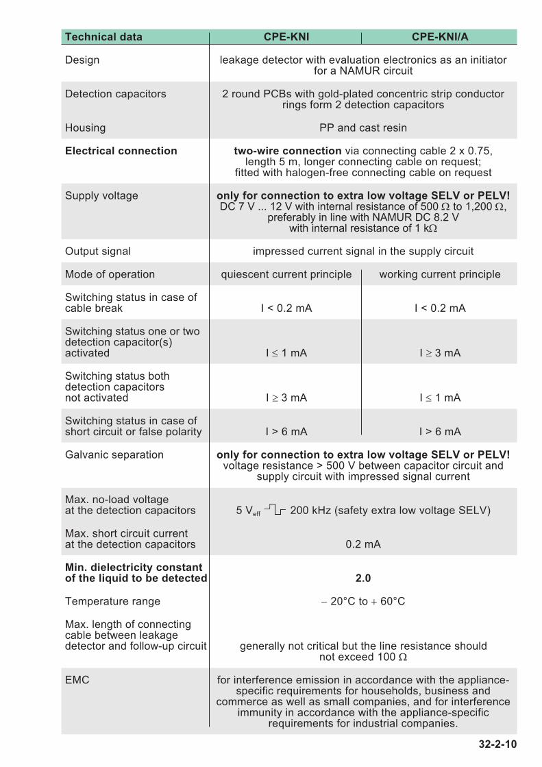
Technical data CPE-KNI CPE-KNI/A
Design leakage detector with evaluation electronics as an initiatorfor a NAMUR circuit
Detection capacitors 2 round PCBs with gold-plated concentric strip conductorrings form 2 detection capacitors
Housing PP and cast resin
Electrical connection two-wire connection via connecting cable 2 x 0.75,length 5 m, longer connecting cable on request;
fitted with halogen-free connecting cable on request
Supply voltage only for connection to extra low voltage SELV or PELV!DC 7 V ... 12 V with internal resistance of 500 Ω to 1,200 Ω,
preferably in line with NAMUR DC 8.2 Vwith internal resistance of 1 kΩ
Output signal impressed current signal in the supply circuit
Mode of operation quiescent current principle working current principle
Switching status in case ofcable break I < 0.2 mA I < 0.2 mA
Switching status one or twodetection capacitor(s)activated I ≤ 1 mA I ≥ 3 mA
Switching status bothdetection capacitorsnot activated I ≥ 3 mA I ≤ 1 mA
Switching status in case ofshort circuit or false polarity I > 6 mA I > 6 mA
Galvanic separation only for connection to extra low voltage SELV or PELV!voltage resistance > 500 V between capacitor circuit and
supply circuit with impressed signal current
Max. no-load voltage at the detection capacitors 5 Veff 200 kHz (safety extra low voltage SELV)
Max. short circuit current at the detection capacitors 0.2 mA
Min. dielectricity constant of the liquid to be detected 2.0
Temperature range − 20°C to + 60°C
Max. length of connectingcable between leakagedetector and follow-up circuit generally not critical but the line resistance should
not exceed 100 Ω
EMC for interference emission in accordance with the appliance-specific requirements for households, business and
commerce as well as small companies, and for interference immunity in accordance with the appliance-specific
requirements for industrial companies.
32-2-10
74 10
1 42
1715
761946
5063
1,51,
51,
5
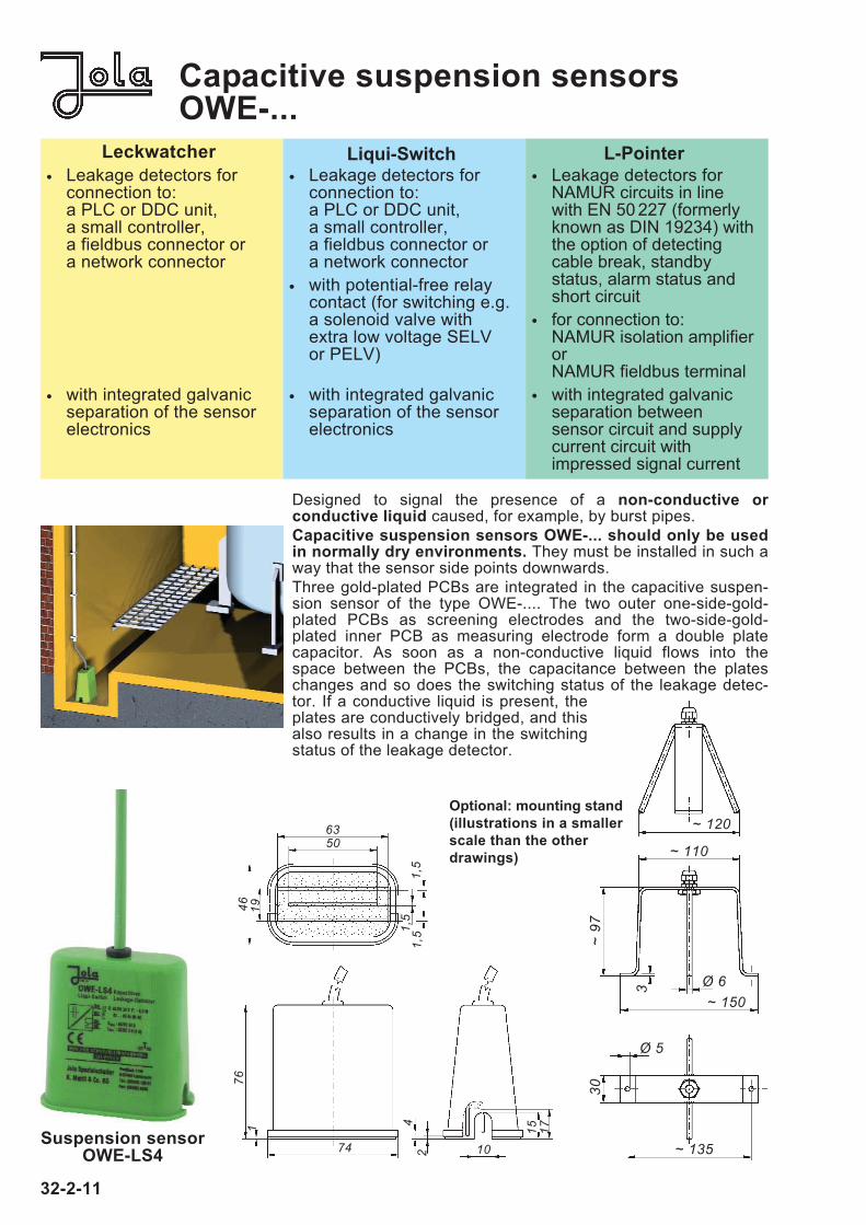
Designed to signal the presence of a non-conductive or conductive liquid caused, for example, by burst pipes.
Capacitive suspension sensors OWE-... should only be usedin normally dry environments. They must be installed in such away that the sensor side points downwards.
Three gold-plated PCBs are integrated in the capacitive suspen-sion sensor of the type OWE-.... The two outer one-side-gold-plated PCBs as screening electrodes and the two-side-gold-plated inner PCB as measuring electrode form a double plate capacitor. As soon as a non-conductive liquid flows into thespace between the PCBs, the capacitance between the plateschanges and so does the switching status of the leakage detec-tor. If a conductive liquid is present, theplates are conductively bridged, and thisalso results in a change in the switchingstatus of the leakage detector.
Capacitive suspension sensorsOWE-...
Suspension sensorOWE-LS4
~ 110
~ 120
Ø 6~ 150
3
~ 97
Ø 5
30
~ 135
Optional: mounting stand
(illustrations in a smaller
scale than the other
drawings)
32-2-11
Leckwatcher
• Leakage detectors forconnection to: a PLC or DDC unit,a small controller,a fieldbus connector ora network connector
• with integrated galvanicseparation of the sensorelectronics
Liqui-Switch
• Leakage detectors forconnection to: a PLC or DDC unit,a small controller,a fieldbus connector ora network connector
• with potential-free relaycontact (for switching e.g.a solenoid valve withextra low voltage SELVor PELV)
• with integrated galvanicseparation of the sensorelectronics
L-Pointer
• Leakage detectors forNAMUR circuits in linewith EN 50 227 (formerlyknown as DIN 19234) withthe option of detectingcable break, standbystatus, alarm status andshort circuit
• for connection to: NAMUR isolation amplifierorNAMUR fieldbus terminal
• with integrated galvanicseparation between sensor circuit and supplycurrent circuit with impressed signal current
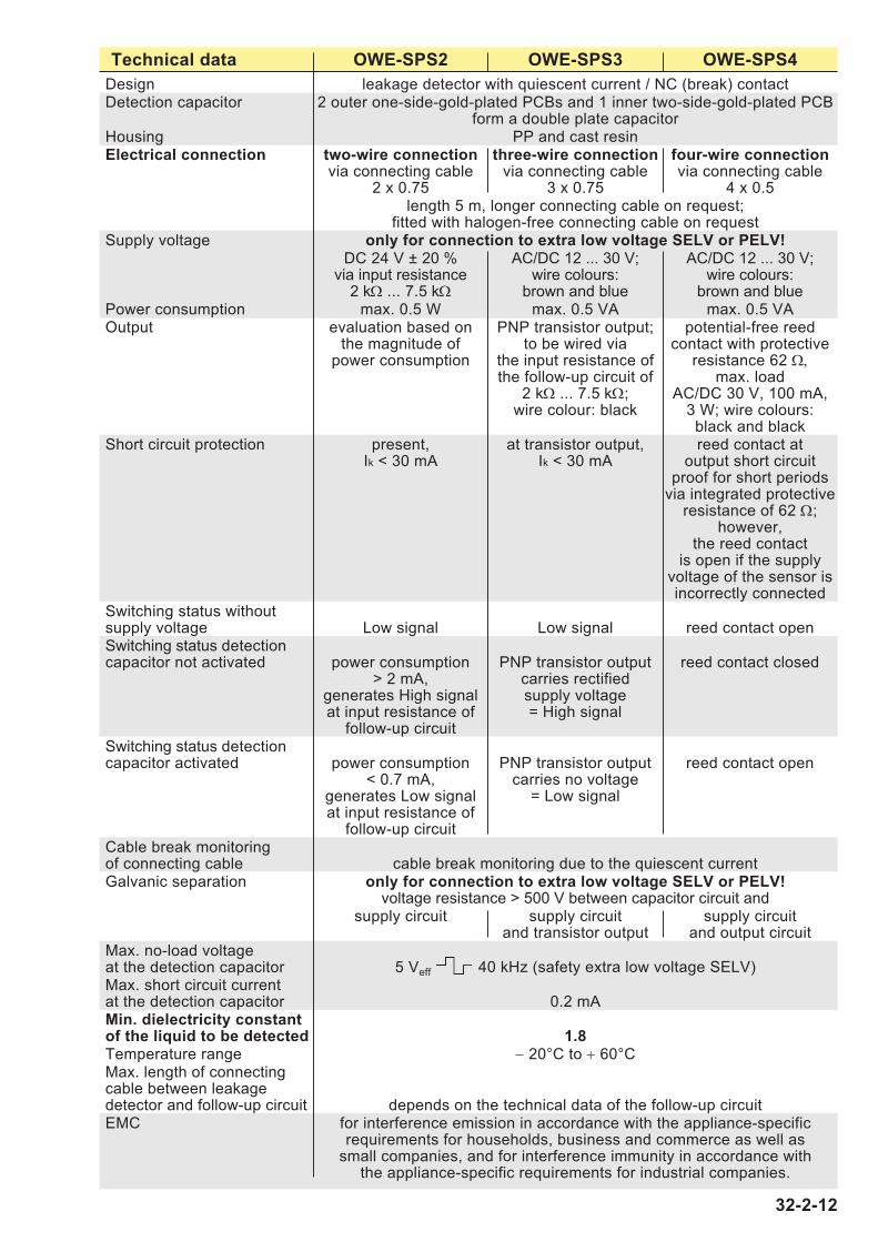
Technical data OWE-SPS2 OWE-SPS3 OWE-SPS4
Design leakage detector with quiescent current / NC (break) contactDetection capacitor 2 outer one-side-gold-plated PCBs and 1 inner two-side-gold-plated PCB
form a double plate capacitorHousing PP and cast resinElectrical connection two-wire connection three-wire connection four-wire connection
via connecting cable via connecting cable via connecting cable2 x 0.75 3 x 0.75 4 x 0.5
length 5 m, longer connecting cable on request;fitted with halogen-free connecting cable on request
Supply voltage only for connection to extra low voltage SELV or PELV!DC 24 V ± 20 % AC/DC 12 ... 30 V; AC/DC 12 ... 30 V;
via input resistance wire colours: wire colours: 2 kΩ ... 7.5 kΩ brown and blue brown and blue
Power consumption max. 0.5 W max. 0.5 VA max. 0.5 VAOutput evaluation based on PNP transistor output; potential-free reed
the magnitude of to be wired via contact with protectivepower consumption the input resistance of resistance 62 Ω,
the follow-up circuit of max. load2 kΩ ... 7.5 kΩ; AC/DC 30 V, 100 mA,
wire colour: black 3 W; wire colours:black and black
Short circuit protection present, at transistor output, reed contact atIk < 30 mA Ik < 30 mA output short circuit
proof for short periodsvia integrated protective
resistance of 62 Ω;however,
the reed contactis open if the supply
voltage of the sensor isincorrectly connected
Switching status withoutsupply voltage Low signal Low signal reed contact openSwitching status detection capacitor not activated power consumption PNP transistor output reed contact closed
> 2 mA, carries rectifiedgenerates High signal supply voltageat input resistance of = High signal
follow-up circuitSwitching status detection capacitor activated power consumption PNP transistor output reed contact open
< 0.7 mA, carries no voltagegenerates Low signal = Low signalat input resistance of
follow-up circuitCable break monitoringof connecting cable cable break monitoring due to the quiescent currentGalvanic separation only for connection to extra low voltage SELV or PELV!
voltage resistance > 500 V between capacitor circuit andsupply circuit supply circuit supply circuit
and transistor output and output circuitMax. no-load voltage at the detection capacitor 5 Veff 40 kHz (safety extra low voltage SELV)Max. short circuit current at the detection capacitor 0.2 mAMin. dielectricity constant of the liquid to be detected 1.8Temperature range − 20°C to + 60°CMax. length of connectingcable between leakagedetector and follow-up circuit depends on the technical data of the follow-up circuitEMC for interference emission in accordance with the appliance-specific
requirements for households, business and commerce as well assmall companies, and for interference immunity in accordance with
the appliance-specific requirements for industrial companies.
32-2-12
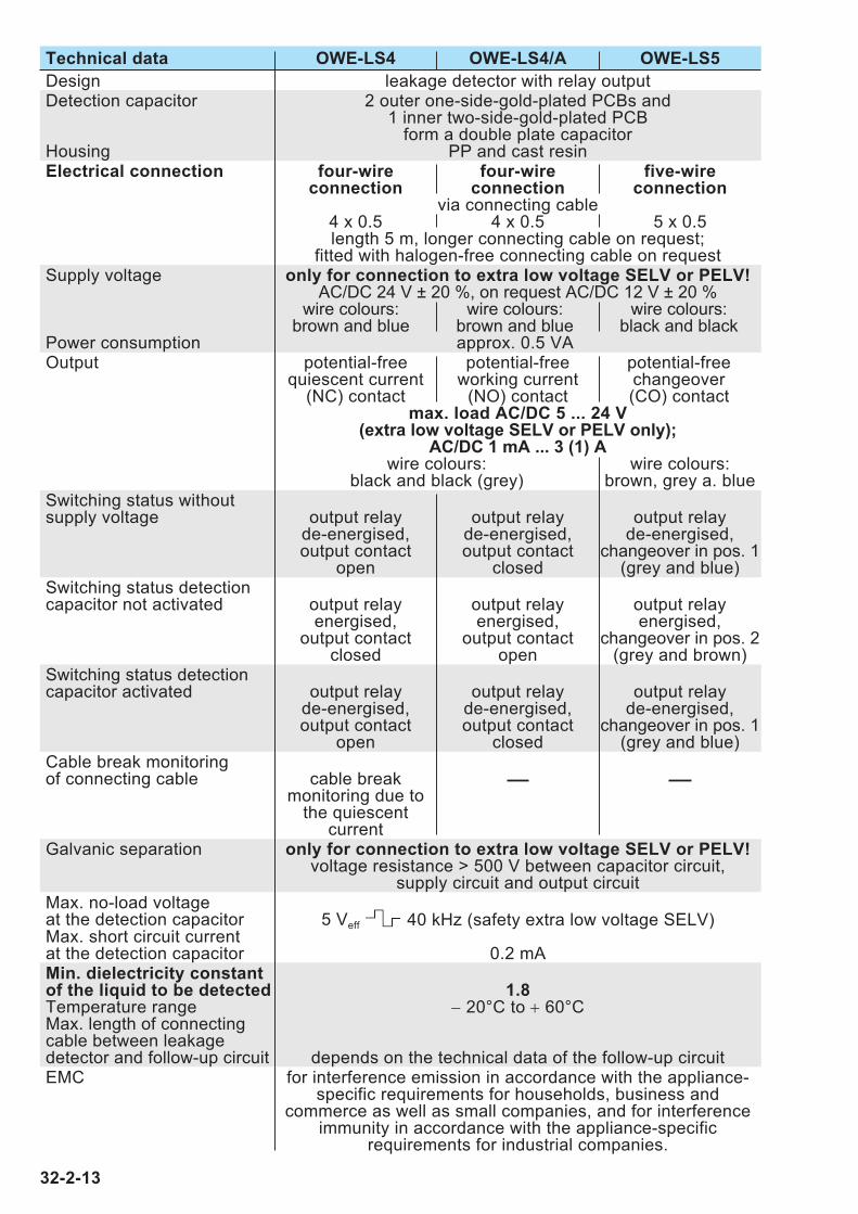
Technical data OWE-LS4 OWE-LS4/A OWE-LS5
Design leakage detector with relay outputDetection capacitor 2 outer one-side-gold-plated PCBs and
1 inner two-side-gold-plated PCB form a double plate capacitor
Housing PP and cast resinElectrical connection four-wire four-wire five-wire
connection connection connectionvia connecting cable
4 x 0.5 4 x 0.5 5 x 0.5length 5 m, longer connecting cable on request;
fitted with halogen-free connecting cable on requestSupply voltage only for connection to extra low voltage SELV or PELV!
AC/DC 24 V ± 20 %, on request AC/DC 12 V ± 20 %wire colours: wire colours: wire colours:
brown and blue brown and blue black and blackPower consumption approx. 0.5 VAOutput potential-free potential-free potential-free
quiescent current working current changeover(NC) contact (NO) contact (CO) contact
max. load AC/DC 5 ... 24 V (extra low voltage SELV or PELV only);
AC/DC 1 mA ... 3 (1) Awire colours: wire colours:
black and black (grey) brown, grey a. blueSwitching status withoutsupply voltage output relay output relay output relay
de-energised, de-energised, de-energised,output contact output contact changeover in pos. 1
open closed (grey and blue)Switching status detection capacitor not activated output relay output relay output relay
energised, energised, energised,output contact output contact changeover in pos. 2
closed open (grey and brown)Switching status detection capacitor activated output relay output relay output relay
de-energised, de-energised, de-energised,output contact output contact changeover in pos. 1
open closed (grey and blue)Cable break monitoringof connecting cable cable break
monitoring due tothe quiescent
currentGalvanic separation only for connection to extra low voltage SELV or PELV!
voltage resistance > 500 V between capacitor circuit,supply circuit and output circuit
Max. no-load voltage at the detection capacitor 5 Veff 40 kHz (safety extra low voltage SELV)Max. short circuit current at the detection capacitor 0.2 mAMin. dielectricity constant of the liquid to be detected 1.8Temperature range − 20°C to + 60°CMax. length of connectingcable between leakagedetector and follow-up circuit depends on the technical data of the follow-up circuitEMC for interference emission in accordance with the appliance-
specific requirements for households, business and commerce as well as small companies, and for interference
immunity in accordance with the appliance-specific requirements for industrial companies.
32-2-13
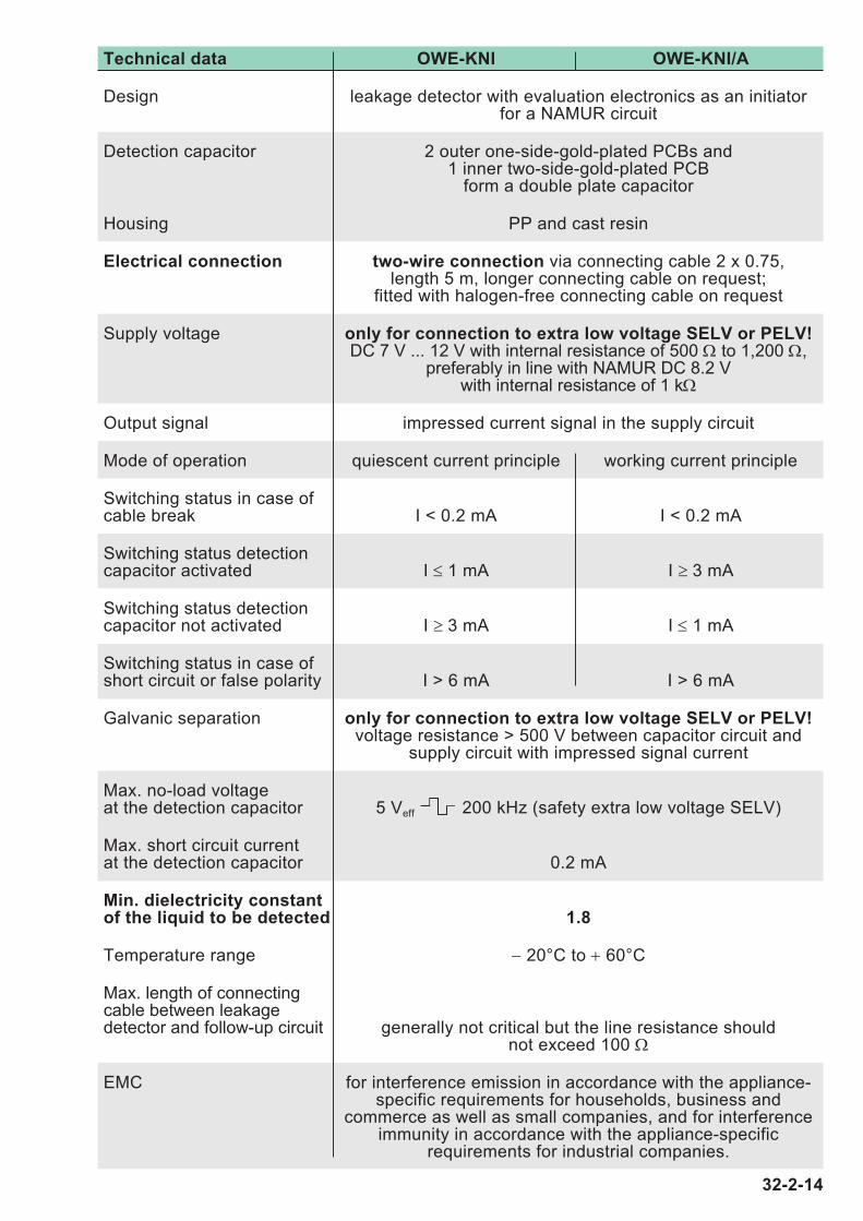
Technical data OWE-KNI OWE-KNI/A
Design leakage detector with evaluation electronics as an initiatorfor a NAMUR circuit
Detection capacitor 2 outer one-side-gold-plated PCBs and1 inner two-side-gold-plated PCB
form a double plate capacitor
Housing PP and cast resin
Electrical connection two-wire connection via connecting cable 2 x 0.75,length 5 m, longer connecting cable on request;
fitted with halogen-free connecting cable on request
Supply voltage only for connection to extra low voltage SELV or PELV!DC 7 V ... 12 V with internal resistance of 500 Ω to 1,200 Ω,
preferably in line with NAMUR DC 8.2 Vwith internal resistance of 1 kΩ
Output signal impressed current signal in the supply circuit
Mode of operation quiescent current principle working current principle
Switching status in case ofcable break I < 0.2 mA I < 0.2 mA
Switching status detection capacitor activated I ≤ 1 mA I ≥ 3 mA
Switching status detection capacitor not activated I ≥ 3 mA I ≤ 1 mA
Switching status in case ofshort circuit or false polarity I > 6 mA I > 6 mA
Galvanic separation only for connection to extra low voltage SELV or PELV!voltage resistance > 500 V between capacitor circuit and
supply circuit with impressed signal current
Max. no-load voltage at the detection capacitor 5 Veff 200 kHz (safety extra low voltage SELV)
Max. short circuit current at the detection capacitor 0.2 mA
Min. dielectricity constant of the liquid to be detected 1.8
Temperature range − 20°C to + 60°C
Max. length of connectingcable between leakagedetector and follow-up circuit generally not critical but the line resistance should
not exceed 100 Ω
EMC for interference emission in accordance with the appliance-specific requirements for households, business and
commerce as well as small companies, and for interference immunity in accordance with the appliance-specific
requirements for industrial companies.
32-2-14
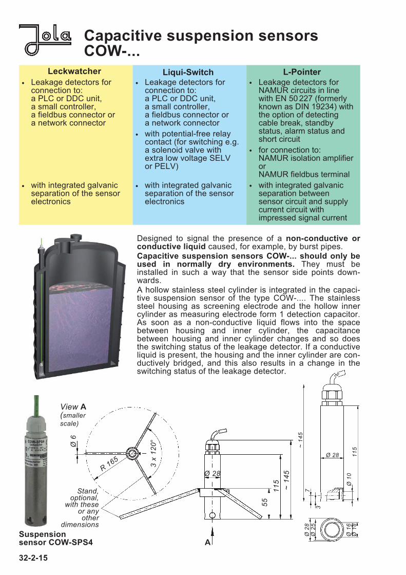
Designed to signal the presence of a non-conductive or conductive liquid caused, for example, by burst pipes. Capacitive suspension sensors COW-... should only beused in normally dry environments. They must be installed in such a way that the sensor side points down-wards.A hollow stainless steel cylinder is integrated in the capaci-tive suspension sensor of the type COW-.... The stainlesssteel housing as screening electrode and the hollow innercylinder as measuring electrode form 1 detection capacitor.As soon as a non-conductive liquid flows into the space between housing and inner cylinder, the capacitance between housing and inner cylinder changes and so doesthe switching status of the leakage detector. If a conductiveliquid is present, the housing and the inner cylinder are con-ductively bridged, and this also results in a change in theswitching status of the leakage detector.
Capacitive suspension sensorsCOW-...
32-2-15
Suspension sensor COW-SPS4
View A(smallerscale)
Stand, optional,
with theseor anyother
dimensions
115
55
Ø 28
A
R 165
3 x
120°Ø
6
~ 14
5
3
7
Ø 1
0
Ø 28
~ 14
5Ø
28
Ø 2
5
Ø 1
6Ø
18
115
Leckwatcher
• Leakage detectors forconnection to: a PLC or DDC unit,a small controller,a fieldbus connector ora network connector
• with integrated galvanicseparation of the sensorelectronics
Liqui-Switch
• Leakage detectors forconnection to: a PLC or DDC unit,a small controller,a fieldbus connector ora network connector
• with potential-free relaycontact (for switching e.g.a solenoid valve withextra low voltage SELVor PELV)
• with integrated galvanicseparation of the sensorelectronics
L-Pointer
• Leakage detectors forNAMUR circuits in linewith EN 50 227 (formerlyknown as DIN 19234) withthe option of detectingcable break, standbystatus, alarm status andshort circuit
• for connection to: NAMUR isolation amplifierorNAMUR fieldbus terminal
• with integrated galvanicseparation between sensor circuit and supplycurrent circuit with impressed signal current

Technical data COW-SPS2 COW-SPS3 COW-SPS4
Design leakage detector with quiescent current / NC (break) contact
Detection capacitor stainless steel housing as screening electrode and inner cylinder as measuring electrode form 1 detection capacitor
Housing stainless steel 316 Ti with PTFE insulator
Electrical connection two-wire connection three-wire connection four-wire connectionvia connecting cable via connecting cable via connecting cable
2 x 0.75 3 x 0.75 4 x 0.5
length 5 m, longer connecting cable on request;fitted with halogen-free connecting cable on request
Supply voltage only for connection to extra low voltage SELV or PELV!
DC 24 V ± 20 % AC/DC 12 ... 30 V; AC/DC 12 ... 30 V;via input resistance wire colours: wire colours:
2 kΩ ... 7.5 kΩ brown and blue brown and blue
Power consumption max. 0.5 W max. 0.5 VA max. 0.5 VA
Output evaluation based on PNP transistor output; potential-free reedthe magnitude of to be wired via contact with protective
power consumption the input resistance of resistance 62 Ω,the follow-up circuit of max. load
2 kΩ ... 7.5 kΩ; AC/DC 30 V, 100 mA,wire colour: black 3 W; wire colours:
black and black
Short circuit protection present, at transistor output, reed contact atIk < 30 mA Ik < 30 mA output short circuit
proof for short periodsvia integrated protective
resistance of 62 Ω;however,
the reed contactis open if the supply
voltage of the sensor isincorrectly connected
Switching status withoutsupply voltage Low signal Low signal reed contact open
Switching status detection capacitor not activated power consumption PNP transistor output reed contact closed
> 2 mA, carries rectifiedgenerates High signal supply voltageat input resistance of = High signal
follow-up circuit
Switching status detection capacitor activated power consumption PNP transistor output reed contact open
< 0.7 mA, carries no voltagegenerates Low signal = Low signalat input resistance of
follow-up circuit
Cable break monitoringof connecting cable cable break monitoring due to the quiescent current
Galvanic separation only for connection to extra low voltage SELV or PELV!voltage resistance > 500 V between capacitor circuit and
supply circuit supply circuit supply circuitand transistor output and output circuit
Max. no-load voltage at the detection capacitor 5 Veff 40 kHz (safety extra low voltage SELV)
Max. short circuit current at the detection capacitor 0.2 mA
Min. dielectricity constant of the liquid to be detected 1.8
Temperature range − 20°C to + 60°C
Max. length of connectingcable between leakagedetector and follow-up circuit depends on the technical data of the follow-up circuit
EMC for interference emission in accordance with the appliance-specificrequirements for households, business and commerce as well as
small companies, and for interference immunity in accordance with the appliance-specific requirements for industrial companies.
32-2-16

Technical data COW-LS4 COW-LS4/A COW-LS5
Design leakage detector with relay outputDetection capacitor stainless steel housing as screening electrode and
inner cylinder as measuring electrodeform 1 detection capacitor
Housing stainless steel 316 Ti with PTFE insulatorElectrical connection four-wire four-wire five-wire
connection connection connectionvia connecting cable
4 x 0.5 4 x 0.5 5 x 0.5length 5 m, longer connecting cable on request;
fitted with halogen-free connecting cable on requestSupply voltage only for connection to extra low voltage SELV or PELV!
AC/DC 24 V ± 20 %, on request AC/DC 12 V ± 20 %wire colours: wire colours: wire colours:
brown and blue brown and blue black and blackPower consumption approx. 0.5 VAOutput potential-free potential-free potential-free
quiescent current working current changeover(NC) contact (NO) contact (CO) contact
max. load AC/DC 5 ... 24 V (extra low voltage SELV or PELV only);
AC/DC 1 mA ... 3 (1) Awire colours: wire colours:
black and black (grey) brown, grey a. blueSwitching status withoutsupply voltage output relay output relay output relay
de-energised, de-energised, de-energised,output contact output contact changeover in pos. 1
open closed (grey and blue)Switching status detectioncapacitor not activated output relay output relay output relay
energised, energised, energised,output contact output contact changeover in pos. 2
closed open (grey and brown)Switching status detectioncapacitor activated output relay output relay output relay
de-energised, de-energised, de-energised,output contact output contact changeover in pos. 1
open closed (grey and blue)Cable break monitoringof connecting cable cable break
monitoring due tothe quiescent
currentGalvanic separation only for connection to extra low voltage SELV or PELV!
voltage resistance > 500 V between capacitor circuit,supply circuit and output circuit
Max. no-load voltage at the detection capacitor 5 Veff 40 kHz (safety extra low voltage SELV)Max. short circuit current at the detection capacitor 0.2 mAMin. dielectricity constant of the liquid to be detected 1.8Temperature range − 20°C to + 60°CMax. length of connectingcable between leakagedetector and follow-up circuit depends on the technical data of the follow-up circuitEMC for interference emission in accordance with the appliance-
specific requirements for households, business and commerce as well as small companies, and for interference
immunity in accordance with the appliance-specific requirements for industrial companies.
32-2-17
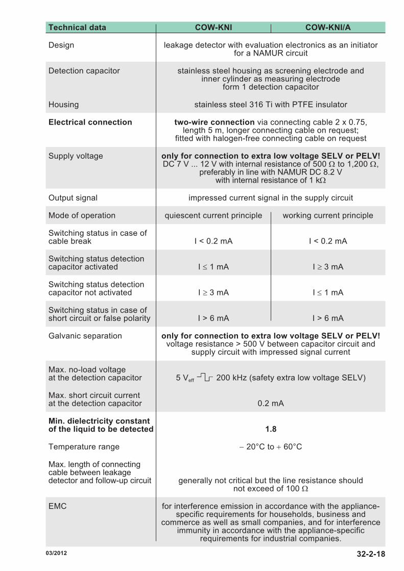
Technical data COW-KNI COW-KNI/A
Design leakage detector with evaluation electronics as an initiatorfor a NAMUR circuit
Detection capacitor stainless steel housing as screening electrode and inner cylinder as measuring electrode
form 1 detection capacitor
Housing stainless steel 316 Ti with PTFE insulator
Electrical connection two-wire connection via connecting cable 2 x 0.75,length 5 m, longer connecting cable on request;
fitted with halogen-free connecting cable on request
Supply voltage only for connection to extra low voltage SELV or PELV!DC 7 V ... 12 V with internal resistance of 500 Ω to 1,200 Ω,
preferably in line with NAMUR DC 8.2 V with internal resistance of 1 kΩ
Output signal impressed current signal in the supply circuit
Mode of operation quiescent current principle working current principle
Switching status in case ofcable break I < 0.2 mA I < 0.2 mA
Switching status detectioncapacitor activated I ≤ 1 mA I ≥ 3 mA
Switching status detectioncapacitor not activated I ≥ 3 mA I ≤ 1 mA
Switching status in case ofshort circuit or false polarity I > 6 mA I > 6 mA
Galvanic separation only for connection to extra low voltage SELV or PELV!voltage resistance > 500 V between capacitor circuit and
supply circuit with impressed signal current
Max. no-load voltage at the detection capacitor 5 Veff 200 kHz (safety extra low voltage SELV)
Max. short circuit current at the detection capacitor 0.2 mA
Min. dielectricity constant of the liquid to be detected 1.8
Temperature range − 20°C to + 60°C
Max. length of connectingcable between leakagedetector and follow-up circuit generally not critical but the line resistance should
not exceed of 100 Ω
EMC for interference emission in accordance with the appliance-specific requirements for households, business and
commerce as well as small companies, and for interference immunity in accordance with the appliance-specific
requirements for industrial companies.
32-2-1803/2012