capacitance
TRANSCRIPT
BA TARGET IIT JEE 2007
XII (ALL)
C O H T E N T S KEYCONCEPTS
EXERCISE-1 EXERCISE-II EXERCISE-III ANSWER KEY

KEY CONCEPTS
1. CAPACITANCE O F A N ISOLATED SPHERICAL CONDUCTOR :
C = 471 e 0 e ( R in a medium C = 47C G „ R in air
3 .
4 .
This sphere is at infinite distance from all the conductors. The Capacitance C = 47T EQR exists between the surface of the sphere & earth .
SPHERICAL CAPACITOR :
It consists of two concentric spherical shells as shown in figure. Here capacitance of region between the two shells is C t and that outside the shell is C 2. We have
471 e n ab C = b - a and C 2 = 471 e Q b
Depending on connection, it may have different combinations of C, and -C2.
PARALLEL PLATE CAPACITOR :
( i ) UNIFORM DI-ELECTRIC MEDIUM :
If two parallel plates each of area A & separated by a distance d are charged with equal & opposite charge Q, then the system is called a parallel plate capacitor & its capacitance is given by,
^ S)6 rA . C = — ; — in a medium C = with air as medium U
This result is only valid when the electric field between plates of capacitor is constant,
( i i ) M E D I U M PARTLY A I R : C = So A d - l t - i
When a di-electric slab of thickness t & relative permittivity e r is introduced between the plates of an air capacitor, then the distance between the plates is effectively reduced by the di-electric slab .
( i i i ) COMPOSITE M E D I U M :
V ^rJ
c =
irrespective of the position of
l l l l P 3 BSSSSii® P 3 BSSSSii®
G 0A I I
- r l r2 r3
CYLINDRICAL CAPACITOR :
It consist of two co-axial cylinders of radii a& b, the outer conductor is earthed. The di-electric constant of the medium filled in the space between the cylinder is
2nene Farad e r . The capacitance per unit length is C = y - r
in m
(fe^Bansal Classes CAPACITANCE 121
CONCEPT o r VARIATION OF PARAMETERS:
6.
9.
10
As capacitance of a parallel plate capacitor isC = e 0 kA , if either of k, A or d varies in the region between the plates, we choose a small dc in between the plates and for total capacitance of system. If all dC's are in series 1 dx -, If all dC's are in parallel C T = } dC
J e 0 k(x)A(x) COMBINATION O F CAPACITORS :
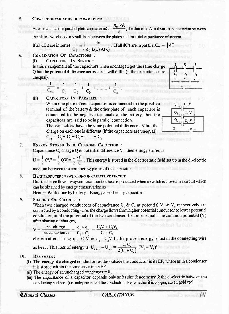
( i ) CAPACITORS IN SERIES :
In this arrangement all the capacitors when uncharged get the same charge Q but the potential difference across each will differ (if the capacitance are unequal).
Q Q Q rIMHh C | C2 C3 v, v, v,
1 1 1 — + — 1 + — + C3 + 1
(ii) CAPACITORS IN PARALLEL :
When one plate of each capacitor is connected to the positive terminal of the battery & the other plate of each capacitor is connected to the negative terminals of the battery, then the capacitors are said to be in parallel connection. The capacitors have the same potential difference, V but the charge on each one is different (if the capacitors are unequal).
% Cj.V
s 1 c,,v
% 1 jC3,y 1 Q +v
eq. C I + C 2 + C 3 + + c ENERGY STORED IN A CHARGED CAPACITOR :
Capacitance C, charge Q & potential difference V; then energy stored is 1 1 1 Q 2 U = - CV 2 = — QV = - — . This energy is stored in the electrostatic field set up in the di-electric
medium between the conducting plates of the capacitor . HEAT PRODUCED IN SWITCHING IN CAPACITIVE CIRCUIT
Due to charge flow always some amount of heat is produced when a switch is closed in a circuit which can be obtained by energy conservation as -Heat = Work done by battery - Energy absorbed by capacitor. SHARING O F CHARGES :
When two charged conductors of capacitance C s & C 2 at potential V } & V 2 respectively are connected by a conducting wire, the charge flows from higher potential conductor to lower potential conductor, until the potential of the two condensers becomes equal. The common potential (V) after sharing of charges;
net charge _ q j + q 2
C, + C 2 V = C,V 1 + C 2 V 2
( V , - V 2 ) 2
net capacitance C, + C 2 C t + C 2
charges after sharing qj = C,'V & q 2 = C2V. In this process energy is lost in the connecting wire C C
as heat. This loss of energy is U i n i t i a l - U e a l = ^ r ^ g REMEMBER :
(i) The energy of a charged conductor resides outside the conductor in its EF, where as in a condenser it is stored within the condenser in its EF.
(ii) The energy of an uncharged condenser = 0 . (iii) The capacitance of a capacitor depends only on its size & geometry & the di-electric between the
conducting surface .(i.e. independent of the conductor, like, whether it is copper, silver, gold etc) <§Bansal Classes CAPACITANCE

EXERCISE # I Q.i
Q.2
Q.3
Q.4
Q.5
Q.6
.CO,
A solid conducting sphere of radius 10 cm is enclosed by a thin metallic shell of radius 20 cm. A charge q = 20pC is given to the inner sphere. Find the heat generated in the process, the inner sphere is connected to the shell by a conducting wire The capacitor each having capacitance C = 2pF are connected with a battery of emf 30 V as shown in figure. When the switch S is closed. Find (a) the amount of charge flown through the battery (b) the heat generated in the circuit (c) the energy supplied by the battery (d) the amount of charge flown through the switch S The plates of a parallel plate capacitor are given charges +4Q and -2Q. The capacitor is then connected across an uncharged capacitor of same capacitance as first one (= C). Find the final potential difference between the plates of the first capacitor. +i, -In the given network if potential difference between p and q is 2V and C 2 = 3 C r Then find the potential difference between a&b.
' 3 0 V
H Mq C, C.
Find the equivalent capacitance of the circuit between point A and B.
c 2C 11
4C 11
8C 11 11
- C :
11
11
: C :
11
! 1
11
\ \ \ \ \
r c y-Infinite / section/
c 11
2C 11
4C II 8C
+ 3 q + q
The two identical parallel plates are given charges as shown in figure. If the plate area of either face of each plate is A and separation between plates is d, then find the amount of heat liberate after closing the switch.
Q. 7 Find heat produced in the circuit shown in figure on closing the switch S.
Q.8 In the following circuit, the resultant capacitance between A and B is 1 pF. Find the value of C.
T T 2 ^ f
Q.9 Three capacitors of 2pF, 3pF and 5|iF are independently charged with batteries of emf's 5V, 20V and 10V respectively. After disconnecting from the voltage sources. These capacitors are connected as shown in figure with their positive polarity plates are connected to A and negative polarity is earthed. Now a battery of 20V and an uncharged capacitor of 4jaF capacitance are connected to the junction A as shown with a switch S. When switch is closed, find :
(a) the potential of the junction A. (b) final charges on all four capacitors.
2\xV
^Slr
5NF \ I'— —II—I 20V 4|j.F 4r
(fe^Bansal Classes CAPACITANCE 121

Q.10 Find the charge on the capacitor C = 1 pF in the circuit shown in the figure. 7 Iph IjxK IpF IpF C-luF l(iF :pnF yUlF: :IMF :
Q.ll Find the capacitance of the system shown in figure. k = 1 k = 2 k = 3 k = 4
Q.12 The figure shows a circuit consisting of four capacitors. Find the effective capacitance between X and Y.
Q. 13 Five identical capacitor plates, each of area A, are arranged such that adjacent plates are at a distance'd* apart, the plates are connected to a source of emf V as shown in figure. The charge on plate 1 is and that on plate 4 is . V- +
Q.14 In the circuit shown in the figure, intially SW is open. When the switch is closed, the charge passing through the switch in the direction
to
X AE-I
60 V 2 nF 60 V SW 3
1 J
Q.15
Q.16
In the circuit shown in figure, find the amount of heat generated when switch s is closed.
Two parallel plate capacitors of capacitance C and 2C are connected in parallel then following steps are performed. (i) Abattery of voltage V is connected across points A and B. (ii) A dielectric slab of relative permittivity k is slowly inserted in capacitor C. (iii) Battery is disconnected. (iv) Dielectric slab is slowly removed from capacitor. Find the heat produced in (i) and work done by external agent in step (ii) & (iv).
Q.17 The plates of a parallel plate capacitor are separated by a distance d = 1 cm. Two parallel sided dielectric slabs of thickness 0.7 cm and 0.3 cm fill the space between the plates. If the dielectric constants of the two slabs are 3 and 5 respectively and a potential difference of440V is applied across the plates. Find:
(i) the electric field intensities in each of the slab s. (ii) the ratio of electric energies stored in the first to that in the second dielectric slab. Q.18 A 10 pF and 20 pF capacitor are connected to a 10 V cell in parallel for some time after which the
capacitors are disconnected from the cell and reconnected at t = 0 with each other, in series, through wires of finite resistance. The +ve plate of the first capacitor is connected to the -ve plate of the second capacitor. Draw the graph which best describes the charge on the +ve plate of the 20 pF capacitor with increasing time.
List of recommended questions from LE. Irodov. 3.101, 3.102, 3.103, 3.113, 3.117, 3.121, 3.122, 3.123,3.124, 3.132,3.133, 3.141,3.142, 3.177,3.184,
3.188. 3.199. 3.200,3.201. 3.203, 3.204. 3.205 (fe^Bansal Classes CAPACITANCE 121

EXERCISE # II Q. 1 (a) For the given circuit. Find the potential difference across all the capacitors,
(b) How should 5 capacitors, each of capacities, lpF be connected so as to produce a total capacitance of 3/7 pF.
6oF, Ih-H^f
—'—I h 9|iF 8(xF
+. -25V
Q.2 The gap between the plates of a plane capacitor is filled with an isotropic insulator whose di-electric 71 constant varies in the direction perpendicular to the plates according to the law K = K j 1 + sin — X L d
where d is the separation, between the plates & K t is a constant. The area of the plates is S. Determine the capacitance of the capacitor.
Q.3 Five identical conducting plates 1,2,3,4 & 5 are fixed parallel 5
to and equdistant from each other (see figure). Plates 2 & 5 are connected by a conductor while 1 & 3 are joined by another conductor. The junction of 1 & 3 and the plate 4 are connected to a source of constant e.m.f. V 0 . Find;
(i) the effective capacity of the system between the terminals of the source. (ii) the charges on plates 3 & 5.
Given d = distance between any 2 successive plates & A= area of either face of each plate .
Q.4 Apotential difference of300 Vis applied between the plates of a plane capacitor spaced 1 cm apart. A plane parallel glass plate with a thickness of 0.5 cm and a plane parallel paraffin plate with a thickness of 0.5 cm are placed in the space between the capacitor plates find :
(j) Intensity of electric field in each layer. (ii) The drop of potential in each layer. (iii) The surface charge density of the charge on capacitor the plates. Given that: k g l a s s = 6, k p a r a f f i n = 2
Q.5 A charge 200pC is imparted to each of the two identical parallel plate capacitors connected in parallel. At t =0, the plates of both the capacitors are 0.1 m apart. The plates of first capacitor move towards each other with relative velocity 0.001 m/s and plates of second capacitor move apart with the same velocity. Find the current in the circuit at the moment.
Q.6 A parallel plate capacitor has plates with area A & separation d . A battery charges the plates to a potential difference of V 0 . The battery is then disconnected & a di-electric slab of constant K& thickness d is introduced. Calculate the positive work done by the system (capacitor + slab) on the man who introduces the slab.
Q.7 A capacitor of capacitance C 0 is charged to a potential V 0 and then isolated. A small capacitor C is then charged from C 0, discharged & charged again, the process being repeated n times. The potential of the large capacitor has now fallen to V. Find the capacitance of the small capacitor. If V 0 = 100 volt, V=35volt, find the value ofn for C 0 = 0.2 pF & C = 0.01075 pF . Is it possible to remove charge on C 0 this way?
Q. 8 When the switch S in the figure is thrown to the left, the plates of capacitors . V C, acquire a potential difference V. Initially the capacitors C 2 C 3 are uncharged. Thw switchis now thrown to the right. What are the final charges q p q 2 & q 3 on the corresponding capacitors.
TLPI I c T
(fe^Bansal Classes CAPACITANCE 121
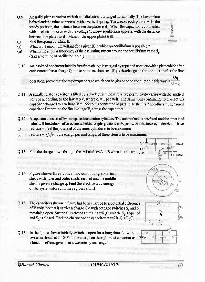
Q.9 A parallel plate capacitor with air as a dielectric is arranged horizontally. The lower plate is fixed and the other connected with a vertical spring. The area of each plate is A. In the steady position, the distance between the plates is d 0. When the capacitor is connected with an electric source with the voltage V, a new equilibrium appears, with the distance between the plates as d r Mass of the upper plates is m.
(1) Find the spring constant K. (ii) What is the maximum voltage for a given K in which an equilibrium is possible ? (lii) What is the angular frequency of the oscillating system around the equilibrium value dj.
(take amplitude of oscillation « d {)
Q.10 An insolated conductor initially free from charge is charged by repeated contacts with a plate which after each contact has a charge Q due to some mechanism. If q is the charge on the conductor after the first
operation, prove that the maximum charge which can be given to the conductor in this way is ~ Qq
Q.ll A parallel plate capacitor is filled by a di-electric whose relative permittivity varies with the applied voltage according to the law = aV, where a = 1 per volt. The same (but containing no di-electric) capacitor charged to a voltage V = 156 volt is connected in parallel to the first "non-linear" uncharged capacitor. Determine the final voltage V f across the capacitors.
Q.12 A capacitor consists of two air spaced concentric cylinders. The outer of radius b is fixed, and the inner is of radius a If breakdown of air occurs at field strengths greater than E , show that the inner cylinder should have
(i) radius a = b/e if the potential of the inner cylinder is to be maximum (ii) radius a = b/Ve if the energy per unit length of the system is to be maximum.
,.JT 5 V - r -Q. 13 Find the charge flown through the switch from Ato B when it is closed. 6 m F Jr~
Q.15
4=6nF
5V :d=6nf
Q.14 Figure shows three concentric conducting spherical shells with inner and outer shells earthed and the middle shell is given a charge q. Find the electrostatic energy of the system stored in the region I and II.
The capacitors shown in figure has been charged to a potential difference of V volts, so that it carries a charge CV with both the switches Sj and S 2
remaining open. Switch Sj is closed at t=0. At t=R,C switch Sj is opened and S 2 is closed. Find the charge on the capacitor at t=2RjC + R^C.
Hi s, s,
Q.16 In the figure shown initially switch is open for a long time. Now the switch is closed at t = 0. Find the charge on the rightmost capacitor as "yv a function of time given that it was intially unchanged.
(fe^Bansal Classes CAPACITANCE 121

Q.17 In the given circuit, the switch is closed in the position 1 at t = 0 and then moved , I V to 2 after 250 p,s. Derive an expression for current as a function of time for J^ov [ 2
t > 0. Also plot the variation of current with time. I X 40V
Q.18 Find the charge which flows from point Ato B, when switch is closed.
EXERCISE # III
VL 5(IF 5NF 5^F 5(.IF 5(IF
120V
:500FJ
:0.5 NF
A B
10V
Q. 1 Two parallel plate capacitors A&B have the same separation d=8.85 x lO^m between the plates. The plate areas of A & B are 0.04 m 2 & 0.02 m 2
respectively. A slab of di-electric constant (relative permittivity) K=9 has dimensions such that it can exacdy fill the space between the plates of capacitor B.
(i) the di-electric slab is placed inside A as shown in the figure (i) Ais then charged to a potential difference of 110 volt. Calculate the capacitance of A and the energy stored in it.
(ii) the battery is disconnected & then the di-electric slab is removed from A. Find the work done by the external agency in removing the slab from A.
(iii) the same di-electric slab is now placed inside B, filling it completely. The two capacitors A& B are then connected as shown in figure (iii). Calculate the energy stored in the system. [ JEE '93,7]
Q.2
Q.3
Q.4
Q.5
©
Two square metallic plates of 1 m side are kept 0.01 m apart, like a parallel plate capacitor, in air in such a way that one of their edges is perpendicular, to an oil surface in a tank filled with an insulating oil. The plates are connected to a battery of e.m.f. 500 volt. The plates are then lowered vertically into the oil at a speed of 0.001 m/s. Calculate the current drawn from the battery during the process, [di-electric constant of oil = 11, e 0 = 8.85 x 10" 1 2 C 2 /N 2 m 2 ] [ JEE '94, 6 ] A parallel plate capacitor C is connected to a battery & is charged to a potential difference V. Another capacitor of capacitance 2C is similarly charged to a potential difference 2V volt. The charging batteiy is now disconnected & the capacitors are connected in parallel to each other in such a way that the positive terminal of one is connected to the negative terminal of other. The final energy of the configuration is: (A) zero (B) - CV 2
25 (C) — CV2 (D) - CV 2 [JEE'95, 1 ]
The capacitance of a parallel plate capacitor with plate area 'A' & separation d is C. The space between the plates is filled with two wedges of di-electric constant Kj & K 2 respectively. Find the capacitance of the resulting capacitor.
[JEE'96, 2 ]
IOOV
2nF 1 - .
Two capacitors A and B with capacities 3 pF and 2 pF are charged to a potential difference of 100 V and 180 V respectively. The plates of the capacitors are connected as shown in figure with one wire from each capacitor free. The upper plate of a is positive and that of B is negative, an uncharged 2 pF capacitor C with lead wires falls on the free ends to complete the circuit. Calculate: the final charges on the three capacitors The amount of electrostatic energy stored in the system before and after the completion of the circuit.
[JEE'97 (cancelled)]
B 180V
(fe^Bansal Classes CAPACITANCE 121

Q.6 An electron enters the region between the plates of a parallel plate capacitor at a point equidistant from eitherplate. The capacitor plates are 2* 10 _ 2mapart& 10 - 1 m long. A potential difference of300 volt is kept across the plates. Assuming that the initial velocity of the electron is parallel to the capacitor plates, calculate the largest value ofthe velocity of the electron so that they do not fly out of the capacitor at the other end. [ JEE '97, 5 ]
Q. 7 For the circuit shown, which of the following statements is true ? (A) with S, closed, Vj = 15 V, V 2 = 20 V (B) with S 3 closed, Vj = V 2 = 25 V (C) with & S 2 closed, Vj = V 2 = 0 (D) with Sj & S 2 closed, V l = 30 V, V 2 = 20 V
V, =30V
[JEE'99, 2 ]
Q.8 Calculate the capacitance of a parallel plate condenser, with plate area A and distance between plates d, when filled with a medium whose permittivity varies as;
e (x)= e 0 + P x S ( X ) = G 0 + P ( d - x )
0 < x < | 4 < x < d . [REE2000, 6]
Q. 9 Two identical capacitors, have the same capacitance C. One of them is charged to potential V t and the other to V 2 . The negative ends of the capacitors are connected together. When the positive ends are also connected, the decrease in energy of the combined system is [ JEE 2002 (Scr), 3 ]
(A) Mvf-vl) (B)Mv,2+v22) ( q I c ^ - v J ( D ^ c f a + v J
Q.10 In the given circuit, the switch S is closed at time t = 0. The charge Q on the capacitor at any instant t is given by Q (t) = Q 0 (l-e"0*). Find the value of Q 0 and a in terms of given parameters shown in the circuit.
[JEE 2005]
Q.l l Given: Rj = ID , R2 = 2Q, Cx = 2pF, C 2 = 4pF The time constants (in pS) for the circuits I, n, HI are respectively
.C, !!—i—
hi "C2
k v h-—
R,: K r . - T T-r. , v V '
(II.) (A) 18, 8/9, 4 (C) 4, 8/9, 18
(in) (B) 18, 4, 8/9 (D) 8/9, 18,4
1—m— s/ + c "T v
[JEE 2006]
(fe^Bansal Classes CAPACITANCE 121
ANSWER KEY EXERCISE # I
Q.2 (a) 20 pC, (b) 0.3 mJ, (c) 0.6 mJ. (d) 60 [iC
Q.4 30 V 32 Q.8 - M F
Q.5 C 1 q 2 d Q-6 i Z T
Q.l 9J
Q.3 3Q/2C
Q.7 0 100 Q.9 (a) — volts; (b) 28.56 |iC, 42.84 pC, 71.4 jnC, 22.88 pC Q.10 10 pC
Q.ll 25 e„A 24 d
Q.15 150 mJ
Q.12 ^ F Q.13 A G0 V 2A e 0 V Q.14 60 (ic,AtoB
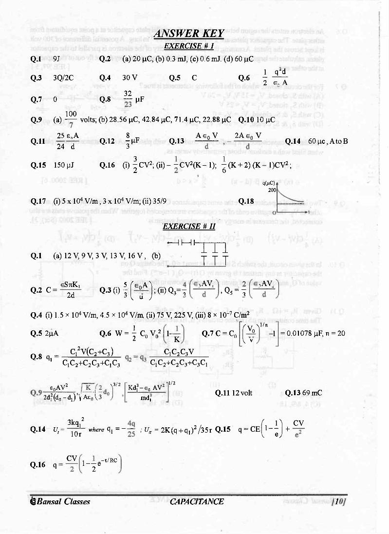
Q.16 (i) | C V 2 ; (ii) - ~ CV2(K- 1); ^ (K + 2) (K - l ^ V 2 ; q(nC),
200 Q. 17 (i) 5 X 10⁴ V/m, 3 x 10⁴ V/m; (ii) 3 5/9 Q.18
EXERCISE # II
H H I Q.l (a) 12 V, 9 V, 3 V, 13 V, 16 V , (b) m
T TT
Q.2 C = GSTIK,
2d Q.3 (i) 3 5 f e 0 A ^ ;(ii)Q3=T
IAV„
,Q5 = t v " y ,AV
Q.4 (i) 1.5 x 10⁴ V/m, 4.5 x 10 4 V/m, (ii) 75 V, 225 V, (iii) 8 x 10"7 C/m 2
Q.5 2[iA Q.6 W = \ C 0 V 0 2 1- K Q.7 C = C n
q.8 q i- Ci2V(C2+C3) CiC 2 +C 2 C 3 +Cj c 3
C 1 C 2 C 3 V
f \ T \ 1 / n vo V V
-1 = 0.01078 |iF,n = 20
c 1 c 2 + c 2 c 3 + c 3 c 1
SpAV2
2d2(d0 -d!)'v As0 ^3 \3 /2 Kdf-e 0 AV2
MDJ
1/2
Q.ll 12 volt Q.13 69 mC
Q.14 U, 3kg, 2
lOr where q, = ~ ; Uu = 2K(q + q i ) 2 / 3 5 r Q.15 q = CE r O CV 1 — v e y
+
Q.16 q CV 1-—e~t/RC 2
(fe^Bansal Classes CAPACITANCE 121

Q.17 For t < 250 ps, I = 0.04 e^° 0 0 t amp ; For t > 250 ps, I = - 0.1 ie-4000(t-250)xi(r6 a m p ;
I(ajnp)
0.04 0.015
4 0 0 ^ Q . 1 8 - — P €
-o.n •t
( x I O ^ s )
EXERCISE # III
Q.l (i) 0.2 x 10"8 F, 1.2 x lO"5 J ; (ii) 4.84 x 10"5 J ; (iii) 1.1 x 10"5 J
Q.2 4.425 x 10~9 Ampere Q . 3 B q.4 C K ^ /n K, (Ka-KO K,
Q . 5 Q A = 9 0 pC, Q B = 1 5 0 pC, Q C = 2 1 0 pC, UJ = 4 7 . 4 MJ, U F = 1 8 M J
V48 Q ' 6 2^9A &
Q.9 C
Q.7 D Q.8 ^ 2 e0
2 s0
CVR, R1+R2 Q . 1 0 Q0 = R i+R2 anda= Q. l l

XII (ALL)
quesjjommm. <M

QUESTION FOR SHORT ANSWER
Q.l
Q.2
Q.3
Q.4
Q.5
Q.6
Q.7
Q8
Q.9
The electric strength of air is about 30,000 V/cm. By this we mean that when the electric field intensity exceeds this value, a spark will jump through the air. We say that "electric breakdown" has occurred. Using this value, estimate the potential difference between two objects where a spark jumps. Atypical situation might be the spark that jumps between your body and a metal door handle after you have walked on a deep carpet or slid across a plastic car seat in very dry weather. If you grasp the two wires leading from the two plates of a charged capacitor, you may feel a shock. The effect is much greater for a 2-pF capacitor than for a 0.02p,F capacitor, even though both are are charged to the same potential difference. Why?
<T(+) Three infinite nonconducting sheets, with uniform surface charge densities a, 2a and 3ct are arranged to be parallel like the two sheets in Fig. What is their order, from left to right, if the electric field E produced by the arrangement has magnitude E = 0 in one region and E = 2a/e 0 in another region? As shown in the figure plots of charge versus potential difference for three parallel plate capacitors, which have the plate areas and separations given in the table. Which of the plots goes with which of the capacitors?
a( - )
Capacitor Area Separation 1 A d 2 2A d 3 A 2d
Initially, a single capacitance C t is wired to a battery. Then capacitance C 2 is added in parallel. Are (a) the potential difference across C1 and (b) the charge qj on C t now more than, less than, or the same as previously? (c) Is the equivalent capacitance C 1 2 of Cj and C 2 more than, less than, or equal to Cj? (d) Is the total charge stored on C and C , together more than, less than, or equal to the charge stored previously on Cj? As shown in the figure three circuits, each consisting of a switch and two capacitors, initially charged as indicated. After the switches have been closed, in which 6q_ circuit (if any) will the charge on the left-hand capacitor 2C (a) increase, (b) decrease and (c) remain the same?
6q_
2C
_ Jq 6q__ C 3C 2C
Cap-monster maze. Inthe Figure all the capacitors have a capacitance = = -- I I of 6.0 pF, and all the b atteries have an emf of 10V What is the charge | J_ J ^ hf¥T on capacitor C? (If you can find the proper loop through this maze, you : = T ~ ,, 4 ,, 4 4= T can answer the question with a few seconds of mental calculation.) -r I c 1
I
HH An oil filled capacitor has been designed to have a capacitance C and to operate safely at or below a certain maximum potential difference V m without arcing over. However, the designer did not do a good job and the capacitor occasionally arcs over. What can be done to redesign the capacitor, keeping C and V m unchanged and using the same dielectric? One of the plates of a capacitor connected to battery is earthed. Will the potential diffrence between the plates change if the earthing wire is removed?
(fe Bansal Classes Question Bank on Capacitance [13]

ONLY ONE OPTION IS CORRECT. Take approx. 2 minutes for answering each question.
Q. 1 The distance between plates of a parallel plate capacitor is 5d. Let the positively charged plate is at x=0 and negatively charged plate is at
1 * x=5d. Two slabs one of conductor and other of a dielectric of equal thickness d are inserted between the plates as shown in figure. Potential versus distance graph will look like:
v w v
A) ( B ) ( C )
Cond. Diele.
x=0 x=d x=2d x=3d x=4d x=5d
VI
(D)
Q.2 A parallel plate capacitor has two layers of dielectric as shown in figure. This capacitor is connected across a battery. The graph which shows the variation of electric field (E) and distance (x) from left plate.
y y y
( A ) ( B ) ( C )
(d,0) (3d,0) " (d,0) (3d,0) " (d,0) (3d,0)~
k=2 k=4
(d,0) (3d,0)
( D )
(d,0) (3d,0)
Q . 3
Q . 4
L
The distance between the plates of a charged parallel plate capacitor is 5 cm and electric field inside the plates is 200 Vcnr 1 . An uncharged metal bar of width 2 cm is fully immersed into the capacitor. The length of the metal bar is same as that of plate of capacitor. The voltage across capacitor after the immersion of the bar is (A) zero (B)400V (C)600V (D)100V
Three large plates are arranged as shown. How much charge will flow through the key k if it is closed?
( A ) 5Q 4Q
( B ) F ( C ) 3 Q (D) none
2Q 2d
1
Q.5
u
Q.6 - >
Q . 7
u
Five conducting parallel plates having area Aand separation between them d, are placed as shown in the figure. Plate number 2 and 4 are connected wire and between point A and B, a cell of emfE is connected. The charge flown through the cell is
( A ) 3 e 0 AE 4 d ( B )
2 s 0 AE 3 d ( C )
4s 0 AE ( D )
e 0 AE 2d
E
If charge on left plane of the 5 pF capacitor in the circuit segment shown 5
in the figure is -20pC, the charge on the right plate of 3 pF capacitor is (A) +8.57 pC (B) -8.57 pC (C)+11.42pC (D)-11.42pC Five identical capacitor plates are arranged such that they make capacitors each of 2 pF. The plates are connected to a source of emf 10 V. The charge on plate C is (A) + 20 pC (B) + 40 pC (C) + 60 pC (D) + 80pC
w |3nF
2(iF | f f H
UjiF
(fe Bansal Classes Question Bank on Capacitance [13]

Q.8
L
A capacitor of capacitance C is charged to a potential difference V from a cell and then disconnected from it. Acharge +Q is now given to its positive plate. The potential difference across the capacitor is now (A) V (B) V + Q ( C ) v + f (D) V - ^ , if V < CV
Q.9 In the circuit shown in figure charge stored in the capacitor of capacity 5 pf is (A) 60 pC (B) 20 pC (C) 30 pC (D) zero
M^lfP^lf.
100 V
Q.10 A conducting body 1 has some initial charge Q, and its capacitance is C. There are two other conducting bodies, 2 and 3, having capacitances : C 2 = 2C and C 3 -» QO. Bodies 2 and 3 are initially uncharged. "Body 2 is touched with body 1. Then, body 2 is removed from body 1 and touched with body 3, and then removed." This process is repeated N times. Then, the charge on body 1 at the end must be (A) Q / 3 N (B) Q / 3 N _ 1 ( C ) Q / N 3 (D) None
Q.ll Condenser A has a capacity of 15 pF when it is filled with a medium of dielectric constant 15. Another condenser B has a capacity 1 pF with air between the plates. Both are charged separately by a battery
C of 100V. After charging, both are connected in parallel without the battery and the dielectric material being removed. The common potential now is (A) 4 0 0 V (B) 8 0 0 V (C) 1 2 0 0 V (D) 1600V
Q.12 In the adjoining figure, capacitor (1) and (2) have a capacitance C' each. When the dielectric of dielectric consatnt K is inserted between the plates of one of the capacitor, the total charge flowing through battery is
,c t ( A )
KCE K + l from B to C (B) KCE
K + l from C to B ( K - l ) C E
(C) + ^ FROM B t o C ( K - l ) C E A
(D) 2 ( K + 1 ) from C to B
h
Q. 13 Two identical capacitors 1 and 2 are connected in series toabatteryas shown in figure. Capacitor 2 contains a dielectric slab of dielectric constant k as shown. Q t
and Q 2 are the charges stored in the capacitors. Now the dielectric slab is removed and the corresponding charges are Q' j and Q' 2. Then
( A ) q; = k+i Qi k (B) Q2 _ k + l
( C ) Q ^ _ k + 1 Q 2 ~ 2k (D) 01
Qi
H ^ k 2
-WUr 1
Q. 14 The area of the plates of a parallel plate capacitor is A and the gap between them is d. The gap is filled with a non-homogeneous dielectric whose dielectric constant varies with the distance 'y' from one plate
• as : K = ^sec(7ty/2d), where X is a dimensionless constant. The capacitance of this capacitor is (A) 7ie0^ A/2d (B)7rs 0XA/d (C) 27te0k A/d (D)none
Q.15 A capacitor stores 60pC charge when connected across a battery. When the gap between the plates is filled with a dielectric, a charge of 120pC flows through the battery. The dielectric constant of the material inserted is: (A) 1 (B) 2 . (C) 3 (D) none i
(fe Bansal Classes Question Bank on Capacitance [13]
Q.16 £ •
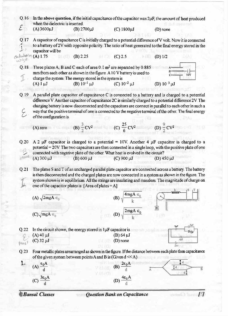
In the above question, if the initial capacitance of the capacitor was 2pF, the amount of heat produced when the dielectric is inserted. (A) 3600pJ (B) 2700pJ (C) 1800pJ (D)none
Q.17 A capacitor of capacitance C is initially charged to a potential difference of V volt. Now it is connected •j to a battery of 2V with opposite polarity. The ratio of heat generated to the final energy stored in the
capacitor will be (A) 1.75 (B) 2.25 (C) 2.5 (D) 1/2
Q.18
Q.19
I
Three plates A B and C each of area 0.1 m 2 are separated by 0.885 mm from each other as shown in the figure. A10 V battery is used to charge the system. The energy stored in the system is ( A ) l p J (B) 10 _ 1 p j (C) 10' 2 pJ
A -B -C-
hH 10V
(D) 10" 3pJ A parallel plate capacitor of capacitance C is connected to a battery and is charged to a potential difference V. Another capacitor of capacitance 2C is similarly charged to a potential difference 2 V. The charging battery is now disconnected and the capacitors are connect in parallel to each other in such a way that the positive terminal of one is connected to the negative terminal of the other. The final energy of the configuration is
(A)zero ( B ) - CV 2 25 „ ( C ) y C V 2 ( D ) - C V 2
Q.20 A 2 pF capacitor is charged to a potential = 10V. Another 4 pF capacitor is charged to a potential = 20V. The two capacitors are then connected in a single loop, with the positive plate of one
; connected with negative plate of the other. What heat is evolvecl in the circuit? (A) 300 p j (B) 600 pJ (C) 900 p j (D)450pJ
Q.21 The plates S and T of an uncharged parallel plate capacitor are connected across a battery. The battery is then disconnected and the charged plates are now connected in a system as shown in the figure. The system shown is in equilibrium. All the strings are insulating and massless. The magnitude of charge on one of the capacitor plates is: [Area of plates=A]
(A) pmgA
(C)VmgA
( B )
(D)
4mgA
2mgA e 0
-^svtvw
777777777777777777
m
ininiii
Q.22 In the circuit shown, the energy stored in 1 pF capacitor is (A) 40 pJ (B) 64 pJ (C) 32 pJ (D)none
3nF
IHF
Q.23 Four metallic plates arearranged as shown in the figure. If the distance between each plate then capacitance of the given system between points A and B is (Given d « A)
I - , _ s n A 2s n A / , I 1 (A)
(C)
S p A
d 3s 0 A
d
( B )
( D )
2s 0 A
4s o A
(fe Bansal Classes Question Bank on Capacitance [13]

Q.24
£ Q.25
cP
What is the equivalent capacitance of the system of capacitors between A & B
.A
W~6c (B) 1.6 C (C)C (D) None 2. B
Q.26 £ .
Q.27
I-
From a supply of identical capacitors rated 8 pF, 250 V, the minimum number of capacitors required to form a composite 16 pF, 1000 Vis : (A) 2 (B) 4 (C) 16 (D) 32
The minimum number of capacitors each of 3 pF required to make a circuit with an equivalent capacitance 2.25 pF is (A) 3 (B)4 (C)5 (D)6
The capacitance (C) for an isolated conducting sphere of radius (a) is given by 47ts0a. If the sphere is enclosed with an earthed concentric sphere. The ratio of the radii of the spheres being n
capacitance of such a sphere will be increased by a factor (n-1) then the
(A)n (B) n
(C) (n -1 ) (D) a . n Q.28
£ Q.29
£
Q.30
y
(n -1 ) - ' n Two capacitor having capacitances 8 pF and 16 pF have breaking voltages 20 V and 80 V. They are combined in series. The maximum charge they can store individually in the combination is (A) 160 pC (B) 200 p,C (C) 1280 p,C (D) none of these
A capacitor of capacitance 1 pF withstands the maximum voltage 6 kV while a capacitor of 2 pF withstands the maximum voltage 4 kV. What maximum voltage will the system of these two capacitor withstands if they are connected in series? (A) lOkV (B)12kV (C) 8 kV (D)9kV
Four identical plates 1,2,3 and 4 are placed parallel to each other at equal distance as shown in the figure. Plates 1 and 4 are joined together and the space between 2 and 3 is filled with a dielectric of dielectric constant k = 2. The capacitance of the system between 1 and 3 & 2 and 4 are Cj and C2
C, respectively. The ratio — is : C-2
(A)-: (B)l 3 ( C ) 5 (D)
Q . 3 1
Q.32 # In the circuit shown in figure, the ratio of charges on 5pF and 4pF capacitor is: (A) 4/5 (B)3/5 (C) 3/8 (D) 1/2 In the circuit shown, a potential difference of 60V is applied across AB. The potential difference between the point M and N is (A) 10 V (B) 15V (C) 20 V (D) 30 V
3jiF •JL— 5(iF
4nF 6V
r - r ^ h r 60V C
Li B I 2 d H
(fe Bansal Classes Question Bank on Capacitance [13]

Q. 3 3 Find the equivalent capacitance across A& B t 28 (A) y pf
(C) 15 pF
23NF 7(iF 15
(B) y p F (D)none
A —'h —1 !3pF IpF B 12pF L—IK —11— lOtlF UiF Q, 3 4 A capacitor of capacitance 1 pF with stands the maximum voltages 6 KV while a capacitor of capacitance
2.0 pF with stands the maximum voltage = 4KV. if the two capacitors are connected in series, then the ~t. two capacitors combined can take up a maximum voltage of
v V (A) 2.4 KV (B) 5 KV (C) 9 KV (D) 10 KV
3C;lkV 2C;2kV —H H
7C;lkV 3C;2kV
Q. 3 5 The diagram shows four capacitors with capacitances and break down voltages as mentioned. What should be the maximum value of the external emf source such that no capacitor breaks down?[Hint: First of all find out the break down voltages of each branch. After that compare them. ] (A)2.5kV (B)10/3kV (C)3kV (D) 1 kV
Q.36 Three capacitors 2 pF, 3 pF and 5 pF can withstand voltages to 3V, 2V and IV respectively. Their series combination can withstand a maximum voltage equal to (A) 5 Volts (B) (31/6) Volts (C) (26/5) Volts (D)None
Q.37 Find equivalent capacitance across AB (all capacitances in pF) 20 (A) y p F
(C) 48 pF (B) 9pF (D) None
B
Q. 3 8 Three long concentric conducting cylindrical shells have radii R, 2R and 2^2 R. Inner and outer shells are connected to each other. The capacitance across middle and inner shells per unit length is:
I
Q.39
(A) /n2 (B) 6 0 In 2 (C) 2/n2 (D) None
A charged capacitor is allowed to discharge through a resistance 2Q by closing the switch S at the instant t = 0. At time t = In 2 ps, the reading of the ammeter falls half of its initial value. The resistance of the ammeter equal to (A) 0 (B)2Q (C)°o (D) 2MQ
Q. 40 A capacitor C = 100 pF is connected to three resistor each of resistance 1 kf2 and a battery of emf 9V. The switch S has been closed for long time so as to charge the capacitor. When switch S is opened, the capacitor discharges with time constant (A) 33 ms (B) 5 ms (C) 3.3 ms (D) 50 ms
0.5 |JF
H h IkSl ikn
Q. 41 A capacitor C = 100 pF is connected to three resistors each of resistance 1 kW and A a battery of emf 9 V. The switch S has been closed for long time so as to charge the
^ t t { capacitor. When switch S is opened, the capacitor discharges with time constant. S ^ O \ \ (A) 33 ms (B) 5 ms (C) 3 .3 ms (D) 50 ms
* ' r/r
rH n AW ikn pvWv— ikn
LAWvH ikn
(fe Bansal Classes Question Bank on Capacitance [13]

Q. 42 In the transient shown the time constant of the circuit is:
V
Q.43
Q.44 £ L \
Q.45
(A)~RC ( B ) - R C
( D ) | R C
—If c II
VWWv
R II c
In the circuit shown in figure C,=2C 2. Switch S is closed at time t=0. Let ij and i 2 be the currents flowing through Cj and C 2 at any time t, then the ratio i ^ (A) is constant (B) increases with increase in time t (C) decreases with increase in time t (D) first increases then decreases Find heat produced in the capacitors on closing the switch S (A) 0.0002 J (B) 0.0005 J (C) 0.00075 (D) zero
In the circuit shown, when the key k is pressed at time t = 0, which of the following statements about current I in the resistor AB is true
20V
(A) I = 2mA at all t (B) I oscillates between 1 mA and 2mA (C) 1= 1 mA at all t (D) At t = 0,1 = 2mA and with time it goes to 1 mA
K r| I— VV—T— 2V IOOOSI I
i .1000Q
Q.46 In the R-C circuit shown in the figure the total energy of 3.6 *10~3 J is dissipated in the 10 Q resistor when the switch S is closed. The initial charge on the capacitor is (A) 60 pC (B) 120 pC (C) 60 pC 60 (D) ^ pC ' !0Q
Q. 47 A charged capacitor is allowed to discharge through a resistor by closing the C = 0.5(JF
c
key at the instant t =0. At the instant t = (In 4) ps, the reading of the.ammeter yijc falls half the initial value. The resistance of the ammeter is equal to (A) 1 MO (B) ID (C)2H (D) 2MQ Hg)- - W W — 2Q
Q.48
<y
Q.49
In the circuit shown, the cell is ideal, with emf= 15 V. Each resistance is of 3Q. The potential difference across the capacitor is (A) zero (B)9V ( C ) 12 V (D) 15 V
Question No. 49 to 52 (4 questions) In the circuit shown in figure, four capacitors are connected to a battery.
The equivalent capacitance of the circuit is (A) 25 pF (B) 6 pF (C) 8.4 pF
1 0 n F 4 | i F
5HFV 6 u F
+ i
(D)none TOY
(fe Bansal Classes Question Bank on Capacitance [13]

Q. 5 0 The charge on the 5 pF capacitor is > (A) 60 pC (B) 24 pC (C) 12 pC (D)20pC
Q. 51 The potential difference aero ss the 6 pF capacitor is (A) 6 V (B)4V (C)5V (D)none
Q. 5 2 The maximum energy is stored in the capacitor of - (A)10pF (B) 6 uF (C) 5 pF (D)4pF
Q, 5 3 A parallel plate capacitor has an electric field of 105 V/m between the plates. If the charge on the capacitor plate is 1 pC, then the force on each capacitor plate is (A)O.lNt (B) 0.05Nt (C) 0.02Nt (D)0.01Nt
Q. 54 A capacitor is connected to a battery. The force of attraction between the plates when the separation between them is halved (A) remains the same (B) becomes eight times (C) becomes four times (D) becomes two times
ONE OR MORE THAN ONE OPTION MAY BE CORRECT Take approx. 3 minutes for answering each question.
Q. 1 A parallel plate capacitor A is filled with a dielectric whose dielectric constant varies with applied voltage as K=V. An identical capacitor B of capacitance C 0 with air as dielectric is connected to voltage source V 0 = 3 0 V and then connected to the first capacitor after disconnecting the voltage source. The charge and voltage on capacitor. (A) A are 25C 0 and 25 V (B) A are 25C 0 and 5 V (C) B are 5c 0 and 5V (D) B are 5C 0 and 25 V
Q.2 Two capacitors of 2 pF and 3 pF are charged to 150 volt and I.5HF
120 volt respectively. The plates of capacitor are connected as 0 ' ' ° shown in the figure. A discharged capacitor of capacity 1.5 pF falls to the free ends of the wire. Then
150V 2nF 3|^F 120V
(A) charge on the 1.5 pF capacitors is 180 pC \ J (B) charge on the 2pF capacitor is 120 pC A
(C) charge flows through Afrom right to left. (D) charge flows through Afrom left to right.
Q.3 In the circuit shown, each capacitor has a capacitance C. TheemfofthecellisE. Ifthe switch S is closed
. £Ta (C) the amount of charge flowing through the cell will be CE. (D) the amount of charge flowing through the cell will be 4/3 CE.
Q.4 In the circuit shown initially C,, C 2 are uncharged. After closing the switch ——11
—SLIP (A) The charge on C 2 is greater that onC 1 =J= c,=4nF (B) The charge on Cj and C 2 are the same (C) The potential drops across C, and C 2 are the same (D) The potential drops across C 2 is greater than that across C,
12V I J C = 8
6V
(fe Bansal Classes Question Bank on Capacitance [13]
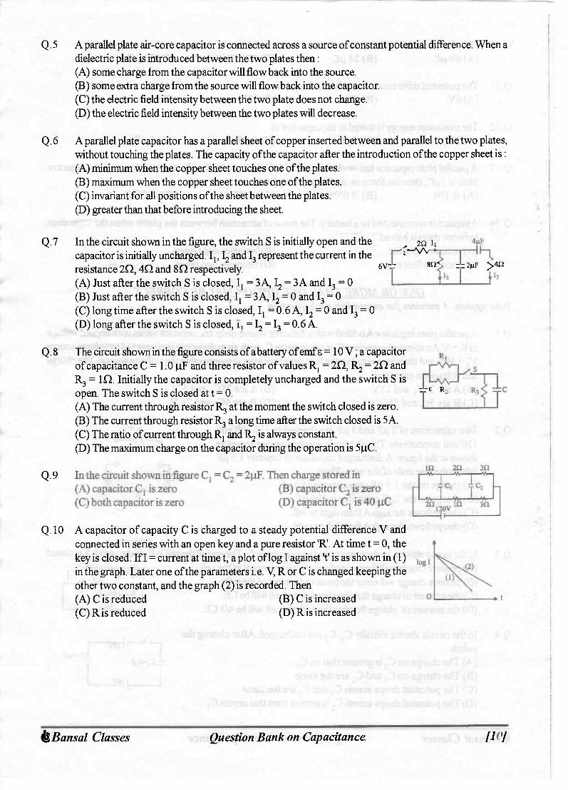
Q.5 A parallel plate air-core capacitor is connected across a source of constant potential difference. When a dielectric plate is introduced between the two plates then: (A) some charge from the capacitor will flow back into the source. (B) some extra charge from the source will flow back into the capacitor. (C) the electric field intensity between the two plate does not change. (D) the electric field intensity between the two plates will decrease.
Q.6 A parallel plate capacitor has a parallel sheet of copper inserted between and parallel to the two plates, without touching the plates. The capacity of the capacitor after the introduction of the copper sheet is: (A) minimum when the copper sheet touches one of the plates. (B) maximum when the copper sheet touches one of the plates. (C) invariant for all positions of the sheet between the plates. (D) greater than that before introducing the sheet.
Q.7 In the circuit shown in the figure, the switch S is initially open and the capacitor is initially uncharged. Ij, \ and I 3 represent the current in the resistance 2Q, 4f l and 8Q respectively. (A) Just after the switch S is closed, Ij = 3 A I2 = ^ A and I 3 = 0 (B) Just after the switch S is closed, I, = 3 A, I 2 = 0 and I 3 = 0 (C) long time after the switch S is closed, Ij = 0.6 A, I 2 = 0 and I 3 = 0 (D) long after the switch S is closed, = I 2 = I 3 = 0.6 A.
6VTT . 2Q ij r—w
812*- rjz 2|xF >412
Q.8 The circuit shown in the figure consists of a battery of emf s = 10 V; a capacitor of capacitance C = 1.0 pF and three resistor of values R, = 2Q, 1^ = 2 0 and R 3 = i n . Initially the capacitor is completely uncharged and the switch S is open. The switch S is closed at t = 0. (A) The current through resistor R 3 at the moment the switch closed is zero. (B) The current through resistor R 3 a long time after the switch closed is 5 A. (C) The ratio of current through Rj and I^ is always constant. (D) The maximum charge on the capacitor during the operation is 5pC.
•±"E R.
Q.9
Q.10 A capacitor of capacity C is charged to a steady potential difference V and connected in series with an open key and a pure resistor 'R'. At time t = 0, the key is closed. If I = current at time t, a plot of log I against't' is as shown in (1) in the graph. Later one of the parameters i. e. V, R or C is changed keeping the other two constant, and the graph (2) is recorded. Then (A) C is reduced (B) C is increased (C) R is reduced (D) R is increased
(fe Bansal Classes Question Bank on Capacitance [13]
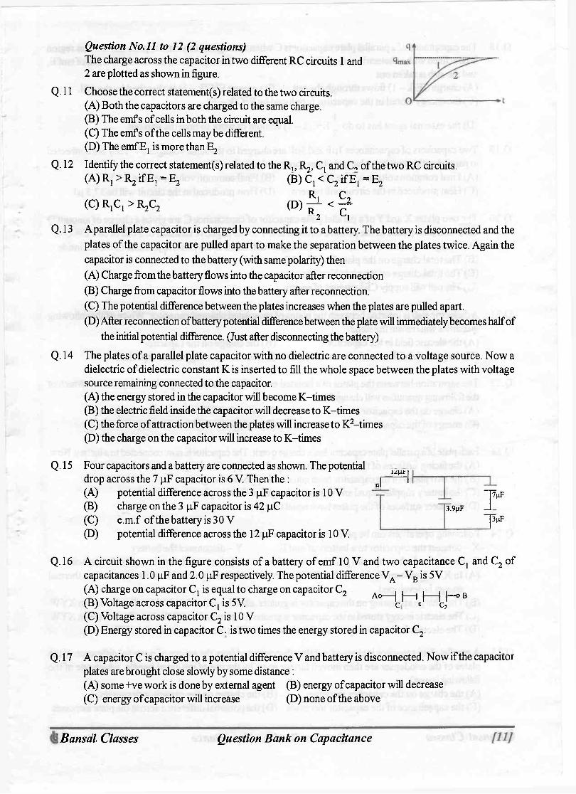
Question No. 11 to 12 (2 questions) The charge across the capacitor in two different RC circuits 1 and 2 are plotted as shown in figure.
Q.l l Choose the correct statement(s) related to the two circuits. (A) Both the capacitors are charged to the same charge. (B) The emf s of cells in both the circuit are equal. (C) The emf s of the cells may be different. (D) The emf E t is more than E 2
Q.12 Identify the correct statement(s) related to the R,, R^ Cj and C„ of the two RC circuits. ( A ) R 1 > R 2 i f E , = E 2 ( B ) C 1 < C 2 i f E 1 = E 2
(C) RjCJ > R.C, (D) f 1 < ^ 2 C 1
Q.13 Aparallel plate capacitor is charged by connecting it to a battery. The battery is disconnected and the plates of the capacitor are pulled apart to make the separation between the plates twice. Again the capacitor is connected to the battery (with same polarity) then (A) Charge from the battery flows into the capacitor after reconnection (B) Charge from capacitor flows into the battery after reconnection. (C) The potential difference between the plates increases when the plates are pulled apart. (D) After reconnection of battery potential difference between the plate will immediately becomes half of
the initial potential difference. (Just after disconnecting the battery) Q. 14 The plates of a parallel plate capacitor with no dielectric are connected to a voltage source. Now a
dielectric of dielectric constant K is inserted to fill the whole space between the plates with voltage source remaining connected to the capacitor. (A) the energy stored in the capacitor will become K-times (B) the electric field inside the capacitor will decrease to K-times (C) the force of attraction between the plates will increase to K 2-times (D) the charge on the capacitor will increase to K-times
Q. 15 Four capacitors and a batteiy are connected as shown. The potential drop across the 7 pF capacitor is 6 V. Then the : J H (A) potential difference across the 3 pF capacitor is 10 V (B) charge on the 3 pF capacitor is 42 pC (C) e.m.f. of the battery is 3 0 V (D) potential difference across the 12 pF capacitor is 10 V.
3.9(.IF
J7nF "puF
Q. 16 A circuit shown in the figure consists of a battery of emf 10 V and two capacitance C, and C 2 of capacitances 1.0 pF and 2.0 pF respectively. The potential difference V A - V B is 5 V
A o — | | — | | — | | o B (A) charge on capacitor Cj is equal to charge on capacitor C 2
(B) Voltage across capacitor Cj is 5V. c' e q, (C) Voltage across capacitor C 2 is 10 V (D) Energy stored in capacitor C. is two times the energy stored in capacitor C 2 .
Q.17 A capacitor C is charged to a potential difference V and batteiy is disconnected. Now if the capacitor plates are brought close slowly by some di stance: (A) some +ve work is done by external agent (B) energy of capacitor will decrease (C) energy of capacitor will increase (D) none of the above
(fe Bansal Classes Question Bank on Capacitance [13]
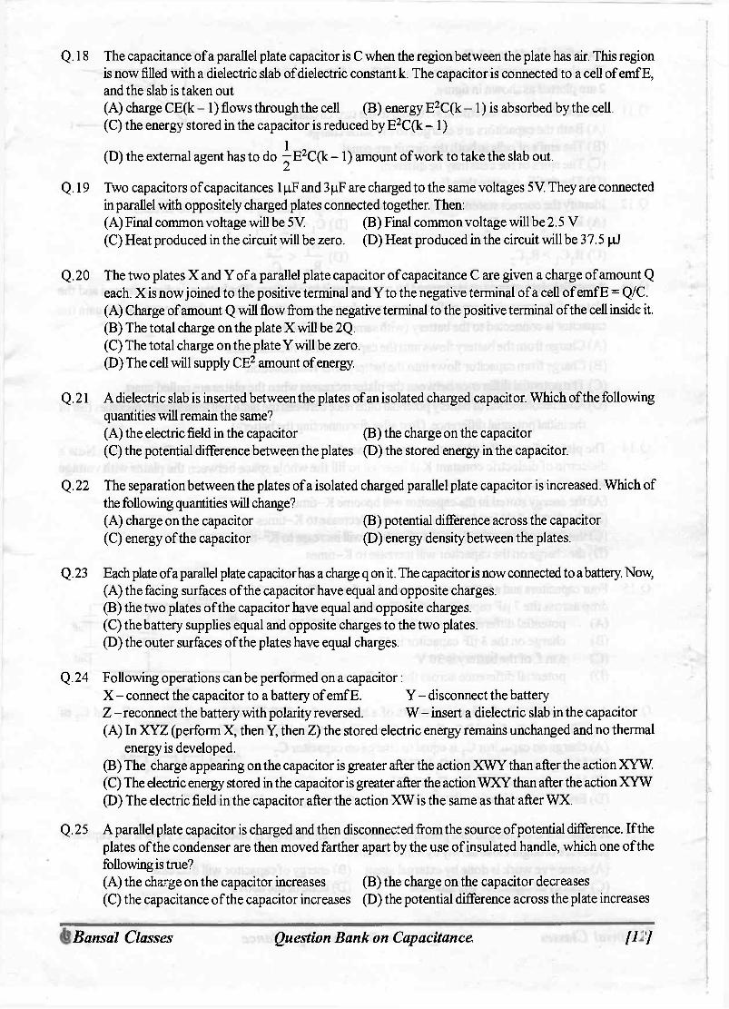
Q.18 The capacitance of a parallel plate capacitor is C when the region between the plate has air. This region is now filled with a dielectric slab of dielectric constant k. The capacitor is connected to a cell of emf E, and the slab is taken out (A) charge CE(k - 1 ) flows through the cell (B) energy E 2C(k - 1) is absorbed by the cell. (C) the energy stored in the capacitor is reduced by E 2C(k - 1 ) (D) the external agent has to do ^E 2 C(k - 1 ) amount ofwork to take the slab out.
Q.19 Two capacitors of capacitances 1 pF and 3 pF are charged to the same voltages 5 V. They are connected in parallel with oppositely charged plates connected together. Then: (A) Final common voltage will be 5 V (B) Final common voltage will be 2.5 V (C) Heat produced in the circuit will be zero. (D) Heat produced in the circuit will be 37.5 pJ
Q. 20 The two plates X and Y of a parallel plate capacitor of capacitance C are given a charge of amount Q each. X is now joined to the positive terminal and Yto the negative terminal of a cell of emf E = Q/C. (A) Charge of amount Q will flow from the negative terminal to the positive terminal of the cell inside it (B) The total charge on the plate X will be 2Q. (C) The total charge on the plate Y will be zero. (D) The cell will supply CE 2 amount of energy.
Q.21 A dielectric slab is inserted between the plates of an isolated charged capacitor. Which of the following quantities will remain the same? (A) the electric field in the capacitor (B) the charge on the capacitor (C) the potential difference between the plates (D) the stored energy in the capacitor.
Q.22 The separation between the plates of a isolated charged parallel plate capacitor is increased. Which of the following quantities will change? (A) charge on the capacitor (B) potential difference across the capacitor (C) energy of the capacitor (D) energy density between the plates.
Q.23 Each plate of a parallel plate capacitor has a charge q on it. The capacitor is now connected to a battery. Now, (A) the facing surfaces of the capacitor have equal and opposite charges. (B) the two plates of the capacitor have equal and opposite charges. (C) the battery supplies equal and opposite charges to the two plates. (D) the outer surfaces of the plates have equal charges.
Q. 24 Following operations can be performed on a capacitor: X - connect the capacitor to a battery of emf E. Y - disconnect the battery Z - reconnect the battery with polarity reversed. W - insert a dielectric slab in the capacitor (A) In XYZ (perform X, then Y, then Z) the stored electric energy remains unchanged and no thermal
energy is developed. (B) The charge appearing on the capacitor is greater after the action XWY than after the action XYW. (C) The electric energy stored in the capacitor is greater after the action WXY than after the action XYW. (D) The electric field in the capacitor after the action XW is the same as that after WX.
Q.25 A parallel plate capacitor is charged and then disconnected from the source of potential difference. If the plates of the condenser are then moved farther apart by the use of insulated handle, which one of the following is true? (A) the charge on the capacitor increases (B) the charge on the capacitor decreases (C) the capacitance of the capacitor increases (D) the potential difference across the plate increases
(fe Bansal Classes Question Bank on Capacitance [13]
Q.26 Aparallel plate capacitor is charged and then disconnected from the source steady E.M.F. The plates are then drawn apart farther. Again it is connected to the same source. Then: (A) the potential difference across the plate increases, while the plates are being drawn apart. (B) the charge from the capacitor flows into the source, when the capacitor is reconnected. (C) more charge is drawn to the capacitor from the source, during the reconnection. (D) the electric intensity between the plates remains constant during the drawing apart of plates.
Q.27 When a parallel plates capacitor is connected to a source of constant potential difference, (A) all the charge drawn from the source is stored in the capacitor. (B) all the energy drawn from the source is stored in the capacitor. (C) the potential difference across the capacitor grows very rapidly initially and this rate decreases to
zero eventually. (D) the capacity of the capacitor increases with the increase of the charge in the capacitor.
Q.28 When two identical capacitors are charged individually to different potentials and connected parallel to each other, after disconnecting them from the source: (A) net charge on connected plates is less than the sum of initial individual charges. (B) net charge on connected plates equals the sum of initial charges. (C) the net potential difference across them is different from the sum of the individual initial potential differences. (D) the net energy stored in the two capacitors is less than the sum of the initial individual energies.
Q. 29 Aparallel plate capacitor of plate area A and plate seperation d is charged to potential difference V and then the battery is disconnected. A slab of dielectric constant K is then inserted between the plates of the capacitor so as to fill the space between the plates. If Q, E and W denote respectively, the magnitude of charge on each plate, the electric field between the plates (after the slab is inserted) and the work done on the system, in question, in the process of inserting the slab, then
e 0 AV s 0 KAV V £ AV 2
1 - 1 K Q. 3 0 A parallel plate capacitor is connected to a battery. The quantities charge, voltage, electric field and
energy associated with the capacitor are given by Q 0 , VQ, E 0 and U 0 respectively. A dielectric slab is introduced between plates of capacitor but battery is still in connection. The corresponding quantities now given by Q, V, E and U related to previous ones are ( A ) Q > Q 0 (B) V > V 0 (C) E > E q ( D ) U < U 0
Q.31 A parallel-plate capacitor is connected to a cell. Its positive plate A and its negative plate B have charges +Q and - Q respectively. A third plate C, identical to A and B, with charge +Q, is now introduced midway between A and B, parallel to them. Which of the following are correct?
3Q (A) The charge on the inner face of B is now —— (B) There is no change in the potential difference between A and B. (C) The potential difference between A and C is one-third of the potential difference betweenB and C. (D) The charge on the inner face of A is now Q/ 2.
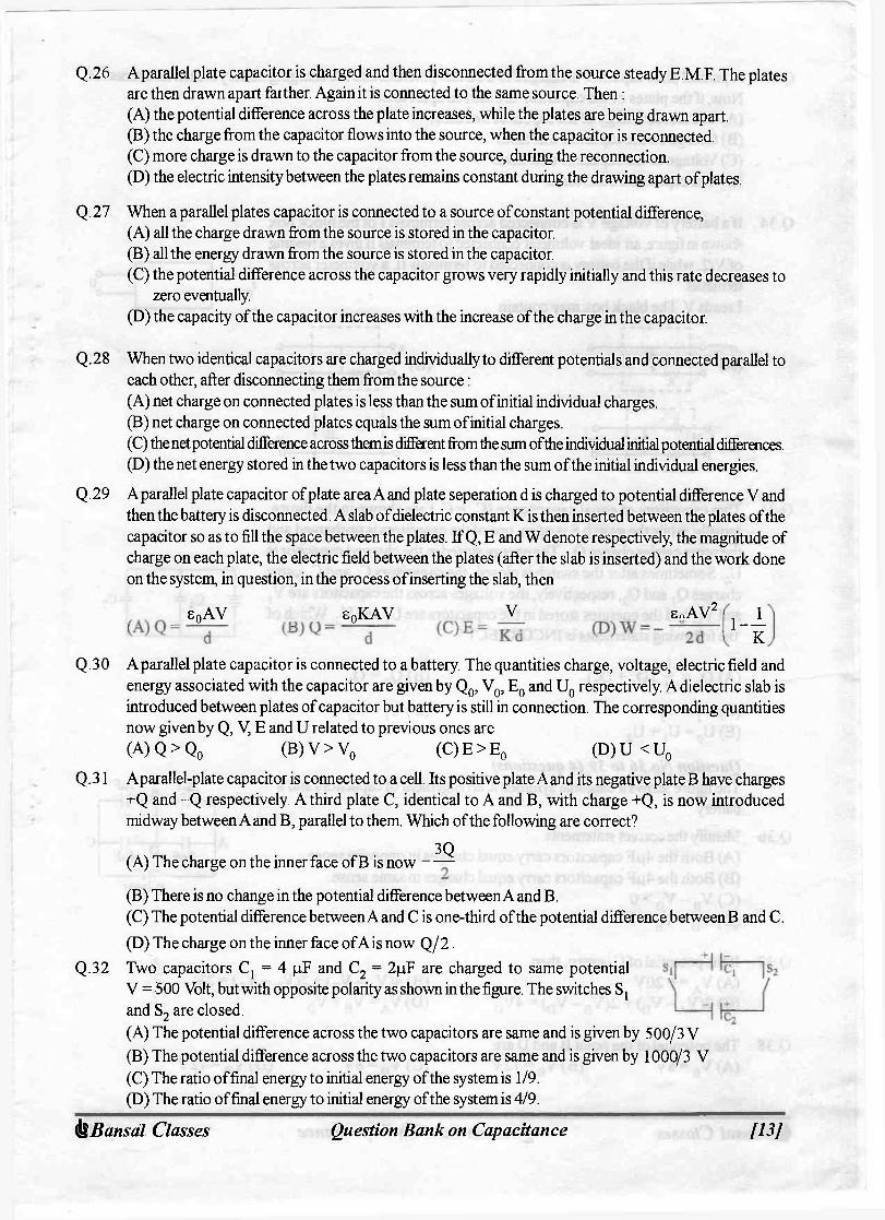
Q.32 Two capacitors Cj = 4 pF and C 2 = 2pF are charged to same potential V = 500 Volt, but with opposite polarity as shown in the figure. The switches S t
and S 2 are closed. (A) The potential difference across the two capacitors are same and is given by 500/3 V (B) The potential difference across the two capacitors are same and is given by 1000/3 V (C) The ratio of final energy to initial energy of the system is 1/9. (D) The ratio of final energy to initial energy of the system is 4/9.
(fe Bansal Classes Question Bank on Capacitance [13]
Q. 33 A parallel plate capacitor is charged to a certain potential and the charging battery is then disconnected. Now, if the plates of the capacitor are moved apart then: (A) The stored energy of the capacitor increases (B) Charge on the capacitor increases (C) Voltage of the capacitor decreases (D) The capacitance increases
Q. 34 If a battery of voltage V is connected across terminals I of the block box shown in figure, an ideal voltmeter connected to terminals II gives a reading of V/2, while if the battery is connected to terminals II, a voltmeter across terrninals I reads V. The black box may contain
(A) i
O-J I ! O—I—vwv-
l R
iR
' R O—I—vwv-(C) ER O—i—vwv-
l R
-o 11
- o 11 -o
(B) 1 1 c 1 T
(D)1. i i 1 i 1 1 j£) J ! T 1
Q.35 Two capacitors of equal capacitance (Cj = C 2 ) are shown in the figure. Initially, while the switch S is open, one of the capacitors is uncharged and the other carries charge Q 0 . The energy stored in the charged capacitor is U 0 . Sometimes after the switch is closed, the capacitors Cj and C 2 carry charges Qj and Q 2 , respectively; the voltages across the capacitors are V {
and V 2 ; and the energies stored in the capacitors are Uj and U 2 . Which of the following statements is INCORRECT ?
4= Co
(A) Q0 = - (Qj + Q2) ( C ) V j = V 2
(E)U 0 = U j + U 2
(B) Qj = Q2
(D)Uj = U 2
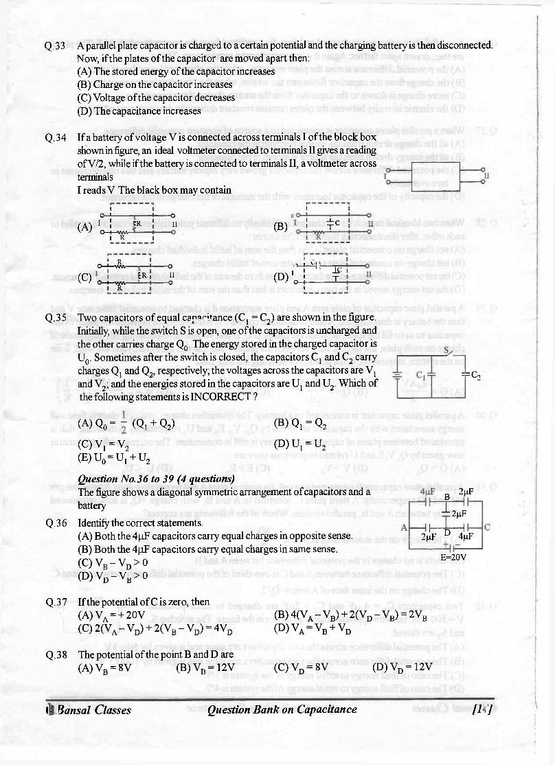
Question No. 3 6 to 39 (4 questions) The figure shows a diagonal symmetric arrangement of capacitors and a battery
Q. 3 6 Identify the correct statements. (A) Both the 4pF capacitors carry equal charges in opposite sense. (B) Both the 4pF capacitors carry equal charges in same sense. ( C ) V B - V D > 0 ( D ) V d - V B > 0
fi 2\xF
h T 2(xF
2 (iF ° 4|iF E=20V
Q. 3 7 If the potential of C is zero, then (A) V A = + 20 V ( C ) 2 ( V A - V d ) + 2 ( V B - V d ) = 4V D
( B ) 4 ( V A - V B ) + 2 ( V D - V B ) = 2V B
( D ) V A = V B + V D
Q. 3 8 The potential of the point B and D are (A) V B = 8 V (B) V B = 12V (C) V D = 8 V ( D ) V d = 1 2 V
(fe Bansal Classes Question Bank on Capacitance [13]

Q.39 The value of charge q 1 ; q 2 and q 3 as shown in the figure are (A) qj = 32 pC ; q 2 = 24 pC ; q 3 = - 8 pC (B) q { = 48 pC ; q 2 = 16 pC ; q 3 = + 8 pC (C) qj = 32 pC ; q 2 = 24 pC ; q 3 = + 8 pC (D) q ( = 3 pC ; q 2 = 4 pC ; q 3 = + 2 pC
qi -HP B 12 •i-l ^
q2 D
E=20V qi
Q.40 If Q is the charge on the plates of a capacitor of capacitance C, V the potential difference between the plates, A the area of each plate and d the distance between the plates, the force of attraction between the plates is
(A) — v 7 2 V 8 o A
(B) r CV2 A
< o j CV2
v A s o J 7IE0d'
-J.
(fe Bansal Classes Question Bank on Capacitance [13]

l9ll djuvjpvdvj uo yjuvg uoijS3ri() S3SSVJ3 jvsuvg^
ONLY ONE OPTION IS CORRECT
Q.l B Q.2 A Q.3 C Q.4 A Q.5 B Q.6 A Q.7 B Q.8 C Q.9 D Q.10 A Q.l l B Q.12 D Q.13 C Q.14 A Q.15 C Q.16 C 0.17 B Q.18 B Q.19 B Q.20 B Q.21 A Q.22 C Q.23 B Q.24 B Q.25 D Q.26 B Q.27 A Q.28 A Q.29 D Q.30 B Q.31 C Q.32 D Q.33 B Q.34 C Q.35 A Q.36 B Q.37 B Q.38 B Q.39 A Q.40 D Q.41 D Q.42 C Q.43 B Q.44 D Q.45 D Q.46 B Q.47 C Q.48 C Q.49 B Q.50 D Q.51
h Q.52 B Q.53 B Q.54 C
ONE OR MORE THAN ONE OPTION MAY BE CORRECT
Q.l B,C Q.2 AB,C Q.3 A D Q.4 B Q.5 B,C Q.6 C,D Q.7 B Q.8 A,BX\D Q.9 B,D Q.10 B Q.l l A,C Q.12 D Q.13 B,C Q.14 A,C,D Q.15 B,C,D Q.16 AD Q.17 B Q.18 AB,D Q.19 B,D Q.20 A,B,C.D Q.21 B Q.22 B,C Q.23 AC,D Q.24 B,C,D Q.25 D Q.26 AB,D Q.27 A,C Q.28 B,C,D Q.29 A,C,D Q.30 A Q.31 A B , C , D Q.32 A,C Q.33 A Q.34 D Q.35 E Q.36 B , C Q.37 A,B,C,D Q.38 B,C Q.39 c Q.40 AB
A 3)1 X3MSNV