cancellable biometric using matrix … mukhaiyar cancellable biometric using matrix approaches...
TRANSCRIPT
Riki Mukhaiyar
CANCELLABLE BIOMETRIC
USING MATRIX APPROACHES
DOCTOR OF PHILOSOPHY
SCHOOL OF ELECTRICAL AND ELECTRONIC ENGINEERING
NEWCASTLE UNIVERSITY
UNITED KINGDOM
AUGUST 2015

A THESIS SUBMITTED TO
THE FACULTY OF SCIENCE, AGRICULTURE, AND ENGINEERING
IN PARTIAL FULFILMENT OF THE REQUIREMENTS FOR
THE DEGREE OF
DOCTOR OF PHILOSOPHY

NEWCASTLE UNIVERSITY
SCHOOL OF ELECTRICAL AND ELECTRONIC
ENGINEERING
I, Riki Mukhaiyar, confirm that this thesis and work presented in it are
my own achievement.
I have read and understand the penalties associated with plagiarism.
Signed:
Date: 26/08/2015
i
Abstract
Cancellable biometrics endeavour to hide the appearance of a biometric image into a
transformed template which prevents the outsider from recognising whom the biometric
belongs to. Current research into cancellable biometric methodologies concentrates on the
details of biometric traits. This approach has a drawback which cannot possibly be
implemented with other biometric technology.
To address this problem, this thesis contributes to development of a novel concept for the
feature transformation of biometric technology, especially for fingerprints, by utilizing
several matrix operations to provide an alternative algorithm in order to produce multi-
implementation of the cancellable system. The matrix operations generate the feature element
of the input fingerprint image in an irrevocable form of output fingerprint template by
ignoring the type of biometric traits unique to fingerprints; thus, the cancellable algorithm can
be implemented in different biometrics technologies. The implementation offers a new
concept in generating a cancellable template by considering a sequential procedure for the
fingerprint processing, in order to allow the authentication process to succeed in
authenticating an enquired input. For example, a region of interest (RoI) step is required to
provide a square form input to support the system working in a matrix domain. Meanwhile,
the input fingerprints are mostly in rectangular form.
This thesis contributes a new approach to selecting a certain area of a fingerprint by utilizing
the density of ridge frequency and orientation. The implementation of these two enhancement
steps reduces the excision process of this significant region of the fingerprint by avoiding the
involvement of a non-feature area. Meanwhile, to avoid obtaining an un classified fingerprint,
this thesis offers a new approach to the fingerprint image classification process entailing three
requirements in classifying the fingerprint: the core point and its number, ridge frequency,
and ridge direction; whilst the tented arch (TA) is only an additional requirement. The
proposed idea increases both the percentage accuracy in classifying fingerprints and time
consuming of the system. For Example, the accuracy of the fingerprint classification
improves from less than 41 per cent of the fingerprint to 86.48 per cent in average for all of
databases.

ii
Acknowledgement
Alhamdulillah rabbil ‘alamin. Thanks to Allah Azza Wa Jalla for allowing me to finish this
thesis. I am with humility thankful to my supervisors, Prof. Satnam S. Dlay and Dr. Wai Lok
Woo, for their support, understanding, encouragement, and helping me to identify, desing,
conduct, and complete the research.
Furthermore, I want to give my appreciation to the Directorate General of Higher Education
of the Ministry of Education and Culture of the Republic of Indonesia for the scholarship to
finance my Ph.D study at Newcastle University, United Kingdom. Finally, the most
important thanks I dedicate to my parents: papa Professor Mukhaiyar and mama Hirnawati,
my wife: Sylvia Utari, my son: Muhammad Azzam Riki Mukhaiyar, my daughter: Mahdiya
Aisyah Riki Mukhaiyar, my sister: Utriweni Mukhaiyar, and my brother: Hadi Mukhaiyar for
their enduring love.

iii
Contents
ABSTRACT i
ACKNOWLEDGEMENT ii
CONTENTS iii
LIST OF FIGURES vii
LIST OF TABLES xi
ABBREVIATIONS xiv
LIST OF PUBLICATIONS xvi
1. INTRODUCTION
1.1. Biometric 1
1.2. Cancellable Biometrics 3
1.3. Thesis Aims and Objectives 6
1.4. Contributions 7
1.5. Thesis Outline 8
2. CANCELLABLE BIOMETRICS
2.1. Introduction 10
2.2. The Non-Invertible Issue 13
2.3. Re-Issuing 15
2.4. Accuracy Performance 16
2.5. Matrix Operations 17
2.5.1. Elementary Row Operations 18

iv
2.5.2. Kronecker Product Operation 19
2.6. Summary 20
3. BIOMETRICS FINGERPRINT
3.1. Introduction 22
3.2. Fingerprint Enhancement 25
3.3. Core-Point Identification 27
3.4. Region of Interest 28
3.5. Fingerprint Classification 31
3.6. Minutiae Extraction 33
3.7. Summary 34
4. MATRICES OPERATIONS AND CANCELLABLE FINGERPRINT
4.1. Introduction 36
4.2. Basic Idea of Generating Cancellable Features 37
4.3. Matrix Implementation 39
4.4. Algorithm Outline 43
4.5. Experimental Results and Discussions 44
4.6. Summary 52
5. DEPENDABLE CANCELLABLE FINGERPRINT
5.1. Introduction 55
5.2. Fingerprint Enhancement 56
5.3. Core-Point Identification 57
5.4. RoI 58
5.5. Fingerprint Classification 60
5.6. Minutiae Extraction 61
5.7. Experimental Results 63

v
5.7.1. Database FVC 2002 64
5.7.2. Database FVC 2004 66
5.7.3. Database BRC 67
5.8. Discussions 68
5.9. Summary 81
6. PERFORMANCE ANALYSIS
6.1. Introduction 84
6.2. Error Rates Evaluation 84
6.3. Evaluation of Time Taken 98
6.4. Evaluation of Matrices Operations Requirements 101
6.4.1. The Size of the Arbitrary Matrix of the KP Operation 101
6.4.2. The Zero Rows and Columns of the ERO Operation 103
6.5. Discussions 107
6.6. Summary 110
7. CONCLUSION AND FUTURE WORK
7.1. Conclusion 112
7.2. Recommendations for Future Work 117
REFERENCE 119
APPENDIX 131
A.1. Elementary Row Operation 131
A.2. Kronecker Product 137
A.2.1. Definition and Examples 137
A.2.2. Properties of the Kronecker Product 139
A.3. Inverse Matrix Operations 144
A.3.1. Inverses of Larger Matrix 144

vi
A.3.2. System Solving using the Inverse of the Coefficient Matrix 145
vii
List of Figures
Figure 2.1. Cancellable Templates from Different Transforms 17
Figure 2.2. Re-Issuing in Cancellable Biometrics 19
Figure 3.1. Core-Point Detection using Ridge Frequency, and 28
Orientation Steps of Fingerprint
Figure 3.2. Fingerprint and Its Core-point and Delta 29
Figure 3.3. Region of Interest Step 30
Figure 3.4. Examples of the Five Commonly Used of the Fingerprints Classes 31
Under the Galton-Henry Classification Scheme
Figure 3.5. Examples of the Minutiae Extraction of Two Different Fingerprints 34
Database Sources (FVC2002 and BRC)
Figure 4.1. Three Approaches in Generating a Cancellable Image using 44
Several Matrix Operations
Figure 4.2. Implementation Result of the First Procedure of the Research Outline 45
Figure 4.3. Image as a Result of Elementary Row Operation (the Cancellable 47
Fingerprint Image)
Figure 4.4. Another Approach of the Procedure of the Proposed Research Outline 48
(720 x 720 pixel) by Exchanging the Placing Combination of
the Kronecker Operation
Figure 4.5. The Kronecker Product of the Second Alternative Procedure of 49
the Research Outline (480 x 720 pixels)
Figure 4.6. Images of the Cancellable Algorithm 50
Figure 4.7. The Third Procesure of the Research Outline 51
Figure 4.8. Illustration Flow of the First Procedure of the Research Outline 52
viii
Figure 4.9. Illustration Flow of the Second Procedure of the Research Outline 53
Figure 4.10. Illustration Flow of the Third Procedure of the Research Outline 53
Figure 4.11. Illustration of the Importance of Pre-Processing Step for Fingerprint 54
Figure 5.1. RoI Procedures for Fingerprint Image Un-Centred Core-Point 58
Figure 5.2. Another RoI Result 59
Figure 5.3. Examples of a Ridge Ending and Bifurcation 62
Figure 5.4. Eight Neighbourhood Pixels Scanned in an Anti-Clockwise Direction 62
of the Crossing Number (CN)
Figure 5.5. The Candidate of Ridge Ending and Ridge Bifurcation 63
(Illustration using the Properties of CN)
Figure 5.6. Enhancement Process’ Result for FVC2004DB1 and FVC2002DB1 69
Figure 5.7. The Enhancement Process Omits the Noise of 70
the Original Fingerprint
Figure 5.8. Comparison Results for an Original Fingerprint 71
Figure 5.9. Core-point Identification Result 72
Figure 5.10. Step Process of RoI 73
Figure 5.11. Ridge Orientation of Fingeprint 101_1.tif (FVC2002 DB1_B);
Indicated as Right Loop Class Fingerprint 78
Figure 5.12. Indicated as a New Type of Fingprint (Besides Henry-Galton Scheme) 80
Figure 5.13. Frequency Display for Cancellable Result of Fingeprint 81
Figure 6.1. Original RoI Fingerprint of FVC2002DB1 used as the Established 87
Database
Figure 6.2. Original RoI Fingerprint of FVC2002DB2 used as the Established 88
Database
Figure 6.3. Original RoI Fingerprint of FVC2002DB3 used as the Established 89
ix
Database
Figure 6.4. Original RoI Fingerprint of FVC2002DB4 used as the Established 90
Database
Figure 6.5. Original RoI Fingerprint of FVC2004DB1 used as the Established 91
Database
Figure 6.6. Original RoI Fingerprint of FVC2004DB2 used as the Established 92
Database
Figure 6.7. Original RoI Fingerprint of FVC2004DB3 used as the Established 94
Database
Figure 6.8. Original RoI Fingerprint of FVC2004DB4 used as the Established 95
Database
Figure 6.9. Original RoI Fingerprint of BRCDB1Test used as the Established 96
Database
Figure 6.10. Original RoI Fingerprint of BRCDB1Training used as the Established 97
Database
Figure 6.11. Original RoI Fingerprint of BRCDB2 used as the Established 98
Database
Figure 6.12. Illustrating the Correlation between the Size of the Arbitrary Matrix and 102
Time Taken of the Process
Figure 6.13. Illustrating of the Original Feature of the Fingerprint 104
Figure 6.14 One Row of the Original Feature of the Fingerprint Replaced by 104
Zero Row
Figure 6.15 Two Rows of the Original Feature of the Fingerprint Replaced by 104
Zero Row
Figure 6.16 Three Rows of the Original Feature of the Fingerprint Replaced by 105

x
Zero Row
Figure 6.17 One Column of the Original Feature of the Fingerprint Replaced by 105
Zero Column
Figure 6.18 Two Columns of the Original Feature of the Fingerprint Replaced by 105
Zero Columns
Figure 6.19 Three Columns of the Original Feature of the Fingerprint Replaced by 106
Zero Columns
Figure 6.20. Illustration the Combination of the Zero Row and Column of the Image 106
Figure 6.21. The Unchanged Look of the Fingerprint Features after the Augmenting 107
Process of the Zero Row and Column into the Image
Figure A.1. Illustration of ERO 137
Figure A.2. Illustration of KP Operation 139

xi
List of Tables
Table 5.1. Properties of Crossing Number (CN) 63
Table 5.2. FVC 2002 Scanners/Technologies for each Database 64
Table 5.3. Results for Fingerprint Images of FVC2002 Database 65
Table 5.4. FVC 2003 Scanners/Technologies for each Database 66
Table 5.5. Results for Fingerprint Images of FVC2004 Database 66
Table 5.6. BRC Database Detail Information 67
Table 5.7. Results for Fingerprint Images of BRC Database 68
Table 5.8. Fingerprint Classification for Database FVC2002 under Galton-Henry 74
Classification Scheme
Table 5.9. Fingerprint Classification for Database FVC2002 based on 74
the Existence of the Fingerprint
Table 5.10. Fingerprint Classification for Database FVC2004 under Galton-Henry 75
classification Scheme
Table 5.11. Fingerprint Classification for Database FVC2004 based on 75
the Existence of the Fingerprint
Table 5.12. Fingerprint Classification for Database BRC DBI-Test under 76
Galton-Henry Classification Scheme
xii
Table 5.13. Fingerprint Classification for Database BRC DBI-Test based on 76
the Existence of the Fingerprint
Table 5.14. The Comparison Result of Three Different Databases in term of 79
classified, Unclassified, Indicated as Left/Right Loop, and False
classification Decision
Table 6.1. EER values FVC 2002 DB1 86
Table 6.2. EER values FVC 2002 DB2 87
Table 6.3. EER values FVC 2002 DB3 88
Table 6.4. EER values FVC 2002 DB4 89
Table 6.5. EER values FVC 2004 DB1 91
Table 6.6. EER values FVC 2004 DB2 92
Table 6.7. EER values FVC 2004 DB3 93
Table 6.8. EER values FVC 2004 DB4 94
Table 6.9. EER values BRC DB1 Test 95
Table 6.10. EER values BRC DB1 Training 96
Table 6.11. EER values BRC DB2 97
Table 6.12. Time Needed for Database FVC 2002 99
Table 6.13. Time Needed for Database FVC 2004 99
Table 6.14. Time Needed for Database BRC 100

xiii
Table 6.15. Correlation Between the Size Differences of the Input Fingerprint 101
and the Time Taken by the Process

xiv
Abbreviations
DNA Deoxyribonucleic Acid
DC Direct Current
ID Identity
PIN Personal Identification Number
ERO Elementary Row Operation
KP Kronecker Product Operation
RoI Region of Interest
TA Tented Arch
FAR False Accept Rates
FRR False Reject Rates
EER Equal Error Rate
MRF Markov Random Field
DC Direction of Curvature
GR Geometry of Region
AFIS Automatic Fingerprint Identification System
FVC Fingerprint Verification Competition
DB Database
BRC Biometrics Research Centre
INV Inverse Matrix Operation
CN Crossing Number
GAR Genuine Accepted Rate
CPU Central Processing Unit
GHz Giga Hertz

xv
RAM Random Access Memory
MATLAB Matrix Laboratory
dpi Dot per Inch
xvi
List of Publications
1. R. Mukhaiyar, S. S. Dlay, and W. L. Woo, “Alternative Approach in Generating
Cancellable Biometric by using Matrices Operations”, In the Proceedings of the 56th
International Symposium ELMAR-2014, pp. 163-166, Zadar, Croatia, Sept. 10-12,
2014.
2. R. Mukhaiyar, S. S. Dlay, and W. L. Woo, “Generating Cancellable Fingerprint using
Matrices Operations and Its Fingerprint Processing Requirements”, Journal
Submission, 2014.

1
Chapter 1
1. Introduction
1.1. Biometrics
Biometrics is a method of identifying human uniqueness based on one or several
features of either physical or behavioural characteristics. The physical characteristics relate to
the human body, such as fingerprints, the face, shape of the hand or palm, iris, retina, DNA,
or even human smell. Conversely, behavioural characteristics relate to human features, for
instance sound, typing rhythm, or the way a person walks. These characteristics are used to
identify humans based on the basic concepts of uniqueness, permanence, and collectivity.
Thus, the basic idea of biometric science is to use part of the human body as the key
or sign to obtain detailed information. This is either from the person whose part body part is
being used, or from someone who has a certain relationship with them. In computing science,
biometrics is specifically used as a requirement in managing private access and also in
controlling access given to an individual. In addition, it can also be used to identify a person
in a group which is under supervision.
One of the main biometric technologies that has been studied in detail is fingerprints.
Fingerprints can be defined as ‘a trace or an imprint of friction of contraction in most or all of
the surface of the human fingers’. The friction of contraction can be found on the palm of
one’s hand, fingers and toes, and on the skin of one’s foot. It consists of one, or more of
contraction unit that is connected to the imprint of the skin. This contraction is also known as
‘dermal contraction’.

2
Nowadays, the acquisition process of a fingerprint from its source is conducted
through direct fingerprint reading, also known as live fingerprint reader. This technology
relies on the principles of thermal and optical as well as silicon and ultrasonic sensing [1],
[2], [3] and is mostly used to read the fingerprint. It is based on the concept of changes to the
reflection in the area where a person’s finger touches the surface of the reader. All readers
that use optical technology consist of a source and a light sensor, and moreover a source of
specific reflection that can change a reflection if pressure occurs. Several of the type of
readers are equipped with processing equipment and a chip memory. The sensor used in this
technology is based on DC capacitance from fingers, and contain a layout of a capacitor with
a square shape that is implanted on the silicon chip. One side of the capacitor’s plate is on the
finger, while the other side, which contains a small area made from metal, is on the surface of
the chip, so that the finger is opposite the chip’s surface.
Another type of fingerprint reader technology is based on ultrasound, however, this is
less frequently used [4]. The initial concept of this technology is to use the ultrasound to
observe the surface of the pictures. The ultrasonic sensor will start moving and reading the
entire fingers for one or two seconds, as soon as the user place the fingers on a piece of glass
that is on the reader. The results will be saved in a particular unit in a database. This database
will be used when the application system for fingers requires confirmation by matching the
database with the fingers. If the fingers are recognized as one of the collection in the
database, the application system will accept them as the owner of the fingerprint. Otherwise
the application will state that it is an impostor. This process is known as the authentication
process of the fingerprint, and furthermore is also called the process of matching fingerprints.
Fingerprint matching techniques can be classified into two categories: minutiae-based
and correlation-based [5]. In the minutiae-based technique, the initial concept of matching the
fingerprint is achieved by obtaining the minutiae before arranging the placement, and then

3
ascertaining the connection between the minutiae and the fingers. Conversely, the correlation
based technique requires the exact location during the registration process. In addition, it is
also affected by the rotation and movement of the image [3], [6], [7], [8].
In this research, matrix operations are the main rule utilized in generating the
cancellable fingerprint template. The matrix operations are used to produce a transformed
template of fingerprint which is irrevocable to the original image of fingerprint. This
irrevocability factor is needed to protect the information of fingerprint to be compromised by
impostor. Initially, if a fingerprint is being processed in the matrix domain, then each pixel of
the image describes what the image is. This means that no noise is allowed as a part of the
image because the existence of noise may add specific information to the fingerprint feature.
In relation to the cancellable fingerprint, at the end of this process is the authentication step,
where even a small amount of noise will significantly affect the quality of the cancellable
feature and result in low precision in subsequent verification.
Thus, an early process to be accomplished in establishing a fingerprint is the
enhancement process. The result of this process will provide a fingerprint feature with the
precise value of all of its information, so that when it is mathematically processed with
matrices operations, there will be no unnecessary values contained within it. The result of
these operations will be the input of the cancellable system that is going to be created.
1.2. Cancellable Biometrics
The advances in information technology and increases in security concerns have
encouraged the rapid development of automatic personal identification systems in biometrics.
Biometric technology that accurately and automatically identifies a person based on their

4
physical and behavioural distinctions is considered to be crucial, given the need for
something reliable and capable of distinguishing whether the biometric owner is real or bogus
[9]. This technology is more preeminent than the token-based method or even other
knowledge-based methods which are based on traditional concepts, given that biometric
technology offers a particularly comfortable and secure process for its users.
Proving a person’s uniqueness using biometric technology is reliable, as human
physical characteristics are very difficult to imitate or falsify, compared with other methods
that use security codes and passwords, but requires a significant amount of important
memory. Biometric authentication can be located in various applications, such as in network
access and the workplace, log-on applications, data protection, the long distance access of
resources, website network security, e-government and e-commerce. Furthermore, biometric
technology will be needed to provide electronic banking services, as well as other financial
and investment transactions. In addition, retail sales, law enforcement, health and social
services also require this technology. It is expected to play an important role in clarifying a
person’s validity in larger scale trading networks that require authentication and protection
for its applications.
The implementation of biometric technology, whether on its own or combined with
other technologies such as smart cards, digital signatures and encrypted biometric keys, has
already been implemented in many areas. Thus, personal authentication through biometric
technology presents a new challenge in protecting personal data, which cannot be established
using traditional authentication methods. Moreover, users’ biometric data relating to health
and personal information will not be able to be changed, to be processed, or even illegally
distributed without the approval of eligible users [10], because during the cross-matching
process the system will also detect the invalidity of subjects that are registered by the eligible
users. Besides this if someone’s biometric data is stolen by ineligible users, the biometric
5
security system will be able to verify the identity of the impostor. This is possible since the
biometric data is permanent and interconnected with the data owner. Nevertheless, it is
undeniable that someone will lose his/her privacy as a consequence of using biometric data.
Due to a number of issues related to users’ privacy and security, many recent studies
have attempted to find a method to protect biometric systems from the possibility of misuse
by improving certain points that are considered to be deficient [11]. The security in this
method will have to be able to improve its security system, while efficiently running the
matching process and ensuring that it continues to identify appropriate biometric data. The
fact that biometric data is permanent and unique, as it is not owned by two or more persons,
means that offences against one’s personal data is less likely to happen, as in a traditional
system where a person’s identification, such as ID and PIN (personal identification number)
can be cancelled and remade.
Another approach proposed to protect biometric data is the biometric cryptosystem
[12]. This technology embeds key information onto the feature of biometrics as an additional
information about it. This information could not be revealed without a successful
authentication procedure. However, this technology has drawbacks related to unstable
recognition performance caused by the unreliable production of the key information [13].
With regards to sharing personal biometric data in public, for instance with
commercial companies, enforcement agencies, and government agencies, security and
privacy systems in biometric technology have been vastly improved by implementing
cancellable biometric technology [13], [14]. This is based on the fact that biometric data do
not vary much over time (permanence) and are very rarely shared by two people (uniqueness)
where privacy violations could occur if biometrics are misused or stolen. Traditional methods
for identifying people, for example, ID and personal identification numbers (PINs), can be
6
cancelled and reissued if the above privacy issues are compromised; however, this is not
possible with biometric data. Furthermore, there are privacy concerns about sharing biometric
data with commercial companies and law enforcement or government agencies.
Cancellable biometric technology uses biometric data that is intentionally transformed
instead of using the original biometric data in order to identify a person. The initial concept
of cancellable biometrics is that the system or the eligible user can automatically nullify the
registered data if his/her biometric data is being misused. The data in the cancellable
biometrics has to be different from the initial data and cannot be easily reconverted into its
original version, although the method of prior data transformation is known, and, moreover,
that the transformed version of the original data has been submitted. The original data can be
transformed into various types of data; however, the quality of the data does not decrease
compared to its fundamental version.
These advantages have motivated researchers in the biometric security field to find a
new and enhanced approach to generating a cancellable biometric template. A consideration
of the various possibilities to produce an algorithm for the cancellable biometric is a principle
reason for us to discuss the cancellable technology in this thesis.
1.3. Thesis Aims and Objectives
The main aim of this work is to produce a novel approach to the generation of
cancellable biometric features, particularly in fingerprint technology, by providing an
alternative method to produce a cancellable template that is able to be implemented not only
using one specific biometric technology. Theis aim can only be successfully achieved by first
7
understanding the basic requirements of a cancellable fingerprint. The objectives of these
requirements are:
- Produce a novel approach in generating cancellable biometric features,
particularly in fingerprint technology.
- Provide an alternative method to produce a cancellable template that is able to be
implemented not only for fingerprint technology but for another biometric
technologies as well.
- Provide all supporting fingerprint process algorithms, for instance fingerprint
enhancement and core-point identification to produce a dependable cancellable
fingerprint template.
1.4. Contributions
With current cancellable biometric methodologies, research is focusing onto the
details of biometric traits. Hence, the resulting algorithms cannot possibly be implemented in
other biometric technologies. For example, a cancellable fingerprint using the rotation and
orientation of the minutiae approach is not appropriate for generating cancellable face, iris, or
retina.
- Based on this disadvantage, a novel concept of utilizing matrix operations is
introduced in this thesis, to give an alternative algorithm which can produce a multi-
implementation cancellable biometric. The methodology developed in this thesis is
not limited to the proposed fingerprint only, as it is also able to be used for other
biometric technologies, for instance face, or palmprint.
8
- This research proposes a new concept with the aim of producing a cancellable
template. The concept requires a sequential procedure to guarantee that an established
and a queried biometric feature are compatible with an accepted one and incompatible
with a rejected one. This framework makes any applicant of this proposed approach to
be able to analyse less performance of the system.
- In generating the cancellable template, several requirements should be provided as an
input. One of the requirements is an input image form that is improved in a square
form shape and furthermore, a region of interest (RoI) algorithm is needed to select a
particular area of the fingerprint. In this thesis, a new method is applied by utilizing
the density of ridge-frequency and –orientation. The implementation of these two
enhancement steps reduces the excision of the important region of the fingerprint and
avoids involving the featureless area.
- To avoid obtaining an un-classified fingerprint, there are three principal requirements
of the proposed fingerprint classification image process: the core point and its
number, ridge frequency, and ridge direction; whilst the tented arch (TA) is only an
additional requirement. The proposed idea enhances the percentage accuracy in
classifying the fingerprint.
1.5. Thesis Outline
The thesis is organised into seven chapters. The first chapter presents an introduction
to this thesis and describes what biometrics and cancellable biometrics. This is followed by
the aims and objectives, thesis methodology and its contributions. In addition, the outline of
the thesis is also described in detail to illustrate its contents.
9
Chapter 2 focuses on producing cancellable biometrics along with the requirements
needed to achieve a reliable cancellable template, such as being non-invertible and re-issuing
and the authentication of performance. The existing cancellable biometric approaches are
considered so as to illustrate the uniqueness of the algorithm proposed in this thesis.
Nevertheless, the matrix operations used in this research are discussed as well.
Chapter 3 discusses fingerprints as a biometric technology requiring several methods
in order to produce a reliable cancellable template; such as, fingerprint enhancement, core-
point identification, region of interest, fingerprint classification, minutiae extraction and
fingerprint authentication.
Chapter 4 presents an innovative approach to generating a cancellable fingerprint
template using several matrix operations. A description of each operation is explained
algebraically to illustrate how the operation works. Moreover, the methodology for this
exclusive approach will be introduced along with results that indicate that the method is
reliable enough to generate a cancellable template.
Chapter 5 analyses the requirements regarding pre-processing, core point
identification, and region of interest, fingerprint classification, and minutiae extraction, in
order to support this distinctive approach, which produces a dependable cancellable biometric
methodology.
Chapter 6 focuses on a performance evaluation of the approaches discussed in
chapters 4 and 5, such as the evaluation of error rates, time taken and the requirements for
matrix operations.
Chapter 7 presents the overall conclusions of the thesis and moreover provides some
guidance for future work that has emerged from this research.
10
Chapter 2
2. Cancellable Biometrics
2.1. Introduction
The use of representations of identity such as passwords and ID cards is no longer
sufficient, as these can easily be shared or compromised. The security requirements in an
authentication system based on biometric technologies have to be the benchmark of the
system, as its characteristics will be permanently associated with the eligible user and cannot
be cancelled or withdrawn when used inappropriately. Someone’s biometric characteristics
cannot easily be replaced. So if an impostor misuses it, the data will be lost forever. As a
result, there is a possibility that the user will lose all access to the application using that
particular biometric data. In order to overcome this problem, the susceptibility of the
biometric system needs to be systematically identified and recognized [15], [16]. Thus,
protecting biometric information has become one of the main concerns, as well as a major
challenge to researchers, in this field.
Cancellable biometric is a concept where its biometric template is protected by
combining both the security system and replacement features in the biometric system. The
main idea of this system is the transformation of the cancellable biometric and the changing
of all images and features before proceeding to the matching process, whilst still maintaining
the natural characteristics of the cancellable scheme. An appropriate cancellable biometric
system has to have the following standards: to be distinctive and reusable, and with
unidirectional transformation and performance [17].
11
The transformation process implemented in various biometric technologies has
several functions such as: face identification [18], [19], [20], [21], signature identification
[22], [23], iris identification [24], [25], [26], [27], and voice identification [28], [29]. Many
recent papers consider that fingerprints are one of the technologies that are being widely
discussed for use in biometric systems [30], [31], [32], [33] & [34].
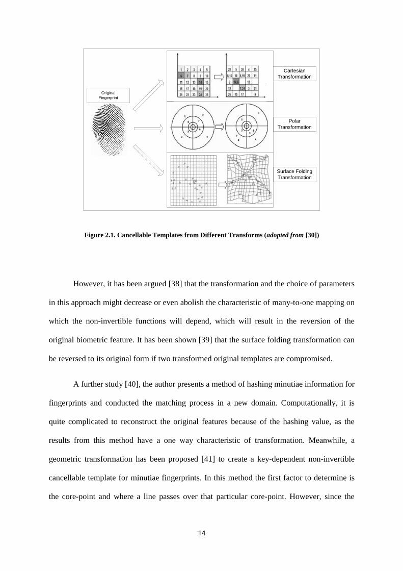
Three types of transformation have been recommended for implementation [30] with
fingerprint images: Cartesian transformation, polar transformation and image folding
transformation. However, the former two types have a disadvantage in relation to the
boundary issue. If the original minutiae point is away from its boundary and then divides the
area of the feature, as a result of minor distortion to the image alignment or if the original
fingerprint image is damaged, then the transformed version of the minutiae points will be
placed far from where it is supposed to be. Meanwhile, the third method relates to the
functional use of smoothing a local value to flip a fingerprint feature over the space.
Local smoothing function has been used to create a cancellable fingerprint template
by maintaining the original geometric connection (rotation and movement) between the
registered template and the questionable template after the transformation process is
conducted [33]. Therefore, the result from the template transformation can be used to identify
a person without requesting the alignment of the image fingerprint that is being used as an
input. However, this security method is in sufficient as protection for biometric data. For
example, an impostor might narrow down the candidates of the original minutiae design
based on limitations in the orientation continuity of the minutiae feature and the local
smoothing process of the transformation function.
Several investigations have been conducted regarding this issue. For instance, the
conversion of a fingerprint into a binary-string area is based on its minutiae series [34]. The
12
representations of binary numbers are transformed into an anonymous representation using a
unique personal key. According to the author, not only is the transformation non-invertible,
but also when it is misused by someone else, the template will disappear and can be renewed
by entering a different key. One of the advantages of this representation is that existing
methods, for instance bio-hashing could be implemented.
Alternatively, a secure method has been introduced to produce a template of a
cancellable fingerprint [35]. This method extracts a local image of the fingerprint filled with
minutiae in small pieces and subsequently transforms them into projection matrices without
changing the space between each minutia in those small pieces. However, the disadvantage
of this method is the poor accuracy of the transformation results. It can be noted that [36]
presents an idea in constructing a cancellable biometric system and secure sketches, in order
to protect the privacy of the biometric template while supervising the matching process
between the protected and referenced data. The standard process in cancellable biometrics is
to perform a transformation to create an unchangeable image and to produce a matching
process for those transformed images. In this technique a correction system is used on the
sketches which can be secured from the cancellable biometric system, resulting in a
procedure that supervises the appropriate matching process.
The geometric transformation system of the minutiae position has also been proposed
to create a template of cancellable fingerprints [37], which is useful in an alignment process.
In order to create a template of the cancellable fingerprint, a supervising parameter over the
encryption of minutiae features is conducted on the surrounding area of minutiae.
Subsequently, all the encrypted minutiae will be superimposed to form a protected template.
The parameters used to control minutiae encryption are created from the arranged minutiae
geometric. Compared with the parameters where the algorithms for the cancellable templates
13
use the information from the minutiae that have to be encrypted, this minutiae encryption can
guarantee the solidity of the non-invertibility concept.
2.2. The Non-Invertible Issue
In non-invertible transformation systems, a function, for example B, is designed to
transform the original biometric image into a new image within the scope of the domain
feature or signal. The B will serve as a key factor in protecting the cancellable template, as
well as determining if the template is non-invertible, reusable and variable. In view of the fact
that function B is not directly related to the original biometric image, then function B does
not have to be kept confidential.
his non-invertible transformation has been used where the fingerprint data is
transformed by the order of the three functions of non-invertible transformation [30]. As
shown in Figure 2.1, the three transformation functions are based on the Cartesian polar
concept and the surface folding transformation of the existing minutiae.
In general, the three transformation functions in Figure 2.1 enable more than one
minutia to be mapped onto the same points within the same transformation domain. This is
also known as many-to-one mapping. For example, two or more cells can be mapped into a
single cell in the Cartesian transformation, so that when the impostor discovers the key and
the transformation between the cells, the owner of the original cell will not be discovered, as
each minutia can refer to one of the cells at large. Therefore, this method provides certainty
over the resulting templates of non-invertible transformation.
14
Cartesian
Transformation
Polar
Transformation
Surface Folding
Transformation
Original
Fingerprint
Figure 2.1. Cancellable Templates from Different Transforms (adopted from [30])
However, it has been argued [38] that the transformation and the choice of parameters
in this approach might decrease or even abolish the characteristic of many-to-one mapping on
which the non-invertible functions will depend, which will result in the reversion of the
original biometric feature. It has been shown [39] that the surface folding transformation can
be reversed to its original form if two transformed original templates are compromised.
A further study [40], the author presents a method of hashing minutiae information for
fingerprints and conducted the matching process in a new domain. Computationally, it is
quite complicated to reconstruct the original features because of the hashing value, as the
results from this method have a one way characteristic of transformation. Meanwhile, a
geometric transformation has been proposed [41] to create a key-dependent non-invertible
cancellable template for minutiae fingerprints. In this method the first factor to determine is
the core-point and where a line passes over that particular core-point. However, since the
15
minutiae that are above the line reflect symmetrically below, this means that the template of
the transformation contains some information from its original template.
Cancellable biometrics offers a solution to protect the user’s privacy, as the client will
never be identified in the authentication process. This will guarantee that the protection of
template can be obtained at a feature level by using support from data in a non-invertible
transformation [42].
2.3. Re-Issuing
Biometrics automatically identifies and verifies someone based on his/her physical,
biological, and/or behavioural characteristics. Compared with traditional identification and
verification methods, biometrics is not only considered to be comfortable for its users, but
also minimizes the number of impostors and is more secure. Biometrics is also associated
into: the security system, through intelligent, and a security forces.
Nevertheless, there are several concerns related to the application of biometrics in
everyday life, such as security and privacy issues, along with the question of ensuring that it
is standardized. The principal concern is the issues that relate to biometric data security.
Unlike traditional identification methods, it is difficult to re-issue a person’s biometric data.
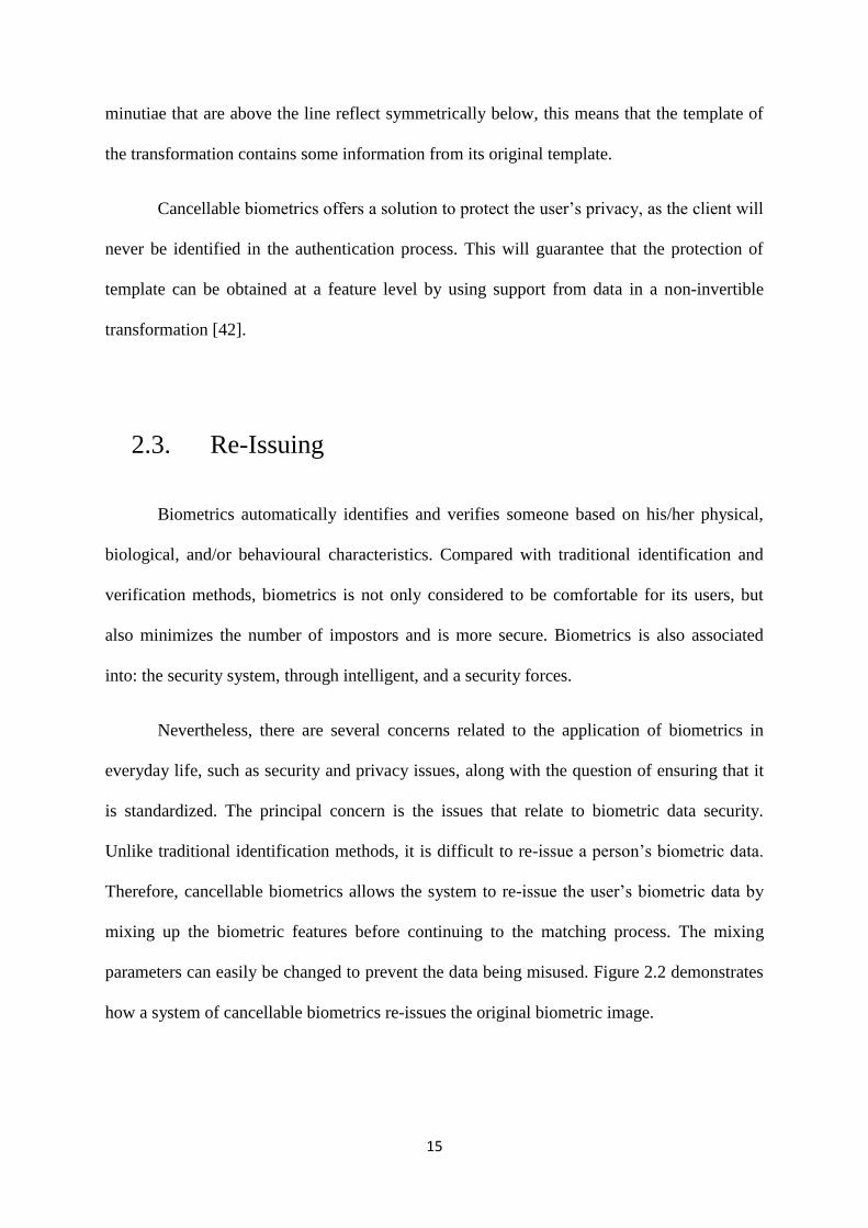
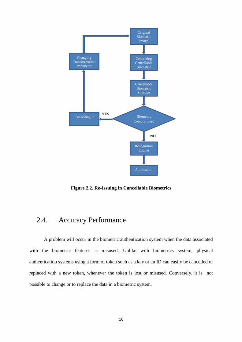
Therefore, cancellable biometrics allows the system to re-issue the user’s biometric data by
mixing up the biometric features before continuing to the matching process. The mixing
parameters can easily be changed to prevent the data being misused. Figure 2.2 demonstrates
how a system of cancellable biometrics re-issues the original biometric image.
16
Figure 2.2. Re-Issuing in Cancellable Biometrics
2.4. Accuracy Performance
A problem will occur in the biometric authentication system when the data associated
with the biometric features is misused. Unlike with biometrics system, physical
authentication systems using a form of token such as a key or an ID can easily be cancelled or
replaced with a new token, whenever the token is lost or misused. Conversely, it is not
possible to change or to replace the data in a biometric system.
Original
Biometric
Image
Generating
Cancellable
Biometric
Cancellable
Biometric
Strorage
Biometric
Compromised
Recognition
Engine
Application
Cancelling It
Changing
Transformation
Parameter
NO
YES
17
The performance evaluation of systems based on the biometric authentication is a
vital issue. Authentication systems will run the process by comparing the live biometric data
from the owner, which can belong to the owner or to others, with the original reference
template made by the system during the registration procedure. Matching the biometric
information entails calculating the degree of similarity between the live data in question and
the registered reference template. The results from this comparison process will be scored.
The false acceptance rate (FAR) and false rejection rate (FRR) are the important basic
performance measures of the matching process. The values of the rates for a threshold of
tolerance, however, combine levels of FAR and FRR in considering the security and
convenience of a biometric-based authentication system. In practice, the most challenging
aspect is to obtain a zero score for FAR and FRR. If the FAR score is higher, the system will
be more likely to recognize impostor data as genuine. If the FRR result is high the live data of
the owner will be recognized as an impostor, and vice versa. The impact of rejection in a
biometric system therefore becomes the main focus of discussion, and another index of
performance has been introduced where the point of FAR and FRR will be equal [43]. This
point is known as the equal error rate (EER), and a system will be considered as perfect if the
EER score is zero.
2.5. Matrix Operations
The objectives of this research are to produce a cancellable template for fingerprints
based on the similarity between the non-invertible need for the fingerprint template in the
cancellable system to be non-invertible and a non-invertible matrix in the matrices
operations. A template can be categorized as a cancellable template when it is non-invertible
18
to the original image. This also applies to the matrices. The matrices cannot be inverted when
satisfying three conditions. Firstly, there is at least one zero row. Subsequently, there is a row
that is a multiple of another row; and finally, the matrix form is not a square.
The first requirement can be achieved by using an elementary row operation (ERO),
where a selected row is multiplied by zero. Meanwhile, for the next requirement, it is rare to
find a row in the image system which is a multiple of another row; hence, it can be created
using ERO.
Furthermore, to ensure that the obtained cancellable matrix is completely masked and
to be able to meet the final requirement of the non-invertible matrix, each element of the
transformed matrix is multiplied by an arbitrary matrix/element in this research. This process
is called the Kronecker product or tensor product operation. By using this process, the
outcome comprises those matrices, and contains more numerous elements and an adjustable
matrix form (whether a rectangle or square matrix).
2.5.1. Elementary Row Operations (ERO)
Generally, Elementary Row Operations (ERO) can be defined as a multiplication and
addition force that is imposed on the matrix rows. The three operations corresponding to the
operations in rows of EROs are multiplied in the following way: a row by a non-zero
constant; interchanging two rows; and then adding a multiple of one row to another row [44].
The purpose of these operations is to acquire a solution in algebra or to obtain a new
form of matrix. For example, an arbitrary system of m linear equations in n unknowns can be
written as:

19
𝑎11𝑥1 + 𝑎12𝑥2 +⋯+ 𝑎1𝑛𝑥𝑛 = 𝑏1
𝑎21𝑥1 + 𝑎22𝑥2 +⋯+ 𝑎2𝑛𝑥𝑛 = 𝑏2
⋮
𝑎𝑚1𝑥1 + 𝑎𝑚2𝑥2 +⋯+ 𝑎𝑚𝑛𝑥𝑛 = 𝑏𝑚 (2.1)
wherex1, x2, x3, …,xn are the unknowns and the subscripted a’s and b’s denote constants.
The above equation can be simplified by writing down only the constant values in the form of
a rectangular matrix as follows:
[
𝑎11 𝑎12 ⋯ 𝑎1𝑛𝑎21 𝑎22 … 𝑎2𝑛⋮ ⋮ ⋱ ⋮𝑎𝑚1 𝑎𝑚2 ⋯ 𝑎𝑚𝑛
] [
𝑥1𝑥2⋮𝑥𝑛
] = [
𝑏1𝑏2⋮𝑏𝑚
] (2.2)
By using the three operations above, the unknown variables can be derived.
2.5.2. Kronecker Product (KP) Operation
The definition of the Kronecker product or tensor product can be noted as follows
[45]. Suppose 𝐴 ∈ ℝ𝑚×𝑛, 𝐵 ∈ ℝ𝑝×𝑞. Then the Kronecker product of A and B is defined as
the matrix:
𝐴⊗𝐵 = [𝑎11𝐵 ⋯ 𝑎1𝑛𝐵⋮ ⋱ ⋮
𝑎𝑚1𝐵 ⋯ 𝑎𝑚𝑛𝐵] ∈ ℝ𝑚𝑝×𝑛𝑞
Obviously, the same definition holds if A and B are complex-valued matrices.
20
There are two advantages that can be obtained using this operation. First of all, it is
able to change the value of each element of the original matrix. Secondly, if B has any kind of
matrix form, this means that a new larger matrix can be generated with different dimensions.
2.6. Summary
In this chapter, the discussion has centred on the reasons why security is more
important for biometric-based authentication systems than for non-biometrics systems. The
main reason is that a biometric is permanently associated with a user and cannot be revoked
or cancelled if compromised. In this case, if a biometric identifier is stolen and misused, it is
lost indefinitely and possibly for every application where that biometric is used. In order to
avoid any potential security crisis, vulnerabilities in the biometric system must be identified
and addressed systematically. Cancellable biometrics has been a challenging but essential
approach to protecting the privacy of biometric data. Therefore, protecting biometric
information is a major concern.
According to [30], there were eight places in the generic biometric system that is
vulnerable to be compromised. For example, some attacks can be perpetrated at the sensor
level and at the feature extractor level by presenting a fake biometric at the acquisition
process or resubmitting a sensor stored digitized biometrics signals. Meanwhile, in overriding
the feature extraction process, the feature extractor is attacked using a Trojan horse, so that is
produces feature sets pre-selected by the intruder.
Other attacks are related to the biometric templates generated by the feature extractor
module, which are stored in the database or matched against previously stored templates. The
biometric templates are the targets of the attacks either at the database level or at the

21
interconnecting channel level. Finally, the matcher and the output to the device application
can be attacked to override the system decision.
Cancellable biometrics is a concept where the biometric template is secured by
incorporating protection and replacement features into the biometrics. Fundamentally,
cancellable biometrics alter the biometric images or features before being matched. The
variability in distortion parameters offers the scheme its cancellable nature. A superior
cancellable biometrics formulation must fulfil four requirements: to be distinctive and
reusable, with unidirectional transformation and performance.
Based on these requirements, cancellable biometrics allows the system to re-issue the
biometrics for a user. The key idea of cancellable biometrics is to distort the biometric
image/signal/features before matching. The distortion parameters can easily be changed,
which provides the cancellable nature of the scheme.
The performance evaluation of biometric-based authentication systems is an
important issue. The authentication session compares a live biometric sample provided by the
user with the user’s reference template generated by the system during the enrolment
procedure. This biometric matching determines the degree of similarity between the live
submitted biometric sample and the reference template.
22
Chapter 3
3. Biometric Fingerprint
3.1. Introduction
In this research, fingerprint technology is utilized as an input for the cancellable
algorithm. This is influenced by the fact that a biometric fingerprint has centain unique
features, such as minutiae, pore, core-point, ridge and valley, and the fingerprint itself. These
features and traits provide particular information related to the owner so that no single other
person has identical information. This uniqueness encouraged us to select fingerprint
technology to provide the input for the cancellable algorithm.
In the previous chapter, it was stated that a cancellable template could be established
by utilizing several matrix operations that are inverse operations; for instance, the Kronecker
product operation and the elementary row operation. These operations yield a disguised
transformed template so as to recognize an impostor. Using these matrix operations requires a
quality-enhanced image as an input to ensure that there is no missing feature information
whilst the cancellable template is being generated.
For fingerprint technology, a qualifying image can be obtained by implementing a
pre-processing step to provide an enhanced fingerprint input for the cancellable fingerprint
algorithm. This stage can minimize the possibility of obtaining false-feature information
caused by noise, scars, unclear ridges/valleys, and so on. Another fingerprint processing step
needed is core-point identification as a reference point to select a certain region for the
fingerprint input. Moreover, the core-point is also utilized as an important requirement in the
23
classification step. The classification of a fingerprint is also utilized to reduce the time taken
during the authentication step, especially for the identification process. By classifying the
type of fingerprint, for instance, whorl, arch, tented arch, right loop, or left loop, this provides
a simple way to reduce the number of fingerprints which need to be compared.
Furthermore, the core-point is needed for several other purposes as follows. Firstly, it
means that a correct decision can be made with regards to which class a fingerprint is related
to. Actually, in class determination, the core-point is at the centre of the fingerprint ridge plot
pattern. Secondly, the core-point can be used as the core of the region of interest (RoI) of a
registered fingerprint. Normally for fingertips, the core is positioned in the centre. Therefore,
if the selection of the RoI uses the core-point as a zero coordinate, this is very useful in
recognising all of the fingerprint features. Furthermore, by using the core-point as a point
reference for a fingerprint, it helps to locate the minutiae details precisely in their own data
positions during the authentication step.
Minutiae extraction is used as one of the inputs for the cancellable system. After
minutia extraction, data on minutiae position will be dispersed in a row/column projection to
specify the certain location of the minutia. The method used in spreading the minutia
information is by collecting all minutiae caught in the extraction process afterwards and
placing it all in a data table. Subsequently, for authentication purposes, it will be difficult to
achieve a faster and efficient process, as a step-by-step initialization process is needed to
check an enquiry minutia again a registered one. Otherwise, if the core point is used as a
reference point, then the time taken can be reduced because the position of the minutia can be
directly confirmed with the original one without firstly identifying the position of each
minutia.
24
In this research, the possibility of establishing a cancellable fingerprint by using an
enhanced fingerprint image such as with minutiae extraction is determined as well. The
reason for this is that the minutiae observed by the naked eye do not show up as a fingerprint
any more, and only appear as scattered figured points. However, implementing an improved
minutiae extraction approach is required to omit false-recorded information for fingerprint
recognition.
As previously mentioned, the RoI is required to ensure that all feature extraction such
as minutiae are entirely covered. Furthermore, the RoI is also required to make certain that
the input from the fingerprint will be in square form. Naturally, the fingerprint obtained from
an acquisition process is a non-square fingerprint image. Meanwhile, a mathematical
operation in matrices operations mostly requires a square form of matrix. Therefore, the
cropping and selection of the region is necessary, even though a non-square output is
produced later to obtain a dependable cancellable template.
Similarly to all issues of authentication of biometric output, a cancellable proposed
algorithm will be worthless if it cannot recognize which enquiry fingerprint is valid and
which one is an impostor. This means that it cannot be claimed that the cancellable
fingerprint reliable without knowing how good it is in successfully passing the authentication
process. Recently in the field of fingerprint research, minutia extraction has been
acknowledged to be one of the most appropriate methods for authenticating an enquiry
fingerprint. If more minutiae being accepted, as confirmed minutia, in the authentication
process, This means that the authentication failure rate will be lower [19]. This justification is
based on the fact that minutiae are an extraction of the unique links and furrows of the
fingerprint, known as termination and bifurcation, means that each distinct fingerprint has its
own unique minutiae pattern.
25
3.2. Fingerprint Enhancement
Given that the quality of fingerprint input is important, researchers have been
encouraged to propose various approaches to fingerprint enhancement. For example, a
Laplacian-like image pyramid has been used to spoil the form of the original fingerprint and
to turn it into interconnected pieces with different special scales [46]. On an image level,
where the filtering direction comes from symmetrical linear features, a contextual smoothing
process the has to be conducted.
One of the enhancement fingerprint algorithms that has been accepted as a key
reference is based on the principle of image convolution using Gabor filters to apply local
ridge orientation and ridge frequency [47]. The main steps of this algorithm cover the
normalization of the ridge orientation calculation, ridge frequency calculation and filtering.
In order to facilitate various fingerprint applications, such as matching fingerprint
[48], [49], and fingerprint classification [50], the fingerprint enhancement approach based on
the Gabor filter can be taken into consideration. The Gabor filter is a type of band-pass filter
that has two characteristics: being frequency-selective and orientation-selective [51]. The
average values of those filters can effectively impose specific frequency and orientation
values. The fingerprint is known to have characteristics of local ridge orientation and ridge
frequency, and the enhancement algorithm benefits from the regulation of its spatial structure
by applying Gabor filters to match local ridge orientation and frequency. Therefore, in this
research, the Gabor filter is used so that ridge frequency and ridge orientation are utilized in
various fingerprint processing step.
26
An alternative method to improve the quality of fingerprint features has been
proposed which is known as the Fourier directional filtering technique [52]. In this research,
the image enhancement process starts by computerizing the orientation image. This is
different to previous techniques, which work in the spatial domain and involve spatial
convolution toward an image through filters, as well as estimating ridge orientation using
continuous estimation from its direction. However, this new proposed method operates in the
frequency domain and allows the system to use only 16 groups of directions in calculating the
orientation [52].
The approach to local estimation is called gradient-based, and has been studied by
various researchers [53], [54], [55], and [56]. The dominant orientation is computerized using
the gradient in the surrounding neighbourhood environment since gradient operators such as
Premitt and Sobel [57] are sensitive to noise and pores (a fingerprint feature within the ridge).
Many techniques have been introduced from the field of orientation, in order to
overcome the noise issue in the fingerprint. One that is commonly used is the smoothing
process, based on the low-pass filter method [54]. Although this method is simple and
effective, the size of the filtering window is the most critical parameter. A larger window will
eliminate the noise better, while a smaller window will protect the correct orientation in the
high curvature area. Several publications recommend using the multi-resolution of orientation
areas in order to overcome this issue [58], [59], [60], and [61]. Unfortunately, the smoothing
process cannot fix the correct orientation area if the noise is worse or hidden.
Various studies have implemented the smoothing process of the orientation area by
using a Markov Random Field (MRF) or an energy minimization approach [62], [63], [64].
The limitation with this algorithm is that the orientation variable is connected to a small area
of the image and can be represented by a single dominant orientation. However, the MRF
27
model with a small neighbourhood or small connection can only utilize the structure of a
fingerprint that contains the main information [65], [66]. In addition, poor quality fingerprints
cannot be used in this method.
Furthermore, several mathematical models have been proposed by a number of
researchers with the purpose of describing all of the orientation area of the fingerprint. In
addition, several models are commonly used, such as the polynomial [67], and Fourier series
[68]. The models that are explicit consider single points and rely on their extraction.
Nevertheless, the extraction of hidden single points contributes to the problems that might
occur during the process. Due to this, the orientation field estimation approach [69], [70],
[71], [72] is used as an input to specify the single points that are manually marked.
3.3. Core-Point Identification
The core-point application has obviously been used in the process of fingerprint
classification and matching, no matter how precise or inaccurate its placement is. The core-
point is also needed to calculate the number of ridge lines between the core and other
reference points, such as the delta point. The direction of curvature (DC) technique is used to
detect the raw core-point, while the geometry of region (GR) technique has been used to find
the correct core-point by introducing the region of interest, in order to increase the accuracy
of the core fingerprint [73]. Based on the similarity of ideas related to fingerprint
classification, it has been argued that this approach should be based on how enhanced and
reliable the image is of the orientation of the fingerprint [74].
28
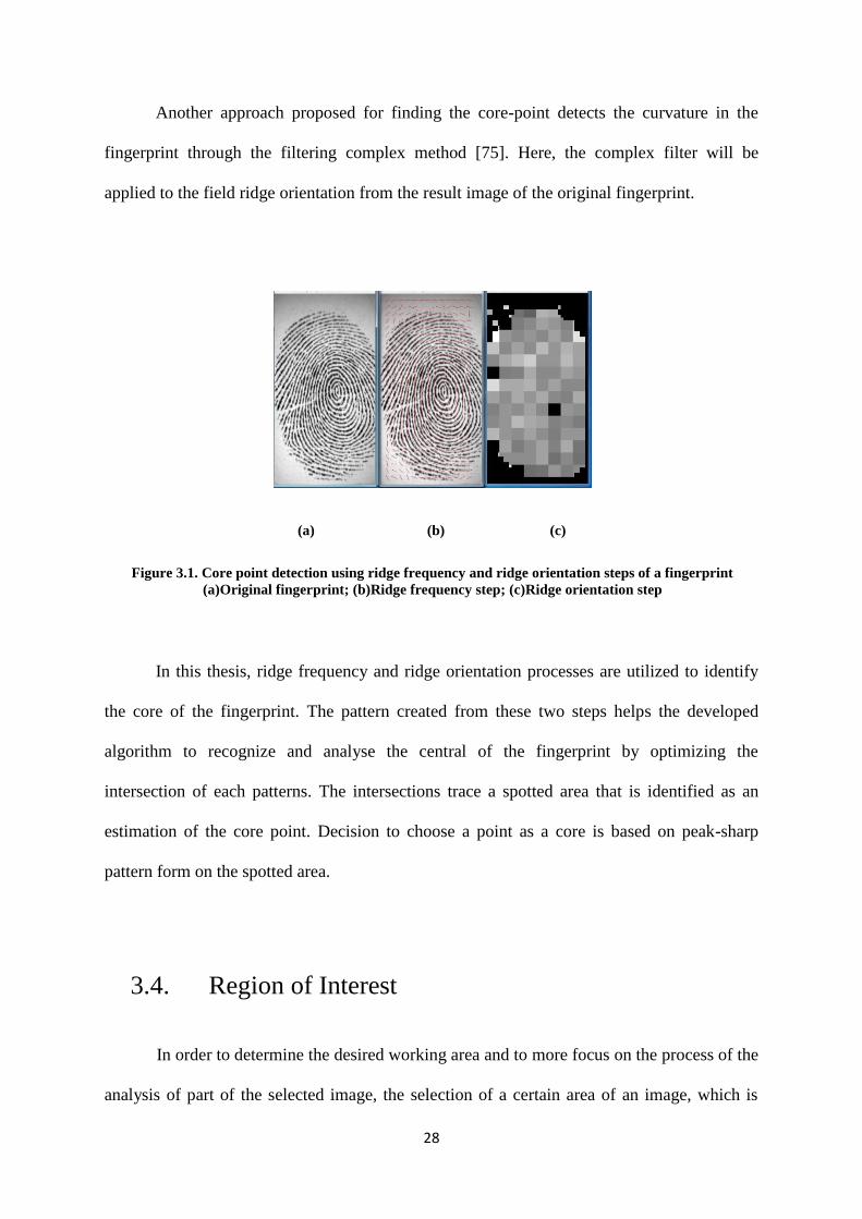
Another approach proposed for finding the core-point detects the curvature in the
fingerprint through the filtering complex method [75]. Here, the complex filter will be
applied to the field ridge orientation from the result image of the original fingerprint.
(a) (b) (c)
Figure 3.1. Core point detection using ridge frequency and ridge orientation steps of a fingerprint
(a)Original fingerprint; (b)Ridge frequency step; (c)Ridge orientation step
In this thesis, ridge frequency and ridge orientation processes are utilized to identify
the core of the fingerprint. The pattern created from these two steps helps the developed
algorithm to recognize and analyse the central of the fingerprint by optimizing the
intersection of each patterns. The intersections trace a spotted area that is identified as an
estimation of the core point. Decision to choose a point as a core is based on peak-sharp
pattern form on the spotted area.
3.4. Region of Interest
In order to determine the desired working area and to more focus on the process of the
analysis of part of the selected image, the selection of a certain area of an image, which is
29
also known as the region of interest (RoI), is also required. This stage of image processing
can combine, extract, remove and transform the area resulting from the selection process into
an image window. In biometrics, this selection process is needed to select numerous
biometric characteristics that are accurate and contain less noise objects. For example, a
fingerprint is normally obtained as a result of scaning process. This means that the fingerprint
not only contains the information but is also surrounded by noise that becomes the
background of the fingerprint.
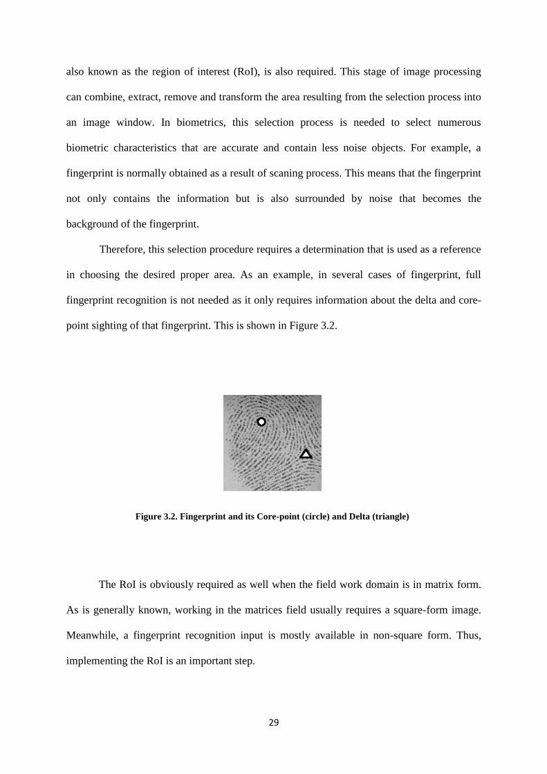
Therefore, this selection procedure requires a determination that is used as a reference
in choosing the desired proper area. As an example, in several cases of fingerprint, full
fingerprint recognition is not needed as it only requires information about the delta and core-
point sighting of that fingerprint. This is shown in Figure 3.2.
Figure 3.2. Fingerprint and its Core-point (circle) and Delta (triangle)
The RoI is obviously required as well when the field work domain is in matrix form.
As is generally known, working in the matrices field usually requires a square-form image.
Meanwhile, a fingerprint recognition input is mostly available in non-square form. Thus,
implementing the RoI is an important step.
30
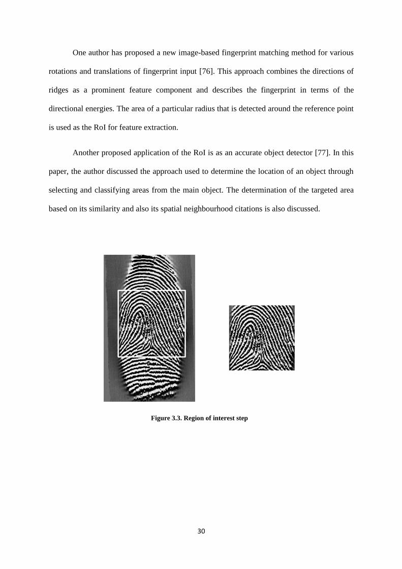
One author has proposed a new image-based fingerprint matching method for various
rotations and translations of fingerprint input [76]. This approach combines the directions of
ridges as a prominent feature component and describes the fingerprint in terms of the
directional energies. The area of a particular radius that is detected around the reference point
is used as the RoI for feature extraction.
Another proposed application of the RoI is as an accurate object detector [77]. In this
paper, the author discussed the approach used to determine the location of an object through
selecting and classifying areas from the main object. The determination of the targeted area
based on its similarity and also its spatial neighbourhood citations is also discussed.
Figure 3.3. Region of interest step
31
3.5. Fingerprint Classification
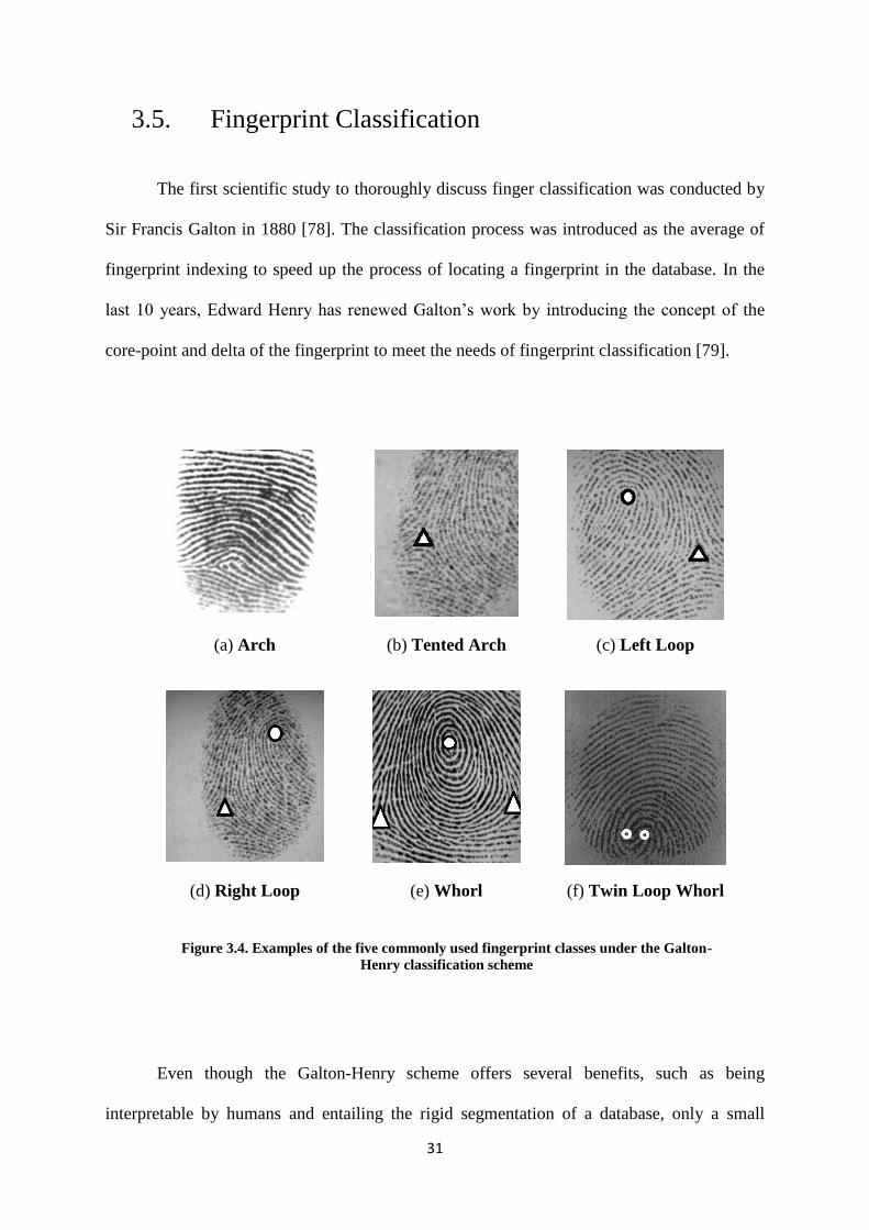
The first scientific study to thoroughly discuss finger classification was conducted by
Sir Francis Galton in 1880 [78]. The classification process was introduced as the average of
fingerprint indexing to speed up the process of locating a fingerprint in the database. In the
last 10 years, Edward Henry has renewed Galton’s work by introducing the concept of the
core-point and delta of the fingerprint to meet the needs of fingerprint classification [79].
(a) Arch (b) Tented Arch (c) Left Loop
(d) Right Loop (e) Whorl (f) Twin Loop Whorl
Figure 3.4. Examples of the five commonly used fingerprint classes under the Galton-
Henry classification scheme
Even though the Galton-Henry scheme offers several benefits, such as being
interpretable by humans and entailing the rigid segmentation of a database, only a small

32
number of classes can be automatically applied to the system. As an example, most of the
automatic systems [80], [50], [81], [82], [83] can only classify fingerprints into six classes as
shown in Figure 3.4.
Conversely, there are many fingerprints that cannot be easily distributed into classes
and which cannot even be classified properly by an expert because of the ambiguity of the
fingerprint features. Therefore, the Galton-Henry scheme that separates a fingerprint database
into interpretable classes for humans will not be free from error. Moreover, this scheme does
not offer fingerprint selectivity for a larger database. In fact, it is unnecessary for the
automatic system to sort the database into fingerprint classes that can be interpreted by
humans.
In the Automatic Fingerprint Identification System (AFIS), the purpose of the
classification process is to reduce the area that needs to be searched. This purpose can be
achieved by sorting the database into fingerprint machine-generated classes in the feature
area, as long as the search is consistent and reliable. For example, some indexing fingerprint
techniques [84], [85] can clear up the search area more efficiently than the scheme used by
Galton-Henry.
The classification techniques that are regularly being proposed [19], [86], [87] do not
classify the database in the beginning, but represent each fingerprint with a numerical feature
vector. Moreover, it gives a query fingerprint where a class is formed by regaining part of the
fingerprint that has feature vectors in the database, in which the database has the proximity
value with the query fingerprint. Although these techniques can classify fingerprints into a
number of fingerprint classes, a query fingerprint is still required to be compared with all the
fingerprints in the database, which can be time consuming for larger databases. This issue can
33
be prevented by using a technique combining groups of data in the fingerprint retrieval
framework [87], [88].
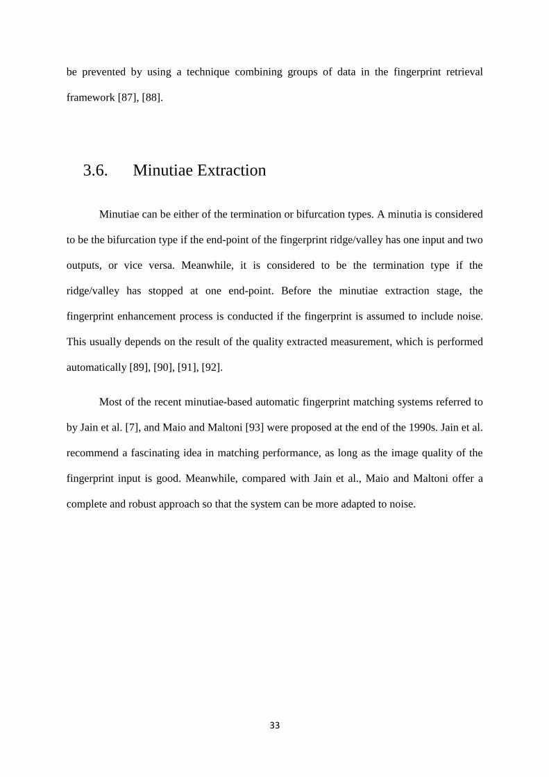
3.6. Minutiae Extraction
Minutiae can be either of the termination or bifurcation types. A minutia is considered
to be the bifurcation type if the end-point of the fingerprint ridge/valley has one input and two
outputs, or vice versa. Meanwhile, it is considered to be the termination type if the
ridge/valley has stopped at one end-point. Before the minutiae extraction stage, the
fingerprint enhancement process is conducted if the fingerprint is assumed to include noise.
This usually depends on the result of the quality extracted measurement, which is performed
automatically [89], [90], [91], [92].
Most of the recent minutiae-based automatic fingerprint matching systems referred to
by Jain et al. [7], and Maio and Maltoni [93] were proposed at the end of the 1990s. Jain et al.
recommend a fascinating idea in matching performance, as long as the image quality of the
fingerprint input is good. Meanwhile, compared with Jain et al., Maio and Maltoni offer a
complete and robust approach so that the system can be more adapted to noise.
34
Figure 3.5. Examples of the minutiae extraction of two different fingerprint database sources (FVC 2002
and BRC)
3.7. Summary
In this chapter, the first subject discussed concerned the production of a dependable
cancellable fingerprint that requires a fingerprint input with improved quality, so as to ensure
that no feature information is missing from the fingerprint. That is why for most fingerprint
image processes, including generating a cancellable fingerprint using matrices operations,
two stages important in order to ensure success are image enhancement, such as by
normalization, binarization, or quality mark-up and feature extraction such as by minutiae
extraction, core-point identification, or pore extraction.
However, the performance of a fingerprint feature extraction and matching algorithm
heavily depends upon the quality of the input of the fingerprint image. In reality, fingerprint

35
images are rarely of perfect quality. Given that the quality of a fingerprint image is not able to
be measured objectively, it roughly corresponds to the clarity of the ridge structure in the
fingerprint image. It can be judged as a qualifying image when it has well-defined ridges and
valleys, and is of high contrast. Images may be degraded and corrupted with an element of
noise due to many factors, including variations in skin and impression conditions.
Because a biometric property is an intrinsic trait of an individual, it is difficult to
confidentially duplicate and virtually impossible to share. Moreover, the biometric properties
of an individual can only be lost in the case of a serious accident. Even though automated
biometrics can help alleviate the problems associated with the existing methods of user
authentication, an assailant might still be able to locate several weak points in the system,
making it vulnerable to attack. The problems with biometric authentication systems occurs
when the data associated with a biometric feature has been compromised.
In the next chapter, a novel methodology to generate a cancellable biometric is
discussed in detail. The relevant methodology is introduced in term of generating a
cancellable fingerprint feature.

36
Chapter 4
4. Matrix Operations and Cancellable Fingerprint
4.1. Introduction
The main aim in generating cancellable biometrics is the production of a reliable
revocable biometric template. A cancellable biometric is needed to protect an authorized
persons information from an impostor. One way of doing this is by randomizing the original
biometric feature to generate a vague image. In this thesis, the disguising process is achieved
using three matrices operations: the elementary row operations (ERO), the Kronecker product
(KP) operation and an inverse matrix operation.
This idea is to deliver one of the cancellable biometric approaches, because using
ERO, KP, and inverse operations can allow several alternatives in randomizing the original
image as long as it is able to satisfy the three requirements of non-invertible matrices:
1. At least one row or column of the original matrix should be of zero (0) value.
2. The original matrix must be modified into a non-square matrix form.
3. It must be ensured that none of the rows is a multiple of another row.
Meanwhile, the Kronecker/tensor product is used to provide a large, non-invertible
and totally different cancellable biometric image when compared with the original biometric
image.

37
4.2. Basic Idea of Generating Cancellable Features
A feature can be categorized as cancellable when it is non-invertible to the original
image. The same thing applies to matrices. The matrix cannot be inverted when satisfying
three situations:
1. There is one zero row at least.
2. There is a row that is a multiple of another row.
3. The matrix form is not a square.
The first requirement can be achieved using the elementary row operation (ERO),
where a selected row is multiplied by zero. Meanwhile, for the next requirement, given that it
is rare to find a row in an image system which is a multiple of another row, this can be
created by using ERO. Furthermore, to ensure that the obtained cancellable matrix is
completely masked and to be able to meet the last requirement for the non-invertible matrix,
in this research each element of the transformed matrix is multiplied by an arbitrary
matrix/element. This process is called the Kronecker product or tensor product operation. By
using this process, the outcome is that both matrices have numerous elements and an
adjustable matrix form (whether a rectangular or square matrix).
As matrices are used in this field, then there should be no noise at all because the
existence of noise may add specific information to the biometric feature. The noise on the
fingerprint can be occurred when the surface of the scanner in the acquisition process is
unclear. This is relevant for a cancellable biometric, since the final stage of this system is the
authentication process and even a small amount of noise will significantly affect the quality
of the cancellable feature and will certainly result in low precision during the verification
38
process later on. Thus, the early process to be undertaken towards the result of the established
fingerprint is an enhancement step. The enhanced fingerprint will provide a feature with the
precise value of fingerprint information so that when it is extracted to domain matrices, no
unnecessary values will go into it. After following several fingerprint steps, the cancellable
input image will be produced by several matrices operations.
In view of the fact that it is already in a matrix domain, then the next issue to be
discussed is how to build the cancellable biometrics system using an input matrix A. Firstly,
matrix A will be inverted as the first step in disguising the real feature. This idea is an initial
step, as it will be considered whether directly inversing matrix A is effective or, conversely,
inversing matrix A after another matrix operation. The next step will be to determine whether
to apply the rlementary row operation (ERO) to matrix A to obtain a zero-value row or to
apply the Kronecker Product (KP) operation. It is also necessary to determine how many zero
rows are required to achieve the required maximum non-invertible matrix. Besides the use of
ERO to obtain zero rows, another method to be considered in this research is the use of ERO
to create rows that are the multiples of other rows.
After implementing the ERO operation with matrix A, the result of this operation can
be named matrix K. This will then go through a KP operation to produce a KP matrix, where
every initial element is unrecognizable. Let us name this matrix M. In this KP operation,
matrix K will be multiplied by a tensor factor that can be in the form of a matrix or integer
with a constant value called B. The form and value of factor B will be further investigated in
this research. For example, if factor B is a matrix, then the value can be taken from the
numbers given by a person who has registered his biometrics when registering as an authentic
person for a biometric whose cancellable feature is being created. In this research, the steps
using ERO and KP will be analysed as well, including whether the use of ERO in the
beginning and KP afterwards is better, or vice versa. The result of this process will be a

39
cancellable matrix of matrix A, which will be seen specifically as matrix C which is a
cancellable template.
4.3. Matrix Implementation
The above processes can be illustrated using the following mathematical steps. It can
be noted that the original input matrix A is a three-by-three matrix. The first alternative step
that is used is to invert the original matrix, so as to disguise it.
A-1
=1
|A|adjA (4.1)
Supposing A = [2 5 7
3 2 0
8 9 6
], (4.2)
where |A|=11, and
adjA= [
12 33 11
-18 -44 21
11 22 -11
], (4.3)
so that,
A-1
=
[
12
113 -
14
11
-18
11-4
21
11
1 2 -1 ]
, (4.4)

40
To obtain the Kronecker product (KP), another matrix should be determined. In order
to provide more of an overview, there are two alternatives for that matrix; firstly, a non-
square form matrix B observed as in the matrix below
B= [11 11
0 0
11 11
]. (4.5)
The reasons for establishing this matrix are firstly to show why a non-square matrix
cannot be inverted; and secondly, why if there is at least one zero row, the matrix cannot be
inverted as well. Furthermore, A-1⨂B=
[
12
113 -
14
11
-18
11-4
21
11
1 2 -1 ]
⨂ [11 11
0 0
11 11
]=
KP =
[ 12 12
0 0
12 12
33 33
0 0
33 33
-14 -14
0 0
-14 -14
-18 -18
0 0
-18 -18
-44 -44
0 0
-44 -44
21 21
0 0
21 21
11 11
0 0
11 11
22 22
0 0
22 22
-11 -11
0 0
-11 -11]
; (4.6)
where KP matrix is a 9 x 6 form (non-square matrix).
A matrix can be said to have an inverse if A.A-1
= I; where I is a matrix identity.
Meanwhile, a matrix is able to be a matrix identity if the diagonal elements of the matrix are
1 (one), whereas the other elements are 0 (zero). Based on this requirement, the matrix

41
identity should be a square form matrix. Since 9 by 6 is not a square form matrix, this proves
that the KP matrix does not have an inverse.
The next alternative is a non-square form matrix B observed as the matrix below:
B= [11 11 11
0 0 0
11 11 11
]. (4.7)
That, A-1⨂B=KP=
[
12
113 -
14
11
-18
11-4
21
11
1 2 -1 ]
⨂ [11 11 11
0 0 0
11 11 11
]
KP =
[ 12 12 12
0 0 0
12 12 12
33 33 33
0 0 0
33 33 33
-14 -14 -14
0 0 0
-14 -14 -14
-18 -18 -18
0 0 0
-18 -18 -18
-44 -44 -44
0 0 0
-44 -44 -44
21 21 21
0 0 0
21 21 21
11 11 11
0 0 0
11 11 11
22 22 22
0 0 0
22 22 22
-11 -11 -11
0 0 0
-11 -11 -11]
(4.8)
Currently, the form of the matrix KP is square (9 by 9). This 9 by 9 matrix can be
inverted when KP.KP-1
= I. In this case, the matrix identity can be symbolized as matrix C
and the KP-1
as matrix P: where,

42
C =
[ C11 C12 C13
C21 C22 C23
C31 C32 C33
C14 C15 C16
C24 C25 C26
C34 C35 C36
C17 C18 C19
C27 C28 C29
C37 C38 C39
C41 C42 C43
C51 C52 C53
C61 C62 C63
C44 C45 C46
C54 C55 C56
C64 C65 C66
C47 C48 C49
C57 C58 C59
C67 C68 C69
C71 C72 C73
C81 C82 C83
C91 C92 C93
C74 C75 C76
C84 C85 C86
C94 C95 C96
C77 C78 C79
C87 C88 C89
C97 C98 C99]
=
[ 1 0 0 0 0 0 0 0 0
0 1 0 0 0 0 0 0 0
0 0 1 0 0 0 0 0 0
0 0 0 1 0 0 0 0 0
0 0 0 0 1 0 0 0 0
0 0 0 0 0 1 0 0 0
0 0 0 0 0 0 1 0 0
0 0 0 0 0 0 0 1 0
0 0 0 0 0 0 0 0 1]
; (4.9)
From the matrix above, it is clear that the diagonal elements of C should be 1 and the others
0.
The computation can be simplified by firstly checking the diagonal elements of
KPxKP-1
or KP x P (C11, C22, C33, C44, C55, C66, C77, C88, C99); where,
C11 = (12xP11) + (12xP21) + (12xP31) + (33xP41) + (33xP51) + (33xP61) + (-14xP71) +
(-14xP81) +
(-14xP91) (4.10)
C22 = (0xP12) + (0xP22) + (0xP32) + (0xP42) + (0xP52) + (0xP62) + (0xP72) + (0xP82) +
(0xP92)
= 0 ===> this means that C ≠ I ( matrix C is not equal to matrix identity); (4.11)

43
In summary, it can be said that matrix KP is a non-invertible matrix.
Referring to the explanation in the two previous sub sections above, it is obvious that
matrix operations such as the elementary row operation (ERO) and Kronecker product
operation (KR) can be implemented to generate a cancellable biometric. This is based on a
similar approach between a cancellable biometric and a non-inverted matrix. In the former
field, a cancellable method can be said to be successful when the yield image is not able to be
retransformed into the original image. The same goes for the latter field. In the matrix
domain, if the goal is to obtain a revocable matrix, then the non-inverse matrix requirement
should be fulfilled to make the matrix non-invertible.
4.4. Algorithm Outline
A feature can be categorized as a cancellable feature when it is non-invertible to the
In this novel research, the first step to be achieved is to prove that implementing several
matrix operations to produce a revocable biometric image can be used as a novel approach in
the cancellablity field. Therefore, in this research step, pre-processing steps have thus far not
been discussed.
Nevertheless, a good quality input image is obviously required, as the work will be
undertaken in a matrix domain. Consequently, a recent method related to this issue
isdiscussed in the next chapter of this thesis. Generally, the outline of this proposed research
is as shown in Figure 4.1. whereas the input of cancellable is the result of all of the
fingerprint pre-processing steps used in this research.
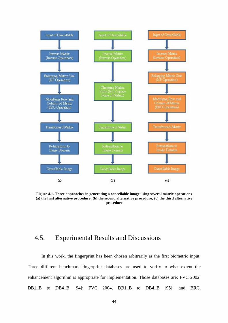
44
Figure 4.1. Three approaches in generating a cancellable image using several matrix operations
(a) the first alternative procedure; (b) the second alternative procedure; (c) the third alternative
procedure
4.5. Experimental Results and Discussions
In this work, the fingerprint has been chosen arbitrarily as the first biometric input.
Three different benchmark fingerprint databases are used to verify to what extent the
enhancement algorithm is appropriate for implementation. Those databases are: FVC 2002,
DB1_B to DB4_B [94]; FVC 2004, DB1_B to DB4_B [95]; and BRC,
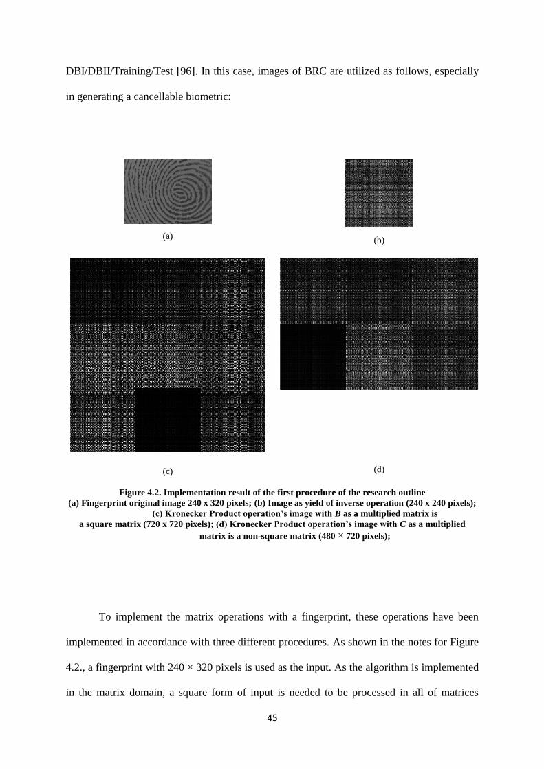
45
DBI/DBII/Training/Test [96]. In this case, images of BRC are utilized as follows, especially
in generating a cancellable biometric:
(a)
(b)
(c)
(d)
Figure 4.2. Implementation result of the first procedure of the research outline
(a) Fingerprint original image 240 x 320 pixels; (b) Image as yield of inverse operation (240 x 240 pixels);
(c) Kronecker Product operation’s image with B as a multiplied matrix is
a square matrix (720 x 720 pixels); (d) Kronecker Product operation’s image with C as a multiplied
matrix is a non-square matrix (480 × 720 pixels);
To implement the matrix operations with a fingerprint, these operations have been
implemented in accordance with three different procedures. As shown in the notes for Figure
4.2., a fingerprint with 240 × 320 pixels is used as the input. As the algorithm is implemented
in the matrix domain, a square form of input is needed to be processed in all of matrices
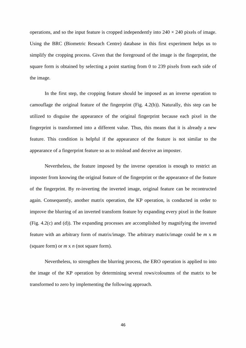
46
operations, and so the input feature is cropped independently into 240 × 240 pixels of image.
Using the BRC (Biometric Reseach Centre) database in this first experiment helps us to
simplify the cropping process. Given that the foreground of the image is the fingerprint, the
square form is obtained by selecting a point starting from 0 to 239 pixels from each side of
the image.
In the first step, the cropping feature should be imposed as an inverse operation to
camouflage the original feature of the fingerprint (Fig. 4.2(b)). Naturally, this step can be
utilized to disguise the appearance of the original fingerprint because each pixel in the
fingerprint is transformed into a different value. Thus, this means that it is already a new
feature. This condition is helpful if the appearance of the feature is not similar to the
appearance of a fingerprint feature so as to mislead and deceive an imposter.
Nevertheless, the feature imposed by the inverse operation is enough to restrict an
imposter from knowing the original feature of the fingerprint or the appearance of the feature
of the fingerprint. By re-inverting the inverted image, original feature can be recontructed
again. Consequently, another matrix operation, the KP operation, is conducted in order to
improve the blurring of an inverted transform feature by expanding every pixel in the feature
(Fig. 4.2(c) and (d)). The expanding processes are accomplished by magnifying the inverted
feature with an arbitrary form of matrix/image. The arbitrary matrix/image could be m x m
(square form) or m x n (not square form).
Nevertheless, to strengthen the blurring process, the ERO operation is applied to into
the image of the KP operation by determining several rows/coloumns of the matrix to be
transformed to zero by implementing the following approach.

47
𝑓(𝐴) = 𝑚𝐴 + 𝑛𝐶, 𝐴 = 1,… ,𝑚 if 𝑚 < 𝑛 and 𝐴 = 1,… , 𝑛 if 𝑚 > 𝑛; 𝐶 ∈ ℝ; (4.12)
where : f(A) is the row which becomes zero,
A is the selected row,
m and n are a row and coloum.
The above equation helps to determine which row the ERO is applied to and restrains
this matrix operation due to the excessive number of zero rows. Basically, the ERO’s yield
feature is quite similar to the KP’s feature, although it is different in value. This similarity
helps to divert an imposter if they try to invert a cancellable feature to detect the original
version of the fingerprint. In this step, the ERO yields a cancellable fingerprint feature
(Figure 4.3).
Figure 4.3. Image as a result of elementary row operation (the cancellable fingerprint image)
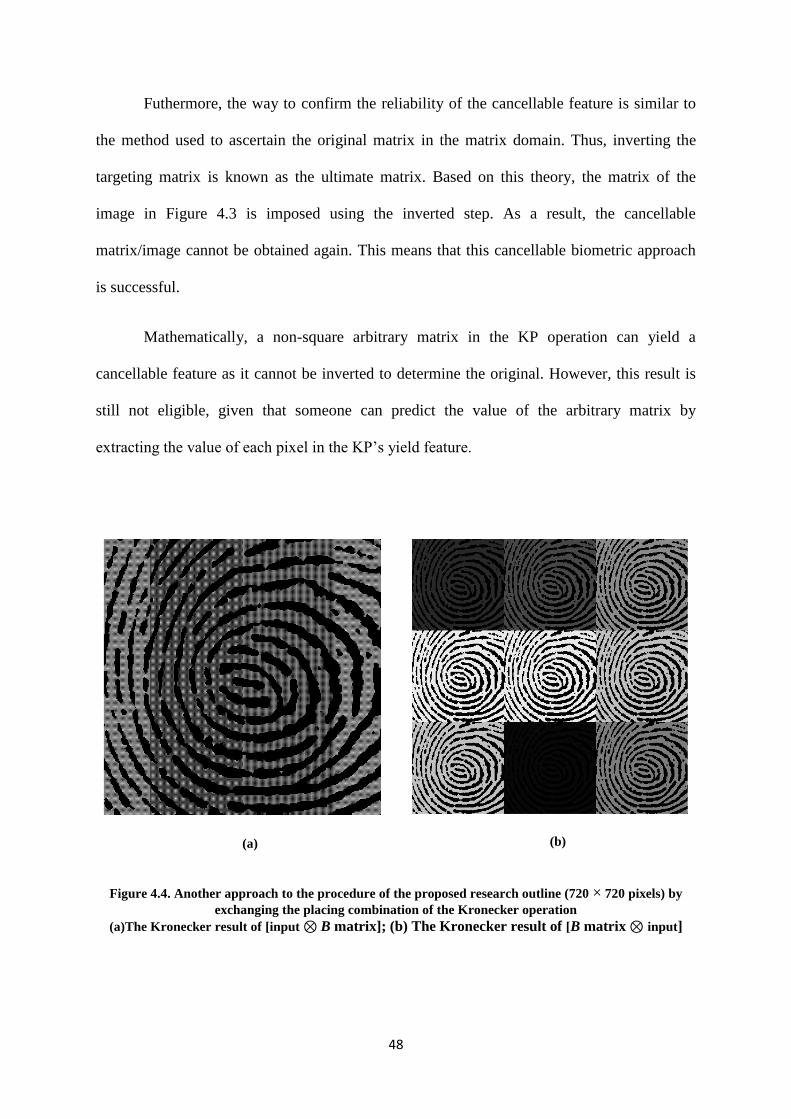
48
Futhermore, the way to confirm the reliability of the cancellable feature is similar to
the method used to ascertain the original matrix in the matrix domain. Thus, inverting the
targeting matrix is known as the ultimate matrix. Based on this theory, the matrix of the
image in Figure 4.3 is imposed using the inverted step. As a result, the cancellable
matrix/image cannot be obtained again. This means that this cancellable biometric approach
is successful.
Mathematically, a non-square arbitrary matrix in the KP operation can yield a
cancellable feature as it cannot be inverted to determine the original. However, this result is
still not eligible, given that someone can predict the value of the arbitrary matrix by
extracting the value of each pixel in the KP’s yield feature.
(a)
(b)
Figure 4.4. Another approach to the procedure of the proposed research outline (720 × 720 pixels) by
exchanging the placing combination of the Kronecker operation
(a)The Kronecker result of [input ⊗ B matrix]; (b) The Kronecker result of [B matrix ⊗ input]
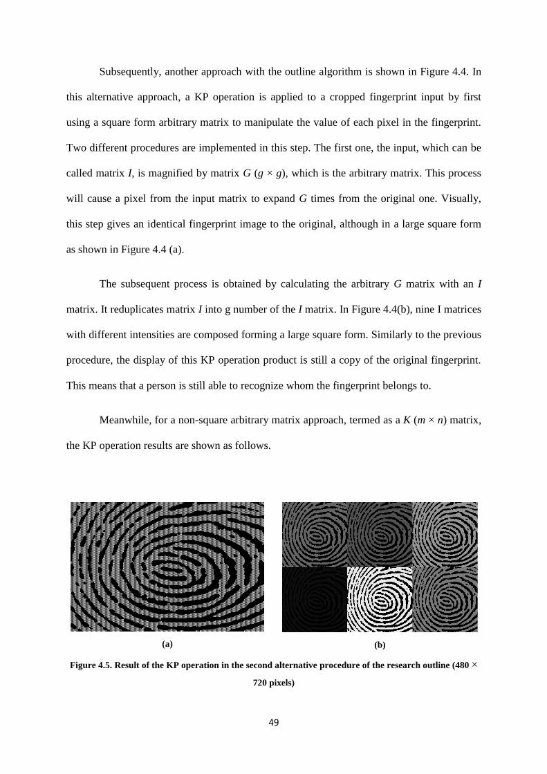
49
Subsequently, another approach with the outline algorithm is shown in Figure 4.4. In
this alternative approach, a KP operation is applied to a cropped fingerprint input by first
using a square form arbitrary matrix to manipulate the value of each pixel in the fingerprint.
Two different procedures are implemented in this step. The first one, the input, which can be
called matrix I, is magnified by matrix G (g × g), which is the arbitrary matrix. This process
will cause a pixel from the input matrix to expand G times from the original one. Visually,
this step gives an identical fingerprint image to the original, although in a large square form
as shown in Figure 4.4 (a).
The subsequent process is obtained by calculating the arbitrary G matrix with an I
matrix. It reduplicates matrix I into g number of the I matrix. In Figure 4.4(b), nine I matrices
with different intensities are composed forming a large square form. Similarly to the previous
procedure, the display of this KP operation product is still a copy of the original fingerprint.
This means that a person is still able to recognize whom the fingerprint belongs to.
Meanwhile, for a non-square arbitrary matrix approach, termed as a K (m × n) matrix,
the KP operation results are shown as follows.
(a)
(b)
Figure 4.5. Result of the KP operation in the second alternative procedure of the research outline (480 ×
720 pixels)
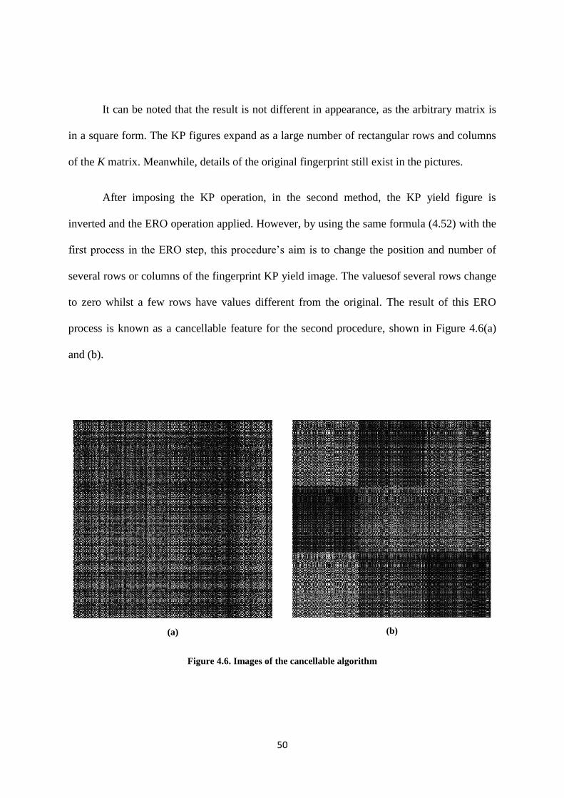
50
It can be noted that the result is not different in appearance, as the arbitrary matrix is
in a square form. The KP figures expand as a large number of rectangular rows and columns
of the K matrix. Meanwhile, details of the original fingerprint still exist in the pictures.
After imposing the KP operation, in the second method, the KP yield figure is
inverted and the ERO operation applied. However, by using the same formula (4.52) with the
first process in the ERO step, this procedure’s aim is to change the position and number of
several rows or columns of the fingerprint KP yield image. The valuesof several rows change
to zero whilst a few rows have values different from the original. The result of this ERO
process is known as a cancellable feature for the second procedure, shown in Figure 4.6(a)
and (b).
(a)
(b)
Figure 4.6. Images of the cancellable algorithm
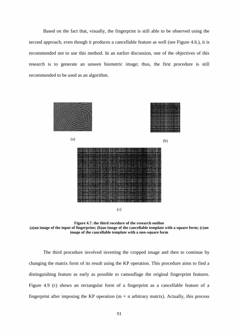
51
Based on the fact that, visually, the fingerprint is still able to be observed using the
second approach, even though it produces a cancellable feature as well (see Figure 4.6.), it is
recommended not to use this method. In an earlier discussion, one of the objectives of this
research is to generate an unseen biometric image; thus, the first procedure is still
recommended to be used as an algorithm.
(a)
(b)
(c)
Figure 4.7. the third rocedure of the research outline
(a)an image of the input of fingerprint; (b)an image of the cancellable template with a square form; (c)an
image of the cancellable template with a non-square form
The third procedure involved inverting the cropped image and then to continue by
changing the matrix form of its result using the KP operation. This procedure aims to find a
distinguishing feature as early as possible to camouflage the original fingerprint features.
Figure 4.9 (c) shows an rectangular form of a fingerprint as a cancellable feature of a
fingerprint after imposing the KP operation (m × n arbitrary matrix). Actually, this process

52
has a benefit in terms of time complexity since it undergoes no ERO step, wherein the latter
step sometimes consumes 30 to 40% of all the required time to generate the cancellable
fingerprint. However, this step has a disadvantage, especially if the arbitrary matrix in the
process is identified by an imposter.
4.6. Summary
In this chapter, it is noted that the proposeed approach can be relied upon to generate
a cancellable template. It can be said that if the information data of the input of the fingerprint
is not similar to the cancellable template, the proposed cancellable template is irrevocable. In
fact, there are three procedures that can be used to produce it: firstly, by inverting-enlarging-
rotating the image matrix as can be observed in Figure.4.8.
Figure 4.8. Illustration flow of the first procedure of the research outline
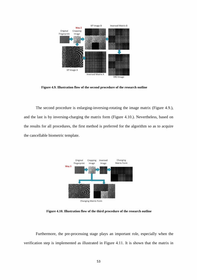
53
Figure 4.9. Illustration flow of the second procedure of the research outline
The second procedure is enlarging-inversing-rotating the image matrix (Figure 4.9.),
and the last is by inversing-charging the matrix form (Figure 4.10.). Nevertheless, based on
the results for all procedures, the first method is preferred for the algorithm so as to acquire
the cancellable biometric template.
Figure 4.10. Illustration flow of the third procedure of the research outline
Furthermore, the pre-processing stage plays an important role, especially when the
verification step is implemented as illustrated in Figure 4.11. It is shown that the matrix in

54
Fig.4.11(a), which is a matrix with an enhanced process, has a different information data
compared to the matrix in Fig.4.11(b) which is using B pre-processing algorithm.
(a) (b)
Figure 4.11. Illustration of the Importance of Pre-Processing Step for Fingerprint.
Deviation value occurs (red square): (a) The pre-processing matrix of an A pre-processing
algorithm; (b) The pre-processing matrix of an B pre-processing algorithm
At the moment, there is an element of matrix in the original image, as a result of a pre
processing step that does not have value as to what it is; therefore, the image will be rejected
in the verification process. This is because in this procedure, each of the element values
describe what the image is, no matter what.
1 1 0 0 0 1
0 0 1 1 1 0
1 1 1 1 1 1
1 1 0 0 0 0
0 0 1 1 0 1
0 0 1 0 1 1
1 1 0 0 0 1
0 0 1 1 1 0
1 1 1 1 1 1
1 1 0 1 0 0
0 0 1 1 0 1
0 0 1 0 1 1
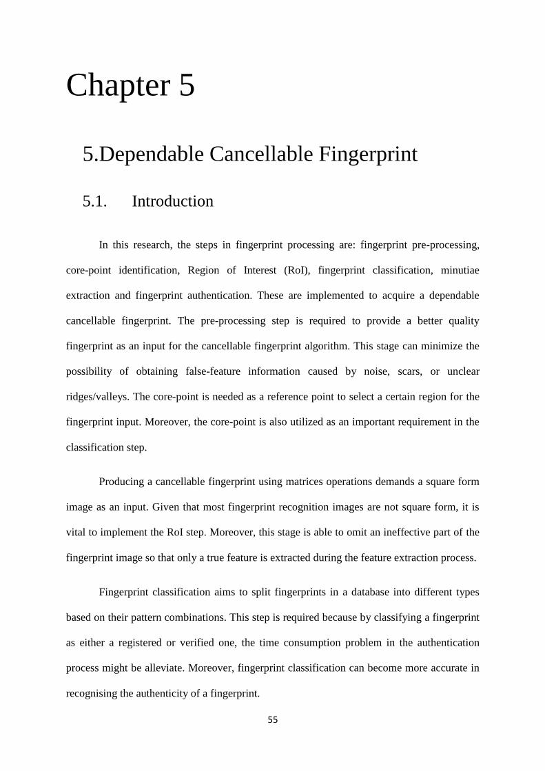
55
Chapter 5
5.Dependable Cancellable Fingerprint
5.1. Introduction
In this research, the steps in fingerprint processing are: fingerprint pre-processing,
core-point identification, Region of Interest (RoI), fingerprint classification, minutiae
extraction and fingerprint authentication. These are implemented to acquire a dependable
cancellable fingerprint. The pre-processing step is required to provide a better quality
fingerprint as an input for the cancellable fingerprint algorithm. This stage can minimize the
possibility of obtaining false-feature information caused by noise, scars, or unclear
ridges/valleys. The core-point is needed as a reference point to select a certain region for the
fingerprint input. Moreover, the core-point is also utilized as an important requirement in the
classification step.
Producing a cancellable fingerprint using matrices operations demands a square form
image as an input. Given that most fingerprint recognition images are not square form, it is
vital to implement the RoI step. Moreover, this stage is able to omit an ineffective part of the
fingerprint image so that only a true feature is extracted during the feature extraction process.
Fingerprint classification aims to split fingerprints in a database into different types
based on their pattern combinations. This step is required because by classifying a fingerprint
as either a registered or verified one, the time consumption problem in the authentication
process might be alleviate. Moreover, fingerprint classification can become more accurate in
recognising the authenticity of a fingerprint.

56
Nevertheless, the possibility of establishing a cancellable fingerprint by using an
enhanced fingerprint image such as by minutiae extraction needs to be determined as well.
The reason for this is that minutiae are not visible to the naked eye and appear as a scattered
set of points. However, implementing an improved minutiae extraction approach is required
to omit false recorded information for fingerprint recognition.
Furthermore, the performance of a fingerprint feature extraction and matching
algorithm depends heavily upon the quality of the input image. In reality, fingerprint images
are rarely of good quality. As the quality of a fingerprint image cannot be measured
objectively, it roughly corresponds to the clarity of the ridge structure in the fingerprint
image. An image can be judged as qualifying image when it has well-defined ridges and
valleys and high contrast. However, images may be degraded and corrupted with elements of
noise due to many factors including variations in skin and impression conditions.
5.2. Fingerprint Enhancement
The aim of fingerprint image enhancement is to improve the quality of fingerprint
input to make further operations easier. If it is presumed that the fingerprint images acquired
from sensors or other media are not of sufficient quality to increase the contrast between the
ridges and furrows and to connect falsely broken points of the ridges due to noise caused by
the use of ink, enhancement methods are helpful in maintaining superior accuracy in
fingerprint recognition.
In this research, although a novel fingerprint enhancement technique is not required,
this general step is needed to compare the results from a cancellable fingerprint with and
without an enhancement step. Nevertheless, several methods have been proposed for
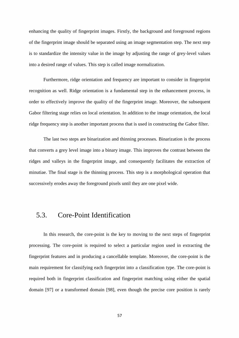
57
enhancing the quality of fingerprint images. Firstly, the background and foreground regions
of the fingerprint image should be separated using an image segmentation step. The next step
is to standardize the intensity value in the image by adjusting the range of grey-level values
into a desired range of values. This step is called image normalization.
Furthermore, ridge orientation and frequency are important to consider in fingerprint
recognition as well. Ridge orientation is a fundamental step in the enhancement process, in
order to effectively improve the quality of the fingerprint image. Moreover, the subsequent
Gabor filtering stage relies on local orientation. In addition to the image orientation, the local
ridge frequency step is another important process that is used in constructing the Gabor filter.
The last two steps are binarization and thinning processes. Binarization is the process
that converts a grey level image into a binary image. This improves the contrast between the
ridges and valleys in the fingerprint image, and consequently facilitates the extraction of
minutiae. The final stage is the thinning process. This step is a morphological operation that
successively erodes away the foreground pixels until they are one pixel wide.
5.3. Core-Point Identification
In this research, the core-point is the key to moving to the next steps of fingerprint
processing. The core-point is required to select a particular region used in extracting the
fingerprint features and in producing a cancellable template. Moreover, the core-point is the
main requirement for classifying each fingerprint into a classification type. The core-point is
required both in fingerprint classification and fingerprint matching using either the spatial
domain [97] or a transformed domain [98], even though the precise core position is rarely
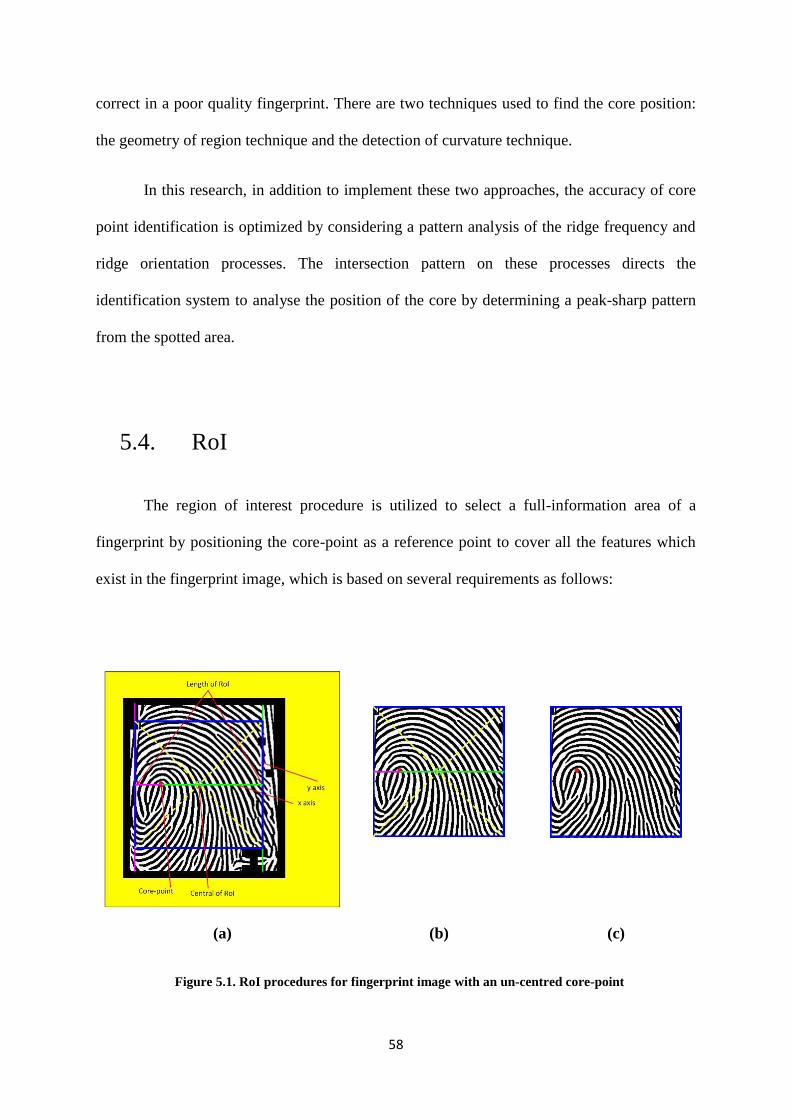
58
correct in a poor quality fingerprint. There are two techniques used to find the core position:
the geometry of region technique and the detection of curvature technique.
In this research, in addition to implement these two approaches, the accuracy of core
point identification is optimized by considering a pattern analysis of the ridge frequency and
ridge orientation processes. The intersection pattern on these processes directs the
identification system to analyse the position of the core by determining a peak-sharp pattern
from the spotted area.
5.4. RoI
The region of interest procedure is utilized to select a full-information area of a
fingerprint by positioning the core-point as a reference point to cover all the features which
exist in the fingerprint image, which is based on several requirements as follows:
(a) (b) (c)
Figure 5.1. RoI procedures for fingerprint image with an un-centred core-point
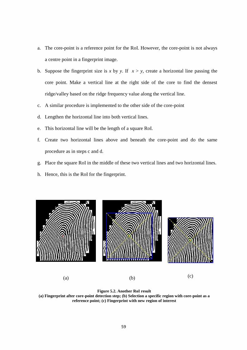
59
a. The core-point is a reference point for the RoI. However, the core-point is not always
a centre point in a fingerprint image.
b. Suppose the fingerprint size is x by y. If x > y, create a horizontal line passing the
core point. Make a vertical line at the right side of the core to find the densest
ridge/valley based on the ridge frequency value along the vertical line.
c. A similar procedure is implemented to the other side of the core-point
d. Lengthen the horizontal line into both vertical lines.
e. This horizontal line will be the length of a square RoI.
f. Create two horizontal lines above and beneath the core-point and do the same
procedure as in steps c and d.
g. Place the square RoI in the middle of these two vertical lines and two horizontal lines.
h. Hence, this is the RoI for the fingerprint.
(a) (b) (c)
Figure 5.2. Another RoI result
(a) Fingerprint after core-point detection step; (b) Selection a specific region with core-point as a
reference point; (c) Fingerprint with new region of interest
60
5.5. Fingerprint Classification
Fingerprint classification is needed to decrease time consumption in the authentication
step. In the authentication process, a query fingerprint will be checked by comparing it with
all the fingerprints in the database. If the database is very large, this step can become a
“bottleneck” in terms of speed. This would not be acceptable in a busy online application
such as a bank, an office, and in terms of security. Therefore, the classification step assists
systems to reduce the number of fingerprints that need to be authenticated.
The unusual distribution of fingerprint classes based on human interpretation will then
decrease the efficiency of the fingerprint classification process. Instead of combining the
fingerprint based on its visual appearance to generate more classes, such as tented, arc tented,
right loop, left loop, and whorl; a classification scheme will be consistently distributed to the
same classes. This scheme can basically be implemented in the long term, as a result of
different impressions from the same fingerprint. However, there are fingerprints that always
can be separated without a consideration of the quality of the database, although they are
located near the classification boundary. In the end, these fingerprints are misclassified due to
the wide variation of different impressions over the same fingerprints. To overcome this
issue, the fingerprints are not pre-classified; however, they are associated with the vectors of
the numerical features. In addition, the classes formed will be given a query fingerprint by
regaining part of a fingerprint that has a feature of vectors in the database, in which the
database has proximity to the query fingerprint. This approach is also called continuous
classification [19], [75], [99]. Field orientation is commonly used in building the vectors of
the numerical features containing local orientations [80], [99], [87], [88]. Furthermore, the
average range of the fingerprint is also used as an assisting feature in some studies [75], [77].
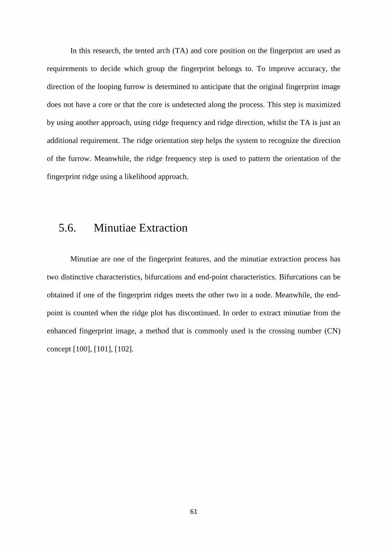
61
In this research, the tented arch (TA) and core position on the fingerprint are used as
requirements to decide which group the fingerprint belongs to. To improve accuracy, the
direction of the looping furrow is determined to anticipate that the original fingerprint image
does not have a core or that the core is undetected along the process. This step is maximized
by using another approach, using ridge frequency and ridge direction, whilst the TA is just an
additional requirement. The ridge orientation step helps the system to recognize the direction
of the furrow. Meanwhile, the ridge frequency step is used to pattern the orientation of the
fingerprint ridge using a likelihood approach.
5.6. Minutiae Extraction
Minutiae are one of the fingerprint features, and the minutiae extraction process has
two distinctive characteristics, bifurcations and end-point characteristics. Bifurcations can be
obtained if one of the fingerprint ridges meets the other two in a node. Meanwhile, the end-
point is counted when the ridge plot has discontinued. In order to extract minutiae from the
enhanced fingerprint image, a method that is commonly used is the crossing number (CN)
concept [100], [101], [102].
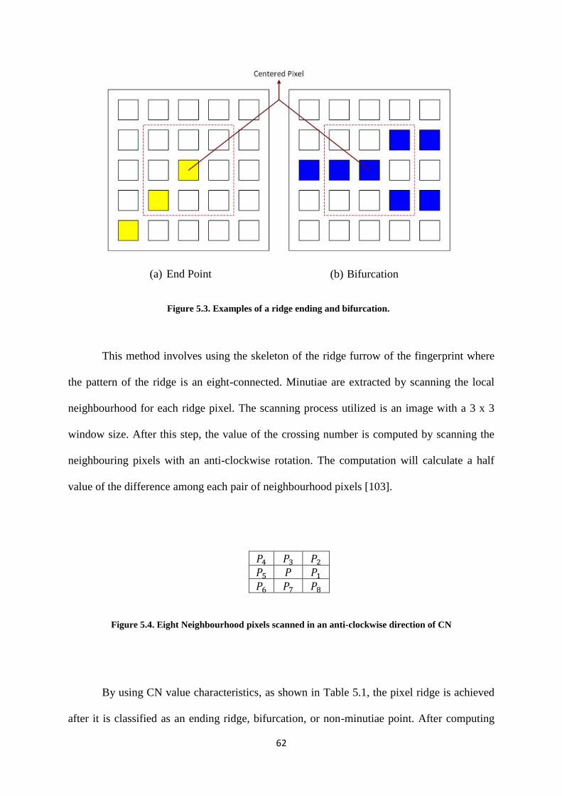
62
(a) End Point (b) Bifurcation
Figure 5.3. Examples of a ridge ending and bifurcation.
This method involves using the skeleton of the ridge furrow of the fingerprint where
the pattern of the ridge is an eight-connected. Minutiae are extracted by scanning the local
neighbourhood for each ridge pixel. The scanning process utilized is an image with a 3 x 3
window size. After this step, the value of the crossing number is computed by scanning the
neighbouring pixels with an anti-clockwise rotation. The computation will calculate a half
value of the difference among each pair of neighbourhood pixels [103].
𝑃4 𝑃3 𝑃2
𝑃5 𝑃 𝑃1
𝑃6 𝑃7 𝑃8
Figure 5.4. Eight Neighbourhood pixels scanned in an anti-clockwise direction of CN
By using CN value characteristics, as shown in Table 5.1, the pixel ridge is achieved
after it is classified as an ending ridge, bifurcation, or non-minutiae point. After computing

63
the CN value for the pixel ridge, the pixel from the new image can then be classified based on
of its CN value.
Table 5.1. Properties of CN
Crossing
Number
Properties
0 Isolated point
1 Ridge ending point
2 Continuing ridge point
3 Bifurcation point
4 Crossing point
(a) (b)
Figure 5.5. The candidate of ridge ending and ridge bifurcation (illustration using the properties of CN)
5.7. Experimental Results
In this research, three different databases are used to check to what extent the
algorithm is appropriate to be implemented. Those databases are: FVC 2002, DB1_B to
DB4_B; FVC 2004, DB1_B to DB4_B; and BRC, DBI/DBII/Training/Test. The results are
as follows.
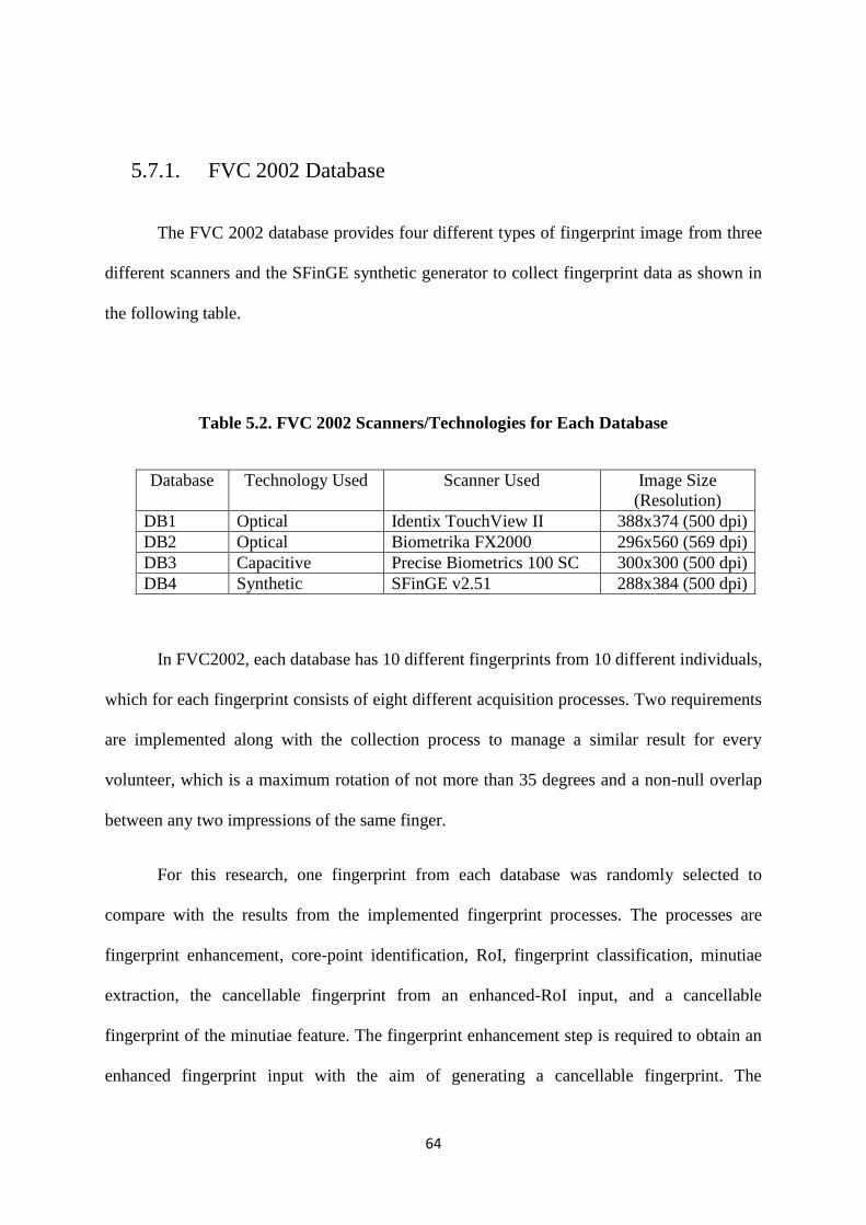
64
5.7.1. FVC 2002 Database
The FVC 2002 database provides four different types of fingerprint image from three
different scanners and the SFinGE synthetic generator to collect fingerprint data as shown in
the following table.
Table 5.2. FVC 2002 Scanners/Technologies for Each Database
Database Technology Used Scanner Used Image Size
(Resolution)
DB1 Optical Identix TouchView II 388x374 (500 dpi)
DB2 Optical Biometrika FX2000 296x560 (569 dpi)
DB3 Capacitive Precise Biometrics 100 SC 300x300 (500 dpi)
DB4 Synthetic SFinGE v2.51 288x384 (500 dpi)
In FVC2002, each database has 10 different fingerprints from 10 different individuals,
which for each fingerprint consists of eight different acquisition processes. Two requirements
are implemented along with the collection process to manage a similar result for every
volunteer, which is a maximum rotation of not more than 35 degrees and a non-null overlap
between any two impressions of the same finger.
For this research, one fingerprint from each database was randomly selected to
compare with the results from the implemented fingerprint processes. The processes are
fingerprint enhancement, core-point identification, RoI, fingerprint classification, minutiae
extraction, the cancellable fingerprint from an enhanced-RoI input, and a cancellable
fingerprint of the minutiae feature. The fingerprint enhancement step is required to obtain an
enhanced fingerprint input with the aim of generating a cancellable fingerprint. The
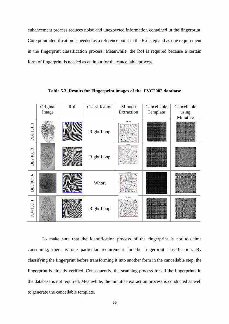
65
enhancement process reduces noise and unexpected information contained in the fingerprint.
Core point identification is needed as a reference point in the RoI step and as one requirement
in the fingerprint classification process. Meanwhile, the RoI is required because a certain
form of fingerprint is needed as an input for the cancellable process.
Table 5.3. Results for Fingerprint images of the FVC2002 database
Original
Image
RoI Classification Minutia
Extraction
Cancellable
Template
Cancellable
using
Minutiae
DB
1 1
01
_1
Right Loop
DB
2 1
06
_3
Right Loop
DB
3 1
07
_6
Whorl
DB
4 1
03
_1
Right Loop
To make sure that the identification process of the fingerprint is not too time
consuming, there is one particular requirement for the fingerprint classification. By
classifying the fingerprint before transforming it into another form in the cancellable step, the
fingerprint is already verified. Consequently, the scanning process for all the fingerprints in
the database is not required. Meanwhile, the minutiae extraction process is conducted as well
to generate the cancellable template.
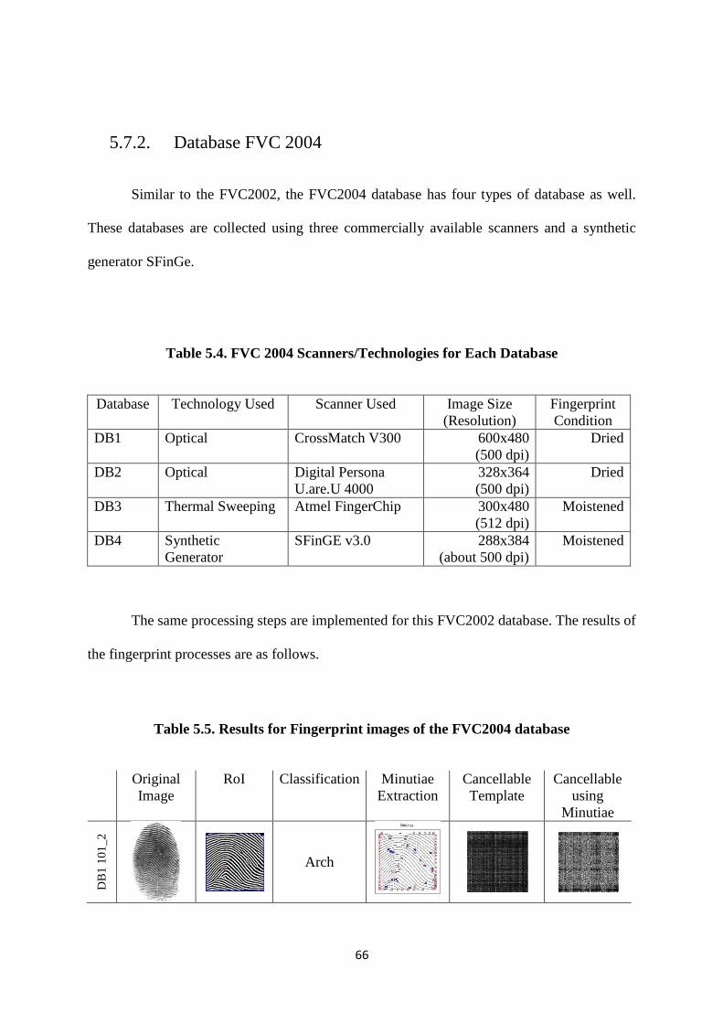
66
5.7.2. Database FVC 2004
Similar to the FVC2002, the FVC2004 database has four types of database as well.
These databases are collected using three commercially available scanners and a synthetic
generator SFinGe.
Table 5.4. FVC 2004 Scanners/Technologies for Each Database
Database Technology Used Scanner Used Image Size
(Resolution)
Fingerprint
Condition
DB1 Optical CrossMatch V300 600x480
(500 dpi)
Dried
DB2 Optical Digital Persona
U.are.U 4000
328x364
(500 dpi)
Dried
DB3 Thermal Sweeping Atmel FingerChip 300x480
(512 dpi)
Moistened
DB4 Synthetic
Generator
SFinGE v3.0 288x384
(about 500 dpi)
Moistened
The same processing steps are implemented for this FVC2002 database. The results of
the fingerprint processes are as follows.
Table 5.5. Results for Fingerprint images of the FVC2004 database
Original
Image
RoI Classification Minutiae
Extraction
Cancellable
Template
Cancellable
using
Minutiae
DB
1 1
01
_2
Arch
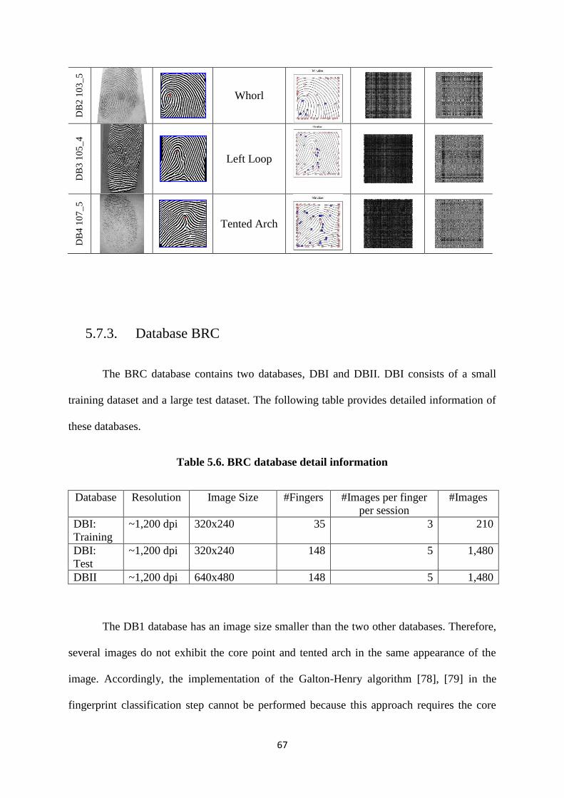
67
DB
2 1
03
_5
Whorl
DB
3 1
05
_4
Left Loop
DB
4 1
07
_5
Tented Arch
5.7.3. Database BRC
The BRC database contains two databases, DBI and DBII. DBI consists of a small
training dataset and a large test dataset. The following table provides detailed information of
these databases.
Table 5.6. BRC database detail information
Database Resolution Image Size #Fingers #Images per finger
per session
#Images
DBI:
Training
~1,200 dpi 320x240 35 3 210
DBI:
Test
~1,200 dpi 320x240 148 5 1,480
DBII ~1,200 dpi 640x480 148 5 1,480
The DB1 database has an image size smaller than the two other databases. Therefore,
several images do not exhibit the core point and tented arch in the same appearance of the
image. Accordingly, the implementation of the Galton-Henry algorithm [78], [79] in the
fingerprint classification step cannot be performed because this approach requires the core
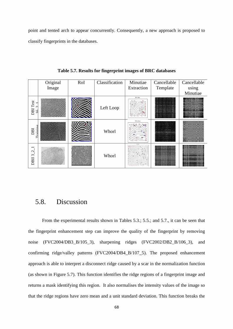
68
point and tented arch to appear concurrently. Consequently, a new approach is proposed to
classify fingerprints in the databases.
Table 5.7. Results for fingerprint images of BRC databases
Original
Image
RoI Classification Minutiae
Extraction
Cancellable
Template
Cancellable
using
Minutiae
DB
I T
est
16
_2_
1
Left Loop
DB
I
Tra
inin
g
30
7_1
_3
Whorl
DB
II 3
_2
_1
Whorl
5.8. Discussion
From the experimental results shown in Tables 5.3.; 5.5.; and 5.7., it can be seen that
the fingerprint enhancement step can improve the quality of the fingerprint by removing
noise (FVC2004/DB3_B/105_3), sharpening ridges (FVC2002/DB2_B/106_3), and
confirming ridge/valley patterns (FVC2004/DB4_B/107_5). The proposed enhancement
approach is able to interpret a disconnect ridge caused by a scar in the normalization function
(as shown in Figure 5.7). This function identifies the ridge regions of a fingerprint image and
returns a mask identifying this region. It also normalises the intensity values of the image so
that the ridge regions have zero mean and a unit standard deviation. This function breaks the
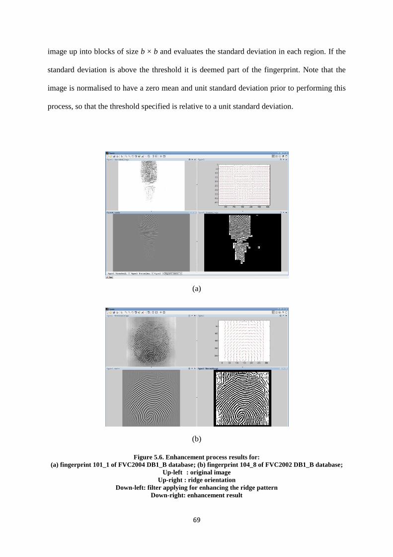
69
image up into blocks of size b × b and evaluates the standard deviation in each region. If the
standard deviation is above the threshold it is deemed part of the fingerprint. Note that the
image is normalised to have a zero mean and unit standard deviation prior to performing this
process, so that the threshold specified is relative to a unit standard deviation.
(a)
(b)
Figure 5.6. Enhancement process results for:
(a) fingerprint 101_1 of FVC2004 DB1_B database; (b) fingerprint 104_8 of FVC2002 DB1_B database;
Up-left : original image
Up-right : ridge orientation
Down-left: filter applying for enhancing the ridge pattern
Down-right: enhancement result
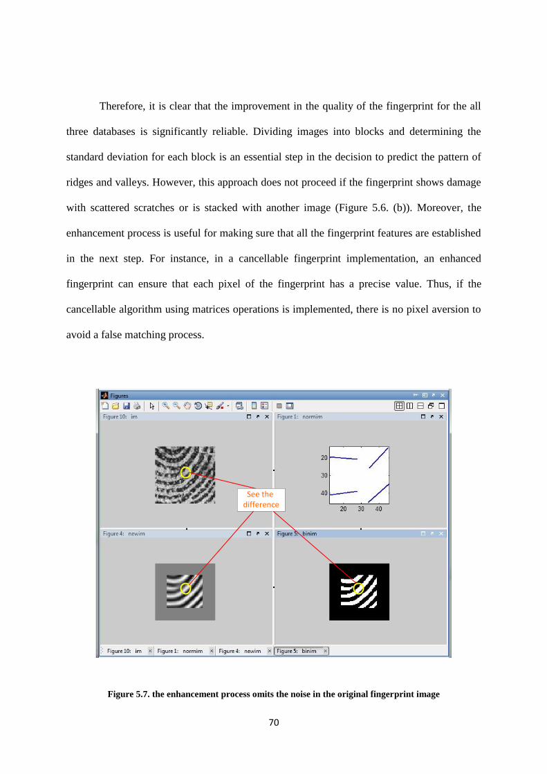
70
Therefore, it is clear that the improvement in the quality of the fingerprint for the all
three databases is significantly reliable. Dividing images into blocks and determining the
standard deviation for each block is an essential step in the decision to predict the pattern of
ridges and valleys. However, this approach does not proceed if the fingerprint shows damage
with scattered scratches or is stacked with another image (Figure 5.6. (b)). Moreover, the
enhancement process is useful for making sure that all the fingerprint features are established
in the next step. For instance, in a cancellable fingerprint implementation, an enhanced
fingerprint can ensure that each pixel of the fingerprint has a precise value. Thus, if the
cancellable algorithm using matrices operations is implemented, there is no pixel aversion to
avoid a false matching process.
See the difference
Figure 5.7. the enhancement process omits the noise in the original fingerprint image
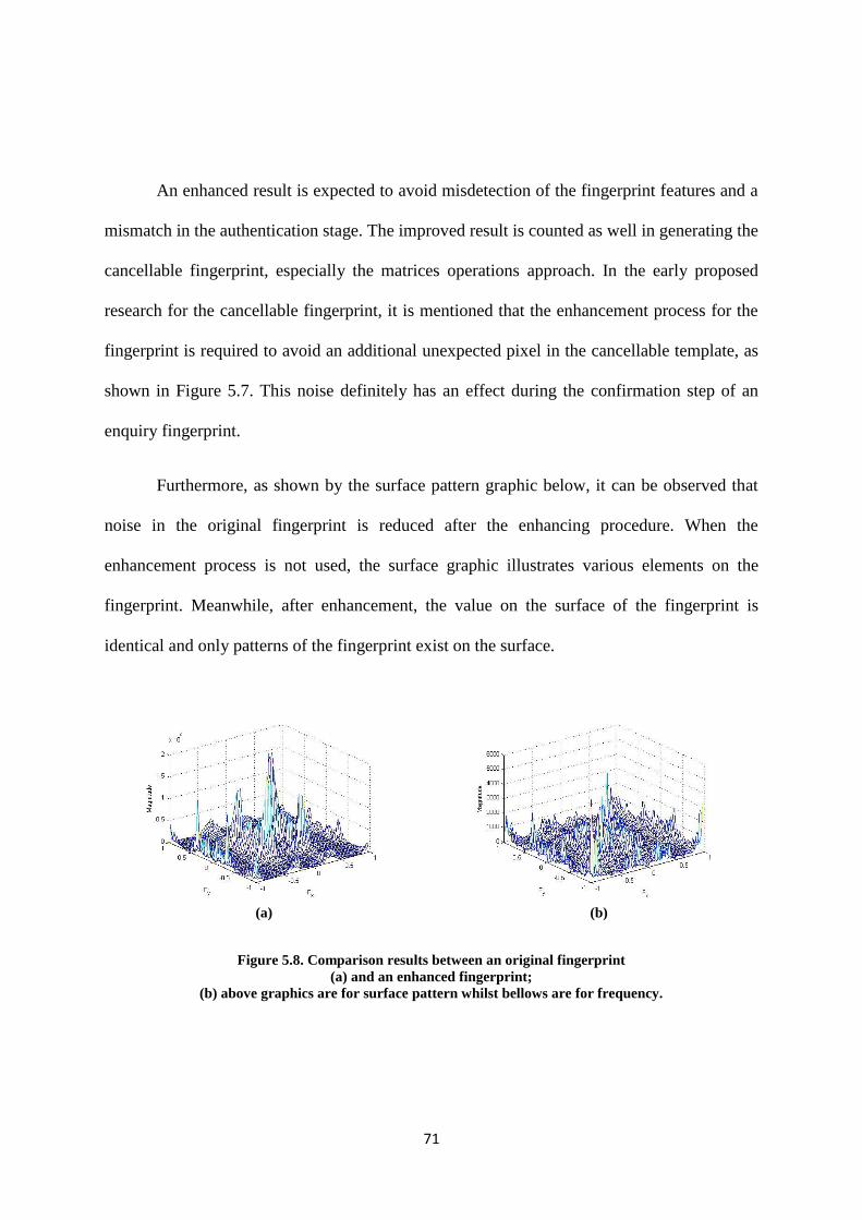
71
An enhanced result is expected to avoid misdetection of the fingerprint features and a
mismatch in the authentication stage. The improved result is counted as well in generating the
cancellable fingerprint, especially the matrices operations approach. In the early proposed
research for the cancellable fingerprint, it is mentioned that the enhancement process for the
fingerprint is required to avoid an additional unexpected pixel in the cancellable template, as
shown in Figure 5.7. This noise definitely has an effect during the confirmation step of an
enquiry fingerprint.
Furthermore, as shown by the surface pattern graphic below, it can be observed that
noise in the original fingerprint is reduced after the enhancing procedure. When the
enhancement process is not used, the surface graphic illustrates various elements on the
fingerprint. Meanwhile, after enhancement, the value on the surface of the fingerprint is
identical and only patterns of the fingerprint exist on the surface.
(a) (b)
Figure 5.8. Comparison results between an original fingerprint
(a) and an enhanced fingerprint;
(b) above graphics are for surface pattern whilst bellows are for frequency.
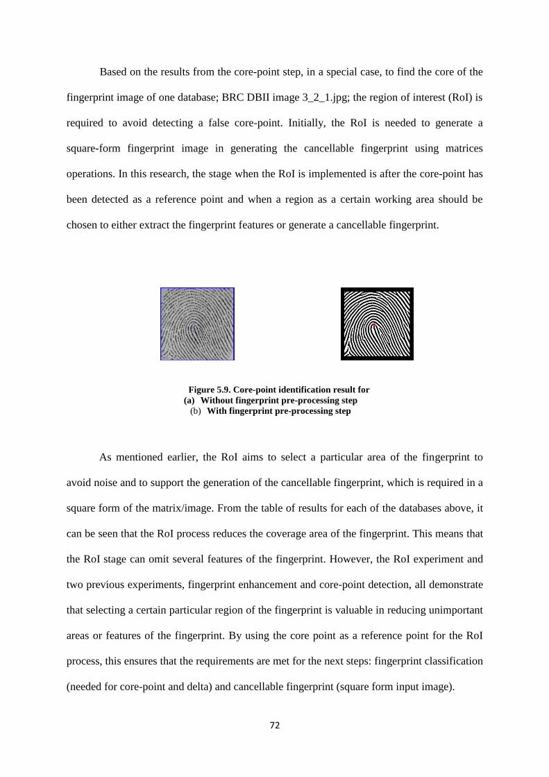
72
Based on the results from the core-point step, in a special case, to find the core of the
fingerprint image of one database; BRC DBII image 3_2_1.jpg; the region of interest (RoI) is
required to avoid detecting a false core-point. Initially, the RoI is needed to generate a
square-form fingerprint image in generating the cancellable fingerprint using matrices
operations. In this research, the stage when the RoI is implemented is after the core-point has
been detected as a reference point and when a region as a certain working area should be
chosen to either extract the fingerprint features or generate a cancellable fingerprint.
Figure 5.9. Core-point identification result for
(a) Without fingerprint pre-processing step
(b) With fingerprint pre-processing step
As mentioned earlier, the RoI aims to select a particular area of the fingerprint to
avoid noise and to support the generation of the cancellable fingerprint, which is required in a
square form of the matrix/image. From the table of results for each of the databases above, it
can be seen that the RoI process reduces the coverage area of the fingerprint. This means that
the RoI stage can omit several features of the fingerprint. However, the RoI experiment and
two previous experiments, fingerprint enhancement and core-point detection, all demonstrate
that selecting a certain particular region of the fingerprint is valuable in reducing unimportant
areas or features of the fingerprint. By using the core point as a reference point for the RoI
process, this ensures that the requirements are met for the next steps: fingerprint classification
(needed for core-point and delta) and cancellable fingerprint (square form input image).
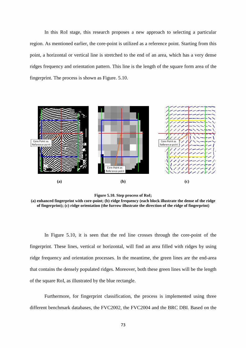
73
In this RoI stage, this research proposes a new approach to selecting a particular
region. As mentioned earlier, the core-point is utilized as a reference point. Starting from this
point, a horizontal or vertical line is stretched to the end of an area, which has a very dense
ridges frequency and orientation pattern. This line is the length of the square form area of the
fingerprint. The process is shown as Figure. 5.10.
(a)
(b)
(c)
Figure 5.10. Step process of RoI;
(a) enhanced fingerprint with core-point; (b) ridge frequency (each block illustrate the dense of the ridge
of fingerprint); (c) ridge orientation (the furrow illustrate the direction of the ridge of fingerprint)
In Figure 5.10, it is seen that the red line crosses through the core-point of the
fingerprint. These lines, vertical or horizontal, will find an area filled with ridges by using
ridge frequency and orientation processes. In the meantime, the green lines are the end-area
that contains the densely populated ridges. Moreover, both these green lines will be the length
of the square RoI, as illustrated by the blue rectangle.
Furthermore, for fingerprint classification, the process is implemented using three
different benchmark databases, the FVC2002, the FVC2004 and the BRC DBI. Based on the

74
examples of the five commonly used fingerprint classes under the Galton-Henry
classification scheme, the classification results for the three databases are as follows.
a. FVC2002
In this database, there are 320 fingerprints divided into four different sub-databases,
which each sub-databases consist of 10 types of fingerprints from 10 different
individuals. Each fingerprint has 8 different acquisitions of a fingerprint.
Table 5.8. Fingerprint Classification for the FVC2002 Database under the
Galton-Henry Classification Scheme
No. Type of Classification Percentage
1. Arch 0.00
2. Tented Arch 0.00
3. Left Loop 10.31
4. Right Loop 18.44
5. Whorl 15.31
6. Twin Loop Whorl 7.19
Meanwhile, the percentage of the classification based on the existence of the
fingerprint type is as follows.
Table 5.9. Fingerprint Classification for the FVC2002 Database based on
the Existence of the Fingerprint
No. Type of Classification Percentage
1. Classified 51.25
2. Unclassified 5.94
3. Indicated as Left/Right Loop 41.56
4. False Classification 1.25

75
b. FVC2004
This database has the same division and total number of fingerprints as FVC2002.
Table 5.10. Fingerprint Classification for the FVC2004 Database under the
Galton-Henry Classification Scheme
No. Type of Classification Percentage
1. Arch 2.50
2. Tented Arch 2.50
3. Left Loop 16.87
4. Right Loop 5.31
5. Whorl 21.87
6. Twin Loop Whorl 10.00
Meanwhile, the percentage of the classification based on the existence of the
fingerprint type is as follows.
Table 5.11. Fingerprint Classification for the FVC2004 Database based on
the Existence of the Fingerprint
No. Type of Classification Percentage
1. Classified 59.06
2. Unclassified 1.56
3. Indicated as Left/Right Loop 35.94
4. False Classification 3.44
c. BRC DBI
Allotment in the BRC database is different from that in the two previous databases.
This database has 1480 types of fingerprints, which are divided into two different sub
types for each type and five different fingerprints in one sub-type.

76
Table 5.12. Fingerprint Classification for the BRC DBI-Test Database under the
Galton-Henry Classification Scheme plus Four New Types of Fingerprint
No. Type of Classification Percentage
1. Arch 2.57
2. Tented Arch 0.00
3. Left Loop 1.89
4. Right Loop 1.01
5. Whorl 12.43
6. Twin Loop Whorl 12.91
7. Type 1 (Microphone) 0.68
8. Type 2 (Solar Whorl) 2.09
9. Type 3 (Closed-Left Loop) 1.15
10. Type 4 (Loop-Whorl-Arch) 0.47
The percentage of the classification based on the existence of the fingerprint type is as
follows.
Table 5.13. Fingerprint Classification for the BRC DBI-Test Database based on
the Existence of the Fingerprint
No. Type of Classification Percentage
1. Classified 34.80
2. Unclassified 17.30
3. Indicated as Left/Right Loop 36.82
4. False Classification 11.08
The classification process is conducted by implementing the fingerprint classes
proposed by Henry-Galton. There are six different classes used in the Henry-Galton
classification scheme which are arch, tented arch, left loop, right loop, whorl and twin loop
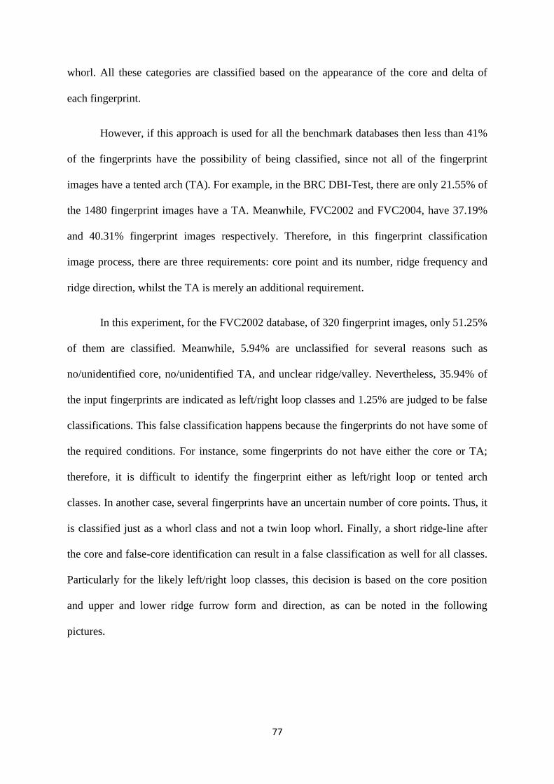
77
whorl. All these categories are classified based on the appearance of the core and delta of
each fingerprint.
However, if this approach is used for all the benchmark databases then less than 41%
of the fingerprints have the possibility of being classified, since not all of the fingerprint
images have a tented arch (TA). For example, in the BRC DBI-Test, there are only 21.55% of
the 1480 fingerprint images have a TA. Meanwhile, FVC2002 and FVC2004, have 37.19%
and 40.31% fingerprint images respectively. Therefore, in this fingerprint classification
image process, there are three requirements: core point and its number, ridge frequency and
ridge direction, whilst the TA is merely an additional requirement.
In this experiment, for the FVC2002 database, of 320 fingerprint images, only 51.25%
of them are classified. Meanwhile, 5.94% are unclassified for several reasons such as
no/unidentified core, no/unidentified TA, and unclear ridge/valley. Nevertheless, 35.94% of
the input fingerprints are indicated as left/right loop classes and 1.25% are judged to be false
classifications. This false classification happens because the fingerprints do not have some of
the required conditions. For instance, some fingerprints do not have either the core or TA;
therefore, it is difficult to identify the fingerprint either as left/right loop or tented arch
classes. In another case, several fingerprints have an uncertain number of core points. Thus, it
is classified just as a whorl class and not a twin loop whorl. Finally, a short ridge-line after
the core and false-core identification can result in a false classification as well for all classes.
Particularly for the likely left/right loop classes, this decision is based on the core position
and upper and lower ridge furrow form and direction, as can be noted in the following
pictures.
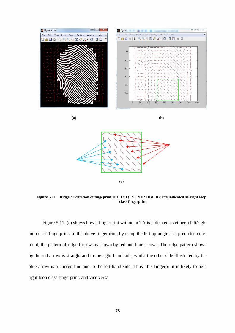
78
(a)
(b)
(c)
Figure 5.11. Ridge orientation of fingeprint 101_1.tif (FVC2002 DB1_B); It’s indicated as right loop
class fingerprint
Figure 5.11. (c) shows how a fingerprint without a TA is indicated as either a left/right
loop class fingerprint. In the above fingerprint, by using the left up-angle as a predicted core-
point, the pattern of ridge furrows is shown by red and blue arrows. The ridge pattern shown
by the red arrow is straight and to the right-hand side, whilst the other side illustrated by the
blue arrow is a curved line and to the left-hand side. Thus, this fingerprint is likely to be a
right loop class fingerprint, and vice versa.

79
Furthermore, for FVC2004, as shown in Table 3.7., the percentage of classified
fingerprints is slightly higher than for FVC2002. This is because the fingerprint input size in
FVC2004 is bigger, so that fingerprint details like the core and TA are better covered than in
FVC2002. Nevertheless, since the acquisition quality of FVC2004 is lower than 2002, the
percentage of false classifications in FVC2004 is higher than in FVC2002.
Meanwhile, in the BRC DBI-Test case, as the size of the fingerprints is smaller than
in the two previous databases, it does not provide enough detailed information to classify the
fingerprint core, TA and sufficient ridge length after the core. This causes the percentage of
false classifications and unclassified fingerprint to be higher than with the two other
databases, as shown by the Table 5.14.
Table 5.14. The comparison results of three different databases in terms of classified,
unclassified, indicated as left/right loop and a false classification decision.
No. Classification Decision FVC2002 FVC2004 BRC DBI Test
As a percentage
1. Classified 51.25 59.06 34.8
2. Unclassified 5.94 1.56 17.3
3. Indicated as left/right loop 41.56 35.94 36.82
4. False classification 1.25 3.44 11.08
However, in this database, it is found four new fingerprint types are found as follows.
80
(a) (b) (c) (d)
Figure 5.12. Indicated as a new type of fingerprint (beside Henry-Galton fingerprint classes)
In summary, the fingerprint classification process is influenced by the quality and the
feature of the fingerprint. If the fingerprint acquisition provides a superior quality image, or at
least the image enhancement step improves the quality, then the detailed information required
to classify the fingerprint as well as for the covered region is available, Moreover, to improve
the number of classified fingerprints, the use of the tented arch (TA) as a requirement can be
maximized by using instead the ridge frequency and ridge direction, so that the TA is just an
additional requirement.
In the feature extraction step, the experiment still uses three different benchmark
databases. The results demonstrate that the proposed extraction approach works well for all
the databases. It can be seen that the algorithm progressively separates each type of minutiae;
bifurcation (blue square symbols) and end point (red square symbols), and removes the false
minutiae as well. However, it is recognized further that this algorithm has to be improved to
obtain a higher accuracy results for all the different databases. The drawback is that this
approach still counts the boundaries of the input as part of the minutiae extraction. This
“additional minutiae” will increase the threshold error level in the authentication step.

81
(a) (b)
Figure 5.13. Frequency Display for Cancellable Result of Fingerprint 107_6 of Database 2002 DB3
(a) For an enhanced fingerprint input
(b) For minutiae input
Finally, in this research, minutiae features are determined as an input to generate the
cancellable template. This idea has the basis that minutiae are already an unknown object and
information for the impostor. When the minutiae comparing to a fingerprint image, the
minutiae are initially only coloured dots which are displayed without the fingerprint, as
shown in Figure 5.13.
5.9. Summary
In generating cancellable fingerprints, there are several steps that are required. Firstly,
enhancement is required to improve the quality of the fingerprint. A superior enhanced
feature will make large amounts of information possible such as minutiae, core point, and
fingerprint classification. The presence of this information is very important because, in this
cancellable approach, there is a step where some of the parts will be modified or reduced.

82
It is possible to use minutiae as an input to generate the cancellable template feature.
The information about bifurcations and end points that is illustrated by the coloured dots can
deceive an impostor as the minutiae do not look like a fingerprint. This helps us to implement
either the second or the third method for the cancellable research outline described in the
previous chapter, so as to generate the cancellable feature.
To obtain a dependable cancellable feature, several fingerprint processes are required:
fingerprint enhancement, core-point identification, region of interest (RoI), fingerprint
classification and minutiae extraction. Based on the results from all the experiments, the
following conclusions can be drawn:
(1) Fingerprint enhancement is required to produce a clear input for all the subsequent
fingerprint processes. For example, an enhanced fingerprint provides a clear input image to
avoid a false core-point detection and false minutiae extraction. Moreover, a fingerprint input
free of noise is useful to avoid establishing an unimportant pixel in a cancellable fingerprint
template by using matrices operations.
(2) In this research, the core-point detection approach is not only appropriate for one
type of database. It can be implemented with different types of databases. This improvement
in results is achieved if the input is an enhanced image. Otherwise, if a poor quality image
becomes the input, the proposed approach detects a false core-point. As the core-point is
utilized in the RoI and fingerprint classification steps, this result has an impact to achieve a
progressive result and vice versa.
(3) A novel approach is proposed to select a particular area in the RoI step, in order to
accommodate the needs of a square input form for the cancellable fingerprint and the need to
omit unimportant areas for the minutiae extraction step. Even though the RoI stage reduces

83
the area of the fingerprint, this step is required so that noise in the fingerprint image can be
eliminated.
(4) Minutiae extraction gives an alternative possibility for use as an input for the
cancellable fingerprint template, given that its appearance is not like an initial fingerprint.
Moreover, minutiae information describes common data differently from mere fingerprint
data. Based on these points, the performance evaluation of all applications is determined in
the following chapter to achieve better results. Furthermore, the idea of using minutiae
extraction as an input to generate a cancellable template is also analyzed.
84
Chapter 6
6. Performance Analysis
6.1. Introduction
The assessment of reliability in a biometric system cannot be separated from
performance evaluation. Each approach implemented in biometrics, such as fingerprints will
obviously provide a different result depending on the type of database utilized in the research.
Previous researchers have proven that the performance of the matcher drastically decreases
when the fingerprints to be compared originated from sensors with different resolutions
[104]. The performance of the method proposed here is analyzed using eleven different
databases which have different sizes, resolutions and characteristics, which are the FVC2002
(databases 1, 2, 3, and 4), FVC2004 (databases 1, 2, 3, and 4), and BRC (database I, test and
training; and database II). For the FVC2002 and FVC2004 databases, there are ten different
fingerprints with eight different acquisition processes. Meanwhile for the BRC database,
there are ten kinds of fingerprints with six different enrolments.
6.2. Error Rates
The authentication step evaluates the ability of the proposed method to authenticate
whether the inputs of the fingerprint are a genuine owner or an impostor. This categorizing
process validates the genuine nature of the fingerprint by implementing various steps, as a
score for both an established fingerprint and the input fingerprint as an enquiry fingerprint.
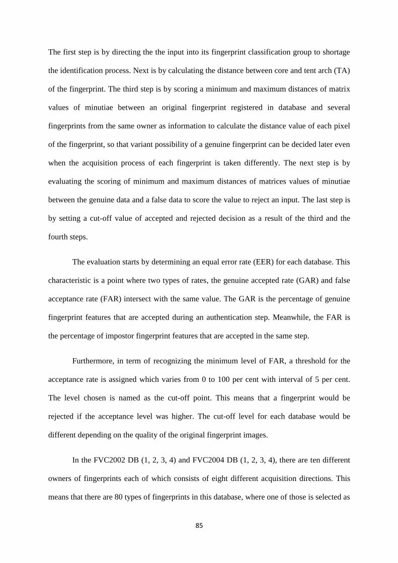
85
The first step is by directing the the input into its fingerprint classification group to shortage
the identification process. Next is by calculating the distance between core and tent arch (TA)
of the fingerprint. The third step is by scoring a minimum and maximum distances of matrix
values of minutiae between an original fingerprint registered in database and several
fingerprints from the same owner as information to calculate the distance value of each pixel
of the fingerprint, so that variant possibility of a genuine fingerprint can be decided later even
when the acquisition process of each fingerprint is taken differently. The next step is by
evaluating the scoring of minimum and maximum distances of matrices values of minutiae
between the genuine data and a false data to score the value to reject an input. The last step is
by setting a cut-off value of accepted and rejected decision as a result of the third and the
fourth steps.
The evaluation starts by determining an equal error rate (EER) for each database. This
characteristic is a point where two types of rates, the genuine accepted rate (GAR) and false
acceptance rate (FAR) intersect with the same value. The GAR is the percentage of genuine
fingerprint features that are accepted during an authentication step. Meanwhile, the FAR is
the percentage of impostor fingerprint features that are accepted in the same step.
Furthermore, in term of recognizing the minimum level of FAR, a threshold for the
acceptance rate is assigned which varies from 0 to 100 per cent with interval of 5 per cent.
The level chosen is named as the cut-off point. This means that a fingerprint would be
rejected if the acceptance level was higher. The cut-off level for each database would be
different depending on the quality of the original fingerprint images.
In the FVC2002 DB (1, 2, 3, 4) and FVC2004 DB (1, 2, 3, 4), there are ten different
owners of fingerprints each of which consists of eight different acquisition directions. This
means that there are 80 types of fingerprints in this database, where one of those is selected as

86
the owner represented in the database. From the 79 fingerprints which are left, only seven are
categorized into accepted, rejected, false accepted, and false rejected, while the remaining 72
are completely rejected and are not included in those categories as a result of the
implementation of the classification step. Seven fingerprints are accepted since their
acceptance rates are higher than the cut-off value.
This step not only saves time during the process, but also helps the system to reduce
the number of fingerprints needing to be to analyzed. During this stage, an enquiry input will
be grouped into its particular class so that an inappropriate fingerprint would be rejected
automatically before proceeding to the matching step. Given that each fingerprint in the same
database is already categorized into its own class, the percentage EERs for the databases are
illustrated in the following eight tables (Tables 6.1 - 6.8).
Table 6.1. EER values for FVC 2002 DB1
Fingerprint EER FAR Cut-off point
101 0.063 0.125 0.425
102 0.125 0.250 0.275
103 0.063 0.125 0.075
104 0.063 0.125 0.375
105 0.250 0.500 0.275
106 0.063 0.125 0.125
107 0.063 0.125 0.475
108 0.125 0.250 0.475
109 0.125 0.250 0.475
110 0.063 0.125 0.225
In Table 6.1, it can be noted that the EERs vary, with values of 0.063 and 0.125; and
0.250 for the cut-off point which varies from 0.075 to 0.475. The higher value of the cut-off
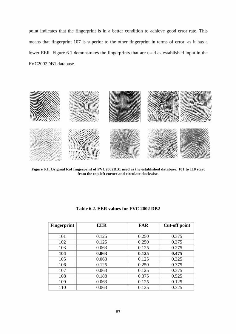
87
point indicates that the fingerprint is in a better condition to achieve good error rate. This
means that fingerprint 107 is superior to the other fingerprint in terms of error, as it has a
lower EER. Figure 6.1 demonstrates the fingerprints that are used as established input in the
FVC2002DB1 database.
Figure 6.1. Original RoI fingerprint of FVC2002DB1 used as the established database; 101 to 110 start
from the top left corner and circulate clockwise.
Table 6.2. EER values for FVC 2002 DB2
Fingerprint EER FAR Cut-off point
101 0.125 0.250 0.375
102 0.125 0.250 0.375
103 0.063 0.125 0.275
104 0.063 0.125 0.475
105 0.063 0.125 0.325
106 0.125 0.250 0.375
107 0.063 0.125 0.375
108 0.188 0.375 0.525
109 0.063 0.125 0.125
110 0.063 0.125 0.325
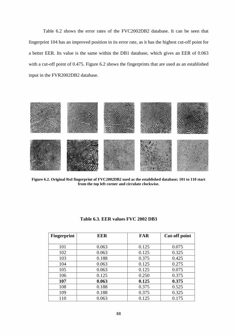
88
Table 6.2 shows the error rates of the FVC2002DB2 database. It can be seen that
fingerprint 104 has an improved position in its error rate, as it has the highest cut-off point for
a better EER. Its value is the same within the DB1 database, which gives an EER of 0.063
with a cut-off point of 0.475. Figure 6.2 shows the fingerprints that are used as an established
input in the FVR2002DB2 database.
Figure 6.2. Original RoI fingerprint of FVC2002DB2 used as the established database; 101 to 110 start
from the top left corner and circulate clockwise.
Table 6.3. EER values FVC 2002 DB3
Fingerprint EER FAR Cut-off point
101 0.063 0.125 0.075
102 0.063 0.125 0.325
103 0.188 0.375 0.425
104 0.063 0.125 0.275
105 0.063 0.125 0.075
106 0.125 0.250 0.375
107 0.063 0.125 0.375
108 0.188 0.375 0.525
109 0.188 0.375 0.325
110 0.063 0.125 0.175
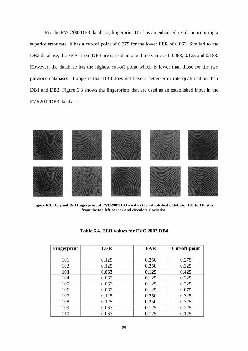
89
For the FVC2002DB3 database, fingerprint 107 has an enhanced result in acquiring a
superior error rate. It has a cut-off point of 0.375 for the lower EER of 0.063. Similarl to the
DB2 database, the EERs from DB3 are spread among three values of 0.063, 0.125 and 0.188.
However, the database has the highest cut-off point which is lower than those for the two
previous databases. It appears that DB3 does not have a better error rate qualification than
DB1 and DB2. Figure 6.3 shows the fingerprints that are used as an established input in the
FVR2002DB3 database.
Figure 6.3. Original RoI fingerprint of FVC2002DB3 used as the established database; 101 to 110 start
from the top left corner and circulate clockwise.
Table 6.4. EER values for FVC 2002 DB4
Fingerprint EER FAR Cut-off point
101 0.125 0.250 0.275
102 0.125 0.250 0.325
103 0.063 0.125 0.425
104 0.063 0.125 0.225
105 0.063 0.125 0.325
106 0.063 0.125 0.075
107 0.125 0.250 0.325
108 0.125 0.250 0.325
109 0.063 0.125 0.225
110 0.063 0.125 0.125

90
As with the three previous databases, the FVC2002DB4 database has the lowest EER
at 0.063. However, it has the lowest EERs compared with the other databases of 0.063 and
0.125. In addition, fingerprint 103 has a superior error rate compared to the others, attaining
an EER of 0.063 for a 0.425 cut-off point position.
Figure 6.4. Original RoI fingerprint of FVC2002DB4 used as the established database; 101 to 110 start
from the top left corner and circulate clockwise.
Overall, the technology used in the FVC2004 database is similar to that of the
FVC2002 database, except for the DB3database. In FVC2002DB3, the technology that is
used is capacitive, using a Precise Biometrics 100 SC scanner. Meanwhile, in FVC2004DB3
the technology has changed to a thermal sweeping application using an Atmel FingerChip
scanner. Despite the similarity amongst the three other databases, all the databases in
FVC2004 use different scanners to acquire the fingerprint.
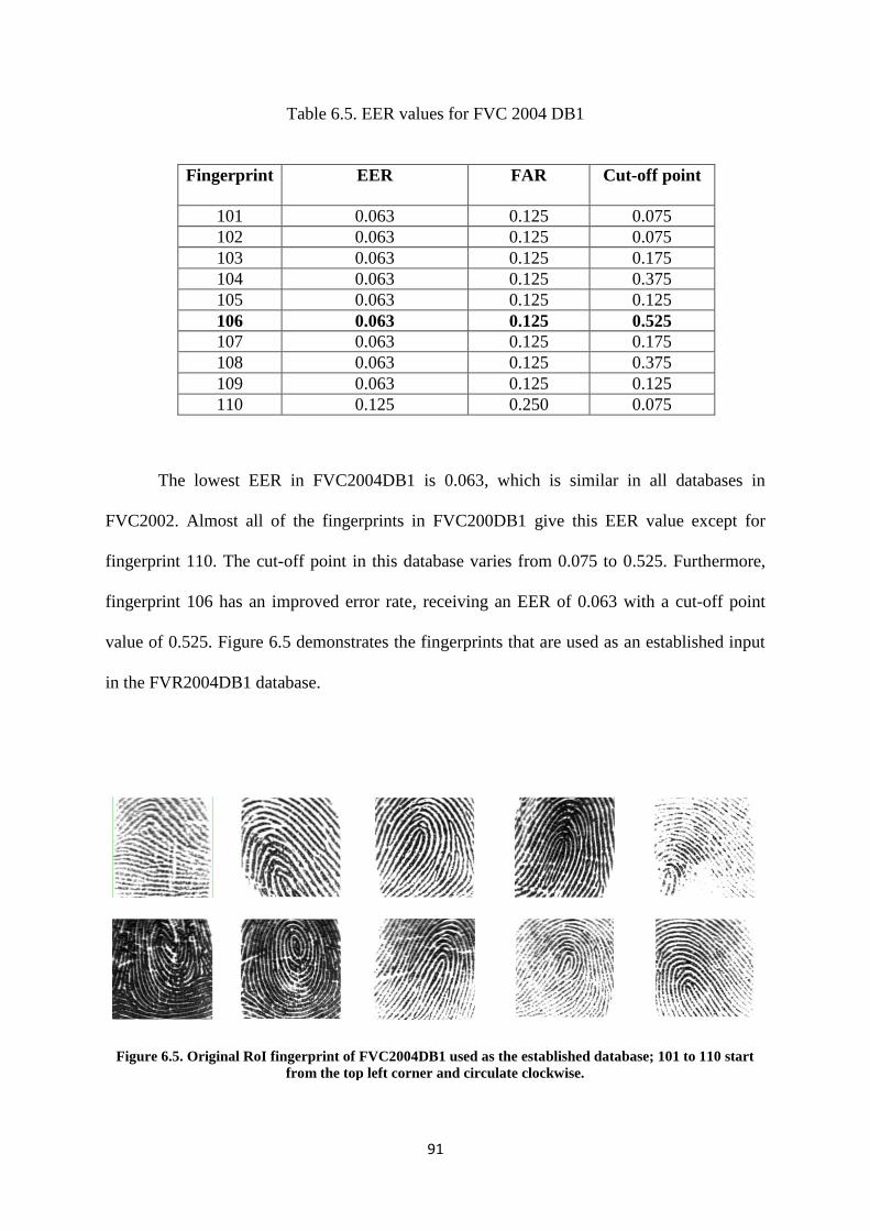
91
Table 6.5. EER values for FVC 2004 DB1
Fingerprint EER FAR Cut-off point
101 0.063 0.125 0.075
102 0.063 0.125 0.075
103 0.063 0.125 0.175
104 0.063 0.125 0.375
105 0.063 0.125 0.125
106 0.063 0.125 0.525
107 0.063 0.125 0.175
108 0.063 0.125 0.375
109 0.063 0.125 0.125
110 0.125 0.250 0.075
The lowest EER in FVC2004DB1 is 0.063, which is similar in all databases in
FVC2002. Almost all of the fingerprints in FVC200DB1 give this EER value except for
fingerprint 110. The cut-off point in this database varies from 0.075 to 0.525. Furthermore,
fingerprint 106 has an improved error rate, receiving an EER of 0.063 with a cut-off point
value of 0.525. Figure 6.5 demonstrates the fingerprints that are used as an established input
in the FVR2004DB1 database.
Figure 6.5. Original RoI fingerprint of FVC2004DB1 used as the established database; 101 to 110 start
from the top left corner and circulate clockwise.
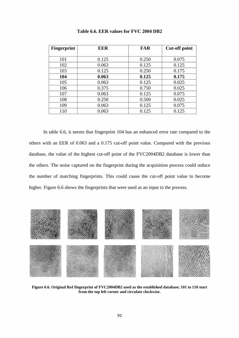
92
Table 6.6. EER values for FVC 2004 DB2
Fingerprint EER FAR Cut-off point
101 0.125 0.250 0.075
102 0.063 0.125 0.125
103 0.125 0.250 0.175
104 0.063 0.125 0.175
105 0.063 0.125 0.025
106 0.375 0.750 0.025
107 0.063 0.125 0.075
108 0.250 0.500 0.025
109 0.063 0.125 0.075
110 0.063 0.125 0.125
In table 6.6, it seems that fingerprint 104 has an enhanced error rate compared to the
others with an EER of 0.063 and a 0.175 cut-off point value. Compared with the previous
database, the value of the highest cut-off point of the FVC2004DB2 database is lower than
the others. The noise captured on the fingerprint during the acquisition process could reduce
the number of matching fingerprints. This could cause the cut-off point value to become
higher. Figure 6.6 shows the fingerprints that were used as an input in the process.
Figure 6.6. Original RoI fingerprint of FVC2004DB2 used as the established database; 101 to 110 start
from the top left corner and circulate clockwise.
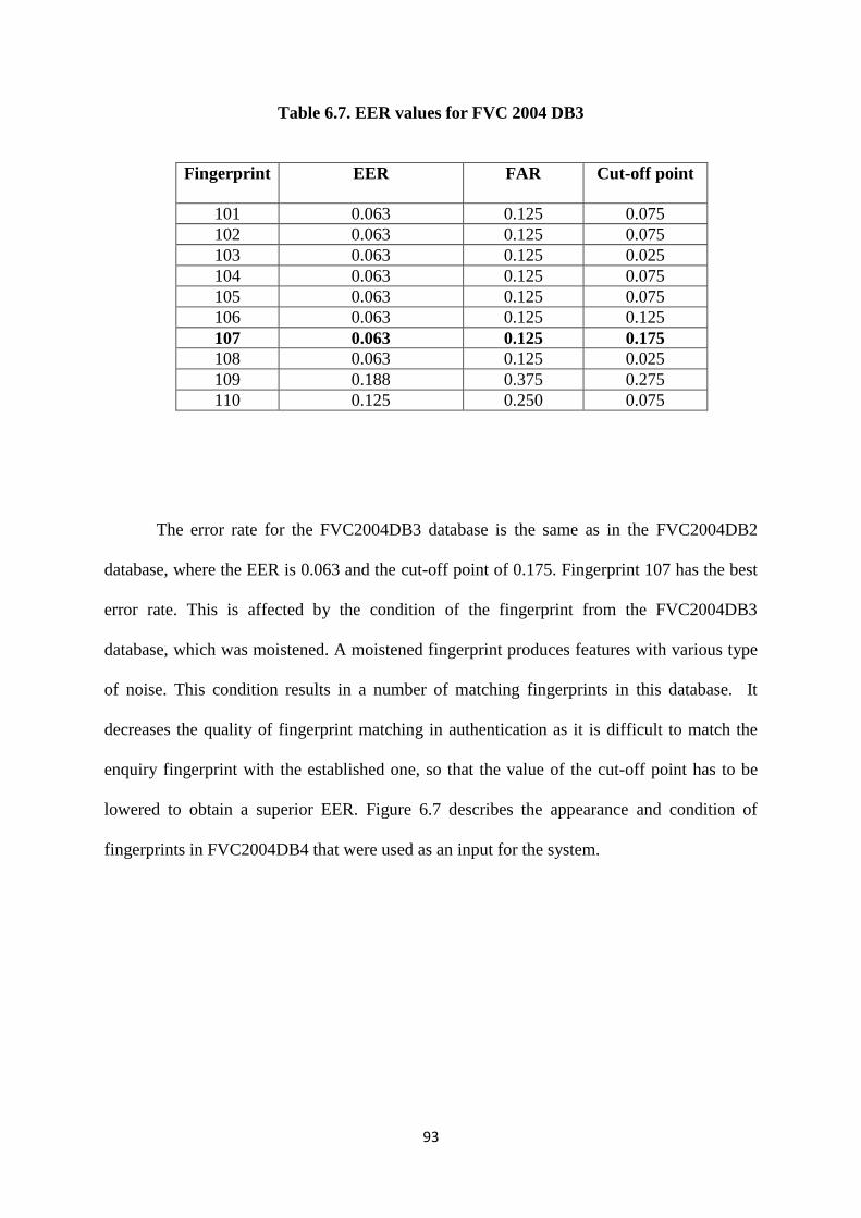
93
Table 6.7. EER values for FVC 2004 DB3
Fingerprint EER FAR Cut-off point
101 0.063 0.125 0.075
102 0.063 0.125 0.075
103 0.063 0.125 0.025
104 0.063 0.125 0.075
105 0.063 0.125 0.075
106 0.063 0.125 0.125
107 0.063 0.125 0.175
108 0.063 0.125 0.025
109 0.188 0.375 0.275
110 0.125 0.250 0.075
The error rate for the FVC2004DB3 database is the same as in the FVC2004DB2
database, where the EER is 0.063 and the cut-off point of 0.175. Fingerprint 107 has the best
error rate. This is affected by the condition of the fingerprint from the FVC2004DB3
database, which was moistened. A moistened fingerprint produces features with various type
of noise. This condition results in a number of matching fingerprints in this database. It
decreases the quality of fingerprint matching in authentication as it is difficult to match the
enquiry fingerprint with the established one, so that the value of the cut-off point has to be
lowered to obtain a superior EER. Figure 6.7 describes the appearance and condition of
fingerprints in FVC2004DB4 that were used as an input for the system.
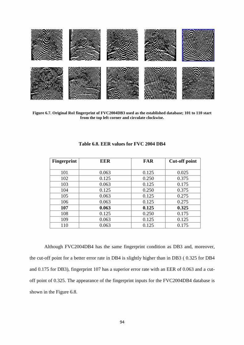
94
Figure 6.7. Original RoI fingerprint of FVC2004DB3 used as the established database; 101 to 110 start
from the top left corner and circulate clockwise.
Table 6.8. EER values for FVC 2004 DB4
Fingerprint EER FAR Cut-off point
101 0.063 0.125 0.025
102 0.125 0.250 0.375
103 0.063 0.125 0.175
104 0.125 0.250 0.375
105 0.063 0.125 0.275
106 0.063 0.125 0.275
107 0.063 0.125 0.325
108 0.125 0.250 0.175
109 0.063 0.125 0.125
110 0.063 0.125 0.175
Although FVC2004DB4 has the same fingerprint condition as DB3 and, moreover,
the cut-off point for a better error rate in DB4 is slightly higher than in DB3 ( 0.325 for DB4
and 0.175 for DB3), fingerprint 107 has a superior error rate with an EER of 0.063 and a cut-
off point of 0.325. The appearance of the fingerprint inputs for the FVC2004DB4 database is
shown in the Figure 6.8.
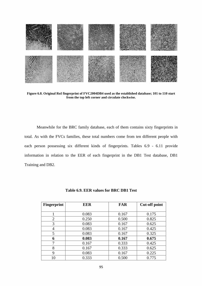
95
Figure 6.8. Original RoI fingerprint of FVC2004DB4 used as the established database; 101 to 110 start
from the top left corner and circulate clockwise.
Meanwhile for the BRC family database, each of them contains sixty fingerprints in
total. As with the FVCs families, these total numbers come from ten different people with
each person possessing six different kinds of fingerprints. Tables 6.9 - 6.11 provide
information in relation to the EER of each fingerprint in the DB1 Test database, DB1
Training and DB2.
Table 6.9. EER values for BRC DB1 Test
Fingerprint EER FAR Cut-off point
1 0.083 0.167 0.175
2 0.250 0.500 0.825
3 0.083 0.167 0.625
4 0.083 0.167 0.425
5 0.083 0.167 0.325
6 0.083 0.167 0.675
7 0.167 0.333 0.425
8 0.167 0.333 0.625
9 0.083 0.167 0.225
10 0.333 0.500 0.775
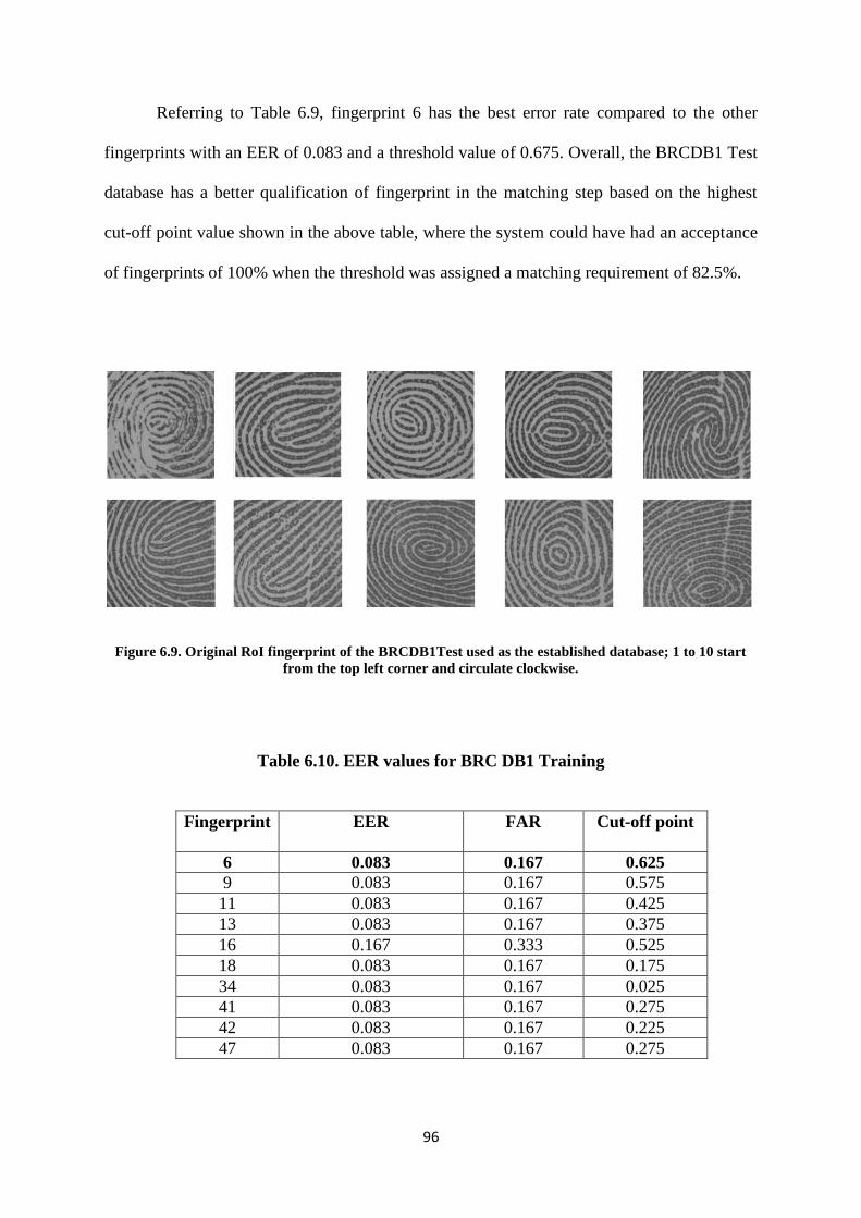
96
Referring to Table 6.9, fingerprint 6 has the best error rate compared to the other
fingerprints with an EER of 0.083 and a threshold value of 0.675. Overall, the BRCDB1 Test
database has a better qualification of fingerprint in the matching step based on the highest
cut-off point value shown in the above table, where the system could have had an acceptance
of fingerprints of 100% when the threshold was assigned a matching requirement of 82.5%.
Figure 6.9. Original RoI fingerprint of the BRCDB1Test used as the established database; 1 to 10 start
from the top left corner and circulate clockwise.
Table 6.10. EER values for BRC DB1 Training
Fingerprint EER FAR Cut-off point
6 0.083 0.167 0.625
9 0.083 0.167 0.575
11 0.083 0.167 0.425
13 0.083 0.167 0.375
16 0.167 0.333 0.525
18 0.083 0.167 0.175
34 0.083 0.167 0.025
41 0.083 0.167 0.275
42 0.083 0.167 0.225
47 0.083 0.167 0.275
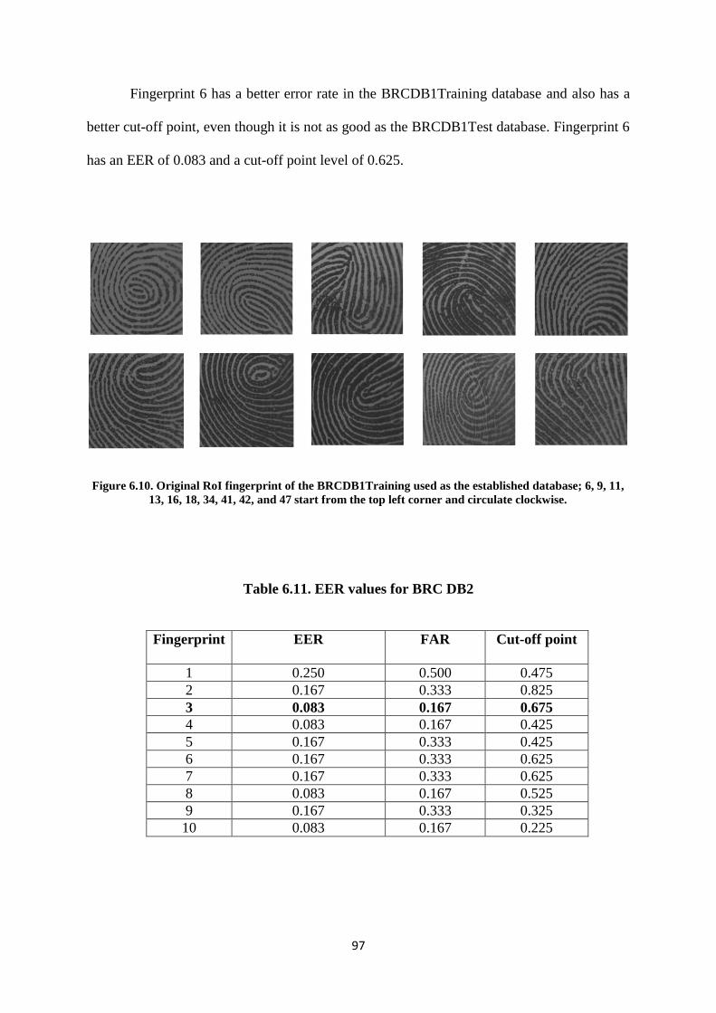
97
Fingerprint 6 has a better error rate in the BRCDB1Training database and also has a
better cut-off point, even though it is not as good as the BRCDB1Test database. Fingerprint 6
has an EER of 0.083 and a cut-off point level of 0.625.
Figure 6.10. Original RoI fingerprint of the BRCDB1Training used as the established database; 6, 9, 11,
13, 16, 18, 34, 41, 42, and 47 start from the top left corner and circulate clockwise.
Table 6.11. EER values for BRC DB2
Fingerprint EER FAR Cut-off point
1 0.250 0.500 0.475
2 0.167 0.333 0.825
3 0.083 0.167 0.675
4 0.083 0.167 0.425
5 0.167 0.333 0.425
6 0.167 0.333 0.625
7 0.167 0.333 0.625
8 0.083 0.167 0.525
9 0.167 0.333 0.325
10 0.083 0.167 0.225
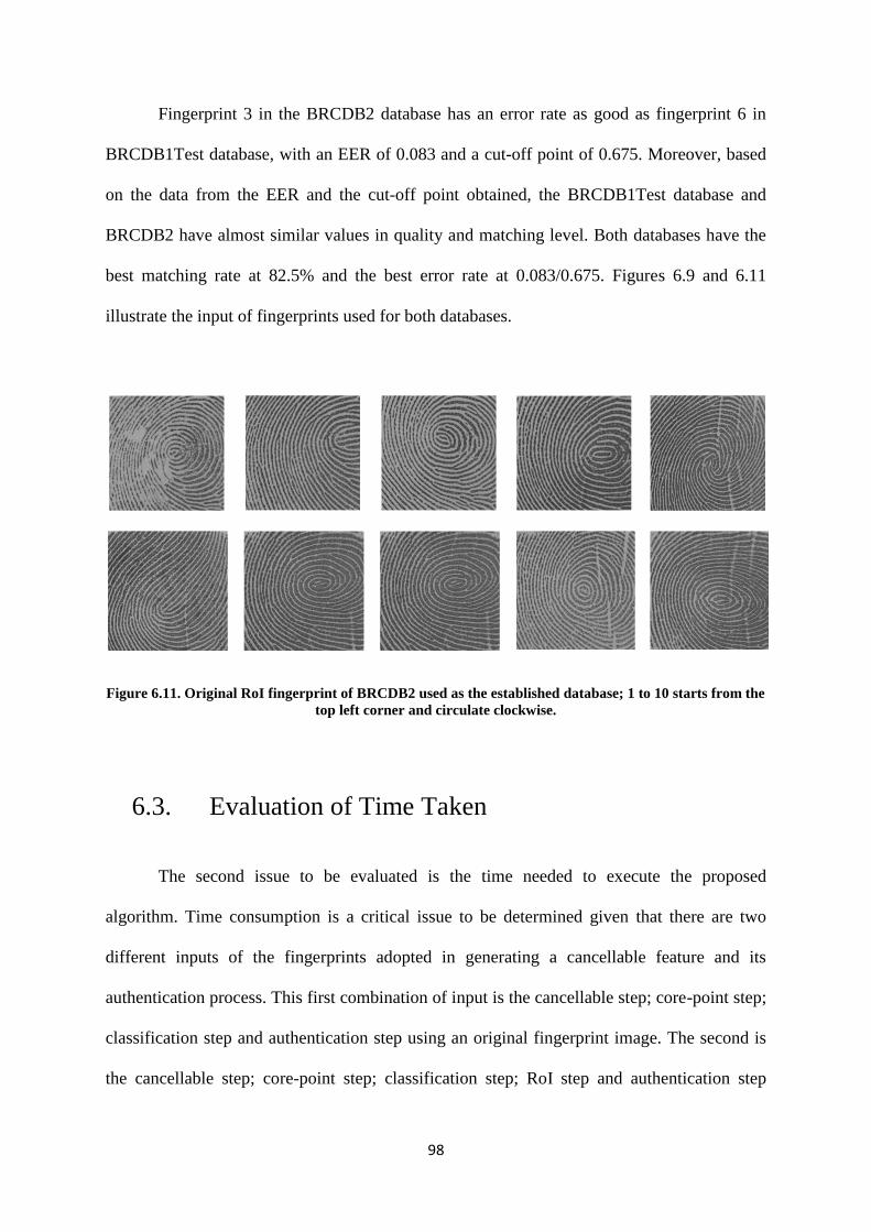
98
Fingerprint 3 in the BRCDB2 database has an error rate as good as fingerprint 6 in
BRCDB1Test database, with an EER of 0.083 and a cut-off point of 0.675. Moreover, based
on the data from the EER and the cut-off point obtained, the BRCDB1Test database and
BRCDB2 have almost similar values in quality and matching level. Both databases have the
best matching rate at 82.5% and the best error rate at 0.083/0.675. Figures 6.9 and 6.11
illustrate the input of fingerprints used for both databases.
Figure 6.11. Original RoI fingerprint of BRCDB2 used as the established database; 1 to 10 starts from the
top left corner and circulate clockwise.
6.3. Evaluation of Time Taken
The second issue to be evaluated is the time needed to execute the proposed
algorithm. Time consumption is a critical issue to be determined given that there are two
different inputs of the fingerprints adopted in generating a cancellable feature and its
authentication process. This first combination of input is the cancellable step; core-point step;
classification step and authentication step using an original fingerprint image. The second is
the cancellable step; core-point step; classification step; RoI step and authentication step
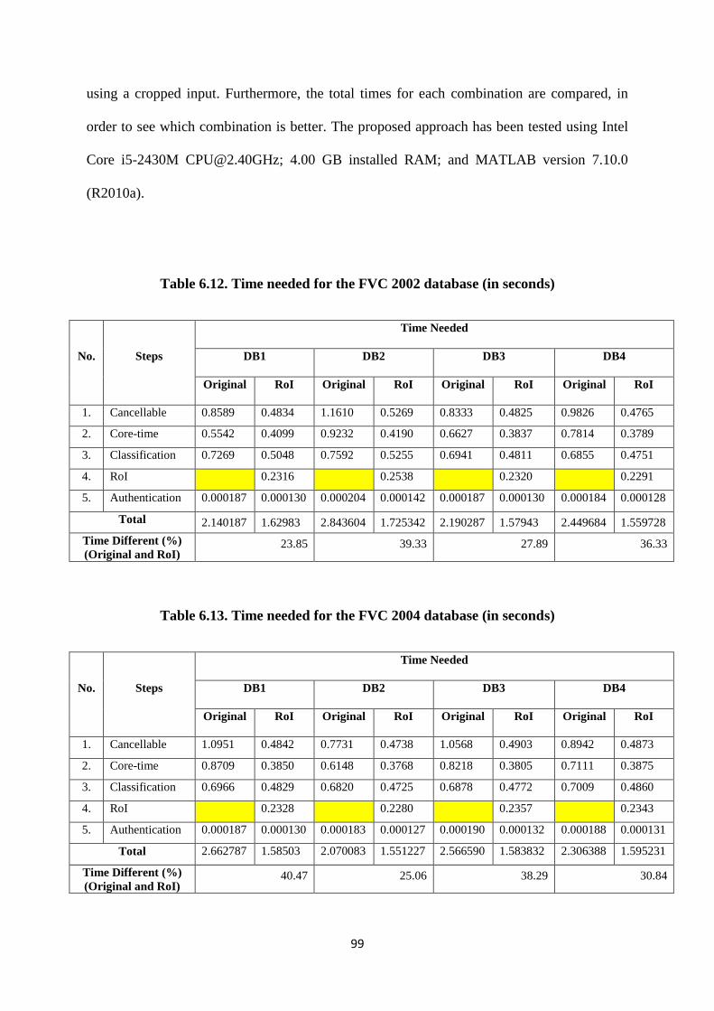
99
using a cropped input. Furthermore, the total times for each combination are compared, in
order to see which combination is better. The proposed approach has been tested using Intel
Core i5-2430M [email protected]; 4.00 GB installed RAM; and MATLAB version 7.10.0
(R2010a).
Table 6.12. Time needed for the FVC 2002 database (in seconds)
No. Steps
Time Needed
DB1 DB2 DB3 DB4
Original RoI Original RoI Original RoI Original RoI
1. Cancellable 0.8589 0.4834 1.1610 0.5269 0.8333 0.4825 0.9826 0.4765
2. Core-time 0.5542 0.4099 0.9232 0.4190 0.6627 0.3837 0.7814 0.3789
3. Classification 0.7269 0.5048 0.7592 0.5255 0.6941 0.4811 0.6855 0.4751
4. RoI 0.2316 0.2538 0.2320 0.2291
5. Authentication 0.000187 0.000130 0.000204 0.000142 0.000187 0.000130 0.000184 0.000128
Total 2.140187 1.62983 2.843604 1.725342 2.190287 1.57943 2.449684 1.559728
Time Different (%)
(Original and RoI) 23.85 39.33 27.89 36.33
Table 6.13. Time needed for the FVC 2004 database (in seconds)
No. Steps
Time Needed
DB1 DB2 DB3 DB4
Original RoI Original RoI Original RoI Original RoI
1. Cancellable 1.0951 0.4842 0.7731 0.4738 1.0568 0.4903 0.8942 0.4873
2. Core-time 0.8709 0.3850 0.6148 0.3768 0.8218 0.3805 0.7111 0.3875
3. Classification 0.6966 0.4829 0.6820 0.4725 0.6878 0.4772 0.7009 0.4860
4. RoI 0.2328 0.2280 0.2357 0.2343
5. Authentication 0.000187 0.000130 0.000183 0.000127 0.000190 0.000132 0.000188 0.000131
Total 2.662787 1.58503 2.070083 1.551227 2.566590 1.583832 2.306388 1.595231
Time Different (%)
(Original and RoI) 40.47 25.06 38.29 30.84

100
Tables 6.12 - 6.14 illustrate the time taken by the system to execute all of the research
steps. From each table, the comparison among different sub-databases in the same database is
shown to provide a different percentage between the original input and RoI input, in order to
show which input can provide more efficient use of time to run all the steps.
Table 6.14. Time needed for the BRC database (in seconds)
No. Steps
Time Needed
DB1 Test DB1 Training DB2
Original RoI Original RoI Original RoI
1. Cancellable 0.5049 0.4943 0.4762 0.4750 0.6159 0.5262
2. Core-time 0.4015 0.3931 0.3787 0.3777 0.4898 0.4184
3. Classification 0.7120 0.4929 0.6842 0.4737 0.7584 0.5247
4. RoI 0.2380 0.2287 0.2535
5. Authentication 0.000191 0.000133 0.000184 0.000128 0.000203 0.000142
Total 1.618591 1.618433 1.539284 1.555228 1.864303 1.722942
Time Different (%)
(Original and RoI) 0.0057 -1.04 7.59
Overall, it is obvious that the system using the RoI input consumes less time than an
original input except for the BRCDB1Training database, even though this system has one
more step included in the process (the RoI step). The size of the input fingerprint significantly
contributes to reducing the time taken for the procedure. Table 6.15 shows the contribution of
size differences to the time taken by the process.

101
Table 6.15. Correlation between the size differences of the input fingerprint and
time taken by the process (%)
DB1 DB2 DB3 DB4
Size Time Size Time Size Time Size Time
FVC2002 43.13 23.85 53.95 39.33 41.11 27.89 51.21 36.32
FVC2004 54.86 40.47 38.08 25.06 53.38 38.29 45.30 30.84
DB1 Test DB1 Training DB2
Size Time Size Time Size Time
BRC 1.81 0.0057 0.25 -1.04 14.04 7.59
Table 6.15 clearly shows the relationship between the size of the input fingerprint and
the time taken to complete all the processes. A larger input would require more time.
However, in this research case, it can be argued that the size difference should not be too
narrow, such as in the BRCDB1Training database, because a system that uses a fingerprint of
the RoI size needs the RoI selection step in its process. This means that it would demand
more time to execute the process. Nevertheless, Table 6.15 proves that this case is not a huge
obstacle in this research.
6.4. Evaluation of Matrices Operations Requirements
6.4.1. The Size of the Arbitrary Matrix of the KP Operation
Another parameter considered in the performance of the system is the size of the
arbitrary matrix that is used to produce a cancellable feature for the fingerprint. The reason
for this is because the size of that matrix could affect the time consumed in running the
process. Therefore, various in matrix size ware simulated to check its influence on the time
taken for the running of the process for the FVC2002, FVC2004 and BRC databases.
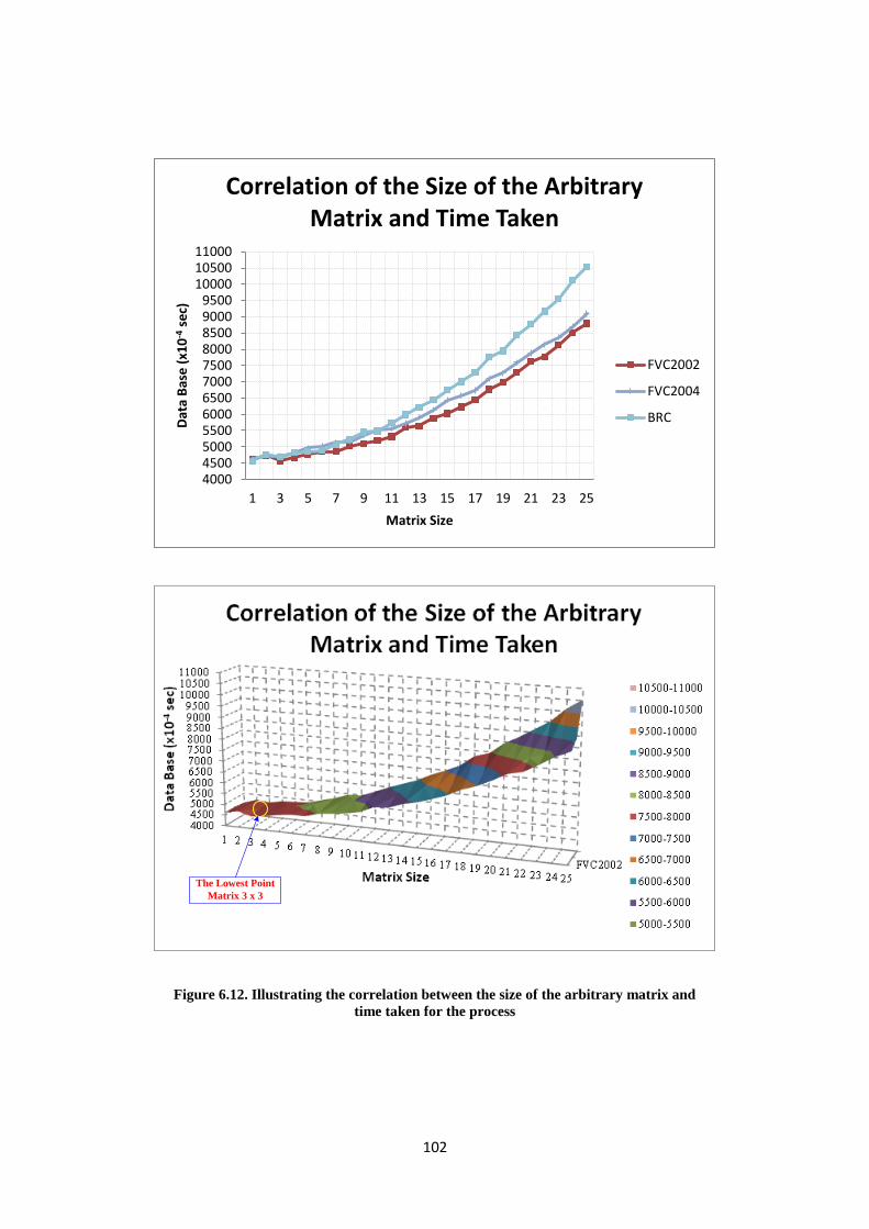
102
The Lowest Point
Matrix 3 x 3
Figure 6.12. Illustrating the correlation between the size of the arbitrary matrix and
time taken for the process
400045005000550060006500700075008000850090009500
100001050011000
1 3 5 7 9 11 13 15 17 19 21 23 25
Dat
a B
ase
(x1
0-4
se
c)
Matrix Size
Correlation of the Size of the Arbitrary Matrix and Time Taken
FVC2002
FVC2004
BRC

103
Figure 6.12 shows a simulation trend by increasing the size of the matrix started from
1 × 1 until 25 × 25 while recording the time consuming along the simulation. During the
simulation, it is established that the time taken would tend to increase, in addition to there
being a rise in the size of the matrix. However, at matrix 3 × 3, the trend tends to lower
before rising again at matrix 4 × 4. Therefore, the size of the arbitrary matrix used in this
research is matrix 3 × 3.
6.4.2. The Zero Rows and Column of ERO Operation
In the ERO operation, the most important issue to be discussed is the best number of
zero rows and columns needed to make sure that the cancellable template is safe from
impostors. The analysis is completed by undertaking several simulations involving increasing
the number of zero rows, improving the number of zero columns, and using the zero rows and
columns simultaneously, while increasing the number of zero rows and columns as well.
These simulations are performed starting from one until n/3 rows/columns, where n is the
size of the input of the fingerprint. The reason for choosing n/3 as the limit to increase the
number of rows and columns is because this would lose the detailed information of the
fingerprint feature. Figures 6.13 – 6.20 illustrate all of the simulations completed in the
research.
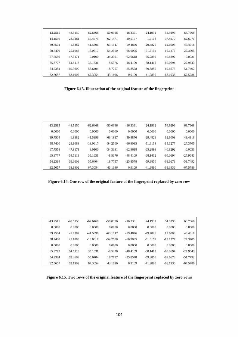
104
-13.2515 -48.5150 -62.6468 -50.0396 -16.3391 24.1932 54.9296 63.7668
14.1556 -28.0481 -57.4675 -62.1471 -40.5157 -1.9108 37.4970 62.6071
39.7504 -1.8382 -41.5896 -63.1917 -59.4876 -29.4826 12.6003 49.4918
58.7400 25.1083 -18.0617 -54.2500 -66.9095 -51.6159 -15.1277 27.3705
67.7559 47.9171 9.0100 -34.3391 -62.9618 -65.2899 -40.8292 -0.0031
65.3777 64.5113 35.1631 -8.5376 -48.4109 -68.1412 -60.0694 -27.9643
54.2384 69.3609 55.6404 18.7757 -25.8578 -59.8850 -69.6673 -51.7492
32.5657 63.1902 67.3054 43.1696 0.9109 -41.9890 -68.1936 -67.5786
Figure 6.13. Illustration of the original feature of the fingerprint
-13.2515 -48.5150 -62.6468 -50.0396 -16.3391 24.1932 54.9296 63.7668
0.0000 0.0000 0.0000 0.0000 0.0000 0.0000 0.0000 0.0000
39.7504 -1.8382 -41.5896 -63.1917 -59.4876 -29.4826 12.6003 49.4918
58.7400 25.1083 -18.0617 -54.2500 -66.9095 -51.6159 -15.1277 27.3705
67.7559 47.9171 9.0100 -34.3391 -62.9618 -65.2899 -40.8292 -0.0031
65.3777 64.5113 35.1631 -8.5376 -48.4109 -68.1412 -60.0694 -27.9643
54.2384 69.3609 55.6404 18.7757 -25.8578 -59.8850 -69.6673 -51.7492
32.5657 63.1902 67.3054 43.1696 0.9109 -41.9890 -68.1936 -67.5786
Figure 6.14. One row of the original feature of the fingerprint replaced by zero row
-13.2515 -48.5150 -62.6468 -50.0396 -16.3391 24.1932 54.9296 63.7668
0.0000 0.0000 0.0000 0.0000 0.0000 0.0000 0.0000 0.0000
39.7504 -1.8382 -41.5896 -63.1917 -59.4876 -29.4826 12.6003 49.4918
58.7400 25.1083 -18.0617 -54.2500 -66.9095 -51.6159 -15.1277 27.3705
0.0000 0.0000 0.0000 0.0000 0.0000 0.0000 0.0000 0.0000
65.3777 64.5113 35.1631 -8.5376 -48.4109 -68.1412 -60.0694 -27.9643
54.2384 69.3609 55.6404 18.7757 -25.8578 -59.8850 -69.6673 -51.7492
32.5657 63.1902 67.3054 43.1696 0.9109 -41.9890 -68.1936 -67.5786
Figure 6.15. Two rows of the original feature of the fingerprint replaced by zero rows
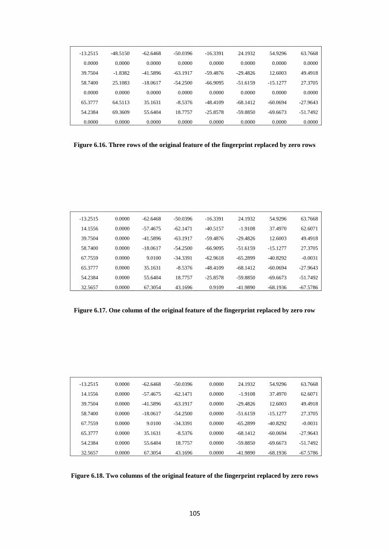
105
-13.2515 -48.5150 -62.6468 -50.0396 -16.3391 24.1932 54.9296 63.7668
0.0000 0.0000 0.0000 0.0000 0.0000 0.0000 0.0000 0.0000
39.7504 -1.8382 -41.5896 -63.1917 -59.4876 -29.4826 12.6003 49.4918
58.7400 25.1083 -18.0617 -54.2500 -66.9095 -51.6159 -15.1277 27.3705
0.0000 0.0000 0.0000 0.0000 0.0000 0.0000 0.0000 0.0000
65.3777 64.5113 35.1631 -8.5376 -48.4109 -68.1412 -60.0694 -27.9643
54.2384 69.3609 55.6404 18.7757 -25.8578 -59.8850 -69.6673 -51.7492
0.0000 0.0000 0.0000 0.0000 0.0000 0.0000 0.0000 0.0000
Figure 6.16. Three rows of the original feature of the fingerprint replaced by zero rows
-13.2515 0.0000 -62.6468 -50.0396 -16.3391 24.1932 54.9296 63.7668
14.1556 0.0000 -57.4675 -62.1471 -40.5157 -1.9108 37.4970 62.6071
39.7504 0.0000 -41.5896 -63.1917 -59.4876 -29.4826 12.6003 49.4918
58.7400 0.0000 -18.0617 -54.2500 -66.9095 -51.6159 -15.1277 27.3705
67.7559 0.0000 9.0100 -34.3391 -62.9618 -65.2899 -40.8292 -0.0031
65.3777 0.0000 35.1631 -8.5376 -48.4109 -68.1412 -60.0694 -27.9643
54.2384 0.0000 55.6404 18.7757 -25.8578 -59.8850 -69.6673 -51.7492
32.5657 0.0000 67.3054 43.1696 0.9109 -41.9890 -68.1936 -67.5786
Figure 6.17. One column of the original feature of the fingerprint replaced by zero row
-13.2515 0.0000 -62.6468 -50.0396 0.0000 24.1932 54.9296 63.7668
14.1556 0.0000 -57.4675 -62.1471 0.0000 -1.9108 37.4970 62.6071
39.7504 0.0000 -41.5896 -63.1917 0.0000 -29.4826 12.6003 49.4918
58.7400 0.0000 -18.0617 -54.2500 0.0000 -51.6159 -15.1277 27.3705
67.7559 0.0000 9.0100 -34.3391 0.0000 -65.2899 -40.8292 -0.0031
65.3777 0.0000 35.1631 -8.5376 0.0000 -68.1412 -60.0694 -27.9643
54.2384 0.0000 55.6404 18.7757 0.0000 -59.8850 -69.6673 -51.7492
32.5657 0.0000 67.3054 43.1696 0.0000 -41.9890 -68.1936 -67.5786
Figure 6.18. Two columns of the original feature of the fingerprint replaced by zero rows
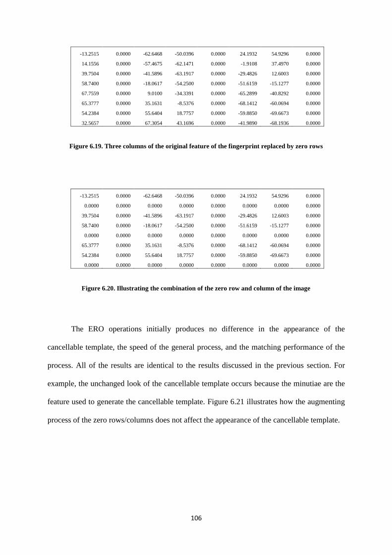
106
-13.2515 0.0000 -62.6468 -50.0396 0.0000 24.1932 54.9296 0.0000
14.1556 0.0000 -57.4675 -62.1471 0.0000 -1.9108 37.4970 0.0000
39.7504 0.0000 -41.5896 -63.1917 0.0000 -29.4826 12.6003 0.0000
58.7400 0.0000 -18.0617 -54.2500 0.0000 -51.6159 -15.1277 0.0000
67.7559 0.0000 9.0100 -34.3391 0.0000 -65.2899 -40.8292 0.0000
65.3777 0.0000 35.1631 -8.5376 0.0000 -68.1412 -60.0694 0.0000
54.2384 0.0000 55.6404 18.7757 0.0000 -59.8850 -69.6673 0.0000
32.5657 0.0000 67.3054 43.1696 0.0000 -41.9890 -68.1936 0.0000
Figure 6.19. Three columns of the original feature of the fingerprint replaced by zero rows
-13.2515 0.0000 -62.6468 -50.0396 0.0000 24.1932 54.9296 0.0000
0.0000 0.0000 0.0000 0.0000 0.0000 0.0000 0.0000 0.0000
39.7504 0.0000 -41.5896 -63.1917 0.0000 -29.4826 12.6003 0.0000
58.7400 0.0000 -18.0617 -54.2500 0.0000 -51.6159 -15.1277 0.0000
0.0000 0.0000 0.0000 0.0000 0.0000 0.0000 0.0000 0.0000
65.3777 0.0000 35.1631 -8.5376 0.0000 -68.1412 -60.0694 0.0000
54.2384 0.0000 55.6404 18.7757 0.0000 -59.8850 -69.6673 0.0000
0.0000 0.0000 0.0000 0.0000 0.0000 0.0000 0.0000 0.0000
Figure 6.20. Illustrating the combination of the zero row and column of the image
The ERO operations initially produces no difference in the appearance of the
cancellable template, the speed of the general process, and the matching performance of the
process. All of the results are identical to the results discussed in the previous section. For
example, the unchanged look of the cancellable template occurs because the minutiae are the
feature used to generate the cancellable template. Figure 6.21 illustrates how the augmenting
process of the zero rows/columns does not affect the appearance of the cancellable template.
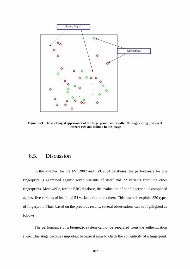
107
Figure 6.21. The unchanged appearance of the fingerprint features after the augmenting process of
the zero row and column in the image
6.5. Discussion
In this chapter, for the FVC2002 and FVC2004 databases, the performance for one
fingerprint is examined against seven variants of itself and 72 variants from the other
fingerprints. Meanwhile, for the BRC database, the evaluation of one fingerprint is completed
against five variants of itself and 54 variants from the others. This research exploits 820 types
of fingerprint. Thus, based on the previous results, several observations can be highlighted as
follows.
The performance of a biometric system cannot be separated from the authentication
stage. This stage becomes important because it aims to check the authenticity of a fingerprint.
108
Therefore, the system can decide which input of the fingerprint should be either accepted
(genuine) or rejected (impostor). However, it has become commonplace in the authentication
step that not all the accepted or rejected fingerprints are true genuine cases and true
impostors. These conditions are known as false genuines and false impostors. A false
genuine and impostor would create a problem if the corresponding rates (EERs) are very
large. Hence, the fingerprint with the lowest EER has a chance of becoming a better
fingerprint in the database. However, the EER is not the only requirement to acknowledge
which fingerprint has a superior error rate. In this research, the threshold value is also
determined as a parameter to understand which fingerprint in the same database has the
lowest error rate. The reason for this is because the cut off value would show an exemption
level for the authentication system to decide on the authenticity of the fingerprint.
Finding an error rate for each fingerprint in the database is required to discover the
characteristics of the database when the proposed algorithm is applied. Tables 6.1 - 6.8 show
that the lowest level error rate for the FVC2002 and FVC2004 databases is 0.063.
Meanwhile, the highest EER and the threshold of each EER could be dissimilar. In terms of
the threshold score, the highest score would represent the better condition of the fingerprint.
If a fingerprint has a high cut off score, it means that the enquiry fingerprint would be
recognized by the system as an authorized fingerprint even with a high qualification matching
score. However, the cut off rate does not become a priority in deciding which fingerprint has
a better error rate; however, the EER with the lowest score does. For example, in the
FVC2002DB2 database, fingerprint 4 has an improved error rate with an EER score of 0.063
and a 0.475 cut off score; compared with the other fingerprints. Notwithstanding this,
fingerprint 108 has the highest threshold score of 0.525. Similarly, fingerprint 107 in the
FVC2002DB3 database has a better error rate with an EER score of 0.063 and a threshold
109
score of 0.375. However, fingerprint 108 has a threshold score of 0.525 which is 40% higher
than that of fingerprint 107.
Obviously, the FVC2002 (DB1, DB2, DB3, DB4), FVC2004 (DB1, DB2, DB3,
DB4), and BRC (DB1Test, DB1Training, DB2) databases use different scanners to obtain
fingerprint images. Based on the EER score, the threshold score, and the type of scanner used
to acquire the fingerprint, it is apparent that the clarity of the input of fingerprints plays an
important role in minimizing the error rate. In other words, the quality of the fingerprint
influences how many fingerprints would be classified as genuine owners or impostors and
how minimal the error rate is. For example, the highest threshold score for FVC2002DB1;
DB2; DB3; DB4, FVC2004DB1; DB2; DB3; DB4, BRCDB1Test; Training and DB2
databases are 0.475, 0.525, 0.525, 0.425, 0.525, 0.175, 0.275, 0.375, 0.825, 0.625, and 0.825
respectively. Referring to these scores, it can be seen that the scores for the BRC databases
are better than the other databases since their fingerprints are better image quality.
In order to evaluate the time taken in executing the algorithm, this research offers two
possible types of input for the fingerprint. The first type is through using the original
fingerprint as an input, while the second type is by selecting a particular area of the original
fingerprint to reduce any unneeded features captured by the algorithm process. The latter type
requires an additional step, specifically the RoI selection process, to select a desired area of
the fingerprint. It is obvious that an extra step would require additional time to complete the
algorithm. However, in this research, the size of the input of the fingerprint plays an
important role in reducing the time consumed. For example, Tables 6.12 - 6.14 compare the
two types of fingerprints. The additional step of the process does not affect the total time
taken for execution. In Table 6.15, it is clearly seen that the reduction in size results in less
time taken except for the BRCDB1 Training database. The latter case occurred because the

110
size difference between the original input and the RoI input is only 0.25%, and therefore, the
time required for the RoI input is 1.04% more than the original input.
Furthermore, the discussion with regards to some of the prerequisite for the matrices
operations should not be a part of these two following cases, such as the size of the arbitrary
matrix that is used in the KP operation; and the number and placing of the zero rows or
columns on the fingerprint matrix in the ERO operation. In relation to the former one, it
should not be a part of the time needed either if the size of the arbitrary matrix is large or
small. Figure 6.12 clearly shows that the time consumed by the process would increase when
the size of the arbitrary matrix is enlarged. However, at the point at which the size of the
matrix is 3 x 3; the taken time is reduce slightly by approximately 3.68% for the FVC2002,
0.0339% for the FVC2004, and 1.54% for the BRC databases. Meanwhile, Figures 6.13 to
6.20 illustrate the zero rows and columns, and the replaced rows and columns of the feature
of the fingerprint. Initially, these procedures do not have an impact on the results at all. The
appearance of the template of the cancellable fingerprint is still the same as in the figures
shown in the two previous chapters, as long as the numbers of zero rows or columns are not
more than a third of the size of the rows/columns of the original matrix. Likewise, the speed
and matching performance of the process are no different.
6.6. Summary
The aim of this chapter has been to evaluate the performance of the proposals
discussed in the two previous chapters. Hence, three kinds of evaluation of error rates, time
taken and matrices operations requirements are performed to check the performance with the
eleven different databases of the fingerprint. One of the evaluations shows that each database

111
has its own characteristics depending on the type of fingerprint acquired from the database
scanner. If the fingerprint scanner produces a fingerprint with a good qualification, the error
rate and the threshold of the database can be reliable.
Furthermore, the time consumed by the execution process depends on the size of the
input of the fingerprint. The time taken would be reduced if the size is smaller. Subsequently,
for a small input fingerprint, even though the RoI step would be added to the algorithm, the
total time used for the process would not significantly change with the proviso that the size
reduction of the input is not too slight.
Meanwhile, regarding the implementation of the matrices operations, this procedure
does not change the results for or the characteristics of the cancellable template, as long as
the requirements of the matrices operations are not excessive.

112
Chapter 7
7. Conclusion and Future Work
This chapter summarises the main aspects of the research work undertaken in
generating the template for a cancellable fingerprint. The main contributions planned and
targeted in Chapter 1 have been completed and are summarized. Nonetheless, there is still
additional research that needs to be conducted in the future. Hence, recommendations are
made as guidance to implementing this approach with other applications and to increase the
efficiency and quality of the cancellable template. Overall, however, the work described in
this thesis has satisfied the aims and objectives mentioned in Chapter 1.
7.1. Conclusion
Establishing a cancellable template for a biometric technology such as fingerprint
technology is a considerable challenge, especially related to the reissuing ability, multi-
application implementation and dependablity. The implementation of several matrix
operations and requirements for several fingerprint algorithms becomes a continuous work to
complete these three important issues. Matrix applications such as the KP operation, ERO
operation and Inverse operation can be used as a solution to solve the first two issues.
Meanwhile, a sequence of steps of fingerprint enhancement, core-point identification, region
of interest, fingerprint classification, and minutiae extraction processes can be utilized to
resolve the third issue. In Chapter 1, these issues have been discussed as a challenge to be
113
taken on and overcome. As documented in this thesis, the aims and objectives have been
fulfilled by the present research.
A novel approach is proposed to produce a cancellable fingerprint template exploiting
several matrices operations. The KP, ERO and Inverse operations are implemented in the
algorithm to obtain a reliable cancellable template. This new idea is based on the principle of
achieving a non-invertible matrix. A matrix cannot be inverted as long as the matrix
possesses certain criteria, having at least one zero row/column, having a non-square form,
and having a row that is a multiple of another row.
The three matrix operations need an appropriate procedure in order to satisfy these
three requirements. The KP operation is a procedure used to enlarge the size of an input by
taking the tensor product of it with an arbitrary matrix, which will then change the value of
each pixel of the original input. This procedure can disguise the appearance of the fingerprint
since the original element of the fingerprint has been replaces. ERO provides a procedure to
perform several matrix operations, such as rotating, conversing, multiplying and changing
each element of the matrix. Meanwhile, the inverse operation could transform a matrix into
one with a different value. Three different orders of matrix operations have been introduced
to analyze which can provide an improved method to produce a high-quality cancellable
template, which are Inverse-KP-ERO procedure; KP-Inverse-ERO procedure; and Inverse-
KP procedure. Based on the research results, the first procedure is more secure in terms of
protecting the template to be inverted, so as to find the original source of the fingerprint.
In terms of producing a dependable cancellable template, several fingerprint
processing steps are implemented by exploiting eleven different databases of fingerprints,
FVC2002DB1; DB2; DB3; DB4, FVC2004DB1; DB2; DB3; DB4, BRCDB1Test; Training;
DB2. The first process is fingerprint enhancement. This is needed so as to produce a clear
114
input for all fingerprint processes. For example, an enhanced image of a fingerprint is very
helpful in identifying the correct core-point and avoiding a false core-point detection and
false minutiae extraction. Moreover, a noise-free input fingerprint is useful in avoiding
carrying over unimportant pixels into the cancellable fingerprint template. In this research,
the core-point detection approach is appropriate not only for one type of database, but can
also be implemented with different types of databases. This improvement is achieved if the
input is an enhanced image. Otherwise, if a poor quality image becomes the input, the
proposed approach detects a false core-point. Given that the core-point is also utilized in the
RoI and fingerprint classification steps, this result has an impact in yielding a progressive
result.
A novel approach is proposed to select a particular area in the RoI step to
accommodate the needs of a square input form for a cancellable fingerprint and the need to
omit unimportant areas for the minutiae extraction step. Even though the RoI stage reduces
the area of the fingerprint; this step is required to discard noise evident in the fingerprint
image. In the classification of the fingerprint image, there are three requirements: the core
point and its number, ridge frequency, and ridge direction; whilst the TA is only an additional
requirement. In this thesis, for the FVC2002 database, only 51.25% out of 320 fingerprint
images are classified. The false classifications happen because the fingerprints do not meet
some of the required criteria.
Finally, a short ridge-line after the core and false-core identification can lead to false
classifications in all classes. For likely left/right loop classes especially, this decision is based
on the core position and upper- and lower-ridge furrow form and direction. Furthermore, for
FVC2004, the percentage of classified fingerprints is slightly higher than for FVC2002. This
is because the fingerprint input size in FVC2004 is bigger, so that fingerprint details like the
core and TA are better covered than in FVC2002. Nevertheless, as the acquisition quality of
115
FVC2004 is lower, so then the percentage of false classifications in FVC2004 is higher than
in FVC2002. Meanwhile, in the BRC DBI-Test case, as the size of the fingerprints are
smaller than in the two previous databases detailed information to classify the fingerprint
core, TA and enough ridge length after the core is not provided. This causes the percentages
of false classifications and unclassified fingerprints to be higher than with the two other
databases.
The performance for one fingerprint from databases FVC2002 and FVC2004 was
examined against seven variants of itself and 72 variants from other fingerprints. This means
that eighty fingerprints were assessed in total. One is used in the database as an authorized
fingerprint. Meanwhile, for the BRC database, the evaluation of one fingerprint was
performed against five variants of itself and 54 variants from the others. Thus, this research
exploits 820 types of fingerprints.
In this thesis, the performance of a biometric system cannot be considered separately
from the authentication stage. This stage is important because it checks the authenticity of a
fingerprint. Subsequently, the system can decide which input of a fingerprint should be either
accepted (genuine) or rejected (impostor). However, it has become commonplace during
authentication that not all the accepted or rejected fingerprints are true genuines and true
impostors. These conditions are known as false genuines and false impostors, which create a
problem if their rates (EER) are very high. Hence, the fingerprint with the lowest EER has a
chance of becoming a better fingerprint in the database. However, the EER is not the only
requirement in acknowledging which fingerprint has a better error rate.
In this research, the cut-off point value is also determined as a parameter to recognize
which fingerprint in the same database has the lowest error rate. This is because the cut-off
point value shows an exemption for the authentication system to decide the authenticity of the

116
fingerprint. Finding an error rate for each fingerprint in the database is required to discover
the characteristics of the database after the proposed algorithm is applied to it. Based on the
experiment conducted, the lowest error rate level for databases FVC2002 and FVC2004 is
0.063. Meanwhile, the highest EER and the cut off value for each EER could be dissimilar.
In terms of the cut-off point score, the highest score would represent the better
condition of the fingerprint. If a fingerprint has a high cut-off point, it means that the enquiry
fingerprint would be recognized by the system as an authorized fingerprint, even with a high
qualification matching score. However, the threshold rate does not become a priority in
deciding which fingerprint has a better error rate; however, the EER with the lowest score
does. Obviously, databases FVC2002 (DB1, DB2, DB3, DB4), FVC2004 (DB1, DB2, DB3,
DB4), and BRC (DB1Test, DB1Training, DB2) use different scanners to obtain the
fingerprint images. Based on the EER score, the cut-off point score, and the type of scanner
used to acquire the fingerprint, it is obvious that the clarity of the input of a fingerprint plays
an important role in minimising the error rate. In other words, the quality of fingerprints
influences how many would be classified as belonging to an impostor and how minimal the
error rate is.
In terms of evaluating the time taken to execute the algorithm, this research has
undertaken the evaluation by offering two possible types of input for the fingerprint. The first
is the use of the original fingerprint as an input, and the second involves selecting a particular
area of the original fingerprint to remove any unneeded features captured during the
algorithm process. The latter type requires an additional step, namely the RoI selection
process, to select a desired area of the fingerprint.
It is obvious that an extra step would require additional time taken to complete the
algorithm. However, in this research, the size of the input of the fingerprint plays an
117
important role in reducing the length of time that it takes. In fact, the additional step of this
process does not affect the total time taken for execution, except for database BRCDB1
Training. Furthermore, the time consuming by the process would increase when the size of
the arbitrary matrix is enlarged as well. Meanwhile, initially, the zero rows/columns
procedures do not have an impact on the cancellable results at all. The cancellable fingerprint
template still appears the same as long as the numbers of zero rows or columns are no more
than a third of the size of the rows/columns of the original matrix. Similarly, the speed and
matching performances of the process are no different.
To conclude, this thesis has presented an alternative approach to producing a
cancellable template of a fingerprint. Several supporting requirements are also introduced to
standardize the procedure, in order to complete this new cancellable approach. This approach
has an advantage which is not possessed by other cancellable algorithms in that it can be
implemented with other biometric technologies. Furthermore, the comparison among all
databases shows that the BRC databases show better qualification in term of error rates and
the cut off level.
7.2. Recommendations for Future Work
Based on the research presented in this thesis, there are other possibilities for further
research investigation, which should be initiated as follows.
- A challenge for future work will be to implement all of the proposed algorithms and
procedures into a different biometric technology. However, it is obvious that other
biometric technologies will need different procedures during execution, which will
need to be carefully specified.

118
- In this thesis, the RoI procedures are required because the cancellable algorithm needs
a square image. In addition, it is unavoidable that this procedure removes a fraction of
the original fingerprint. This means that some information related to the feature of the
fingerprint is lost. Therefore, in future work, acquiring a square shape without
diminishing the whole surface of the fingerprint needs to be considered by selecting
and adjusting the RoI input, rather than by decreasing area of the original image.
- The proposed RoI procedure assigns the core-point as a reference point to select the
desired region of the fingerprint. The procedure does not position the core at the
centre of the selection area, based on the fact that no fingerprint in any database has
its core-point precisely at the centre of the fingerprint. Therefore, in the future work, it
is quite important to position the core in the middle of the RoI, and thus the selected
RoI would cover the entire surface of the fingerprint.
119
References
[1] A. Ross, S. Dass, and A.K. Jain, “A Deformable Model for Fingerprint Matching,”
Journal of Pattern Recognition, Elsevier, vol. 38, no. 1, pp. 95-113, Jan. 2005.
[2] T. Matsumoto, H. Matsumoto, K. Yamada, and S. Hoshino, “Impact of Artificial
Gummy Fingers on Fingerprint Systems”, In Proc. of SPIE, Optical Security and
Counterfeit Deterrence Technique IV, vol. 4677, pp. 275-289, Feb. 2002.
[3] A.K. Jain, A. Ross, and S. Pankanti, “Biometric: A Tool for Information Security”,
IEEE Trans. Information Forensics and Security, vol. 1, no. 2, pp. 125-144, Jun.
2006.
[4] J. K. Schneider, “Ultrasonic Fingerprint Sensors”, Advances in Biometrics, Springer,
pp. 63-74, 2008.
[5] H. C. A. van Tilbong and S. Jajodia, “Encyclopedia of Cryptography and Security”,
Second Edition, Springer Reference, p. 463, 2011.
[6] R. Cappelli, D. Maio, D. Maltoni, J. L. Wayman, and A.K. Jain, “Performance
Evaluation of fingerprint Verification Systems,” IEEE Trans. Pattern Anal. Mach.
Intell., vol. 28, no. 1, pp. 3-18, Jan. 2006.
[7] A.K. Jain, L. Hong, and R. Bolle, “On-Line Fingerprint Verification,” IEEE
Transactions on Pattern Recognition and Machines Intelligence, vol. 19, no. 4, pp.
302-314, Aug, 1996.
120
[8] L. Hong and A.K. Jain, “Integrating Faces and Fingerprints for Personal
Identification,” IEEE Trans. Pattern Anal. Mach. Intell., vol. 20, no. 12, pp. 1295-
1307, Dec. 1998.
[9] A.K. Jain, A. Ross, and S. Prabhakar, “An Introduction to Biometric Recognition,”
IEEE Trans. Circuits Syst. Video Technology, Special Issue Image- and Video-Based
Biomet., vol. 14, no. 1, pp. 4-20, Jan. 2004.
[10] S. Prabhakar, S. Pankanti, and A.K. Jain, “Biometric Recognition: Security and
Privacy Concerns,” IEEE Security Privacy, vol. 1, no. 2, pp. 33-42, 2003.
[11] N. Ratha, J.H. Connell, and R.M. Bolle, “An Analysis of Minutiae Matching
Strength,” In Proc. Int. Conf. Audio- Video- Based Biometric Person Authentication,
pp. 223-228, Halmstad, Sweden, 2001.
[12] U. Uludag, S. Pankanti, S. Prabhakar, A.K. Jain, “Biometric Cryptosystems: Issues
and Challenges,” in Proc. of The IEEE, Vol. 92, No. 6, pp. 948-960, June 2004.
[13] C. Vielhauer, R. Steinmetz, “Handwriting: Feature Correlation Analysis for Biometric
Hashes,” EURASIP Journal on Applied Signal Processing, Vol. 4, pp. 542-558, 2004.
[14] N. Ratha, J. Connel, and R. Bolle, “Enhancing Security and Privacy in Biometric-
Based Authentication System,” IBM Systems Journal, vol. 40, no. 3, pp. 614-634,
2001.
[15] R.M. Bolle, J.H. Connell, and N.K. Ratha, “Biometric perils and Patches,” Pattern
Recognition, vol. 35, no. 12, pp. 2727-2738, 2002.
[16] B. Schneier, “Biometrics: Uses and Abuses,” Communications of the ACM, vol. 42,
no. 8. page 1, 1999.
[17] D. Maltoni, D. Maio, A.K. Jain, and S. Prabhakar, “Handbook of Fingerprint
Recognition,” New York: Springer-Verlag, 2003.
121
[18] T. Boult, “Robust Distance Measures for Face-Recognition Supporting Revocable
Biometric Token,” In Proc. 7th
Int. Conf. Autom. Face and Gesture Recog., pp. 560-
566, Southampton, U.K., Apr. 10-12, 2006.
[19] A. Ross and R. Govindarajan, “Feature Level Fusion Using Hand and Face
Biometrics,” In Proc. Of SPIE Conf. Biometric Technology for Human Identification
II, pp. 196-204, Mar. 2005.
[20] S.Z. Li and A.K. Jain, Eds., “Handbook of Face Recognition,” New York: Springer
Verlag, 2004.
[21] F. Cardinaux, C. Sanderson, and S. Bengio, “User Authentication via Adapted
Statistical Models of Face Images,” IEEE Transaction on Signal Processing, vol. 54,
no. 1, pp. 361-373, Jan. 2006.
[22] P. Campisi, E. Maiorana, and A. Neri, “On-line Signature Based Authentication:
Template Security Issues and Countermeasures,” In N.V. Boulgouris, K.N.
Plataniotis, & E. Micheli-Tzanakou (Eds.), Biometrics: Theory, Methods, and
Applications. Wiley/IEEE, 2008.
[23] D. Bhattacharyya, S.K. Bandopadhaya, P. Das, D. Ganguly, and S. Mukherjee,
“Statistical Approach for Offline Handwritten Signature Verification,” Journal of
Computer Science, Science Publication, vol. 4, no. 3, pp. 181-185, May. 2008.
[24] S. Kanade, D. Petrovska-Delacretaz, and B. Dorizzi, “Cancellable Iris Biometrics and
Using Error Correcting Codes to Reduce Variability in Biometric Data,” In Proc. of
IEEE Conference on Computer Vision and Pattern Recognition(CVPR), pp. 120-127,
2009.
[25] S.R. Ganorkar, A.A. Ghatol, “Iris Recognition: An Emerging Biometric Technology,”
In Proc. Of the 6th
WSEAS International Conference on Signal Processing, Robotics
and Automation, pp. 91-96, Greece, Feb. 2007.
122
[26] J.L. Wayman, A.K. Jain, D. Maltoni, and D. Maio, Eds., “Biometric Systems:
Technology, Design and Performance Evaluation,” New York: Springer Verlag, 2005.
[27] J.G. Daugman, “The Importance of Being Random: Statistical Principles of Iris
Recognition,” Journal of Pattern Recognition, Elsevier, vol. 36, no. 2, pp. 279-291,
Feb. 2003.
[28] W. Xu and M. Cheng, “Cancellable Voiceprint Template Based on Chaff-Points-
Mixture Method,” In Proc. of International Conference on Computational
Intelligence and Security, pp. 263-266, 2008.
[29] S. Furui, “Recent Advances in Speaker Recognition,” In Proc. of International
Conference on Audio and Video Based Biometric Person Authentication, pp. 859-872,
UK, Mar. 1997.
[30] N.K. Ratha, S. Chikkerur, J.H. Connell, and R.M. Bolle, “Generating Cancellable
Fingerprint Templates,” IEEE Trans. on Pattern Analysis and Machine Intelligence,
vol. 29, no. 4, pp. 561-572, 2007.
[31] A. Nagar and A.K. Jain, “On the Security on Non-Invertible Fingerprint Template
Transformed,” IEEE Workshop on Information Forensics and Security (WIFS),
London, Dec. 2009.
[32] C. Lee and J. Kim, “Cancellable Fingerprint Templates using Minutiae-Based Bit-
Strings,” J Network Comp. Appl., 2010, doi:10.1016/j.jnca.2009.12.011.
[33] C. Lee, J. Choi, K. Toh, S. Lee, and J. Kim, “Alignment-Free Cancellable Fingerprint
Templates Based on Local Minutiae Information,” IEEE Trans. on Systems Man. And
Cybernetics-B, vol. 37, pp. 980-992, 2007.
[34] F. Farooq, R.M. Bolle, T.Y. Jea, and N. Ratha, “Anonymous and Revocable
Fingerprint Recognition,” In Proc. Computer Vision and Pattern Recognition,
Minneapolis, June, 2007.
123
[35] S. Chikkerur, N.K. Ratha, H. Connell, and R.M. Bolle, “Generating Registration-Free
Cancellable Fingerprint Templates,” In BTAS08, pp. 1-6, 2008.
[36] J. Bringer, H. Chabanne, B. Kindarji, “The Best of Both Worlds: Applying Secure
Sketches to Cancellable Biometrics,” Science of Computer Programming, vol. 74, no.
1-2, pp. 43-51, 2008.
[37] B. Yang, C. Busch, M. Derawi, P. Bours, and D. Gafurov, “Geometric-Aligned
Cancellable Fingerprint Templates,” In Proc. of the 15th
Int. Conf. on Image Analysis
and Processing, LNCS, Vol. 5716, pp. 490-499, Vietrisul Mare, Italy, Sept. 08-11,
2009.
[38] F. Quan, S. Fei, C. Anni, and Z. Feifei, “Cracking Cancellable Fingerprint Template
of Ratha,” In International Symposium on Computer Science and Computational
Technology (ISCSCT ’08), vol. 2, pp. 572-575, 2008.
[39] S.W. Shin, M.-K. Lee, D.S. Moon, and K.Y. Moon, “Dictionary Attack on Functional
Transform-Based Cancellable Fingerprint Templates,” ETRI Journal, vol. 31, no. 5,
pp. 628-630, 2009.
[40] S. Tulyakov, F. Farooq, and V. Govindaraju, “Symmetric Hash Functions for
Fingerprint Minutiae,” In International Workshop on Pattern Recognition for Crime
Prevention, Security, and Surveillance (ICAPR ’05), vol. 3687, pp. 30-38, 2005.
[41] R. Ang, R. Safavi-Naini, and L. Mc. Aven, “Cancellable Key-Based Fingerprint
Templates,” In Proc. of Information Security and Privacy: 10th
Australasian
Conference (ACISP ’05), pp. 242-252, 2005.
[42] A.T.B. Jin and L.M. Hui, “Cancellable Biometrics,” Scholarpedia, vol. 5, no. 1, page
9201, 2010. doi: 10.4249/scholarpedia.9201.
[43] M. Kuhn, R. Anderson, J. Daugman, “Tamper Resistance: A Cautionary Note,”
Workshop on Electronic Commerce. 1996.

124
[44] H. Anton, C. Rorres, “Elementary Linear Algebra, Application Version: Ninth
Edition,” Wiley eGrade, 2005.
[45] A.J. Laub, “Matrix Analysis for Scientists and Engineers,” The Society for Industrial
and Applied Mathematics, pp. 139-142, 2005.
[46] H. Fronthaler, K. Kollreider, and J. Bigun, “Local Features for Enhancement and
Minutiae Extraction in Fingerprints”, IEEE Transaction on Image Processing, vol. 17,
no. 3, pp. 354-363, March. 2008.
[47] L. Hong, Y. Wan, and A.K. Jain, “Fingerprint Image Enhancement: Algorithm and
Performance Evaluation”, IEEE Transactions on Pattern Analysis and Machine
Intelligence, vol. 20, no. 8, pp. 777-789, 1998.
[48] S. Prabhakar, A.K. Jain, J. Wang, S. Pankanti, and R. Bolle, “Minutiae Verification
and Classification for Fingerprint Matching”, In Proceeding of 15th
International
Conference Pattern Recognition (ICPR), vol. 1, pp. 25-29, September 2000.
[49] A. Ross, A.K. Jain, and J. Reisman, “A Hybrid Fingerprint Matcher”, Pattern
Recognition, vol. 36, no. 11, pp. 1657-1672, 1995.
[50] A.K. Jain, S. Prabhakar, and L. Hong, “A Multichannel Approach to Fingerprint
Classification”, IEEE Transactions on Pattern Analysis and Machine Intelligence,
vol. 21, no. 4, pp. 348-359, 1999.
[51] J.G Daugman, “Uncertainty Relation for Resolution in Space, Spatial Frequency, and
Orientation Optimized by Two-Dimensional Visual Cortical Filters”, In Journal of the
Optical Society of America (A), vol. 2, no. 7, pp. 1160-1169, July 1985.
[52] D.B.G. Sherlock, D.M. Monro, and K. Millard, “Fingerprint Enhancement by
Directional Fourier Filtering”, In IEE Proc. Vis. Image Signal Processing, vol. 141,
pp. 87-94, 1994.
125
[53] N.K. Ratha, S. Chen, and A.K. Jain, “Adaptive Flow Orientation-Based Feature
Extraction in Fingerprint Images”, Pattern Recognition, vol. 28, no. 11, pp. 1657-
1672, 1995.
[54] A.M. Basen and S.H. Gerez, “Systematic Methods for the Computation of the
Directional Fields and Singular Points of Fingerprints”, IEEE Transactions on Pattern
Analysis and Machine Intelligence, vol. 24, no. 7, pp. 905-919, 2002.
[55] M. Kass and A. Witkin, “Analyzing Oriented Patterns”, Computer Vision, Graphics,
and Image Processing, vol. 37, no. 3, pp. 362-385, 1987.
[56] J. Bigun and G.H. Granlund, “Optimal Orientation Detection of Linear Symmetry”, In
Proc. First International Conference on Computer Vision, pp. 433-438, 1987.
[57] R.C. Gonzalez and R.E. Woods, “Digital Image Processing (Third Edition)”, Prentice
Hall, 2007.
[58] L. O’Gorman and J.V. Nickerson, “An Approach to Fingerprint Filter Design”,
Pattern Recognition, vol. 22, no. 1, pp. 29-38, 1989.
[59] M. Liu, X. Jian, and A.C. Kot, “Fingerprint Reference-Point Detection”, EURASIP
Journal on Advances in Signal Processing, vol. 2005, no. 4, pp. 498-509, 2005.
[60] M.A. Oliveira and N.J. Leite, “A Multiscale Directional Operator and Morphological
Tools for Reconnecting Broken Ridges in Fingerprint Images”, Pattern Recognition,
vol. 41, no. 1, pp. 367-377, 2008.
[61] P. Lo, “Method and Apparatus for Adaptive Hierarchical Processing of Print Images”,
US Patent Application Publication No. 2007/0292005A1, 2007.
[62] T. Kamei and M. Mizoguchi, “Image Filter Design for Fingerprint Enhancement”, In
Proceeding of International Symposium on Computer Vision, pp. 109-114, November,
1995.
126
[63] S.C. Dass, “Markov Random Field Models for Directional Field and Singularity
Extraction in Fingerprint Images”, IEEE Transactions on Image Processing, vol. 13,
no. 10, pp. 1358-1367, 2004.
[64] K.C. Lee and S. Prabhakar, “Probabilistic Orientation Field Estimation for Fingerprint
Enhancement and Verification”, In Proc. Biometrics Symposium (BSYM), pp. 41-46,
September 2008.
[65] S.Z. Li, “Markov Random Field Modeling in Image Analysis (Third Edition),
Springer, 2009.
[66] A. Blake, P. Kohli, and C. Rother, Eds., “Markov Random Fields for Vision and
Image Processing”, MIT Press, 2011.
[67] J. Gu, J. Zhou, and C. Yang, “Fingerprint Recognition by Combining Global Structure
and Local Cues”, IEEE Transactions on Image Processing, vol. 15, no. 7, pp.
19521964, 2006.
[68] Y. Wang, J. Hu, and D. Phillips, “A Fingerprint Orientation Model Based on 2D
Fourier Expansion (FOMFE) and Its Application to Singular-Point Detection and
Fingerprint Indexing”, IEEE Transactions on Pattern Analysis and Machine
Intelligence, vol. 29, no. 4, pp. 573-585, 2007.
[69] B.G. Sherlock and D.M. Monro, “A Model for Interpreting Fingerprint Topology”,
Pattern Recognition, vol. 26, no. 7, pp. 1047-1055, 1993.
[70] J. Zhou and J. Gu, “A Model-Based Method for the Computation of Fingerprints’
Orientation Field”, IEEE Transactions on Image Processing, vol. 13, no. 6, pp. 821-
835, 2004.
[71] S. Huckemann, T. Hotz, and A. Munk, “Global Models for the orientation Field of
Fingerprints: An Approach Based on Quadratic Differentials”, IEEE Transactions on
Pattern Analysis and Machine Intelligence, vol. 30, no. 9, pp. 1507-1519, 2008.

127
[72] S. Yoon, J. Feng, and A.K. Jain, “On Latent Fingerprint Enhancement”, In SPIE
Biometric Technology for Human Identification VII, vol. 7667, no. 1, pp. 766-707,
2010.
[73] A. Julasayvake and S. Choomchuay, "An Algorithm for Fingerprint Core Point
Detection", International Symposium on Signal Processing and Its Applications, pp.
1-4, 2007.
[74] N.K. Johal and A. Kamra, “A Novel Method for Fingerprint Core Point Detection”,
International Journal of Scientific and Engineering Research, vol. 2, issue. 4, April,
2011.
[75] K. Nilsson and J. Bigun, “Localization of Corresponding Points in Fingerprints by
Complex Filtering”, Pattern Recognition Letters, vol. 24, pp. 2135-2144, 2003.
[76] C.H. Park, J.J. Lee, M.J.T. Smith, S.I. Park, and K.H. Park, “Directional Filter Bank-
Based Fingerprint Feature Extraction and Matching”, IEEE Transactions on Circuits
and Systems for Video Technology, vol. 14, no. 1, pp. 74-85, January 2004.
[77] P. Kapsalas, K. Rapantzikos, A. Sofou, and Y. Avrithis, “Regions of Interest for
Accurate Object Detection”, in Proc. Of Sixth International Workshop on Content-
Based Multimedia Indexing (CBMI 2008), pp.147-154, June 2008.
[78] F. Galton, “Fingerprints”, McMillan, London, 1893.
[79] E. Henry, “Classification and Uses of Finger Prints”, Routledge, London, 1900.
[80] G.T. Candela, P.J. Grother, C.I. Watson, R.A. Wilkinson, C.L. Wilson, “PCASYS –
A Pattern-Level Classification Automation System for Fingerprints”, Technique
Report, NIST TR 5647, 1995.
[81] K. Karu and A.K. Jain, “Fingerprint Classification”, Pattern Recognition, vol. 29, no.
3, pp. 389-404, 1996.
128
[82] C.H. Park and H. Park, “Fingerprint Classification using Fast Fourier Transform and
Non-Linear Discriminant Analysis”, Pattern Recognition, vol. 38, no. 4, pp. 495-505,
2005.
[83] A. Senior, “A Combination Fingerprint Classifier”, IEEE Transaction of Pattern
Analysis and Machine Intelligence, vol. 23, no. 10, pp. 1165-1174, 2001.
[84] B. Bhanu, X. Tan, “Fingerprint Indexing Based on Novel Features of Minutiae
Triplets”, IEEE Transaction of Pattern Analysis and Machine Intelligence, vol. 25,
no. 5, pp. 616-622, 2003.
[85] X. Tan, B. Bhanu, Y. Lin, “Fingerprint Identification: Classification vs. Indexing”, In
Proceedings of IEEE Conference on Advanced Videa and Signal Based Surveillance,
pp. 151-156, Miami, Florida, 2003.
[86] R. Cappelli, D. Maio, D. Maltoni, “Fingerprint Classification Based on Multi-Space
KL”, In Proceeding of Workshop on Automatic Identification Advanced Technologies,
pp. 117-120, 1999.
[87] X. Jiang, M. Liu, A.C. Kot, “Fingerprint Retrieval for Identification”, IEEE Trans.
Inf. Forensics Secur., vol. 1, no. 4, 532-542, 2006.
[88] M. Liu, X. Jiang, A.C. Kot, “Efficient Fingerprint Search Based on Database
Clustering”, Pattern Recognition, vol. 40, no. 6, pp. 1793-1803, 2007.
[89] P. Gother, E. Tabassi, “Performance of Biometric Quality Measures”, IEEE
Transaction on Pattern Recognition and Machine Intelligence, vol. 29, no. 4, pp. 531-
543, 2007.
[90] H. Frontaler, K. Kollreider, J. Bigun, J. Fierrez, F. Alonso-Fernandez, J, Ortega-
Garcia, and J. Gonzalez-Rodriguez, “Fingerprint Image Quality Estimation and Its
Application to Multi-Algorithm Verification”, IEEE Transaction on Information
Forensics and Security, vol. 3, no.2, pp. 331-338, 2008.
129
[91] L. Hong, Y. Wand, A.K. Jain, “Fingerprint Image Enhancement: Algorithm and
Performance Evaluation”, IEEE Transactions on Pattern Analysis and Machine
Intelligence, vol. 20, no. 8, pp. 777-789, 1998.
[92] Y. Chen, S. Dass, A. Jain, “Fingerprint Quality Indices for Predicting Authentication
Performance”, In Audio- and Video-Based Biometric Person Authentication, p. 160,
2005.
[93] D. Maio and D. Maltoni, “Direct Gray-Scale Minutiae Detection in Fingerprints”,
IEEE Transactions of Pattern Analysis and Machine Intelligence, vol. 19, no. 1, pp.
27-40, 1997.
[94] http://bias.csr.unibo.it/fvc2002/databases.asp.
[95] http://bias.csr.unibo.it/fvc2004/databases.asp.
[96] Biometrics Research Center, Department of Computing,The Hong Kong Polytechnic
University, [email protected].
[97] R. Cappelli, A. Lumini, D. Maio, D. Maltoni, “Fingerprint Classification by
Directional Image Partitioning”, IEEE Transactions on Pattern Analysis and Machine
Intelligence, vol. 21, no. 5, pp. 402-421, 1999.
[98] A.K. Jain, S. Prabhakar, L. Hong, and S. Pankanti, “Filterbank-Based Fingerprint
Matching”, IEEE Transaction on Image Processing, vol. 9, no. 5, pp. 846-859, 2000.
[99] A.M. Bazen, S.H. Gerez, “An intrinsic Coordinate system for Fingerprint Matching”,
In Third International Conference on Audio- and Video-Based Biometric Person
Authentication, pp. 198-204, Springer Verlag, 2001.
[100] J.C. Amengual, A. Juan, J.C. Prez, F. Prat, S. Sez, and J.M. Vilar, “Real-Time
Minutiae Extraction in Fingerprint Images”, In Proceeding of the 6th
International
Conference on Image Processing and Its Application, pp. 871-875, July 1997.
130
[101] B.M. Mehtre, “Fingerprint Image Analysis for Automatic Identification”, Machine
Vision and Application 6, vol. 2, pp. 124-139, 1993.
[102] S. Kasaei, M. Deriche, and B. Boashash, “Fingerprint Feature Extraction using Bloc-
Direction on Reconstructed Images”, In IEEE region TEN Conference Digital Signal
Processing Applications, pp. 303-306, December 1997.
[103] H.A. Tamura, “A Comparison of Line Thinning Algorithms from Digital Geometry
Viewpoint”, In Proceeding of the 4th
International Conference on Pattern
Recognition, pp. 715-719, 1978.
[104] A. Ross and A. Jain, “Biometric Sensor Interoperability: A Case Study in
Fingerprints”, BioAW 2004, LNCS 3085, pp. 134-145, 2004.
[105] S. Andrilli, D. Hecker, “Elementary Linear Algebra: Elementary Row Operation”,
Fourth Edition, Elsevier, pp. 82-94, Canada, 2010.
[106] S. Andrilli, D. Hecker, “Elementary Linear Algebra: Inverses of Matrices”, Fourth
Edition, Elsevier, pp. 125-133, Canada, 2010.

135
Appendix
A. 1. Elementary Row Operation
Numerous methods are available for locating a complete solution for a given linear
system. The first is Gaussian elimination. This method involves systematically replacing
most of the coefficients in the system with simpler numbers (1’s and 0’s) by using elementary
row operations (ERO) to obtain the complete solution.
In the Gaussian elimination procedure, the basic step to undertake is to examine each
column of an augmented matrix of the given system from left to right in rotation.
Subsequently, if possible, a special entry as a reference entry is chosen and converted to
value 1 in each column, and then the entries below the reference are of zero out later. The
reference will be changeable from column to column, starting from the row above onto the
row below. This means that each new reference entry will occur on a row below. There are
three operations that are allowed to be used on the augmented matrix in the Gaussian
elimination method i.e.:
(I) Multiplying a row by a nonzero scalar,
(II) Adding a scalar multiple of one row to another row,
(III) Switching the positions of two rows in the matrix.
For example, if the following system of linear equations as follows:

136
{
4x-4y-12z=32
6x-3y-9z=19
2x-4y-17z=41
; (A.1)
Then the augmented matrix of this system is:
[4 −4 −126 −3 −9−2 −4 −17
|321941]; (A.2)
The following step is to perform row operations on this matrix to give it a simpler
form, proceeding through the columns from left to right. Starting with the first column,
choose element matrix (1,1) as the first reference entry and place the value 1 in this position.
It is observed that the row containing the current reference entry is currently the reference
row. When placing 1 in the matrix, a type (I) operation can be performed to multiply the
reference row by the reciprocal of the reference entry. In this case, it is multiplied by 0.25 for
each element of the first row:
type(I) operation:(1)←1
4(1); (A.3)
[1 −1 −34 −2 −62 −4 −17
|81941]; (A.4)

137
Subsequently, all the entries below this first reference entry should be converted to 0.
As each entry is changed to 0, it is called the target, and its row is called the target row. To
change a target entry to 0, type (II) row operation can be used.
(II):(target row)←(-target value)×(reference row)+(target row); (A.5)
For example, to zero out (target) the element (2, 1) entry, the type (II) operation is used as
follows:
(2) ←(-6) × (1) + (2); (A.6)
(-4) x (row1) -6 6 18 -48
(row2) 6 -3 -9 19
(sum) 0 3 9 -29
The resulting sum is now substituted in place of the old row 2, producing a
type (II)operation: (2) ← (-6) × (1) + (2);
(A.7)
[1 −1 −30 3 92 −4 −17
|8−2941
]; (A.8)

138
Note that even though row 1 was multiplied by -4 in the side calculation, row 1 itself was not
changed in the matrix. Only row 2, the target row, was altered by this type (II) row operation.
Similarly, to target the element (1, 3), that is, to convert it to 0, and thus, row 3
becomes the target now, and another type (II) row operation is used. Row 3 is replaced with
(-2) x (row 1) + (row 3). This gives:
type (II)operation: (3) ← (-2) × (1) + (3); (A.9)
Side Calculation
(-3) x (row1) -2 2 6 -16
(row3) 2 -4 -17 41
(sum) 0 -2 -11 25
Resulting Matrix
[1 -1 -3
0 3 9
0 -2 -11
|8
-29
25
]; (A.10)
Hence, the row operation for the first column is completed. The next target is for the
second column. The reference entry for this column must be beneath the previous reference,
so element (2, 2) is chosen as the new reference entry. A type (I) operation is performed on
the reference row to convert the reference entry to a value of 1. Multiplying each entry of row
2 by 1/3 (the reciprocal of the reference entry):

139
type (I)operation: (2) ← 1
3(2); (A.11)
Resulting matrix =[
1 -1 -3
0 1 3
0 -2 -11
|
8
-29
3
25
]; (A.12)
A type (II) operation now is used to target the element (3, 2) and row 3.
type (II)operation: (3) ← 2 × (2) + (3); (A.13)
Side Calculation
(2) x (row2) 0 2 6 -(58/3)
(row3) 0 -2 -11 25
(sum) 0 0 -5 17/3
Resulting Matrix
[1 -1 -3
0 1 3
0 0 5
|
8
-29 3⁄
17 3⁄]; (A.14)
The last matrix corresponds to:

140
{
x-y-3z=8
y+3z=-29
3
5z=15
3
; (A.15)
After Gaussian elimination, the columns having no reference entries are often referred
to as non-reference columns, while those with pivots are called reference columns. It should
be noted that the columns to the left of the augmentation bar correspond to the variables x1,
x2, and so on, in the system. The variables for the non-reference columns are called
independent variables, while those for reference columns are dependent variables. If a given
system is consistent, solutions are established by letting each independent variable take on
any real value whatsoever. The values of the dependent variables are then calculated from
these choices.
These row operations can be concluded as follows [105]. If a row operation R is
performed on a matrix A, the resulting matrix by R(A) is represented as:
Let A and B be matrices for which the product AB is defined.
If R is any row operation,
then
R(AB)=(R(A))B (A.16)
Meanwhile,
if
R1,…,Rn are row operations,
then
Rn (… (R2(R1(AB)))…) = (Rn (… (R2(R1(A)))…))B (A.17)
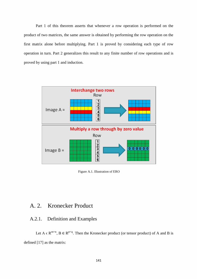
141
Part 1 of this theorem asserts that whenever a row operation is performed on the
product of two matrices, the same answer is obtained by performing the row operation on the
first matrix alone before multiplying. Part 1 is proved by considering each type of row
operation in turn. Part 2 generalizes this result to any finite number of row operations and is
proved by using part 1 and induction.
Figure A.1. Illustration of ERO
A. 2. Kronecker Product
A.2.1. Definition and Examples
Let A ϵ Rm×n, B ∈ Rp×q. Then the Kronecker product (or tensor product) of A and B is
defined [17] as the matrix:

142
A ⊗B= [a11B ⋯ a1nB
⋮ ⋱ ⋮am1B ⋯ amnB
] ∈ Rmp×nq; (A.18)
Obviously, the same definition holds if A and B are complex-valued matrices. For example,
1. Let 𝐴 = [1 2 33 2 1
] and 𝐵 = [2 12 3
]. Then
A⊗B= [B 2B 3B
3B 2B B]= [
2 1 4 2 6 32 3 4 6 6 96 3 4 2 2 16 9 4 6 2 3
]; (A.19)
Note that B ⨂A ≠A⊗B.
2. For any B ∈ Rp×q,
I2⨂B= [B 0
0 B]; (A.20)
Replacing I2 by In yields a block diagonal matrix with n copies of B along the diagonal.
3. Let B be an arbitrary 2 x 2 matrix. Then:
B ⊗ I2= [
b11 0
0 b11
b12 0
0 b12
b21 0
0 b21
b22 0
0 b22
]; (A.21)
The extension to arbitrary B and In is obvious.

143
Figure A.2. Illustration of KP operation
4. Let x ∈ Rm, y ∈ Rm. Then
x ⊗ y = [x1yT, …, xmyT]T= [x1y1, …, x1y
n,x2y
1, …, xmy
n]
T ∈ Rmn; (A.22)
5. Let x ∈ Rm, y ∈ Rm. Then
x ⊗ y = [x1y, …, xmy]T= [
x1y1
⋯ x1yn
⋮ ⋱ ⋮xmy
1⋯ xmy
n
]= xyT ∈ Rm×n; (A.23)
A.2.2. Properties of the Kronecker Product
Let A ∈ Rm×n, B ∈ Rr×s, C ∈ Rn×p, and D∈ Rs×t
Then:

144
(A ⊗B)(C ⊗D)=AC ⊗BD (∈Rmr×pt); (A.24)
Simply verify that:
(A⊗B)(C ⊗D)= [a11B ⋯ a1nB
⋮ ⋱ ⋮am1B ⋯ amnB
] [
c11B ⋯ c1pB
⋮ ⋱ ⋮cn1B ⋯ cnpB
]
= [
∑ a1kck1BDnk=1 ⋯ ∑ a1kckpBDn
k=1
⋮ ⋱ ⋮∑ amkck1BDn
k=1 ⋯ ∑ amkckpBDnk=1
]
= AC ⊗ BD; (A.25)
where:
1. For all A and B,
(A⊗B)T=AT⊗BT (A.26)
2. If A∈Rn×n and B∈Rm×m are symmetric, then A ⊗B is symmetric.
3. If A and B are non-singular,
(A⊗B)-1=A-1
⊗B-1; (A.27)
Using property 1, simply note that:
(A⊗B) (A-1⊗B-1)=I⊗I=I (A.28)
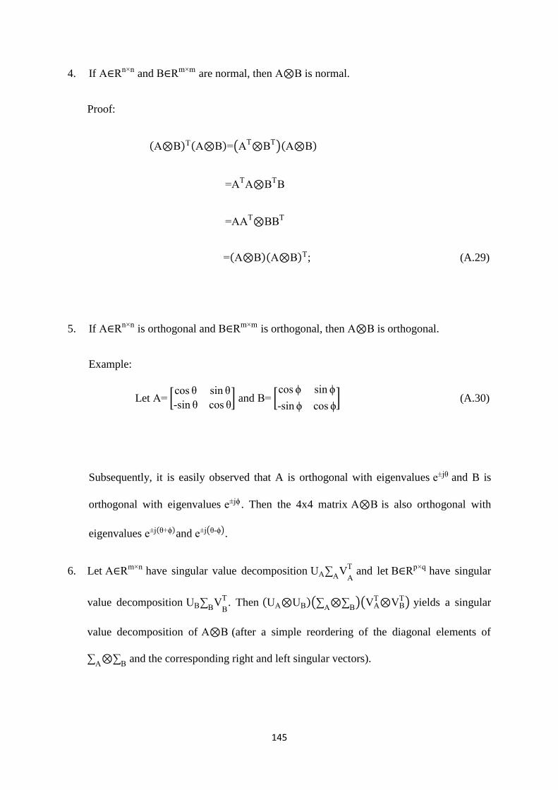
145
4. If A∈Rn×n and B∈Rm×m are normal, then A⊗B is normal.
Proof:
(A⊗B)T(A⊗B)=(AT⊗BT)(A⊗B)
=ATA⊗BTB
=AAT⊗BBT
=(A⊗B)(A⊗B)T; (A.29)
5. If A∈Rn×n is orthogonal and B∈Rm×m is orthogonal, then A⊗B is orthogonal.
Example:
Let A= [cos θ sin θ
-sin θ cos θ] and B= [
cos ϕ sin ϕ
-sin ϕ cos ϕ] (A.30)
Subsequently, it is easily observed that A is orthogonal with eigenvalues e±jθ and B is
orthogonal with eigenvalues e±jϕ . Then the 4x4 matrix A⊗B is also orthogonal with
eigenvalues e±j(θ+ϕ)and e±j(θ-ϕ).
6. Let A∈Rm×n have singular value decomposition UA∑A
VA
T and let B∈Rp×q have singular
value decomposition UB∑B
VB
T. Then (UA⊗UB)(∑A
⊗∑B)(VA
T⊗VBT) yields a singular
value decomposition of A⊗B (after a simple reordering of the diagonal elements of
∑A⊗∑
B and the corresponding right and left singular vectors).

146
7. Let A∈Rm×n have singular values σ1≥…≥σr>0, and
let B∈Rp×q have singular values τ1≥…≥τs>0.
Then A⊗B (or B⊗A has rs singular values σ1τ1≥…≥σrτs>0 and
rank(A⊗B)=(rank A)(rank B)=rank(B⊗A). (A.31)
8. Let A∈Rn×n have eigenvalues λi,i∈n, and
let B∈Rm×m have eigenvalues μj,j∈m.
Then mn eigen values of A⊗B are λ1μ1,…,λ1μ
m, λ2μ
1, …,λ2μ
m,…,λnμ
m (A.32)
Moreover, if x1, …, xp are linearly independent right eigenvectors of A corresponding to
λ1,…,λp(p≤n) and,
z1, …, zq are linearly independent right eigenvectors of B corresponding to
μ1,…,μ
q(q≤m),
then xi⊗zj∈Rmn are linearly independent right eigenvectors of A⊗B corresponding to
λiμj, i∈p, j∈q.
Proof: the basic idea of the proof is as follows:
(A⊗B)(x⊗z)=Ax⊗Bz
=λx⊗μz
=λμ(x⊗z) (A.33)

147
In general, if A and B have Jordan form decomposition given by P-1AP= JA and
Q-1
BQ= JB, respectively, then the subsequent Jordan-like structure is as follows:
(P⊗Q)-1(A⊗B)(P⊗Q)= (P-1⊗Q-1) (A⊗B)(P⊗Q)
= (P-1AP)⊗(Q-1
BQ)
=JA⊗JB (A.34)
A Schur form for A⊗B can be derived similarly. For example, suppose that P and Q are
unitary matrices that reduce A and B respectively, to Schur (triangular) form, i.e.,
PHAP= TA and QH
BQ= TB (and similarly if P and Q are orthogonal similarities reducing
A and B to real Schur form). Then:
(P⊗Q)H(A⊗B)(P⊗Q)=(PH⊗QH)(A⊗B)(P⊗Q)
=(PHAP)⊗(QHBQ)
=TA⊗TB (A.35)
9. Let A∈Rn×nand B∈Rm×m. Then:
b. Tr(A⊗B)=(TrA)(TrB)=Tr(B⊗A) (A36)
c. det(A⊗B)=(detA)m(detB)n=det(B⊗A) (A.37)

148
A. 3. Inverse Matrix Operations
In a matrix domain, whether or not a given 𝑛 × 𝑛 (square) matrix A has a
multiplication inverse matrix (that is, a matrix A-1
such that AA-1
= In) must be considered.
Interestingly, not all square matrices have multiplicative inverses, although most do.
A.3.1. Inverses of Larger Matrix
Let A be an n×n matrix. Then, the method for finding the inverse of a matrix (if it
exists) (inverse method) is as follows [106]:
Step 1: Augment A to an n×2n matrix, whose first n columns constitute A itself and
whose last n columns constitute In.
Step 2: Convert [A|In] into reduced row echelon form.
Step 3: If the first columns of [A|In] cannot be converted into In, then A is singular. Stop.
Step 4: Otherwise, A is non-singular, and the last n columns of the augmented matrix in
reduced row echelon form constitute A-1
. That [A|In] row reduces to [In|A-1].
For example,
A= [
4 2
-2 0
8 1
-4 1
1 4
3 -1
2 0
6 -2
] (A.38)
Beginning with [𝐴|𝐼4] and simplifying the first two columns, obtains:

149
1 0 2 - 1 2⁄
0 1 0 3 2⁄
0 0 0 - 11 2⁄0 0 0 1
||
0 - 1 2⁄ 0 0
1 2⁄ 1 0 0
-2 - 7 2⁄ 1 0
1 2⁄ 5 2⁄ 0 1
(A.39)
Continuing on to the third column, it can be seen that element (3, 3) is zero. Thus, a
type (I) operation cannot be used to make the pivot 1. As the element (4, 3) is also zero, no
type (III) operation (switching the pivot row with a row below it) can make the pivot non-
zero. In summary, there is no way to transform the first four columns into the identity matrix
I4 using the row reduction process, and therefore the original matrix A has no inverse.
A.3.2. System Solving using the Inverse of the Coefficient Matrix
AX = B corresponds to a system where the coefficient matrix A is square. If A is non-
singular, then the system has a unique solution (X=A-1
B). Meanwhile, if A is singular, then
the system has either no solutions or an infinite number of solutions. Hence, AX = B has a
unique solution if and only if A is non-singular.
Proof:
If A is non-singular, then A-1
B is a solution for the system AX = B because
A (A-1
B) = (AA-1)B= InB=B . To show that this solution is unique, suppose Y is any
solution to the system; that is, suppose that AY = B. Then both sides of AY = B on the left by
A-1
can be multiplied to get:
A-1(AY)=A
-1B ⟹ (A
-1A)Y= A
-1B

150
⟹ InY= A-1
B
⟹ Y= A-1
B (A.40)
Therefore, A-1
B is the only solution of AX = B.
Conversely, if A is singular then rank (A) ˂ n, and so not every column of A becomes
a pivot column in the row reduction of the augmented matrix[A|B]. Thus, it can be presumed
that AX = B has at least one solution. Then this system has at least one independent variable
(which can take on any real value), and hence, the system has an infinite number of solutions.