canadian chapter lunch and learn, april 13, 2011 2011 roundtable... · canadian chapter lunch and...
TRANSCRIPT

Canadian Chapter
Lunch and Learn, April 13, 2011
“COILED TUBING INSPECTION: VALUE,
LIMITATIONS, INDUSTRY REQUIREMENTS”
H. B. (Bernie) Luft, PhD, P.Eng.,
Senior Technical Advisor, Trican Well Service

TYPICAL BREAKDOWN FOR SOURCE OF COILED TUBING FAILURES
Mechanical Damage47%Corrosion
24%
Corrosion-Fatigue12%
Other Causes17%
Manufacturing defect, 9%
OperatorError
Pitting

MAGNETIC FLUX LEAKAGE (MFL)Current vector in
magnetizing coil
(alternatively use of permanent magnets)
Magnetic flux or field lines
Magnitude and shape
depends on damage
detail
Off-line rotating magnetic pole CT inspection head for
longitudinal seam weld flaws or defects and WT

ICO-SHEARER COILED TUBING REEL TO REEL INSPECTION SYSTEM
1995 used 1st generation CT inspection system to
measure OD, WT and ovality
Heavy and cumbersome to mount
(not clamshell design) Off-Shore, Aberdeen, Scotland
On-Shore, Red Deer, Alberta (Circa 1995)

ROSEN AUTOMATIC COILED TUBING INTEGRITY MONITORING SYSTEM
(ACIM)
Photos courtesy of Rosen Inspection Technologies (RIT)
MFL Unit GEO UnitODO Unit

Rosen Inspection Technologies
www.RosenInspection.net
Ballooning
Run 5
1.700
1.705
1.710
1.715
1.720
1.725
1.730
1.735
1.740
1.745
1.750
1.755
1.760
1.765
1.770
1.775
1.780
10958 10960 10962 10964 10966 10968 10970 10972 10974 10976
Depth / Length [m]
Ou
ter
Dia
me
ter
[inch
]
0.0
0.5
1.0
1.5
2.0
2.5
3.0
3.5
4.0
4.5
5.0
5.5
6.0
6.5
7.0
7.5
8.0
Ou
t o
f R
ou
nd
ne
ss [
%]
Minimum
Average
Maximum
Ovality
OUTER DIAMETER (OD) and OVALITY (Ov) SCANS(Courtesy of Rosen Inspection Technologies (RIT))

WALL THICKNESS (WT) and C-SCANS for CT PITTING(Courtesy of Rosen Inspection Technologies (RIT))
Circumference
De
pth
C-Scan plot of corrosion pits in CT.
Red colours indicate greater pit depths
WT Scan @ cycle #61. LCF occurred at
#69. Red areas show local wall thinning
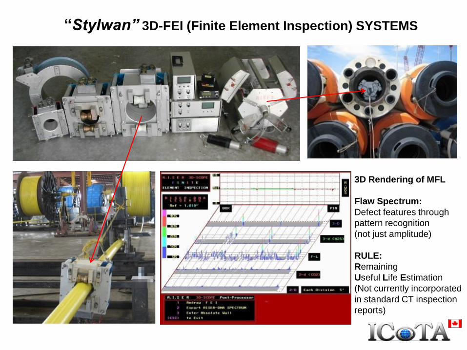
“Stylwan” 3D-FEI (Finite Element Inspection) SYSTEMS
3D Rendering of MFL
Flaw Spectrum:
Defect features through
pattern recognition
(not just amplitude)
RULE:
Remaining
Useful Life Estimation
(Not currently incorporated
in standard CT inspection
reports)

Stylwan’s 3D-FEI (FINITE ELEMENT INSPECTION)(Courtesy CSM Tubular Technologies, Red Deer)
System claimed to detect rapid fatigue consumption and
identify at least 2 predominant failure locations as early as
50% of fatigue life
A CT section was cycled
on a CTU at 10,000 psi.
Predicted fatigue: 45 cycles
3D-FEI detected and marked
exact failure location according
to their technical literature

“Stylwan” TRACES
for
WALL THICKNESS
and WT DEVIATIONS
of
TAPERED STRINGS(Courtesy CSM Tubular
Technologies, Red Deer)
Re
so
luti
on
Should expand scale!
API 5ST “NEW“ CT:
< 0.110”: -0.005” to+0.010”
< 0.175”: -0.008” to+0.012”
< 0.250”: -0.012” to +0.012”
>0.250”: -0.015” to +0.015”
IRP 21 “USED“ CT:
max 10% loss of spec WT
Spikes are step changes
in WT referenced after
WT transition
0.204”0.190”
0.175”0.156”
%W
T D
evia
tio
n

“Stylwan” SURFACE DAMAGE INDICATION TRACES (2-T, 3-T) and
RELATIVE SEVERITY of FATIGUE DEGRADATION (Es) TRACE(Courtesy CSM Tubular Technologies, Red Deer, Ref. CSM Report #212)
3-T Trace: Green scan from multiple sensors arranged for 3-dimensional mensuration of corrosion pits, conical pits and gouges
2-T Trace: Blue scan from sensors used for 2-dimensional flaws or defects such as visible cracks or edge cracks (“crack seeds”)
Es Trace: Summary scan of “Environmental Sensitivity” provides map of relative severities to string degradation (eg.
(susceptibility to fatigue failure) at various locations along string length. Also referred to as “Fatigue Line”
End damage section,
CT cut off
Suspect plough
mark, 17.6% WTNote Es line not at 0%,
Possible explanation:
Full length continuous
longitudinal wear grooves
and/or general corrosion
100% means CT
in perfect condition

itRobotics COILED TUBING ASSESSMENT SYSTEM (CTAS)(Photos and graphics Courtesy Dr. Rod Stanley, itRobotics Inc.)
Clamshell design for mounting and inspecting shorter intermediate sections

LATEST CT INSPECTION HEAD DESIGN(exchangeable sensor rings for varying CT diameter)
Signal cable
junction box
Neodymium “(Nd)-Fe-B” permanent magnets for
longitudinal field induction
Clamshell design
for mounting &
intermediate section
inspection
Eddy current non-
contact sensors for
OD and Ov measure
Four (4) sliding CT contact shoes or wedges containing
multiple Hall effect sensors encircling the CT for MFL signals
to measure wall thickness and detect imperfections and defects
Wt: ~150 lbs for 2-7/8” CT
~200 lbs for 3-1/4”, 3-1/2” CT

COMPUTER SCREEN FROM 1-3/4 X 0.134 CT
360 degree
Map (C-Scan)
Electronic note pad
Lamps light when MFL
in octant. Helps to
to locate defect(s)
during prove up.
Scales show tube dimensions
Max, min, avg OD
Wall loss
area
Max, min, avg WT
Butt
weld1/32” TDH TID
TOD
Vibration scan to detect false MFL signals
Speedometer
MFL signal
Threshold
(manual set)
Audible alarm
(manual set)

CALIBRATION TO API 5ST
STANDARDS AND
EXXONMOBIL SPECIFICATIONS
Butt weld
1/32” Through drilled
hole (TDH) in seam weld
OD and ID transverse (TOD,TID)
and longitudinal (LOD, LID)
EDM reference notches
10% wall thickness (WT) longitudinal
and transverse notches
1/32” through drilled hole (new CT)
1/16” through drilled hole (used CT)
Wall thickness reduction

DIGITIZING, 3D RENDERING AND ARCHIVING OF MFL SCANS FOR
SUBSEQUENT ENGINEERING CRITICAL ANALYSES (ECA)
Transverse notchLongitudinal notch
MFL Hall sensor signals from
all four (4) shoes or wedges.
(Digitized every 0.5 mm)
Measures length of longitudinal flaw or defect
(MFL peaks emanate from ends of longitudinal OD & ID notches)
MFL map can be rotated to
Measure length of longitudinal
notches

VALUE, BENEFITS AND IMPORTANCE OF CT INSPECTIONS
All mechanical and corrosion damage reduce fatigue life to varying
degree. Need to predict remaining safe working life.
Economics: want to maximize service life of expensive consumables
Safety: want to avoid catastrophic failures such as large fatigue cracks
in high pressure operations and/or higher strength CT.
Verify integrity of newly manufactured “high profile” or critical strings

QUANTIFYING LOSS OF CT FATIGUE FROM MECHANICAL DAMAGE
Artificial Damage Detail
R=D/2
d
w
end view side section view
c
x
Fig. 6 – Geometry of defects milled with ball-nose cutter. (Inset photo shows the four
actual 0.625” deep cuts on a 2.375” diameter sample.)
x
top view
wtube axis
a b fd ec g h i
Fig. 1 – Defect geometries and EDM samples.
3
1
c
p
A
A
x
w
t
dQ
c
b
b
Q
aa
N
N
1
exp
a = 9.222 b = 1.0339 c = 2.20735

DETERMINE CT FATIGUE DE-RATING FACTOR (N/Nb)
or DEFECT INTENSITY FACTOR (DIF = Nb/N)
0
0.2
0.4
0.6
0.8
1
1.2
1.4
0 0.2 0.4 0.6 0.8 1 2Q
dd-TUdd-BAmc-ball-TU-48mc-cyl-TU-48mc-co-TU-48wx-TUstat-BAwx-BAimp-TULMmc-ball-TU-72mc-cyl-TU-72mc-co-TU-72edm-ball-TU-72edm-cyl-TU-72edm-co-TU-72sdjip-fit
0.1 0.3 0.5 0.7 0.9 1.5
N = CT fatigue cycles with surface damage Nb = Baseline CT fatigue cycles without damage
Q = Damage parameter N/Nb = Fatigue de-rating factor
N/N
b
c
b
b
Q
aa
N
N
1
exp

“FLEXOR TU” SOFTWARE INTERFACE FOR NEWAND DAMAGED CT FATIGUE PREDICTIONS

ECA Example Using Flexor TU-Corrosion Pits – Test Case #1
CT AND DAMAGE DETAILS:
•1-1/4” X 0.095” (31.2 mm X 2.41 mm) CT80
•18% working life consumed
•Transverse OD surface corroded edge cracks
PHYSICAL MEASUREMENTS:
•0.5 mm (0.0197”) long (w), 0.0625 mm (0.0025”) wide (x),
0.125 mm (0.0049”) deep (d)
•%WT = d/t X 100 = 5.2%
•w/x = 0.5/0.0625 = 8
PREDICTION OF FATIGUE DEGRADATION:
•Defect Intensity Factor @ 1000 psi = 1.42. Divide
remaining fatigue life by1.42 (i.e. remaining fatigue life is
reduced to 1/1.42 or 70.4% of non-damaged fatigue)
•Defect Intensity Factor @ 6000 psi = 1.21. Divide
remaining fatigue life by1.21(i.e. remaining fatigue life is
reduced to 1/1.21 or 82.9% of non-damaged fatigue)
BFM FATIGUE TEST RESULTS:
Fatigue loss at 1,000 psi: 31.7%, at 6,000 psi 15.6%
RECOMMENDATION:
Reduce remaining fatigue by 25%
d = 0.125 mm
x = 0.0625 mm
w = 0.5 mm

ECA Example Using Flexor TU-Corrosion Pits - Test Case #2
1-1/2” diam x 0.175” thick, CT100
CT exposed to sea environment. Pitting corrosion on OD and ID surfaces
BFM Test Parameters: 72” Bend Form Radius; 500 psi internal pressure

EXAMPLE OF “Flexor TU” APPLICATION-CORROSION PITS
ON BOTH INTERNAL AND EXTERNAL SURFACES
External Pit Internal Pit
d (mm)
D
(mm)
d (mm)
D
(mm)
0.42 0.247 0.07 0.2
D: pit diameter; d: pit depth
Crack from OD
Small crack
from ID Connection
OD
ID 1 mm
40 μm
40 μm
Pinhole Longitudinal Section External Pit Detail Internal Pit Detail
Sample S12
d

EXAMPLE OF “Flexor TU” APPLICATION-CORROSION PITS
ON BOTH INTERNAL AND EXTERNAL SURFACES
External Pit Internal Pit
d (mm)
D
(mm)
d (mm)
D
(mm)
0.31 0.565 0.09 0.502
D: Pit Diameter; d: pit depth
Pinhole Longitudinal SectionExternal Pit Detail Internal Pit Detail
Crack from
OD
Connection
Crack from ID
1 mm
OD
ID
40 μm
40 μm
Sample S6
d
d
WT

COMPARISON BETWEEN BFM TESTS AND “FLEXOR TU” PREDICTIONS
SampleN predicted1
(cycles)
Nf BFM test2
(cycles)
Difference3
(%)
S12 877 804+9.1
(i.e. optimistic)
S6 885 997-11.2
(i.e. pessimistic)
(1) Predictions assuming simultaneous crack propagation from OD & ID pits.
Cut defects, cylindrical shape, constant pit diameter to full depth of pit
(2) Nf = Failure cycles measured with BFM
(3) Difference: [(N predicted – Nf) / Nf] x 100
Often conservative but sometimes optimistic estimates of remaining fatigue life

EXAMPLE OF MECHANICAL DAMAGE – “PERF BURNS”
(2” X 0.175” or 50.8mm X 4.45 mm CT80)
Summary of CT Damage ECA: ( Pressure = 3,000 psi (21 MPa), BFM Bend Form: 72”R)
Hemispherical, x = w = 0.32” (scaled from photo), dmax = 0.012” , Nf/Nb = 426/504 = 0.845 (DIF = 1.182)
Hemispherical, larger diameter, x = w = 0.5”, dmax = 0.012” , Nf/Nb = 411/504 = 0.815 (DIF = 1.226)
Hemispherical, greater depth, x = w = 0.32”, dmax = 0.015” , Nf/Nb = 403/504 = 0.801 (DIF = 1.249)
Ellipsoidal, Longitudinal (w/x < 1), x = 0.5”, w = 0.32”, dmax = 0.012”, Nf/Nb = 450/504 = 0.892 (DIF = 1.121)
Ellipsoidal, Transverse (w/x > 1), x = 0.32”, w = 0.5”, dmax = 0.012”, Nf/Nb = 375/504 = 0.744 (DIF = 1.344)

SOME LIMITATIONS OF REEL TO REEL CT INSPECTIONS
1 mm
1 mm
OD
ID
Severe plough marks
Outer diameter, OD
Severe ploughing or scraping causes large plastic distortion of grains and transverse edge
cracks (see arrows).
Tests have shown that fatigue propagation to pinhole failure can occur in only 1 or 2 trips into
and out of the well.
More laboratory testing required on realistic defects such as deep plough marks. Present example would call for cut out and butt weld repair
Downhole direction
1 mm
1 mm
Inside diameter, ID
Crack ID

SOME LIMITATIONS OF REEL TO REEL CT INSPECTIONS
25 µm
(0.001” or
0.025mm)
10 µm
Outer Diameter, OD“Saw Tooth” detail
~ 0.25 mm
Sharp notch effects. Depth
of only 0.25 mm or can
reduce fatigue by 25%.
Resolution of inspection
system may be too low

PH = Pinhole – Longitudinal section
Cracking associated with banding
PH
HIC crack
Banding
1 mm
20 µm50 µm
SOME LIMITATIONS OF REEL TO REEL CT INSPECTIONS
Mid-wall planar Hydrogen Induced Cracks (HIC) from Sour Well Exposure

EXAMPLES OF DAMAGE DETAILS REQUIRING MORE
ENGINEERING JUDGEMENT AND/OR TESTS ON REALISTIC DEFECTS
10 µm
50 µm
Longitudinal direction
Mechanical Damage (irregular shape or with
micro-cracks and plastically deformed grains)
A A

REMAINING INDUSTRY NEEDS AND ON-GOING R & D
Standardization on different defect terminology –(Some definitions already standardized in API 5ST.
Incorporate in API 5C8 currently under development?)
Atlas of relative defect severity with respect to fatigue(Incorporate in API 5C8 currently under development?)
Efficient prove-up tool for measuring critical defect dimensions(Currently under development at TU CTMRC i.e. Laser Scanning Measuring Tool)
Increased BFM tests on realistic defects and comparison with FLEXOR TU(Currently under development at Tulsa University CTMRC)
Increased resolution for on-line detection of cold weld/penetrator defects
(Possibly non-contact divergent eddy current technology)
Additional training of CT string inspectors
Check out Aradia Consulting web site www.ctfatigue.com


TYPICAL MFL SIGNALS
Longitudinal notchTransverse notch
Detectable notches with background “white” noise

SURFACE REPAIR PROCEDURE FOR COILED TUBING(Ref. Tipton, S. M. et al, “Repairing Surface Flaws in Coiled Tubing”, SPE/ICoTA, 10th European Coiled Tubing and
Well Intervention Round Table, Nov. 16-17, 2004)
Direction of filing and surface finish is very
important.
Visible grind marks can lead to early fatigue
crack initiation.

SIMULATED SURFACE REPAIR OF PLOUGH MARK IN 60.3 X 3.9
mm
Optimum profile: gradually increasing wall thickness away from defect
Poor profile: too much wall thickness removed along tubing length
Poor profile: abrupt changes/waviness in wall thickness
L = 2D
R
Plough defect
Transverse cutter marks
Life: 14 cycles
Longitudinally filed
smooth surface, Life: 28 cycles
Tested at high
pressure,
4840 psi (33.4 MPa)
D = CT diameter
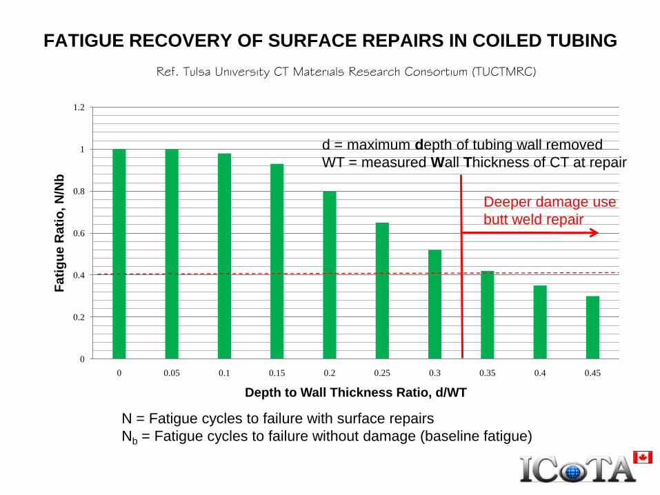
FATIGUE RECOVERY OF SURFACE REPAIRS IN COILED TUBING
0
0.2
0.4
0.6
0.8
1
1.2
0 0.05 0.1 0.15 0.2 0.25 0.3 0.35 0.4 0.45
Fa
tig
ue
Ra
tio
, N
/Nb
Depth to Wall Thickness Ratio, d/WT
Ref. Tulsa University CT Materials Research Consortium (TUCTMRC)
N = Fatigue cycles to failure with surface repairs
Nb = Fatigue cycles to failure without damage (baseline fatigue)
d = maximum depth of tubing wall removed
WT = measured Wall Thickness of CT at repair
Deeper damage use
butt weld repair

EXAMPLES OF CT MECHANICAL DAMAGE SUITABLE FOR SURFACE REPAIR
“Plough” marks “Sawtooth” marks
Isolated and
shallow damage