calibration procedure ni virtualbench · calibration procedure ni virtualbench vb-8012, vb-8034,...
TRANSCRIPT

CALIBRATION PROCEDURE
NI VirtualBenchVB-8012, VB-8034, and VB-8054 All-In-One Instrument
This document contains the verification and adjustment procedures for the National Instruments VirtualBench VB-8012, VB-8034, and VB-8054. For more information about calibration solutions, visit ni.com/calibration.
ContentsSoftware and Firmware ...........................................................................................................1Documentation.........................................................................................................................2Test Equipment........................................................................................................................2Test Conditions........................................................................................................................4Digital Multimeter (DMM) Calibration Procedure .................................................................4
DMM Test Equipment.....................................................................................................5DMM Test Conditions.....................................................................................................5DMM Initial Setup...........................................................................................................6DMM Verification...........................................................................................................6
Verifying DC Voltage .............................................................................................6Verifying AC Voltage .............................................................................................9Verifying Resistance................................................................................................11Verifying DC Current ..............................................................................................14Verifying AC Current ..............................................................................................17
DMM Adjustment............................................................................................................19Setting Up the Test Equipment................................................................................20Adjusting DC Voltage .............................................................................................20Adjusting AC Voltage .............................................................................................21Adjusting Resistance ...............................................................................................22Adjusting AC and DC Current ................................................................................24
DMM EEPROM Update .................................................................................................25DMM Re-Verification .....................................................................................................26
Oscilloscope Calibration Procedure ........................................................................................26Oscilloscope Test Equipment ..........................................................................................26Oscilloscope Test Conditions ..........................................................................................27Oscilloscope Initial Setup................................................................................................27Oscilloscope Verification ................................................................................................28
Verifying the Oscilloscope Offset ...........................................................................28Verifying the Oscilloscope Gain .............................................................................31Verifying the Oscilloscope Offset DAC Gain.........................................................36
Oscilloscope Adjustment.................................................................................................42Oscilloscope EEPROM Update.......................................................................................46Oscilloscope Re-Verification ..........................................................................................46
™

2 | ni.com | NI VirtualBench Calibration Procedure
Function Generator (FGEN) Calibration Procedure ............................................................... 46FGEN Test Equipment.................................................................................................... 47FGEN Test Conditions.................................................................................................... 47FGEN Initial Setup ......................................................................................................... 48FGEN Verification.......................................................................................................... 48
Verifying the FGEN Offset..................................................................................... 48Verifying the FGEN Gain....................................................................................... 49
FGEN Adjustment .......................................................................................................... 50FGEN EEPROM Update ................................................................................................ 52FGEN Re-Verification.................................................................................................... 52
DC Power Supply Calibration Procedure ............................................................................... 52DC Power Supply Test Equipment ................................................................................. 53DC Power Supply Test Conditions ................................................................................. 53DC Power Supply Initial Setup....................................................................................... 54DC Power Supply Verification ....................................................................................... 54
Verifying Voltage Programming and Measurement Accuracy .............................. 55Verifying Current Programming and Measurement Accuracy............................... 60
DC Power Supply Adjustment........................................................................................ 64Adjusting Voltage Programming and Measurement Accuracy .............................. 64Adjusting Current Programming and Measurement Accuracy............................... 68
DC Power Supply EEPROM Update.............................................................................. 72DC Power Supply Re-Verification ................................................................................. 72
Where to Go for Support ........................................................................................................ 72
Software and FirmwareCalibrating the NI VirtualBench requires the installation of NI VirtualBench application development support and NI LabVIEW 2013 or later on the Windows calibration system. You can download the software and driver from ni.com/downloads.
Table 1 lists the earliest required firmware support for VirtualBench calibration. You can update the firmware through the VirtualBench application.
Table 1. VirtualBench Calibration Firmware Support
VirtualBench Earliest Firmware Support
VB-8012 Version 1.1.2
VB-8034 Version 15.1
VB-8054 Version 16.1

NI VirtualBench Calibration Procedure | © National Instruments | 3
DocumentationConsult the following documents for information about the NI VirtualBench and your application software. All documents are available on ni.com and help files install with the software.
Test EquipmentTable 2 lists all recommended equipment for the performance verification and adjustment procedures for all VirtualBench instruments. If the recommended equipment is not available, select a substitute using the requirements listed in the table.
NI VirtualBench VB-8012 Quick Start or NI VirtualBench VB-8034/8054 Quick Start
Contains: NI VirtualBench hardware installation, software launching
NI VirtualBench VB-8012 Specifications, NI VirtualBench VB-8034 Specifications, or NI VirtualBench VB-8054 Specifications
Contains: specifications and calibration interval for your VirtualBench
NI VirtualBench VI Reference Help
Contains: LabVIEW programming concepts and reference information about NI VirtualBench VIs and functions
Table 2. VirtualBench Calibration Recommended Equipment
EquipmentRecommended
ModelInstrument Calibration
Minimum Requirements
Multifunction calibrator
Fluke 5700A/5720A/5730A
Digital Multimeter (DMM) Calibration Procedure
Must be calibrated within the last year.
Low thermal electromotive force (EMF) copper cable
Fluke 5440A-7002 Digital Multimeter (DMM) Calibration Procedure
Low thermal electromotive force (EMF) copper cable with 4 mm banana connectors.
Amplifier Fluke 5725A Digital Multimeter (DMM) Calibration Procedure
Must be calibrated within the last year.
Shielded interface cable for the amplifier
Fluke 842901 Digital Multimeter (DMM) Calibration Procedure
—

4 | ni.com | NI VirtualBench Calibration Procedure
50 Ω terminator Amphenol 000-46650-51RFX
Oscilloscope Calibration Procedure
VB-8012 only.
Oscilloscope calibrator
Fluke 9500B calibrator
Oscilloscope Calibration Procedure
Vertical gain: DC ±(0.025% + 25 μV) into 1 MΩ
Oscilloscope calibrator active head
Fluke 9530 Oscilloscope Calibration Procedure
DC operation
Function generator NI 5421 Oscilloscope Calibration Procedure (adjustment section)
Must be able to generate a 1 kHz square wave between 36 mVpp and 18 Vpp with less than 200 ns rise time and less than 5% overshoot.
SMB to BNC cable NI part number 778827-01
Oscilloscope Calibration Procedure
Cable needed to connect from the function generator to the VirtualBench BNC connectors.
Digital multimeter (DMM)
NI PXI-4071 Function Generator (FGEN) Calibration Procedure, DC Power Supply Calibration Procedure
DC V accuracy: 21 ppm at 25 VDC input impedance: ≥1 GΩDC A accuracy: 310 ppm at 1 A, 460 ppm at 2 A
Banana plug-to-BNC cable
Pomona 4530-C Function Generator (FGEN) Calibration Procedure
—
Cabling wire — DC Power Supply Calibration Procedure
18 AWG to 22 AWG. Twisted pair, shielded cabling wire is recommended
Table 2. VirtualBench Calibration Recommended Equipment (Continued)
EquipmentRecommended
ModelInstrument Calibration
Minimum Requirements

NI VirtualBench Calibration Procedure | © National Instruments | 5
Test ConditionsFollow these guidelines to optimize the equipment and the environment during calibration:• Keep connections to the device as short as possible. Long cables and wires act as antennae,
picking up noise that can affect measurements.• Use a USB connection between the PC and VirtualBench.• Verify that all connections to the device, including front panel connections, are secure.• Keep relative humidity between 10% and 80% noncondensing.• Allow a warm up time of at least 30 minutes to ensure that the VirtualBench is at a stable
operating temperature. • Plug the VirtualBench, PC, and the test equipment into the same power strip to avoid
ground loops.• Verification limits are defined assuming the same test equipment is used during verification
and adjustment.• (Oscilloscope, FGEN, and DC Power Supply Procedures) Maintain an ambient
temperature of 23 ±5 °C. The device temperature will be greater than the ambient temperature.
• (DMM Procedure) Maintain an ambient temperature of 23 ±1 °C. The device temperature will be greater than the ambient temperature.
• (DMM Procedure) Clean any oxidation from the banana plugs on the Fluke 5440 cables before plugging them into the binding posts of the calibrator or the banana plug connectors on the VirtualBench. Oxidation tarnishes the copper banana plugs so that they appear dull rather than shiny and leads to greater thermal EMF.
• (DMM Procedure) Keep the blue banana plugs on the Fluke 5440 cables connected to the V GUARD binding post of the calibrator at all times.
• (DMM Procedure) Prevent the cables from moving or vibrating by taping or strapping them to a nonvibrating surface. Movement or vibration causes triboelectric effects that can result in measurement errors.
• (DC Power Supply Procedure) Use shielded copper wire for all cable connections. Use twisted-pair, shielded wire to reduce measurement error in noisy environments.
Digital Multimeter (DMM) Calibration ProcedureThis section contains the verification and adjustment procedures for the DMM on the VirtualBench. The calibration process includes the following steps:1. DMM Initial Setup—Set up the test equipment.2. DMM Verification—Verify the existing operation of the instrument. This step confirms
whether the instrument is operating within its specified range prior to adjustment.3. DMM Adjustment—Perform an external adjustment of the instrument that adjusts the
calibration constants with respect to standards of known values.4. DMM Re-Verification—Repeat the verification procedure to ensure that the instrument is
operating within its specifications after adjustment.

6 | ni.com | NI VirtualBench Calibration Procedure
These steps are described in more detail in the following sections.
Note If you are calibrating both the DMM and the DC power supply, the DMM must be calibrated first.
DMM Test EquipmentTable 3 lists the equipment recommended for the DMM performance verification and adjustment procedures. If the recommended equipment is not available, select a substitute using the requirements listed in the table.
DMM Test ConditionsFollow these guidelines to optimize the equipment and the environment during calibration:• Keep connections to the device as short as possible. Long cables and wires act as antennae,
picking up noise that can affect measurements.• Use a USB connection between the PC and VirtualBench.• Verify that all connections to the device, including front panel connections, are secure.• Keep relative humidity between 10% and 80% noncondensing.• Allow a warm up time of at least 30 minutes to ensure that the VirtualBench is at a stable
operating temperature. • Plug the VirtualBench, PC, and the test equipment into the same power strip to avoid
ground loops.• Verification limits are defined assuming the same test equipment is used during verification
and adjustment.• Maintain an ambient temperature of 23 ±1 °C. The device temperature will be greater than
the ambient temperature.
Table 3. Recommended Equipment
EquipmentRecommended
Model Minimum Requirements
Multifunction calibrator
Fluke 5700A/5720A/5730A
Must be calibrated within the last year.
Low thermal electromotive force (EMF) copper cable
Fluke 5440A-7002 Low thermal electromotive force (EMF) copper cable with 4 mm banana connectors.
Amplifier Fluke 5725A Must be calibrated within the last year.
Shielded interface cable for the amplifier
Fluke 842901 —

NI VirtualBench Calibration Procedure | © National Instruments | 7
• Clean any oxidation from the banana plugs on the Fluke 5440 cables before plugging them into the binding posts of the calibrator or the banana plug connectors on the VirtualBench. Oxidation tarnishes the copper banana plugs so that they appear dull rather than shiny and leads to greater thermal EMF.
• Keep the blue banana plugs on the Fluke 5440 cables connected to the V GUARD binding post of the calibrator at all times.
• Prevent the cables from moving or vibrating by taping or strapping them to a nonvibrating surface. Movement or vibration causes triboelectric effects that can result in measurement errors.
DMM Initial Setup
Note This section is necessary for pre-adjustment verifications only. If you are performing a post-adjustment verification, skip the setup and go directly to the DMM Verification section.
To set up the test equipment, complete the following steps:1. If VirtualBench is running, shut down all instruments on the VirtualBench, and close the
VirtualBench software. Remove all signal connections.2. Verify that the calibrator has been calibrated within the time limits specified in the DMM
Test Equipment section, and that DC zeros calibration has been performed within the last 30 days. Consult the Fluke user documentation for instructions on calibrating these devices.
Note Ensure that the VirtualBench is warmed up for at least 30 minutes.
3. Call DMM Initialize to create a session. For more information on using DMM Initialize, refer to the NI VirtualBench VI Reference Help.
Note You use this session in all subsequent function calls throughout the verification procedures.
DMM VerificationYou can use the verification procedures described in this section for both pre-adjustment and post-adjustment verification. The steps of each verification procedure must be performed in the order listed; however, you can omit entire sections (for example, the entire Verifying AC Current section), if necessary.
Verifying DC Voltage To verify the DC voltage function of the VirtualBench DMM, complete the following steps:1. Reset the calibrator.2. Connect the red connectors on one end of the low thermal electromotive force (EMF)
copper cable to the banana plug connectors of the VirtualBench, and connect the connectors on the other end of the cable to the appropriate calibrator binding posts. Figure 1 shows the correct connections.

8 | ni.com | NI VirtualBench Calibration Procedure
Figure 1. Cable Connections for DC Voltage
3. Wait 2 minutes for the thermal EMF to stabilize.4. Null the points by completing the following steps:
a. For the 100 mV range, set the calibrator to 0 V.
Note When outputting less than 220 mV, range lock the calibrator to 2.2 V so it prevents creating a voltage divider with the internal resistance of the VirtualBench.
b. Call DMM Configure Measurement with the following parameters:• Function = DC Volts• Auto Range = FALSE• Manual Range = 0.1
c. Set the input resistance of the VirtualBench to 10 GΩ by calling DMM Configure DC Voltage with the following parameter: • Input Resistance = 10 GOhm
d. Call DMM Read. Record this measurement.5. Generate 0.101 V verification point on the calibrator.6. Call DMM Configure Measurement with the following parameters:
• Function = DC Volts• Auto Range = FALSE• Manual Range = 0.1
7. Set the input resistance of the VirtualBench to 10 GΩ by calling DMM Configure DC Voltage with the following parameter: • Input Resistance = 10 GOhm
1 VirtualBench DMM 2 Multifunction Calibrator 3 Low EMF Copper Cable
HI
LO
HI
LO
HVI
SENSEVΩ
OUTPUTVΩA
AUXCURRENT
GUARD GROUND
3
1 2

NI VirtualBench Calibration Procedure | © National Instruments | 9
8. Call DMM Read. Subtract the saved value from step 4 and compare to the limits listed in Table 4.
Note Use the values in the 24 Hour Limits column for a post-adjustment verification only. Otherwise, use the values in the 1 Year Limits column.
9. Repeat steps 5 through 8 for each verification point listed for the 100 mV range in Table 4.10. Generate 1.01 V verification point on the calibrator.11. Call DMM Configure Measurement with the following parameters:
• Function = DC Volts• Auto Range = FALSE• Manual Range = 1
12. Set the input resistance of the VirtualBench by calling DMM Configure DC Voltage with the following parameter: • Input Resistance = 10 GOhm
13. Call DMM Read. Compare to the limits listed in Table 4.
Table 4. VirtualBench DC Voltage Verification Limits
Range (V)
Verification Point (V)
Input Resistance
1 Year Limits (V) 24 Hour Limits (V)
Lower Upper Lower Upper
0.1 0.101 10 GΩ 0.100980 0.101020 0.100996 0.101004
0 -0.000005 0.000005 -0.000003 0.000003
-0.101 -0.101020 -0.100980 -0.101004 -0.100996
1 1.01 10 GΩ 1.009800 1.010200 1.009960 1.010040
0 -0.00005 0.00005 -0.00002 0.00002
-1.01 -1.010200 -1.009800 -1.010040 -1.009960
10 10.1 10 GΩ 10.0980 10.1020 10.0997 10.1003
0 -0.0005 0.0005 -0.0002 0.0002
-10.1 -10.1020 -10.0980 -10.1003 -10.0997
100 101 10 MΩ 100.960 101.040 100.993 101.007
0 -0.005 0.005 -0.002 0.002
-101 -101.040 -100.960 -101.007 -100.993
300 150 10 MΩ 149.933 150.068 149.979 150.021
0 -0.015 0.015 -0.014 0.014
-150 -150.068 -149.933 -150.021 -149.979

10 | ni.com | NI VirtualBench Calibration Procedure
14. Repeat steps 10 through 13 for each verification point in the remaining ranges listed in Table 4.
15. Reset the calibrator for safety reasons.16. Disconnect all cables from the calibrator and VirtualBench.
You have completed verifying the DC voltage function of the VirtualBench.
Verifying AC Voltage To verify the AC voltage function of the VirtualBench DMM, complete the following steps:1. Reset the calibrator.2. Connect the red connectors on one end of the low EMF copper cable to the banana plug
connectors of the VirtualBench, and connect the connectors on the other end of the cable to the appropriate calibrator binding posts. Figure 2 shows the correct connections.
Figure 2. Cable Connections for AC Voltage
3. Wait 2 minutes for the thermal EMF to stabilize.
Note Thermal EMF stabilization time is not needed if the cables have not been connected/reconnected.
4. Generate 0.006 Vrms verification point on the calibrator.5. Call DMM Configure Measurement with the following parameters:
• Function = AC Volts• Auto Range = FALSE• Manual Range = 0.1
1 VirtualBench DMM 2 Multifunction Calibrator 3 Low EMF Copper Cable
HI
LO
HI
LO
HVI
SENSEVΩ
OUTPUTVΩA
AUXCURRENT
GUARD GROUND
3
1 2

NI VirtualBench Calibration Procedure | © National Instruments | 11
6. Call DMM Read. Compare to the limits listed in Table 5.
Note Use the values in the 24 Hour Limits column for a post-adjustment verification only. Otherwise, use the values in the 1 Year Limits column.
7. Repeat steps 4 through 6 for each verification point listed in Table 5 for all ranges.8. Reset the calibrator for safety reasons.9. Disconnect all cables from the calibrator and VirtualBench.
You have completed verifying the AC voltage function of the VirtualBench.
Table 5. VirtualBench AC Voltage Verification Limits
Range (Vrms)
Verification Point
Frequency (kHz)
Verification Point (Vrms)
1 Year Limits (Vrms) 24 Hour Limits (Vrms)
Lower Upper Lower Upper
0.1 1 0.006 0.005943 0.006057 0.005988 0.006012
0.05 0.049890 0.050110 0.049984 0.050016
0.101 0.100829 0.101171 0.100979 0.101021
1 1 0.06 0.05943 0.06057 0.05988 0.06012
0.5 0.49890 0.50110 0.49984 0.50016
1.01 1.00829 1.01171 1.00979 1.01021
10 1 0.6 0.5943 0.6057 0.5988 0.6012
5 4.9890 5.0110 4.9984 5.0016
10.1 10.0829 10.1171 10.0979 10.1021
100 1 6 5.943 6.057 5.988 6.012
50 49.890 50.110 49.984 50.016
101 100.829 101.171 100.979 101.021
265 1 15.9 15.748 16.052 15.868 15.932
66.25 66.038 66.462 66.213 66.287
135.15 134.855 135.445 135.107 135.193

12 | ni.com | NI VirtualBench Calibration Procedure
Verifying ResistanceTo verify the resistance function of the VirtualBench, complete the following steps:1. To verify resistance ≤19 kΩ, connect the red connectors on one end of the low EMF copper
cable to the banana plug connectors of the VirtualBench, and connect the connectors on the other end of the cable to the appropriate calibrator binding posts. Figure 3 shows the correct connections.
Figure 3. Cable Connections for Resistance ≤19 kΩ
2. Wait 2 minutes for the thermal EMF to stabilize.
Note Thermal EMF stabilization time is not needed if the cables have not been connected/reconnected.
3. Call DMM Configure Measurement with the following parameters:• Function = Resistance• Auto Range = FALSE• Manual Range = 100
4. Set the calibrator to output 0 Ω with 2-wire compensation turned on.5. Call DMM Read to allow the calibrator to properly settle.6. Wait 5 seconds for settling.7. Call DMM Read 20 times. Calculate and record the average value.8. Output 1 Ω verification point on the calibrator.9. Call DMM Configure Measurement with the following parameters:
• Function = Resistance• Auto Range = FALSE• Manual Range = 100
1 VirtualBench DMM 2 Multifunction Calibrator 3 Low EMF Copper Cable
HI
LO
HI
LO
HVI
SENSEVΩ
OUTPUTVΩA
AUXCURRENT
GUARD GROUND
3
1 2

NI VirtualBench Calibration Procedure | © National Instruments | 13
10. Call DMM Read 20 times. Calculate and record the average value. Subtract the average value measured in step 7. Verify that the result falls between the limits listed in Table 6.
Note Use the values in the 24 Hour Limits column for a post-adjustment verification only. Otherwise, use the values in the 1 Year Limits column.
Note Limits are provided for resistance instead of absolute limits because the limits depend on the actual resistance value output by your calibrator.
11. Repeat steps 8 through 10 for each verification point of the 100 Ω range listed in Table 6.12. Repeat steps 3 through 11 for every range in Table 6.13. To verify resistance >19 kΩ, call DMM Configure Measurement with the following
parameters:• Function = Resistance• Auto Range = FALSE• Manual Range = 100 kΩ
14. Set the calibrator to output 0 Ω with 2-wire compensation turned off.15. Call DMM Read to allow the calibrator to properly settle.16. Wait 5 seconds for settling.17. Call DMM Read 20 times. Calculate and record the average value.
Table 6. VirtualBench Resistance ≤19 kΩ Verification Limits
Range Verification Point
1 Year Limits ±(% of Calibrator Output + % of
Range)
24 Hour Limits ±(Deviation from
Calibrator Output)
100 Ω 1 Ω 0.018 + 0.05 48.7 mΩ
100 Ω 0.018 + 0.05 49.3 mΩ
1 kΩ 10 Ω 0.018 + 0.005 48.0 mΩ
190 Ω 0.018 + 0.005 70.0 mΩ
1 kΩ 0.018 + 0.005 67.0 mΩ
10 kΩ 100 Ω 0.018 + 0.005 130 mΩ
1.9 kΩ 0.018 + 0.005 310 mΩ
10 kΩ 0.018 + 0.005 350 mΩ
100 kΩ 1 kΩ 0.018 + 0.005 1.1 Ω
19 kΩ 0.018 + 0.005 2.0 Ω
1 MΩ 10 kΩ 0.035 + 0.005 28 Ω

14 | ni.com | NI VirtualBench Calibration Procedure
18. Output 100 kΩ verification point on the calibrator.19. Call DMM Configure Measurement with the following parameters:
• Function = Resistance• Auto Range = FALSE• Manual Range = 100 kΩ
20. Call DMM Read 20 times. Calculate and record the average value. Subtract the average value measured in step 17. Verify that the result falls between the limits listed in Table 7.
Note Use the values in the 24 Hour Limits column for a post-adjustment verification only. Otherwise, use the values in the 1 Year Limits column.
Note Limits are provided for resistance instead of absolute limits because the limits depend on the actual resistance value output by your calibrator.
21. Repeat steps 18 through 20 for each verification point on that range listed in Table 7.22. Repeat steps 13 through 21 for each range listed in Table 7.23. Reset the calibrator for safety reasons.24. Disconnect all cables from the calibrator and VirtualBench.
You have completed verifying the resistance function of the VirtualBench.
Table 7. VirtualBench Resistance >19 kΩ Verification Limits
Range Verification Point
1 Year Limits ±(% of Calibrator Output + % of
Range)
24 Hour Limits ±(Deviation from
Calibrator Output)
100 kΩ 100 kΩ 0.018 + 0.005 3.8 Ω
1 MΩ 1 MΩ 0.035 + 0.005 100 Ω
10 MΩ 100 kΩ 0.150 + 0.005 120 Ω
10 MΩ 0.150 + 0.005 10 kΩ
100 MΩ 1 MΩ 1.3 + 0.005 1.5 kΩ
100 MΩ 1.3 + 0.005 190.3 kΩ

NI VirtualBench Calibration Procedure | © National Instruments | 15
Verifying DC CurrentTo verify the DC current function of the VirtualBench, complete the following steps:1. Reset the calibrator.2. To verify DC current ranges <1 A, connect the connectors on one end of the low EMF
copper cable to the VirtualBench mA and LO banana plug connectors, and connect the connectors on the other end of the cable to the HI and LO calibrator binding posts. Figure 4 shows the correct connections.
Figure 4. Cable Connections for Current Ranges <1 A
3. Wait 2 minutes for the thermal EMF to stabilize.4. Generate 0.0101 A verification point on the calibrator.5. Call DMM Configure Measurement with the following parameters:
• Function = DC Current• Auto Range = FALSE• Manual Range = 0.01
6. Call DMM Read. Compare to the limits listed in Table 8.
1 VirtualBench DMM 2 Multifunction Calibrator 3 Low EMF Copper Cable
Table 8. VirtualBench DC Current Verification Limits <1 A
Range (A)
Verification Point (A)
1 Year Limits (A) 24 Hour Limits (A)
Lower Upper Lower Upper
0.01 0.0101 0.0100909 0.0101091 0.0100976 0.0101024
0 -0.0000020 0.0000020 -0.0000020 0.0000020
-0.0101 -0.0101091 -0.0100909 -0.0101024 -0.0100976
0.1 0.101 0.100926 0.101074 0.100995 0.101005
0 -0.000003 0.000003 -0.000003 0.000003
-0.101 -0.101074 -0.100926 -0.101005 -0.100995
HI
LO
HI
LO
HVI
SENSEVΩ
OUTPUTVΩA
AUXCURRENT
GUARD GROUND
1 2
3

16 | ni.com | NI VirtualBench Calibration Procedure
Note Use the values in the 24 Hour Limits column for a post-adjustment verification only. Otherwise, use the values in the 1 Year Limits column.
7. Repeat steps 4 through 6 for each verification point listed in Table 8.8. Reset the calibrator for safety reasons.9. Disconnect all cables from the calibrator and VirtualBench.
Note Consult the user documentation for the amplifier used in step 10 for the recommended warm up time (at least 30 minutes) to ensure that the amplifier circuitry is at a stable operating temperature.
10. To verify DC current ranges ≥1 A, connect an amplifier to the calibrator, connect the connectors on one end of the low EMF copper cable to the VirtualBench A and LO banana plug connectors, and connect the connectors on the other end of the cable to the HI and LO binding posts on the amplifier. Figure 5 shows the correct connections.
Figure 5. Cable Connections for DC Current Ranges ≥1 A
11. Wait 2 minutes for the thermal EMF to stabilize.12. Generate 1.01 A verification point on the calibrator.13. Call DMM Configure Measurement with the following parameters:
• Function = DC Current• Auto Range = FALSE• Manual Range = 1
1 VirtualBench DMM2 Multifunction Calibrator3 Low EMF Copper Cable
4 Amplifier5 Shielded Interface Cable
HI
LO
HI
LO
HVI
SENSEVΩ
OUTPUTVΩA
AUXCURRENT
GUARD GROUND
HI
LO
5
1
2
4
3

NI VirtualBench Calibration Procedure | © National Instruments | 17
14. Call DMM Read. Compare to the limits listed in Table 9.
Note Use the values in the 24 Hour Limits column for a post-adjustment verification only. Otherwise, use the values in the 1 Year Limits column.
15. Repeat steps 12 through 14 for each verification point listed in Table 9.16. Reset the calibrator for safety reasons.17. Disconnect all cables from the calibrator and VirtualBench.
You have completed verifying the DC current function of the VirtualBench.
Table 9. VirtualBench DC Current Verification Limits ≥1 A
Range (A)
Verification Point (A)
1 Year Limits (A) 24 Hour Limits (A)
Lower Upper Lower Upper
1 1.01 1.00844 1.01156 1.00968 1.01032
0 -0.00025 0.00025 -0.00025 0.00025
-1.01 -1.01156 -1.00844 -1.01032 -1.00968
10 2.2 2.1967 2.2033 2.1995 2.2005
0 -0.0004 0.0004 -0.0004 0.0004
-2.2 -2.2033 -2.1967 -2.2005 -2.1995

18 | ni.com | NI VirtualBench Calibration Procedure
Verifying AC CurrentTo verify the AC current function of the VirtualBench DMM, complete the following steps:1. Reset the calibrator.2. To verify AC current ranges ≤50 mA, connect the connectors on one end of the low EMF
copper cable to the VirtualBench mA and LO banana plug connectors, and connect the connectors on the other end of the cable to the HI and LO calibrator binding posts. Figure 6 shows the correct connections.
Figure 6. Cable Connections for AC Current Ranges ≤50 mA
3. Wait 2 minutes for the thermal EMF to stabilize.4. Generate 0.0003 A verification point on the calibrator.5. Call DMM Configure Measurement with the following parameters:
• Function = AC Current• Auto Range = FALSE• Manual Range = 0.005
6. Call DMM Read. Compare to the limits listed in Table 10.
1 VirtualBench DMM 2 Multifunction Calibrator 3 Low EMF Copper Cable
Table 10. VirtualBench AC Current Verification Limits ≤50 mA
Range (Arms)
Verification Point (Arms)
Frequency (Hz)
1 Year Limits (Arms) 24 Hour Limits (Arms)
Lower Upper Lower Upper
0.005 0.0003 40 0.0002969 0.0003031 0.0002995 0.0003005
0.0025 40 0.0024925 0.0025075 0.0024989 0.0025011
0.00505 40 0.0050374 0.0050626 0.0050481 0.0050519
0.05 0.003 40 0.002969 0.003031 0.002995 0.003005
0.025 40 0.024925 0.025075 0.024988 0.025012
0.0505 40 0.050374 0.050626 0.050480 0.050520
HI
LO
HI
LO
HVI
SENSEVΩ
OUTPUTVΩA
AUXCURRENT
GUARD GROUND
1 2
3

NI VirtualBench Calibration Procedure | © National Instruments | 19
Note Use the values in the 24 Hour Limits column for a post-adjustment verification only. Otherwise, use the values in the 1 Year Limits column.
7. Repeat steps 4 through 6 for each verification point listed in Table 10.8. Reset the calibrator for safety reasons.9. Disconnect all cables from the calibrator and VirtualBench.
Note Consult the user documentation for the amplifier used in step 10 for the recommended warm up time (at least 30 minutes) to ensure that the amplifier circuitry is at a stable operating temperature.
10. To verify AC current ranges ≥500 mA, connect an amplifier to the calibrator, connect the connectors on one end of the low EMF copper cable to the VirtualBench A and LO banana plug connectors, and connect the connectors on the other end of the cable to the HI and LO binding posts on the amplifier. Figure 7 shows the correct connections.
Figure 7. Cable Connections for AC Current Ranges ≥500 mA
11. Wait 2 minutes for the thermal EMF to stabilize.12. Generate 30 mA verification point on the calibrator.13. Call DMM Configure Measurement with the following parameters:
• Function = AC Current• Auto Range = FALSE• Manual Range = 0.5
1 VirtualBench DMM2 Multifunction Calibrator3 Low EMF Copper Cable
4 Amplifier5 Shielded Interface Cable
HI
LO
HI
LO
HVI
SENSEVΩ
OUTPUTVΩA
AUXCURRENT
GUARD GROUND
HI
LO
5
1
2
4
3

20 | ni.com | NI VirtualBench Calibration Procedure
14. Call DMM Read. Compare to the limits listed in Table 11.
Note Use the values in the 24 Hour Limits column for a post-adjustment verification only. Otherwise, use the values in the 1 Year Limits column.
15. Repeat steps 12 through 14 for each verification point listed in Table 11.16. Reset the calibrator for safety reasons.17. Disconnect all cables from the calibrator and VirtualBench.
You have completed verifying the AC current function of the VirtualBench.
DMM AdjustmentThis section explains how to adjust the VirtualBench DMM. You can choose to perform these adjustment procedures with or without performing the verification procedures first.
Caution If you skip any of the steps within a section of the adjustment procedures, NI VirtualBench does not allow you to store your new calibration coefficients. Instead, NI VirtualBench restores the original coefficients to the EEPROM.
Note If verification was successful and you do not want to go through the adjustment procedure, you can update the calibration date by calling Cal Set Calibration Information.
Note NI recommends repeating the verification procedures after you perform these adjustment procedures. Re-verification ensures that the instrument you have calibrated is operating within specifications after adjustments.
Table 11. VirtualBench AC Current Verification Limits ≥500 mA
Range (Arms)
Verification Point (Arms)
Frequency (Hz)
1 Year Limits (Arms) 24 Hour Limits (Arms)
Lower Upper Lower Upper
0.5 0.03 40 0.02971 0.03030 0.02992 0.03008
0.25 40 0.24938 0.25063 0.24982 0.25018
0.505 40 0.50399 0.50601 0.50471 0.50529
5 0.3 40 0.2968 0.3033 0.2969 0.3031
2.5 40 2.4913 2.5088 2.4928 2.5072
5.05 40 5.0349 5.0651 5.0380 5.0620

NI VirtualBench Calibration Procedure | © National Instruments | 21
Setting Up the Test EquipmentIf you have not already set up the test equipment, complete the following steps:1. Remove all connections from the input banana plug connectors on the VirtualBench.2. Verify that the calibrator has been calibrated within the time limits specified in Table 3, and
that DC zeros calibration has been performed within the last 30 days. Consult the Fluke user documentation for instructions on calibrating these devices.
Note Ensure that the calibrator is warmed up for at least 60 minutes before you begin this procedure.
3. Reset the calibrator.4. If you have not already done so, allow the VirtualBench to warm up for 30 minutes.
Adjusting DC VoltageTo adjust the DC voltage function of the VirtualBench, complete the following steps:1. Reset the calibrator.2. Connect the red connectors on one end of the low EMF copper cable to the banana plug
connectors of the VirtualBench, and connect the connectors on the other end of the cable to the appropriate calibrator binding posts. Figure 8 shows the correct connections.
Figure 8. Cable Connections for DC Voltage
3. Wait 2 minutes for the thermal EMF to stabilize.4. Call DMM Initialize Calibration with the following parameter:
• Password = NI (default)5. Call DMM Get DC Voltage Calibration Adjustment Points. This will return
two arrays:• Range—A numerical array specifying the range being calibrated• Adjustment Point—A numerical array specifying the DC voltage required to perform
the adjustment6. Output the adjustment point on the calibrator.
1 VirtualBench DMM 2 Multifunction Calibrator 3 Low EMF Copper Cable
HI
LO
HI
LO
HVI
SENSEVΩ
OUTPUTVΩA
AUXCURRENT
GUARD GROUND
3
1 2

22 | ni.com | NI VirtualBench Calibration Procedure
7. Call DMM Adjust DC Voltage Calibration with the following parameters:• Range—Supplied from the output of DMM Get DC Voltage Calibration Adjustment
Points• Adjustment Point—Supplied from the output of DMM Get DC Voltage Calibration
Adjustment Points8. Repeat steps 6 through 7 for all adjustment points.9. Call DMM Close Calibration with the following parameter:
• Action Input = Commit10. Reset the calibrator for safety reasons.11. Disconnect all cables from the calibrator and VirtualBench.
You have completed adjusting the DC voltage function of the VirtualBench.
Adjusting AC VoltageTo adjust the AC voltage function of the VirtualBench, complete the following steps:1. Reset the calibrator.2. Connect the red connectors on one end of the low EMF copper cable to the banana plug
connectors of the VirtualBench, and connect the connectors on the other end of the cable to the appropriate calibrator binding posts. Figure 9 shows the correct connections.
Figure 9. Cable Connections for AC Voltage
3. Wait 2 minutes for the thermal EMF to stabilize.
Note Thermal EMF stabilization time is not needed if the cables have not been connected/reconnected.
4. Call DMM Initialize Calibration with the following parameter:• Password = NI (default)
1 VirtualBench DMM 2 Multifunction Calibrator 3 Low EMF Copper Cable
HI
LO
HI
LO
HVI
SENSEVΩ
OUTPUTVΩA
AUXCURRENT
GUARD GROUND
3
1 2
NI VirtualBench Calibration Procedure | © National Instruments | 23
5. Call DMM Get AC Voltage Calibration Adjustment Points. This will return three arrays:• Range—A numerical array specifying the range being calibrated• Adjustment Point—A numerical array specifying the voltage required to perform the
adjustment• Frequency—A numerical array specifying the frequency of the calibration signal
6. Output the adjustment point on the calibrator.7. Call DMM Adjust AC Voltage Calibration with the following parameters:
• Range—Supplied from the output of DMM Get AC Voltage Calibration Adjustment Points
• Adjustment Point—Supplied from the output of DMM Get AC Voltage Calibration Adjustment Points
• Frequency—Supplied from the output of DMM Get AC Voltage Calibration Adjustment Points
8. Repeat steps 6 through 7 for all adjustment points.9. Call DMM Close Calibration with the following parameter:
• Action Input = Commit10. Reset the calibrator for safety reasons.11. Disconnect all cables from the calibrator and VirtualBench.
You have completed adjusting the AC voltage function of the VirtualBench.
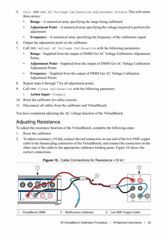
Adjusting ResistanceTo adjust the resistance function of the VirtualBench, complete the following steps:1. Reset the calibrator.2. To adjust resistance ≤19 kΩ, connect the red connectors on one end of the low EMF copper
cable to the banana plug connectors of the VirtualBench, and connect the connectors on the other end of the cable to the appropriate calibrator binding posts. Figure 10 shows the correct connections.
Figure 10. Cable Connections for Resistance ≤19 kΩ
1 VirtualBench DMM 2 Multifunction Calibrator 3 Low EMF Copper Cable
HI
LO
HI
LO
HVI
SENSEVΩ
OUTPUTVΩA
AUXCURRENT
GUARD GROUND
3
1 2

24 | ni.com | NI VirtualBench Calibration Procedure
3. Wait 2 minutes for the thermal EMF to stabilize.4. Call DMM Initialize Calibration with the following parameter:
• Password = NI (default)5. Call DMM Get Resistance Calibration Adjustment Points. This will return
two arrays:• Range—A numerical array specifying the range being calibrated• Adjustment Point—A numerical array specifying the resistance values required to
perform the adjustment6. Output the adjustment point on the calibrator with 2-wire compensation turned on.7. Call DMM Setup Resistance Calibration with the following parameter:
• Range—Supplied from DMM Get Resistance Calibration Adjustment Points8. Wait 5 seconds for settling.9. Call DMM Adjust Resistance Calibration with the following parameter:
• Adjustment Point—Resistance value returned by the calibrator10. Repeat steps 6 through 9 for the first four adjustment points.11. To adjust resistance >19 kΩ, output the adjustment point on the calibrator with 2-wire
compensation turned off.12. Call DMM Setup Resistance Calibration with the following parameter:
• Range—Supplied from DMM Get Resistance Calibration Adjustment Points13. Wait 5 seconds for settling.14. Call DMM Adjust Resistance Calibration with the following parameter:
• Adjustment Point—Resistance value returned by the calibrator15. Repeat steps 11 through 14 for the last eight adjustment points.16. Call DMM Close Calibration with the following parameter:
• Action Input = Commit17. Reset the calibrator for safety reasons.18. Disconnect all cables from the calibrator and VirtualBench.
You have completed adjusting the resistance function of the VirtualBench.

NI VirtualBench Calibration Procedure | © National Instruments | 25
Adjusting AC and DC CurrentTo adjust the AC and DC current functions of the VirtualBench, complete the following steps:1. Reset the calibrator.2. To adjust current ranges <1 A, connect the connectors on one end of the low EMF copper
cable to the VirtualBench mA and LO banana plug connectors, and connect the connectors on the other end of the cable to the HI and LO calibrator binding posts. Figure 11 shows the correct connections.
Figure 11. Cable Connections for Current Ranges <1 A
3. Wait 2 minutes for the thermal EMF to stabilize.4. Call DMM Initialize Calibration with the following parameter:
• Password = NI (default)5. Call DMM Get Current Calibration Adjustment Points. This will return two
arrays:• Range—A numerical array specifying the range being calibrated• Adjustment Point—A numerical array specifying the current required to perform the
adjustment6. Output the adjustment point on the calibrator.7. Call DMM Adjust Current Calibration with the following parameters:
• Range—Supplied from the output of DMM Get Current Calibration Adjustment Points
• Adjustment Point—Supplied from the output of DMM Get Current Calibration Adjustment Points
8. Repeat steps 6 through 7 for the first six adjustment points.
1 VirtualBench DMM 2 Multifunction Calibrator 3 Low EMF Copper Cable
HI
LO
HI
LO
HVI
SENSEVΩ
OUTPUTVΩA
AUXCURRENT
GUARD GROUND
1 2
3
26 | ni.com | NI VirtualBench Calibration Procedure
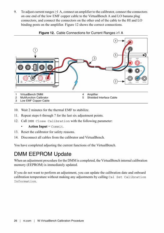
9. To adjust current ranges ≥1 A, connect an amplifier to the calibrator, connect the connectors on one end of the low EMF copper cable to the VirtualBench A and LO banana plug connectors, and connect the connectors on the other end of the cable to the HI and LO binding posts on the amplifier. Figure 12 shows the correct connections.
Figure 12. Cable Connections for Current Ranges ≥1 A
10. Wait 2 minutes for the thermal EMF to stabilize.11. Repeat steps 6 through 7 for the last six adjustment points.12. Call DMM Close Calibration with the following parameter:
• Action Input = Commit.13. Reset the calibrator for safety reasons.14. Disconnect all cables from the calibrator and VirtualBench.
You have completed adjusting the current functions of the VirtualBench.
DMM EEPROM UpdateWhen an adjustment procedure for the DMM is completed, the VirtualBench internal calibration memory (EEPROM) is immediately updated.
If you do not want to perform an adjustment, you can update the calibration date and onboard calibration temperature without making any adjustments by calling Cal Set Calibration Information.
1 VirtualBench DMM2 Multifunction Calibrator3 Low EMF Copper Cable
4 Amplifier5 Shielded Interface Cable
HI
LO
HI
LO
HVI
SENSEVΩ
OUTPUTVΩA
AUXCURRENT
GUARD GROUND
HI
LO
5
1
2
4
3

NI VirtualBench Calibration Procedure | © National Instruments | 27
DMM Re-VerificationRepeat the DMM Verification section to determine the As-Left status of the instrument.
Note If any test fails re-verification after performing an adjustment, verify that you have met the conditions listed in the DMM Test Conditions section before returning your device to NI. Refer to Where to Go for Support for assistance in returning the device to NI.
Oscilloscope Calibration ProcedureThis section contains the verification and adjustment procedures for the oscilloscope on the VirtualBench. The calibration process includes the following steps:1. Oscilloscope Initial Setup—Set up the test equipment.2. Oscilloscope Verification—Verify the existing operation of the instrument. This step
confirms whether the instrument is operating within its specified range prior to adjustment.3. Oscilloscope Adjustment—Perform an external adjustment of the instrument that adjusts
the calibration constants with respect to standards of known values.4. Oscilloscope Re-Verification—Repeat the verification procedure to ensure that the
instrument is operating within its specifications after adjustment.
These steps are described in more detail in the following sections.
Oscilloscope Test EquipmentTable 12 lists the equipment recommended for the oscilloscope performance verification and adjustment procedures. If the recommended equipment is not available, select a substitute using the requirements listed in the table.
Table 12. Recommended Equipment
EquipmentRecommended
Model Minimum Requirements
50 Ω terminator Amphenol 000-46650-51RFX
VB-8012 only.
Oscilloscope calibrator
Fluke 9500B calibrator
Vertical gain: DC ±(0.025% + 25 μV) into 1 MΩ
Oscilloscope calibrator active head
Fluke 9530 DC operation

28 | ni.com | NI VirtualBench Calibration Procedure
Oscilloscope Test ConditionsFollow these guidelines to optimize the equipment and the environment during calibration:• Keep connections to the device as short as possible. Long cables and wires act as antennae,
picking up noise that can affect measurements.• Use a USB connection between the PC and VirtualBench.• Verify that all connections to the device, including front panel connections, are secure.• Keep relative humidity between 10% and 80% noncondensing.• Allow a warm up time of at least 30 minutes to ensure that the VirtualBench is at a stable
operating temperature. • Plug the VirtualBench, PC, and the test equipment into the same power strip to avoid
ground loops.• Verification limits are defined assuming the same test equipment is used during verification
and adjustment.• Maintain an ambient temperature of 23 ±5 °C. The device temperature will be greater than
the ambient temperature.
Oscilloscope Initial Setup
Note This section is necessary for pre-adjustment verifications only. If you are performing a post-adjustment verification, skip the setup and go directly to the Oscilloscope Verification section.
To set up the test equipment, complete the following steps.1. If VirtualBench is running, shut down all instruments on the VirtualBench, and close the
VirtualBench software. Remove all signal connections.2. Verify that the oscilloscope calibrator has been calibrated within the time limits specified
in its specifications, and that a self-calibration has been performed before VirtualBench calibration. Consult the oscilloscope calibrator user documentation for instructions on calibrating these devices.
Function generator NI 5421 Must be able to generate a 1 kHz square wave between 36 mVpp and 18 Vpp with less than 200 ns rise time and less than 5% overshoot.
SMB to BNC cable NI part number 778827-01
Cable needed to connect from the function generator to the VirtualBench BNC connectors.
Table 12. Recommended Equipment (Continued)
EquipmentRecommended
Model Minimum Requirements

NI VirtualBench Calibration Procedure | © National Instruments | 29
Note Ensure that the VirtualBench is warmed up for at least 30 minutes and the calibrator is warmed up for the minimum time required as specified in its user documentation.
3. Verify that a self-calibration has been performed on the function generator before VirtualBench calibration.
Oscilloscope VerificationYou can use the verification procedure described in this section for both pre-adjustment and post-adjustment verification.
Verifying the Oscilloscope OffsetComplete the following steps to verify the VirtualBench oscilloscope offset.
Note In this procedure, the 50 Ω BNC terminator is only needed for the VB-8012. The VB-8034 and VB-8054 use an internal 50 Ω BNC terminator during calibration.
1. (VB-8012) Connect a 50 Ω BNC terminator to oscilloscope channel 1, as shown in Figure 13.(VB-8034/8054) Ensure there are no cables connected to any oscilloscope channels.
Figure 13. VB-8012 Oscilloscope Offset Channel 1 Connection Diagram
2. Call MSO Initialize.3. Call MSO Configure Timing with the following parameter:
• Sample Rate = 1M• Acquisition Time (s) = 0.1• Pretrigger Time (s) = 1e-9• Sampling Mode = Sample
1 VB-8012 Oscilloscope 2 50 Ω Terminator
1 2

30 | ni.com | NI VirtualBench Calibration Procedure
4. Call MSO Configure Analog Channel with the following parameters:• Enable Channel = TRUE• Channel = mso/1• Vertical Coupling = DC• Probe Attenuation = 1x• Vertical Range = 20• Vertical Offset = 0
5. Call MSO Run.6. Call MSO Read. Calculate and record the average analog waveform. Verify that this
measurement falls within the limits in Table 13.
7. Call MSO Stop.8. Repeat steps 4 to 7 for all of the ranges in Table 13.
Note The 0.02 V range only applies to the VB-8034 and VB-8054.
9. Call MSO Close.
Table 13. Oscilloscope Offset Verification Limits
Range (V)
Verification Point (V)
1 Year Limits (mV) 24 Hour Limits (mV)
Lower Upper Lower Upper
20 0 -400 400 -100 100
10 -200 200 -50 50
5 -100 100 -30 30
2 -40 40 -12 12
1 -20 20 -6 6
0.5 -10 10 -3 3
0.2 -4 4 -1.2 1.2
0.1 -2 2 -0.8 0.8
0.05 -1 1 -0.6 0.6
0.02* -0.4 0.4 -0.3 0.3
* VB-8034 and VB-8054 only.

NI VirtualBench Calibration Procedure | © National Instruments | 31
10. (VB-8012) Remove the 50 Ω BNC terminator from channel 1 and connect it to channel 2, as shown in Figure 14.
Figure 14. VB-8012 Oscilloscope Offset Channel 2 Connection Diagram
11. Repeat steps 2 to 9 for all ranges on channel 2.
Note When calling MSO Configure Analog Channel in step 4, change the Channel input to mso/2.
12. (VB-8012) Remove the 50 Ω BNC terminator from channel 2.13. (VB-8034/8054) Repeat steps 2 to 9 for all ranges on channel 3.
Note When calling MSO Configure Analog Channel in step 4, change the Channel input to mso/3.
14. (VB-8034/8054) Repeat steps 2 to 9 for all ranges on channel 4.
Note When calling MSO Configure Analog Channel in step 4, change the Channel input to mso/4.
1 VB-8012 Oscilloscope 2 50 Ω Terminator
1 2
32 | ni.com | NI VirtualBench Calibration Procedure
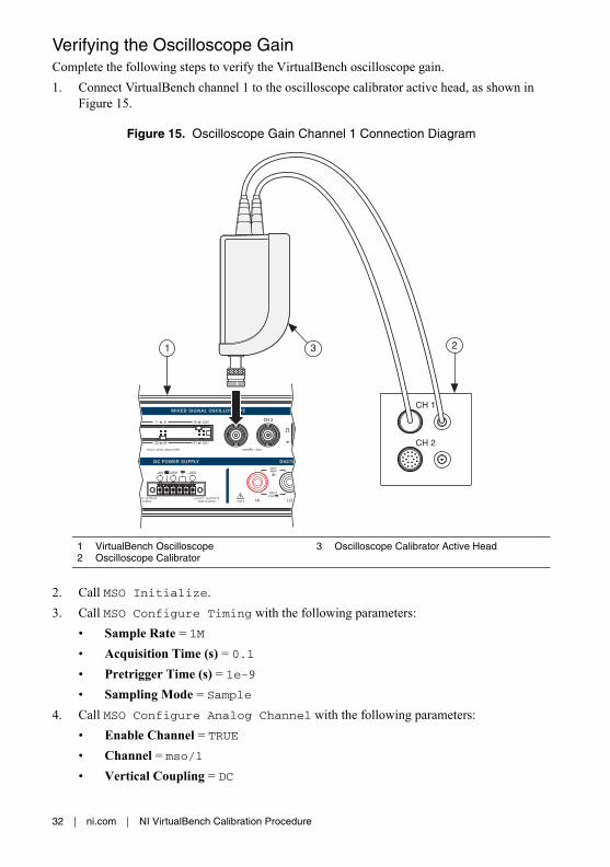
Verifying the Oscilloscope GainComplete the following steps to verify the VirtualBench oscilloscope gain.1. Connect VirtualBench channel 1 to the oscilloscope calibrator active head, as shown in
Figure 15.
Figure 15. Oscilloscope Gain Channel 1 Connection Diagram
2. Call MSO Initialize.3. Call MSO Configure Timing with the following parameters:
• Sample Rate = 1M• Acquisition Time (s) = 0.1• Pretrigger Time (s) = 1e-9• Sampling Mode = Sample
4. Call MSO Configure Analog Channel with the following parameters:• Enable Channel = TRUE• Channel = mso/1• Vertical Coupling = DC
1 VirtualBench Oscilloscope2 Oscilloscope Calibrator
3 Oscilloscope Calibrator Active Head
2
CH 2
CH 1
1 3

NI VirtualBench Calibration Procedure | © National Instruments | 33
• Probe Attenuation = 1x• Vertical Range = 20• Vertical Offset = 0
Note Configure the oscilloscope calibrator for high impedance loads.
5. Set the oscilloscope calibrator DC voltage output to -90% of the range, or -18 V. 6. Wait at least 5 seconds for the oscilloscope calibrator to settle.7. Call MSO Run.8. Call MSO Read. Calculate and record the average analog waveform. Save this value as
Vmeas_neg. 9. Set the oscilloscope calibrator DC voltage output to +90% of the range, or +18 V.10. Wait at least 5 seconds for the oscilloscope calibrator to settle.11. Call MSO Run.12. Call MSO Read. Calculate and record the average analog waveform. Save this value as
Vmeas_pos.13. Call MSO Stop.14. Calculate the gain error as follows:
Where Vpos and Vneg are listed in Table 14.Verify that this calculation falls within the limits in Table 14.
Table 14. Oscilloscope Gain Verification Limits
Range (V) Vpos (V) Vneg (V)
1 Year Limits (%) 24 Hour Limits (%)
Lower Upper Lower Upper
20 18 -18 -2 2 -0.8 0.8
10 9 -9 -2 2 -0.8 0.8
5 4.5 -4.5 -2 2 -0.8 0.8
2 1.8 -1.8 -2 2 -0.8 0.8
1 0.9 -0.9 -2 2 -0.8 0.8
0.5 0.45 -0.45 -2 2 -0.9 0.9
0.2 0.18 -0.18 -2 2 -0.9 0.9
0.1 0.09 -0.09 -2 2 -1 1
Vmeas_pos Vmeas_neg–( )Vpos Vneg–( )
--------------------------------------------------------- 1– 100%×

34 | ni.com | NI VirtualBench Calibration Procedure
15. Repeat steps 4 to 14 for all of the ranges with the values for Vpos and Vneg in Table 14.
Note The 0.02 V range only applies to the VB-8034 and VB-8054.
16. Call MSO Close.17. Remove the connections from channel 1. Connect VirtualBench channel 2 to the
oscilloscope calibrator active head, as shown in Figure 16.
Figure 16. Oscilloscope Gain Channel 2 Connection Diagram
0.05 0.045 -0.045 -2 2 -1 1
0.02* 0.018 -0.018 -2 2 -1.2 1.2
* VB-8034 and VB-8054 only.
1 VirtualBench Oscilloscope 2 Oscilloscope Calibrator 3 Oscilloscope Calibrator Active Head
Table 14. Oscilloscope Gain Verification Limits (Continued)
Range (V) Vpos (V) Vneg (V)
1 Year Limits (%) 24 Hour Limits (%)
Lower Upper Lower Upper
2
CH 2
CH 1
1 3
NI VirtualBench Calibration Procedure | © National Instruments | 35
18. Repeat steps 2 to 16 for all ranges on channel 2.
Note When calling MSO Configure Analog Channel in step 4, change the Channel input to mso/2.
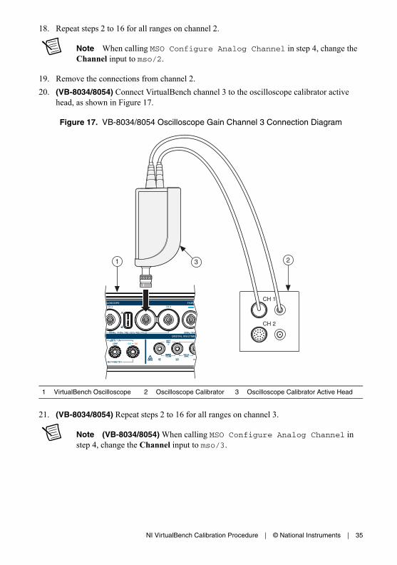
19. Remove the connections from channel 2. 20. (VB-8034/8054) Connect VirtualBench channel 3 to the oscilloscope calibrator active
head, as shown in Figure 17.
Figure 17. VB-8034/8054 Oscilloscope Gain Channel 3 Connection Diagram
21. (VB-8034/8054) Repeat steps 2 to 16 for all ranges on channel 3.
Note (VB-8034/8054) When calling MSO Configure Analog Channel in step 4, change the Channel input to mso/3.
1 VirtualBench Oscilloscope 2 Oscilloscope Calibrator 3 Oscilloscope Calibrator Active Head
2
CH 2
CH 1
1 3

36 | ni.com | NI VirtualBench Calibration Procedure
22. (VB-8034/8054) Remove the connections from channel 3. Connect VirtualBench channel 4 to the oscilloscope calibrator active head, as shown in Figure 18.
Figure 18. VB-8034/8054 Oscilloscope Gain Channel 4 Connection Diagram
23. (VB-8034/8054) Repeat steps 2 to 16 for all ranges on channel 4.
Note (VB-8034/8054) When calling MSO Configure Analog Channel in step 4, change the Channel input to mso/4.
24. (VB-8034/8054) Remove the connections from channel 4.
1 VirtualBench Oscilloscope 2 Oscilloscope Calibrator 3 Oscilloscope Calibrator Active Head
2
CH 2
CH 1
1 3

NI VirtualBench Calibration Procedure | © National Instruments | 37
Verifying the Oscilloscope Offset DAC GainComplete the following steps to verify the VirtualBench Oscilloscope Offset DAC Gain.1. Connect VirtualBench channel 1 to the oscilloscope calibrator active head, as shown in
Figure 19.
Figure 19. Oscilloscope Gain Channel 1 Connection Diagram
2. Call MSO Initialize.3. Call MSO Configure Timing with the following parameters:
• Sample Rate = 1M• Acquisition Time (s) = 0.1• Pretrigger Time (s) = 1e-9• Sampling Mode = Sample
1 VirtualBench Oscilloscope 2 Oscilloscope Calibrator 3 Oscilloscope Calibrator Active Head
2
CH 2
CH 1
1 3

38 | ni.com | NI VirtualBench Calibration Procedure
4. Call MSO Configure Analog Channel with the following parameters:• Enable Channel = TRUE• Channel = mso/1• Vertical Coupling = DC• Probe Attenuation = 1x• Vertical Range = 20• Vertical Offset = -18
5. Set the oscilloscope calibrator DC voltage output to the programmed vertical offset, or -18 V for this iteration.
6. Wait at least 5 seconds for the oscilloscope calibrator and DUT to settle.7. Call MSO Run.8. Call MSO Read. Calculate and record the average analog waveform. Save this value as
Vmeas_neg. 9. Call MSO Stop.10. Call MSO Configure Analog Channel with the following parameters:
• Enable Channel = TRUE• Channel = mso/1• Vertical Coupling = DC• Probe Attenuation = 1x• Vertical Range = 20• Vertical Offset = 18
11. Set the oscilloscope calibrator DC voltage output to the programmed vertical offset, or +18 V for this iteration.
12. Wait at least 5 seconds for the oscilloscope calibrator and DUT to settle.13. Call MSO Run.14. Call MSO Read. Calculate and record the average analog waveform. Save this value as
Vmeas_pos.15. Call MSO Stop.16. Calculate the gain error as follows:
Where Vpos and Vneg are listed in Table 15.Verify that this calculation falls within the limits in Table 15.
Vmeas_pos Vmeas_neg–( )Vpos Vneg–( )
--------------------------------------------------------- 1– 100%×

NI VirtualBench Calibration Procedure | © National Instruments | 39
17. Repeat steps 4 to 16 for all of the ranges with the values for Vpos and Vneg in Table 15.
Note When calling MSO Configure Analog Channel the Vertical Range input must match the range value in Table 15.
Note The 0.02 V vertical range only applies to the VB-8034 and VB-8054.
18. Call MSO Close.
Table 15. Oscilloscope Offset DAC Gain Verification Limits
Vertical Range (V)
Vertical Offset (V) 1 Year Limits (%) 24 Hour Limits (%)
Vpos Vneg Lower Upper Lower Upper
20 18 -18 -2 2 -1 1
10 -2 2 -0.7 0.7
5 -2 2 -0.5 0.5
2 -2 2 -0.5 0.5
1 -2 2 -0.5 0.5
0.5 -2 2 -0.5 0.5
0.2 4.5 -4.5 -2 2 -0.5 0.5
0.1 -2 2 -0.5 0.5
0.05 -2 2 -0.5 0.5
0.02* -2 2 -0.5 0.5
* VB-8034 and VB-8054 only.

40 | ni.com | NI VirtualBench Calibration Procedure
19. Remove the connections from channel 1. Connect VirtualBench channel 2 to the oscilloscope calibrator active head, as shown in Figure 20.
Figure 20. Oscilloscope Gain Channel 2 Connection Diagram
20. Repeat steps 2 to 18 for all ranges on channel 2.
Note When calling MSO Configure Analog Channel in step 4, change the Channel input to mso/2.
21. Remove the connections from channel 2.
1 VirtualBench Oscilloscope 2 Oscilloscope Calibrator 3 Oscilloscope Calibrator Active Head
2
CH 2
CH 1
1 3

NI VirtualBench Calibration Procedure | © National Instruments | 41
22. (VB-8034/8054) Connect VirtualBench channel 3 to the oscilloscope calibrator active head, as shown in Figure 21.
Figure 21. VB-8034/8054 Oscilloscope Gain Channel 3 Connection Diagram
23. (VB-8034/8054) Repeat steps 2 to 18 for all ranges on channel 3.
Note (VB-8034/8054) When calling MSO Configure Analog Channel in step 4, change the Channel input to mso/3.
1 VirtualBench Oscilloscope 2 Oscilloscope Calibrator 3 Oscilloscope Calibrator Active Head
2
CH 2
CH 1
1 3

42 | ni.com | NI VirtualBench Calibration Procedure
24. (VB-8034/8054) Remove the connections from channel 3. Connect VirtualBench channel 4 to the oscilloscope calibrator active head, as shown in Figure 22.
Figure 22. VB-8034/8054 Oscilloscope Gain Channel 4 Connection Diagram
25. (VB-8034/8054) Repeat steps 2 to 18 for all ranges on channel 4.
Note (VB-8034/8054) When calling MSO Configure Analog Channel in step 4, change the Channel input to mso/4.
26. (VB-8034/8054) Remove the connections from channel 4.
1 VirtualBench Oscilloscope 2 Oscilloscope Calibrator 3 Oscilloscope Calibrator Active Head
2
CH 2
CH 1
1 3

NI VirtualBench Calibration Procedure | © National Instruments | 43
Oscilloscope AdjustmentThis section explains how to adjust the VirtualBench oscilloscope. You can choose to perform these adjustment procedures with or without performing the verification procedures first.
Note NI recommends repeating the verification procedures after you perform these adjustment procedures. Re-verification ensures that the instrument you have calibrated is operating within specifications after adjustments.
Note Allow the VirtualBench to warm up for at least 30 minutes before adjusting.
To adjust the Oscilloscope accuracy perform the following steps:
Note In this procedure, the 50 Ω BNC terminator is only needed for the VB-8012. The VB-8034 and VB-8054 use an internal 50 Ω BNC terminator during calibration.
1. (VB-8012) Connect a 50 Ω BNC terminator to Oscilloscope channel 1, as shown in Figure 23.(VB-8034/8054) Ensure there are no cables connected to any oscilloscope channels.
Figure 23. VB-8012 Oscilloscope Adjustment Channel 1 Connection Diagram
2. Call MSO Initialize Calibration with the following parameter:• Password = NI (default)
3. Call MSO Adjust Offset Calibration with the following parameter:• Channel = mso/1
1 VB-8012 Oscilloscope 2 50 Ω Terminator
1 2

44 | ni.com | NI VirtualBench Calibration Procedure
4. (VB-8012) Disconnect the 50 Ω terminator5. Connect Channel 1 of the oscilloscope to Channel 0 of the function generator with the
BNC-to-SMB cable, as shown in Figure 24.
Figure 24. Oscilloscope Channel 1-to-Function Generator Connection Diagram
6. Call MSO Get Compensator Attenuation Calibration Adjustment Points. This will return three arrays:• Range—A numerical array specifying the range being calibrated• Amplitude—A numerical array specifying the square wave amplitude required for
calibration (Vpk-pk)• Frequency—A numerical array specifying the frequency of the calibration square
wave
Note Configure the function generator for high impedance loads.
7. Use the function generator to generate a square wave with the offset set to zero and duty cycle set to 50%; the frequency and amplitude are supplied from the output of MSO Get Compensator Attenuation Calibration Adjustment Points.
8. Wait 100 milliseconds.9. Call MSO Adjust Compensator Attenuation Calibration with the following
parameters:• Channel—mso/1
• Range—Supplied from the output of MSO Get Compensator Attenuation Calibration Adjustment Points
1 VirtualBench Oscilloscope 2 Function Generator 3 BNC-to-SMB Cable
CH 0
1
3
PFI 0
PFI 1
ACCESS ACTIVE
CLKIN
DIG
ITA
L D
ATA
& C
ON
TR
OL
2

NI VirtualBench Calibration Procedure | © National Instruments | 45
• Amplitude—Supplied from the output of MSO Get Compensator Attenuation Calibration Adjustment Points
• Frequency—Supplied from the output of MSO Get Compensator Attenuation Calibration Adjustment Points
10. Repeat steps 7 to 9 for each adjustment point.11. Disconnect the function generator. Connect VirtualBench channel 1 to the oscilloscope
calibrator active head, as shown in Figure 25.
Figure 25. Oscilloscope Gain Channel 1 Connection Diagram
12. Call MSO Get Range Calibration Adjustment Points. This will return two arrays:• Range—A numerical array specifying the range being calibrated• Adjustment Point—A numerical array specifying the DC voltage required to perform
the adjustment13. Use the oscilloscope calibrator to generate a DC voltage with the adjustment point supplied
from the output of MSO Get Range Calibration Adjustment Points.14. Wait 5 seconds.
1 VirtualBench Oscilloscope 2 Oscilloscope Calibrator 3 Oscilloscope Calibrator Active Head
2
CH 2
CH 1
1 3
46 | ni.com | NI VirtualBench Calibration Procedure
15. Call MSO Adjust Range Calibration with the following parameters:• Channel—mso/1
• Range—Supplied from the output of MSO Get Range Calibration Adjustment Points• Adjustment Point—Supplied from the output of MSO Get Range Calibration
Adjustment Points16. Repeat steps 13 to 15 for each adjustment point.17. Call MSO Get Offset DAC Calibration Adjustment Points. This will return
two arrays:• Range—A numerical array specifying the range being calibrated• Adjustment Point—A numerical array specifying the DC voltage required to perform
the adjustment18. Use the oscilloscope calibrator to generate a DC voltage with the adjustment point supplied
from the output of MSO Get Offset DAC Calibration Adjustment Points.19. Wait 5 seconds.20. Call MSO Adjust Offset DAC Calibration with the following parameters:
• Channel—mso/1
• Range—A numerical array specifying the range being calibrated• Adjustment Point—A numerical array specifying the DC voltage required to perform
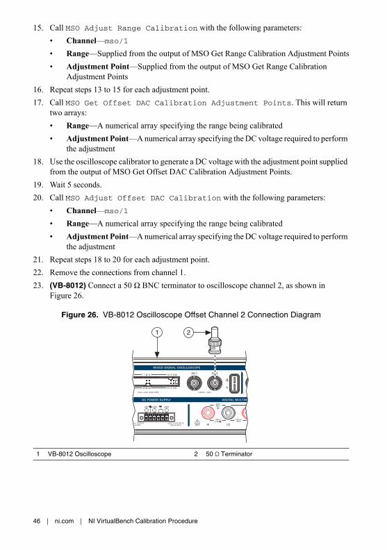
the adjustment21. Repeat steps 18 to 20 for each adjustment point.22. Remove the connections from channel 1. 23. (VB-8012) Connect a 50 Ω BNC terminator to oscilloscope channel 2, as shown in
Figure 26.
Figure 26. VB-8012 Oscilloscope Offset Channel 2 Connection Diagram
1 VB-8012 Oscilloscope 2 50 Ω Terminator
1 2

NI VirtualBench Calibration Procedure | © National Instruments | 47
24. Repeat steps 3 to 21 for MSO channel 2.
Note For all inputs, change the Channel input to mso/2.
25. (VB-8012) Skip to step 28.26. (VB-8034/8054) Repeat steps 3 to 21 for MSO channel 3.
Note (VB-8034/8054) For all inputs, change the Channel input to mso/3.
27. (VB-8034/8054) Repeat steps 3 to 21 for MSO channel 4.
Note (VB-8034/8054) For all inputs, change the Channel input to mso/4.
28. Call MSO Close Calibration with the following parameter:• Action = Commit
You have completed adjusting the VirtualBench oscilloscope. It is recommended that a post-adjustment verification be performed.
Oscilloscope EEPROM UpdateWhen an adjustment procedure for the oscilloscope is completed, the VirtualBench internal calibration memory (EEPROM) is immediately updated.
If you do not want to perform an adjustment, you can update the calibration date and onboard calibration temperature without making any adjustments by calling Cal Set Calibration Information.
Oscilloscope Re-VerificationRepeat the Oscilloscope Verification section to determine the As-Left status of the instrument.
Note If any test fails re-verification after performing an adjustment, verify that you have met the conditions listed in the Oscilloscope Test Conditions section before returning your device to NI. Refer to Where to Go for Support for assistance in returning the device to NI.
Function Generator (FGEN) Calibration ProcedureThis section contains the verification and adjustment procedures for the FGEN on the VirtualBench. The calibration process includes the following steps:1. FGEN Initial Setup—Set up the test equipment.2. FGEN Verification—Verify the existing operation of the instrument. This step confirms
whether the instrument is operating within its specified range prior to adjustment.

48 | ni.com | NI VirtualBench Calibration Procedure
3. FGEN Adjustment—Perform an external adjustment of the instrument that adjusts the calibration constants with respect to standards of known values.
4. FGEN Re-Verification—Repeat the verification procedure to ensure that the instrument is operating within its specifications after adjustment.
These steps are described in more detail in the following sections.
FGEN Test EquipmentTable 16 lists the equipment recommended for the FGEN performance verification and adjustment procedures. If the recommended equipment is not available, select a substitute using the requirements listed in the table.
FGEN Test ConditionsFollow these guidelines to optimize the equipment and the environment during calibration:• Keep connections to the device as short as possible. Long cables and wires act as antennae,
picking up noise that can affect measurements.• Use a USB connection between the PC and VirtualBench.• Verify that all connections to the device, including front panel connections, are secure.• Keep relative humidity between 10% and 80% noncondensing.• Allow a warmup time of at least 30 minutes to ensure that the VirtualBench is at a stable
operating temperature. • Plug the VirtualBench, PC, and the test equipment into the same power strip to avoid
ground loops.• Verification limits are defined assuming the same test equipment is used during verification
and adjustment.• Maintain an ambient temperature of 23 ±5 °C. The device temperature will be greater than
the ambient temperature.
Table 16. Recommended Equipment
EquipmentRecommended
Model Minimum Requirements
Digital multimeter (DMM)
NI PXI-4071 DC V accuracy: 21 ppmDC input impedance: ≥1 GΩDC A accuracy: 310 ppm
Banana plug-to-BNC cable
Pomona 4530-C —

NI VirtualBench Calibration Procedure | © National Instruments | 49
FGEN Initial Setup
Note This section is necessary for pre-adjustment verifications only. If you are performing a post-adjustment verification, skip the setup and go directly to the Verifying the FGEN Offset section.
To set up the test equipment, complete the following steps.1. If VirtualBench is running, shut down all instruments on the VirtualBench, and close the
VirtualBench software. Remove all signal connections.2. Verify that the DMM has been calibrated within the proper calibration interval specified in
its specifications, and a self-calibration is performed.
Note Ensure that the VirtualBench is warmed up for at least 30 minutes and the DMM is warmed up for the minimum time required as specified in its user documentation.
FGEN VerificationYou can use the verification procedure described in this section for both pre-adjustment and post-adjustment verification.
Verifying the FGEN OffsetComplete the following steps to verify the VirtualBench FGEN offset.1. Connect the voltage input HI and LO terminals of the DMM to the FGEN BNC using a
banana plug-to-BNC cable—observing the polarity of the banana plugs—as shown in Figure 27.
Figure 27. Cable Connections for FGEN Verification and Adjustment
1 VirtualBench FGEN 2 DMM 3 Banana Plug-to-BNC Cable
HI
LO
300VMAX
AMPS
500V MAX
HI
LO
1kVMAX
3A, 250VMAX
INPUT MAX1kV
1
3
2
50 | ni.com | NI VirtualBench Calibration Procedure
2. Call FGEN Initialize.3. Call FGEN Configure Standard Waveform with the following parameters:
• Waveform Function = DC• DC Offset = 0
4. Call FGEN Enable Filter with the following parameter:• Enable Filter = TRUE
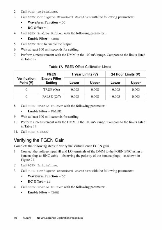
5. Call FGEN Run to enable the output.6. Wait at least 100 milliseconds for settling.7. Perform a measurement with the DMM in the 100 mV range. Compare to the limits listed
in Table 17.
8. Call FGEN Enable Filter with the following parameter:• Enable Filter = FALSE
9. Wait at least 100 milliseconds for settling.10. Perform a measurement with the DMM in the 100 mV range. Compare to the limits listed
in Table 17.11. Call FGEN Close.
Verifying the FGEN GainComplete the following steps to verify the VirtualBench FGEN gain.1. Connect the voltage input HI and LO terminals of the DMM to the FGEN BNC using a
banana plug-to-BNC cable—observing the polarity of the banana plugs—as shown in Figure 27.
2. Call FGEN Initialize.3. Call FGEN Configure Standard Waveform with the following parameters:
• Waveform Function = DC• DC Offset = 12
4. Call FGEN Enable Filter with the following parameter:• Enable Filter = TRUE
Table 17. FGEN Offset Calibration Limits
Verification Point (V)
FGEN Enable Filter
Setting
1 Year Limits (V) 24 Hour Limits (V)
Lower Upper Lower Upper
0 TRUE (On) -0.008 0.008 -0.003 0.003
0 FALSE (Off) -0.008 0.008 -0.003 0.003

NI VirtualBench Calibration Procedure | © National Instruments | 51
5. Wait at least 100 milliseconds for settling.6. Call FGEN Run.7. Perform a measurement with the DMM in the best available range greater than 12 V.
Compare to the limits listed in Table 18.
8. Call FGEN Enable Filter with the following parameter:• Enable Filter = FALSE
9. Wait at least 100 milliseconds for settling.10. Perform a measurement with the DMM in the best available range greater than 12 V.
Compare to the limits listed in Table 18.11. Repeat steps 3 through 10 for all verification points in Table 18.12. Call FGEN Close.
FGEN AdjustmentThis section explains how to adjust the VirtualBench FGEN. You can choose to perform these adjustment procedures with or without performing the verification procedures first.
Note NI recommends repeating the verification procedures after you perform these adjustment procedures. Re-verification ensures that the instrument you have calibrated is operating within specifications after adjustments.
Note Before adjustment perform a self-calibration on the DMM performing the adjustment.
Note Allow the VirtualBench to warm up for at least 30 minutes before adjusting.
Table 18. FGEN Gain Calibration Limits
Verification Point (V)
FGEN Enable Filter
Setting
1 Year Limits (V) 24 Hour Limits (V)
Lower Upper Lower Upper
+12 TRUE (On) 11.88 12.12 11.98 12.02
FALSE (Off) 11.88 12.12 11.98 12.02
-12 TRUE (On) -12.12 -11.88 -12.02 -11.98
FALSE (Off) -12.12 -11.88 -12.02 -11.98

52 | ni.com | NI VirtualBench Calibration Procedure
To adjust the FGEN accuracy complete the following steps.1. Connect the voltage input HI and LO terminals of the DMM to the FGEN BNC using a
banana plug-to-BNC cable—observing the polarity of the banana plugs—as shown in Figure 28.
Figure 28. Cable Connections for FGEN Verification and Adjustment
2. Call FGEN Initialize Calibration with the following parameter:• Password = NI (default)
3. Call FGEN Setup Offset Calibration with the following parameter:• Enable Filter = TRUE
4. Wait 100 milliseconds.5. Perform a measurement with the DMM in the 1 V range. Record the reference value
measurement.6. Call FGEN Adjust Offset Calibration with the following parameter:
• Reference Value—Supplied from measurement in step 57. Repeat steps 3 through 6 until FGEN Adjust Offset Calibration returns TRUE
from its Calibration Done output.8. Repeat steps 3 through 7 with the following parameter:
• Enable Filter = FALSE9. Call FGEN Get Gain Calibration Adjustment Points. This will return
two arrays:• Enable Filter—A Boolean array of filter settings• Adjustment Point—An array of voltage points used in the gain adjustment steps
1 VirtualBench FGEN 2 DMM 3 Banana Plug-to-BNC Cable
HI
LO
300VMAX
AMPS
500V MAX
HI
LO
1kVMAX
3A, 250VMAX
INPUT MAX1kV
1
3
2

NI VirtualBench Calibration Procedure | © National Instruments | 53
10. Call FGEN Setup Gain Calibration with the following parameters:• Enable Filter—Supplied from the output of FGEN Get Gain Calibration Adjustment
Points• Adjustment Point—Supplied from the output of FGEN Get Gain Calibration
Adjustment Points11. Wait 100 milliseconds.12. Perform a measurement with the DMM in a range greater than 12 V. Record the reference
value measurement.13. Call FGEN Adjust Gain Calibration with the following parameter:
• Reference Value—Supplied from measurement in step 1214. Repeat steps 10 through 13 for all adjustment points.15. Call FGEN Close Calibration with the following parameter:
• Action = Commit
You have completed adjusting the VirtualBench FGEN. It is recommended that you perform a post-adjustment verification.
FGEN EEPROM UpdateWhen an adjustment procedure for the FGEN is completed, the VirtualBench internal calibration memory (EEPROM) is immediately updated.
If you do not want to perform an adjustment, you can update the calibration date and onboard calibration temperature without making any adjustments by calling Cal Set Calibration Information.
FGEN Re-VerificationRepeat the FGEN Verification section to determine the As-Left status of the instrument.
Note If any test fails re-verification after performing an adjustment, verify that you have met the conditions listed in the FGEN Test Conditions section before returning your device to NI. Refer to Where to Go for Support for assistance in returning the device to NI.
DC Power Supply Calibration ProcedureThis section contains the verification and adjustment procedures for the DC power supply on the VirtualBench. The calibration process includes the following steps:1. DC Power Supply Initial Setup—Set up the test equipment.2. DC Power Supply Verification—Verify the existing operation of the instrument. This step
confirms whether the instrument is operating within its specified range prior to adjustment.

54 | ni.com | NI VirtualBench Calibration Procedure
3. DC Power Supply Adjustment—Perform an external adjustment of the instrument that adjusts the calibration constants with respect to standards of known values.
4. DC Power Supply Re-Verification—Repeat the verification procedure to ensure that the instrument is operating within its specifications after adjustment.
These steps are described in more detail in the following sections.
Note If you are calibrating both the DMM and the DC power supply, the DMM must be calibrated first.
DC Power Supply Test EquipmentTable 19 lists the equipment recommended for the DC power supply performance verification and adjustment procedures. If the recommended equipment is not available, select a substitute using the requirements listed in the table.
DC Power Supply Test ConditionsFollow these guidelines to optimize the equipment and the environment during calibration:• Keep connections to the device as short as possible. Long cables and wires act as antennae,
picking up noise that can affect measurements.• Use a USB connection between the PC and VirtualBench.• Verify that all connections to the device, including front panel connections, are secure.• Use shielded copper wire for all cable connections. Use twisted-pair, shielded wire to
reduce measurement error in noisy environments.• Keep relative humidity between 10% and 80% noncondensing.• Allow a warm up time of at least 30 minutes to ensure that the VirtualBench is at a stable
operating temperature.
Table 19. Recommended Equipment
EquipmentRecommended
Model Minimum Requirements
Digital multimeter (DMM)
NI PXI-4071 DC V accuracy: 21 ppm at 25 VDC input impedance: ≥1 GΩDC A accuracy: 310 ppm at 1 A, 460 ppm at 2 A
Cabling wire — 18 AWG to 22 AWG. Twisted pair, shielded cabling wire is recommended

NI VirtualBench Calibration Procedure | © National Instruments | 55
• Plug the VirtualBench, PC, and the test equipment into the same power strip to avoid ground loops.
• Verification limits are defined assuming the same test equipment is used during verification and adjustment.
• Maintain an ambient temperature of 23 ±5 °C. The device temperature will be greater than the ambient temperature.
DC Power Supply Initial Setup
Note This section is necessary for pre-adjustment verifications only. If you are performing a post-adjustment verification, skip the setup and go directly to the DC Power Supply Verification section.
To set up the test equipment, complete the following steps:1. If VirtualBench is running, shut down all instruments on the VirtualBench, and close the
VirtualBench software. Remove all signal connections.2. Verify that the DMM has been calibrated within the proper calibration interval specified in
its specifications, and a self-calibration is performed.
Note Ensure that the VirtualBench is warmed up for at least 30 minutes and the DMM is warmed up for the minimum time required as specified in its user documentation.
Note Before verifying or adjusting the DC power supply, you must enable and set the output voltages at full scale for a minimum of 15 minutes.
Note If you are calibrating both the DMM and the DC power supply, the DMM must be calibrated first.
DC Power Supply VerificationYou can use the verification procedure described in this section for both pre-adjustment and post-adjustment verification.
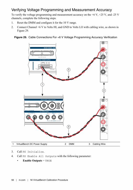
56 | ni.com | NI VirtualBench Calibration Procedure
Verifying Voltage Programming and Measurement AccuracyTo verify the voltage programming and measurement accuracy on the +6 V, +25 V, and -25 V channels, complete the following steps.1. Reset the DMM and configure it for the 10 V range.2. Connect Channel +6 V to Volts HI, and GND to Volts LO with cabling wire, as shown in
Figure 29.
Figure 29. Cable Connections For +6 V Voltage Programming Accuracy Verification
3. Call PS Initialize.4. Call PS Enable All Outputs with the following parameter:
• Enable Outputs = TRUE
1 VirtualBench DC Power Supply 2 DMM 3 Cabling Wire
HI
LO
300VMAX
AMPS
500V MAX
HI
LO
1kVMAX
3A, 250VMAX
INPUT MAX1kV
1
3
3
HI
LO
300VMAX
AMPS
500V MAX
HI
LO
1kVMAX
3A, 250VMAX
INPUT MAX1kV
2

NI VirtualBench Calibration Procedure | © National Instruments | 57
5. Call PS Configure Voltage Output with the following parameters:• Channel = ps/+6V• Voltage Level = 0, as listed in the first row of the Verification Point column of
Table 20 or 21• Current Limit = 1 or 3, as listed in the first row of the Current Limit column of
Table 20 or 216. Wait at least 150 milliseconds for the DC power supply to settle.7. Measure the output voltage with the DMM and record the reading. Subtract the DMM
reading from the verification point. Verify that the calculation falls between the limits in Table 20 or 21.
Table 20. VB-8012 DC Power Supply Voltage Programming and Measurement Accuracy
ChannelVerification
Point (V)Current Limit (A) 1 Year Limits ±(V)
24 Hour Limits ±(V)
+6 V 0 1 0.0050 0.0020
1.5 0.0065 0.0024
3 0.0080 0.0028
4.5 0.0095 0.0031
6 0.0110 0.0035
+25 V 0 0.5 0.0200 0.0080
6.5 0.0265 0.0096
12.5 0.0325 0.0111
18.75 0.0388 0.0127
25 0.0450 0.0143
-25 V 0 0.5 0.0200 0.0080
-6.5 0.0265 0.0096
-12.5 0.0325 0.0111
-18.75 0.0388 0.0127
-25 0.0450 0.0143
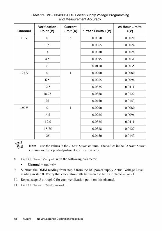
58 | ni.com | NI VirtualBench Calibration Procedure
Note Use the values in the 1 Year Limits column. The values in the 24 Hour Limits column are for a post-adjustment verification only.
8. Call PS Read Output with the following parameter:• Channel = ps/+6V
9. Subtract the DMM reading from step 7 from the DC power supply Actual Voltage Level reading in step 8. Verify that calculation falls between the limits in Table 20 or 21.
10. Repeat steps 5 through 9 for each verification point on this channel.11. Call PS Reset Instrument.
Table 21. VB-8034/8054 DC Power Supply Voltage Programming and Measurement Accuracy
ChannelVerification
Point (V)Current Limit (A) 1 Year Limits ±(V)
24 Hour Limits ±(V)
+6 V 0 3 0.0050 0.0020
1.5 0.0065 0.0024
3 0.0080 0.0028
4.5 0.0095 0.0031
6 0.0110 0.0035
+25 V 0 1 0.0200 0.0080
6.5 0.0265 0.0096
12.5 0.0325 0.0111
18.75 0.0388 0.0127
25 0.0450 0.0143
-25 V 0 1 0.0200 0.0080
-6.5 0.0265 0.0096
-12.5 0.0325 0.0111
-18.75 0.0388 0.0127
-25 0.0450 0.0143

NI VirtualBench Calibration Procedure | © National Instruments | 59
12. Disconnect all connections and connect Channel +25 V to Volts HI and GND and Common Floating GND to Volts LO as shown in Figure 30.
Figure 30. Cable Connections For +25 V Voltage Programming Accuracy Verification
13. Configure the DMM for the 100 V range.14. Repeat steps 4 through 11 for the ps/+25V channel
1 VirtualBench DC Power Supply 2 DMM 3 Cabling Wire
1
3
3
HI
LO
300VMAX
AMPS
500V MAX
HI
LO
1kVMAX
3A, 250VMAX
INPUT MAX1kV
2
HI
LO
300VMAX
AMPS
500V MAX
HI
LO
1kVMAX
3A, 250VMAX
INPUT MAX1kV

60 | ni.com | NI VirtualBench Calibration Procedure
15. Disconnect all connections and connect Channel -25 V to Volts HI, and GND to Volts LO as shown in Figure 31. Connect GND and Common Floating GND with a jumper.
Figure 31. Cable Connections For -25 V Voltage Programming Accuracy Verification
16. Repeat steps 4 through 11 for the ps/-25V channel.17. Disconnect all connections.18. Call PS Close.
1 VirtualBench DC Power Supply 2 DMM 3 Cabling Wire
1
3
3
2
HI
LO
300VMAX
AMPS
500V MAX
HI
LO
1kVMAX
3A, 250VMAX
INPUT MAX1kV
HI
LO
300VMAX
AMPS
500V MAX
HI
LO
1kVMAX
3A, 250VMAX
INPUT MAX1kV

NI VirtualBench Calibration Procedure | © National Instruments | 61
Verifying Current Programming and Measurement AccuracyTo verify the current programming and measurement accuracy of the DC power supply, complete the following steps.1. Reset the DMM and configure it for the 1 A range for the VB-8012 or the 3 A range for the
VB-8034/8054.2. Connect Channel +6 V to Amps HI, and GND to Amps LO as shown in Figure 32.
Figure 32. Cable Connections For +6 V Current Programming Accuracy Verification
3. Call PS Initialize.4. Call PS Enable All Outputs with the following parameter:
• Enable Outputs = TRUE
1 VirtualBench DC Power Supply 2 DMM 3 Cabling Wire
1
3
3
2
HI
LO
300VMAX
AMPS
500V MAX
HI
LO
1kVMAX
3A, 250VMAX
INPUT MAX1kV
HI
LO
300VMAX
AMPS
500V MAX
HI
LO
1kVMAX
3A, 250VMAX
INPUT MAX1kV
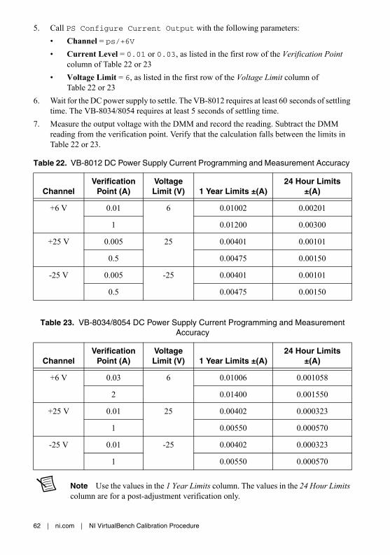
62 | ni.com | NI VirtualBench Calibration Procedure
5. Call PS Configure Current Output with the following parameters:• Channel = ps/+6V• Current Level = 0.01 or 0.03, as listed in the first row of the Verification Point
column of Table 22 or 23• Voltage Limit = 6, as listed in the first row of the Voltage Limit column of
Table 22 or 236. Wait for the DC power supply to settle. The VB-8012 requires at least 60 seconds of settling
time. The VB-8034/8054 requires at least 5 seconds of settling time.7. Measure the output voltage with the DMM and record the reading. Subtract the DMM
reading from the verification point. Verify that the calculation falls between the limits in Table 22 or 23.
Note Use the values in the 1 Year Limits column. The values in the 24 Hour Limits column are for a post-adjustment verification only.
Table 22. VB-8012 DC Power Supply Current Programming and Measurement Accuracy
ChannelVerification
Point (A)Voltage Limit (V) 1 Year Limits ±(A)
24 Hour Limits ±(A)
+6 V 0.01 6 0.01002 0.00201
1 0.01200 0.00300
+25 V 0.005 25 0.00401 0.00101
0.5 0.00475 0.00150
-25 V 0.005 -25 0.00401 0.00101
0.5 0.00475 0.00150
Table 23. VB-8034/8054 DC Power Supply Current Programming and Measurement Accuracy
ChannelVerification
Point (A)Voltage Limit (V) 1 Year Limits ±(A)
24 Hour Limits ±(A)
+6 V 0.03 6 0.01006 0.001058
2 0.01400 0.001550
+25 V 0.01 25 0.00402 0.000323
1 0.00550 0.000570
-25 V 0.01 -25 0.00402 0.000323
1 0.00550 0.000570

NI VirtualBench Calibration Procedure | © National Instruments | 63
8. Call PS Read Output with the following parameter:• Channel = ps/+6V
9. Subtract the DMM reading from step 7 from the DC power supply Actual Current Level reading in step 8. Verify that calculation falls between the limits in Table 22 or 23.
10. Repeat steps 5 through 9 for each verification point on this channel.11. Call PS Reset Instrument.12. Disconnect all connections and connect Channel +25 V to Amps HI, and Common Floating
GND to Amps LO as shown in Figure 33. Connect GND and Common Floating GND with a jumper.
Figure 33. Cable Connections For +25 V Current Programming Accuracy Verification
13. Repeat steps 5 through 11 for the ps/+25V channel.
1 VirtualBench DC Power Supply 2 DMM 3 Cabling Wire
1
3
3
2
HI
LO
300VMAX
AMPS
500V MAX
HI
LO
1kVMAX
3A, 250VMAX
INPUT MAX1kV
HI
LO
300VMAX
AMPS
500V MAX
HI
LO
1kVMAX
3A, 250VMAX
INPUT MAX1kV

64 | ni.com | NI VirtualBench Calibration Procedure
14. Disconnect all connections and connect Channel -25 V to Amps LO, and Common Floating GND to Amps HI as shown in Figure 34. Connect GND and Common Floating GND with a jumper.
Figure 34. Cable Connections For -25 V Current Programming Accuracy Verification
15. Repeat steps 5 through 11 for the ps/-25V channel.16. Disconnect all connections.17. Call PS Close.
If the instrument has successfully passed all verification tests, the DC power supply is within the published specifications, and adjustment is optional.
1 VirtualBench DC Power Supply 2 DMM 3 Cabling Wire
1
3
3
2
HI
LO
300VMAX
AMPS
500V MAX
HI
LO
1kVMAX
3A, 250VMAX
INPUT MAX1kV
HI
LO
300VMAX
AMPS
500V MAX
HI
LO
1kVMAX
3A, 250VMAX
INPUT MAX1kV

NI VirtualBench Calibration Procedure | © National Instruments | 65
DC Power Supply AdjustmentThis section explains how to adjust the VirtualBench DC power supply. You can choose to perform these adjustment procedures with or without performing the verification procedures first.
Note NI recommends repeating the verification procedures after you perform these adjustment procedures. Re-verification ensures that the instrument you have calibrated is operating within specifications after adjustments.
Note Before adjustment perform a self-calibration on the DMM performing the adjustment.
Note Allow the VirtualBench to warm up for at least 30 minutes before adjusting.
Note Before adjusting the DC power supply, you must enable and set the output voltages at full scale for a minimum of 15 minutes.
Adjusting Voltage Programming and Measurement AccuracyComplete the following steps to adjust voltage programming and measurement accuracy of VirtualBench.1. Reset the DMM.2. Call PS Initialize Calibration with the following parameters:
• Cal Type = Voltage • Password = NI (default)
3. Connect Channel +6 V to Volts HI, and GND to Volts LO as shown in Figure 35.
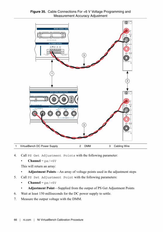
66 | ni.com | NI VirtualBench Calibration Procedure
Figure 35. Cable Connections For +6 V Voltage Programming and Measurement Accuracy Adjustment
4. Call PS Get Adjustment Points with the following parameter:• Channel = ps/+6VThis will return an array:• Adjustment Points—An array of voltage points used in the adjustment steps
5. Call PS Set Adjustment Point with the following parameters:• Channel = ps/+6V• Adjustment Point—Supplied from the output of PS Get Adjustment Points
6. Wait at least 150 milliseconds for the DC power supply to settle. 7. Measure the output voltage with the DMM.
1 VirtualBench DC Power Supply 2 DMM 3 Cabling Wire
HI
LO
300VMAX
AMPS
500V MAX
HI
LO
1kVMAX
3A, 250VMAX
INPUT MAX1kV
1
3
3
HI
LO
300VMAX
AMPS
500V MAX
HI
LO
1kVMAX
3A, 250VMAX
INPUT MAX1kV
2

NI VirtualBench Calibration Procedure | © National Instruments | 67
8. Call PS Measure Adjustment Point with the following parameters:• Channel = ps/+6V• Reference Value—Supplied from the DMM measurement in step 7
9. Repeat steps 5 through 8 for each adjustment point on this channel.10. Disconnect all connections and connect Channel +25 V to Volts HI, and Common Floating
GND to Volts LO as shown in Figure 36. Connect GND and Common Floating GND with a jumper.
Figure 36. Cable Connections For +25 V Voltage Programming and Measurement Accuracy Adjustment
11. Repeat steps 4 through 9 for the ps/+25V channel.
1 VirtualBench DC Power Supply 2 DMM 3 Cabling Wire
1
3
3
HI
LO
300VMAX
AMPS
500V MAX
HI
LO
1kVMAX
3A, 250VMAX
INPUT MAX1kV
2
HI
LO
300VMAX
AMPS
500V MAX
HI
LO
1kVMAX
3A, 250VMAX
INPUT MAX1kV

68 | ni.com | NI VirtualBench Calibration Procedure
12. Disconnect all connections and connect Channel -25 V to Volts HI, and Common Floating GND to Volts LO as shown in Figure 37. Connect GND and Common Floating GND with a jumper.
Figure 37. Cable Connections For -25 V Voltage Programming and Measurement Accuracy Adjustment
13. Repeat steps 4 through 9 for the ps/-25V channel.14. Call PS Close Calibration with the following parameter:
• Action = Commit15. Disconnect all connections.
1 VirtualBench DC Power Supply 2 DMM 3 Cabling Wire
1
3
3
2
HI
LO
300VMAX
AMPS
500V MAX
HI
LO
1kVMAX
3A, 250VMAX
INPUT MAX1kV
HI
LO
300VMAX
AMPS
500V MAX
HI
LO
1kVMAX
3A, 250VMAX
INPUT MAX1kV
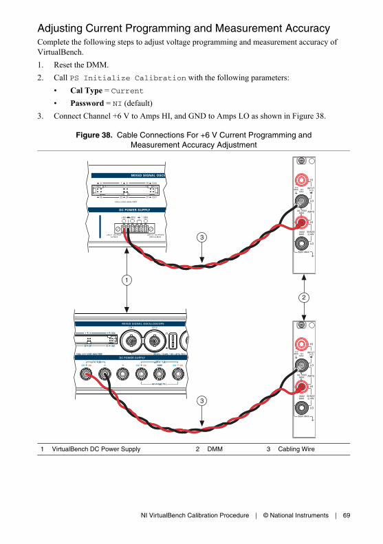
NI VirtualBench Calibration Procedure | © National Instruments | 69
Adjusting Current Programming and Measurement AccuracyComplete the following steps to adjust voltage programming and measurement accuracy of VirtualBench.1. Reset the DMM.2. Call PS Initialize Calibration with the following parameters:
• Cal Type = Current • Password = NI (default)
3. Connect Channel +6 V to Amps HI, and GND to Amps LO as shown in Figure 38.
Figure 38. Cable Connections For +6 V Current Programming and Measurement Accuracy Adjustment
1 VirtualBench DC Power Supply 2 DMM 3 Cabling Wire
1
3
3
2
HI
LO
300VMAX
AMPS
500V MAX
HI
LO
1kVMAX
3A, 250VMAX
INPUT MAX1kV
HI
LO
300VMAX
AMPS
500V MAX
HI
LO
1kVMAX
3A, 250VMAX
INPUT MAX1kV

70 | ni.com | NI VirtualBench Calibration Procedure
4. Call PS Get Adjustment Points with the following parameter:• Channel = ps/+6VThis will return an array:• Adjustment Points—An array of current points used in the adjustment steps
5. Call PS Set Adjustment Point with the following parameters:• Channel = ps/+6V• Adjustment Point—Supplied from the output of PS Get Adjustment Points
6. Wait for the DC power supply to settle. The VB-8012 requires at least 60 seconds of settling time. The VB-8034/8054 requires at least 5 seconds of settling time.
7. Measure the output current with the DMM.8. Call PS Measure Adjustment Point with the following parameters:
• Channel = ps/+6V• Reference Value—Supplied from the DMM measurement in step 7
9. Repeat steps 5 through 8 for each adjustment point on this channel.

NI VirtualBench Calibration Procedure | © National Instruments | 71
10. Disconnect all connections and connect Channel +25 V to Amps HI, and Common Floating GND to Amps LO as shown in Figure 39. Connect GND and Common Floating GND with a jumper.
Figure 39. Cable Connections For +25 V Current Programming and Measurement Accuracy Adjustment
11. Repeat steps 4 through 9 for the ps/+25V channel.
1 VirtualBench DC Power Supply 2 DMM 3 Cabling Wire
1
3
3
2
HI
LO
300VMAX
AMPS
500V MAX
HI
LO
1kVMAX
3A, 250VMAX
INPUT MAX1kV
HI
LO
300VMAX
AMPS
500V MAX
HI
LO
1kVMAX
3A, 250VMAX
INPUT MAX1kV
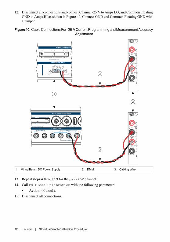
72 | ni.com | NI VirtualBench Calibration Procedure
12. Disconnect all connections and connect Channel -25 V to Amps LO, and Common Floating GND to Amps HI as shown in Figure 40. Connect GND and Common Floating GND with a jumper.
Figure 40. Cable Connections For -25 V Current Programming and Measurement Accuracy Adjustment
13. Repeat steps 4 through 9 for the ps/-25V channel.14. Call PS Close Calibration with the following parameter:
• Action = Commit15. Disconnect all connections.
1 VirtualBench DC Power Supply 2 DMM 3 Cabling Wire
1
3
3
2
HI
LO
300VMAX
AMPS
500V MAX
HI
LO
1kVMAX
3A, 250VMAX
INPUT MAX1kV
HI
LO
300VMAX
AMPS
500V MAX
HI
LO
1kVMAX
3A, 250VMAX
INPUT MAX1kV

© 2015–2017 National Instruments. All rights reserved.
371528D-01 Mar17
Refer to the NI Trademarks and Logo Guidelines at ni.com/trademarks for more information on National Instruments trademarks. Other product and company names mentioned herein are trademarks or trade names of their respective companies. For patents covering National Instruments products/technology, refer to the appropriate location: Help»Patents in your software, the patents.txt file on your media, or the National Instruments Patents Notice at ni.com/patents. You can find information about end-user license agreements (EULAs) and third-party legal notices in the readme file for your NI product. Refer to the Export Compliance Information at ni.com/legal/export-compliance for the National Instruments global trade compliance policy and how to obtain relevant HTS codes, ECCNs, and other import/export data. NI MAKES NO EXPRESS OR IMPLIED WARRANTIES AS TO THE ACCURACY OF THE INFORMATION CONTAINED HEREIN AND SHALL NOT BE LIABLE FOR ANY ERRORS. U.S. Government Customers: The data contained in this manual was developed at private expense and is subject to the applicable limited rights and restricted data rights as set forth in FAR 52.227-14, DFAR 252.227-7014, and DFAR 252.227-7015.
DC Power Supply EEPROM UpdateWhen an adjustment procedure for the DC power supply is completed, the VirtualBench internal calibration memory (EEPROM) is immediately updated.
If you do not want to perform an adjustment, you can update the calibration date and onboard calibration temperature without making any adjustments by calling Cal Set Calibration Information.
DC Power Supply Re-VerificationRepeat the DC Power Supply Verification section to determine the As-Left status of the instrument. Use the values in the 24 Hour Limits column of Tables 20 through 23 for a post-adjustment verification.
Note If any test fails Re-Verification after performing an adjustment, verify that you have met the DC Power Supply Test Conditions before returning your device to NI. Refer to Where to Go for Support for assistance in returning the device to NI.
Where to Go for SupportThe National Instruments website is your complete resource for technical support. At ni.com/support you have access to everything from troubleshooting and application development self-help resources to email and phone assistance from NI Application Engineers.
Visit ni.com/services for NI Factory Installation Services, repairs, extended warranty, and other services.
Visit ni.com/register to register your National Instruments product. Product registration facilitates technical support and ensures that you receive important information updates from NI.
National Instruments corporate headquarters is located at 11500 North Mopac Expressway, Austin, Texas, 78759-3504. National Instruments also has offices located around the world. For telephone support in the United States, create your service request at ni.com/support or dial 1 866 ASK MYNI (275 6964). For telephone support outside the United States, visit the Worldwide Offices section of ni.com/niglobal to access the branch office websites, which provide up-to-date contact information, support phone numbers, email addresses, and current events.