cahier technique no 152 -...
TRANSCRIPT
..........................................................................
Cahier technique no. 152
Harmonic disturbances in networks,and their treatment
C. CollombetJ.M. LupinJ. Schonek
Collection Technique
"Cahiers Techniques" is a collection of documents intended for engineersand technicians, people in the industry who are looking for more in-depthinformation in order to complement that given in product catalogues.
Furthermore, these "Cahiers Techniques" are often considered as helpful"tools" for training courses.They provide knowledge on new technical and technological developmentsin the electrotechnical field and electronics. They also provide betterunderstanding of various phenomena observed in electrical installations,systems and equipments.Each "Cahier Technique" provides an in-depth study of a precise subject inthe fields of electrical networks, protection devices, monitoring and controland industrial automation systems.
The latest publications can be downloaded from the Schneider Electricinternet web site.Code: http://www.schneider-electric.comSection: Experts' place
Please contact your Schneider Electric representative if you want either a"Cahier Technique" or the list of available titles.
The "Cahiers Techniques" collection is part of the Schneider Electric’s"Collection technique".
ForewordThe author disclaims all responsibility subsequent to incorrect use ofinformation or diagrams reproduced in this document, and cannot be heldresponsible for any errors or oversights, or for the consequences of usinginformation and diagrams contained in this document.
Reproduction of all or part of a "Cahier Technique" is authorised with theprior consent of the Scientific and Technical Division. The statement"Extracted from Schneider Electric "Cahier Technique" no. ....." (pleasespecify) is compulsory.
no. 152Harmonic disturbances innetworks, and their treatment
ECT 152 first issue, December 1999
Christian COLLOMBET
Graduate Engineer from INPG (Institut National Polytechnique deGrenoble), 1994. Works on short circuit current calculations inindustrial networks in collaboration with Schneider Electric, and in1995, joins the Corporate Research and Development Section wherehe undertakes research on electrical networks and their interaction onvarious equipment.
Jacques SCHONEK
Graduate engineer from INPT (Institut National Polytechnique deToulouse), with a Doctor's degree from the University of Toulouse,has taken part in the design of Telemecanique variable speed drivesfrom 1980 to 1995. He has then been in charge of the Harmonic Filteractivity, and is now responsible for Applications & ElectrotechnicalNetworks at the LV department.
Have also taken part in the 1999 edition of this document:Noël QUILLION, author of the first edition, presently in the networks protection and controldepartment;Bruno LUSSON, harmonics specialist at "Support Services France".
Jean-Marc LUPIN
Graduate engineer from Ecole Nationale Supérieure d'IngénieursElectriciens de Grenoble in 1984, joins Schneider Electric in 1985, atthe technical section of Rectiphase where he takes an active part inthe design of HV capacitors, then in the development of capacitorbanks and harmonic filters. He is presently a technical expert in thatactivity, in charge of testing, standards and anticipation.
Cahier Technique Schneider Electric no. 152 / p.2
Glossary
Symbols:C capacitance or, more generally, the capacitors themselvesD (or THD) total harmonic distortiond loss angle of a capacitorf1 fundamental frequencyfar anti-resonance frequencyfn frequency of the nth harmonic componentfr resonance frequencyjn phase angle of the nth harmonic component when t = 0In rms current of the nth harmonic componentj complex operator such as j2 = -1L inductance or, more generally, the reactors, producing the inductanceLsc short-circuit inductance of a network, seen from a given point, as defined by Thevenin's
theoremn the order of a harmonic component (also referred to as the harmonic number)nar the order of anti-resonance, i.e. the ratio of the anti-resonance frequency to the
fundamental frequencynr the order of resonance, i.e. the ratio of the resonance frequency to the fundamental
frequencyk a positive integerp number of rectifier arms (also referred to as the pulse number)p1 filter losses due only to the fundamental currentpn filter losses due only to the nth harmonic currentP (W) active powerPB pass-band of a resonant shunt filterq quality factor of a reactorQ quality factor of a filterQ (var) reactive powerr resistanceR resistance (or the real part of the impedance)spectrum the distribution, at a given point, of the amplitudes of the various harmonic components
expressed relative to the fundamentalSsc short-circuit power of a network at a given pointT period of an alternating quantityU phase-to-phase rms voltageVn phase-to-neutral rms voltage of the nth harmonic componentX reactanceX0 characteristic inductance or impedance of a filterXsc short-circuit reactance of a network, seen from a given point, as defined by Thevenin's
theoremY0 amplitude of the DC componentYn rms value of the nth harmonic componentZ impedance
Abbreviations:CIGRE Conférence Internationale des Grands Réseaux Electriques (International Conference
on Large Electrical Networks)IEC International Electrotechnical Commission
Cahier Technique Schneider Electric no. 152 / p.3
Harmonic disturbances in networks,and their treatment
Summary
1 Harmonic quantities p. 4
2 Principal disturbances caused by 2.1 Instantaneous effects p. 6
harmonic currents and voltages 2.2 Long-term effects p. 6
3 Acceptable limits, recommendations, 3.1 General limits p. 8
and standards 3.2 Standardised limits p. 8
4 Harmonic generators 4.1 Static converters on 3-phase networks p. 9
4.2 Lighting p. 10
4.3 Arc furnaces p. 11
4.4 Saturated reactors p. 11
4.5 Rotating machines p. 12
4.6 Calculation model p. 12
4.7 Calculation method p. 12
5 Networks comprising disturbing equipment, 5.1 In the absence of capacitor banks p. 13
the problem of amplification by resonance 5.2 In the presence of a capacitor bank p. 14
6 Anti-harmonic reactors p. 17
7 Filters 7.1 Resonant shunt filters p. 18
7.2 Damped filters p. 19
7.3 Active filters p. 21
8 Example of the analysis of a protection 8.1 Capacitor bank alone p. 22
of reactor-connected capacitors and 8.2 Reactor-connected capacitor bank p. 23
filters 8.3 Resonant shunt filter tuned to the 5th harmonic and p. 24 a damped filter tuned to the 7th harmonic
9 Conclusion p. 25
Bibliography p. 26
Electricity is generally distributed as three voltage waves forming a3-phase sinusoidal system. One of the characteristics of such a system isits waveform, which must always remain as close as possible to that of apure sine wave.
If distorted beyond certain limits, as is often the case on networkscomprising sources of harmonic currents and voltages such as arcfurnaces, static power converters, lighting systems, etc., the waveformmust be corrected.
The aim of the present document is to provide a better understanding ofthese harmonics problems, including their causes and the mostcommonly used solutions.
Cahier Technique Schneider Electric no. 152 / p.4
1 Harmonic quantities
To help the reader follow the discussion, we willfirst review the definitions of a number of termsrelated to harmonics phenomena. Readersalready familiar with the basic terminology mayproceed directly to the next chapter.
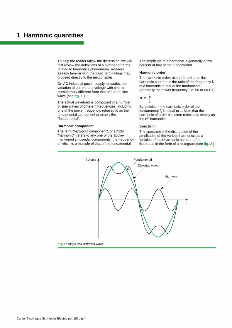
On AC industrial power supply networks, thevariation of current and voltage with time isconsiderably different from that of a pure sinewave (see fig. 1 ).
The actual waveform is composed of a numberof sine waves of different frequencies, includingone at the power frequency, referred to as thefundamental component or simply the"fundamental".
Harmonic componentThe term "harmonic component", or simply"harmonic", refers to any one of the above-mentioned sinusoidal components, the frequencyof which is a multiple of that of the fundamental.
Harmonic
t
Fundamental
Distorted wave
I phase
The amplitude of a harmonic is generally a fewpercent of that of the fundamental.
Harmonic orderThe harmonic order, also referred to as theharmonic number, is the ratio of the frequency fnof a harmonic to that of the fundamental(generally the power frequency, i.e. 50 or 60 Hz):
n = ffn
1
By definition, the harmonic order of thefundamental f1 is equal to 1. Note that theharmonic of order n is often referred to simply asthe nth harmonic.
Spectrum
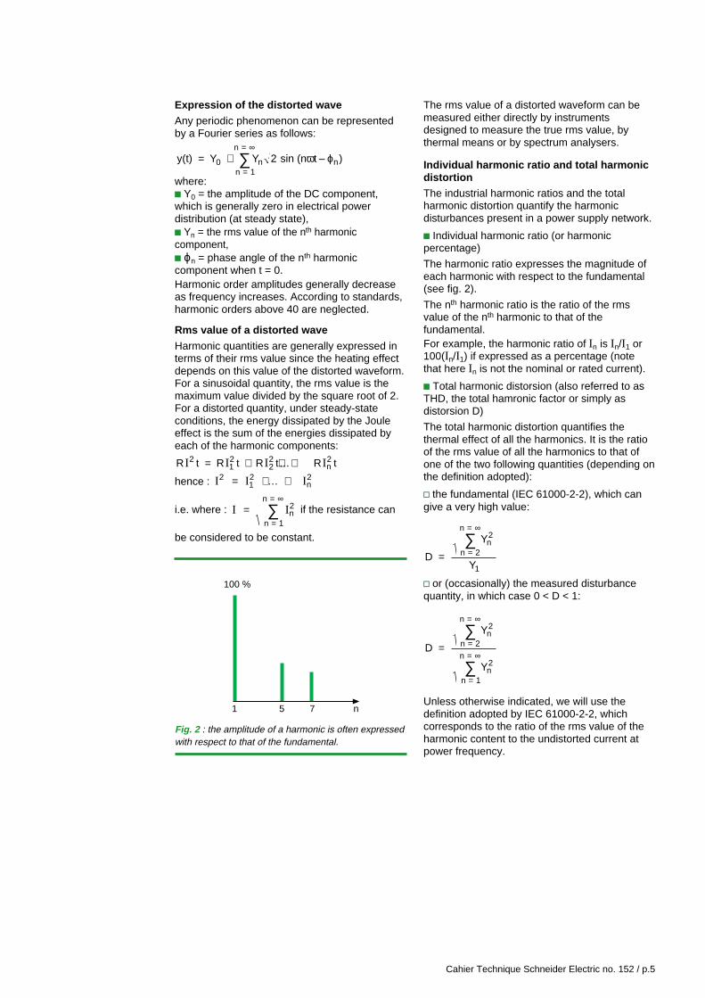
The spectrum is the distribution of theamplitudes of the various harmonics as afunction of their harmonic number, oftenillustrated in the form of a histogram (see fig. 2 ).
Fig.1 : shape of a distorted wave.
Cahier Technique Schneider Electric no. 152 / p.5
The rms value of a distorted waveform can bemeasured either directly by instrumentsdesigned to measure the true rms value, bythermal means or by spectrum analysers.
Individual harmonic ratio and total harmonicdistortionThe industrial harmonic ratios and the totalharmonic distortion quantify the harmonicdisturbances present in a power supply network.
c Individual harmonic ratio (or harmonicpercentage)
The harmonic ratio expresses the magnitude ofeach harmonic with respect to the fundamental(see fig. 2).
The nth harmonic ratio is the ratio of the rmsvalue of the nth harmonic to that of thefundamental.For example, the harmonic ratio of In is In/I1 or100(In/I1) if expressed as a percentage (notethat here In is not the nominal or rated current).
c Total harmonic distorsion (also referred to asTHD, the total hamronic factor or simply asdistorsion D)
The total harmonic distortion quantifies thethermal effect of all the harmonics. It is the ratioof the rms value of all the harmonics to that ofone of the two following quantities (depending onthe definition adopted):
v the fundamental (IEC 61000-2-2), which cangive a very high value:
D
Y
Y
n2
n = 2
n =
1=
∞
∑
v or (occasionally) the measured disturbancequantity, in which case 0 < D < 1:
D
Y
Y
n2
n = 2
n =
n2
n = 1
n = =
∞
∞
∑
∑
Unless otherwise indicated, we will use thedefinition adopted by IEC 61000-2-2, whichcorresponds to the ratio of the rms value of theharmonic content to the undistorted current atpower frequency.
Fig. 2 : the amplitude of a harmonic is often expressedwith respect to that of the fundamental.
100 %
1 5 7 n
Expression of the distorted waveAny periodic phenomenon can be representedby a Fourier series as follows:
y(t) Y Y sin (n t – )0 n nn = 1
n = = +
∞
∑ 2 ω ϕ
where:c Y0 = the amplitude of the DC component,which is generally zero in electrical powerdistribution (at steady state),c Yn = the rms value of the nth harmoniccomponent,c ϕn = phase angle of the nth harmoniccomponent when t = 0.Harmonic order amplitudes generally decreaseas frequency increases. According to standards,harmonic orders above 40 are neglected.
Rms value of a distorted wave
Harmonic quantities are generally expressed interms of their rms value since the heating effectdepends on this value of the distorted waveform.For a sinusoidal quantity, the rms value is themaximum value divided by the square root of 2.For a distorted quantity, under steady-stateconditions, the energy dissipated by the Jouleeffect is the sum of the energies dissipated byeach of the harmonic components:
R t R t R t R t212
22
n2I I I I= + +…+
hence : I I I2 12
n2= + … +
i.e. where : I I n2
n = 1
n = =
∞
∑ if the resistance can
be considered to be constant.
Cahier Technique Schneider Electric no. 152 / p.6
2 Principal disturbances caused byharmonic currents and voltages
Harmonic currents and voltages superimposedon the fundamental have combined effects onequipment and devices connected to the powersupply network.
The detrimental effects of these harmonics dependon the type of load encountered, and include:c instantaneous effects,c long-term effects due to heating.
2.1 Instantaneous effects
Harmonic voltages can disturb controllers usedin electronic systems. They can, for example,affect thyristor switching conditions by displacingthe zero-crossing of the voltage wave (seeIEC 146-2 and Schneider Electric "CahierTechnique" n° 141).
Harmonics can cause additional errors ininduction-disk electricity meters. For example,the error of a class 2 meter will be increased by0.3% by a 5th harmonic ratio of 5% in currentand voltage.
Ripple control receivers, such as the relays usedby electrical utilities for centralised remotecontrol, can be disturbed by voltage harmonicswith frequencies in the neighbourhood of thecontrol frequency. Other sources of disturbancesaffecting these relays, related to the harmonicimpedance of the network, will be discussedfurther on.
Vibrations and noise
The electrodynamic forces produced by theinstantaneous currents associated with harmoniccurrents cause vibrations and acoustical noise,especially in electromagnetic devices(transformers, reactors, etc.).Pulsating mechanical torque, due to harmonicrotating fields, can produce vibrations in rotatingmachines.
Interference on communication and controlcircuits (telephone, control and monitoring)
Disturbances are observed when communicationor control circuits are run along side powerdistribution circuits carrying distorted currents.Parameters that must be taken into accountinclude the length of parallel running, the distancebetween the two circuits and the harmonicfrequencies (coupling increases with frequency).
2.2 Long-term effects
Over and above mechanical fatigue due tovibrations, the main long-term effect ofharmonics is heating.
Capacitor heatingThe losses causing heating are due to twophenomena: conduction and dielectrichysteresis.As a first approximation, they are proportional tothe square of the rms current.
Capacitors are therefore sensitive to overloads,whether due to an excessively high fundamentalor to the presence of voltage harmonics.
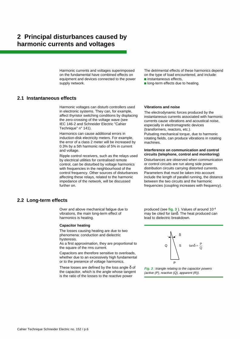
These losses are defined by the loss angle δ ofthe capacitor, which is the angle whose tangentis the ratio of the losses to the reactive power
Q
δ
P
S tanδ = PQ
Fig. 3 : triangle relating to the capacitor powers(active (P), reactive (Q), apparent (R)).
produced (see fig. 3 ). Values of around 10-4
may be cited for tanδ. The heat produced canlead to dielectric breakdown.
Cahier Technique Schneider Electric no. 152 / p.7
Heating due to additional losses in machinesand transformersc additional losses in the stators (copper andiron) and principally in the rotors (dampingwindings, magnetic circuits) of machines causedby the considerable differences in speed betweenthe harmonic inducing rotating fields and therotor. Note that rotor measurements (temperature,induced currents) are difficult if not impossible,
c supplementary losses in transformers due tothe skin effect (increase in the resistance ofcopper with frequency), hysteresis and eddycurrents (in the magnetic circuit).
Heating of cables and equipmentLosses are increased in cables carryingharmonic currents, resulting in temperature rise.The causes of the additional losses include:
c an increase in the rms value of the current foran equal active power consumed;
c an increase in the apparent resistance of thecore with frequency, due to the skin effect;
c an increase in dielectric losses in the insulationwith frequency, if the cable is subjected to non-negligible voltage distortion;
c phenomena related to the proximity ofconductors with respect to metal cladding and
shielding earthed at both ends of the cable, etc.Calculations for steady state can be carried outas described in IEC 60287.
Generally speaking, all electrical equipment(electrical switchboards) subjected to voltageharmonics or through which harmonic currentsflow, exhibit increased energy losses and shouldbe derated if necessary.
For example, a capacitor feeder cubicle shouldbe designed for a current equal to 1.3 times thereactive compensation current. This safety factordoes not however take into account theincreased heating due to the skin effect in theconductors.Harmonic distortion of currents and voltages ismeasured using spectrum analysers, providingthe amplitude of each component.It is important to use current or voltage sensorshaving a sufficient band width for the measuredfrequencies.
The rms value of the distorted current (orvoltage) may be assessed in any of three ways:
c measurement using a device designed to givethe true rms value,
c reconstitution on the basis of the spectrumprovided by spectral analysis,
c estimation from an oscilloscope display.
Cahier Technique Schneider Electric no. 152 / p.8
3 Acceptable limits, recommendations and standards
3.1 General limits
3.2 Standardised limits
c power capacitors: current distortion = 83%,corresponding to an overload of 30% (1.3 times therated current); overvoltages can reach up to 10%;
c sensitive electronics: 5% voltage distortion witha maximum individual harmonic percentage of3% depending on the equipment.
The series of standards (IEC 61000) forelectromagnetic compatibility define certain limitsconcerning harmonics, mainly:
c IEC 61000-3-2 which define the limits ofharmonic emissions for equipment consuming lessthan 16 A per phase (except for certain categoryof equipment indicated in the standards).The case of equipment consuming over 16 A perphase is examined in the technical spec. IEC/TS61000-3-4 and should finally be determined bythe projected standards IEC 61000-3-12.
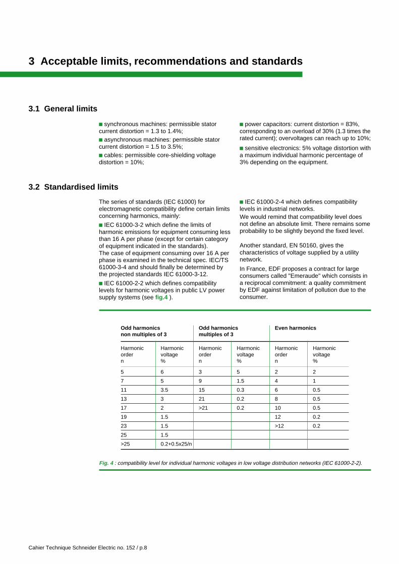
c IEC 61000-2-2 which defines compatibilitylevels for harmonic voltages in public LV powersupply systems (see fig.4 ).
c IEC 61000-2-4 which defines compatibilitylevels in industrial networks.We would remind that compatibility level doesnot define an absolute limit. There remains someprobability to be slightly beyond the fixed level.
Another standard, EN 50160, gives thecharacteristics of voltage supplied by a utilitynetwork.
In France, EDF proposes a contract for largeconsumers called "Emeraude" which consists ina reciprocal commitment: a quality commitmentby EDF against limitation of pollution due to theconsumer.
c synchronous machines: permissible statorcurrent distortion = 1.3 to 1.4%;c asynchronous machines: permissible statorcurrent distortion = 1.5 to 3.5%;c cables: permissible core-shielding voltagedistortion = 10%;
Fig. 4 : compatibility level for individual harmonic voltages in low voltage distribution networks (IEC 61000-2-2).
Odd harmonics Odd harmonics Even harmonicsnon multiples of 3 multiples of 3
Harmonic Harmonic Harmonic Harmonic Harmonic Harmonicorder voltage order voltage order voltagen % n % n %
5 6 3 5 2 2
7 5 9 1.5 4 1
11 3.5 15 0.3 6 0.5
13 3 21 0.2 8 0.5
17 2 >21 0.2 10 0.5
19 1.5 12 0.2
23 1.5 >12 0.2
25 1.5
>25 0.2+0.5x25/n
Cahier Technique Schneider Electric no. 152 / p.9
4 Harmonics generators
In industrial applications, the main types ofequipment that generate harmonics are:c static converters,c arc furnaces,
c lighting,c saturated reactors,c other equipment, such as rotating machineswhich generate slot harmonics (often negligible).
4.1 Static converters on 3-phase networks
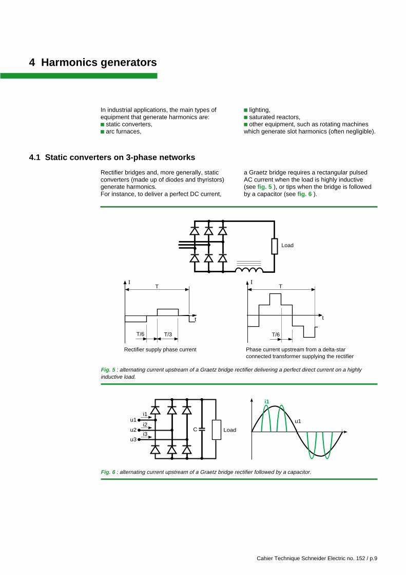
Rectifier bridges and, more generally, staticconverters (made up of diodes and thyristors)generate harmonics.For instance, to deliver a perfect DC current,
a Graetz bridge requires a rectangular pulsedAC current when the load is highly inductive(see fig. 5 ), or tips when the bridge is followedby a capacitor (see fig. 6 ).
Load
Phase current upstream from a delta-starconnected transformer supplying the rectifier
Rectifier supply phase current
T/6
IT
t
T/6 T/3
IT
t
u1
i1
C
i1u1
u2
u3
i2
i3Load
Fig. 5 : alternating current upstream of a Graetz bridge rectifier delivering a perfect direct current on a highlyinductive load.
Fig. 6 : alternating current upstream of a Graetz bridge rectifier followed by a capacitor.
Cahier Technique Schneider Electric no. 152 / p.10
In spite of their different waveforms, the currentsupstream and downstream from the delta-starconnected transformer have the samecharacteristic harmonic components.The characteristic harmonic components of thecurrent pulses supplying rectifiers have harmonicorders n, such as n = kp ± 1, where:c k = 1, 2, 3, 4, 5...c p = number of rectifier arms, for example:v Graetz bridge p = 6,v 6-pulse bridge p = 6,v 12-pulse bridge p = 12.
Applying the formula, the p = 6 rectifiers citedabove generate harmonics 5, 7, 11, 13, 17, 19,23, 25, etc., and the p = 12 rectifiers generateharmonics 11, 13, 23, 25, etc.
The characteristic harmonics are all odd-numbered and their currents, when nearing theideal case of figure 5, respect approximately theamplitude relation In = I1 /n where I1 is theamplitude of the fundamental.
This means that I5 and I7 will have the greatestamplitudes. Note that they can be eliminated byusing a 12-pulse bridge (p = 12).
In practice, the current spectrum is slightlydifferent. New even and odd harmonics, referredto as non-characteristic harmonics, of lowamplitudes, are created and the amplitudes ofthe characteristic harmonics are modified byseveral factors including:c asymmetry,c inaccuracy in thyristor firing times,c switching times,c imperfect filtering.
For thyristor bridges, a displacement of theharmonics as a function of the thyristor phaseangle may also be observed.Mixed thyristor-diode bridges generate evenharmonics. They are used only at low ratingsbecause the 2nd harmonic produces seriousdisturbances and is very difficult to eliminate.Other power converters such as cyclo-converters, dimmers, etc. have richer and morevariable spectra than rectifiers.
Note that they are sometimes replaced byrectifiers using the PWM (Pulse WidthModulation) technique. These devices operate athigh chopping frequencies (around 20 kHz) andare generally designed to generate only lowlevels of harmonics.
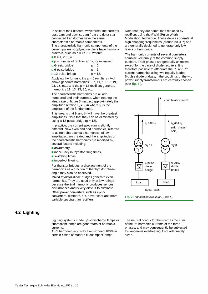
The harmonic currents of several converterscombine vectorially at the common supplybusbars. Their phases are generally unknownexcept for the case of diode rectifiers. It istherefore possible to attenuate the 5th and 7th
current harmonics using two equally loaded6-pulse diode bridges, if the couplings of the twopower supply transformers are carefully chosen(see fig. 7 ).
Load Load
I5 and I7 attenuated
Dy 11
6-pulsediodebridge
Yy 0
6-pulsediodebridge
Equal loads
I5 and I7
(with phase-shift)
I5 and I7
Fig. 7 : attenuation circuit for I5 and I7.
Lighting systems made up of discharge lamps orfluorescent lamps are generators of harmoniccurrents.A 3rd harmonic ratio may even exceed 100% incertain cases of modern fluocompact lamps.
4.2 Lighting
The neutral conductor then carries the sumof the 3rd harmonic currents of the threephases, and may consequently be subjectedto dangerous overheating if not adequatelysized.
Cahier Technique Schneider Electric no. 152 / p.11
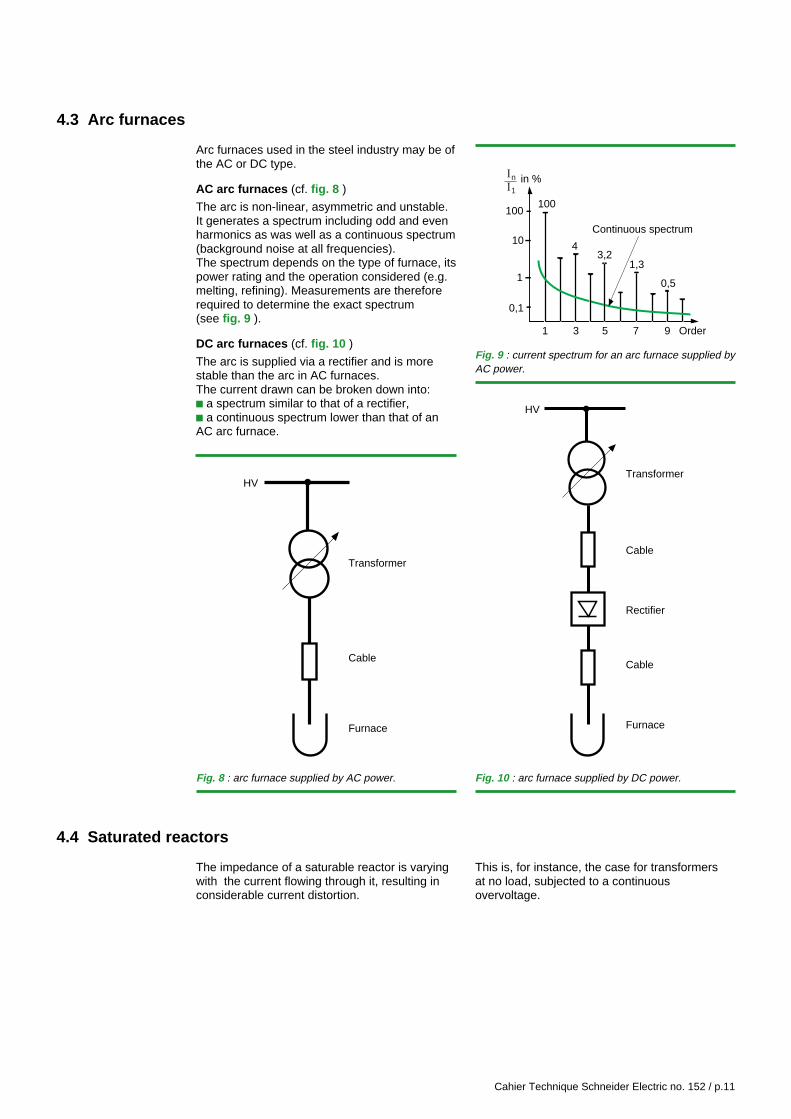
4.3 Arc furnaces
Arc furnaces used in the steel industry may be ofthe AC or DC type.
AC arc furnaces (cf. fig. 8 )
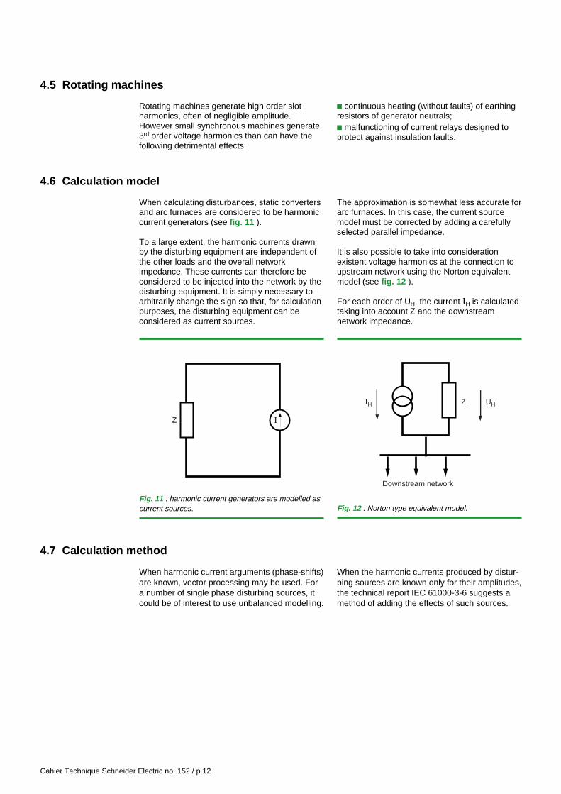
The arc is non-linear, asymmetric and unstable.It generates a spectrum including odd and evenharmonics as was well as a continuous spectrum(background noise at all frequencies).The spectrum depends on the type of furnace, itspower rating and the operation considered (e.g.melting, refining). Measurements are thereforerequired to determine the exact spectrum(see fig. 9 ).
DC arc furnaces (cf. fig. 10 )
The arc is supplied via a rectifier and is morestable than the arc in AC furnaces.The current drawn can be broken down into:c a spectrum similar to that of a rectifier,c a continuous spectrum lower than that of anAC arc furnace.
Furnace
Cable
Transformer
HV
1 3 5 7 9 Order
0,1
1
10
100
43,2
1,3
0,5
Continuous spectrum
in %
100
InI1
Furnace
Cable
Transformer
HV
Cable
Rectifier
Fig. 8 : arc furnace supplied by AC power. Fig. 10 : arc furnace supplied by DC power.
Fig. 9 : current spectrum for an arc furnace supplied byAC power.
4.4 Saturated reactors
The impedance of a saturable reactor is varyingwith the current flowing through it, resulting inconsiderable current distortion.
This is, for instance, the case for transformersat no load, subjected to a continuousovervoltage.
Cahier Technique Schneider Electric no. 152 / p.12
4.5 Rotating machines
Rotating machines generate high order slotharmonics, often of negligible amplitude.However small synchronous machines generate3rd order voltage harmonics than can have thefollowing detrimental effects:
c continuous heating (without faults) of earthingresistors of generator neutrals;c malfunctioning of current relays designed toprotect against insulation faults.
4.6 Calculation model
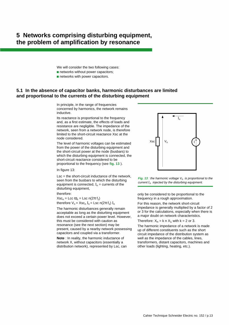
When calculating disturbances, static convertersand arc furnaces are considered to be harmoniccurrent generators (see fig. 11 ).
To a large extent, the harmonic currents drawnby the disturbing equipment are independent ofthe other loads and the overall networkimpedance. These currents can therefore beconsidered to be injected into the network by thedisturbing equipment. It is simply necessary toarbitrarily change the sign so that, for calculationpurposes, the disturbing equipment can beconsidered as current sources.
When harmonic current arguments (phase-shifts)are known, vector processing may be used. Fora number of single phase disturbing sources, itcould be of interest to use unbalanced modelling.
The approximation is somewhat less accurate forarc furnaces. In this case, the current sourcemodel must be corrected by adding a carefullyselected parallel impedance.
It is also possible to take into considerationexistent voltage harmonics at the connection toupstream network using the Norton equivalentmodel (see fig. 12 ).
For each order of UH, the current IH is calculatedtaking into account Z and the downstreamnetwork impedance.
IZ
Downstream network
ZIH UH
Fig. 11 : harmonic current generators are modelled ascurrent sources. Fig. 12 : Norton type equivalent model.
4.7 Calculation method
When the harmonic currents produced by distur-bing sources are known only for their amplitudes,the technical report IEC 61000-3-6 suggests amethod of adding the effects of such sources.
Cahier Technique Schneider Electric no. 152 / p.13
5 Networks comprising disturbing equipment,the problem of amplification by resonance
We will consider the two following cases:c networks without power capacitors;c networks with power capacitors.
5.1 In the absence of capacitor banks, harmonic disturbances are limitedand proportional to the currents of the disturbing equipment
In principle, in the range of frequenciesconcerned by harmonics, the network remainsinductive.
Its reactance is proportional to the frequencyand, as a first estimate, the effects of loads andresistance are negligible. The impedance of thenetwork, seen from a network node, is thereforelimited to the short-circuit reactance Xsc at thenode considered.
The level of harmonic voltages can be estimatedfrom the power of the disturbing equipment andthe short-circuit power at the node (busbars) towhich the disturbing equipment is connected, theshort-circuit reactance considered to beproportional to the frequency (see fig. 13 ).
In figure 13:
Lsc = the short-circuit inductance of the network,seen from the busbars to which the disturbingequipment is connected, In = currents of thedisturbing equipment,
therefore:Xscn = Lcc ωn = Lsc n(2π f1)therefore Vn = Xscn In = Lsc n(2π f1) In
The harmonic disturbances generally remainacceptable as long as the disturbing equipmentdoes not exceed a certain power level. However,this must be considered with caution asresonance (see the next section) may bepresent, caused by a nearby network possessingcapacitors and coupled via a transformer.
Note : In reality, the harmonic inductance ofnetwork X, without capacitors (essentially adistribution network), represented by Lsc, can
only be considered to be proportional to thefrequency in a rough approximation.
For this reason, the network short-circuitimpedance is generally multiplied by a factor of 2or 3 for the calculations, especially when there isa major doubt on network characteristics.
Therefore: Xn = k n X1 with k = 2 or 3.
The harmonic impedance of a network is madeup of different constituents such as the shortcircuit impedance of the distribution system aswell as the impedance of the cables, lines,transformers, distant capacitors, machines andother loads (lighting, heating, etc.).
In
VnXsc I
Fig. 13 : the harmonic voltage Vn is proportional to thecurrent In injected by the disturbing equipment.
Cahier Technique Schneider Electric no. 152 / p.14
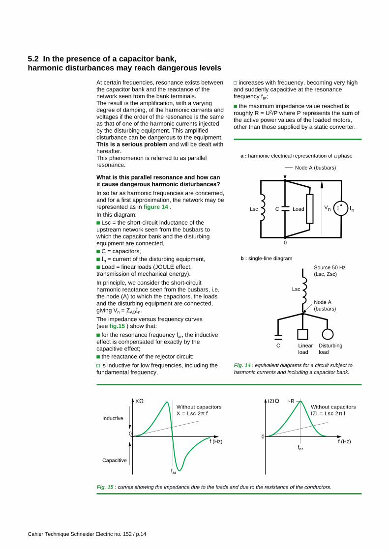
At certain frequencies, resonance exists betweenthe capacitor bank and the reactance of thenetwork seen from the bank terminals.The result is the amplification, with a varyingdegree of damping, of the harmonic currents andvoltages if the order of the resonance is the sameas that of one of the harmonic currents injectedby the disturbing equipment. This amplifieddisturbance can be dangerous to the equipment.This is a serious problem and will be dealt withhereafter.This phenomenon is referred to as parallelresonance.
What is this parallel resonance and how canit cause dangerous harmonic disturbances?
In so far as harmonic frequencies are concerned,and for a first approximation, the network may berepresented as in figure 14 .In this diagram:c Lsc = the short-circuit inductance of theupstream network seen from the busbars towhich the capacitor bank and the disturbingequipment are connected,c C = capacitors,c In = current of the disturbing equipment,c Load = linear loads (JOULE effect,transmission of mechanical energy).
In principle, we consider the short-circuitharmonic reactance seen from the busbars, i.e.the node (A) to which the capacitors, the loadsand the disturbing equipment are connected,giving Vn = ZAOIn.
The impedance versus frequency curves(see fig.15 ) show that:
c for the resonance frequency far, the inductiveeffect is compensated for exactly by thecapacitive effect;c the reactance of the rejector circuit:
v is inductive for low frequencies, including thefundamental frequency,
Node A (busbars)
Node A (busbars)
Lsc C
0
InVnLoad
Lsc
Source 50 Hz(Lsc, Zsc)
C Linearload
Disturbingload
a : harmonic electrical representation of a phase
b : single-line diagram
I
Fig. 14 : equivalent diagrams for a circuit subject toharmonic currents and including a capacitor bank.
Fig. 15 : curves showing the impedance due to the loads and due to the resistance of the conductors.
f (Hz)
Capacitive
0
far
Without capacitorsX = Lsc 2π f
XΩWithout capacitorsIZI = Lsc 2π f
f (Hz)far
0
IZIΩ ~R
Inductive
v increases with frequency, becoming very highand suddenly capacitive at the resonancefrequency far;
c the maximum impedance value reached isroughly R = U2/P where P represents the sum ofthe active power values of the loaded motors,other than those supplied by a static converter.
5.2 In the presence of a capacitor bank,harmonic disturbances may reach dangerous levels
Cahier Technique Schneider Electric no. 152 / p.15
If a harmonic current In of order n, with the samefrequency as the parallel resonance frequencyfar, is injected by the disturbing equipment, thecorresponding harmonic voltage can beestimated as Vn = R In with n = n ar = f ar/f1.
Estimation of n ar
The order nar of parallel resonance is the ratio ofthe resonance frequency far to the fundamentalfrequency f1 (power frequency).
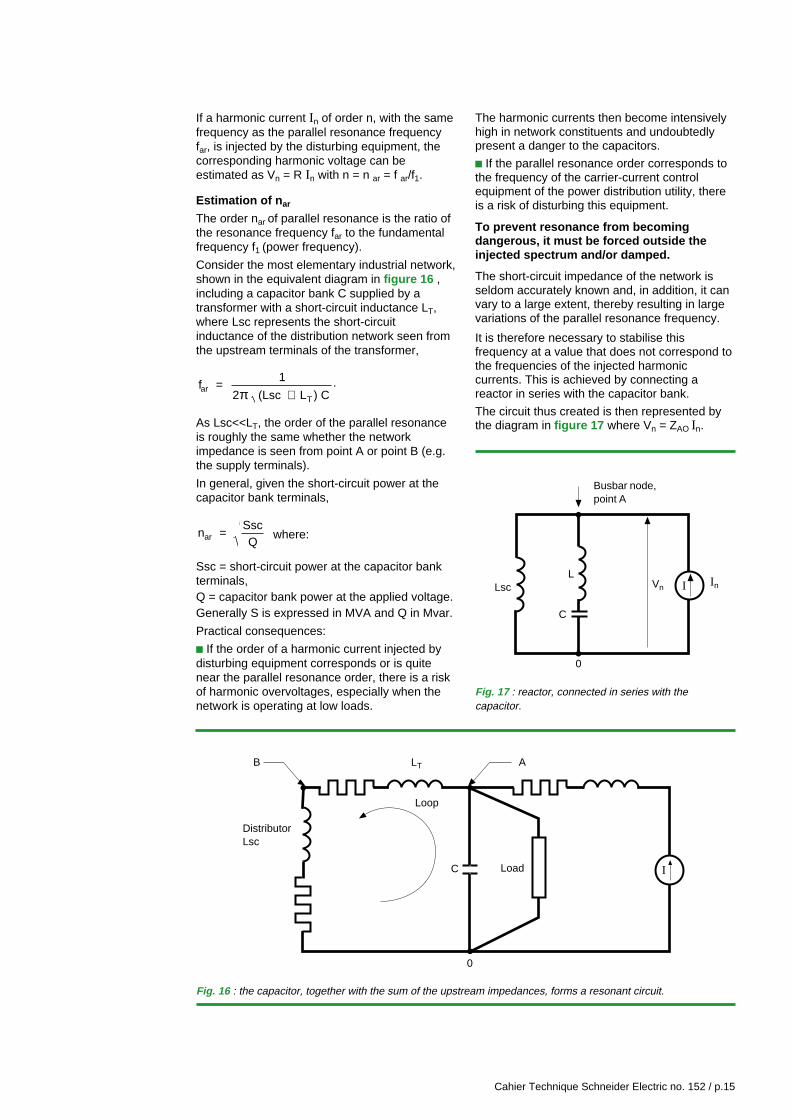
Consider the most elementary industrial network,shown in the equivalent diagram in figure 16 ,including a capacitor bank C supplied by atransformer with a short-circuit inductance LT,where Lsc represents the short-circuitinductance of the distribution network seen fromthe upstream terminals of the transformer,
f 1
2 (Lsc L ) Car
T
=+π
.
As Lsc<<LT, the order of the parallel resonanceis roughly the same whether the networkimpedance is seen from point A or point B (e.g.the supply terminals).
In general, given the short-circuit power at thecapacitor bank terminals,
n SscQar = where:
Ssc = short-circuit power at the capacitor bankterminals,Q = capacitor bank power at the applied voltage.Generally S is expressed in MVA and Q in Mvar.
Practical consequences:
c If the order of a harmonic current injected bydisturbing equipment corresponds or is quitenear the parallel resonance order, there is a riskof harmonic overvoltages, especially when thenetwork is operating at low loads.
The harmonic currents then become intensivelyhigh in network constituents and undoubtedlypresent a danger to the capacitors.
c If the parallel resonance order corresponds tothe frequency of the carrier-current controlequipment of the power distribution utility, thereis a risk of disturbing this equipment.
To prevent resonance from becomingdangerous, it must be forced outside theinjected spectrum and/or damped.
The short-circuit impedance of the network isseldom accurately known and, in addition, it canvary to a large extent, thereby resulting in largevariations of the parallel resonance frequency.
It is therefore necessary to stabilise thisfrequency at a value that does not correspond tothe frequencies of the injected harmoniccurrents. This is achieved by connecting areactor in series with the capacitor bank.
The circuit thus created is then represented bythe diagram in figure 17 where Vn = ZAO In.
Fig. 16 : the capacitor, together with the sum of the upstream impedances, forms a resonant circuit.
DistributorLsc
B ALT
Loop
LoadC
0
I
Busbar node,point A
Lsc
C
0
InVn
LI
Fig. 17 : reactor, connected in series with thecapacitor.
Cahier Technique Schneider Electric no. 152 / p.16
A series resonance, between L and C, appears.As opposed to this resonance, which gives aminimum impedance, the parallel resonance isoften referred to an anti-resonance.
The equation giving the frequency of the anti-
resonance is: f 1
2 (Lsc L) Car =
+π
Lsc generally being small compared to L, theequation shows that the presence of reactor L,connected in series with the capacitors, rendersthe frequency far less sensitive to the variationsof the short-circuit inductance Lsc (from theconnection points = busbars A).
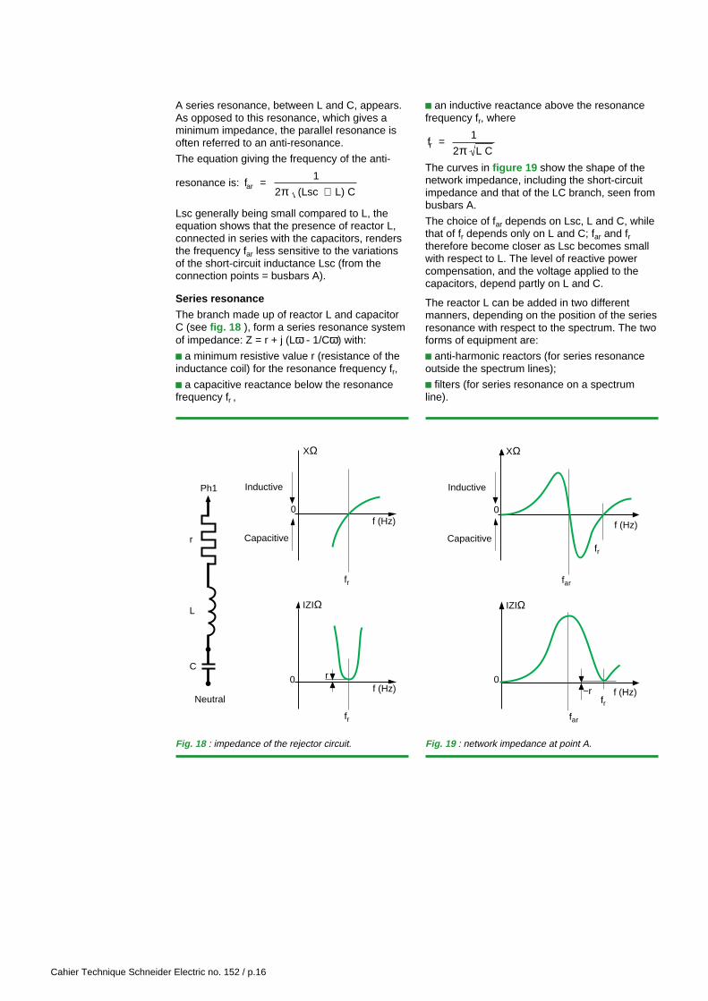
Series resonance
The branch made up of reactor L and capacitorC (see fig. 18 ), form a series resonance systemof impedance: Z = r + j (Lω - 1/Cω) with:
c a minimum resistive value r (resistance of theinductance coil) for the resonance frequency fr,
c a capacitive reactance below the resonancefrequency fr ,
0
XΩ
Inductive
Capacitive
IZIΩ
f (Hz)
f (Hz)0 r
Ph1
Neutral
fr
fr
C
L
r
f (Hz)
0
f (Hz)
XΩ
Inductive
Capacitivefr
far
far
fr
0
IZIΩ
~r
c an inductive reactance above the resonancefrequency fr, where
fr 1
2 L C=
πThe curves in figure 19 show the shape of thenetwork impedance, including the short-circuitimpedance and that of the LC branch, seen frombusbars A.
The choice of far depends on Lsc, L and C, whilethat of fr depends only on L and C; far and frtherefore become closer as Lsc becomes smallwith respect to L. The level of reactive powercompensation, and the voltage applied to thecapacitors, depend partly on L and C.
The reactor L can be added in two differentmanners, depending on the position of the seriesresonance with respect to the spectrum. The twoforms of equipment are:
c anti-harmonic reactors (for series resonanceoutside the spectrum lines);
c filters (for series resonance on a spectrumline).
Fig. 18 : impedance of the rejector circuit. Fig. 19 : network impedance at point A.
Cahier Technique Schneider Electric no. 152 / p.17
6 Anti-harmonic reactors
An anti-harmonic reactor can be used to protecta capacitor bank against harmonic overloads.Such solutions are often referred to as detunedcapacitor banks or detuned filters.
The reference diagram is once again figure 17.
In this assembly, the choice of L is such that theLC branch (where L is the reactor and C thereactive power compensation capacitors)behaves inductively for the harmonic frequencies,over the spectrum.
As a result, the resonance frequency fr of thisbranch will be below the spectrum of thedisturbing equipment.
The LC branch and the network (Lsc) are thenboth inductive over the spectrum and the harmoniccurrents injected by the disturbing equipment aredivided in a manner inversely proportional to theimpedance. Harmonic currents are thereforegreatly restricted in the LC branch, protecting thecapacitors, and the major part of the harmoniccurrents flow in the rest of the network,especially in the short-circuit impedance.
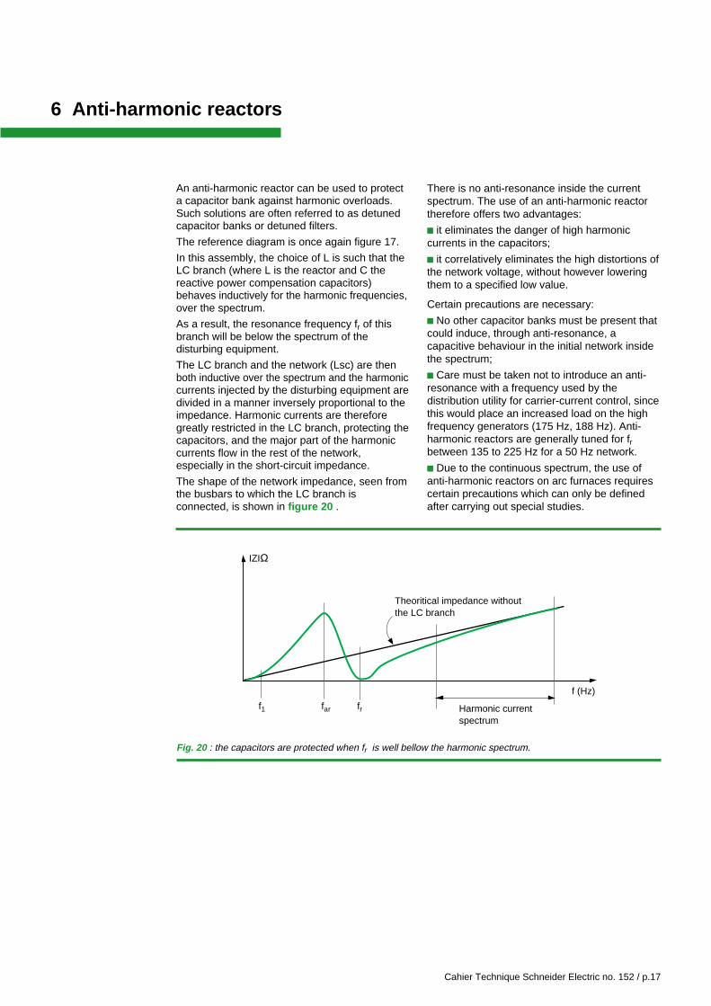
The shape of the network impedance, seen fromthe busbars to which the LC branch isconnected, is shown in figure 20 .
There is no anti-resonance inside the currentspectrum. The use of an anti-harmonic reactortherefore offers two advantages:
c it eliminates the danger of high harmoniccurrents in the capacitors;
c it correlatively eliminates the high distortions ofthe network voltage, without however loweringthem to a specified low value.
Certain precautions are necessary:
c No other capacitor banks must be present thatcould induce, through anti-resonance, acapacitive behaviour in the initial network insidethe spectrum;
c Care must be taken not to introduce an anti-resonance with a frequency used by thedistribution utility for carrier-current control, sincethis would place an increased load on the highfrequency generators (175 Hz, 188 Hz). Anti-harmonic reactors are generally tuned for frbetween 135 to 225 Hz for a 50 Hz network.
c Due to the continuous spectrum, the use ofanti-harmonic reactors on arc furnaces requirescertain precautions which can only be definedafter carrying out special studies.
IZIΩ
f1 fr
Theoritical impedance withoutthe LC branch
far
f (Hz)
Harmonic current spectrum
Fig. 20 : the capacitors are protected when fr is well bellow the harmonic spectrum.
Cahier Technique Schneider Electric no. 152 / p.18
7 Filters
Filters are used when it is necessary to limitharmonic voltages present on a network to aspecified low value.Three types of filters may be used to reduceharmonic voltages:
c resonant shunt filters,
c damped filters,
c active filters.
7.1 Resonant shunt filters
The resonant shunt filter (see fig. 18) is made upof an LC branch with a frequency of
fr 1
2 L C=
πtuned to the frequency of the voltage harmonic tobe eliminated.
This approach is therefore fundamentallydifferent than that of reactor-connectedcapacitors already described.
At fr, the resonant shunt presents a low minimumimpedance with respect to the resistance r of thereactor. It therefore absorbs nearly all theharmonic currents of frequency fr injected, withlow harmonic voltage distortion (sinceproportional to the product of the resistance rand the current flowing in the filter) at thisfrequency.
In principle, a resonant shunt is installed for eachharmonic to be limited. They are connected tothe busbars for which harmonic voltage reductionis specified. Together they form a filter bank.
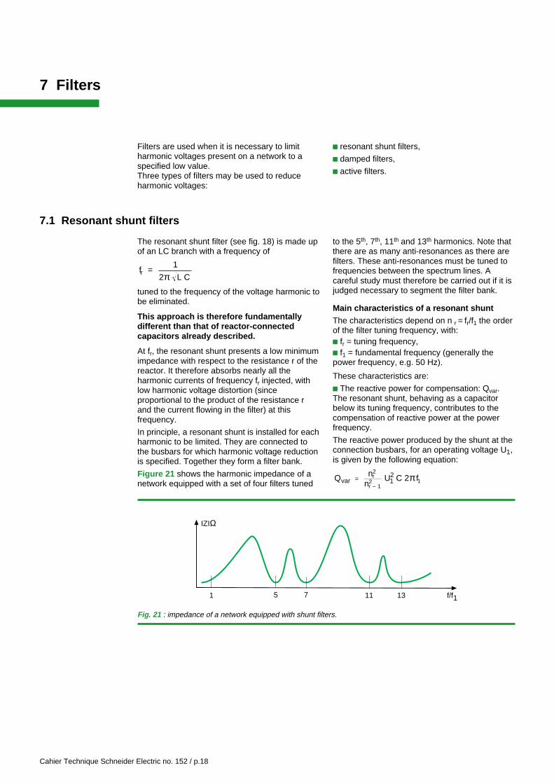
Figure 21 shows the harmonic impedance of anetwork equipped with a set of four filters tuned
to the 5th, 7th, 11th and 13th harmonics. Note thatthere are as many anti-resonances as there arefilters. These anti-resonances must be tuned tofrequencies between the spectrum lines. Acareful study must therefore be carried out if it isjudged necessary to segment the filter bank.
Main characteristics of a resonant shuntThe characteristics depend on n r = fr/f1 the orderof the filter tuning frequency, with:c fr = tuning frequency,c f1 = fundamental frequency (generally thepower frequency, e.g. 50 Hz).
These characteristics are:
c The reactive power for compensation: Qvar.The resonant shunt, behaving as a capacitorbelow its tuning frequency, contributes to thecompensation of reactive power at the powerfrequency.
The reactive power produced by the shunt at theconnection busbars, for an operating voltage U1,is given by the following equation:
Qvar 12
nn
U C 2 fr2
r – 12 1= π
1 5 7 11 13 f/f1
IZIΩ
Fig. 21 : impedance of a network equipped with shunt filters.
Cahier Technique Schneider Electric no. 152 / p.19
(note that the subscript 1 refers to thefundamental); C is the phase-to-neutralcapacitance of one of the 3 branches of the filterbank represented as a star.
At first glance, the presence of a reactor wouldnot be expected to increase the reactive powersupplied. The reason is the increase in voltage atpower frequency f1 caused by the inductance atthe capacitor terminals.
c Characteristic impedance X0 LC
=
c The quality factor q = X0/rAn effective filter must have a reactor with alarge quality factor q, therefore r << X0 atfrequency fr.Approximate values of q:v for air-cored reactors,v greater than 75 for iron-core reactors.
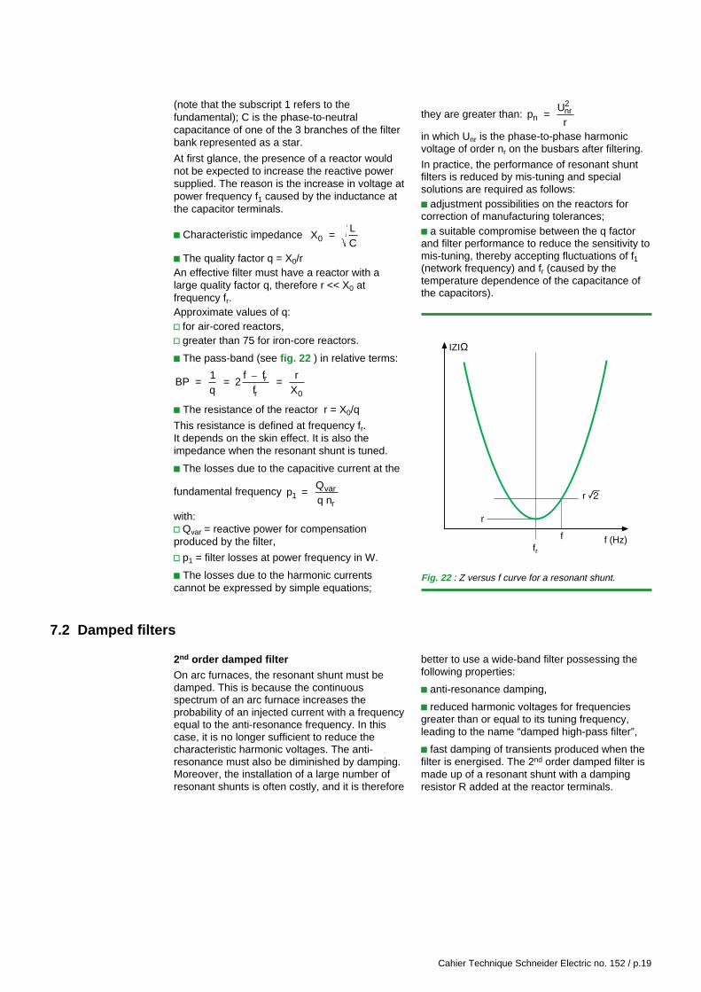
c The pass-band (see fig. 22 ) in relative terms:
BP 1q
2f f
f
rX
r
r 0= = =–
c The resistance of the reactor r = X0/q
This resistance is defined at frequency fr.It depends on the skin effect. It is also theimpedance when the resonant shunt is tuned.
c The losses due to the capacitive current at the
fundamental frequency p1 Qq n
var
r=
with:v Qvar = reactive power for compensationproduced by the filter,
v p1 = filter losses at power frequency in W.
c The losses due to the harmonic currentscannot be expressed by simple equations;
they are greater than: pn U
rnr2
=
in which Unr is the phase-to-phase harmonicvoltage of order nr on the busbars after filtering.
In practice, the performance of resonant shuntfilters is reduced by mis-tuning and specialsolutions are required as follows:c adjustment possibilities on the reactors forcorrection of manufacturing tolerances;c a suitable compromise between the q factorand filter performance to reduce the sensitivity tomis-tuning, thereby accepting fluctuations of f1(network frequency) and fr (caused by thetemperature dependence of the capacitance ofthe capacitors).
r
r r
ffr
f (Hz)
IZIΩ
Fig. 22 : Z versus f curve for a resonant shunt.
7.2 Damped filters
2nd order damped filterOn arc furnaces, the resonant shunt must bedamped. This is because the continuousspectrum of an arc furnace increases theprobability of an injected current with a frequencyequal to the anti-resonance frequency. In thiscase, it is no longer sufficient to reduce thecharacteristic harmonic voltages. The anti-resonance must also be diminished by damping.Moreover, the installation of a large number ofresonant shunts is often costly, and it is therefore
better to use a wide-band filter possessing thefollowing properties:
c anti-resonance damping,
c reduced harmonic voltages for frequenciesgreater than or equal to its tuning frequency,leading to the name “damped high-pass filter”,
c fast damping of transients produced when thefilter is energised. The 2nd order damped filter ismade up of a resonant shunt with a dampingresistor R added at the reactor terminals.
Cahier Technique Schneider Electric no. 152 / p.20
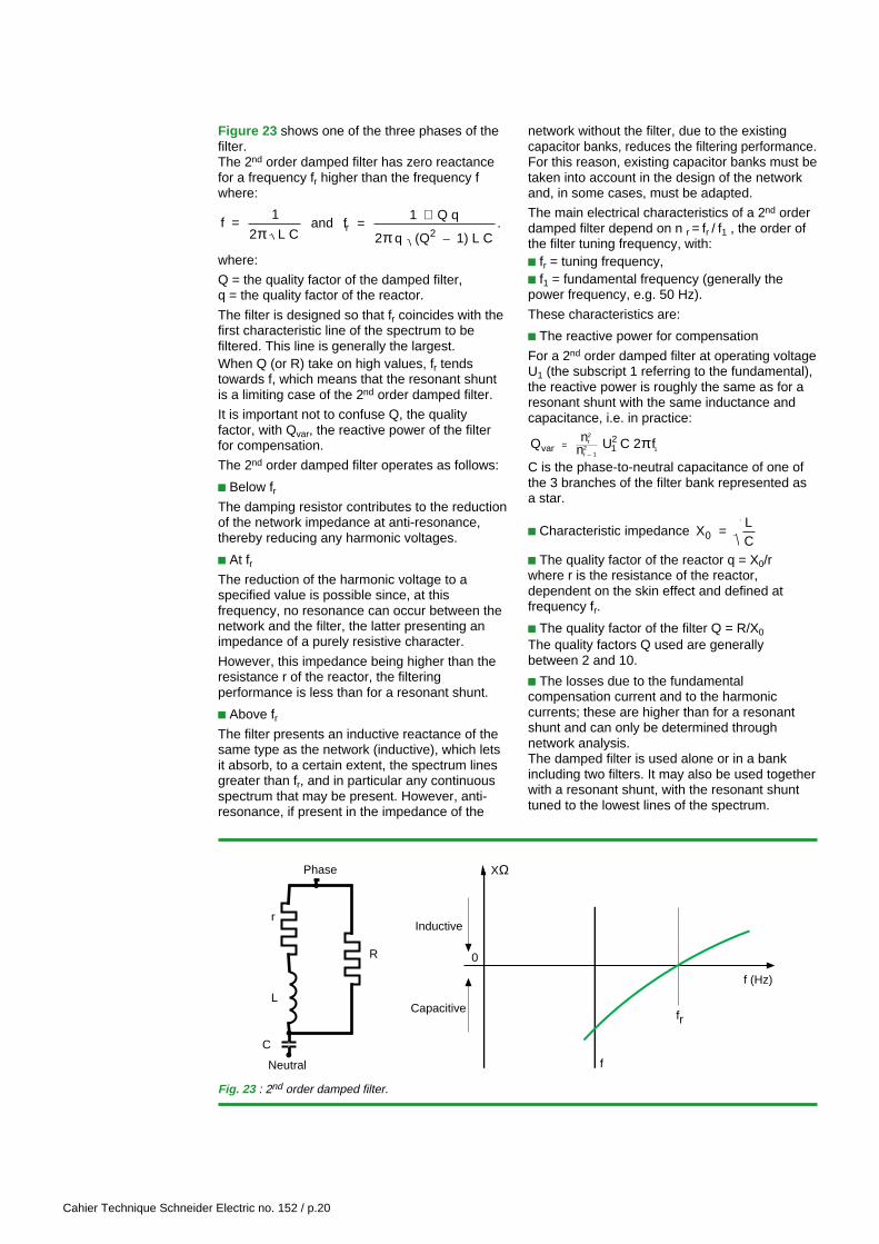
Figure 23 shows one of the three phases of thefilter.The 2nd order damped filter has zero reactancefor a frequency fr higher than the frequency fwhere:
f 1
2 L C=
π and fr
1 Q q
2 q (Q 1) L C 2= +
π –.
where:
Q = the quality factor of the damped filter,q = the quality factor of the reactor.
The filter is designed so that fr coincides with thefirst characteristic line of the spectrum to befiltered. This line is generally the largest.When Q (or R) take on high values, fr tendstowards f, which means that the resonant shuntis a limiting case of the 2nd order damped filter.
It is important not to confuse Q, the qualityfactor, with Qvar, the reactive power of the filterfor compensation.
The 2nd order damped filter operates as follows:
c Below frThe damping resistor contributes to the reductionof the network impedance at anti-resonance,thereby reducing any harmonic voltages.
c At frThe reduction of the harmonic voltage to aspecified value is possible since, at thisfrequency, no resonance can occur between thenetwork and the filter, the latter presenting animpedance of a purely resistive character.
However, this impedance being higher than theresistance r of the reactor, the filteringperformance is less than for a resonant shunt.
c Above frThe filter presents an inductive reactance of thesame type as the network (inductive), which letsit absorb, to a certain extent, the spectrum linesgreater than fr, and in particular any continuousspectrum that may be present. However, anti-resonance, if present in the impedance of the
network without the filter, due to the existingcapacitor banks, reduces the filtering performance.For this reason, existing capacitor banks must betaken into account in the design of the networkand, in some cases, must be adapted.
The main electrical characteristics of a 2nd orderdamped filter depend on n r = fr / f1 , the order ofthe filter tuning frequency, with:c fr = tuning frequency,c f1 = fundamental frequency (generally thepower frequency, e.g. 50 Hz).
These characteristics are:
c The reactive power for compensation
For a 2nd order damped filter at operating voltageU1 (the subscript 1 referring to the fundamental),the reactive power is roughly the same as for aresonant shunt with the same inductance andcapacitance, i.e. in practice:
Q nn U C 2 fvar 1
2 r
2
r – 12 1= π
C is the phase-to-neutral capacitance of one ofthe 3 branches of the filter bank represented asa star.
c Characteristic impedance X0 LC
=
c The quality factor of the reactor q = X0/rwhere r is the resistance of the reactor,dependent on the skin effect and defined atfrequency fr.
c The quality factor of the filter Q = R/X0
The quality factors Q used are generallybetween 2 and 10.
c The losses due to the fundamentalcompensation current and to the harmoniccurrents; these are higher than for a resonantshunt and can only be determined throughnetwork analysis.The damped filter is used alone or in a bankincluding two filters. It may also be used togetherwith a resonant shunt, with the resonant shunttuned to the lowest lines of the spectrum.
0
f (Hz)
fr
f
XΩ
Inductive
Capacitive
Neutral
r
C
L
Phase
R
Fig. 23 : 2nd order damped filter.
Cahier Technique Schneider Electric no. 152 / p.21
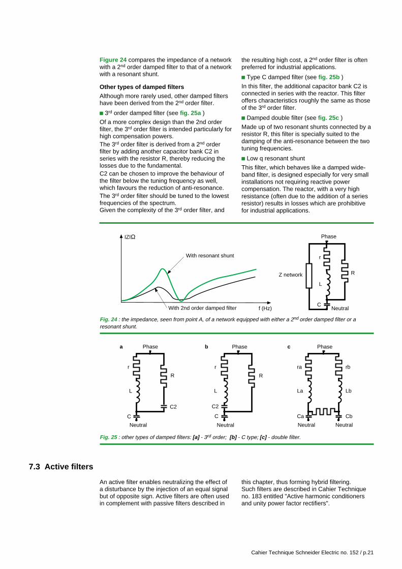
Figure 24 compares the impedance of a networkwith a 2nd order damped filter to that of a networkwith a resonant shunt.
Other types of damped filtersAlthough more rarely used, other damped filtershave been derived from the 2nd order filter.
c 3rd order damped filter (see fig. 25a )
Of a more complex design than the 2nd orderfilter, the 3rd order filter is intended particularly forhigh compensation powers.The 3rd order filter is derived from a 2nd orderfilter by adding another capacitor bank C2 inseries with the resistor R, thereby reducing thelosses due to the fundamental.C2 can be chosen to improve the behaviour ofthe filter below the tuning frequency as well,which favours the reduction of anti-resonance.The 3rd order filter should be tuned to the lowestfrequencies of the spectrum.Given the complexity of the 3rd order filter, and
Z network
f (Hz)
With resonant shunt
With 2nd order damped filter
IZIΩ
r
CNeutral
L
Phase
R
R
r
C
Neutral
L
Phase
C2
R
r
C
Neutral
L
Phase
C2
ra
La
rb
Lb
Ca
Neutral
Cb
Neutral
Phasea b c
the resulting high cost, a 2nd order filter is oftenpreferred for industrial applications.
c Type C damped filter (see fig. 25b )
In this filter, the additional capacitor bank C2 isconnected in series with the reactor. This filteroffers characteristics roughly the same as thoseof the 3rd order filter.
c Damped double filter (see fig. 25c )
Made up of two resonant shunts connected by aresistor R, this filter is specially suited to thedamping of the anti-resonance between the twotuning frequencies.
c Low q resonant shunt
This filter, which behaves like a damped wide-band filter, is designed especially for very smallinstallations not requiring reactive powercompensation. The reactor, with a very highresistance (often due to the addition of a seriesresistor) results in losses which are prohibitivefor industrial applications.
Fig. 24 : the impedance, seen from point A, of a network equipped with either a 2nd order damped filter or aresonant shunt.
Fig. 25 : other types of damped filters: [a] - 3rd order; [b] - C type; [c] - double filter.
7.3 Active filters
An active filter enables neutralizing the effect ofa disturbance by the injection of an equal signalbut of opposite sign. Active filters are often usedin complement with passive filters described in
this chapter, thus forming hybrid filtering.Such filters are described in Cahier Techniqueno. 183 entitled "Active harmonic conditionersand unity power factor rectifiers".
Cahier Technique Schneider Electric no. 152 / p.22
8 Example of the analysis of a simplified network
The diagram in figure 26 represents a simplifiednetwork comprising a 2,000 kVA six-pulse rectifier,injecting a harmonic current spectrum, and thefollowing equipment which will be consideredconsecutively in three different calculations:c a single 1,000 kvar capacitor bank;c anti-harmonic reactor-connected capacitorequipment rated 1,000 kvar;c a set of two filters comprising a resonant shunttuned to the 5th harmonic and a 2nd orderdamped filter tuned to the 7th harmonic.
Note that:c the 1,000 kvar compensation power is requiredto bring the power factor to a conventional value;c the harmonic voltages already present on the20 kV distribution network have been neglectedfor the sake of simplicity.
This example will be used to compare theperformance of the three solutions, however theresults can obviously not be applied directly toother cases.
Fig. 26 : installation with disturbing equipment, capacitors and filters.
Motor
Network20 kVIsc 12.5 kA
20/5.5 kV5,000 kVAUsc 7.5 %Pcu 40 kW
5,5/0.4 kV1,000 kVAUsc 5 %Pcu 12 kW
560 kW
500 kVA at cosϕ = 0.9
2,000 kVADisturbing equipment
Capa.
Reactor+capa.
Resonant shuntand2nd order damped filter
Load
8.1 Capacitor bank alone
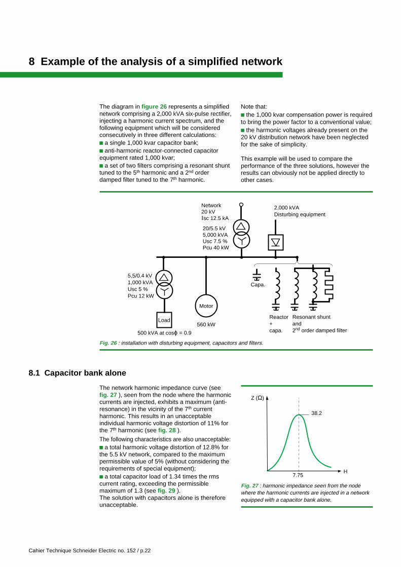
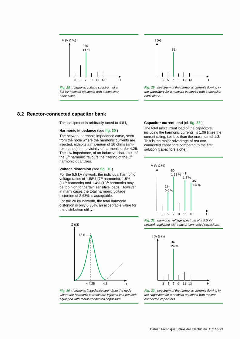
The network harmonic impedance curve (seefig. 27 ), seen from the node where the harmoniccurrents are injected, exhibits a maximum (anti-resonance) in the vicinity of the 7th currentharmonic. This results in an unacceptableindividual harmonic voltage distortion of 11% forthe 7th harmonic (see fig. 28 ).
The following characteristics are also unacceptable:c a total harmonic voltage distortion of 12.8% forthe 5.5 kV network, compared to the maximumpermissible value of 5% (without considering therequirements of special equipment);c a total capacitor load of 1.34 times the rmscurrent rating, exceeding the permissiblemaximum of 1.3 (see fig. 29 ).The solution with capacitors alone is thereforeunacceptable.
Fig. 27 : harmonic impedance seen from the nodewhere the harmonic currents are injected in a networkequipped with a capacitor bank alone.
H7.75
38.2
Z (Ω)
Cahier Technique Schneider Electric no. 152 / p.23
8.2 Reactor-connected capacitor bank
Fig. 28 : harmonic voltage spectrum of a5.5 kV network equipped with a capacitorbank alone.
Fig. 29 : spectrum of the harmonic currents flowing inthe capacitors for a network equipped with a capacitorbank alone.
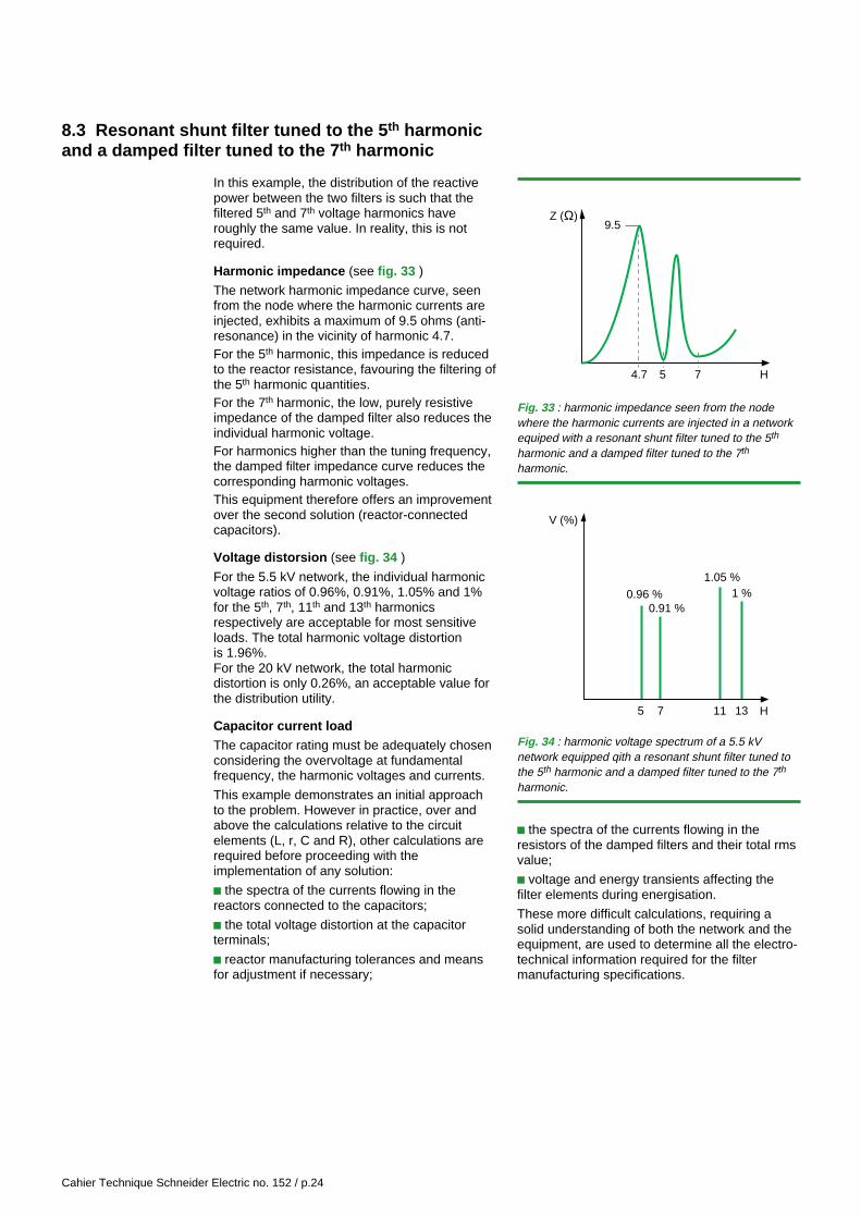
This equipment is arbitrarily tuned to 4.8 f1.
Harmonic impedance (see fig. 30 )
The network harmonic impedance curve, seenfrom the node where the harmonic currents areinjected, exhibits a maximum of 16 ohms (anti-resonance) in the vicinity of harmonic order 4.25.The low impedance, of an inductive character, ofthe 5th harmonic favours the filtering of the 5th
harmonic quantities.
Voltage distorsion (see fig. 31 )
For the 5.5 kV network, the individual harmonicvoltage ratios of 1.58% (7th harmonic), 1.5%(11th harmonic) and 1.4% (13th harmonic) maybe too high for certain sensitive loads. Howeverin many cases the total harmonic voltagedistortion of 2.63% is acceptable.
For the 20 kV network, the total harmonicdistortion is only 0.35%, an acceptable value forthe distribution utility.
Z (Ω)
H~ 4.25
15.6
4.8
Capacitor current load (cf. fig. 32 )
The total rms current load of the capacitors,including the harmonic currents, is 1.06 times thecurrent rating, i.e. less than the maximum of 1.3.This is the major advantage of rea ctor-connected capacitors compared to the firstsolution (capacitors alone).
Fig. 30 : harmonic impedance seen from the nodewhere the harmonic currents are injected in a networkequipped with reator-connected capacitors.
Fig. 32 : spectrum of the harmonic currents flowing inthe capacitors for a network equipped with reactor-connected capacitors.
Fig. 31 : harmonic voltage spectrum of a 5.5 kVnetwork equipped with reactor-connected capacitors.
3 5 7 9 H11 13
350 11 %
V (V & %)
3 5 7 9 H11 13
82
I (A)
3 5 7 9 H11 13
50 1.58 %
V (V & %)
19 0.6 %
48 1.5 %
451.4 %
5 7 H11 13
3424 %
I (A & %)
93
Cahier Technique Schneider Electric no. 152 / p.24
8.3 Resonant shunt filter tuned to the 5 th harmonicand a damped filter tuned to the 7 th harmonic
In this example, the distribution of the reactivepower between the two filters is such that thefiltered 5th and 7th voltage harmonics haveroughly the same value. In reality, this is notrequired.
Harmonic impedance (see fig. 33 )
The network harmonic impedance curve, seenfrom the node where the harmonic currents areinjected, exhibits a maximum of 9.5 ohms (anti-resonance) in the vicinity of harmonic 4.7.For the 5th harmonic, this impedance is reducedto the reactor resistance, favouring the filtering ofthe 5th harmonic quantities.For the 7th harmonic, the low, purely resistiveimpedance of the damped filter also reduces theindividual harmonic voltage.For harmonics higher than the tuning frequency,the damped filter impedance curve reduces thecorresponding harmonic voltages.This equipment therefore offers an improvementover the second solution (reactor-connectedcapacitors).
Voltage distorsion (see fig. 34 )
For the 5.5 kV network, the individual harmonicvoltage ratios of 0.96%, 0.91%, 1.05% and 1%for the 5th, 7th, 11th and 13th harmonicsrespectively are acceptable for most sensitiveloads. The total harmonic voltage distortionis 1.96%.For the 20 kV network, the total harmonicdistortion is only 0.26%, an acceptable value forthe distribution utility.
Capacitor current loadThe capacitor rating must be adequately chosenconsidering the overvoltage at fundamentalfrequency, the harmonic voltages and currents.
This example demonstrates an initial approachto the problem. However in practice, over andabove the calculations relative to the circuitelements (L, r, C and R), other calculations arerequired before proceeding with theimplementation of any solution:
c the spectra of the currents flowing in thereactors connected to the capacitors;
c the total voltage distortion at the capacitorterminals;
c reactor manufacturing tolerances and meansfor adjustment if necessary;
Z (Ω)
H4.7
9.5
75
5 7 H11 13
0.91 %
V (%)
0.96 %
1.05 %1 %
Fig. 34 : harmonic voltage spectrum of a 5.5 kVnetwork equipped qith a resonant shunt filter tuned tothe 5th harmonic and a damped filter tuned to the 7th
harmonic.
Fig. 33 : harmonic impedance seen from the nodewhere the harmonic currents are injected in a networkequiped with a resonant shunt filter tuned to the 5th
harmonic and a damped filter tuned to the 7th
harmonic.
c the spectra of the currents flowing in theresistors of the damped filters and their total rmsvalue;
c voltage and energy transients affecting thefilter elements during energisation.
These more difficult calculations, requiring asolid understanding of both the network and theequipment, are used to determine all the electro-technical information required for the filtermanufacturing specifications.
Cahier Technique Schneider Electric no. 152 / p.25
9 Conclusion
Static power converters are increasingly used inindustrial distribution. The same is true for arcfurnaces in the growing electric-powered steelindustry. All these loads produce harmonicdisturbances and generally require compensationof the reactive power they consume, leading tothe installation of capacitor banks.
If such capacitors are installed withoutprecaution, they can cause resonance with thenetwork reactors and amplify harmonicdisturbances.
Installers and operators of industrial networksare thus often confronted with a complexelectrical problem.
The main types of harmonic disturbances andthe technical means available to limit their extenthave been presented in this document. Withoutoffering an exhaustive study of the phenomenainvolved or relating all acquired experience, thisdocument should provide the necessarybackground to, if not solve the problems, at leastfacilitate discussions with specialists.
Schneider Electric has since 1970, a team ofspecialists to solve electrotechnical problems inelectrical networks, at the Corporate Researchand Development department, as well as asubsidiary specialized in implementing filters(Rectiphase).
Cahier Technique Schneider Electric no. 152 / p.26
Bibliography
Standards & recommendationsc IEC 60146: Semi-conductor converters.
c IEC 60287: Calculation of the continuouscurrent rating of cables.
c IEC 60871: Shunt capacitors for AC powersystems having a rated voltage above 660 V.
c IEC 61000-2-2: Compatibility levels for low-frequency conducted disturbances and signallingin public low-voltage power supply systems.
c IEC 61000-2-4: Compatibility levels inindustrial plants for low-frequency conducteddisturbances.
c IEC 61000-3-2: Limits for harmonic currentemissions for equipment with input current notexceeding 16 A per phase.
c IEC 61000-3-4: Limitation of emission ofharmonic currents in low-voltage power supplysystems for equipment with rated current greaterthan 16 A.
c IEC 61642: Industrial a.c. networks affected byharmonics - Application of filters and shuntcapacitors.
c IEEE 519: Recommended practices andrequirements for harmonic control in electricalpower systems - 1992.
Schneider Electric Cahiers Techniquesc Electrical disturbances in LV.R. CALVAS, Cahier Technique no. 141
c Active harmonic conditioners and unity powerfactor rectifiers.E. BETTEGA, J.N. FIORINA,Cahier Technique no. 183
Other publications
c Direct current transmission, volume 1.E. W. KIMBARK.published by: J. WILEY and SONS.
c Perturbations des réseaux industriels et dedistribution. Compensation par procédésstatiques.Résonances en présence des harmoniquescréés par le convertisseurs de puissance et lesfours à arc associés à des dispositifs decompensation.(Disturbances on industrial and distributionnetworks. Compensation by statisticalprocesses.Resonance in the presence of harmonicscreated by power converters and arc furnacesassociated with compensation equipment.)Michel LEMOINE DER EDF.RGE T 87 no. 12, 12/78.
c Pollution de la tension(Voltage disturbances).P. MEYNAUD - SER-DER EDF.RGE T 89 n° 9 09/80.
c Harmonics, characteristic parameters,methods of study, estimates of existing values inthe network.(ELECTRA) CIGRE 07/81.
c Courants harmoniques dans les redresseurstriphasés à commutation forcée.(Harmonic currents in forced commutation3-phase rectifiers)W. WARBOWSKI - CIRED 81.
c Origine et nature des perturbations dans lesréseaux industriels et de distribution.(Origin and nature of disturbances in industrialand distribution networks).Guy BONNARD - SER-DER-EDFRGE 1/82.
c Electrical power systems qualityDUGAN, McGRANAGAN, BEATYMcGraw-Hill, 1996.
c Line harmonics of converters with DC motorloads.A. DAVID GRAHAM andEMIL T. SCHONHOLZER.IEEE transactions on industry applications.Volume IA 19 no. 1 02/83.
Cahier Technique Schneider Electric no. 152 / p.27
c Filtrage d'harmoniques et compensation depuissance réactive - Optimisation desinstallations de compensation en présenced'harmoniques.(Harmonic filtering and reactive powercompensation - Optimising compensationinstallations in the presence of harmonics).P. SGARZI and S. THEOLERE,SEE Seminar RGE no. 6 06/88.
c Les harmoniques et les installationsélectriquesA. KOUYOUMDJIANSCHNEIDER ELECTRIC, 05/98(réf. MD1HRM1F).


Schneider Electric Direction Scientifique et Technique,Service Communication TechniqueF-38050 Grenoble cedex 9Fax: (33) 04 76 57 98 60
DTP: AXESS - Saint-Péray (07)Edition: Schneider ElectricPrinting: Imprimerie du Pont de Claix - Claix - France - 1500- 100 FF - ©
200
0 S
chne
ider
Ele
ctric
01-0063576