ca title 24 part 6 2013 building energy efficiency ... title 24 part 6 2013 building energy...
TRANSCRIPT
CA Title 24 Part 6 2013Building Energy Efficiency Standards
15 Day Language Overview15 Day Language Overview
Ryan SmillieRyan SmillieWattStopper District Manager –
Northern [email protected]

WattStopper is a Registered Provider with The American Institute of Architects Continuing Education Systems. Credit earned on completion of this program will be reported to CES Records for AIA members. Certificates of Completion for non-AIA members are available on request.
This program is registered with the AIA/CES for continuing professional education. As such, it does not include content that may be deemed or construed to be an approval or endorsement by the AIA of any material of construction or any method or manner of
i i i i i i i i Q ihandling, using, distributing, or dealing in any material or product. Questions related to specific materials, methods, and services will be addressed at the conclusion of this presentation.
Th k Y !Thank You!
Learning Objectivesg j
1. Review the methodology and sections used by the Title 24 standardTitle 24 standard
2. Identify requirements the CEC has for Lighting Control Devices (§110.9)
3. Review the Mandatory Lighting Control requirements (§130.0-130.5)
4 P id i f h i th I t i4. Provide an overview of changes in the Interior Lighting Power requirements (§140.6)
5 Provide an overview of changes in the Exterior5. Provide an overview of changes in the Exterior Lighting Power requirements (§140.7)
6. Review Residential Lighting Requirements (§150.0)
3
g g (§ )
T24 Handout & Additional Resources&
Click “here” for pdf copy
Useful info can also be found at:
p py
http://www.wattstopper.com
or
http://home.pacbell.net/knuffkep p
Note: This presentation is © by Watt Stopper & Charles Knuffke 2009. Others may use for non-
4
ycommercial purposes as long as copied material is properly attributed to the authors.
Slide FormatsS
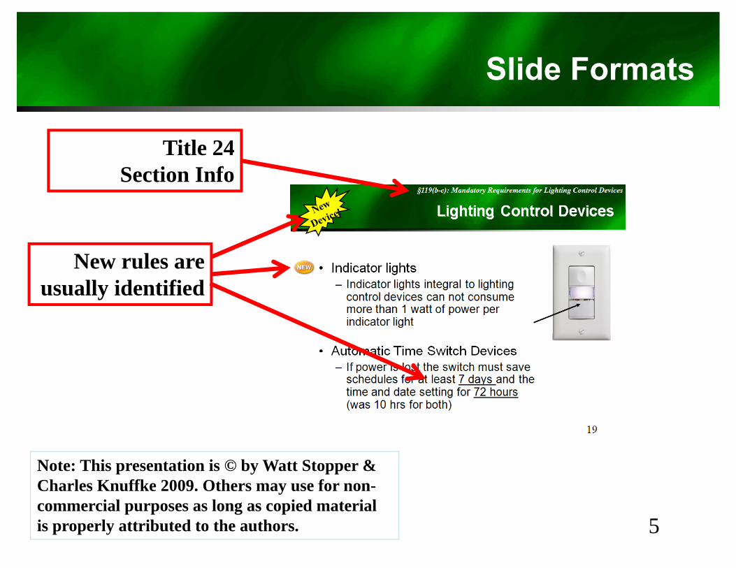
Title 24Title 24 Section Info
New rules are ll id tifi dusually identified
Note: This presentation is © by Watt Stopper & Charles Knuffke 2009 Others may use for non-
5
Charles Knuffke 2009. Others may use for noncommercial purposes as long as copied material is properly attributed to the authors.

Before we begin…g
The MessengerThe MessengerRequestsRequests
Th t H PlThat He PleaseNot Be Shot
6
Why Bother?y
• Energy SavingsGreen House Gas reductions– Green House Gas reductions
• Future Energy Supply QuestionsUncertain supply– Uncertain supply
– Capacity constraints• Cost and Environmental impact to build new
power new generation plants
• Zeitgeist, i.e. “Spirit of Times”G B ildi D i– Green Building Designs
– LEED– Darksky
7
Darksky
California Policy Goalsy
• “Zero Net Energy” levels by 2020 for residences• Zero Net Energy levels by 2020 for residences and by 2030 for nonresidential buildings– 2010 Lighting Action Plan (60-80%)– 2008 CPUC/CEC Energy Action Plan– 2008 CARB Climate Change Scoping Plan– 2008 CPUC California Long Term Energy Efficiency Strategic2008 CPUC California Long Term Energy Efficiency Strategic
Plan– 2007 CEC Integrated Energy Policy Report (IEPR)
2006 AB 32 Gl b l W i S l ti A t• 2006 AB 32 Global Warming Solutions Act– Reduction of 2020 GHG emissions to 1990 levels
• July 2008 Green Building Standards Code• July 2008 - Green Building Standards Code codifies voluntary "reach" standards for energy efficiency, as compared with the base Standards e c e cy, as co pa ed e base S a da ds(CALGreen)
8
Definitions
• Zero Net Energy– Buildings that incorporate building efficiency
features and onsite/near-site generated power so no net annual purchases of electricity or gasso no net annual purchases of electricity or gas.
– AB 212 directed CEC to adopt Residential Construction Standards that would be “Zero NetConstruction Standards that would be Zero Net Energy" in 2020
• Or when CEC determines photovoltaics to be cost effective.
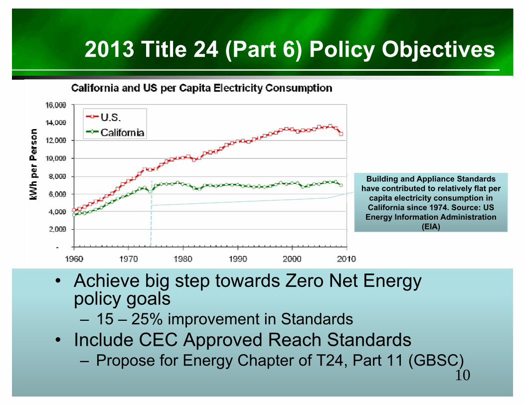
2013 Title 24 (Part 6) Policy Objectives( ) y j
Building and Appliance Standards have contributed to relatively flat per
capita electricity consumption in California since 1974. Source: US
Energy Information Administration (EIA)
• Achieve big step towards Zero Net Energy policy goalspolicy goals– 15 – 25% improvement in Standards
• Include CEC Approved Reach Standardspp– Propose for Energy Chapter of T24, Part 11 (GBSC)
10
Definitions
• “IOU”I t O d Utilit– Investor Owned Utility
• “Decouple”Ch th l ti hi b t th t f– Change the relationship between the amount of energy sold and the amount of revenue a utility makes. Decoupling means Utilities receive p grevenue from the CPUC based on meeting an energy efficiency metric.
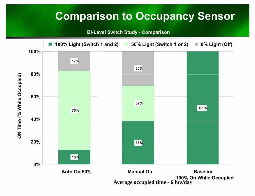
Comparison to Occupancy SensorBi-Level Switch Study - Comparison
100%100% Light (Switch 1 and 2) 50% Light (Switch 1 or 2) 0% Light (Off)
17%
30%80%
100%
)
60%
80%
e O
ccup
ied
100%70%
32%
40%
60%
e (%
Whi
le
38%20%
ON
Tim
e
13%
0%
Average occupied time - 6 hrs/day
Auto On 50% Manual On Baseline100% On While Occupied
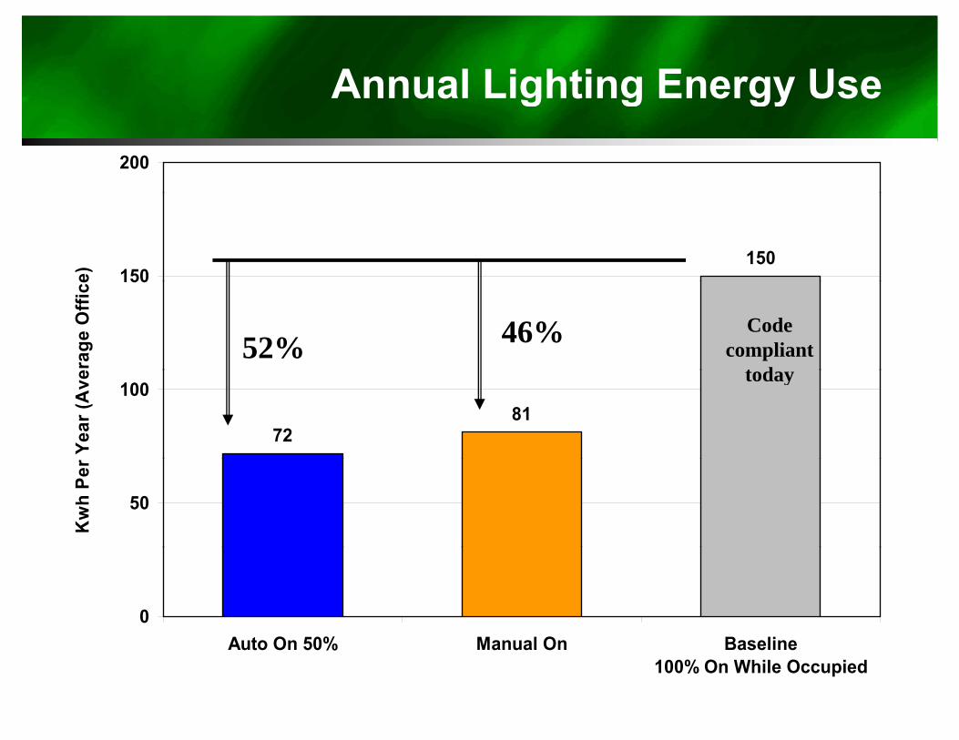
Annual Lighting Energy Use200
g g gy
150150e) 150
erag
e O
ffice
52% 46% Code compliant
t d
7281
100
Year
(Ave today
50
Kw
h Pe
r
0Auto On 50% Manual On Baseline
100% On While Occupied
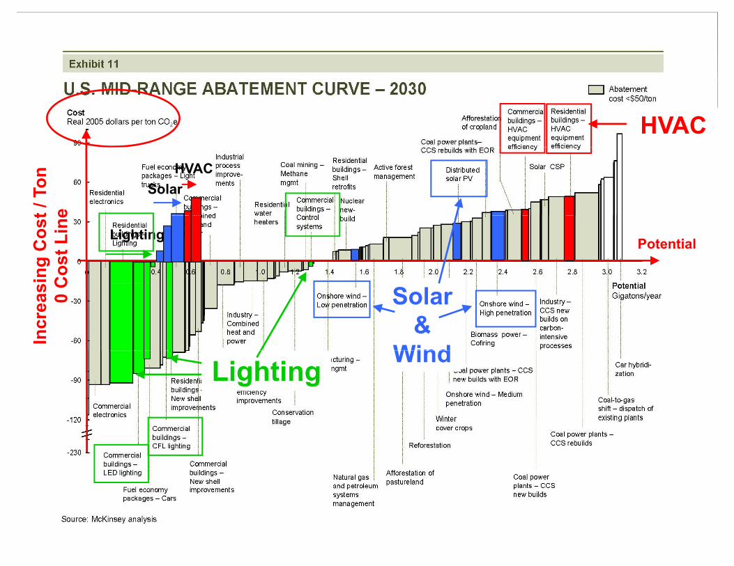
HVAC
SolarHVAC
t / T
one
Potential Lighting
ing
Cos
tC
ost L
ine
Solar &
Wind
Incr
eas 0 C
Lighting Wind
3 Methods in Title 24
• Mandate minimum automationEli i t “ t d” l t i l– Eliminate “wasted” electrical consumption
• Mandate maximum allowed watt/ft2• Mandate maximum allowed watt/ft– Ensure lower electrical envelope for
new buildingsg• Provide incentives for exceeding
current mandatory measuresy– Allow engineers to offer creative
solutions and trade energy if needed
15
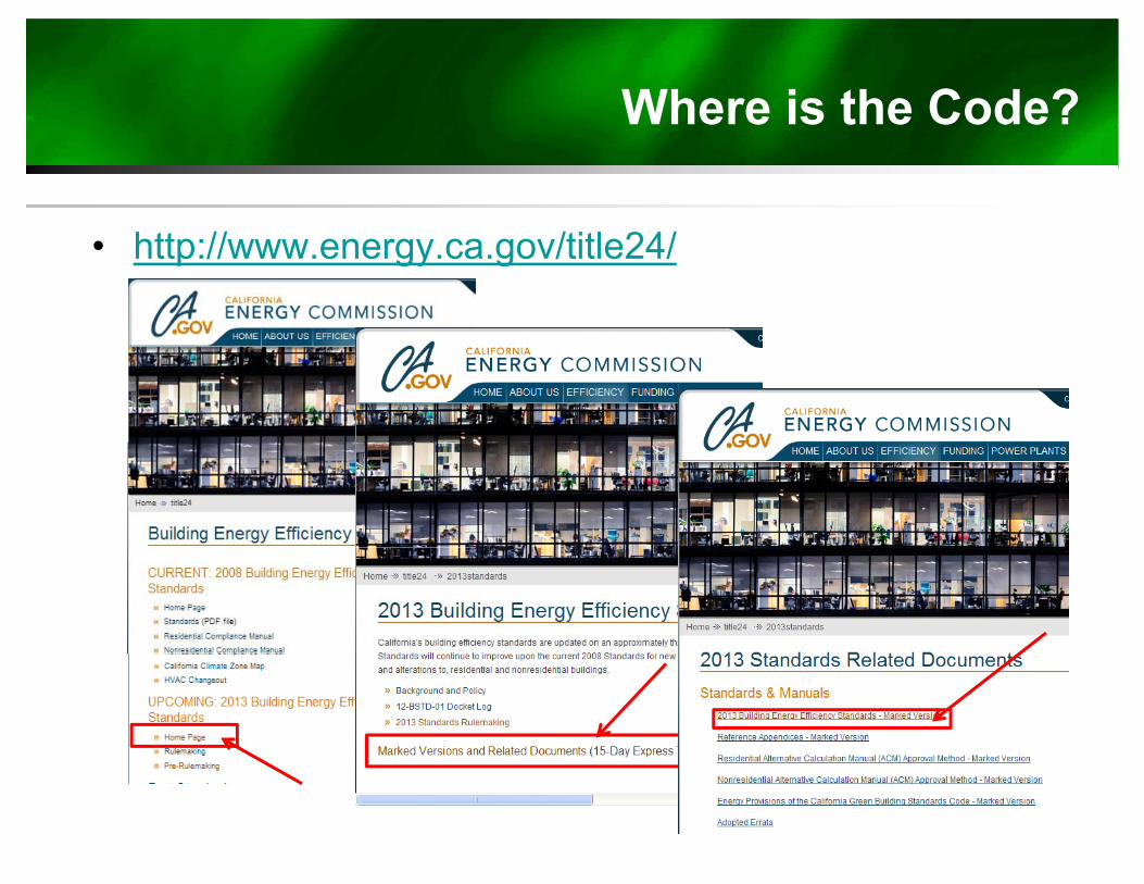
Where is the Code?
• http://www.energy.ca.gov/title24/
Major Changes from 2008 Versionj g 8
• MultiLevel “Controllable Lighting”• Plug Load requirements• Demand Response controlsp• Outdoor Lighting Changes
17
When?
• 2013 Building Energy Standards t k ff t J 1 2014 ftake effect January 1, 2014 for any site pulling a permit after that date.
18
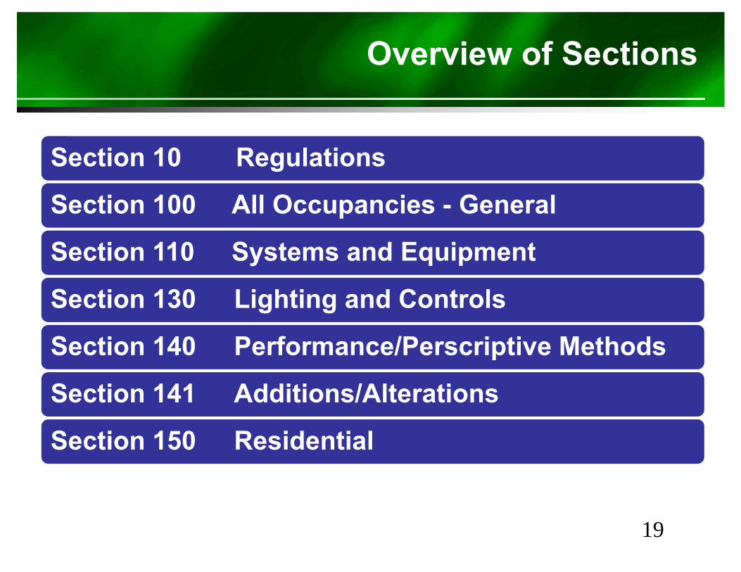
Overview of Sections
S ti 10 R l tiSection 10 Regulations
Section 100 All Occupancies - Generalp
Section 110 Systems and Equipment
Section 130 Lighting and Controls
Section 140 Performance/Perscriptive MethodsSection 140 Performance/Perscriptive Methods
Section 141 Additions/Alterations
Section 150 Residential
19
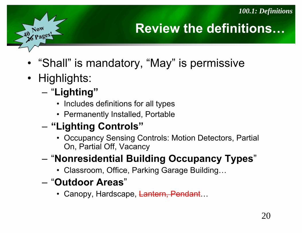
Review the definitions…100.1: Definitions
“Shall” is mandator “Ma ” is permissi e• “Shall” is mandatory, “May” is permissive• Highlights:
“Li hti ”– “Lighting”• Includes definitions for all types• Permanently Installed, PortablePermanently Installed, Portable
– “Lighting Controls”• Occupancy Sensing Controls: Motion Detectors, Partial
O P ti l Off VOn, Partial Off, Vacancy – “Nonresidential Building Occupancy Types”
• Classroom, Office, Parking Garage Building…Classroom, Office, Parking Garage Building…– “Outdoor Areas”
• Canopy, Hardscape, Lantern, Pendant…
20
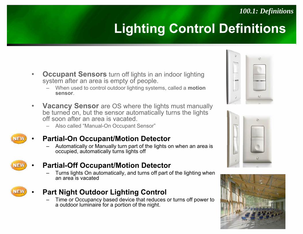
Lighting Control Definitions100.1: Definitions
g g
• Occupant Sensors turn off lights in an indoor lighting system after an area is empty of people.
– When used to control outdoor lighting systems called a motionWhen used to control outdoor lighting systems, called a motion sensor.
• Vacancy Sensor are OS where the lights must manually be turned on, but the sensor automatically turns the lights ff ft i t doff soon after an area is vacated. – Also called “Manual-On Occupant Sensor”
• Partial-On Occupant/Motion Detector A tomaticall or Man all t rn part of the lights on hen an area is– Automatically or Manually turn part of the lights on when an area is occupied, automatically turns lights off
• Partial-Off Occupant/Motion Detector– Turns lights On automatically and turns off part of the lighting when– Turns lights On automatically, and turns off part of the lighting when
an area is vacated
• Part Night Outdoor Lighting Control– Time or Occupancy based device that reduces or turns off power toTime or Occupancy based device that reduces or turns off power to
a outdoor luminaire for a portion of the night.
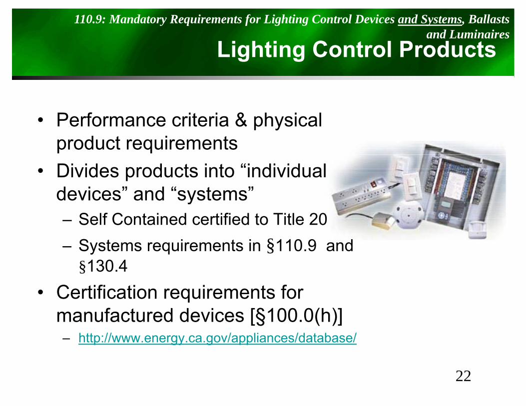
Lighting Control Products110.9: Mandatory Requirements for Lighting Control Devices and Systems, Ballasts
and Luminairesg g
• Performance criteria & physical product requirements
• Divides products into “individual devices” and “systems”y– Self Contained certified to Title 20– Systems requirements in §110.9 and y q §
§130.4• Certification requirements for q
manufactured devices [§100.0(h)]– http://www.energy.ca.gov/appliances/database/
22
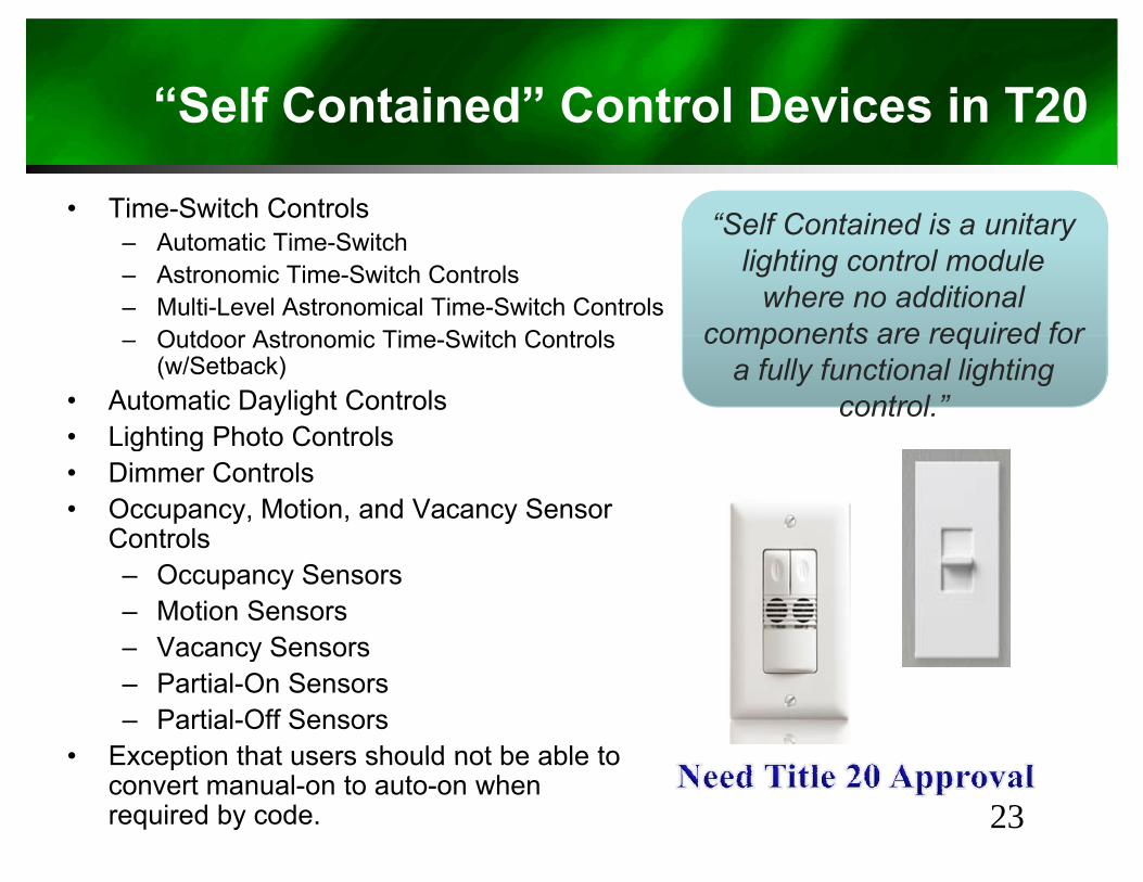
“Self Contained” Control Devices in T20
• Time-Switch Controls “Self Contained is a unitary– Automatic Time-Switch– Astronomic Time-Switch Controls– Multi-Level Astronomical Time-Switch Controls
Outdoor Astronomic Time Switch Controls
Self Contained is a unitary lighting control module
where no additional components are required for– Outdoor Astronomic Time-Switch Controls
(w/Setback)• Automatic Daylight Controls• Lighting Photo Controls
components are required for a fully functional lighting
control.”Lighting Photo Controls
• Dimmer Controls• Occupancy, Motion, and Vacancy Sensor
ControlsControls– Occupancy Sensors– Motion Sensors– Vacancy SensorsVacancy Sensors– Partial-On Sensors– Partial-Off Sensors
• Exception that users should not be able to• Exception that users should not be able to convert manual-on to auto-on when required by code. 23
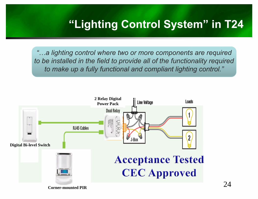
“Lighting Control System” in T24g g Sy
“ a lighting control where two or more components are required…a lighting control where two or more components are required to be installed in the field to provide all of the functionality required
to make up a fully functional and compliant lighting control.”
2 Relay Digital2 Relay Digital Power Pack
Digital Bi-level Switch
Corner-mounted PIR 24
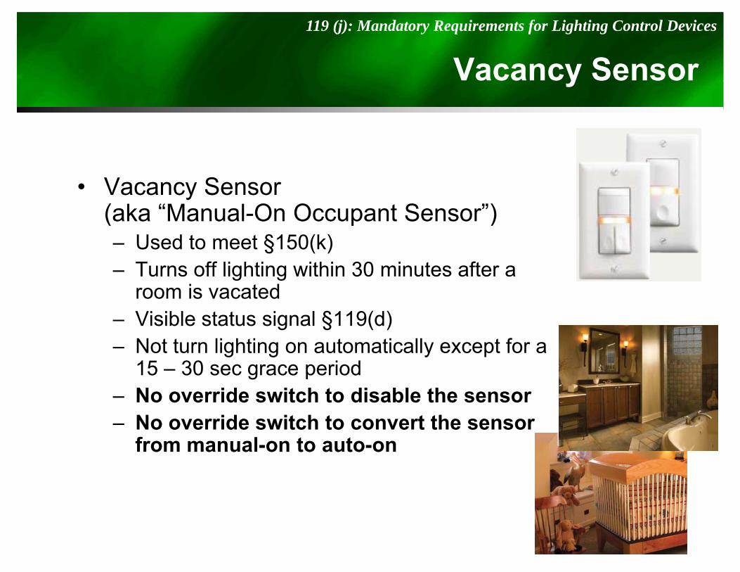
Vacancy Sensor119 (j): Mandatory Requirements for Lighting Control Devices
y S
• Vacancy Sensor(aka “Manual-On Occupant Sensor”)(aka Manual On Occupant Sensor )– Used to meet §150(k)– Turns off lighting within 30 minutes after a
i t droom is vacated– Visible status signal §119(d) – Not turn lighting on automatically except for a g g y p
15 – 30 sec grace period– No override switch to disable the sensor
No override switch to convert the sensor– No override switch to convert the sensor from manual-on to auto-on
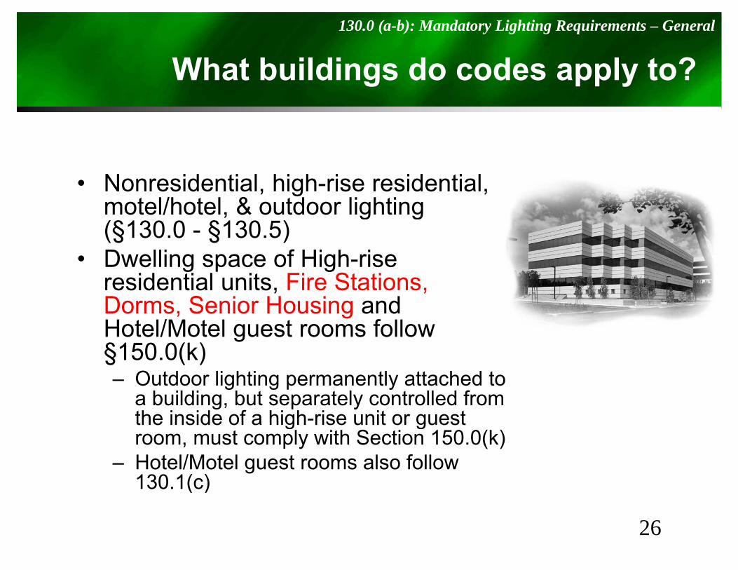
What buildings do codes apply to?130.0 (a-b): Mandatory Lighting Requirements – General
g pp y
• Nonresidential, high-rise residential, motel/hotel, & outdoor lighting , g g(§130.0 - §130.5)
• Dwelling space of High-rise residential units Fire Stationsresidential units, Fire Stations, Dorms, Senior Housing and Hotel/Motel guest rooms follow §150 0(k)§150.0(k)– Outdoor lighting permanently attached to
a building, but separately controlled from the inside of a high-rise unit or guestthe inside of a high rise unit or guest room, must comply with Section 150.0(k)
– Hotel/Motel guest rooms also follow 130.1(c)
26
( )
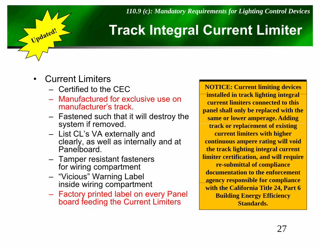
Track Integral Current Limiter110.9 (c): Mandatory Requirements for Lighting Control Devices
g
• Current Limiters– Certified to the CEC NOTICE: Current limiting devices
installed in track lighting integral– Manufactured for exclusive use on manufacturer’s track.
– Fastened such that it will destroy the system if removed
installed in track lighting integral current limiters connected to this
panel shall only be replaced with the same or lower amperage. Adding
k l f i isystem if removed.– List CL’s VA externally and
clearly, as well as internally and at Panelboard.
track or replacement of existing current limiters with higher
continuous ampere rating will void the track lighting integral current
– Tamper resistant fastenersfor wiring compartment
– “Vicious” Warning Labelinside iring compartment
limiter certification, and will require re-submittal of compliance
documentation to the enforcement agency responsible for compliance inside wiring compartment
– Factory printed label on every Panel board feeding the Current Limiters
g y p pwith the California Title 24, Part 6
Building Energy Efficiency Standards.
27
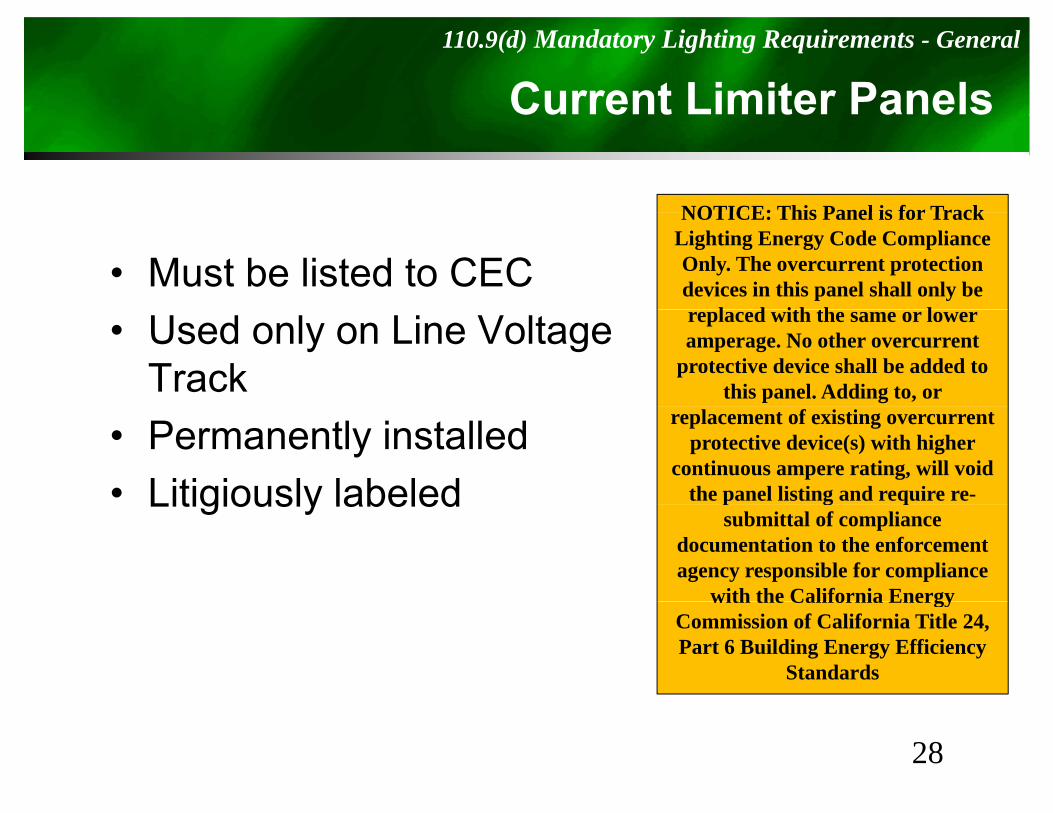
Current Limiter Panels110.9(d) Mandatory Lighting Requirements - General
NOTICE: This Panel is for Track
• Must be listed to CEC
NOTICE: This Panel is for Track Lighting Energy Code Compliance Only. The overcurrent protection devices in this panel shall only be
l d ith th l• Used only on Line Voltage Track
replaced with the same or lower amperage. No other overcurrent
protective device shall be added to this panel. Adding to, or
• Permanently installed• Litigiously labeled
replacement of existing overcurrentprotective device(s) with higher
continuous ampere rating, will void the panel listing and require re-Litigiously labeled p g q
submittal of compliance documentation to the enforcement agency responsible for compliance
with the California Energywith the California Energy Commission of California Title 24, Part 6 Building Energy Efficiency
Standards
28
LEDs in Resi Applications110.9 (e): Mandatory Requirements for Lighting Control Devices
pp
• To be High Efficacy, Resi LED Luminaries d Li ht E i h ll b C tifi d t CECand Light Engines shall be Certified to CEC
per JA-8.– If not certified, considered Low Efficacy– Non-resi LED lighting not required to be certified
29
Solar Ready Requirements110.10 (e): Mandatory Requirements for Solar Ready Buildings
S y q
• Mandates a “Solar Zone” for:– Single Family– Low-rise Multi-family– Hotel/Motel Occupancies & High Rise Multi
FamilyAll th N id ti l B ildi 3 t i l– All other Nonresidential Buildings 3 stories or less
• Includes Interconnection Pathways, Documentation, and Main Service Panel requirements
30
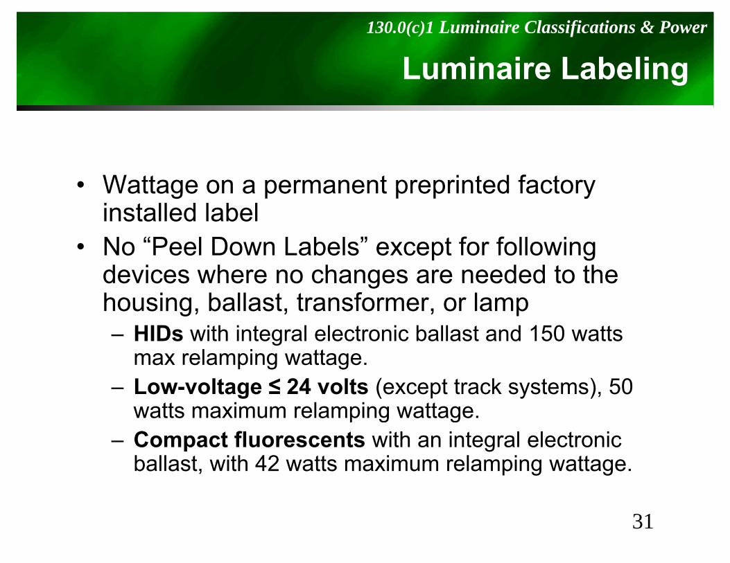
Luminaire Labeling130.0(c)1 Luminaire Classifications & Power
g
• Wattage on a permanent preprinted factory installed labelinstalled label
• No “Peel Down Labels” except for following devices where no changes are needed to thedevices where no changes are needed to the housing, ballast, transformer, or lamp– HIDs with integral electronic ballast and 150 watts
l imax relamping wattage.– Low-voltage ≤ 24 volts (except track systems), 50
watts maximum relamping wattage.watts maximum relamping wattage.– Compact fluorescents with an integral electronic
ballast, with 42 watts maximum relamping wattage.
31
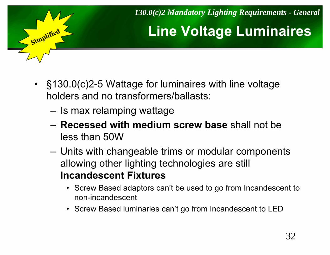
Line Voltage Luminaires130.0(c)2 Mandatory Lighting Requirements - General
g
• §130.0(c)2-5 Wattage for luminaires with line voltage holders and no transformers/ballasts:holders and no transformers/ballasts:– Is max relamping wattage– Recessed with medium screw base shall not beRecessed with medium screw base shall not be
less than 50W– Units with changeable trims or modular components
allowing other lighting technologies are still Incandescent Fixtures
• Screw Based adaptors can’t be used to go from Incandescent to• Screw Based adaptors can t be used to go from Incandescent to non-incandescent
• Screw Based luminaries can’t go from Incandescent to LED
32
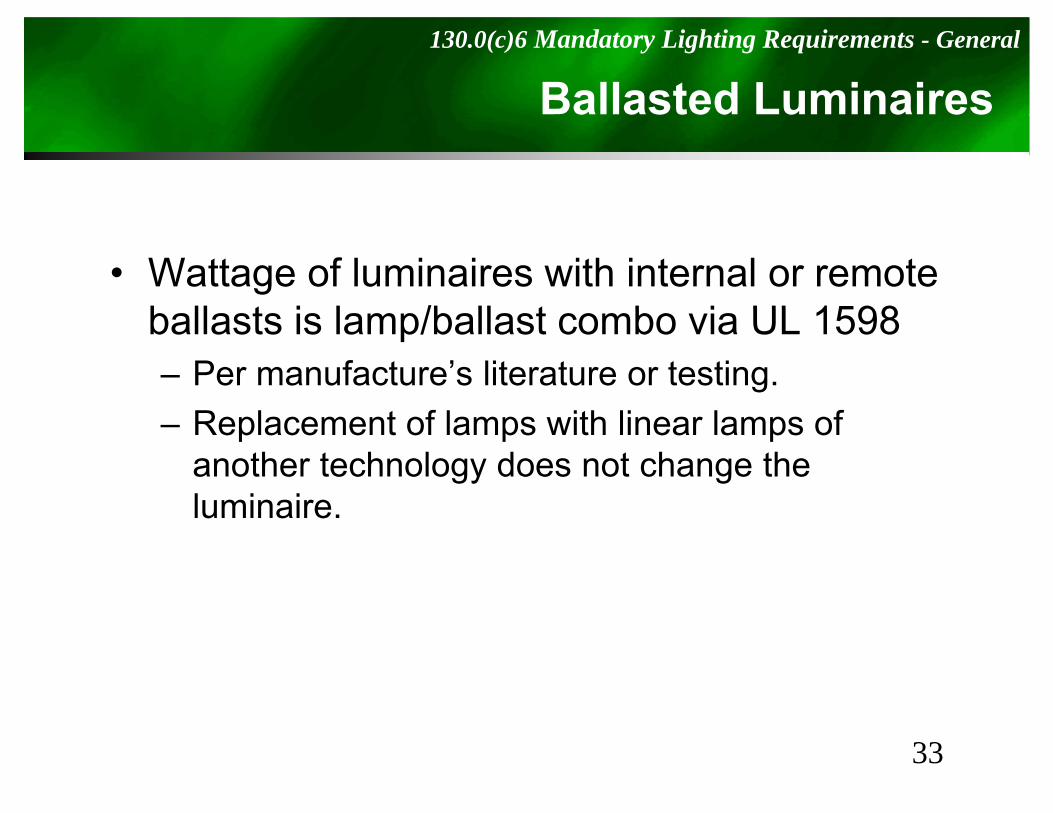
Ballasted Luminaires130.0(c)6 Mandatory Lighting Requirements - General
• Wattage of luminaires with internal or remote b ll t i l /b ll t b i UL 1598ballasts is lamp/ballast combo via UL 1598– Per manufacture’s literature or testing.– Replacement of lamps with linear lamps of
another technology does not change the luminaireluminaire.
33
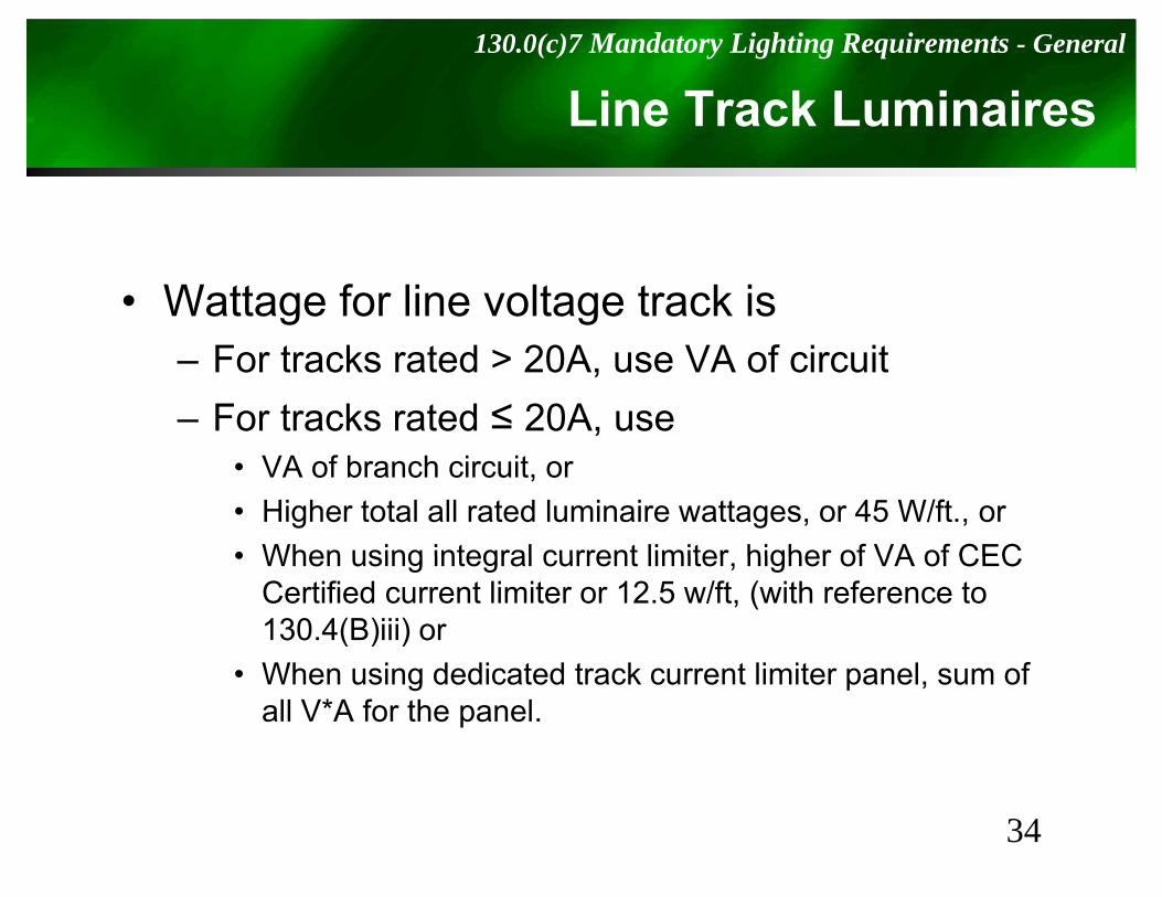
Line Track Luminaires130.0(c)7 Mandatory Lighting Requirements - General
• Wattage for line voltage track is– For tracks rated > 20A, use VA of circuit– For tracks rated ≤ 20A, use
• VA of branch circuit, or• Higher total all rated luminaire wattages, or 45 W/ft., or• When using integral current limiter higher of VA of CEC• When using integral current limiter, higher of VA of CEC
Certified current limiter or 12.5 w/ft, (with reference to 130.4(B)iii) orWh i d di t d t k t li it l f• When using dedicated track current limiter panel, sum of all V*A for the panel.
34
Luminaires & Systems with Transformers130.0(c)8 Mandatory Lighting Requirements - General
& Sy
• For LV luminaires where lamps and l i i t b dd d ith tluminaires cannot be added without re-wiring, wattage is the lamp/transformer
bcombo• For LV luminaires where lamps and
luminaires can be added without re-wiring, wattage is transformer’s max rated input wattage
35
LED and LED Light Engines130.0(c)9 Mandatory Lighting Requirements - General
g g
• Wattage for LEDs:– Maximum rated input wattage of the system, per
IES LM-79-08.N t th t LED L d t k it LED– Note that an LED Lamp does not make it an LED Fixture for compliance with Part 6.
W tt f LED S t h l i i• Wattage for LED Systems where luminaires and Light Engines can be added without re-wiring it’s power supply’s max rated inputwiring, it’s power supply’s max rated input wattage
36
Other130.0(c)10 Mandatory Lighting Requirements - General
• Wattage for all other lighting equipment shall b t d tt ti i tbe max rated wattage or operating input wattage of the system.
37
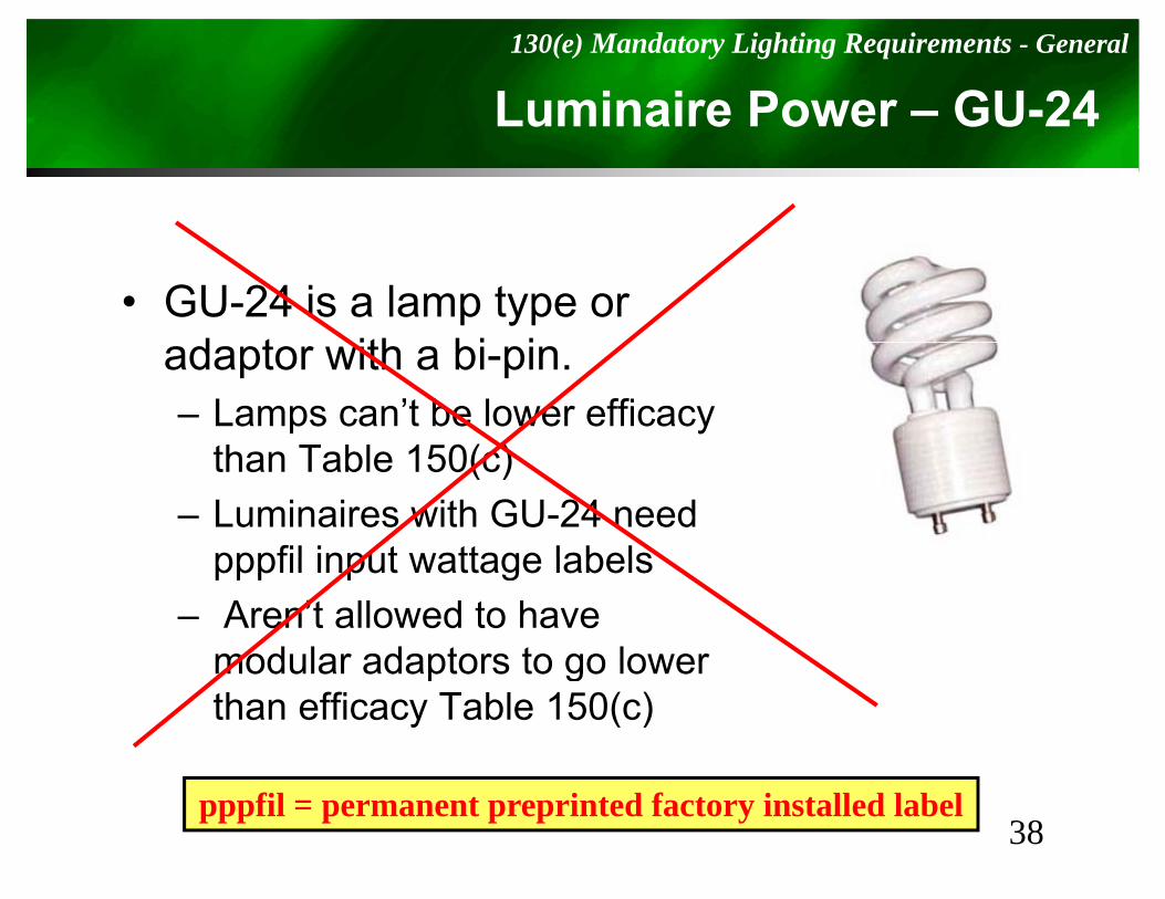
Luminaire Power – GU-24130(e) Mandatory Lighting Requirements - General
• GU-24 is a lamp type or d t ith bi iadaptor with a bi-pin.– Lamps can’t be lower efficacy
th T bl 150( )than Table 150(c)– Luminaires with GU-24 need
pppfil input wattage labelspppfil input wattage labels– Aren’t allowed to have
modular adaptors to go lowermodular adaptors to go lower than efficacy Table 150(c)
38pppfil = permanent preprinted factory installed label
Commercial / IndustrialRequirementsRequirements
130.1130.1
I d Li hti C t l th t h ll b I t ll dIndoor Lighting Controls that shall be Installed
40
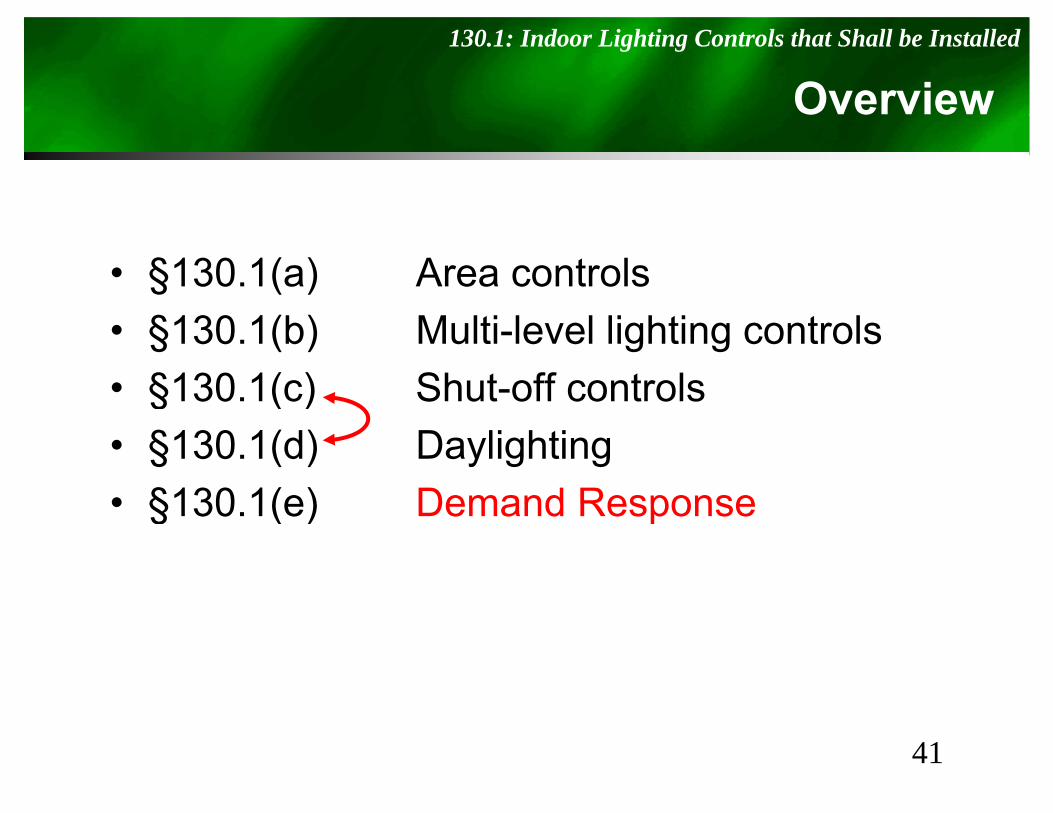
Overview130.1: Indoor Lighting Controls that Shall be Installed
• §130.1(a) Area controls• §130.1(b) Multi-level lighting controls• §130.1(c) Shut-off controls § ( )• §130.1(d) Daylighting• §130 1(e) Demand Response• §130.1(e) Demand Response
41
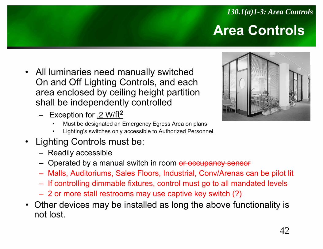
Area Controls130.1(a)1-3: Area Controls
• All luminaries need manually switched On and Off Lighting Controls, and eacharea enclosed by ceiling height partitionarea enclosed by ceiling height partition shall be independently controlled– Exception for .2 W/ft2
• Must be designated an Emergency Egress Area on plansMust be designated an Emergency Egress Area on plans• Lighting’s switches only accessible to Authorized Personnel.
• Lighting Controls must be:– Readily accessibleReadily accessible– Operated by a manual switch in room or occupancy sensor– Malls, Auditoriums, Sales Floors, Industrial, Conv/Arenas can be pilot lit– If controlling dimmable fixtures control must go to all mandated levelsIf controlling dimmable fixtures, control must go to all mandated levels– 2 or more stall restrooms may use captive key switch (?)
• Other devices may be installed as long the above functionality is not lost
42
not lost.
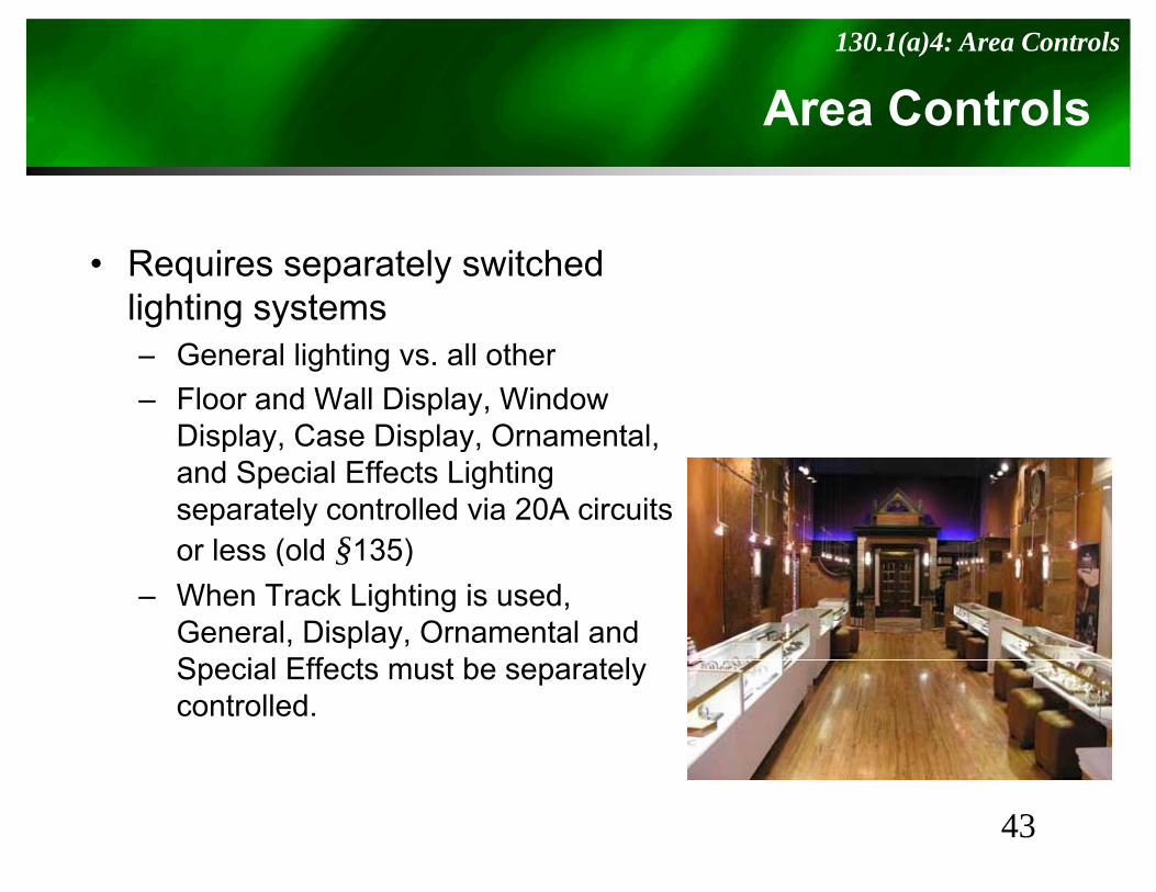
Area Controls130.1(a)4: Area Controls
• Requires separately switched lighting systems– General lighting vs. all other– Floor and Wall Display, Window
Display, Case Display, Ornamental, sp ay, Case sp ay, O a e a ,and Special Effects Lighting separately controlled via 20A circuits or less (old §135)or less (old §135)
– When Track Lighting is used, General, Display, Ornamental and S i l Eff t t b t lSpecial Effects must be separately controlled.
43

Multi-level Controls130.1(b): Multi-Level Controls
• If Area ≥ 100 ft2 and > 0.5 W/ft2– Meet control step and uniformity criteriap y
(T130.1-A)– Each luminaire shall be controlled by at
least one of following: • Manual dimming• Manual dimming, • Lumen maintenance,• Tuning,• Automatic daylighting controls, or
D d i t l• Demand responsive controls• Exceptions
– Classrooms with a connected general lighting load ≤ 0.7 W/ft2 can have at least one step between 30 70% fullW/ft2 can have at least one step between 30-70% full rated power
– Areas with a single 1- or 2-lamp luminaire
44

Table 130.1-A: Multi-Level Lighting Controls & Uniformity Reqs
Luminaire Type Minimum Steps(% full power) Uniform illuminanceyp (% full power)
Line Voltage except GU-24,Low Voltage Incandescent,LED lamps and systems (& GU-24)
Continuous dimming10 – 100% of full power
Continuous dimming
LED lamps and systems (& GU 24)
Linear/U-bent FL lamps > 13W 1. Full Power2. High (80-85%)
3. Medium (50-75%) 4 L (20 40%)
Stepped dimming,Continuous dimming, Switching alternate lamps in a l i i ( i 4)4. Low (20-40%) luminaire (min 4)
CF pin based > 20WGU-24 FL based > 20W
Continuous dimming20 – 100% of full power
Continuous dimming
Li /U b FL l 13W O 30 70% S d di iLinear/U-bent FL lamps ≤ 13WPin based CF ≤ 20WGU-24 FL ≤ 20WTrack Lighting
One step 30-70% Stepped dimming,Continuous dimming,Switching alternate lampsTrack can use multi-circuit switching
HID > 20 WInduction >25 Wand others
One step 50-70% Stepped dimming,Continuous dimming,Alternate (min 2) lamps in a luminaire
45Exempt: Spaces < 100 ft2, or ≤ 0.5 W/ft2
Classrooms ≤ 0.7Space with just a 1- or 2-lamp fixture.
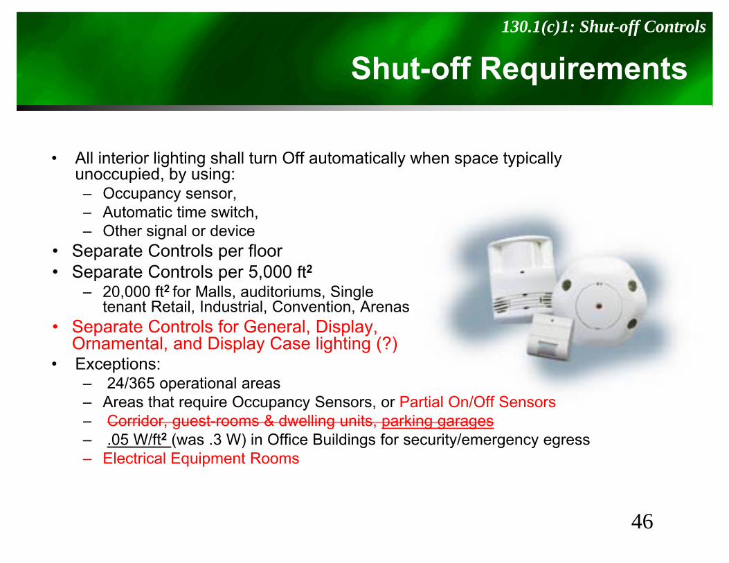
Shut-off Requirements130.1(c)1: Shut-off Controls
S q
• All interior lighting shall turn Off automatically when space typically unoccupied, by using:– Occupancy sensor, – Automatic time switchAutomatic time switch, – Other signal or device
• Separate Controls per floor• Separate Controls per 5,000 ft2
– 20,000 ft2 for Malls, auditoriums, Singletenant Retail, Industrial, Convention, Arenas
• Separate Controls for General, Display,Ornamental, and Display Case lighting (?)Ornamental, and Display Case lighting (?)
• Exceptions:– 24/365 operational areas– Areas that require Occupancy Sensors, or Partial On/Off Sensors
C id t & d lli it ki– Corridor, guest-rooms & dwelling units, parking garages– .05 W/ft2 (was .3 W) in Office Buildings for security/emergency egress– Electrical Equipment Rooms
46
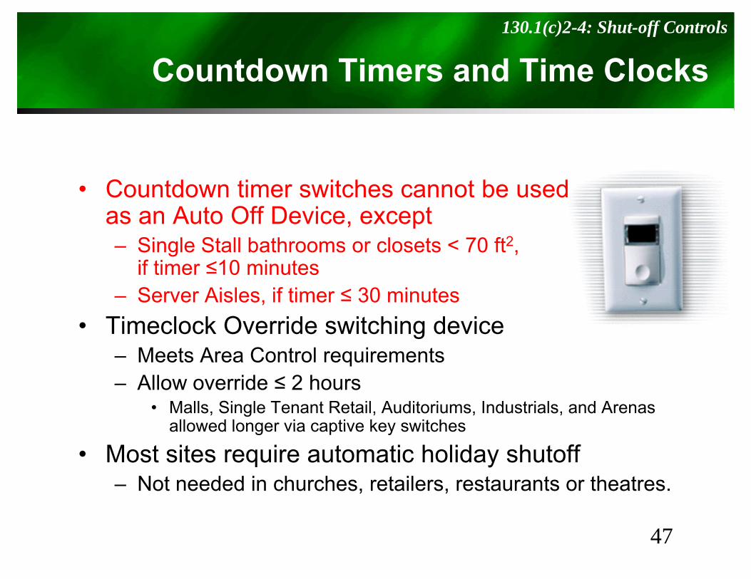
Countdown Timers and Time Clocks130.1(c)2-4: Shut-off Controls
• Countdown timer switches cannot be usedas an Auto Off Device exceptas an Auto Off Device, except – Single Stall bathrooms or closets < 70 ft2,
if timer ≤10 minutesS Ai l if ti ≤ 30 i t– Server Aisles, if timer ≤ 30 minutes
• Timeclock Override switching device– Meets Area Control requirementsMeets Area Control requirements– Allow override ≤ 2 hours
• Malls, Single Tenant Retail, Auditoriums, Industrials, and Arenas allowed longer via captive key switchesallowed longer via captive key switches
• Most sites require automatic holiday shutoff– Not needed in churches, retailers, restaurants or theatres.
47
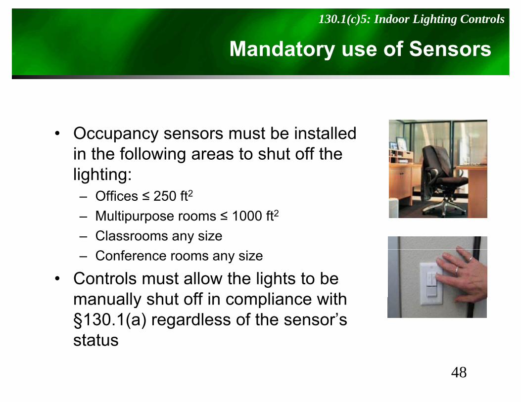
Mandatory use of Sensors130.1(c)5: Indoor Lighting Controls
y
• Occupancy sensors must be installed in the following areas to shut off thein the following areas to shut off the lighting:– Offices ≤ 250 ft2
– Multipurpose rooms ≤ 1000 ft2
– Classrooms any size– Conference rooms any size
• Controls must allow the lights to be manually shut off in compliance withmanually shut off in compliance with §130.1(a) regardless of the sensor’s statusstatus
48
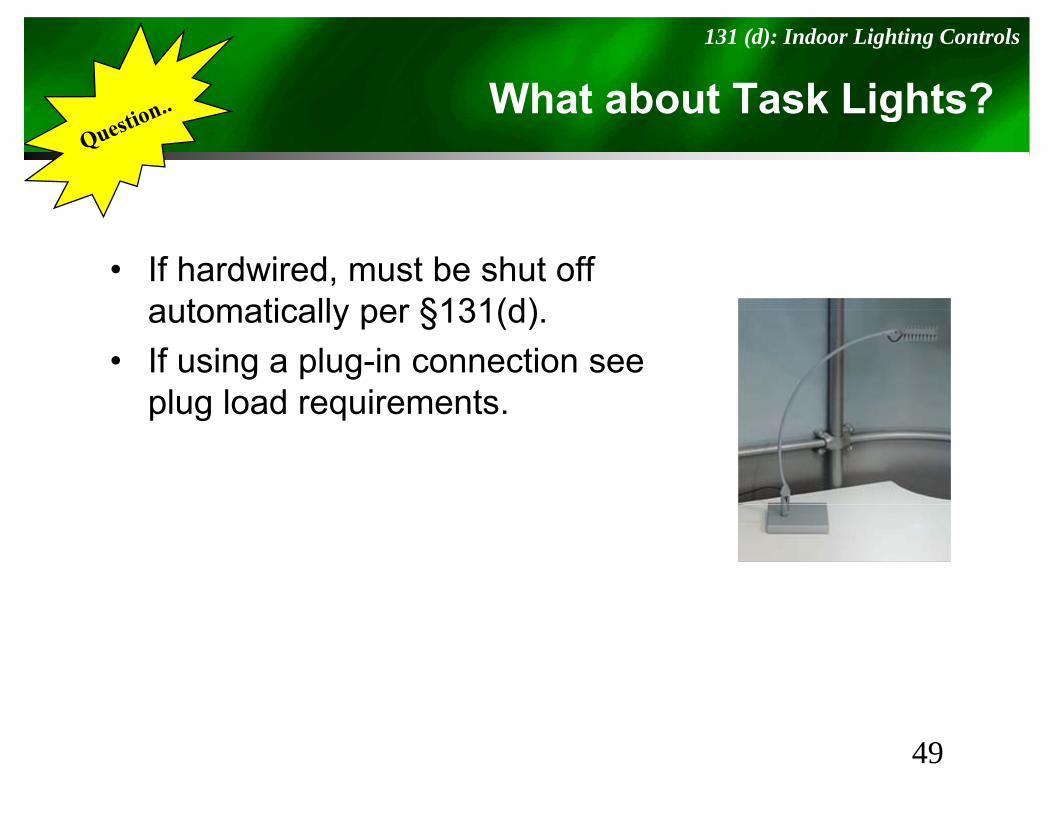
What about Task Lights?131 (d): Indoor Lighting Controls
g
• If hardwired, must be shut off automatically per §131(d)automatically per §131(d).
• If using a plug-in connection see plug load requirementsplug load requirements.
49
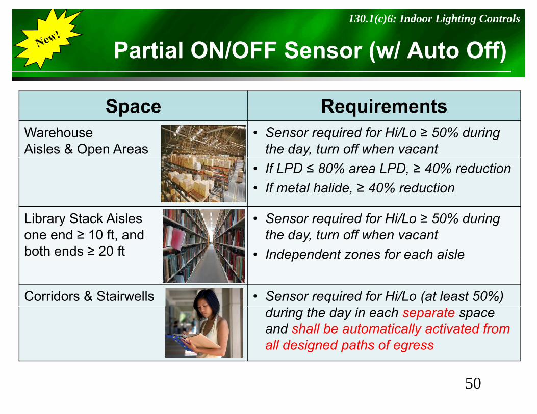
Partial ON/OFF Sensor (w/ Auto Off)130.1(c)6: Indoor Lighting Controls
S ( )
Space RequirementsSpace RequirementsWarehouseAisles & Open Areas
• Sensor required for Hi/Lo ≥ 50% during the day, turn off when vacant
• If LPD ≤ 80% area LPD, ≥ 40% reduction• If metal halide, ≥ 40% reduction
Library Stack Aislesone end ≥ 10 ft, andboth ends ≥ 20 ft
• Sensor required for Hi/Lo ≥ 50% during the day, turn off when vacant
• Independent zones for each aisleIndependent zones for each aisle
Corridors & Stairwells • Sensor required for Hi/Lo (at least 50%) during the day in each separate space and shall be automatically activated from all designed paths of egress
50
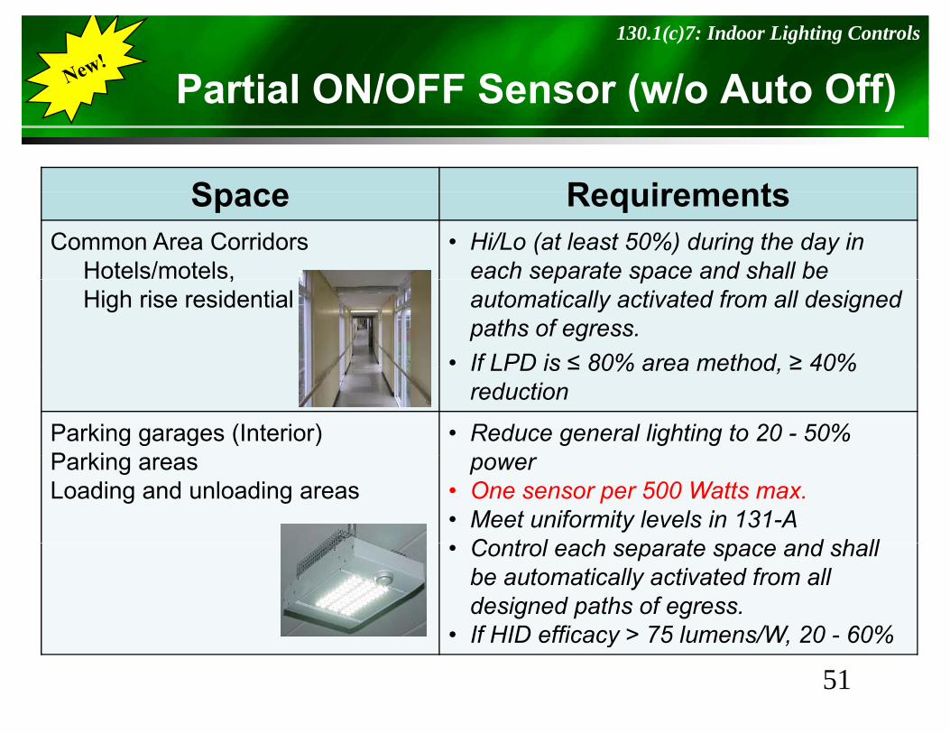
Partial ON/OFF Sensor (w/o Auto Off)130.1(c)7: Indoor Lighting Controls
S ( )
Space RequirementsSpace RequirementsCommon Area Corridors
Hotels/motels,• Hi/Lo (at least 50%) during the day in
each separate space and shall be ,High rise residential
p pautomatically activated from all designed paths of egress.
• If LPD is ≤ 80% area method ≥ 40%If LPD is ≤ 80% area method, ≥ 40% reduction
Parking garages (Interior)P ki
• Reduce general lighting to 20 - 50% Parking areasLoading and unloading areas
power• One sensor per 500 Watts max.• Meet uniformity levels in 131-A
C t l h t d h ll• Control each separate space and shall be automatically activated from all designed paths of egress.If HID efficacy > 75 lumens/W 20 60%
51• If HID efficacy > 75 lumens/W, 20 - 60%
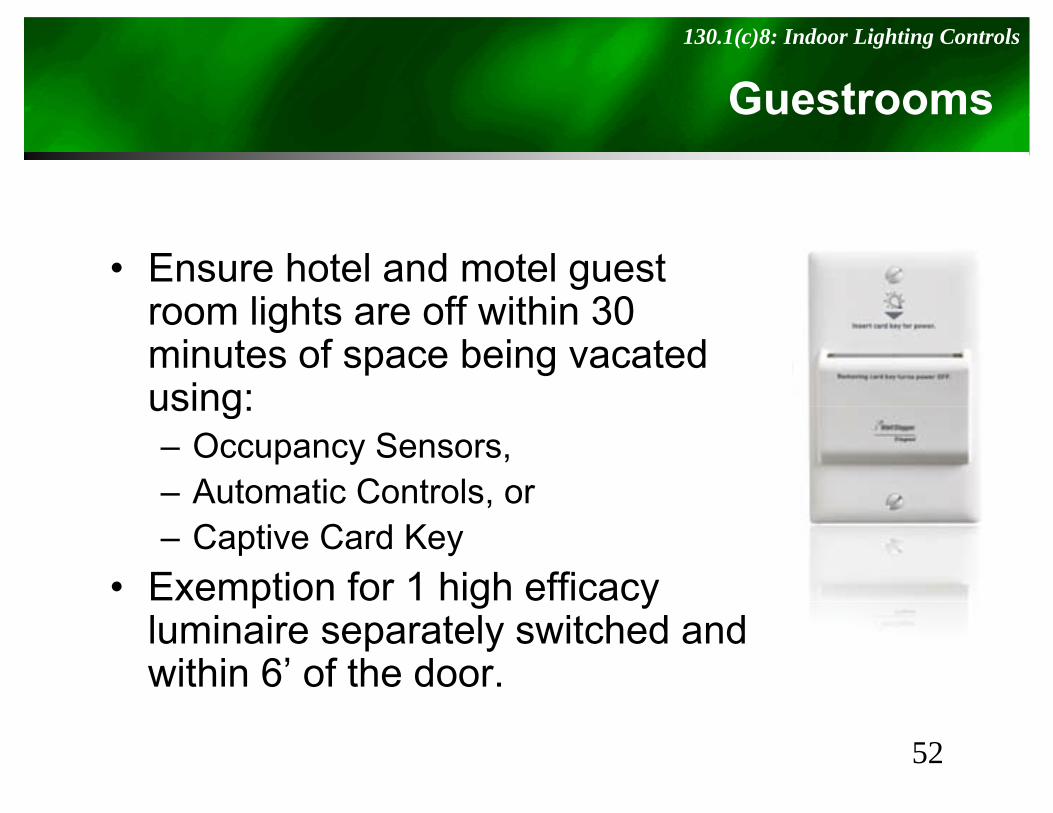
Guestrooms130.1(c)8: Indoor Lighting Controls
• Ensure hotel and motel guest room lights are off within 30room lights are off within 30 minutes of space being vacated using:using:– Occupancy Sensors,– Automatic Controls, or ,– Captive Card Key
• Exemption for 1 high efficacy p g yluminaire separately switched and within 6’ of the door.
52

Daylighting Definitions130.1(d): Daylit Areas
y g g
• Three different Daylight Zones• DO NOT double count overlapping areas
– Skylit Daylight Area – Primary Sidelit Daylight Area – Secondary Sidelit Daylight Area
53
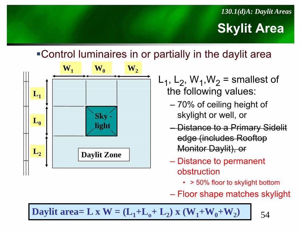
Skylit Area130.1(d)A: Daylit Areas
S y t ea
Control luminaires in or partially in the daylit area
L1, L2, W1,W2 = smallest of th f ll i l
W0W1 W2
the following values:– 70% of ceiling height of
skylight or well or
L1
Sky skylight or well, or– Distance to a Primary Sidelit
edge (includes Rooftop
L0Sky -light
Monitor Daylit), or– Distance to permanent
obstruction
L2 Daylit Zone
obstruction • > 50% floor to skylight bottom
– Floor shape matches skylight
54Daylit area= L x W = (L1+Lo+ L2) x (W1+W0+W2)
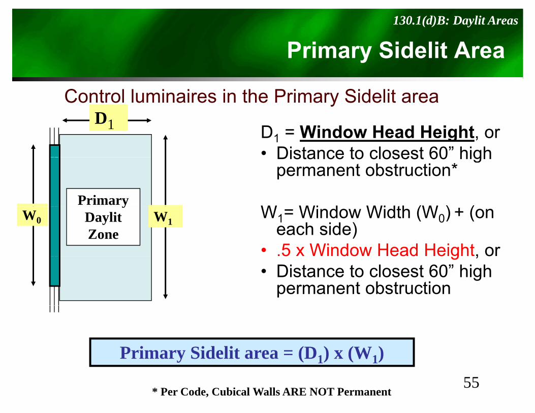
Primary Sidelit Area130.1(d)B: Daylit Areas
a y S de t ea
Control luminaires in the Primary Sidelit areaD1 D1 = Window Head Height, or
• Distance to closest 60” highDistance to closest 60 high permanent obstruction*
W Wi d Width (W ) (Primary
W1= Window Width (W0) + (on each side)
• .5 x Window Head Height, or
W0
yDaylit Zone
W1
5 do ead e g , o• Distance to closest 60” high
permanent obstruction
Primary Sidelit area = (D1) x (W1)55
Primary Sidelit area (D1) x (W1)
* Per Code, Cubical Walls ARE NOT Permanent
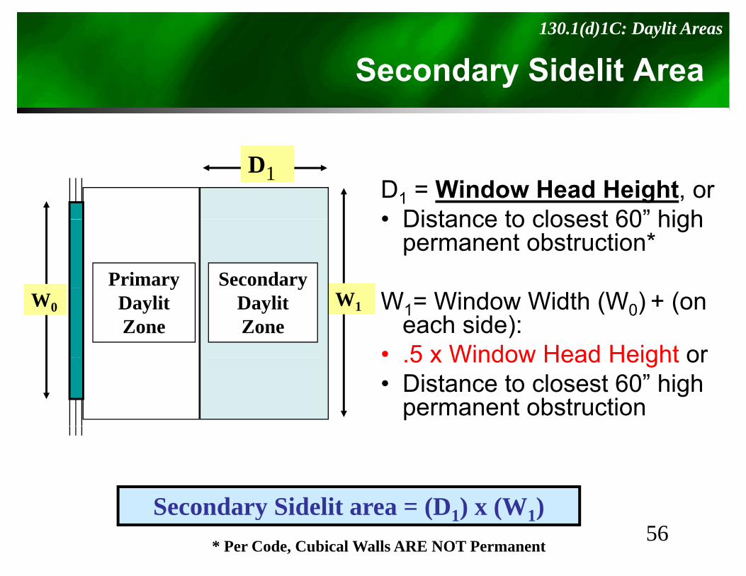
Secondary Sidelit Area130.1(d)1C: Daylit Areas
Seco da y S de t ea
D1D1 = Window Head Height, or• Distance to closest 60” high• Distance to closest 60 high
permanent obstruction*Primary Secondary
W1= Window Width (W0) + (on each side):
• 5 x Window Head Height or
W0
yDaylit Zone
W1
yDaylit Zone
.5 x Window Head Height or• Distance to closest 60” high
permanent obstruction
56Secondary Sidelit area = (D1) x (W1)
* Per Code, Cubical Walls ARE NOT Permanent
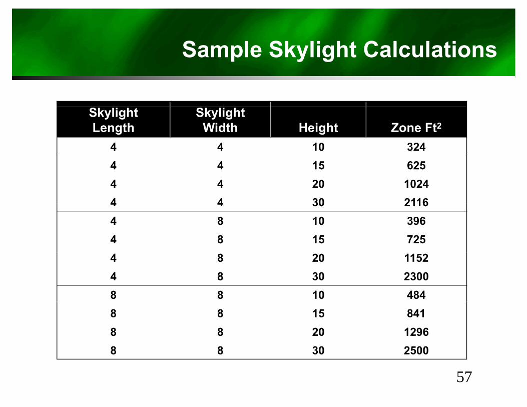
Sample Skylight CalculationsS p S y g
SkylightLength
SkylightWidth Height Zone Ft2
4 4 10 3244 4 15 6254 4 20 10244 4 30 21164 4 30 21164 8 10 3964 8 15 7254 8 20 11524 8 30 23008 8 10 4848 8 15 8418 8 20 12968 8 30 2500
57
8 8 30 2500
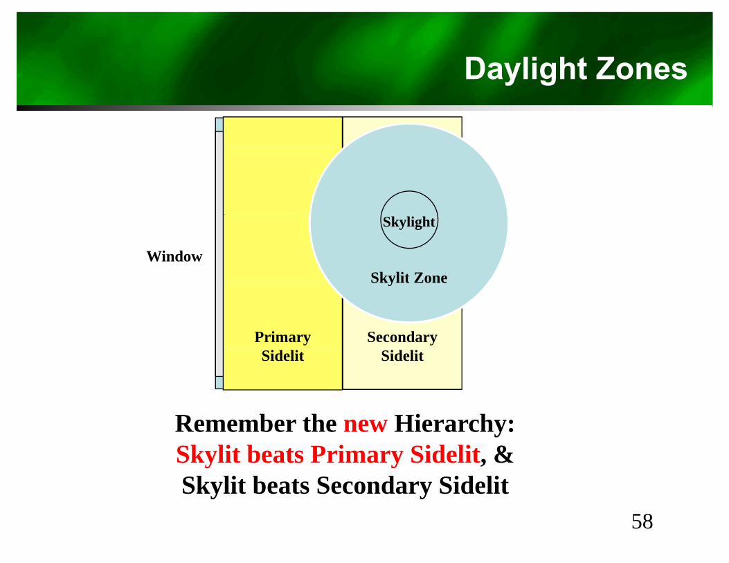
Daylight Zonesy g
Window
Skylight
Skylit Zone
SecondaryPrimary
Skylit Zone
R b th Hi h
SidelitSidelit
Remember the new Hierarchy:Skylit beats Primary Sidelit, &Skylit beats Secondary SidelitSkylit beats Secondary Sidelit
58
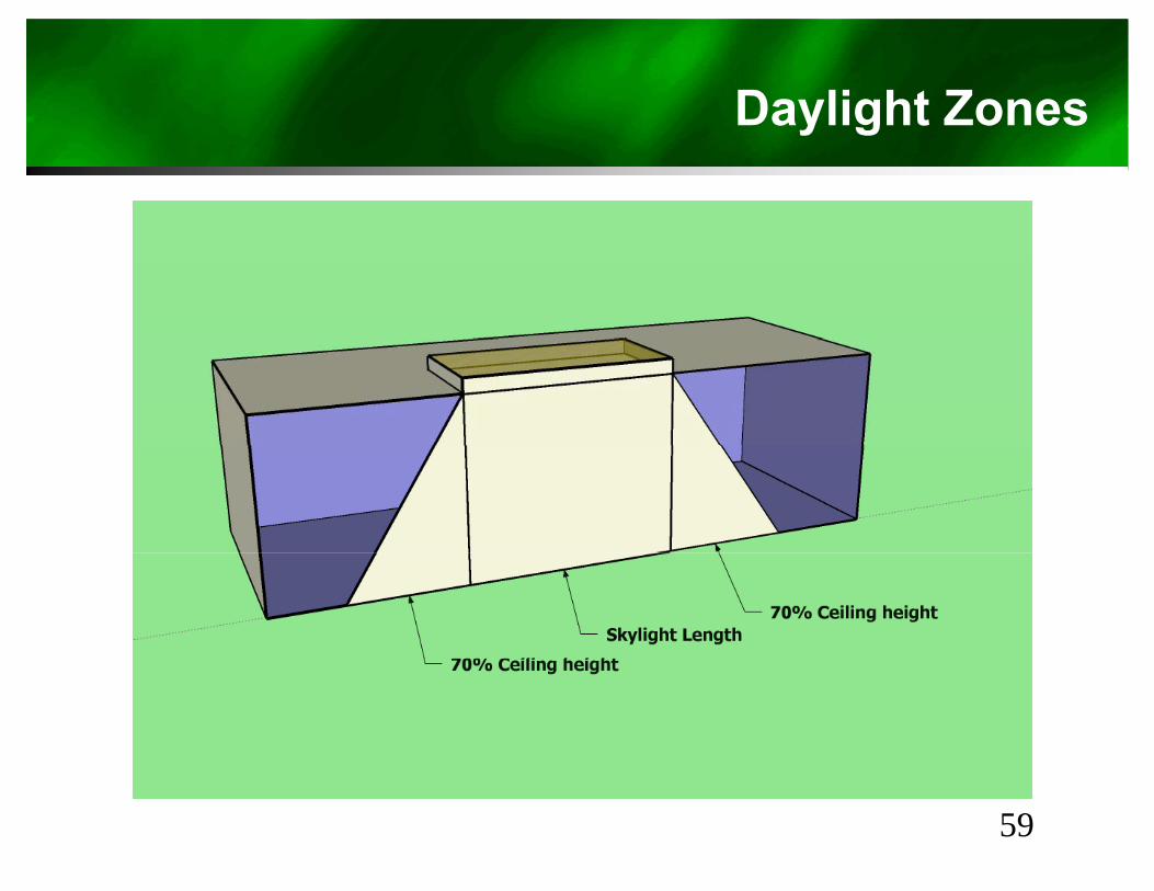
Daylight Zonesy g
59
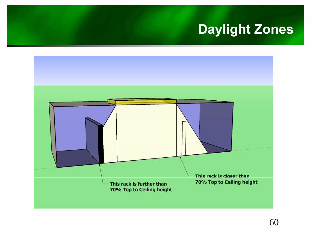
Daylight Zonesy g
60
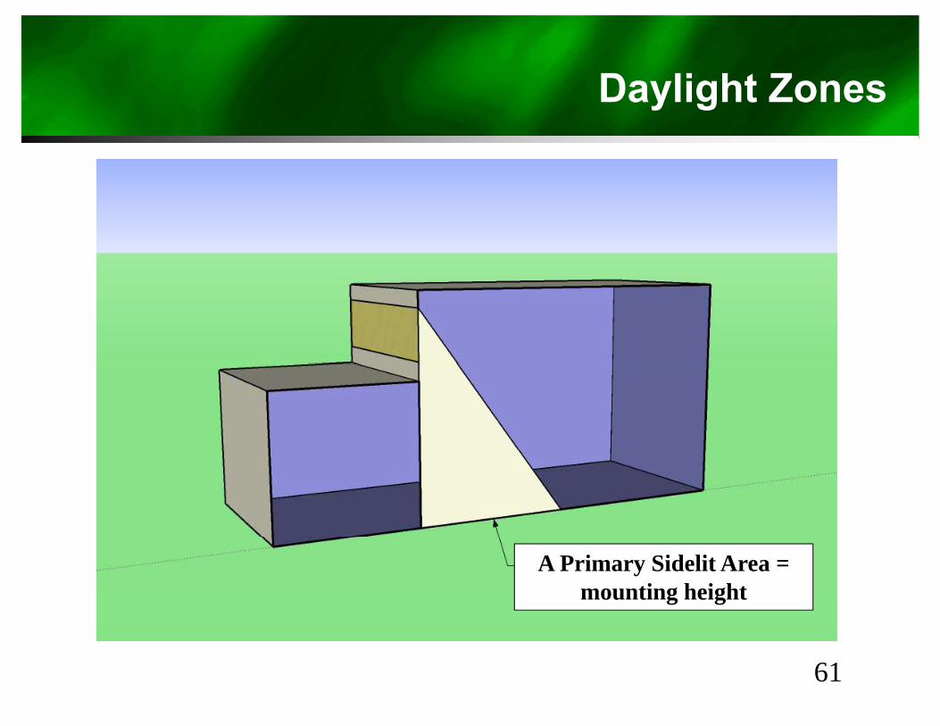
Daylight Zonesy g
A Primary Sidelit Area = mounting height
61

Daylight Zonesy g
62
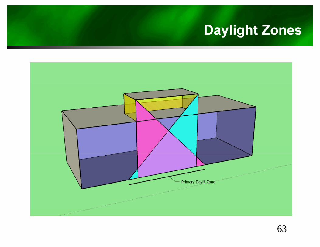
Daylight Zonesy g
63
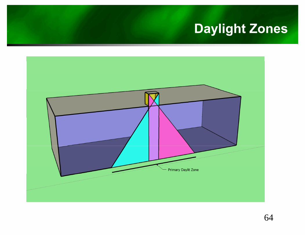
Daylight Zonesy g
64
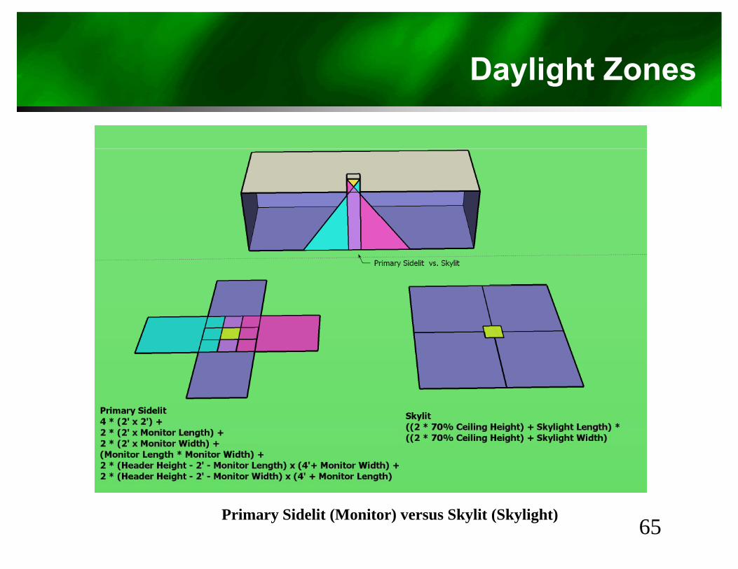
Daylight Zonesy g
Primary Sidelit (Monitor) versus Skylit (Skylight) 65
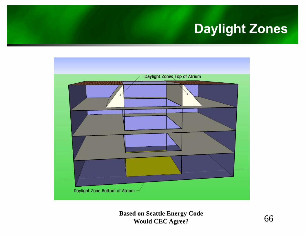
Daylight Zonesy g
Based on Seattle Energy CodeWould CEC Agree? 66
Daylight Areas130.1(d)2A-C: Daylight
y g
• General Lighting luminaires totally or partiallyi th Sk lit d li ht d/ th P iin the Skylit daylight area and/or the Primary Sidelit daylight area shall have automatic d li hti t ldaylighting controls.– Show Skylit and Primary Sidelit zones on the plans– Control luminaires in primary sidelit areas
separately from skylit areas.– WARNING!!! 140.6(d) requires control of
Secondary Sidelit fixtures for perscriptive method
67
Automatic Daylighting Control Device130.1 (d)2D: Daylight
y g g
• Install Automatic Daylighting Controls:– Photosensors and calibration controls not accessible to unauthorized people.
Daylighting controls provide multi level lighting per Table 130 1 A– Daylighting controls provide multi-level lighting per Table 130.1-A• Exemption of multi-level if LPD < 0.3 W/ft2• Exemption of multi-level if adding Skylights to a existing site
Combined illuminance from controlled lighting and daylight shall not be• Combined illuminance from controlled lighting and daylight shall not be less than controlled lighting with no daylight.
• When daylight illuminance >150% of design electric level at full power, e day g t u a ce 50% o des g e ect c e e at u po e ,the general lighting in that zone shall be reduced by minimum 65%.
• ExceptionsT t l i t ll d l li hti Sk lit P i Sid lit 120 W tt– Total installed general lighting power Skylit + Primary Sidelit zones < 120 Watts
– When glazing in room is < 24 ft2 area .
68
Parking Garage Daylighting130.1 (d)3: Daylight
g g y g g
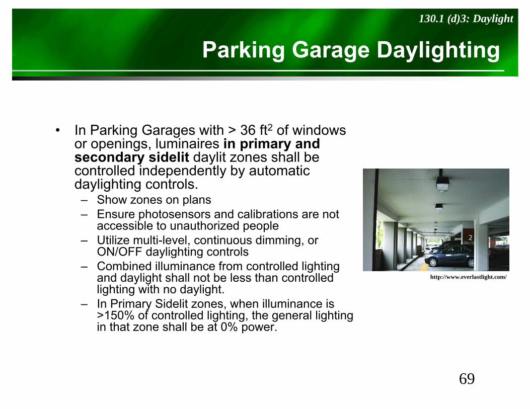
• In Parking Garages with > 36 ft2 of windows or openings, luminaires in primary and secondary sidelit daylit zones shall besecondary sidelit daylit zones shall be controlled independently by automatic daylighting controls.– Show zones on plansp– Ensure photosensors and calibrations are not
accessible to unauthorized people– Utilize multi-level, continuous dimming, or
ON/OFF daylighting controlsON/OFF daylighting controls– Combined illuminance from controlled lighting
and daylight shall not be less than controlled lighting with no daylight.In Primary Sidelit zones when illuminance is
http://www.everlastlight.com/
– In Primary Sidelit zones, when illuminance is >150% of controlled lighting, the general lighting in that zone shall be at 0% power.
69
Demand Responsive Controls130.1(e): Indoor Lighting Controls
p
• In buildings > 10,000 ft2, total lighting power shall be capable of being automatically
d d b DR i l b t l t 15%reduced by a DR signal by at least 15%– Lighting reduction shall be uniform.– Non-habitable spaces do not count toward this
requirementrequirement– Spaces < 0.5W/ ft2 shall not count toward total
power
• Per 130.5(e) DRC and equipment shall be capable of receiving and automatically responding to at least one standards basedresponding to at least one standards based messaging protocol.
70
130.2
Outdoor Lighting Controls & EquipOutdoor Lighting Controls & Equip
71
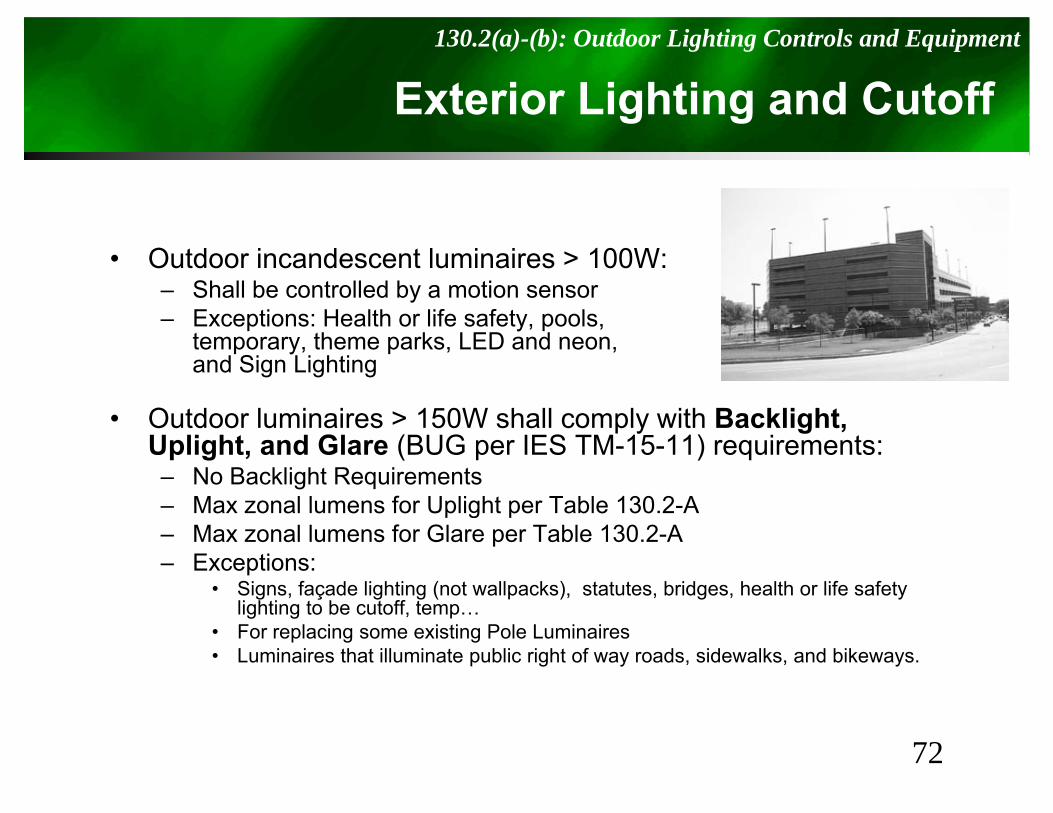
Exterior Lighting and Cutoff130.2(a)-(b): Outdoor Lighting Controls and Equipment
g g
• Outdoor incandescent luminaires > 100W:– Shall be controlled by a motion sensor
E i H l h lif f l– Exceptions: Health or life safety, pools, temporary, theme parks, LED and neon,and Sign Lighting
• Outdoor luminaires > 150W shall comply with Backlight, Uplight, and Glare (BUG per IES TM-15-11) requirements: – No Backlight Requirements
Max zonal lumens for Uplight per Table 130 2 A– Max zonal lumens for Uplight per Table 130.2-A– Max zonal lumens for Glare per Table 130.2-A– Exceptions:
• Signs, façade lighting (not wallpacks), statutes, bridges, health or life safety li hti t b t ff tlighting to be cutoff, temp…
• For replacing some existing Pole Luminaires• Luminaires that illuminate public right of way roads, sidewalks, and bikeways.
72
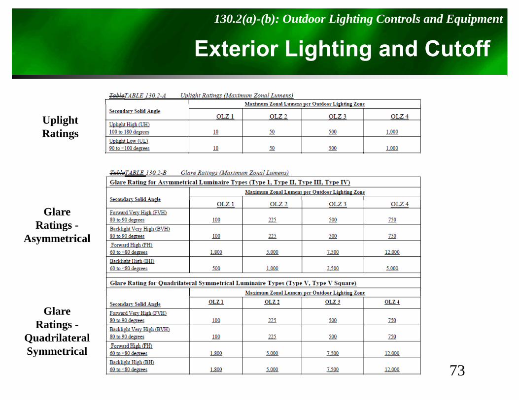
Exterior Lighting and Cutoff130.2(a)-(b): Outdoor Lighting Controls and Equipment
g g
UplightRatings
GlareRatings -
Asymmetrical
GlareRatings -
Quadrilateral
73Symmetrical
Outdoor Controls130.2(c)1-2: Outdoor Lighting Controls
• All installed outdoor lighting shall:H A t OFF b h t t l– Have Auto-OFF by a photo control or astronomical time switch;
– Be circuited and controlled to turn offBe circuited and controlled to turn off independently from other electrical loads by an automatic scheduling control.
• Exceptions:– Lights that health and life safety regulations say
t b t d ff dcannot be turned off, and – 24/7 Tunnel Lighting
74
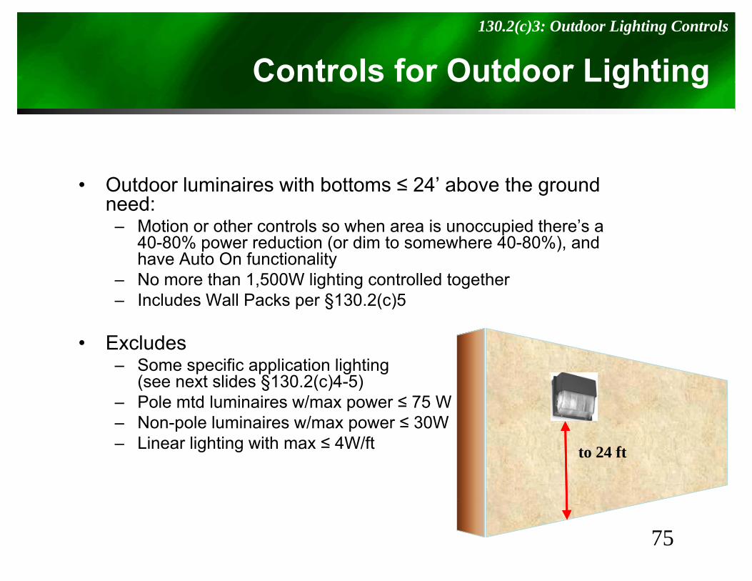
Controls for Outdoor Lighting130.2(c)3: Outdoor Lighting Controls
g g
• Outdoor luminaires with bottoms ≤ 24’ above the ground need:
M ti th t l h i i d th ’– Motion or other controls so when area is unoccupied there’s a 40-80% power reduction (or dim to somewhere 40-80%), and have Auto On functionality
– No more than 1,500W lighting controlled together– Includes Wall Packs per §130.2(c)5
• ExcludesS ifi li ti li hti– Some specific application lighting(see next slides §130.2(c)4-5)
– Pole mtd luminaires w/max power ≤ 75 W– Non-pole luminaires w/max power ≤ 30Wp p– Linear lighting with max ≤ 4W/ft to 24 ft
75
Outdoor Sales Frontage, Lots & Canopies130.2(c)4: Outdoor Lighting Controls
S g , & p
• Install automatic lighting controls to meet:– A distributed “part-night” device, or– Motion sensors capable of automatically
d i li hti b t 40 80% d hi hreducing lighting power by at 40-80%, and which have auto-on functionality.
P t Ni ht O td Li hti C t l i tiPart-Night Outdoor Lighting Control is a time or occupancy-based system programmed to reduce power or turn off an
outdoor luminaire for a portion of the night
76
Façade, Ornamental Hardscape & Dining130.2(c)5: Outdoor Lighting Controls
ç , p & g
• Install automatic lighting controls that meet the following:the following:– A distributed part-night device, or
Motion sensors capable of automatically– Motion sensors capable of automatically reducing lighting power by at least 40 – 80%, and which have auto-on functionality
– A centralized time-based zone switching capable of automatically reducing lighting power by at least 50%least 50%.
• Does not include Wall Packs
77
Controls for all Signs130.3(a): Sign Lighting Controls
S g
• Indoor Sign lighting must have an Automatic Ti S it h A t i l Ti it hTime Switch or Astronomical Time switch
• Outdoor Sign lighting must have a photo control and time switch, or astronomical time switch
• Exception for Outdoor signs in tunnels and large covered area the require illumination during daylight hours
78
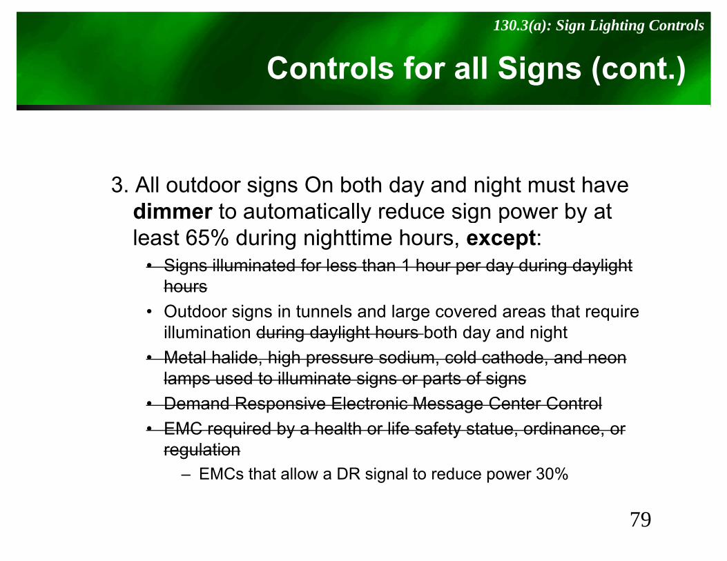
Controls for all Signs (cont.)130.3(a): Sign Lighting Controls
S g ( )
3. All outdoor signs On both day and night must have dimmer to automatically reduce sign power by atdimmer to automatically reduce sign power by at least 65% during nighttime hours, except:
• Signs illuminated for less than 1 hour per day during daylight hhours
• Outdoor signs in tunnels and large covered areas that require illumination during daylight hours both day and night
• Metal halide, high pressure sodium, cold cathode, and neon lamps used to illuminate signs or parts of signs
• Demand Responsive Electronic Message Center Control• EMC required by a health or life safety statue, ordinance, or
regulation– EMCs that allow a DR signal to reduce power 30%g p
79
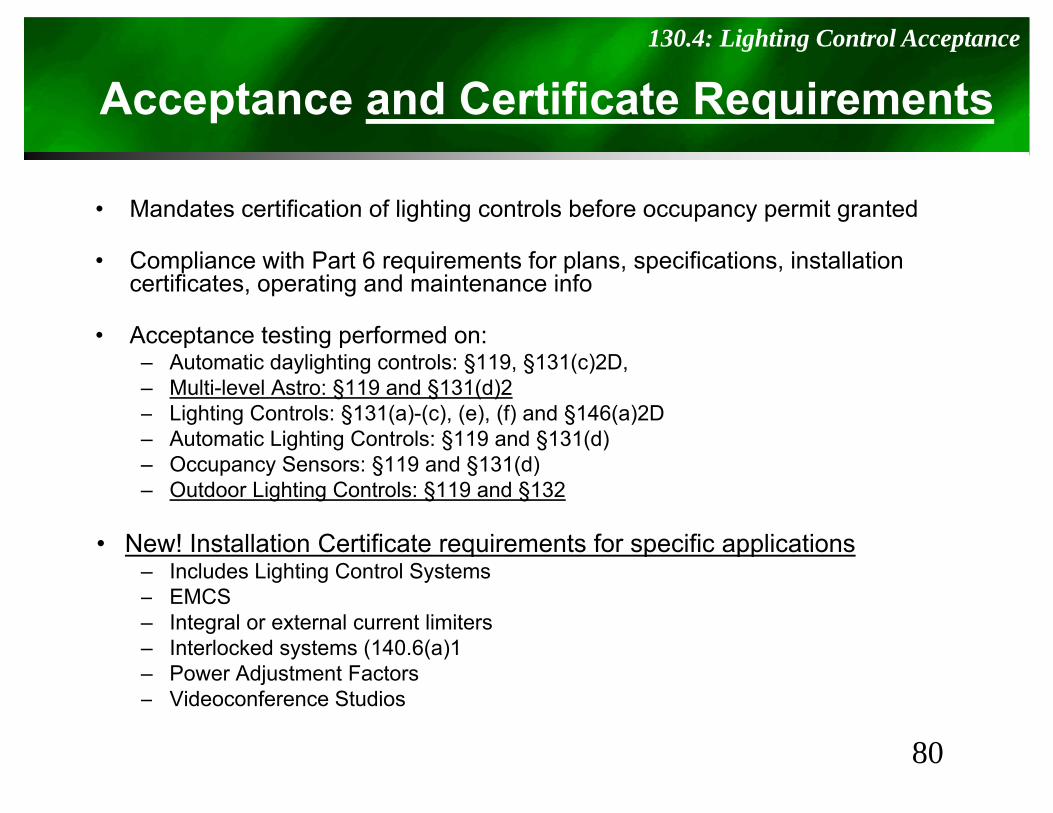
Acceptance and Certificate Requirements130.4: Lighting Control Acceptance
p q
• Mandates certification of lighting controls before occupancy permit grantedMandates certification of lighting controls before occupancy permit granted
• Compliance with Part 6 requirements for plans, specifications, installation certificates, operating and maintenance info
• Acceptance testing performed on:– Automatic daylighting controls: §119, §131(c)2D, – Multi-level Astro: §119 and §131(d)2
Li hti C t l §131( ) ( ) ( ) (f) d §146( )2D– Lighting Controls: §131(a)-(c), (e), (f) and §146(a)2D– Automatic Lighting Controls: §119 and §131(d)– Occupancy Sensors: §119 and §131(d)– Outdoor Lighting Controls: §119 and §132
• New! Installation Certificate requirements for specific applications– Includes Lighting Control Systems– EMCSEMCS– Integral or external current limiters– Interlocked systems (140.6(a)1– Power Adjustment Factors
Videoconference Studios
80
– Videoconference Studios
130.5130.5
El t i l P Di t ib ti S tElectrical Power Distribution Systems
81
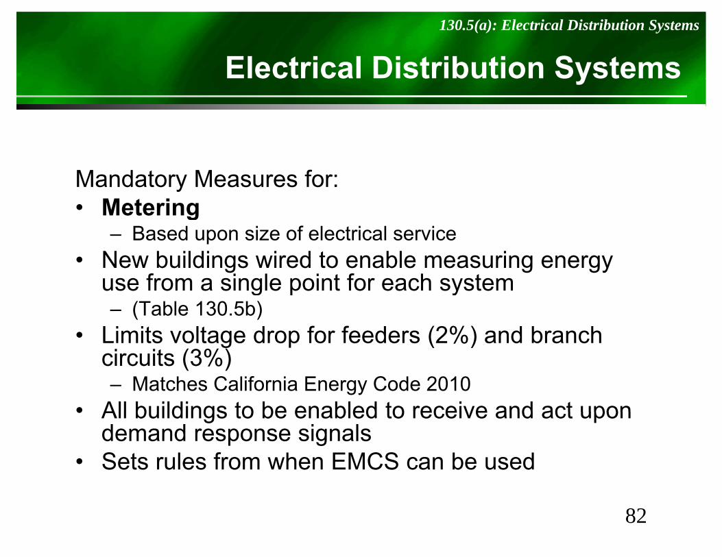
Electrical Distribution Systems130.5(a): Electrical Distribution Systems
Sy
Mandatory Measures for:• MeteringMetering
– Based upon size of electrical service• New buildings wired to enable measuring energy
use from a single point for each systemuse from a single point for each system– (Table 130.5b)
• Limits voltage drop for feeders (2%) and branch g p ( )circuits (3%)– Matches California Energy Code 2010
• All buildings to be enabled to receive and act upon• All buildings to be enabled to receive and act upon demand response signals
• Sets rules from when EMCS can be used
82
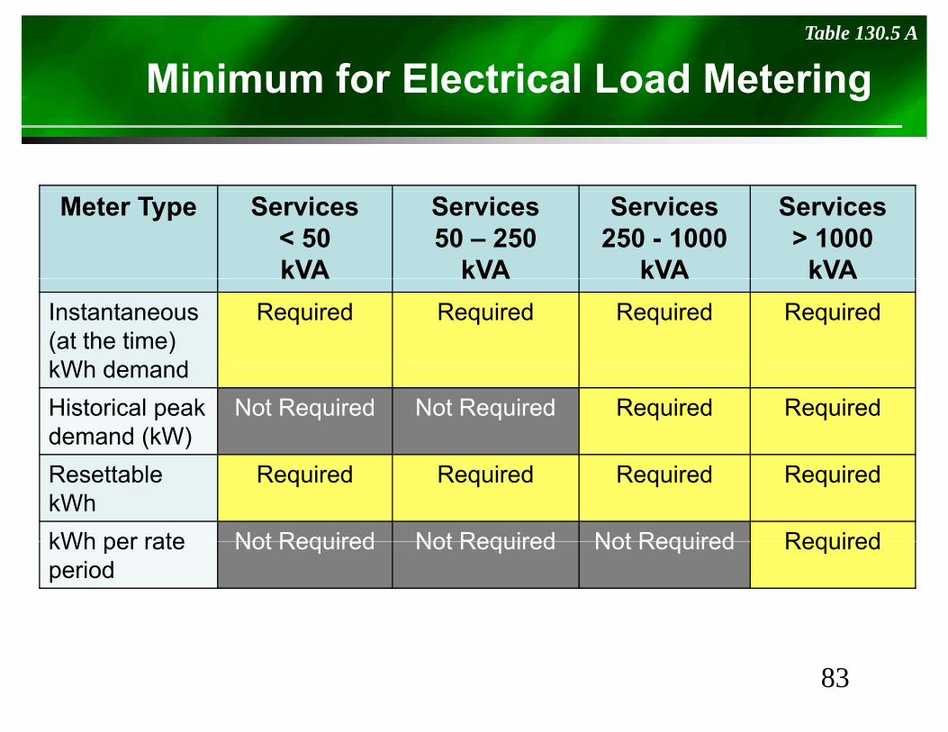
Minimum for Electrical Load Metering Table 130.5 A
Meter Type Services< 50kVA
Services50 – 250
kVA
Services250 - 1000
kVA
Services> 1000
kVAkVA kVA kVA kVAInstantaneous (at the time) kWh demand
Required Required Required Required
kWh demandHistorical peak demand (kW)
Not Required Not Required Required Required
ResettablekWh
Required Required Required Required
kWh per rate Not Required Not Required Not Required RequiredkWh per rate period
Not Required Not Required Not Required Required
83
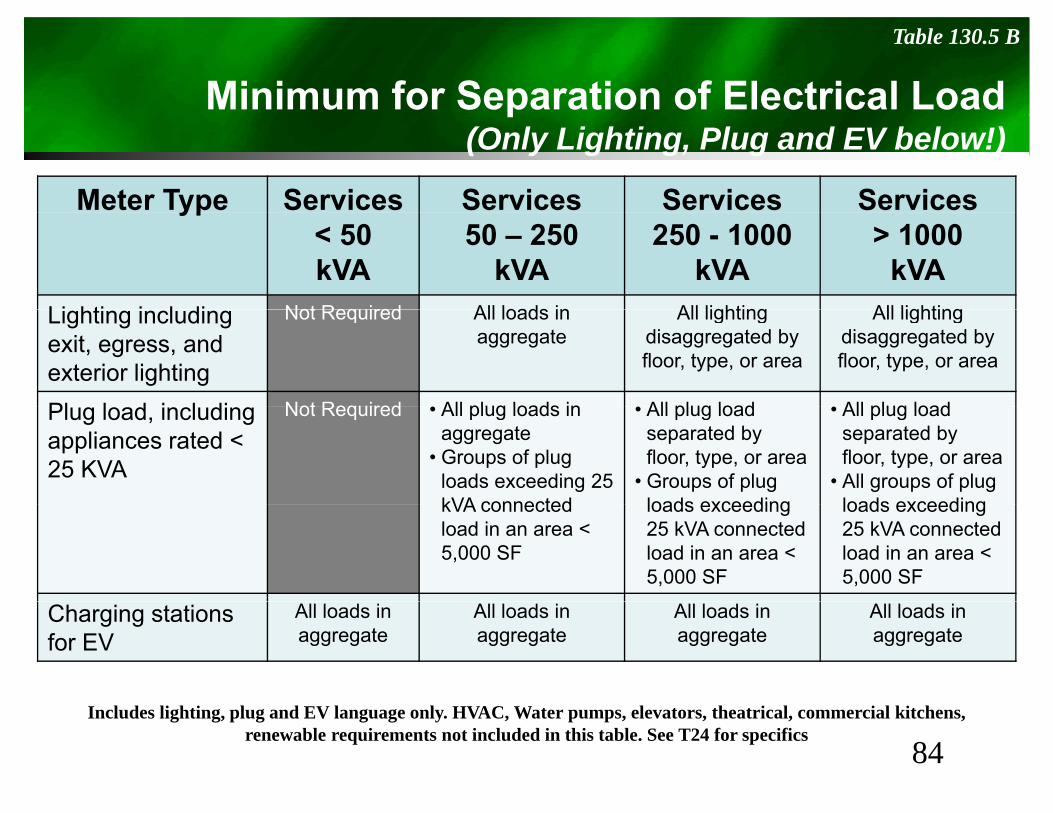
Minimum for Separation of Electrical LoadTable 130.5 B
p(Only Lighting, Plug and EV below!)
Meter Type Services Services Services Servicesyp< 50kVA
50 – 250kVA
250 - 1000 kVA
> 1000kVA
Li hti i l di Not Required All loads in All lighting All lightingLighting includingexit, egress, and exterior lighting
Not Required All loads in aggregate
All lighting disaggregated by floor, type, or area
All lighting disaggregated by floor, type, or area
Pl l d i l di Not Required • All plug loads in • All plug load • All plug loadPlug load, including appliances rated < 25 KVA
Not Required • All plug loads in aggregate
• Groups of plug loads exceeding 25 kVA connected
• All plug load separated by floor, type, or area
• Groups of plug loads exceeding
• All plug load separated by floor, type, or area
• All groups of plug loads exceedingkVA connected
load in an area < 5,000 SF
loads exceeding 25 kVA connected load in an area < 5,000 SF
loads exceeding 25 kVA connected load in an area < 5,000 SF
Charging stations for EV
All loads in aggregate
All loads in aggregate
All loads in aggregate
All loads in aggregate
84Includes lighting, plug and EV language only. HVAC, Water pumps, elevators, theatrical, commercial kitchens,
renewable requirements not included in this table. See T24 for specifics
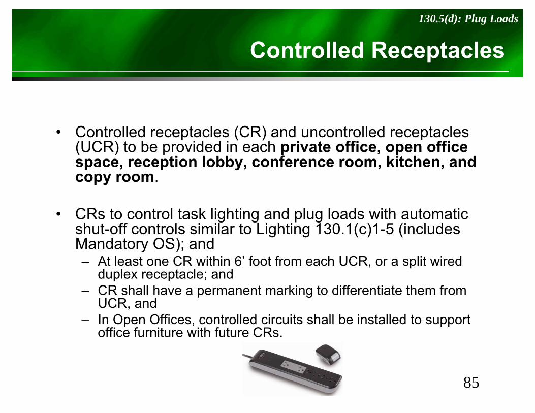
Controlled Receptacles130.5(d): Plug Loads
p
• Controlled receptacles (CR) and uncontrolled receptacles (UCR) to be provided in each private office, open office
ti l bb f kit h dspace, reception lobby, conference room, kitchen, and copy room.
• CRs to control task lighting and plug loads with automatic shut-off controls similar to Lighting 130.1(c)1-5 (includes Mandatory OS); and
A l CR i hi 6’ f f h UCR li i d– At least one CR within 6’ foot from each UCR, or a split wired duplex receptacle; and
– CR shall have a permanent marking to differentiate them from UCR andUCR, and
– In Open Offices, controlled circuits shall be installed to support office furniture with future CRs.
85
Controlled Receptacles130.5(d): Plug Loads
p
• In Hotel and motel guest rooms, at least 50% of receptacles shall be Auto Off via sensors,of receptacles shall be Auto Off via sensors, captive key switches or automatic controls so they are off within 30 minutes of vacancy
• Plug in strips that use occupancy sensors shall not be used to comply with this codenot be used to comply with this code– Exception for workstations with permanent integral
OS units
• Exceptions for fridges, water dispensers, clocks, copy room machinery, and above 20Amp.py y, p
86
Compliance Road Choice140.0: Performance vs. Prescriptive approaches.
p
• Performance Method based on comparison of TDV
Performance vs. PerscriptivePerformance Method based on comparison of TDV energy against energy budget from §140.1 calculated with a CEC approved software.pp– Time Dependant Valuation (TDV) energy is the time
varying energy used by the buildings, including space conditioning water heating lighting and mechanicalconditioning, water heating, lighting, and mechanical ventilation.
– TDV varies for each hour of the year, and energy type, by climate zone, and building type.
• Prescriptive is per sections §140.2 - §140.8
87
Prescriptive Requirements140.2: Prescriptive Approach
p q
• When using the Prescriptive method, buildings must meet the following:meet the following:– Building Envelope complies with §140.3(a), (b) and
sometimes (c)( )– Space Conditioning complies with §140.4– Service Water-heating complies with §140.5– Lighting System complies with §140.6– Outdoor Lighting System complies with §140.7– Interior and Exterior signs comply with §140.8– Covered processes that comply with §140.9
88
Skylights140.3(a) 6: Minimum Skylight Areas
S y g
• Skylights shall not have an area greater than 5% f th t i f5% of the gross exterior roof area – Exception: 10% for atria > 55 ft high
• Skylights must meet other requirements– U-factor– Solar Heat Gain coefficients– Area-Weighted Performance Rating VT– Material or diffuser Haze value >90%
89
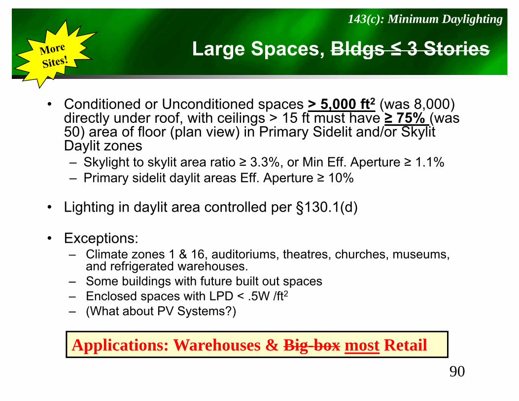
Large Spaces, Bldgs ≤ 3 Stories143(c): Minimum Daylighting
g p , g
• Conditioned or Unconditioned spaces > 5 000 ft2 (was 8 000)• Conditioned or Unconditioned spaces > 5,000 ft (was 8,000) directly under roof, with ceilings > 15 ft must have ≥ 75% (was 50) area of floor (plan view) in Primary Sidelit and/or SkylitDaylit zonesy– Skylight to skylit area ratio ≥ 3.3%, or Min Eff. Aperture ≥ 1.1%– Primary sidelit daylit areas Eff. Aperture ≥ 10%
• Lighting in daylit area controlled per §130.1(d)
• Exceptions:– Climate zones 1 & 16, auditoriums, theatres, churches, museums,
and refrigerated warehouses.– Some buildings with future built out spaces– Enclosed spaces with LPD < 5W /ft2– Enclosed spaces with LPD < .5W /ft– (What about PV Systems?)
Applications: Warehouses & Big box most Retail90
Applications: Warehouses & Big-box most Retail
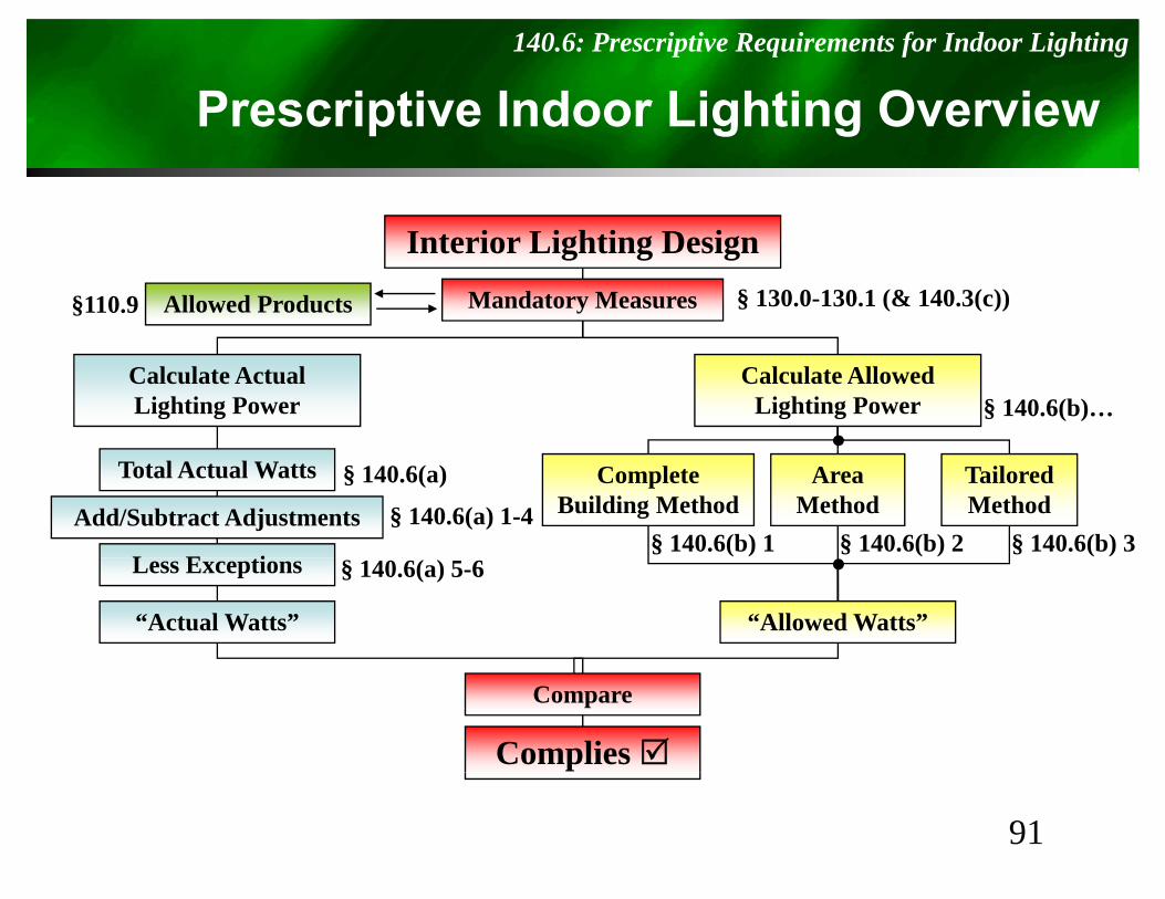
Prescriptive Indoor Lighting Overview140.6: Prescriptive Requirements for Indoor Lighting
p g g
I t i Li hti D iInterior Lighting DesignMandatory Measures § 130.0-130.1 (& 140.3(c))Allowed Products§110.9
Calculate AllowedLighting Power
Calculate ActualLighting Power § 140.6(b)…
CompleteBuilding Method
AreaMethod
TailoredMethod
Total Actual Watts
Add/Subtract Adjustments
L E ti
§ 140.6(a)
§ 140.6(a) 1-4§ 140.6(b) 1 § 140.6(b) 2 § 140.6(b) 3
Less Exceptions
“Actual Watts” “Allowed Watts”
§ 140.6(a) 5-6
Compare
Complies
91
Actual Lighting Power Density (LPD)146(a): Prescriptive Requirements for Indoor Lighting
g g y ( )
• Actual must be less than AllowedI l d P t d P t bl Li hti• Include Permanent and Portable Lighting– Exception: Up to 0.3 watts/ft2 (was 0.2) of
portable lighting for office areas does not needportable lighting for office areas does not need to be included in the calculation
• Calculate Allowed Indoor Lighting PowerCalculate Allowed Indoor Lighting Power with one of the following– Complete Buildingp g– Area Category– Tailored Method
92
Interlocked Lighting146(a)1: Prescriptive Requirements for Indoor Lighting
g g
• Allowed when two lighting systems used– If there are two, they must be interlocked
• For auditoriums, convention centers, conference rooms, multipurpose rooms, or theater
• Watts of the smaller interlocked lighting system can be excludedy
• Lighting systems must be interlocked with a nonprogrammable double throw switchnonprogrammable double throw switch
93
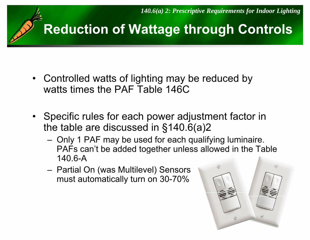
Reduction of Wattage through Controls140.6(a) 2: Prescriptive Requirements for Indoor Lighting
g g
• Controlled watts of lighting may be reduced by watts times the PAF Table 146Cwatts times the PAF Table 146C
• Specific rules for each power adjustment factor in p p jthe table are discussed in §140.6(a)2– Only 1 PAF may be used for each qualifying luminaire.
PAFs can’t be added together unless allowed in the TablePAFs can t be added together unless allowed in the Table 140.6-A
– Partial On (was Multilevel) Sensorsmust automatically turn on 30 70%must automatically turn on 30-70%
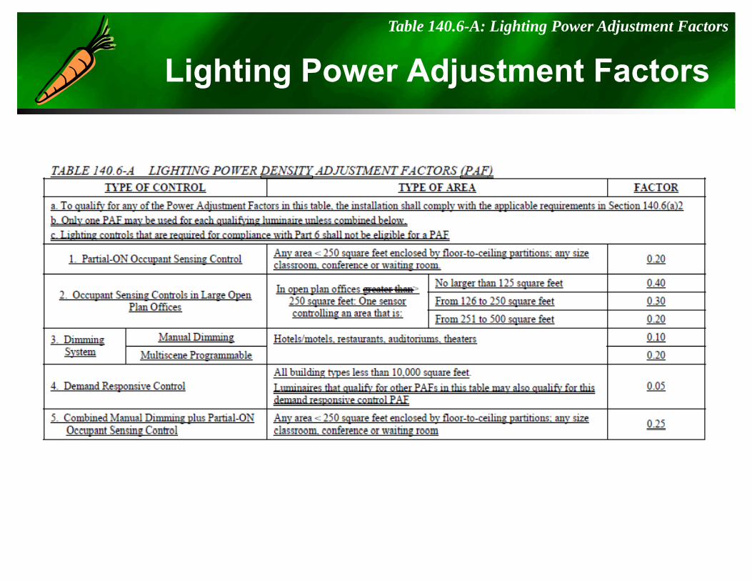
Lighting Power Adjustment FactorsTable 140.6-A: Lighting Power Adjustment Factors
g g j
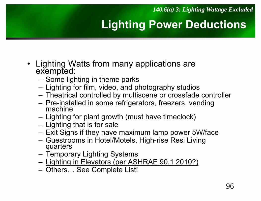
Lighting Power Deductions 140.6(a) 3: Lighting Wattage Excluded
g g
• Lighting Watts from many applications are exempted:– Some lighting in theme parks– Lighting for film, video, and photography studios– Theatrical controlled by multiscene or crossfade controller
P i t ll d i f i t f di– Pre-installed in some refrigerators, freezers, vending machine
– Lighting for plant growth (must have timeclock)Lighting that is for sale– Lighting that is for sale
– Exit Signs if they have maximum lamp power 5W/face– Guestrooms in Hotel/Motels, High-rise Resi Living
quartersqua te s– Temporary Lighting Systems– Lighting in Elevators (per ASHRAE 90.1 2010?)– Others… See Complete List!
96
p
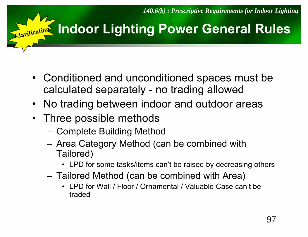
Indoor Lighting Power General Rules140.6(b) : Prescriptive Requirements for Indoor Lighting
g g
• Conditioned and unconditioned spaces must be calculated separately - no trading allowedcalculated separately - no trading allowed
• No trading between indoor and outdoor areas• Three possible methods• Three possible methods
– Complete Building Method– Area Category Method (can be combined with g y (
Tailored)• LPD for some tasks/items can’t be raised by decreasing others
Tailored Method (can be combined with Area)– Tailored Method (can be combined with Area)• LPD for Wall / Floor / Ornamental / Valuable Case can’t be
traded
97
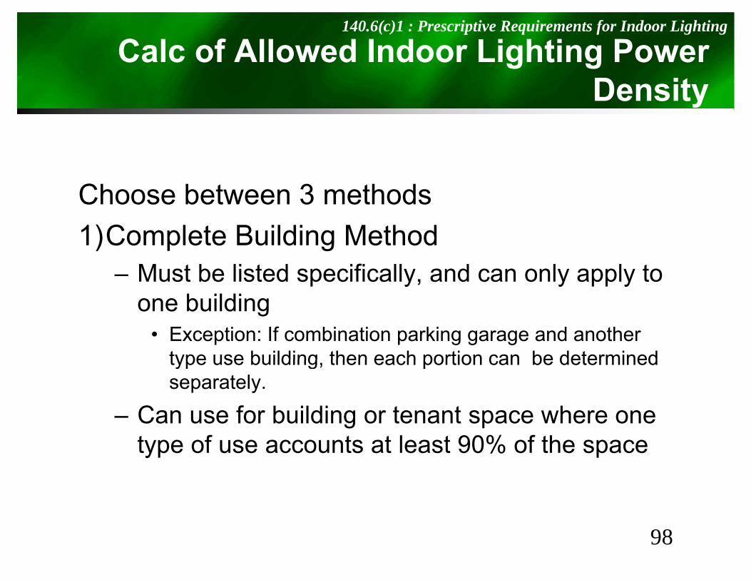
Calc of Allowed Indoor Lighting Power D it
140.6(c)1 : Prescriptive Requirements for Indoor Lighting
Density
Choose between 3 methods1)Complete Building Method
– Must be listed specifically, and can only apply to one building
• Exception: If combination parking garage and another type use building then each portion can be determinedtype use building, then each portion can be determined separately.
– Can use for building or tenant space where one type of use accounts at least 90% of the space
98
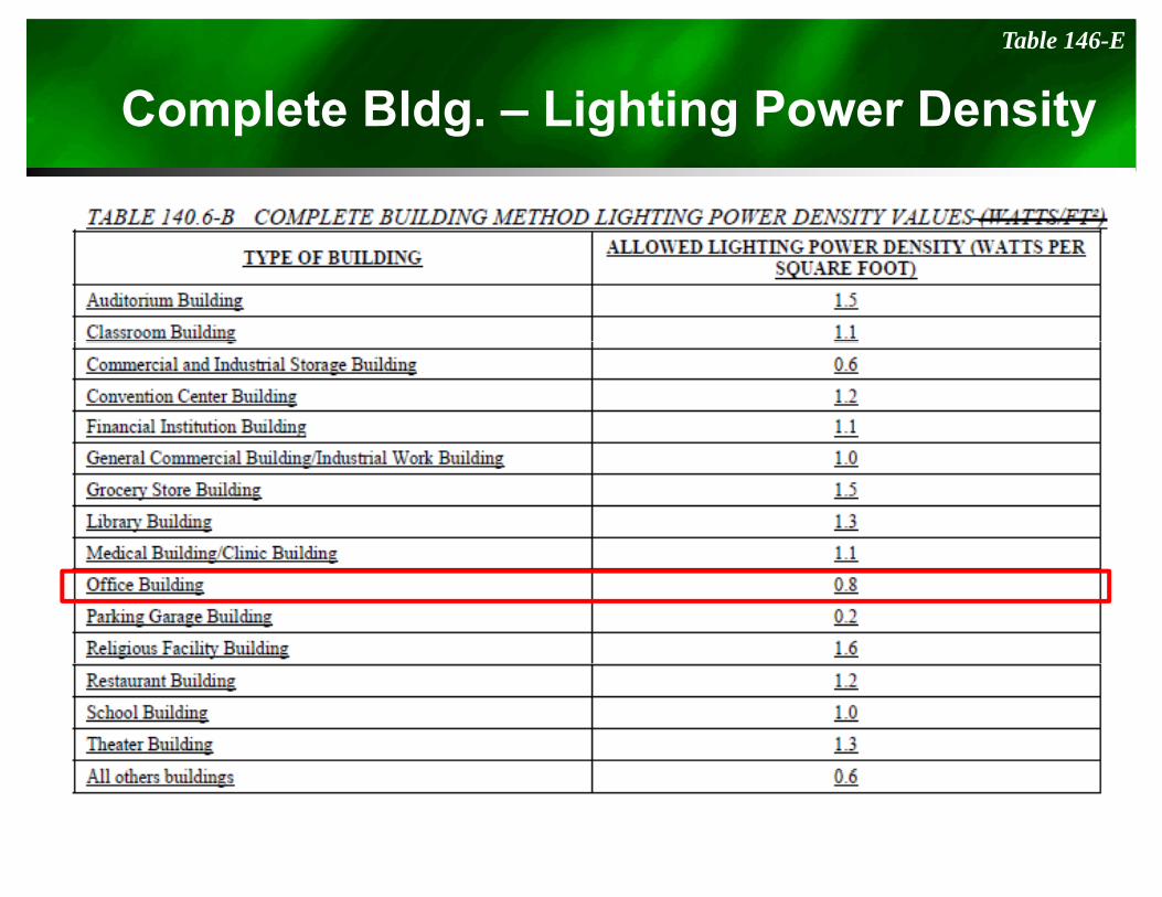
Complete Bldg. – Lighting Power DensityTable 146-E
p g g g y
Calculation of Allowed Indoor Lighting Power D it
140.6(c)2 : Prescriptive Requirements for Indoor Lighting
Density
Choose between 3 methods2) A C t M th d2) Area Category Method
• Total allowed lighting power is the sum of the allowed lighting powers for all individual areasallowed lighting powers for all individual areas
• Multi-tenant areas with an unknown tenant, use 0.6W/ft2 for lighting (Unleased Tenant Area)g g ( )
• Allowance in Table’s footnote for specialized tasks, ornamental, precision, accent, display, d ti id f i hit d h lkdecorative, video conferencing, white and chalk boards under specific conditions
100
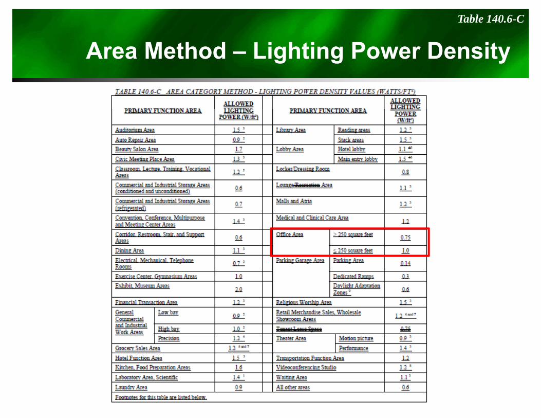
Area Method – Lighting Power DensityTable 140.6-C
g g y
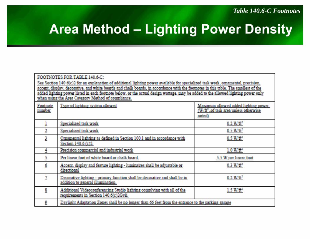
Area Method – Lighting Power DensityTable 140.6-C Footnotes
g g y
Calculation of Allowed Indoor Lighting Power D it
140.6(c)3 : Prescriptive Requirements for Indoor Lighting
Density
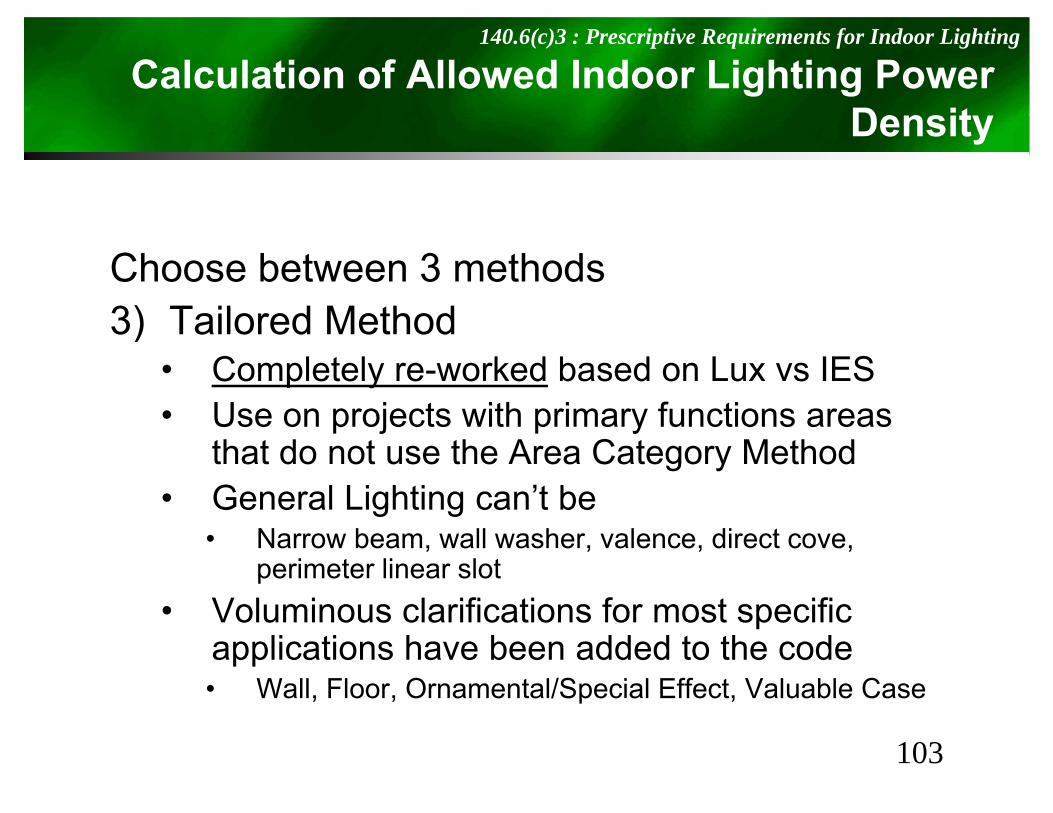
Choose between 3 methods3) T il d M th d3) Tailored Method
• Completely re-worked based on Lux vs IESU j t ith i f ti• Use on projects with primary functions areas that do not use the Area Category Method
• General Lighting can’t beGeneral Lighting can t be• Narrow beam, wall washer, valence, direct cove,
perimeter linear slotV l i l ifi ti f t ifi• Voluminous clarifications for most specific applications have been added to the code• Wall, Floor, Ornamental/Special Effect, Valuable Case, , p ,
103
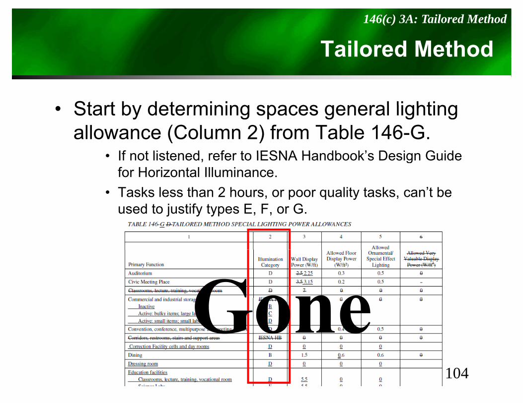
Tailored Method 146(c) 3A: Tailored Method
Start by determining spaces general lighting• Start by determining spaces general lighting allowance (Column 2) from Table 146-G.
If not listened refer to IESNA Handbook’s Design Guide• If not listened, refer to IESNA Handbook’s Design Guide for Horizontal Illuminance.
• Tasks less than 2 hours, or poor quality tasks, can’t be used to justify types E, F, or G.
104

Tailored Method – Lighting Power DensityTable 140.6-D
g g y
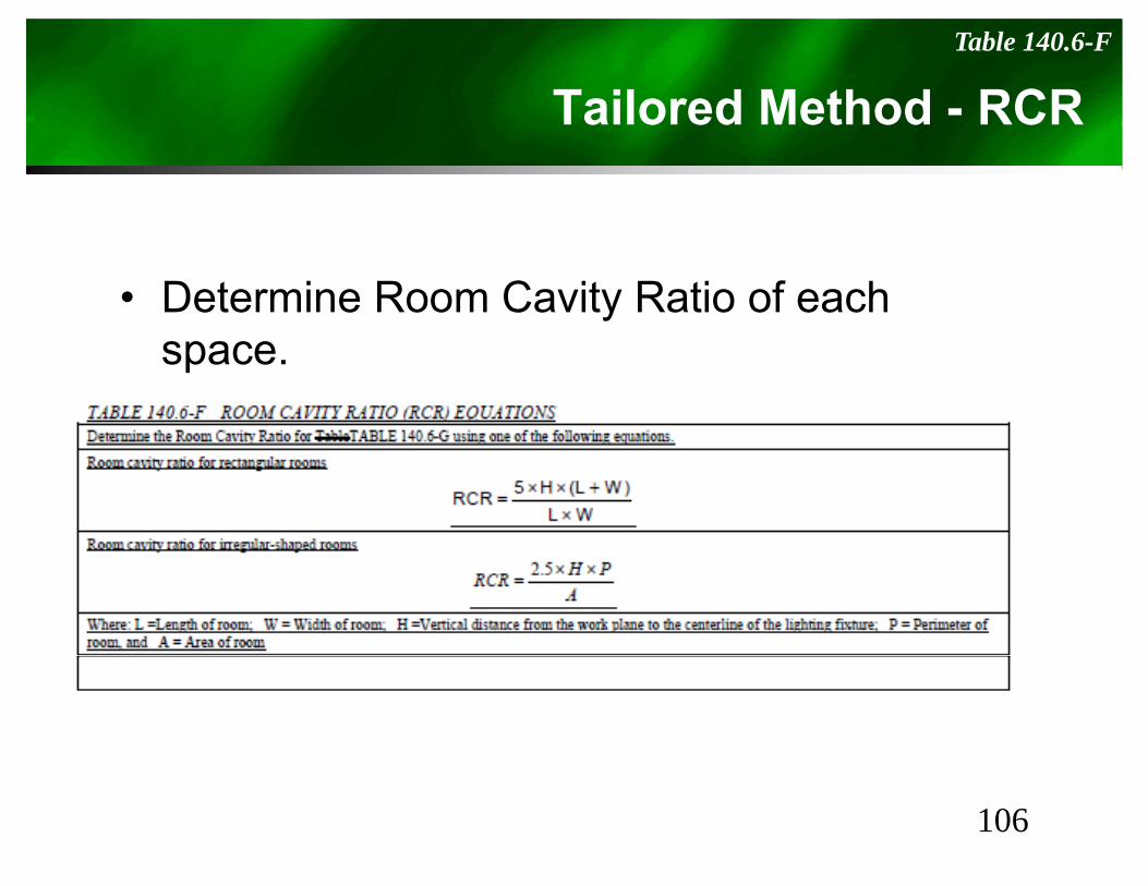
Tailored Method - RCRTable 140.6-F
• Determine Room Cavity Ratio of each space.
106
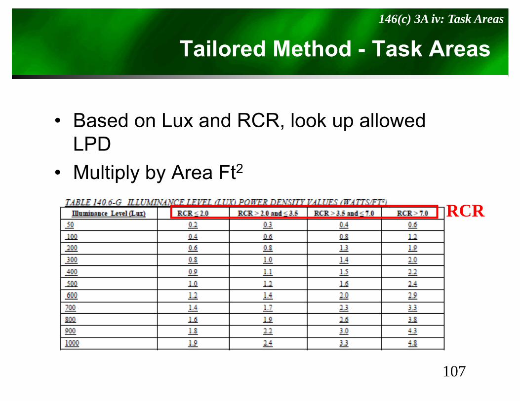
Tailored Method - Task Areas146(c) 3A iv: Task Areas
• Based on Lux and RCR, look up allowed LPD
• Multiply by Area Ft2
RCR
107

Tailored Method - “Use it or Lose it”Table 140.6-D: Additional Allowed Power
• For primary functions listed in Table 140 6-D thereFor primary functions listed in Table 140.6 D, there may be Additional Allowed Power.
• If these additional powers aren’t used, they’re lost.t ese add t o a po e s a e t used, t ey e ost
Ornamental/Special
Wall DisplaysFloor Displays
Use ItUse ItOr
Lose It!
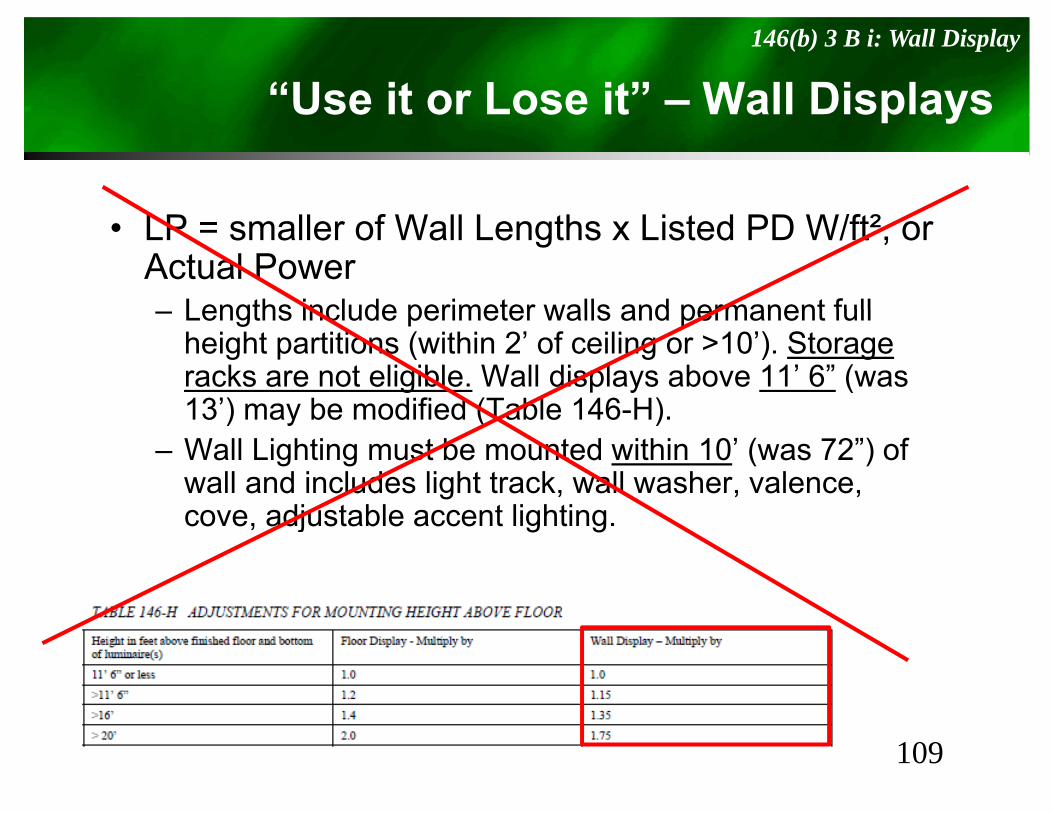
“Use it or Lose it” – Wall Displays146(b) 3 B i: Wall Display
p y
• LP = smaller of Wall Lengths x Listed PD W/ft², or Actual Power
Lengths include perimeter walls and permanent full– Lengths include perimeter walls and permanent full height partitions (within 2’ of ceiling or >10’). Storage racks are not eligible. Wall displays above 11’ 6” (was 13’) may be modified (Table 146 H)13 ) may be modified (Table 146-H).
– Wall Lighting must be mounted within 10’ (was 72”) of wall and includes light track, wall washer, valence,
dj bl li h icove, adjustable accent lighting.
109
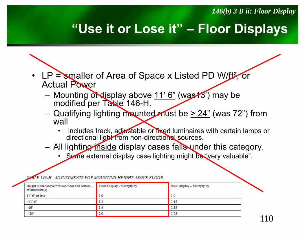
“Use it or Lose it” – Floor Displays146(b) 3 B ii: Floor Display
p y
• LP = smaller of Area of Space x Listed PD W/ft², or Actual Power– Mounting of display above 11’ 6” (was13’) may be
modified per Table 146-H. – Qualifying lighting mounted must be > 24” (was 72”) from
wall• includes track, adjustable or fixed luminaires with certain lamps or
directional light from non-directional sources.All lighting inside display cases falls under this category– All lighting inside display cases falls under this category.
• Some external display case lighting might be “very valuable”.
110
“Use it or Lose it” – Ornamental/Special146(b) 3 B iii: Ornamental/Special Effects
Sp
• LP = smaller of Area of Primary Function x Li t d PD W/ft² A t l PListed PD W/ft², or Actual Power– Ornamental luminaires include chandeliers,
l t d ld th d LEDsconces, lanterns, neon and cold cathode, LED, theatrical, moving lights, and light panels.Ornamental luminaires cannot be only light in– Ornamental luminaires cannot be only light in space.
111
“Use it or Lose it” – Very Valuable Display146(b) 3 B iv: Very Valuable Displays
y p y
• LP = smaller of:– Area of primary function x 1 W/ft² (no table used now)– Area of primary function x 1 W/ft (no table used now),– Case Area x 20 W/ft² (was 16), or– Actual Power
• Limited to Retail, Museums, and Religious worshipThis includes internal display case lighting (??? conflicts– This includes internal display case lighting (??? conflicts with Display) or highly directional external luminaires designed to illuminate inspection areas.C t i it lik j l i fi hi– Case contain items like jewelry, coins, fine china or crystal, precious stones, art and artifacts, or valuable collections.
112
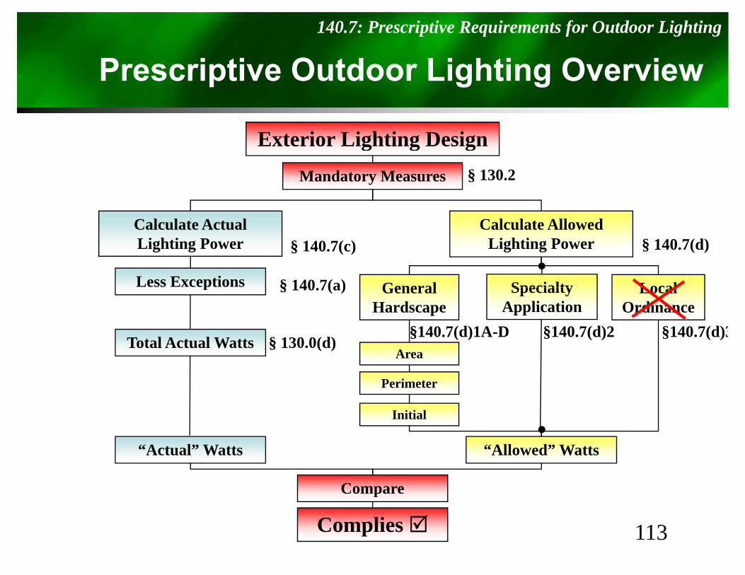
Prescriptive Outdoor Lighting Overview140.7: Prescriptive Requirements for Outdoor Lighting
p g g
Exterior Lighting Designg g gMandatory Measures
C AC A
§ 130.2
Calculate AllowedLighting Power
General Local
Calculate ActualLighting Power
Less Exceptions Specialty
§ 140.7(c) § 140.7(d)
§ 140 7(a)
§140.7(d)2
General Hardscape
LocalOrdinance
Total Actual Watts
p
§ 130.0(d)§140.7(d)1A-D
SpecialtyApplication
§140.7(d)3Area
§ 140.7(a)
Area
Perimeter
Initial
“Actual” Watts “Allowed” Watts
Compare
113
p
Complies
Outdoor Lighting140.7: Requirements for Outdoor Lighting
g g
• Compliance requires Actual LPD to be less than Allowed LPDthan Allowed LPD
• Long list of exceptions when 50% light falls within following applications– Temporary, FAA required, roadway, sports
fi ld hild ’ l d i d t i l itfields, children’s playgrounds, industrial site lighting, ATMs, public monuments, signs, pools and water features, tunnels, stairs, some ramps, , , , p ,landscape lighting, some historic lighting elements, etc...
114
Allowed Lighting Power140.7 (d): Requirements for Outdoor Lighting
g g
• Allowed Lighting is total of:– General Hardscape Lighting includes: parking
lots, roadways, sidewalks, walkways, bikeways, plazasplazas
– Specific Applications includes items from Table 147-B
• Building Entrance/Exit, Drive-up window, etc…
– Local Ordinance includes items fromTable 147-C Gone
115
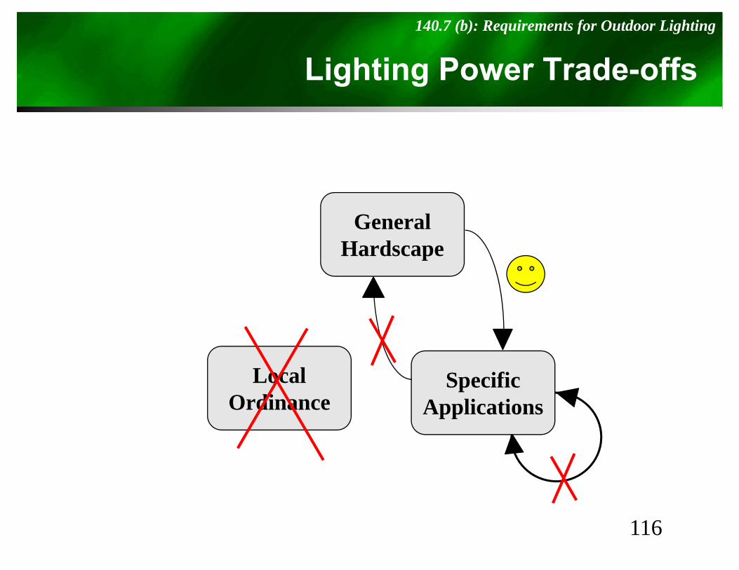
Lighting Power Trade-offs140.7 (b): Requirements for Outdoor Lighting
g g
G lGeneralHardscape
LocalOrdinance
SpecificApplications
116
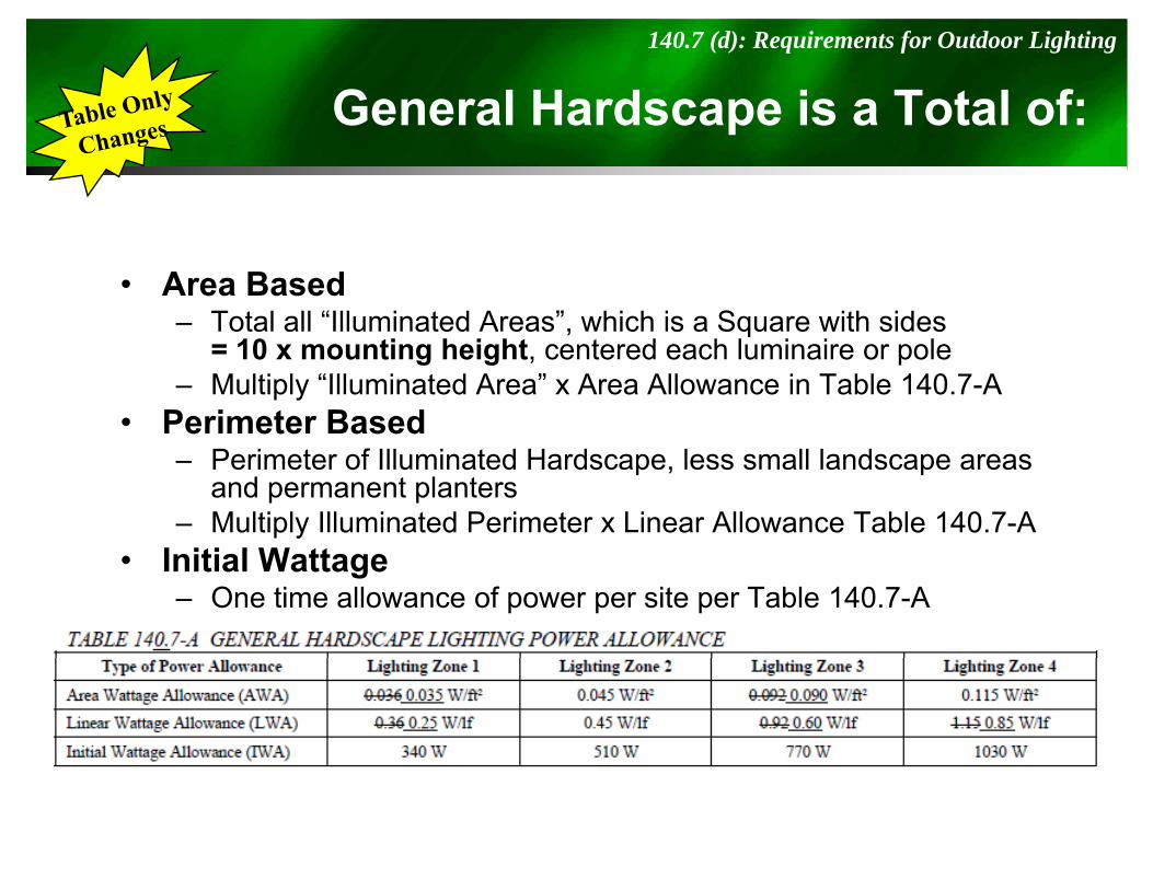
General Hardscape is a Total of:140.7 (d): Requirements for Outdoor Lighting
p
• Area Based– Total all “Illuminated Areas”, which is a Square with sides
10 i h i h d h l i i l= 10 x mounting height, centered each luminaire or pole– Multiply “Illuminated Area” x Area Allowance in Table 140.7-A
• Perimeter Based– Perimeter of Illuminated Hardscape, less small landscape areas
and permanent planters– Multiply Illuminated Perimeter x Linear Allowance Table 140.7-A
I iti l W tt• Initial Wattage– One time allowance of power per site per Table 140.7-A
§10-114: Outdoor Lighting Zones
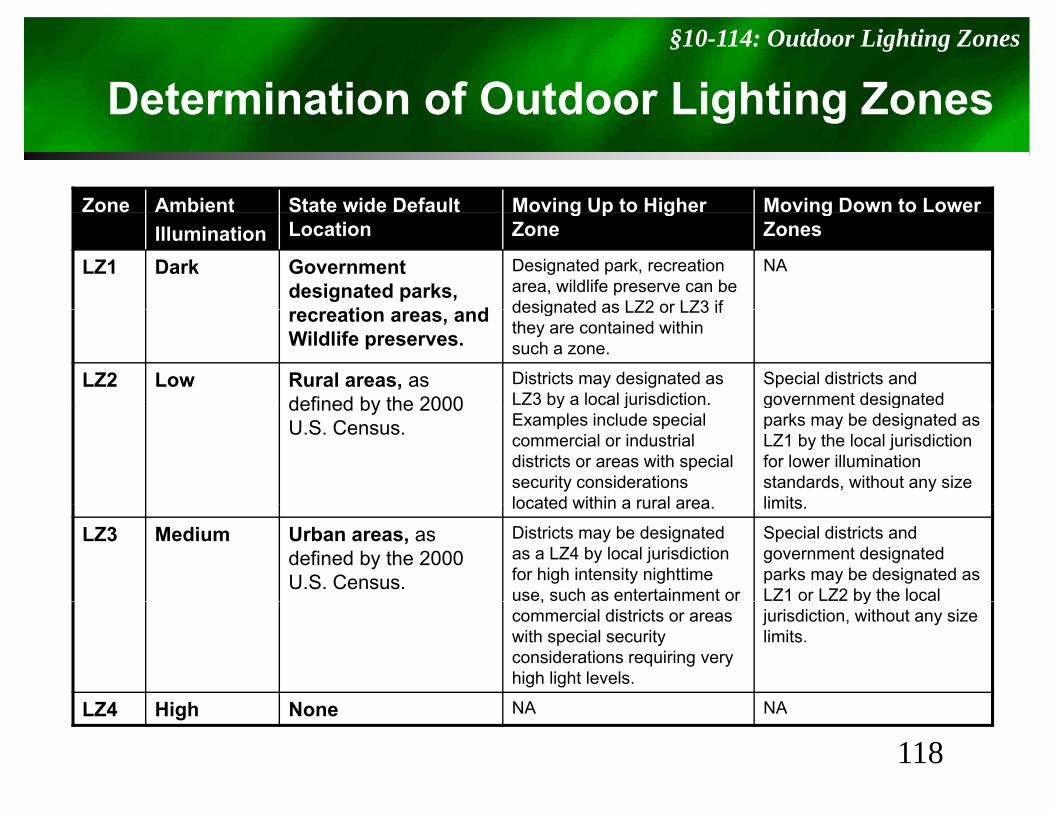
Determination of Outdoor Lighting Zones
Zone Ambient State wide Default Moving Up to Higher Moving Down to Lower
g g
o e b e tIllumination
State de e au tLocation
o g Up to g eZone
o g o to o eZones
LZ1 Dark Government designated parks,
ti d
Designated park, recreation area, wildlife preserve can be designated as LZ2 or LZ3 if
NA
recreation areas, and Wildlife preserves.
designated as LZ2 or LZ3 if they are contained within such a zone.
LZ2 Low Rural areas, as defined by the 2000
Districts may designated as LZ3 by a local jurisdiction.
Special districts and government designated defined by the 2000
U.S. Census.y j
Examples include special commercial or industrial districts or areas with special security considerations located within a rural area
g gparks may be designated as LZ1 by the local jurisdiction for lower illumination standards, without any size limitslocated within a rural area. limits.
LZ3 Medium Urban areas, as defined by the 2000 U.S. Census.
Districts may be designated as a LZ4 by local jurisdiction for high intensity nighttime use, such as entertainment or
Special districts and government designated parks may be designated as LZ1 or LZ2 by the local ,
commercial districts or areas with special security considerations requiring very high light levels.
yjurisdiction, without any size limits.
118LZ4 High None NA NA
§10-114: Outdoor Lighting Zones
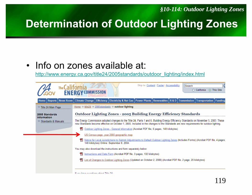
Determination of Outdoor Lighting Zonesg g
• Info on zones available at:http://www energy ca gov/title24/2005standards/outdoor lighting/index htmlhttp://www.energy.ca.gov/title24/2005standards/outdoor_lighting/index.html
119
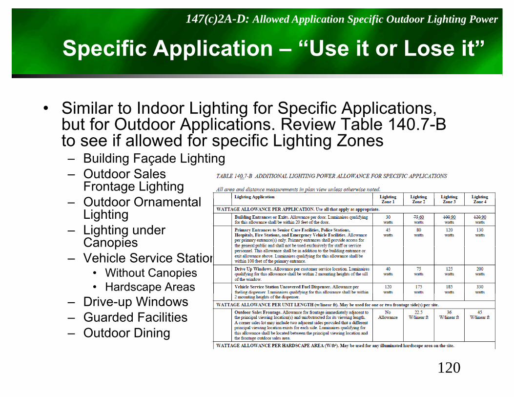
Specific Application – “Use it or Lose it”147(c)2A-D: Allowed Application Specific Outdoor Lighting Power
Sp pp
Si il t I d Li hti f S ifi A li ti• Similar to Indoor Lighting for Specific Applications, but for Outdoor Applications. Review Table 140.7-B to see if allowed for specific Lighting Zones– Building Façade Lighting– Outdoor Sales
Frontage LightingO td O t l– Outdoor Ornamental Lighting
– Lighting underCanopiesCanopies
– Vehicle Service Station• Without Canopies• Hardscape Areas
– Drive-up Windows– Guarded Facilities– Outdoor Dining
120
Indoor/Outdoor Signs148 : Requirements for Signs
g
• Indoor and Outdoor signs must comply with itheither:– Maximum Allowed Lighting Power– Alternate Lighting Source
121
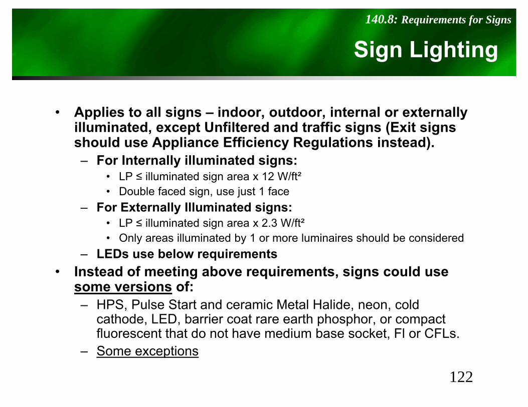
Sign Lighting140.8: Requirements for Signs
S g g g
• Applies to all signs – indoor, outdoor, internal or externally illuminated, except Unfiltered and traffic signs (Exit signs should use Appliance Efficiency Regulations instead). – For Internally illuminated signs:
• LP ≤ illuminated sign area x 12 W/ft²• Double faced sign, use just 1 face
F E t ll Ill i t d i– For Externally Illuminated signs:• LP ≤ illuminated sign area x 2.3 W/ft²• Only areas illuminated by 1 or more luminaires should be considered
LEDs use below requirements– LEDs use below requirements• Instead of meeting above requirements, signs could use
some versions of:HPS P l St t d i M t l H lid ld– HPS, Pulse Start and ceramic Metal Halide, neon, cold cathode, LED, barrier coat rare earth phosphor, or compact fluorescent that do not have medium base socket, Fl or CFLs.Some exceptions
122
– Some exceptions
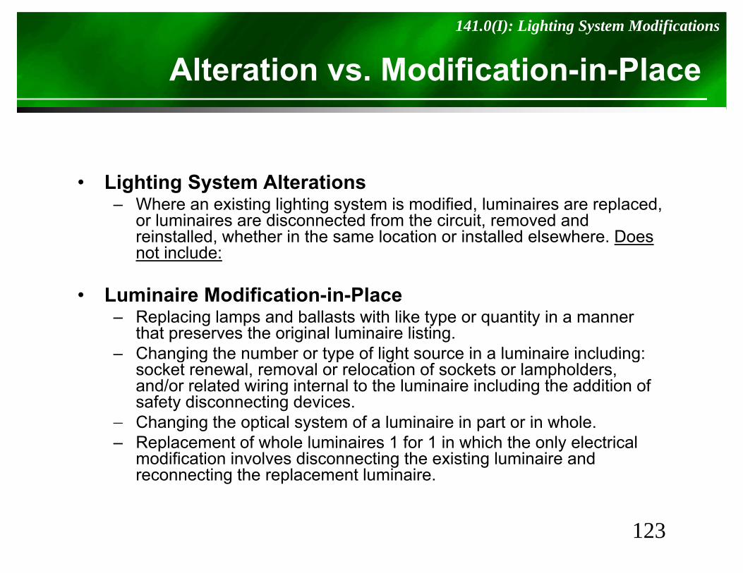
Alteration vs. Modification-in-Place 141.0(I): Lighting System Modifications
• Lighting System Alterations– Where an existing lighting system is modified, luminaires are replaced,
or luminaires are disconnected from the circuit removed andor luminaires are disconnected from the circuit, removed and reinstalled, whether in the same location or installed elsewhere. Does not include:
• Luminaire Modification-in-Place– Replacing lamps and ballasts with like type or quantity in a manner
that preserves the original luminaire listing. – Changing the number or type of light source in a luminaire including:Changing the number or type of light source in a luminaire including:
socket renewal, removal or relocation of sockets or lampholders, and/or related wiring internal to the luminaire including the addition of safety disconnecting devices.
– Changing the optical system of a luminaire in part or in wholeChanging the optical system of a luminaire in part or in whole.– Replacement of whole luminaires 1 for 1 in which the only electrical
modification involves disconnecting the existing luminaire and reconnecting the replacement luminaire.
123
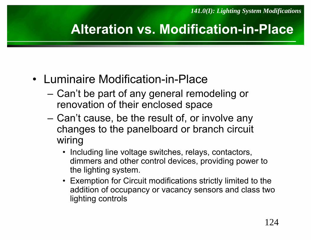
Alteration vs. Modification-in-Place 141.0(I): Lighting System Modifications
• Luminaire Modification-in-PlaceC ’t b t f l d li– Can’t be part of any general remodeling or renovation of their enclosed space
– Can’t cause be the result of or involve anyCan t cause, be the result of, or involve any changes to the panelboard or branch circuit wiring
• Including line voltage switches, relays, contactors, dimmers and other control devices, providing power to the lighting system.
f C f• Exemption for Circuit modifications strictly limited to the addition of occupancy or vacancy sensors and class two lighting controls
124
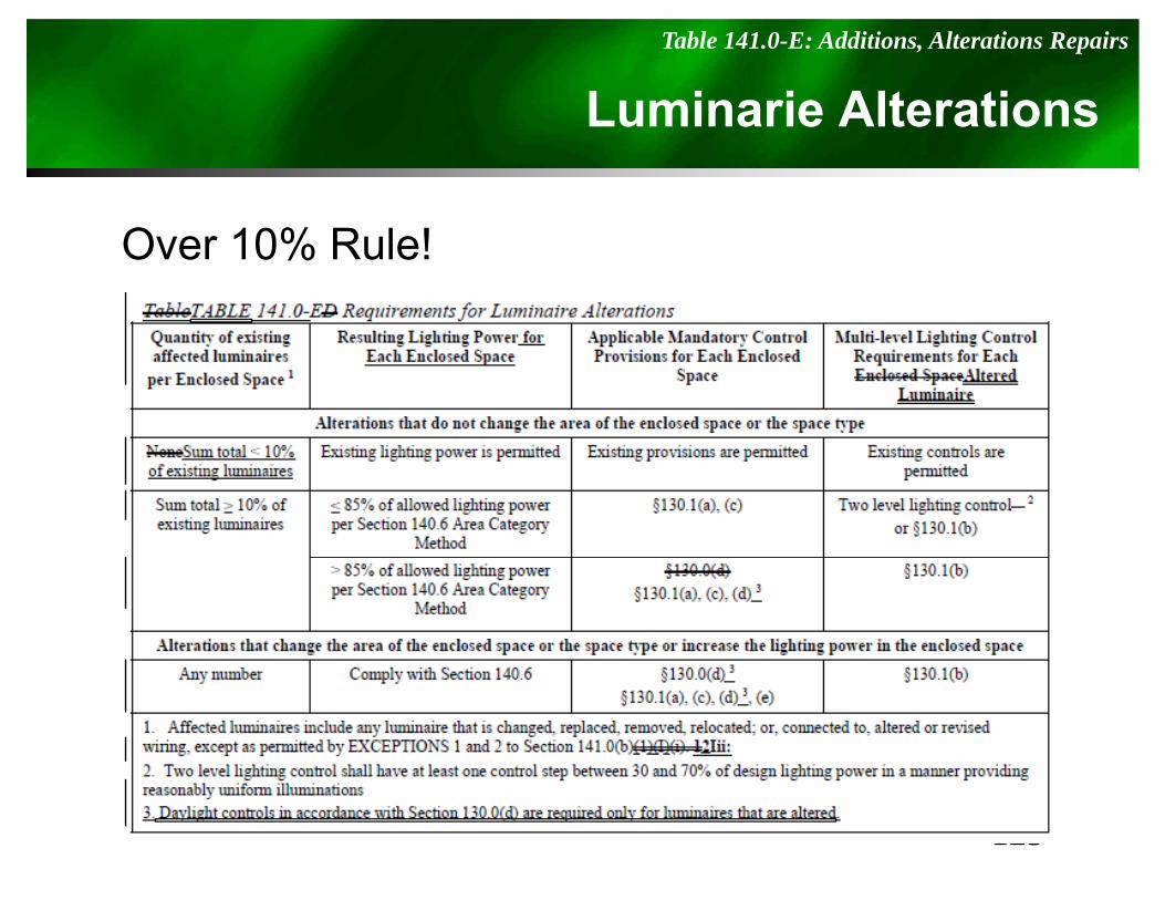
Luminarie AlterationsTable 141.0-E: Additions, Alterations Repairs
O 10% R l !Over 10% Rule!
125
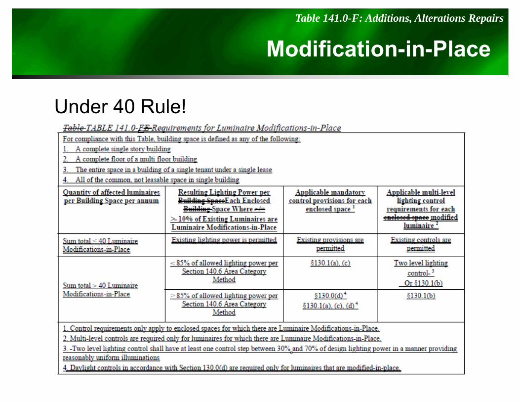
Modification-in-PlaceTable 141.0-F: Additions, Alterations Repairs
Under 40 Rule!Under 40 Rule!
126
Building Commissioning
120.8: Building Commissioning
Building Commissioning
• Building commissioning to be included in the design and construction of the building project to verify that the energy
t d t t th ’systems and components meet the owner’s or owner representative’s project requirements.
• Commissioning shall be performed in accordance with this ti b t i d l ith i j t fsection by trained personnel with experience on projects of
comparable size and complexity.• All building systems and components covered by Sections
110 0 120 0 130 0 and 140 0 shall be included in the110.0, 120.0, 130.0, and 140.0 shall be included in the scope of the commissioning requirements in this Section, excluding covered processes.
• For buildings less than 10 000 ft2 only the design review• For buildings less than 10,000 ft2, only the design review requirements in Section 120.8(d) and 120.8(e) shall be completed.
127
Summary of Commissioning Requirements
120.8(a): Building Commissioning
Summary of Commissioning Requirements
The following items shall be completed:1 Owner’s or owner representative’s project1. Owner s or owner representative s project
requirements;2. Basis of design;3. Design phase design review;4. Commissioning measures shown in the construction
documentsdocuments5. Commissioning plan;6. Functional performance testing;6. Functional performance testing;7. Documentation and training; and8. Commissioning report.
128
Owner’s Project Requirements (OPR)
120.8(b): Building Commissioning
Owner s Project Requirements (OPR)
The energy-related expectations and requirements of the building shall be documentedrequirements of the building shall be documented before the design phase of the project begins. This documentation shall include the following:
1 Energy efficiency goals;1. Energy efficiency goals;2. Ventilation requirements;3. Project program, including facility functions and j p g g y
hours of operation, and need for after hours operation; and
4. Equipment and systems expectations.q p y p
EXCEPTION: Buildings less than 10,000 ft2.
129
Basis of Design
120.8(c): Building Commissioning
Basis of Design
A written explanation of how the design of the building systems meets the OPR shall bebuilding systems meets the OPR shall be completed at the design phase of the building project, and updated as necessary during the design and construction phases The Basis ofdesign and construction phases. The Basis of Design document shall cover the following systems:
1. Heating, ventilation, air conditioning (HVAC) systems and controls;2. Indoor lighting system and controls; andg g y ;3. Water heating system.
EXCEPTION: Buildings less than 10,000 ft2.
130
Design Phase Design Review
120.8(d): Building Commissioning
Design Phase Design Review
1. Design Reviewer Requirements.For buildings less than 10,000 ft2, design phase design review may be completed by the design engineer. Buildings between 10,000 and 50,000 ft2 require completion of the g g g , , q pdesign review checklist by an engineer in-house to the design firm not associated with the building project. For buildings larger than 50,000 ft2 or for buildings with complex mechanical systems, an independent, third party review of these documents is required.2. Design Review.D i th h ti d i h f th b ildi j t th ’During the schematic design phase of the building project, the owner or owner’s representative, design team and design reviewer must meet to discuss the project scope, schedule and how the design reviewer will coordinate with the project team. The building owner or owner's representative shall include the Design Review Checklist compliance form in the Certificate of Compliance documentation (see Section 10-103).p p ( )3. Construction Documents Design Review.The Construction Documents Design Review compliance form lists the items that shall be checked by the design reviewer during the construction document review. The completed form shall be returned to the owner and design team for review and sign-off. Th b ildi ‘ t ti h ll i l d thi C t ti D tThe building owner or owner‘s representative shall include this Construction Documents Design Review compliance form in the Certificate of Compliance documentation (see Section 10-103).
131
Commissioning measures shown in the t ti d t
120.8(e): Building Commissioning
construction documents.
• Include commissioning measures or requirements in the construction documents (plans and specifications). C i i i i t h ld bCommissioning measures or requirements should be clear, detailed and complete to clarify the commissioning process. These requirements should include the list of systems and assemblies commissioned testing scopesystems and assemblies commissioned, testing scope, roles and responsibilities of contractors, requirements for meetings, management of issues, of the commissioning schedule, of operations and maintenance manualschedule, of operations and maintenance manual development and of training, of checklist and test form development, execution and documentation. Include, for information only, roles of non-contractor parties.
132
Commissioning Plan120.8(f): Building Commissioning
g
• Commissioning Plan. Prior to permit issuance a commissioning plan shall be completed to document how the project will be commissioned and shall be started during the design phase of the building projectand shall be started during the design phase of the building project. The Commissioning Plan shall include the following:
– 1. General project information;– 2. Commissioning goals;
3 Systems to be commissioned– 3. Systems to be commissioned.– 4. Plans to test systems and components shall include:
• A. An explanation of the original design intent;• B. Equipment and systems to be tested, including the extent of tests;• C. Functions to be tested;C. Functions to be tested;• D. Conditions under which the test shall be performed;• E. Measurable criteria for acceptable performance;• F. Commissioning team information; and• G. Commissioning process activities, schedules and responsibilities. Plans for the
completion of commissioning requirements listed in Sections 120 8(g) through 120 8(i) shallcompletion of commissioning requirements listed in Sections 120.8(g) through 120.8(i) shall be included.
• EXCEPTION for buildings less than 10,000 ft2 .
133

Functional Performance Testing120.8(g): Building Commissioning
g
• Functional performance tests shall demonstrate the correct installation and operation of eachcorrect installation and operation of each component, system and system-to-system interface in accordance with the Construction Documents. F ti l f t ti t h ll t iFunctional performance testing reports shall contain information addressing each of the building components tested, the testing methods utilized, p , g ,and include any readings and adjustments made. All Acceptance Requirements for Code Compliance shall be completed as part of this functionalshall be completed as part of this functional performance testing.
• EXCEPTION: Buildings less than 10,000 ft2.g ,
134
Documentation and Training120.8(h): Building Commissioning
g
1. Systems manual. Documentation of the operational aspects of the building shall be completed within the Systems Manual and delivered to the building owner or representative and facilities operator. The Systems Manual shall include the following:
A. Site information, including facility description, history and current requirements;B. Site contact information;C. Basic operations and maintenance, including general site operating procedures, basic troubleshooting, recommended
maintenance requirements, site events log;D. Major systems;E Sit i t i t d i t tE. Site equipment inventory and maintenance notes;F. A copy of all special inspection verifications required by the enforcing agency or this code; andG. Other resources and documentation.
2. Systems operations training. The training of the appropriate maintenance staff for each equipment type and/or system shall be documented in the commissioning report and shall include the following:
A. System/equipment overview (what it is, what it does and with what other systems and/or equipment itinterfaces)B. Review and demonstration of operation, servicing and preventive maintenanceC. Review of the information in the Systems ManualD. Review of the record drawings on the system/equipment
EXCEPTION to Section 120.8(h): Buildings less than 10,000 ft2 .
135
Permit, Certificate, …10-103: Construction Docuementation
, ,
All registration of nonresidential compliance d t ith HERS iddocuments with a HERS provider.
An electronic storage mechanism to archive all residential HERS and Nonresidential Compliance.
136
HVAC Occupant Sensors120.1(c)5: Mechanical Controls
p S
• HVAC systems are required to have D d C t l V til ti t i AiDemand Control Ventilation to insure Air Quality.– One way of meeting the requirement is CO2
Sensors.A th f <1 500 ft2 i O– Another way for spaces <1,500 ft2 is Occupancy Sensors which reduce airflow when space is unoccupiedunoccupied.
137
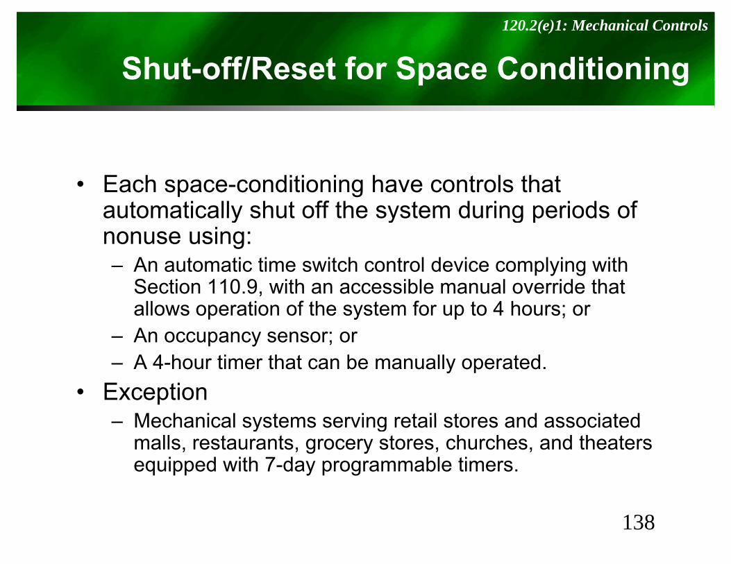
Shut-off/Reset for Space Conditioning120.2(e)1: Mechanical Controls
S Sp g
• Each space-conditioning have controls that automatically shut off the system during periods ofautomatically shut off the system during periods of nonuse using:– An automatic time switch control device complying with
S ti 110 9 ith ibl l id th tSection 110.9, with an accessible manual override that allows operation of the system for up to 4 hours; or
– An occupancy sensor; or– A 4-hour timer that can be manually operated.
• ExceptionMechanical systems serving retail stores and associated– Mechanical systems serving retail stores and associated malls, restaurants, grocery stores, churches, and theaters equipped with 7-day programmable timers.
138
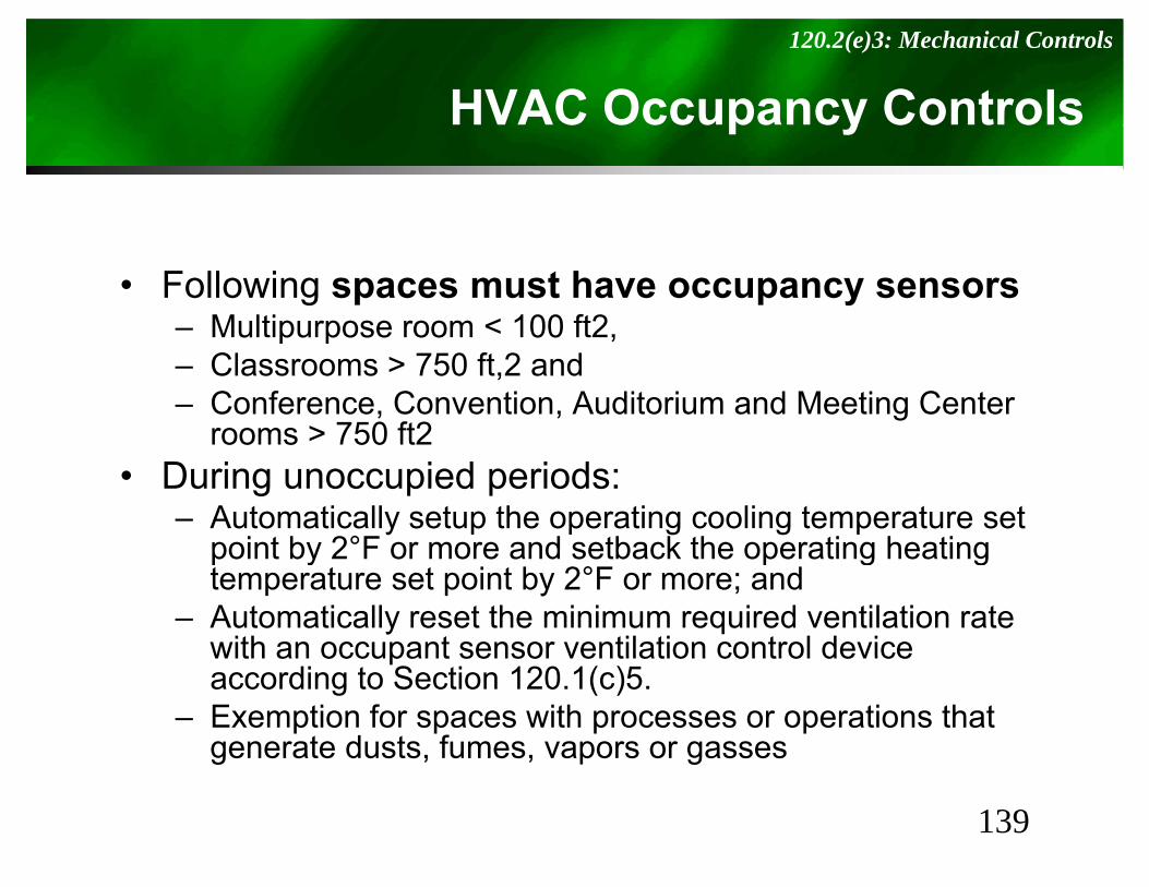
HVAC Occupancy Controls120.2(e)3: Mechanical Controls
p y
• Following spaces must have occupancy sensors– Multipurpose room < 100 ft2,u pu pose oo 00 ,– Classrooms > 750 ft,2 and– Conference, Convention, Auditorium and Meeting Center
rooms > 750 ft2rooms 750 ft2• During unoccupied periods:
– Automatically setup the operating cooling temperature set point by 2°F or more and setback the operating heatingpoint by 2 F or more and setback the operating heating temperature set point by 2°F or more; and
– Automatically reset the minimum required ventilation rate with an occupant sensor ventilation control devicewith an occupant sensor ventilation control device according to Section 120.1(c)5.
– Exemption for spaces with processes or operations that generate dusts, fumes, vapors or gasses g p g
139
R id ti l R i tResidential Requirements
Under T24 Commercial Rules, CEC dictates power requirements, but doesn’t care about the fixtures used.
Under T24 Resi Rules, CEC doesn’t limit power used, but wants High Efficacy FixturesEfficacy Fixtures.
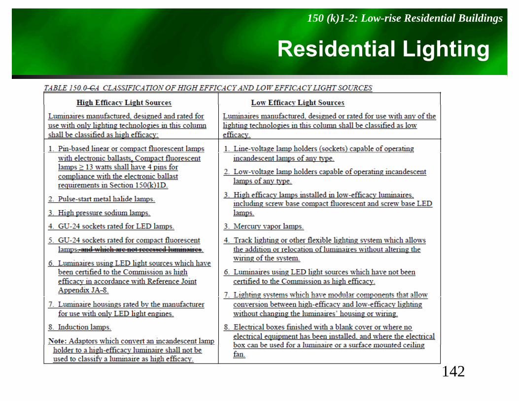
Residential Lighting150.0 (k)1-2: Low-rise Residential Buildings
g g
• Per Tables 150.0-A and 150.0–B, L i i ithLuminaires are either– High Efficiency– Low Efficiency
If i ’ h b id L i i i h b h Hi h d• If it’s a hybrid Luminaire with both High and Low Efficiency systems, each separately
li ith 150 0(k) i tcomplies with 150.0(k) requirements
141
Residential Lighting150 (k)1-2: Low-rise Residential Buildings
g g
142
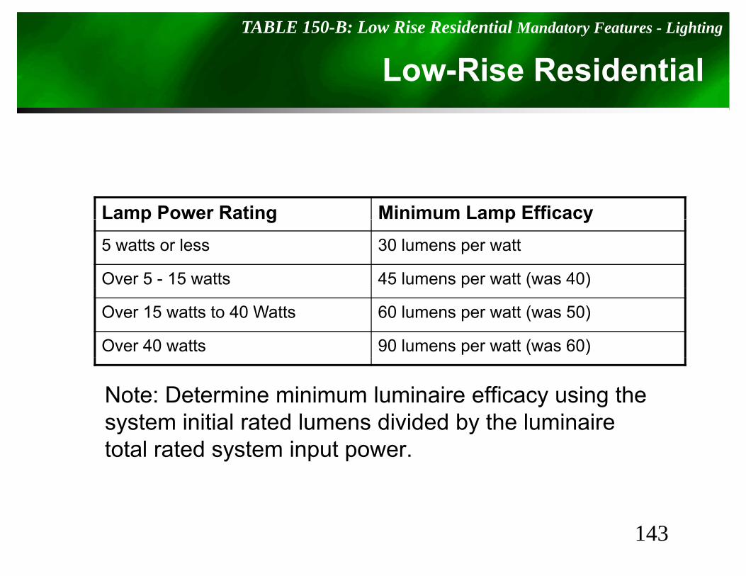
Low-Rise ResidentialTABLE 150-B: Low Rise Residential Mandatory Features - Lighting
Lamp Power Rating Minimum Lamp Efficacyp g p y5 watts or less 30 lumens per watt
Over 5 - 15 watts 45 lumens per watt (was 40)
Over 15 watts to 40 Watts 60 lumens per watt (was 50)
Over 40 watts 90 lumens per watt (was 60)
Note: Determine minimum luminaire efficacy using the system initial rated lumens divided by the luminairesystem initial rated lumens divided by the luminaire total rated system input power.
143
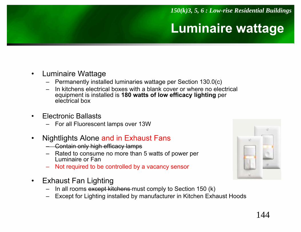
Luminaire wattage150(k)3, 5, 6 : Low-rise Residential Buildings
g
• Luminaire Wattage– Permanently installed luminaries wattage per Section 130.0(c)
In kitchens electrical boxes with a blank cover or where no electrical– In kitchens electrical boxes with a blank cover or where no electrical equipment is installed is 180 watts of low efficacy lighting per electrical box
• Electronic Ballasts• Electronic Ballasts– For all Fluorescent lamps over 13W
• Nightlights Alone and in Exhaust FansC i l hi h ffi l– Contain only high efficacy lamps
– Rated to consume no more than 5 watts of power perLuminaire or Fan
– Not required to be controlled by a vacancy sensor
• Exhaust Fan Lighting – In all rooms except kitchens must comply to Section 150 (k)– Except for Lighting installed by manufacturer in Kitchen Exhaust Hoods
144
Switching Devices & Controls150(k)7 : Low-rise Residential Buildings
S g &
• Switch High & Low Efficacy luminaires separately
• Switch Exhaust fans separately from lighting• Switch Exhaust fans separately from lighting– Exception Lighting integral to an exhaust fan may be on the same switch as the fan
provided the lighting can be switched OFF in accordance with the applicable i i i S ti 150(k)2 hil ll i th f t ti t t fprovisions in Section 150(k)2 while allowing the fan to continue to operate for an
extended period of time.
• Controls must be readily accessible and installed in accordance with the manufacturer’s instructions
• Cannot have controls that bypass any required dimmer or vacancy sensor
A E M t C t l S t d/ lti bl• An Energy Management Control System and/or multi-scene programmable controller may be used if it complies with Dimming or Vacancy Sensor requirements.
145
Lighting Specific to rooms150(k)8 : Low-rise Residential Buildings
g g Sp
• Kitchens: ≥ 50% of permanently installed lighting must be high efficacy (by Watts)lighting must be high efficacy (by Watts)
• Exemption for:50W for dwelling units ≤ 2 500 ft2 or50W for dwelling units ≤ 2,500 ft2, or100W for dwelling units > 2,500 ft2 if:
• Meet 150.0(k)2 and low efficacy All kitchen luminaires ( ) yare controlled by a vacancy sensor or dimmer, EMCS, or programmable control system, AND
• All permanently installed lights in garages, laundry rooms closets > 70 ft2 and utility rooms are high efficacyrooms, closets > 70 ft2, and utility rooms are high efficacy AND controlled by a vacancy sensor(Note bathrooms are not included in list).
146
Lighting Specific to rooms150(k)9-11 : Low-rise Residential Buildings
g g Sp
• Internal Cabinet Lighting: ≤ 20 W/ linear ft.Regardless of the number of shelves or the number of doors per cabinet section, the length of an illuminated cabinet shall be determined by:
O h i t l l th f ill i t d bi t– One horizontal length of illuminated cabinet; or– One vertical length, per illuminated cabinet section; or– No more than one vertical length per every 40 horizontal inches of illuminated cabinet.
• Bathrooms: Must have 1 High efficacy light, and all other should be high efficacy lighting unless it’s controlled by a vacancy sensor
• Garages, Laundry Rooms, Utility Rooms: Use high efficacy lighting and must be t ll d bcontrolled by a vacancy sensor
• Other rooms: High efficacy lighting or controlled by a dimmer or vacancy sensor– Closets < 70 ft2 exempted
Doesn’t include small detached storage buildings– Doesn t include small detached storage buildings
Low-Rise Resi – Other Requirements150 (k) 12, 15, 16: Other Residential Lighting Notes
q
• Luminaires recessed into ceilings:– Must be zero clearance insulation contact rated.– Must be certified as Air Tight (unless Exhaust fan housing),– Be sealed with gasket or caulk between housing and ceiling.– For recessed CFLs with ballasts to be High Efficacy, ballasts
t b tifi d t CEC § 110 9must be certified to CEC per § 110.9– Allow Ballast maintenance and replacement from below ceiling
without having to cut holes in ceiling.
• Parking lots and carports for 8 or more cars:– Must comply with §130, 132, 134, and 147.– Garages must comply with §130, 131, 134, and 146g p y § , , ,
• Luminaires in common areas in low-rise residential buildings with 4 or more units must be High Efficacy, unless controlled by a Occupancy Sensor
148by a Occupancy Sensor.
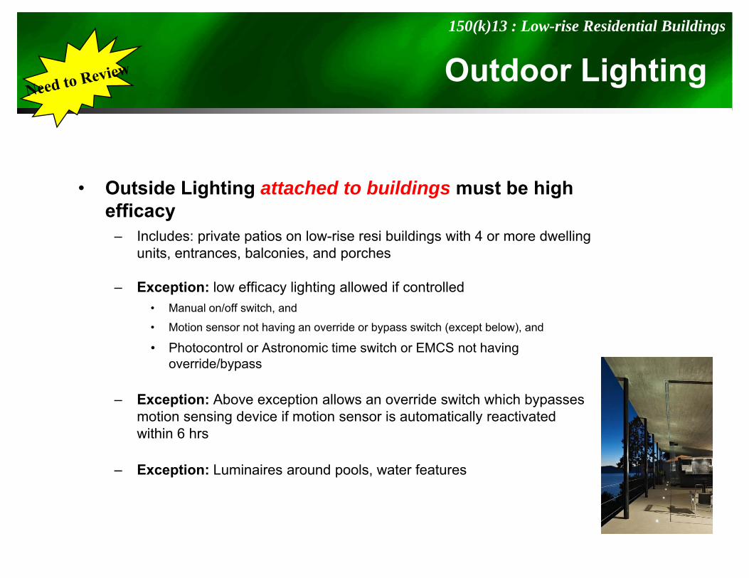
Outdoor Lighting150(k)13 : Low-rise Residential Buildings
g g
• Outside Lighting attached to buildings must be high efficacyy
– Includes: private patios on low-rise resi buildings with 4 or more dwelling units, entrances, balconies, and porches
– Exception: low efficacy lighting allowed if controlledException: low efficacy lighting allowed if controlled • Manual on/off switch, and
• Motion sensor not having an override or bypass switch (except below), and
• Photocontrol or Astronomic time switch or EMCS not having override/bypass
– Exception: Above exception allows an override switch which bypasses motion sensing device if motion sensor is automatically reactivated within 6 hrs
– Exception: Luminaires around pools, water features
Title 24 Resources
• http://www.energy.ca.gov/title24– Energy Efficiency Standardsgy y– Compliance Manual
• Hotline: 800-772-3300
150

Questions???Q
151

Watt Stopper Education SeriesWatt Stopper Education Series
Thank you
What are your questions?
For additional information:https://dl.dropbox.com/u/9929494/2013_Title24_r1.pdfwww.wattstopper.com 800 879-8585