ca telon application generator - ca support online telon application generator 5 1... · in writing...
TRANSCRIPT

Implementation Guide
r5.1
CA Telon® Application Generator

This documentation and any related computer software help programs (hereinafter referred to as the
"Documentation") are for your informational purposes only and are subject to change or withdrawal by CA at any time.
This Documentation may not be copied, transferred, reproduced, disclosed, modified or duplicated, in whole or in part,
without the prior written consent of CA. This Documentation is confidential and proprietary information of CA and may
not be used or disclosed by you except as may be permitted in a separate confidentiality agreement between you and
CA.
Notwithstanding the foregoing, if you are a licensed user of the software product(s) addressed in the Documentation,
you may print a reasonable number of copies of the Documentation for internal use by you and your employees in
connection with that software, provided that all CA copyright notices and legends are affixed to each reproduced copy.
The right to print copies of the Documentation is limited to the period during which the applicable license for such
software remains in full force and effect. Should the license terminate for any reason, it is your responsibility to certify
in writing to CA that all copies and partial copies of the Documentation have been returned to CA or destroyed.
TO THE EXTENT PERMITTED BY APPLICABLE LAW, CA PROVIDES THIS DOCUMENTATION "AS IS" WITHOUT
WARRANTY OF ANY KIND, INCLUDING WITHOUT LIMITATION, ANY IMPLIED WARRANTIES OF MERCHANTABILITY,
FITNESS FOR A PARTICULAR PURPOSE, OR NONINFRINGEMENT. IN NO EVENT WILL CA BE LIABLE TO THE END USER
OR ANY THIRD PARTY FOR ANY LOSS OR DAMAGE, DIRECT OR INDIRECT, FROM THE USE OF THIS DOCUMENTATION,
INCLUDING WITHOUT LIMITATION, LOST PROFITS, LOST INVESTMENT, BUSINESS INTERRUPTION, GOODWILL, OR
LOST DATA, EVEN IF CA IS EXPRESSLY ADVISED IN ADVANCE OF THE POSSIBILITY OF SUCH LOSS OR DAMAGE.
The use of any software product referenced in the Documentation is governed by the applicable license agreement and
is not modified in any way by the terms of this notice.
The manufacturer of this Documentation is CA.
Provided with "Restricted Rights." Use, duplication or disclosure by the United States Government is subject to the
restrictions set forth in FAR Sections 12.212, 52.227-14, and 52.227-19(c)(1) - (2) and DFARS Section
252.227-7014(b)(3), as applicable, or their successors.
Copyright © 2010 CA. All rights reserved. All trademarks, trade names, service marks, and logos referenced herein
belong to their respective companies.

CA Product References
This document references the following CA products:
■ CA Telon® Application Generator
■ CA Librarian®
■ CA InterTest®
■ CA Panvalet®
■ CA Realia®
■ CA Endevor Software Change Manager (CA Endevor SCM)
Contact CA
Contact Technical Support
For your convenience, CA provides one site where you can access the
information you need for your Home Office, Small Business, and Enterprise CA
products. At http://ca.com/support, you can access the following:
■ Online and telephone contact information for technical assistance and
customer services
■ Information about user communities and forums
■ Product and documentation downloads
■ CA Support policies and guidelines
■ Other helpful resources appropriate for your product
Provide Feedback
If you have comments or questions about CA product documentation, you can
send a message to [email protected].
If you would like to provide feedback about CA product documentation, complete
our short customer survey, which is also available on the CA Support website,
found at http://ca.com/docs.


Contents 5
Contents
Chapter 1: Introduction 9
Use CA Telon ........................................................................... 9
Manage Technical Considerations ...................................................... 10
Manage Users ...................................................................... 10 Coordination Structure .................................................................. 11
Responsibilities ..................................................................... 11
Distribute Tapes and Documentation ................................................... 12 Advantages ........................................................................ 13
Audience .......................................................................... 13
Chapter 2: Basic Procedures 15
Customization ......................................................................... 15 Design Facility Customization ............................................................ 16
Test the TDF ....................................................................... 17
Access the TDF Installation Menu ...................................................... 18 Customize Naming Conventions (Optional).............................................. 20
Customize the Program Format and Environment (Optional)............................... 24
Customize Security Environment (Optional) ............................................. 26 List Headers........................................................................ 32
Modify Installation Profile Defaults (Optional) ........................................... 33
Clean Up Work-In-Progress (WIP) Files .................................................... 34 List Programs for WIP Files ........................................................... 35
List Data Administration Records for WIP Files........................................... 35
List SQL Records for WIP Files ........................................................ 36 Generator Customization ................................................................ 37
Generator Overview ................................................................. 38
Copy PGMNAMES from PGMNAMED .................................................... 39 Customize Naming Conventions (Optional).............................................. 39
Setting Up Names ................................................................... 40
Customize User Edit Usage (Optional) .................................................. 48 Customize System Defaults (Optional) ................................................. 52
Customize Environment Defaults (Optional) ............................................. 66
Load/Build Customizable Macros Feature (Optional) ...................................... 81 Further Customization of Macro Libraries................................................... 85
Security ........................................................................... 86
Include Standard Copy Members ...................................................... 89 Naming Conventions ................................................................ 89
6 Implementation Guide
System Default Differences ........................................................... 90
Maintenance ....................................................................... 90 Implementation Tips .................................................................... 91
Terminate a Program Abnormally ......................................................... 91
Abnormal Termination Feature 1 ...................................................... 91 Parameter Descriptions .............................................................. 95
Abnormal Termination Feature 2 ...................................................... 99
Abnormal Termination Feature 3 .....................................................109
Chapter 3: Manage the CA Telon Environment 119
User-Defined Subroutines...............................................................120
TDF VSAM Data Set Maintenance ........................................................121
Reorganization and Clearing .........................................................122 Back Up TDF VSAM Data Sets ........................................................123
Verifying TDF VSAM Data Sets .......................................................124
Multiple TDF VSAM Data Sets ...........................................................125 Considerations.....................................................................126
Procedure .........................................................................126
Monitoring ........................................................................127 Maintain TDF Help Screens..............................................................127
Online Help Message Modifications....................................................128
Batch Help Message Update .........................................................130 TDF and Multiple Region Operation .......................................................132
Product and Project Set-Up Checklist .....................................................132
Checklist..........................................................................133
Chapter 4: Implementing CA Telon Online 135
IMS/DC Environment...................................................................135
Generate an IMS/DC System ........................................................136
Conversation Modes ................................................................136 Potential Errors that Occur in IMS/DC .................................................137
Structure Options .....................................................................138
Dynamic Program Structure .........................................................138 Static Program Structure ............................................................142
Dynamic Program Structure.............................................................147
Static Program Structure ...............................................................148 WORKSPA Processing ..................................................................149
Database Concepts .................................................................149
User Call..........................................................................150 Creation/Deletion ..................................................................150
Defining the WORKSPA .............................................................150

Contents 7
SPA/WORKSPA Relationship .........................................................151
Conversational Processing ..............................................................152 Transaction Code Specification .......................................................153
IMS/DC Conversational Implementation ...............................................154
SPA/WORKSPA Considerations .......................................................157 Starting/Terminating a CA Telon Conversation .............................................158
Non-conversational Processing ..........................................................159
Transaction Code Specification .......................................................160 IMS/DC Non-conversational Background...............................................161
IMS/DC Non-conversational Implementation ...........................................162
WORKSPA Considerations ...........................................................163 WORKSPA Size Calculation ..........................................................163
Non-conversational Processing without a WORKSPA Database ............................164
Appendix A: Implement Batch 169
Extract Files ..........................................................................169 IMS/VS Message Queue Support .........................................................169
IMS/VS Checkpoint/ Restart Support .....................................................170
GSAM Support ........................................................................172 Batch Subroutines .....................................................................174
Appendix B: Install Members 177
Cross-Reference Listing ................................................................177
Automated Documentation ..........................................................178 Installation Members...................................................................187
Format of Entries ..................................................................188
J*****L CA Telon Generate, Compile and Link JOB .....................................195 TL*****L CA Telon Generate, Compile, and Link PROCedure ............................210
Appendix C: Installation Defaults for Mainframe Targets 225
CICS Installation-Specific Information ....................................................226
Non-Procedural Statement Defaults ...................................................226 COPY/INCLUDE Member Names ......................................................230
Program Names ...................................................................230
CICS Control Names ................................................................231 General Implementation Considerations ...............................................231
IMS Installation-Specific Information .....................................................232
Installation Modifiable Parameters ....................................................232 Copy/Include Names ...............................................................233
COBOL Program Names .............................................................234
PLI Programs ......................................................................234

8 Implementation Guide
IMS Control Names.................................................................234
IMS Overrides on CA Telon Statements................................................235 Add New Edits .....................................................................236
Prepare an Application for Development ...............................................237
CA Telon Procedures................................................................238
Appendix D: Important Parameters 239
Print Parameters ......................................................................239
Parameters Passed to TELONTDF ........................................................241
Appendix E: Mainframe TDF Abends 243
Recommendations for Handling U901 Abends ..............................................244
Index 245

Chapter 1: Introduction 9
Chapter 1: Introduction
Now that CA Telon is installed at your site, it is important to have a CA Telon
coordinator onsite to manage the product's use and to ensure that training is
provided so that your site uses CA Telon most effectively.
For optimal performance, this guide describes basic information about defining
the production environment and customizing the CA Telon Design Facility (TDF),
and the CA Telon Application Generator. Guidelines are also provided for general
implementation tips and descriptions of the INSTALL data set members on the
CA Telon mainframe installation tape.
Note: Information on using the utilities is also provided.
We recommend having one or more people at your installation who are
responsible for coordinating all CA Telon-related activity. Every CA Telon
installation is different, so your DP shop must ultimately determine the best flow
of communication for your site. The suggestions made in this chapter are based
on the experiences of CA technical field personnel.
This chapter takes you through the need for coordination, a description of the CA
Telon coordinator role, and the advantages of having a CA Telon coordinator.
These ideas are by no means comprehensive, but seek to draw out the most
important issues for you to consider.
Again, there are no hard and fast rules on coordinating CA Telon activity at your
site, but it is important to think through these issues. Consult with your CA Telon
field technical representative about any questions you have concerning CA Telon
coordination or for specific guidelines in establishing CA Telon coordination at
your site.
This section contains the following topics:
Use CA Telon (see page 9)
Coordination Structure (see page 11)
Use CA Telon
CA Telon is a complex product to implement because it performs multiple tasks
and is flexible. Flexibility means that CA Telon is used differently in different
environments. Since CA Telon enables you to perform multiple tasks, it most
likely has an impact on a large number of users in a DP shop.

Use CA Telon
10 Implementation Guide
Manage Technical Considerations
CA Telon's flexibility means that large and small data processing shops use CA
Telon, and so no absolute rules of coordination can be made.
Some shops have multiple databases, multiple TDFs or multiple target
environments. These complexities plus differing shop sizes mean that CA Telon
is implemented differently in each environment.
However, certain concepts of coordination can be extracted from this diversity.
Some examples of technical considerations that the CA Telon coordinator could
address are:
■ Implementing new fixes, refreshes, and releases of CA Telon
■ Environment-specific problems (for example, a TSO development problem
or an OS/390 or z/OS target environment problem)
■ DBMS problems (for example, DB2 or VSAM problems)
■ Language problems (for example, a PL/I problem or a Custom Code problem
in COBOL)
■ Interface problems
A CA Telon coordinator can help manage technical issues. If a person has a
problem or question, they can contact the CA Telon coordinator and find out
where to go to fix the problem or answer the question. Managing fixes,
refreshes, and releases of CA Telon is also an important coordination process.
Manage Users
The multiple tasks that CA Telon performs usually means that there are multiple
users. Multiple users means that there is a need for communication.
Some companies have CA Telon users located in different sites. Often several
departments or sub-groups within departments are involved.
Some companies have all CA Telon users located in the same building. But even
close proximity does not diminish the need for coordinating information.
Some examples of user issues that the CA Telon coordinator could address are:
■ User training
■ Documentation distribution
■ User authorization
■ Communication between users
■ Problem determination

Coordination Structure
Chapter 1: Introduction 11
A CA Telon coordinator can help manage user issues. Communication is
enhanced by a central coordination point. Although the coordinator might not
know the answer, that person should know where to get the answer.
Coordination Structure
The CA Telon coordinator can be a team of people, one full-time person, or one
or more part-time people. Larger and more complex environments need more
coordination than smaller, simpler environments.
The CA Telon coordinator acts as a facilitator. The emphasis is on the operational
aspects of the CA Telon environment. The CA Telon coordinator does not need
specific product expertise, but needs to know the structure of your company.
Responsibilities
The responsibilities of a CA Telon coordinator vary significantly from one
company to another. However, this topic shows responsibilities that are often
given to the CA Telon coordinator. Analyze those given here to determine what
would be best suited for a CA Telon coordinator at your site.
Coordinating training
The CA Telon coordinator often guides the training process including:
■ Who receives training
■ Scheduling training sessions
■ Facilities to use for training
■ Correspondence with CA on training
■ Notification of people involved in training
■ Distribute training material (for example, pre-training exercise)
Facilitating adherence to in-house standards
The CA Telon coordinator needs to be well-acquainted with company and
departmental standards. This could include things such as signature
authorization, key people to notify, use of forms, diskette distribution,
authorization of new users, and security authorization.

Coordination Structure
12 Implementation Guide
Distribute Tapes and Documentation
An important coordination function is the distribution of product tapes and
documentation. CA sends tapes or documentation to a specified person in the
company, and this person makes sure that the information gets passed on to the
appropriate person or department.
Communicating with CA
As discussed earlier, CA has a contact person at a company for CA Telon-related
information. This could be for an alpha or beta agreement or a contact point for
resolving customer questions or problems.
The coordinator can also serve as a provider of enhancement requests. This
information is vital for strategic planning of future CA Telon releases.
Communicating within the team
One person or a group of people perform this centralized role of coordinating CA
Telon activity on a site. Without a coordinator, people may get isolated or
information may not get distributed. CA Telon can impact many groups within an
organization, so some sort of coordination is important.
Participating in user groups
The CA Telon coordinator participates in local CA Telon user groups or attends
the International User's Conference. This keeps people aware of the latest
enhancements to the product or insights from other users.
Guiding the implementation process
A technically trained coordinator can help guide the implementation process.
Perhaps there are backup procedures to verify, or checkpoints for achieving
implementation goals.

Coordination Structure
Chapter 1: Introduction 13
Advantages
There are many advantages to designating a person or team as CA Telon
coordinator at your site including:
■ Improving communication lines between many people and departments.
Isolationism can develop without proper communication channels. The
larger the environment, the more the CA Telon coordination function is
needed, though some coordination is necessary for all shop sizes.
■ Providing centralization and visibility by providing a contact point for
CA Telon-related activity. This helps a company both interdepartmentally
and intradepartmentally and also helps CA. Some coordination is necessary
for a large product like CA Telon, so it makes sense to have a visible
coordinator.
■ Enhancing efficiency by the appropriate time. Incorrect, missing, or late
information causes problems leading to inefficiency. Lack of coordination
wastes valuable time. A good coordinator enhances efficiency in the entire
environment because the information flow is better and less time is wasted.
■ Promoting order and unity onsite. People will know where to go to get
pertinent information. The individual members will feel like part of a team.
Audience
This guide is for users responsible for implementing CA Telon for production in
the mainframe or CA Telon PWS environment.


Chapter 2: Basic Procedures 15
Chapter 2: Basic Procedures
There is an indistinct line between installation and implementation. Installation
flows into implementation. However, the basic distinction made in CA Telon
documentation is that installation is directed toward unloading the product from
the tape and setting up the Training environment, whereas implementation
means setting up the production environment.
Since some companies incorporate implementation procedures during
installation, you should be familiar with the procedures discussed in CA Telon
(for the mainframe).
This chapter describes some of the basic procedures of implementation. Many of
the components and procedures described in this chapter were probably at your
site during the installation of the product. Therefore some procedures and
components require verifications rather than initial setup.
This section contains the following topics:
Customization (see page 15)
Design Facility Customization (see page 16)
Clean Up Work-In-Progress (WIP) Files (see page 34)
Generator Customization (see page 37)
Further Customization of Macro Libraries (see page 85)
Implementation Tips (see page 91)
Terminate a Program Abnormally (see page 91)
Customization
As part of the CA Telon installation process, a site may tailor CA Telon to suit
in-house standards and conventions. This tailoring is done against each of the
following CA Telon components, which are each addressed in more detail next:
■ CA Telon Design Facility (TDF)
■ CA Telon Application Generator
This chapter also provides:
■ A description of how to customize mainframe and PWS environment defaults
■ Information about how to define program abnormal termination parameters
■ Product and project setup checklists for you to use in your implementation
Design Facility Customization
16 Implementation Guide
Design Facility Customization
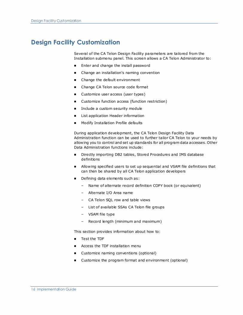
Several of the CA Telon Design Facility parameters are tailored from the
Installation submenu panel. This screen allows a CA Telon Administrator to:
■ Enter and change the install password
■ Change an installation's naming convention
■ Change the default environment
■ Change CA Telon source code format
■ Customize user access (user types)
■ Customize function access (function restriction)
■ Include a custom security module
■ List application Header information
■ Modify Installation Profile defaults
During application development, the CA Telon Design Facility Data
Administration function can be used to further tailor CA Telon to your needs by
allowing you to control and set up standards for all program data accesses. Other
Data Administration functions include:
■ Directly importing DB2 tables, Stored Procedures and IMS database
definitions
■ Allowing specified users to set up sequential and VSAM file definitions that
can then be shared by all CA Telon application developers
■ Defining data elements such as:
– Name of alternate record definition COPY book (or equivalent)
– Alternate I/O Area name
– CA Telon SQL row and table views
– List of available SSAs CA Telon file groups
– VSAM file type
– Record length (minimum and maximum)
This section provides information about how to:
■ Test the TDF
■ Access the TDF installation menu
■ Customize naming conventions (optional)
■ Customize the program format and environment (optional)

Design Facility Customization
Chapter 2: Basic Procedures 17
■ Customize the security environment (optional)
■ List headers
■ Modify information profile defaults (optional)
Test the TDF
Test the TDF installation by executing one of the following, depending on your
installation:
Environment Action
Mainframe TSO Execute the TSO CLIST @TDF
Mainframe CICS Execute CICS transaction TDF
PWS Access the CA Telon Design Facility
from the Telon menu tool bar.
Installation-specific considerations
■ For DB2 installations: Before you test the TDF, you must create and
import the Training DB2 tables. See the Installation guide for more
information.
■ For COBOL II installations: Set the COBOL II parameter LIBKEEP to YES
(LIBKEEP = YES) to maximize performance of the online TDF.
Mainframe CICS only
You should have already modified your CICS startup JCL to include DD
statements for the training files to be created as described in the Installation
guide. If you are running the TDF under CICS, you must either make sure the
statements are commented out or first perform the step described in the
Installation guide. If you fail to do so, you are not able to bring up your CICS
region. Instead, you receive a JCL error.
For CICS TDF installations, you must have performed your CICS modifica tions
prior to this step.

Design Facility Customization
18 Implementation Guide
Checking TDF operation
After allocating several files, the TDF displays the TDF Main Menu. To test the
TDF to be sure it operates as documented, see the Design Facility Reference
guide.
If the TDF does not operate as documented, check all job completion messages
and any custom modifications you have made to any JCL or command file to
make sure that all jobs have completed successfully and that you have not
introduced any errors.
Access the TDF Installation Menu
To execute the remaining steps in TDF initialization, you must first access the
TDF Installation menu.
When the TDF Main Menu is displayed, enter INSTALL in the COMMAND field.
The TDF displays this screen:
TDF INSTALLATION MENU *************** ***************************************** COMMAND ==>___________________________________________________________________ FUNCTION: __ UP-UPDATE PU-PURGE LI-LIST ITEM __ IP-INSTALLATION PROFILE US-USERS PW-PASSWORD RE-RESTRICT HD-HEADERS WF-TDF WIP WD-TDD WIP WX-TDX WIP PC-RESTRICT PWS DESKTOP SECURITY PASSWORD ENTER VALUE FOR SPECIFIC ITEM TO BE PROCESSED: 1. INSTALL 2 4 (HEADER AND ID LENGTHS) 4 0 (APPLID REQ/OPTIONAL AND ITS LENGTH) Y TSO___ (FORMATTING - COMPRESSION AND ENVIRONMENT) _ (U/I) (TELON DATE FORMAT - U.S./INTERNATIONAL) ________ (INSTALLATION SECURITY MODULE NAME) ________________________________________ (TDF IDENTIFICATION) 2. USER ________ (USER ID) _ (C-CONTROLLER P-PROGRAMMER A-ANALYST) 3. PASSWORD (NEW PASSWORD) (SAME NEW PASSWORD TO MINIMIZE KEYING ERRORS) 4. RESTRICT _ (C-CONTROLLER P-PROGRAMMER A-ANALYST)
To exit this screen without performing any action, enter CANCEL in the
COMMAND field.

Design Facility Customization
Chapter 2: Basic Procedures 19
From the TDF Installation menu you can:
■ Enter and change the install password
■ Change naming conventions
■ Change the default environment
■ Change CA Telon source code format
■ Provide TDF identification
■ Customize user access
■ Customize function access
■ Include a custom security module
■ List header information
■ Modify installation Profile defaults
Install password
To make changes from the TDF Installation menu, you must first enter:
■ UP in the FUNCTION field
■ IP in the ITEM field
■ The current password in the PASSWORD field that appears in the top half of
the screen
The PASSWORD fields are non-display fields. The TDF is delivered with the Install
password CSIMK. If you enter an incorrect password, the TDF displays the
message INCORRECT PASSWORD and allows you to re-enter the password.
Once you successfully enter the password, you can change it by entering:
■ UP in the FUNCTION field
■ PW in the ITEM field
You must enter the new password twice in the PASSWORD field in the bottom
half of the screen to verify it. The new password must be 5 characters long. To
enter a shorter password, enter spaces at the end so that the total of characters
entered is five. If the second entry you make in the PASSWORD field matches the
first, the update is successful, and the TDF displays PASSWORD CHANGED AND
PROFILE SAVED. If they are not identical, the TDF displays NEW PASSWORD
FIELDS DO NOT MATCH and does not update the password.
Note: If you change the password and forget your new password, call Customer
Support.

Design Facility Customization
20 Implementation Guide
Customize Naming Conventions (Optional)
The naming convention customization described here is optional. If you decide to
keep the default naming conventions, see Customize the Program Format and
Environment (Optional) (see page 24)
TDF program design information and CA Telon generated programs depend on
two items to generate names: header and ID. You can also use an optional
APPLID to identify application groups. By default, header is two characters long
and ID is four characters long. As delivered, the header and ID work together to
make program names.
Delivered header and ID program names
In the next table, hh is the two-character header and nnnn is the four-character
ID. arrange='1 2 3 3 / 1 2 4 5'.
Target Program control block Generated name
COBOL PL/I
IMS/DC TSO Program hhTMnnnn hhTnnnn
IMS Dynamic Program .hhIMnnnn hhInnnn
IMS Driver Program hhIMnnn hhMnnnn
.IMS Alias hhXMnnnn hhXnnnn
IMS Static Link Program hhSMnnnn hhSnnnn
BATCH hhBPnnnn hhBnnnn
IMS PSB hhIMnnnn hhInnnn
DIF/DOF hhDnnnn hhDnnnn
MID hhInnnn hhInnnn
MOD hhOnnnn hhOnnnn
CICS CICS hhCPnnnn hhPnnnn
Non-terminal hhNPnnnn BNnnnnhh
BMS Control Block hhZnnnn hhZnnnn
CICS Client Client program hhCCnnnn —
Server program hhnnnn —
BATCH Batch program hhBPnnnn hhBnnnn
STORED Stored Procedure Program hhSPnnnn hh2nnnn

Design Facility Customization
Chapter 2: Basic Procedures 21
Changing the header and ID
You can change the length of the header and ID on the TDF Installation menu as
long as their combined length does not exceed six characters. However, before
making any changes to header and ID size, discuss your plans with your CA
Telon technical representative or call Customer Support. All load modules,
control blocks, and mapping names are also generated by these items. For
example:
■ The code must reflect the same header and ID length you supply here
■ CA Telon training members are impacted by any modification of header and
ID lengths, as described in the Installation guide or in the appropriate CA
Telon target documentation
To change the header and ID lengths on the TDF Installation menu, enter the
lengths on the first line of the INSTALL field. The header and ID lengths are
highlighted in this example:
TDF INSTALLATION MENU *************** *****************************************
COMMAND ==>___________________________________________________________________
FUNCTION: __ UP-UPDATE PU-PURGE LI-LIST
ITEM __ IP-INSTALLATION PROFILE US-USERS PW-PASSWORD RE-RESTRICT
HD-HEADERS WF-TDF WIP WD-TDD WIP WX-TDX WIP
PC-RESTRICT PWS DESKTOP SECURITY
PASSWORD
ENTER VALUE FOR SPECIFIC ITEM TO BE PROCESSED:
1. INSTALL 3 3 (HEADER AND ID LENGTHS)
1 3 (APPLID REQ/OPTIONAL AND ITS LENGTH)
N TSO___ (FORMATTING - COMPRESSION AND ENVIRONMENT)
_ (U/I) (TELON DATE FORMAT - U.S./INTERNATIONAL)
________ (INSTALLATION SECURITY MODULE NAME)
Design Facility Customization
22 Implementation Guide
________________________________________
(TDF IDENTIFICATION)
2. USER ________ (USER ID)
_ (C-CONTROLLER P-PROGRAMMER A-ANALYST)
3. PASSWORD (NEW PASSWORD)
(SAME NEW PASSWORD TO MINIMIZE KEYING ERRORS)
4. RESTRICT _ (C-CONTROLLER P-PROGRAMMER A-ANALYST)
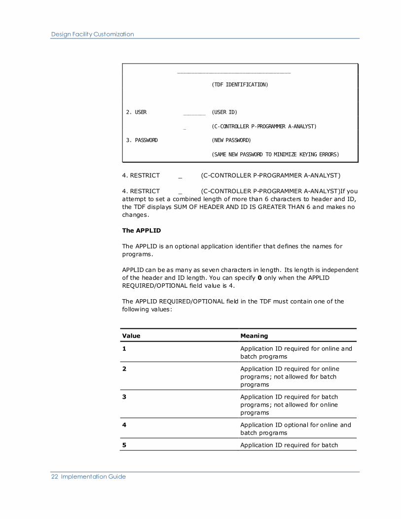
4. RESTRICT _ (C-CONTROLLER P-PROGRAMMER A-ANALYST)If you
attempt to set a combined length of more than 6 characters to header and ID,
the TDF displays SUM OF HEADER AND ID IS GREATER THAN 6 and makes no
changes.
The APPLID
The APPLID is an optional application identifier that defines the names for
programs.
APPLID can be as many as seven characters in length. Its length is independent
of the header and ID length. You can specify 0 only when the APPLID
REQUIRED/OPTIONAL field value is 4.
The APPLID REQUIRED/OPTIONAL field in the TDF must contain one of the
following values:
Value Meaning
1 Application ID required for online and
batch programs
2 Application ID required for online
programs; not allowed for batch
programs
3 Application ID required for batch
programs; not allowed for online
programs
4 Application ID optional for online and
batch programs
5 Application ID required for batch

Design Facility Customization
Chapter 2: Basic Procedures 23
Value Meaning
programs; optional for online
programs
6 Application ID required for online
programs; optional for batch programs
The APPLID REQ/OPTIONAL field is used in conjunction with APPLID LENGTH to
decide whether to display and allow an APPLID value. A length of 0 means that
APPLID is not allowed; this is the default. In the preceding example of the TDF
Installation menu, LENGTH has been changed to 3 and REQ/OPTIONAL is set at
1.
If you try to add an APPLID longer than seven characters, the TDF responds by
highlighting the field and displaying the message HIGHLIGHTED FIELD IN
ERROR.

Design Facility Customization
24 Implementation Guide
Customize the Program Format and Environment (Optional)
Use this step to customize the following:
■ Format of generated CA Telon source
■ Default target environment for CA Telon programs
■ Default format for display of data in CA Telon
Format of generated source
You can set the format of the generated CA Telon source code that is exported
from the TDF using one of the following formats:
■ Y—Compressed. Condenses the source code listing of the parameters into as
few lines as possible. Also creates short listings with more than one
parameter per line.
■ N—Noncompressed. Writes one parameter per line of source code forming
longer, but more readable members than the compressed version.
Default target environment
You can set the default environment to IMS/DC, TSO, CICS, or BATCH. This
default can be overridden on an individual program basis and in JCL.
Select your default environment as follows:
CICS
CICS generation for production or for test under the CA InterTest or other
testing tools.
IMS
IMS generation for production.
TSO
IMS generation for Test under TSO
BATCH
Batch generation for production or for test execution under TSO
To specify the default CA Telon source code output to non-compressed and the
default environment on the TDF Installation menu, enter:
■ UP in the FUNCTION field
■ IP in the ITEM field
■ Values as appropriate in the fields preceding (FORMATTING - COMPRESSION
AND ENVIRONMENT)
Design Facility Customization
Chapter 2: Basic Procedures 25
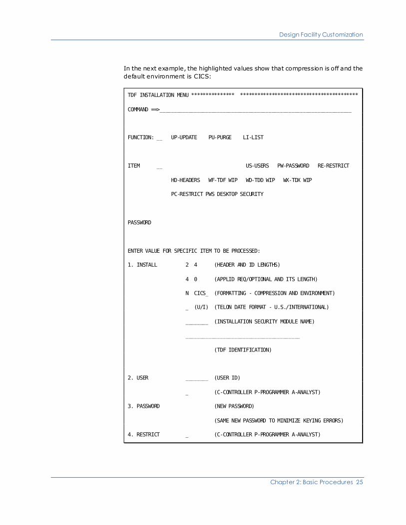
In the next example, the highlighted values show that compression is off and the
default environment is CICS:
TDF INSTALLATION MENU *************** *****************************************
COMMAND ==>___________________________________________________________________
FUNCTION: __ UP-UPDATE PU-PURGE LI-LIST
ITEM __ US-USERS PW-PASSWORD RE-RESTRICT
HD-HEADERS WF-TDF WIP WD-TDD WIP WX-TDX WIP
PC-RESTRICT PWS DESKTOP SECURITY
PASSWORD
ENTER VALUE FOR SPECIFIC ITEM TO BE PROCESSED:
1. INSTALL 2 4 (HEADER AND ID LENGTHS)
4 0 (APPLID REQ/OPTIONAL AND ITS LENGTH)
N CICS_ (FORMATTING - COMPRESSION AND ENVIRONMENT)
_ (U/I) (TELON DATE FORMAT - U.S./INTERNATIONAL)
________ (INSTALLATION SECURITY MODULE NAME)
________________________________________
(TDF IDENTIFICATION)
2. USER ________ (USER ID)
_ (C-CONTROLLER P-PROGRAMMER A-ANALYST)
3. PASSWORD (NEW PASSWORD)
(SAME NEW PASSWORD TO MINIMIZE KEYING ERRORS)
4. RESTRICT _ (C-CONTROLLER P-PROGRAMMER A-ANALYST)

Design Facility Customization
26 Implementation Guide
Customize the TDF date display format
TDF screens that display date information can do so in U.S. format (mmddyy) or
in International format (ddmmyy).
The default is U.S.
To specify the international date display format, enter:
■ UP in the FUNCTION field
■ IP in the ITEM field
■ I in the field preceding CA Telon DATE FORMAT
TDF Identification
You can optionally provide a label to identify your TDF Database. This
identification label is displayed on the TDF main menu screen.
Customize Security Environment (Optional)
Use this step to set three separate security parameters:
■ User type
■ Function restriction
■ Custom security module installation
Each item progressively provides you with security.
User security
There are three types of TDF users:
■ C—Controllers
■ A—Analysts
■ P—Programmers
Each group is restricted separately and independently, as outlined next. You can
tailor the security of each type differently.
When a user signs on to the TDF for the first time, the user is automatically
added to the system as a programmer type. The installer can add a new user to
the system or change a user's type by accessing the List TDF Users screen from
the TDF Installation sub-menu menu and entering:
■ LI in the FUNCTION field
■ US in the ITEM field

Design Facility Customization
Chapter 2: Basic Procedures 27
TELON DESIGN FACILITY USER LIST ***** ****************************************
COMMAND ==> _____________________________________________________ PAGE 01 MORE
ENTER A "Z" TO PURGE THE ID OR "U" TO UPDATE USER TYPE
SEL IDENT TYPE SEL IDENT TYPE SEL IDENT TYPE SEL IDENT TYPE
_ INSTALER P _ ________ _ _ ________ _ _ ________ _
_ ________ _ _ ________ _ _ ________ _ _ ________ _
_ ________ _ _ ________ _ _ ________ _ _ ________ _
_ ________ _ _ ________ _ _ ________ _ _ ________ _
_ ________ _ _ ________ _ _ ________ _ _ ________ _
_ ________ _ _ ________ _ _ ________ _ _ ________ _
_ ________ _ _ ________ _ _ ________ _ _ ________ _
_ ________ _ _ ________ _ _ ________ _ _ ________ _
_ ________ _ _ ________ _ _ ________ _ _ ________ _
_ ________ _ _ ________ _ _ ________ _ _ ________ _
_ ________ _ _ ________ _ _ ________ _ _ ________ _
_ ________ _ _ ________ _ _ ________ _ _ ________ _
_ ________ _ _ ________ _ _ ________ _ _ ________ _
_ ________ _ _ ________ _ _ ________ _ _ ________ _
_ ________ _ _ ________ _ _ ________ _ _ ________ _
_ ________ _ _ ________ _ _ ________ _ _ ________ _
_ ________ _ _ ________ _ _ ________ _ _ ________ _
This illustration shows the screen in the way it appears just after the initial
installation of CA Telon. Your user ID appears in place of INSTALER.
To add a new user, enter the user ID in any available IDENT field. To specify the
user type different from the default, P (programmer) enter A (analyst) or C
(controller) in the associated TYPE field.

Design Facility Customization
28 Implementation Guide
To change the type of an existing user, enter U in the associated SEL field and A,
C, or P in the TYPE field. Press PF3 to save new or changed user data and return
to the TDF Installation menu.
Alternatively, you can update a single user directly from the TDF Installation
screen by entering:
■ UP in the FUNCTION field
■ US in the ITEM field
■ Userid in the 2. USER field
■ A user type value in the second line of the 2. USER field
Function restriction
As delivered, all three user types have total access to all TDF functions. You can
tailor each type independently to your installation's requirements by restricting
the functions each type of user can perform.
To restrict a user type, on the TDF Installation menu enter: enter the following
on the Install screen:
■ UP in the FUNCTION field
■ RE in the ITEM field
■ A user type value of C, A, or P in the 4. RESTRICT field
The TDF displays the Update Installation Restrictions screen:
*PROGRMR UPDATE INSTALLATION RESTRICT *****************************************
COMMAND ==> ___________________________________________________________________
** P R I M A R Y F U N C T I O N S **
DATA ADMINISTRATION Y PROGRAM DEFINITIONS Y ONLINE Y BATCH
PANEL SPECIFICATIONS Y UTILITY FUNCTIONS Y
TSO COMMAND ACCESS Y PROTOTYPING Y
** D A T A A D M I N I S T R A T I O N **
ITEM CR UP SH PU LI ITEM CR UP SH PU LI
DBD (DL) Y Y Y Y Y PSB (PS) Y Y Y Y Y
SQL (TB/TJ) Y Y Y Y Y CICS (CQ/CJ) Y Y Y Y Y
FGRP, VSAM, SEQ Y Y Y Y Y

Design Facility Customization
Chapter 2: Basic Procedures 29
** P A N E L / P R O G R A M **
** S P E C I F I C A T I O N ** ** U T I L I T Y M E N U **
ITEM CR UP SH PU LI CO RE LI PR XP XR
IMAGE (PI) Y Y Y Y Y Y Y Y Y Y Y
PANEL (PD) Y Y Y Y Y Y Y Y Y Y Y
SCREEN (SD) Y Y Y Y Y Y Y Y Y Y Y
REPORT (RD) Y Y Y Y Y Y Y Y Y Y Y
DRIVER (DR) Y Y Y Y Y Y Y Y Y Y Y
NONTERM (ND) Y Y Y Y Y Y Y Y Y Y Y
BATCH (BD) Y Y Y Y Y Y Y Y Y Y Y
STORED (SP) Y Y Y Y Y Y Y Y Y Y Y
The first word in the title displayed on the screen is the user type represented by
your entry in the 4. RESTRICT field on the TDF Installation menu. The title of the
sample screen shown abov indicates that you can define restrictions for the
programmer user type.
The functions you can restrict are:
■ Data administration—Controls access to named DBMS types from the Data
Administration menu.
■ Panel specification—Controls access to the named entity type from wherever
in the TDF they are accessible. For example, a panel definition (PD) can be
reached through panel specification, online program definition, and batch
definition. In each case, access is controlled by the PD indicators.
■ Program definition—Controls access to online and batch program definition
functions that are not controlled by panel specification restrictions.
■ Prototyping—Controls access to the Prototyping facility. commands. Valid
for the mainframe TSO TDF only.
■ Utility functions—Controls access to the named entity type from the Utilities
menu.
In the field associated with each major function, you can turn a restriction on or
off by entering one of these values:
■ Y—User type is allowed to perform the function
■ N—User type is not allowed to perform the function
Design Facility Customization
30 Implementation Guide
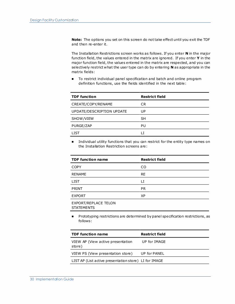
Note: The options you set on this screen do not take effect until you exit the TDF
and then re-enter it.
The Installation Restrictions screen works as follows. If you enter N in the major
function field, the values entered in the matrix are ignored. If you enter Y in the
major function field, the values entered in the matrix are respected, and you can
selectively restrict what the user type can do by entering N as appropriate in the
matrix fields:
■ To restrict individual panel specification and batch and online program
definition functions, use the fields identified in the next table:
TDF function Restrict field
CREATE/COPY/RENAME CR
UPDATE/DESCRIPTION UPDATE UP
SHOW/VIEW SH
PURGE/ZAP PU
LIST LI
■ Individual utility functions that you can restrict for the entity type names on
the Installation Restriction screens are:
TDF function name Restrict field
COPY CO
RENAME RE
LIST LI
PRINT PR
EXPORT XP
EXPORT/REPLACE TELON
STATEMENTS
■ Prototyping restrictions are determined by panel specification restrictions, as
follows:
TDF function name Restrict field
VIEW AP (View active presentation
store)
UP for IMAGE
VIEW PS (View presentation store) UP for PANEL
LIST AP (List active presentation store) LI for IMAGE

Design Facility Customization
Chapter 2: Basic Procedures 31
TDF function name Restrict field
LIST PS (List presentation store) LI for PANEL
■ Within Data Administration (Option 2), the z/OS-specific special function CA
(DB2 tables) are controlled as follows:
TDF function name Restrict field
CA (Catalog Import)<% DB2 CREATE
Custom security module
You may require non-functional security that is more restrictive than just
keeping types of users from certain TDF functions. For example, you may want
to restrict certain programmer user IDs from accessing particular headers in the
TDF.
To implement this type of security, you must write a custom security module.
If you are running the TDF under TSO, you must link the security module
REUSABLE and place it in your CA Telon execution LOAD library. If you are
running the TDF under CICS, you must link it RESUSABLE and place it in your CA
Telon CICS LOAD library.
In either case, you must also update the TDF installation. On the TDF Installation
menu, enter:
■ UP in the FUNCTION field
■ IN in the ITEM field
■ Module-name in the INSTALLATION SECURITY MODULE NAME field
This causes the TDF to call the module from every TDF menu and from most of
the list screens.

Design Facility Customization
32 Implementation Guide
List Headers
You can list all the headers used in the system. This is not a task in the
installation/customization process, but it is a utility that allows the installer to
track system usage. On the TDF Installation menu, enter:
■ LI in the FUNCTION field
■ HD in the ITEM field
The TDF displays the List Headers screen, as shown next. The displayed list of
headers vary; this is a sample display. For more information, see Test the TDF
(see page 17).
TDF ****** LIST OF HEADERS ********** ****************************************
COMMAND ==>
*** H E A D E R S ***
AA AD CM CS DG DR DV ED FR GK
HL JG JS KD LH LS MB MM OE PM
PP PS SS TC TN TR TU WF WS

Design Facility Customization
Chapter 2: Basic Procedures 33
Modify Installation Profile Defaults (Optional)
CA Telon provides a predefined set of installation profile defaults. These defaults
can be modified globally by the installer. Each user can also modify his or her
profile defaults.
To modify the installation profile defaults globally so that each new user receives
a new set of defaults, do the following:
■ On the TDF Main Menu, enter 1 in the FUNCTION field
■ On the User Profile Maintenance menu, select any option, specify new
defaults on the display screen, and return to the menu
■ Repeat the preceding step for other options, as needed
■ Return to the TDF Main Menu and enter INSTALL on the COMMAND line
■ On the TDF Installation menu, enter:
– UP in the FUNCTION field
– IP in the ITEM field
You receive a message saying that the installation profile has been updated.
From this point on, all new users who enter the CA Telon Design Facility have the
modified installation profile merged into their user profile. You can verify this
process by looking at a new user's profile defaults.
To apply the modified installation defaults to an established user, purge the user
from the TDF. The next time the user enters the CA Telon Design Facility, they
receive the modified installation defaults.
Note: Do not purge any user who is currently in session.
The installation profile is determined by values in these fields:
■ On the Update Program Definition Defaults screen:
– LANG
– OUTIFIL
– ALARM
– HELP
– EOFKEY
– HOLD

Clean Up Work-In-Progress (WIP) Files
34 Implementation Guide
■ On the Update Environment Definition Defaults screen:
– CICS:
– PSBSCHD
– TRACE
– LINEOPT
– BMS
– SPASTG
– IOASTG
– TPBSTG
– IMS:
– LINKOPT
– CONVERS
Note: You can specify similar environment definition defaults for the BATCH,
and STORED environments.
■ On the Update PF Keys Definition screen, all PF/PA key definitions
■ On the Update Session Controls screen:
– All IMAGE CHARACTER fields
– All FIELD SELECTION fields
– FORMAT and PSB (within ENVIRONMENT)
– DITTO CHARACTER
– PANEL SIZE
– USER MODE
– PDSCOPY DSNAME
– DG SEPARATORS
Clean Up Work-In-Progress (WIP) Files
The clean-up functions for WIP files are described in this section.
Important! You should be aware that these purge options completely eliminate
all information for the selected WIP files.

Clean Up Work-In-Progress (WIP) Files
Chapter 2: Basic Procedures 35
List Programs for WIP Files
You can list all programs currently in WIP. This is not a task in the
installation/customization process, but it is a utility that allows the purging of
WIP files. On the TDF Installation menu, enter:
■ LI in the FUNCTION field
■ WF in the ITEM field
The TDF displays the Purge WIP Program Records screen, as shown next sample.
The displayed list of programs vary.
LIST DEFINITIONS ******************* *****************************************
COMMAND ==> PAGE 00
* ***NAME************** *************DESCRIPTION*************** USER UPDATE
TNNWPI.SD NEW PI FOWDE01 060496
Enter Z in the Select column to purge the program from the file.
List Data Administration Records for WIP Files
You can list all data administration records currently in WIP. This is not a task in
the installation/customization process, but it is a utility that allows the purging of
WIP files. On the TDF Installation menu, enter:
■ LI in the FUNCTION field
■ WD in the ITEM field
The TDF displays the Purge WIP Data Administration Records screen, as shown in
the next sample. The displayed list of records varies.
LIST DATA ADMINISTRATION INFO ******* *****************************************
COMMAND ==> PAGE 00
* ***NAME************** *************DESCRIPTION*************** USER UPDATE
NEWDL/D NEW DL FOWDE01 060496
Enter Z in the Select column to purge the record from the file.

Clean Up Work-In-Progress (WIP) Files
36 Implementation Guide
List SQL Records for WIP Files
You can list all SQL records currently in WIP. This is not a task in the
installation/customization process, but it is a utility that allows the purging of
WIP files. On the TDF Installation menu, enter:
■ LI in the FUNCTION field
■ WX in the ITEM field
The TDF displays the Purge WIP SQL Records screen, as shown in the next
sample. The displayed list of SQL records will vary.
LIST SQL **************************** *****************************************
COMMAND ==> PAGE 00
* ******SQL QUAL.NAME******* *************DESCRIPTION************ *TLNNAME* DB
DATACOM.TRGEMPL CREATED BY DATC CATALOG EXTRACT TRGEMPLC DC
TLNIDMS.JOIN IDMS TABLE JOIIN IDMSJOIN ID
Enter Z in the Select column to purge the SQL record from the file.

Generator Customization
Chapter 2: Basic Procedures 37
Generator Customization
The CA Telon Generator is the facility that translates your CA Telon source code
exported from the TDF into COBOL II, COBOL for z/OS and PL/I source code.
From there it directs the program's compilation into an executable load module.
CA Telon's Application Generator is tailored by modifying a number of the
supplied installation-modifiable parameters. With little effort, a site can tailor the
Application Generator to perform the following operations:
■ Customize the load module naming conventions
■ Customize the MFS and BMS module naming conventions
■ Force installation-defined COBOL and PL/I code into predetermined locations
in the generated programs
■ Open up additional Custom Code entry points
■ Define user-written screen field edits
■ Define system/environment defaults
■ Establish standard application ABEND handling procedures
Modify CA Telon for an application
The CA Telon code Generator is easily customized for specific applications in your
site. If an application needs its own naming conventions, standard code, work
area, additional Custom Code entry points, transfer area or transfer area size,
these can best be handled by using the facility provided by the TELONIIS macro.
The TELONIIS macro is found in your site's MACLIB and uses another macro
called TLNIIS in which all of these parameters can be set. In TELONIIS, code is
available to choose the correct TLNIIS for the program being generated during
the generation procedure. As shipped, TELONIIS has optional code to select the
correct TLNIIS by the program's header or application ID. See Further
Customization of Macro Libraries (see page 85) for more information about
modifying CA Telon for an application.
This section describes how to customize the CA Telon Generator. The steps you
must take to customize and test the CA Telon Generator are:
1. Copy PGMNAMES from PGMNAMED
2. Customize naming conventions (optional)
3. Customize user edit usage (optional)
4. Customize system defaults (optional)
5. Customize environment defaults (optional)
Generator Customization
38 Implementation Guide
Even if you decide to retain all delivered default options, you should become
familiar with the optional as well as required steps for Generator customization
and testing.
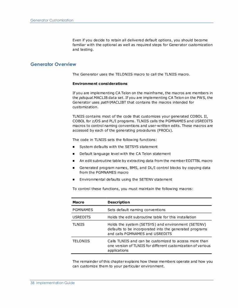
Generator Overview
The Generator uses the TELONIIS macro to call the TLNIIS macro.
Environment considerations
If you are implementing CA Telon on the mainframe, the macros are members in
the pdsqual.MACLIB data set. If you are implementing CA Telon on the PWS, the
Generator uses path\MACLIBT that contains the macros intended for
customization.
TLNIIS contains most of the code that customizes your generated COBOL II,
COBOL for z/OS and PL/I programs. TLNIIS calls the PGMNAMES and USREDITS
macros to control naming conventions and user-written edits. These macros are
accessed by each of the generating procedures (PROCs).
The code in TLNIIS sets the following functions:
■ System defaults with the SETSYS statement
■ Default language level with the CA Telon statement
■ An edit subroutine table by extracting data from the member EDITTBL macro
■ Generated program names, BMS, and DL/I control blocks by copying data
from the PGMNAMES macro
■ Environmental defaults using the SETENV statement
To control these functions, you must maintain the following macros:
Macro Description
PGMNAMES Sets default naming conventions
USREDITS Holds the edit subroutine table for this installation
TLNIIS Holds the system (SETSYS) and environment (SETENV)
defaults to be incorporated into the generated programs
and calls PGMNAMES and USREDITS
TELONIIS Calls TLNIIS and can be customized to access more than
one version of TLNIIS for different customization of various
applications
The remainder of this chapter explains how these members operate and how you
can customize them to your particular environment.

Generator Customization
Chapter 2: Basic Procedures 39
Copy PGMNAMES from PGMNAMED
To assure a clean backup copy of PGMNAMES, CA supplies you with the
PGMNAMED macro so that you can create PGMNAMES.
To set up your release of Generator, make a copy of the PGMNAMED macro,
assigning it the name PGMNAMES in the data set (for the mainframe) or the
directory (for PWS) that you use as your macro "execution" library.
PGMNAMES is the member that Generator uses for naming conventions. In
subsequent customization and testing steps discussed in this section, you will
modify the PGMNAMES member. All subsequent references to PGMNAMES refer
to this newly-created member.
5.0 mainframe considerations
If you are implementing CA Telon r5 on the mainframe, you cannot modify
pdsqual.TGTMAC(PGMNAMES) directly, since this dataset is under SMP/E
control. If you want to use pdsqual.TGTMAC, you must perform this macro
customization as an SMP/E USERMOD.
Customize Naming Conventions (Optional)
This step involves modifying the PGMNAMES macro which sets the Generator's
naming conventions. These naming conventions involve:
■ IMS/DC, CICS, TSO, BATCH, and STORED program name.
■ BMS map names
■ MFS names
■ PSB names
■ Transaction codes
■ Application work area
■ Application update area
■ PF-key processing copy member names

Generator Customization
40 Implementation Guide
Setting Up Names
To set up program names, complete the following:
1. Determine member naming conventions
2. Specify whether the SCREEN/APPLID parameter is required
3. Set the program header name and length
4. Set the program trailer name and length
5. Set the program ID and length
6. Set MFS control block names (if any)
7. Set program names
8. Set application COPY and/or %INCLUDE names
Each of these steps is discussed in detail next.
Step 1—Determine member naming conventions
Determine the naming conventions for each member by laying out the
combination of header, program ID, and trailer that you need. Consider the
following when you set up naming conventions:
■ Header and program ID are required.
■ You can supply as many as two characters for the header. If you need a
longer header, use the optional parameter on the SCREEN statement.
■ Program ID must be four characters on the SCREEN statement, but you can
use a substring of the program ID to compose the names.
Names generated
The names generated have the following format:
hhxxnnnnaaaaaaa where:
1. hhxx is the program header and xx is a character constant. Some examples
are:
■ For IMS/DC—TM, IM, SM, or XM
■ For CICS, Z
■ For Batch, BP
2. nnnn is the program ID
3. aaaaaaa is the application ID (APPLID)
Note: The APPLID is not used for STORED programs.

Generator Customization
Chapter 2: Basic Procedures 41
The names generated for all modules may be user-defined. These names consist
of the following parameters of the SCREEN statement combined with constant
values:
■ &SHEADER.—Header
■ &SAPPLID.—Application ID
■ &SCRNR.—Program ID
Any combination of these global parameters is allowed. As delivered, PGMNAMES
uses only the two-character header and the four-character program ID. All other
characters are constants. Note that the application ID is not used as delivered.
You can assign as many as eight characters to program names in COBOL and
seven characters for PL/I. The APPLID is not used as delivered. Its length
defaults to zero. For more information, see Customize Naming Conventions
(Optional) (see page 39).
The parts of the program name come into play only when actually establishing
and coding the naming conventions into PGMNAMES.
For example, consider a COBOL program made from a TDF screen definition with
a header of TR and a TDF screen ID of MENU. In an IMS/DC environment, the CA
Telon Generator creates a name TRIMMENU. For a CICS environment the CA
Telon Generator creates a name of TRCPMENU. For more information, see
Customize Naming Conventions (Optional) (see page 39).
If the naming conventions above do not meet your naming standards, you can
define an entirely different method of generating names. See the PGMNAMES
macro.
Step 2—Specify if SCREEN/APPLID required
If you use the &SAPPLID. parameter, specify edits indicating whether it is
required and its length. As delivered, the &SAPPLID. parameter is not used. It is
included in the SCREEN macro that is set in the APPLID parameter on the
SCREEN statement.
To require APPLID on the SCREEN statement, delete the AGO line. Delete the
next AGO if APPLID is required or optionally for online, batch, or both. If APPLID
is not used in your generated names, leave the AGO as is. The AGO line is
provided next:
AGO .GLOBAPP

Generator Customization
42 Implementation Guide
Specify whether the APPLID is required for online and batch, online only, or batch
only by including or deleting the AIF lines shown next, as follows:
■ If the APPLID is required for online and batch, use the first AIF line (1) and
delete the other lines (2 and 3)
■ If the APPLID is required for online only, use the second AIF line (2) and
delete the other lines (1 and 3)
■ If the APPLID is required for batch only, use the third AIF line (3) and delete
the other lines (1 and 2)
(1) AIF ('&SAPPLID'. NE '').GLOBAPP
(2) AIF ('&SAPPLID'. NE '' OR &BATCH).GLOBAPP
(3) AIF ('&SAPPLID'. NE '' OR NOT &BATCH).GLOBAPP
MNOTE 16,'GLOBALS - REQUIRED PARAMETER OMITTED: APPLID '
Step 3—Set program header name and length
This section provides examples of how to set:
■ COBOL names
■ PL/I execution time options
■ PL/I names
Specifying the program language
To specify the program language, include the following AIF line immediately after
the .GLOBAPP ANOP line:
AIF ('&PGMLANG'. EQ 'PLI').STPLNM
Setting COBOL program header name and length
The sample code displayed next shows how to set a COBOL program header
name and its length.
Note: The variable &HDRLTH. contains the length of the entity header.
&PGMBHDR. SETC '&SHEADER.BP' PROGRAM HEADER BATCH
&PGMTHDR. SETC '&SHEADER.TM' PROGRAM HEADER TSO TEST
&PGMDHDR. SETC '&SHEADER.IM' PROGRAM HEADER IMS DRIVER
&PGMIHDR. SETC '&SHEADER.IM' PROGRAM HEADER IMS DYNAMIC
&PGMSHDR. SETC '&SHEADER.SM' PROGRAM HEADER IMS STATIC SUBPROGRAM
&PGMLHDR. SETC '&SHEADER.XM' PROGRAM HEADER IMS ALIAS
&PGCPHDR. SETC '&SHEADER.CP' PROGRAM HEADER CICS
&PGCCHDR. SETC '&SHEADER.CC' PROGRAM HEADER CICS CLIENT
&PGCSHDR. SETC '&SHEADER'. PROGRAM HEADER CICS SERVER
&PGNPHDR. SETC '&SHEADER.NP' PROGRAM HEADER CICS NONTERM
&PGSPHDR. SETC '&SHEADER.SP' PROGRAM HEADER STORED PROCEDURE
&PGMBHDL. SETA K'&PGMBHDR. PROGRAM HEADER LENGTH BATCH

Generator Customization
Chapter 2: Basic Procedures 43
&PGMTHDL. SETA K'&PGMTHDR. PROGRAM HEADER LENGTH TSO
&PGMDHDL. SETA K'&PGMDHDR. PROGRAM HEADER LENGTH IMS DRIVER
&PGMIHDL. SETA K'&PGMIHDR. PROGRAM HEADER LENGTH IMS DYNAMIC
&PGMSHDL. SETA K'&PGMSHDR. PROGRAM HEADER LENGTH IMS STATIC
&PGMLHDL. SETA K'&PGMLHDR. PROGRAM HEADER LENGTH IMS ALIAS
&PGCPHDL. SETA K'&PGCPHDR. PROGRAM HEADER LENGTH CICS
&PGCCHDL. SETA K'&PGCCHDR. PROGRAM HEADER LENGTH CICS CLIENT
&PGCSHDL. SETA K'&PGCSHDR. PROGRAM HEADER LENGTH CICS SERVER
&PGNPHDL. SETA K'&PGNPHDR. PROGRAM HEADER LENGTH CICS NONTERM
&PGSPHDL. SETA K'&PGSPHDR. PROGRAM HEADER LENGTH STORED PROC
AGO .PGN5000
.PGN4000 ANOP
Setting PL/I default program options
The following sample code shows how to set PL/I default program options.
PLIXOPT TSO,STORAGE=STATIC,REORDER=NO,ALIGN=UNALIGNED
PLIXOPT IMS,STORAGE=STATIC,REORDER=NO,ALIGN=UNALIGNED
PLIXOPT BATCH,STORAGE=STATIC,REORDER=NO,ALIGN=UNALIGNED
Setting PL/I program header name and length
The following sample code shows how to set the PL/I program header name and
length.
&PGMBHDR. SETC '&SHEADER.B' PROGRAM HEADER BATCH
&PGMTHDR. SETC '&SHEADER.T' PROGRAM HEADER TSO TEST
&PGMDHDR. SETC '&SHEADER.I' PROGRAM HEADER IMS DRIVER
&PGMIHDR. SETC '&SHEADER.I' PROGRAM HEADER IMS DYNAMIC
&PGMSHDR. SETC '&SHEADER.S' PROGRAM HEADER IMS STATIC
&PGMLHDR. SETC '&SHEADER.X' PROGRAM HEADER IMS ALIAS
&PGCPHDR. SETC '&SHEADER.P' PROGRAM HEADER CICS
&PGNPHDR. SETC '&SHEADER.N' PROGRAM HEADER CICS NONTERM
&PGSPHDR. SETC '&SHEADER.2' PROGRAM HEADER STORED PROCEDURE
&PGMBHDL. SETA K'&PGMBHDR. PROGRAM HEADER LENGTH BATCH
&PGMTHDL. SETA K'&PGMTHDR. PROGRAM HEADER LENGTH TSO
&PGMDHDL. SETA K'&PGMDHDR. PROGRAM HEADER LENGTH IMS DRIVER
&PGMIHDL. SETA K'&PGMIHDR. PROGRAM HEADER LENGTH IMS DYNAMIC
&PGMSHDL. SETA K'&PGMSHDR. PROGRAM HEADER LENGTH IMS STATIC
&PGMLHDL. SETA K'&PGMLHDR. PROGRAM HEADER LENGTH IMS ALIAS
&PGCPHDL. SETA K'&PGCPHDR. PROGRAM HEADER LENGTH CICS
&PGCCHDL. SETA K'&PGCCHDR. PROGRAM HEADER LENGTH CICS CLIENT
&PGCSHDL. SETA K'&PGCSHDR. PROGRAM HEADER LENGTH CICS SERVER
&PGNPHDL. SETA K'&PGNPHDR. PROGRAM HEADER LENGTH CICS NONTERM
&PGSPHDL. SETA K'&PGSPHDR. PROGRAM HEADER LENGTH STORED PROC
.PGN5000 ANOP
Generator Customization
44 Implementation Guide
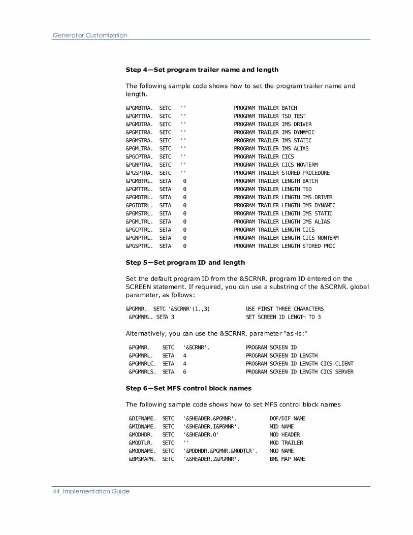
Step 4—Set program trailer name and length
The following sample code shows how to set the program trailer name and
length.
&PGMBTRA. SETC '' PROGRAM TRAILER BATCH
&PGMTTRA. SETC '' PROGRAM TRAILER TSO TEST
&PGMDTRA. SETC '' PROGRAM TRAILER IMS DRIVER
&PGMITRA. SETC '' PROGRAM TRAILER IMS DYNAMIC
&PGMSTRA. SETC '' PROGRAM TRAILER IMS STATIC
&PGMLTRA. SETC '' PROGRAM TRAILER IMS ALIAS
&PGCPTRA. SETC '' PROGRAM TRAILER CICS
&PGNPTRA. SETC '' PROGRAM TRAILER CICS NONTERM
&PGSPTRA. SETC '' PROGRAM TRAILER STORED PROCEDURE
&PGMBTRL. SETA 0 PROGRAM TRAILER LENGTH BATCH
&PGMTTRL. SETA 0 PROGRAM TRAILER LENGTH TSO
&PGMDTRL. SETA 0 PROGRAM TRAILER LENGTH IMS DRIVER
&PGIDTRL. SETA 0 PROGRAM TRAILER LENGTH IMS DYNAMIC
&PGMSTRL. SETA 0 PROGRAM TRAILER LENGTH IMS STATIC
&PGMLTRL. SETA 0 PROGRAM TRAILER LENGTH IMS ALIAS
&PGCPTRL. SETA 0 PROGRAM TRAILER LENGTH CICS
&PGNPTRL. SETA 0 PROGRAM TRAILER LENGTH CICS NONTERM
&PGSPTRL. SETA 0 PROGRAM TRAILER LENGTH STORED PROC
Step 5—Set program ID and length
Set the default program ID from the &SCRNR. program ID entered on the
SCREEN statement. If required, you can use a substring of the &SCRNR. global
parameter, as follows:
&PGMNR. SETC '&SCRNR'(1.,3) USE FIRST THREE CHARACTERS
&PGMNRL. SETA 3 SET SCREEN ID LENGTH TO 3
Alternatively, you can use the &SCRNR. parameter "as-is:"
&PGMNR. SETC '&SCRNR'. PROGRAM SCREEN ID
&PGMNRL. SETA 4 PROGRAM SCREEN ID LENGTH
&PGMNRLC. SETA 4 PROGRAM SCREEN ID LENGTH CICS CLIENT
&PGMNRLS. SETA 6 PROGRAM SCREEN ID LENGTH CICS SERVER
Step 6—Set MFS control block names
The following sample code shows how to set MFS control block names
&DIFNAME. SETC '&SHEADER.&PGMNR'. DOF/DIF NAME
&MIDNAME. SETC '&SHEADER.I&PGMNR'. MID NAME
&MODHDR. SETC '&SHEADER.O' MOD HEADER
&MODTLR. SETC '' MOD TRAILER
&MODNAME. SETC '&MODHDR.&PGMNR.&MODTLR'. MOD NAME
&BMSMAPN. SETC '&SHEADER.Z&PGMNR'. BMS MAP NAME

Generator Customization
Chapter 2: Basic Procedures 45
Step 7—Set program names
The following sample code shows how to set program names. Note that in this
step you use the global parameters that you set in the preceding steps. The
formula for each name does not require change.
&BCHNAME. SETC '&PGMBHDR.&PGMNR.&PGMBTRA'. PGM NAME - BATCH
&TSONAME. SETC '&PGMTHDR.&PGMNR.&PGMTTRA'. PGM NAME - TSO TEST
AIF (&DRIVER).PGN4000
&IMSNAME. SETC '&PGMIHDR.&PGMNR.&PGMITRA'. PGM NAME - IMS DYNAMIC
AGO .PGN5000
.PGN4000 ANOP
&IMSNAME. SETC '&PGMDHDR.&PGMNR.&PGMDTRA'. PGM NAME - IMS DRIVER
.PGN5000 ANOP
&IMSNAME. SETC '&PGMIHDR.&PGMNR.&PGMITRA'. PGM NAME - IMS/PSB
&STANAME. SETC '&PGMSHDR.&PGMNR.&PGMSTRA'. PGM NAME - IMS STATIC
&IMLNAME. SETC '&PGMLHDR.&PGMNR.&PGMLTRA'. PGM NAME - IMS ALIAS
&STPNAME. SETC '&PGSPHDR.&PGMNR.&PGSPTRA'. PGM NAME - STORED PROC
&CICSNMP. SETC '&PGCPHDR.&PGMNR.&PGCPTRA'. PGM NAME - CICS SCREEN
&CICSNMC. SETC '&PGCCHDR.&PGMNR.&PGCPTRA'. PGM NAME - CICS CLIENT
&CICSNMS. SETC '&PGCSHDR.&PGMNR.&PGCPTRA'. PGM NAME - CICS SERVER
&CICSNMN. SETC '&PGNPHDR.&PGMNR.&PGNPTRA'. PGM NAME - CICS NONTERM
&PGIMTRN. SETC '&IMSNAME'. PGM IMS TRAN NAME DEFAULT
&CICSTRN. SETC '&PGMNR'. CICS TRANSACTION CODE
&PGCTSUF. SETC 'SPA' CICS TS QUEUE SUFFIX
Step 8—Set application COPY and/or %INCLUDE names
The names generated for all modules may be user-defined. These names consist
of the following parameters of the SCREEN statement combined with constant
values:
■ &SHEADER.—Header
■ &SAPPLID.—Application ID
■ &SCRNR.—Program ID
Any combination of these global parameters is allowed. As delivered, PGMNAMES
uses only the two-character header and the four-character program ID.
The following sample code shows how to set the names for the HHPCBS,
HHPROC, HHWKAREA, and HHUPDTA COPY/INCLUDE names used in generating
CA Telon programs.
&TLNPCBS. SETC '&SHEADER.PCBS' HHPCBS
&TLNPROC. SETC '&SHEADER.PROC' HHPROC
&TLNWORK. SETC '&SHEADER.WKAREA' HHWKAREA
&TLNUPDT. SETC '&SHEADER.UPDTA' HHUPDTA
&TLNPFK. SETC '&SHEADER.PFK' HHPFKEY

Generator Customization
46 Implementation Guide
You must ensure that any changes that you make to the length of the program
header, ID, or APPLID (for IMS/DC) are reflected in the TDF naming
customization. For more information, see Customize Naming Conventions
(Optional).
You can use the same basic elements to design the names the Generator builds
for standard copy members:
Target Elements
IMS/DC ■ Screen, driver, report, or batch
header
■ A character constant
■ APPLID
■ Screen, driver, report, or batch ID
CICS ■ Screen, a client nonterminal, or
batch header
■ Character constant PLIXOPT
CICS,STORAGE=AUTO,REORDER
=NO,ALIGN=UNALIGNED
■ APPLID
■ Screen, nonterminal, or batch ID
CICS Server ■ Server header
■ APPLID parameters are listed in
the following chart.
■ Server ID
BATCH ■ Batch header
■ Character constant
■ APPLID parameters are listed in
the following chart.
■ Batch ID
STORED ■ Stored procedure header
■ Character constant
■ Stored procedure ID
Since standard copy members often are global to an entire application,
parameters are listed in the following chart. You seldom need to use the program
ID in the copy member name.
Generator Customization
Chapter 2: Basic Procedures 47
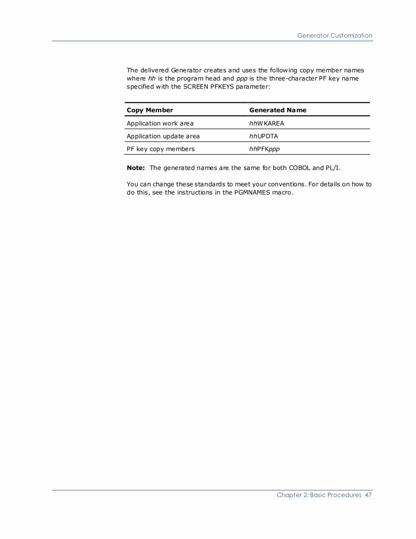
The delivered Generator creates and uses the following copy member names
where hh is the program head and ppp is the three-character PF key name
specified with the SCREEN PFKEYS parameter:
Copy Member Generated Name
Application work area hhWKAREA
Application update area hhUPDTA
PF key copy members hhPFKppp
Note: The generated names are the same for both COBOL and PL/I.
You can change these standards to meet your conventions. For details on how to
do this, see the instructions in the PGMNAMES macro.

Generator Customization
48 Implementation Guide
Customize User Edit Usage (Optional)
You can perform this step optionally to define user-defined FIELD FLDTYPE edit
routines in the USREDITS macro.
1. Place user-defined edit routines in a load library identified by the USERSUBR
parameter in the generate, compile, and link procedures. See User-Defined
Subroutines (see page 120) for more information about user-defined
subroutines in the mainframe environment.
2. Identify these custom routines in the USREDITS macro. You must identify
numeric edits and all edits requiring extended parameters. You do not have
to identify alpha edits that use only standard parameter lists. But as an
option, you can require that all edits be identified in USREDITS. You control
this with the edit error global &EDTERR. set in USREDITS.
The purpose of USREDITS is to maintain consistency in CA Telon and to prevent
the duplication of effort in writing field edits by multiple systems in an
installation. You should check any new field edit requirements for a specific
system against this edit table. If a new field is needed, an entry from USREDITS
is placed in this table.
All CA Telon-supplied FLDTYPE edit subroutines are identified in the EDITTBL
macro. Because the generated programs use information in EDITTBL and
USREDITS, you must define all numeric edits, and all edits that require more
than the default number of parameters, by modifying USREDITS. If not, a
compile error results in the generated program.
You can set your own level of severity for flagging field edits that are not found
in the USREDITS table by setting the value for the global &EDTERR. parameter,
discussed later in this section.
Follow the next steps to modify USREDITS.
Step 1—Define &EDTERR. values
To specify whether all field-type edits are required, set the &EDTERR. global
parameter to the desired error severity for assemblies in which field-type edits
are called but not defined in this table. Valid values are:
■ 0—No condition code set, fields using undefined edits are flagged as
undefined.
■ 4—Condition code 4&semi. field is flagged and condition code set. The
compile step is still executed.
■ 16—Condition code 16&semi. fields are flagged and condition code set. The
compile step is not executed.

Generator Customization
Chapter 2: Basic Procedures 49
The &EDTERR. parameter, as it appears in the USREDITS macro, is shown next:
&EDTERR. SETA 0 < SET THIS VALUE TO CONDITION CODE DESIRED
Note: The &EDTERR. may also be customized in your TLNIIS macro using the
SETSYS parameter SEDTERR. If a value is specified for SEDTERR. If a value is
specified for SEDTERR, that value overrides the &EDTERR. value specified in
USREDITS. SEDTERR gives you the option of using different versions of TLNIIS
for diferent appplications and specifying different EDTERR values for each, as
appropriate.
Step 2—Code DFNWKFLD
Code a DFNWKFLD statement to define alternative numeric WORKFLDs that
numeric edits use. All DFNWKFLD statements must precede DFNEDIT
statements. Coding is in the table-standard macro Assembler. The DFNWKFLD
statement is shown next:
DFNWKFLD WKFLDID=N,COBPIC='COBOL PIC',PLIPIC='PLI DEFINITION'
Parameters for the DFNWKFLD statement are:
■ WKFLDID—The identifier for the work field. Valid values are the numbers 1
through 10.
■ COBPIC—The COBOL picture clause for the field. You must enclose the
actual picture clause in single quotes, for example:
COBPIC='S9(16)V9(2) COMP-3'
■ PLIPIC—The PL/I definition for the field. You must enclose this definition in
single quotes, for example:
PLIPIC='FIXED DECIMAL (14,2)'
For any parameter value that contains a single quote, code a double quote,
for example:
PLIPIC='PIC ''(10)9V(4)9T'' '
The field name generated is WORKFLD-NUMERIC-&WKFLDID. After the work
field is defined you can reference it in a DFNEDIT statement.
The USREDITS edit table definition begins with DFNWKFLD statements. In the
DFNWKFLD statement shown next, note that the default DFNWKFLD is supplied
in the EDITTBL macro. You can use this workfield by referencing WKFLDID=1. To
add numeric workfields, start at WKFLDID=2.
DFNWKFLD WKFLDID=1,
COBPIC='S9(16)V9(2)', ... C
PLIPIC='PIC ''(13)9V9T''' ... C

Generator Customization
50 Implementation Guide
Step 3—Code DFNEDIT
After generating a work field, code the DFNEDIT statement to define an edit to
the system. Coding is in table-standard macro Assembler.
DFNEDIT NNNNNNN,
OIUSE=OUTPUT/INPUT/OUTIN
LANG=COB/PLI/ASM OR (LANG OUT,LANG IN)
DATATYP=NUMERIC/ALPHA/BIT OR (TYP OUT,TYP IN)
WKFLDID=P,
EXTCNT=(X,Y),
OEXDFLT=(OEX1,OEX2,..OEXN),
IEXDFLT=(IEX1,IEX2,..IEXN)
Parameters for the DFNEDIT statement are:
■ NNNNNNN —A one- to seven-byte edit name, except for PL/I where the
maximum length is six bytes, where NNNNNNN is the load module
name&semi. valid formats for input and output edit load module names are:
– INNNNNNN—Input edit load module name
– ONNNNNNN—Output edit load module name
Note: The edit name in the sample above does not contain the I or O prefix.
■ OIUSE —The edit type&semi. values are:
– OUTPUT—Output edit
– INPUT—Input edit
– OUTIN—OUTIN edit
■ LANG —The language in which the edit is written&semi. values are:
– COB—COBOL
– ASM—Assembler
– PLI—PL/I
For OUTIN edits written in an output language of COBOL and an input
language of Assembler, code the following LANG= parameter:
LANG=(COB,ASM)
■ DATATYP —The datatype of an intermediate workfield to be used by the edit
subprogram&semi. possible values are:
– ALPHA—CA Telon's alpha workfield
– NUM—CA Telon's numeric workfield
– BIT—Bit string (PL/I only)
For OUTIN edits written with an output datatype of ALPHA and an input
datatype of numeric, code the following DATATYP= parameter:
DATATYP=(ALPHA,NUM)

Generator Customization
Chapter 2: Basic Procedures 51
■ TPICHK —A parameter indicating that a check for blanks will be made
before an edit is performed&semi. values are:
– Y—A check for blanks is made prior to performing the edit
– N—An edit occurs unconditionally, regardless of whether the input buffer
is blank
■ WKFLDID —The WKFLDID of the intermediate workfield that the edit uses.
Valid values are the numbers 1 through 10.
You must define the WKFLDID with a DFNWKFLD statement before
referencing it on a DFNEDIT statement. Code this parameter only if the edit
uses a definition different from the default workfield definitions de livered
with CA Telon, which are:
– COBOL—S9(11)V9(7)
– PL/I—PIC '(10)9V(4)9T'
■ LOCATION —The identifiers where the edit will be executed.
– C—The edit is on the client.
– S—The edit is on the server.
– B—The edit is on both the client and the server.
■ EXTCNT —The number of input and output extensions to the parameter list
for the edit, where:
– X is the number (0-9) of output extensions to the parameter list for this
edit. The default is 0.
– Y is the number (0-9) of input extensions to the parameter list for this
edit. The default is 0.
If the field edit is not an OUTIN type or if the extension count is equal to the
input extension count, you need to code only one parameter for EXTCNT, for
example:
EXTCNT=2

Generator Customization
52 Implementation Guide
■ OEXDFLT —The default output parameter extensions for the field edit.
If the EXTCNT parameter for an edit is not 0, you must code the number
specified in the EXTCNT parameter for this edit. If valid datanames are not
available for extension defaults, the defaults specified should represent the
field type for documentation purposes, for example:
OEXDFLT=(DATABASE-PCB,SEGMENT-IOAREA)
■ IEXDFLT —The default input parameter extensions for the field edit.
If the EXTCNT parameter for an edit is not 0, you must code the number
specified in the EXTCNT parameter for this edit. If valid datanames are not
available for extension defaults, the defaults specified should represent the
field type for documentation purposes, for example:
IEXDFLT=(DATABASE-PCB,SEGMENT-IOAREA)
The next sample shows an input edit definition, written in COBOL, that accesses
a database to determine if the department number is valid.
DFNEDIT DEPT,OIUSE=INPUT,LANG=COB,DATATYP=ALPHA, ... C
EXTCNT=1,IEXDFLT=DEPT-PCB,TPICHK=N
Customize System Defaults (Optional)
Use this step to modify parameters in the SETSYS statements in the TLNIIS
macro. These parameters set installation defaults for the overall environment CA
Telon is working in.
Review the following parameters and their defaults. As needed, you can change
them in the TLNIIS macro.
For a list of all SETSYS parameters and the environments in which they are used,
see the appendix, "SETSYS Parameters."
SETSYS Statement
The SETSYS statement sets system default values pertaining to all programs
generated in all CA Telon environments (for example, IMS/DC, CICS, BATCH,
STORED). For more information about SETSYS parameters and the
environments in which they are used, see the appendix, "Implementation
Issues." The SETSYS parameters are described next.
ABTDPGM=(lang, program, [, lang, program])
Abnormal termination level-2 default program parameter. Used to specify the
default program to be invoked dynamically to handle the abend situation for the
CA Telon program language defined.

Generator Customization
Chapter 2: Basic Procedures 53
ABTERRM=
Abnormal termination level-2 default error message parameter. Used when
ABTMODE=ERRM. Contains the name of a variable to contain the error message.
ABTMODE=ABEND/ERRM/XFER
Abnormal termination level-2 mode parameter. Valid values are:
■ ABEND—Allow the system to handle the error
■ ERRM—Display an error message on the current screen, where ABTERRM
points to a variable name to contain the error message.
■ XFER—Transfer to a program ID specified in ABTXFER when the error is
found.
ABTPRM=(parm1,parm2,..)
Abnormal termination level-2 ADLAABT (or ADMAABT) additional parameters.
Used if ABTPRMG has a value of Y.
ABTPRMG=Y/N
Abnormal termination level-2 ADLAABT (or ADMAABT) additional parameter
flag. Valid values are:
■ Y—Add parameters specified in ABTPRM to ADLAABT (or ADMAABT calls)
■ N—Leave ADLAABT (or ADMAABT ) calls with default parameter list
ABTXFER=program-name
Abnormal termination level-2 transfer program. Contains the name or the
program ID to which to transfer when an error is found and when
ABTMODE=XFER.
ALARM=Y/N
Indicates whether the terminal alarm sounds automatically when an error
highlighting attribute is set in the program output buffer. Values are:
■ Y—Yes; you can override ALARM in all CA Telon programs
■ N—(Default) The terminal alarm does not sound automatically
BRCSRCK=Y/N
Indicates whether a code should be generated for a CURSOR OPEN during a
BROWSE (SQL only). Values are:

Generator Customization
54 Implementation Guide
■ Y—Yes
■ N—(Default) No
CLISERV=Y/N
Indicates whether the CICS program should be generated as a client/server.
Values are:
■ Y—Yes
■ N—(Default) No
COBVERS=2/3—Specifies which version of COBOL CA Telon should generate
for. Valid values are:
■ 2—COBOL II
■ 3—(Default) COBOL FOR z/OS
Note: It is also possible to specify a value for COBVERS through the SYSPARM in
JCL. If COBVERS is set through the SYSPARM, that value takes precedence over
all others. See the Installation guide for additional information about SYSPARM.
COB88LV=SINGLE/MULTIPLE
Indicates how COBOL-88-level data definitions appear. Values are:
■ SINGLE—Generate one COBOL-88 level data definition per line for
compatibility with certain optimizers and compilers.
■ MULTIPLE—(Default) Generate more than one COBOL-88 level data
definition per line.
CONFCPY=copyname/NONE
The standard COBOL configuration section COPY member name.
This parameter adds copyname, a standard copy member, to the COBOL
Configuration Section of every COBOL program generated. For example, you can
use this to include custom code to change the decimal point to a comma for
European numbers. Values are:
■ copyname—COPY member name
■ NONE—(Default) No COPY statement

Generator Customization
Chapter 2: Basic Procedures 55
DB2DATE= (###,date-format)
Indicates the date formats for SQL where:
■ ### is the date format code&semi. Values are:
– USA—(Default) MM/DD/YYYY
– EUR—DD.MM.YYYY
– ISO—YYYY-MM-DD
– JIS—YYYY-MM-DD
– LOC—Locally-defined
The date-format is required only for locally-defined formats to determine the
length and initialization value for the SQL DATE data type.
DB2TIME=(###,time-format) Indicates the time formats for SQL where
### is the time format code. Values are:
■ USA—(Default) HH:MM XM where XM is AM or PM
■ EUR—HH.MM.SS
■ ISO—HH.MM.SS
■ JIS—HH.MM.SS
■ LOC—Locally-defined
The time-format is required only for locally-defined formats to determine the
length and initialization value for the SQL TIME data type.
DCPTCMA=Y/N
Indicates whether the system generates DECIMAL-POINT IS COMMA in the
SPECIAL NAMES COPY member name. Values are:
■ Y—Yes
■ N—(Default) No
DFLTLOC=B/C/S
Indicates the default location for field edits in CICS client/server generation.
Either one or two values may be specified. If two values are specified, then the
first indicates the default location for output edits, and the second for input edits.
For example (B,C) represents "Both Client or Server" for output and "Client only"
for input. Valid values are:
■ B—(Default) Both client and server
■ C—Client only
■ S—Server only

Generator Customization
56 Implementation Guide
DLIVERS=CBLTDLI/PLITDLI/CEETDLI/AIBTDLI
Specifies which version of the DL/I CA Telon should generate. Valid values are:
■ CBLTDLI (Default)
■ PLITDLI
■ CEETDLI
■ AIBTDLI
Note: If DLIVERS is set to CBLTDLI for a PL/I program or PLITDLI for aCOBOL
program, a warning MNOTE (TLMIIS44) is issued and the value is changed to
match the language.
DRIVSSA=Y/N
Indicates whether the system generatex SSAs within a driver. Values are:
■ Y—Generate SSAs within a driver
■ N—(Default) Do not generate SSAs within a driver
DYNCALL=Y/N
Specifies whether CA Telon should generate COBOL calls to subroutines (field
edits, screen I/O routines, abend routines, and so forth) as DYNAMIC or STATIC.
A dynamic call references the called program using a variable name. A static call
references the program name directly. Values are:
■ Y—Generate dynamic calls
■ N—(Default) Generate static calls
EOFKEY=Y/N
Indicates whether the system generates code to force the modified data tag for
Input or Outin data to be turned on when the data is passed from the program to
the terminal. Valid only for IMS/DC. Values are:
■ Y—Yes. Forces all input data to be mapped from the terminal, allowing the
application user to use the EOF key to erase a field without striking any other
key. Also causes more line traffic, but assures correct data retrieval.
■ N—No. Allows for efficient line traffic, but you cannot use the EOF key unless
you strike another key in addition to it.
Note: In the CICS environment, the value of this parameter is meaningless.
Enter Y or N.
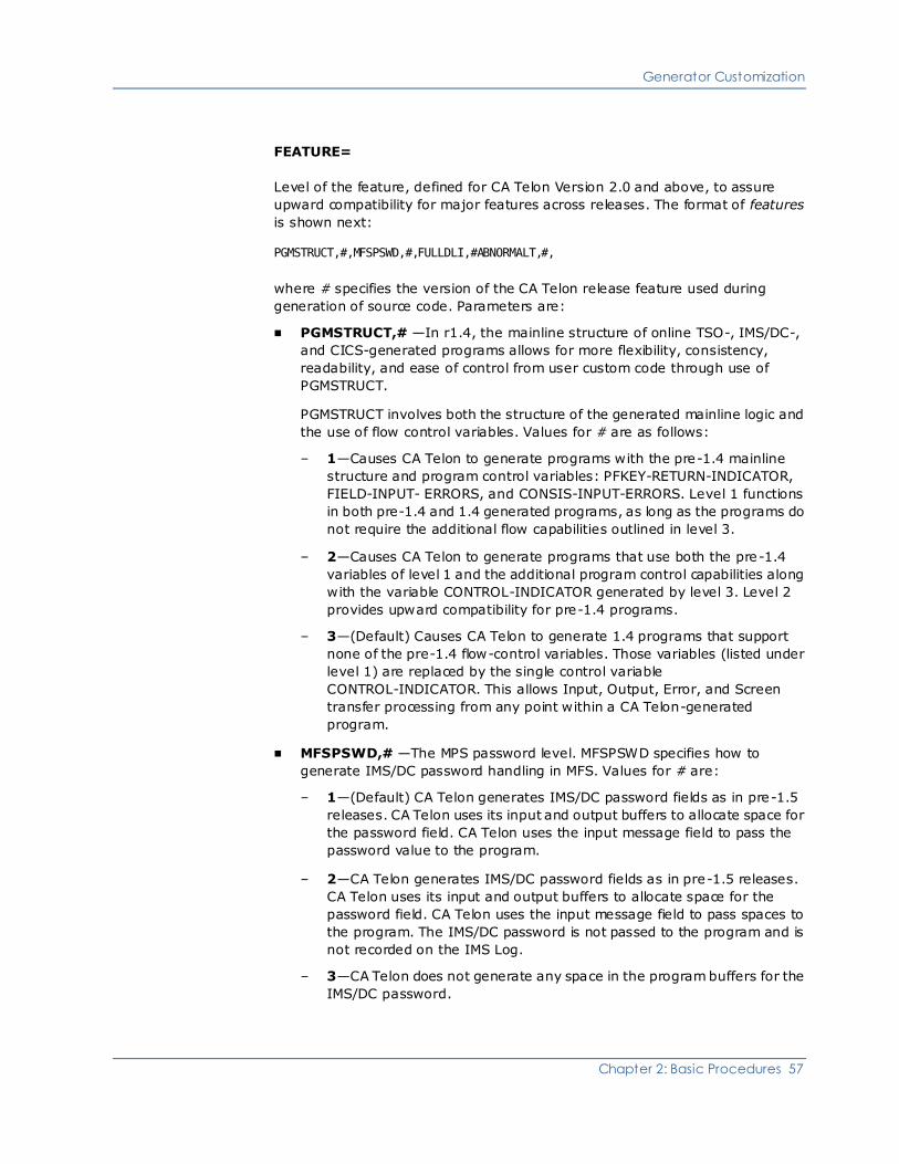
Generator Customization
Chapter 2: Basic Procedures 57
FEATURE=
Level of the feature, defined for CA Telon Version 2.0 and above, to assure
upward compatibility for major features across releases. The format of features
is shown next:
PGMSTRUCT,#,MFSPSWD,#,FULLDLI,#ABNORMALT,#,
where # specifies the version of the CA Telon release feature used during
generation of source code. Parameters are:
■ PGMSTRUCT,# —In r1.4, the mainline structure of online TSO-, IMS/DC-,
and CICS-generated programs allows for more flexibility, consistency,
readability, and ease of control from user custom code through use of
PGMSTRUCT.
PGMSTRUCT involves both the structure of the generated mainline logic and
the use of flow control variables. Values for # are as follows:
– 1—Causes CA Telon to generate programs with the pre-1.4 mainline
structure and program control variables: PFKEY-RETURN-INDICATOR,
FIELD-INPUT- ERRORS, and CONSIS-INPUT-ERRORS. Level 1 functions
in both pre-1.4 and 1.4 generated programs, as long as the programs do
not require the additional flow capabilities outlined in level 3.
– 2—Causes CA Telon to generate programs that use both the pre-1.4
variables of level 1 and the additional program control capabilities along
with the variable CONTROL-INDICATOR generated by level 3. Level 2
provides upward compatibility for pre-1.4 programs.
– 3—(Default) Causes CA Telon to generate 1.4 programs that support
none of the pre-1.4 flow-control variables. Those variables (listed under
level 1) are replaced by the single control variable
CONTROL-INDICATOR. This allows Input, Output, Error, and Screen
transfer processing from any point within a CA Telon-generated
program.
■ MFSPSWD,# —The MPS password level. MFSPSWD specifies how to
generate IMS/DC password handling in MFS. Values for # are:
– 1—(Default) CA Telon generates IMS/DC password fields as in pre-1.5
releases. CA Telon uses its input and output buffers to allocate space for
the password field. CA Telon uses the input message field to pass the
password value to the program.
– 2—CA Telon generates IMS/DC password fields as in pre-1.5 releases.
CA Telon uses its input and output buffers to allocate space for the
password field. CA Telon uses the input message field to pass spaces to
the program. The IMS/DC password is not passed to the program and is
not recorded on the IMS Log.
– 3—CA Telon does not generate any space in the program buffers for the
IMS/DC password.

Generator Customization
58 Implementation Guide
■ FULLDLI,#—Specifies how CA Telon should generate DL/I function codes
that were not available in previous releases. FULLDLI is delivered set to Y. If
you have already coded programs with these DL/I functions in them, you
must set FULLDLI to N. Values for # are:
– Y—All online and batch programs include six DL/I functions that were
not available prior to r2. These functions are as follows:
– PURGE—Purge
– CHKP—Checkpoint
– XSRT—Restart
– SYNC—Syncpoint
– ROLB—Rollback
– ROLL—Roll
– N—Do not include these DL/I functions.
■ ABNORMALT,# —Specifies how CA Telon should generate abnormal
termination. There are three ABNORMALT level values. Values for # are as
follows:
– 1—To handle program logic problems. CA Telon generates calls to the
supplied subroutine ADGADBER (ADGDBER for PL/I) in batch, IMS/DC
and TSO programs. For CICS programs, 'EXEC CICS ABEND' statements
are generated.
– 2—CA Telon generates calls to ADMAABT in batch, IMS/DC and TSO
programs, and ADLAABT for CICS programs. These two subroutines in
turn call dynamically-invoked, language- and environment-specific
subroutines. These subordinate subroutines (such as, ADCCABT for
COBOL CICS, ADBPABT for PL/I batch), as delivered, can be customized
to present the error information gathered by the abending program and
passed by ADMAABT and ADLAABT. ADMAABT and ADLAABT are
intended to run only in 24-bit mode, and the source, link cards and load
modules (as delivered) all reflect this. Since the subordinate subroutines
called by ADMAABT and ADLAABT are delivered with AMODE(31),
RMODE(ANY), they need to be relinked AMODE(24), RMODE(24). If your
applications run in 31-bit mode, you need to use ABNORMALT 3.

Generator Customization
Chapter 2: Basic Procedures 59
– 3—(Default) CA Telon generates calls to ADMAATR in batch, IMS/DC and
TSO programs, and ADLAATR for CICS programs. These two subroutines
in turn call the same dynamically-invoked, language- and
environment-specific subroutines called with ABNORMALT 2. These
subordinate subroutines (such as, ADCCABT for COBOL CICS, ADBPABT
for PL/I batch), as delivered, can be customized to present the error
information gathered by the abending program and passed by ADMAATR
and ADLAATR. ADMAATR and ADLAATR are reentrant, so they are
intended to run only in 31-bit mode, and the source, link cards and load
modules (as delivered) all reflect this. The subordinate subroutines
called by ADMAATR and ADLAATR are also delivered with AMODE (31),
RMODE (ANY), so CA Telon as delivered (with a default ABNORMALT 3)
requires no ABNORMALT customizations.
The following parameters are available for ABNORMALT is 2 and 3:
– ABTMODE—Indicates the default action for ABT situations. Values are:
– ABEND—(Default) Abend
– ERRM Issue error message in ABTERRM parameter
– XFER Transfer to program in ABTXFER parameter
– ABTERRM—(Default) Error message issued if the ABTMODE parameter
value is ERRM. Values are:
– NONE—(Default) No error message
– HVNAME—Host variable name
– ABTXFER—(Default) Program ID where the transfer occurs if the value
of the ABTMODE parameter value is ERRM. Values are:
– NONE—(Default) No default program ID
– HVNAME—Program (host variable) name
– ABTDPGM=(LANG,NAME,)—(Default) Program ID to be invoked
dynamically to handle the ABT situation for the CA Telon language
specified. The default is NONE.
– ABTPRM=(HVNAME1,...)—Additional user host variable names to be
passed to the ABTDPGM parameter. The default is NONE.
– ABTPRMG—Indicates whether the system suppresses the standard
parameters that are passed automatically to the ABTDPGM parameter.
The default is NONE.
– 3—CA Telon generates code to call ADMAATR (ADLAATR in CICS) that
dynamically invokes a CA-supplied routine specific to the environment
and program type. The routines, as delivered, allow for multiple ways of
treating the abnormal terminations.

Generator Customization
60 Implementation Guide
EXEC DLI considerations for ABNORMALT 3
In the CICS environment using EXEC DLI services, ABNORMALT 3 captures the
parameter list that is passed to DLI (including the DLI parameter count) rather
than the parameter list passed to the EXEC DLI interface. This allows for the
handling of EXEC DLI errors the same way as standard call DLI errors.
GENDTES=Y/N
Determines whether or not CREATE-DATE, UPDATE-DATE, -TIME and -USERID
are generated in TELON-RELEASE-DATA.
■ Y—Generate the additional variables
■ N—(Default) Use PIC 99.
HELPDSP=Y/N
Determines whether help characters should be displayed when returning from
the help display. Values are:
■ Y—(Default) Data is overlayed with help characters.
■ N—Retain user's last-entered data values.
INTCURR=Y/N
Indicates whether CA Telon generates currency with a period or comma.
■ Y—Comma-delimited currency
■ N—Period-delimited currency
The default is N when INTDATE is set to U. The default is Y when INTDATE is set
to I. (See INTDATE, following.)
INTDATE=U/I
Applies when using FLDTYPE=DATE in the generated application program.
Values are:
■ U—(Default) Display format should be MMDDYY, MM-DD-YY, or MM/DD/YY.
■ I—Display format should be DDMMYY, DD-MM-YY, or DD/MM/YY.
IOPCBM=Y/N
Specifies whether CA Telon generates the IOPCB group name and timestamp
fields for the IOPCB mask (valid for IMS v6 and up). Values are:
■ Y—Generate IOPCB group name and timestamp.
■ N—(Default) Do not generate IOPCB group and timestamp

Generator Customization
Chapter 2: Basic Procedures 61
JCOLNMS=Y/N
Specifies whether CA Telon should generate the CK-, PK-, and SK-, names (for
an SQL join browse) with join reference as part of the name, in order to ensure
uniqueness. Values are:
■ Y—Generate the field names with the join reference
■ N—(Default) Do not generate the field names with the join reference.
LANG=COB/PL/I
Default language for all programs generated at an installation. Set this
parameter to the correct language for single-language installations or to the
predominant language at multi-language installations. You can override LANG in
all CA Telon programs.
LINEOPT=1/2/3
Type of line optimization logic to be generated into COBOL or PL/I code. Values
are:
■ 1—(Default) Generate a call to the CA Telon assembly language line
optimization subroutine. This option is not supported in the PWS
environment.
■ 2—Generate a CA Telon PL/I or COBOL source code equivalent of the CA
Telon assembly subroutine into the generated program for line optimization.
■ 3—Do not generate any line optimization code. In this case, line optimization
is the programmer's responsibility.
NXCSRCK=Y/N
Controls whether the cursor status check is done unconditionally.
■ Y—Conditionally
■ N—(Default) No conditions
OCSQLCD=Y/N
Indicates whether the SQLCODE should be tested for zero (and -502 for open,
-501 for close) when CA Telon-generated code opens or closes the cursor. Values
are:
■ N—(Default) Do not test cursor
■ Y—Test cursor

Generator Customization
62 Implementation Guide
OUTATTR=Y/N
Indicates whether screen attributes are stored in the CA Telon screen image area
located at the end of the Transfer Work Area of all CA Telon-generated
programs. This causes a larger screen image, but is required when you use CA
Telon Help or Hold or if you must refresh the screen. Values are:
■ Y—(Default) Yes
■ N—No
You can override OUTATTR in all CA Telon programs.
OUTIFIL=SPACE/NULL/UNDERLINE
Default character used to fill Input screen fields when the screen is first displayed
to the terminal application user. You can override OUTIFIL inall CA Telon
programs. Values are:
■ SPACE—(Default) Displays blank characters in input fields.
■ NULL—Allows the application user to input data in the insert mode; also
minimizes the number of characters transmitted to the screen as a function
of output processing.
■ UNDERLINE—Displays an underline for all characters of fields where the
application user can enter data.
PAGE999=Y/N
Indicates whether two- or three-byte numbers are generated for the
PAGES-SAVED and PAGE-NUMBER-SAVE variables used in SEGLOOP processing.
Values are:
■ Y—Use PIC 999.
■ N—(Default) Use PIC 99.
PCBCODE=Y/N
Indicates whether PCB status code names are generated with "-CODE" as a
suffix. Values are:
■ Y—(Default) Yes
■ N—No
PGMCSTD=[(section1, copyname1,... [sectionn, copynamen])]
Name of the program exit point (section) in which to include a custom code copy
member (copyname) in all CA Telon-generated programs. No PGMCSTD exits
are defined when CA Telon is delivered.

Generator Customization
Chapter 2: Basic Procedures 63
PGMCUST=NONE/ANY/MAINLINE/(exit-list)
Controls the PGMCUST parameter used on the SCREEN and BATCH statements of
CA Telon CICS and IMS/DC installations and the PGMCUST parameter used on
CA Telon DRIVER and REPORT statements for IMS/DC only installations. The
default is NONE.
Valid exit points are specified with a paragraph indicator followed by I for
initialization or T for termination. For example: K100T indicates that there is a
custom code member at the termination point for the K-100 generated
paragraph.
PIOALGN=Y/N
Specifies whether CA Telon should generate PL/I IOAREA storage areas as
ALIGNED or not. Values are:
■ Y—Generate PL/IOAREA storage areas as ALIGNED
■ N—(Default) Do not generate PL/IOAREA storage areas as ALIGNED
PLIVERS=1/2
Specifies which version of PL/I CA Telon should generate for. Values are:
■ 1—PL/I 2.3
■ 2—PL/I for z/OS
PSBPCBN=Y/N
Indicates whether the PCBNAME parameters should be generated on the PCB
statement in a PSB. Values are:
■ Y—(Default) Generate PCBNAME
■ N—Do not generate PCBNAME
REFRESH=Y/N
Indicates whether you need the capacity to completely refresh the screen.
Required if you use CA Telon Help or Hold. Values are:
■ Y—(Default) Increase the screen image
■ N—Do not increase the screen image
You can override REFRESH in all CA Telon programs.

Generator Customization
64 Implementation Guide
SEDTERR=nn
One or two digit numeric override for the &EDTERR. value in user-customizable
macro USREDITS. Determines the error level the generator is set to when it does
not find a field edit definition in EDITTBL or USREDITS. The member indicated
contains user-coded specifications to be added to the SPECIAL-NAMES section.
The NOSPNM member name directs the Generator to suppress production of the
SPECIAL-NAMES statement. Only needed if the user also included a CONFCPY
member which contained the SPECIAL-NAMES statement.
SPNMCPY=NONE/copyname
Indicates whether a COPY statement should be generated to include a COBOL
SPECIAL-NAMES copybook. Values are:
■ NONE—(Default) No SPECIAL-NAMES copybook should be included in the
program.
■ copyname—A COPY statement should be generated for the named
SPECIAL-NAMES copybook.
STGCSTD=member-name/NONE
Specifies whether a standard copy member (member-name) is to be included at
the beginning of working storage for all CA Telon generated programs. Override
this parameter on an environment by environment basis with the SETENV
STGCSTD parameter. The default is NONE.
Note: To compile the training programs provided with the product, set this
parameter to TRSTGSTD.
SYSLOW=0
Sets values used for low values in the generated COBOL variable
VT-LOW-VALUES. Values are either binary zero (SYSLOW=0) or binary one
(SYSLOW=1).
TRCSRCK=Y/N
Indicates whether code would be generated to check for CURSOR OPEN during a
TRANSACT (SQL only). Values are:
■ Y—Yes
■ N—(Default) No

Generator Customization
Chapter 2: Basic Procedures 65
USETYPE=Y/N
Specifies generation of KEYPICs for SSAs. Valid values are:
■ Y—Generate KEYPICs for SSAs
■ N—(Default) Do not generate KEYPICs for SSAs
WNDWYR=yy
Specifies the cutoff date for dates in the 20th vs. 21st centuries. This value is
used for CA Telon-supplied windowing date fields such as IWDATE and
OWJULIAN (all environments). Any number less than the window year is
considered to be in the 21st century; any number greater or equal is considered
to be in the 20th. Values are 00-99. There is no default.
WNDWLNK=Y/N
Indicates whether the WORK-WINDOW-YEAR created by use of the WNDWYR
parameter. Field should be created in LINKAGE or working STORAGE. Values
are:
■ N—(Default) Generate WORK-WINDOW-YEAR in LINKAGE.
■ Y—Generate WORK-WINDOW-YEAR in working storage.
XFRCSTD=member-name/NONE
Specifies whether a standard copy member (member-name) is to be included at
the top of the CA Telon Transfer Work Area immediately following any CA Telon
required header fields. Use this parameter to incorporate standard transfer fields
in all CA Telon generated programs. You can override it on an environment by
environment basis with SETENV XFRCSTD parameter. The default is NONE.

Generator Customization
66 Implementation Guide
Customize Environment Defaults (Optional)
Customizing environmental defaults is an optional step to modify the parameters
of the SETENV statement in the TLNIIS macro. Review these parameters and
their defaults in this section. If they are acceptable, continue to the next step. If
not, change them in TLNIIS.
The SETENV statement sets system default values pertaining to programs
generated for particular CA Telon environments (for example, CICS, IMS/DC,
TSO, and batch). The SETENV parameters for each environment override
general parameters set up by the SETSYS statement. You can specify more than
one SETENV statement to set the environment for each of several environments
used at your installation. For more information about SETENV parameters and
the environments where they are used, see the appendix, "Implementation
Issues."
If you are using CA Telon BATCH
If you are using CA Telon BATCH, you must include the following SETENV
statement for the BATCH environment:
SETENV BATCH,PGMCUST=MAINLINE
Although you can add other overrides, this PGMCUST override is the minimum
adjustment to the batch environment.
SETENV Statement
The Environment parameter controls which parameters are used for the
generation of the program. For more information, see the ENVIRONMENT=
parameter discussed next.
Parameters for the SETENV statement are described next:
ABENDST=3500/nnnn
Indicates the starting user abend code number to be generated by ADGADBER
(COBOL) or ADGDBER (PL/I) into the generated code to trace DL/I I/O errors
that cause an abend condition, where nnn is the abend code value (under
BATCH, IMS, or TSO). The value of each abend code increments by one for each
DL/I CALL in the generated code. When set to 0, ABENDST does not issue an
incremented abend code. Rather it issues a user code of 98. The default is 3500.
ABTDPGM=(lang,program,[,lang,program[)
Specifies Abnormal termination level 2 default program parameter. Used to
specify the default program to be dynamically invoked to handle the abend
situation for the CA Telon program language specified.

Generator Customization
Chapter 2: Basic Procedures 67
ABTERRM=
Specifies Abnormal termination level-2 error message parameter. Used when
ABTMODE=ERRM. Contains the name of a variable to contain the error message.
ABTMODE=ABEND/ERRM/XFER
Specifies Abnormal termination level-2 mode parameter. Valid values are:
■ ABEND—Allow the system to handle the error
■ ERRM—Display an error message on the current screen, where ABTERRM
points to a variable name to contain the error message
■ XFER—Transfer to a program ID specified in ABTXFER when error is found
ABTPRM=(parm1,parm2,...)
Specifies Abnormal termination level-2 ADLAABT (or ADMAABT) additional
parameters. Used if ABTPRMG has a value of Y.
ABTPRMG=Y/N
Specifies Abnormal termination level-2 ADLAABT (or ADMAABT) additional
parameter flag. Valid values are:
■ Y—Add parameters specified in ABTPRM to ADLAABT (or ABMAABT) calls.
■ N—Leave ADLAABT (or ADMAABT) calls with default parameter list.
ABTXFER=program-name
Specifies Abnormal termination level-2 transfer program. Contains the name or
the program ID to transfer to when an error is found, and ABTMODE=XFER.
APPLWKA=Y/N
(Valid for batch and CICS nonterminal environments only) Indicates whether the
CA Telon application work area hhWKAREA is to be included in the generated
program. Values are:
■ Y—The CA Telon application work area, hhWKAREA is copied into the
generated program. The Application Work Area, hhWKAREA, is automatically
copied into all other programs of the group.
■ N—(Default) hhWKAREA is not to be included in the generated program.

Generator Customization
68 Implementation Guide
BLOCK0=Y/N
Indicates whether a "BLOCK CONTAINS 0 CHARACTERS" should be generated
for Batch sequential files with no BLKSIZE specified. Values are:
■ N—(Default) Do not generate "BLOCK CONTAINS 0 CHARACTERS"
■ Y—Generate "BLOCK CONTAINS 0 CHARACTERS"
BMS=Y/N/NL/NC
Specifies the BMS usage option. Valid in CICS environments only. Values are:
■ Y—(Default) Create a BMS map
■ N—No; call TLRATIO (default):
– L— Use a CICS LINK to get to the CA Telon subroutine TLRATIO
– C— Use a CALL to get to the CA Telon subroutine TLRATIO
Note: Because the programmer can override both of these parameters, you
should set LINK/CALL to a default in case the programmer resets BMS to N in
a particular program, even when you set BMS to Y for the default.
CHAPLID=PGMNAME/HEADER
CICS hold area APPLID indicator. Values are:
■ PGMNAME—(Default) The CICS Hold Area APPLID uses the full program
name
■ HEADER—The CICS Hold Area APPLID uses just the program header
CLIPFKS=
Specifies PFkey copy members which are located in the CICS client program. All
PFkeys not specified here are located in the CICS server program. This
parameter only applies to CICS client/server generation.
CLISECT=
Specifies SECTION copy members which are located in the CICS client program.
All SECTION copy members not specified here are located in the CICS server
program. This parameter only applies to CICS client/server generation.
COBENT=DLITCBL
Specifies that all IMS dynamic and driver programs generated by CA Telon have
an ENTRY statement for DLITCBL to adhere to installation standards. COBENT is
valid only in an IMS environment. This parameter is not specified in the default
installation. The default value is null. The system does not generate an ENTRY
DLITCBL statement.

Generator Customization
Chapter 2: Basic Procedures 69
COBVERS=2/3
Specifies which version of COBOL CA Telon should generate for (all
environments). Values are:
■ 2—COBOL II
■ 3—(Default) COBOL FOR z/OS
Note: It is also possible to specify a value for COBVERS through the SYSPARM in
JCL. If COBVERS is set through the SYSPARM, that value takes precedence over
all others. See the Installation guide for additional information about SYSPARM.
CONVERS=Y/N
IMS environments only. Indicates whether IMS is conversational or
non-conversational. Values are:
■ Y—(Default) IMS is conversational
■ N—IMS is non-conversational
For more information on conversational and non-conversational systems, see
the Design Facility Reference Guide.
This parameter can be overridden in individual programs.
CSOCKET=Y/N
Determines whether an "INCLUDE SYSLIB (EZACIAL)" link card should be
generated, for support of CICS sockets.
■ Y—Generate "INCLUDE SYSLIB (EZACIAL)" link card
■ N—(Default) Do not generate "INCLUDE SYSLIB (EZACIAL)" link card
CURPOSN=Y/N
Determines whether code is generated to capture the screen cursor position.
Valid only for CA Telon mapping (TLRATIO) for example, CICS and TSO (test)
with LINEOPT=1. Values are:
■ Y—Generate code to capture screen cursor position
■ N—(Default) Do not generate code to capture screen cursor position

Generator Customization
70 Implementation Guide
CURSCLS=Y/N
SQL/IMS only. Indicates whether the Browse Cursor is closed after OUTTERM in
B-100. Values are:
■ Y—Close DB2 Browse Cursor after OUTTERM in B-100
■ N—(Default for IMS) The user is responsible for making sure that the Browse
Cursor is closed
Note: CURSCLS=Y is mutually exclusive with D2CLSXT=Y.
D2LNGRT=DSNELI/DSNCLI/DFSLI000/NONE
The DB2 language interface routine name. If used, the routine is always
executed in the generation of the link edit cards. If you omit this parameter, the
DB2 language interface is included in the generation of the link edit cards based
on the target environment and the existence of generated SQL in the TELON
definition. Values are:
■ DSNELLI—TSO and Batch with no DL/I and not a BMP.
■ DSNCLI—CICS.
■ DFSLI000—IMS BMPS and DL/I Batch. Also suppresses U-100-COMMIT and
U-100-ROLLBACK Generation.
■ NONE—(Default) If the SETENV parameter is set to NONE, no link-edit card
is included for the DB2 language interface routine and users are responsible
for making sure that their linkedit SYSLIB concatenation is correct when
compiling.
Note: This parameter does not apply to IMSPGMs or IMSDRVs.
D2CLSXT=Y/N:
SQL only. Indicates whether the Browse Cursor must be closed after the
B-100-OUTPUT-SEGLOOP-EXIT label. Values are:
■ Y—Close DB2 Browse Cursor after B-100-OUTPUT-SEGLOOP-EXIT label
■ N—The user is responsible for making sure that the Browse Cursor is closed
NOTE: D2CLSXT=Y is mutually exclusive with CURSLC=Y.
DEVICEP=(3270P,2)
IMS environments only. Indicates the default MFS device for printers using the
online IMS report, representing a report of 55 x 120. See the IBM MFS
documentation for other valid values. There is no default value.

Generator Customization
Chapter 2: Basic Procedures 71
DEVICET=(3270,n)
IMS environments only. Indicates the default MFS device for terminals. Values
for n are:
■ 2—(Default) 24 x 80
■ 1—12 x 80
■ A3—32 x 80
■ A4—43 x 80
■ A7—27 x 132
For more information about the TYPE parameter, see the Design Facility
Reference Guide.
DIBUFSZ=
IMS environments only. Has default input buffer size (TPISIZE), set to 2000. The
value can be changed here or overridden at the program level. See the Design
Facility Reference guide for more information about TPISIZE.
DLITYPE=DLI/EXECDLI
CICS environments only. Indicates whether DL/I data access generation is
requested. You use this parameter only if the program to be generated contains
DL/I data access. Values are:
■ DLI—DLI data access is generated
■ EXECDLI—EXEC DLI data access is requested
DLIVERS=CBLTDLI/PLITDLI/CEETDLI/AIBTDLI
Specifies which version of the DL/I CA Telon should generate (CICS, IMS, TSO,
and Batch only). Values are:
■ CBLTDLI (Default)
■ PLITDLI
■ CEETDLI
■ AIBTDLI
Note: If DLIVERS is set to CBLTDLI for a PL/I program or PLITDLI for aCOBOL
program, a warning MNOTE (TLMIIS44) is issued and the value is changed to
match the language.

Generator Customization
72 Implementation Guide
DOBUFSZ=
IMS environments only. Indicates the default output buffer size (TPOSIZE), set
to 3000. The value can be reset here or overridden at the program level. See the
Design Facility Reference guide for more information about TPOSIZE.
DYNCALL=Y/N
Specifies whether CA Telon should generate COBOL calls to subroutines (field
edits, screen I/O routines, abend routines, and so forth) as DYNAMIC or STATIC
(all environments) IMS, TSO, and mainframe Batch only). Values are:
■ Y—Generate dynamic calls
■ N—(Default) Generate static calls
ENVIRONMENT=
Indicates the positional parameter that specifies the environment for SETENV
defaults. This must be the first parameter after the SETENV statement. The
SETENV macro that is invoked depends on the PGM statement in each program
generated, as listed next:
■ ALL—Values apply to all CA Telon environments
■ BATCH—Values apply to batch program generation; invoked by BATCHPGM,
and Stored Procedure programs, invoked by SPPGM
■ IMS—Values apply to IMS program generation; invoked by IMSPGM or
IMSDRV
■ TSO—Values apply to TSO program generation (for IMS testing under TTF);
invoked by TSOPGM
■ CICS—Values apply to CICS program generation; invoked by CICSPGM
FEATURE=features
Functions the same way as the FEATURE parameter of the SETSYS statement.
You can set this parameter to override the SETSYS value for a specific
environment. For more information, see the discussion of the FEATURE
parameter under SETSYS Statement (see page 52).
GENDTES=Y/N
Determines whether CREATE-DATE, UPDATE-DATE, -TIME and -USERID are
generated in TELON-RELEASE-DATA.
■ Y—Generate the additional variables
■ N—(Default) Use PIC 99.

Generator Customization
Chapter 2: Basic Procedures 73
GENPCBS=Y/N
Indicates whether CA Telon generates PCB masks automatically in the program.
Values are:
■ Y—Automatically generate PCB masks in the program
■ N—PCB masks must be included in the LNKCOPY and USGCOPY members
GENXPCB=Y/N
Indicates whether CA Telon automatically generates an XFER-PCB in the
program (IMS only).
■ Y—Automatically generate an XFER-PCB
■ N—Do not automatically generate an XFER-PCB
HOLDSTG=MAIN/AUX
CICS environments only. Has values:
■ MAIN—(Default) Generate Hold storage in Main storage
■ AUX—Generate Hold storage Auxiliary storage
IDIRLNK=Y/N
Determines whether subroutines are called directly, or by the CA Telon supplied
program ADRALNKC.
■ N—(Default) Call subroutine using ADRALNKC
■ Y—Called subroutine directly
Note: IMS/DC driver or Dynamic only. LINKDYN must be set to Yfor driver in
program or TLNIIS.
INITPKS=Y/N
CICS online only. Determines whether code should be generated in
B-100-OUTPUT-SEGLOOP-INIT to initialize the PAGES-SAVED and
PAGE-KEY-SAVE(1) fields for COBOL II and above when
PAGE-NUMBER-SAVE=1.
■ Y—(Default) Generate code
■ N—Do not generate code

Generator Customization
74 Implementation Guide
INLINE=Y/N
Indicates whether the SQL AUTOEXEC BROWSE is generated inline. Values are:
■ Y—(Default) SQL AUTOEXEC BROWSE generated inline
■ N—SQL AUTOEXEC BROWSE generated calling Data Access
IOASTG=AUTO/STATIC
CICS environments only. Controls the location of the CA Telon generated
SEGMENT-IO-AREA in a CICS COBOL program. Values are:
■ AUTO—Automatic storage
■ STATIC—(Default) Static
IOPCBM=Y/N
Specifies whether CA Telon generates the IOPCB group name and timestamp
fields for the IOPCB mask. Valid for IMS v6 and up; environments IMS, TSO and
mainframe Batch only). Values are:
■ Y—Generate IOPCB group name and timestamp.
■ N—(Default) Do not generate IOPCB group and timestamp
JCOLNMS=Y/N
Specifies whether CA Telon should generate the CK-, PK-, and SK-, names (for
an SQL join browse) with join reference as part of the name, to ensure
uniqueness (IMS and CICS screen only). Values are:
■ Y—Generate the field names with the join reference
■ N—(Default) Do not generate the field names with the join reference
LINKDYN=Y/N
IMS environments only. Indicates whether the system calls static subroutines
dynamically in IMS drivers. Values are:
■ Y—Drivers are dynamically linked to static online subroutines not specified in
the LINKPGM, MSGPGM, MSGTBL, or MSGTRAN parameters of the CA Telon
IMSPGM statement
■ N—(Default) Statically call these subroutines

Generator Customization
Chapter 2: Basic Procedures 75
LINKOPT=D/S
IMS environments only. Indicates the type of IMS linking to occur with the
generated online programs. The parameter determines whether to generate a
program to be statically link-edited into a driver module or to generate a
program that is dynamically accessed during execution. Values are:
■ D—(Default) Generate a stand-alone online program that dynamically links
to other online programs
■ S—Generate a program that is to be statically linked to or called dynamically
by an IMS driver module
MAPALGN=Y/N
CICS environments only. Indicates the BMS map alignment option. The value of
this parameter must be the same as the value specified at CICS generation time
for the DFHSG PROGRAM=BMS MAPALGN parameter. Values are:
■ Y—BMS alignment is used
■ N—(Default) BMS alignment is not used
MBUFSZ=nnnn
IMS environments only. Indicates the default maximum IMS message queue
statement size (nnnn) allowed at your installation. This value is used to break
messages up into segments. The default is 9000.
MFSEJCT=blank/BGNPP/ENDPP/BGNMSG/ENDMSG
If a value is entered for this parameter and the program being generated has a
DEVICE TYPE of FIJP, FIBP, FIFP, or SCS1 (as entered on the TDF "Update
IMSMFS (S163) screen), CA Telon generates IMS MFS DEV statements with
PAGE=(nn,EJECT(value)) instead of PAGE=(nn,SPACE). Values are:
■ blank—(Default) Generate PAGE=(nn,space)
■ value—Generate PAGE=(nn,EJECT(value)) where "value" is the value
specified in this parameter.
MFSALFA
Contains additional characters to append to the end of a IMSMFS "Alpha String".
PAGEB=(pf1,pf2)
The PF keys used for paging backward in generated programs with list screens.
Delivered installation values are 07 and 19.

Generator Customization
76 Implementation Guide
MFSEJCT
Controls whether to generate PAGE=(....,EJECT(xxxx)) or the default
PAGE=....SPACE.
PAGEF=(pf1,pf2)
PF keys used for paging forward in generated programs with list screens.
Delivered installation values are 08 and 20.
PAGE999=Y/N
Indicates whether two- or three-byte numbers are generated for the
PAGES-SAVED and PAGE-NUMBER-SAVE variables used in SEGLOOP processing.
Values are:
■ Y—Use PIC 999.
■ N—(Default) Use PIC 99.
PGMCSTD=(section1, copyname1 [,sectionn, copynamen,...])
The standard PGMCUST exit points. The default values are those specified in the
SETSYS statement, discussed in SETSYS Statement (see page 52). This
parameter functions in the same way as the PGMCSTD parameter of the SETSYS
statement. If set in the SETENV statement, it overrides the SETSYS value for a
particular environment. The default value is NONE.
PGMCUST=NONE/ANY/MAINLINE/(exit-list)
The allowable PGMCUST exit points. The default values are those specified in the
SETSYS statement, discussed in SETSYS Statement (see page 52). This
parameter functions in the same way as the PGMCUST parameter of the SETSYS
statement. If set in the SETENV statement, it overrides the SETSYS value for a
particular environment.
PIOALGN=Y/N
CICS, IMS, TSO and mainframe Batch only. Specifies whether CA Telon should
generate PL/I IOAREA storage areas as ALIGNED or not. Values are:
■ Y—Generate PL/IOAREA storage areas as ALIGNED
■ N—(Default) Do not generate PL/IOAREA storage areas as ALIGNED

Generator Customization
Chapter 2: Basic Procedures 77
PLICALL=Y/N
(IMS PL/I only) Specifies whether CA Telon should generate a "PLICALLA" link
card. Values are:
■ Y—(Default) Generate "PLICALLA" link card
■ N—Do not generate "PLICALLA" linkcard
PLIVERS=Y/N
(CICS, IMS, TSO and mainframe Batch only) Specifies which version of PL/I CA
Telon should generate for. Values are:
■ 1—PL/I 2.3
■ 2—PL/I for z/OS
PSBPCBN=Y/N
Indicates whether the PCBNAME parameters should be generated on the PCB
statement in a PSB. Values are:
■ Y—(Default) Generate PCBNAME
■ N—Do not generate PCBNAME
REALDBG=Y/N
Specifies if PP-LIST and PP-NOLIST directives are to be generated to allow for
custom-code only with CA Realia. Values are:
■ Y—Generate PP-LIST and PP-NOLIST CA Realia directives around all
procedural custom code exit points
■ N—Do not generate PP-LIST and PP-NOLIST CA Realia directives
RECVAR=Y/N
Indicates whether a "RECORD VARYING..." clause should be generated for a
VSAM or sequential file's FD when the file's maximum LRECL is larger than its
minimum LRECL. Values are:
■ N—(Default) Do not generate a "RECORD VARYING..." clause
■ Y—Generate a "RECORD VARYING..." clause
ROLBIND=Y/N
Specifies the IMS rollback I/O area option indicator. Values are:
■ Y—(Default) I/O area is generated in the CBLTDLI ROLB-FUNC call
■ N—I/O area is not generated in the CBLTDLI ROLB-FUNC call
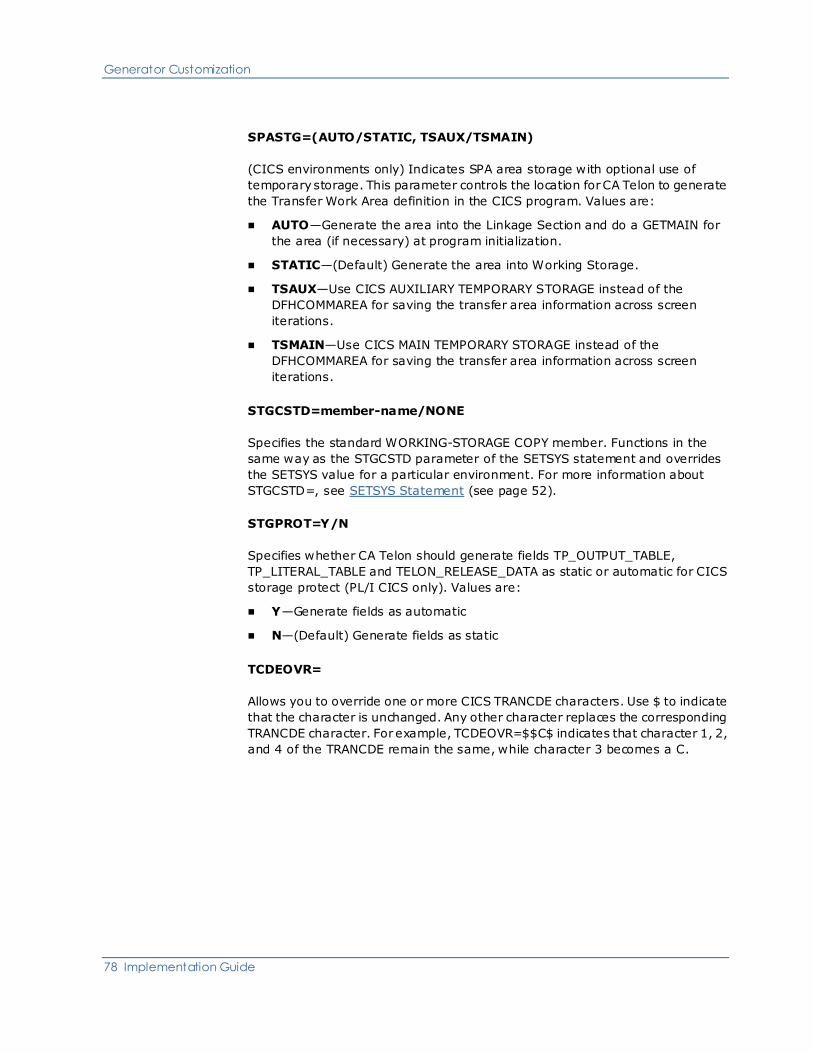
Generator Customization
78 Implementation Guide
SPASTG=(AUTO/STATIC, TSAUX/TSMAIN)
(CICS environments only) Indicates SPA area storage with optional use of
temporary storage. This parameter controls the location for CA Telon to generate
the Transfer Work Area definition in the CICS program. Values are:
■ AUTO—Generate the area into the Linkage Section and do a GETMAIN for
the area (if necessary) at program initialization.
■ STATIC—(Default) Generate the area into Working Storage.
■ TSAUX—Use CICS AUXILIARY TEMPORARY STORAGE instead of the
DFHCOMMAREA for saving the transfer area information across screen
iterations.
■ TSMAIN—Use CICS MAIN TEMPORARY STORAGE instead of the
DFHCOMMAREA for saving the transfer area information across screen
iterations.
STGCSTD=member-name/NONE
Specifies the standard WORKING-STORAGE COPY member. Functions in the
same way as the STGCSTD parameter of the SETSYS statement and overrides
the SETSYS value for a particular environment. For more information about
STGCSTD=, see SETSYS Statement (see page 52).
STGPROT=Y/N
Specifies whether CA Telon should generate fields TP_OUTPUT_TABLE,
TP_LITERAL_TABLE and TELON_RELEASE_DATA as static or automatic for CICS
storage protect (PL/I CICS only). Values are:
■ Y—Generate fields as automatic
■ N—(Default) Generate fields as static
TCDEOVR=
Allows you to override one or more CICS TRANCDE characters. Use $ to indicate
that the character is unchanged. Any other character replaces the corresponding
TRANCDE character. For example, TCDEOVR=$$C$ indicates that character 1, 2,
and 4 of the TRANCDE remain the same, while character 3 becomes a C.

Generator Customization
Chapter 2: Basic Procedures 79
TMPHOLD=Y/N
Indicates whether to generate a TEMP-HOLD-AREA and related MOVEs for
COBOL programs using CICS TS Queue for the HOLD area. The
TEMP-HOLD-AREA is needed on the PC since successive 01 levels are not
necessarily contiguous in memory. The TEMP-HOLD-AREA is not required in
mainframe programs. Values are:
■ Y—Generate the TEMP-HOLD-AREA
■ N—(Default) Do not generate the TEMP-HOLD-AREA
TPBSTG=AUTO/STATIC
(CICS environments only) Specifies teleprocessing buffer storage. This
parameter controls where CA Telon generates the TP-BUFFER storage in a CICS
program. Values are:
■ AUTO—Generate the area into the Linkage Section and do a GETMAIN at
program initialization
■ STATIC—(Default) Generate the area into Working Storage
TPICHK=Y/N
Indicates whether a check for blanks occurs prior to a move for ALPHA FLDTYPE.
Values are:
■ Y—(Default) Check for blanks prior to move for ALPHA FLDTYPE
■ N—Do not check for blanks prior to move for ALPHA FLDTYPE
TRACE=Y/N
Indicates whether the system generates program trace logic. Values are:
■ Y—(Default) Yes
■ N—No
WNDWLNK=Y/N
Indicates whether the WORK-WINDOW-YEAR created by use of the WNDWYR
parameter. Field should be created in LINKAGE or working STORAGE. Values
are:
■ N—(Default) Generate WORK-WINDOW-YEAR in LINKAGE.
■ Y—Generate WORK-WINDOW-YEAR in working storage.

Generator Customization
80 Implementation Guide
WNDWYR=yy
Specifies the cutoff date for dates in thee 20th versus 21st centuries. Used for CA
Telon-supplied windowing date fields such as IWDATE and OWJULIAN (all
environments). Any number less than the window year is considered to be in the
21st; any number greater or equal is considered to be in the 20th century.
Values are 00-99. There is no default.
XFRCSTD=member-name/NONE
Specifies the standard transfer area copy member. This parameter functions in
the same way as the XFRCSTD parameter of the SETSYS statement and
overrides the SETSYS value for a particular environment. See the discussion of
the XFRCSTD= parameter in SETSYS Statement (see page 52).
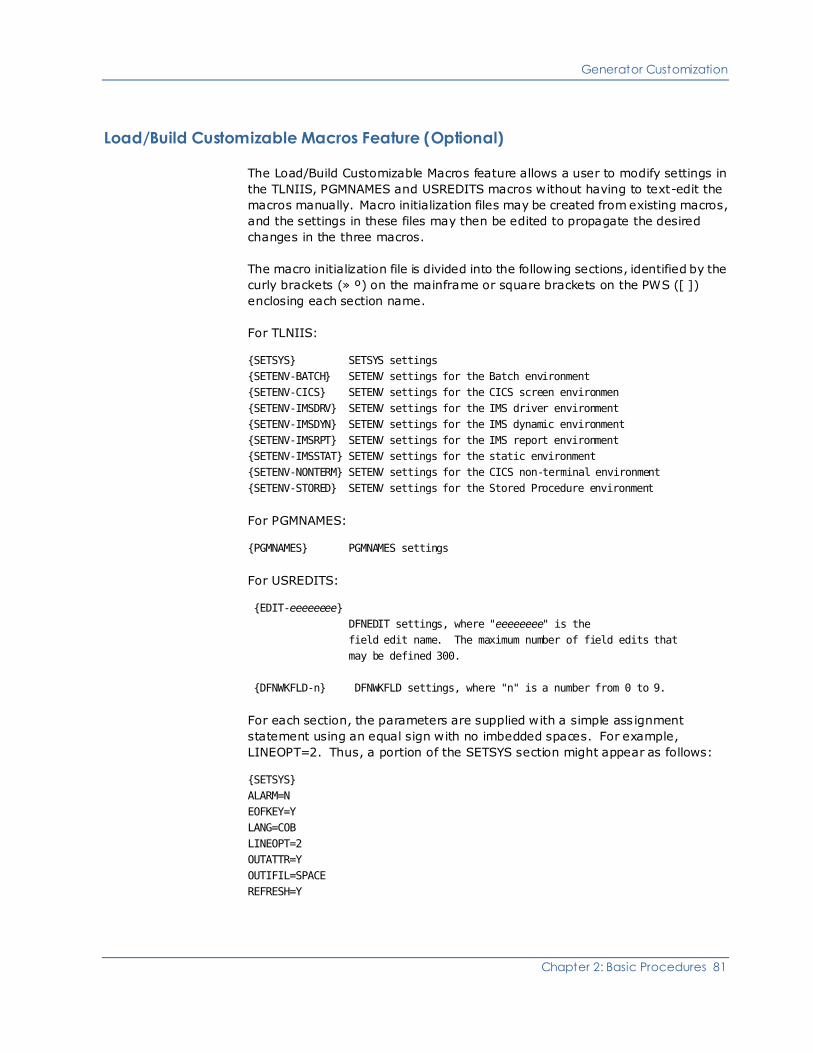
Generator Customization
Chapter 2: Basic Procedures 81
Load/Build Customizable Macros Feature (Optional)
The Load/Build Customizable Macros feature allows a user to modify settings in
the TLNIIS, PGMNAMES and USREDITS macros without having to text-edit the
macros manually. Macro initialization files may be created from existing macros,
and the settings in these files may then be edited to propagate the desired
changes in the three macros.
The macro initialization file is divided into the following sections, identified by the
curly brackets (» º) on the mainframe or square brackets on the PWS ([ ])
enclosing each section name.
For TLNIIS:
{SETSYS} SETSYS settings
{SETENV-BATCH} SETENV settings for the Batch environment
{SETENV-CICS} SETENV settings for the CICS screen environmen
{SETENV-IMSDRV} SETENV settings for the IMS driver environment
{SETENV-IMSDYN} SETENV settings for the IMS dynamic environment
{SETENV-IMSRPT} SETENV settings for the IMS report environment
{SETENV-IMSSTAT} SETENV settings for the static environment
{SETENV-NONTERM} SETENV settings for the CICS non-terminal environment
{SETENV-STORED} SETENV settings for the Stored Procedure environment
For PGMNAMES:
{PGMNAMES} PGMNAMES settings
For USREDITS:
{EDIT-eeeeeeee}
DFNEDIT settings, where "eeeeeeee" is the
field edit name. The maximum number of field edits that
may be defined 300.
{DFNWKFLD-n} DFNWKFLD settings, where "n" is a number from 0 to 9.
For each section, the parameters are supplied with a simple ass ignment
statement using an equal sign with no imbedded spaces. For example,
LINEOPT=2. Thus, a portion of the SETSYS section might appear as follows:
{SETSYS}
ALARM=N
EOFKEY=Y
LANG=COB
LINEOPT=2
OUTATTR=Y
OUTIFIL=SPACE
REFRESH=Y

Generator Customization
82 Implementation Guide
PLI/O PGMNAMES Parameters
To distinguish them from the COBOL settings, the parameter names in the macro
initialization file for the PL/I HEADER settings begin with a "Q" rather than a "P".
In the actual macro, these parameters appear with a "P" as the firs t byte. The
names of the COBOL and the PL/I parameters are listed in the following chart.
COBOL Name PL/I Name Description
PGMBHDR QGMBHDR PROGRAM HEADER
BATCH
PGMTHDR QGMTHDR PROGRAM HEADER TSO
TEST
PGMIHDR QGMIHDR PROGRAM HEADER IMS
DYNAMIC PROGRAM
PGMDHDR QGMDHDR PROGRAM HEADER IMS
DRIVER
PGMSHDR QGMSHDR PROGRAM HEADER IMS
STATIC
PGMLHDR QGMLHDR PROGRAM HEADER IMS
ALIAS
PGCPHDR QGCPHDR PROGRAM HEADER CICS
PGCCHDR n/a PROGRAM HEADER CICS
CLIENT
PGCSHDR n/a PROGRAM HEADER CICS
SERVER
PGNPHDR QGNPHDR PROGRAM HEADER CICS
NONTERM
PGSPHDR QGSPHDR PROGRAM HEADER
STORED PROCEDURE
PGMBHDL QGMPHDL PROGRAM HEADER
LENGTH BATCH
PGMTHDL QGMTHDL PROGRAM HEADER
LENGTH TSO
PGMIHDL QGMIHDL PROGRAM HEADER
LENGTH IMS DYNAMIC
PGMDHDL QGMDHDL PROGRAM HEADER
LENGTH IMS DRIVER
PGMSHDL QGMSHDL PROGRAM HEADER
LENGTH IMS STATIC

Generator Customization
Chapter 2: Basic Procedures 83
COBOL Name PL/I Name Description
PGMLHDL QGMLHDL PROGRAM HEADER
LENGTH IMS ALIAS
PGCPHDL QGCPHDL PROGRAM HEADER
LENGTH CICS
PGCCHDL n/a PROGRAM HEADER
LENGTH CICS CLIENT
PGCSHDL n/a PROGRAM HEADER
LENGTH CICS SERVER
PGNPHDL QGNPHDL PROGRAM HEADER
LENGTH CICS NONTERM
PGSPHDR QGSPHDR PROGRAM HEADER
STORED PROCEDURE
PGSPHDL QGSPHDL PROGRAM HEADER
LENGTH STORED
PROCEDURE
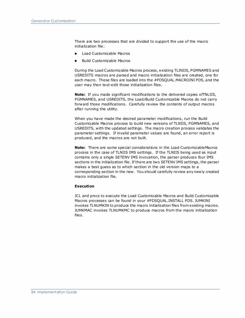
Generator Customization
84 Implementation Guide
There are two processes that are divided to support the use of the macro
initialization file:
■ Load Customizable Macros
■ Build Customizable Macros
During the Load Customizable Macros process, existing TLINIIS, PGMNAMES and
USREDITS macros are parsed and macro initialization files are created, one for
each macro. These files are loaded into the #PDSQUAL.MACROINI PDS, and the
user may then text-edit those initialization files.
Note: If you made significant modifications to the delivered copies ofTNLIIS,
PGMNAMES, and USREDITS, the Load/Build Customizable Macros do not carry
forward those modifications. Carefully review the contents of output macros
after running the utility.
When you have made the desired parameter modifications, run the Build
Customizable Macros process to build new versions of TLNIIS, PGMNAMES, and
USREDITS, with the updated settings. The macro creation process validates the
parameter settings. If invalid parameter values are found, an error report is
produced, and the macros are not built.
Note: There are some special considerations in the Load CustomizableMacros
process in the case of TLNIIS IMS settings. If the TLNIIS being used as input
contains only a single SETENV IMS invocation, the parser produces four IMS
sections in the initialization file. If there are two SETENV IMS settings, the parser
makes a best guess as to which section in the old version maps to a
corresponding section in the new. You should carefully review any newly created
macro initialization file.
Execution
JCL and procs to execute the Load Customizable Macros and Build Customizable
Macros processes can be found in your #PDSQUAL.INSTALL PDS. JUMKINI
invokes TLNUMKIN to produce the macro initialization files from existing macros.
JUMKMAC invokes TLNUMKMC to produce macros from the macro initialization
files.

Further Customization of Macro Libraries
Chapter 2: Basic Procedures 85
Further Customization of Macro Libraries
The CA Telon Generator macro library used in your running system is referred to
as MACLIB.
This discussion provides additional customization information to consider for the
following members of this data set: TELONIIS, TLNIIS, and PGMNAMES, which
you can use to:
■ Define your naming conventions for generated programs
■ Define your installation's environment
These environment and naming conventions were set to initial defaults during
your product installation.
By maintaining multiple versions of TLNIIS and PGMNAMES or multiple versions
of MACLIB, you can provide different applications groups with:
■ Differing security
■ Differing naming conventions
■ Differing system or environment defaults
■ Isolation from other groups

Further Customization of Macro Libraries
86 Implementation Guide
Security
It is not unusual for different application groups to have very different standard
processing requirements. For example, to verify that the operator is authorized
to execute a requested function, one system may require that a security module
be called with every execution of the generated programs. A second system may
only require transaction level security.
The security for the second system can be handled at the transaction level with
existing system software. But transaction level security is not sufficient for the
first system. That system requires a functional security that is executed at the
beginning of every program.
This functional security, in the form of custom code, can be generated separately
into every program. An easier way to do this is with the PGMCSTD parameter set
in TLNIIS, you can tell the CA Telon Generator to include code at a particular
point in every generated program.
PGMCUST must be authorized (for example, specified) in SETENV in MACLIB
member TLNIIS for any program to use an exit name in the PGMCUST
parameter. See TLNIIS member SETENV for BATCH in the CA Telon Training
source (SOURCEC or SOURCEP) library for an example.
PGMCSTD tells the Generator to insert code into specific points of the program.
Its format is shown next:
PGMCSTD=(exit-name1,member-name1[,exit-namen,member-namen ]....)
where:
■ Exit-name is any of the exit point names described in the following list
■ Member-name is a user-defined custom code member to be inserted at this
point
The next table identifies the valid exit point names and their respective
functions.
Note: An I at the end of an exit name indicates that the code is inserted at the
beginning of the section. A T at the end indicates the code is inserted at the end
of the section.
Exit name Function
MAINI To include custom code at the
beginning of the program mainline
MAINLINE To replace the program mainline of an
SD, DR, or RD with custom code When
this is coded the CA Telon Generator

Further Customization of Macro Libraries
Chapter 2: Basic Procedures 87
Exit name Function
does not create a standard mainline
MAINT To include custom code at the end of
the program mainline
MAININPUTI To include custom code at the
beginning of the MAIN-INPUT section
of an SD generated program
MAININPUTT To include custom code at the end of
the MAIN-INPUT section of an SD
program
MAINOUTPUTI To include custom code at the
beginning of the MAIN-OUPUT section
of an SD program
MAINOUTPUTT To include custom code at the end of
the MAIN-OUTPUT section of an SD
program
MAINPROCESSI To includce custom code at the
beginning of the MAIN-PROCESS
section of the program
MAINPROCESST To include custom code at the end of
the MAIN-PROCESS section of the
program
section-idI To include custom code at the
beginning of Section section-id *
section-idT To include custom code at the end of
the Section section-id *
SRTINPUTLOOP Replaces MAINOUTPUTI for batch
mainline sort programs
SRTOUTPUTLOOP Replaces MAINOUTPUTT for batch
mainline sort programs

Further Customization of Macro Libraries
88 Implementation Guide
* section is the section/procedure letter/number combination identifying a
procedural portion of the generated program. For example:
A100T
Refers to custom code to be put on the end of section A-100
OUTPUT-INITIALIZATION
C1000I
Refers to custom code to be put at the beginning of section
C-1000-GET-TRANSACTION
Multiple TLNIIS Members
Returning to the differing security needs example, the first system would profit
from having the Generator use the PGMCSTD parameter. In this way, custom
code could always be inserted into the generated code to perform the security
check or to call a security module. However, the second system does not need
this generated security code.
So how would a single shop be able to meet these seemingly contradictory
needs? One way would be to set up and use more than one version of the TLNIIS
macro. The TELONIIS macro would also have to be modified in order to call the
appropriate version of TLNIIS. In this way, you can modify TLNIIS to the specific
needs of the application group using it.
For example, suppose the second system above, the one with transaction-level
security requirements would be the norm at your installation. Furthermore,
suppose you want to use PGMCSTD with the first system. How could you meet
these differing needs? You could create a second TLNIIS in MACLIB and name it
TLNIIShh, where hh is the header used by the application group needing the
extra security. You would then modify this TLNIIShh to use PGMCSTD to include
the security code.
To implement this TLNIIS, you would modify the following TELONIIS by
removing ** and changing the 'hh' to the application Header of the group
desiring the security. You would find and change these lines:
** AIF ('&SHEADER'. EQ 'hh').HDRhh
HDRhh ANOP
** TLNIIShh &CALLER.
When you had finished, the hh would be replaced with your application header
and the two occurrences of ** would be removed.
You would also need to update each specific customized TLNIIS member by
setting the appropriate member name within it. If you do not, you receive the
following Generator error messages:
IEV126 *** ERROR *** LIBRARY MACRO NAME INCORRECT ── MACRO - TLNISTR

Further Customization of Macro Libraries
Chapter 2: Basic Procedures 89
IEV057 *** ERROR *** UNDEFINED OPCODE ── TELON/TLNIISTR.
For example, if you change TELONIIS to call TLNIISTR, you must then create the
TLNIISTR macro. You also need to change the second line in your macro from:
TLNIIS &CALLER.
to
TLNIISTR &CALLER.
Include Standard Copy Members
To include a standard copy member at the beginning of working storage in
generated programs, use the STGCSTD parameter in either the SETSYS or
SETENV statements of TLNIIS.
Naming Conventions
Naming convention differences between applications can be treated in the same
manner as security differences. For example, naming convention differences
can occur when one group wants three-byte headers while another wants
two-byte headers.
When you have naming convention differences, create new versions of the
TLNIIS and PGMNAMES macros. Name the new TLNIIS as described in the prior
example (TLNIIShh) and assign PGMNAMES any name other than PGMNAMES.
For example, suppose you have customized your naming conventions in
PGMNAMES but want to keep the delivered naming conventions for training (the
Header is TR). You can accomplish this with the following steps:
1. Copy TLNIIS to TLNIISTR, leaving both in the MACLIB data set (on the
mainframe) or directory (on PWS)
2. Modify TLNIISTR to call PGMNAMTR instead of PGMNAMES
3. Copy PGMNAMED (the default names member) to PGMNAMTR, leaving both
in MACLIB
4. Modify TELONIIS as outlined above so that it calls TLNIISTR when
'&SHEADER'. is TR
Further Customization of Macro Libraries
90 Implementation Guide
System Default Differences
Like the PGMCSTD parameter of TLNIIS, you can maintain separate versions of
TLNIIS with differing SETSYS and SETENV parameters to specify differing
environments, such as:
■ An environment to be used when you are testing out the new program
■ An environment reflecting the needs of a production version of the program
in one installation
■ An environment reflecting the needs of a different production installation
Multiple TELONIIS members
To maintain production defaults that are different from your test system defaults
requires more than simply using different versions of TLNIIS. This is because
there is no difference in the headers to indicate to TELONIIS which version of
TLNIIS to call.
In this situation, you would need to create a second MACLIB PDS and place only
the differing versions of TELONIIS, TLNIIS, and PGMNAMES into this new
MACLIB. When you wanted to use these macros, you would use the TESTMAC
parameter of the Generator procedures to point to this new MACLIB.
Maintenance
If you modify TELONIIS, TLNIIS, and PGMNAMES to suit your needs, you are
responsible for maintaining and upgrading any TELONIIS, TLNIIS, or PGMNAMES
macros that you create. When you receive a new release or Service Pack of CA
Telon, you are responsible for determining its impact on your versions of
TELONIIS, TLNIIS, and PGMNAMES. To help you, the release or Service Pack fix
list describes the changes that affect these macros and all other changes.
We recommend that any new MACLIB data sets you create contain only the
TELONIIS, TLNIIS, and PGMNAMES macros. The standard CA Telon macro
library should contain all the unmodified macros.

Implementation Tips
Chapter 2: Basic Procedures 91
Implementation Tips
Consider the following when implementing CA Telon:
■ You may choose to limit the scope of a view to project-pertinent data.
■ After your project has been completed, export all CA Telon source from the
TDF and put it through your normal change control process. You are not
required to keep the generated COBOL or PL/I code, but you must keep the
CA Telon source.
■ Let CA Telon generate as much code as possible. Custom code takes longer
to maintain. Have a thorough knowledge of the CA Telon program structure
charts so that you understand how much custom code is really needed and
the best place in the program to use it.
Terminate a Program Abnormally
CA Telon provides standard routines for terminating a program abnormally.
Whenever an I/O function is performed, CA Telon checks the return code. If an
unexpected status is returned, abnormal termination is performed.
CA Telon provides four types of abnormal termination, that can be accessed by
setting the ABNORMALT parameter in TLNIIS to 0, 1, 2, or 3. Setting the
ABNORMALT parameter to 0 eliminates any abnormal termination handling and
is not recommended.
Before r2, the only way to terminate a program abnormally was either calling
ADGADBER or ADGDBER in IMS/DC or using an EXEC CICS ABEND in CICS.
CA Telon still provides these methods through the SETENV FEATURE
ABNORMALT 1 in your MACLIB PDS member TLNIIS. As of r2, CA Telon provides
an alternate method of terminating a program abnormally by means of the
SETENV FEATURE ABNORMALT 2.
Abnormal Termination Feature 1
Functional description
CA Telon provides two standard ABEND routines (ADGADBER for COBOL and
ADGDBER for PL/I) for processing unexpected error conditions such as an AI
status code on a DL/I read.
These routines allow a program to:

Terminate a Program Abnormally
92 Implementation Guide
■ Perform DL/I database backout and recovery when an error has been
detected
■ Prohibit further processing
Processing options
TSO and IMS programs call the ABEND routine, but processing differs between
the two cases based on the value of the PROGRAM TYPE field (T for TSO or Test
mode, P for IMS or Production mode).
If PROGRAM TYPE is P, the routine passes control to a user written exit called
ADUABNC for COBOL and ADUABNP for PL/I. A skeleton version of these
routines is provided in pdsqual.SOURCE.
As delivered, these routines use only the first value in the parameter list and
issue incremental user ABENDs. CA recommends that you modify these user
exits to interface to your own standard IMS ABEND routine.
Interface requirements
A parameter list is passed to the ABEND routine that contains items that the user
exits may use. This parameter list is for user exit processing only. The default
routines do not use this list. The parameters are listed in the following tables and
described on the pages immediately after the tables.
COBOL / PL/I
Name
Length Description
1 PROGRAM-TYPE
PROGRAM-TYPE-SU
FFIX
routine-ABEND-CO
DE
1
13
2
T (TEST) P
(Production)
Release level,
program name
Binary ABEND
code
2 TRACE SECTION
NAME
8 Current program
section
3 IO PCB 40 IO-PCB
4 ABEND PCB 12 Either the
XFER-PCB or a
TPPCB generated
with ABCALL=Y
5 SPA AREA V SPA-AREA

Terminate a Program Abnormally
Chapter 2: Basic Procedures 93
Parameters 6 - 9 vary depending on the type of abend. Those variations are
described in the following tables.
DB Errors
The parameters are the first three parameters passed in the database call in
error.
COBOL / PL/I Name Length
6 DL/I Function Code 4
7 Database PCB V
8 Segment I/O Area V
Invalid NEXT-PROGRAM-NAME
The parameters are as follows:
COBOL / PL/I
Name
Length Description
6 XFER-ABEND-CODE 4 Set to XFER
7 NEXT-PROGRAM-N
AME
8 Containing invalid
program name
Dynamic links that fail
The parameters are as follows:
COBOL / PL/I
Name
Length Description
6 XFER-ABEND-CODE 4 Set to XFER
7 NEXT-PROGRAM-N
AME
8 Containing invalid
program name
8 ALIAS-PROGRAM-N
AME
8 Containing alias
name used for the
dynamic load
9 WORKFLD-NUMERI
C
18
14
COB
PLI
Containing ABEND
code converted

Terminate a Program Abnormally
94 Implementation Guide
COBOL / PL/I
Name
Length Description
from hex to
decimal.
The most common
ABENDS are:
■ 262— System
ABEND 106
■ 1798—
System ABEND
706
■ 2051—
System ABEND
80
Non-matching SPA Sizes
The parameters are:
COBOL / PL/I
Name
Length Description
6 SPASIZE-ABEND-C
ODE
8 Set to SPASIZE
7 WORKFLD-NUMERI
C
18
14
COB
PLI
Containing the
length of the SPA
received from IMS

Terminate a Program Abnormally
Chapter 2: Basic Procedures 95
Parameter Descriptions
A description of each parameter is provided next.
Parameter 1
The first parameter consists of three concatenated fields:
■ PROGRAM-TYPE has a value of T for TSO programs and P for IMS
programs.
■ PROGRAM-TYPE-SUFFIX is a 12-byte character string that is generated
after PROGRAM TYPE and has the following format:
frrrnnnnnnnn
where:
– f is the literal X'FF' to indicate r1.2 format
– rrr is the literal containing the CA Telon Release level
– nnnnnnnn is the program name
■ routine ABEND-CODE is a two-byte binary value that passes an ABEND
code to the user ABEND exit. The ABEND CODE routine is named
ADGADBER-ABEND-CODE for COBOL and ADGDBER-ABEND-CODE for PL/I
programs. ABEND-CODE identifies each ABEND call within a program by a
unique ABEND number. The number passed is based upon the value of the
ABENDST parameter on the SETENV statement in member TLNIIS set at
installation time.
The ABENDST parameter specifies the ABEND code to be passed to the first
generated call to the ABEND routines in a program. If ABENDST is set to 0,
CA Telon passes the value of 98 to all calls.
If the parameter is non-zero, CA Telon generates a move statement with the
value of ABENDST for the first generated call and increments it by 1 for each
successive generated call. This assists greatly in identifying where in the
program the ABEND routine was called.
IMS has reserved ABEND codes 3500 through 4094 for client ABEND codes.
ABENDST as delivered has a value of 3500. If you want to pass ABEND codes
in your Custom Code, CA recommends that you start with 4000 so that all
ABEND codes issued are unique in the program.
Note: The supplied user exit routines, ADUABNC and ADUABNP, issue an
ABEND using the value in this field.

Terminate a Program Abnormally
96 Implementation Guide
Parameter 2
TRACE SECTION NAME contains the section name if the program includes the
generated trace logic. The TRACE parameter of the IMSPGM/IMSDRV statement
requests this logic. The default value for the TRACE parameter is set on the
SETENV statement in member TLNIIS at installation time. If the trace logic is not
included in the program, this parameter still exists, but the value does not
contain valid information.
Parameter 3
The IO PCB is the primary IMS/DC communication PCB between the application
program, the terminal, and the message queue. It is the first parameter
supplied to all application programs, and you can use it to respond to the
terminal operator.
Parameter 4
ABEND PCB is a user-controlled PCB. To send messages from the ABEND
routines, it is necessary to use an alternate PCB that specifies EXPRESS=YES.
The default PCB passed is the XFER PCB. CA Telon uses this PCB primarily for
message switching, which requires EXPRESS=NO for conversational systems.
If you need to specify EXPRESS=NO on the XFER PCB, and want to write a
message from your user exit, you can pass a PCB that specifies EXPRESS=YES to
the ABEND routines to do this, code a TPPCB statement with ABCALL=Y and
EXPRESS=Y. The generated calls pass this PCB to the ABEND routines. If you do
not code TPPCB with ABCALL, the XFER PCB is passed.
IMS Abnormal Termination 1 Example
* GENERATED SEGMENT VALIDATION EDIT LISTCHK
MOVE WS-START-BROWSE-KEY TO TRGEMPL-SSA-VALUE.
MOVE '<=' TO TRGEMPL-SSA-OPCODE.
MOVE 'TRGEMPL ' TO TRACE-SEGMENT-NAME.
CALL 'CBLTDLI' USING GN-FUNC
EMPLOYEE-PCB
IOA-TRGEMPL-SEGMENT
TRGEMPL-SSA.
MOVE EMPLOYEE-STATUS-CODE TO DA-STATUS-DLI
EMPLOYEE-TRGEMPL-STATUS.

Terminate a Program Abnormally
Chapter 2: Basic Procedures 97
PERFORM U-100-SET-DA-STATUS-DLI.
IF EMPLOYEE-STATUS-CODE NOT = SPACES
AND EMPLOYEE-TRGEMPL-1 NOT = 'G'
MOVE 3500 TO ADGADBER-ABEND-CODE
CALL 'ADGADBER' USING PROGRAM-TYPE
TRACE-SECTION-NAME
IO-PCB
ABEND-PCB
SPA-AREA
GN-FUNC
EMPLOYEE-PCB
IOA-TRGEMPL-SEGMENT.
MOVE '=' TO TRGEMPL-SSA-OPCODE.
IF EMPLOYEE-STATUS-CODE NOT = SPACES
MOVE DO-WRITE-LIT TO CONTROL-INDICATOR
MOVE ERROR-ATTR TO TPO-STARTBR-ATTR
MOVE '*** REQUESTED LIST IS EMPTY ***' TO TPO-ERRMSG1
GO TO J-100-SELECT-RETURN.
MOVE WS-START-BROWSE-KEY TO XFER-EMPL-ID.
MOVE PROCESS-OUTPUT-LIT TO CONTROL-INDICATOR
ENTRY-CONTROL-INDICATOR.
* SELECT/SCONSIS NOT CODED
*
* SELECT/NEXTPGM
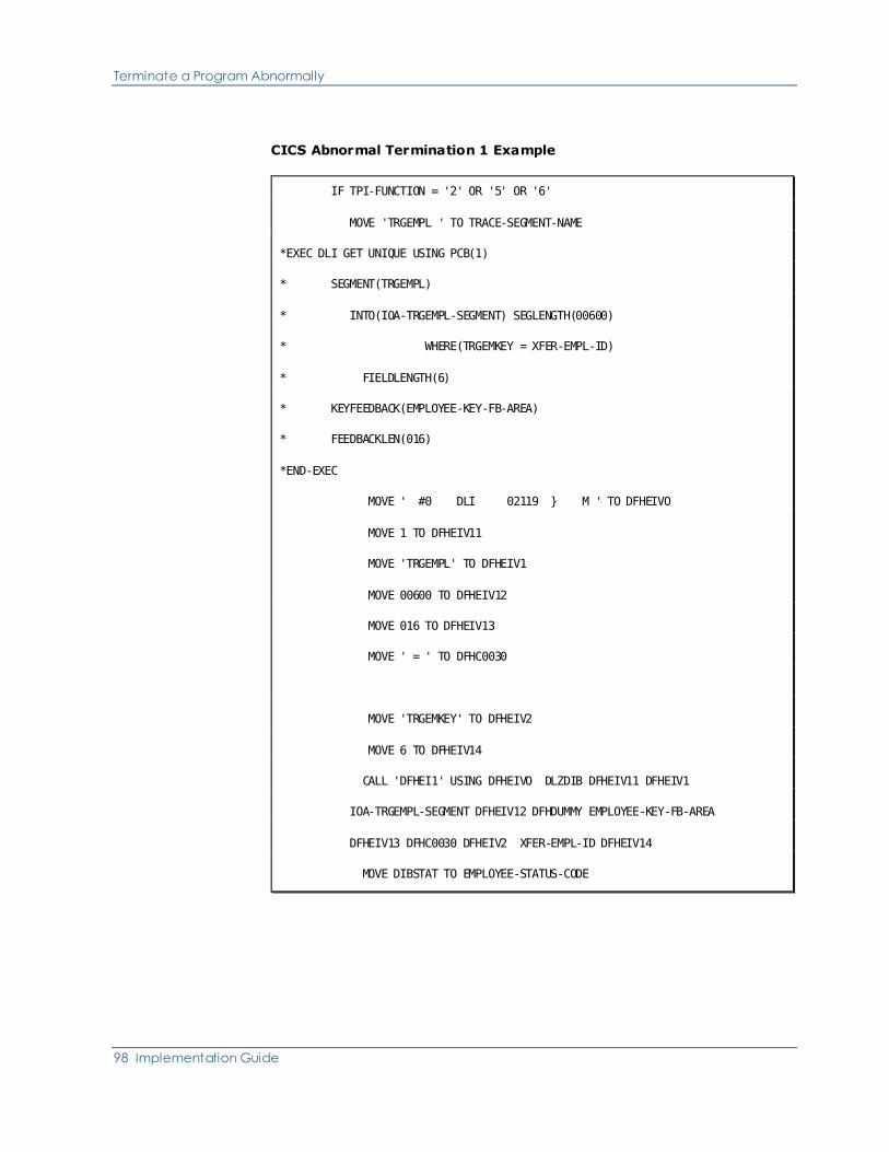
Terminate a Program Abnormally
98 Implementation Guide
CICS Abnormal Termination 1 Example
IF TPI-FUNCTION = '2' OR '5' OR '6'
MOVE 'TRGEMPL ' TO TRACE-SEGMENT-NAME
*EXEC DLI GET UNIQUE USING PCB(1)
* SEGMENT(TRGEMPL)
* INTO(IOA-TRGEMPL-SEGMENT) SEGLENGTH(00600)
* WHERE(TRGEMKEY = XFER-EMPL-ID)
* FIELDLENGTH(6)
* KEYFEEDBACK(EMPLOYEE-KEY-FB-AREA)
* FEEDBACKLEN(016)
*END-EXEC
MOVE ' #0 DLI 02119 } M ' TO DFHEIVO
MOVE 1 TO DFHEIV11
MOVE 'TRGEMPL' TO DFHEIV1
MOVE 00600 TO DFHEIV12
MOVE 016 TO DFHEIV13
MOVE ' = ' TO DFHC0030
MOVE 'TRGEMKEY' TO DFHEIV2
MOVE 6 TO DFHEIV14
CALL 'DFHEI1' USING DFHEIVO DLZDIB DFHEIV11 DFHEIV1
IOA-TRGEMPL-SEGMENT DFHEIV12 DFHDUMMY EMPLOYEE-KEY-FB-AREA
DFHEIV13 DFHC0030 DFHEIV2 XFER-EMPL-ID DFHEIV14
MOVE DIBSTAT TO EMPLOYEE-STATUS-CODE

Terminate a Program Abnormally
Chapter 2: Basic Procedures 99
MOVE 'GHU' TO XDLI-FUNC
MOVE EMPLOYEE-STATUS-CODE TO DA-STATUS-DLI
EMPLOYEE-TRGEMPL-STATUS
PERFORM U-100-SET-DA-STATUS-DLI
IF EMPLOYEE-STATUS-CODE NOT = SPACES
AND EMPLOYEE-TRGEMPL-1 NOT = 'G'
*EXEC CICS ABEND ABCODE('TLND') END-EXEC
MOVE ' - 02135 ' TO DFHEIV0
MOVE 'TLND' TO DFHEIV5
CALL 'DFHEI1' USING DFHEIV0 DFHEIV5
ELSE IF EMPLOYEE-STATUS-CODE = SPACES
MOVE DO-WRITE-LIT TO CONTROL-INDICATOR
MOVE ERROR-ATTR TO TPO-FUNCTION-ATTR TPO-ID-ATTR
MOVE '*** EMPLOYEE DOES EXIST ***' TO TPO-ERRMSG1
GO TO X-100-CONSIS-EDITS-RETURN.
Abnormal Termination Feature 2
An abnormal termination situation arises in a CA Telon application when an
"unexpected" event occurs. Examples of these are:
■ TP environment has not been specified correctly
■ DBMS responds with an unforeseen status code
■ Next screen to be presented to the user is unavailable
CA Telon provides a standard method of handling these situations. Remember
when an abnormal situation occurs, it is important in an online environment
that:
■ Any database activity be backed out
■ Further processing be prevented
■ This is accomplished by the user tailoring the ABT (ADxxABT) routine.
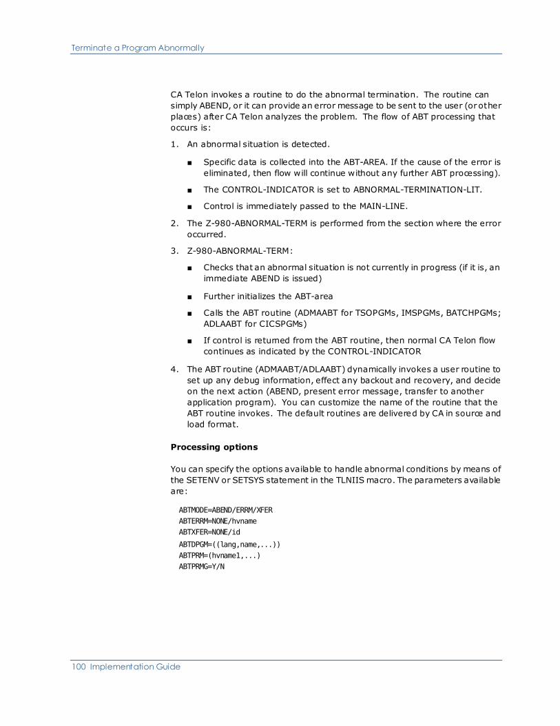
Terminate a Program Abnormally
100 Implementation Guide
CA Telon invokes a routine to do the abnormal termination. The routine can
simply ABEND, or it can provide an error message to be sent to the user (or other
places) after CA Telon analyzes the problem. The flow of ABT processing that
occurs is:
1. An abnormal situation is detected.
■ Specific data is collected into the ABT-AREA. If the cause of the error is
eliminated, then flow will continue without any further ABT processing).
■ The CONTROL-INDICATOR is set to ABNORMAL-TERMINATION-LIT.
■ Control is immediately passed to the MAIN-LINE.
2. The Z-980-ABNORMAL-TERM is performed from the section where the error
occurred.
3. Z-980-ABNORMAL-TERM:
■ Checks that an abnormal situation is not currently in progress (if it is, an
immediate ABEND is issued)
■ Further initializes the ABT-area
■ Calls the ABT routine (ADMAABT for TSOPGMs, IMSPGMs, BATCHPGMs;
ADLAABT for CICSPGMs)
■ If control is returned from the ABT routine, then normal CA Telon flow
continues as indicated by the CONTROL-INDICATOR
4. The ABT routine (ADMAABT/ADLAABT) dynamically invokes a user routine to
set up any debug information, effect any backout and recovery, and decide
on the next action (ABEND, present error message, transfer to another
application program). You can customize the name of the routine that the
ABT routine invokes. The default routines are delivered by CA in source and
load format.
Processing options
You can specify the options available to handle abnormal conditions by means of
the SETENV or SETSYS statement in the TLNIIS macro. The parameters available
are:
ABTMODE=ABEND/ERRM/XFER
ABTERRM=NONE/hvname
ABTXFER=NONE/id
ABTDPGM=((lang,name,...))
ABTPRM=(hvname1,...)
ABTPRMG=Y/N

Terminate a Program Abnormally
Chapter 2: Basic Procedures 101
In abnormal situations, the first decision to be made is: "What should the user
see when the situation occurs?" You have the following options:
1. To ABEND and let the system handle the user, specify:
ABTMODE=ABEND
2. To present an error message on the current screen, specify:
ABTMODE=ERRM
ABTERRM=hvname
where hvname is the host variable name
3. To transfer to a "standard" screen that "explains" the situation, and the
actions that are available, specify:
ABTMODE=XFER
ABTXFER=id
If options 2 or 3 are chosen then the second decision to be made is "What
information should be returned?" CA Telon sets up a standard area (ABT-AREA
described next) of information about the problem and passes this to the ABT
routine along with other areas that may be involved in the problem. These
standard parameters are described next.
Generally, the areas allow the ABT routines to present a standard message to the
user. Furthermore, the installation has the option to add additional parameters
or substitute a completely different set of parameters. This is done by using
SETENV or SETSYS parameter ABTPRM to list the parameters to be passed to the
ABT routine.
If ABTPRMG=Y is specified then the ABTPRM list is added to the standard
parameter list. If ABTPRMG=N is specified then the ABTPRM list replaces the
standard parameter list.
The use of additional parameters or the need for tailoring the messages or the
process requires you to modify or replace subroutines that ADMAABT/ADLAABT
dynamically invokes. Customers often do this type of customization and that is
why the source code for all ABT routines is delivered with the product in
pdsqual.source. The routines that customers most commonly modify are:
Environment COBOL Routine PL/I Routine
TSO ADTCABT ADTPABT
IMS ADICABT ADIPABT
CICS ADCCABT ADCPABT
BATCH ADBCABT ADBPABT
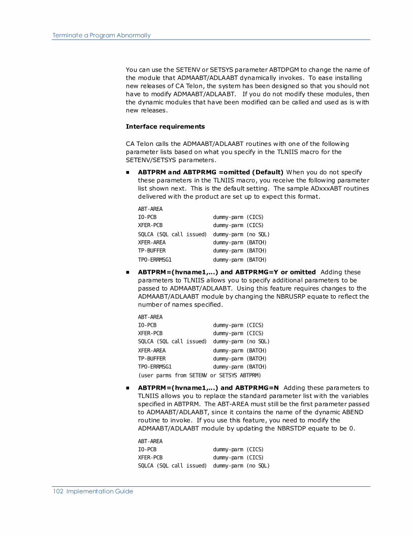
Terminate a Program Abnormally
102 Implementation Guide
You can use the SETENV or SETSYS parameter ABTDPGM to change the name of
the module that ADMAABT/ADLAABT dynamically invokes. To ease installing
new releases of CA Telon, the system has been designed so that you should not
have to modify ADMAABT/ADLAABT. If you do not modify these modules, then
the dynamic modules that have been modified can be called and used as is with
new releases.
Interface requirements
CA Telon calls the ADMAABT/ADLAABT routines with one of the following
parameter lists based on what you specify in the TLNIIS macro for the
SETENV/SETSYS parameters.
■ ABTPRM and ABTPRMG =omitted (Default) When you do not specify
these parameters in the TLNIIS macro, you receive the following parameter
list shown next. This is the default setting. The sample ADxxxABT routines
delivered with the product are set up to expect this format.
ABT-AREA
IO-PCB dummy-parm (CICS)
XFER-PCB dummy-parm (CICS)
SQLCA (SQL call issued) dummy-parm (no SQL)
XFER-AREA dummy-parm (BATCH)
TP-BUFFER dummy-parm (BATCH)
TPO-ERRMSG1 dummy-parm (BATCH)
■ ABTPRM=(hvname1,...) and ABTPRMG=Y or omitted Adding these
parameters to TLNIIS allows you to specify additional parameters to be
passed to ADMAABT/ADLAABT. Using this feature requires changes to the
ADMAABT/ADLAABT module by changing the NBRUSRP equate to reflect the
number of names specified.
ABT-AREA
IO-PCB dummy-parm (CICS)
XFER-PCB dummy-parm (CICS)
SQLCA (SQL call issued) dummy-parm (no SQL)
XFER-AREA dummy-parm (BATCH)
TP-BUFFER dummy-parm (BATCH)
TPO-ERRMSG1 dummy-parm (BATCH)
(user parms from SETENV or SETSYS ABTPRM)
■ ABTPRM=(hvname1,...) and ABTPRMG=N Adding these parameters to
TLNIIS allows you to replace the standard parameter list with the variables
specified in ABTPRM. The ABT-AREA must still be the first parameter passed
to ADMAABT/ADLAABT, since it contains the name of the dynamic ABEND
routine to invoke. If you use this feature, you need to modify the
ADMAABT/ADLAABT module by updating the NBRSTDP equate to be 0.
ABT-AREA
IO-PCB dummy-parm (CICS)
XFER-PCB dummy-parm (CICS)
SQLCA (SQL call issued) dummy-parm (no SQL)

Terminate a Program Abnormally
Chapter 2: Basic Procedures 103
XFER-AREA dummy-parm (BATCH)
TP-BUFFER dummy-parm (BATCH)
TPO-ERRMSG1 dummy-parm (BATCH)
(user parms from SETENV or SETSYS ABTPRM)
The ABT area contains the following information:
■ Error function
■ Name of dynamic routine
■ Program type
■ Program name
■ CA Telon ABEND code
■ Control indicator
■ DBMS-specific information
This area is documented in detail in each of the dynamically-invoked subroutines
(ADxxABT), in the SOURCE PDS data set.
Note: If your installation is running an RDBMS, uncomment the references
marked '<DB2>' in the following source members and recompile:
ADBCABT ADIPABT
ADBPABT ADTCABT
ADICABT ADTPABT
CA Telon passes additional environment and/or DBMS-specific information to the
ADxxABT routines. They are captured in the ABT-AREA or by the calls to
ADMAAB0/ADMAAB1/ADLAAB0/ADLAAB1 (alternate entry points to
ADMAABT/ADLAABT).
Parameters saved by the alternate entry points are appended to the parameter
list passed to ADMAABT/ADLAABT. These additional parameters do not have to
be accepted by the ADxxABT routines.
If you do not want to use them, simply remove them as parameters in the
ADxxABT routines. A maximum of 17 additional parameters are possible. The
environment or DBMS-specific information passed is:
Environment DBMS Parameters
TSO DL/I ■ Call function code
■ Call PCB
■ Call IO area
■ Call SSAs

Terminate a Program Abnormally
104 Implementation Guide
Environment DBMS Parameters
DB2 ■ SQLCA
■ Call function code
■ Call IO area
IMS/DC All ■ IO PCB
ABEND PCB
DL/I ■ Call function code
■ Call PCB
■ Call IO area
■ Call SSAs
Any RDBMS ■ SQLCA
■ Call function code
■ Call IO area
CICS VSAM ■ Call function
■ Call data set name
■ Call IO area
DL/I ■ Call function code
■ Call PCB
■ Call IO area
■ Call SSAs
Any RDBMS ■ SQLCA
■ Call function mode
■ Call IO area
BATCH VSAM ■ Call function
■ Call data set name
■ Call IO area
DL/I ■ Call function code
■ Call PCB
■ Call IO area
■ Call SSAs
Any RDBMS ■ SQLCA
■ Call function code

Terminate a Program Abnormally
Chapter 2: Basic Procedures 105
Environment DBMS Parameters
■ Call IO area
Note: Most of the abnormal termination functionality described above does not
apply to stored procedures.
This list is documented in detail in each of the dynamically-invoked subroutines,
(ADxAATR) in the SOURCE data set.

Terminate a Program Abnormally
106 Implementation Guide
Save Parameters example
The next example shows Abnormal Termination 2. This termination saves
parameters from a previous I/O.
IF TPI-FUNCTION = '2' OR '5' OR '6'
MOVE 'TRGEMPL ' TO TRACE-SEGMENT-NAME
*EXEC DLI GET UNIQUE USING PCB(1)
* SEGMENT(TRGEMPL)
* INTO(IOA-TRGEMPL-SEGMENT) SEGLENGTH(00600)
* WHERE(TRGEMKEY = XFER-EMPL-ID)
* FIELDLENGTH(6)
* KEYFEEDBACK(EMPLOYEE-KEY-FB-AREA)
* FEEDBACKLEN(016)
*END-EXEC
MOVE ' #0 DLI 02238 } M ' TO DFHEIV0
MOVE 1 TO DFHEIV11
MOVE 'TRGEMPL' TO DFHEIV1
MOVE 00600 TO DFHEIV12
MOVE 016 TO DFHEIV13
MOVE ' = ' TO DFHC0030
MOVE 'TRGEMKEY' TO DFHEIV2
MOVE 6 TO DFHEIV14
CALL 'DFHEI1' USING DFHEIV0 DLZDIB DFHEIV11 DFHEIV1
IOA-TRGEMPL-SEGMENT DFHEIV12 DFHDUMMY EMPLOYEE-KEY-FB-AREA
DFHEIV13 DFHC0030 DFHEIV2 XFER-EMPL-ID DFHEIV14
MOVE DIBSTAT TO EMPLOYEE-STATUS-CODE
MOVE 'GHU' TO XDLI-FUNC
MOVE EMPLOYEE-STATUS-CODE TO DA-STATUS-DLI

Terminate a Program Abnormally
Chapter 2: Basic Procedures 107
EMPLOYEE-TRGEMPL-STATUS
PERFORM U-100-SET-DA-STATUS-DLI
IF EMPLOYEE-STATUS-CODE NOT = SPACES
AND EMPLOYEE-TRGEMPL-1 NOT = 'G'
MOVE 3500 TO ABT-ERROR-ABEND-CODE
MOVE XDLI-FUNC TO ABT-DA-FUNCTION
MOVE 'DB ' TO ABT-DA-FUNC-PCB-TYPE
MOVE 'XDLI' TO ABT-ERROR-ACTIVITY
MOVE 'TRGEMPL ' TO ABT-DA-ACCESS-NAME
CALL 'ADLAAB0'
PERFORM Z-980-ABNORMAL-TERM
ELSE IF EMPLOYEE-STATUS-CODE = SPACES
MOVE DO-WRITE-LIT TO CONTROL-INDICATOR
MOVE ERROR-ATTR TO TPO-FUNCTION-ATTR TPO-ID-ATT
MOVE '*** EMPLOYEE DOES EXIST ***' TO TPO-ERRMSG1
ADLAABT example
The following example shows an Abnormal Termination 2 call to ADLAABT.
MOVE 'Y' TO ABT-IN-PROGRESS
ELSE
*EXEC CICS ABEND ABCODE('TABT') END-EXEC.
MOVE ' - 02359 ' TO DFHEIV0
MOVE 'TABT' TO DFHEIV5
CALL 'DFHEI1' USING DFHEIV0 DFHEIV5
MOVE TRACE-SECTION-NAME TO ABT-PROGRAM-FUNCTION
MOVE SPACE TO ABT-U100-SUB.
IF ABT-ERROR-SECTION-NAME = 'U-100'

Terminate a Program Abnormally
108 Implementation Guide
MOVE ABT-ERROR-SECTION-SUB TO ABT-U100-SUB
IF SEC-INDEX GREATER +1
MOVE SECTION-NAME-TABLE(SEC-INDEX - 1) TO
ABT-PROGRAM-FUNCTION.
MOVE DA-STATUS TO ABT-DA-GENERIC-STATUS.
MOVE SPACES TO ABT-ERROR-MESSAGE.
MOVE ' ' TO ABT NEXT PROGRAM NAME ID.
*******************************************************************
* NOTE: ADDITIONAL PARAMETER ADDRESSES HAVE BEEN "PASSED" *
* TO ADLAABT BY USE OF ITS ENTRY POINTS ADLAAB0 *
* AND ADLAAB1 *
*******************************************************************
CALL 'ADLAABT' USING ABNORMAL-TERMINATION-AREA
IO-PCB
XFER-PCB
ABNORMAL-TERMINATION-AREA
SPA-XFER-WORK-AREA
TP-BUFFER
TPO-ERRMSG1.
IF ABT-DO-WRITE
MOVE ABT-ERROR-MESSAGE TO TPO-ERRMSG1
MOVE DO-WRITE-LIT TO CONTROL-INDICATOR
SET SEC-INDEX TO 1
PERFORM N-100-CURSOR-POSITION
TRCPCCEM 9.09.17 JUL 28,2001
GO TO MAIN-PROCESS-RETURN
ELSE

Terminate a Program Abnormally
Chapter 2: Basic Procedures 109
IF ABT-DO-TRANSFER
Abnormal Termination Feature 3
Abnormal Termination Feature 3 is the 31-bit reentrant version of Abnormal
Termination for CA Telon. The reentrant versions of the interface modules are
ADMAATR in the TSO, IMS, MVS Batch environments and ADLAATR in the CICS
environment.
Functionally, Abnormal Termination 3 works exactly like Abnormal Termination 2
with a few exceptions, as described next.
Exceptions for IMS and MVS Batch
CA Telon calls an entry point ADMAATX in the interface routine before COBOL
GOBACKs and PLI RETURNS. This entry point frees up the parameter capture
area used by the entry points ADMAAT0 and ADMAAT1.
ADMAATR works in a similar manner to ADLAATR, but it uses GETMAIN and
FREEMAIN macros rather than CICS macros to establish and release reentrant
storage. The entry points for ADMAATR are:
Entry Point Description
ADMAAT0 Captures non-DL/I parameters.
ADMAAT1 Captures the DL/I parameter list.
ADMAATX Establishes addressability to the
parameter list and ABP storage
ADMAATR Uses the GETMAIN macro to obtain
storage below the 16M line. This
storage is used as working storage for
the ABT interface program. ADMAATR
then:
1. Sets up the save area chain and
uses a GETMAIN to obtain storage
below the line for the ABP area.
2. Determines if you are running under
XA. If you are not under XA, ADMAATR
passes control to the appropriate
Dynamic Program. If you are running
under XA, ADMAATR may call
ADRALAR (which is the linkage assist

Terminate a Program Abnormally
110 Implementation Guide
Entry Point Description
routine) before giving control to the
Dynamic Program.
ADRALAR performs a series of tests
before passing control to the Dynamic
Program. ADRALAR checks to see if:
■ The program is loaded above the
line. If it is, ADRALAR issues
ABEND U4010 and produces a
dump.
■ The parameter list is loaded above
the line. If it is, ADRALAR issues
ABEND U4011 and produces a
dump.
Only one of the parameters in the
parameter list is loaded above the line.
In this case, ADRALAR issues ABEND
U4012 and produces a dump
Exceptions for CICS
CA Telon calls entry points ADLAATI and ADLAATX to initialize and free the
parameter capture area used by the entry points ADLAAT0, ADLAAT1, and
ADLAAT2.
Release 2.1 added entry point ADLAAT2 to capture the DL/I parameter list
(including the parameter count parm) after EXEC DLI calls. This differs from
Abnormal Termination Feature 2 in that Feature 2 captures the parameters from
the last token call to the EXEC DLI interface.
The dynamically-invoked interface routine can now treat error situations from
EXEC DLI calls as standard DL/I calls that take into account that the first
parameter received is the fullword parameter count field.
An abnormal termination situation arises in a CA Telon application when an
unexpected event occurs. Examples of these are the:
■ TP environment has not been specified correctly
■ DBMS responds with an unforeseen status code
■ Next screen to be presented to the user is unavailable
CA Telon provides a standard method of handling these situations. Remember
that when an abnormal situation occurs, it is important in an online environment
that:
■ Any database activity be backed out
Terminate a Program Abnormally
Chapter 2: Basic Procedures 111
■ Further processing be prevented
This is accomplished by the user tailoring the ABT (ADxxABT) routine.
CA Telon invokes a routine to do the abnormal termination. The routine can
simply ABEND, or it can provide an error message to be sent to the user (or other
places) after CA Telon analyzes the problem. The flow of ABT processing that
occurs is:
1. An abnormal situation is detected.
■ Specific data is collected into the ABT-AREA
■ The CONTROL-INDICATOR is set to ABNORMAL-TERMINATION-LIT.
■ Control is immediately passed to the MAIN-LINE.
2. The Z-980-ABNORMAL-TERM is performed from the section where the error
occurred.
3. Z-980-ABNORMAL-TERM:
■ Checks that an abnormal situation is not currently in progress (if it is, an
immediate ABEND is issued)
■ Further initializes the ABT-area
■ Calls the ABT routine (ADMAATR for TSOPGMs, IMSPGMs, BATCHPGMs;
ADLAATR for CICSPGMs)
■ If control is returned from the ABT routine, then normal CA Telon flow
continues as indicated by the CONTROL-INDICATOR
4. The ABT routine (ADMAATR/ADLAATR) dynamically invokes a user routine to
set up any debug information, effect any backout and recovery, and decide
on the next action (ABEND, present error message, transfer to another
application program). You can customize the name of the routine that the
ABT routine invokes. The default routines are delivered by CA in source and
load format.
Processing options
You can specify the options available to handle abnormal conditions by means of
the SETENV or SETSYS statement in the TLNIIS macro. The parameters available
are:
ABTMODE=ABEND/ERRM:XFER
ABTERRM=NONE/hvname
ABTXFER=NONE/id
ABTDPGM=((lang,name,...))
ABTPRM=(hvname1,...)

Terminate a Program Abnormally
112 Implementation Guide
ABTPRMG=Y/N
In abnormal situations, the first decision to be made is "What should the user see
when the situation occurs?" You have the following options:
1. To ABEND and let the system handle the user, specify:
ABTMODE=ABEND
2. To present an error message on the current screen, specify:
ABTMODE=ERRM
ABTERRM=hvname
where hvname is the host variable name
3. To transfer to a "standard" screen that "explains" the situation and the
actions that are available, specify:
ABTMODE=XFER
ABTXFER=id
If options 2 or 3 above are chosen then the second decision to be made is "What
information should be returned?" CA Telon sets up a standard area (ABT-AREA
described next) of information about the problem and passes this to the ABT
routine along with other areas that may be involved in the problem. These
standard parameters are described next.
Generally, the areas allow the ABT routines to present standard message to the
user. Furthermore, the installation has the option to add additional parameters
or substitute a completely different set of parameters. This is done by using
SETENV or SETSYS parameter ABTPRM to list the parameters to be passed to the
ABT routine.
If ABTPRMG=Y is specified then the ABTPRM list is added to the standard
parameter list. If ABTPRMG=N is specified then the ABTPRM list will replace the
standard parameter list.
The use of additional parameters or the need for tailoring the messages or the
process requires you to modify or replace subroutines that ADMAATR/ADLAATR
dynamically invokes. Customers often do this type of customization and that is
why the source code for all ABT routines is delivered with the product. The
routines that customers modify most commonly are listed in the next table.
Environment COBOL Routine PL/I Routine
TSO ADTCABT ADTPABT
IMS ADICABT ADIPABT
CICS ADCCABT ADCPABT
BATCH ADBCABT ADBPABT

Terminate a Program Abnormally
Chapter 2: Basic Procedures 113
Note: Most of the abnormal termination functionality described abovedoes not
apply to stored procedures.
You can use the SETENV or SETSYS parameter ABTDPGM to change the name of
the module that ADMAATR/ADLAATR dynamically invokes. To ease installing new
releases of CA Telon, the system has been designed so that you should not have
to modify ADMAATR/ADLAATR. If you do not modify these modules, then the
dynamic modules that have been modified can be called and used as is with new
releases.
CA Telon calls the ADMAATR/ADLAATR routines with one of the following
parameter lists based on what you specify in the TLNIIS macro for the
SETENV/SETSYS parameters.
■ ABTPRM and ABTPRMG omitted (Default) When you do not specify
these parameters in the TLNIIS macro, you receive the following parameter
list. This is the default setting. The sample ADxxxABT routines delivered
with the product are set up to expect this format.
ABT-AREA
IO-PCB dummy-parm (CICS)
XFER-PCB dummy-parm (CICS)
SQLCA (SQL call issued) dummy-parm (no SQL)
XFER-AREA dummy-parm (BATCH)
TP-BUFFER dummy-parm (BATCH)
TPO-ERRMSG1 dummy-parm (BATCH)
■ ABTPRM=(hvname1,...) and ABTPRMG=Y or omitted Adding these
parameters to TLNIIS allows you to specify additional parameters to be
passed to ADMAABT/ADLAABT. Using this feature requires changes to the
ADMAABT/ADLAABT module by changing the NBRUSRP equate to reflect the
number of names specified.
ABT-AREA
IO-PCB dummy-parm (CICS)
XFER-PCB dummy-parm (CICS)
SQLCA (SQL call issued) dummy-parm (no SQL)
XFER-AREA dummy-parm (BATCH)
TP-BUFFER dummy-parm (BATCH)
TPO-ERRMSG1 dummy-parm (BATCH)
(user parms from SETENV or SETSYS ABTPRM)
■ ABTPRM=(hvname1,...) and ABTPRMG=N Adding these parameters to
TLNIIS allows you to replace the standard parameter list with the variables
specified in ABTPRM. The ABT-AREA must still be the first parameter passed
to ADMAABT/ADLAABT, since it contains the name of the dynamic ABEND
routine to invoke. If you use this feature, you need to modify the
ADMAABT/ADLAABT module by updating the NBRSTDP equate to be 0.

Terminate a Program Abnormally
114 Implementation Guide
ABT-AREA
IO-PCB dummy-parm (CICS)
XFER-PCB dummy-parm (CICS)
SQLCA (SQL call issued) dummy-parm (no SQL)
XFER-AREA dummy-parm (BATCH)
TP-BUFFER dummy-parm (BATCH)
TPO-ERRMSG1 dummy-parm (BATCH)
(user parms from SETENV or SETSYS ABTPRM)
The ABT area contains the following information:
■ Error function
■ Name of dynamic routine
■ Program type
■ Program name
■ CA Telon ABEND code
■ Control indicator
■ DBMS-specific information
This area is documented in detail in each of the dynamically-invoked subroutines
(ADxxABT), in the SOURCE data set.
Note: If your installation is running DB2, uncomment the references marked
'<DB2>' in the following source members and recompile:
ADBCABT ADIPABT
ADBPABT ADTCABT
ADICABT ADTPABT
CA Telon passes additional environment and/or DBMS-specific information to the
ADxxATR routines. They are captured in the ABT-AREA or by the calls to
ADMAAB0/ADMAAB1/ADLAAB0/ADLAAB1 (alternate entry points to
ADMAATR/ADLAATR).
Parameters saved by the alternate entry points are appended to the parameter
list passed to ADMAATR/ADLAATR. These additional parameters do not have to
be accepted by the ADxxATR routines.
If you do not want to use them, simply remove them as parameters in the
ADxxATR routines. A maximum of 17 additional parameters are possible. The
environment and/or DBMS-specific information passed is:
Environment DBMS Parameters
TSO DL/I ■ Call function code
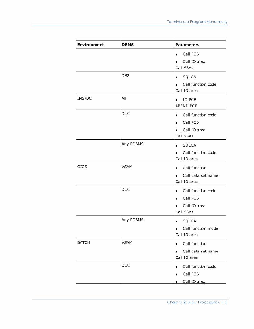
Terminate a Program Abnormally
Chapter 2: Basic Procedures 115
Environment DBMS Parameters
■ Call PCB
■ Call IO area
Call SSAs
DB2 ■ SQLCA
■ Call function code
Call IO area
IMS/DC All ■ IO PCB
ABEND PCB
DL/I ■ Call function code
■ Call PCB
■ Call IO area
Call SSAs
Any RDBMS ■ SQLCA
■ Call function code
Call IO area
CICS VSAM ■ Call function
■ Call data set name
Call IO area
DL/I ■ Call function code
■ Call PCB
■ Call IO area
Call SSAs
Any RDBMS ■ SQLCA
■ Call function mode
Call IO area
BATCH VSAM ■ Call function
■ Call data set name
Call IO area
DL/I ■ Call function code
■ Call PCB
■ Call IO area

Terminate a Program Abnormally
116 Implementation Guide
Environment DBMS Parameters
■ Call SSAs
Any RDBMS ■ SQLCA
■ Call function code
■ Call IO area
Note: Most of the abnormal termination functionality described above does not
apply to stored procedures.
This list is documented in detail in each of the dynamically-invoked subroutines,
(ADxAATR) in the SOURCE data set.
ADLAAT2 Abnormal Termination 3 Example
The next example shows an ADLAAT2 call to capture EXEC DLI parameters in
Abnormal Termination 3.
IF TPI-FUNCTION = '2' OR '5' OR '6'
MOVE 'TRGEMPL ' TO TRACE-SEGMENT-NAME
*EXEC DLI GET UNIQUE USING PCB(1)
* SEGMENT(TRGEMPL)
* INTO(IOA-TRGEMPL-SEGMENT) SEGLENGTH(00600)
* WHERE(TRGEMKEY = XFER-EMPL-ID)
* FIELDLENGTH(6)
* KEYFEEDBACK(EMPLOYEE-KEY-FB-AREA)
* FEEDBACKLEN(016)
*END-EXEC
MOVE ' #0 DLI 02241 } M ' TO DFHEIV0
MOVE 1 TO DFHEIV11
MOVE 'TRGEMPL' TO DFHEIV1
MOVE 00600 TO DFHEIV12
MOVE 016 TO DFHEIV13
MOVE ' = ' TO DFHC0030
MOVE 'TRGEMKEY' TO DFHEIV2
MOVE 6 TO DFHEIV14
CALL 'DFHEI1' USING DFHEIV0 DLZDIB DFHEIV11 DFHEIV1
IOA-TRGEMPL-SEGMENT DFHEIV12 DFHDUMMY EMPLOYEE-KEY-FB-AREA
DFHEIV13 DFHC0030 DFHEIV2 XFER-EMPL-ID DFHEIV14
MOVE DIBSTAT TO EMPLOYEE-STATUS-CODE
MOVE 'GHU' TO XDLI-FUNC
MOVE EMPLOYEE-STATUS-CODE TO DA-STATUS-DLI
EMPLOYEE-TRGEMPL-STATUS
PERFORM U-100-SET-DA-STATUS-DLI
IF EMPLOYEE-STATUS-CODE NOT = SPACES
AND EMPLOYEE-TRGEMPL-1 NOT = 'G'

Terminate a Program Abnormally
Chapter 2: Basic Procedures 117
MOVE 3500 TO ABT-ERROR-ABEND-CODE
MOVE XDLI-FUNC TO ABT-DA-FUNCTION
MOVE 'DB ' TO ABT-DA-FUNC-PCB-TYPE
MOVE 'XDLI' TO ABT-ERROR-ACTIVITY
MOVE 'TRGEMPL ' TO ABT-DA-ACCESS-NAME
CALL 'ADLAAT2'
PERFORM Z-980-ABNORMAL-TERM
ELSE IF EMPLOYEE-STATUS-CODE = SPACES
MOVE DO-WRITE-LIT TO CONTROL-INDICATOR
MOVE ERROR-ATTR TO TPO-FUNCTION-ATTR TPO-ID-ATTR
MOVE '*** EMPLOYEE DOES EXIST ***' TO TPO-ERRMSG1
ADLAATR example
The next example shows an ADLAATR call to perform ABEND processing.
* NOTE: ADDITIONAL PARAMETER ADDRESSES HAVE BEEN "PASSED" TO
*
* ADLAATR BY USE OF ITS ENTRY POINTS ADLAAT0 ADLAAT1
*
* AND ADLAAT2
*
************************************************************************
CALL 'ADLAATR' USING DFHEIBLK
DFHCOMMAREA
ABNORMAL-TERMINATION-AREA
IO-PCB
XFER-PCB
ABNORMAL-TERMINATION-AREA
SPA-XFER-WORK-AREA
TP-BUFFER
TPO-ERRMSG1.
IF ABT-DO-WRITE
MOVE ABT-ERROR-MESSAGE TO TPO-ERRMSG1
MOVE DO-WRITE-LIT TO CONTROL-INDICATOR
TRCPCCEM 12.27.47 JUL 28,2005
SET SEC-INDEX TO 1
PERFORM N-100-CURSOR-POSITION
GO TO MAIN-PROCESS-RETURN
ELSE
IF ABT-DO-TRANSFER
MOVE ABT-NEXT-PROGRAM-NAME TO NEXT-PROGRAM-NAME
MOVE DO-TRANSFER-LIT TO CONTROL-INDICATOR
SET SEC-INDEX TO 1
GO TO MAIN-PROCESS-RETURN

Terminate a Program Abnormally
118 Implementation Guide
ELSE
IF ABT-CONTINUE-PROCESS
MOVE 'N' TO ABT-IN-PROGRESS
ELSE
*EXEC CICS ABEND ABCODE('TABT') END-EXEC.
MOVE ' - 02406 ' TO DFHEIV0
MOVE 'TABT' TO DFHEIV5
CALL 'DFHEI1' USING DFHEIV0 DFHEIV5
Z-980-ABNORMAL-TERM-RETURN.
EXIT.
TRCPCCEM 12,27.47 JUL 28,2008
Z-990-PROGRAM-ERROR SECTION.
************************************************************************

Chapter 3: Manage the CA Telon Environment 119
Chapter 3: Manage the CA Telon
Environment
Suggestions on different ways to manage your CA Telon environment are
provided to assist you in tailoring your installation according to any special
needs. This chapter discusses how to:
■ Set up and maintain user-defined subroutine data sets
■ Maintain TDF VSAM data sets
■ Maintain multiple CA Telon VSAM data sets under TSO
■ Reorganize, clear, backup, restore, and verify the CA Telon VSAM data sets
■ For CICS shops, use the TDF in a CICS/VS Multiple Region Operation
environment
■ Review the product and project setup checklists for mainframe CA Telon
implementation
This section contains the following topics:
User-Defined Subroutines (see page 120)
TDF VSAM Data Set Maintenance (see page 121)
Multiple TDF VSAM Data Sets (see page 125)
Maintain TDF Help Screens (see page 127)
TDF and Multiple Region Operation (see page 132)
Product and Project Set-Up Checklist (see page 132)

User-Defined Subroutines
120 Implementation Guide
User-Defined Subroutines
During the installation of CA Telon, the data set USERSUBR might have been
allocated as an additional load library, designed to hold your compiled,
link-edited, and custom field-edit subroutines.
If not, you might want to allocate pdsqual.USERSUBR as a load library for your
site.
If you choose to store your custom field edits in a different load library, you must
change the USERSUBR parameter in the LKED step of all CA Telon generate,
compile, and link procs. (See the Installation guide for all PROC name
variations.) You can change the parameter using one of the following methods:
■ Manually change each PROC
■ Adjust members $010 and #CUSTCTL in the INSTALL PDS and run
#CUSTCTL (also located in INSTALL)
■ Use a parameter override in the job stream instead of changing the procs
manually
In each of these procedures, the parameter, USERSUBR, references the
USERSUBR PDS.

TDF VSAM Data Set Maintenance
Chapter 3: Manage the CA Telon Environment 121
TDF VSAM Data Set Maintenance
The CA Telon Design Facility (TDF) is made up of nine VSAM data sets:
■ Four permanent VSAM data sets for application development information:
– vsamqual.TNTDD holding:
– Session profile information
– Installation profile information
– Data administration information - DBD and PSB definitions
– vsamqual.TNTDF holding program, and panel (or report) information
maintained by TDF options 3, 4, 5 and 6, excluding custom code
– vsamqual.TNTCCL holding custom code, including presentation store
information maintained by TDF Option 6
– vsamqual.TNTDX holding SQL Table information
■ Three VSAM data sets holding data currently undergoing change. These are
temporary, work-in-progress files:
– vsamqual.TNTDDW holding the work-in-progress version of TNTDD and
TNTCCL
– vsamqual.TNTDFW holding the work-in-progress version of TNTDF
– vsamqual.TNTDXW holding the SQL work-in-progress version of TNTDX
■ vsamqual.TNHOLD the TDF Hold file to support split session processing
■ vsamqual.TNHELP the TDF Help message file
Note: TDF Data Sets can be accessed across systems and to do this VSAM
share options must be (4,4).

TDF VSAM Data Set Maintenance
122 Implementation Guide
Reorganization and Clearing
These data sets are maintained in groups as they are laid out above.
Permanent data sets
The first four VSAM data sets from the list above (TNTDD, TNTDF, TNTDX, and
TNTCCL) contain application definition information in TDF format. You should
reorganize these data sets nightly to improve TDF performance.
If you fail to reorganize these data sets often enough, "TLDxxx" error messages
will be output to the TDF. These messages can occur at any time and indicate
that these data sets must be reorganized immediately. These same messages
occur when the CA Telon TDF VSAM files run out of space. If you run out of
space, you must allocate more space by modifying INSTALL(CREPROD). As
delivered this reorganization job has the following space allocations:
■ TNTCCL - CYLINDERS(6 1)
■ TNTDD - CYLINDERS(3 1)
■ TNTDF - CYLINDERS(6 1)
■ TNTDX - CYLINDERS(3 1)
To reorganize these data sets:
1. Submit job stream pdsqual.INSTALL(JREORGDL). This deletes any
sequential, unloaded format TDF data left over from previous
reorganizations. If you fail to do this, the following JREORGPR JOB will end in
error "Duplicate Name on Direct Access File" in job step SYSBR14.
2. Submit job stream INSTALL(JREORGPR). This unloads these four VSAM data
sets into sequential format, deletes the four VSAM files, defines them, then
reloads them from the sequential file it just created. All condition codes
being zero indicates a successful completion of the job.
For more information on U901 abends, see the appendix "Mainframe TDF
Abends."
Work files
You should clear TNTDDW, TNTDFW, and TNTDXW every night. If that is not
possible, you must do so at least once a week to assure acceptable performance.
To clear these data sets, submit INSTALL(JREORGWK). This deletes, defines,
and reinitializes TNTDDW, TNTDFW and TNTDXW.

TDF VSAM Data Set Maintenance
Chapter 3: Manage the CA Telon Environment 123
Hold file
The TNHOLD VSAM data set has less interaction than the other CA Telon data
sets. As a result, you might not need to clear this data set as often as the others.
However, CA recommends that you incorporate this data set's reorganization
into a standard nightly or weekly job.
To clear the TNHOLD data set, submit INSTALL (JREORGHD). This deletes,
defines, and reinitializes TNHOLD.
Help file
The TNHELP data set generally is used for read-only processing. As such, you do
not have to do any clearing or reorganization maintenance on it.
See the topic, Maintaining TDF Help Screens, later in this chapter for information
about changing TNHELP.
Back Up TDF VSAM Data Sets
You can back up the TDF VSAM data sets using any standard VSAM backup
procedures you already have in place. We strongly recommend using your own
back-up procedures to back up your CA Telon data sets daily. This ensures
optimum recovery capability should an unexpected disaster occur.
If you are not familiar with creating and implementing data set backup
procedures, you might want to obtain assistance from your site's system
programmer. However, if you do not have such procedures to back up VSAM
data sets, CA Telon provides you with job streams, procedures, and control cards
to assist you.

TDF VSAM Data Set Maintenance
124 Implementation Guide
Verifying TDF VSAM Data Sets
If you have any question about the integrity of your TDF VSAM data sets, you can
run the job stream INSTALL(JVERFY). This job stream verifies a single TDF VSAM
data set. JVERFY has the following parameters:
Parameter Description
KEYLEN=10 / 13 / 18 / 32 Key length of the TDF VSAM file to be
verified. Values are:
■ 13 - TNHELP
■ 18 - TNTDD, TNTDDW, and
TNTCCL
■ 32 - TNTDX and TNTDXW
Note: In the event of U901 abends in
the TDF, we recommend that you run
the JVERFY job to look for bad or
missing blocks. For more information,
see Recommendations for Handling
U901 Abends in the appendix "Abends
with TDF on the Mainframe" or see the
Message Reference Guide. If this is the
case, rerun the VERIFY job, specifying
a KEYLEN value of:
KEYLEN = 'Key length value, DELETE'
The DELETE parameter deletes the bad
root.
OPTION=0 / 2 / 3 / 8 File option you want JVERFY to
process. Values are:
■ 2 - process a TNTDX or TNTDXW
file
■ 3 - process a TNHELP file
8 - process a TNTDD or TNTDDW
TDFFILE=vsamqual.filename Name of the TDF VSAM data set you
want to process. You must include the
high level VSAM qualifier.
TLNLOAD=lib-name Name of the CA Telon LOAD library.

Multiple TDF VSAM Data Sets
Chapter 3: Manage the CA Telon Environment 125
Once you have set these parameters, submit JVERFY. The output of the job looks
like the following:
DL/S Verify
Root Number of blocks Status
TRADDS.PD 1 OK
TRADDS.PI 1 OK
TRMENU.SD 1 OK
_______________________________________
Total Distinct Roots 596
Total Blocks 605
Total Roots with Bad Blocks 0
Total Missing Blocks 0
Total Invalid Block Numbers 0
Multiple TDF VSAM Data Sets
Maintaining separate sets of these VSAM data sets for use by different groups at
your installation allows you to:
■ Isolate application groups by data set so you can use RACF/ACF2 type
security
■ Maintain unique system defaults, like, setting TNTDF with differing export
format or programming language defaults
■ Optimize response time because:
– Each set of files are smaller so retrieval and updating time are improved
– There are fewer lockouts due to enqueue processing on control intervals
– The indexes are less fragmented due to lower volume

Multiple TDF VSAM Data Sets
126 Implementation Guide
Considerations
Before making your final decisions on which of these TDF data sets to duplicate,
consider the following points:
■ TNTDD, TNTDF, TNTCCL, TNTDX - Create one version per application since
they contain all permanent data for the application.
■ TNTDDW, TNTDFW, TNTDXW - Create one version per application. If
necessary, you can create one per group of applications provided you delete,
define, and repro on a nightly basis as outlined in this chapter under TDF
VSAM Data Set Maintenance.
■ TNHOLD - Generally one version of this file is sufficient for all application
groups. However, if your programmers frequently use the CA Telon TSO/PDF
or split screen holding, you can improve performance by maintaining
multiple versions of this file.
■ TNHELP - Maintain one version of this file for all application groups. Sharing
TNHELP files among different TDFs is not supported because TNHELP is an
input-output file that allows the TDF help messages to be customized.
Procedure
You can create multiple versions of the TDF VSAM data sets when you are using
the TDF under TSO. TDFs operating in different CICS regions can also refer to
different TDF VSAM data sets. To implement a new TDF VSAM data set,
complete the following steps:
■ Create a new high level qualifier (vsamqual) and copy the TDF VSAM data
sets you are duplicating into this new qualifier or customize member
CTDFVSAM in your INSTALL PDS to allocate empty files
■ Modify the CLISTs in one of the following ways:
– Create a separate set of INSTALL(CLISTS) with all the CLISTS in it
pointing to the appropriate TDF VSAM data sets
– Modify the existing @TDF CLIST so that it can accept input to control the
high level VSAM qualifier of the desired version of the TDF
■ For CICS, alter the start-up JCL or FCT data set names to point to the desired
TDF VSAM files.

Maintain TDF Help Screens
Chapter 3: Manage the CA Telon Environment 127
Monitoring
Whether you maintain one or several versions of the TDF VSAM data sets, you
must monitor their status regularly. To do this, submit the INSTALL(JULSTCAT)
job stream, which executes the IBM AMS LISTCAT utility on TNTDD, TNTDF,
TNTDX, and TNTCCL. This utility reports on file disposition. There are three
important items to note on both the data and the index portions of these files.
They are EXTENT NUMBER, SPLITS-CI, and SPLITS-CA:
■ EXTENT NUMBER - Ideally this number should be zero, but it must be set to
whatever is practical for your site. As this number rises, the performance of
the file decreases. Disk pack fragmentation can be partially responsible for
the size of this number. If this number is too high, reorganize the file to
allocate a larger data or index portion depending on which portion showed an
abnormally high number.
■ SPLITS-CI and SPLITS-CA - As these numbers increase, your performance
degrades. File reorganization should eliminate this problem.
If you follow the reorganization schedule recommended in this chapter under the
TDF VSAM Data Set Maintenance topic, you should not experience these extent,
CI, and CA file split file problems.
Maintain TDF Help Screens
The Help messages used by the TDF are stored in vsamqual.TNHELP. You can
maintain and change these messages in two ways: online interactively and
through a batch job stream. These allow you to modify your TDF Help messages
to suit the needs of your particular installation.

Maintain TDF Help Screens
128 Implementation Guide
Online Help Message Modifications
It is easy to modify the TDF Help messages from within the TDF. You must have
the TDF Install password in order to identify yourself to the TDF as having Install
authorization. Once you have the password, you can follow these steps to
update any help screen.
1. If you are not in the TDF, execute the appropriate CLIST to start it. For CICS
shops, you can execute the appropriate CICS transaction.
2. Type INSTALL on the command line of the TDF main menu.
3. When the TDF displays the Install Menu, enter the Install password in the
PASSWORD field after entering:
FUNCTION: UP
ITEM : IP
4. Press PF3 to return to the Main Menu. You are now authorized to update
Help messages for the remainder of this TDF session.
See the Installation guide for more information about the Install Menu
screen.
5. To modify a particular hHelp message, bring up the screen that requests that
message.
6. Enter the Help character in the field for a field level Help message and press
Enter or press the Help PFKEY (default is PF1) for a screen level Help
message.
7. When you are viewing the message you want to change, type UPDATE on
the Command line at the top of the Help message screen. Press Enter.
8. At this point the message is unprotected so that you can enter your changes
over the existing messages. The message key is displayed in the upper left
corner. The next example shows you the Help message screen for the
FUNCTION field on the TDF Main Menu in this unprotected state with the key
in the upper left corner.
EDIT ---- F100=1FUNCTIO MEMBER 001 OF 001 SIZE 000043 COL 01
COMMAND ===> SCROLL ===> CSR
****** ********************************* TOP OF DATA **********************
000001 TITLE=FUNCTIONS AVAILABLE FOR TELON DESIGN FACILITY
000002 SHORT=
000003 DESCR=FUNCTIONS AVAILABLE FOR TELON DESIGN FACILITY
000004 1 -- USER PROFILE MAINTENANCE allows the user to set definition defaults,

Maintain TDF Help Screens
Chapter 3: Manage the CA Telon Environment 129
000005 PFKEY usage during design, and session controls. You can directly
000006 access definition defaults by entering 1D, session controls by
000007 entering 1S, and PFKEYs by entering 1P.
000008
000009 2 -- DATA ADMINISTRATION allows the user to CREATE, UPDATE, PURGE,
000010 LIST, and SHOW data entities, including File Groups, PSB's, DBDs,
000011 SQL Tables and Joins, VSAM Files, Sequential Files, CICS Queues,
000012 and CICS Journals.
000013
000014 3 -- PANEL SPECIFICATION allows the user to CREATE, UPDATE, PURGE,
000015 LIST, and SHOW - IMAGES, PANELS, FIELDS, CONSISTENCY EDITS, and
000016 SEGLOOP data.
000018 4 -- ONLINE PROGRAM DEFINITION allows the user to CREATE, UPDATE, PURGE,
000019 PURGE, LIST, and SHOW the ITEMs requested by the user (SCREEN ,
000020 DRIVER, REPORT, NONTERMINAL, ENVIRONMENT, DATA GROUP, or CUSTOM
000021 CODE) under a specified HEADER and ID. (NOTE: 4N and 4S
000022 take you to the ONLINE PROGRAM DEFINITION menu.)
000023
000024
000025 5 -- BATCH PROGRAM DEFINITION allows the user to CREATE, UPDATE, PURGE,
000026 and SHOW the ITEM's requested by the user (BATCH, PANEL IMAGE,
000027 PANEL DEFINITION, ENVIRONMENT, DATA GROUP, CUSTOM CODE, and
000028 under specified HEADER and ID.
Note: Under ONLINE PROGRAM DEFINITION, LIST, PURGE, and SHOW are
not applicable to USER-IO.
Enter your changes, then press PF3 to save your message. The
vsamqual.TNHELP is updated by the TDF.
Maintain TDF Help Screens
130 Implementation Guide
Note: Seven pages (149 lines) is the maximum CA Telon allows for each
HELP message.
9. The TDF displays the message USER UPDATED to indicate that this particular
message has been changed. To protect your unique messages, the batch
update described next does not write over a help message tagged as USER
UPDATED.
10. If you have other messages to update, repeat Steps 5 through 10 until all
have been updated.
Batch Help Message Update
When you have several Help screens to update, you can use the batch job stream
INSTALL(JUHLOAD) to modify vsamqual.TNHELP. You can also use this job
when you have modified your Help messages. We issue updates to TNHELP for
new releases. The batch job has built-in functions to prevent overwriting USER
UPDATED messages.
As delivered, this job uses the contents of pdsqual.HELPUPDT to update
vsamqual.TNHELP. Edit messages in pdsqual.HELPUPDT and apply them by
running this job.
Batch update record format
The input file containing the actual Help message update records is by default
pdsqual.HELPUPDT. It is identified in the job with the DD name TNHLPIN.
There are two types of records in the input file: key and text. Both are
fixed-length, 80 bytes long.
■ The key record is used to identify the help message being created or
updated. It is broken down as follows:
Columns Description
1 - 8 Must be the characters HELPMSG=
9 - 21 Actual key of the Help message to be
updated with the following records. It
is the key that appears in the upper left
corner of the online update screen
22 - 80 Description of the message.

Maintain TDF Help Screens
Chapter 3: Manage the CA Telon Env ironment 131
■ The text record contains the help message text to be placed in the help
message identified by the key. You can only use columns 1 through 79
because an attribute byte is added to column one of each text line when the
message is displayed by the TDF.
Batch operation
To update the files by using the batch job stream, submit JUHLOAD and check
the messages printed in the SYSOUT data set. There are three possible
messages:
■ CA UPDATED HELP MSG ==> P100 SCREEN1
Indicates that the key matched an existing key and the Help message was
not flagged as USER UPDATED and TNPCHLOD updated TNHELP.
■ CLIENT UPDATED HELP MSG ==> F100NAFUNCTIO -REPLACE NOT
ATTEMPTED FOR THIS MSG
Indicates that the key matched an existing key and the Help message was
flagged as USER UPDATED. TNPCHLOD did not update TNHELP. You must
analyze this new message against your custom message and update your
message online if you want the new version.
■ CA ADDED HELP MSG ==> KD10 SCREEN1
Indicates the key did not match any record already in TNHELP. In this case,
the JUHLOAD batch job adds the message as a new Help screen.
Help screens for new product releases
When we release a new CA Telon product release, the help screens for TNHELP
are delivered with both an (vsamqual.VSAMINIT(TNHELP)), unloaded help file
that you can IDCAMS repro into your existing TNHELP file and as a HELPUPDT
file.
If you are an existing customer but have never updated your Help messages,
you can use the repro version and replace the entire TNHELP file with the
contents from VSAMQUAL.VSAMINIT(TNHELP) member. On the other hand, if
you do change your Help messages, use the HELPUPDT file along with JUHLOAD
to guarantee that you do not overlay custom messages you may have created.
Any USER UPDATED messages are not changed. This allows you to selectively
overwrite your own Help messages.

TDF and Multiple Region Operation
132 Implementation Guide
TDF and Multiple Region Operation
For CICS shops only
CICS/VS Multiple Region Operation (MRO) allows you to share resources and
terminals among CICS/VS regions located in the same processor.
MRO supports function shipping so that your applications can access resources
owned by other regions. These resources can be:
■ Files or DL/I databases
■ Temporary storage or a transient data queue
■ Another transaction through a start request
MRO also supports transaction routing, also known as terminal sharing. This
allows a terminal owned by one region to enter a transaction to be routed by a
CICS program to another CICS region for execution.
Product and Project Set-Up Checklist
A checklist is provided in this section of what you should verify before using CA
Telon to develop a project, and the types of data sets you would set up for a
typical project. See the Installation guide for a detailed checklist, including
many optional implementation steps, for installing the CA Telon product.

Product and Project Set-Up Checklist
Chapter 3: Manage the CA Telon Environment 133
Checklist
1. Allocate project-specific data sets using the training system data sets as a
guide for space and DCB Information. Use the following data sets as an
example of what you will create for a typical project.
■ SOURCE— Used to store CA Telon source code for your project. (Do not
confuse this with the source library created during the product
installation.) CA Telon source is created by a CA Telon export. CA Telon
source is used as input to the CA Telon generator.
■ COPYLIB— Used to store copybook definitions defined externally to CA
Telon and which will be used in your CA Telon programs.
■ DBDLIB— Used to store DBD source code in an IMS/DB environment.
(You can use existing DBDLIBs here.)
■ PSBLIB— Used to store user-defined or CA Telon-generated PSB source
code.
■ PROCPDS— Where CA Telon JCL and PROCs reside. Created in the
installation process and is documented in the Installation.
■ LOADLIB— Used to store link-edited application modules to be
executed. This would include COBOL/PL/I application programs, DBD's
and PSBs.
■ TESTMAC— Used to store CA Telon macros which have been customized
in keeping with in-house or project-specific criteria.
■ ACBLIB— Used in an IMS/DB environment when executing under CICS
or IMS, or BTS as a DB2 application.
■ DCLLIB— Library containing DCLGEN members to describe each DB2
table layout (DB2 option only).
2. Verify that #CUSTJCL was run against #CUSTCTL to create your
site-customized JCLLIB. You can update the appropriate pdsqual.INSTALL
members and rerun #CUSTJCL as needed to include new project-specific
libraries. CA recommends that you always make a backup copy of the
pdsqual.INSTALL data set before running #CUSTJCL.
3. Verify that you have allocated and initialized the appropriate TDF VSAM files.
4. Verify that you have implemented the appropriate security for these files.
5. If your shop uses DB2 and is licensed for the DB2 option, verify the
installation of the "DB2I" module. Create views of the DB2 catalog which
apply to your project only.
6. Apply the appropriate CICS modifications.
7. Define the following copybooks in COPYLIB while maintaining generic
naming conventions to meet in-house standards. These copybooks can be
customized by changing the PGMNAMES macro. See the Copy PGMNAMES
from PGMNAMEd, Customize Naming Conventions (Optional) and Setting Up
Names sections in this chapter for information about modifying PGMNAMES.

Product and Project Set-Up Checklist
134 Implementation Guide
■ TRANSFER Work Area
■ hhWKAREA
■ hhUPDTA
■ hhPFKNNN (if you are ready at this point)
■ Segment/Record/DCLGEN layouts
8. Copy and edit the appropriate CA Telon macros from MACLIB to TESTMAC to
conform to in-house standards. Typically, the only macros customized
should be TLNIIS, PGMNAMES, and USREDITS.
9. Prepare TDF Data Administration:
■ Import DBDs and PSBs
■ Define VSAM and Sequential File Information
■ Import SQL table definitions
■ Apply necessary overrides for your project on above items
■ Create additional DLIDSCs for DL/I and CA Telon rows for SQL
10. Determine and schedule the appropriate nightly TDF backup/reorganization
processing for system recovery and performance during new development
and later during production implementation.
11. Plan your development and production cutover processes and coordinate
progress with all appropriate personnel.

Chapter 4: Implementing CA Telon Online 135
Chapter 4: Implementing CA Telon
Online
This chapter covers items concerning the operation of your CA Telon-generated
programs in an IMS/DC environment. The first half of this chapter discusses
structure options and WORKSPA processing. The remainder of the chapter
explains conversational processing and non-conversational processing.
This section contains the following topics:
IMS/DC Environment (see page 135)
Structure Options (see page 138)
Dynamic Program Structure (see page 147)
Static Program Structure (see page 148)
WORKSPA Processing (see page 149)
Conversational Processing (see page 152)
Starting/Terminating a CA Telon Conversation (see page 158)
Non-conversational Processing (see page 159)
IMS/DC Environment
After review, or maybe as a part of the review, decisions about the type of
IMS/DC environment (IMS/DC characteristics of the application) to be generated
are made. Some of the key decisions are:
■ Conversational versus non-conversational processing
■ Non-conversational processing without using the WORKSPA database
■ Dynamic versus static structure
■ Methods of passing control from program to program
■ Transaction code specification
■ Hold database characteristics
The environmental characteristics above are covered in more detail in this
chapter. Once these decisions are made, use the Update TSO/IMS Screen
Environment screen to define them to CA Telon and then submit the job to
generate and compile those components. The Hold database is described in the
Programming Concepts guide.

IMS/DC Environment
136 Implementation Guide
Generate an IMS/DC System
To generate the IMS/DC program, MFS control blocks, or PSB, you must define
the IMS/DC environment, and each item generated (IMS/DC program, MFS, or
PSB) must be requested when the screen definition is exported (using the
Utilities Menu, or in JCL).
Note: The Generator produces native COBOL and PL/I source code so, the
generated program must still be compiled and link edited. CA Telon generates
the MFS and PSB statements as members of a library, but they must still be
processed by the normal IMS utility functions.
You can specify parameters on the generation JCL to control where generated
PSB and MFS members are moved. These parameters are documented within
the JCL procedure and are not covered in this chapter.
Conversation Modes
All CA Telon applications are generally defined as "pseudo-conversational." The
only exception to this rule, is covered later in "Non-conversational processing
without a WORKSPA database." Pseudo-conversational means that information
is passed from screen to screen and must be saved by CA Telon applications
while the application user is "conversing" with the application. The information
to be saved consists of:
■ CA Telon control information
■ Transfer Work Area data
■ Screen Image data
The technical mechanisms used to save the above data are:
■ IMS/DC Scratch Pad Area (SPA)
■ Special database (WORKSPA), or
■ Combination of a SPA and WORKSPA
■ Special non-conversational processing without a WORKSPA database
techniques discussed later in this chapter
IMS/DC Environment
Chapter 4: Implementing CA Telon Online 137
Potential Errors that Occur in IMS/DC
Most errors encountered in the IMS/DC environment are related to coordinating
the "conversational" parameters in the IMS/DC GEN to the "conversational"
parameters used in CA Telon. The following list of problems can sometimes
occur with the IMS/DC programs.
■ If the SPA/WORKSPA size is larger than that of the Transfer Work Area
definition, code can be overlaid in the IMS/DC programs. If overlaying
appears to be a problem in an IMS/DC program dump, verify that the size is
correct for the Transfer Work Area definition (SPA/WORKSPA requirements
and size calculations are discussed in more detail later in this chapter).
■ If the SPA/WORKSPA size is smaller than that of the Transfer Work Area
definition, some of the Transfer Work Area is not saved across iterations of
screens. Verify that the SPA/WORKSPA size defined in the IMS/DC GEN is
adequate.
■ The WORKSPA database is improperly defined in the DATABAS and
SEGMENT statements or in the IMS/DC DBD/PSB control blocks.
■ Information that must be passed from the output side of the program to the
input side is not defined in the Transfer Work Area.
■ Information in working storage that must be initialized on input is not done,
so that the screen does not handle multiple users on the same scheduling.
This shows up when the Program Limit Count is greater than one.
■ Under IMS/DC, sync points occur with each screen iteration. Thus, PCB
position may be maintained across the output side of a screen iteration.
■ Transfer information required by CA Telon-generated code and by the
application must be saved when non-conversational processing without a
WORKSPA database is used. A more complete discussion of the techniques
available are provided in the Non-Conversational Processing without a
WORKSPA Database topic later in this chapter.

Structure Options
138 Implementation Guide
Structure Options
In designing and programming an application under CA Telon, you must view the
system from a screen perspective. Within this perspective, consider only the
logical organization of the system, without regard to the physical organization
that is implemented when the system is generated for the IMS/DC environment.
When the system for the IMS/DC environment is finally generated, you must
make decisions about that structure. Two major decisions are:
1. How to structure the modules.
2. How to transfer control from screen program to screen program within these
modules.
CA Telon provides two structures and three control passing mechanisms,
described next.
Dynamic Program Structure
The dynamic program structure packages the system as independent load
modules (one per screen) with multiple transactions and PSBs. When a
transaction involves the input from one screen and the output to another, control
must be passed between two load modules.
The first load module gets control from IMS/DC when the transaction is
scheduled. The second load module gets control in one of two ways, depending
on how the IMS/DC environment was defined. These considerations are
discussed later.

Structure Options
Chapter 4: Implementing CA Telon Online 139
Message Switching
You can request an IMS/DC message switch from the first program to the next.
This causes the first program to process the screen input, write to the message
queue, check for any other messages in the queue and then terminate. The
second program gets scheduled under its own PSB, reads the message queue,
processes output to the terminal, checks for any other messages in the queue
and also terminates. The advantages and disadvantages to this technique
follow.
Advantages:
■ More scheduling control and IMS/DC statistics since there is only one
transaction per PSB and program
■ Fairly small load module sizes
■ Simple PSB interfacing as each program always runs under its own PSB
(compare with dynamic link shown next)
■ Facilitates transfer to non-CA Telon programs since, with message switch,
the only requirement for the interface is that the Transfer Work Area and
message layout are properly formatted between the two modules
Disadvantages:
■ Large numbers of transactions and PSBs must be defined for an application
■ Processing overhead results from the extra transaction schedule per
terminal message
Message switch implementation
Since you can combine the message switch option with dynamic link when the
environment for a screen definition is specified, you not only request that the
dynamic program structure be used (LINKOPT value D on Update TSO/IMS
screen environment screen) but also which screen IDs are processed through a
message switch.
Therefore, for a screen definition, the environment defines which other screen
IDs must be passed control through a message switch. All screen IDs for which
a given screen is to pass control must be accounted for either in message switch
or dynamic link, described next. When specifying message switch, use one of
the following parameters.
■ MSGPGM - Use this field to specify the ID of the screen to receive control by
means of a message switch. The transaction codes for the IDs listed here
must conform to your installation naming standard. That is, the transaction
code generated cannot be overridden. If the name is to be overridden, the
next option must be used.

Structure Options
140 Implementation Guide
■ MSGTRAN - Similar to MSGPGM except this variation allows for transaction
codes different from the generated standard. In this case, for each screen ID
you must enter a pair of values: a screen ID and the corresponding
transaction code for that ID.
■ MSGTBL - Similar to MSGTRAN except it allows the pairs of variables to be
defined in a table. The table must be made up of pairs of values, and its
name defined in this parameter. The table must be defined as custom code
for this screen definition or as COPY code in a library.
You request it to be copied into this program by specifying the copy name in
the WKAREA field of the 5.0 Create/Update screen definition screen. For
large systems implementing message switching, this technique is
recommended over MSGTRAN for maintainability. Sample entries for COBOL
and PL/I follow.
For COBOL:
10 FILLER PIC X(n) VALUE 'pgmid'.
10 FILLER PIC X(8) VALUE 'IMStrancd'.
10 PGM_ID_1 CHAR(n) INIT ('pgmid'),
10 TRANS_1 CHAR(8) INIT ('IMStrancd'),
Where n is the length of each Screen ID, pgmid is the Screen ID to be
switched to, and IMStrancd is the associated IMS transaction code.
■ MSGPGM ANY - If you specify ANY in the MSGPGM field, the generated code
does a message switch to NEXT-PROGRAM-NAME when the
NEXT-PROGRAM-NAME-ID is not detected in the search of the LINKPGM,
MSGTRAN or MSGTBL entries. It is a simple way to message switch to any
ID, but requires that you use the default transaction code structure. It is
mutually exclusive with LINKPGM ANY.

Structure Options
Chapter 4: Implementing CA Telon Online 141
Dynamic Link
You can also request what CA Telon calls a dynamic link to a screen ID. Do not
confuse this with COBOL dynamic link, which is quite different. In CA Telon
dynamic link, when the program processing the input from a terminal message
determines that control must be passed to another program, it issues an OS load
to an alternate entry point in the second program and then branches to it.
When the second program finishes processing the output to the terminal, it
returns to the first program, which then checks the message queue for another
transaction. The advantages and disadvantages of this technique are shown
following.
Advantages
■ More scheduling control and IMS/DC statistics since there is only one
transaction per PSB and program
■ Fairly small load module sizes
■ Single IMS transaction schedule per terminal message
Disadvantages
■ Since two programs execute off the same PSB, it requires a s imilar PSB
structure for each program.
Note: The compatibility of PSBstructures is only between the first program
and the output part of the second. Any databases accessed on the input part
of the second program do not have to be included in the PSB of the first
program.
■ Two OS loads are issued per terminal message, one by IMS/DC on the
schedule and the second by CA Telon.
Dynamic link implementation
Specifying dynamic link transfer is similar to the MSGPGM parameter above in
that you must list the screen IDs for which a given program can transfer to by
means of a dynamic link. There is only one field in the environment screen, the
LINKPGM field. The IDs of all screens that can be passed control by means of a
dynamic link are listed in this field.
LINKPGM field
Like the MSGPGM field, the LINKPGM field simply lists the IDs of the screens to
gain control by means of a dynamic link. This parameter can be combined with
the MSGPGM, MSGTRAN, and MSGTBL fields described above. Specifying a
value of ANY in this field causes a dynamic link to any ID not specified in the
MSGPGM, MSGTRAN, or MSGTBL fields.

Structure Options
142 Implementation Guide
Transaction code initiation
If the conversation is initiated by entering the IMS transaction code, you simply
specify the transaction code for each screen definition (using the TRANCDE field
on the Update TSO/IMS Screen Environment screen.) The initial transaction code
starts execution of the correct program and from that point on the CA
Telon-generated program sets the transaction code in the SPA for the next
iteration from the TRANCDE value. If the TRANCDE field is left blank, your
installation default transaction code is used.
/FORMAT initiation
If the conversation is initiated by entering a /FORMAT command, you specify the
transaction code (TRANCDE field) for each screen definition, as for the case
above. You can also specify for the screen(s) which initiate the conversation that
/FORMAT can be used (TRANMFS is "Y" on the Update TSO/IMS Screen
Environment screen). CA Telon automatically adjusts the input buffer so that the
program can start the conversation or be used in the middle of the conversation.
Static Program Structure
The static program structure packages the system as either one or a few large
load modules, where each screen program is really a subroutine link edited to a
driver module; or a controlling driver load module, dynamically loading screen
programs as necessary.
In either case, an application driver is created which contains all I/O areas and
accesses to the message queues. The screen programs are generated without
either I/O areas or message queue access and run under the control of the
driver. Considerations for this option are discussed next.

Structure Options
Chapter 4: Implementing CA Telon Online 143
Static CALL Statements
For passing control by means of a CALL statement, the key concept is that the
application ends up as one load module (or a few load modules), made up of a
driver, the screen programs as hard linked subroutines, and any other
subroutines called (such as field edits). When the transaction is scheduled, the
driver determines what screen program gets control and simply branches to that
routine.
The screen program returns control back to the driver when processing is
complete. The driver then determines whether the message is written back to
the terminal or if another screen program must be called. If the driver load
module is preloaded, no program load is necessary on a program schedule. The
advantages and disadvantages of this technique are shown following.
Advantages
■ One transaction and PSB per application, simplifying the IMS/DC definition.
■ Best performance, if load module is preloaded. The single PSB minimizes
PSB pool activity and the single transaction code maximizes the number of
messages processed for a single transaction schedule.
■ Minimizes memory requirements when preload is used.
■ A custom driver can assist in interfacing non-CA Telon programs with CA
Telon programs.
Disadvantages
■ Very large load modules are created
■ Large module load times if application is not preloaded
■ No individual IMS transaction statistics or scheduling control
■ A program change requires a relink of the load module
■ The single PSB for the application does not allow individual PSB control per
screen

Structure Options
144 Implementation Guide
CALL Statement Implementation
You implement the Static Program Structure using a CALL statement by first
requesting the Static option for each screen program and then defining a driver
using the LINKPGM field. These two steps are defined next.
Step 1. Screen program compilation
Compile and link each screen program, specifying a LINKOPT value of "S", along
with the correct CONVERS characteristic (IMS/DC conversational or not). If you
want to override the IMS transaction code, you also need to define the TRANCDE
parameter, explained under "Transaction Code Specification" later in this
chapter. The OS Linkage Editor options must include NCAL to ensure that no
programs called are included in the created load module (this is the common OS
practice when compiling any subroutine).
Since each screen program is a subroutine using the PCB list passed from the
driver, the PCB structure of the generated program must match that passed by
the driver, which is the same as the order of PCBs in the PSB. This can be done
in two ways:
1. The PCB list can be generated correctly in the screen program by including
the DATABAS statements in the same order for each screen definition as for
the driver. This is most easily accomplished when defining a Data Group for
a screen definition by requesting a PSB to define the initial structure or by
requesting a BASE to be used from another screen definition.
2. You may define and use an external definition of the PSB structure. For this
case, the hhPCBs and hhPROC members are used to define the structure of
the PSB (discussed later in this chapter). If the structure changes, those two
members are modified and the programs are regenerated. When generating
the IMS/DC program, you request this option by specifying the GENPCBS
field on the Update TSO/IMS Screen Environment screen.
Step 2. Driver compilation
Create a driver definition for the application. This definition specifies the
characteristics of the driver module, the structure of data accessed (data group)
and the screen programs to be called. Creation of a driver is requested using the
TDF Program Specification option (same as for creation of a screen definition).
The driver is created for an application header and must have a unique ID. In
response to a request to create a driver, CA Telon returns the IMS/DC driver
definition screen so that you can specify the driver characteristics.
After the initial driver characteristics are defined, you request creation of a data
group, the same as for a screen definition. The only DATABAS and SEGMENT
statements that must be completed are for WORKSPA database use. If you want
a PSB generated from the driver definition, you must also specify PROCOPT
characteristics (using the Create/Update PSB,File Group screen).
Structure Options
Chapter 4: Implementing CA Telon Online 145
The last driver definition step is to specify the environment characteristics for the
generated driver program. You can use the TDF HELP facility for a detailed
explanation of each field on the environment screen. To use the CALL statement
interface, the IDs of all screen definition programs to be passed control by means
of a CALL statement are listed in the LINKPGM field. If it is necessary to message
switch to programs in other drivers for this application, the MSGPGM, MSGTRAN,
and MSGTBL fields can be used.
Static Dynamic Link
For passing control from the driver to the individual screen programs by means
of a dynamic link, the key concept is that the application ends up as one driver
load module, which is usually preloaded, and several individual screen load
modules.
On a transaction schedule, the driver gets control and determines which screen
program is to process the message. The correct load module for that program is
then loaded and control passed to it for input processing. When that program
terminates, it passes control back to the driver, which determines whether to
load another program or if the response is to be sent back to the terminal.
When the response is sent back to the terminal, the driver issues a read to the
message queue for another transaction. The advantages and disadvantages of
this technique are shown following.
Advantages
■ One transaction and PSB per application, simplifying the IMS/DC definition.
■ Good performance, though not quite as good as Static with a CALL statement
as described above. Its characteristics are much the same, except it trades
off the page faults that result from a single preloaded module against the
extra OS loads for the Screen load modules.
■ Can be mixed with CALL statement structure.
■ Custom Driver can assist in interfacing non-CA Telon programs with CA
Telon programs.
Disadvantages
■ Extra OS loads as compared to Static CALL statement structure
■ No individual transaction statistics or scheduling control
■ Single PSB for the application does not allow individual PSB control per
screen

Structure Options
146 Implementation Guide
Static Dynamic Link Implementation
To implement a Static structure using a dynamic link to each screen program,
first request the Static option for each screen program and then define a driver,
similar for the CALL statement option above. The following two differences occur
with this option.
Step 1. Screen program compilation
When each screen program is generated and compiled, the OS linkage editor
options must not include NCAL as for the first case above. This is because each
screen program is an independent executing load module and must have all
subroutines link edited as a part of it.
Step 2. Driver compilation
The driver definition is the same as for the CALL statement option above, except
that the screen IDs are not defined through the LINKPGM parameter. Instead,
you must specify 'Y' in the LINKDYN field on the Update IMS/DC driver
environment screen.
Transaction code initiation
When using the static program structure and initiating the conversation by
entering the IMS/DC transaction code, you should specify the TRANCDE field on
all screen definitions. This is not only a good documentation practice, but can
prevent errors in online execution (if the TRANCDE length does not match the
default generator TRANCDE length).
In this case, the same transaction code (specified for the static screen
definitions) is also defined for the driver and remains the same from iteration to
iteration. If the driver is to message switch to another driver, it modifies the SPA
accordingly. Thus, you specify the TRANCDE field for the driver.
/FORMAT initiation
When the conversation is initiated by entering a /FORMAT command, the
TRANCDE field should be specified on all screen definitions, the same as for the
case above. For the screen(s) which initiate the conversation, you must also
specify that /FORMAT can be used (TRANMFS field is "Y" on the Update TSO/IMS
Screen Environment screen). As a result, CA Telon puts the screen/driver's
transaction code in the MID for that screen and makes the proper input buffer
adjustments. You can also specify the same transaction code for the driver as for
the case above.

Dynamic Program Structure
Chapter 4: Implementing CA Telon Online 147
Dynamic Program Structure
The dynamic program structure allows an application to be generated as a load
module for each screen. For each load module, there is a unique transaction
code and PSB. This might be considered the traditional IMS/DC architecture with
an application being composed of many transaction codes, PSBs, and programs.
For this structure, you must decide how to pass control from program to program
for a transaction execution. This issue arises because a terminal message, which
is input from one screen and output to another, involves the execution of two
programs (load modules). The question then is how to pass control between
those two modules. CA Telon provides two options for this dynamic program
structure: message switching and dynamic link.

Static Program Structure
148 Implementation Guide
Static Program Structure
The static program structure allows an application to be generated with a driver.
For this structure, CA Telon generates one or more driver modules (usually one)
to control the individual screen programs. The screen programs are actually
subroutines under the driver and do not contain I/O areas or accesses to the
message queue.
Instead, the driver accesses the message queue, SPA and WORKSPA as
necessary and passes those areas, including a work area used for I/O processing
and the PCB list, to the screen programs. The screen programs do all logical
screen processing, including edits and database I/O, and pass control back to the
driver when they are finished.
The driver determines if another screen program is to be executed to handle
output for the terminal message and, if so, gives that program control. If the
screen program just executed has formatted the response back to the terminal,
the driver writes the message and then checks to see if another transaction is
queued for processing before terminating.
When the IMS/DC system is to be generated, you have two tasks:
1. Generate the individual screen programs
2. Generate the driver program.
The individual screen programs are very easy for this option as the only
environment characteristics specified are the conversational/non-conversational
characteristics and the program is generated Static.
The only other considerations are the linkage editor options described next.
There are several considerations when defining a driver. These are described
later in this chapter.
When generating an application, you can use two techniques for passing control:
1. Use a CALL statement, causing the OS Linkage Editor to link the screen
program in the same load module as the driver. This passes control through
a branch instruction without a program load.
2. Use a dynamic link, causing the driver to issue an OS load at execution time
to the screen program and then pass control through a branch instruction.
Considerations for the use of these two options follow.

WORKSPA Processing
Chapter 4: Implementing CA Telon Online 149
WORKSPA Processing
WORKSPA definitions apply only to IMS/DC and are ignored in TSO programs.
The WORKSPA database serves one of the following functions in CA Telon
applications:
■ If the maximum IMS/DC SPA size in an IMS/DC installation is smaller than
the transfer requirements for a newly developed application, the WORKSPA
database can be used to lengthen the size of the transfer area.
■ In non-conversational applications, the WORKSPA database replaces the
IMS/DC SPA used in conversational applications.
Note: For TSO programs, the transfer area is maintained by the test system and
WORKSPA processing is omitted.
In the IMS/DC environment with dynamic program structure, the WORKSPA
reads and replaces are contained in the screen programs. In the IMS/DC
environment with static program structure, the reads and replaces are contained
in the driver program.
Database Concepts
The WORKSPA database should be a simple keyed HDAM database of one or
more hierarchical levels. The most common key used for this database is the
IMS/DC logical terminal name passed to application programs in the I/O PCB
(IOPCB-LTERM label in a CA Telon-generated program). WORKSPA databases
with multiple hierarchical levels must contain unkeyed no-twin segments at each
level under the root.
CA Telon programs retrieve the WORKSPA segments through the use of IMS path
calls for as many levels as are defined to the application program. By making the
WORKSPA database hierarchical in design, the database can be used by several
CA Telon applications, each with different transfer area requirements.
At the start of a CA Telon conversation, CA Telon automatically retrieves or
inserts the WORKSPA segments, depending on whether they exist. At the
termination of a CA Telon conversation, CA Telon automatically deletes any
WORKSPA segments used in the conversation.

WORKSPA Processing
150 Implementation Guide
User Call
CA Telon normally accesses the WORKSPA automatically. Defining the
WORKSPA for this case is defined next. Sometimes, you want to use an existing
database for use as a WORKSPA. For this case, CA Telon allows you to add
custom code through the WKSPAIO fields on the Update TSO/IMS Screen
Environment screen. You must define a WORKSPA database for this case, but its
definition is for the existing database. The custom code then does the necessary
access for that database.
Creation/Deletion
The automatic I/O generated for the WORKSPA is a get and a replace. If the
WORKSPA segments do not exist at the start of a conversation, CA Telon
automatically initializes and inserts the WORKSPA segments. Likewise, at the
end of the conversation, CA Telon automatically deletes the WORKSPA
segments.
Though CA Telon performs initialization of the WORKSPA, it is possible for
WORKSPA database segments to be left over from a previous CA Telon
conversation. Therefore, you should perform application initialization of the
WORKSPA in the first program of each CA Telon conversation.
Defining the WORKSPA
You define the WORKSPA similarly as you define the SEGMENT I/O for any
database, except fewer parameters are required. The major steps are:
■ Specify the segments to be used by changing the DUMMY definitions to
WORKSPA. It can simplify the listing to delete the DUMMY segments
remaining.
■ Specify the key to be used in accessing the WORKSPA in the SEGKEY field.
Usually the value is IOPCB-LTERM, to request using the LTERM value. If this
value is left blank, IOPCB-LTERM is assumed.
Since defining the WORKSPA is required for WORKSPA processing when the
non-conversational and dynamic program structure options are used, you can
simplify the process if you create a base screen definition with the WORKSPA
already defined. Then you need not specify the WORKSPA for each screen
definition.

WORKSPA Processing
Chapter 4: Implementing CA Telon Online 151
SPA/WORKSPA Relationship
In applications using both the IMS SPA and a WORKSPA database for saving the
transfer area, the WORKSPA segments are used to save data starting
immediately after the end of the IMS/DC SPA area. In order to make the
WORKSPA KEY transparent to the transfer area definition, the WORKSPA KEY
overlaps the IMS/DC SPA area.
Any transfer information stored in the overlap area is saved prior to the
WORKSPA read and restored after the read for application use. A sample layout
of the SPA/WORKSPA combination with a SPA size of 1000 and a WORKSPA size
of 1000 follows. For COBOL:
01 SPA-AREA PIC X(1992).
01 TELON-SPA-WORKSPA REDEFINES SPA-AREA.
02 FILLER PIC X(992).
02 WORKSPA-KEY PIC X(8).
01 TELON-SPA-AREA REDEFINES SPA-AREA.
02 SPA-HEADER PIC X(8).
-
-
02 SPA-XFER-WORK-AREA.
COPY XFERWORK.
For PL/I:
DCL SPA_AREA CHAR(1992);
DCL 1 TELON_SPA_WORKSPA BASED(ADDR(SPA_AREA)),
02 SPA_FILL1 CHAR(992),
02 WORKSPA_KEY CHAR(8);
DCL 1 TELON_SPA_AREA BASED(ADDR(SPA_AREA)),
02 SPA_HEADER CHAR(8),
-
-
02 SPA_XFER_WORK_AREA,
%INCLUDE XFERWORK;
Conversational Processing
152 Implementation Guide
Conversational Processing
CA Telon applications can run as either conversational or non-conversational
transactions under IMS/DC. In conversational transaction processing, IMS/DC
maintains a conversation with the terminal through the use of an IMS/DC SPA.
While in conversation with IMS/DC, the transaction code is maintained by
IMS/DC until modified by the application program by means of message
switching or setting to spaces to terminate the conversation. For the sake of
clarity, this chapter uses:
■ IMS/DC CONVERSATIONAL to mean processing using the IMS/DC SPA
■ NON-CONVERSATIONAL to mean processing using a WORKSPA database in
place of the IMS/DC SPA
■ CA Telon CONVERSATION to mean either:
– IMS/DC CONVERSATIONAL or
– NON-CONVERSATIONAL processing

Conversational Processing
Chapter 4: Implementing CA Telon Online 153
Transaction Code Specification
You can implement the transaction code specified to IMS/DC in a number of
different ways as described next. Which technique you use depends on your
installation's current standards and the operating characteristics of each option.
The considerations differ considerably between conversational and
non-conversational IMS/DC implementations. A brief background of the IMS/DC
options for conversational is given and then the CA Telon implementation for
each option is presented.
IMS/DC conversational background
There is no transaction code formatted on the screen or in the MFS control
blocks. To start the conversation, enter a transaction code which is passed to
the program in the SPA. On subsequent iterations, the program sets up the
transaction code for the next iteration in the SPA just before it sends the
message back to the screen.
There is one exception to the above, however. That exception exists when you
want to start the conversation by means of a /FORMAT command instead of
keying in a transaction code. For this case the following paragraph applies.
The transaction code must exist in the MFS control blocks, probably as a
constant in the MID of the screen for which the /FORMAT is entered. If the same
format is used in the middle of the conversation, this creates a programming
problem. The problem exists because if the format starts a conversation, the
transaction code is stripped out of the input message passed to the program and
is included in the SPA.
Whereas if the format is used during the conversation, the transaction code in
the MID is treated as any regular field and is contained in the input message.
Thus, the program has to be able to detect the two conditions and adjust the
buffer fields accordingly.

Conversational Processing
154 Implementation Guide
IMS/DC Conversational Implementation
Two fields specified on the Update TSO/IMS Screen Environment screen are
required for conversational implementation. These are discussed next.
Following the description of those fields, the various IMS/DC combinations for
conversational processing are presented with a description of the transaction
code options for that combination.
■ TRANCDE - Identifies the transaction code as a constant. If this field is used
with the TRANMFS parameter, specified as N, then no transaction code is
generated in the MFS control blocks. This means you can start the
conversation by entering a transaction code, but not by entering a /FORMAT
command.
If TRANCDE is used with the TRANMFS parameter, specified as Y, then the
transaction code is generated in the MFS (MID). In this case, you can start
the conversation by entering either a transaction code or a /FORMAT
command. If neither field is used, then the first case above is assumed with
the system default transaction code.
■ TRANMFS - Identifies that the conversation can be started by entering a
/FORMAT command for the screen being defined. Its relationship to
TRANCDE is explained above.
Dynamic structure transaction code initiation
If the conversation is initiated by entering the IMS/DC transaction code and the
dynamic program structure is used, you simply specify the transaction code for
each screen definition (TRANCDE field on the Update TSO/IMS screen
environment screen). The initial transaction code starts execution of the correct
program and from that point on the CA Telon- generated program sets the
transaction code in the SPA for the next iteration from the TRANCDE value. If the
TRANCDE field is left blank, your installation default transaction code is used.
Static structure transaction code initiation
If the conversation is initiated by entering the IMS/DC transaction code and the
Static Program Structure is used, you should specify the TRANCDE on all screen
definitions. This is not only a good documentation practice, but can prevent
errors in online execution (if the TRANCDE length does not match the default
generator TRANCDE length).
In this case, the same transaction code (specified for the static screen
definitions) is also defined for the driver and remains the same from iteration to
iteration. If the driver is to message switch to another driver, it modifies the SPA
accordingly. Thus, you specify the TRANCDE field for the driver.

Conversational Processing
Chapter 4: Implementing CA Telon Online 155
Dynamic structure /FORMAT initiation
If the conversation is initiated by entering a /FORMAT command and the dynamic
program structure is used, you specify the transaction code (TRANCDE field) for
each screen definition, as for the first case above. You also specify for the
screen(s) that initiate the conversation that /FORMAT can be used (TRANMFS is
"Y" on the TSO/IMS Screen Environment screen). CA Telon automatically
adjusts the input buffer so that the program can start the conversation or be
used in the middle of the conversation.
Static structure /FORMAT initiation
If the conversation is initiated by entering a /FORMAT command and the static
structure is used, you should specify the TRANCDE on all screen definitions, the
same as for the second case above. For the screen(s) which initiate the
conversation, you must also specify that /FORMAT can be used (TRANMFS field is
"Y" on the Update TSO/IMS Screen Environment screen).
As a result, CA Telon puts the screen/driver's transaction code in the MID for that
screen and makes the proper input buffer adjustments. Additionally, you specify
the same transaction code for the driver as for the second case above.
Transaction code constant not on screen
If the transaction code is not to be modified by the application user and is to
remain constant for the screen (the most common implementation), you simply
specify the transaction code for each screen definition (TRANCDE field above).
If the dynamic program structure is used, the transaction code specified for each
screen is for the program generated for that screen definition. (For this case, the
TRANCDE field can be left blank if the application uses your installation default
transaction code.) If the static program structure is used, the transaction code
specified is for the driver. For this case, you also specify the transaction code
when generating the driver.
Transaction code on screen initialized by program
If the transaction code is to exist on the screen, but its value is to be set up as a
variable by the program, you specify a value for the TRANFLD field and leave the
TRANCDE field blank. The field name (FIELD label) specified by TRANFLD
identifies the field on the screen containing the transaction code. That field must
be specified as an OUTIN field with DBNAME identifying the field in the program
(usually in the Transfer Work Area) containing the transaction code to be put on
the screen. That transaction code value had to be set up by the program, usually
in OINIT2.

Conversational Processing
156 Implementation Guide
Usually the transaction code field is protected (ATTRPRO field for FIELD
definition) so the application user cannot modify it. Sometimes it is made
"nondisplay," but this is not recommended as the display of its value can be
valuable in problem situations.
Transaction code on screen initialized by constant
If you want to allow the application user to modify the transaction code or
change it to an IMS/DC command, you specify values for two fields:
■ TRANCDE - Identifies the value of the transaction code field on the screen
after initialization.
■ TRANFLD - The field name (FIELD label) of the transaction code field on the
screen. Define the field as an INPUT field with no DBNAME or with a FLDTYPE
of NONE.
TRANCDE label field
For upward compatibility with earlier CA Telon releases, the Transaction Code on
Screen Initialized by Constant option above can be implemented using an
alternate technique. Using this technique, the INPUT field defining the
transaction code has the special field name TRANCDE. This generates the same
code as the TRANCDE and TRANFLD parameter combination. You should use the
TRANCDE/TRANFLD combination.

Conversational Processing
Chapter 4: Implementing CA Telon Online 157
SPA/WORKSPA Considerations
All CA Telon applications must be at least "pseudo-conversational." The
information to be saved consists of:
■ CA Telon control information
■ Transfer Work Area data
■ Screen Image data
The technical mechanism used to save the above data is:
■ The IMS/DC Scratch Pad Area (SPA)
■ A special database (WORKSPA), or
■ A combination of a SPA and WORKSPA
When generating the IMS/DC program, the size of the IMS/DC SPA or WORKSPA
must be specified on the Update TSO/IMS Screen Environment screen. When
the application is to be conversational with a disk SPA, the size specified in the
IMS/DC GEN must be used here to define the SPA size (SPASIZE field).
When the application is to be generated conversational with both a SPA and a
WORKSPA, you must specify both sizes. How to determine the size for the SPA
or the number of segments for the WORKSPA is defined next.
SPA/WORKSPA size calculation
When generating a CA Telon TSO program, a program summary is printed as an
aid in planning the IMS/DC conversion. The following shows the part of the
summary used for SPA/WORKSPA size calculations.
SPA/Transfer Area Requirements:
SPA HEADER 14
APPLICATION TRANSFER AREA SIZE +
───────
IMS/DC SCREEN IMAGE SIZE + 166
───────
TOTAL IMS/DC TRANSFER AREA REQUIREMENTS =
________
Where:
■ The value of SPA HEADER varies based on IMS conversationality and system
link options.
■ The APPLICATION TRANSFER AREA SIZE is filled in based on the compiler
given size for the Transfer Work Area definition.

Starting/Terminating a CA Telon Conversation
158 Implementation Guide
■ The value of IMS/DC SCREEN IMAGE SIZE varies based on extended
attributes, refresh options, modifiable attributes, line optimization, and so
forth.
Starting/Terminating a CA Telon Conversation
Starting a CA Telon conversation
You can start a CA Telon conversation in two ways:
■ By entering the transaction code for the first screen. This causes the output
section of the program to be executed and the screen sent to the terminal
from the program.
■ By entering a /FORMAT command to bring up the format of the first screen.
This causes the input section of the program to be executed when the
application user presses ENTER at the terminal.
Application initialization of the SPA differs for each of these techniques and
considerations for each are defined next.
Note: Upon entering the program for the first time (starting the conversation),
the IMS/DC SPA is set to LOW-VALUES. The CA Telon WORKSPA database is
usually set to LOW-VALUES at this time, so care must be taken in maintaining
this database.
Starting by means of transaction code
Key the transaction code for the first screen in the conversation. This causes
IMS/DC to schedule the transaction and execute the output section of the
appropriate application program. If the Transfer Work Area requires application
initialization, you should do this in the OINIT1 or OINIT2 special processing
sections. If output processing of that screen does not require the transfer area to
be initialized first, initialization can also be done on input processing using PFKEY
or ININIT special processing code.
Starting by means of /FORMAT
You can start a CA Telon conversation by using the IMS/DC /FORMAT command
to bring up the screen format of the first screen in an application. To use this
technique in IMS/DC conversational processing, you must specify the correct
transaction code environment values.
In using the /FORMAT technique, the input section of the program is executed
first; the output side is bypassed by the /FORMAT command. If the Transfer
Work Area requires application initialization, you should do it in the PFKEY or
ININIT special code.

Non-conversational Processing
Chapter 4: Implementing CA Telon Online 159
Terminating a CA Telon conversation
Move spaces to the transaction code in the SPA area for the last program
executed. Do this on the last screen to be sent to the terminal notifying the
application user that the conversation is terminated. Note that this last screen
must be a display only screen and should have no input fields.
To continue IMS/DC operation, the application user must clear the screen and
enter the next transaction or IMS/DC command. You can move spaces to the SPA
transaction code by including the following statement within the OINIT1 or
OINIT2 special processing code sections of the display screen.
COBOL:
MOVE SPACES TO SPA-TRANSACTION-CODE.
PL/I:
SPA_TRANSACTION_CODE = ' ';
Note: If the application is generated non-conversational, terminating the
conversation is still valid, but not required. If a non-conversational program
requests the termination of the conversation, the WORKSPA database segments
(if any) for that terminal are deleted.
Non-conversational Processing
As mentioned earlier, CA Telon applications can run as either conversational or
non-conversational transactions under IMS/DC. With non-conversational
processing, the transaction code is sent to IMS/DC each time the enter key or
any PF keys are pressed by the application user.
When non-conversational is used, CA Telon optionally (recommended) maintains
a pseudo-conversation with IMS/DC through the use of a WORKSPA database.
This is done by using the SPA-TRANSACTION-CODE field in the transfer work
area in the same way that IMS/DC uses this field in the IMS/DC SPA. Recall the
following explanation of terms:
■ IMS/DC CONVERSATIONAL refers to processing using the IMS/DC SPA
■ NON-CONVERSATIONAL refers to processing using a WORKSPA database in
place of the IMS/DC SPA
■ CA Telon CONVERSATION refers to either:
– IMS/DC CONVERSATIONAL or
– NON-CONVERSATIONAL processing

Non-conversational Processing
160 Implementation Guide
Transaction Code Specification
The transaction code specified to IMS/DC can be implemented in a number of
different ways as described next. Which technique is used depends on your
installation's current standards and the operating characteristics of each option.
The following discussion is for non-conversational IMS/DC implementations. A
brief background of IMS/DC options is given and then the CA Telon
implementation for each option is presented.
Dynamic structure transaction code initiation
If the CA Telon conversation is initiated by entering the IMS/DC transaction code
and the dynamic program structure is used, you simply specify the transaction
code for each screen definition. (TRANCDE field on the Update TSO/IMS Screen
Environment screen.)
The initial transaction code starts execution of the correct program and from that
point on the CA Telon-generated program sets the transaction code in the SPA
for the next iteration from the TRANCDE value. If the TRANCDE field is left blank,
your installation default transaction code is used.
Static structure transaction code initiation
If the CA Telon conversation is initiated by entering the IMS/DC transaction code
and the static program structure is used, you should specify the TRANCDE on all
screen definitions. This is not only a good documentation practice, but can
prevent errors in online execution (if the TRANCDE length does not match the
default generator TRANCDE length).
In this case, the same transaction code (specified for the static screen
definitions) is also defined for the driver and remains the same from iteration to
iteration. If the driver is to message switch to another driver, it modifies the SPA
accordingly. Thus, you specify the TRANCDE field for the driver. (See Static
Program Structure earlier in this chapter, for more information.)
Dynamic structure /FORMAT initiation
If the CA Telon conversation is initiated by entering a /FORMAT command and
the dynamic program structure is used, you specify the transaction code
(TRANCDE field) for each screen definition, as for the first case above. In
addition, you also specify for the screen(s) which initiate the conversation that
/FORMAT can be used (TRANMFS is "Y" on the Update TSO/IMS Screen
Environment screen).

Non-conversational Processing
Chapter 4: Implementing CA Telon Online 161
Static structure /FORMAT initiation
If the CA Telon conversation is initiated by entering a /FORMAT command and
the static program structure is used, you should specify the TRANCDE on all
screen definitions, the same as for the second case above. For the screen(s)
which initiate the conversation, you must also specify that /FORMAT can be used
(TRANMFS field is "Y" on the Update TSO/IMS Screen Environment screen). As
a result, CA Telon puts the driver's transaction code in the MID for that screen.
In addition, you specify the same transaction code for the driver as for the
second case discussed previously.
IMS/DC Non-conversational Background
The following considerations on non-conversational processing are important to
know.
■ Usually you want to have a single transaction code exist for a program and
have it simply included as a constant in the MID (TRANMFS=Y). This allows
the program to be started either by using a transaction code or a /FORMAT
statement. Also the application user never has to be concerned about a
transaction code on the screen.
■ Sometimes you want to have the transaction code appear on the screen and
allow the application user to modify it or change it to an IMS/DC command.
For this case, the code field on the screen can either be left blank so that the
application user is required to enter it (probably never done) or initialized to
a constant.
The application user often enters data in the screen format, expecting the
program to process it on input. At other times the application user is just
expecting a new format (output processing for the transaction code) to be
returned.
■ Occasionally you want to have the transaction code appear on the screen but
be somehow modified by the program on output so that a different
transaction code is executed on different executions of the screen. This
allows the same program to execute under different PSBs. Though not used
very often, it allows some complex implementations, such as supporting
multiple copies of the same database structure when a database gets too big
to be supported as a single copy.
■ Applications are sometimes developed such that the transaction code is
composed of one or more fields on the screen along with some constants. In
this case the application user is not aware of a transaction field, but in effect
modifies the transaction code based on data entered. This technique has a
problem in that if the application user enters invalid data, an unknown
transaction code message is returned. Since this technique is not reliable,
CA Telon does not support it.

Non-conversational Processing
162 Implementation Guide
IMS/DC Non-conversational Implementation
Two fields, TRANCDE and TRANFLD, from the Update TSO/IMS Screen
Environment screen are required for non-conversational implementation.
■ TRANCDE— Identifies the transaction code which is set up as a constant in
the MFS control blocks, either in the MID or MOD, depending on the
TRANFLD option.
■ TRANFLD— Identifies a field on the screen (in the screen definition) which is
to contain the transaction code to be executed. Depending on the use of the
TRANCDE field above, the transaction code field is either initialized to the
constant specified by TRANCDE or initialized by the program when the
screen is formatted.
The various IMS/DC combinations for non-conversational processing are
presented next with a description of the transaction code options for that
combination.
Transaction code constant not on screen
If the transaction code is not modified by the application user and is to remain
constant for the screen (the most common implementation), you simply specify
the transaction code for each screen definition (TRANCDE field on the previous
page).
If the dynamic structure is used, the transaction code specified for each screen is
for the program generated for that screen definition. (For this case, if the
application uses your installation default transaction code, the TRANCDE field
can be left blank.) If the static structure is used, the transaction code specified
is for the driver.
For this case, the transaction code is also specified when generating the driver.
(See "Static Program Structure", described earlier in this chapter, for the
definition of a driver.)

Non-conversational Processing
Chapter 4: Implementing CA Telon Online 163
WORKSPA Considerations
All CA Telon applications must be at least "pseudo-conversational." The
information to be saved consists of:
■ CA Telon control information
■ Transfer Work Area data
■ Screen Image data
The technical mechanism used to save the data displayed previously is:
■ Special database (WORKSPA), or
■ Special non-conversational processing without a WORKSPA database
techniques discussed later in this chapter
When generating the IMS/DC program, you must specify the size of the
WORKSPA on the Update TSO/IMS Screen Environment screen. When the
application is generated non-conversational, the size of the WORKSPA record
(sum of segment sizes defined) must be used (WKSPASZ field). Determining the
size for the number of segments for the WORKSPA is defined next.
WORKSPA Size Calculation
When generating a CA Telon TSO program, a program summary is printed as an
aid in planning the IMS/DC conversion. The following example shows the part of
the summary used for WORKSPA size calculations.
WORKSPA/TRANSFER AREA REQUIREMENTS:
WORKSPA HEADER 14
APPLICATION TRANSFER AREA SIZE +
───────
IMS/DC SCREEN IMAGE SIZE + 166
───────
TOTAL IMS/DC TRANSFER AREA REQUIREMENTS =
───────
Where:
■ The value of WORKSPA HEADER varies based on IMS conversationality and
system link options.
■ The APPLICATION TRANSFER AREA SIZE is filled in based on the compiler
given size for the Transfer Work Area definition.
■ The value of IMS/DC SCREEN IMAGE SIZE varies based on extended
attributes, line optimization, and so forth.

Non-conversational Processing
164 Implementation Guide
Non-conversational Processing without a WORKSPA Database
Non-conversational processing without a WORKSPA database (and the saving of
transfer data) can be done, but requires several special design considerations.
Since transfer data is not saved between screen iterations and across certain
types of screen transfers, this data must be specially handled.
The following topics are presented to simplify the design and implementation of
IMS/DC non-conversational processing without the use of the CA Telon
WORKSPA database:
■ General CA Telon considerations
■ Transfer data handling between:
– a: output and input of a single screen
– b: screens when IMS/DC Message Switching is used
– c: screens when CA Telon Dynamic Link is used
– d: screens in the DRIVER/STATIC Link environment
■ Special DRIVER/STATIC Link considerations
■ Special SEGLOOP considerations
General considerations
The next table shows the CA Telon parameters that are required to implement an
IMS/DC non-conversational system without a WORKSPA database.
Statement Parameter Value Screen
DRIVER HELP N Create/Update IMS
Driver Definition
HOLD N Create/Update IMS
Driver Definition
SCREEN HELP N Update Screen
Parameters
HOLD N Update Screen
Parameters
REFRESH N Update Screen
Parameters
EOFKEY Y Update Screen
Parameters
OUTIFIL Space Update Screen
Parameters
ALARM N

Non-conversational Processing
Chapter 4: Implementing CA Telon Online 165
Statement Parameter Value Screen
SEGLOOP PAGE N Update Screen
Parameters
IMSPGM LINEOPT 3 Update TSO/IMS
Screen
Environment
IMSDRV LINEOPT 3 Update IMS//DC
Driver
Environment
Note: PAGE=N is not required, but it is recommended for simplicity in
implementation and maintenance.
SCREEN/XFERWKA
To simplify the definition of data to be saved and transferred across iterations
and between screens, you should still use the XFERWKA parameter of the
SCREEN statement. Though this data is not automatically saved, it isolates the
information in one area and makes design of passing the information easier.
Transfer data handling
Some transfer data is required for the system to function correctly. To minimize
design and implementation time, you should keep this type of data to a
minimum. Following are techniques you can use to pass data across screen
iterations and between screens in the IMS/DC environment.
Passing data between screen iterations
Information required on both the output and input side of a screen must be
passed from output to input processing through the screen itself. If the data is
transfer data only (not for display), it can be passed as an OUTIN field which is
protected and non-display (for example, ATTRPRO=Y and ATTRINT=BLANK).
This is the only technique available for passing data between output and input
when neither an IMS/DC SPA nor an IMS/DC database is used. Use this
technique to pass keys to databases being processed in the application.
Passing data by using IMS/DC message switching

Non-conversational Processing
166 Implementation Guide
Data that needs to be transferred between screens when message switching is
used can be passed in the IMSPGM/IMSDRV MSGBUF COPY member. This
member can be common to the application or unique to each screen. Once
passed, this information is received in the INPUT BUFFER of the receiving screen,
so provision must be made to move the data passed to its correct destination for
subsequent processing. Therefore, it makes sense for the MSGBUF member to
be common to the application.
You can use the TPI-MSG-SWITCH-IND to simplify determination of a message
switch in the receiving program. The input buffer of each screen message
switched to must be large enough to hold the application's MSGBUF definition.
Passing data with dynamic link
Since dynamic links to the output side of a receiving program are done without
the termination of the IMS/DC transaction, data stored in the transfer work area
is passed unaltered. This is another reason for using the SCREEN/XFERWKA
parameter for the definition of transfer data. The concepts mentioned previously
on passing data between output and input of a single screen still apply in this
case.
Passing data with static link
Like the dynamic link situation, transfers between the input side of one program
and the output side of the next are done within the processing of a single IMS/DC
transaction. Therefore, if the SCREEN/XFERWKA COPY member is used to store
this information, it is automatically passed without any special considerations.
Passing the data through the screen is still required across screen iterations.
Special static link considerations
There is one unique requirement to the CA Telon DRIVER/STATIC link
environment. The SPA-NEXT-PROGRAM-NAME field automatically defined in all
CA Telon drivers and static programs must be maintained by the driver in order
for the system to function correctly. A good technique for handling this situation
is to pass each screen's program name as the first MIDONLY field in the input
message and for the driver to set the SPA-NEXT-PROGRAM-NAME from this field.
This technique works as long as the system is brought up by using the /FORMAT
command and no message switching between drivers is involved. If either of the
above assumptions does not hold, special handling of invocation by means of
transaction code (and the validation of the message program name field) and
message switching must be done.

Non-conversational Processing
Chapter 4: Implementing CA Telon Online 167
Special SEGLOOP considerations
There are several fields used in SEGLOOP processing which have to be passed on
the screen if they are used.
■ LAST-LINENO - Must be defined and saved across screen iterations if
SAVEKEY/SELKEY processing is used
■ PAGE-AREA-START - Must be defined and saved across screen iterations if
paging is used
■ SAVEKEY table - Must be defined and saved across screen iterations if
SAVEKEY/SELKEY processing is used.


Appendix A: Implement Batch 169
Appendix A: Implement Batch
Using the information provided in this appendix, you will learn how to use the
following in batch mode:
■ Extract files
■ IMS/VS message queue support
■ IMS/VS checkpoint/restart support
■ GSAM support
■ CA Telon batch subroutines
This section contains the following topics:
Extract Files (see page 169)
IMS/VS Message Queue Support (see page 169)
IMS/VS Checkpoint/ Restart Support (see page 170)
GSAM Support (see page 172)
Batch Subroutines (see page 174)
Extract Files
You can define extract files using the DATASET/DATABAS and RECORD, ROW, or
SEGMENT statements with any User Exec statements required for creating
extract output.
Creation of the extract file can then be done in the PRCTRAN custom code (or any
other copy code exit) by simply performing the appropriate U-100-USER EXEC
section defined for extract purposes.
IMS/VS Message Queue Support
You can read from or write to the IMS/VS message queue using the READ and
CREATE User Exec statements specifying IO-PCB, XFER-PCB, or any defined
TPPCB name as the segment name to be accessed. You can use the FUNC
parameter to override the default function in the call (GU for READ and ISRT for
CREATE). You can use the TPPARMS parameter to specify IOareas to be passed
in the call list after the PCB.
Section names generated from user exec accessing a teleprocessing PCB follow
the same U-100 naming standards used in accessing database or data set
segments.

IMS/VS Checkpoint/ Restart Support
170 Implementation Guide
IMS/VS Checkpoint/ Restart Support
IMS/VS checkpoint/restart is supported in CA Telon batch through the use of a
combination of generated fields, Copy Code exits, and generated User Execs to
the IO-PCB.
Where to checkpoint
Checkpoint and extended restart calls in CA Telon Batch can be generated by
using the READ and CREATE User Exec statements against the IO-PCB. The
BATCH/INIT Custom Code should include a perform for the generated XRST call,
and the CHKP call should be done using the BATCH/GETTRAN Copy Code.
Note: The BATCH/GETTRAN Copy Code comes in immediately following
automatic TRANSACT segment IO. This Auto Exec should not be used if
checkpointing is required. Proper checkpointing calls should take place following
the successful processing of one transaction and prior to retrieval of a new one.
If automatic TRANSACT logic is desired, the checkpoint call should be included in
the program by using the C1000I PGMCUST exit.
Following each successful checkpoint call in IMS, PCB positioning for all
non-GSAM PCBs is no longer set and must be reset using either the key feedback
area in the PCB or some other equally suitable method. This positioning can be
generated with CA Telon User Exec, but must be performed in Custom Code.
Generated checkpoint variables
There are five generated variables in CA Telon Batch to assist in coding
checkpoint logic. For those installations that use DL/I queue space weighting as
a determination of when to checkpoint, the following four variables are defined in
the system work area for this purpose:
■ DLI-ACCUM-WEIGHT— A four-byte packed decimal field that is incremented
by the appropriate weighting factor for each generated DL/I ISRT, REPL, and
DLET call.
■ ISRT-FUNC-WEIGHT— A two-byte packed decimal field initialized to 3 to
represent the weighting factor of queue space taken up by each DL/I insert
call. This factor can be reset in INIT Custom Code if a different weighting
value is preferred at a particular installation.

IMS/VS Checkpoint/ Restart Support
Appendix A: Implement Batch 171
■ REPL-FUNC-WEIGHT— A two-byte packed decimal field initialized to 1 to
represent the weighting factor of queue space taken up by each DL/I REPL
call. You can reset this factor in INIT Custom Code if a different weighting
value is preferred at your installation.
■ DLET-FUNC-WEIGHT— A two-byte packed decimal field initialized to 3 to
represent the weighting factor of queue space taken up by each DL/I DLET
call. The space taken up by each DLET call depends on the number of
segments deleted by that call and the weighting factor should be set
accordingly for each DLET call based on the average number of segments
deleted by that call.
When using the DLI-ACCUM-WEIGHT to determine whether to checkpoint, you
must reset this variable each time a checkpoint call is done.
The fifth variable made available for checkpointing in CA Telon Batch is a length
field for the BATCH-WORK-AREA. It is a four-byte binary field that you can use
in the checkpoint/restart calls to save the current values of the batch control
variables. The name of this field generated at the end of the
BATCH-WORK-AREA is BWA-AREA-LTH.
You need not checkpoint this area unless report output is to be written to a GSAM
database. There are no other generated fields in the batch program which
should need to be checkpointed. User-defined areas can be checkpointed by
simply including them in the TPPARMS list on the checkpoint User Exec.

GSAM Support
172 Implementation Guide
GSAM Support
Define GSAM databases in CA Telon programs using the standard DATABAS
statement used for other IMS databases. The TYPE parameter on this DATABAS
statement must specify GSAM. The only valid GSAM User Exec functions are
READ and CREATE. The only valid parameters for a GSAM DATABAS statement
are COPY, COPYLV1, COPYLVL, IOAREA, IGNORE, and PROCOPT.
GSAM user exec
You can define user exec for GSAM SEGMENTs to open/close GSAM databases,
and reading/writing GSAM databases. Each GSAM user exec is defined through
the use of the CA Telon READ and CREATE statements. You need not issue an
OPEN and CLOSE of a GSAM database except under special circumstances.
The only reason one would need to use OPEN and CLOSE functions with a GSAM
database would be to close the GSAM database in the middle of processing and
open it up again to read from the beginning. All other OPEN and CLOSE functions
are taken care of by CA Telon automatically.
To open a GSAM database other than with the automatic OPEN, simply define a
READ USER-EXEC access with a function of 'OPEN.' You can specify the IOAREA
parameter as 'NONE' to omit the passing of open options to GSAM. If open
options are desired, specify them using the IOAREA parameter. A GSAM RSA is
automatically generated whenever a GSAM database is defined and is used as
necessary in User Exec calls.
To close a GSAM database other than the automatic CLOSE, simply define a
READ USER-EXEC access with a function of 'CLSE.'
To sequentially READ a GSAM database, specify the READ USER-EXEC statement
with a function of GN. A call is generated using either the defaulted segment
IOAREA, or one specifically mentioned in the IOAREA of this call. An additional
parameter that you can use in this call is IGNORE. Additionally, an RSA is used in
the call. This RSA captures the location of the record read on the DATABAS and
can be used in a User Exec READ call w ith FUNC=GU to place yourself at a
specific place in the GSAM DATABAS.
To write to GSAM databases, specify the CREATE USER-EXEC. Since an IOAREA
is necessary for a CREATE, one can be separately specified or defaulted from the
SEGMENT statement.
GSAM DBDs and PSBs containing GSAM PCBs can still be imported into the CA
Telon Design Facility. These are generated in the same manner as they
previously were.

GSAM Support
Appendix A: Implement Batch 173
If batch report output is to be written to a GSAM database rather than a
sequential file, you must specify an OUTPUT REPORT DESTINATION with the
same name as the GSAM DBNAME. If this is the case, all of the proper code for
moving fields to the RFL-FIELD of the same name in the B-5000 and B-6000
sections of the batch program is generated, formatting title and all other proper
lines.
After the proper RFL-LINE is moved to the RFL-WRITE-LINE, C-2000 is
performed, where the actual GSAM database is inserted with the proper
RFL-WRITE-LINE. CA Telon does all of this processing automatically.
You can also specify CREATE User Exec and generate a paragraph to ISRT to the
GSAM database whenever needed.

Batch Subroutines
174 Implementation Guide
Batch Subroutines
You can implement CA Telon batch programs as a subroutine in one of two ways:
1. As a subroutine to be called once by a driving batch program to produce a
complete report from beginning to end
2. As a subroutine to be called multiple times by a driving batch program to
produce report details one at a time
In the first case, you can use CA Telon batch programs as currently generated to
accomplish this function. A common use for this structure would be a driving
program that extracts records from a database, sorts them for the called
subroutine, and then calls the subroutine to produce the report from sorted
extract.
You can define any special linkages required for calling the batch program as a
subroutine by using the BATCHPGM statement's LNKCOPY and USGCOPY
parameters.
The second case is more complex in the batch definition process. In short, the
subroutine defined is called once for program initialization, once for each detail
that it is to process, and once for termination. This structure is created through
a technique called mainline inversion, and inserted into the CA Telon batch
program through the use of the MAINLINE PGMCUST custom exit. The
BATCHPGM statement's LNKCOPY and USGCOPY parameters also have to be
defined.
Note: Since some CA Telon ABEND routines are called dynamically, be aware
that when you execute CA Telon-generated programs in a JCL procedure, the CA
Telon load library must be concatenated into the STEPLIB DD statement. See
the example below. Replace the lowercase entries according to your installation
standards.
// stepname EXEC PGM='pgmname' // STEPLIB DD DSN='application loadlib', // DISP=SHR // DD DSN='telon loadlib', // DISP=SHR

Batch Subroutines
Appendix A: Implement Batch 175
The following is the standard mainline generated in all CA Telon batch programs.
------------------------------------------------------------------------ MAIN SECTION. SET SEC-INDEX TO 1. MOVE 'TELON ID TO TELON-RELEASE-EYECATCH. PERFORM Q-1000-PROGRAM-INIT. IF END-TRAN NEXT SENTENCE ELSE PERFORM C-1000-GET-TRAN. IF END-TRAN NEXT SENTENCE ELSE PERFORM MAIN-PROCESS-LOOP UNTIL END-TRAN PERFORM B-2000-END-REPORT. PERFORM T-1000-PROGRAM-TERM. GOBACK. MAIN-PROCESS-LOOP SECTION. PERFORM A-1000-PROCESS-TRAN. IF PROCESS-DETAIL PERFORM B-1000-PROCESS-DETAIL. IF GET-TRAN PERFORM C-1000-GET-TRAN. IF GET-TRAN OR END-TRAN OR PROCESS-DETAIL NEXT SENTENCE ELSE CALL 'ILBOABN0' USING FALLOUT-ABEND-CODE.
An inverted format of the above mainline to be inserted in the MAINLINE
PGMCUST exit appears as follows:
IF LINK-XFER-PROCESS-REQUEST = 'INIT' PERFORM Q-1000-PROGRAM-INIT. IF LINK-XFER-PROCESS-REQUEST = 'PROCESS' PERFORM C-1000-GET-TRAN PERFORM A-1000-PROCESS-TRAN IF PROCESS-DETAIL PERFORM B-1000-PROCESS-DETAIL. IF LINK-XFER-PROCESS-REQUEST = 'TERM' PERFORM B-2000-END-REPORT PERFORM T-1000-PROGRAM-TERM.
The variable LINK-XFER-PROCESS-REQUEST is the control variable passed down
from the driving batch program. It is set to 'INIT' in the calling programs
Q-1000-PROGRAM-INIT section prior to calling the inverted subroutine for
initialization processing. It is then set to PROCESS for invocation of the
subroutine for each detail selected for the subroutine.

Batch Subroutines
176 Implementation Guide
Finally, the variable is set to 'TERM' and the subroutine is called one last time to
do termination processing. Other than the inverted mainline, all other control of
flow in the subroutine remains the same as a main batch program.

Appendix B: Install Members 177
Appendix B: Install Members
Many of the members provided in the INSTALL data set on the CA Telon
installation tape for the mainframe environment are listed in this appendix. Most
of the commonly-used members are listed here but your installation may have
members not shown. Generally, these unlisted members are either very old
(applying to early versions of CA Telon) or were created to handle an
environment-specific situation that would not apply to the overwhelming
majority of the CA Telon user base.
Note: Option-specific members may be described in one of the other related
guides of CA Telon.
This appendix contains:
■ A cross-referenced listing of members by topic
■ An alphabetical listing of members with descriptions
This section contains the following topics:
Cross-Reference Listing (see page 177)
Installation Members (see page 187)
Cross-Reference Listing
The following cross-reference listing allows you to locate a member quickly when
you have an idea of what it does. Each topic is followed by the names of any
associated members and a brief description.
For more information, see the alphabetical listing under the appropriate
environment heading in this appendix.

Cross-Reference Listing
178 Implementation Guide
Automated Documentation
CIESEL:
Control Card that restricts scope of Extract File
CIPSEL:
Control Card that restricts scope of Extract File
CIRSEL:
Control Card that specifies which Automated Documentation reports you
want
CIXSEL:
Control Card that restricts scope of Summary Automated Documentation
reports
CIXSRT:
Control Card that specifies sort sequence for Global Cross Reference report
JUXREF:
Creates Summary Automated Documentation reports
JUXTRT:
Creates Summary Automated Documentation Extract Files
JUXXRF:
Creates Detail Automated Documentation reports
TLNUXREF:
Creates Summary Automated Documentation reports
TLNUXTRT:
Creates Summary Automated Documentation Extract Files
TLNUXXRF:
Creates Detail Automated Documentation reports
Backup
#CUSTBKP:
Customizes GDG backup procedures
BMS Mapping
JCPBMS:
Assembles BMS map from generated BMS source
TLNCPBMS:
Assembles BMS map from generated BMS source (CICS)

Cross-Reference Listing
Appendix B: Install Members 179
Customizing and Creating JCL and Procs
#CUSTCTL:
Customizes all members of INSTALL data set to your profile
#CUSTJCL:
Makes global changes to the INSTALL data set
#CIJSEL:
Control cards to customize and tailor generate, compile, and link procedures.
DBD
JUMDBD:
Imports DBD info into TDF from DBD source code
TLNUMDBD:
Imports DBD information into TDF
Education
See Training later in this section

Cross-Reference Listing
180 Implementation Guide
Export
JUXDEF:
JCL for exporting PI, PD, SD, BD, ..., from TDF into CA Telon source code on
PDSs (invokes TLNUXDEF)
JUXPAN:
Exports Screen, Report, Nonterminal, Driver Report Batch and Panel
definition from the TDF to the Panvalet containing JCL for exporting PI, PD,
SD, BD, ..., from TDF into CA Telon source code on CA Panvalet (invokes
TLNUXPAN)
JUXDFE:
Exports Screen, Report, Nonterminal, Driver Report Batch and Panel
defintitions from the TDF to CA Endevor SCM
TLMUXPAN:
Imports defintions from the TDF to the Panvalet
TLNUXDFE:
Exports defintions from the TDF to CA Endevor SCM
TLNUXDEF:
PROC for exporting PI, PD, SD, BD, ..., from TDF into CA Telon source code
on PDSs
TLNUXPAN:
PROC for exporting PI, PD, SD, BD, ..., from TDF into CA Telon source code
on CA Panvalet
Help
#$HELP:
Provides information on generate, compile, and link PROC
CTRSELCH:
Control Cards to unload sample HELP modules
CTRSELPH:
Control Cards to unload sample HELP modules
JUHLOAD:
Loads/updates new/existing Help messages
IDCAMS
JIDCAMS:
Model job stream for executing IBM's IDCAMS

Cross-Reference Listing
Appendix B: Install Members 181
Import
CINPTPCH:
Control Card to import CA Telon source code from a PDS into the TDF
JUMDFE:
Imports Screen, Nonterminal, Report, Driver, Batch and Panel definition
from All Fusion Endevor Change Manager to the TDF
JUMPAN:
Imports Screen, Nonterminal, Report Driver Definitions from AllFusion
CA-Panvalet to the TDF
JUVDFI:
Creates PC import file for CA Telon definition in AllFusion CA-Panvalet library
TLNUDDEF:
Deletes Screen, Nonterminal, Report, Driver and Panel Batch Definitions
TLNUMDBD:
Imports DBD information into TDF
TLNUMDEF:
Imports Screen, Nonterminal, Report, Driver Batch and Panel Definitions
from CA Telon source
TLNUMDFE
Imports definitions from All Fusion Endevor Change Manager to the TDF
TLNUMPAN:
Imports definitions from AllFusion CA-Panvalet to the TDF
TLNUMPSB:
Imports PSB data into TDF from existing PSB source code
MFS Mapping
JIPMFS:
Assembles an MFS map from generated MFS source
TLNIPMFS:
Assembles MFS map from generated MFS source code
Non Terminal Programs
JASMPTBL:
Assembles printer carriage control table
Cross-Reference Listing
182 Implementation Guide
System Load
JALLOC:
Allocates necessary non-VSAM data sets (IMS & CICS)
JALLOCC:
Allocates necessary non-VSAM data sets (CICS only)
JALLOCI:
Allocates necessary non-VSAM data sets (IMS only)
JLOADTP:
Loads non-VSAM data sets (IMS & CICS)
JLOADTPC:
Loads non-VSAM data sets (CICS)
JLOADTPI:
Loads non-VSAM data sets (IMS)

Cross-Reference Listing
Appendix B: Install Members 183
CA Telon Design Facility (TDF)
@TDF:
CLIST model for executing CA Telon Design Facility
JUCCCK
Searches for orphaned custom code segments in the TDF; reports, and
optionally deletes them.
JUDDEF:
Deletes Screen, Report, Nonterminal, Driver and Panel Batch Definitions
JUPIMG:
Creates a formatted print of a TDF Panel Image
JUXPRT:
Prints Panel Images and Panel Definitions from TDF
JVERFY:
Verifies the integrity of TDF VSAM data sets
TLNUCCCK
Searches for orphaned custom code segments in the TDF; reports, and
optionally deletes them.
TLNUPIMG:
Creates formatted print of TDF panel image
TLNUXPRT:
Prints PIs and PDs from the TDF
Cross-Reference Listing
184 Implementation Guide
Training
#DB2APPL:
Notes on buildup DB2 sample solutions
#TRGAPPL
Notes on building CA Telon sample solutions
CTRDB2CR:
Control cards to create DB2 tables for training systems
CTRDB2gR:
Control cards to grant access to DB2 tables for training systems
CTRDB2IS:
Control cards to load rows into DB2 tables for training systems
CTRDB2L1:
Control cards to copy rows into DB2 table TRGEMPL for training systems
CTRDB2L2:
Control cards to copy rows into DB2 table TRGTASK for training systems
CTRDB2L3:
Control cards to copy rows into DB2 table TRGTIME for training systems
CTRDB2RE:
Control cards to reload rows into DB2 tables for training systems
CTRDCMLD:
JCL cards to load rows into CA-Datacom tables for training systems
CTRDCMTB:
JCL cards to create CA-Datacom tables for training systems
CTRISQLD:
Control cards to load IDMS/SQL Training and Help data
CTRISQPD:
Control cards to define IDMS/SQL physical database
CTRISQSC:
Control cards to define IDMS/SQL schema
CTRISQTB:
Control cards to define IDMS/SQL tables and indexes
CTRLIBC:
Control cards to define CICS/DL/I employee database

Cross-Reference Listing
Appendix B: Install Members 185
CTRLIBIM
Control cards to define IMS/DC/DL/I employee database
CTRVSMCI
Control cards to create and load VSAM files for CICS training systems
CVSAMBUF
Allocate DL/I databases for training systems
JLDLNKTC:
Unloads and links CICS training Load Library
JLDLNKTI:
Unloads and links IMS training Load Library
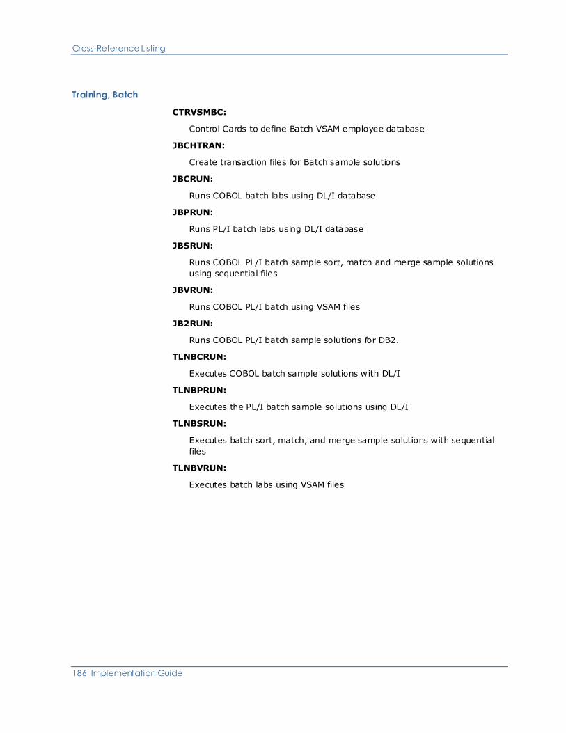
Cross-Reference Listing
186 Implementation Guide
Training, Batch
CTRVSMBC:
Control Cards to define Batch VSAM employee database
JBCHTRAN:
Create transaction files for Batch sample solutions
JBCRUN:
Runs COBOL batch labs using DL/I database
JBPRUN:
Runs PL/I batch labs using DL/I database
JBSRUN:
Runs COBOL PL/I batch sample sort, match and merge sample solutions
using sequential files
JBVRUN:
Runs COBOL PL/I batch using VSAM files
JB2RUN:
Runs COBOL PL/I batch sample solutions for DB2.
TLNBCRUN:
Executes COBOL batch sample solutions with DL/I
TLNBPRUN:
Executes the PL/I batch sample solutions using DL/I
TLNBSRUN:
Executes batch sort, match, and merge sample solutions with sequential
files
TLNBVRUN:
Executes batch labs using VSAM files

Installation Members
Appendix B: Install Members 187
VSAM Data Sets
CREORGHD:
Control Cards to reorganize and reload HELP database
CREORGWK, CREPRODD, CREPROLD, CREPUNLD:
Control Cards to clear and reinitialize the WORK files
CTDFCCL:
Control Cards to delete/define all TDF VSAM data sets
CTDFHELP:
Control Cards to delete/define the TDF HELP database
CTDFTDD:
Control Cards to delete/define the CA Telon TDF file
CTDFTDF, CTDFVSAM:
Control Cards to delete/define the CA Telon TDF file
JVERFY:
Verifies the integrity of TDF VSAM data sets
TLNVERFY:
Verifies the integrity of TDF VSAM data sets
Installation Members
The alphabetical listing of the members contains full information on each. If the
additional information about the member is available elsewhere in the CA Telon
documentation, the Notes item contains a reference.

Installation Members
188 Implementation Guide
Format of Entries
Each member in this list appears in the following format:
MEMBER NAME
This statement describes the purpose and function of the member. This
statement if followed by more specific items:
Uses—A list of the members this member uses during its execution
Used by—A list of the members that use this member during their execution
Parameters—A list of the most common parameters set within this member.
This often is not an exhaustive listing of parameters.
Notes—An expanded description of the module or a reference to further
information elsewhere.
N/A after an information item indicates that the item does not apply to that
particular member.
If you encounter any unexpected results in running these jobs, contact Customer
Support according to the procedures established at your installation.
#CLISTS
This job creates a variable blocked CLIST data set with LRECL=255 and copies all
CLIST members from the INSTALL data set into CLIST.
Uses—TLNCLIST
Used by—N/A
Parameters:
■ OLDLIB—INSTALL data set with fixed block CLISTS
■ NEWLIB—CLIST data set to be created
Notes—Only used when you require a variable blocked CLIST data set.
#CUSTBKP
This job stream customizes the GDG backup procedures. If you have standard
VSAM backup procedures already in place, you do not have to use these
procedures.
Uses—N/A

Installation Members
Appendix B: Install Members 189
Used by—N/A
Parameters—NONE
For more information, see Managing the Environment.
#CUSTCTL
These control cards are used as SYSIN to #CUSTJCL job stream. You must edit
these to customize all members of the INSTALL data set to your installation's
profile.
Uses—N/A
Used by—#CUSTJCL
Parameters—NONE
Notes—These control cards must be modified for each installation.
#CUSTJCL
This job makes global changes to the INSTALL data set. Prior to executing this,
make sure that you have modified both this member and the #CUSTCTL member
and that neither contain any @ symbols.
Uses—Requires #CUSTCTL as SYSIN data set which specifies the changes to all
the other members in the data set with the lowest level qualifier INSTALL.
Used by—N/A
Parameters—NONE
Notes—This must be modified.
#$HELP
This Help member provides further information about the CA Telon generate,
compile, and link PROC generation options.
Uses—N/A
Used by—N/A
Parameters—N/A
@TDF
CLIST model used to execute the CA Telon Design Facility (TDF).
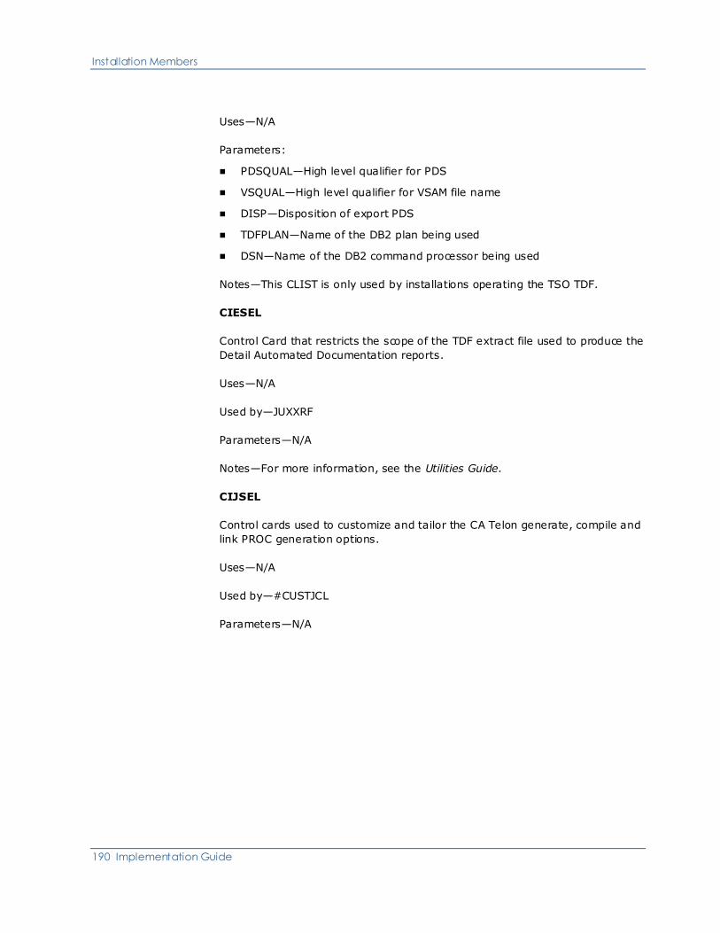
Installation Members
190 Implementation Guide
Uses—N/A
Parameters:
■ PDSQUAL—High level qualifier for PDS
■ VSQUAL—High level qualifier for VSAM file name
■ DISP—Disposition of export PDS
■ TDFPLAN—Name of the DB2 plan being used
■ DSN—Name of the DB2 command processor being used
Notes—This CLIST is only used by installations operating the TSO TDF.
CIESEL
Control Card that restricts the scope of the TDF extract file used to produce the
Detail Automated Documentation reports.
Uses—N/A
Used by—JUXXRF
Parameters—N/A
Notes—For more information, see the Utilities Guide.
CIJSEL
Control cards used to customize and tailor the CA Telon generate, compile and
link PROC generation options.
Uses—N/A
Used by—#CUSTJCL
Parameters—N/A

Installation Members
Appendix B: Install Members 191
CINPTPCH
IEBPTPCH control card that imports a partitioned data set (PDS) member into
the TDF.
Uses—N/A
Used by—TLNUMDEF
Parameters—N/A
Notes—This control card contains a PUNCH statement with two operands:
TYPORG=PO,MAXNAME=1. This statement converts the PDS member that is
being imported into sequential form so that the actual import step can store the
information on the appropriate TDF VSAM files.
CIPSEL
Control card that restricts the scope of the TDF extract file used to produce the
Detail Automated Documentation reports.
Uses—N/A
Used by— JUXXRF, TLNUXXRF
Parameters—N/A
Notes—For more information, see the Utilities Guide.
CIRSEL
Control Card that specifies the Summary Automated Documentation reports that
you want.
Uses—N/A
Used by—JUXREF, TLNUXREF
Parameters—N/A
Notes—For more information, see the Utilities Guide.

Installation Members
192 Implementation Guide
CIXSEL
Control Card that restricts the scope of the Summary Automated Documentation
reports.
Uses—N/A
Used by—JUXTRT, TLNUXTRT
Parameters—N/A
Notes—For more information, see the Utilities Guide.
CIXSRT
Control Card that specifies the sort sequence for the Automated Documentation
Global Cross-Reference Data file.
Uses—N/A
Used by—JUXXRF, TLNUXXRF
Parameters—N/A
Notes—This is the sort sequence required for the Detail Automated
Documentation reports. For more information, see the Utilities Guide.
CREORGHD, CREORGWK, CREPRODD, CREPROLD, and CREPUNLD
Control Cards used during the reorganization and reloading of the TDF VSAM
data sets.
Uses—N/A
Used by—JREORGPR, JREORGWK, JREORGHD
Parameters—N/A
Notes—The procedures that use these members are documented in TDF VSAM
Data Set Maintenance in the chapter "Managing the CA Telon Environment."
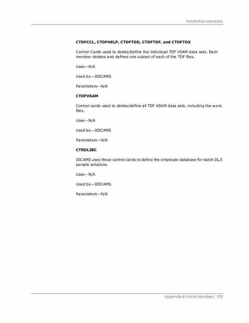
Installation Members
Appendix B: Install Members 193
CTDFCCL, CTDFHELP, CTDFTDD, CTDFTDF, and CTDFTDX
Control Cards used to delete/define the individual TDF VSAM data sets. Each
member deletes and defines one subset of each of the TDF files.
Uses—N/A
Used by—JIDCAMS
Parameters—N/A
CTDFVSAM
Control cards used to delete/define all TDF VSAM data sets, including the work
files.
Uses—N/A
Used by—JIDCAMS
Parameters—N/A
CTRDLIBC
IDCAMS uses these control cards to define the employee database for batch DL/I
sample solutions.
Uses—N/A
Used by—JIDCAMS
Parameters—N/A

Installation Members
194 Implementation Guide
CTRDLICI
IDCAMS uses these control cards to define the employee database for CICS/DL/I
sample solutions.
Uses—N/A
Used by—JIDCAMS
Parameters—N/A
CTRDLIIM
IDCAMS uses these control cards to define the employee database for
IMS/DC/DL/I sample solutions.
Uses—N/A
Used by—JIDCAMS
Parameters—N/A
CTRVSMBC
IDCAMS uses these control cards to define the employee files for BATCH/VSAM
sample solutions.
Uses—N/A
Used by—JIDCAMS
Parameters—N/A
CTRVSMCI
IDCAMS uses these Control Cards to define the training system's employee files
for CICS/VSAM training classes.
Uses—N/A
Used by—JIDCAMS
Parameters—N/A

Installation Members
Appendix B: Install Members 195
J*****L CA Telon Generate, Compile and Link JOB
After completing your installation, you will notice a number of jobs that were
created by the installation process.
Each JOB is a variation of the CA Telon generate, compile, and link model
described next. Each JOB is named according to the convention described next
and generated to contain the appropriate parameters for the specific
environment, language, teleprocessor, DBMS pre-compiler, and generator
options requested by CIJSEL or CSELECT.
Format
J12345L
■ J—CA Telon job literal
■ 1—DBMS pre-compiler (N,2,S,M) where N=none, 2=DB2 pre-compiler,
S=IDMS SQL pre-compiler, M=Datacom pre-compiler
■ 2—Target environment (B,C,I,S) where B=Batch, C=CICS, I=IMS, S=CICS
Client
■ 3—Location of CA Telon source (P,V,X) where P=PDS, V=CA PANVALET,
X=TDF
■ 4—Generate (G,O) where G=generate host source
■ 5—Host Language (C,P,2) where C=LE/COBOL, P=PL/I, 2=COBOL II and
above
■ L—Link (L) where L=do link-edit

Installation Members
196 Implementation Guide
Example
J2IXGCL
■ J—CA Telon job literal
■ 2—DB2 pre-compiler
■ I—IMS target environment
■ X—CA Telon source on TDF
■ G—Generate host source
■ C—COBOL
■ L—Link
Uses—TL*****L
Used by—N/A
Parameters—Parameters vary according to each variation. See component
member $010 in the INSTALL data set for all available parameters and #$HELP
for more information about which parameters apply to a specific variation.
Notes—The parameters are only set in either the PROCedure or its associated
JOB, not in both.
Within each of these PROCs, there are certain PARMs that can be used with the
ADPACTLC program that start with @:
Parameter Substituted value
@JULDATE Current Julian Date—Format YYDDD
@G1DATE Current Gregorian Date—Format
MMDDYY
@G2DATE Current Gregorian Date—Format
MM/DD/YY
@JOBNAME Name of Job invoking ADPACTLC
@JOBNUM Job number (assigned by JES2) of Job
invoking ADPACTLC
When you use an @ in the Input card that is not part of a Parm, you must code
it as @@. If you fail to do this, you get a return code of 16 and the error message
ADPACTLC SYNTAX ERROR IN PARM FIELD.

Installation Members
Appendix B: Install Members 197
Other JCL
The next few pages list other sets of JCL delivered CA Telon.
JASMPTBL
Job that assembles the printer carriage control table used by CICS nonterminal
application programs that write reports directly to a printer.
Uses—N/A
Used by—N/A
Parameters—N/A
Notes—See the Installation guide for details.
JBCHTRAN
Job that creates the four transaction files for the Batch training classes.
Uses—N/A
Used by—N/A
Parameters—N/A
Notes—This is required for all CA Telon Batch training classes.
JBCRUN
Job that runs the COBOL Batch sample solutions using the DL/I employee
databases.
Uses—TLNBCRUN
Used by—N/A
Parameters:
■ TEAM—Team number (1 to 5)
■ LAB—Lab number (1 to 4)
■ PGMID—Program ID (for example, XX10, XX20)
■ PSB—PSB name (for example, TRPSBCB)
Notes—Required for COBOL Batch sample solutions using DL/I databases.

Installation Members
198 Implementation Guide
JBPRUN
Job that runs the Batch PL/I class labs against the DL/I employee databases.
Uses—TLNBPRUN
Used by—N/A
Parameters:
■ TEAM—Team Number (1 to 5)
■ LAB—Batch Lab Assignment (1 to 4)
■ PGMID—The Program ID to be Tested.
■ PSB—PSB Name (i.e., TRPSBPB)
Notes—Required for PL/I Batch classes using DL/I databases.
JBSRUN
Job that runs the Batch training class labs using sequential files.
Uses—TLNBSRUN
Used by—N/A
Parameters:
■ TEAM—Team Number (1 to 5)
■ LAB—Batch Lab Assignment (1 to 4)
■ LOADMD1—Load Module Name to be tested for Lab 1
■ LOADMD2—Load Module Name to be tested for Lab 2
■ LOADMD3—Load Module Name to be tested for Lab 3
■ USRLOAD—User Training Load Library
■ TLNLOAD—CA Telon Load Library
Notes—Required for the Batch training classes.
JBVRUN
Job that runs the Batch class sample solutions using the employee VSAM files.
Uses—TLNBVRUN
Used by—N/A

Installation Members
Appendix B: Install Members 199
Parameters:
■ TEAM—Team Number (1 to 5)
■ LAB—Lab Number (1 to 4)
■ PGMID—Program ID (for example, XX10, XX20)
■ LANG—Language (1 = COBOL, 2 = PL/I)
■ TLNLOAD—CA Telon Load Library
Notes—Required for the CA Telon Batch sample solutions using VSAM files.
JB2RUN
Job that runs the Batch class programs for DB2.
Uses—N/A
Used by—N/A
Parameters:
■ PROGRAM—Load module of program being tested.
■ PLAN—DB2 Plan Name
■ LIB—Application Load Library
Make sure all DELETE and EXTRACT DDnames contain the appropriate team
file names.
Notes—Required for the Batch sample solutions.
JCPBMS
Job that assembles a BMS map from generated BMS source.
Uses—TLNCPBMS
Used by—N/A
Parameters:
■ SRCLIB—PDS containing BMS source
■ SRCMEM—BMS source member within SRCLIB
■ BMSPARM—Type of BMS output (Default = MAP)
Notes—Required for all CICS installations using BMS mapping.

Installation Members
200 Implementation Guide
JIDCAMS
Job that is used as a model job stream for executing IBM's IDCAMS.
Uses—CTDFVSAM, CTDFHELP, CTDFCCL, CTDFTDD, CTDFTDF, or CTDFTDX.
Used by—N/A
Parameters—N/A
Notes—The INSTALL data set member JIDCAMS is initially set up to handle the
loading of the TDF VSAM files. You can use it for any IDCAMS utility by changing
the SYSIN reference at the end of the job stream.
JIPMFS
Job that assembles an MFS map from generated MFS source.
Uses—TLNIPMFS
Used by—N/A
Parameters:
■ SRCLIB—PDS containing MFS source
■ SRCMEM—MFS source member within SRCLIB
Notes—Required for all IMS installations using MFS for mapping.
■ LOAD—Library to load the executable modules.
■ Member—Member of the LINKCRDS PDS that contains the link CNTL cards
for this Load Library.
Notes—Required for all installations before any CA Telon system processing, and
must be run for the LOAD library.
JREORGHD
Job that is used to delete/define and reinitialize the CA Telon HOLD file.
Uses—CREORGWK, CREPRODD, CREPROLD, CREPUNLD
Used by—N/A
Parameters—none

Installation Members
Appendix B: Install Members 201
JREORGPR
Job that is used to unload the CA Telon VSAM data sets, delete and redefine
them, and reload them.
Uses—CREORGHD, CREPRODD, CREPROLD, CREPUNLD, CREORGWK
Used by—N/A
Parameters—none
JREORGWK
Job that deletes/defines and reinitializes the three CA Telon VSAM work files.
Uses—CREORGHD, CREORGWK, CREORGDD, CREORGLD, CREPUNLD
Used by—N/A
Parameters—none
JUBK1
Job that creates a model data set control block (DSCB). This is used when you
use GDGs to back up CA Telon TDFs.
Uses—N/A
Used by—N/A
Parameters—N/A
JUBK2
JCL used to GDG initialization of the backup tapes used to back up CA Telon files.
Uses—TLNUBK2
Used by—N/A
Parameters—N/A

Installation Members
202 Implementation Guide
JUBK3
Job that creates the uncatalogued backup files from the TDF VSAM data sets.
Uses—TLNUBK3
Used by—N/A
Parameters—N/A
JUBK4A
Job that provides IBM IDCAMS delete/define and repro for TDF restoration from
GDG backup files.
Uses—TLNUBK4A
Used by—N/A
Parameters—N/A
JUBK4B
Job used to do a partial restore from a backup tape to a TDF file.
Uses—TLNUBK4B
Used by—N/A
Parameters—N/A
JUCAD2
Job used to import DB2 tables in batch mode.
Uses—TLNUCAD2
Used by—N/A
Parameters:
■ FUNCTION—I (Import), O (Overlay), A(Append)
■ QUALIFIER—DB2 table qualifier
■ TABLENAME—DB2 table name
■ TLNNAME (optional)—(If omitted, TLNNAME defaults to first 8 characters of
table name.)

Installation Members
Appendix B: Install Members 203
JUCCCK
Job used to report on and optionally delete "orphan" custom code members
found in the TNTCCL database. For example, custom code members left in the
CA Telon Design Facility when the program to which they belong has been
deleted.
Uses—TLNUCCCK
Used by—N/A
Parameters:
■ DELFLAG—1=Delete "orphan" custom code members, 0=Do not delete
"orphan" custom code members
■ RPTOPT—S=Short format (list only "orphan" custom code members, L=Long
format (list all custom code members)
JUCVDT
Job used to run the century-date conversion utility.
Uses—TLNUCVDT
Used by—N/A
Parameters:
■ TPFRLIB—Transport library where source to be converted/reported on
resides
■ TPTOLIB—Transport library for output from conversion
■ TPFRSRC—Transport source member to be converted/reported on
■ TPTOSRC—Transport source member output from conversion
RUNTYPE—CONVERT or REPORT

Installation Members
204 Implementation Guide
JUDDEF
Job that deletes Screen, Report, Nonterminal, Driver, and Batch Definitions from
the TDF.
Uses—TLNUDDEF
Used by—N/A
Parameters:
■ TDFMEM—Screen, Report, Driver, Nonterminal, or Batch Definition name
within TDF
■ DEFTYPE—Type of TDF Definition to be deleted—PI, PD, SD, RD, DR, BD, or
ND
JUHLOAD
Job used to load new help messages or update existing help messages.
Uses—PXXDLSGO
Used by—N/A
Parameters—N/A
For more information, see Maintain TDF Help Screens in the chapter "Manage the
CA Telon Environment."
JULSTCAT
Job that executes the IBM IDCAMS LISTCAL utility against the four permanent
CA Telon TDF files.
Uses—N/A
Used by—N/A
Parameters—N/A

Installation Members
Appendix B: Install Members 205
JUMDBD
Job that imports DBD information from existing DBD source code into the TDF.
Depending on Runtype, this job may overlay existing DBD information.
Uses—TLNUMDBD
Used by—N/A
Parameters:
■ SRCLIB—PDS containing database definition source code
■ SRCMEM—Database definition source member name in SRCLIB
For more information, see the Utilities Guide.
JUMDEF
Job that imports Screen, Nonterminal, Report, or Driver Definitions into the TDF
from CA Telon source code.
Uses—TLNUMDEF
Used by—N/A
Parameters:
■ SRCLIB—PDS containing CA Telon Screen, Report, or Driver Definition
■ SRCMEM—CA Telon Screen, Nonterminal, Report, or Driver source member
name in SRCLIB
For more information, see the Utilities Guide.
JUMDFE
Job that imports screen, nonterminal, report, driver, store procedure, and panel
defintions into the TDF from CA Endevor SCM.
Uses—TLNUMDFE
Used by—N/A
Parameters
■ SCRCMEM—CA Telon Definition member name in PANLIB
■ NDVRENV—CA Endevor SCM Environment
■ NDVRSTG—CA Endevor SCM stage for retrieval

Installation Members
206 Implementation Guide
■ NDVRSUB—CA Endevor SCM subsystem
■ NDVRSYS—CA Endevor SCM system
■ NDVRTYP—CA Endevor SCM stage for retrieval
JUMPAN
Job that imports screen, nonterminal, report or driver definitions into the TDF
from CA Panvalet.
Uses—TLNUMPAN
Used by—N/A
Parameters:
■ PANLIB—CA Panvalet library containing the CA Telon screen, nonterminal,
report, stored procedure, or driver definition
■ SRCMEM—CA Telon Definition member name in PANLIB
For more information, see the Utilities Guide.
JUMPSB
Job that imports PSB data from existing PSB source code into the TDF.
Uses—TLNUMPSB
Used by—N/A
Parameters:
■ SRCLIB—PDS containing the PSB source code
■ SRCMEM—PSB source code member name in SRCLIB
For more information, see Import/Export Procedures in the Utilities Guide.
JUPIMG
Job that creates a formatted print of a TDF Panel Image
Uses—TLNUPIMG
Used by—N/A
Parameter
■ TDFMEM—Header-ID of the TDF Panel Image to be printed
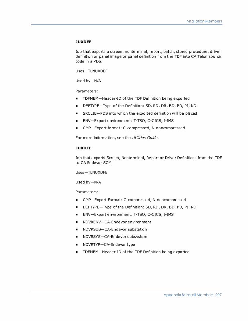
Installation Members
Appendix B: Install Members 207
JUXDEF
Job that exports a screen, nonterminal, report, batch, stored procedure, driver
definition or panel image or panel definition from the TDF into CA Telon source
code in a PDS.
Uses—TLNUXDEF
Used by—N/A
Parameters:
■ TDFMEM—Header-ID of the TDF Definition being exported
■ DEFTYPE—Type of the Definition: SD, RD, DR, BD, PD, PI, ND
■ SRCLIB—PDS into which the exported definition will be placed
■ ENV—Export environment: T-TSO, C-CICS, I-IMS
■ CMP—Export format: C-compressed, N-noncompressed
For more information, see the Utilities Guide.
JUXDFE
Job that exports Screen, Nonterminal, Report or Driver Definitions from the TDF
to CA Endevor SCM
Uses—TLNUXDFE
Used by—N/A
Parameters:
■ CMP—Export Format: C-compressed, N-noncompressed
■ DEFTYPE—Type of the Definition: SD, RD, DR, BD, PD, PI, ND
■ ENV—Export environment: T-TSO, C-CICS, I-IMS
■ NDVRENV—CA-Endevor environment
■ NDVRSUB—CA-Endevor substation
■ NDVRSYS—CA-Endevor subsystem
■ NDVRTYP—CA-Endevor type
■ TDFMEM—Header-ID of the TDF Definition being exported

Installation Members
208 Implementation Guide
JUXPAN
Job that exports screen, nonterminal, report, stored procedure, or driver
definitions from the TDF to CA Panvalet.
Uses—TLNUXPAN
Used by—N/A
Parameters:
■ TDFMEM—Header-ID of the TDF Definition being exported
■ DEFTYPE—Type of the Definition: SD, RD, DR, BD, PD, PI, ND, SP
■ PANLIB—CA Panvalet library into which the exported definition will be placed
■ ENV—Export environment: T-TSO, C-CICS, I-IMS
■ CMP—Export format: C-compressed, N-noncompressed
For more information, see Import/Export Procedures in the Utilities Guide.
JUXPRT
Job used to print Panel Images and Program Definitions from the TDF.
Uses—TLNUXPRT
Used by—N/A
Parameters:
■ TDFMEM—Header-ID of the TDF item being exported
■ DEFTYPE—Type of above entity: SD, RD, DR, BD, PD, PI, ND, SP
JUXREF
Job that creates Summary Automated Documentation reports.
Uses—TLNUXREF, CIRSEL
Used by—N/A
Parameters:
■ SELCTL—Selection Card DSname
For more information, see the Utilities Guide.

Installation Members
Appendix B: Install Members 209
JUXTRT
Job that creates Summary Automated Documentation Extract Files.
Uses—TLNUXTRT, CIXSEL
Used by—N/A
Parameters:
■ SELCTL—Selection Card DSname
For more information, see the Utilities Guide.
JUXXRF
Job that creates Detail Automated Documentation reports.
Uses—TLNUXXRF, CIESEL, CIPSEL, CIXSRT
Used by—N/A
Parameters:
■ PDSn—Library to search for "data elements" n = 1 to 9.
■ SELCTL—Entity Selection Card DSname
■ SELPARM—CA Telon Parameter Selection Card DSNAME
■ TITLE—Optional title to add to report title
For more information, see the Utilities Guide.
JVERFY
Job used to verify the integrity of TDF VSAM data sets.
Uses—TLNVERFY
Used by—N/A
Parameters:
■ TDFFILE—DSN of TDF file being verified
■ KEYLEN—Length of the key for the file being verified:
– 10 for TNTDF and TNTDFW
– 13 for TNTDD and TNTDDW
– 18 for TNHELP and TNTCCL

Installation Members
210 Implementation Guide
– 32 for TNTDX and TNTDXW
Note: Add the DELETE parameter to the length of the key for the file
being verified to delete bad or missing blocks for that specific file. For
example:
KEYLEN = ##,DELETE
■ OPTION—Processing option:
– 0 if keylen=10
– 2 is keylen=32
– 3 if keylen=13
– 8 if keylen=18
For more information, see Verify TDF VSAM Data Sets in the chapter, "Manage
the CA Telon Environment."
JZAPLOGO
Job used in the installation to customize your company's logo on the first screen
of the TDF. For more information, see the Installation Guide.
Uses—N/A
Used by—N/A
Parameters—N/A
TL*****L CA Telon Generate, Compile, and Link PROCedure
After completing your installation, you will notice a number of PROCs that were
created by the installation process.
Each PROC is a variation of the CA Telon generate, compile, and link Paradigm
described next. Each PROC is named according to the convention described next
and generated to contain the appropriate parameters for the specific
environment, language, teleprocessor, DBMS pre-compiler, and generator
options requested by CIJSEL.

Installation Members
Appendix B: Install Members 211
Format
TL12345L
■ TL—CA Telon PROC Literal
■ 1—DBMS Pre-Compiler (N,2) where N=none, 2=DB2 pre-compiler
■ 2—Target Environment (B,C,I) where B=Batch, C=CICS, I=IMS
■ 3—Location of CA Telon Source (P,V,X) where P=PDS, V=CA-PANVALET,
X=TDF
■ 4—Generate (G,O) where G=generate host source
■ 5—Host Language (C,P,2) where C=LE/COBOL, P=PL/I, 2=COBOL II
■ L— Link (L) where L=do link-edit
Example
TLNIXGCL
■ TL—CA Telon PROC Literal
■ N—No DBMS Pre-Compiler
■ I—IMS Target Environment
■ X—CA Telon Source on TDF
■ G—Generate Host Source
■ C—COBOL for OS/390
■ L—Link
Uses—N/A
Used by—J*****L
Parameters—Parameters vary according to each variation. For more information
about which parameters apply to a specific variation, see component member
$010 in the INSTALL data set for all available parameters and #$HELP.
Notes—The parameters are only set in either the PROCedure or its associated
JOB, not in both.

Installation Members
212 Implementation Guide
Other JCL
The next few pages list other sets of JCL delivered with the CA Telon product.
TLNBCRUN
Procedure that executes the COBOL Batch sample solutions using DL/I
databases.
Uses—N/A
Used by—JBCRUN
Parameters:
■ TEAM—Team Number (1 to 5)
■ LAB—Lab Number (1 to 4)
■ PGMID—Program ID (for example, XX10)
■ PSB—PSB Name (for example, TRPSBCB)
■ USRLOAD—pdsqual.LOADTRGC
Notes—The above parameters are set in either this member or its associated job,
not in both.
TLNBPRUN
Procedure that executes the PL/I Batch sample solutions using DL/I databases.
Uses—N/A
Used by—JBPRUN
Parameters:
■ TEAM—Team Number (1 to 5)
■ LAB—Lab Number (1 to 4)
■ PGMID—Program ID (i.e., XX20)
■ PSB—PSB Name (i.e., TRPSBPB)

Installation Members
Appendix B: Install Members 213
■ USRLOAD—User Training Load Library (LOADTRGC)
Notes—The above parameters are only set in either this member or its
associated job, not in both.
TLNBSRUN
Procedure that runs the Batch sample solutions using sequential files.
Uses—N/A
Used by—JBSRUN
Parameters:
■ TEAM—Team Number (1 to 5)
■ LAB—Batch Lab Assignment (1 to 4)
■ LOADMD1—Load module Name to be tested for Lab 1
■ LOADMD2—Load module Name to be tested for Lab 2
■ LOADMD3—Load module Name to be tested for Lab 3
■ USRLOAD—User Training Load Library
■ TLNLOAD—CA Telon Load Library
Notes—Required for the Batch training classes.
TLNBVRUN
Procedure that runs the Batch VSAM sample solutions.
Uses—N/A
Used by—JBVRUN
Parameters:
■ TEAM—Team Number (1 to 5)
■ LAB—Lab Number (1 to 4)
■ PGMID—Program ID (i.e., XX10)
■ USRLOAD—User Training Load (LOADTRGC)
■ TLNLOAD—CA Telon Load Library
Notes—The above parameters are only set in either this member or its
associated job, not in both.
TLNCLIST

Installation Members
214 Implementation Guide
Procedure that creates a variable blocked CLIST data set with LRECL = 255 and
copies all CLIST members from the INSTALL data set.
Uses—N/A
Used by—#CLISTS
Parameters—OLDLIB=dsn (where dsn = the data set name of the INSTALL data
set with fixed block CLISTS), NEWLIB = dsn (where dsn = the data set name of
the CLIST data set to be created).
TLNCPBMS (CICS only)
Procedure that assembles a BMS map from generated BMS source code.
Uses—N/A
Used by—JCPBMS
Parameters:
■ SRCLIB—PDS containing BMS source
■ SRCMEM—BMS source member within SRCLIB
■ BMSPARM—type of BMS output to generate (Default = MAP)
Notes—Required for all CICS installations using BMS mapping. The above
parameters do not have to be included in both this procedure and the job running
it.
TLNIPMFS
Procedure that assembles an MFS map from generated MFS source code.
Uses—N/A
Used by—JIPMFS
Parameters:
■ SRCLIB—PDS containing MFS source
■ SRCMEM—MFS source member within SRCLIB
■ IMSRES—IMS ResLib
■ MFSREF—IMS Referral Lib

Installation Members
Appendix B: Install Members 215
■ MFSFRMT—IMS Format Lib
Notes—The above parameters do not have to be included in both this procedure
and the job running it.
TLNUBK2
Used to initialize GDG data sets to back up CA Telon data sets.
Uses—N/A
Used by—JUBK2
Parameters—N/A
TLNUBK3
Used to create the GDG backup tapes.
Uses—N/A
Used by—JUBK3
Parameters—N/A
TLNUBK4B
Used to do a partial restore of a TDF file from a TDF backup file.
Uses—N/A
Used by—JUBK4B
Parameters—N/A
TLNUCAD2
Used to import DB2 tables into the TDF.
Uses—N/A
Used by—JUCAD2
Parameters—N/A

Installation Members
216 Implementation Guide
TLNUCCCK
Job used to report on and optionally delete orphan custom code members found
in the TNTCCL database. For example, custom code members left in the CA Telon
Design Facility when the program to which they belong has been deleted.
Uses—N/A
Used by—JUCCCK
Parameters—N/A
■ DELFLAG—1=Delete orphan custom code members, 0=Do not delete
"orphan" custom code members
■ RPTOPT—S=Short format (list only "orphan" custom code members, L=Long
format (list all custom code members)
TLNUCVDT
Job used to run the Century-Date conversion utility.
Uses—TLNUCVDT
Used by—N/A
Parameters:
■ TPFRSRC—Transport source file to be converted/reported on
■ TPTOSRC—Transport source file output from conversion
■ RUNTYPE—"CONVERT" or "REPORT"
■ USREDITS—File containing user field edits to be converted (from and to)

Installation Members
Appendix B: Install Members 217
TLNUDDEF
Procedure that deletes screen, nonterminal, report, driver, stored procedure,
and batch definitions from the TDF.
Uses—N/A
Used by—JUDDEF
Parameters:
■ TDFMEM—Screen, Report, Driver, Nonterminal, or Batch Definition name
within TDF
■ DEFTYPE—Type of TDF Definition to be deleted—PI, PD, SD, RD, DR, BD, SP,
or ND
Notes—The above parameters do not have to be included in both this procedure
and the job running it.
TLNUMDBD
Procedure that imports DBD information from existing DBD source code into the
TDF.
Uses—N/A
Used by—JUMDBD
Parameters:
■ MAXSEVR—Two-digit indicator of the highest acceptable Comparison
severity
■ RUNTYPE—Indicator defining the scope of import processing
■ SRCLIB—PDS containing database definition source code
■ SRCMEM—Database definition source member name in SRCLIB
Notes—The above parameters do not have to be included in both this procedure
and the job running it. For more information, see the Utilities Guide.
TLNUMDEF
Procedure that imports screen, nonterminal, report, stored procedure, and
driver definitions into the TDF from CA Telon source code.
Uses—CINPTPCH
Used by—JUMDEF

Installation Members
218 Implementation Guide
Parameters:
■ MAXSEVR—Two-digit indicator of the highest acceptable comparison
severity
■ RUNTYPE—Indicator defining the scope of import processing
■ SRCLIB—PDS containing CA Telon Screen, Report, Nonterminal, or Driver
Definition
■ SRCMEM—CA Telon Screen, Nonterminal, Report, or Driver source member
name in SRCLIB
For more information, see the Utilities Guide.
TLNUMDFE
Procedure that imports screen, nonterminal, report, driver, batch, stored
procedure, and panel definitions into the TDF from All Fusion Endevor Change
Manager
Uses—N/A
Used by—JUMDFE
Parameters
■ MAXSEVR—Two-digit indicator of the highest acceptable comparison
severity
■ NDVRENV—CA Endevor SCM environment
■ NDVRSTG—CA Endevor SCM stage for retrieval
■ NDVRSYS—CA Endevor SCM system
■ NDVRSUB—CA Endevor SCM subsystem
■ NDVRTYP—CA Endevor SCM type
■ NDVRCID—CA Endevor SCM CCID paramater (optional)
■ NDVRCMT—CA Endevor SCM comment parameter (optional)
■ RUNTYPE—Indicator defining the scope of import processing
■ SRCMEM—CA Telon Definition member name in CA Endevor SCM
TLNUMPAN
Procedure that imports Screen, Nonterminal, Report, and Driver Definitions into
the TDF from CA Panvalet.
Uses—N/A
Used by—JUMPAN

Installation Members
Appendix B: Install Members 219
Parameters:
■ MAXSEVR—Two-digit indicator of the highest acceptable Comparison
severity
■ RUNTYPE—Indicator defining the scope of import processing
■ PANLIB—CA Panvalet library containing CA Telon Screen, Nonterminal,
Report, or Driver Definition
■ SRCMEM—CA Telon Definition member name in PANLIB
Notes—See the Utilities for details.
TLNUMPSB
Procedure that imports PSB data from existing PSB source code into the TDF.
Uses—N/A
Used by—JUMPSB
Parameters:
■ SRCLIB—PDS containing the PSB source code
■ SRCMEM—PSB source code member name in SRCLIB
Notes—The above parameters do not have to be included in both this procedure
and the job running it. For more information, see the Utilities Guide.
TLNUPIMG
Proceudre that creates a formatted print of a TDF Panel Image.
Uses—N/A
Used by—JUPIMG
Parameters:
■ TDFMEM—Header-ID of the TDF Panel Image to be printed.
Notes—See the "Important Parameters" appendix in this guide for more
information.
Installation Members
220 Implementation Guide
TLNUVDFI
Creates a PC import file from a mainframe CA Panvalet file.
Uses—N/A
Used by—JUVDFF
Parameters—
■ PCTLIB = PC transfer library
■ PANLIB = user source library
■ SRCMEM = name of member with CA Telon source
TLNUXDEF
Procedure that exports Panel Images, Panel Definitions, and Program Definitions
from the TDF to CA Telon source code in a PDS.
Uses—N/A
Used by—JUXDEF
Parameters:
■ TDFMEM—Header-ID of the TDF Definition being exported
■ DEFTYPE—Type of the Definition: SD, RD, DR, BD, PD, PI, ND, SP
■ SRCLIB—PDS into which the exported definition will be placed
■ ENV—Export environment: T-TSO, C-CICS, I-IMS
■ CMP—Export format: C-compressed, N-noncompressed
Notes—The above parameters do not have to be included in both this procedure
and the job running it. For more information, see the Utilities Guide.

Installation Members
Appendix B: Install Members 221
TLNUXDFE
Procedure that exports Screen, Report, Driver, Batch and Panel Definitions from
the TDF to CA Endevor SCM.
Uses—N/A
Used by—JUXDFE
Parameters:
■ DEFTYPE—Type of the Definition: SD, RD, DR, BD, PD, PI, ND, or SP
■ CMP—Export format: C-compressed, N-noncompressed
■ ENV—Export environment: T-TSO, C-CICS, I-IMS
■ NDVRENV—All Fusion Endevor Change Manager environment
■ NDVRSUB—All Fusion Endevor Change Manager subsystem
■ NDVRSYS—All Fusion Endevor Change Manager system
■ NDVRTMP—All Fusion Endevor Change Manager type
■ NDVRUP—All Fusion Endevor Change Manager update if present flag
(optional)
■ NDVRDVR All Fusion Endevor Change Manager override signout flag
(optional)
■ NDVRCID All Fusion Endevor Change Manager CCID parameter (optional)
■ NDVRPRG All Fusion Endevor Change Manager processor group parameter
(optional)
■ NDVRCMT All Fusion Endevor Change Manager comment parameter
(optional)
■ TDFMEM—Header-ID of the TDF Definition being exported
TLNUXPAN
Procedure that exports Screen, Report, and Driver Definitions from the TDF to CA
Panvalet.
Uses—N/A
Used by—JUXPAN
Parameters:
■ TDFMEM—Header-ID of the TDF Definition being exported
■ DEFTYPE—Type of the Definition: SD, RD, DR, BD, PD, PI, ND, or SP
Installation Members
222 Implementation Guide
■ PANLIB—CA Panvalet library into which the exported definition will be placed
■ ENV—Export environment: T-TSO, C-CICS, I-IMS
■ CMP—Export format: C-compressed, N-noncompressed
Notes—The above parameters do not have to be included in both this procedure
and the job running it. For more information, see the Utilities Guide.
TLNUXPRT
Procedure that prints TDF Panel Images and Program Definitions.
Uses—N/A
Used by—JUXPRT
Parameters:
■ TDFMEM—Header-ID of the TDF item being exported
■ DEFTYPE—Type of above entity; SD, RD, DR, BD, PD, PI, ND, or SP
TLNUXREF
Procedure that creates Summary Automated Documentation reports.
Uses—N/A
Used by—JUXREF
Parameters:
■ SCRUNIT—Name of Scratch UNIT (e.g., SYSDA)
■ SELCTL—Selection Card DSname
■ TLNLIB—Library in which CA Telon modules reside
■ VSDISP—DISP of VSAM files
■ VSQUAL—High level qualifier for CA Telon TDF VSAM files
■ XCUST—Customer Code Extract DSname
■ XDBSEG—Segment Extract DSname
■ XENT—Entity Extract DSname
Notes—The above parameters are only set in this member or its associated job,
not in both.
TLNUXTRT
Procedure that creates Summary Automated Documentation Extract Files.

Installation Members
Appendix B: Install Members 223
Uses—CIXSEL
Used by—JUXTRT
Parameters:
■ PDSUNIT—UNIT for DISK
■ PDSVOL—VOL SER for DISK
■ SCRUNIT—Name of Scratch UNIT (e.g., SYSDA)
■ SELCTL—Selection Card DSname
■ TLNLIB—Library in which CA Telon modules reside
■ VSDISP—DISP of VSAM files
■ VSQUAL—High level qualifier for CA Telon TDF VSAM files
■ XCUST—Customer Code Extract DSname
■ XDBSEG—Segment Extract DSname
■ XENT—Entity Extract DSname
Notes—The above parameters are only set in this member or its associated job,
not in both.
TLNUXXRF
Procedure that creates Detail Automated Documentation reports.
Uses—CIXSRT
Used by—JUXXRF
Parameters:
■ FUNC—CA Telon PDS Utility function: XREFCBL, XREFEDIT, XREFPLI
■ PDS1...—Library to search for "data elements"
■ PDSn n = 1 to 9.
■ PDSMBR—Scope of search indicator (Default = ALL)
■ SCRUNIT—Name of Scratch UNIT (e.g., SYSDA)
■ SELCTL—Entity Selection Card DSNAME
■ SELPARM—CA Telon Parameter Selection Card DSNAME
■ SORTCTL—SORT Control Card DSNAME
■ SORTLIB—User SortLib
■ SRCHCTL—Search Argument Control Card DSNAME

Installation Members
224 Implementation Guide
■ TITLE—Optional title to add to report title
■ TLNLIB—Library in which CA Telon modules reside
■ TRACE—Y or N
■ VSQUAL—High level qualifier for CA Telon TDF VSAM files
■ XREFOUT—Detail Entity Extract PDS DSNAME
Notes—The above parameters are only set in this member or its associated job,
not in both.
TLNVERFY
Procedure used to verify the integrity of the TDF VSAM data sets.
Uses—N/A
Used by—JVERFY
Parameters:
■ TDFFILE—DSN of TDF file being verified
■ KEYLEN—Length of the key for the file being verified:
– 10 for TNTDF and TNTDFW
– 13 for TNTDD and TNTDDW and TNTCCL
– 18 for TNHELP
– 32 for TNTDX and TNTDXW
Note—Add the DELETE parameter to the length of the key for the file being
verified to delete bad or missing blocks for that specific file. For example,
KEYLEN = ##,DELETE
■ OPTION—Processing option:
– 0 if keylen=10
– 2 if keylen=32
– 3 if keylen=13
– 8 if keylen=18
Note: See Verifying TDF VSAM Data Sets in the "Managing the Environment"
chapter of this guide for more information.

Appendix C: Installation Defaults for Mainframe Targets 225
Appendix C: Installation Defaults for
Mainframe Targets
The default installation settings for CA Telon mainframe targets as delivered are
described in this appendix. Certain modifications that you can make to the
various defaults are also discussed.
■ CICS installation-specific information
■ IMS installation-specific information
This section contains the following topics:
CICS Installation-Specific Information (see page 226)
IMS Installation-Specific Information (see page 232)

CICS Installation-Specific Information
226 Implementation Guide
CICS Installation-Specific Information
There are several installation options that you can customize to meet your
needs, to provide flexibility, and to meet your installation's standards. These
options affect default values for CA Telon non-procedural statements and
naming conventions.
This appendix describes the default conventions for each of the categories listed
next, and leaves room for you to insert your customized defaults, where
appropriate.
Note: If you are using PWS, see the PWS User Guide for the directories which
are the equivalent of library names.
■ Non-procedural statement defaults—Conventions for defining default values
for the CA Telon non-procedural statements
■ Library names—Conventions for naming the CA Telon libraries
■ Screen-related names—Conventions for assigning names that are based on
the screen header ID, screen ID, and application ID
■ Copy/include member names—Conventions for naming the copy/include
members that are standard for each application
■ Program names—Conventions for assigning names to generated programs
■ CICS control names—Conventions for defining CICS control information:
PSB names, transaction IDs, and BMS map names
■ General implementation considerations—Suggestions for implementing your
own conventions to supplement those specific to CA Telon
Following the discussion of conventions, there are notes of some general
approaches to conventions that are recommended for use with CA Telon
applications.
Non-Procedural Statement Defaults
The next table contains the non-procedural CA Telon statements and their
defaults. Use the space at the right to insert your installation defaults.
Statement Parameter Supplied default Installation
standard
CICSPGM BMS + N
BMSMAP + hhZnnnn **
TRACE + Y
TRANCDE + nnnn (ID)

CICS Installation-Specific Information
Appendix C: Installation Defaults for Mainframe Targets 227
Statement Parameter Supplied default Installation
standard
BMS alignment
+++
Unaligned **
GENPCBS Y
IOASTG Static
SPASTG Static
TPBSTG Static
LINEOPT Y
SCREEN ALARM + N
APPLID +++ None *
HEADER +++ hh *
ID +++ nnnn *
LANG + COB (COBOL)
OUTIFIL + SPACE
REFRESH + Y
SEGLOOP Paging forward
++
PF key 1 or 13
Paging backward PF key 2 or 14

CICS Installation-Specific Information
228 Implementation Guide
* See Screen-Related Names for further explanation
** See CICS Control Names for further explanation
+ Can be changed by the programmer in a CA Telon non-procedural statement
++ Can be overridden by procedural code
+++ Cannot be overridden by the programmer
Library names
Two libraries are used in the generation phase of CA Telon processing:
■ Screen-generation library, where the skeletal non-procedural statements
are written.
■ Screen-definition library, where you should move the skeletal statements
before completing them; often, a CA Panvalet or CA Librarian file.
Library Generated name Installation standard
Screen-generation PDS CUSTOMER.TELON.GENP
DS
Screen-definition PDS CUSTOMER.TELON
SOURCEC (for COBOL)
SOURCEP (for PL/I)

CICS Installation-Specific Information
Appendix C: Installation Defaults for Mainframe Targets 229
Screen-related names
Screen images, as defined using the Screen Design Aid component of CA Telon,
are always identified by a two-character header ID (hh) and a four-character
screen ID (nnnn). CA Telon uses these IDs to generate various names related to
the screen, including program and control blocks.
You can add another level of screen identifier; a variable number of characters
that define an application ID (such as, INV). To do this, use the APPLID keyword
parameter of the SCREEN statement. When an application ID is defined, the
generated names, as defined for your installation, can make use of the
application ID variable (shown as aa for our purposes) in the same way that it
uses the hh and nnnn variables noted above. As installed, however, the
application ID is not used in the generation of names.
The following variables are used:
■ hh—Header ID
■ nnnn—Screen ID
■ aa—Application ID (not used in supplied defaults but available if defined on
the SCREEN statement.)
The next table tells how the header ID, screen ID, and application ID are used to
generate names related to the screen itself.
Name Supplied default Installation default
Screen member name*
screen generation library
hhnnnn
Screen definition
memberin screen design
library
hhnnnn
SCREEN statement
Screen ID nnnn
Header ID Hh
APPLID None&semi. used to
define application ID for
use elsewhere
NEXTPGM parameter nnnn
* Cannot be modified in r1.0

CICS Installation-Specific Information
230 Implementation Guide
COPY/INCLUDE Member Names
CA Telon looks for several standard COPY members when it generates
application code. These COPY members are summarized next, along with their
naming conventions. See the Programming Concepts guide for more information
about these members.
Member description Supplied default Installation standard
Application Work Area hhWKAREA
DL/I Update Area hhUPDTA
PF Key Logic hhPFKnnn where nnn is
1-3 characters, supplied
by the PFKEYS parameter
of the SCREEN statement
Program Names
CA Telon follows the conventions displayed next when naming the CICS
program. Each assigned value refers to the name used in the COBOL
IDENTIFICATION DIVISION or the PL/I PROC OPTIONS statement (respectively,
by language).
Language and name Supplied default Installation standard
COBOL program hhCPnnn
PL/I program hhTnnnn

CICS Installation-Specific Information
Appendix C: Installation Defaults for Mainframe Targets 231
CICS Control Names
CA Telon follows the conventions displayed next when naming the control
information for use in processing a screen under CICS. For the DL/I PSB, there is
no convention as installed. You can define the names explicitly and thereby not
use the defaults in effect for your installation. To do this, use the following
parameters on the non-procedural statements.
■ CICSPGM statement PSBNAME
■ CICSPGM statement TRANCDE parameter
■ CICSPGM and CICSBMS statements BMSMAP parameter (both
specifications, if used, must be identical)
Control description Supplied default Installation standard
BMS Alignment Unaligned
BMS Map Name hhZnnnn
DL/I PSB (none supplied)
Transaction name nnnn
General Implementation Considerations
In addition to the naming conventions described previously, each installation
should establish conventions for use during the evolution of an application. For
CA Telon, these conventions might include:
■ Design conventions: Rules regarding the general and detailed design. Who
is responsible for what? What are the products that result from the design
process? Who signs off on what, and at what point?
■ Conventions for coding.
■ Conventions for testing: Rules regarding the use of BMS and which entries
are required in the CICS tables (PPT, PCT, FCT, PDIR, DDIR).
■ Conventions related to PSB/BMS generation: How is the PSB and BMS
source be used? What responsibilities do application programmers have in
the final assembly of BMS map source? Must PSB source be input to the data
dictionary?
■ Conventions related to converting an application from the test environment
to production (for example, updating the CICS tables).
IMS Installation-Specific Information
232 Implementation Guide
IMS Installation-Specific Information
CA Telon provides you with many parameters to tailor an application to the
application user, existing screens, and the IMS DB/DC environment. This has
been done to allow flexibility in meeting the various trade-offs between user
friendliness, production efficiency, and the installation's data processing
standards.
The following topics are presented in this subsection:
■ CA Telon nonprocedural statement defaults
■ Naming conventions
■ Adding new field edits
■ Preparing an application for development
■ IMS standard environment options
■ IMS conversion checklist
■ CA Telon batch JCL procedures
Installation Modifiable Parameters
Parameters used in the CA Telon nonprocedural statements that can be modified
by an installation are:
Statement Parameter Supplied default Installation
standard
SCREEN PGMCUST
LANG
REFRESH
ALARM
OUTIFIL
EOFKEY
OUTATTR
NONE
COB
Y
N
SPACE
Y
Y
SEGLOOP Paging forward
Paging backward
PF1, this default,
or PF7-PF8
PF1, this default,
or PF7-PF8
IMSPGM LINEOPT
CONVERS
LINKOPT
TRACE
1
Y
D
Y

IMS Installation-Specific Information
Appendix C: Installation Defaults for Mainframe Target s 233
Statement Parameter Supplied default Installation
standard
GENPCBS Y
IMSDRV CONVERS
GENPCBS
LINKDYN
TRACE
Y
Y
N
Y
Naming conventions are to be tailored at installation time to meet existing
standards in the following areas:
■ Screen names
■ COPY/INCLUDE member names
■ Program names
■ IMS control block names
If an installation's naming conventions for Programs or IMS control blocks cannot
be automatically generated, then manual overrides are possible on the IMSPGM,
IMSDRV, and IMSMFS statements.
Copy/Include Names
CA Telon applications make use of several standard COPY/INCLUDE members.
These members have the following naming conventions:
Member function Supplied default Installation standard
PCB List hhPROC
PCB Declaration hhPCBS
Application Work Area hhWKAREA
DLI Update Area hhUPDTA
PFKEY Code hhPFKxx (xx supplied by
SCREEN PFKEYS
parameter)

IMS Installation-Specific Information
234 Implementation Guide
COBOL Program Names
The TSO and IMS programs have the following naming conventions:
Program type Supplied default Installation standard
TSO Program hhTMnnnn
IMS Dynamic MAIN hhIMnnnn
IMS Dynamic ALIAS hhXMnnnn
IMS Driver hhIMnnnn
IMS Static Module hhSMnnnn
PLI Programs
The TSO and IMS programs have the following naming conventions:
Program type Supplied default Installation standard
TSO Program hhTnnnn
IMS Dynamic MAIN hhInnnn
IMS Dynamic ALIAS hhXnnnn
IMS Driver hhInnnn
IMS Static Module hhSnnnn
IMS Control Names
The IMS control information has the following naming conventions:
IMS function Supplied default Installation standard
TSO PSB Name NONE
IMS PSB Name(must
match the IMS Program
Name)
hhIMnnnn
Transaction Name hhIMnnnn
MFS Names Format hhnnnn
MID hhInnnn

IMS Installation-Specific Information
Appendix C: Installation Defaults for Mainframe Targets 235
IMS function Supplied default Installation standard
MOD hhOnnnn
IMS Overrides on CA Telon Statements
Use the following parameters when the above naming conventions cannot be
adhered to by an application or an installation.
Statement Parameter Installation standard
IMSPGM
TRANCDE
MFSMOD
PGMNAME
IMSDRV
TRANCDE
FRSTMOD
PGMNAME
IMSMFS
TRANCDE
SYSMSG
MFSMOD

IMS Installation-Specific Information
236 Implementation Guide
Add New Edits
This section describes how to add a new edit at your installation:
1. Decide:
■ Whether the edit is for INPUT or OUTPUT
■ What type of interface is required (ALPHA, NUMERIC, or BIT)
■ What language to use in writing the edit (it is important to use the calling
language or assembler language and in PL/I it is recommended to use
the ASM interface option)
2. Code the new edit, paying special attention to the linkage parameters.
3. Compile and link the edit subroutine. All external references should be
resolved.
Note: The name of the module in the load library must begin with an I or O
(for example, if FLDTYPE=NEWED is used for both input and output editing,
then two edit modules are required and they are named INEWED and
ONEWED).
4. Test the edit.
Note: For PWS, test the field edit using the alternative debugging tools
described in the PWS User Guide.
5. Have your CA Telon coordinator place the name of your new edit into the
EDITTBL member used by the Application Generator.

IMS Installation-Specific Information
Appendix C: Installation Defaults for Mainframe Targets 237
Prepare an Application for Development
The Programming Concepts Guide defines the tasks necessary to prepare an
application for development with CA Telon. The following is a checklist to assure
those tasks are completed. This list should be augmented to include any special
installation requirements also required.
1. Prepare DBDs for all necessary databases and create and initialize
databases.
2. Prepare a PSB accessing necessary databases (any structure, even one
including extra databases, is valid). This PSB is used for TSO testing.
3. (Optional Step) Create hhPCBS and hhPROC members to define the
structure of the PSB. This is most easily done by copying over existing
members and making global changes for new names.
4. Create hhWKAREA member by copying over an existing member and
changing any values which are different for this application. If error message
contents and flag values are standard at an installation, no changes are
necessary.
5. (Not a Required Step for DB2) Create the hhUPDTA member (if any) by
copying over an existing member and changing the length of the value to be
at least as large as the largest segment updated.
6. Create COPY or INCLUDE members for all segments to be accessed in this
application.
7. Create a Transfer Work Area copy member.

IMS Installation-Specific Information
238 Implementation Guide
CA Telon Procedures
It is recommended that installation standards be set to define CA Telon
procedures and standard modes of operation for CA Telon applications. Some
sample standards are listed next. They should be modified and expanded and
then redistributed as a part of this guide.
Starting an application
Whether applications are started using a /FORMAT command or by entering the
IMS transaction code.
TRAN code on screen
Whether the transaction code is to appear unprotected on the screen.
TRAN code specification
How transaction code values are specified, either through generated names or
by explicit specification on the IMSPGM and IMSMFS statements.
Linkage options
Under what circumstances, if any, static, dynamic, and message switch linkage
for IMS programs are used?
PSB/MFS generation
How is the PSB and MFS source used? Do application programmers have any
responsibility in the final assembly of MFS control blocks? Must PSB source be
input to the data dictionary?
Appendix D: Important Parameters 239
Appendix D: Important Parameters
Important parameters for the install are described in this appendix. The printing
and TELONTDF parameters are also included.
You will also learn how to print panel images in batch mode on the mainframe.
For more information about printing panel images from the Utilities screen, see
the Design Facility Reference Guide.
This section contains the following topics:
Print Parameters (see page 239)
Parameters Passed to TELONTDF (see page 241)
Print Parameters
The pdsqual.INSTALL(JUXPRT) job stream prints Panel Images from the batch
mode. It uses a procedure pdsqual.INSTALL(TLNUXPRT). This prints both
standard Panel Images and Batch Panel Images with Image Groups.
The job allows you to enter parameters in order to format the printed Panel
Image to your specific requirements.
Once you have set these parameters in JUXPRT, verify the job cards and submit
the job. The parameters you can set are:
LINENUM=Y&lor.N
Parameter that controls whether each panel image line should be numbered at
both ends of the line. The line numbers are separated from the Panel Image by
asterisks. Values are:
■ Y—(Default) Print line numbers
■ N—Do not print line numbers
When LINENUM=Y, JUXPRT prints in this format:
1 * TRAINING SYSTEM * 1
2 * MENU * 2
3 * * 3

Print Parameters
240 Implementation Guide
DBLSPC=Y&lor.N
Parameter that controls whether the numbered lines are printed double spaced.
The parameter is ignored when LINENUM=N. Only operational when the the first
parameter asks for line numbers. Valid values are:
■ Y—(Default) Print a blank line bounded only with asterisks between each
Panel Image line
■ N—Do not double space the Panel Image
When DBLSPC=Y and LINENUM=Y, JUXPRT prints in this format:
* *
1 * TRAINING SYSTEM * 1
* *
2 * MENU * 2
* *
3 * * 3 SHIFT=Y&lor.N
Valid only when LINENUM=N. This parameter controls whether to print column
one of your panel. Often used with batch output that can use column one for
attribute bytes and carriage control. Values are:
■ Y—Print column one characters in column 1
■ N—(Default) Discard column-1 characters, and print column-2 characters in
column 1
USECOL1=Y&lor.N
Parameter that can be used to ignore screen control characters in column one.
Values are:
■ Y—Print any characters found in column 1
■ N—(Default) Set column 1 output to spaces.
TDFMEM= hhnnnn
The header-ID combination of the Panel Image that you want to print.
Note: All the Panel Images can be printed under a given Header by specifying
the member name as the header (hh) followed by four asterisks for nnnn (for
example, TDFMEM='TR****').

Parameters Passed to TELONTDF
Appendix D: Important Parameters 241
TLNLOAD= pdsqual.LOAD
Name of the CA Telon load library.
VSQUAL= vsamqual
High-level VSAM qualifier for the TDF VSAM datasets that hold this Panel Image.
Change this only if your installation uses multiple TDF VSAM datasets.
Parameters Passed to TELONTDF
The CLIST used to call the TDF calls the mainframe CA Telon-supplied TELONTDF
program to execute the TDF. TELONTDF is also executed from procedures that
import and export members to and from the TDF.
The next table lists the mainframe CA Telon parameters that are sent to
TELONTDF when it is called (programs beginning with TN are supplied with the
CA Telon product):
Parameter Description Bytes
DLS CA Telon's Data
Language Simulator
3
Program name Application program
name to be executed by
TELONTDF (for example,
TNRADRVR)<%
8
File definition module Name of the file
definition module name,
TNFDMDL3
8
Y or N Indicates whether DFP is
installed
1
Scan time Time interval to wait, in
seconds, before
re-attempting a control
interval split in the
absence of DFP
4
Y, N, or C DLS trace option that
specifies whether to
trace DLS calls. C allows
the trace to be turned on
or off during TELONTDF
execution.
1


Appendix E: Mainframe TDF Abends 243
Appendix E: Mainframe TDF Abends
The U901 abend is an internal CA Telon abend. It is returned when a TDF
program encounters an error in attempting to perform I/O on a TDF file.
If you receive a U901 abend, run the JVERFY job (which is explained in more
detail in Appendix C) to identify (and optionally, delete) the bad or missing
blocks.
If you run JVERFY with the DELETE option, you may then need to restore selected
TDF members from your file backups. You can perform a restore by defining a
set of temporary TDF files. Next, repro your backup files into these temporary
files. Then export the members that had been deleted through the JVERFY
DELETE process, and finally, re-import the members into your permanent TDF
files.
If you encountered errors in running JVERFY after receiving a U901 abend, your
next step is to reorganize your TDF files and reinitialize your WIP files, then rerun
JVERFY. If problems are encountered at this point, contact Customer Support
according to the procedures established at your site. Be sure to have a hard
copy of your output from JVERFY (and any other jobs that you just ran against
the TDF files) when you call.
Some of the most common reasons for bad blocks occurring on TDF files are as
follows:
■ A high number of CI or CA splits (or both)
■ A file could not acquire additional extents due to lack of available space on
the pack
■ Running a CICS TDF with VSAM share options that are different from those
stated in the CA Telon installation procedures
■ Hardware errors
■ Using CA Telon files in a shared DASD environment
■ Region (for CICS), Session (for TSO) or System Failures while TDF I/O is in
progress (or all of these)
This section contains the following topics:
Recommendations for Handling U901 Abends (see page 244)

Recommendations for Handling U901 Abends
244 Implementation Guide
Recommendations for Handling U901 Abends
For large or high activity CA Telon sites, the following suggestions are offered as
possible ways to reduce or prevent U901 abends from occurring. These
recommendations are based on experiences with CA Telon clients in a variety of
environments. You must determine the need for and feasibility of implementing
any or all of these recommendations at your site.
■ Based on informal reports from CA Telon clients, the custom code file
(TNTCCL) receives the greatest number of U901 abends, probably in part
because this is often the most active and the largest of the TDF files. This file
should be reorganized nightly.
■ Reorganizing all TDF files nightly helps to improve performance and
decrease the probability of a U901 occurring. The JREORGPR job is provided
in the INSTALL data set (see TDF VSAM Data Set Maintenance in the chapter
"Manage the CA Telon Environment").
■ Reinitializing the WIP files and Hold files nightly also helps achieve the
benefits listed earlier. The JREORGHD and JREORGWK jobs are provided in
the INSTALL data set (see TDF VSAM Data Set Maintenance in the chapter
"Manage the CA Telon Environment").
■ For sites that have very large Custom Code members (for example, more
than 2000 lines) these large members should be stored in a PDS rather than
in the TDF files.
■ Sites encountering excessive CI or CA splits should increase the free space
for the files in question.
■ TDF files should be backed up regularly to help provide for recovery from
software or hardware failures.

Index 245
Index
/
/FORMAT command • 141, 153, 158, 160, 161,
164
Conversational processing • 153, 158
initiation • 141
Non-conversational Processing • 160, 161
starting a TELON conversation • 158
static link, Non-conversational processing •
164
/FORMAT Initiation • 154
for dynamic program structure • 154
for static program structure • 154
A
ABENDST parameter • 66
Above the line • 17, 18
adding new edits • 233
IMS installation specific information • 233
ALARM parameter • 229
SCREEN Statement • 229
Application Work Area • 230
COPY/INCLUDE Member Names • 230
APPLID parameter • 224, 227
SCREEN Statement • 224
APPLWKA parameter • 66
ATTRINT parameter • 164
Non-conversational Processing • 164
ATTRPRO parameter • 164
Non-conversational Processing • 164
Auto Exec • 168
checkpointing/restarting • 168
Automated Documentation • 176, 186, 195, 210
installation tape member • 186, 195, 210
reports, installation tape member • 176
B
Backups • 195
installation tape member • 195
batch • 168, 172
checkpointing/restarting • 168
programs, implementing • 172
Batch class • 186, 195, 210
Batch class, installation tape member • 195
COBOL, installation tape member • 210
Control Cards, installation tape member •
186
DB2, installation tape member • 195
installation tape member • 195, 210
PL/I, installation tape member • 210
VSAM, installation tape member • 195
Batch classes • 195
installation tape member • 195
Batch definition • 181, 195, 210
installation tape member • 181, 195, 210
Job stream, installation tape member • 195
Batch DL/I training • 186
installation tape member • 186
Batch import • 195, 210
installation tape member • 195, 210
Batch PL/I class • 195
installation tape member • 195
batch report output • 170
writing to GSAM data base • 170
batch subroutines • 172
calling • 172
BATCHPGM statement, parameters • 172
LNKCOPY • 172
USGCOPY • 172
BMS • 176, 177, 195, 210
installation tape member • 176, 195, 210
BMSMAP parameter • 228
CICSBMS Statement • 228
CICSPGM Statement • 228
C
CALL statement • 144, 145
implementation • 144
interface • 144
Static/dynamic link • 145
Carriage control table • 179
assembling, installation tape member • 179
checkpoint variables • 168
generated • 168
checkpointing • 168
DL/I queue space weighting • 168
using C1000I PGMCUST exit • 168
CICS • 186, 195
BMS, installation tape member • 195
VSAM, installation tape member • 186
CICS data sets • 180, 181

246 Implementation Guide
allocating, installation tape member • 180
loading, installation tape member • 180
CICS training Load Library • 182
installation tape member • 182
CICS, Control Names • 228
CICS Installation Specific Information • 228
CICS/DL/I training • 186
installation tape member • 186
CLISTs • 126, 181, 186
installation tape member • 186
model, installation tape member • 181
modifying • 126
COBENT parameter • 66
COBOL • 184, 195
Batch class, installation tape member • 195
Batch labs, installation tape member • 184
COBOL Batch class • 210
installation tape member • 210
Compiling • 136, 186, 193, 208
Control Cards, installation tape member •
186
IMS online considerations • 136
installation tape member • 186, 208
jobs, installation tape member • 193
control names, IMS • 231
IMS installation specific information • 231
Control variables • 168, 172
batch • 168, 172
CONVERS parameter • 229
IMSDRV Statement • 229
IMSPGM Statement • 229
Conversation • 141, 148, 149, 158
/FORMAT command • 141
Static program structure • 148
Transaction code • 158
WORKSPA processing • 149
Conversational applications • 149
WORKSPA processing • 149
conversational processing • 153, 154, 158
implementation • 154
terminating • 158
transaction code specification • 153
conversion to IMS/DC • 137
potential errors • 137
conversion to IMS/DC, potential errors • 137
DB improperly defined • 137
initialization • 137
PCB position • 137
SPA/WORKSPA size • 137
Copy Code • 167
see Custom Code • 167
copy member • 40
naming conventions • 40
COPY members • 164
MSGBUF • 164
COPY parameter • 170
DATABAS statement • 170
COPY/INCLUDE Member Names • 230
IMS installation specific information • 230
COPYLV1 parameter • 170
DATABAS statement • 170
COPYLVL parameter • 170
DATABAS statement • 170
CREATE statement • 167, 170, 172
defining User Exec • 167, 170
User Exec • 170
Create/Update PSB,File Group, parameters •
144
PROCOPT • 144
Create/Update screen definition, screen 5.0,
parameters • 139, 141
WKAREA • 139
Custom code • 86, 121, 150, 167, 168, 181,
195, 210
creating Extract File • 167
delete orphan member • 181, 195, 210
for checkpointing • 168
functional security • 86
initial pgm insertion • 86
terminal program insertions • 86
User call • 150
VSAM data set • 121
Custom Code, parameters • 150, 168
GETTRAN • 168
INIT • 168
WKSPAIO • 150
customization • 99, 109
ABEND routines • 99, 109
D
Data group • 144
driver-defined, static program structure •
144
DATABAS statement • 137, 167, 170
defining extract files • 167
defining GSAM data bases • 170
IMS/DC potential error • 137
DATASET statement • 167
Index 247
defining extract files • 167
Date • 195
DB2 • 195
Batch class, installation tape member • 195
DB2 tables • 210
installation tape member • 210
DBD source code • 177, 178
installation tape member • 177
DBDs • 137, 170, 179, 195, 210
GSAM • 170
importing, installation tape member • 179
IMS/DC potential errors • 137
installation tape member • 195, 210
DBLSPC parameter • 237
JUXPRT • 237
Definitions • 195
JCL parameters • 195
DEVICEP parameter • 66
DIBUFSZ parameter • 66
DISP parameter • 186
installation tape member • 186
DL/I • 186, 195, 210
Batch class, installation tape member • 195
IMS, installation tape member • 186
installation tape member • 195, 210
DL/I Update Area • 230
COPY/INCLUDE Member Names • 230
DLET call • 168
weighting factor • 168
DLITYPE parameter • 66
DLIVERS parameter • 52
AIBTDLI • 52
CBLTDLI • 52
CEETDLI • 52
PLITDLI • 52
DOBUFSZ parameter • 66
Driver • 143, 144, 145, 146, 148, 149, 154,
160, 162, 163, 164
Conversational processing • 154
custom, for non-TELON pgms • 143
customized, Static/dynamic link • 145
Non-conversational Processing • 160, 162
static link, Non-conversational Processing •
164
Static program structure • 143, 144, 148
Static/dynamic link • 146
WORKSPA processing • 149
Driver Definition • 144, 178, 181, 195, 210
creating • 144
installation tape member • 178, 181, 195,
210
Job stream, installation tape member • 195
PROC, installation tape member • 210
Driver module • 142
static program structure, IMS/DC • 142
DSCB • 195
creating, installation tape member • 195
DSN parameter • 186
installation tape member • 186
Dynamic link • 139, 141, 145, 164
/FORMAT initiation • 141
message switching • 139
Non-conversational Processing • 164
passing data, Non-conversational Processing
• 164
transaction code initiation • 141
with static program structure • 145
dynamic program structure • 139, 141, 149,
150, 154, 160
/FORMAT initiation • 154
Conversational processing • 154
dynamic link • 141
message switching • 139
Non-conversational Processing • 160
WORKSPA processing • 149, 150
E
edits, adding new • 233
IMS installation specific information • 233
EOFKEY parameter • 229
SCREEN Statement • 229
Exporting • 178, 195, 210
Definitions, installation tape member • 195
installation tape member • 178
PIs, PDs and Prog Ds, installation tape
member • 210
SDs, RDs and DDs, installation tape member
• 210
Extract files • 167, 176, 186, 195, 210
Control Cards, installation tape member •
176
creating • 167
installation tape member • 186, 195, 210
F
FEATURE parameter • 66
Formatted print • 181, 195
installation tape member • 181, 195

248 Implementation Guide
PIs, installation tape member • 181
G
GDG backup files • 195
installation tape member • 195
GDG backup procedures • 176, 186
installation tape member • 176
Job stream, installation tape member • 186
GDG backup tapes • 210
installation tape member • 210
GDG data sets • 210
installation tape member • 210
GDGs • 195
installation tape member • 195
GEN • 137, 157
IMS/DC • 137, 157
Generated source • 24, 26
format • 24
Generator • 38, 39, 40, 48, 52, 66, 85, 90, 136,
148, 160, 186, 193, 208
Control Cards, installation tape member •
186
created copy member names • 40
customizing environment defaults • 66
customizing naming conventions • 39
customizing system defaults • 52
definition • 38
IMS/DC considerations • 136
IMS/DC system • 148
installation tape member • 186, 208
jobs, installation tape member • 193
macro library • 85
multiple versions • 90
Non-conversational Processing • 160
overview of its functions • 38
pgms, naming conventions • 85
setting up • 39
GENPCBS parameter • 66, 144
Update TSO/IMS Screen Environment • 144
GENXPCB parameter • 66
GSAM data base • 170
closing • 170
defining • 170
opening/closing • 170
sequential READ • 170
writing to • 170
GSAM DATABAS statement • 170
valid parameters • 170
GSAM support • 170
User Exec • 170
User Exec functions • 170
GU • 167
READ • 167
H
HDAM data base • 149
WORKSPA processing • 149
HELP • 178, 195
Control Cards, installation tape member •
178
installation tape member • 195
HELP data base • 185
Control Cards, installation tape member •
185
Help Member • 186
installation tape member • 186
HELP message • 128, 130
identifying • 130
maximum size of • 128
Help message file • 121, 122, 123
reorganization and clearing • 122
VSAM data set • 121
Help messages • 128
updating • 128
Help messages update • 130
Batch • 130
Help screen • 130, 132
new releases of • 130
Help screens • 127, 128
maintaining • 127
Hold • 135
IMS considerations • 135
Hold file • 121, 122, 195
installation tape member • 195
reorganization and clearing • 122
VSAM data set • 121
HOLDSTG parameter • 66
I
I/O areas • 142, 148
Static program structure • 148
Static program structure, IMS/DC • 142
I/O PCB • 149
WORKSPA processing • 149
IBM IDCAMS • 178, 179
see also IDCAMS • 178
IDCAMS • 178, 186

Index 249
Control cards, installation tape member •
186
job stream, installation tape member • 178
IEBPTPCH Control Card • 186
installation tape member • 186
IGNORE parameter • 170
DATABAS statement • 170
use with GSAM data base • 170
implementation considerations • 228, 229
CICS installation specific information • 228
Import • 195, 210
installation tape member • 195, 210
Importing • 170, 179, 195, 210
Control Cards, installation tape member •
179
DBDs, installation tape member • 179, 210
Definitions, installation tape member • 179,
210
GSAM DBDs and PSBs • 170
installation tape member • 195
PANVALET members, installation tape
member • 195
PSBs, installation tape member • 179, 195,
210
IMS • 195, 210, 231, 232
installation tape member • 195
MFS, installation tape member • 210
Overrides on TELON Statements • 232
PSB name, IMS control names • 231
IMS data sets • 180
allocating, installation tape member • 180
loading, installation tape member • 180
IMS training Load Library • 182, 184
installation tape member • 182
IMS, Control Names • 231
IMS installation specific information • 231
IMS/DC • 137, 138, 147, 152, 157, 158, 159,
186
Conversational processing • 152
DL/I, installation tape member • 186
GEN • 137
Non-conversational Processing • 159
Program Structure • 138
SPA, Conversational processing • 157
transferring control • 147
IMS/DC conversation • 153
starting • 153
IMS/DC DL/I training classes • 186
installation tape member • 186
IMS/DC system • 148
generation of • 148
IMSDRV • 164
Non-conversational Processing • 164
IMSDRV Statement • 232
IMS Overrides on TELON Statements • 232
IMSMFS Statement • 232
IMS Overrides on TELON Statements • 232
IMSPGM • 164
Non-conversational Processing • 164
IMSPGM Statement • 232
IMS Overrides on TELON Statements • 232
Indexes • 125, 126
less fragmentation • 125
ININIT • 158
Conversational processing • 158
INIT parameter • 168
weighting DL/I calls • 168
INLINE parameter • 66
INPUT BUFFER • 164
Non-conversational Processing • 164
INPUT parameter • 154, 157
Conversational processing • 154
Install Library • 182
install PDS • 182
installation defaults • 224, 229
CICS installation specific information • 224
IMS installation specific information • 229
installation modifiable parameters • 229
IMS installation specific information • 229
Installation tape • 175, 176, 185
member listing of • 175
members, alphabetical listing • 185
members, cross-reference listing • 175
Integrity • 124, 195
see Verification • 124, 195
Inversion • 172
mainline • 172
IOAREA parameter • 170
DATABAS statement • 170
use with GSAM data base • 170
IOareas • 167
passing, call list after PCB • 167
IOASTG parameter • 66
ISRT call • 168
weighting factor • 168
J
JCL • 126
250 Implementation Guide
start-up • 126
JUCCCK • 181
delete orphan member • 181
JUXPRT • 237
printing Panel Images • 237
K
KEY parameter • 151, 152
WORKSPA processing • 151
KEYLEN parameter • 124
JVERFY • 124
Keys • 164
passing, to data bases, Non-conversational
Processing • 164
L
LANG parameter • 229
SCREEN Statement • 229
Line optimization • 157, 158, 163
Conversational processing • 157
WORKSPA, Non-conversational Processing •
163
LINENUM parameter • 237
JUXPRT • 237
LINEOPT parameter • 229
IMSPGM Statement • 229
LINKDYN parameter • 66, 146, 229
IMSDRV Statement • 229
Update IMS/DC driver environment • 146
Linking • 136, 143, 145, 148, 157, 164, 172,
186, 193, 194, 195, 208, 209, 210
Control Cards, installation tape member •
186
IMS online considerations • 136
installation tape member • 186, 195, 208
jobs, installation tape member • 193
SPA options, Conversational processing •
157
special, for batch programs • 172
Static program structure • 148
Static/dynamic link • 164
Static/dynamic, IMS/DC • 145
LINKOPT parameter • 139, 229
IMSPGM Statement • 229
message switch implementation • 139
LNKCOPY parameter • 172
defining special linkages • 172
LOAD library • 182, 195
CICS, installation tape member • 182
IMS, installation tape member • 182
training, installation tape member • 195
Load modules • 138, 142, 147
dynamic program structure, IMS/DC • 147
IMS/DC environment • 138
M
MACLIB • 85
maintaining multiple versions • 85
Macro library • 85
Generator • 85
Mainline • 172
inversion • 172
maintenance • 90, 121
customizing macro libraries • 90
TDF VSAM data sets • 121
MAPALGN parameter • 66
MBUFSZ parameter • 66
Queue statement • 66
Message queues • 142, 145, 147, 148
static dynamic link • 145
Static program structure • 148
Static program structure, IMS/DC • 142
Message switch • 146, 160
driver, Transaction code initiation • 146
Non-conversational Processing • 160
message switching • 139, 164
implementation • 139
Non-conversational Processing • 164
static link, Non-conversational Processing •
164
MFS • 136, 153, 154, 162, 179, 195, 210, 231,
235, 237
assembling, installation tape member • 179
Conversational processing • 153, 154
generating, IMS online considerations • 136
generation, TELON procedures • 235
installation tape member • 195, 210
names, IMS control names • 231
Non-conversational Processing • 162
MFSMOD parameter • 232
IMSDRV Statement • 232
IMSPGM Statement • 232
MFSMODE parameter • 232
IMSMFS Statement • 232
MID • 153, 160, 161
Conversational processing • 153
Non-conversational Processing • 160, 161
MIDONLY parameter • 164
Index 251
Non-conversational Processing • 164
minimizing response time • 125
multiple TDF VSAM data sets • 125
MOD • 162
Non-conversational Processing • 162
monitoring • 127
TDF VSAM data sets • 127
MRO • 132
see Multiple Region Operation • 132
MSGBUF • 164
Non-conversational Processing • 164
Multiple Region Operation • 132
support of transaction routing • 132
multiple TDF VSAM data sets • 126, 127
creating • 126
monitoring • 127
Multiple users • 137
IMS/DC potential errors • 137
N
naming conventions • 40, 89
copy members • 40
customizing macro libraries • 89
NCAL • 146
Static/dynamic link • 146
Non-conversational • 148
Static program structure • 148
Non-conversational option • 150
WORKSPA processing • 150
Non-conversational processing • 137, 138, 160,
164
IMS/DC potential errors • 137
SEGLOOP considerations • 164
Static/dynamic link • 164
transaction code specification • 160
transfer data handling • 164
without a WORKSPA data base • 164
Non-Procedural Statement, Defaults • 224
CICS information • 224
Non-TELON programs • 139
transferring control • 139
Nonterminal definition • 178, 181, 195, 210
installation tape member • 178, 181, 195,
210
Job stream, installation tape member • 195
PROC, installation tape member • 210
O
Orphan member, delete • 181, 195, 210
custom code • 195
JUCCCK • 181
TLNUCCCK • 181, 210
OS Linkage Editor • 146
Static/dynamic link • 146
OS loads • 145
Static/Dynamic link • 145
OUTATTR parameter • 229
SCREEN Statement • 229
OUTIFIL parameter • 229
SCREEN Statement • 229
OUTIN • 164
Non-conversational Processing • 164
P
page=end.SETENV parameter & statement •
109
page=end.SETSYS statement • 52
page=start.SETENV parameters & statements •
66
page=start.SETSYS statement • 52
Panel Definition • 195, 210
installation tape member • 195, 210
Panel Definitions • 181
printing, installation tape member • 181
Panel Image • 195, 210
installation tape member • 195, 210
Panel Images • 181
printing, installation tape member • 181
PANVALET • 179, 195, 210
importing defns, installation tape member •
179
installation tape member • 195, 210
PC import file creation, installation tape
member • 210
PC import file, installation tape member •
179
Parameters • 186
common, installation tape • 186
passing control • 139, 147
in IMS/DC • 147
password • 18, 20
install • 18
PC import file • 179, 210
installation tape member • 179, 210
PCB declaration • 230
COPY/INCLUDE Member Names • 230
PCB list • 148, 230
COPY/INCLUDE Member Names • 230

252 Implementation Guide
Static program structure • 148
PCBs • 167, 168
non-GSAM • 168
specifying IOareas • 167
teleprocessing • 167
PDs • 181, 182
printing, installation tape member • 181
PDSQUAL parameter • 186
installation tape member • 186
PDSs • 186, 195, 210
installation tape member • 186, 195, 210
MFS, installation tape member • 210
PSBs, installation tape member • 210
Performance • 122
improving TDF • 122
permanent data sets • 122
reorganization and clearing • 122
PF keys • 159
Non-conversational Processing • 159
PFKEY • 158
Conversational processing • 158
PFKEY code • 230
COPY/INCLUDE Member Names • 230
PGMCUST parameter • 66, 229
SCREEN Statement • 229
PGMNAME parameter • 232
IMSDRV Statement • 232
IMSPGM Statement • 232
PGMNAMES • 85, 90, 91
maintaining • 90
maintaining multiple versions • 85
primary functions of • 85
PGMNAMES parameter • 90
different versions of • 90
PIs • 181
printing, installation tape member • 181
PL/I • 184, 195
Batch class, installation tape member • 195
Batch labs, installation tape member • 184
PL/I Batch classes • 195
installation tape member • 195
PRCTRAN parameter • 167
creating extract files • 167
preparing an application for development • 233,
234
IMS installation information • 233
Printer carriage control table • 179, 180
assembling, installation tape member • 179
Printing • 181, 195, 210
PDs, installation tape member • 181, 195
PIs and PDs, installation tape member • 210
PIs, installation tape member • 181, 195,
210
printing Panel Images • 237
JUXPRT • 237
PROCOPT characteristics • 144
specifying • 144
PROCOPT parameter • 170
DATABAS statement • 170
PROCs • 178, 186, 208
information about, installation tape member
• 178
installation tape member • 186, 208
Production • 90
multiple environments • 90
Program • 91, 95, 99
abnormal termination • 91
Program definition • 178, 195
installation tape member • 178, 195
Program Definitions • 210
installation tape member • 210
Program Names • 227
CICS Installation Specific Information • 227
Program Structure • 138
IMS/DC environment • 138
Programs • 147
dynamic program structure, IMS/DC • 147
PSB • 235
generation, TELON procedures • 235
PSB interfacing • 139, 141
with dynamic link • 141
with message switching • 139
PSBNAME parameter • 228
CICSPGM Statement • 228
PSBs • 136, 137, 139, 143, 145, 147, 161, 170,
179, 195, 210
dynamic program structure, IMS/DC • 147
GSAM • 170
importing, installation tape member • 179
IMS online considerations • 136
IMS/DC potential errors • 137
installation tape member • 195, 210
interfacing • 139
Non-conversational Processing • 161
Static program structure • 143
Static/dynamic link • 145
Pseudo-conversational • 163
Non-conversational Processing • 163

Index 253
PUNCH statement • 186
Control Cards, installation tape member •
186
R
READ statement • 167, 170
defining User Exec • 167, 170
REALDBG parameter • 66
record format • 130
Batch Help Message update • 130
RECORD statement • 167
defining extract files • 167
Refresh • 157
Conversational processing • 157
REFRESH parameter • 229
SCREEN Statement • 229
reorganization and clearing • 122
TDF VSAM data sets • 122
REPL call • 168
weighting factor • 168
Report definition • 178, 181, 195, 210
installation tape member • 178, 181, 195,
210
Job stream, installation tape member • 195
PROC, installation tape member • 210
Report output • 170
GSAM support • 170
Restart support • 168
IMS/VS • 168
Restore • 195
installation tape member • 195
ROW statement • 167
defining extract files • 167
RSA • 170
GSAM • 170
S
SCREEN • 164
passing data, Non-conversational Processing
• 164
Screen definition • 144, 160, 162, 178, 181,
195, 210
driver, Static Pgm structure • 144
installation tape member • 178, 181, 195,
210
Job stream, installation tape member • 195
Non-conversational Processing • 160, 162
PROC, installation tape member • 210
Screen Image • 157, 163
Conversational processing • 157
Non-conversational Processing • 163
Screen load modules • 145
Static/dynamic link • 145
SCREEN parameter • 164
Non-conversational Processing • 164
SCREEN statement, parameters • 164
XFERWKA • 164
Search Argument • 210
installation tape member • 210
Section names • 167
generating • 167
security • 26, 33, 35, 36, 38, 86, 125
custom module • 26
customizing macro libraries • 86
multiple TDF VSAM data sets • 125
PGMCSTD parameter • 86
SEGLOOP • 164
Non-conversational Processing • 164
SEGLOOP processing • 164, 167
Non-conversational Processing • 164
SEGMENT I/O • 150
WORKSPA processing • 150
SEGMENT statement • 137, 167, 170
defining extract files • 167
IMS/DC potential error • 137
specifying an IOAREA • 170
Segments • 167, 168
accessing data base • 167
accessing data set • 167
Sequential files • 184, 185
installation tape member • 184
SHIFT parameter • 237
JUXPRT • 237
Source code • 210
installation tape member • 210
SPA • 146, 151, 153, 157, 158, 159, 164
Conversational processing • 153, 157, 158
Non-conversational Processing • 159, 164
relation to WORKSPA • 151
Transaction code initiation • 146
SPA parameter • 160
Non-conversational Processing • 160
SPA Size • 137
IMS/DC • 137
SPA/WORKSPA • 157
size calculation • 157
SPASTG parameter • 66
SQL table info • 121
254 Implementation Guide
VSAM data set • 121
Static link • 164
passing data • 164
static program structure • 143, 145, 146, 148,
154, 160, 162
/FORMAT initiation • 146
CALL statement • 143
Conversational processing • 154
dynamic link • 145
Non-conversational Processing • 160, 162
passing control • 148
transaction code initiation • 146
Static/dynamic link • 164
Non-conversational Processing • 164
subroutines • 120
user-defined • 120
Sync points • 137
IMS/DC potential errors • 137
SYSIN • 186, 195
Control Cards, installation tape member •
186
installation tape member • 195
SYSMSG parameter • 232
IMSMFS statement • 232
system default differences • 90
customizing macro libraries • 90
T
TDF • 122, 186, 195, 210
installation tape member • 186, 195, 210
performance, improving • 122
VSAM files, installation tape member • 195
VSAM, installation tape member • 186, 195,
210
TDF backup files • 210
installation tape member • 210
TDF file • 185
Control Cards, installation tape member •
185
TDF VSAM data sets • 123, 124
backing up • 123
verifying • 124
TDFFILE parameter • 124, 125
JVERFY • 124
TDFMEM parameter • 237
JUXPRT • 237
TDFPLAN parameter • 186
installation tape member • 186
TELON conversation • 158
starting • 158
terminating • 158
TELON procedures • 235
IMS installation specific information • 235
TELONIIS • 85, 90
maintaining • 90
multiple versions • 90
primary functions of • 85
TERM • 172
batch subroutines • 172
TLNIIS • 85, 90
maintaining • 90
maintaining multiple versions • 85
multiple versions • 90
primary functions of • 85
TLNLOAD parameter • 124, 237
JUXPRT • 237
JVERFY • 124
TLNUBK3 • 195
installation tape member • 195
TLNUCCCK • 181, 210
delete orphan member • 181, 210
TPBSTG parameter • 66
TPICHK parameter • 66
TPPARMS parameter • 170
use with checkpointing • 170
TRACE parameter • 66, 229, 230
IMSDRV Statement • 229
IMSPGM Statement • 229
Training • 86, 186, 193, 195
Batch DL/I, installation tape member • 186
CICS DL/I, installation tape member • 186
installation tape member • 186
LOADLIB, installation tape member • 195
source • 86
Training, install library • 182
installation tape member • 182
TRANCDE parameter • 146, 154, 160, 162, 228,
232
/FORMAT Initiation • 154
CICSPGM Statement • 228
Conversational processing • 154
IMSDRV Statement • 232
IMSMFS Statement • 232
IMSPGM Statement • 232
Non-conversational Processing • 160, 162
Transaction code initiation • 146
Update TSO/IMS Screen Environment • 154
TRANFLD parameter • 162

Index 255
Non-conversational Processing • 162
TRANMFS parameter • 146, 149, 154, 160, 161
Conversational processing • 154
Non-conversational Processing • 160, 161
Update TSO/IMS Screen Environment • 146,
154
TRANSACT logic • 168
checkpointing/restarting • 168
Transaction code • 146, 147, 152, 154, 158,
159, 161, 162
constant, non-displayed • 154
Conversational processing • 152, 154, 158
dynamic program structure, IMS/DC • 147
IMS/DC, Transaction code initiation • 146
initialized by constant • 154
initialized by program • 154
Non-conversational Processing • 159, 161
starting a CA Telon conversation • 158
transaction code initiation • 154
for dynamic program structure • 154
for static program structure • 154
Transaction schedule • 145
driver • 145
Transfer Work Area • 157, 158, 159, 164
/FORMAT • 158
Conversational processing • 157, 158
Non-conversational Processing • 164
SPA-TRANSACTION-CODE host variable •
159
transferring control • 139, 147, 148
in IMS/DC • 147
to non-TELON programs • 139
with static program structure • 148
translation • 38
Generator • 38
TSO • 137, 186, 231
IMS/DC potential errors • 137
installation tape member • 186
PSB name, IMS control names • 231
TSO programs • 149
WORKSPA processing • 149
TTF • 90
multiple environments • 90
TYPE parameter • 170
DATABAS statement • 170
U
Update IMS/DC driver environment, parameters
• 146
LINKDYN • 146
Update TSO/IMS screen environment,
parameters • 139, 141, 148, 163
LINKOPT • 139
MSGPGM • 139
MSGTBL • 139
MSGTRAN • 139
TRANCDE • 141
TRANMFS • 141
WKSPASZ • 163
User Exec • 167, 168, 170
CREATE • 167, 168
defining extract files • 167
generating Section names • 167
READ • 167, 168
with GSAM • 170
USGCOPY parameter • 172
defining special linkages • 172
V
Verification • 124, 181, 185, 195, 210
installation tape member • 210
job, installation tape member • 195
VSAM data sets • 124
VSAM data sets, installation tape member •
181, 185
VSAM • 185, 186, 195, 210, 223, 224
Batch class, installation tape member • 186,
195
CICS, installation tape member • 186
Control Cards, installation tape member •
186
data sets, installation tape member • 185
installation tape member • 195
TDF, installation tape member • 186, 195,
210
work files, installation tape member • 195
VSAM backup procedures • 186
considerations, installation tape member •
186
VSAM data sets • 124, 125
TDF, multiple • 125
verifying • 124
VSQUAL parameter • 186, 237, 239
installation tape member • 186
JUXPRT • 237
W
WKSPAIO parameter • 150

256 Implementation Guide
User call • 150
WKSPASZ parameter • 163
Update TSO/IMS Screen Environment • 163
work files • 122, 185
Control Cards, installation tape member •
185
reorganization and clearing • 122
Working storage • 137
IMS/DC potential errors • 137
work-in-progress files • 121
VSAM data sets • 121
WORKSPA • 150, 151, 157, 163
Conversational processing • 157
creation/deletion • 150
defining • 150
Non-conversational Processing • 163
relation to SPA • 151
size calculation • 163
WORKSPA data base • 158, 159, 164
Conversational processing • 158
Non-conversational Processing • 159, 164
WORKSPA processing • 150
user call • 150
WORKSPA size • 137
IMS/DC • 137
X
XFERWKA • 164
passing data, Non-conversational Processing
• 164
XFERWKA parameter • 164
Non-conversational Processing • 164