c. kavitha , m. ganesh madhan...c. kavitha, m. ganesh madhan j. nano- electron. phys. 5, 02011...
TRANSCRIPT
JOURNAL OF NANO- AND ELECTRONIC PHYSICS ЖУРНАЛ НАНО- ТА ЕЛЕКТРОННОЇ ФІЗИКИ
Vol. 5 No 2, 02011(7pp) (2013) Том 5 № 2, 02011(7cc) (2013)
2077-6772/2013/5(2)02011(7) 02011-1 2013 Sumy State University
An Improved SPICE Model for MEMS Based Capacitive Accelerometers
C. Kavitha*, M. Ganesh Madhan†
Department of Electronics Engineering, Anna University, M.I.T Campus, 600 044 Chennai, India
(Received 15 February 2013; revised manuscript received 29 April 2013; published online 04 May 2013)
An improved electrical equivalent circuit for a capacitive MEMS accelerometer, incorporating tempera-
ture, pressure and squeezed film effects is reported. The circuit model corresponds to a single degree of
freedom (SDOF) vibrating system, including dominant micro physical mechanisms. Static, transient and
frequency response analysis are carried out at temperature and pressure ranges of 100 K to 400 K and 30
to 3000 Pa respectively. The effect of these parameters on the resonance frequency, peak displacement and
settling time of the accelerometer are determined. Simulations are performed using PSpice® circuit simula-
tor.
Keywords: Squeezed film, Capacitive accelerometer, Thermal effect, Damping, Electrical attractive force.
PACS number: 85.85. + jх
* [email protected] † [email protected]
1. INTRODUCTION
MEMS (Micro Electro Mechanical Systems) technol-
ogy involves integration of mechanical, fluidic, optical
and electrical components. The advantages are low cost
and reduced size. Accelerometers are classified as piezo-
resistive, piezoelectric and capacitive types. Among all,
the capacitive type is mostly preferred in commercial
applications. Due to its high sensitivity, low noise and
low power dissipation characteristics. In MEMS based
accelerometer, the mechanical vibrations are converted
to electrical signal by the sensing elements. The device
performance depends on the elastic properties of silicon,
capacitance and voltage measurements by electronic
interface circuits. In MEMS accelerometers, gas is often
employed as a damping medium, which has a signifi-
cant impact on the accelerometer behavior. The com-
pression of gas due to moving plates has to be carefully
adjusted to obtain the desired response [1]. Usually the
compressible gas films are analyzed using Reynolds
equation [2]. This approach has been used by many au-
thors to study the frequency response of micro mechani-
cal pressure sensors [3-5]. Timo Veijola et. al. [6] has
developed a circuit model that involves damping and
spring forces created by squeezed film. They have de-
termined the response of MEMS accelerometer using
linear and nonlinear frequency dependent components,
under different pressures. They have used a self devel-
oped circuit simulation program APLAC [7] for their
analysis. In this paper, we report an improved circuit
model based on Timo Veijola’s approach, to study the
effect of temperature and pressure on capacitive MEMS
accelerometer. In our approach, the parallel resonator
circuit model is replaced by variable inductor and resis-
tor implemented as controlled current sources. This
scheme also includes temperature and pressure depend-
ent squeezed film and thermo elastic damping models.
Based on this model the DC, Transient and frequency
response analysis are carried out at different pressures
and temperatures, using a commercial circuit simulator
PSpice.
2. MEMS ACCELEROMETEER MODELING
A typical micromachined capacitive accelerometer
[1, 8] consists of a mass suspended with a small cantile-
ver beam which is located inside the cavity of a small
silicon block. In the capacitive measurement scheme,
the movement of the cantilever is measured as a change
of capacitance between the plates above and below the
cantilever. Acceleration acting on the cantilever alters
the air gap dimensions leading to increase of capaci-
tance in one side and decrease in the other side. The
sensitivity of the capacitive accelerometers is deter-
mined by the Young's modulus, thermal coefficients of
the materials and electronic interface circuit connected
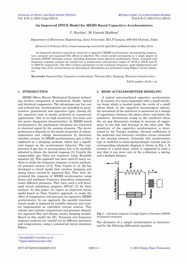
to the sensing element. Generally this accelerometer
type is modeled as mass-spring-damper system and its
corresponding schematic diagram is shown in Fig. 1. It
consists of a proof mass, which is supported in such a
way that it can move only in the x-direction, a spring,
and a dashpot damper.
Fig. 1 – schematic diagram of single degree of freedom (SDOF)
mechanical resonator
The dynamics of a simple accelerometer is character-
ized by the following differential equation
C. KAVITHA, M. GANESH MADHAN J. NANO- ELECTRON. PHYS. 5, 02011 (2013)
02011-2
2
2 ext eld x dxM D kx F F
dtdt (1)
The force (F) is the sum of an external mechanical force
extF and an internal electrical attractive force elF . The electrical attractive force on the mass is caused by the potential difference across the capacitor plates. Assuming the motion perpendicular to the plate surfac-es, the electrostatic force is given as
2
22elAUFd
(2)
where is the dielectric constant of the gas, A is the plate area, U is the capacitor voltage and d is the gap width. The mechanical accelerometer model is realized by the equivalent electrical model of a parallel resonator and is given by the differential equation as
2
21 1
extd dC I
R dt Ldt (3)
where C is the capacitance, is the flux, R is the re-sistance, L is the inductance and Iext is the external current. The displacement equals, LLi , where Li is the current through the inductor.
2.1 Squeezed Film Effect
A Simple linear MEMS capacitive accelerometer
model with viscous gas flow is considered. The struc-ture consists of a mass with cantilever beams and two fixed electrodes [8]. The region between the electrodes may be filled by the damping medium such as gas or liquid. Due to vibrations of proof mass the gas flow in a narrow air gaps will cause damping [9, 10]. The gas pressure inside the sensor can be changed to control the squeezed film effect. The distribution of the gas pressure in the gap between two moving plates is gov-erned by Reynolds equation for a compressible gas film [1, 2]. Assuming isothermal viscous flow behavior be-tween flat surfaces, the linearized Reynolds squeeze film equation is given as
2
2
12a
eff a a
P d p p xP t P t d
(4)
where Pa is the ambient pressure, eff is the effective gas viscosity, 2 is the Laplacian operator, p is a small pressure change of Pa and x is a variation of the plate spacing. Continuum theory is valid for Knudsen num-bers smaller than 0.01 and can be estimated by
nKd
(5)
where nK is the Knudsen number, o o aP P is a mean free path, o is the mean free path at pressure
oP . To consider the slip flow boundary conditions, an effective viscosity is used for the systems to operate at high Knudsen numbers and this model is derived from Boltzmann equation and is calculated [11] by
1.1591 9.638effnK
(6)
where is the viscosity coefficient. These above effects are realized with few Resistance-Inductance (RL) sec-tions in the equivalent circuit representation of squeezed film effect.
4
2
64mna
dL mnAP
(7)
6 3
2 2 2 22768mn
eff
dR mn m c nAw
(8)
where mnL and mnR are inductance and resistance for the squeeze film on air gaps in both sides, which is rep-resented as A and B in a model. m and n are odd in-tegers 1, 3, 5 …. A wl is the rectangular plate area,
/c w l , w and l are the width and length of the mass respectively. Six sections are used in our simula-tions to model both air gaps with odd integers as ((m, n) (1, 1), (1, 3), (3, 1), (3, 3), (1, 5), (5, 1)).
The gas pressure also changes the squeeze number and is given by
2
212 eff
a
wP d
(9)
where is the angular frequency. The accelerometer physical parameters are listed in Table 1.
2.2 Thermo Elastic Damping
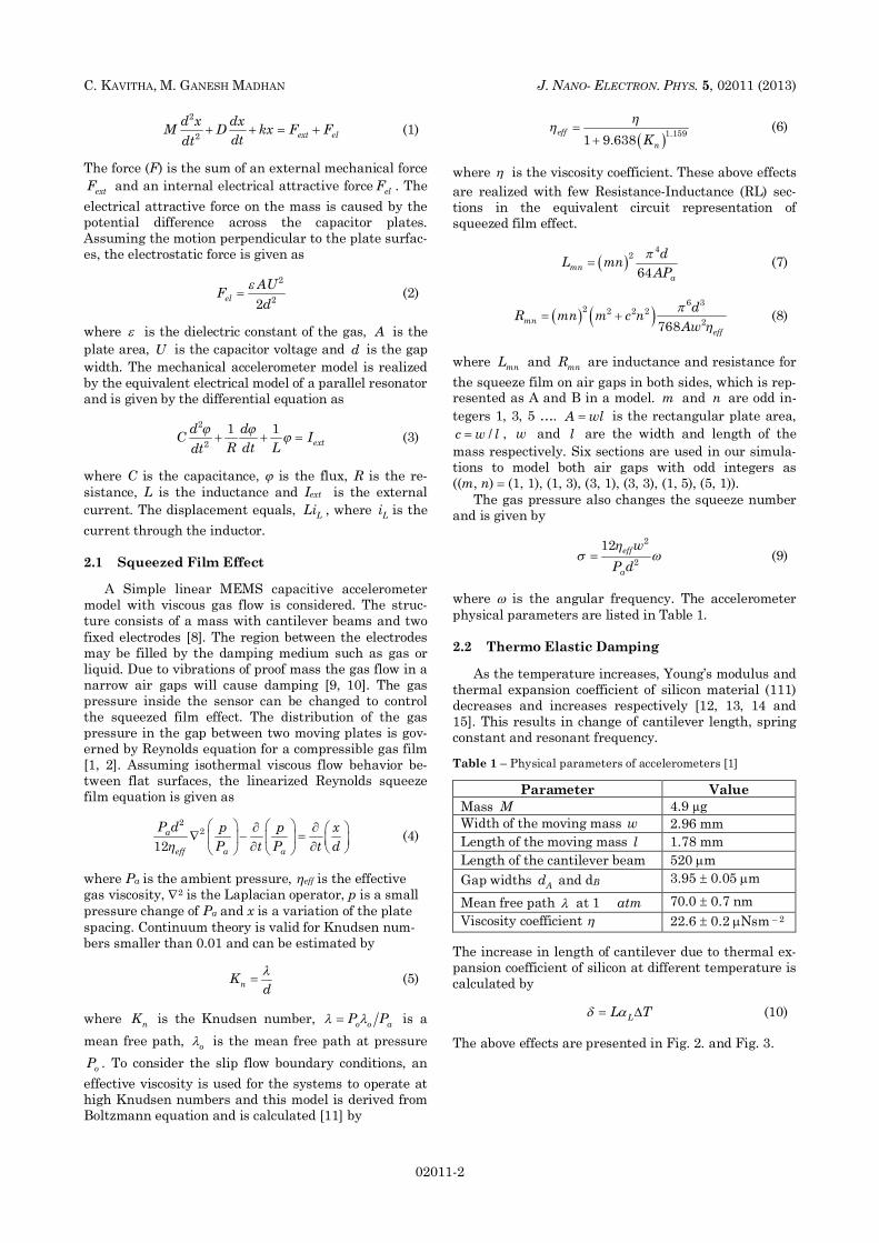
As the temperature increases, Young’s modulus and
thermal expansion coefficient of silicon material (111) decreases and increases respectively [12, 13, 14 and 15]. This results in change of cantilever length, spring constant and resonant frequency.
Table 1 – Physical parameters of accelerometers [1]
Parameter Value
Mass M 4.9 µg Width of the moving mass w 2.96 mm Length of the moving mass l 1.78 mm Length of the cantilever beam 520 m Gap widths Ad and dB 3.95 0.05 m
Mean free path at 1 atm 70.0 0.7 nm Viscosity coefficient 22.6 0.2 Nsm – 2
The increase in length of cantilever due to thermal ex-pansion coefficient of silicon at different temperature is calculated by
LL T (10)
The above effects are presented in Fig. 2. and Fig. 3.
AN IMPROVED SPICE MODEL FOR MEMS … J. NANO- ELECTRON. PHYS. 5, 02011 (2013)
02011-3
Fig. 2 – Thermal effect on stiffness and spring constant
Fig. 3 – Temperature effect on length of cantilever and ther-mal expansion coefficient
Thermal strain and stresses can be estimated as
T L (11)
T TE (12)
where T is the Strain, T is the stress, E is the Young’s Modulus of silicon material. Moment of inertia of the cantilever is obtained by
3
12bhI (13)
where b is the width and h is the thickness of the canti-lever beam. As temperature increases, the spring con-stant reduces as per the following equation [9].
33EIKL
(14)
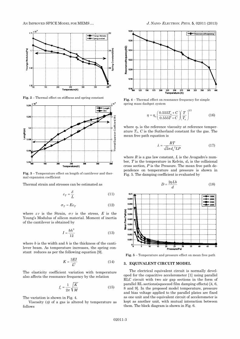
The elasticity coefficient variation with temperature also affects the resonance frequency by the relation
12r
KfM
(15)
The variation is shown in Fig. 4. Viscosity ( ) of a gas is altered by temperature as
follows
Fig. 4 – Thermal effect on resonance frequency for simple spring mass dashpot system
3 2
0.5550.555
oo
o
T C TT C T
(16)
where o is the reference viscosity at reference temper-ature To, C is the Sutherland constant for the gas. The mean free path equation is
22 a
RTd LP
(17)
where R is a gas law constant, L is the Avagadro’s num-ber, T is the temperature in Kelvin, da is the collisional cross section, P is the Pressure. The mean free path de-pendence on temperature and pressure is shown in Fig. 5. The damping coefficient is evaluated by
2 LbDd
(18)
Fig. 5 – Temperature and pressure effect on mean free path
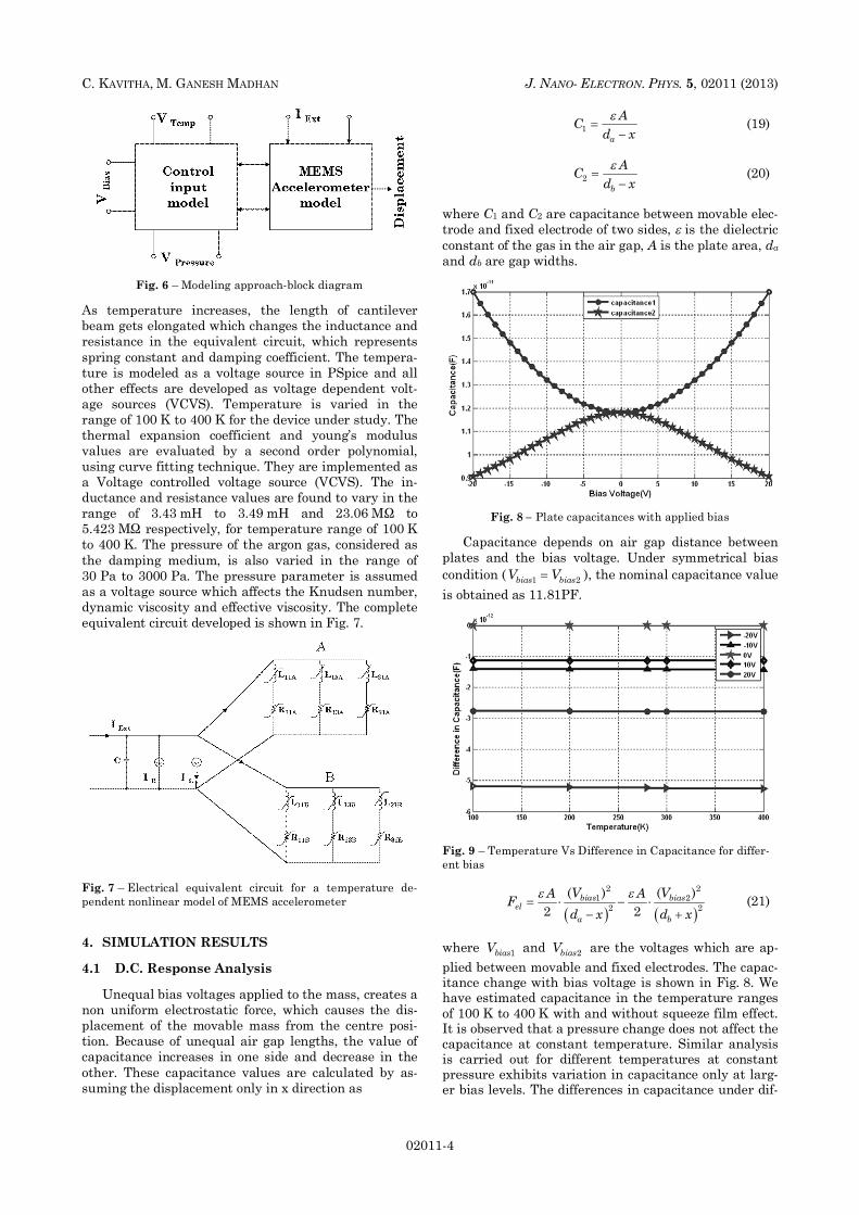
3. EQUIVALENT CIRCUIT MODEL The electrical equivalent circuit is normally devel-
oped for the capacitive accelerometer [1] using parallel RLC circuit with two air gap sections in the form of parallel RL sections(squeezed film damping effects) [4, 6, 8 and 9]. In the proposed model temperature, pressure and bias voltage applied to the parallel plates are fixed as one unit and the equivalent circuit of accelerometer is kept as another unit, with mutual interaction between them. The block diagram is shown in Fig. 6.
C. KAVITHA, M. GANESH MADHAN J. NANO- ELECTRON. PHYS. 5, 02011 (2013)
02011-4
Fig. 6 – Modeling approach-block diagram
As temperature increases, the length of cantilever beam gets elongated which changes the inductance and resistance in the equivalent circuit, which represents spring constant and damping coefficient. The tempera-ture is modeled as a voltage source in PSpice and all other effects are developed as voltage dependent volt-age sources (VCVS). Temperature is varied in the range of 100 K to 400 K for the device under study. The thermal expansion coefficient and young’s modulus values are evaluated by a second order polynomial, using curve fitting technique. They are implemented as a Voltage controlled voltage source (VCVS). The in-ductance and resistance values are found to vary in the range of 3.43 mH to 3.49 mH and 23.06 M to 5.423 M respectively, for temperature range of 100 K to 400 K. The pressure of the argon gas, considered as the damping medium, is also varied in the range of 30 Pa to 3000 Pa. The pressure parameter is assumed as a voltage source which affects the Knudsen number, dynamic viscosity and effective viscosity. The complete equivalent circuit developed is shown in Fig. 7.
Fig. 7 – Electrical equivalent circuit for a temperature de-pendent nonlinear model of MEMS accelerometer 4. SIMULATION RESULTS
4.1 D.C. Response Analysis
Unequal bias voltages applied to the mass, creates a
non uniform electrostatic force, which causes the dis-placement of the movable mass from the centre posi-tion. Because of unequal air gap lengths, the value of capacitance increases in one side and decrease in the other. These capacitance values are calculated by as-suming the displacement only in x direction as
1a
ACd x
(19)
2b
ACd x
(20)
where C1 and C2 are capacitance between movable elec-trode and fixed electrode of two sides, is the dielectric constant of the gas in the air gap, A is the plate area, da and db are gap widths.
Fig. 8 – Plate capacitances with applied bias Capacitance depends on air gap distance between
plates and the bias voltage. Under symmetrical bias condition ( 1 2bias biasV V ), the nominal capacitance value is obtained as 11.81PF.
Fig. 9 – Temperature Vs Difference in Capacitance for differ-ent bias
2 2
1 22 2
( ) ( )2 2
bias biasel
a b
V VA AFd x d x
(21)
where 1biasV and 2biasV are the voltages which are ap-plied between movable and fixed electrodes. The capac-itance change with bias voltage is shown in Fig. 8. We have estimated capacitance in the temperature ranges of 100 K to 400 K with and without squeeze film effect. It is observed that a pressure change does not affect the capacitance at constant temperature. Similar analysis is carried out for different temperatures at constant pressure exhibits variation in capacitance only at larg-er bias levels. The differences in capacitance under dif-
AN IMPROVED SPICE MODEL FOR MEMS … J. NANO- ELECTRON. PHYS. 5, 02011 (2013)
02011-5
ferent bias conditions are shown in Fig. 9.
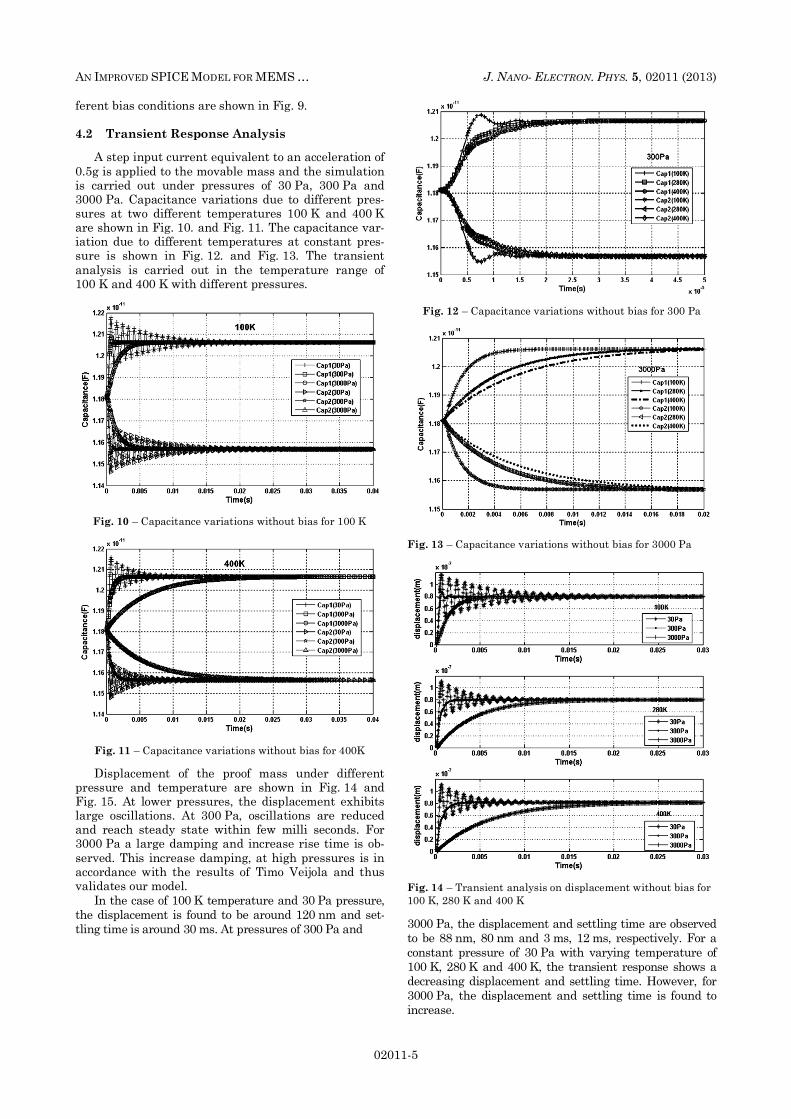
4.2 Transient Response Analysis A step input current equivalent to an acceleration of
0.5g is applied to the movable mass and the simulation is carried out under pressures of 30 Pa, 300 Pa and 3000 Pa. Capacitance variations due to different pres-sures at two different temperatures 100 K and 400 K are shown in Fig. 10. and Fig. 11. The capacitance var-iation due to different temperatures at constant pres-sure is shown in Fig. 12. and Fig. 13. The transient analysis is carried out in the temperature range of 100 K and 400 K with different pressures.
Fig. 10 – Capacitance variations without bias for 100 K
Fig. 11 – Capacitance variations without bias for 400K Displacement of the proof mass under different
pressure and temperature are shown in Fig. 14 and Fig. 15. At lower pressures, the displacement exhibits large oscillations. At 300 Pa, oscillations are reduced and reach steady state within few milli seconds. For 3000 Pa a large damping and increase rise time is ob-served. This increase damping, at high pressures is in accordance with the results of Timo Veijola and thus validates our model.
In the case of 100 K temperature and 30 Pa pressure, the displacement is found to be around 120 nm and set-tling time is around 30 ms. At pressures of 300 Pa and
Fig. 12 – Capacitance variations without bias for 300 Pa
Fig. 13 – Capacitance variations without bias for 3000 Pa
Fig. 14 – Transient analysis on displacement without bias for 100 K, 280 K and 400 K 3000 Pa, the displacement and settling time are observed to be 88 nm, 80 nm and 3 ms, 12 ms, respectively. For a constant pressure of 30 Pa with varying temperature of 100 K, 280 K and 400 K, the transient response shows a decreasing displacement and settling time. However, for 3000 Pa, the displacement and settling time is found to increase.
C. KAVITHA, M. GANESH MADHAN J. NANO- ELECTRON. PHYS. 5, 02011 (2013)
02011-6
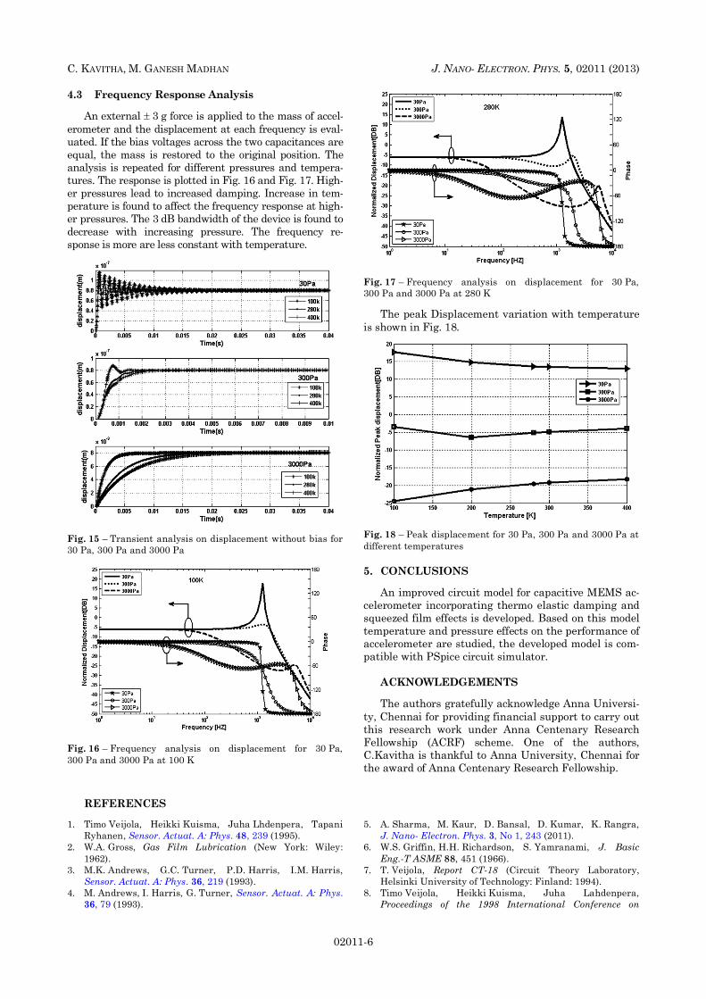
4.3 Frequency Response Analysis An external 3 g force is applied to the mass of accel-
erometer and the displacement at each frequency is eval-uated. If the bias voltages across the two capacitances are equal, the mass is restored to the original position. The analysis is repeated for different pressures and tempera-tures. The response is plotted in Fig. 16 and Fig. 17. High-er pressures lead to increased damping. Increase in tem-perature is found to affect the frequency response at high-er pressures. The 3 dB bandwidth of the device is found to decrease with increasing pressure. The frequency re-sponse is more are less constant with temperature.
Fig. 15 – Transient analysis on displacement without bias for 30 Pa, 300 Pa and 3000 Pa
Fig. 16 – Frequency analysis on displacement for 30 Pa, 300 Pa and 3000 Pa at 100 K
Fig. 17 – Frequency analysis on displacement for 30 Pa, 300 Pa and 3000 Pa at 280 K
The peak Displacement variation with temperature
is shown in Fig. 18.
Fig. 18 – Peak displacement for 30 Pa, 300 Pa and 3000 Pa at different temperatures
5. CONCLUSIONS
An improved circuit model for capacitive MEMS ac-
celerometer incorporating thermo elastic damping and squeezed film effects is developed. Based on this model temperature and pressure effects on the performance of accelerometer are studied, the developed model is com-patible with PSpice circuit simulator.
ACKNOWLEDGEMENTS The authors gratefully acknowledge Anna Universi-
ty, Chennai for providing financial support to carry out this research work under Anna Centenary Research Fellowship (ACRF) scheme. One of the authors, C.Kavitha is thankful to Anna University, Chennai for the award of Anna Centenary Research Fellowship.
REFERENCES
1. Timo Veijola, Heikki Kuisma, Juha Lhdenpera, Tapani Ryhanen, Sensor. Actuat. A: Phys. 48, 239 (1995).
2. W.A. Gross, Gas Film Lubrication (New York: Wiley: 1962).
3. M.K. Andrews, G.C. Turner, P.D. Harris, I.M. Harris, Sensor. Actuat. A: Phys. 36, 219 (1993).
4. M. Andrews, I. Harris, G. Turner, Sensor. Actuat. A: Phys. 36, 79 (1993).
5. A. Sharma, M. Kaur, D. Bansal, D. Kumar, K. Rangra, J. Nano- Electron. Phys. 3, No 1, 243 (2011).
6. W.S. Griffin, H.H. Richardson, S. Yamranami, J. Basic Eng.-T ASME 88, 451 (1966).
7. T. Veijola, Report CT-18 (Circuit Theory Laboratory, Helsinki University of Technology: Finland: 1994).
8. Timo Veijola, Heikki Kuisma, Juha Lahdenpera, Proceedings of the 1998 International Conference on
AN IMPROVED SPICE MODEL FOR MEMS … J. NANO- ELECTRON. PHYS. 5, 02011 (2013)
02011-7
Modeling and Simulation of Microsystems – MSM’98, Santa Clara, 245 (Boston: Computational: 1998).
9. Timo Veijola, Tapani Ryhanen, IEEE International Sym-posium on Circuits and Systems – ISCAS'95, 664 (Pisca-taway, NJ: IEEE: 1995).
10. C. Bourgeois, F. Porret, A. Hoogerwerf, The 1997 Internafional Conference on Solid-State Sensors and Actuators – Tranducers'97 Chicago, 1117 (Piscataway, NJ: IEEE: 1997).
11. S. Fukui, R. Kaneko, J. Tribol-T. ASME 110, 262 (1988). 12. M.J. Edwards, C.R. Bowen, D.W.E. Allsopp, A.C.E. Dent,
J. Phys. D: Appl. Phys. 43, 385502 (2010). 13. Gang Dai, Mei Li, Xiaoping He, Lianming Du,
Beibei Shao, Wei Su, Sensor. Actuat. A: Phys. 172, 369 (2011).
14. Jeung-Hyun Jeong, Sung-Hoon Chung, Se-Ho-Lee, Dongil Kwon, J. Microelectromech. Syst. 12, 524 (2003).
15. Jing Wang, Qing-An Huang, Hong Yu, J. Phys. D: Appl. Phys. 41, 165406 (2008)