burndy electrical connection reference
DESCRIPTION
Burndy Electrical Connectors Reference GuideTRANSCRIPT
BURNDYReference
O-1
TABLE OF CONTENTS
Compact ACSR Cable ................................O-15
ACSR/TW Cable (Trap Wire)...........O-15 - O-16
AAC/TW Cable (All aluminum trap wire)............................O-16
ACAR Cable ...............................................O-16
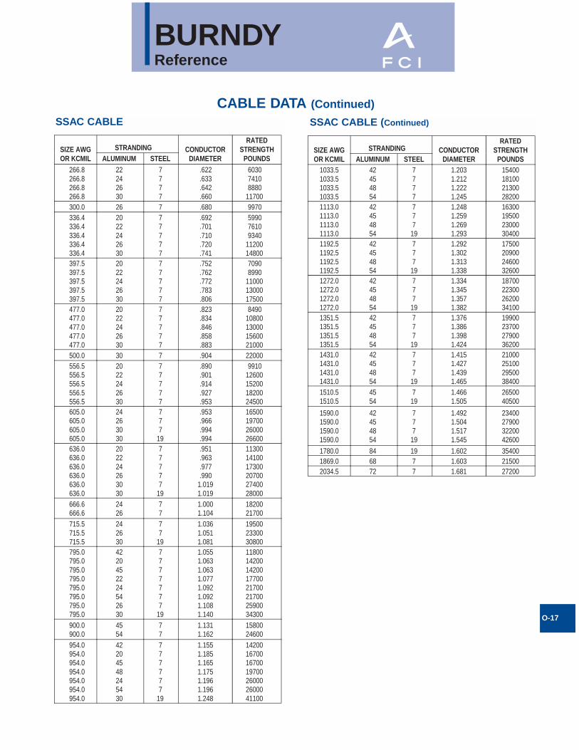
SSAC Cable................................................O-17
STEEL CONDUCTORS
Copperweld Cable ......................................O-18
Copperweld - Copper Cable .......................O-18
Galvanized Steel Cable ..............................O-18
Alumoweld Cable........................................O-19
AWG vs Metric Wire Sizes .......................O-19
Inches - MillimetersConversion Chart....................................O-20
Terminal Stud Size Chart .........................O-21
Die Set Conversion Chart (Obsolete Dies) ............................O-22 - O-28
BURNDY® Conductor Numbering System .....................O-29 - O-30
Installation Tool Index ...................O-31 - O-41
Catalog Numbers Requiring MSDS .....................................O-42
Color Coding for OverheadConnectors ..............................................O-42
Color Coding for AL/CU Connectors..................................O-43
Color Coding for Copper Lugs and Splices ....................................O-43
Alpha-Numeric Index ....................O-44 - O-67
Product/Trade Name Index ......................O-68
INTRODUCTION
Basic Connection Principles .........................O-2
HARDWARE DATA
DURIUM™ Steel/Aluminum Tightening Torques .....................................O-6
DURIUM™ Hex Bolts Data...........................O-6
UL Tightening Torque UL486........................O-7
CABLE DATA (TABLES)COPPER CABLE
Copper Tube .................................................O-8
Solid Copper Wire.........................................O-8
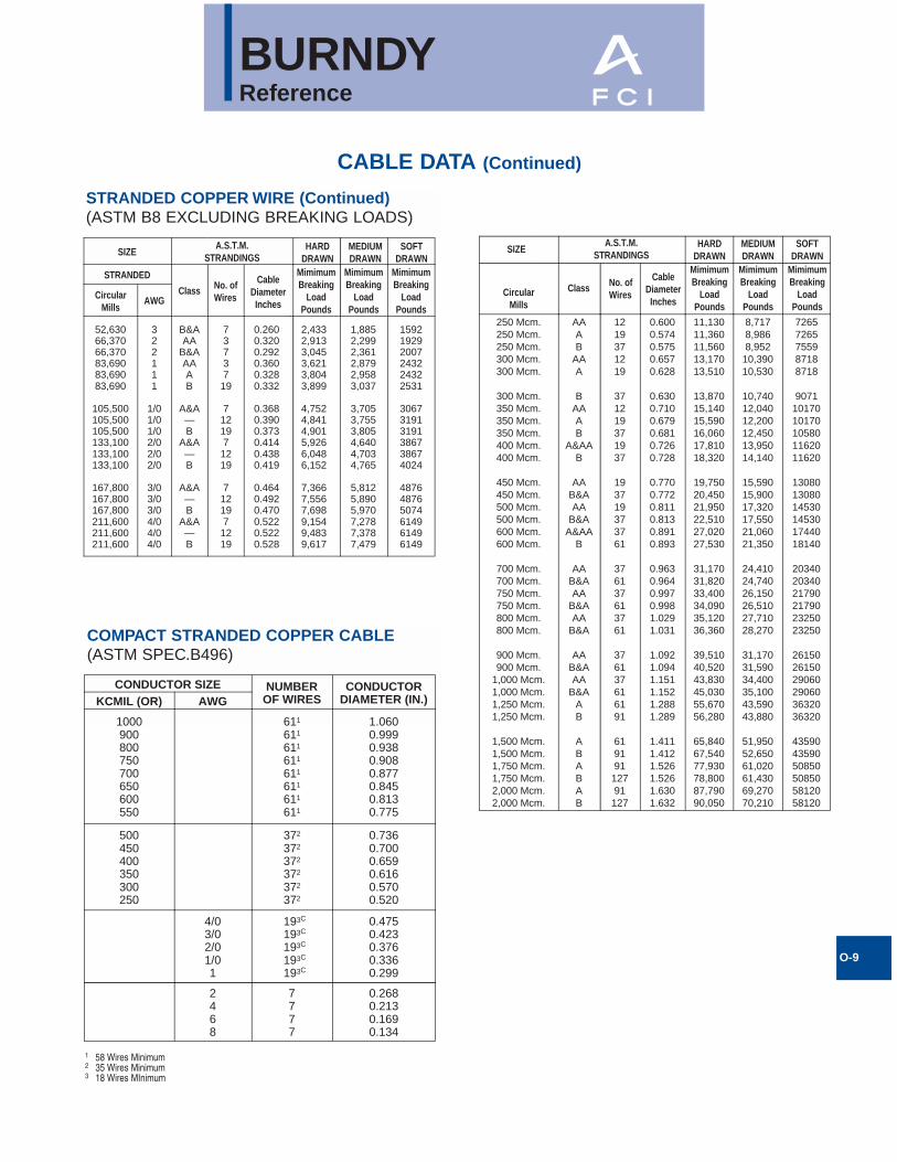
Stranded Copper Cable................................O-8
Compact Stranded Copper Cable ................O-9
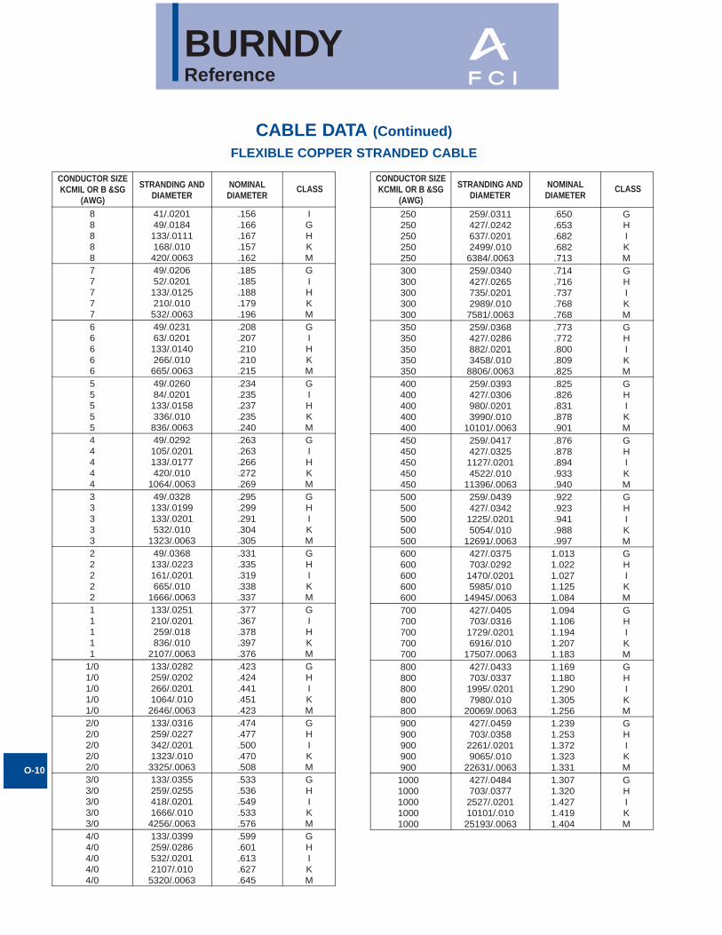
Flexible Copper Stranded Cable.................O-10
ALUMINUM AND ACSR CABLE
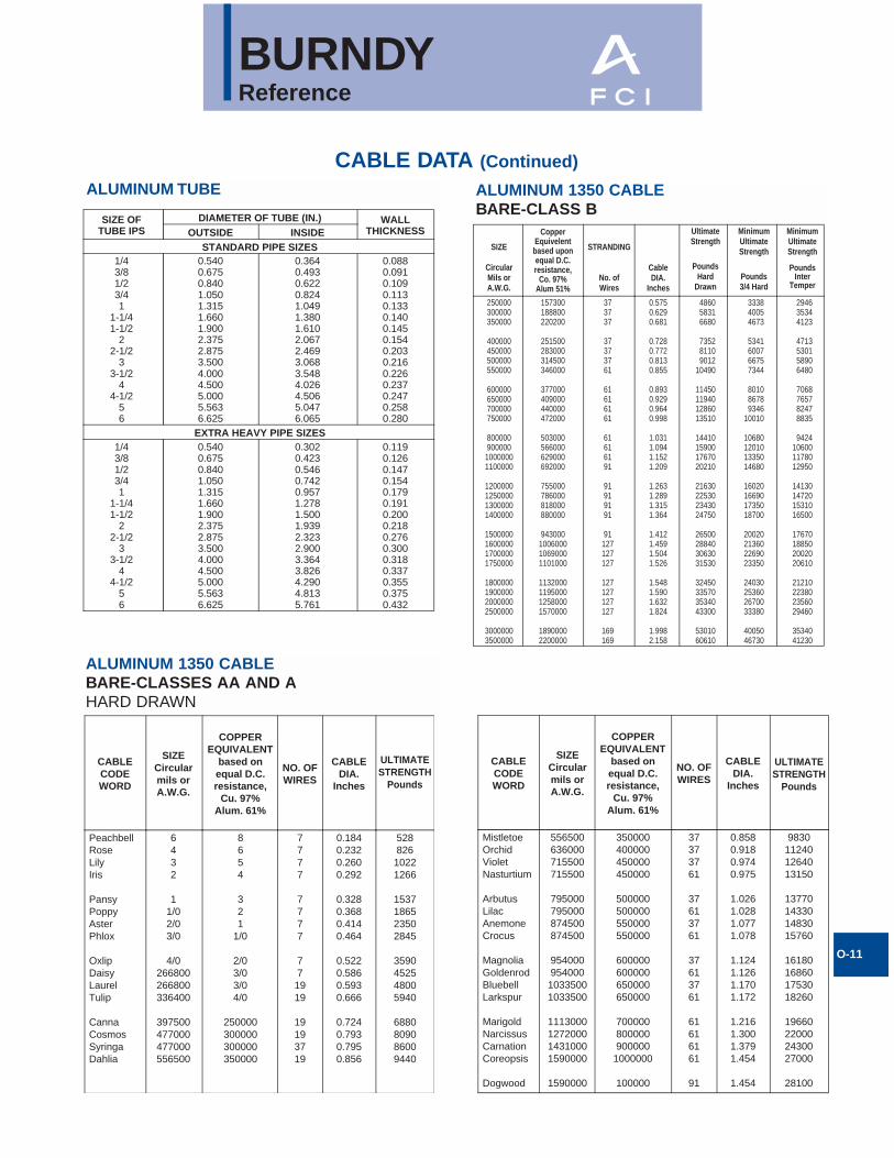
Aluminum Tube ...........................................O-11
Aluminum 1350 Cable
Bare-Classes AA and A..........................O-11
Aluminum 1350 Cable
Bare-Class B ..........................................O-11
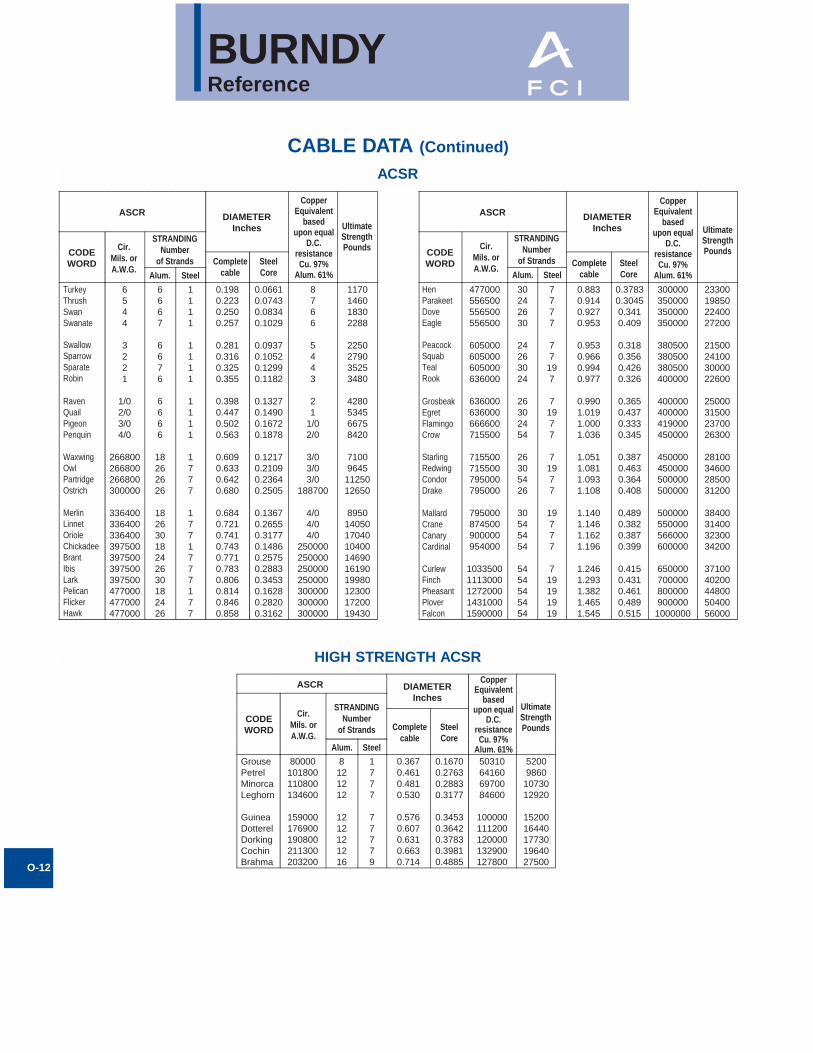
ACSR Cable ...............................................O-12
High Strength ACSR Cable ........................O-12
Compact Aluminum 1350 Cable.................O-13
Aluminum Alloy 5005 Cable .......................O-13
Aluminum 6201 Cable ................................O-13
Aluminum Alloy 8000 Series "O"Temper Cable ................................O-14 - O-15
BURNDYReference
BASIC ELECTRICALCONNECTION PRINCIPLES
Basic Factors:The basic factors which influence the designand performance of pressure wire connec-tions are as follows:
1. Creep2. Surface Oxide3. Corrosion
A fourth factor, known as thermal effects, isalso a consideration, but due to the technicalnature and length of the topic, it will not bediscussed in this publication.
At the outset it should be pointed out thatthese factors give rise to much more difficultproblems in connections involving aluminumconductors than those encountered in copperto copper connections.
CREEP (COLD FLOW)Creep is the cold flow of the metal underpressure, and it continues until the pressurereduces to a value at which any further creepis negligible. Creep properties depend on theparticular metal or alloy and on its hardness;alloys having less creep than pure metals,and harder metals have less creep than softmetals. In a typical connection, the conduc-tors are generally of pure metal and often ofsoft temper and therefore, subject to consid-erable creep. In addition, the condition isfurther exaggerated when aluminum is theconductor as compared to copper, since itscreep rate is many times that of copper.
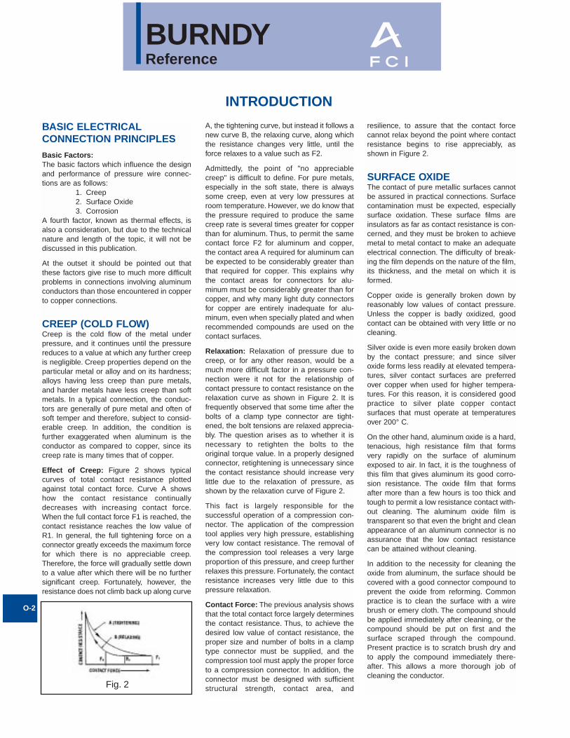
Effect of Creep: Figure 2 shows typicalcurves of total contact resistance plottedagainst total contact force. Curve A showshow the contact resistance continuallydecreases with increasing contact force.When the full contact force F1 is reached, thecontact resistance reaches the low value ofR1. In general, the full tightening force on aconnector greatly exceeds the maximum forcefor which there is no appreciable creep.Therefore, the force will gradually settle downto a value after which there will be no furthersignificant creep. Fortunately, however, theresistance does not climb back up along curve
A, the tightening curve, but instead it follows anew curve B, the relaxing curve, along whichthe resistance changes very little, until theforce relaxes to a value such as F2.
Admittedly, the point of "no appreciablecreep" is difficult to define. For pure metals,especially in the soft state, there is alwayssome creep, even at very low pressures atroom temperature. However, we do know thatthe pressure required to produce the samecreep rate is several times greater for copperthan for aluminum. Thus, to permit the samecontact force F2 for aluminum and copper,the contact area A required for aluminum canbe expected to be considerably greater thanthat required for copper. This explains whythe contact areas for connectors for alu-minum must be considerably greater than forcopper, and why many light duty connectorsfor copper are entirely inadequate for alu-minum, even when specially plated and whenrecommended compounds are used on thecontact surfaces.
Relaxation: Relaxation of pressure due tocreep, or for any other reason, would be amuch more difficult factor in a pressure con-nection were it not for the relationship ofcontact pressure to contact resistance on therelaxation curve as shown in Figure 2. It isfrequently observed that some time after thebolts of a clamp type connector are tight-ened, the bolt tensions are relaxed apprecia-bly. The question arises as to whether it isnecessary to retighten the bolts to theoriginal torque value. In a properly designedconnector, retightening is unnecessary sincethe contact resistance should increase verylittle due to the relaxation of pressure, asshown by the relaxation curve of Figure 2.
This fact is largely responsible for thesuccessful operation of a compression con-nector. The application of the compressiontool applies very high pressure, establishingvery low contact resistance. The removal ofthe compression tool releases a very largeproportion of this pressure, and creep furtherrelaxes this pressure. Fortunately, the contactresistance increases very little due to thispressure relaxation.
Contact Force: The previous analysis showsthat the total contact force largely determinesthe contact resistance. Thus, to achieve thedesired low value of contact resistance, theproper size and number of bolts in a clamptype connector must be supplied, and thecompression tool must apply the proper forceto a compression connector. In addition, theconnector must be designed with sufficientstructural strength, contact area, and
resilience, to assure that the contact forcecannot relax beyond the point where contactresistance begins to rise appreciably, asshown in Figure 2.
SURFACE OXIDEThe contact of pure metallic surfaces cannotbe assured in practical connections. Surfacecontamination must be expected, especiallysurface oxidation. These surface films areinsulators as far as contact resistance is con-cerned, and they must be broken to achievemetal to metal contact to make an adequateelectrical connection. The difficulty of break-ing the film depends on the nature of the film,its thickness, and the metal on which it isformed.
Copper oxide is generally broken down byreasonably low values of contact pressure.Unless the copper is badly oxidized, goodcontact can be obtained with very little or nocleaning.
Silver oxide is even more easily broken downby the contact pressure; and since silveroxide forms less readily at elevated tempera-tures, silver contact surfaces are preferredover copper when used for higher tempera-tures. For this reason, it is considered goodpractice to silver plate copper contactsurfaces that must operate at temperaturesover 200° C.
On the other hand, aluminum oxide is a hard,tenacious, high resistance film that formsvery rapidly on the surface of aluminumexposed to air. In fact, it is the toughness ofthis film that gives aluminum its good corro-sion resistance. The oxide film that formsafter more than a few hours is too thick andtough to permit a low resistance contact with-out cleaning. The aluminum oxide film istransparent so that even the bright and cleanappearance of an aluminum connector is noassurance that the low contact resistancecan be attained without cleaning.
In addition to the necessity for cleaning theoxide from aluminum, the surface should becovered with a good connector compound toprevent the oxide from reforming. Commonpractice is to clean the surface with a wirebrush or emery cloth. The compound shouldbe applied immediately after cleaning, or thecompound should be put on first and thesurface scraped through the compound.Present practice is to scratch brush dry andto apply the compound immediately there-after. This allows a more thorough job ofcleaning the conductor.
O-2
Fig. 2
INTRODUCTION
BURNDYReference
Contact Compounds: Petrolatum or No-Oxid are good contact surface compoundsfor aluminum, but BURNDY PENETROX A, apetrolatum type compound containing zincdust, has the additional advantage of assist-ing in the breaking down of the contact resis-tance. How this is accomplished is notcertain, but it appears that the zinc particlesof PENETROX A probably act as currentbridges in the breaks in the oxide film. Formore complete information about the PENE-TROX® line of compounds, refer to theAccessories Section of this catalog.
Interstrand Resistance: The high contactresistance due to the oxide on the strands ofan aluminum cable may be responsible for apoor distribution of current among the strandson the cable. Thus, the outer strands maycarry much more than their share of thecurrent and overheating of the cable mayresult. Tests have shown that even on newcable this effect of interstrand resistance canbe considerable unless a good contactcompound is used. The clamping actiontends to break down the oxide and force thecompound between the strands. This is par-ticularly true of compression connectors dueto the very high unit pressures developed.
The most effective way to break down inter-strand resistance of aluminum cable is to usecompression connectors filled with a com-pound having zinc particles. Then, when theend of the cable is inserted in the connector,the compound is forced between the strandswhere it very effectively breaks down theinterstrand resistance upon application of thecompressive force.
Plating Aluminum: Plating the contact sur-faces of aluminum connectors will prevent theformation of aluminum oxide. Electro-tin,cadmium and zinc platings have been usedfor this purpose. However, the use of a platedaluminum conductor, does not make it lessnecessary to scratch brush the aluminumconductor, nor does it reduce the need for agood contact compound. Additional problemsare introduced due to the plating onaluminum which render it of very doubtfulvalue over the proper use of bare aluminum.This will be more fully discussed later.
CORROSIONThe electrical conductivity and mechanicalstrength of an electrical connection mustremain stable under the deteriorating influ-ences of the environment. This deteriorationis corrosion. It is the electrolytic action ofmoisture and other elements of the atmos-phere in conjunction with the metals of the
connection. If the conductors and connectorsare of copper or a corrosion resistant copperalloy, corrosion is usually a minor factor.However, it is a very vital factor if aluminum is involved.
If moisture can be kept away from the con-nection, corrosion will not be a factor. Theelectrical connection of a high voltage spliceon insulated cable is generally free fromcorrosion since the taping must be moisture-proof. Similarly, taping may be used to avoidcorrosion on bare cable, provided it excludesmoisture. It is difficult to get a good tape sealto the conductor itself, especially on strandedcable. If moisture does penetrate the taping, itwill not dry out as readily as if the joint wereuntaped. Various plastic materials are avail-able today for covering low voltage connec-tions or for bare conductor connections onhigh voltage. Unless such coverings are completely moisture-proof, it is better to rely on installation with a good contact compound, using a connector designed to resist corrosion.
Galvanic Action: Whenever dissimilarmetals are in the presence of an electrolyte, adifference in electric potential is developed.One metal becomes the cathode andreceives a positive charge. The otherbecomes the anode and receives a negativecharge. When these metals are in contact, anelectrical current will flow, as in the case ofany short-circuited electric cell. This elec-trolytic action causes an attack of the anodicmetal, leaving the cathodic metal unharmed.The extent of the attack is proportional to thestrength of the electrolytic current, which inturn is proportional to the electric potential difference developed.
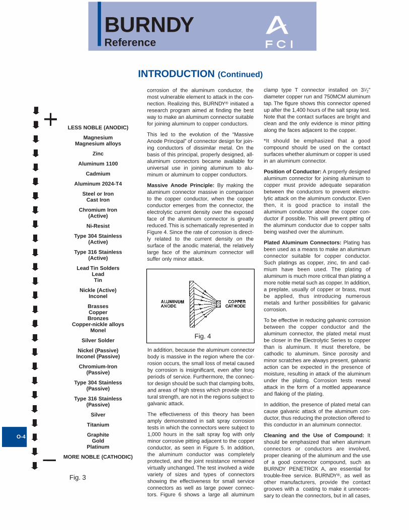
The magnitude of the potential differencegenerated between two dissimilar metals canbe seen by the position of these metals in theelectrolytic series. Figure 3 is such a series.When two metals are in contact in an elec-trolyte, the one higher up in this series is theanode, the corroded metal, while the onelower is the cathode, the protected metal. Thefurther apart the metals are in this series, the greater the electrolytic potential differ-ence, and the greater the attack to the anodic metal.
Note that copper and aluminum are quite farapart in the series, copper being cathodic andaluminum anodic. Hence, when aluminumand copper are in contact in an electrolyte,the aluminum can be expected to be severely attacked.
Crevice Corrosion: Electrolytic attack canalso occur between like metals due to aphenomenon known as oxygen concentrationcell or crevice corrosion. Since oxygen isnecessary for corrosive action, a variation inthe concentration of oxygen where a metal isexposed to an electrolyte will generate adifference of potential, and cause a corrosiveattack in the oxygen starved area. Thus,since an electrolyte in a deep crevice is freelyexposed to the air at the outside, the concen-tration of oxygen will be greatest at the mouthof the crevice. Then corrosion can be expect-ed to occur in the crevice remote from thesurface. Crevice corrosion can be preventedif the crevice is filled with a compound toexclude moisture. Thus, within the contactgroove of an aluminum connector containingan aluminum conductor, there will be numer-ous crevices in which corrosion will takeplace unless a good connector compound isapplied during installation. Copper, being amore noble metal, appears to be much lesssubject to crevice corrosion.
Corrosion Testing: The effectiveness of anelectrical connection to resist corrosion canbe tested in the laboratory under conditionsdesigned to greatly accelerate the naturalcorrosive conditions of actual service. Themost widely accepted means is the standardsalt spray chamber. In this chamber the spec-imens are placed in a salt fog made by atom-izing a 20% salt solution at 100 deg F.
FCI - BURNDY Electrical as well as othermanufacturers and utility companies, havedone a great deal of testing and a consider-able area of agreement has been reached.There are, however, minor differences in recommended practices. The problem is concerned with aluminum and aluminum tocopper connections since the effect of corro-sion on copper to copper connections is far less serious. Let us study the recommendedpractices.
Aluminum to Aluminum Connections: Forjoining aluminum to aluminum conductors,there is little disagreement that an aluminumbodied connector is the proper choice, sincethis obviously eliminates the galvanic corro-sion of dissimilar metals. However, even inthis case, care must be taken to preventcrevice corrosion and to select an alloy of aluminum for the connector body that is freefrom cracking due to stress corrosion.
Aluminum to Copper Connections:Similarly, for joining aluminum to copperconductors, an aluminum bodied connector isthe best choice since it prevents galvanic
O-3
INTRODUCTION (Continued)
BURNDYReference
corrosion of the aluminum conductor, themost vulnerable element to attack in the con-nection. Realizing this, BURNDY® initiated aresearch program aimed at finding the bestway to make an aluminum connector suitablefor joining aluminum to copper conductors.
This led to the evolution of the “MassiveAnode Principal” of connector design for join-ing conductors of dissimilar metal. On thebasis of this principal, properly designed, all-aluminum connectors became available foruniversal use in joining aluminum to alu-minum or aluminum to copper conductors.
Massive Anode Principle: By making thealuminum connector massive in comparisonto the copper conductor, when the copperconductor emerges from the connector, theelectrolytic current density over the exposedface of the aluminum connector is greatlyreduced. This is schematically represented inFigure 4. Since the rate of corrosion is direct-ly related to the current density on thesurface of the anodic material, the relativelylarge face of the aluminum connector willsuffer only minor attack.
In addition, because the aluminum connectorbody is massive in the region where the cor-rosion occurs, the small loss of metal causedby corrosion is insignificant, even after longperiods of service. Furthermore, the connec-tor design should be such that clamping bolts,and areas of high stress which provide struc-tural strength, are not in the regions subject togalvanic attack.
The effectiveness of this theory has beenamply demonstrated in salt spray corrosiontests in which the connectors were subject to1,000 hours in the salt spray fog with onlyminor corrosive pitting adjacent to the copperconductor, as seen in Figure 5. In addition,the aluminum conductor was completelyprotected, and the joint resistance remainedvirtually unchanged. The test involved a widevariety of sizes and types of connectorsshowing the effectiveness for small serviceconnectors as well as large power connec-tors. Figure 6 shows a large all aluminum
clamp type T connector installed on 31⁄2"diameter copper run and 750MCM aluminumtap. The figure shows this connector openedup after the 1,400 hours of the salt spray test.Note that the contact surfaces are bright andclean and the only evidence is minor pittingalong the faces adjacent to the copper.
*It should be emphasized that a goodcompound should be used on the contactsurfaces whether aluminum or copper is usedin an aluminum connector.
Position of Conductor: A properly designedaluminum connector for joining aluminum tocopper must provide adequate separationbetween the conductors to prevent electro-lytic attack on the aluminum conductor. Eventhen, it is good practice to install thealuminum conductor above the copper con-ductor if possible. This will prevent pitting ofthe aluminum conductor due to copper saltsbeing washed over the aluminum.
Plated Aluminum Connectors: Plating hasbeen used as a means to make an aluminumconnector suitable for copper conductor.Such platings as copper, zinc, tin and cad-mium have been used. The plating ofaluminum is much more critical than plating amore noble metal such as copper. In addition,a preplate, usually of copper or brass, must be applied, thus introducing numerous metals and further possibilities for galvaniccorrosion.
To be effective in reducing galvanic corrosionbetween the copper conductor and thealuminum connector, the plated metal mustbe closer in the Electrolytic Series to copperthan is aluminum. It must therefore, becathodic to aluminum. Since porosity andminor scratches are always present, galvanicaction can be expected in the presence ofmoisture, resulting in attack of the aluminumunder the plating. Corrosion tests revealattack in the form of a mottled appearanceand flaking of the plating.
In addition, the presence of plated metal cancause galvanic attack of the aluminum con-ductor, thus reducing the protection offered tothis conductor in an aluminum connector.
Cleaning and the Use of Compound: Itshould be emphasized that when aluminumconnectors or conductors are involved,proper cleaning of the aluminum and the useof a good connector compound, such asBURNDY PENETROX A, are essential fortrouble-free service. BURNDY®, as well asother manufacturers, provide the contactgrooves with a coating to make it unneces-sary to clean the connectors, but in all cases,
O-4
INTRODUCTION (Continued)
Fig. 3
Fig. 4
LESS NOBLE (ANODIC)
MagnesiumMagnesium alloys
Zinc
Aluminum 1100
Cadmium
Aluminum 2024-T4
Steel or IronCast Iron
Chromium Iron(Active)
Ni-Resist
Type 304 Stainless(Active)
Type 316 Stainless(Active)
Lead Tin Solders LeadTin
Nickle (Active)Inconel
BrassesCopperBronzes
Copper-nickle alloysMonel
Silver Solder
Nickel (Passive)Inconel (Passive)
Chromium-Iron(Passive)
Type 304 Stainless(Passive)
Type 316 Stainless(Passive)
Silver
Titanium
GraphiteGold
Platinum
MORE NOBLE (CATHODIC)
BURNDYReference
the aluminum conductor should be cleanedby means such as scratch brushing, andimmediately coated with the connectorcompound.
To simplify the application of the compound,and to assure its use, almost all BURNDY®
aluminum connectors, except the large clamptype substation connectors, are suppliedfactory filled with PENETROX® compound.For the tubular compression connectors, thetubular barrels are sufficiently filled withPENETROX® and capped. For other types,the contact grooves are filled with PENE-TROX® and enclosed in plastic packaging ina process called “Stripsealing”.
Clamp vs. Compression: In general, acompression connection can be expected tobe more corrosion resistant than a clampconnection. The high pressures applied in acompression connector more effectively sealthe contact against the penetration of mois-ture. The tubular sleeve of a compressionconnector has no side openings such as existin clamp connectors between the clampingmembers. On the other hand, the clampconnector can be made more corrosion resis-tant if the conductor grooves conform moreclosely with the conductor contour. Thus aclamp connector made to accommodate awide range of conductor sizes cannot beexpected to be as corrosion resistant as onedesigned for one specific conductor size.Nevertheless, the differences in effectivenessof various designs can be minimized if a goodcontact compound is used.
O-5
INTRODUCTION (Continued)
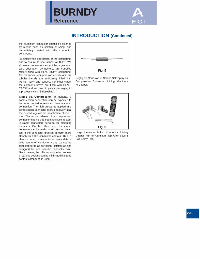
Fig. 5
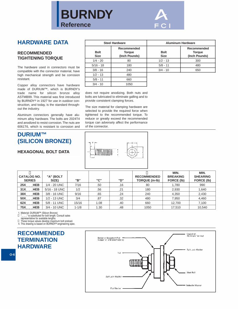
Fig. 6
Negligible Corrosion of Severe Salt Spray onCompression Connector Joining Aluminum to Copper.
Large Aluminum Bolted Connector JoiningCopper Run to Aluminum Tap After SevereSalt Spray Test.
BURNDYReference
HARDWARE DATA
RECOMMENDEDTIGHTENING TORQUE
The hardware used in connectors must becompatible with the connector material, havehigh mechanical strength and be corrosionresistant.
Copper alloy connectors have hardwaremade of DURIUM™, which is BURNDY'strade name for silicon bronze alloyASTMB99. This material was first introducedby BURNDY® in 1927 for use in outdoor con-struction, and today, is the standard through-out the industry.
Aluminum connectors generally have alu-minum alloy hardware. The bolts are 2024T4and anodized to resist corrosion. The nuts are6061T6, which is resistant to corrosion and
does not require anodizing. Both nuts andbolts are lubricated to eliminate galling and toprovide consistent clamping forces.
The size material for clamping hardware areselected to provide the required force whentightened to the recommended torque. Toreduce or greatly exceed the recommendedtorque can adversely affect the performanceof the connector.
DURIUM™(SILICON BRONZE)
HEXAGONAL BOLT DATA
O-6
erawdraHleetS erawdraHmunimulA
tloBeziS
dednemmoceReuqroT
)sdnuoPhcnI(tloBeziS
dednemmoceReuqroT
)sdnuoPhcnI(
02-4/1 08 31-2/1 003
81-61/5 081 11-8/5 084
61-8/3 042 01-4/3 056
31-2/1 084
11-8/5 066
01-4/3 0501
CATALOG NO.SERIES
"A" (BOLTSIZE) "B" "C" "D"
RECOMMENDEDTORQUE (in-lb)
MIN.BREAKINGFORCE (lb)
MIN.SHEARINGFORCE (lb)
25X_ _ _HEB 1/4 - 20 UNC 7/16 .50 .16 80 1,780 99031X_ _ _HEB 5/16 - 18 UNC 1/2 .56 .21 180 2,930 1,64038X_ _ _HEB 3/8 - 16 UNC 9/16 .65 .24 240 4,350 2,43050X_ _ _HEB 1/2 - 13 UNC 3/4 .87 .32 480 7,950 4,46062X_ _ _HEB 5/8 - 11 UNC 15/16 1.08 .40 660 12,700 7,10075X_ _ _HEB 3/4 - 10 UNC 1-1/8 1.30 .48 1050 17,510 10,540
➁ ➂
1. Material: DURIUM™ (Silicon Bronze)➁ "_ _ _" is substituted for bolt length. Consult sales
representative for available lengths.➂ These torque values develop maximum bolt preload.4. This drawing is based on BURNDY® engineering spec.
RECOMMENDED TERMINATION HARDWARE
BURNDYReference
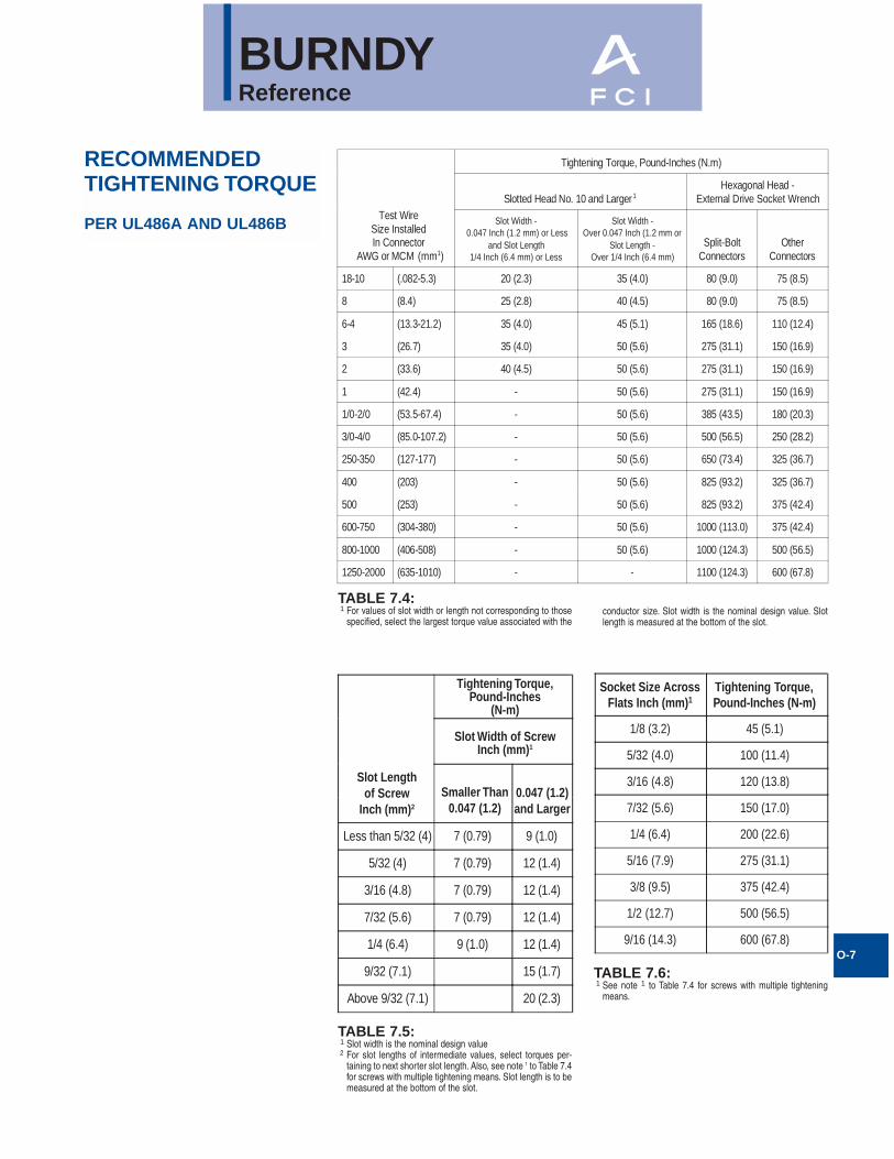
RECOMMENDEDTIGHTENING TORQUE
PER UL486A AND UL486B
O-7
Test WireSize InstalledIn Connector
AWG or MCM (mm1)
Tightening Torque, Pound-Inches (N.m)
Slotted Head No. 10 and Larger1Hexagonal Head -
External Drive Socket Wrench
Slot Width - 0.047 Inch (1.2 mm) or Less
and Slot Length1/4 Inch (6.4 mm) or Less
Slot Width -Over 0.047 Inch (1.2 mm or
Slot Length -Over 1/4 Inch (6.4 mm)
Split-BoltConnectors
OtherConnectors
18-10 (.082-5.3) 20 (2.3) 35 (4.0) 80 (9.0) 75 (8.5)
8 (8.4) 25 (2.8) 40 (4.5) 80 (9.0) 75 (8.5)
6-4 (13.3-21.2) 35 (4.0) 45 (5.1) 165 (18.6) 110 (12.4)
3 (26.7) 35 (4.0) 50 (5.6) 275 (31.1) 150 (16.9)
2 (33.6) 40 (4.5) 50 (5.6) 275 (31.1) 150 (16.9)
1 (42.4) - 50 (5.6) 275 (31.1) 150 (16.9)
1/0-2/0 (53.5-67.4) - 50 (5.6) 385 (43.5) 180 (20.3)
3/0-4/0 (85.0-107.2) - 50 (5.6) 500 (56.5) 250 (28.2)
250-350 (127-177) - 50 (5.6) 650 (73.4) 325 (36.7)
400 (203) - 50 (5.6) 825 (93.2) 325 (36.7)
500 (253) - 50 (5.6) 825 (93.2) 375 (42.4)
600-750 (304-380) - 50 (5.6) 1000 (113.0) 375 (42.4)
800-1000 (406-508) - 50 (5.6) 1000 (124.3) 500 (56.5)
1250-2000 (635-1010) - - 1100 (124.3) 600 (67.8)
TABLE 7.4:1 For values of slot width or length not corresponding to those
specified, select the largest torque value associated with the
Socket Size AcrossFlats Inch (mm)1
Tightening Torque,Pound-Inches (N-m)
1/8 (3.2) 45 (5.1)
5/32 (4.0) 100 (11.4)
3/16 (4.8) 120 (13.8)
7/32 (5.6) 150 (17.0)
1/4 (6.4) 200 (22.6)
5/16 (7.9) 275 (31.1)
3/8 (9.5) 375 (42.4)
1/2 (12.7) 500 (56.5)
9/16 (14.3) 600 (67.8)
Slot Lengthof Screw
Inch (mm)2
Smaller Than0.047 (1.2)
0.047 (1.2)and Larger
Tightening Torque,Pound-Inches
(N-m)
Slot Width of ScrewInch (mm)1
Less than 5/32 (4) 7 (0.79) 9 (1.0)
5/32 (4) 7 (0.79) 12 (1.4)
3/16 (4.8) 7 (0.79) 12 (1.4)
7/32 (5.6) 7 (0.79) 12 (1.4)
1/4 (6.4) 9 (1.0) 12 (1.4)
9/32 (7.1) 15 (1.7)
Above 9/32 (7.1) 20 (2.3)
TABLE 7.5:1 Slot width is the nominal design value2 For slot lengths of intermediate values, select torques per-
taining to next shorter slot length. Also, see note 1 to Table 7.4for screws with multiple tightening means. Slot length is to bemeasured at the bottom of the slot.
TABLE 7.6:1 See note 1 to Table 7.4 for screws with multiple tightening
means.
conductor size. Slot width is the nominal design value. Slotlength is measured at the bottom of the slot.
BURNDYReference
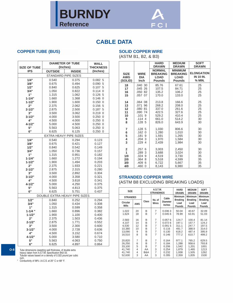
COPPER TUBE (BUS) SOLID COPPER WIRE(ASTM B1, B2, & B3)
STRANDED COPPER WIRE(ASTM B8 EXCLUDING BREAKING LOADS)
O-8
CABLE DATA
SIZE OF TUBEIPS
DIAMETER OF TUBE(Inches)
WALLTHICKNESS
(Inches)OUTSIDE INSIDESTANDARD PIPE SIZES
1/4"3/8"1/2"3/4"1"
1-1/4"1-1/2"
2"2-1/2"
3"3-1/2"
4"4-1/2"
5"6"
0.5400.6750.8401.0501.3151.6601.9002.3752.8753.5004.0004.5005.0005.5636.625
0.3750.4940.6250.8221.0621.3681.6002.0622.5003.0623.5004.0004.5005.0636.125
0.082 50.090 50.107 50.114 00.126 50.146 00.150 00.156 50.187 50.219 00.250 00.250 00.250 00.250 00.250 0
EXTRA HEAVY PIPE SIZES1/4"3/8"1/2"3/4"1"
1-1/4"1-1/2"
2"2-1/2"
3"3-1/2"
4"4-1/2"
5"6"
0.5400.6750.8401.0501.3151.6601.9002.3752.8753.5004.0004.5005.0005.5636.625
0.2940.4210.5420.7360.9511.2721.4941.9332.3152.8923.3583.8184.2504.8135.751
0.1230.1270.1490.1570.1820.1940.2030.2210.2800.3040.3210.3410.3750.3750.437
DOUBLE EXTRA HEAVY PIPE SIZES1/2"3/4"1"
1-1/4 "1-1/2"
2"2-1/2"
3"3-1/2"
4"4-1/2"
5"6"
0.8401.0501.3151.6601.9002.3752.8753.5004.0004.5005.0005.5636.625
0.2520.4340.5990.8961.1001.5031.7712.3002.7283.1523.5804.0634.897
0.2940.3080.3580.3820.4000.4360.5520.6000.6360.6740.7100.7500.864
SIZEAWG
(SOLID)
WIREDIAInch
HARDDRAWN
MEDIUMDRAWN
SOFTDRAWN
NORMALBREAKING
LOADPounds
MINIMUMELONGATION
IN 10 IN.% MIN.
BREAKINGLOAD
Pounds
18171615
141312111098
76543
21
1/02/03/04/0
.040 30
.045 26
.050 82
.057 07
.064 08
.071 96
.080 81
.090 74.101 9.114 4.128 5
.128 5
.162 0
.181 9
.204 3
.229 4
.257 6
.289 3
.324 9
.364 8
.409 6
.460 0
85.76107.5135.2170.0
213.8268.2337.0422.5529.2661.0826.0
1,0301,2801,5911,9702,439
3,0033,6884,5195,5186,7228,143
67.6184.71106.2133.0
166.6208.0261.6327.6410.4514.2643.9
806.61,0101,2651,5841,984
2,4503,0243,7304,5995,6676,980
25252525
25252525253030
3030303030
303035353535
SIZEA.S.T.M.
STRANDINGSHARD
DRAWNMEDIUMDRAWN
SOFTDRAWN
STRANDED
Class No. ofWires
CableDiameterInches
MimimumBreaking
LoadPounds
MimimumBreaking
LoadPounds
MimimumBreaking
LoadPounds
CircularMills
AWG
1,0221,624
2,5834,1076,53010,38013,09016,510
20,82026,25033,10041,74041,74052,630
2018
1614121098
765443
BB
BBBBBB
BBB
AAB&AAA
77
777777
777373
0.036 30.045 6
0.057 60.072 60.091 50.1160.1300.146
0.1640.1840.2060.2540.2320.285
50.0478.99
124.7197.1311.1491.7618.2777.2
977.11,2881,5421,8791,9382,359
40.6763.91
100.4157.7247.7388.9487.4610.7
765.2958.61,2011,4651,5051,835
32.0951.03
81.14124.2197.5314.0395.9499.2
629.5793.81001121312621530
Tube dimensions (exepting wall thickness, of double extraheavy) taken from A.S.T.M. Specification B42-33.Tubular values based on a density of 0.322 pound per cubicinch.
* Conductivity of 98% I.A.C.S. at 20° C or 68° F.
BURNDYReference
O-9
CABLE DATA (Continued)
250 Mcm.250 Mcm.250 Mcm.300 Mcm.300 Mcm.
300 Mcm.350 Mcm.350 Mcm.350 Mcm.400 Mcm.400 Mcm.
450 Mcm.450 Mcm.500 Mcm.500 Mcm.600 Mcm.600 Mcm.
700 Mcm.700 Mcm.750 Mcm.750 Mcm.800 Mcm.800 Mcm.
900 Mcm.900 Mcm.
1,000 Mcm.1,000 Mcm.1,250 Mcm.1,250 Mcm.
1,500 Mcm.1,500 Mcm.1,750 Mcm.1,750 Mcm.2,000 Mcm.2,000 Mcm.
AAAB
AAA
BAAAB
A&AAB
AAB&AAA
B&AA&AA
B
AAB&AAA
B&AAA
B&A
AAB&AAA
B&AAB
ABABAB
1219371219
371219371937
193719373761
376137613761
376137616191
61919112791127
0.6000.5740.5750.6570.628
0.6300.7100.6790.6810.7260.728
0.7700.7720.8110.8130.8910.893
0.9630.9640.9970.9981.0291.031
1.0921.0941.1511.1521.2881.289
1.4111.4121.5261.5261.6301.632
11,13011,36011,56013,17013,510
13,87015,14015,59016,06017,81018,320
19,75020,45021,95022,51027,02027,530
31,17031,82033,40034,09035,12036,360
39,51040,52043,83045,03055,67056,280
65,84067,54077,93078,80087,79090,050
8,7178,9868,952
10,39010,530
10,74012,04012,20012,45013,95014,140
15,59015,90017,32017,55021,06021,350
24,41024,74026,15026,51027,71028,270
31,17031,59034,40035,10043,59043,880
51,95052,65061,02061,43069,27070,210
72657265755987188718
90711017010170105801162011620
130801308014530145301744018140
203402034021790217902325023250
261502615029060290603632036320
435904359050850508505812058120
SIZEA.S.T.M.
STRANDINGSHARD
DRAWNMEDIUMDRAWN
SOFTDRAWN
Class No. ofWires
CableDiameterInches
MimimumBreaking
LoadPounds
MimimumBreaking
LoadPounds
MimimumBreaking
LoadPounds
CircularMills
COMPACT STRANDED COPPER CABLE(ASTM SPEC.B496)
CONDUCTOR SIZE NUMBEROF WIRES
CONDUCTORDIAMETER (IN.)KCMIL (OR) AWG
1000900800750700650600550
611
611
611
611
611
611
611
611
1.0600.9990.9380.9080.8770.8450.8130.775
500450400350300250
372
372
372
372
372
372
0.7360.7000.6590.6160.5700.520
4/03/02/01/01
193C
193C
193C
193C
193C
0.4750.4230.3760.3360.299
2468
7777
0.2680.2130.1690.134
STRANDED COPPER WIRE (Continued)(ASTM B8 EXCLUDING BREAKING LOADS)
52,63066,37066,37083,69083,69083,690
105,500105,500105,500133,100133,100133,100
167,800167,800167,800211,600211,600211,600
322111
1/01/01/02/02/02/0
3/03/03/04/04/04/0
B&AAA
B&AAAAB
A&A—B
A&A—B
A&A—B
A&A—B
7373719
7121971219
7121971219
0.2600.3200.2920.3600.3280.332
0.3680.3900.3730.4140.4380.419
0.4640.4920.4700.5220.5220.528
2,4332,9133,0453,6213,8043,899
4,7524,8414,9015,9266,0486,152
7,3667,5567,6989,1549,4839,617
1,8852,2992,3612,8792,9583,037
3,7053,7553,8054,6404,7034,765
5,8125,8905,9707,2787,3787,479
159219292007243224322531
306731913191386738674024
487648765074614961496149
SIZEA.S.T.M.
STRANDINGSHARD
DRAWNMEDIUMDRAWN
SOFTDRAWN
STRANDED
Class No. ofWires
CableDiameterInches
MimimumBreaking
LoadPounds
MimimumBreaking
LoadPounds
MimimumBreaking
LoadPounds
CircularMills
AWG
1 58 Wires Minimum2 35 Wires Minimum3 18 Wires MInimum
BURNDYReference
O-10
CABLE DATA (Continued)
CONDUCTOR SIZEKCMIL OR B &SG
(AWG)
STRANDING ANDDIAMETER
NOMINALDIAMETER
CLASS
88888
41/.020149/.0184133/.0111168/.010420/.0063
.156
.166
.167
.157
.162
IGHKM
77777
49/.020652/.0201133/.0125210/.010532/.0063
.185
.185
.188
.179
.196
GIHKM
66666
49/.023163/.0201133/.0140266/.010665/.0063
.208
.207
.210
.210
.215
GIHKM
55555
49/.026084/.0201133/.0158336/.010836/.0063
.234
.235
.237
.235
.240
GIHKM
44444
49/.0292105/.0201133/.0177420/.010
1064/.0063
.263
.263
.266
.272
.269
GIHKM
33333
49/.0328133/.0199133/.0201532/.010
1323/.0063
.295
.299
.291
.304
.305
GHIKM
22222
49/.0368133/.0223161/.0201665/.010
1666/.0063
.331
.335
.319
.338
.337
GHIKM
11111
133/.0251210/.0201259/.018836/.010
2107/.0063
.377
.367
.378
.397
.376
GIHKM
1/01/01/01/01/0
133/.0282259/.0202266/.02011064/.010
2646/.0063
.423
.424
.441
.451
.423
GHIKM
2/02/02/02/02/0
133/.0316259/.0227342/.02011323/.010
3325/.0063
.474
.477
.500
.470
.508
GHIKM
3/03/03/03/03/0
133/.0355259/.0255418/.02011666/.010
4256/.0063
.533
.536
.549
.533
.576
GHIKM
4/04/04/04/04/0
133/.0399259/.0286532/.02012107/.010
5320/.0063
.599
.601
.613
.627
.645
GHIKM
250250250250250
259/.0311427/.0242637/.02012499/.010
6384/.0063
.650
.653
.682
.682
.713
GHIKM
300300300300300
259/.0340427/.0265735/.02012989/.010
7581/.0063
.714
.716
.737
.768
.768
GHIKM
350350350350350
259/.0368427/.0286882/.02013458/.010
8806/.0063
.773
.772
.800
.809
.825
GHIKM
400400400400400
259/.0393427/.0306980/.02013990/.010
10101/.0063
.825
.826
.831
.878
.901
GHIKM
450450450450450
259/.0417427/.0325
1127/.02014522/.010
11396/.0063
.876
.878
.894
.933
.940
GHIKM
500500500500500
259/.0439427/.0342
1225/.02015054/.010
12691/.0063
.922
.923
.941
.988
.997
GHIKM
600600600600600
427/.0375703/.0292
1470/.02015985/.010
14945/.0063
1.0131.0221.0271.1251.084
GHIKM
700700700700700
427/.0405703/.0316
1729/.02016916/.010
17507/.0063
1.0941.1061.1941.2071.183
GHIKM
800800800800800
427/.0433703/.0337
1995/.02017980/.010
20069/.0063
1.1691.1801.2901.3051.256
GHIKM
900900900900900
427/.0459703/.0358
2261/.02019065/.010
22631/.0063
1.2391.2531.3721.3231.331
GHIKM
10001000100010001000
427/.0484703/.0377
2527/.020110101/.01025193/.0063
1.3071.3201.4271.4191.404
GHIKM
CONDUCTOR SIZEKCMIL OR B &SG
(AWG)
STRANDING ANDDIAMETER
NOMINALDIAMETER
CLASS
FLEXIBLE COPPER STRANDED CABLE
BURNDYReference
O-11
CABLE DATA (Continued)
SIZE OFTUBE IPS
DIAMETER OF TUBE (IN.) WALLTHICKNESSOUTSIDE INSIDE
STANDARD PIPE SIZES1/43/81/23/41
1-1/41-1/2
22-1/2
33-1/2
44-1/2
56
0.5400.6750.8401.0501.3151.6601.9002.3752.8753.5004.0004.5005.0005.5636.625
0.3640.4930.6220.8241.0491.3801.6102.0672.4693.0683.5484.0264.5065.0476.065
0.0880.0910.1090.1130.1330.1400.1450.1540.2030.2160.2260.2370.2470.2580.280
EXTRA HEAVY PIPE SIZES1/43/81/23/41
1-1/41-1/2
22-1/2
33-1/2
44-1/2
56
0.5400.6750.8401.0501.3151.6601.9002.3752.8753.5004.0004.5005.0005.5636.625
0.3020.4230.5460.7420.9571.2781.5001.9392.3232.9003.3643.8264.2904.8135.761
0.1190.1260.1470.1540.1790.1910.2000.2180.2760.3000.3180.3370.3550.3750.432
CABLECODEWORD
SIZECircularmils orA.W.G.
COPPEREQUIVALENT
based onequal D.C.resistance,
Cu. 97%Alum. 61%
NO. OFWIRES
CABLE ULTIMATESTRENGTH
PoundsDIA.
Inches
MistletoeOrchidVioletNasturtium
ArbutusLilacAnemoneCrocus
MagnoliaGoldenrodBluebellLarkspur
MarigoldNarcissusCarnationCoreopsis
Dogwood
556500636000715500715500
795000795000874500874500
95400095400010335001033500
1113000127200014310001590000
1590000
350000400000450000450000
500000500000550000550000
600000600000650000650000
700000800000900000
1000000
100000
37373761
37613761
37613761
61616161
91
0.8580.9180.9740.975
1.0261.0281.0771.078
1.1241.1261.1701.172
1.2161.3001.3791.454
1.454
9830112401264013150
13770143301483015760
16180168601753018260
19660220002430027000
28100
ALUMINUM TUBE ALUMINUM 1350 CABLEBARE-CLASS B
ALUMINUM 1350 CABLEBARE-CLASSES AA AND AHARD DRAWN
SIZE
CircularMils orA.W.G.
STRANDING
No. ofWires
UltimateStrength
PoundsHard
Drawn
MinimumUltimateStrength
Pounds3/4 Hard
MinimumUltimateStrength
PoundsInter
Temper
CableDIA.
Inches
CopperEquivelentbased uponequal D.C.resistance,
Co. 97%Alum 51%
250000300000350000
400000450000500000550000
600000650000700000750000
800000900000
10000001100000
1200000125000013000001400000
1500000160000017000001750000
1800000190000020000002500000
30000003500000
157300188800220200
251500283000314500346000
377000409000440000472000
503000566000629000692000
755000786000818000880000
943000100600010690001101000
1132000119500012580001570000
18900002200000
373737
37373761
61616161
61616191
91919191
91127127127
127127127127
169169
0.5750.6290.681
0.7280.7720.8130.855
0.8930.9290.9640.998
1.0311.0941.1521.209
1.2631.2891.3151.364
1.4121.4591.5041.526
1.5481.5901.6321.824
1.9982.158
486058316680
735281109012
10490
11450119401286013510
14410159001767020210
21630225302343024750
26500288403063031530
32450335703534043300
5301060610
333840054673
5341600766757344
801086789346
10010
10680120101335014680
16020166901735018700
20020213602269023350
24030253602670033380
4005046730
294635344123
4713530158906480
7068765782478835
9424106001178012950
14130147201531016500
17670188502002020610
21210223802356029460
3534041230
CABLECODEWORD
SIZECircularmils orA.W.G.
COPPEREQUIVALENT
based onequal D.C.resistance,
Cu. 97%Alum. 61%
NO. OFWIRES
CABLEDIA.
Inches
PeachbellRoseLilyIris
PansyPoppyAsterPhlox
OxlipDaisyLaurelTulip
CannaCosmosSyringaDahlia
6432
11/02/03/0
4/0266800266800336400
397500477000477000556500
8654
321
1/0
2/03/03/04/0
250000300000300000350000
7777
7777
771919
19193719
0.1840.2320.2600.292
0.3280.3680.4140.464
0.5220.5860.5930.666
0.7240.7930.7950.856
52882610221266
1537186523502845
3590452548005940
6880809086009440
ULTIMATESTRENGTH
Pounds
BURNDYReference
O-12
CABLE DATA (Continued)
ASCR DIAMETERInches
CODEWORD
Cir.Mils. orA.W.G.
STRANDINGNumber
of Strands
TurkeyThrushSwanSwanate
SwallowSparrowSparateRobin
RavenQuailPigeonPenquin
WaxwingOwlPartridgeOstrich
MerlinLinnetOrioleChickadeeBrantIbisLarkPelicanFlickerHawk
6544
3221
1/02/03/04/0
266800266800266800300000
336400336400336400397500397500397500397500477000477000477000
6667
6676
6666
18262626
18263018242630182426
1111
1111
1111
1777
1771777177
0.1980.2230.2500.257
0.2810.3160.3250.355
0.3980.4470.5020.563
0.6090.6330.6420.680
0.6840.7210.7410.7430.7710.7830.8060.8140.8460.858
0.06610.07430.08340.1029
0.09370.10520.12990.1182
0.13270.14900.16720.1878
0.12170.21090.23640.2505
0.13670.26550.31770.14860.25750.28830.34530.16280.28200.3162
8766
5443
21
1/02/0
3/03/03/0
188700
4/04/04/0
250000250000250000250000300000300000300000
1170146018302288
2250279035253480
4280534566758420
71009645
1125012650
8950140501704010400146901619019980123001720019430
Alum. Steel
Completecable
CopperEquivalent
basedupon equal
D.C.resistanceCu. 97%
Alum. 61%
UltimateStrengthPounds
SteelCore
ACSR
HIGH STRENGTH ACSR
ASCR DIAMETERInches
CODEWORD
477000556500556500556500
605000605000605000636000
636000636000666600715500
715500715500795000795000
795000874500900000954000
10335001113000127200014310001590000
30242630
24263024
26302454
26305426
30545454
5454545454
7777
77197
71977
71977
19777
719191919
0.8830.9140.9270.953
0.9530.9660.9940.977
0.9901.0191.0001.036
1.0511.0811.0931.108
1.1401.1461.1621.196
1.2461.2931.3821.4651.545
0.37830.30450.3410.409
0.3180.3560.4260.326
0.3650.4370.3330.345
0.3870.4630.3640.408
0.4890.3820.3870.399
0.4150.4310.4610.4890.515
300000350000350000350000
380500380500380500400000
400000400000419000450000
450000450000500000500000
500000550000566000600000
6500007000008000009000001000000
23300198502240027200
21500241003000022600
25000315002370026300
28100346002850031200
38400314003230034200
3710040200448005040056000
Cir.Mils. orA.W.G.
STRANDINGNumber
of Strands
Alum. SteelComplete
cable
CopperEquivalent
basedupon equal
D.C.resistanceCu. 97%
Alum. 61%
UltimateStrengthPounds
SteelCore
HenParakeetDoveEagle
PeacockSquabTealRook
GrosbeakEgretFlamingoCrow
StarlingRedwingCondorDrake
MallardCraneCanaryCardinal
CurlewFinchPheasantPloverFalcon
ASCR DIAMETERInches
CODEWORD
GrousePetrelMinorcaLeghorn
GuineaDotterelDorkingCochinBrahma
80000101800110800134600
159000176900190800211300203200
8121212
1212121216
1777
77779
0.3670.4610.4810.530
0.5760.6070.6310.6630.714
0.16700.27630.28830.3177
0.34530.36420.37830.39810.4885
50310641606970084600
100000111200120000132900127800
52009860
1073012920
1520016440177301964027500
Cir.Mils. orA.W.G.
STRANDINGNumber
of Strands
Alum. Steel
Completecable
CopperEquivalent
basedupon equal
D.C.resistanceCu. 97%
Alum. 61%
UltimateStrengthPoundsSteel
Core
BURNDYReference
O-13
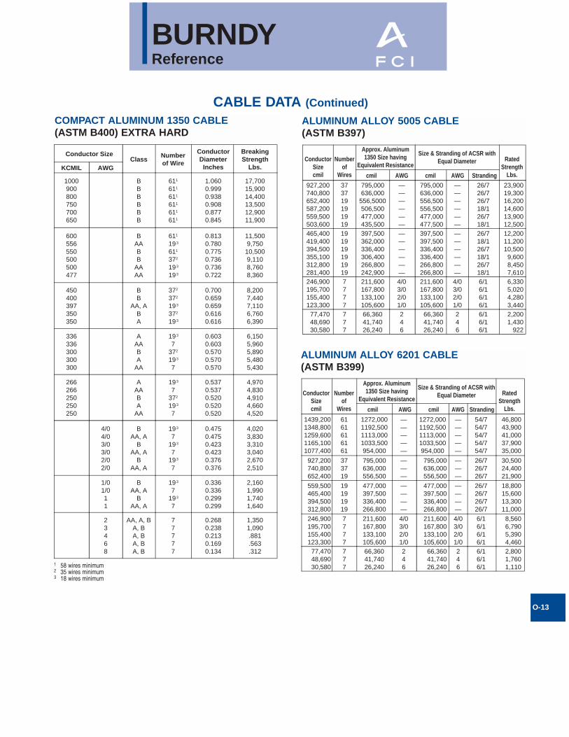
CABLE DATA (Continued)
Conductor SizeClass
Numberof Wire
ConductorDiameter
Inches
BreakingStrength
Lbs.KCMIL AWG
1000900800750700650
BBBBBB
611
611
611
611
611
611
1.0600.9990.9380.9080.8770.845
17,70015,90014,40013,50012,90011,900
600556550500500477
BAABB
AAAA
611
193
611
372
193
193
0.8130.7800.7750.7360.7360.722
11,5009,75010,5009,1108,7608,360
450400397350350
BB
AA, ABA
372
372
193
372
193
0.7000.6590.6590.6160.616
8,2007,4407,1106,7606,390
336336300300300
AAABA
AA
193
7372
193
7
0.6030.6030.5700.5700.570
6,1505,9605,8905,4805,430
266266250250250
AAABA
AA
193
7372
193
7
0.5370.5370.5200.5200.520
4,9704,8304,9104,6604,520
4/04/03/03/02/02/0
BAA, A
BAA, A
BAA, A
193
7193
7193
7
0.4750.4750.4230.4230.3760.376
4,0203,8303,3103,0402,6702,510
1/01/011
BAA, A
BAA, A
193
7193
7
0.3360.3360.2990.299
2,1601,9901,7401,640
23468
AA, A, BA, BA, BA, BA, B
77777
0.2680.2380.2130.1690.134
1,3501,090.881.563.312
COMPACT ALUMINUM 1350 CABLE(ASTM B400) EXTRA HARD
ALUMINUM ALLOY 5005 CABLE(ASTM B397)
373719191919
795,000636,000
556,5000506,500477,000435,500
——————
795,000636,000556,500556,500477,000477,500
——————
26/726/726/718/126/718/1
23,90019,30016,20014,60013,90012,500
191919191919
397,500362,000336,400306,400266,800242,900
——————
397,500397,500336,400336,400266,800266,800
——————
26/718/126/718/126/718/1
12,20011,20010,5009,6008,4507,610
7777
211,600167,800133,100105,600
4/03/02/01/0
211,600167,800133,100105,600
4/03/02/01/0
6/16/16/16/1
6,3305,0204,2803,440
927,200740,800652,400587,200559,500503,600465,400419,400394,500355,100312,800281,400246,900195,700155,400123,300
77,47048,69030,580
777
66,36041,74026,240
246
66,36041,74026,240
246
6/16/16/1
2,2001,430
922
ConductorSizecmil
Numberof
Wires
RatedStrength
Lbs.
Approx. Aluminum1350 Size having
Equivalent Resistance
Size & Stranding of ACSR withEqual Diameter
cmil AWG cmil StrandingAWG
ALUMINUM ALLOY 6201 CABLE(ASTM B399)
1439,2001348,8001259,6001165,1001077,400
6161616161
1272,0001192,5001113,0001033,500954,000
—————
1272,0001192,5001113,0001033,500954,000
—————
54/754/754/754/754/7
46,80043,90041,00037,90035,000
927,200740,800652,400
373719
795,000636,000556,500
———
795,000636,000556,500
———
26/726/726/7
30,50024,40021,900
559,500465,400394,500312,800
19191919
477,000397,500336,400266,800
————
477,000397,500336,400266,800
————
26/726/726/726/7
18,80015,60013,30011,000
246,900195,700155,400123,300
7777
211,600167,800133,100105,600
4/03/02/01/0
211,600167,800133,100105,600
4/03/02/01/0
6/16/16/16/1
8,5606,7905,3904,460
77,47048,69030,580
777
66,36041,74026,240
246
66,36041,74026,240
246
6/16/16/1
2,8001,7601,110
ConductorSizecmil
Numberof
Wires
RatedStrength
Lbs.
Approx. Aluminum1350 Size having
Equivalent Resistance
Size & Stranding of ACSR withEqual Diameter
cmil AWG cmil StrandingAWG
1 58 wires minimum2 35 wires minimum3 18 wires minimum
BURNDYReference
O-14
CABLE DATA (Continued)
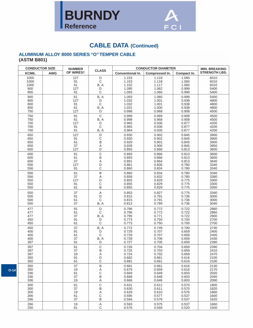
CONDUCTOR SIZE NUMBEROF WIRES† CLASS
CONDUCTOR DIAMETER MIN. BREAKINGSTRENGTH LBS.KCMIL AWG Conventional In. Compressed In. Compact In.
100010001000900900
127916112791
DC
B, ADC
1.1531.1531.1521.0951.093
1.1191.1181.1171.0621.060
1.0601.0601.0600.9990.999
60106010601054005400
900800800800750
611279161127
B, ADC
B, AD
1.0931.0321.0321.0310.998
1.0601.0011.0011.0000.968
0.9990.9380.9380.9380.908
54004800480048004500
750750700700700
91611279161
CB, A
DC
B, A
0.9990.9980.9650.9650.964
0.9690.9680.9360.9360.935
0.9080.9080.8770.8770.877
45004500420042004200
650650650650600
127916137127
DCBAD
0.9300.9300.9290.9280.893
0.9020.9020.9010.9000.866
0.8450.8450.8450.8450.813
39003900390039503600
600600600556556
91613712791
CBADC
0.8930.8930.8910.8610.860
0.8660.8660.8640.8350.834
0.8130.8130.8130.7800.780
36003600364033403340
556556550550550
61371279161
BADCB
0.8600.8580.8550.8550.855
0.8340.8320.8290.8290.829
0.7800.7800.7750.7750.775
33403380330033003300
550500500500
37916137
ADC
B, A
0.8530.8150.8150.813
0.8270.7910.7910.789
0.7750.7360.7360.736
3340300030003040
477477477450450
9161379161
DC
B, ADC
0.7960.7960.7950.7730.773
0.7720.7720.7710.7500.750
0.7220.7220.7220.7000.700
28602860290027002700
450400400400397
3791613791
B, ADC
B, AD
0.7720.7290.7290.7280.727
0.7490.7070.7070.7060.705
0.7000.6590.6590.6590.659
27302400240024302390
397397397350350
6137199161
CBADC
0.7260.7250.7240.6820.681
0.7040.7030.7020.6610.661
0.6590.6590.6590.6160.616
23902410247021002100
350350336336336
3719613719
BACBA
0.6810.6790.6690.6680.666
0.6610.6590.6490.6480.646
0.6160.6160.6030.6030.603
21302170202020402090
300300300266266
6137196137
CBACB
0.6310.6300.6290.5950.594
0.6120.6110.6100.5770.576
0.5700.5700.5760.5370.537
18001820186016001620
266250
1961
AC
0.5930.576
0.5750.559
0.5370.520
16601500
ALUMINUM ALLOY 8000 SERIES “O”TEMPER CABLE(ASTM B801)
BURNDYReference
O-15
CABLE DATA (Continued)
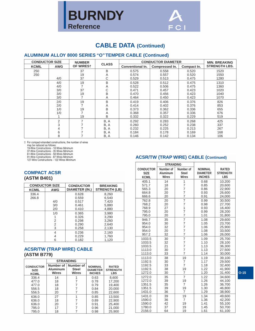
CONDUCTOR SIZE NUMBEROF WIRES† CLASS
CONDUCTOR DIAMETER MIN. BREAKINGSTRENGTH LBS.KCMIL AWG Conventional In. Compressed In. Compact In.
250250
4/0
371937
BAC
0.5750.5740.529
0.5580.5570.513
0.5200.5200.475
152015501280
4/04/03/03/03/0
197
37197
BACBA
0.5280.5220.4710.4700.464
0.5120.5060.4570.4560.450
0.4750.4750.4230.4230.423
13101360102010401070
2/02/01/01/01
197
197
19
BABAB
0.4190.4140.3730.3680.332
0.4060.4020.3620.3570.322
0.3760.3760.3360.3360.229
826853655676519
23468
77777
B, AB, AB, AB, AB, A
0.2920.2600.2320.1840.146
0.2830.2520.2250.1780.142
0.2680.2380.2130.1690.134
425337267168106
ALUMINUM ALLOY 8000 SERIES “O”TEMPER CABLE (Continued)
ACSR/TW (TRAP WIRE) CABLE (Continued)
STRANDINGNOMINALCONDUCTOR
SIZEKCMIL
DIAMETERINCHES
RATEDSTRENGTH
LBSAluminum
Wires
Number ofNumber ofSteelWires
405.1571.7565.3664.8666.6
1418202020
17777
0.680.850.860.930.91
10,20020,60022,90026,60024,000
762.8768.2768.9795.0795.0
2020272020
77177
0.990.980.930.991.01
30,50027,70016,40028,20031,800
946.7954.0954.0954.0957.2
3530322032
77777
1.081.051.061.081.06
29,60023,70025,90033,50026,000
1033.51033.51033.51113.01113.0
3032213033
77777
1.091.101.131.131.14
25,70028,10036,30027,50030,000
1113.01192.51192.51192.51272.0
3830333830
1977197
1.191.171.181.221.20
39,10029,50032,40041,90031,400
1272.01272.01351.51351.51431.0
3539353936
7197197
1.221.261.261.301.29
34,60044,10036,70046,80038,900
1431.01590.01590.01780.02156.0
3936423764
197191919
1.341.361.411.451.61
49,60042,20055,10050,70061,100
COMPACT ACSR(ASTM B401)
CONDUCTOR SIZE CONDUCTORDIAMETER (IN.)
BREAKINGSTRENGTH (LB)KCMIL AWG
336.4266.8
4/03/02/0
0.6280.5590.5170.4610.410
8,2606,5407,4205,8804,880
1/01223
0.3650.3260.2980.2900.258
3,9803,2903,2602,6402,130
446
0.2360.2290.182
2,1601,7601,120
ACSR/TW (TRAP WIRE) CABLE(ASTM B779)
STRANDING
NOMINALCONDUCTORSIZE
KCMILDIAMETER
INCHES
RATEDSTRENGTH
LBS
Number ofAluminum
Wires
Number ofSteelWires
336.4477.0477.0556.5556.5
1418181820
17777
0.630.780.790.840.85
8,60017,20019,40020,00022,600
636.0636.0636.0795.0795.0
2718201718
17777
0.850.890.910.960.98
13,50022,90025,40021,00025,900
† For compact-stranded constructions, the number of wiresmay be reduced as follows:19-Wire Constructions - 18 Wires Minimum37-Wire Constructions - 35 Wires Minimum61-Wire Constructions - 58 Wires Minimum91-Wire Constructions - 87 Wires Minimum127-Wire Constructions - 122 Wires Minimum
BURNDYReference
O-16
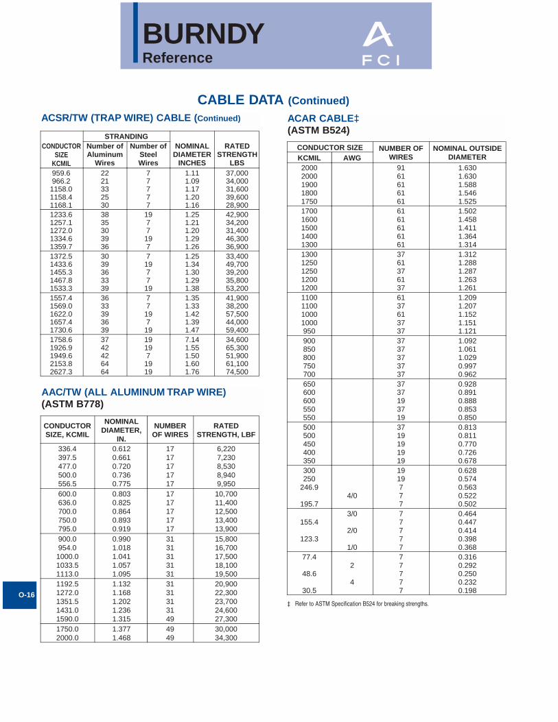
CABLE DATA (Continued)
STRANDINGNOMINAL
DIAMETERINCHES
RATEDSTRENGTH
LBS
Number ofAluminum
Wires
Number ofCONDUCTORSIZE
KCMILSteelWires
959.6966.2
1158.01158.41168.1
2221332530
77777
1.111.091.171.201.16
37,00034,00031,60039,60028,900
1233.61257.11272.01334.61359.7
3835303936
1977197
1.251.211.201.291.26
42,90034,20031,40046,30036,900
1372.51433.61455.31467.81533.3
3039363339
7197719
1.251.341.301.291.38
33,40049,70039,20035,80053,200
1557.41569.01622.01657.41730.6
3633393639
7719719
1.351.331.421.391.47
41,90038,20057,50044,00059,400
1758.61926.91949.62153.82627.3
3742426464
191971919
7.141.551.501.601.76
34,60065,30051,90061,10074,500
ACSR/TW (TRAP WIRE) CABLE (Continued)
CONDUCTOR SIZE NUMBER OFWIRES
NOMINAL OUTSIDEDIAMETERKCMIL AWG
20002000190018001750
9161616161
1.6301.6301.5881.5461.525
17001600150014001300
6161616161
1.5021.4581.4111.3641.314
13001250125012001200
3761376137
1.3121.2881.2871.2631.261
1100110010001000950
6137613737
1.2091.2071.1521.1511.121
900850800750700
3737373737
1.0921.0611.0290.9970.962
650600600550550
3737193719
0.9280.8910.8880.8530.850
500500450400350
3719191919
0.8130.8110.7700.7260.678
300250
246.9
195.74/0
1919777
0.6280.5740.5630.5220.502
155.4
123.3
3/0
2/0
1/0
77777
0.4640.4470.4140.3980.368
77.4
48.6
30.5
2
4
77777
0.3160.2920.2500.2320.198
AAC/TW (ALL ALUMINUM TRAP WIRE)(ASTM B778)
ACAR CABLE‡(ASTM B524)
CONDUCTORSIZE, KCMIL
NOMINALDIAMETER,
IN.
NUMBEROF WIRES
RATEDSTRENGTH, LBF
336.4397.5477.0500.0556.5
0.6120.6610.7200.7360.775
1717171717
6,2207,2308,5308,9409,950
600.0636.0700.0750.0795.0
0.8030.8250.8640.8930.919
1717171717
10,70011,40012,50013,40013,900
900.0954.01000.01033.51113.0
0.9901.0181.0411.0571.095
3131313131
15,80016,70017,50018,10019,500
1192.51272.01351.51431.01590.0
1.1321.1681.2021.2361.315
3131313149
20,90022,30023,70024,60027,300
1750.02000.0
1.3771.468
4949
30,00034,300
‡ Refer to ASTM Specification B524 for breaking strengths.
BURNDYReference
O-17
CABLE DATA (Continued)
266.8266.8266.8266.8
22242630
7777
.622
.633
.642
.660
603074108880
11700300.0 26 7 .680 9970336.4336.4336.4336.4336.4
2022242630
77777
.692
.701
.710
.720
.741
599076109340
1120014800
397.5397.5397.5397.5397.5
2022242630
77777
.752
.762
.772
.783
.806
70908990
110001300017500
477.0477.0477.0477.0477.0
2022242630
77777
.823
.834
.846
.858
.883
849010800130001560021000
500.0 30 7 .904 22000556.5556.5556.5556.5556.5
2022242630
77777
.890
.901
.914
.927
.953
991012600152001820024500
605.0605.0605.0605.0
24263030
777
19
.953
.966
.994
.994
16500197002600026600
636.0636.0636.0636.0636.0636.0
202224263030
77777
19
.951
.963
.977
.9901.0191.019
113001410017300207002740028000
666.6666.6
2426
77
1.0001.104
1820021700
715.5715.5715.5
242630
77
19
1.0361.0511.081
195002330030800
795.0795.0795.0795.0795.0795.0795.0795.0
4220452224542630
7777777
19
1.0551.0631.0631.0771.0921.0921.1081.140
1180014200142001770021700217002590034300
900.0900.0
4554
77
1.1311.162
1580024600
954.0954.0954.0954.0954.0954.0954.0
42204548245430
777777
19
1.1551.1851.1651.1751.1961.1961.248
14200167001670019700260002600041100
SIZE AWGOR KCMIL
STRANDING CONDUCTORDIAMETER
RATEDSTRENGTH
POUNDSALUMINUM STEEL
SSAC CABLE SSAC CABLE (Continued)
SIZE AWGOR KCMIL
STRANDING CONDUCTORDIAMETER
RATEDSTRENGTH
POUNDSALUMINUM STEEL1033.51033.51033.51033.5
42454854
7777
1.2031.2121.2221.245
15400181002130028200
1113.01113.01113.01113.0
42454854
77719
1.2481.2591.2691.293
16300195002300030400
1192.51192.51192.51192.5
42454854
77719
1.2921.3021.3131.338
17500209002460032600
1272.01272.01272.01272.0
42454854
77719
1.3341.3451.3571.382
18700223002620034100
1351.51351.51351.51351.5
42454854
77719
1.3761.3861.3981.424
19900237002790036200
1431.01431.01431.01431.0
42454854
77719
1.4151.4271.4391.465
21000251002950038400
1510.51510.5
4554
719
1.4661.505
2650040500
1590.01590.01590.01590.0
42454854
77719
1.4921.5041.5171.545
23400279003220042600
1780.0 84 19 1.602 354001869.0 68 7 1.603 215002034.5 72 7 1.681 27200
BURNDYReference
O-18
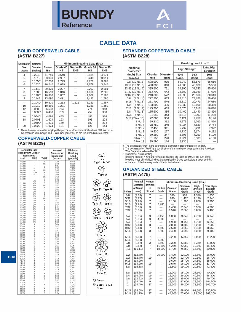
CABLE DATASOLID COPPERWELD CABLE(ASTM B227)
ConductorSize
(AWG)
NominalDiameter(Inches)
CircularMils
Minimum Breaking Load (lbs.)Grade 40
HSGrade 40
EHSGrade 30
HSGrade 30
EHS
45—6
41,74033,09027,23026,240
3,5402,9372,7792,679
————
3,9343,2492,7792,679
4,6713,9113,3673,246
78—9
20,82016,51016,38013,090
2,2071,8161,8021,491
————
2,2071,8161,8021,491
2,6812,2052,1881,790
—1012—
10,82010,3806,5306,400
1,2831,231774759
1,325———
1,2831,231774759
1,4871,460918900
—18—20
0.20430.18190.1650*0.1620
0.14430.12850.1280*0.1144
0.1040*0.10190.08080.0800*
0.0640*0.04030.0390*0.0320
4,0961,6241,5211,024
485193180121
————
485193180121
576228214144
STRANDED COPPERWELD CABLE(ASTM B228)
NominalDiameter†(Inch) Size
A.W.G.‡Circular
MilsDiameter*
(Inch)
Breaking Load Lbs.**
High StrengthExtra HighStrength
40%Cond.
30%Cond.
30%Cond.
7/8 (19 No. 5)13/16 (19 No. 6)23/32 (19 No. 7)27/32 (19 No. 8)9/16 (19 No. 9)5/8 (7 No. 4)9/16 (7 No. 5)1/2 (7 No. 6)7/16 (7 No. 7)3/8 (7 No. 8)
11/32 (7 No. 9)5/16 (7 No. 10)
3 No. 53 No. 63 No. 73 No. 83 No. 9
3 No. 103 No. 12
628,900498,800395,500313,700248,800292,200231,700183,800145,700115,60091,65072,68099,31078,75062,45049,53039,28031,15019,590
.910
.810
.721
.642
.572
.613
.546
.486
.433
.385
.343
.306
.392
.349
.311
.277
.247
.220
.174
50,24041,60034,39028,38023,39022,31018,51015,33012,67010,4608,6167,1218,3736,9345,7324,7303,8983,2212,236
55,57045,83037,74031,04025,50024,78020,47016,89013,91011,4409,3937,7589,2627,6396,2915,1744,2503,509
—
66,91055,53045,85037,69030,61029,43024,65020,46016,89013,89011,2809,196
11,8609,7547,9226,2825,1294,160
—
GALVANIZED STEEL CABLE(ASTM A475)
Minimum Breaking Load (lbs.)
Inches
NominalDiameterof Strand
(mm)
Numberof Wires
inStrand
UtilitiesGrade
CommonGrade
Siemens-MartinGrade
High-Strength
Grade
Extra High-Strength
Grade1/85/323/163/167/327/32
1/41/41/49/329/325/16
5/165/163/83/87/16
1/21/29/169/165/8
5/83/47/811
1-1/81-1/4
(3.18)(3.97)(4.76)(4.76)(5.56)(5.56)
(6.35)(6.35)(6.35)(7.14)(7.14)(7.94)
(7.94)(7.94)(9.52)(9.52)(11.11)
(12.70)(12.70)(14.29)(14.29)(15.88)
(15.88)(19.05)(22.22)(25.40)(25.40)
(28.58)(31.75)
777737
337373
77377
7197197
191919937
3737
———
2,400——
3,1504,500
——
4,6006,500
—6,0008,50011,50018,000
25,000————
—————
——
540870
1,150—
1,4001,540
1,860—
1,9002,0802,5702,490
3,200—
3,3304,2505,700
7,4007,6209,6009,64011,600
11,00016,00021,90028,70028,300
36,00044,600
9101,4701,900
—2,3402,560
3,040—
3,1503,3804,2504,090
5,350—
5,5606,9509,350
12,10012,70015,70016,10019,100
18,10026,20035,90047,00046,200
58,90073,000
1,3302,1402,850
—3,5003,850
4,730—
4,7505,2606,4006,350
8,000—
8,36010,80014,500
18,80019,10024,50024,10029,600
28,10040,80055,80073,20071,900
91,600113,600
1,8302,9403,990
—4,9005,400
6,740—
6,6507,5008,9509,100
11,200—
11,80015,40020,800
26,90026,70035,00033,70042,400
40,20058,30079,700104,500102,700
130,800162,200
COPPERWELD-COPPER CABLE(ASTM B229)
Conductor SizeHard Drawn Copper
EquivalentTYPE
NominalDiameter ofConductor
(inches)
MinimumBreaking
Load(pounds)cmil AWG
350,000350,000350,000300,000300,000300,000250,000250,000250,000
211,600211,600211,600211,600167,800167,800167,800167,800167,800167,800133,100133,100133,100133,100133,100105,600105,600105,600105,60083,69083,69083,69083,69083,69066,36066,36066,36066,36066,36066,36066,36055,62052,62052,62052,62052,62041,74041,74041,74041,74033,09033,09033,09026,24026,24026,24020,82020,82016,51016,51016,51011,750
—————
211,600———4/04/04/04/04/03/03/03/03/03/03/02/02/02/02/02/01/01/01/01/0111112222222333334444555666778889
EEKVE
EKVE
EKVEGEKVFEJGEKVFKJGVFKJGFNKJGFPNKJAGFPNKJAPNDAPDADACDADACD
0.7880.7350.7540.7290.6800.6980.6660.6210.6370.6130.5830.5710.5860.5500.5450.5550.5190.5090.5220.4900.5340.4940.4630.4650.4360.4750.4400.4120.3880.4640.4230.3920.3670.3460.4620.4130.3770.3490.3660.3270.3080.4110.3680.3360.3110.3260.3660.3280.3480.2900.3260.3100.2580.2760.2300.2250.2460.2230.2190.1990.1790.174
32,42023,85023,48027,77020,96020,73023,92017,84017,42020,73015,64015,37015,00012,29016,80016,17012,86012,37012,2009,980
17,60013,43010,5109,8468,094
14,49010,9708,5636,536
15,41011,9009,0006,9565,266
16,87012,6809,7307,3225,8765,6264,233
13,91010,3907,9105,9554,810
11,4208,4607,3403,9389,3116,0353,1934,9422,5852,1434,0222,7543,2562,2331,3621,743
* These diameters are often employed by purchasers for communication lines BUT are not inthe American Wire Gauge (B & S Wire Gauge) series, as are the other diameters listed.
† The designation "Inch" is the approximate diameter in proper fraction of an inch.‡ The designation of "AWG" is a combination of the number of wires each of the American
Wire Gage size indicated by "No."* Diameter of circumscribing.** Breaking loads of 7-wire and 19-wire conductors are taken as 90% of the sum of the
breaking loads of individual wires; breaking load of 3-wire conductors is taken as 95% of the sum of the breaking loads of the individual wires.
BURNDYReference
O-19
CABLE DATA
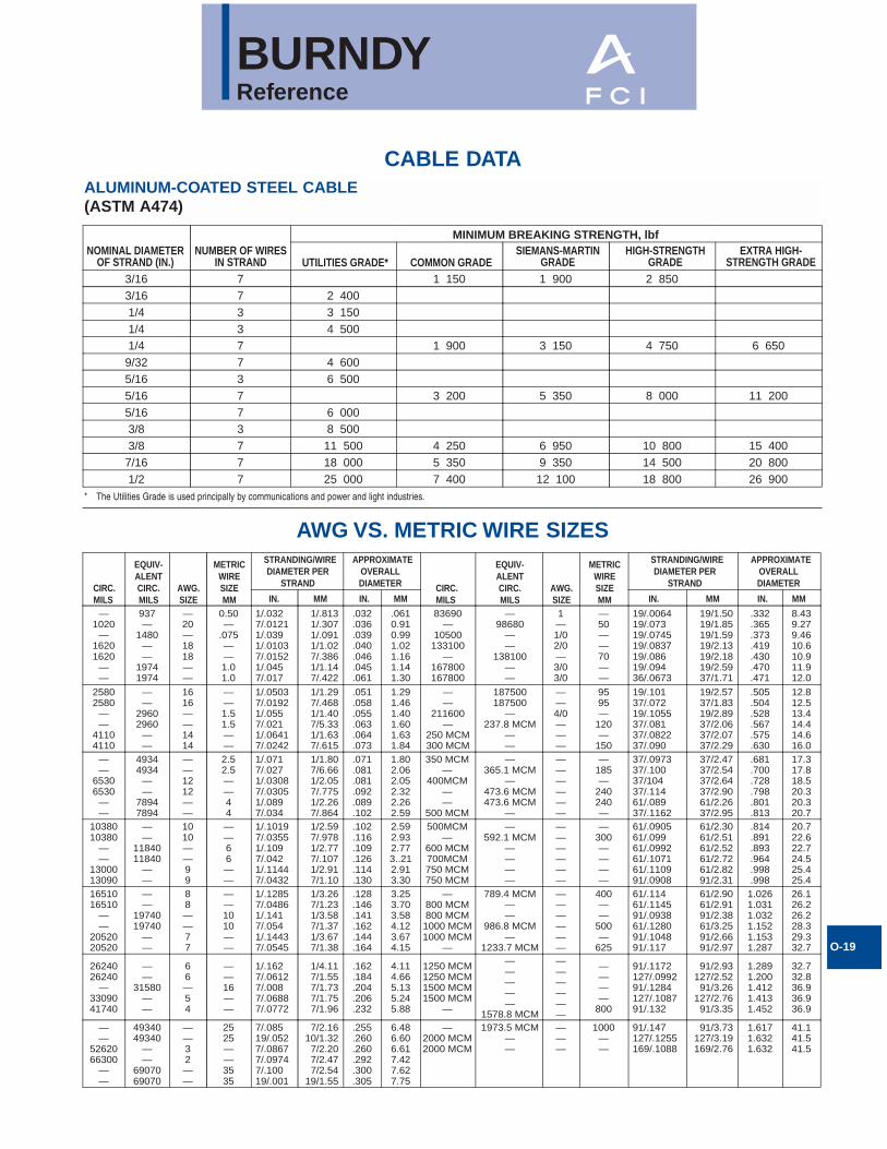
AWG VS. METRIC WIRE SIZES
ALUMINUM-COATED STEEL CABLE(ASTM A474)
MINIMUM BREAKING STRENGTH, lbfNOMINAL DIAMETER
OF STRAND (IN.)NUMBER OF WIRES
IN STRANDSIEMANS-MARTIN
GRADEHIGH-STRENGTH
GRADEEXTRA HIGH-
STRENGTH GRADEUTILITIES GRADE* COMMON GRADE3/16 7 1 150 1 900 2 8503/16 7 2 4001/4 3 3 1501/4 3 4 5001/4 7 1 900 3 150 4 750 6 650
9/32 7 4 6005/16 3 6 5005/16 7 3 200 5 350 8 000 11 2005/16 7 6 0003/8 3 8 5003/8 7 11 500 4 250 6 950 10 800 15 400
7/16 7 18 000 5 350 9 350 14 500 20 8001/2 7 25 000 7 400 12 100 18 800 26 900
CIRC.MILS
EQUIV-ALENTCIRC.MILS
METRICWIRESIZEMM
AWG.SIZE
STRANDING/WIREDIAMETER PER
STRAND
APPROXIMATEOVERALLDIAMETER
IN. MM IN. MMCIRC.MILS
EQUIV-ALENTCIRC.MILS
METRICWIRESIZEMM
AWG.SIZE
STRANDING/WIREDIAMETER PER
STRAND
APPROXIMATEOVERALLDIAMETER
IN. MM IN. MM
—1020
—16201620
——
937—
1480——
19741974
—20—1818——
0.50—
.075——1.01.0
1/.0327/.01211/.0391/.01037/.01521/.0457/.017
1/.8131/.3071/.0911/1.027/.3861/1.147/.422
.032
.036
.039
.040
.046
.045
.061
.0610.910.991.021.161.141.30
1—1/02/0—3/03/0
—50——70——
19/.006419/.07319/.074519/.083719/.08619/.09436/.0673
19/1.5019/1.8519/1.5919/2.1319/2.1819/2.5937/1.71
.332
.365
.373
.419
.430
.470
.471
8.439.279.4610.610.911.912.0
25802580
——
41104110
——
29602960
——
1616——1414
——1.51.5——
1/.05037/.01921/.0557/.0211/.06417/.0242
1/1.297/.4681/1.407/5.331/1.637/.615
.051
.058
.055
.063
.064
.073
1.291.461.401.601.631.84
——4/0———
9595—
120—
150
19/.10137/.07219/.105537/.08137/.082237/.090
19/2.5737/1.8319/2.8937/2.0637/2.0737/2.29
.505
.504
.528
.567
.575
.630
12.812.513.414.414.616.0
——
65306530
——
49344934
——
78947894
——1212——
2.52.5——44
1/.0717/.0271/.03087/.03051/.0897/.034
1/1.807/6.661/2.057/.7751/2.267/.864
.071
.081
.081
.092
.089
.102
1.802.062.052.322.262.59
——————
—185—
240240—
37/.097337/.10037/10437/.11461/.08937/.1162
37/2.4737/2.5437/2.6437/2.9061/2.2637/2.95
.681
.700
.728
.798
.801
.813
17.317.818.520.320.320.7
1038010380
——
1300013090
——
1184011840
——
1010——99
——66——
1/.10197/.03551/.1097/.0421/.11447/.0432
1/2.597/.9781/2.777/.1071/2.917/1.10
.102
.116
.109
.126
.114
.130
2.592.932.773..212.913.30
——————
—300————
61/.090561/.09961/.099261/.107161/.110991/.0908
61/2.3061/2.5161/2.5261/2.7261/2.8291/2.31
.814
.891
.893
.964
.998
.998
20.722.622.724.525.425.4
1651016510
——
2052020520
——
1974019740
——
88——77
——1010——
1/.12857/.04861/.1417/.0541/.14437/.0545
1/3.267/1.231/3.587/1.371/3.677/1.38
.128
.146
.141
.162
.144
.164
3.253.703.584.123.674.15
——————
400——
500—
625
61/.11461/.114591/.093861/.128091/.104891/.117
61/2.9061/2.9191/2.3861/3.2591/2.6691/2.97
1.0261.0311.0321.1521.1531.287
26.126.226.228.329.332.7
2624026240
—3309041740
——
31580——
66—54
——16——
1/.1627/.06127/.0087/.06887/.0772
1/4.117/1.557/1.737/1.757/1.96
.162
.184
.204
.206
.232
4.114.665.135.245.88
——————
————
800
91/.1172127/.099291/.1284127/.108791/.132
91/2.93127/2.5291/3.26
127/2.7691/3.35
1.2891.2001.4121.4131.452
32.732.836.936.936.9
——
5262066300
——
4934049340
——
6907069070
——32——
2525——3535
7/.08519/.0527/.08677/.09747/.10019/.001
7/2.1610/1.327/2.207/2.477/2.54
19/1.55
.255
.260
.260
.292
.300
.305
6.486.606.617.427.627.75
———
—98680
——
138100——
187500187500
—237.8 MCM
———
365.1 MCM—
473.6 MCM473.6 MCM
——
592.1 MCM————
789.4 MCM——
986.8 MCM—
1233.7 MCM—————
1578.8 MCM1973.5 MCM
——
1000——
83690—
10500133100
—167800167800
——
211600—
250 MCM300 MCM350 MCM
—400MCM
——
500 MCM500MCM
—600 MCM700MCM750 MCM750 MCM
—800 MCM800 MCM1000 MCM1000 MCM
—
1250 MCM1250 MCM1500 MCM1500 MCM
—
—2000 MCM2000 MCM
91/.147127/.1255169/.1088
91/3.73127/3.19169/2.76
1.6171.6321.632
41.141.541.5
* The Utilities Grade is used principally by communications and power and light industries.
BURNDYReference
O-20
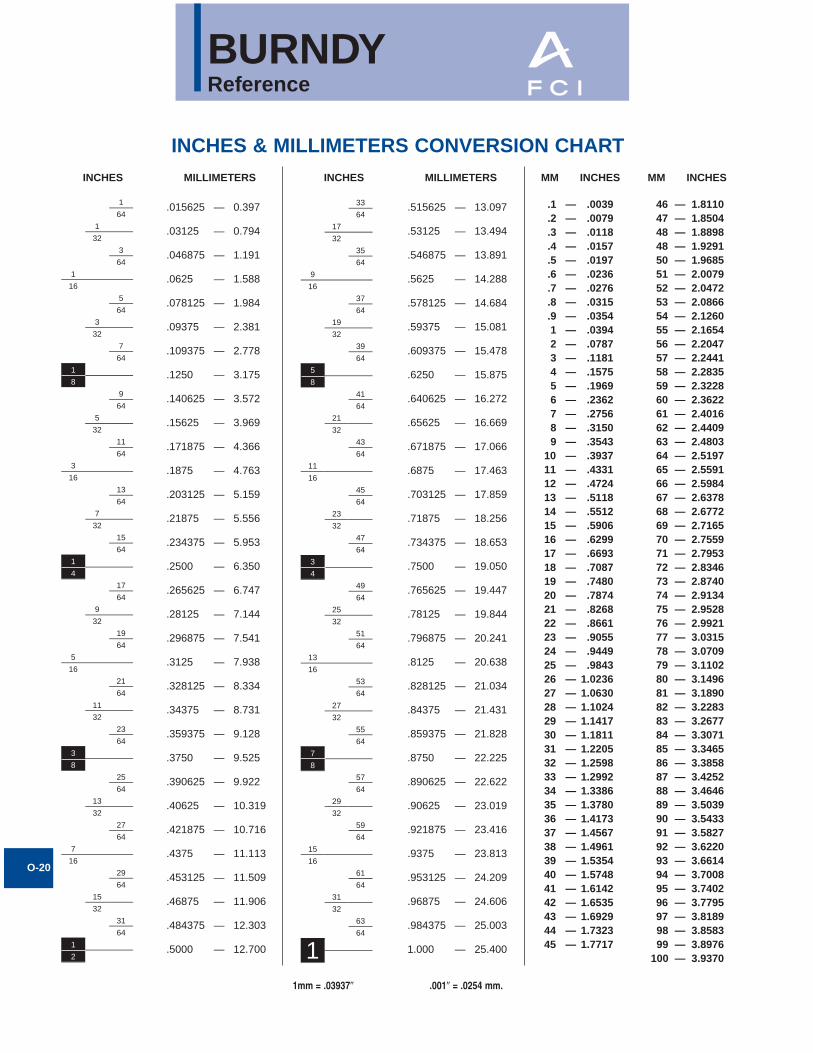
INCHES & MILLIMETERS CONVERSION CHART
1
64
1
32
3
64
1
16
5
64
3
32
7
64
1
8
9
64
5
32
11
64
3
16
13
64
7
32
15
64
1
4
17
64
9
32
19
64
5
16
21
64
11
32
23
64
3
8
25
64
13
32
27
64
7
16
29
64
15
32
31
64
1
2
.015625 — 0.397
.03125 — 0.794
.046875 — 1.191
.0625 — 1.588
.078125 — 1.984
.09375 — 2.381
.109375 — 2.778
.1250 — 3.175
.140625 — 3.572
.15625 — 3.969
.171875 — 4.366
.1875 — 4.763
.203125 — 5.159
.21875 — 5.556
.234375 — 5.953
.2500 — 6.350
.265625 — 6.747
.28125 — 7.144
.296875 — 7.541
.3125 — 7.938
.328125 — 8.334
.34375 — 8.731
.359375 — 9.128
.3750 — 9.525
.390625 — 9.922
.40625 — 10.319
.421875 — 10.716
.4375 — 11.113
.453125 — 11.509
.46875 — 11.906
.484375 — 12.303
.5000 — 12.700
INCHES MILLIMETERS
33
64
17
32
35
64
9
16
37
64
19
32
39
64
5
8
41
64
21
32
43
64
11
16
45
64
23
32
47
64
3
4
49
64
25
32
51
64
13
16
53
64
27
32
55
64
7
1
8
57
64
29
32
59
64
15
16
61
64
31
32
63
64
.515625 — 13.097
.53125 — 13.494
.546875 — 13.891
.5625 — 14.288
.578125 — 14.684
.59375 — 15.081
.609375 — 15.478
.6250 — 15.875
.640625 — 16.272
.65625 — 16.669
.671875 — 17.066
.6875 — 17.463
.703125 — 17.859
.71875 — 18.256
.734375 — 18.653
.7500 — 19.050
.765625 — 19.447
.78125 — 19.844
.796875 — 20.241
.8125 — 20.638
.828125 — 21.034
.84375 — 21.431
.859375 — 21.828
.8750 — 22.225
.890625 — 22.622
.90625 — 23.019
.921875 — 23.416
.9375 — 23.813
.953125 — 24.209
.96875 — 24.606
.984375 — 25.003
1.000 — 25.400
INCHES MM
.1 — .0039
.2 — .0079
.3 — .0118
.4 — .0157
.5 — .0197
.6 — .0236
.7 — .0276
.8 — .0315
.9 — .0354 1 — .0394 2 — .0787 3 — .1181 4 — .1575 5 — .1969 6 — .2362 7 — .2756 8 — .3150 9 — .3543
10 — .393711 — .433112 — .472413 — .511814 — .551215 — .590616 — .629917 — .669318 — .708719 — .748020 — .787421 — .826822 — .866123 — .905524 — .944925 — .984326 — 1.023627 — 1.063028 — 1.102429 — 1.141730 — 1.181131 — 1.220532 — 1.259833 — 1.299234 — 1.338635 — 1.378036 — 1.417337 — 1.456738 — 1.496139 — 1.535440 — 1.574841 — 1.614242 — 1.653543 — 1.692944 — 1.732345 — 1.7717
INCHES MM
46 — 1.811047 — 1.850448 — 1.889848 — 1.929150 — 1.968551 — 2.007952 — 2.047253 — 2.086654 — 2.126055 — 2.165456 — 2.204757 — 2.244158 — 2.283559 — 2.322860 — 2.362261 — 2.401662 — 2.440963 — 2.480364 — 2.519765 — 2.559166 — 2.598467 — 2.637868 — 2.677269 — 2.716570 — 2.755971 — 2.795372 — 2.834673 — 2.874074 — 2.913475 — 2.952876 — 2.992177 — 3.031578 — 3.070979 — 3.110280 — 3.149681 — 3.189082 — 3.228383 — 3.267784 — 3.307185 — 3.346586 — 3.385887 — 3.425288 — 3.464689 — 3.503990 — 3.543391 — 3.582792 — 3.622093 — 3.661494 — 3.700895 — 3.740296 — 3.779597 — 3.818998 — 3.858399 — 3.8976
100 — 3.9370
INCHESMILLIMETERS
1mm = .03937� .001� = .0254 mm.
BURNDYReference
O-21
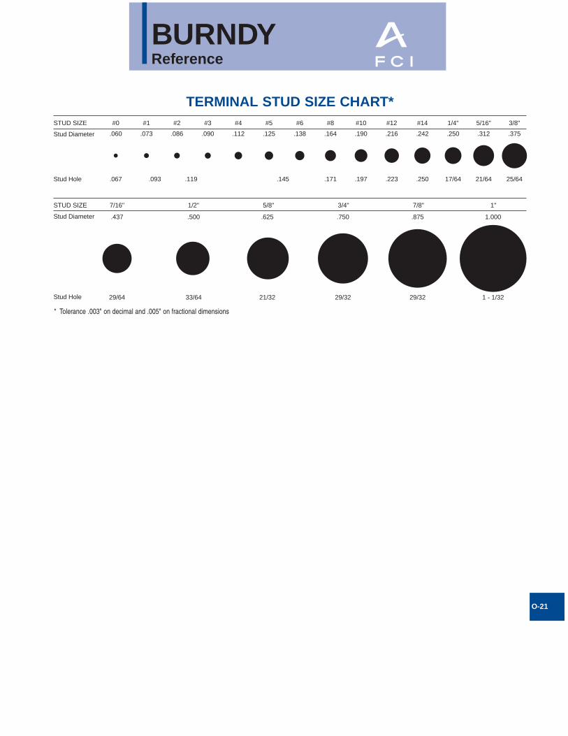
TERMINAL STUD SIZE CHART*STUD SIZE #0 #1 #2 #3 #4 #5 #6 #8 #10 #12 #14 1/4" 5/16" 3/8"
.060
.437 .500 .625 .750 .875 1.000
29/64 33/64 21/32 29/32 29/32 1 - 1/32
.073 .086 .090 .112 .125 .138 .164 .190 .216 .242 .250 .312
.067 .093 .119 .145 .171 .197 .223 .250 17/64 21/64
.375
25/64
Stud Diameter
Stud Hole
STUD SIZE 7/16" 1/2" 5/8" 3/4" 7/8" 1"
Stud Diameter
Stud Hole
* Tolerance .003" on decimal and .005" on fractional dimensions
BURNDYReference
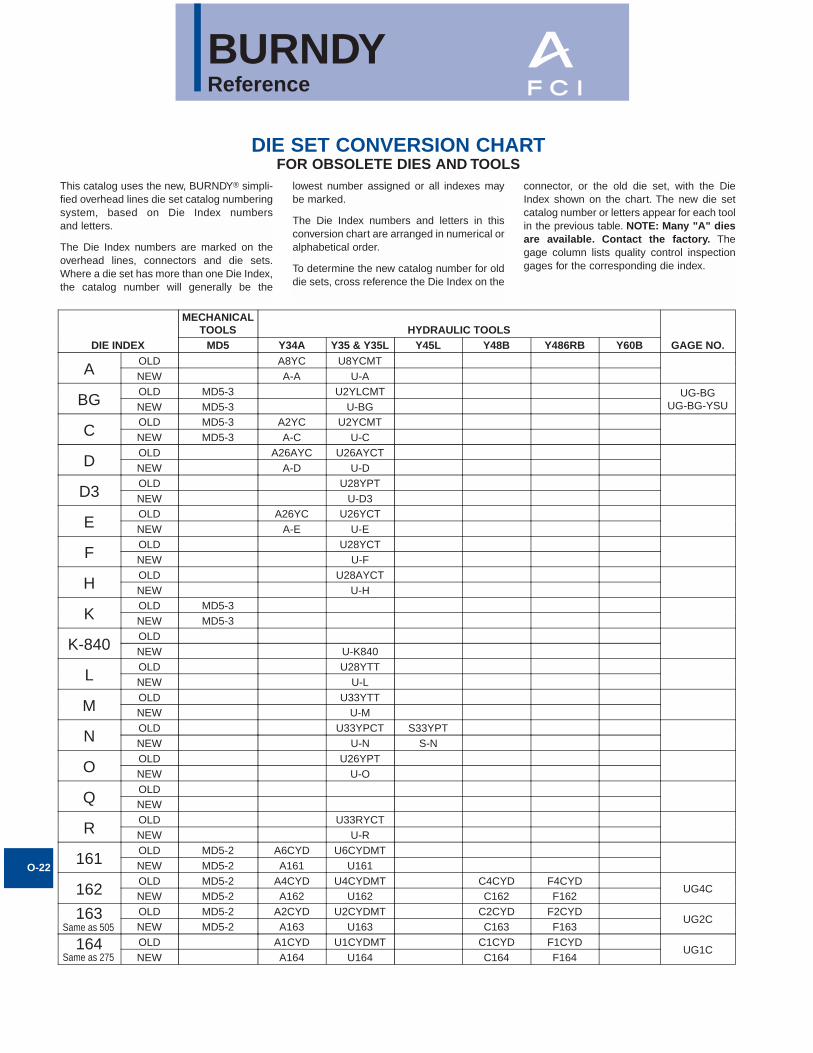
This catalog uses the new, BURNDY® simpli-fied overhead lines die set catalog numberingsystem, based on Die Index numbers and letters.
The Die Index numbers are marked on theoverhead lines, connectors and die sets.Where a die set has more than one Die Index,the catalog number will generally be the
lowest number assigned or all indexes may be marked.
The Die Index numbers and letters in thisconversion chart are arranged in numerical oralphabetical order.
To determine the new catalog number for olddie sets, cross reference the Die Index on the
connector, or the old die set, with the DieIndex shown on the chart. The new die setcatalog number or letters appear for each toolin the previous table. NOTE: Many "A" diesare available. Contact the factory. Thegage column lists quality control inspectiongages for the corresponding die index.
O-22
DIE SET CONVERSION CHARTFOR OBSOLETE DIES AND TOOLS
DIE INDEX
MECHANICALTOOLS HYDRAULIC TOOLS
GAGE NO.MD5 Y34A Y35 & Y35L Y45L Y48B Y486RB Y60B
AOLD A8YC U8YCMTNEW A-A U-A
BGOLD MD5-3 U2YLCMT UG-BG
UG-BG-YSUNEW MD5-3 U-BG
COLD MD5-3 A2YC U2YCMTNEW MD5-3 A-C U-C
DOLD A26AYC U26AYCTNEW A-D U-D
D3OLD U28YPTNEW U-D3
EOLD A26YC U26YCTNEW A-E U-E
FOLD U28YCTNEW U-F
HOLD U28AYCTNEW U-H
KOLD MD5-3NEW MD5-3
K-840OLDNEW U-K840
LOLD U28YTTNEW U-L
MOLD U33YTTNEW U-M
NOLD U33YPCT S33YPTNEW U-N S-N
OOLD U26YPTNEW U-O
QOLDNEW
ROLD U33RYCTNEW U-R
161OLD MD5-2 A6CYD U6CYDMTNEW MD5-2 A161 U161
162OLD MD5-2 A4CYD U4CYDMT C4CYD F4CYD
UG4CNEW MD5-2 A162 U162 C162 F162
163 OLD MD5-2 A2CYD U2CYDMT C2CYD F2CYDUG2C
NEW MD5-2 A163 U163 C163 F163
164 OLD A1CYD U1CYDMT C1CYD F1CYDUG1C
NEW A164 U164 C164 F164
Same as 505
Same as 275
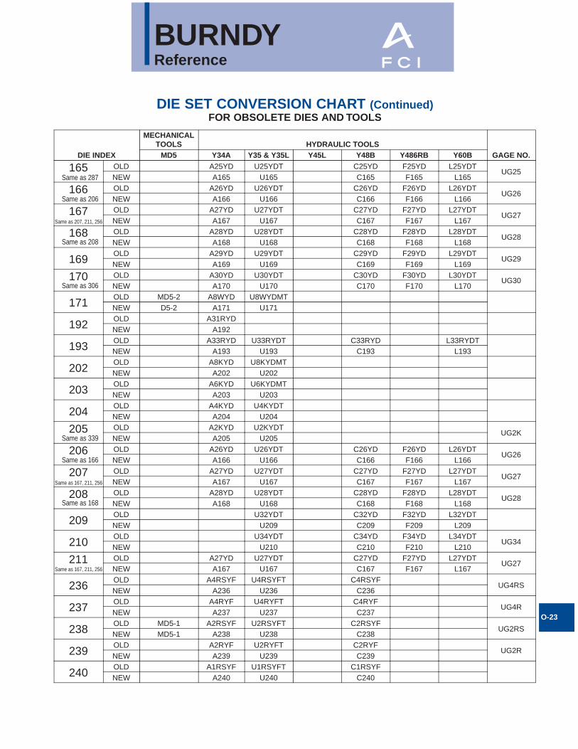
BURNDYReference
O-23
DIE SET CONVERSION CHART (Continued)FOR OBSOLETE DIES AND TOOLS
DIE INDEX
MECHANICALTOOLS HYDRAULIC TOOLS
GAGE NO.MD5 Y34A Y35 & Y35L Y45L Y48B Y486RB Y60B
165 OLD A25YD U25YDT C25YD F25YD L25YDTUG25
NEW A165 U165 C165 F165 L165
166 OLD A26YD U26YDT C26YD F26YD L26YDTUG26
NEW A166 U166 C166 F166 L166
167 OLD A27YD U27YDT C27YD F27YD L27YDTUG27
NEW A167 U167 C167 F167 L167
168 OLD A28YD U28YDT C28YD F28YD L28YDTUG28
NEW A168 U168 C168 F168 L168
169OLD A29YD U29YDT C29YD F29YD L29YDT
UG29NEW A169 U169 C169 F169 L169
170 OLD A30YD U30YDT C30YD F30YD L30YDTUG30
NEW A170 U170 C170 F170 L170
171OLD MD5-2 A8WYD U8WYDMTNEW D5-2 A171 U171
192OLD A31RYDNEW A192
193OLD A33RYD U33RYDT C33RYD L33RYDTNEW A193 U193 C193 L193
202OLD A8KYD U8KYDMTNEW A202 U202
203OLD A6KYD U6KYDMTNEW A203 U203
204OLD A4KYD U4KYDTNEW A204 U204
205 OLD A2KYD U2KYDTUG2K
NEW A205 U205
206 OLD A26YD U26YDT C26YD F26YD L26YDTUG26
NEW A166 U166 C166 F166 L166
207 OLD A27YD U27YDT C27YD F27YD L27YDTUG27
NEW A167 U167 C167 F167 L167
208 OLD A28YD U28YDT C28YD F28YD L28YDTUG28
NEW A168 U168 C168 F168 L168
209OLD U32YDT C32YD F32YD L32YDTNEW U209 C209 F209 L209
210OLD U34YDT C34YD F34YD L34YDT
UG34NEW U210 C210 F210 L210
211 OLD A27YD U27YDT C27YD F27YD L27YDTUG27
NEW A167 U167 C167 F167 L167
236OLD A4RSYF U4RSYFT C4RSYF
UG4RSNEW A236 U236 C236
237OLD A4RYF U4RYFT C4RYF
UG4RNEW A237 U237 C237
238OLD MD5-1 A2RSYF U2RSYFT C2RSYF
UG2RSNEW MD5-1 A238 U238 C238
239OLD A2RYF U2RYFT C2RYF
UG2RNEW A239 U239 C239
240OLD A1RSYF U1RSYFT C1RSYFNEW A240 U240 C240
Same as 287
Same as 206
Same as 208
Same as 306
Same as 339
Same as 166
Same as 168
Same as 207, 211, 256
Same as 167, 211, 256
Same as 167, 211, 256
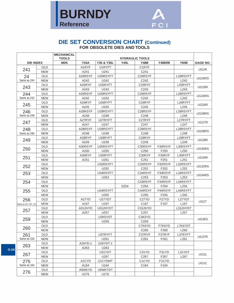
BURNDYReference
O-24
DIE SET CONVERSION CHART (Continued)FOR OBSOLETE DIES AND TOOLS
DIE INDEX
MECHANICALTOOLS HYDRAULIC TOOLS
GAGE NO.MD5 Y34A Y35 & Y35L Y45L Y48B Y486RB Y60B
241OLD A1RYF U1RYFT C1RYF
UG1RNEW A241 U241 C241
24 OLD A26RSYF U26RSYFT C26RSYF L26RSYFTUG26RS
NEW A242 U242 C242 L242
243OLD A25RYF U25RYFT C25RYF L25RYFT
UG25RNEW A243 U243 C243 L243
244 OLD A26RSYF U26RSYFT C26RSYF L26RSYFTUG26RS
NEW A242 U242 C242 L242
245OLD A26RYF U26RYFT C26RYF L26RYFT
UG26RNEW A245 U245 C245 L245
246 OLD A28RSYF U28RSYFT C28RSYF L28RSYFTUG28RS
NEW A248 U248 C248 L248
247OLD A27RYF U27RYFT C27RYF L27RYFT
UG27RNEW A247 U247 C247 L247
248 OLD A28RSYF U28RSYFT C28RSYF L28RSYFTUG28RS
NEW A248 U248 C248 L248
249OLD A28RYF U28RYFT C28RYF L28RYFT
UG28RNEW A249 U249 C249 L249
250OLD A30RSYF U30RSYFT C30RSYF F30RSYF L30RSYFT
UG30RSNEW A250 U250 C250 F250 L250
251OLD A30RYF U30RYFT C30RYF F30RYF L30RYFT
UG30RNEW A251 U251 C251 F251 L251
252OLD U32RSYFT C32RSYF F32RSYF L32RSYFT
UG32RSNEW U252 C252 F252 L252
253 OLD U34RSYFT C34RSYF F34RSYF L34RSYFTUG34RS
NEW U253 C253 F253 L253
254 OLD C43RSYF F34RSYF L34RSYFTNEW S254 C254 F254 L254
255 OLD U44RSYFT C44RSYF F44RSYF L44RSYFTNEW U255 C255 F255 L255
256 OLD A27YD U27YDT C27YD F27YD L27YDTUG27
NEW A167 U167 C167 F167 L167
257OLD A312HYD U312HYDT C312HYD L312HYDTNEW A257 U257 C257 L257
259OLD U3K5YDT C3K5YD
UG3K5NEW U259 C259
260OLD C7K6YD F7K6YD L7K6YDTNEW C260 F260 L260
261 OLD U37RYFT C37RYF F37RYF L37RYFTUG37R
NEW U261 C261 F261 L261
263OLD A26YD-1 U26YDT-1NEW A263 U263
267OLD U31YDT C31YD F31YD L31YDT
UG31NEW U267 C267 F267 L267
275 OLD A1CYD U1CYDMT C1CYD F1CYDUG1C
NEW A164 U164 C164 F164
276OLD A6WKYD U6WKYDTNEW A276 U276
Same as 244
Same as 242
Same as 248
Same as 246
Same as 318
Same as 164
Same as 167, 207, 211
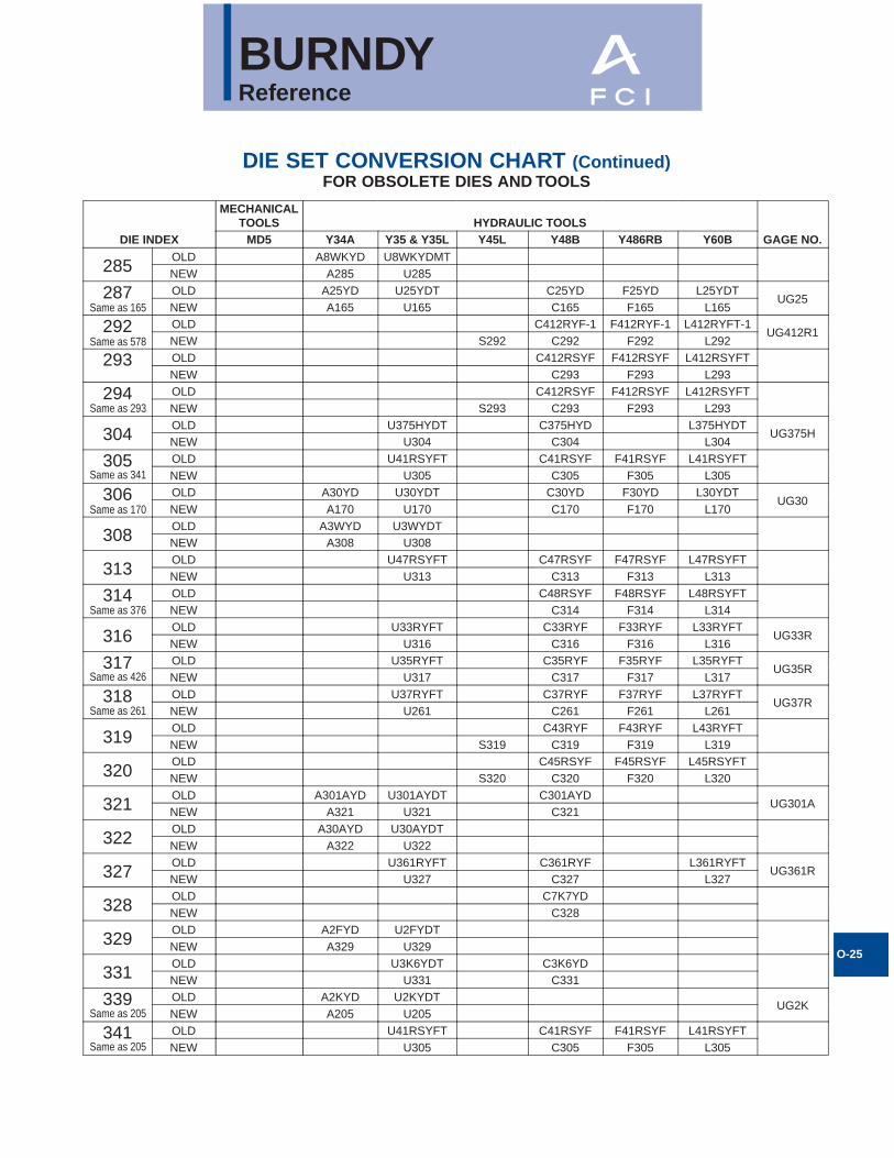
BURNDYReference
O-25
DIE SET CONVERSION CHART (Continued)FOR OBSOLETE DIES AND TOOLS
DIE INDEX
MECHANICALTOOLS HYDRAULIC TOOLS
GAGE NO.MD5 Y34A Y35 & Y35L Y45L Y48B Y486RB Y60B
285OLD A8WKYD U8WKYDMTNEW A285 U285
287 OLD A25YD U25YDT C25YD F25YD L25YDTUG25
NEW A165 U165 C165 F165 L165
292 OLD C412RYF-1 F412RYF-1 L412RYFT-1UG412R1
NEW S292 C292 F292 L292
293 OLD C412RSYF F412RSYF L412RSYFTNEW C293 F293 L293
294 OLD C412RSYF F412RSYF L412RSYFTNEW S293 C293 F293 L293
304OLD U375HYDT C375HYD L375HYDT
UG375HNEW U304 C304 L304
305 OLD U41RSYFT C41RSYF F41RSYF L41RSYFTNEW U305 C305 F305 L305
306 OLD A30YD U30YDT C30YD F30YD L30YDTUG30
NEW A170 U170 C170 F170 L170
308OLD A3WYD U3WYDTNEW A308 U308
313OLD U47RSYFT C47RSYF F47RSYF L47RSYFTNEW U313 C313 F313 L313
314 OLD C48RSYF F48RSYF L48RSYFTNEW C314 F314 L314
316OLD U33RYFT C33RYF F33RYF L33RYFT
UG33RNEW U316 C316 F316 L316
317 OLD U35RYFT C35RYF F35RYF L35RYFTUG35R
NEW U317 C317 F317 L317
318 OLD U37RYFT C37RYF F37RYF L37RYFTUG37R
NEW U261 C261 F261 L261
319OLD C43RYF F43RYF L43RYFTNEW S319 C319 F319 L319
320OLD C45RSYF F45RSYF L45RSYFTNEW S320 C320 F320 L320
321OLD A301AYD U301AYDT C301AYD
UG301ANEW A321 U321 C321
322OLD A30AYD U30AYDTNEW A322 U322
327OLD U361RYFT C361RYF L361RYFT
UG361RNEW U327 C327 L327
328OLD C7K7YDNEW C328
329OLD A2FYD U2FYDTNEW A329 U329
331OLD U3K6YDT C3K6YDNEW U331 C331
339 OLD A2KYD U2KYDTUG2K
NEW A205 U205
341 OLD U41RSYFT C41RSYF F41RSYF L41RSYFTNEW U305 C305 F305 L305
Same as 165
Same as 578
Same as 293
Same as 170
Same as 376
Same as 426
Same as 261
Same as 205
Same as 205
Same as 341
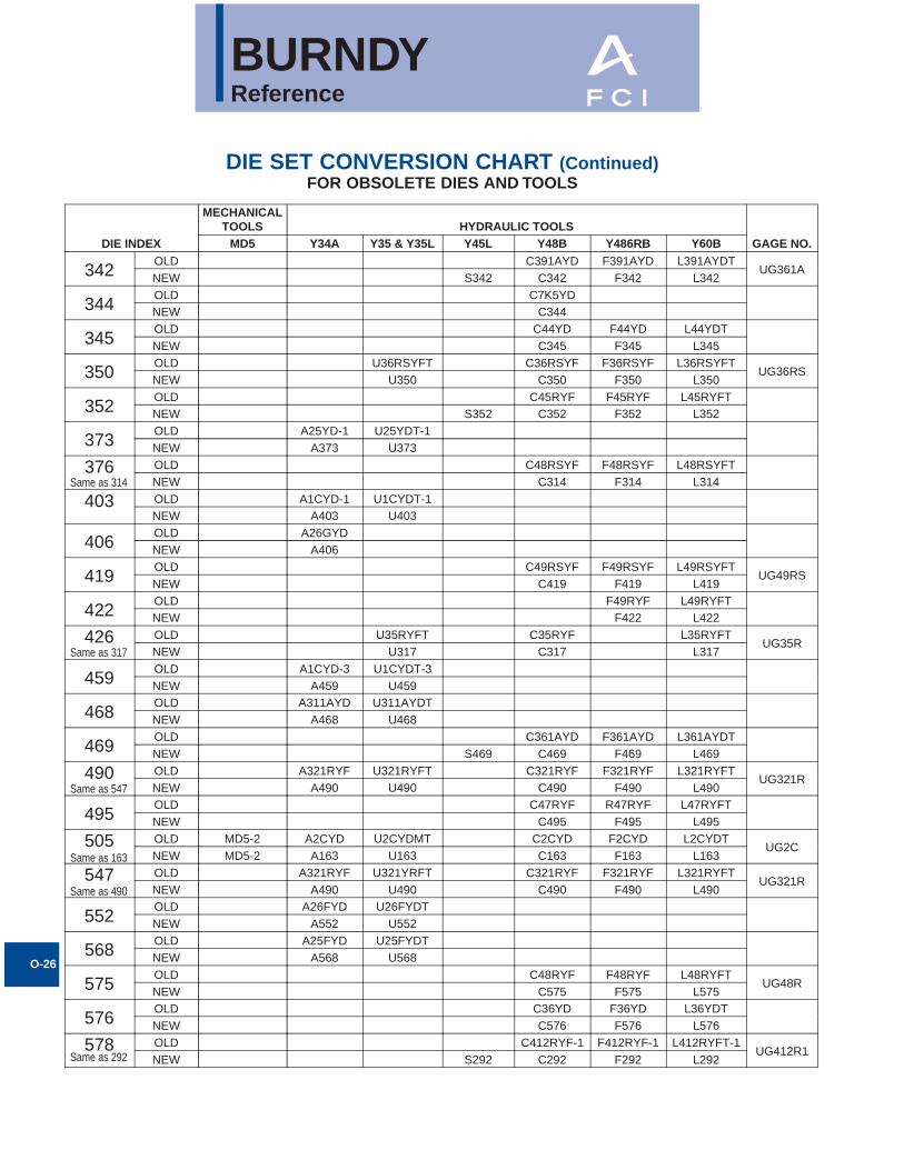
BURNDYReference
O-26
DIE SET CONVERSION CHART (Continued)FOR OBSOLETE DIES AND TOOLS
DIE INDEX
MECHANICALTOOLS HYDRAULIC TOOLS
GAGE NO.MD5 Y34A Y35 & Y35L Y45L Y48B Y486RB Y60B
342OLD C391AYD F391AYD L391AYDT
UG361ANEW S342 C342 F342 L342
344OLD C7K5YDNEW C344
345OLD C44YD F44YD L44YDTNEW C345 F345 L345
350OLD U36RSYFT C36RSYF F36RSYF L36RSYFT
UG36RSNEW U350 C350 F350 L350
352OLD C45RYF F45RYF L45RYFTNEW S352 C352 F352 L352
373OLD A25YD-1 U25YDT-1NEW A373 U373
376 OLD C48RSYF F48RSYF L48RSYFTNEW C314 F314 L314
403 OLD A1CYD-1 U1CYDT-1NEW A403 U403
406OLD A26GYDNEW A406
419OLD C49RSYF F49RSYF L49RSYFT
UG49RSNEW C419 F419 L419
422OLD F49RYF L49RYFTNEW F422 L422
426 OLD U35RYFT C35RYF L35RYFTUG35R
NEW U317 C317 L317
459OLD A1CYD-3 U1CYDT-3NEW A459 U459
468OLD A311AYD U311AYDTNEW A468 U468
469OLD C361AYD F361AYD L361AYDTNEW S469 C469 F469 L469
490 OLD A321RYF U321RYFT C321RYF F321RYF L321RYFTUG321R
NEW A490 U490 C490 F490 L490
495OLD C47RYF R47RYF L47RYFTNEW C495 F495 L495
505 OLD MD5-2 A2CYD U2CYDMT C2CYD F2CYD L2CYDTUG2C
NEW MD5-2 A163 U163 C163 F163 L163
547 OLD A321RYF U321YRFT C321RYF F321RYF L321RYFTUG321R
NEW A490 U490 C490 F490 L490
552OLD A26FYD U26FYDTNEW A552 U552
568OLD A25FYD U25FYDTNEW A568 U568
575OLD C48RYF F48RYF L48RYFT
UG48RNEW C575 F575 L575
576OLD C36YD F36YD L36YDTNEW C576 F576 L576
578 OLD C412RYF-1 F412RYF-1 L412RYFT-1UG412R1
NEW S292 C292 F292 L292
Same as 314
Same as 317
Same as 547
Same as 163
Same as 490
Same as 292

BURNDYReference
O-27
DIE SET CONVERSION CHART (Continued)FOR OBSOLETE DIES AND TOOLS
DIE INDEX
MECHANICALTOOLS HYDRAULIC TOOLS
GAGE NO.MD5 Y34A Y35 & Y35L Y45L Y48B Y486RB Y60B
579OLD C451RYF F451RYF L451RYFTNEW C579 F579 L579
607OLD U281UYDTNEW U607
608OLD U39RYFT C39RYF F39RYF L39RYFTNEW U608 C608 F608 L608
609OLD A250EYD U250EYDT C250EYDNEW A609 U609 C609
614OLD C38RYFNEW C614
616OLD A29AYDNEW A616
627OLD C39YD F39YD L39YDTNEW C627 F627 L627
642OLD U32LYDT C32LYDNEW U642 C642
643OLD U32RLYDTNEW U643
648OLD F49RYF-1 L49RYFT-1
UG49RNEW F648 L648
654OLD A28RLYR U28RLYRT L28RLYRTNEW A654 U654 L654
655OLD U321RLYRTNEW U655
657OLD C39LYRNEW C657
658OLD A27RLYR U27RLYRT
UG27RLNEW A658 U658
659OLD A26RLYR U26RLYRT
UG26RLNEW A659 U659
660OLD A25RLYR U25RLYRTNEW A660 U660
667OLD C36RLYR-1NEW C667
668OLD U7M8YRTNEW U668
676OLD U7M10YRTNEW U676
677OLD U7M9YRT
UG7M9NEW U677
678OLD U7M7YRTNEW U678
679OLD U7M6YRTNEW U679
684OLD F51RYR L51RYRTNEW F684 L684
687OLDNEW
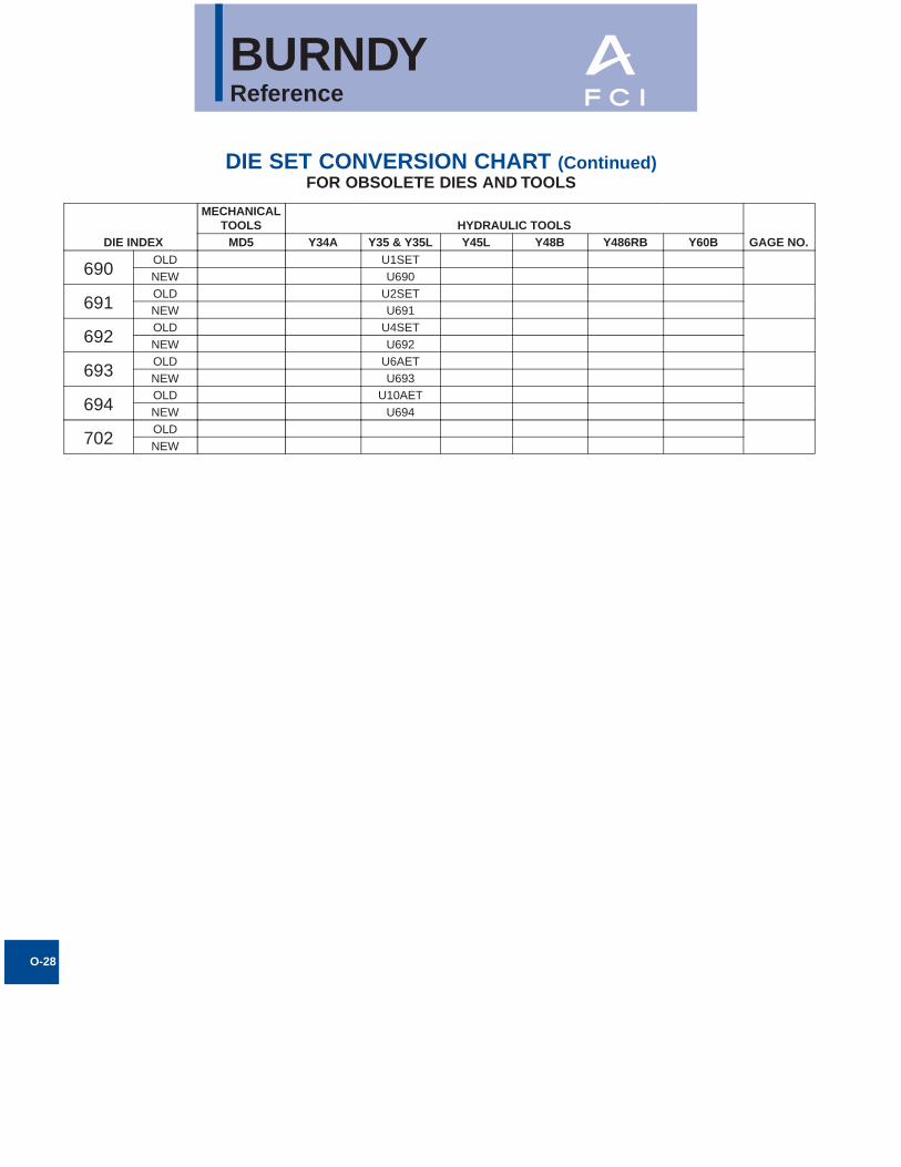
BURNDYReference
O-28
DIE SET CONVERSION CHART (Continued)FOR OBSOLETE DIES AND TOOLS
DIE INDEX
MECHANICALTOOLS HYDRAULIC TOOLS
GAGE NO.MD5 Y34A Y35 & Y35L Y45L Y48B Y486RB Y60B
690OLD U1SETNEW U690
691OLD U2SETNEW U691
692OLD U4SETNEW U692
693OLD U6AETNEW U693
694OLD U10AETNEW U694
702OLDNEW

BURNDYReference
O-29
BURNDY CONDUCTOR NUMBERING SYSTEMCOPYRIGHT 1940 BY BURNDY ENGINEERING CO., INC.
OUTSIDEDIA.IN.
OUTSIDEDIA.MM.
STR. CABLE SOL. WIRE AREAMM2
A.C.S.R. PIPE SIZE CONDUCTOR TUBE & ROD
SERVIT NO.Cat.No. Size
Cat.No. Size Copper Cable
Cat.No. Cable Size Cat. No. ST D
Cat.No.
ExHvy
Cat.No. Dia.
.102 2.594 10W 10 5.261 KS90
.114 2.896 9W 9 6.634
.116 2.946 10 C 10 5.261
.125 3.175 60 1/8
.129 3.277 8W 8 8.366 KS15
.130 3.302 9 C 9 6.634
.144 3.658 7W 7 10.550
.146 3.708 8 C 8 8.366
.158 4.013 8R 8
.162 4.115 6W 6 13.300 KS17
.164 4.166 7 C 7 10.550
.176 4.470 7R 7
.182 4.597 5W 5 16.770
.184 4.648 6 C 6 13.300
.198 5.029 6R 6
.204 5.182 4W 4 21.150 KS20
.206 5.258 5 C 5 16.770
.223 5.664 5R 5
.229 5.817 3W 3 26.670
.232 5.867 4 C 4 21.150
.250 6.350 4R 4 61 1/4
.258 6.553 2W 2 33.630 KS22
.260 6.629 3 C 3 2.6670
.281 7.137 3R 3
.289 7.344 1W 1 42.410
.292 7.394 2 C 2 33.630 KS23
.316 8.026 2R 2
.325 8.255 75 1/0 53.480
.332 8.382 1 C 1 42.410
.355 9.017 1R 1
.365 9.274 76 2/0 67.430
.372 9.474 25 1/0 53.480 KS25
.375 9.525 62 3/8
.398 10.109 25R 1/0
.405 10.287 10 1/8 50 1/8
.410 10.414 77 3/0 85.030
.419 10.617 26 2/0 67.430 KS26
.447 11.354 26R 2/0
.460 11.684 78 4/0 107.20
.470 11.938 27 3/0 85.03
.500 12.700 63 1/2
.502 12.725 27R 3/0
.528 13.414 28 4/0 107.20 KS28
.540 13.716 11 1/4 51 1/4
.563 14.326 28R 4/0
.575 14.605 29 250 127.00
.630 16.002 30 300 152.00
.633 16.078 29R 266,800
.642 16.307 30R 266,800
.675 17.145 12 3/8 52 3/8
.680 17.272 31R 300,000
.681 17.297 31 350 177.00 KS31
.721 18.313 32R 336,400
.728 18.494 32 400 203.00
.741 18.824 33R 336,400
.750 19.050 64 3/4
.772 19.609 33 450 228.00
.783 19.888 34R 397,500
.806 20.472 35R 397,500
.813 20.676 34 500 253.00
.840 21.336 13 1/2 53 1/2
.855 21.717 35 550 279.00 KS34
.858 21.742 36R 477,000
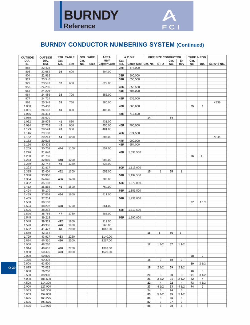
BURNDYReference
O-30
BURNDY CONDUCTOR NUMBERING SYSTEM (Continued)
OUTSIDEDIA.IN.
OUTSIDEDIA.MM.
STR. CABLE SOL. WIRE A.C.S.R. PIPE SIZE CONDUCTOR TUBE & ROD
SERVIT NO.Cat.No. Size
Cat.No. Size
Cat.No. Cable Size Cat. No. ST D
Cat.No.
ExHvy
Cat.No. Dia.
.883 22.428 37R 477,000
.893 22.682 36 600 304.00
.904 22.962 38R 500,000
.927 23.546 39R 556,500
.929 23.597 37 650 329.00
.953 24.206 40R 556,500
.953 24.206 41R 605,000
.964 24.486 38 700 355.00
.977 24.714 42R 636,000
.998 25.349 39 750 380.00 KS391.000 25.400 43R 666,600 65 11.031 26.187 40 800 405.001.036 26.314 44R 715,5001.050 26.670 14 54 1.062 26.975 41 850 431.001.094 27.762 42 900 456.00 45R 795,0001.123 28.524 43 950 481.001.146 29.108 46R 874,5001.152 29.264 44 1000 507.00 KS441.162 29.515 47R 900,0001.196 30.378 48R 954,0001.209 30.709 444 1100 557.001.246 31.648 49R 1,033,5001.250 31.750 66 1 1.263 32.080 448 1200 608.001.289 32.744 45 1250 633.001.293 32.817 50R 1,113,0001.315 33.404 452 1300 659.00 15 1 55 11.338 33.960 51R 1,192,5001.364 34.646 456 1400 709.001.382 35.103 52R 1,272,0001.412 35.865 46 1500 760.001.424 36.170 53R 1,351,5001.459 37.059 464 1600 811.001.465 37.214 54R 1,431,0001.500 38.100 67 1 1/21.504 38.202 468 1700 861.001.506 38.252 55R 1,510,5001.526 38.786 47 1750 886.001.545 39.218 56R 1,590,0001.548 39.319 472 1800 912.001.590 40.386 476 1900 963.001.632 41.427 48 2000 1013.001.660 42.164 16 1 56 1 1.729 43.917 483 2250 1140.001.824 46.330 486 2500 1267.001.900 48.260 17 1 1/2 57 1 1/21.914 48.616 490 2750 1393.001.988 50.495 493 3000 1520.002.000 50.800 68 22.375 60.325 18 2 58 22.500 63.500 69 2 1/22.875 73.025 19 2 1/2 59 2 1/23.000 76.200 70 33.500 88.900 20 3 90 3 71 3 1/24.000 101.600 21 3 1/2 91 3 1/2 72 44.500 114.300 22 4 92 4 73 4 1/25.000 127.000 23 4 1/2 93 4 1/2 74 55.563 141.300 24 5 94 56.063 154.000 85 5 1/2 95 5 1/26.625 168.275 86 6 96 67.625 193.675 87 7 97 78.625 219.075 88 8 98 8
AREAMM2
Copper Cable
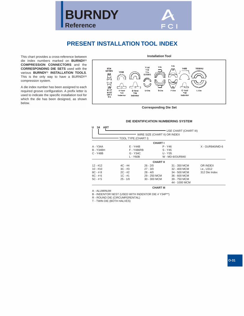
BURNDYReference
O-31
This chart provides a cross-reference betweendie index numbers marked on BURNDY®
COMPRESSION CONNECTORS and theCORRESPONDING DIE SETS used with thevarious BURNDY® INSTALLATION TOOLS.This is the only way to have a BURNDY®
compression system.
A die index number has been assigned to eachrequired groove configuration. A prefix letter isused to indicate the specific installation tool forwhich the die has been designed, as shownbelow.
PRESENT INSTALLATION TOOL INDEX
CHART IIIA - ALUMINUMB - INDENTOR NEST (USED WITH INDENTOR DIE # Y34P**)R - ROUND DIE (CIRCUMFERENTAL)T - TWIN DIE (BOTH HALVES)
CHART II12 - #1210 - #108C - # 86C - # 65C - # 5
4C - #43C - #32C - #21C - #125 - 1/0
26 - 2/027 - 3/028 - 4/029 - 250 MCM30 - 300 MCM
31 - 350 MCM32 - 400 MCM34 - 500 MCM36 - 600 MCM39 - 750 MCM44 - 1000 MCM
OR INDEXi.e., U312312 Die Index
CHART I
U 34 ART
A - Y34AB - Y34BHC - Y48B
E - Y44BF - Y486RBG - Y34CL - Y60B
P - Y46S - Y45U - Y35W - MD-6/OUR840
X - OUR840/MD-6
TOOL TYPE (CHART I)WIRE SIZE (CHART II) OR INDEX
USE CHART (CHART III)
Installation Tool
Corresponding Die Set
DIE IDENTIFICATION NUMBERING SYSTEM
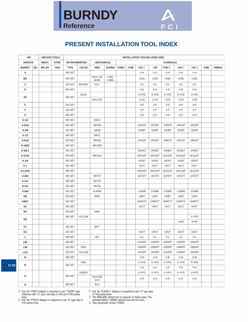
BURNDYReference
O-32
PRESENT INSTALLATION TOOL INDEX
① Cat. No. Y35P3 Adaptor is required to use "Y34PR" typeindentors with "U" type nest dies in Y35 and Y750 seriestools.
➁ Cat. No. PT6515 Adaptor is required to use "U" type dies inY45 series tools.
DIE DIELESS TOOLS INSTALLATION TOOLING USING DIES
GROOVE MECH. HYDR. DIE INFORMATION MECHANICAL HYDRAULIC
BURNDY EEI MR, MY Y644 TYPE COLOR MD6 OUR840 Y29B Y34B Y35 ➀ Y39 Y750 ➀ Y45 ➁ Y46 ➂ Y48B Y60BHU
A DIE SET U-A U-A U-A U-A U-A
BG DIE SETPerm GR
W-BGX-BG
X-NBGU-BG U-BG U-BG U-BG U-BG
C DIE SET BROWN W-C U-C U-C U-C U-C U-C
D DIE SET U-D U-D U-D U-D U-D
D3 DIE SETBLUE U-YFD U-YFD U-YFD U-YFD U-YFD
Perm GR U-D3 U-D3 U-D3 U-D3 U-D3
E DIE SET U-E U-E U-E U-E U-E
F DIE SET U-F U-F U-F U-F U-F
H DIE SET U-H U-H U-H U-H U-H
K-1/4 DIE SET WK14
K-5/16 DIE SET WK516 UK516T UK516T UK516T UK516T UK516T
K-3/8 DIE SET WK38 UK38T UK38T UK38T UK38T UK38T
K-1/2 DIE SET WK12
K-9/16 DIE SET WK916 UK916T UK916T UK916T UK916T UK916T
K-19/32 DIE SET WK1932
K-5/8-1 DIE SET UK581T UK581T UK581T UK581T UK581T
K-11/16 DIE SET WK1116 UK1116T UK1116T UK1116T UK1116T UK1116T
K-3/4 DIE SET UK34T UK34T UK34T UK34T UK34T
K-1 DIE SET UK1T UK1T UK1T UK1T UK1T
K-1-5/16 DIE SET UK1516T UK1516T UK1516T UK1516T UK1516T
K-635 DIE SET WK737 UK737T UK737T UK737T UK737T UK737T
K-747 DIE SET WK747
K-781 DIE SET WK781
K-840 DIE SET W-K840 U-K840 U-K840 U-K840 U-K840 U-K840
KB DIE SET WKB UKBT UKBT UKBT UKBT UKBT
KBKT DIE SET UKBKTT UKBKTT UKBKTT UKBKTT UKBKTT
KC DIE SET UKCT UKCT UKCT UKCT UKCT
KK DIE SET WKK
KRDIE SET YELLOW P-YFR
S-KR P-KR
KT DIE SET WKT
KU DIE SET UKUT UKUT UKUT UKUT UKUT
L DIE SET W-L U-L U-L U-L U-L U-L
L80 DIE SET — U34XRT U34XRT U34XRT U34XRT U34XRT
L99 DIE SET PINK U38XRT U38XRT U38XRT U38XRT U38XRT
L115 DIE SET YELLOW U44XRT U44XRT U44XRT U44XRT U44XRT
M DIE SET U-M U-M U-M U-M U-M
N DIE SETRED U-YFN U-YFN U-YFN U-YFN P-YFN
U-N U-N U-N S-N P-N
O DIE SETGREEN U-YFO U-YFO U-YFO U-YFO U-YFO
Perm GRW-O
U-O U-O U-O U-O U-O
Q DIE SET W-Q
➄
③ Cat. No. PUADP-1 Adaptor is required to use "U" type diesin Y46 series tools.
➃ The MD6-6R2 ratchet tool is required on these sizes. Thestandard MD6 or MD6R ratchet tools will not work.
⑤ Also pnuematic version Y29NC.
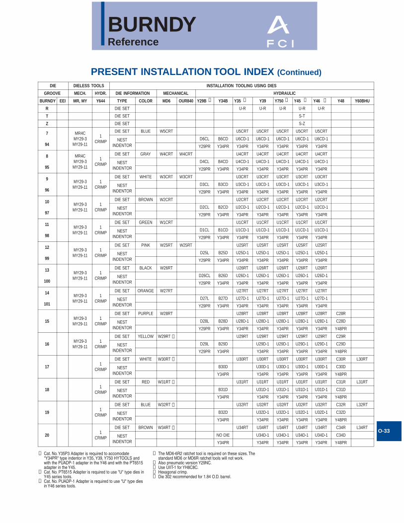
BURNDYReference
O-33
PRESENT INSTALLATION TOOL INDEX (Continued)
① Cat. No. Y35P3 Adapter is required to accomodate"Y34PR" type indentor in Y35, Y39, Y750 HYTOOLS andwith the PUADP-1 adapter in the Y46 and with the PT6515adapter in the Y45.
➁ Cat. No. PT6515 Adapter is required to use "U" type dies inY45 series tools.
③ Cat. No. PUADP-1 Adapter is required to use "U" type diesin Y46 series tools.
DIE DIELESS TOOLS INSTALLATION TOOLING USING DIES
GROOVE MECH. HYDR. DIE INFORMATION MECHANICAL HYDRAULIC
BURNDY EEI MR, MY Y644 TYPE COLOR MD6 OUR840 Y29B Y34B Y35 Y39 Y750 Y45 Y46 Y48 Y60BHU
R DIE SET U-R U-R U-R U-R U-R
T DIE SET S-T
Z DIE SET S-Z
7
94
MR4CMY29-3MY29-11
1CRIMP
DIE SET BLUE W5CRT U5CRT U5CRT U5CRT U5CRT U5CRT
NESTINDENTOR
D6CL B6CD U6CD-1 U6CD-1 U6CD-1 U6CD-1 U6CD-1
Y29PR Y34PR Y34PR Y34PR Y34PR Y34PR Y34PR
8
95
MR4CMY29-3MY29-11
1CRIMP
DIE SET GRAY W4CRT W4CRT U4CRT U4CRT U4CRT U4CRT U4CRT
NESTINDENTOR
D4CL B4CD U4CD-1 U4CD-1 U4CD-1 U4CD-1 U4CD-1
Y29PR Y34PR Y34PR Y34PR Y34PR Y34PR Y34PR
9
96
MY29-3MY29-11
1CRIMP
DIE SET WHITE W3CRT W3CRT U3CRT U3CRT U3CRT U3CRT U3CRT
NESTINDENTOR
D3CL B3CD U3CD-1 U3CD-1 U3CD-1 U3CD-1 U3CD-1
Y29PR Y34PR Y34PR Y34PR Y34PR Y34PR Y34PR
10
97
MY29-3MY29-11
1CRIMP
DIE SET BROWN W2CRT U2CRT U2CRT U2CRT U2CRT U2CRT
NESTINDENTOR
D2CL B2CD U2CD-1 U2CD-1 U2CD-1 U2CD-1 U2CD-1
Y29PR Y34PR Y34PR Y34PR Y34PR Y34PR Y34PR
11
98
MY29-3MY29-11
1CRIMP
DIE SET GREEN W1CRT U1CRT U1CRT U1CRT U1CRT U1CRT
NESTINDENTOR
D1CL B1CD U1CD-1 U1CD-1 U1CD-1 U1CD-1 U1CD-1
Y29PR Y34PR Y34PR Y34PR Y34PR Y34PR Y34PR
12
99
MY29-3MY29-11
1CRIMP
DIE SET PINK W25RT W25RT U25RT U25RT U25RT U25RT U25RT
NESTINDENTOR
D25L B25D U25D-1 U25D-1 U25D-1 U25D-1 U25D-1
Y29PR Y34PR Y34PR Y34PR Y34PR Y34PR Y34PR
13
100
MY29-3MY29-11
1CRIMP
DIE SET BLACK W26RT U26RT U26RT U26RT U26RT U26RT
NESTINDENTOR
D26CL B26D U26D-1 U26D-1 U26D-1 U26D-1 U26D-1
Y29PR Y34PR Y34PR Y34PR Y34PR Y34PR Y34PR
14
101
MY29-3MY29-11
1CRIMP
DIE SET ORANGE W27RT U27RT U27RT U27RT U27RT U27RT
NESTINDENTOR
D27L B27D U27D-1 U27D-1 U27D-1 U27D-1 U27D-1
Y29PR Y34PR Y34PR Y34PR Y34PR Y34PR Y34PR
15MY29-3MY29-11
1CRIMP
DIE SET PURPLE W28RT U28RT U28RT U28RT U28RT U28RT C28R
NESTINDENTOR
D28L B28D U28D-1 U28D-1 U28D-1 U28D-1 U28D-1 C28D
Y29PR Y34PR Y34PR Y34PR Y34PR Y34PR Y34PR Y48PR
16MY29-3MY29-11
1CRIMP
DIE SET YELLOW W29RT U29RT U29RT U29RT U29RT U29RT C29R
NESTINDENTOR
D29L B29D U29D-1 U29D-1 U29D-1 U29D-1 C29D
Y29PR Y34PR Y34PR Y34PR Y34PR Y34PR Y48PR
171
CRIMP
DIE SET WHITE W30RT U30RT U30RT U30RT U30RT U30RT C30R L30RT
NESTINDENTOR
B30D U30D-1 U30D-1 U30D-1 U30D-1 C30D
Y34PR Y34PR Y34PR Y34PR Y34PR Y48PR
181
CRIMP
DIE SET RED W31RT U31RT U31RT U31RT U31RT U31RT C31R L31RT
NESTINDENTOR
B31D U31D-1 U31D-1 U31D-1 U31D-1 C31D
Y34PR Y34PR Y34PR Y34PR Y34PR Y48PR
191
CRIMP
DIE SET BLUE W32RT U32RT U32RT U32RT U32RT U32RT C32R L32RT
NESTINDENTOR
B32D U32D-1 U32D-1 U32D-1 U32D-1 C32D
Y34PR Y34PR Y34PR Y34PR Y34PR Y48PR
201
CRIMP
DIE SET BROWN W34RT U34RT U34RT U34RT U34RT U34RT C34R L34RT
NESTINDENTOR
NO DIE U34D-1 U34D-1 U34D-1 U34D-1 C34D
Y34PR Y34PR Y34PR Y34PR Y34PR Y48PR
➄ ➀ ➀ ➁
➃
➃
➃
➃
➃
➂
➃ The MD6-6R2 ratchet tool is required on these sizes. Thestandard MD6 or MD6R ratchet tools will not work.
⑤ Also pneumatic version Y29NC.➅ Use UIIT-1 for YH8C8C.⑦ Hexagonal crimp.⑧ Die 302 recommended for 1.84 O.D. barrel.
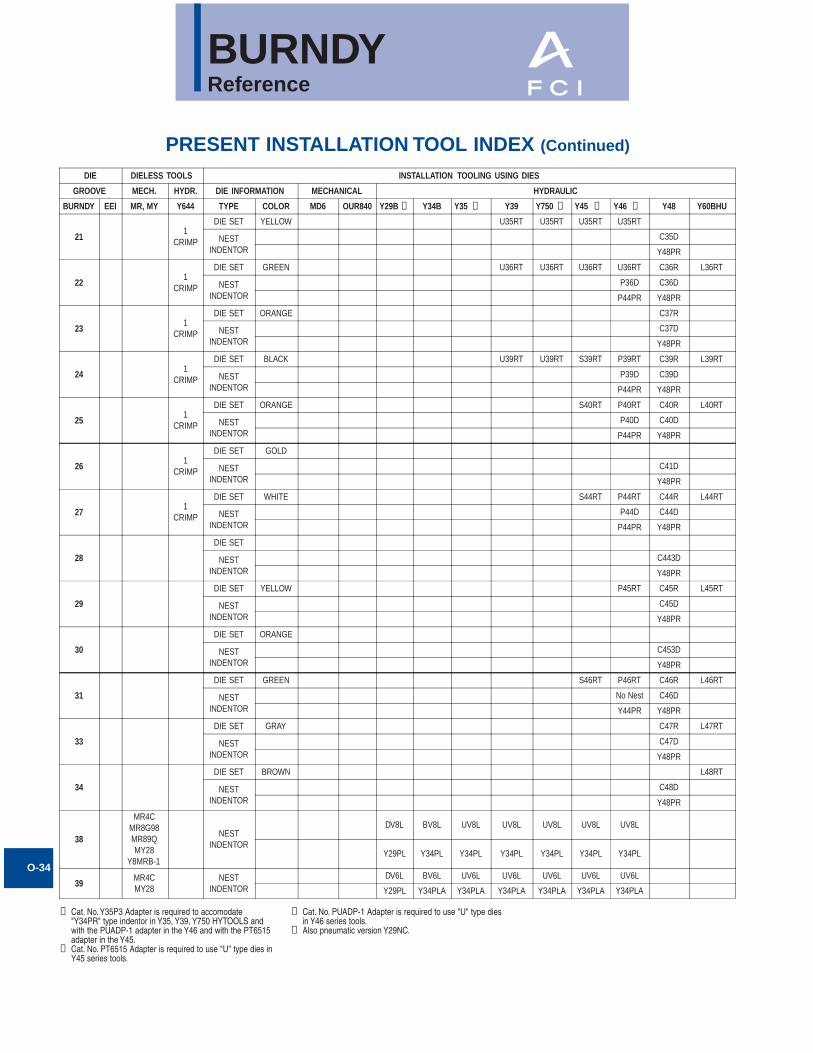
BURNDYReference
O-34
PRESENT INSTALLATION TOOL INDEX (Continued)
① Cat. No. Y35P3 Adapter is required to accomodate"Y34PR" type indentor in Y35, Y39, Y750 HYTOOLS andwith the PUADP-1 adapter in the Y46 and with the PT6515adapter in the Y45.
➁ Cat. No. PT6515 Adapter is required to use "U" type dies inY45 series tools.
DIE DIELESS TOOLS INSTALLATION TOOLING USING DIES
GROOVE MECH. HYDR. DIE INFORMATION MECHANICAL HYDRAULIC
BURNDY EEI MR, MY Y644 TYPE COLOR MD6 OUR840 Y29B Y34B Y35 Y39 Y750 Y45 Y46 Y48 Y60BHU
211
CRIMP
DIE SET YELLOW U35RT U35RT U35RT U35RT
NESTINDENTOR
C35D
Y48PR
221
CRIMP
DIE SET GREEN U36RT U36RT U36RT U36RT C36R L36RT
NESTINDENTOR
P36D C36D
P44PR Y48PR
231
CRIMP
DIE SET ORANGE C37R
NESTINDENTOR
C37D
Y48PR
241
CRIMP
DIE SET BLACK U39RT U39RT S39RT P39RT C39R L39RT
NESTINDENTOR
P39D C39D
P44PR Y48PR
251
CRIMP
DIE SET ORANGE S40RT P40RT C40R L40RT
NESTINDENTOR
P40D C40D
P44PR Y48PR
261
CRIMP
DIE SET GOLD
NESTINDENTOR
C41D
Y48PR
271
CRIMP
DIE SET WHITE S44RT P44RT C44R L44RT
NESTINDENTOR
P44D C44D
P44PR Y48PR
28
DIE SET
NESTINDENTOR
C443D
Y48PR
29
DIE SET YELLOW P45RT C45R L45RT
NESTINDENTOR
C45D
Y48PR
30
DIE SET ORANGE
NESTINDENTOR
C453D
Y48PR
31
DIE SET GREEN S46RT P46RT C46R L46RT
NESTINDENTOR
No Nest C46D
Y44PR Y48PR
33
DIE SET GRAY C47R L47RT
NESTINDENTOR
C47D
Y48PR
34
DIE SET BROWN L48RT
NESTINDENTOR
C48D
Y48PR
38
MR4CMR8G98MR89QMY28
Y8MRB-1
NESTINDENTOR
DV8L BV8L UV8L UV8L UV8L UV8L UV8L
Y29PL Y34PL Y34PL Y34PL Y34PL Y34PL Y34PL
39MR4CMY28
NESTINDENTOR
DV6L BV6L UV6L UV6L UV6L UV6L UV6L
Y29PL Y34PLA Y34PLA Y34PLA Y34PLA Y34PLA Y34PLA
➂➁➀ ➀➄
③ Cat. No. PUADP-1 Adapter is required to use "U" type diesin Y46 series tools.
⑤ Also pneumatic version Y29NC.
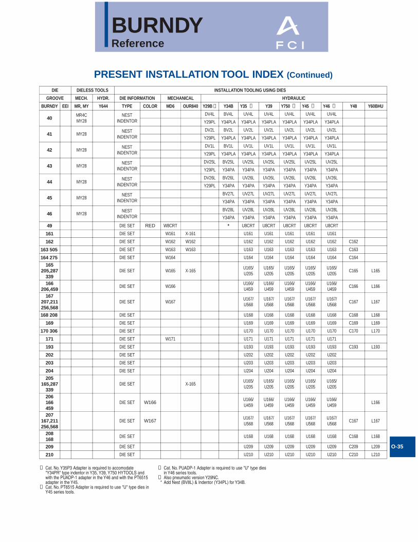
BURNDYReference
O-35
PRESENT INSTALLATION TOOL INDEX (Continued)
① Cat. No. Y35P3 Adapter is required to accomodate"Y34PR" type indentor in Y35, Y39, Y750 HYTOOLS andwith the PUADP-1 adapter in the Y46 and with the PT6515adapter in the Y45.
➁ Cat. No. PT6515 Adapter is required to use "U" type dies inY45 series tools.
DIE DIELESS TOOLS INSTALLATION TOOLING USING DIES
GROOVE MECH. HYDR. DIE INFORMATION MECHANICAL HYDRAULIC
BURNDY EEI MR, MY Y644 TYPE COLOR MD6 OUR840 Y29B Y34B Y35 Y39 Y750 Y45 Y46 Y48 Y60BHU
40MR4CMY28
NESTINDENTOR
DV4L BV4L UV4L UV4L UV4L UV4L UV4L
Y29PL Y34PLA Y34PLA Y34PLA Y34PLA Y34PLA Y34PLA
41 MY28NEST
INDENTORDV2L BV2L UV2L UV2L UV2L UV2L UV2L
Y29PL Y34PLA Y34PLA Y34PLA Y34PLA Y34PLA Y34PLA
42 MY28NEST
INDENTORDV1L BV1L UV1L UV1L UV1L UV1L UV1L
Y29PL Y34PLA Y34PLA Y34PLA Y34PLA Y34PLA Y34PLA
43 MY28NEST
INDENTORDV25L BV25L UV25L UV25L UV25L UV25L UV25L
Y29PL Y34PA Y34PA Y34PA Y34PA Y34PA Y34PA
44 MY28NEST
INDENTORDV26L BV26L UV26L UV26L UV26L UV26L UV26L
Y29PL Y34PA Y34PA Y34PA Y34PA Y34PA Y34PA
45 MY28NEST
INDENTORBV27L UV27L UV27L UV27L UV27L UV27L
Y34PA Y34PA Y34PA Y34PA Y34PA Y34PA
46 MY28NEST
INDENTORBV28L UV28L UV28L UV28L UV28L UV28L
Y34PA Y34PA Y34PA Y34PA Y34PA Y34PA
49 DIE SET RED W8CRT * U8CRT U8CRT U8CRT U8CRT U8CRT
161 DIE SET W161 X-161 U161 U161 U161 U161 U161
162 DIE SET W162 W162 U162 U162 U162 U162 U162 C162
163 505 DIE SET W163 W163 U163 U163 U163 U163 U163 C163
164 275 DIE SET W164 U164 U164 U164 U164 U164 C164
165205,287
339DIE SET W165 X-165
U165/U205
U165/U205
U165/U205
U165/U205
U165/U205
C165 L165
166206,459
DIE SET W166U166/U459
U166/U459
U166/U459
U166/U459
U166/U459
C166 L166
167207,211256,568
DIE SET W167U167/U568
U167/U568
U167/U568
U167/U568
U167/U568
C167 L167
168 208 DIE SET U168 U168 U168 U168 U168 C168 L168
169 DIE SET U169 U169 U169 U169 U169 C169 L169
170 306 DIE SET U170 U170 U170 U170 U170 C170 L170
171 DIE SET W171 U171 U171 U171 U171 U171
193 DIE SET U193 U193 U193 U193 U193 C193 L193
202 DIE SET U202 U202 U202 U202 U202
203 DIE SET U203 U203 U203 U203 U203
204 DIE SET U204 U204 U204 U204 U204
205165,287
339DIE SET X-165
U165/U205
U165/U205
U165/U205
U165/U205
U165/U205
206166459
DIE SET W166U166/U459
U166/U459
U166/U459
U166/U459
U166/U459
L166
207167,211256,568
DIE SET W167U167/U568
U167/U568
U167/U568
U167/U568
U167/U568
C167 L167
208168
DIE SET U168 U168 U168 U168 U168 C168 L168
209 DIE SET U209 U209 U209 U209 U209 C209 L209
210 DIE SET U210 U210 U210 U210 U210 C210 L210
➄ ➀ ➀ ➁ ➂
③ Cat. No. PUADP-1 Adapter is required to use "U" type diesin Y46 series tools.
⑤ Also pneumatic version Y29NC.* Add Nest (BV8L) & Indentor (Y34PL) for Y34B.
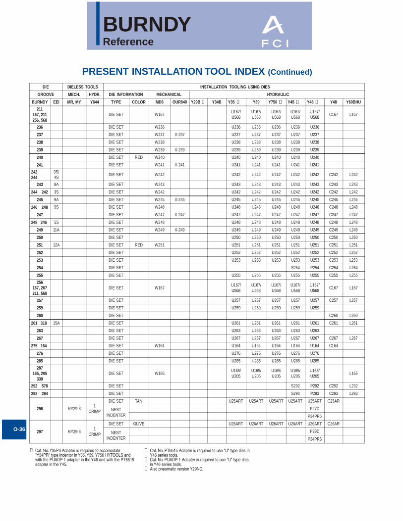
BURNDYReference
O-36
PRESENT INSTALLATION TOOL INDEX (Continued)
① Cat. No. Y35P3 Adapter is required to accomodate"Y34PR" type indentor in Y35, Y39, Y750 HYTOOLS andwith the PUADP-1 adapter in the Y46 and with the PT6515adapter in the Y45.
➀ ➁ ➂➀➄
DIE DIELESS TOOLS INSTALLATION TOOLING USING DIES
GROOVE MECH. HYDR. DIE INFORMATION MECHANICAL HYDRAULIC
BURNDY EEI MR, MY Y644 TYPE COLOR MD6 OUR840 Y29B Y34B Y35 Y39 Y750 Y45 Y46 Y48 Y60BHU
211167, 211256, 568
DIE SET W167U167/U568
U167/U568
U167/U568
U167/U568
U167/U568
C167 L167
236 DIE SET W236 U236 U236 U236 U236 U236
237 DIE SET W237 X-237 U237 U237 U237 U237 U237
238 DIE SET W238 U238 U238 U238 U238 U238
239 DIE SET W239 X-239 U239 U239 U239 U239 U239
240 DIE SET RED W240 U240 U240 U240 U240 U240
241 DIE SET W241 X-241 U241 U241 U241 U241 U241
242244
3S/4S
DIE SET W242 U242 U242 U242 U242 U242 C242 L242
243 8A DIE SET W243 U243 U243 U243 U243 U243 C243 L243
244 242 3S DIE SET W242 U242 U242 U242 U242 U242 C242 L242
245 9A DIE SET W245 X-245 U245 U245 U245 U245 U245 C245 L245
246 248 5S DIE SET W248 U248 U248 U248 U248 U248 C248 L248
247 DIE SET W247 X-247 U247 U247 U247 U247 U247 C247 L247
248 246 5S DIE SET W248 U248 U248 U248 U248 U248 C248 L248
249 11A DIE SET W249 X-249 U249 U249 U249 U249 U249 C249 L249
250 DIE SET U250 U250 U250 U250 U250 C250 L250
251 12A DIE SET RED W251 U251 U251 U251 U251 U251 C251 L251
252 DIE SET U252 U252 U252 U252 U252 C252 L252
253 DIE SET U253 U253 U253 U253 U253 C253 L253
254 DIE SET S254 P254 C254 L254
255 DIE SET U255 U255 U255 U255 U255 C255 L255
256167, 207211, 568
DIE SET W167U167/U568
U167/U568
U167/U568
U167/U568
U167/U568
C167 L167
257 DIE SET U257 U257 U257 U257 U257 C257 L257
259 DIE SET U259 U259 U259 U259 U259
260 DIE SET C260 L260
261 318 15A DIE SET U261 U261 U261 U261 U261 C261 L261
263 DIE SET U263 U263 U263 U263 U263
267 DIE SET U267 U267 U267 U267 U267 C267 L267
275 164 DIE SET W164 U164 U164 U164 U164 U164 C164
276 DIE SET U276 U276 U276 U276 U276
285 DIE SET U285 U285 U285 U285 U285
287165, 205
339DIE SET W165
U165/U205
U165/U205
U165/U205
U165/U205
U165/U205
L165
292 578 DIE SET S292 P292 C292 L292
293 294 DIE SET S293 P293 C293 L293
296 MY29-31
CRIMP
DIE SET TAN U25ART U25ART U25ART U25ART U25ART C25AR
NESTINDENTER
P27D
P34PR5
297 MY29-31
CRIMP
DIE SET OLIVE U26ART U26ART U26ART U26ART U26ART C26AR
NESTINDENTER
P29D
P34PR5
➁ Cat. No. PT6515 Adapter is required to use "U" type dies inY45 series tools.
③ Cat. No. PUADP-1 Adapter is required to use "U" type diesin Y46 series tools.
⑤ Also pneumatic version Y29NC.
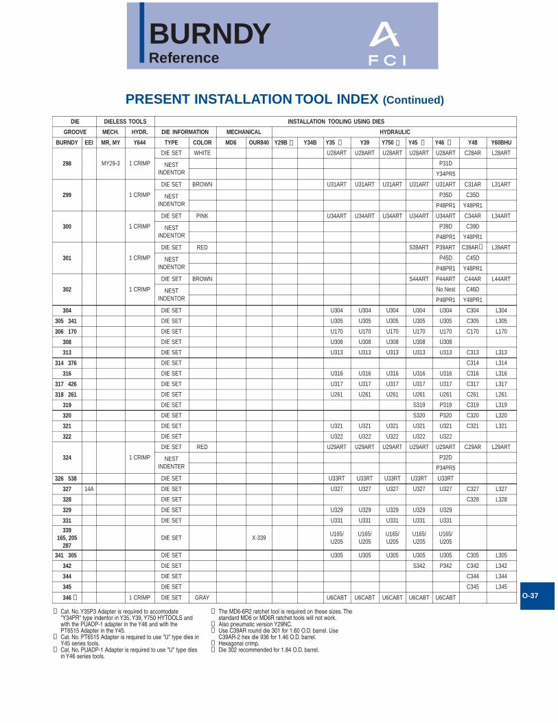
BURNDYReference
O-37
PRESENT INSTALLATION TOOL INDEX (Continued)
① Cat. No. Y35P3 Adapter is required to accomodate"Y34PR" type indentor in Y35, Y39, Y750 HYTOOLS andwith the PUADP-1 adapter in the Y46 and with thePT6515 Adapter in the Y45.
➁ Cat. No. PT6515 Adapter is required to use "U" type dies inY45 series tools.
③ Cat. No. PUADP-1 Adapter is required to use "U" type diesin Y46 series tools.
DIE DIELESS TOOLS INSTALLATION TOOLING USING DIES
GROOVE MECH. HYDR. DIE INFORMATION MECHANICAL HYDRAULIC
BURNDY EEI MR, MY Y644 TYPE COLOR MD6 OUR840 Y29B Y34B Y35 Y39 Y750 Y45 Y46 Y48 Y60BHU
298 MY29-3 1 CRIMP
DIE SET WHITE U28ART U28ART U28ART U28ART U28ART C28AR L28ART
NESTINDENTOR
P31D
Y34PR5
299 1 CRIMP
DIE SET BROWN U31ART U31ART U31ART U31ART U31ART C31AR L31ART
NESTINDENTOR
P35D C35D
P48PR1 Y48PR1
300 1 CRIMP
DIE SET PINK U34ART U34ART U34ART U34ART U34ART C34AR L34ART
NESTINDENTOR
P39D C39D
P48PR1 Y48PR1
301 1 CRIMP
DIE SET RED S39ART P39ART C39AR L39ART
NESTINDENTOR
P45D C45D
P48PR1 Y48PR1
302 1 CRIMP
DIE SET BROWN S44ART P44ART C44AR L44ART
NESTINDENTOR
No Nest C46D
P48PR1 Y48PR1
304 DIE SET U304 U304 U304 U304 U304 C304 L304
305 341 DIE SET U305 U305 U305 U305 U305 C305 L305
306 170 DIE SET U170 U170 U170 U170 U170 C170 L170
308 DIE SET U308 U308 U308 U308 U308
313 DIE SET U313 U313 U313 U313 U313 C313 L313
314 376 DIE SET C314 L314
316 DIE SET U316 U316 U316 U316 U316 C316 L316
317 426 DIE SET U317 U317 U317 U317 U317 C317 L317
318 261 DIE SET U261 U261 U261 U261 U261 C261 L261
319 DIE SET S319 P319 C319 L319
320 DIE SET S320 P320 C320 L320
321 DIE SET U321 U321 U321 U321 U321 C321 L321
322 DIE SET U322 U322 U322 U322 U322
324 1 CRIMP
DIE SET RED U29ART U29ART U29ART U29ART U29ART C29AR L29ART
NESTINDENTER
P32D
P34PR5
326 538 DIE SET U33RT U33RT U33RT U33RT U33RT
327 14A DIE SET U327 U327 U327 U327 U327 C327 L327
328 DIE SET C328 L328
329 DIE SET U329 U329 U329 U329 U329
331 DIE SET U331 U331 U331 U331 U331
339165, 205
287DIE SET X-339
U165/U205
U165/U205
U165/U205
U165/U205
U165/U205
341 305 DIE SET U305 U305 U305 U305 U305 C305 L305
342 DIE SET S342 P342 C342 L342
344 DIE SET C344 L344
345 DIE SET C345 L345
346 1 CRIMP DIE SET GRAY U6CABT U6CABT U6CABT U6CABT U6CABT➆
➀➀ ➁ ➂
➅
➄
➃ The MD6-6R2 ratchet tool is required on these sizes. Thestandard MD6 or MD6R ratchet tools will not work.
⑤ Also pneumatic version Y29NC.➅ Use C39AR round die 301 for 1.60 O.D. barrel. Use
C39AR-2 hex die 936 for 1.46 O.D. barrel.⑦ Hexagonal crimp.⑧ Die 302 recommended for 1.84 O.D. barrel.
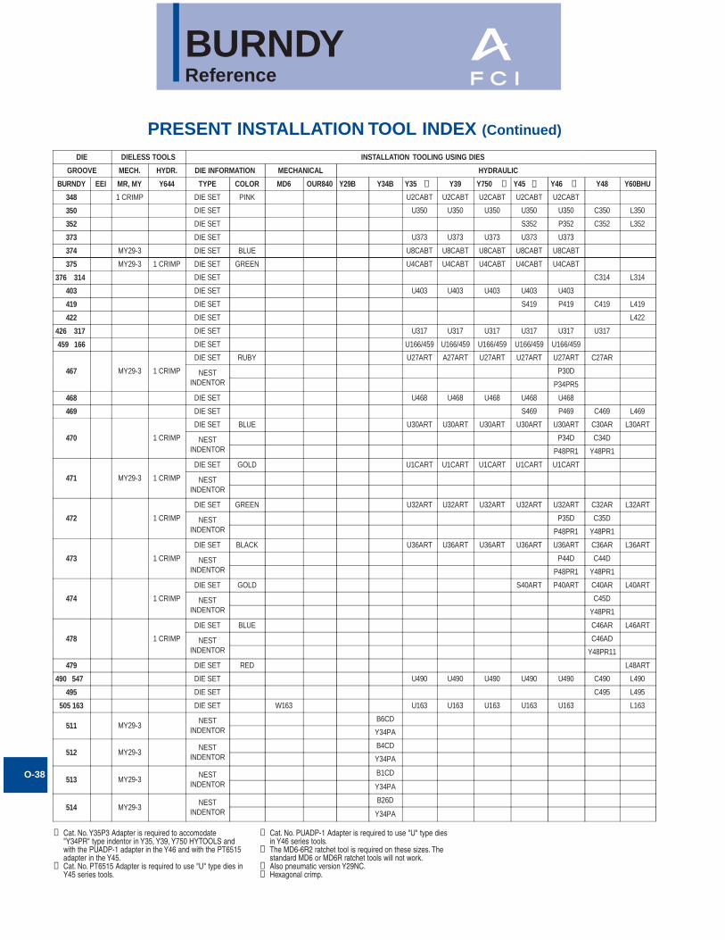
BURNDYReference
O-38
PRESENT INSTALLATION TOOL INDEX (Continued)
① Cat. No. Y35P3 Adapter is required to accomodate"Y34PR" type indentor in Y35, Y39, Y750 HYTOOLS andwith the PUADP-1 adapter in the Y46 and with the PT6515adapter in the Y45.
➁ Cat. No. PT6515 Adapter is required to use "U" type dies inY45 series tools.
DIE DIELESS TOOLS INSTALLATION TOOLING USING DIES
GROOVE MECH. HYDR. DIE INFORMATION MECHANICAL HYDRAULIC
BURNDY EEI MR, MY Y644 TYPE COLOR MD6 OUR840 Y29B Y34B Y35 Y39 Y750 Y45 Y46 Y48 Y60BHU
348 1 CRIMP DIE SET PINK U2CABT U2CABT U2CABT U2CABT U2CABT
350 DIE SET U350 U350 U350 U350 U350 C350 L350
352 DIE SET S352 P352 C352 L352
373 DIE SET U373 U373 U373 U373 U373
374 MY29-3 DIE SET BLUE U8CABT U8CABT U8CABT U8CABT U8CABT
375 MY29-3 1 CRIMP DIE SET GREEN U4CABT U4CABT U4CABT U4CABT U4CABT
376 314 DIE SET C314 L314
403 DIE SET U403 U403 U403 U403 U403
419 DIE SET S419 P419 C419 L419
422 DIE SET L422
426 317 DIE SET U317 U317 U317 U317 U317 U317
459 166 DIE SET U166/459 U166/459 U166/459 U166/459 U166/459
467 MY29-3 1 CRIMP
DIE SET RUBY U27ART A27ART U27ART U27ART U27ART C27AR
NESTINDENTOR
P30D
P34PR5
468 DIE SET U468 U468 U468 U468 U468
469 DIE SET S469 P469 C469 L469
470 1 CRIMP
DIE SET BLUE U30ART U30ART U30ART U30ART U30ART C30AR L30ART
NESTINDENTOR
P34D C34D
P48PR1 Y48PR1
471 MY29-3 1 CRIMP
DIE SET GOLD U1CART U1CART U1CART U1CART U1CART
NESTINDENTOR
472 1 CRIMP
DIE SET GREEN U32ART U32ART U32ART U32ART U32ART C32AR L32ART
NESTINDENTOR
P35D C35D
P48PR1 Y48PR1
473 1 CRIMP
DIE SET BLACK U36ART U36ART U36ART U36ART U36ART C36AR L36ART
NESTINDENTOR
P44D C44D
P48PR1 Y48PR1
474 1 CRIMP
DIE SET GOLD S40ART P40ART C40AR L40ART
NESTINDENTOR
C45D
Y48PR1
478 1 CRIMP
DIE SET BLUE C46AR L46ART
NESTINDENTOR
C46AD
Y48PR11
479 DIE SET RED L48ART
490 547 DIE SET U490 U490 U490 U490 U490 C490 L490
495 DIE SET C495 L495
505 163 DIE SET W163 U163 U163 U163 U163 U163 L163
511 MY29-3NEST
INDENTORB6CD
Y34PA
512 MY29-3NEST
INDENTORB4CD
Y34PA
513 MY29-3NEST
INDENTORB1CD
Y34PA
514 MY29-3NEST
INDENTOR
B26D
Y34PA
➀ ➀ ➁ ➂
③ Cat. No. PUADP-1 Adapter is required to use "U" type diesin Y46 series tools.
➃ The MD6-6R2 ratchet tool is required on these sizes. Thestandard MD6 or MD6R ratchet tools will not work.
⑤ Also pneumatic version Y29NC.➅ Hexagonal crimp.
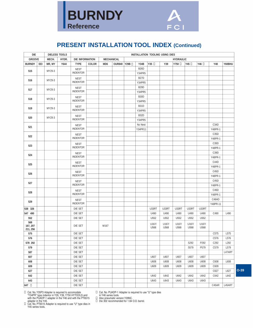
BURNDYReference
O-39
PRESENT INSTALLATION TOOL INDEX (Continued)
① Cat. No. Y35P3 Adapter is required to accomodate"Y34PR" type indentor in Y35, Y39, Y750 HYTOOLS andwith the PUADP-1 adapter in the Y46 and with the PT6515adapter in the Y45.
➁ Cat. No. PT6515 Adapter is required to use "U" type dies inY45 series tools.
DIE DIELESS TOOLS INSTALLATION TOOLING USING DIES
GROOVE MECH. HYDR. DIE INFORMATION MECHANICAL HYDRAULIC
BURNDY EEI MR, MY Y644 TYPE COLOR MD6 OUR840 Y29B Y34B Y35 Y39 Y750 Y45 Y46 Y48 Y60BHU
515 MY29-3NEST
INDENTORB26D
Y34PR5
516 MY29-3NEST
INDENTORB27D
Y34PR5
517 MY29-3NEST
INDENTORB29D
Y34PR5
518 MY29-3NEST
INDENTORB30D
Y34PR5
519 MY29-3NEST
INDENTORB31D
Y34PR5
520 MY29-3NEST
INDENTORB32D
Y34PR5
521NEST
INDENTORNo Nest C34D
Y34PR11 Y48PR-1
522NEST
INDENTORC35D
Y48PR-1
523NEST
INDENTORC35D
Y48PR-1
524NEST
INDENTORC39D
Y48PR-1
525NEST
INDENTORC44D
Y48PR-1
526NEST
INDENTORC45D
Y48PR-1
527NEST
INDENTORC45D
Y48PR-1
528NEST
INDENTORC46D
Y48PR-1
529NEST
INDENTORC46AD
Y48PR-11
538 326 DIE SET U33RT U33RT U33RT U33RT U33RT
547 490 DIE SET U490 U490 U490 U490 U490 C490 L490
552 DIE SET U552 U552 U552 U552 U552
568167, 207211, 256
DIE SET W167U167/U568
U167/U568
U167/U568
U167/U568
U167/U568
575 DIE SET C575 L575
576 DIE SET C576 L576
578 292 DIE SET S292 P292 C292 L292
579 DIE SET S579 P579 C579 L579
587 DIE SET L47ART
607 DIE SET U607 U607 U607 U607 U607
608 DIE SET U608 U608 U608 U608 U608 C608 L608
609 DIE SET U609 U609 U609 U609 U609 C609
627 DIE SET C627 L627
642 DIE SET U642 U642 U642 U642 U642 C642 L642
643 DIE SET U643 U643 U643 U643 U643
647 DIE SET C45AR L45ART⑤
➀ ➀ ➁ ➂➄
③ Cat. No. PUADP-1 Adapter is required to use "U" type diesin Y46 series tools.
➃ Also pneumatic version Y29NC.⑤ Die 302 recommended for 1.84 O.D. barrel.
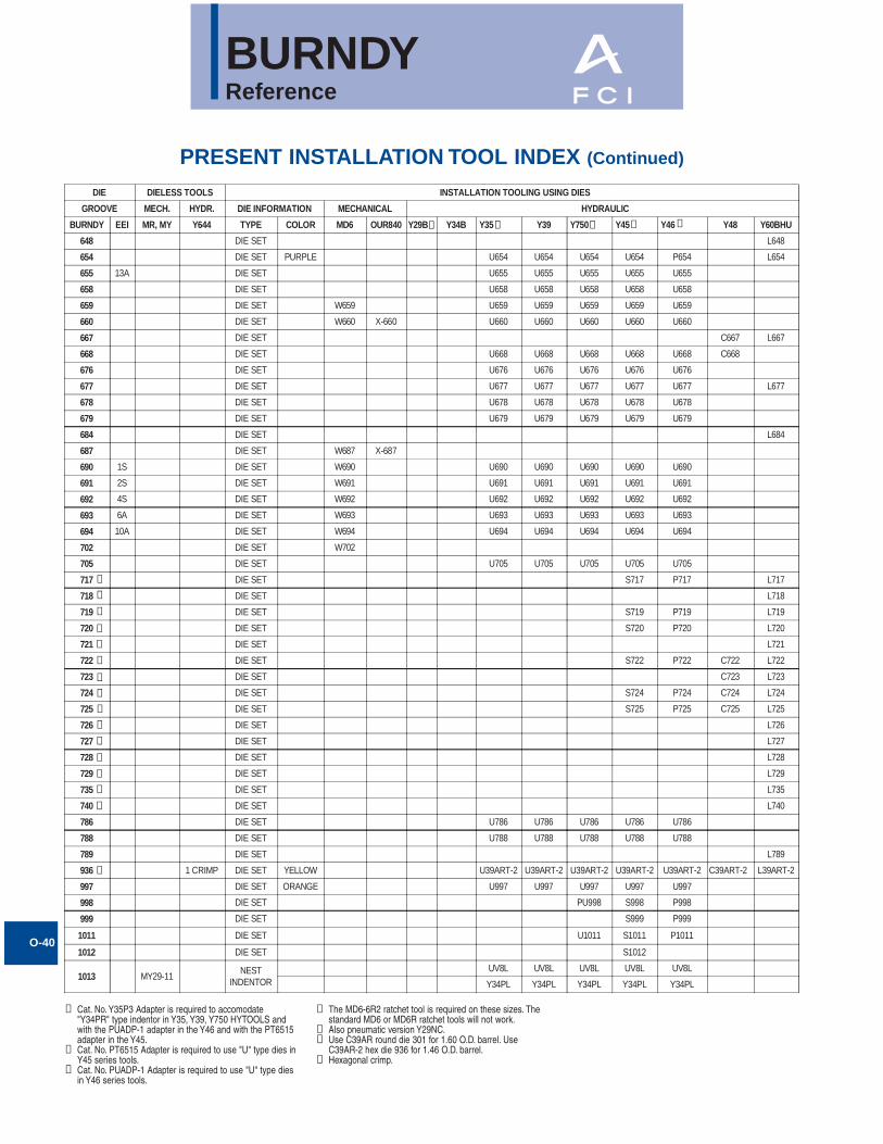
BURNDYReference
O-40
PRESENT INSTALLATION TOOL INDEX (Continued)
① Cat. No. Y35P3 Adapter is required to accomodate"Y34PR" type indentor in Y35, Y39, Y750 HYTOOLS andwith the PUADP-1 adapter in the Y46 and with the PT6515adapter in the Y45.
➁ Cat. No. PT6515 Adapter is required to use "U" type dies inY45 series tools.
③ Cat. No. PUADP-1 Adapter is required to use "U" type diesin Y46 series tools.
DIE DIELESS TOOLS INSTALLATION TOOLING USING DIES
GROOVE MECH. HYDR. DIE INFORMATION MECHANICAL HYDRAULIC
BURNDY EEI MR, MY Y644 TYPE COLOR MD6 OUR840 Y29B Y34B Y35 Y39 Y750 Y45 Y46 Y48 Y60BHU
648 DIE SET L648
654 DIE SET PURPLE U654 U654 U654 U654 P654 L654
655 13A DIE SET U655 U655 U655 U655 U655
658 DIE SET U658 U658 U658 U658 U658
659 DIE SET W659 U659 U659 U659 U659 U659
660 DIE SET W660 X-660 U660 U660 U660 U660 U660
667 DIE SET C667 L667
668 DIE SET U668 U668 U668 U668 U668 C668
676 DIE SET U676 U676 U676 U676 U676
677 DIE SET U677 U677 U677 U677 U677 L677
678 DIE SET U678 U678 U678 U678 U678
679 DIE SET U679 U679 U679 U679 U679
684 DIE SET L684
687 DIE SET W687 X-687
690 1S DIE SET W690 U690 U690 U690 U690 U690
691 2S DIE SET W691 U691 U691 U691 U691 U691
692 4S DIE SET W692 U692 U692 U692 U692 U692
693 6A DIE SET W693 U693 U693 U693 U693 U693
694 10A DIE SET W694 U694 U694 U694 U694 U694
702 DIE SET W702
705 DIE SET U705 U705 U705 U705 U705
717 DIE SET S717 P717 L717
718 DIE SET L718
719 DIE SET S719 P719 L719
720 DIE SET S720 P720 L720
721 DIE SET L721
722 DIE SET S722 P722 C722 L722
723 DIE SET C723 L723
724 DIE SET S724 P724 C724 L724
725 DIE SET S725 P725 C725 L725
726 DIE SET L726
727 DIE SET L727
728 DIE SET L728
729 DIE SET L729
735 DIE SET L735
740 DIE SET L740
786 DIE SET U786 U786 U786 U786 U786
788 DIE SET U788 U788 U788 U788 U788
789 DIE SET L789
936 1 CRIMP DIE SET YELLOW U39ART-2 U39ART-2 U39ART-2 U39ART-2 U39ART-2 C39ART-2 L39ART-2
997 DIE SET ORANGE U997 U997 U997 U997 U997
998 DIE SET PU998 S998 P998
999 DIE SET S999 P999
1011 DIE SET U1011 S1011 P1011
1012 DIE SET S1012
1013 MY29-11NEST
INDENTORUV8L UV8L UV8L UV8L UV8L
Y34PL Y34PL Y34PL Y34PL Y34PL
➄ ➀ ➀ ➁ ➂
➆
➆
➆
➆
➆
➆
➆
➆
➆
➆
➆
➆
➆
➆
➆
➆
➃ The MD6-6R2 ratchet tool is required on these sizes. Thestandard MD6 or MD6R ratchet tools will not work.
⑤ Also pneumatic version Y29NC.➅ Use C39AR round die 301 for 1.60 O.D. barrel. Use
C39AR-2 hex die 936 for 1.46 O.D. barrel.⑦ Hexagonal crimp.
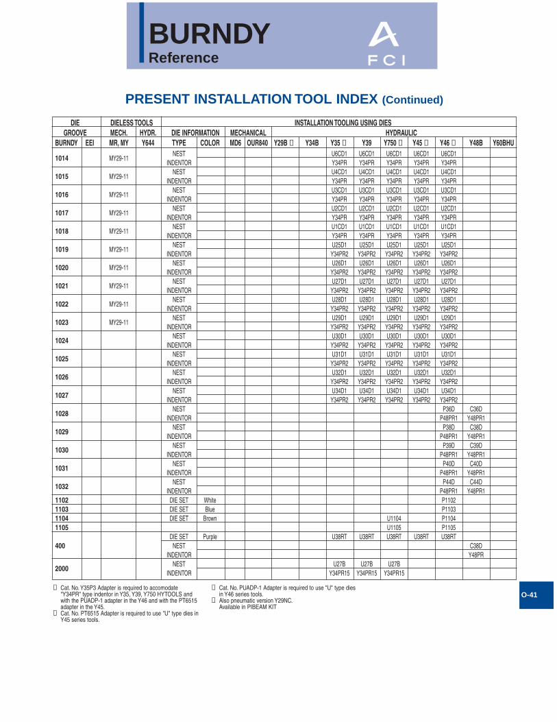
BURNDYReference
O-41
PRESENT INSTALLATION TOOL INDEX (Continued)
➀ Cat. No. Y35P3 Adapter is required to accomodate"Y34PR" type indentor in Y35, Y39, Y750 HYTOOLS andwith the PUADP-1 adapter in the Y46 and with the PT6515adapter in the Y45.
➁ Cat. No. PT6515 Adapter is required to use "U" type dies inY45 series tools.
DIE DIELESS TOOLS INSTALLATION TOOLING USING DIESGROOVE MECH. HYDR. DIE INFORMATION MECHANICAL HYDRAULIC
BURNDY EEI MR, MY Y644 TYPE COLOR MD6 OUR840 Y29B ➃ Y34B Y35 ➀ Y39 Y750 ➀ Y45 ➁ Y46 ➂ Y48B Y60BHUNEST U6CD1 U6CD1 U6CD1 U6CD1 U6CD1
1014 MY29-11INDENTOR Y34PR Y34PR Y34PR Y34PR Y34PR
NEST U4CD1 U4CD1 U4CD1 U4CD1 U4CD11015 MY29-11
INDENTOR Y34PR Y34PR Y34PR Y34PR Y34PRNEST U3CD1 U3CD1 U3CD1 U3CD1 U3CD1
1016 MY29-11INDENTOR Y34PR Y34PR Y34PR Y34PR Y34PR
NEST U2CD1 U2CD1 U2CD1 U2CD1 U2CD11017 MY29-11
INDENTOR Y34PR Y34PR Y34PR Y34PR Y34PRNEST U1CD1 U1CD1 U1CD1 U1CD1 U1CD1
1018 MY29-11INDENTOR Y34PR Y34PR Y34PR Y34PR Y34PR
NEST U25D1 U25D1 U25D1 U25D1 U25D11019 MY29-11
INDENTOR Y34PR2 Y34PR2 Y34PR2 Y34PR2 Y34PR2NEST U26D1 U26D1 U26D1 U26D1 U26D1
1020 MY29-11INDENTOR Y34PR2 Y34PR2 Y34PR2 Y34PR2 Y34PR2
NEST U27D1 U27D1 U27D1 U27D1 U27D11021 MY29-11
INDENTOR Y34PR2 Y34PR2 Y34PR2 Y34PR2 Y34PR2NEST U28D1 U28D1 U28D1 U28D1 U28D1
1022 MY29-11INDENTOR Y34PR2 Y34PR2 Y34PR2 Y34PR2 Y34PR2
NEST U29D1 U29D1 U29D1 U29D1 U29D11023 MY29-11
INDENTOR Y34PR2 Y34PR2 Y34PR2 Y34PR2 Y34PR2NEST U30D1 U30D1 U30D1 U30D1 U30D1
1024INDENTOR Y34PR2 Y34PR2 Y34PR2 Y34PR2 Y34PR2
NEST U31D1 U31D1 U31D1 U31D1 U31D11025
INDENTOR Y34PR2 Y34PR2 Y34PR2 Y34PR2 Y34PR2NEST U32D1 U32D1 U32D1 U32D1 U32D1
1026INDENTOR Y34PR2 Y34PR2 Y34PR2 Y34PR2 Y34PR2
NEST U34D1 U34D1 U34D1 U34D1 U34D11027
INDENTOR Y34PR2 Y34PR2 Y34PR2 Y34PR2 Y34PR2NEST P36D C36D
1028INDENTOR P48PR1 Y48PR1
NEST P38D C38D1029
INDENTOR P48PR1 Y48PR1NEST P39D C39D
1030INDENTOR P48PR1 Y48PR1
NEST P40D C40D1031
INDENTOR P48PR1 Y48PR1NEST P44D C44D
1032INDENTOR P48PR1 Y48PR1
1102 DIE SET White P11021103 DIE SET Blue P11031104 DIE SET Brown U1104 P11041105 U1105 P1105
DIE SET Purple U38RT U38RT U38RT U38RT U38RT400 NEST C38D
INDENTOR Y48PRNEST U27B U27B U27B
2000INDENTOR Y34PR15 Y34PR15 Y34PR15
➂ Cat. No. PUADP-1 Adapter is required to use "U" type diesin Y46 series tools.
➃ Also pneumatic version Y29NC.Available in PIBEAM KIT
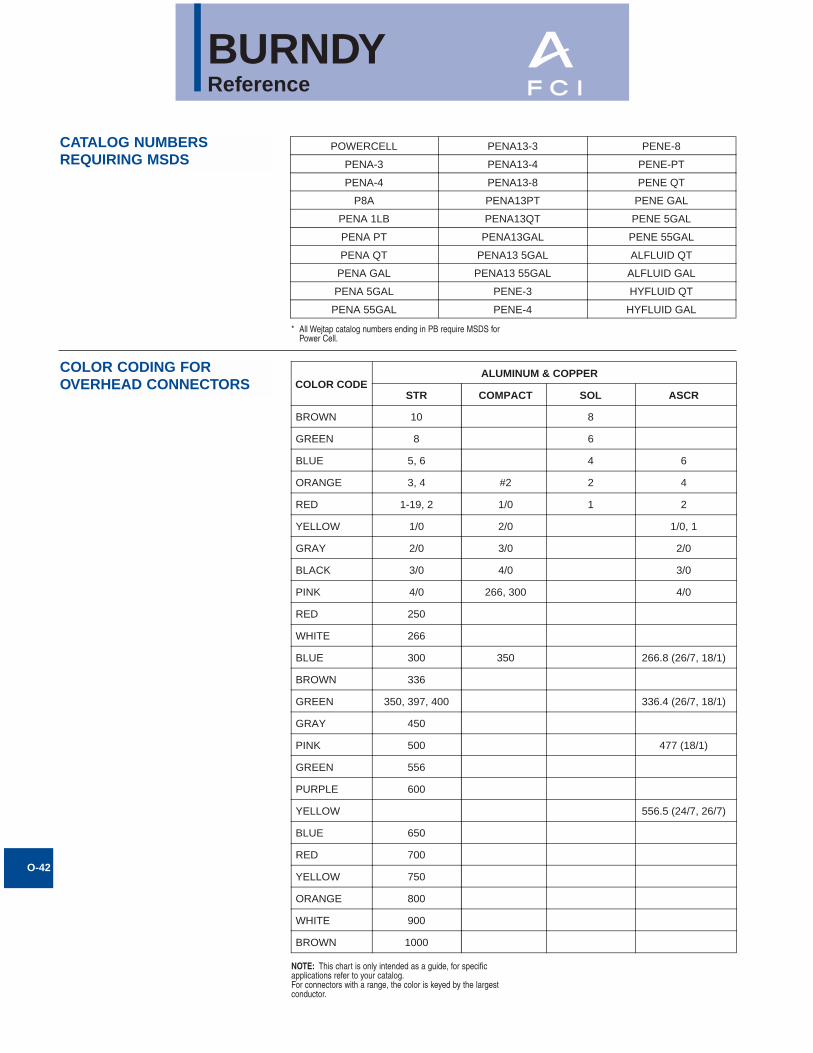
BURNDYReference
CATALOG NUMBERSREQUIRING MSDS
COLOR CODING FOR OVERHEAD CONNECTORS
O-42
POWERCELL PENA13-3 PENE-8
PENA-3 PENA13-4 PENE-PT
PENA-4 PENA13-8 PENE QT
P8A PENA13PT PENE GAL
PENA 1LB PENA13QT PENE 5GAL
PENA PT PENA13GAL PENE 55GAL
PENA QT PENA13 5GAL ALFLUID QT
PENA GAL PENA13 55GAL ALFLUID GAL
PENA 5GAL PENE-3 HYFLUID QT
PENA 55GAL PENE-4 HYFLUID GAL
COLOR CODEALUMINUM & COPPER
STR COMPACT SOL ASCR
BROWN 10 8
GREEN 8 6
BLUE 5, 6 4 6
ORANGE 3, 4 #2 2 4
RED 1-19, 2 1/0 1 2
YELLOW 1/0 2/0 1/0, 1
GRAY 2/0 3/0 2/0
BLACK 3/0 4/0 3/0
PINK 4/0 266, 300 4/0
RED 250
WHITE 266
BLUE 300 350 266.8 (26/7, 18/1)
BROWN 336
GREEN 350, 397, 400 336.4 (26/7, 18/1)
GRAY 450
PINK 500 477 (18/1)
GREEN 556
PURPLE 600
YELLOW 556.5 (24/7, 26/7)
BLUE 650
RED 700
YELLOW 750
ORANGE 800
WHITE 900
BROWN 1000
* All Wejtap catalog numbers ending in PB require MSDS forPower Cell.
NOTE: This chart is only intended as a guide, for specificapplications refer to your catalog.For connectors with a range, the color is keyed by the largestconductor.
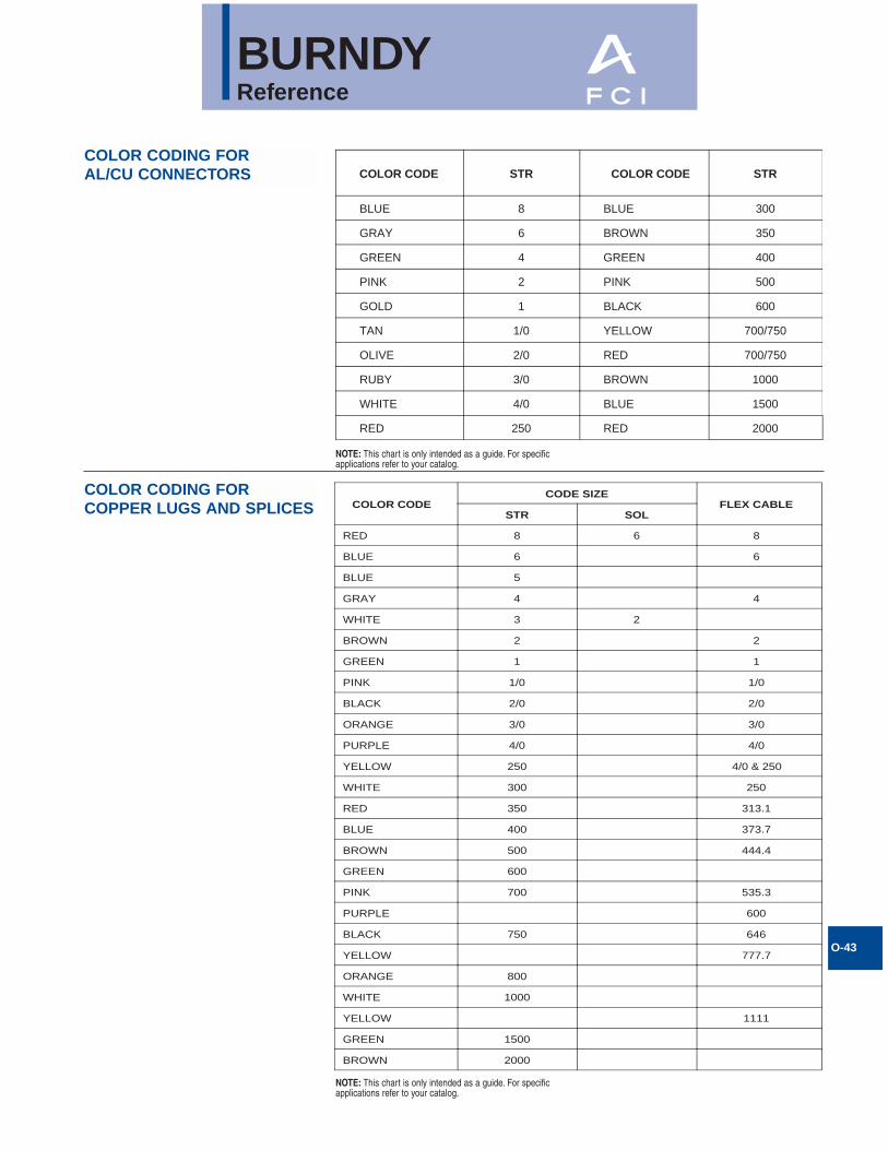
BURNDYReference
O-43
COLOR CODING FOR AL/CU CONNECTORS
COLOR CODING FOR COPPER LUGS AND SPLICES
COLOR CODE STR COLOR CODE STR
BLUE 8 BLUE 300
GRAY 6 BROWN 350
GREEN 4 GREEN 400
PINK 2 PINK 500
GOLD 1 BLACK 600
TAN 1/0 YELLOW 700/750
OLIVE 2/0 RED 700/750
RUBY 3/0 BROWN 1000
WHITE 4/0 BLUE 1500
RED 250 RED 2000
COLOR CODECODE SIZE
FLEX CABLESTR SOL
RED 8 6 8
BLUE 6 6
BLUE 5
GRAY 4 4
WHITE 3 2
BROWN 2 2
GREEN 1 1
PINK 1/0 1/0
BLACK 2/0 2/0
ORANGE 3/0 3/0
PURPLE 4/0 4/0
YELLOW 250 4/0 & 250
WHITE 300 250
RED 350 313.1
BLUE 400 373.7
BROWN 500 444.4
GREEN 600
PINK 700 535.3
PURPLE 600
BLACK 750 646
YELLOW 777.7
ORANGE 800
WHITE 1000
YELLOW 1111
GREEN 1500
BROWN 2000
NOTE: This chart is only intended as a guide. For specificapplications refer to your catalog.
NOTE: This chart is only intended as a guide. For specificapplications refer to your catalog.