bullflex(r) support system - dsi underground
TRANSCRIPT

BULLFLEX® Support System
Powerful in Action

2

ContentsSystem Solutions 4
Introduction 4
System Description 6
Main Advantages 6
System Components 8
Specifications 9
Material Logistics, Pumping, and Mixing Equipment 10
Support Pillars 11
Standard Dimensions 11
Characteristics 11
Installation Procedure 12
Load-Bearing Capacity 13
Roof Support Backfilling 14
Standard Dimensions 14
Transformation Point-Load to Full-Surface Support Action 14
Installation Procedure 15
Tunneling 16
Mining 16
Special Solutions 17
Technical Barriers – Tunnel Plugs for Flooded Underground Structures 17
Installation Procedure 17
Artificial Pillars 18
Mine Rehabilitation – Safekeeping Measures 18
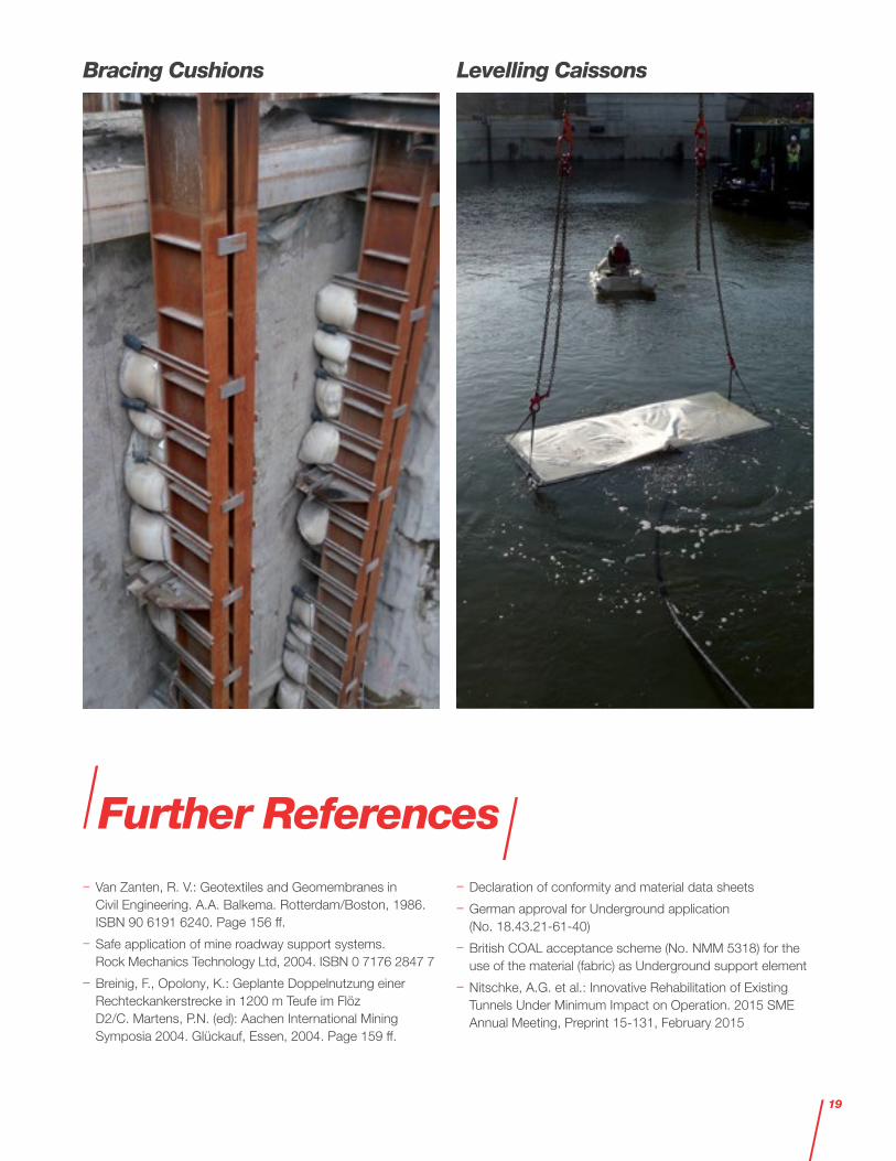
Bracing Cushions 19
Levelling Caissons 19
Further References 19
3

Introduction
The BULLFLEX® support system has been developed as a special supporting member for underground Mining and Tunneling. It consists of patented textile groutable hoses made of high-strength fabric, which are subsequently filled with cement-bonded construction material, featuring a supreme load-bearing capacity.
The BULLFLEX® support system is available for different applications and in different dimensions, allowing an optimum alignment to respective excavation and support requirements. All system components are lightweight and easy to transport and to install.
DSI Underground has long-time experience in the application of the BULLFLEX® support system, which has been successfully used for various projects.
Hard Rock Mining Soft Rock MiningMine
RehabilitationTunnel
RehabilitationTBM’s and
Foundations
Support pillars
Auxiliary standing support, artificial pillars, and
cornerslumps
Secondary support in room & pillar and
longwall mining
Repair works in overstressed or fault zone areas and rehabilitation of visitor mines
Roof support backfilling and underpinning
Backfilling of steel support for
permanent main roadways
Yielding support system –
displacement minimization
Re-establishment of the load-bearing
capacity and yielding ability of destructed
tunnel linings
Foundation and prestressing of pipe umbrella support or rib support systems
Temporary steel frame support for
the construction of cross-cuts
Roadway packs and
dams
Multiple entry roadways, gaseous seams, and deep mining operations
Structural bulkheads
Sealing against backfilling media
Permanent sealing of roadways
Partition of storage or waste facilities
StoppingsVentilation walls, sealings,
and face shuttering
Structural sealings 1)
Sealing of existing re-lined tunnels and annular gaps of civil
structures
O-ring sealings: launch and
receptions of TBM’s, sealing against water
(liquids) and compressed air
1) See separate section BULLFLEX® structural sealings.
System Solutions
4
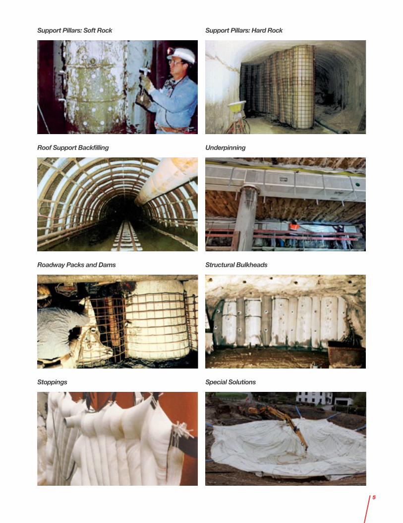
Roadway Packs and Dams
Support Pillars: Soft Rock Support Pillars: Hard Rock
Structural Bulkheads
Underpinning
Stoppings
Roof Support Backfilling
Special Solutions
5

Main Advantages
– Fast and safe support system
– Immediate high load-bearing capacity and load transfer
– Active setting load and controlled residual load
– Flexible support characteristics thanks to different variations of groutable hose diameter and filling media
– Defined consumption of filling material
– Inflation can be achieved using different types of filling material
– Shrink-free
– Quick and easy to install
– Easy handling on-site due to lightweight components
– Application possible even in limited space conditions
The BULLFLEX® support system is used wherever a fast support solution is required. Due to active setting load and immediate load transfer, BULLFLEX® groutable hoses work like a strong hydraulic prop or competent bedding
layer, which can be left in position as a permanent support.
BULLFLEX® groutable hoses are shrink-free because of their patented encasement – woven fabric hoses made of high-strength fabric.
Depending on the required load and geometry, the BULLFLEX® support system can easily be adapted to on-site conditions using different diameters or filling material with varying compressive strengths.
System Description
6
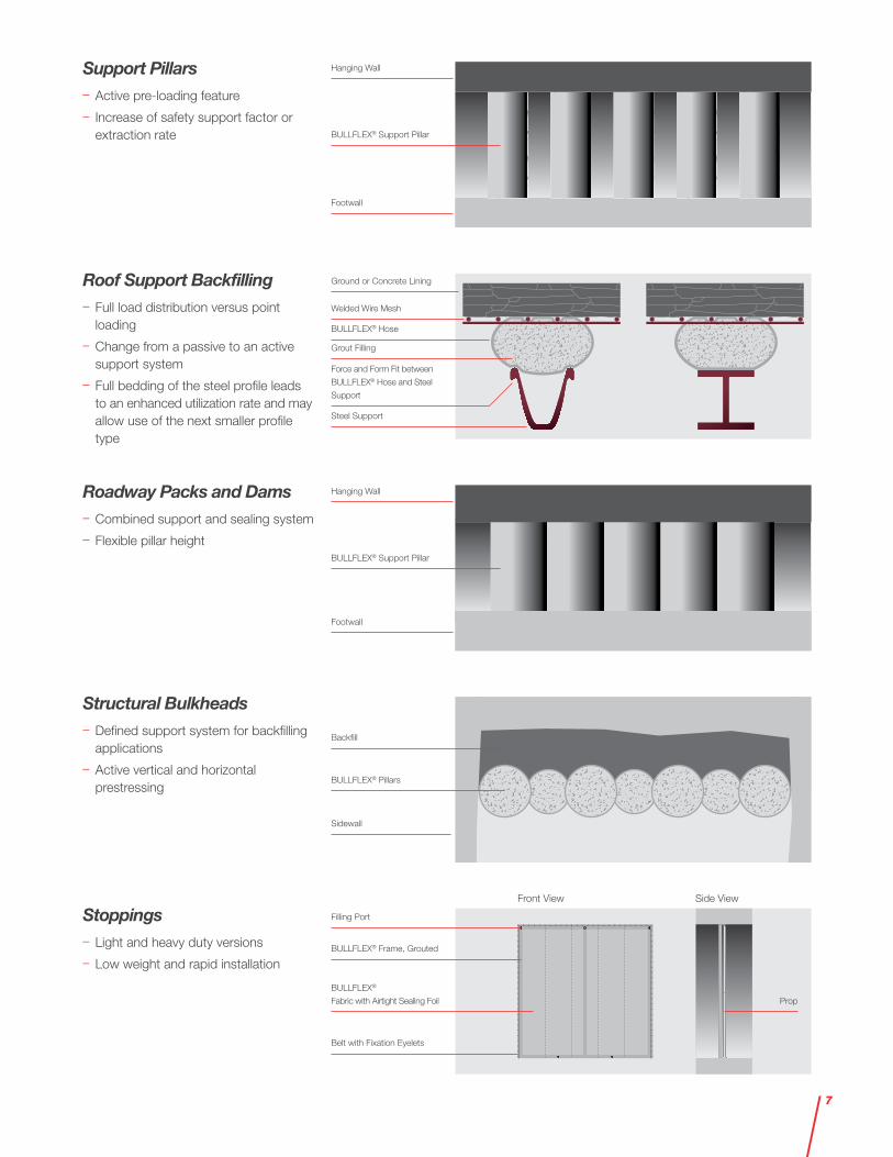
Ground or Concrete Lining
Hanging Wall
Hanging Wall
Footwall
Footwall
BULLFLEX® Pillars
Backfill
Sidewall
Belt with Fixation Eyelets
BULLFLEX® Frame, Grouted
BULLFLEX®
Fabric with Airtight Sealing Foil
Front View Side View
Prop
Filling Port
BULLFLEX® Hose
Grout Filling
Steel Support
BULLFLEX® Support Pillar
BULLFLEX® Support Pillar
Welded Wire Mesh
Force and Form Fit between
BULLFLEX® Hose and Steel
Support
Support Pillars – Active pre-loading feature
– Increase of safety support factor or extraction rate
Roof Support Backfilling – Full load distribution versus point loading
– Change from a passive to an active support system
– Full bedding of the steel profile leads to an enhanced utilization rate and may allow use of the next smaller profile type
Structural Bulkheads – Defined support system for backfilling applications
– Active vertical and horizontal prestressing
Stoppings – Light and heavy duty versions
– Low weight and rapid installation
Roadway Packs and Dams – Combined support and sealing system
– Flexible pillar height
7

100
100
Ø 32 Ø 50
Ø 40 Ø 63
Ø 136 Ø 176
100
Ø 50
Ø 63
Ø 176
System Components
Filling Port DN 32 DN 50
Ø [mm] 28 45
Thread ["] 1 ¼ 2
– BULLFLEX® filling ports - Pre-manufactured with integrated upper closure, filling port(s), and bottom plate - With check valve, inner diameter 32 [mm] (1¼ [in]) or 50 [mm] (2 [in]) - Number of filling ports depending on the length/height of the BULLFLEX® groutable hoses
– BULLFLEX® filling nozzle
– BULLFLEX® multiple-use formworks - For installation of larger-size BULLFLEX® groutable hoses, multiple-use steel formworks are required - Stabilization and fixation during installation (inflation)
– Filling material - See table for recommended injection material
– BULLFLEX® groutable hoses - Endless round woven hoses made of polyamide 6.6 - High resistance against tearing and no longitudinal seams - Anti-static, flame resistant, and self- extinguishing
- Working pressure up to 4 [bar] (58 [psi]) - Air and water permeable
- Retention of the grout mineral content while draining due to the special filter effect of the BULLFLEX® system
- Compliance with filter self rescuer systems
- Off-size diameters and special designs are available on request - Patented product technology
Application Diameter Length / Height
[–] [mm] [in] [m] [ft]
Support pillars 280 - 960 11 - 38 1) 1.5 - 7.1 5 - 23
Roof support backfilling 230 - 400 9 - 16 Length as required
Roadway packs and dams 480 - 960 19 - 38 1) 1.5 - 7.1 5 - 23
Structural bulkheads 280 - 960 11 - 38 1) Length as required
Stoppings Flat fabric Length as required
1) Larger diameters available on request.
Welding SpotØ
Thread
Filling Nozzle DN 32 / DN 50
Filling Ports
DN 32 DN 50 DN 50 for Coarse Aggregates8

Specifications
Characteristic 1) Unit Value Remarks
Material [–] Polyamide 6.6 Nylon
Weight [g/m2] / [oz/yd2] Approx. 660 / 19.5 –
Fabric thickness [mm] / [in] Approx. 1 / 0.04 –
Minimum tensile strengthL 2)
T 3)[N] / [lbf]
12,000 / 2,69824,000 / 5,395
100 [mm] / 3.94 [in] widthAccording to ISO 10319
Corresponding maximum elongationL 2)
T 3)[%]
2020
According to ISO 10319
Elastic elongationL 2)
T 3)[%]
1515
According to ISO 10319
Minimum seam strength [kN/m] / [lbf/ft] 155 / 113 –
Airflow through fabric at pressure[mbar] ([psi])
10 (0.15)20 (0.30)30 (0.45)
[L/min] / [gal/min]6.5 / 1.713 / 3.419 / 5.0
At 100 [cm2] / 15.5 [in2]
Residual tensile strength [%] 20 - 30After 1 year and under light
exposure in Florida
1) The indicated values are laboratory values and may deviate on-site.
2) Longitudinal.
3) Transversal.
9

Cement Storage Silos with Mixing and Pumping System Ready-Mix Truck and Grout Pump
Material Logistics, Pumping, and Mixing Equipment
Two Concepts for Optimum Installation Performance
Main Factors affecting the Workabiliy of the Injection Medium – Water-cement ratio – Amount and type of aggregate and cement
– Ambient temperature – Chemical admixtures
Requirements Pumping and Mixing Equipment – Application of either a separate mixing and pumping unit, or a combined mixing/pumping device
– Pumpable with standard worm pumps for flooring or injections works with a nominal power of 7.5 to 12 [kW] and a minimum flow rate of 20 [L/min] (5 [gal/min])
– Default filling rates should be in the range of approx. 80 - 180 [L/min] (21 - 48 [gal/min])
Recommended Injection Material 1)
Characteristic Unit Value Remarks
Composition [%]25 - 50% Portland cement
75 - 50% fly ashAlternatively, stone powder or a mixture of fly ash
and sand can be used instead of fly ash 2)
Compressive strength after 1 day [N/mm²] / [psi] > 2 / > 290 EN 196 / ASTM C1019
Compressive strength after 28 days [N/mm²] / [psi] > 25 / > 3,630 EN 196 / ASTM C1019
Slump class [–] Medium-high EN 12350-5 / ASTM C143
Max. grain size [mm] / [in] 3.8 / 0.15 Default aggregate grading curve
W/C ratio [1] 0.7 - 0.9 –
Setting time [min] 30 - 120 –
1) Further references: ASTM C1107; ASTM C827; ASTM C143; EN 1045; EN 206-1.
2) Aggregates may not have constituents harmful to concrete.
Recommendations for Installation – Ensure that injection hoses are laid out without kinks, avoid contact with any sharp edges in order to prevent the fabric from being damaged
– Wherever there is a change of direction, the bending radius must be greater than six times the outside hose diameter
– Screw pumps are high-pressure pumps, therefore only steel-reinforced hoses may be used for grout transport
– Before starting the machine, ensure that easily workable grout is being used
– The intake hose must not leak anywhere (especially not at connections), and the inner side of the hoses must be sufficiently lubricated
10

Characteristics
Pillar Diameter 1)
Max. Recommended Pillar Height 2)
Active Pre-Loading 3)
Injection Material Consumption 4)
Average Inflation Time 4)
[mm] [in] [m] [ft] [kN] [kip] [m3] [ft3] [sec]
480 19 3.6 12.0 100 22 0.2 7.0 85
590 23 4.4 14.5 150 34 0.3 10.5 125
740 29 5.2 17.0 240 54 0.4 14.0 200
960 38 7.1 23.5 400 90 0.7 24.5 330
1) Other dimensions available on request.
2) At a slenderness ratio of 30, rounded.
3) Calculated at a filling pressure of 4 [bar] (58 [psi]) and for two contact areas (hanging wall and footwall), rounded.
4) Calculated for 1 [m] (3.3 [ft]) pillar height and at a flow rate of 130 [L/min] (34.5 [gal/min]), rounded.
Standard Dimensions 1)
Designation Hose Diameter Inflated Groutable Hose
[–] [mm] [in] [mm] [in]
9 - 11" 230 9 280 11
13 - 15" 320 13 380 15
16 - 19" 400 16 480 19
20 - 23" 500 20 590 23
25 - 29" 630 25 740 29
31 - 38" 800 31 960 38
1) Intermediate and larger diameters available on request.
Support Pillars
11
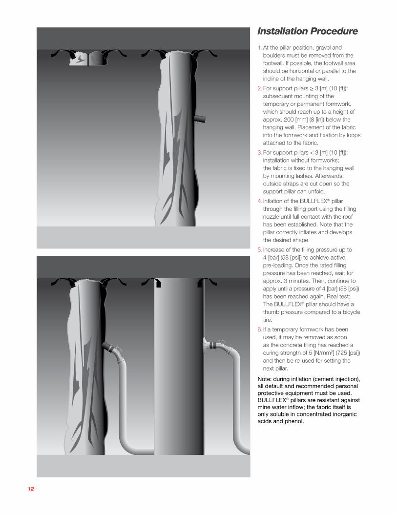
Installation Procedure
1. At the pillar position, gravel and boulders must be removed from the footwall. If possible, the footwall area should be horizontal or parallel to the incline of the hanging wall.
2. For support pillars ≥ 3 [m] (10 [ft]): subsequent mounting of the temporary or permanent formwork, which should reach up to a height of approx. 200 [mm] (8 [in]) below the hanging wall. Placement of the fabric into the formwork and fixation by loops attached to the fabric.
3. For support pillars < 3 [m] (10 [ft]): installation without formworks; the fabric is fixed to the hanging wall by mounting lashes. Afterwards, outside straps are cut open so the support pillar can unfold.
4. Inflation of the BULLFLEX® pillar through the filling port using the filling nozzle until full contact with the roof has been established. Note that the pillar correctly inflates and develops the desired shape.
5. Increase of the filling pressure up to 4 [bar] (58 [psi]) to achieve active pre-loading. Once the rated filling pressure has been reached, wait for approx. 3 minutes. Then, continue to apply until a pressure of 4 [bar] (58 [psi]) has been reached again. Real test: The BULLFLEX® pillar should have a thumb pressure compared to a bicycle tire.
6. If a temporary formwork has been used, it may be removed as soon as the concrete filling has reached a curing strength of 5 [N/mm²] (725 [psi]) and then be re-used for setting the next pillar.
Note: during inflation (cement injection), all default and recommended personal protective equipment must be used. BULLFLEX® pillars are resistant against mine water inflow; the fabric itself is only soluble in concentrated inorganic acids and phenol.
12

16 - 19" 20 - 23" 25 - 29" 31 - 38"
16 - 19" 20 - 23" 25 - 29" 31 - 38"
Height [m]
Load
-Bea
ring
Cap
acity
[kN
]
0
1,000
2,000
3,000
4,000
5,000
6,000
7,000
0.9 1.2 1.5 2.11.8 2.4 2.7 3.0 3.4 3.7
Height [ft]
Load
-Bea
ring
Cap
acity
[kip
]
0
250
500
750
1,000
1,250
1,500
3 5 7 9 114 6 8 10 12
– Load-bearing capacity depending on pillar height, calculated
– Without consideration of active setting load
– Calculation basis for pre-dimensioning, including factors of safety
– Actual in-situ load-bearing capacity determined by static load tests, exceeding the stated values
– Examined in the course of a static load test series at the NIOSH ground control laboratories (Pittsburgh, PA, USA)
– Project-specific design proposals available on request
Load-Bearing Capacity
SI Units
Type Height [m] and Load-Bearing Capacity [kN]
[in] 0.9 1.2 1.5 1.8 2.1
16 - 19" 1,570 1,522 1,474 1,427 1,379
20 - 23" 2,412 2,353 2,295 2,236 2,178
25 - 29" 3,850 3,777 3,703 3,630 3,556
31 - 38" 6,564 6,469 6,374 6,279 6,183
Type Height [m] and Load-Bearing Capacity [kN]
[in] 2.4 2.7 3.0 3.4 3.7
16 - 19" 1,332 1,284 1,236 1,189 1,141
20 - 23" 2,119 2,061 2,002 1,943 1,885
25 - 29" 3,483 3,409 3,336 3,263 3,189
31 - 38" 6,088 5,993 5,898 5,802 5,707
US Customary Units
Type Height [ft] and Load-Bearing Capacity [kip]
[in] 3 4 5 6 7
16 - 19" 353 342 331 321 310
20 - 23" 542 529 516 503 490
25 - 29" 866 849 833 816 799
31 - 38" 1,476 1,454 1,433 1,412 1,390
Type Height [ft] and Load-Bearing Capacity [kip]
[in] 8 9 10 11 12
16 - 19" 299 289 278 267 257
20 - 23" 476 463 450 437 424
25 - 29" 783 766 750 733 717
31 - 38" 1,369 1,347 1,326 1,304 1,283
13

Roof Support Backfilling
Standard Dimensions 1)
Designation Hose Diameter Inflated Groutable Hose
[–] [mm] [in] [mm] [in]
9 - 11" 230 9 280 11
13 - 15" 320 13 380 15
16 - 19" 400 16 480 19
1) Intermediate and larger diameters available on request.
Transformation Point-Load to Full-Surface Support Action
– Conventional steel support features a point-load transfer only
– Application of BULLFLEX® roof support backfilling enables a full-surface support action
– Support beams become a fully embedded and stiff system
– Optimized support action prevents further ground loosening and progressive block failure
14
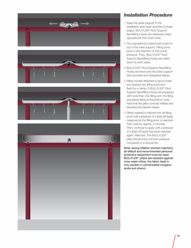
Installation Procedure
1. Keep the steel support in the installation area clean and free of sharp edges. BULLFLEX® Roof Support Backfilling Hoses are delivered coiled oppositional from both ends.
2. The oppositional coiled hose is laid on top of the steel support. Filling ports point in the direction of the tunnel entrance. Then, BULLFLEX® Roof Support Backfilling Hoses are rolled down to both sides.
3. BULLFLEX® Roof Support Backfilling Hoses are fixed onto the steel support with provided and integrated lashes.
4. Filling nozzles attached to grout hoses are inserted into filling ports and fixed by a clamp. If BULLFLEX® Roof Support Backfilling Hoses are equipped with more than one filling port, the filling procedure starts at the bottom ones. Note that the pillar correctly inflates and develops the desired shape.
5. Filling material is injected into all filling ports until a pressure of 4 [bar] (58 [psi]), measured at the filling point, is reached. Then wait for approx. 3 minutes. Then, continue to apply until a pressure of 4 [bar] (58 [psi]) has been reached again. Real test: The BULLFLEX® pillar should have a thumb pressure compared to a bicycle tire.
Note: during inflation (cement injection), all default and recommended personal protective equipment must be used. BULLFLEX® pillars are resistant against mine water inflow; the fabric itself is only soluble in concentrated inorganic acids and phenol.
15
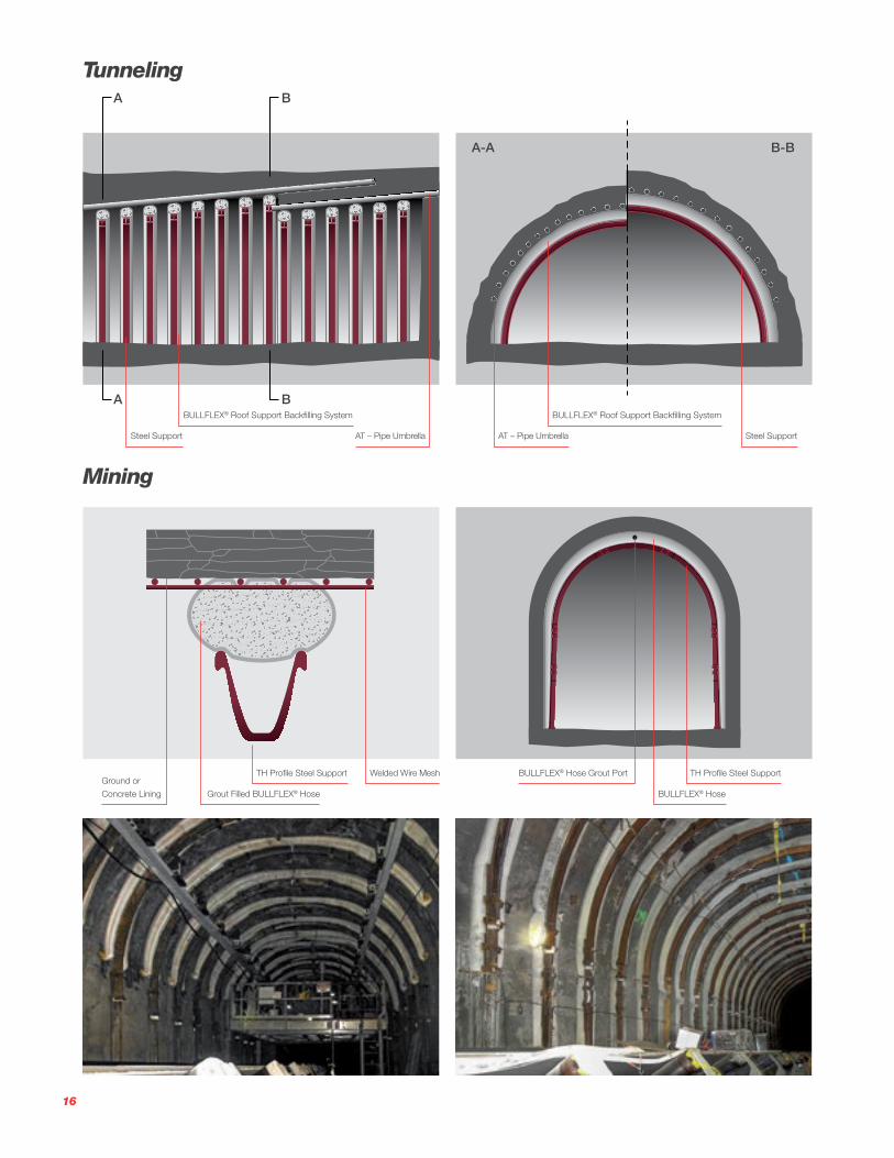
Mining
TunnelingA
A-A B-B
A
B
B
Steel Support
TH Profile Steel SupportGround or
Concrete Lining
TH Profile Steel Support Welded Wire Mesh
BULLFLEX® HoseGrout Filled BULLFLEX® Hose
BULLFLEX® Hose Grout Port
Steel SupportAT – Pipe Umbrella
BULLFLEX® Roof Support Backfilling System BULLFLEX® Roof Support Backfilling System
AT – Pipe Umbrella
16
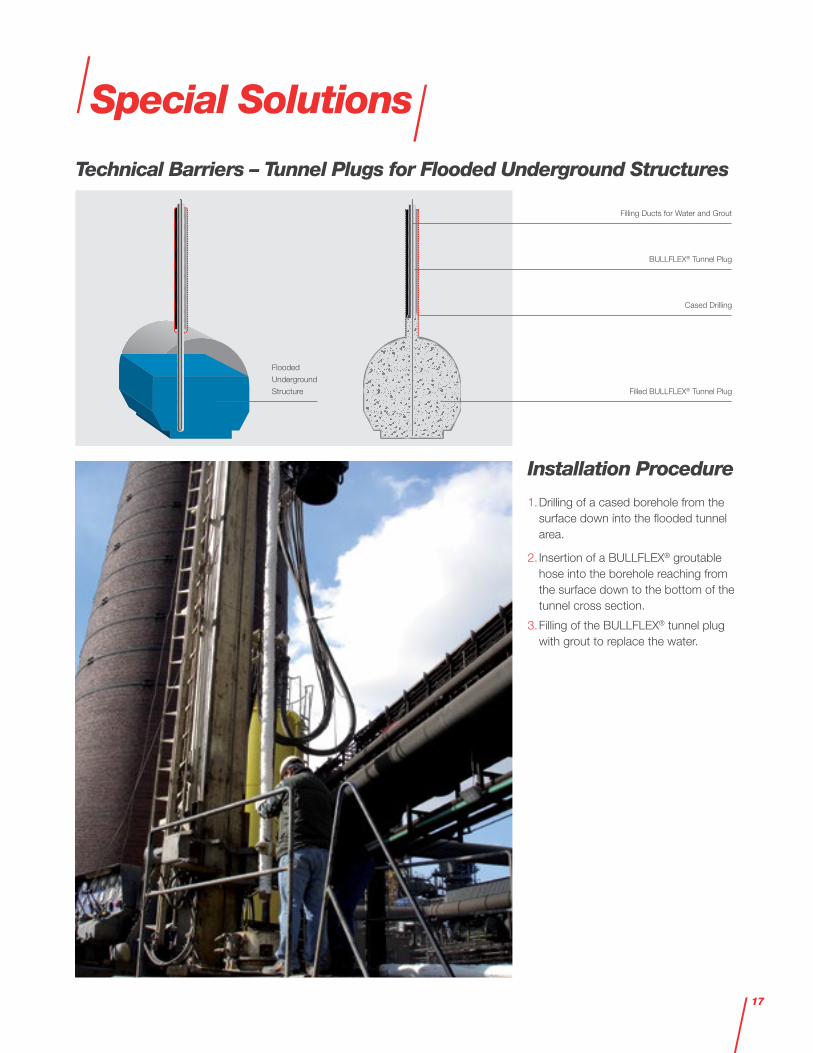
Special Solutions
Installation Procedure
1. Drilling of a cased borehole from the surface down into the flooded tunnel area.
2. Insertion of a BULLFLEX® groutable hose into the borehole reaching from the surface down to the bottom of the tunnel cross section.
3. Filling of the BULLFLEX® tunnel plug with grout to replace the water.
Technical Barriers – Tunnel Plugs for Flooded Underground Structures
Filling Ducts for Water and Grout
BULLFLEX® Tunnel Plug
Cased Drilling
Filled BULLFLEX® Tunnel Plug
Flooded
Underground
Structure
17

Mine Rehabilitation – Safekeeping Measures
Artificial Pillars
18
– Van Zanten, R. V.: Geotextiles and Geomembranes in Civil Engineering. A.A. Balkema. Rotterdam/Boston, 1986. ISBN 90 6191 6240. Page 156 ff.
– Safe application of mine roadway support systems. Rock Mechanics Technology Ltd, 2004. ISBN 0 7176 2847 7
– Breinig, F., Opolony, K.: Geplante Doppelnutzung einer Rechteckankerstrecke in 1200 m Teufe im Flöz D2/C. Martens, P.N. (ed): Aachen International Mining Symposia 2004. Glückauf, Essen, 2004. Page 159 ff.
– Declaration of conformity and material data sheets
– German approval for Underground application (No. 18.43.21-61-40)
– British COAL acceptance scheme (No. NMM 5318) for the use of the material (fabric) as Underground support element
– Nitschke, A.G. et al.: Innovative Rehabilitation of Existing Tunnels Under Minimum Impact on Operation. 2015 SME Annual Meeting, Preprint 15-131, February 2015
Further References
Bracing Cushions Levelling Caissons
19

1006
5-1/
05.2
1-w
eb H
e
DSI Underground Austria GmbH Alfred-Wagner-Strasse 1 4061 Pasching/Linz Austria
Phone +43 7229 610490 E-mail [email protected]
www.dsiunderground.at
US-B 7,080,697, AT-E 0 332 436, 502 07 438.8-08, ES 2262838 T5, EP-B 1 381 756, EP-B 1 381 756, TR 2006 03585 T4, AT-B 504 022, DE-C 101 05 827, DE 101 19569, HK 1066581, AT-B 501 875, AT-E 0 372 442, 50 2004 004 906.0-08, EP-B 1 682 745, AT-E 0 202 045, 598 00 872.1, AT-E 0 514 836, EP-B 0 1 888 878, AT-E 0 549 545, EP-B 1 886 056, 50 2006 004 522.2-08, EP-B 1 886 056, AT-E 715 471, DE 50 2006 014 239.2, EP-B 1 915 505, AT-B 508 617, AT-U 12 096, DE 10 2009 038 813, DE 10 2007 012 220, DE 10 2007 029548, AT-U12444, AT-B 512 243, AT-E 614 034, EP-B 2 473 296, AT-U 13 162, AT-U 13 292, AT-E 705 881, EP-B 2 556 205, AT-U 13 738, AT-U 14 223, 14 450 008.9, AT-E 832 944, 50 2013 004 779.2, EP-B 2 836 680, AT-U 14 877, AT-U 15014, AT-U 15 453, AT-U 15 452, AT-E 926 230, 50 2014 005 373.6, EP-B 3 027 920
“ALWAG” (AM 952/79, AM 3571/2008), “AT” (AM 6138/2003), “AT-SYSTEM” (AM 6139/2003), “LSC” (AM 4326/2008), “OMEGA-BOLT®” (3258282), “POWER SET” (AM 6163/2002), “ALWAGRIP” (AM 4327/2008), and “TUBESPILE” (AM 4328/2008) are registered trademarks of DSI Underground“BULLFLEX®” is a trademark of BuM Beton- und Monierbau GmbH.
Please note: This brochure serves basic informationpurposes only. Technical data and informationprovided herein shall be considerednon-binding and may be subject to changewithout notice. We do not assume any liabilityfor losses or damages attributed to the useof this technical data and any improperuse of our products. Should you requirefurther information on particular products,please do not hesitate to contact us.