building services project 2 proposal report
TRANSCRIPT
0
PROJECT 2
BUILDING SERVICES
FOR OLD FOLKS HOME
BUILDING SERVICES
(BLD 60903)
Prepared By : Aida Junita 0317766
Ong Jia Hui 0317752
Ong Min Junn 0317767
Tan Wen Hao 0319923
Tang Pei Kei 0318545
Wong Zhen Fai 0317890
Tutor : Dr. Sivaraman Kuppusamy
1
Index
1.0 Introduction 2
2.0 Passive Fire Protection System 3
2.1 Literature Reviews 3
2.2 Introduction to passive fire protection system 5
2.3 Components of passive fire protection system 6
2.4 Overall passive fire protection system diagram on plan 27
3.0 Active Fire Protection System 29
3.1 Literature Reviews 29
3.2 Introduction to Active Fire Protection System 31
3.3 Components of Active Fire Protection System 32
3.4 Appendix 52
4.0 Passive Ventilation System 53
4.1 Literature Reviews 53
4.2 Introduction for Passive Ventilation within the Centre 55
4.3 Openings for Ventilation within Spaces 55
5.0 Mechanical Ventilation System 63
5.1 Literature Reviews 63
5.2 Operation System of Mechanical Ventilation 65
5.3 Appendix 74
6.0 Air Conditioning System 75
6.1 Literature Review 75
6.2 Introduction on Packaged Unit System 76
6.3 Integration of Packaged Unit System to Site 76
6.4 Product Specifications 82
6.5 Appendix 83
7.0 Mechanical Transport System 84
7.1 Literature Review 84
7.2 Findings & Analysis of Elevators 86
7.3 Proposal of Systems 96
8.0 Appendix 100
9.0 References 112
2
1.0 Introduction
COMMUNITY LIBRARY
Decades ago, Taman Kanagapuram was a lively neighborhood with residents that would walk
their dogs and visit each other regularly. However, with the rise of commercial developments
and crime rate, the residents have grown wary of the surroundings and youths, thus, staying
indoors, creating a desert for the soul. The community library serves to allow the elderlies
who are mostly educated to engage in human library and mentorship programs with the
uneducated and illiterate youth which would improve community integration.
As to cater for the elderly community, the community library’s services has to be elderly-
friendly to ensure minimal accidents while ensuring a comfortable space for each individual.
In case of emergency, the services are to ensure a proper system to tackle the problem and to
minimise any injury or casualty.
3
2.0 Fire Protection System (Passive)
2.1 Literature Review
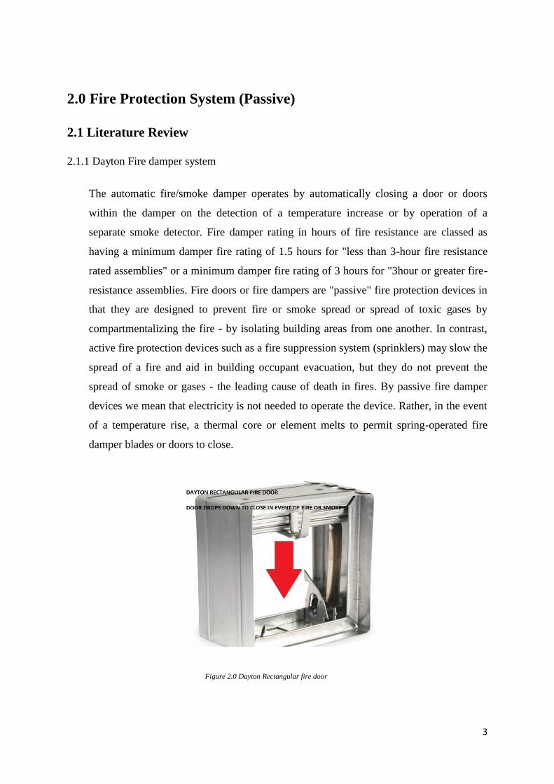
2.1.1 Dayton Fire damper system
The automatic fire/smoke damper operates by automatically closing a door or doors
within the damper on the detection of a temperature increase or by operation of a
separate smoke detector. Fire damper rating in hours of fire resistance are classed as
having a minimum damper fire rating of 1.5 hours for "less than 3-hour fire resistance
rated assemblies" or a minimum damper fire rating of 3 hours for "3hour or greater fire-
resistance assemblies. Fire doors or fire dampers are "passive" fire protection devices in
that they are designed to prevent fire or smoke spread or spread of toxic gases by
compartmentalizing the fire - by isolating building areas from one another. In contrast,
active fire protection devices such as a fire suppression system (sprinklers) may slow the
spread of a fire and aid in building occupant evacuation, but they do not prevent the
spread of smoke or gases - the leading cause of death in fires. By passive fire damper
devices we mean that electricity is not needed to operate the device. Rather, in the event
of a temperature rise, a thermal core or element melts to permit spring-operated fire
damper blades or doors to close.
Figure 2.0 Dayton Rectangular fire door
4
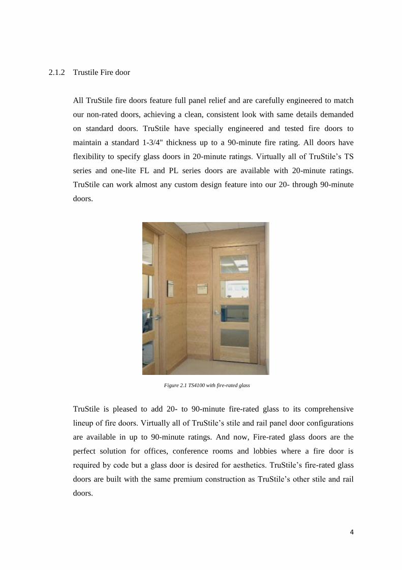
2.1.2 Trustile Fire door
All TruStile fire doors feature full panel relief and are carefully engineered to match
our non-rated doors, achieving a clean, consistent look with same details demanded
on standard doors. TruStile have specially engineered and tested fire doors to
maintain a standard 1-3/4" thickness up to a 90-minute fire rating. All doors have
flexibility to specify glass doors in 20-minute ratings. Virtually all of TruStile’s TS
series and one-lite FL and PL series doors are available with 20-minute ratings.
TruStile can work almost any custom design feature into our 20- through 90-minute
doors.
TruStile is pleased to add 20- to 90-minute fire-rated glass to its comprehensive
lineup of fire doors. Virtually all of TruStile’s stile and rail panel door configurations
are available in up to 90-minute ratings. And now, Fire-rated glass doors are the
perfect solution for offices, conference rooms and lobbies where a fire door is
required by code but a glass door is desired for aesthetics. TruStile’s fire-rated glass
doors are built with the same premium construction as TruStile’s other stile and rail
doors.
Figure 2.1 TS4100 with fire-rated glass
5
2.2 Introduction to passive fire protection system
As its name suggests, passive fire protection (PFP) is a form of fire safety provision that
remains dormant, or inert, during normal conditions but becomes active in a fire
situation. It is an integral component of structural fire protection in a building, which is
designed to contain fires or slow their spread. The purpose of PFP is to contain the
spread of fire for sufficient time to permit:
i) the safe evacuation of all occupants of the premises and
ii) the arrival of the fire brigade.
The person responsible for fire safety also has a duty of care towards any members of
the emergency services, e.g. fire fighters, who may have to enter the premises during
the course of a fire; in slowing the spread of flames, smoke and hot gases, PFP also
serves to ensure the building remains as safe as possible for entry in this situation. PFP
provision is required in all buildings, whether domestic or non-domestic, with the
purpose of containing / compartmentalising / retarding the spread of fire.
6
2.3 Components of passive fire protection system
2.3.2 Fire stopping system
2.3.1.1 Fire protection on A/C system
i. Introduction & Function
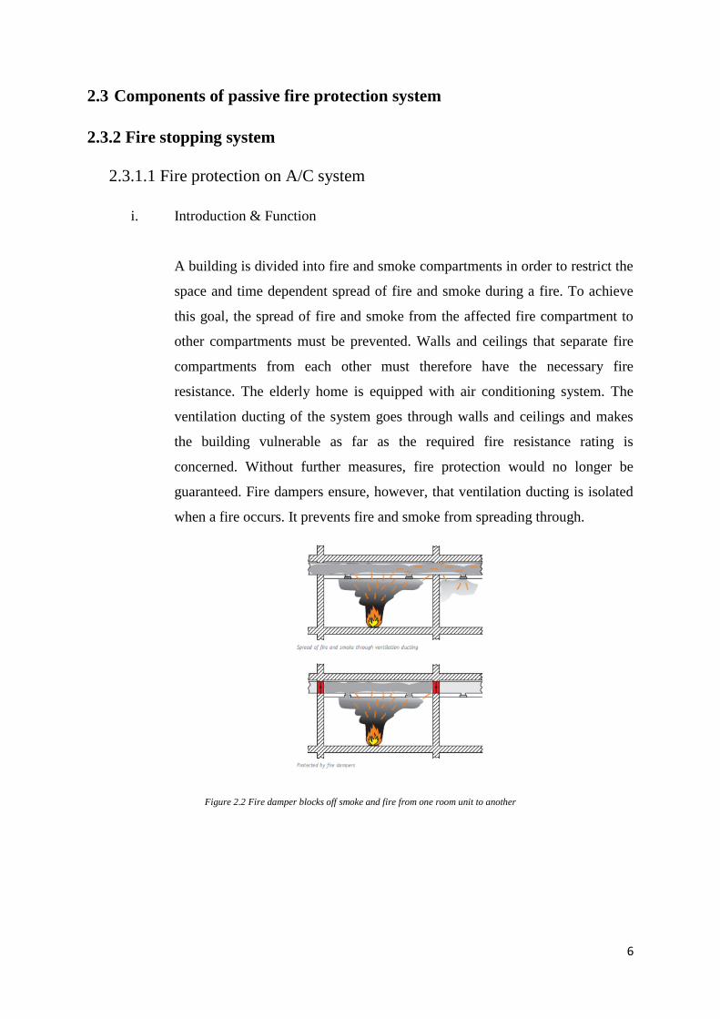
A building is divided into fire and smoke compartments in order to restrict the
space and time dependent spread of fire and smoke during a fire. To achieve
this goal, the spread of fire and smoke from the affected fire compartment to
other compartments must be prevented. Walls and ceilings that separate fire
compartments from each other must therefore have the necessary fire
resistance. The elderly home is equipped with air conditioning system. The
ventilation ducting of the system goes through walls and ceilings and makes
the building vulnerable as far as the required fire resistance rating is
concerned. Without further measures, fire protection would no longer be
guaranteed. Fire dampers ensure, however, that ventilation ducting is isolated
when a fire occurs. It prevents fire and smoke from spreading through.
Figure 2.2 Fire damper blocks off smoke and fire from one room unit to another
7
ii. Components of system
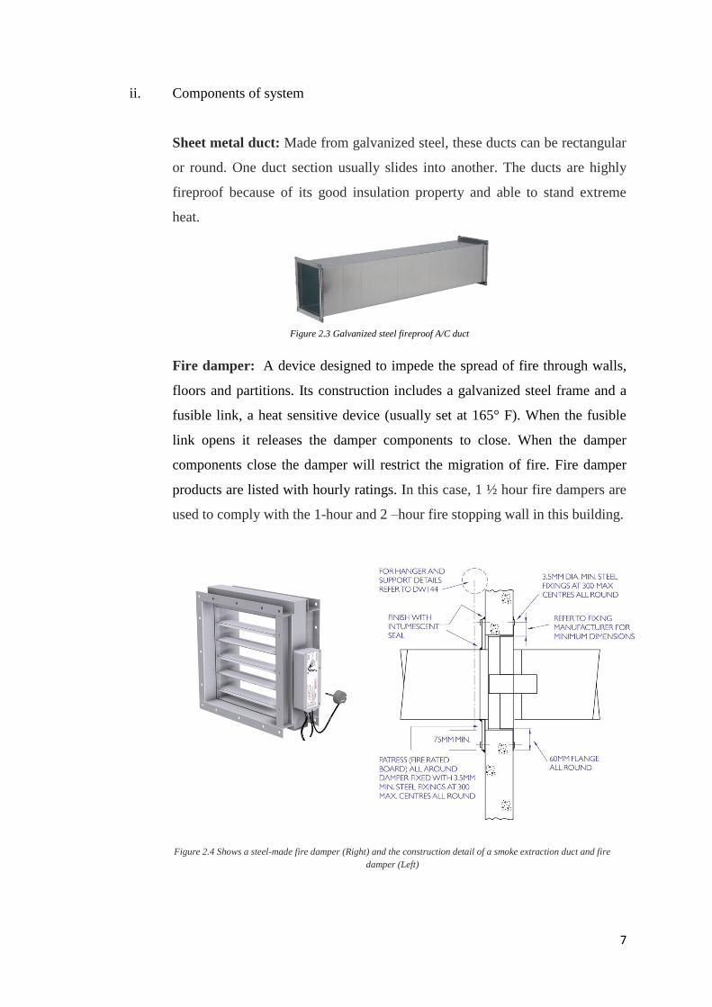
Sheet metal duct: Made from galvanized steel, these ducts can be rectangular
or round. One duct section usually slides into another. The ducts are highly
fireproof because of its good insulation property and able to stand extreme
heat.
Fire damper: A device designed to impede the spread of fire through walls,
floors and partitions. Its construction includes a galvanized steel frame and a
fusible link, a heat sensitive device (usually set at 165° F). When the fusible
link opens it releases the damper components to close. When the damper
components close the damper will restrict the migration of fire. Fire damper
products are listed with hourly ratings. In this case, 1 ½ hour fire dampers are
used to comply with the 1-hour and 2 –hour fire stopping wall in this building.
Figure 2.3 Galvanized steel fireproof A/C duct
Figure 2.4 Shows a steel-made fire damper (Right) and the construction detail of a smoke extraction duct and fire
damper (Left)
8
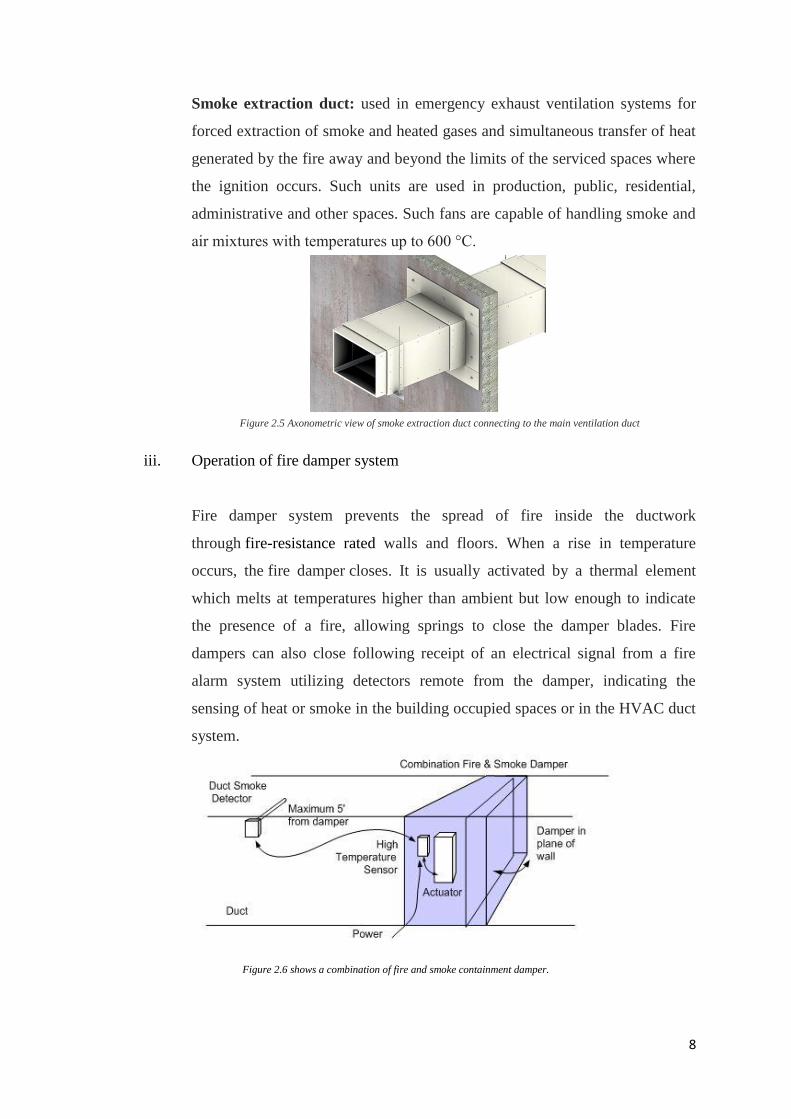
Smoke extraction duct: used in emergency exhaust ventilation systems for
forced extraction of smoke and heated gases and simultaneous transfer of heat
generated by the fire away and beyond the limits of the serviced spaces where
the ignition occurs. Such units are used in production, public, residential,
administrative and other spaces. Such fans are capable of handling smoke and
air mixtures with temperatures up to 600 °С.
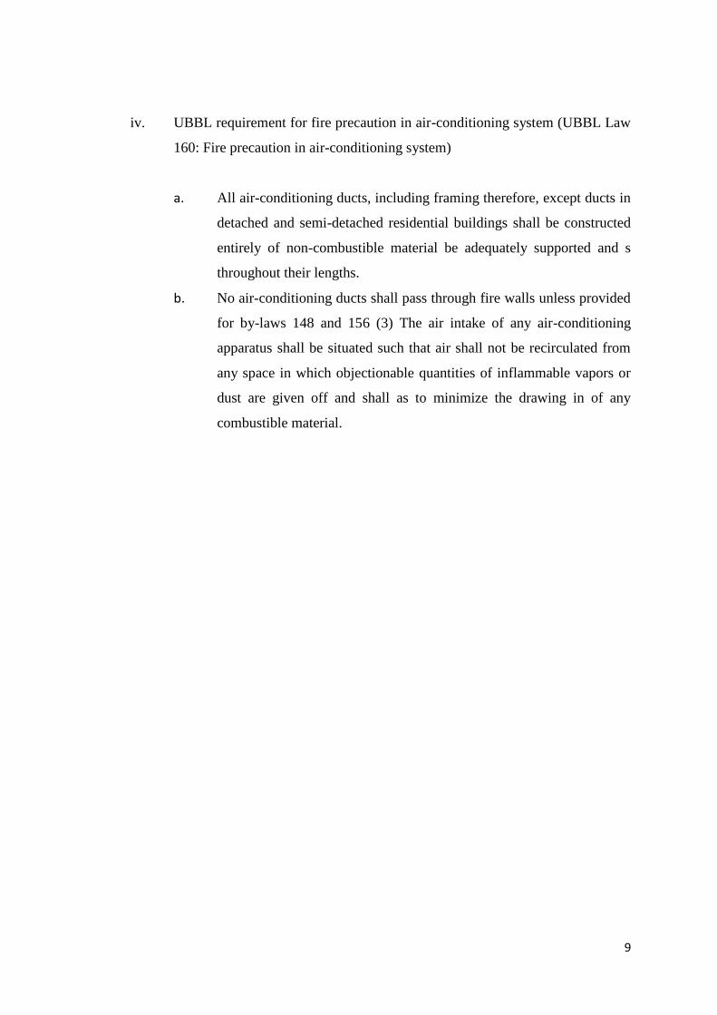
iii. Operation of fire damper system
Fire damper system prevents the spread of fire inside the ductwork
through fire-resistance rated walls and floors. When a rise in temperature
occurs, the fire damper closes. It is usually activated by a thermal element
which melts at temperatures higher than ambient but low enough to indicate
the presence of a fire, allowing springs to close the damper blades. Fire
dampers can also close following receipt of an electrical signal from a fire
alarm system utilizing detectors remote from the damper, indicating the
sensing of heat or smoke in the building occupied spaces or in the HVAC duct
system.
Figure 2.6 shows a combination of fire and smoke containment damper.
Figure 2.5 Axonometric view of smoke extraction duct connecting to the main ventilation duct
9
iv. UBBL requirement for fire precaution in air-conditioning system (UBBL Law
160: Fire precaution in air-conditioning system)
a. All air-conditioning ducts, including framing therefore, except ducts in
detached and semi-detached residential buildings shall be constructed
entirely of non-combustible material be adequately supported and s
throughout their lengths.
b. No air-conditioning ducts shall pass through fire walls unless provided
for by-laws 148 and 156 (3) The air intake of any air-conditioning
apparatus shall be situated such that air shall not be recirculated from
any space in which objectionable quantities of inflammable vapors or
dust are given off and shall as to minimize the drawing in of any
combustible material.

10
2.3.1.2 Fire-stopping wall
i. Introduction & Function
A firestop is a fire protection system made of various components used to
seal openings and joints in fire-resistance rated wall or floor assemblies.
Firestops are designed to restore the fire-resistance of wall or floor assemblies,
impeding the spread of fire by filling the openings with fire-resistant materials.
Unprotected openings in fire separations cancel out the fire-resistance ratings
of the fire separations, allowing the spread of fire, usually past the limits of
the fire safety plan of a building.
Figure 2.7 section of fire-stopping wall to floor slab
11
ii. Components of fire-stopping wall
The tree elements of fire-stopping wall are the fire-rated walls, partitions,
floors or ceilings being penetrated; the cables, cable trays or conduits that
make up the object creating the penetration; and the materials and methods
used to seal the penetrations to prevent the spread of fire and smoke.
In addition to these elements, an installation designer or contractor making
an installation must consider whether or not the penetrations will remain
permanent; the penetrations may change during the renovations of new
tenants' accommodations, which may require new electrical-system
installations.
Permanent penetrations include those made for building power, while
telephone and data-cable penetrations may be changed or reused by a
contractor during the building's history.
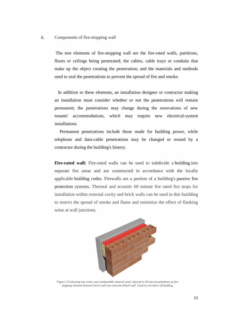
Fire-rated wall: Fire-rated walls can be used to subdivide a building into
separate fire areas and are constructed in accordance with the locally
applicable building codes. Firewalls are a portion of a building's passive fire
protection systems. Thermal and acoustic 60 minute fire rated fire stops for
installation within external cavity and brick walls can be used in this buiilding
to restrict the spread of smoke and flame and minimize the effect of flanking
noise at wall junctions.
Figure 2.8 showing low resin, non-combustible mineral wool, sleeved in 50 micron polythene as fire
stopping element between brick wall can concrete-block wall. Used in corridors of building.
12
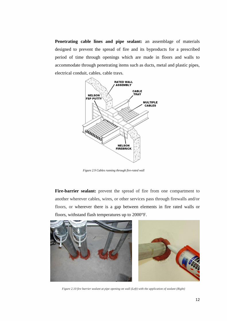
Penetrating cable lines and pipe sealant: an assemblage of materials
designed to prevent the spread of fire and its byproducts for a prescribed
period of time through openings which are made in floors and walls to
accommodate through penetrating items such as ducts, metal and plastic pipes,
electrical conduit, cables, cable trays.
Fire-barrier sealant: prevent the spread of fire from one compartment to
another wherever cables, wires, or other services pass through firewalls and/or
floors, or wherever there is a gap between elements in fire rated walls or
floors, withstand flash temperatures up to 2000°F.
Figure 2.10 fire barrier sealant at pipe opening on wall (Left) with the application of sealant (Right)
Figure 2.9 Cables running through fire-rated wall
13
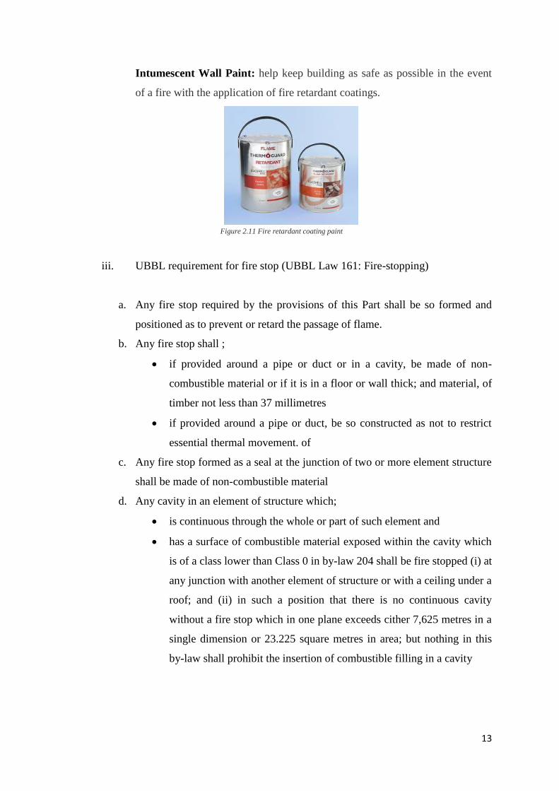
Intumescent Wall Paint: help keep building as safe as possible in the event
of a fire with the application of fire retardant coatings.
iii. UBBL requirement for fire stop (UBBL Law 161: Fire-stopping)
a. Any fire stop required by the provisions of this Part shall be so formed and
positioned as to prevent or retard the passage of flame.
b. Any fire stop shall ;
if provided around a pipe or duct or in a cavity, be made of non-
combustible material or if it is in a floor or wall thick; and material, of
timber not less than 37 millimetres
if provided around a pipe or duct, be so constructed as not to restrict
essential thermal movement. of
c. Any fire stop formed as a seal at the junction of two or more element structure
shall be made of non-combustible material
d. Any cavity in an element of structure which;
is continuous through the whole or part of such element and
has a surface of combustible material exposed within the cavity which
is of a class lower than Class 0 in by-law 204 shall be fire stopped (i) at
any junction with another element of structure or with a ceiling under a
roof; and (ii) in such a position that there is no continuous cavity
without a fire stop which in one plane exceeds cither 7,625 metres in a
single dimension or 23.225 square metres in area; but nothing in this
by-law shall prohibit the insertion of combustible filling in a cavity
Figure 2.11 Fire retardant coating paint
14
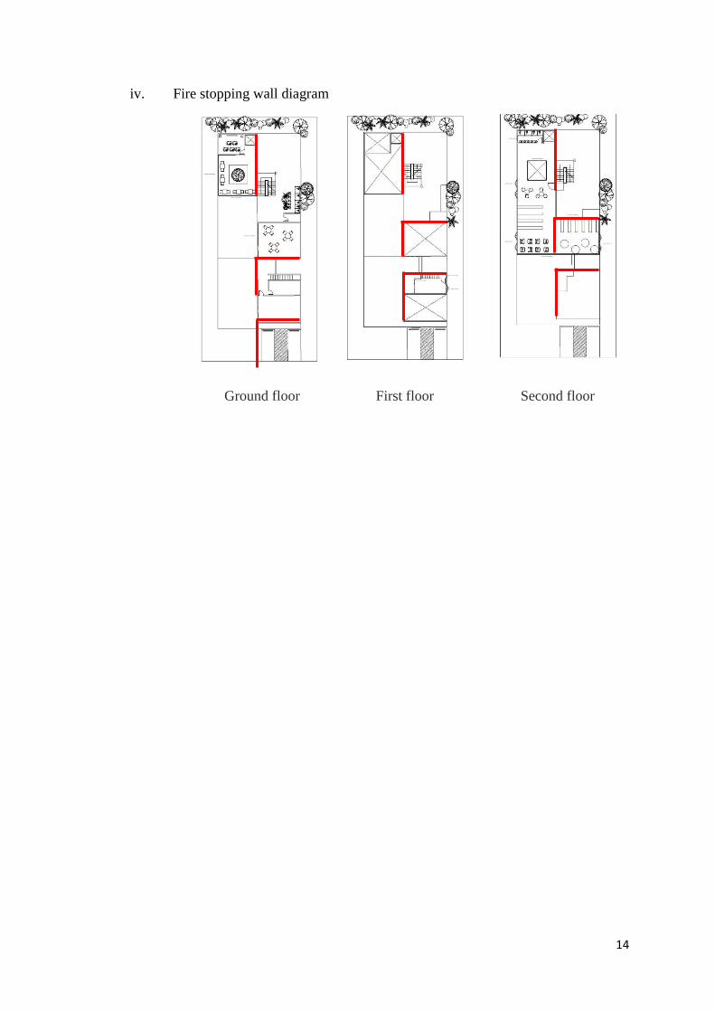
iv. Fire stopping wall diagram
Ground floor First floor Second floor
15
2.3.2 Means of Escape
2.3.2.1 Exits (half hour and one hour door)
i. Introduction & function
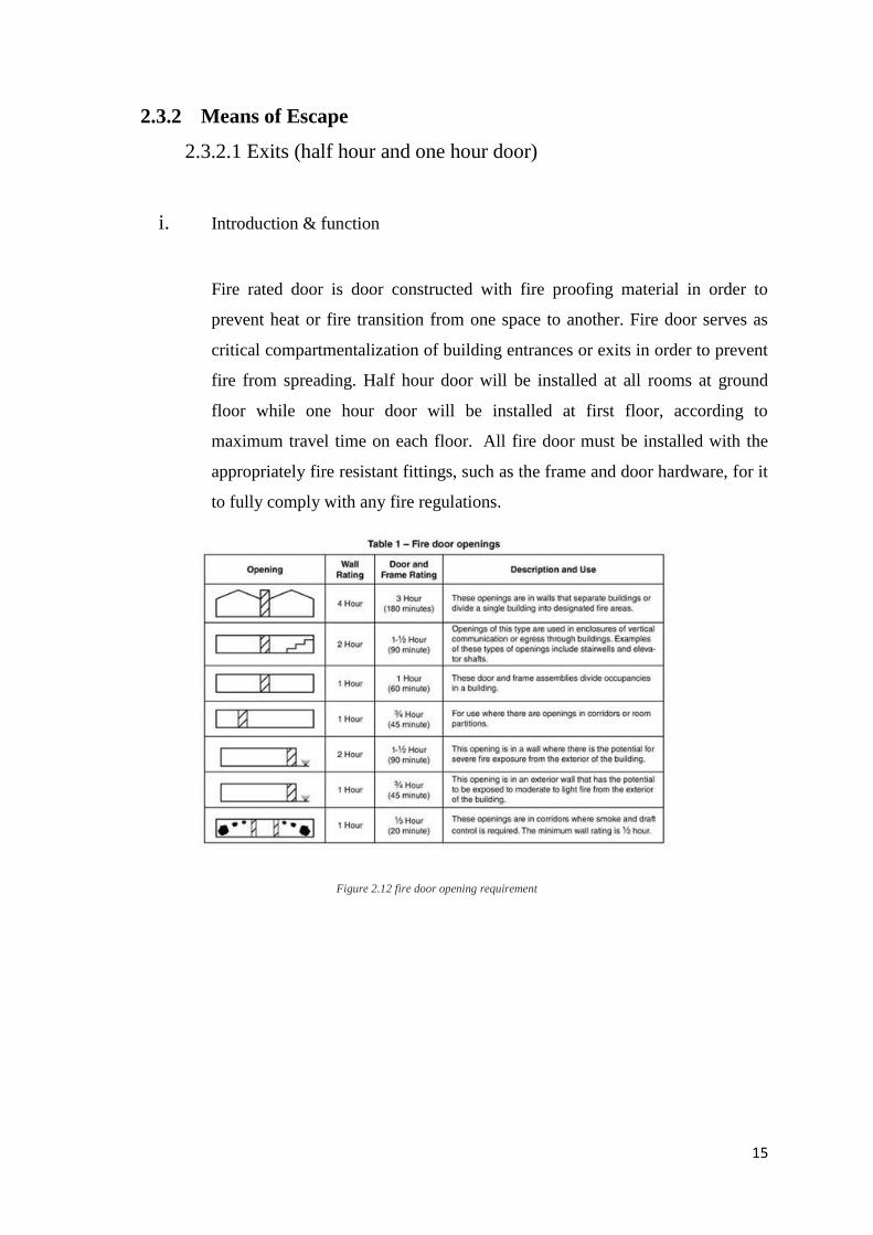
Fire rated door is door constructed with fire proofing material in order to
prevent heat or fire transition from one space to another. Fire door serves as
critical compartmentalization of building entrances or exits in order to prevent
fire from spreading. Half hour door will be installed at all rooms at ground
floor while one hour door will be installed at first floor, according to
maximum travel time on each floor. All fire door must be installed with the
appropriately fire resistant fittings, such as the frame and door hardware, for it
to fully comply with any fire regulations.
Figure 2.12 fire door opening requirement
16
ii. Components in fire-rated door
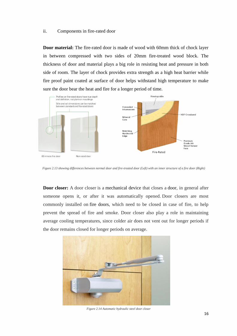
Door material: The fire-rated door is made of wood with 60mm thick of chock layer
in between compressed with two sides of 20mm fire-treated wood block. The
thickness of door and material plays a big role in resisting heat and pressure in both
side of room. The layer of chock provides extra strength as a high heat barrier while
fire proof paint coated at surface of door helps withstand high temperature to make
sure the door bear the heat and fire for a longer period of time.
Door closer: A door closer is a mechanical device that closes a door, in general after
someone opens it, or after it was automatically opened. Door closers are most
commonly installed on fire doors, which need to be closed in case of fire, to help
prevent the spread of fire and smoke. Door closer also play a role in maintaining
average cooling temperatures, since colder air does not vent out for longer periods if
the door remains closed for longer periods on average.
Figure 2.13 showing differences between normal door and fire-treated door (Left) with an inner structure of a fire door (Right)
Figure 2.14 Automatic hydraulic steel door closer
17
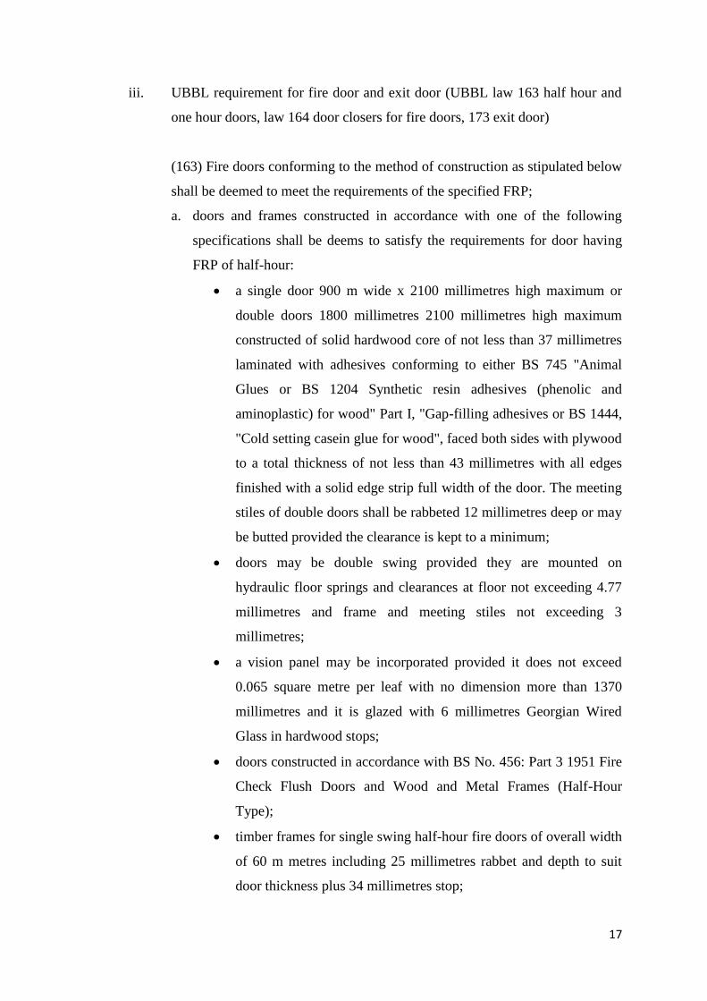
iii. UBBL requirement for fire door and exit door (UBBL law 163 half hour and
one hour doors, law 164 door closers for fire doors, 173 exit door)
(163) Fire doors conforming to the method of construction as stipulated below
shall be deemed to meet the requirements of the specified FRP;
a. doors and frames constructed in accordance with one of the following
specifications shall be deems to satisfy the requirements for door having
FRP of half-hour:
a single door 900 m wide x 2100 millimetres high maximum or
double doors 1800 millimetres 2100 millimetres high maximum
constructed of solid hardwood core of not less than 37 millimetres
laminated with adhesives conforming to either BS 745 "Animal
Glues or BS 1204 Synthetic resin adhesives (phenolic and
aminoplastic) for wood" Part I, "Gap-filling adhesives or BS 1444,
"Cold setting casein glue for wood", faced both sides with plywood
to a total thickness of not less than 43 millimetres with all edges
finished with a solid edge strip full width of the door. The meeting
stiles of double doors shall be rabbeted 12 millimetres deep or may
be butted provided the clearance is kept to a minimum;
doors may be double swing provided they are mounted on
hydraulic floor springs and clearances at floor not exceeding 4.77
millimetres and frame and meeting stiles not exceeding 3
millimetres;
a vision panel may be incorporated provided it does not exceed
0.065 square metre per leaf with no dimension more than 1370
millimetres and it is glazed with 6 millimetres Georgian Wired
Glass in hardwood stops;
doors constructed in accordance with BS No. 456: Part 3 1951 Fire
Check Flush Doors and Wood and Metal Frames (Half-Hour
Type);
timber frames for single swing half-hour fire doors of overall width
of 60 m metres including 25 millimetres rabbet and depth to suit
door thickness plus 34 millimetres stop;
18
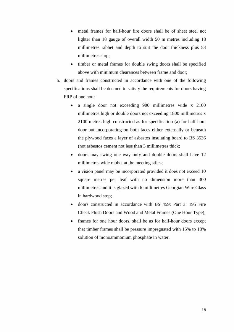
metal frames for half-hour fire doors shall be of sheet steel not
lighter than 18 gauge of overall width 50 m metres including 18
millimetres rabbet and depth to suit the door thickness plus 53
millimetres stop;
timber or metal frames for double swing doors shall be specified
above with minimum clearances between frame and door;
b. doors and frames constructed in accordance with one of the following
specifications shall be deemed to satisfy the requirements for doors having
FRP of one hour
a single door not exceeding 900 millimetres wide x 2100
millimetres high or double doors not exceeding 1800 millimetres x
2100 metres high constructed as for specification (a) for half-hour
door but incorporating on both faces either externally or beneath
the plywood faces a layer of asbestos insulating board to BS 3536
(not asbestos cement not less than 3 millimetres thick;
doors may swing one way only and double doors shall have 12
millimetres wide rabbet at the meeting stiles;
a vision panel may be incorporated provided it does not exceed 10
square metres per leaf with no dimension more than 300
millimetres and it is glazed with 6 millimetres Georgian Wire Glass
in hardwood stop;
doors constructed in accordance with BS 459: Part 3: 195 Fire
Check Flush Doors and Wood and Metal Frames (One Hour Type);
frames for one hour doors, shall be as for half-hour doors except
that timber frames shall be pressure impregnated with 15% to 18%
solution of monoammonium phosphate in water.
19
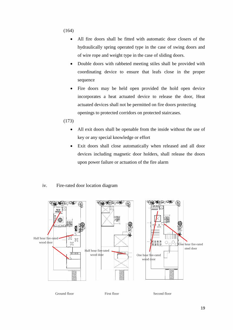
(164)
All fire doors shall be fitted with automatic door closers of the
hydraulically spring operated type in the case of swing doors and
of wire rope and weight type in the case of sliding doors.
Double doors with rabbeted meeting stiles shall be provided with
coordinating device to ensure that leafs close in the proper
sequence
Fire doors may be held open provided the hold open device
incorporates a heat actuated device to release the door, Heat
actuated devices shall not be permitted on fire doors protecting
openings to protected corridors on protected staircases.
(173)
All exit doors shall be openable from the inside without the use of
key or any special knowledge or effort
Exit doors shall close automatically when released and all door
devices including magnetic door holders, shall release the doors
upon power failure or actuation of the fire alarm
iv. Fire-rated door location diagram
Ground floor First floor Second floor
Half hour fire-rated
wood door
Half hour fire-rated
wood door One hour fire-rated
wood door
One hour fire-rated
steel door
20
2.3.2.2 Emergency exits (storey exits)
i. Introduction & function
An exit route is a continuous and unobstructed path of exit travel from any
point within a workplace to a place of safety. An exit route consists of
three parts:
Exit access – portion of an exit route that leads to an exit.
Exit – portion of an exit route that is generally separated from other
areas to provide a protected way of travel to the exit discharge.
Exit discharge – part of the exit route that leads directly outside or
to a street, walkway, refuge area, public way, or open space with
access to the outside.
ii. UBBL requirement for emergency exit (UBBL law 165 measurement of
travel distance; 166 accessibility; 167 storey exits; 169 Exit route)
(165)
The travel distance to an exit shall be measured on the floor or
other walking surface along the centre line of the natural path of
travel, starting 0.300 metre from the most remote point of
occupancy, curving around any corners or obstructions with 0.300
metre clearance therefrom and ending at the storey exit. Where
measurement includes stairs, it shall be taken in the plane of the
trend noising
In the case of open areas the distance to exits shall be measured
from the most remote point of occupancy provided that the direct
distance does not exceed two-thirds the permitted travel distance.
In the case of individual rooms which are subject to occupancy of
not more than six persons, the travel distance shall be measured
from the doors of such rooms:
21
Provided that the travel distance from any point in the room to the room
door does not exceed 15 metres.
The maximum travel distances to exists and dead end limits shall
be as specified in the Seventh Schedule of these By-laws.
(166)
Except as permitted by by-law 167 not less than two separate exits
hall provided from each storey together with such additional exits
may be necessary
The exists shall be sited and the exit access shall be so arranged
that the exits are within the limits of travel distance as specified in
the Seventh Schedule to these By-laws and are readily accessible at
all times.
(167)
Except as provided for in by-law 194 every compartment shall be
provided with at least two storey exits located as far as practical
from each other and in no case closer than 4.5 metres and in such
position that the travel distances specified in the Seventh Schedule
to these By-laws are not exceeded.
The width of storey exits shall be in accordance with the provisions
in the Seventh Schedule to these By-laws.
(169)
No exit route may reduce in width along its path of travel from the
storey exit to the final exit.
Not reduced, same throughout
22
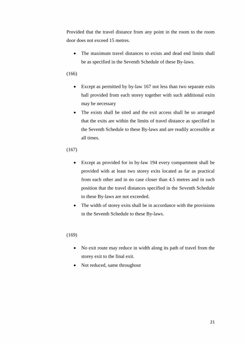
iii. Diagram of maximum travel distances - Dead-end limit (metre)
Room/ area Travel time Max. Travel Dist. Room/ area Travel time Max. Travel Dist.
Lobby 1 min 7.8M Human library 2 mins 8M
Staff office 1 min 8M M&E room 30 secs 3M
Theatre 5 mins 10M Director’s Office 4 mins 6M
Dining Lounge 2 mins 8.6M Library 6 mins 17M
Figure 14 Seventh Schedule of UBBL for maximum travel distance
Ground floor First floor Second floor
Maximum 30m of travel
distances required in an
elderly home.
Figure 2.15 Seventh Schedule of UBBL
23
2.3.2.3 Staircases
i. Introduction & function
Emergency staircases are staircases to allow the people who are found in the building from
escaping through any starting point in the building to reach the outside of the building
directly. Or to a safe place from fire, which in its turn leads to the outside of the building
where it is away from fire. These staircases must be provided in the buildings, facilities and
shops, in order to find a way out to evacuate the users and occupants of the building, and to
keep them away from the fire sector, in order to protect them and their lives from injury and
fire. The stairs are made from incombustible materials with an adequate resisting degree, and
covers the openings that overlook at the stairs with resistible doors to fire which close
automatically.
Figure 2.16 Emergency stairs (Left) with fire-stopping properties (Right)
24
ii. UBBL requirement for staircases (UBBL Law 168 Staircase)
Except as provided for in by-law 194 every upper floor shall have
means of egress via at least two separate staircase.
Staircases shall be of such width that in the event of any one
staircase not being available for escape purposes the remaining
shall accommodate the highest occupancy load of any one floor
discharging into it calculated in accordance with provisions in the
seventh schedule to these By-laws.
The required width of a staircase shall be the clear width between
walls but handrails may be permitted to encroach on this width to a
maximum of 75 millimetres.
The required width of a staircase shall be maintained throughout its
length including at landings.
Doors giving access to staircases shall be so positioned that their
swing shall at no point encroach on the required width of the
staircase or landing.
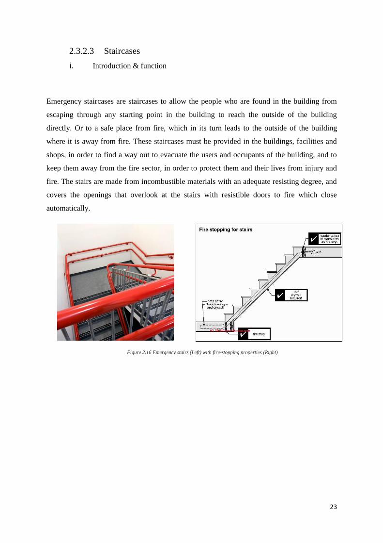
iii. Diagram of stairs location, distances and width
Ground floor First floor Second floor
Primary
emergency
stairs
Secondary
emergency
stairs
15M distances
from both stairs
Location Distances Width
25
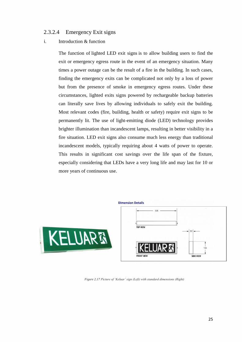
2.3.2.4 Emergency Exit signs
i. Introduction & function
The function of lighted LED exit signs is to allow building users to find the
exit or emergency egress route in the event of an emergency situation. Many
times a power outage can be the result of a fire in the building. In such cases,
finding the emergency exits can be complicated not only by a loss of power
but from the presence of smoke in emergency egress routes. Under these
circumstances, lighted exits signs powered by rechargeable backup batteries
can literally save lives by allowing individuals to safely exit the building.
Most relevant codes (fire, building, health or safety) require exit signs to be
permanently lit. The use of light-emitting diode (LED) technology provides
brighter illumination than incandescent lamps, resulting in better visibility in a
fire situation. LED exit signs also consume much less energy than traditional
incandescent models, typically requiring about 4 watts of power to operate.
This results in significant cost savings over the life span of the fixture,
especially considering that LEDs have a very long life and may last for 10 or
more years of continuous use.
he Exit Light y
Figure 2.17 Picture of ‘Keluar’ sign (Left) with standard dimensions (Right)
26
ii. UBBL requirement for emergency exit gigns (UBBL law 172)
Storey exits and access to such exits shall be marked by readily visible
signs and shall not be obscured by any decorations, furnishings or
other equipment.
A sign reading "KELUAR" with an arrow indicating the direction shall
be placed in every location where the direction of travel to reach the
nearest exit is not immediately apparent.
Every exit sign shall have the word "KELUAR" in plainly legible
letters not less than 150 millimetres high with the principal strokes of
the letters not less than 18 millimetres wide, the lettering shall be in red
against a black background.
All exit signs shall be illuminated continuously during periods of
occupancy.
Illuminated signs shall be provided with two electric lamps of not less
than fifteen watts each.
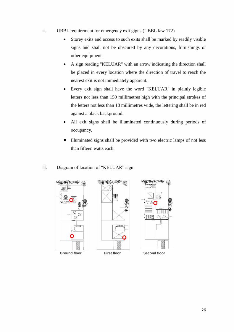
iii. Diagram of location of “KELUAR” sign
Ground floor First floor Second floor
27
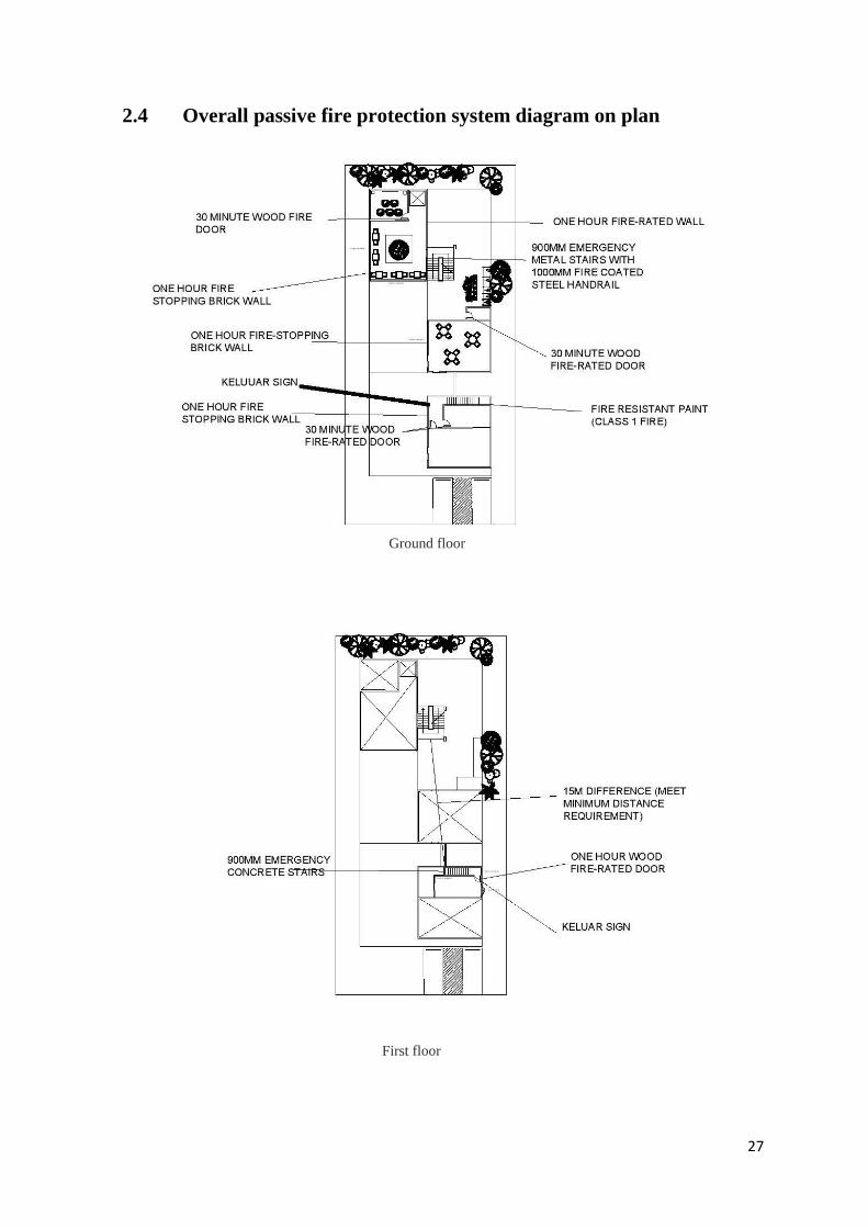
2.4 Overall passive fire protection system diagram on plan
Ground floor
First floor
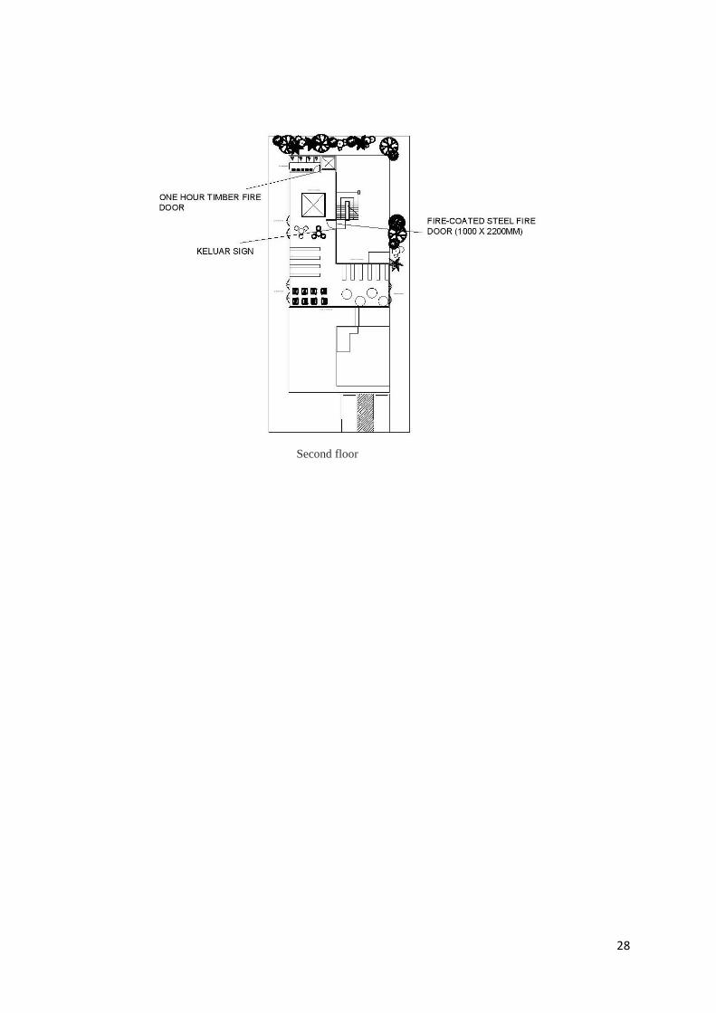
28
Second floor
29
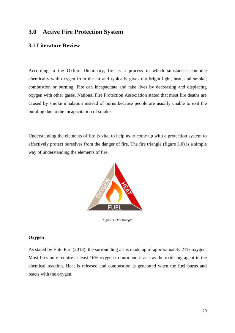
Figure 3.0 fire triangle
3.0 Active Fire Protection System
3.1 Literature Review
According to the Oxford Dictionary, fire is a process in which substances combine
chemically with oxygen from the air and typically gives out bright light, heat, and smoke;
combustion or burning. Fire can incapacitate and take lives by decreasing and displacing
oxygen with other gases. National Fire Protection Association stated that most fire deaths are
caused by smoke inhalation instead of burns because people are usually unable to exit the
building due to the incapacitation of smoke.
Understanding the elements of fire is vital to help us to come up with a protection system to
effectively protect ourselves from the danger of fire. The fire triangle (figure 3.0) is a simple
way of understanding the elements of fire.
Oxygen
As stated by Elite Fire (2013), the surrounding air is made up of approximately 21% oxygen.
Most fires only require at least 16% oxygen to burn and it acts as the oxidising agent in the
chemical reaction. Heat is released and combustion is generated when the fuel burns and
reacts with the oxygen.
30
Heat
Heat plays a critical role in the spreading of fire aside from oxygen as it warms the
surrounding area and pre-heats nearby fuel in its path. Flammable materials will combust
when heat is present as they emit flammable vapour.
Fuel
Fuel refers to any combustible materials such as oil, wood, fabric, paper, rubber, liquid and
plastic, and is needed for a fire to start. Elite Fire (2013) mentioned that the fuel for a fire is
usually characterised by its moisture content, shape, quantity and size. These factors will
determine the temperature and how easily the fuels burn.
Attempts at preventing or combatting a fire are based upon these elements and principles as
one of the three elements in the fire triangle must be removed to stop a fire. By adhering to
these fundamental principles, the pervasiveness and destruction caused by fire can be
considerably reduced.
31
3.2 Introduction to Active Fire Protection System
In relation to the danger imposed by fire, it is important to set up certain fire protection
system in a building to ensure the life safety of the occupants, which is the utmost priority in
building design. A building’s fire protection can be achieved in two forms, which are the
active and passive fire protection system.
Active Fire Protection is a group of systems that require some amount of action or motion in
order to work efficiently in the event of fire (“Active Fire Protection,” 2015). Actions may be
automatically operated, such as the sprinkler and fire alarm systems, or manually operated,
like a fire extinguisher or hose reel.
Nullifire (2014) stated that the overall aim of active systems is to extinguish the fire by:
Detecting the initial fire and evacuating the building
Alerting emergency services at an early stage of the fire
Controlling the movement of the smoke and fire
Suppressing and/or starving the fire of oxygen and fuel
Active fire protection system comes with certain benefits as they allow for more design
freedoms, encourage creativity and innovation, inclusive and sustainable architecture.
32
3.3 Components of Active Fire Protection System
3.3.1 Fire Detector and Alarm System
I. Introduction & Function
Fire alarm systems fundamentally operate upon the same basis whereby when the fire
detector detects heat or smoke (automatic operation), or when the manual pull station is
activated (manual operation), the fire alarm will then sound off to warn the occupants of the
potential of fire and to evacuate.
For a larger building, the fire alarm system composes of a central Control and Indicating
Equipment (CIE) with detectors, manual call points (MCP), interface units and sounders
connected to it (“Fire Alarm System: Introduction and Importance of Fire Alarm System”,
n.d.).
II. Components of System
A. Smoke Detector
Smoke detectors (figure 3.1) are intended to protect the property and people by
producing an alarm upon the development of fire (Baker, 2015).
Certain fire smoulders and does not produce flames, yet releases more smoke and
other poisonous gases. In this case, it is difficult to detect them using heat detectors as
they generate very minimal heat. Hence, the smoke detector is chosen for the elderly
care centre in place of a heat detector for most spaces as the old folks need time to
react, and every second is critical and matters in a genuine fire event.
33
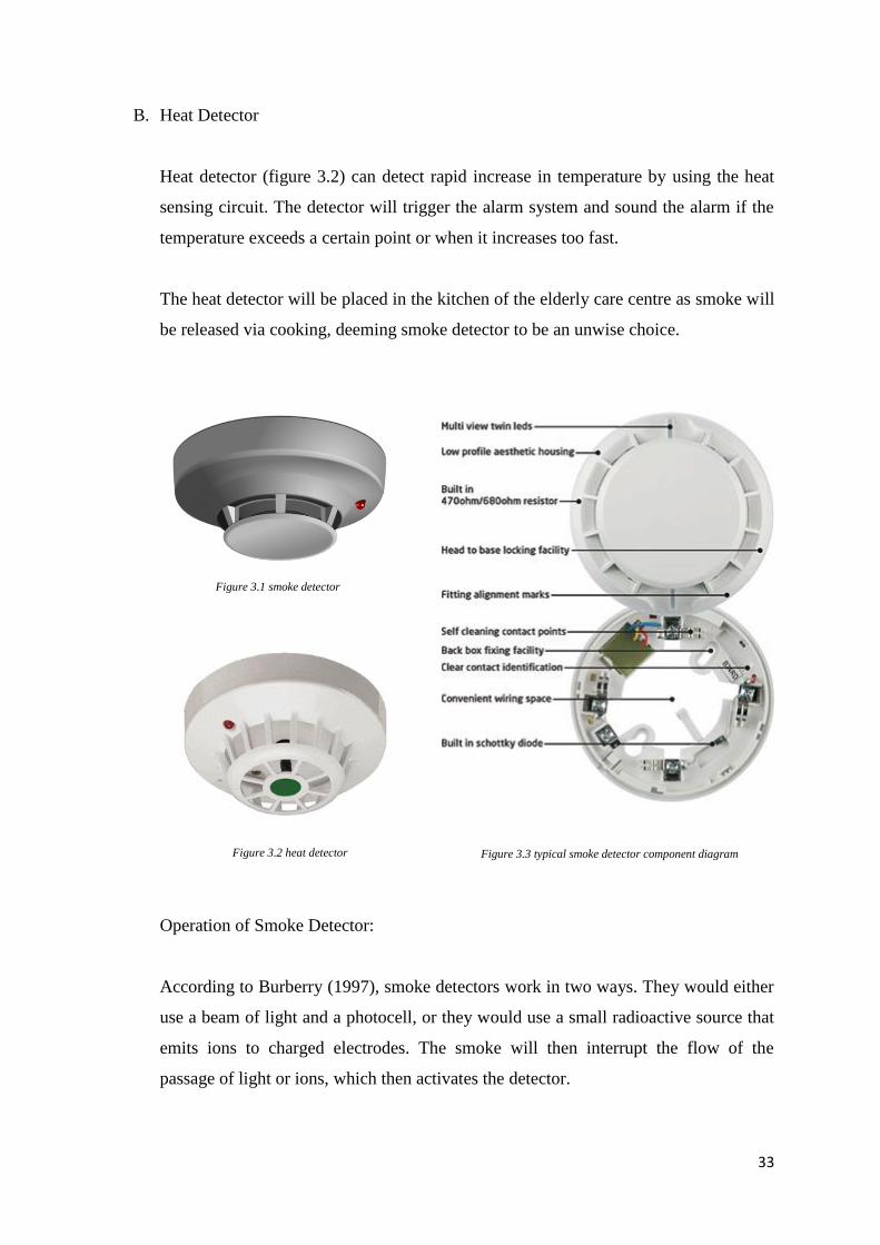
Figure 3.1 smoke detector
Figure 3.3 typical smoke detector component diagram Figure 3.2 heat detector
B. Heat Detector
Heat detector (figure 3.2) can detect rapid increase in temperature by using the heat
sensing circuit. The detector will trigger the alarm system and sound the alarm if the
temperature exceeds a certain point or when it increases too fast.
The heat detector will be placed in the kitchen of the elderly care centre as smoke will
be released via cooking, deeming smoke detector to be an unwise choice.
Operation of Smoke Detector:
According to Burberry (1997), smoke detectors work in two ways. They would either
use a beam of light and a photocell, or they would use a small radioactive source that
emits ions to charged electrodes. The smoke will then interrupt the flow of the
passage of light or ions, which then activates the detector.
34
heat detector smoke detector
max
7.5m
max 7.5m
Diagram 3.0 placement of smoke detector
Figure 3.5 maximum distance between heat detectors Figure 3.4 maximum distance between smoke detectors
UBBL requirements for smoke detector:
Law 153: Smoke detectors for lift lobbies
All lift lobbies shall be provided with smoke detectors
Law 225: Detecting and extinguishing fire
Every building shall be provided with means of detecting and extinguishing
fire and with fire alarms together with illuminated exit signs in accordance
with the requirements as specified in the Tenth Schedule to these By-laws.
max
5.3m
max 5.3m
35
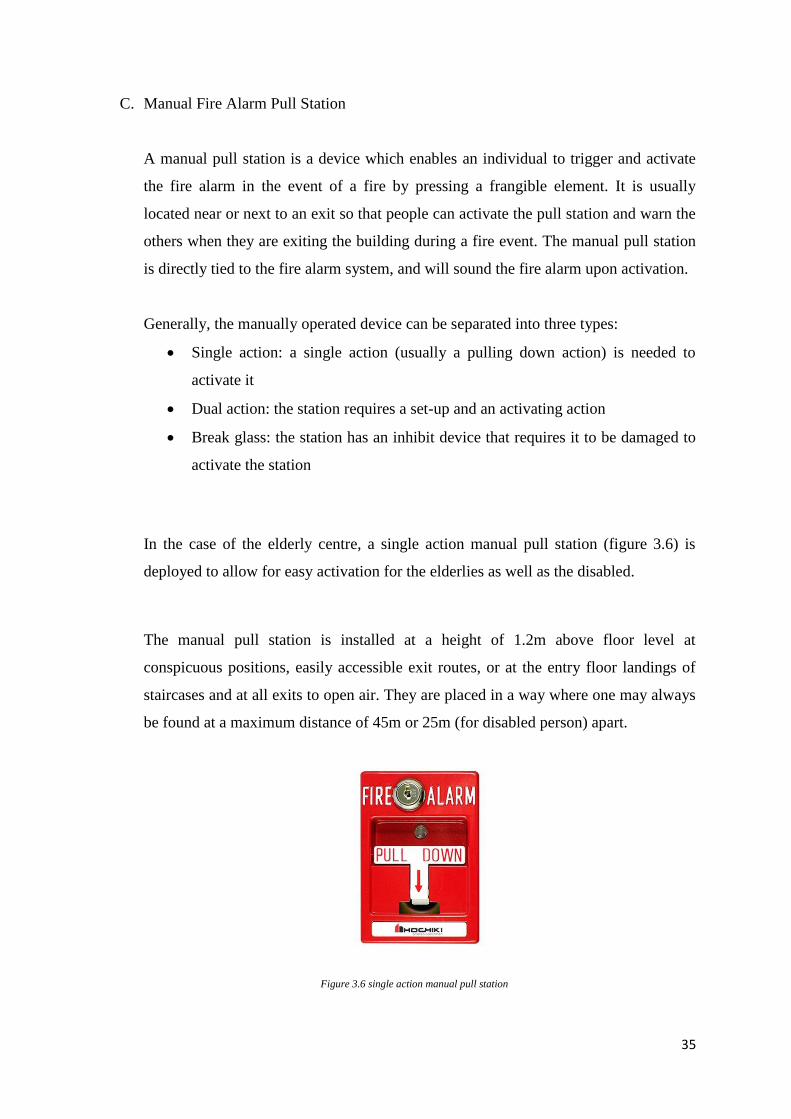
Figure 3.6 single action manual pull station
C. Manual Fire Alarm Pull Station
A manual pull station is a device which enables an individual to trigger and activate
the fire alarm in the event of a fire by pressing a frangible element. It is usually
located near or next to an exit so that people can activate the pull station and warn the
others when they are exiting the building during a fire event. The manual pull station
is directly tied to the fire alarm system, and will sound the fire alarm upon activation.
Generally, the manually operated device can be separated into three types:
Single action: a single action (usually a pulling down action) is needed to
activate it
Dual action: the station requires a set-up and an activating action
Break glass: the station has an inhibit device that requires it to be damaged to
activate the station
In the case of the elderly centre, a single action manual pull station (figure 3.6) is
deployed to allow for easy activation for the elderlies as well as the disabled.
The manual pull station is installed at a height of 1.2m above floor level at
conspicuous positions, easily accessible exit routes, or at the entry floor landings of
staircases and at all exits to open air. They are placed in a way where one may always
be found at a maximum distance of 45m or 25m (for disabled person) apart.
36
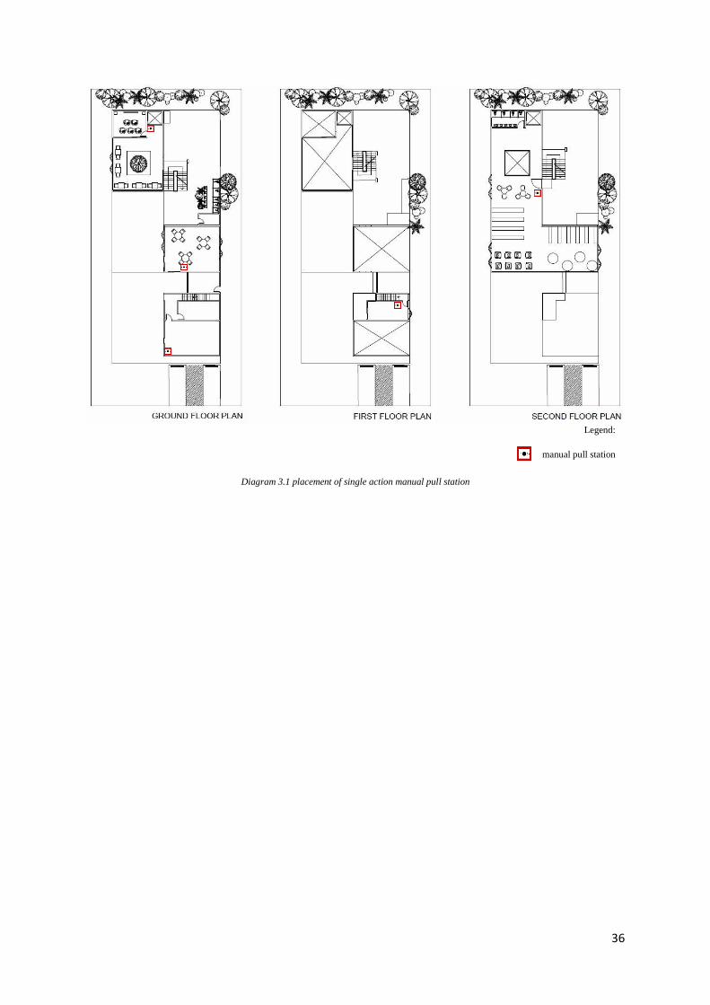
Legend:
manual pull station
Diagram 3.1 placement of single action manual pull station
37
D. Fire Alarm – Two-stage Signal Indicator Alarm
Fire alarm systems are designed to alert the occupants of a building of an outbreak of
fire so that appropriate fire fighting action can be taken before the situation gets out of
hand. The danger of a fire outbreak should never be underestimated as they can bring
serious havoc.
There are two types of fire alarm systems currently used in buildings:
Single system
Two-stage system
The elderly care centre will be deployed with a two-stage system to reduce the
possibility of false alarms.
Operation of Two-stage Alarm System:
In a two-stage alarm, a coded alert will go off to first warn the staff of the fire. The
staff will then inspect and activate the alarm signal if there is a real fire outbreak.
However, the alarm signal will still go off accordingly after a predetermine period. On
the other hand, the staff can stop the coded alert signal and reset the system if it is
proved to be a false alarm. Two-stage system is used as a general alarm will cause
unnecessary distress to the elderlies as evacuation of the elderlies is difficult and may
cause them physical harm.
Also, on the grounds of elderlies with impaired hearing abilities, the alarm system
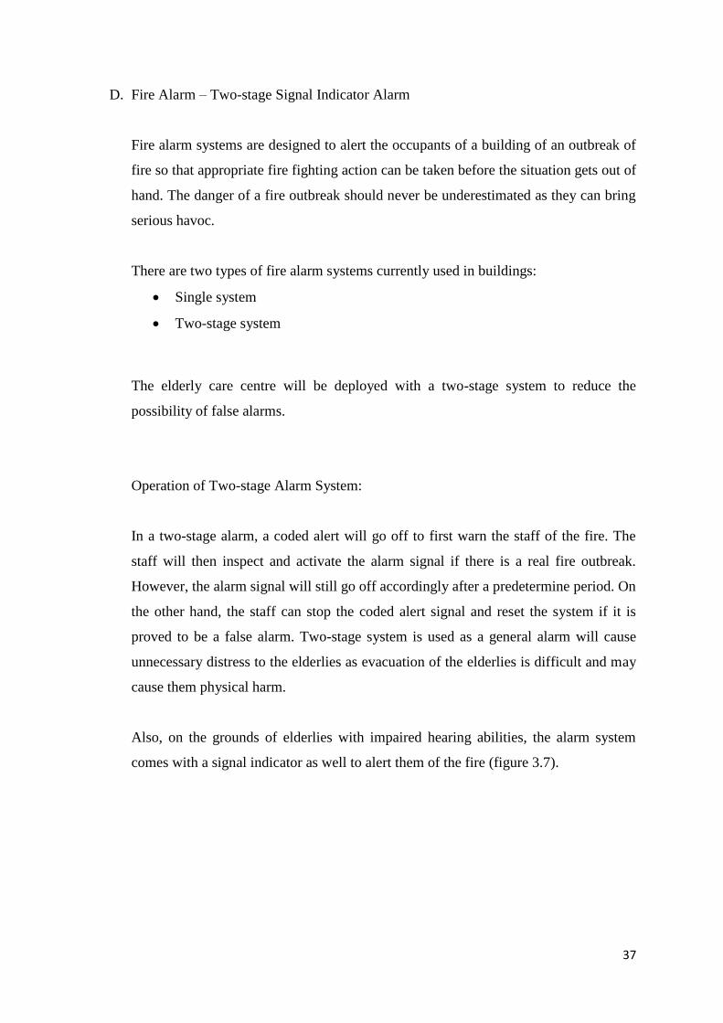
comes with a signal indicator as well to alert them of the fire (figure 3.7).
38
signal indicator
speaker
Figure 3.7 signal indicator alarm components Figure 3.8 fire alarm icon
dimension: 60*117*46mm alarm sound: >= 100dB
flash period: <= 1.5s
flash intensity: >= 1.2WS ambient temperature: -10℃ - +55℃
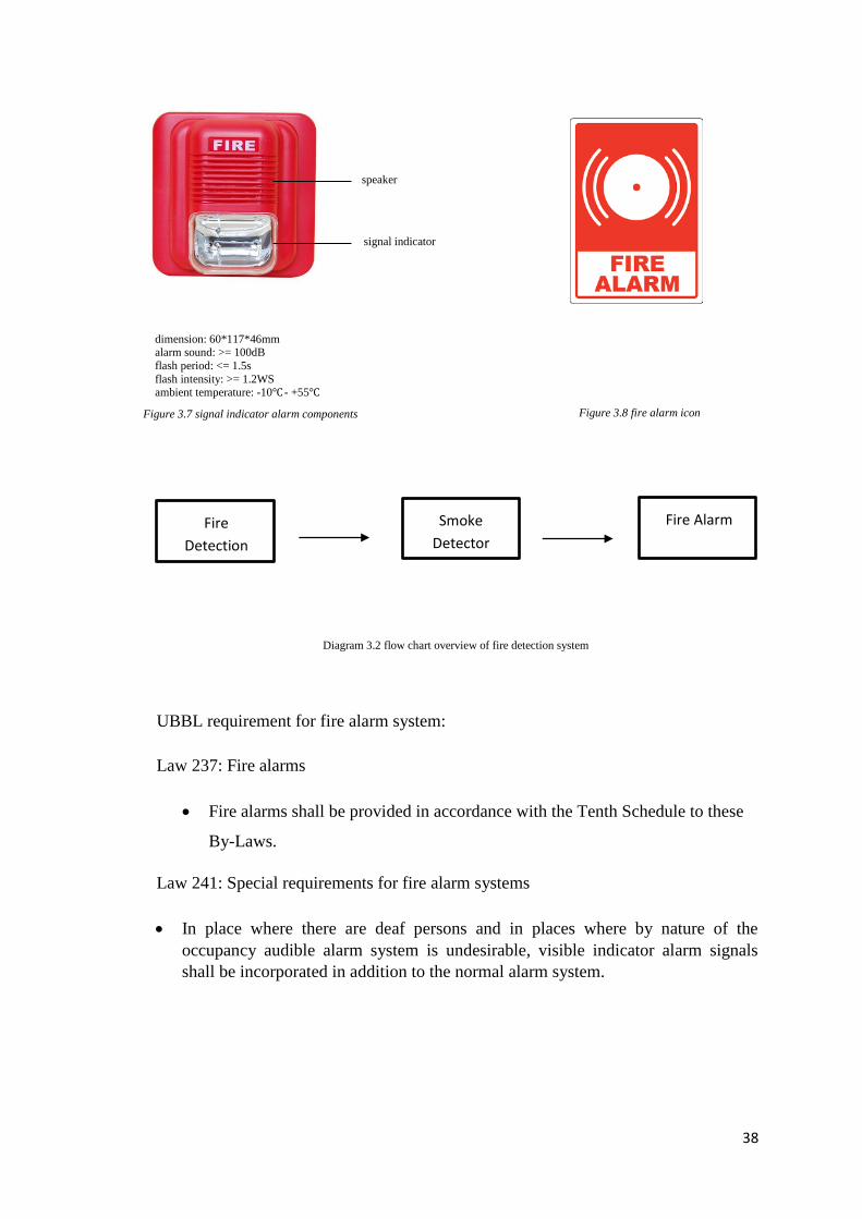
Smoke
Detector
Fire Alarm
Diagram 3.2 flow chart overview of fire detection system
UBBL requirement for fire alarm system:
Law 237: Fire alarms
Fire alarms shall be provided in accordance with the Tenth Schedule to these
By-Laws.
Law 241: Special requirements for fire alarm systems
In place where there are deaf persons and in places where by nature of the
occupancy audible alarm system is undesirable, visible indicator alarm signals
shall be incorporated in addition to the normal alarm system.
Fire
Detection
39
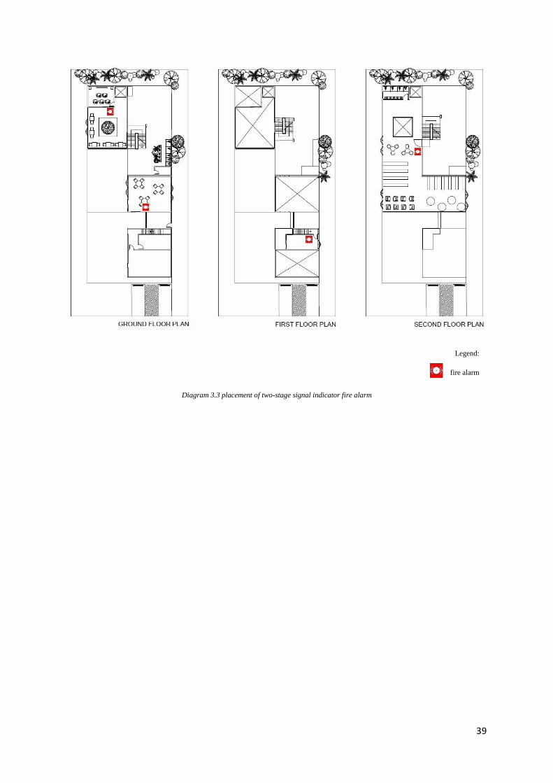
Legend:
fire alarm
Diagram 3.3 placement of two-stage signal indicator fire alarm
40
Table 3.0 type of portable fire extinguisher
3.3.2 Extinguishing Systems
A. Portable Fire Extinguisher
I. Introduction & Function
A fire extinguisher is an equipment used in emergency to contain or extinguish small fire
manually. It is however, unsuitable and unintended for use on a large-scale fire, such as one
that reaches the ceiling or endanger the occupants. Per Port Washington Fire Department,
portable fire extinguishers can save lives and property by putting out a small fire or
controlling it until the arrival of fire department. They are usually sited in prominent
positions on exit routes and are visible from all directions.
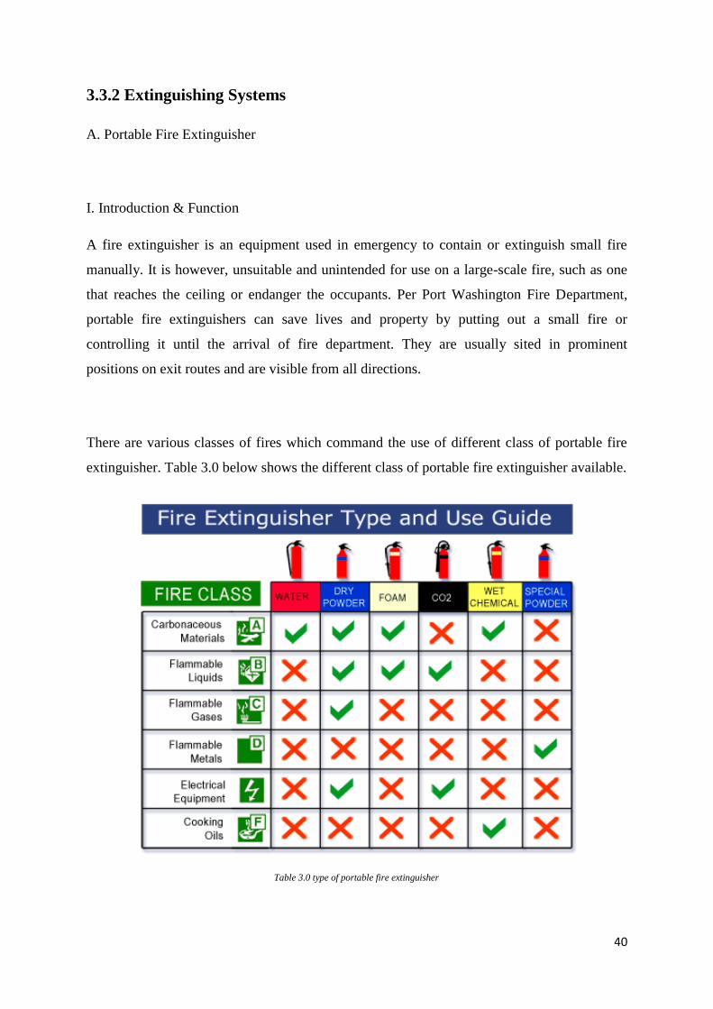
There are various classes of fires which command the use of different class of portable fire
extinguisher. Table 3.0 below shows the different class of portable fire extinguisher available.
41
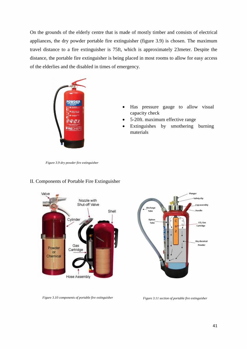
Figure 3.9 dry powder fire extinguisher
Has pressure gauge to allow visual
capacity check
5-20ft. maximum effective range
Extinguishes by smothering burning
materials
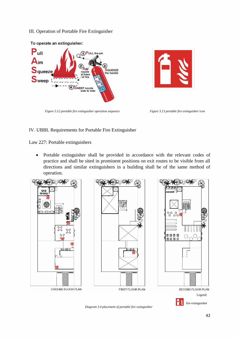
Figure 3.10 components of portable fire extinguisher Figure 3.11 section of portable fire extinguisher
On the grounds of the elderly centre that is made of mostly timber and consists of electrical
appliances, the dry powder portable fire extinguisher (figure 3.9) is chosen. The maximum
travel distance to a fire extinguisher is 75ft, which is approximately 23meter. Despite the
distance, the portable fire extinguisher is being placed in most rooms to allow for easy access
of the elderlies and the disabled in times of emergency.
II. Components of Portable Fire Extinguisher
42
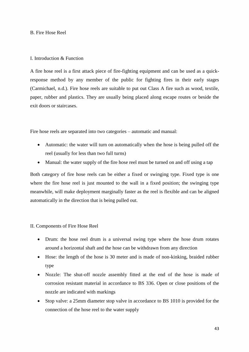
Figure 3.12 portable fire extinguisher operation sequence Figure 3.13 portable fire extinguisher icon
Legend:
fire extinguisher Diagram 3.4 placement of portable fire extinguisher
III. Operation of Portable Fire Extinguisher
IV. UBBL Requirements for Portable Fire Extinguisher
Law 227: Portable extinguishers
Portable extinguisher shall be provided in accordance with the relevant codes of
practice and shall be sited in prominent positions on exit routes to be visible from all
directions and similar extinguishers in a building shall be of the same method of
operation.
43
B. Fire Hose Reel
I. Introduction & Function
A fire hose reel is a first attack piece of fire-fighting equipment and can be used as a quick-
response method by any member of the public for fighting fires in their early stages
(Carmichael, n.d.). Fire hose reels are suitable to put out Class A fire such as wood, textile,
paper, rubber and plastics. They are usually being placed along escape routes or beside the
exit doors or staircases.
Fire hose reels are separated into two categories – automatic and manual:
Automatic: the water will turn on automatically when the hose is being pulled off the
reel (usually for less than two full turns)
Manual: the water supply of the fire hose reel must be turned on and off using a tap
Both category of fire hose reels can be either a fixed or swinging type. Fixed type is one
where the fire hose reel is just mounted to the wall in a fixed position; the swinging type
meanwhile, will make deployment marginally faster as the reel is flexible and can be aligned
automatically in the direction that is being pulled out.
II. Components of Fire Hose Reel
Drum: the hose reel drum is a universal swing type where the hose drum rotates
around a horizontal shaft and the hose can be withdrawn from any direction
Hose: the length of the hose is 30 meter and is made of non-kinking, braided rubber
type
Nozzle: The shut-off nozzle assembly fitted at the end of the hose is made of
corrosion resistant material in accordance to BS 336. Open or close positions of the
nozzle are indicated with markings
Stop valve: a 25mm diameter stop valve in accordance to BS 1010 is provided for the
connection of the hose reel to the water supply
44
pipe painted with primer
& finished
with red paint
rubber hose (pr EN 694) length: 30m/800sqm
diameter: 25mm
Diagram 3.5 discharge flow rate and throw length
6 meter
30 l/min
nozzle • jet and spray adjustable type
• 8mm diameter
Figure 3.14 fire hose reel components
The pipework is 50mm diameter and the pipe feed to individual hose is not less than 25mm
diameter. The pipework for above ground uses minimum galvanised steel medium grade
(Class B); whereas the underground pipework uses minimum heavy grade (Class C).
III. Operation of Fire Hose Reel
The operation of fire hose reels is all very similar as below:
1. Ensure the nozzle or jet is in the closed position
2. Turn on the main valve (some will not let the nozzle out until this is done)
3. Reel out the hose, towards the fire
4. Open the nozzle or valve and direct the stream of water at the fire from a safe distance
(“Fire Extinguishers, Hose Reels and Fire Blankets”, n.d.)
IV. UBBL Requirements for Fire Hose Reel
Law 225: Detecting and extinguishing fire
Every building shall be provided with means of detecting and extinguishing fire and
with fire alarms together with illuminated exit signs in accordance with the
requirements as specified in the Tenth Schedule to these By-laws.
45
Legend:
fire hose reel
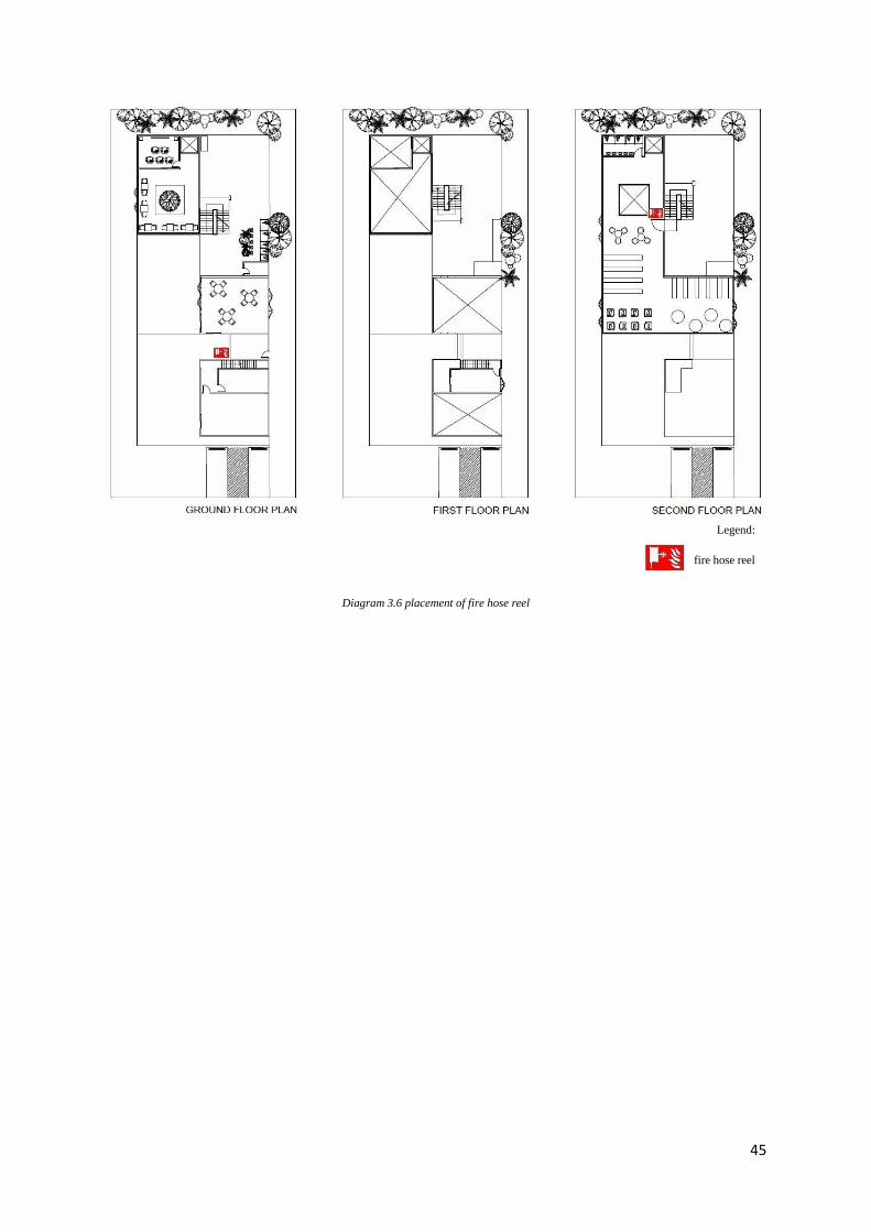
Diagram 3.6 placement of fire hose reel
46
Figure 3.16 dry riser outlet
Figure 3.15 dry riser inlet
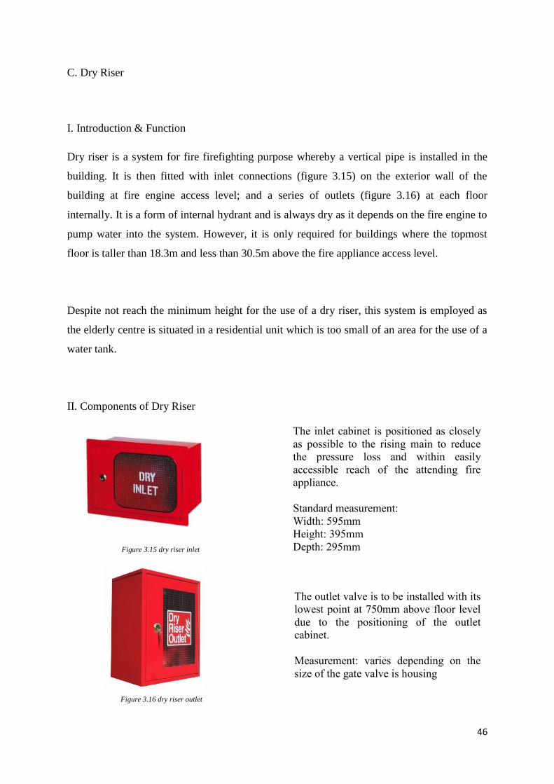
C. Dry Riser
I. Introduction & Function
Dry riser is a system for fire firefighting purpose whereby a vertical pipe is installed in the
building. It is then fitted with inlet connections (figure 3.15) on the exterior wall of the
building at fire engine access level; and a series of outlets (figure 3.16) at each floor
internally. It is a form of internal hydrant and is always dry as it depends on the fire engine to
pump water into the system. However, it is only required for buildings where the topmost
floor is taller than 18.3m and less than 30.5m above the fire appliance access level.
Despite not reach the minimum height for the use of a dry riser, this system is employed as
the elderly centre is situated in a residential unit which is too small of an area for the use of a
water tank.
II. Components of Dry Riser
The inlet cabinet is positioned as closely
as possible to the rising main to reduce
the pressure loss and within easily
accessible reach of the attending fire
appliance.
Standard measurement:
Width: 595mm
Height: 395mm
Depth: 295mm
The outlet valve is to be installed with its
lowest point at 750mm above floor level
due to the positioning of the outlet
cabinet.
Measurement: varies depending on the
size of the gate valve is housing
47
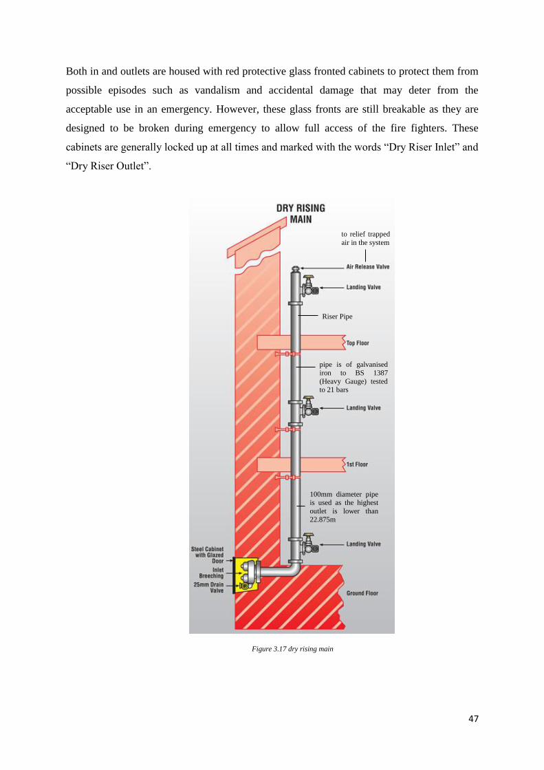
100mm diameter pipe is used as the highest
outlet is lower than
22.875m
to relief trapped
air in the system
pipe is of galvanised
iron to BS 1387
(Heavy Gauge) tested to 21 bars
Riser Pipe
Figure 3.17 dry rising main
Both in and outlets are housed with red protective glass fronted cabinets to protect them from
possible episodes such as vandalism and accidental damage that may deter from the
acceptable use in an emergency. However, these glass fronts are still breakable as they are
designed to be broken during emergency to allow full access of the fire fighters. These
cabinets are generally locked up at all times and marked with the words “Dry Riser Inlet” and
“Dry Riser Outlet”.
48
Legend:
dry riser inlet
dry riser outlet
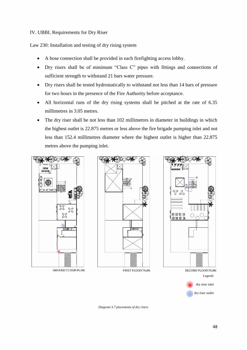
Diagram 3.7 placements of dry risers
IV. UBBL Requirements for Dry Riser
Law 230: Installation and testing of dry rising system
A hose connection shall be provided in each firefighting access lobby.
Dry risers shall be of minimum “Class C” pipes with fittings and connections of
sufficient strength to withstand 21 bars water pressure.
Dry risers shall be tested hydrostatically to withstand not less than 14 bars of pressure
for two hours in the presence of the Fire Authority before acceptance.
All horizontal runs of the dry rising systems shall be pitched at the rate of 6.35
millimetres in 3.05 metres.
The dry riser shall be not less than 102 millimetres in diameter in buildings in which
the highest outlet is 22.875 metres or less above the fire brigade pumping inlet and not
less than 152.4 millimetres diameter where the highest outlet is higher than 22.875
metres above the pumping inlet.
49
Figure 3.18 typical two-way fire hydrant
D. External Fire Hydrant
I. Introduction & Function
An external fire hydrant is intended to provide firemen with water to fight fire in times of
emergency. It provides water to every hydrant outlet by having a system of pipework that is
connected directly to the water supply mains. The water is discharged into the fire engine
from which it is then pumped and sprayed over the fire. Hydrant pumps is provided to
pressurize the fire mains when the water supply is inadequate.
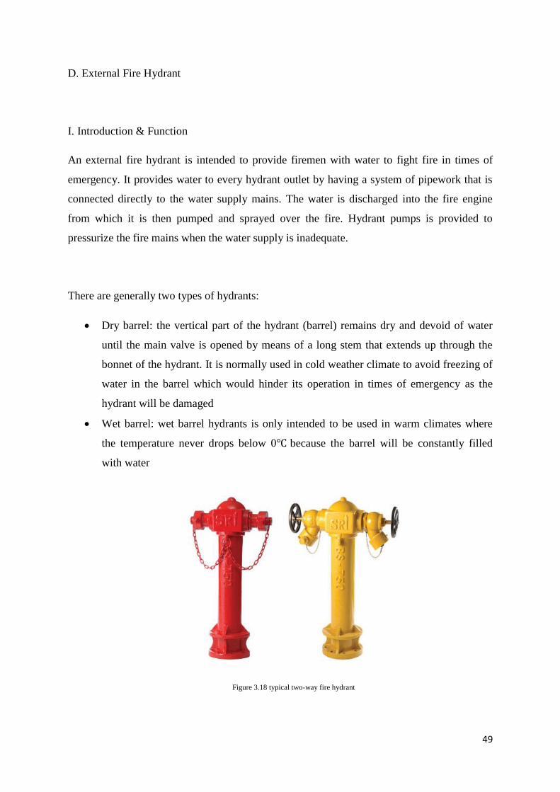
There are generally two types of hydrants:
Dry barrel: the vertical part of the hydrant (barrel) remains dry and devoid of water
until the main valve is opened by means of a long stem that extends up through the
bonnet of the hydrant. It is normally used in cold weather climate to avoid freezing of
water in the barrel which would hinder its operation in times of emergency as the
hydrant will be damaged
Wet barrel: wet barrel hydrants is only intended to be used in warm climates where
the temperature never drops below 0℃ because the barrel will be constantly filled
with water
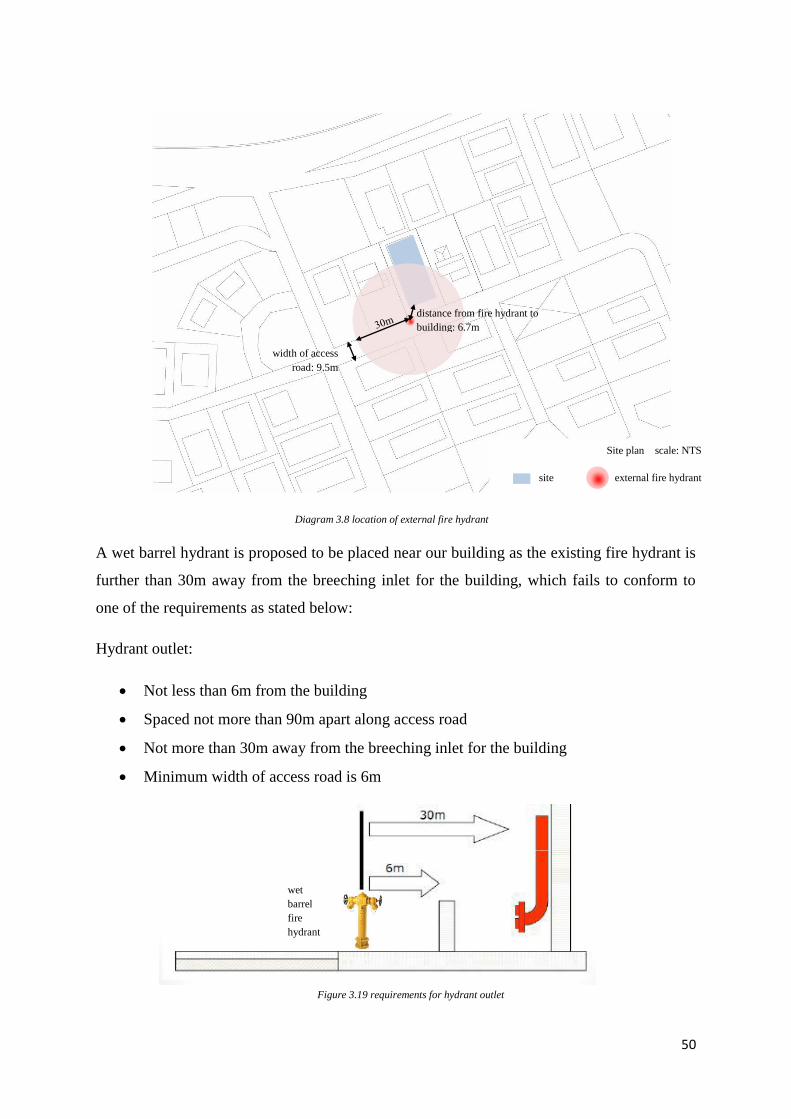
50
Figure 3.19 requirements for hydrant outlet
wet
barrel
fire
hydrant
Diagram 3.8 location of external fire hydrant
A wet barrel hydrant is proposed to be placed near our building as the existing fire hydrant is
further than 30m away from the breeching inlet for the building, which fails to conform to
one of the requirements as stated below:
Hydrant outlet:
Not less than 6m from the building
Spaced not more than 90m apart along access road
Not more than 30m away from the breeching inlet for the building
Minimum width of access road is 6m
Site plan scale: NTS
site external fire hydrant
width of access
road: 9.5m
distance from fire hydrant to
building: 6.7m
51
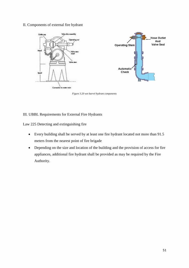
Figure 3.20 wet barrel hydrant components
II. Components of external fire hydrant
III. UBBL Requirements for External Fire Hydrants
Law 225 Detecting and extinguishing fire
Every building shall be served by at least one fire hydrant located not more than 91.5
meters from the nearest point of fire brigade
Depending on the size and location of the building and the provision of access for fire
appliances, additional fire hydrant shall be provided as may be required by the Fire
Authority.
52
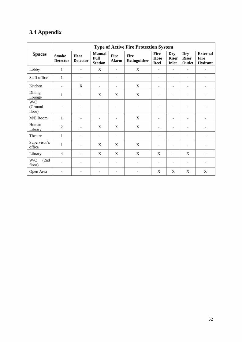
3.4 Appendix
Spaces
Type of Active Fire Protection System
Smoke
Detector
Heat
Detector
Manual
Pull
Station
Fire
Alarm
Fire
Extinguisher
Fire
Hose
Reel
Dry
Riser
Inlet
Dry
Riser
Outlet
External
Fire
Hydrant
Lobby 1 - X - X - - - -
Staff office 1 - - - - - - - -
Kitchen - X - - X - - - -
Dining
Lounge 1 - X X X - - - -
W/C
(Ground
floor)
- - - - - - - - -
M/E Room 1 - - - X - - - -
Human
Library 2 - X X X - - - -
Theatre 1 - - - - - - - -
Supervisor’s
office 1 - X X X - - - -
Library 4 - X X X X - X -
W/C (2nd
floor) - - - - - - - - -
Open Area - - - - - X X X X
53
4.0 Passive Ventilation
4.1 Literature Review
Ventilation of a space is a process by which air is circulated around a space allows fresh air to
enter the space while removing stale air at the same time. It controls the humidity of a certain
space as well as to moderate the internal temperatures. Without proper ventilation within a
space, the space would start to accumulate moisture, dust, carbon dioxide and other pollutants
which can build up if the space heavily used for a long period of time. This tends to lead to a
Sick Building Syndrome (SBS) which causes the user of the space to be unwell. Hence,
ventilation is required for every space to ensure the proper well-being of the users.
Ventilation can come in different ways but passive ventilation is the most sought after as it
does require energy to ensure a comfortable space. Passive ventilation, or also known as
natural ventilation, makes use of natural forces to ventilate a space. One of the most common
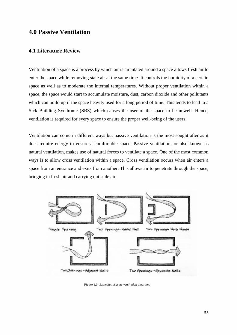
ways is to allow cross ventilation within a space. Cross ventilation occurs when air enters a
space from an entrance and exits from another. This allows air to penetrate through the space,
bringing in fresh air and carrying out stale air.
Figure 4.0: Examples of cross ventilation diagrams
54
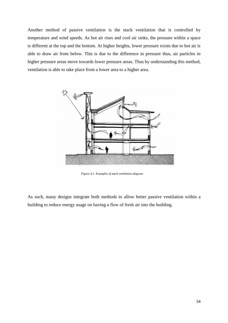
Another method of passive ventilation is the stack ventilation that is controlled by
temperature and wind speeds. As hot air rises and cool air sinks, the pressure within a space
is different at the top and the bottom. At higher heights, lower pressure exists due to hot air is
able to draw air from below. This is due to the difference in pressure thus, air particles in
higher pressure areas move towards lower pressure areas. Thus by understanding this method,
ventilation is able to take place from a lower area to a higher area.
As such, many designs integrate both methods to allow better passive ventilation within a
building to reduce energy usage on having a flow of fresh air into the building.
Figure 4.1: Examples of stack ventilation diagram
55
4.2 Introduction for Passive Ventilation within the Centre
The elderly care centre building comprises of 3 stories with two adjacent buildings on its east
and west while the main winds originate from the northeast and southwest direction. As such,
the parts of the building are exposed to the prevailing winds while certain areas are wind
shadowed by the adjacent buildings. As such, the building is designed to accommodate an air
well that promotes stack ventilation and the use of cross ventilation throughout the spaces.
This ensures that spaces are well ventilated and provide a suitable temperature for the elderly.
4.3 Openings for Ventilation within Spaces
4.3.1 Rooms within an Elderly Care Centre
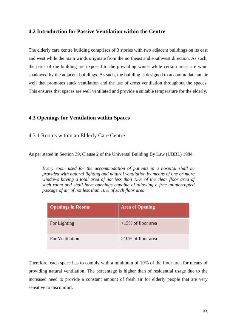
As per stated in Section 39, Clause 2 of the Universal Building By Law (UBBL) 1984:
Therefore, each space has to comply with a minimum of 10% of the floor area for means of
providing natural ventilation. The percentage is higher than of residential usage due to the
increased need to provide a constant amount of fresh air for elderly people that are very
sensitive to discomfort.
Openings in Rooms Area of Opening
For Lighting >15% of floor area
For Ventilation >10% of floor area
Every room used for the accommodation of patients in a hospital shall be
provided with natural lighting and natural ventilation by means of one or more
windows having a total area of not less than 15% of the clear floor area of
such room and shall have openings capable of allowing a free uninterrupted
passage of air of not less than 10% of such floor area.
56
A
B
C
Ground Floor Plan
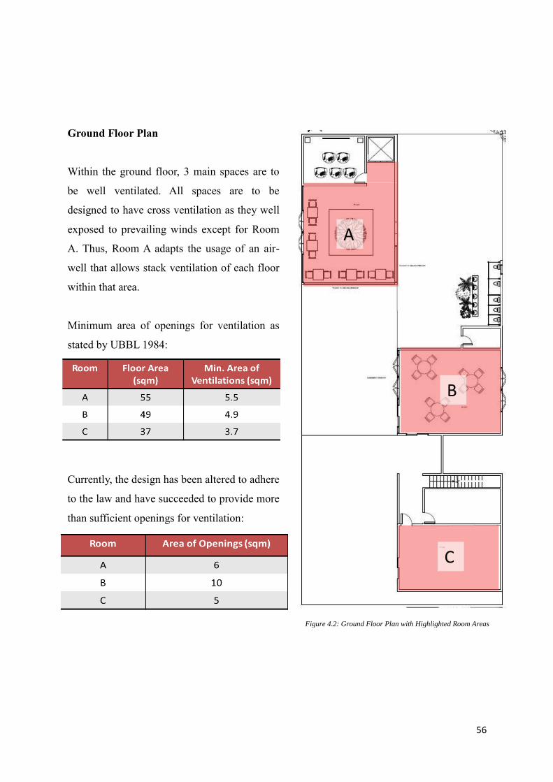
Within the ground floor, 3 main spaces are to
be well ventilated. All spaces are to be
designed to have cross ventilation as they well
exposed to prevailing winds except for Room
A. Thus, Room A adapts the usage of an air-
well that allows stack ventilation of each floor
within that area.
Minimum area of openings for ventilation as
stated by UBBL 1984:
Currently, the design has been altered to adhere
to the law and have succeeded to provide more
than sufficient openings for ventilation:
Figure 4.2: Ground Floor Plan with Highlighted Room Areas
57
First Floor Plan
The first floor consists of only a very small floor
area as compared to the building with only one
space taken into consideration for ventilation as
the other spaces are double volumes of existing
spaces from the ground floor.
Minimum area of openings for ventilation as
stated by UBBL 1984:
Currently, the design has been altered to adhere to
the law and have succeeded to provide more than
sufficient openings for ventilation:
D
Figure 4.3: First Floor Plan with Highlighted Room Areas
58
Second Floor Plan
The second floor consists of a very large floor area
that is mechanically ventilated with an air
conditioner. However, due to the sensitivity of
elderly people, natural ventilation has to be
provided as well to ensure comfort and alternative
ventilation if the mechanical system were to fail.
Minimum area of openings for ventilation as stated
by UBBL 1984:
Currently, the design has been altered to adhere to
the law and have succeeded to provide more than
sufficient openings for ventilation:
E
Figure 4.4: Second Floor Plan with Highlighted Room Areas
59
4.3.2 Washrooms within an Elderly Care Centre
As per stated in Section 39, Clause 4 of the Universal Building By Law (UBBL) 1984:
Therefore, each washroom has to comply with having a 0.2 sqm of opening for ventilation for
each water closet, urinal and bathroom. This ratio is to ensure proper ventilation within each
washroom to allow the removal of stale and unpleasant smell as well as to ensure a dry and
well-kept washroom.
Openings in Water Closet Area of Opening
For Lighting & Ventilation 0.2 sqm per w/c, urinal
Every water-closet, latrine, urinal of bathroom shall be provided with
natural lighting and natural lighting and natural ventilation by means of
one or more openings having a total area of not less than 0.2 square
metre per water-closet, urinal latrine or bathroom and such openings
shall be capable of allowing a free uninterrupted passage of air.
60
Washroom
Throughout the building, there are 2
washrooms with a total of 9 cubicles.
Currently, the design has succeeded to
provide more than sufficient openings for
ventilation:
Figure 4.5: Highlighted location of toilets in ground floor plan (right) and second floor plan (left)
61
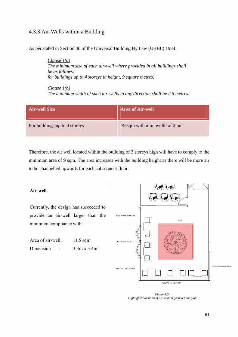
4.3.3 Air-Wells within a Building
As per stated in Section 40 of the Universal Building By Law (UBBL) 1984:
Therefore, the air well located within the building of 3 storeys high will have to comply to the
minimum area of 9 sqm. The area increases with the building height as there will be more air
to be channelled upwards for each subsequent floor.
Air-well
Current
Area of air-well = 11.5 sqm
Dimension = 3.3m x 3.4m
Air-well Size Area of Air-well
For buildings up to 4 storeys >9 sqm with min. width of 2.5m
Clause 1(a)
The minimum size of each air-well where provided in all buildings shall
be as follows:
for buildings up to 4 storeys in height, 9 square metres;
Clause 1(b)
The minimum width of such air-wells in any direction shall be 2.5 metres.
Air-well
Currently, the design has succeeded to
provide an air-well larger than the
minimum compliance with:
Area of air-well: 11.5 sqm
Dimension : 3.3m x 3.4m
Figure 4.6: Highlighted location of air-well on ground floor plan
62
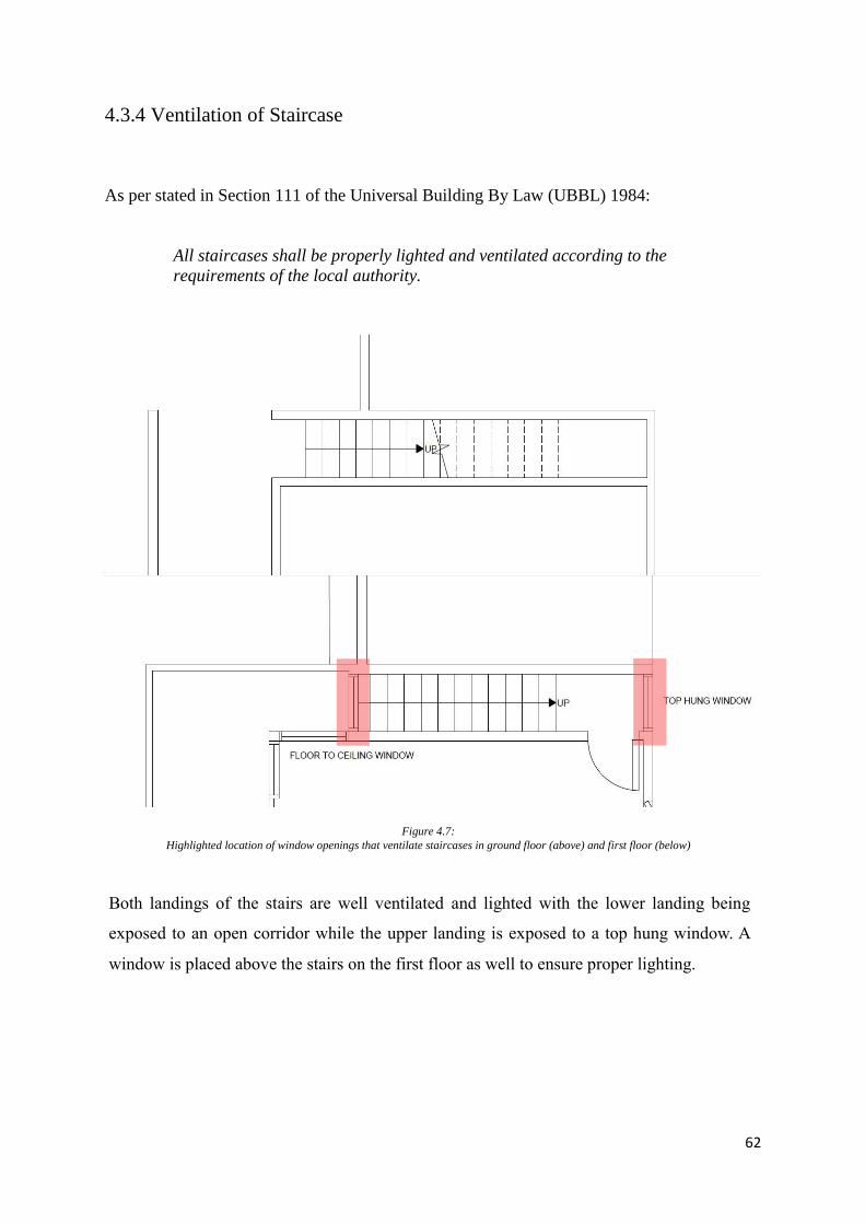
4.3.4 Ventilation of Staircase
As per stated in Section 111 of the Universal Building By Law (UBBL) 1984:
All staircases shall be properly lighted and ventilated according to the
requirements of the local authority.
Both landings of the stairs are well ventilated and lighted with the lower landing being
exposed to an open corridor while the upper landing is exposed to a top hung window. A
window is placed above the stairs on the first floor as well to ensure proper lighting.
Figure 4.7:
Highlighted location of window openings that ventilate staircases in ground floor (above) and first floor (below)
63
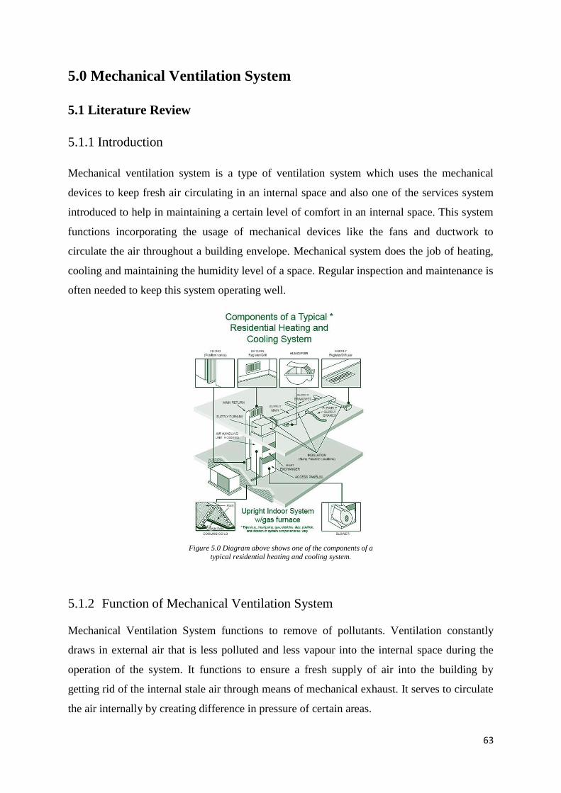
5.0 Mechanical Ventilation System
5.1 Literature Review
5.1.1 Introduction
Mechanical ventilation system is a type of ventilation system which uses the mechanical
devices to keep fresh air circulating in an internal space and also one of the services system
introduced to help in maintaining a certain level of comfort in an internal space. This system
functions incorporating the usage of mechanical devices like the fans and ductwork to
circulate the air throughout a building envelope. Mechanical system does the job of heating,
cooling and maintaining the humidity level of a space. Regular inspection and maintenance is
often needed to keep this system operating well.
Figure 5.0 Diagram above shows one of the components of a typical residential heating and cooling system.
5.1.2 Function of Mechanical Ventilation System
Mechanical Ventilation System functions to remove of pollutants. Ventilation constantly
draws in external air that is less polluted and less vapour into the internal space during the
operation of the system. It functions to ensure a fresh supply of air into the building by
getting rid of the internal stale air through means of mechanical exhaust. It serves to circulate
the air internally by creating difference in pressure of certain areas.
64
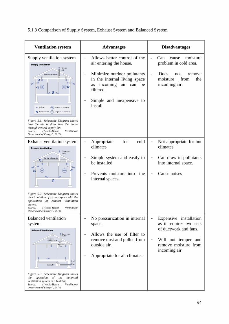
5.1.3 Comparison of Supply System, Exhaust System and Balanced System
Ventilation system Advantages Disadvantages
Supply ventilation system
Figure 5.1: Schematic Diagram shows
how the air is drew into the house
through central supply fan. Source: (“whole-House Ventilation/
Department of Energy”, 2016)
- Allows better control of the
air entering the house.
- Minimize outdoor pollutants
in the internal living space
as incoming air can be
filtered.
- Simple and inexpensive to
install
- Can cause moisture
problem in cold area.
- Does not remove
moisture from the
incoming air.
Exhaust ventilation system
Figure 5.2: Schematic Diagram shows the circulation of air in a space with the
application of exhaust ventilation
system. Source: (“whole-House Ventilation/
Department of Energy”, 2016)
- Appropriate for cold
climates
- Simple system and easily to
be installed
- Prevents moisture into the
internal spaces.
- Not appropriate for hot
climates
- Can draw in pollutants
into internal space.
- Cause noises
Balanced ventilation
system
Figure 5.3: Schematic Diagram shows
the operation of the balanced
ventilation system in a building. Source: (“whole-House Ventilation/
Department of Energy”, 2016)
- No pressurization in internal
space.
- Allows the use of filter to
remove dust and pollen from
outside air.
- Appropriate for all climates
- Expensive installation
as it requires two sets
of ductwork and fans.
- Will not temper and
remove moisture from
incoming air
65
5.2 Operation System of Mechanical Ventilation
5.2.1 Introduction
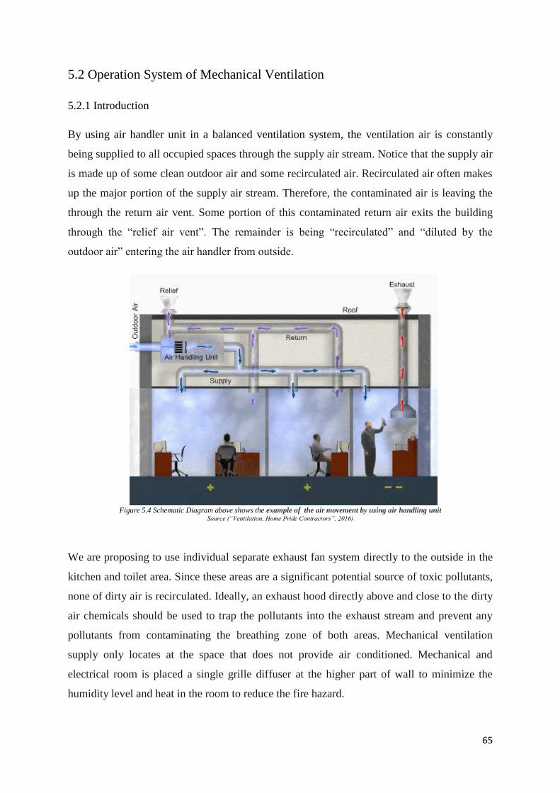
By using air handler unit in a balanced ventilation system, the ventilation air is constantly
being supplied to all occupied spaces through the supply air stream. Notice that the supply air
is made up of some clean outdoor air and some recirculated air. Recirculated air often makes
up the major portion of the supply air stream. Therefore, the contaminated air is leaving the
through the return air vent. Some portion of this contaminated return air exits the building
through the “relief air vent”. The remainder is being “recirculated” and “diluted by the
outdoor air” entering the air handler from outside.
Figure 5.4 Schematic Diagram above shows the example of the air movement by using air handling unit
Source (“Ventilation, Home Pride Contractors”, 2016)
We are proposing to use individual separate exhaust fan system directly to the outside in the
kitchen and toilet area. Since these areas are a significant potential source of toxic pollutants,
none of dirty air is recirculated. Ideally, an exhaust hood directly above and close to the dirty
air chemicals should be used to trap the pollutants into the exhaust stream and prevent any
pollutants from contaminating the breathing zone of both areas. Mechanical ventilation
supply only locates at the space that does not provide air conditioned. Mechanical and
electrical room is placed a single grille diffuser at the higher part of wall to minimize the
humidity level and heat in the room to reduce the fire hazard.
66
5.2.2 Operation of Central Fan Integrated System and Its Components
5.2.2.1 Air Handler
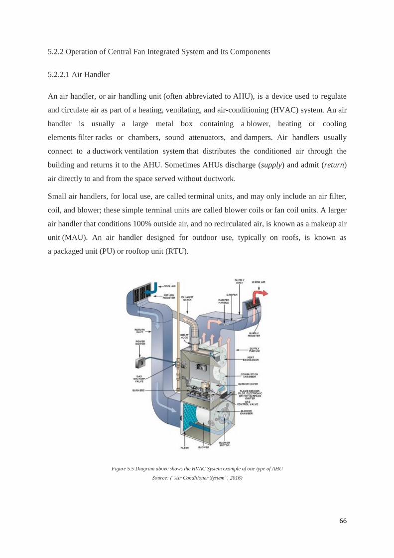
An air handler, or air handling unit (often abbreviated to AHU), is a device used to regulate
and circulate air as part of a heating, ventilating, and air-conditioning (HVAC) system. An air
handler is usually a large metal box containing a blower, heating or cooling
elements filter racks or chambers, sound attenuators, and dampers. Air handlers usually
connect to a ductwork ventilation system that distributes the conditioned air through the
building and returns it to the AHU. Sometimes AHUs discharge (supply) and admit (return)
air directly to and from the space served without ductwork.
Small air handlers, for local use, are called terminal units, and may only include an air filter,
coil, and blower; these simple terminal units are called blower coils or fan coil units. A larger
air handler that conditions 100% outside air, and no recirculated air, is known as a makeup air
unit (MAU). An air handler designed for outdoor use, typically on roofs, is known as
a packaged unit (PU) or rooftop unit (RTU).
Figure 5.5 Diagram above shows the HVAC System example of one type of AHU
Source: (“Air Conditioner System”, 2016)
67
5.2.2.2 Fan
Fan serves the purpose of removing hot, humid and polluted air, it's often used to bring in
outdoor air to encourage ventilation and cool the internal spaces of a building. It's one of the
important component involved in a mechanical ventilation system in order to complete the air
circulation cycle of a system. Besides that, fan helps to keep the fresh air circulating within a
space.
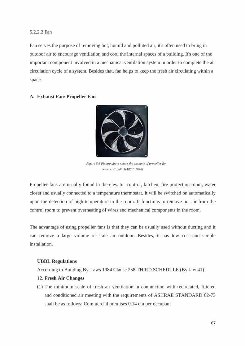
A. Exhaust Fan/ Propeller Fan
Figure 5.6 Picture above shows the example of propeller fan
Source: (“IndiaMART”, 2016)
Propeller fans are usually found in the elevator control, kitchen, fire protection room, water
closet and usually connected to a temperature thermostat. It will be switched on automatically
upon the detection of high temperature in the room. It functions to remove hot air from the
control room to prevent overheating of wires and mechanical components in the room.
The advantage of using propeller fans is that they can be usually used without ducting and it
can remove a large volume of stale air outdoor. Besides, it has low cost and simple
installation.
UBBL Regulations
According to Building By-Laws 1984 Clause 258 THIRD SCHEDULE (By-law 41)
12. Fresh Air Changes
(1) The minimum scale of fresh air ventilation in conjunction with recirclated, filtered
and conditioned air meeting with the requirements of ASHRAE STANDARD 62-73
shall be as follows: Commercial premises 0.14 cm per occupant
68
(2) The minimum scale of fresh air ventilation in conjunction with the mechanical
ventilation systems shall be as follows: Commercial premises (excluding laundry and
boiler houses) 0.28 cm3 per occupant
5.2.2.3 Ductworks
Ductworks serve to channel air into a room or out from a room. It comes in different shapes
and sizes which will also affect the efficiency and sustainability. They are usually made from
aluminum, copper and galvanized materials and often connected to the central supply fan or
central exhaust fan of the mechanical ventilation system.
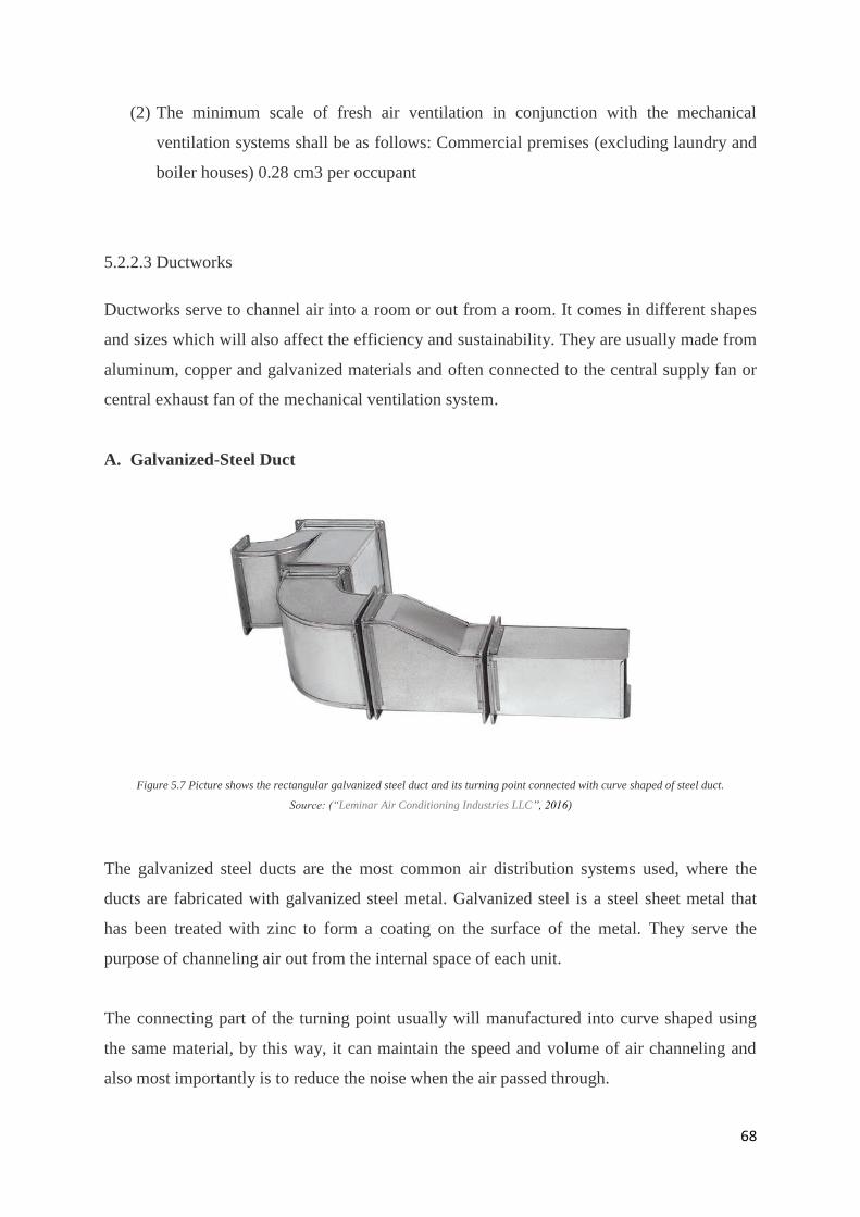
A. Galvanized-Steel Duct
Figure 5.7 Picture shows the rectangular galvanized steel duct and its turning point connected with curve shaped of steel duct.
Source: (“Leminar Air Conditioning Industries LLC”, 2016)
The galvanized steel ducts are the most common air distribution systems used, where the
ducts are fabricated with galvanized steel metal. Galvanized steel is a steel sheet metal that
has been treated with zinc to form a coating on the surface of the metal. They serve the
purpose of channeling air out from the internal space of each unit.
The connecting part of the turning point usually will manufactured into curve shaped using
the same material, by this way, it can maintain the speed and volume of air channeling and
also most importantly is to reduce the noise when the air passed through.
69
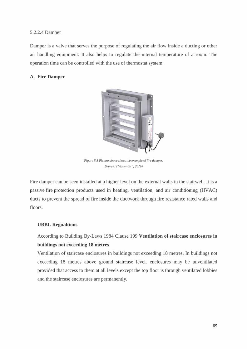
5.2.2.4 Damper
Damper is a valve that serves the purpose of regulating the air flow inside a ducting or other
air handling equipment. It also helps to regulate the internal temperature of a room. The
operation time can be controlled with the use of thermostat system.
A. Fire Damper
Figure 5.8 Picture above shoes the example of fire damper.
Source: (“Actionair”, 2016)
Fire damper can be seen installed at a higher level on the external walls in the stairwell. It is a
passive fire protection products used in heating, ventilation, and air conditioning (HVAC)
ducts to prevent the spread of fire inside the ductwork through fire resistance rated walls and
floors.
UBBL Regualtions
According to Building By-Laws 1984 Clause 199 Ventilation of staircase enclosures in
buildings not exceeding 18 metres
Ventilation of staircase enclosures in buildings not exceeding 18 metres. In buildings not
exceeding 18 metres above ground staircase level. enclosures may be unventilated
provided that access to them at all levels except the top floor is through ventilated lobbies
and the staircase enclosures are permanently.
70
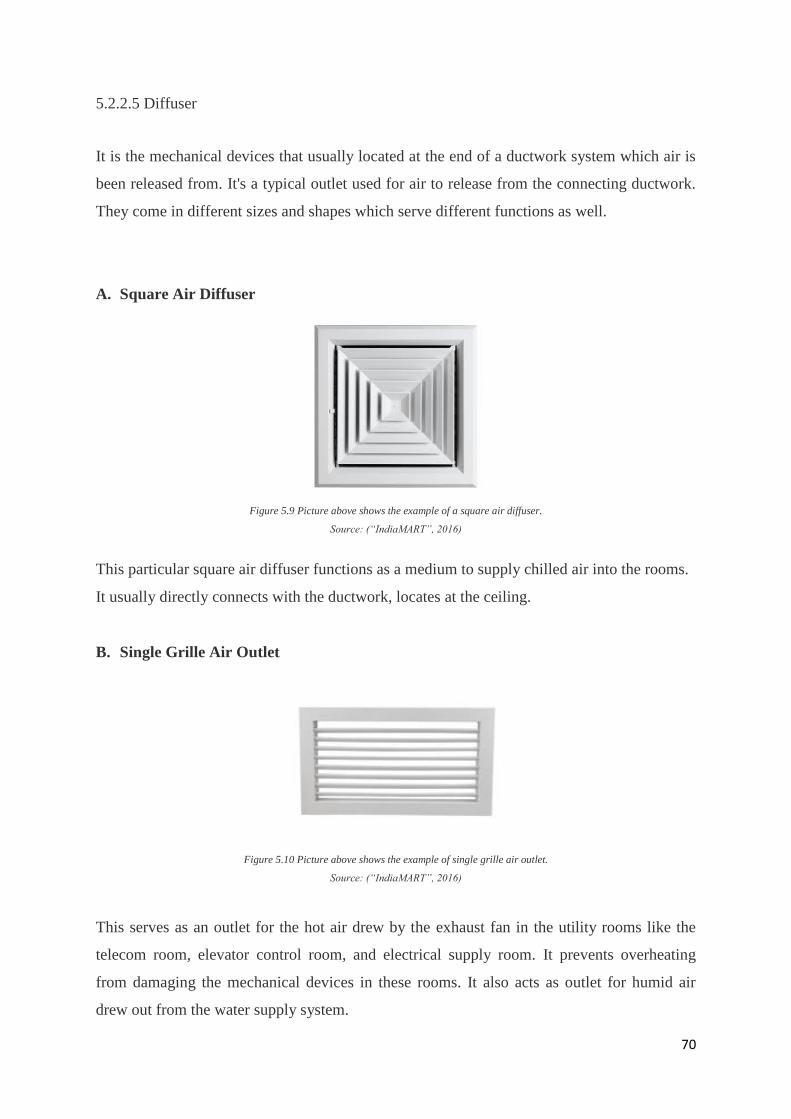
5.2.2.5 Diffuser
It is the mechanical devices that usually located at the end of a ductwork system which air is
been released from. It's a typical outlet used for air to release from the connecting ductwork.
They come in different sizes and shapes which serve different functions as well.
A. Square Air Diffuser
Figure 5.9 Picture above shows the example of a square air diffuser.
Source: (“IndiaMART”, 2016)
This particular square air diffuser functions as a medium to supply chilled air into the rooms.
It usually directly connects with the ductwork, locates at the ceiling.
B. Single Grille Air Outlet
Figure 5.10 Picture above shows the example of single grille air outlet.
Source: (“IndiaMART”, 2016)
This serves as an outlet for the hot air drew by the exhaust fan in the utility rooms like the
telecom room, elevator control room, and electrical supply room. It prevents overheating
from damaging the mechanical devices in these rooms. It also acts as outlet for humid air
drew out from the water supply system.
71
5.2.3 Operation of Systems in Plans and Sections
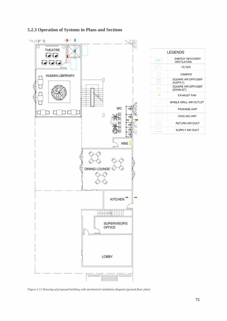
Figure 5.11 Drawing of proposed building with mechanical ventilation diagram (ground floor plan)
72
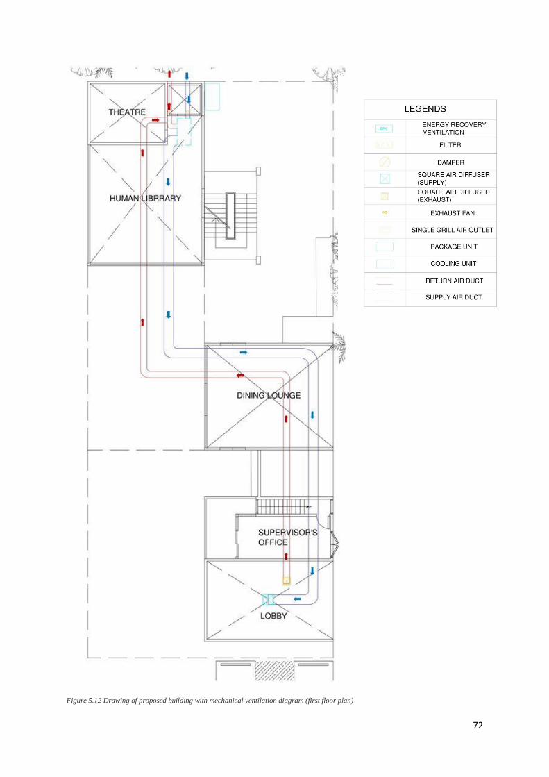
Figure 5.12 Drawing of proposed building with mechanical ventilation diagram (first floor plan)
73
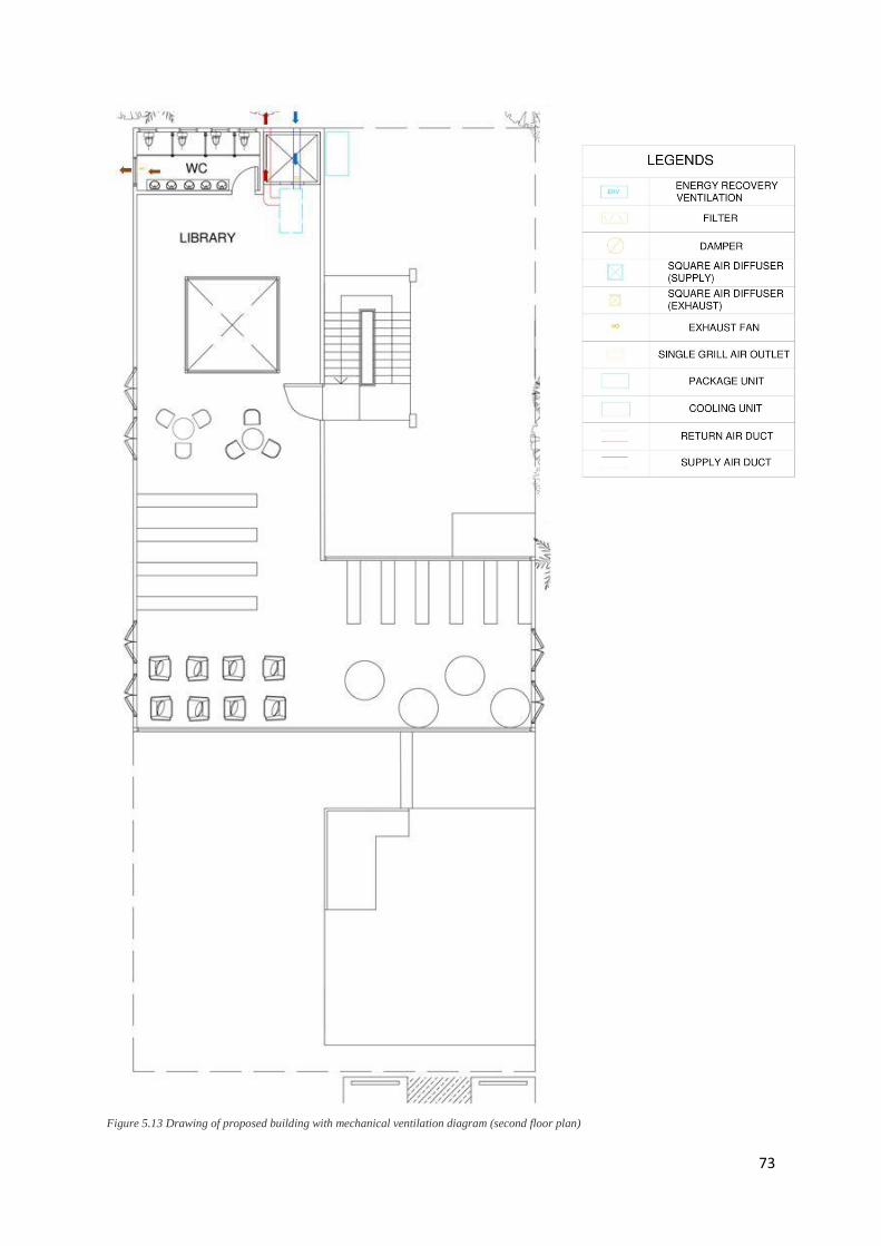
Figure 5.13 Drawing of proposed building with mechanical ventilation diagram (second floor plan)
74
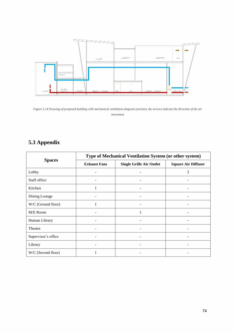
Figure 5.14 Drawing of proposed building with mechanical ventilation diagram (section), the arrows indicate the direction of the air
movement
5.3 Appendix
Spaces Type of Mechanical Ventilation System (or other system)
Exhaust Fans Single Grille Air Outlet Square Air Diffuser
Lobby - - 2
Staff office - - -
Kitchen 1 - -
Dining Lounge - - -
W/C (Ground floor) 1 - -
M/E Room - 1 -
Human Library - - -
Theatre - - -
Supervisor’s office - - -
Library - - -
W/C (Second floor) 1 - -
75
6.0 Air Conditioning System - Packaged Unit
6.1 Literature Review
Packaged unit air conditioning systems are used generally in medium-sized structures such as
commercial lots, restaurants, larger homes and etc. This air conditioning system has a unit
casing that contains all the significant components of an air conditioner such as the
compressor, condenser and condenser coil. It has a cooling capacity range of 3, 5, 7, 10 and
15 tons. It is the intermediate option in between the smaller capacity split air conditioning
system capable of up to only 5 tons and the larger capacity central air conditioning system
capable of extending further than 20 tons.
`
Figure 6.0: Packaged Air Conditioning System Outdoor Unit
There are 2 types of packaged unit systems that use different cooling methods such as the air
cooled systems and water cooled systems. Air cooled systems are more favourable due to the
abundance of atmospheric air as opposed to the lack in supply of water.
This system provides a regular cycle of fresh and clean air to the spaces. As warm air is
transferred back into the return air ducts, it brings along the airborne particles and pollutants
which will be removed through an air filter, thus, cleaning the air which will then be
transferred back to the supply ducts.
The packaged unit system also offers less noise due to the fact that the main unit is
designated to be placed outdoors hence bringing loud operation noise away from the spaces
and its occupants.
76
6.2 Introduction to Packaged Unit System
A packaged unit system was chosen to be used instead of a split system or a central cooling
system because of its intermediate cooling capacity that is suitable for the site which is a
medium sized residential lot with rather large spaces. A split system has a lower cooling
capacity and is more suitable for individualistic residential spaces and smaller sizes while the
central cooling system and its large cooling capacity is more suitable for structures that are
larger and would require more space to contain the units.
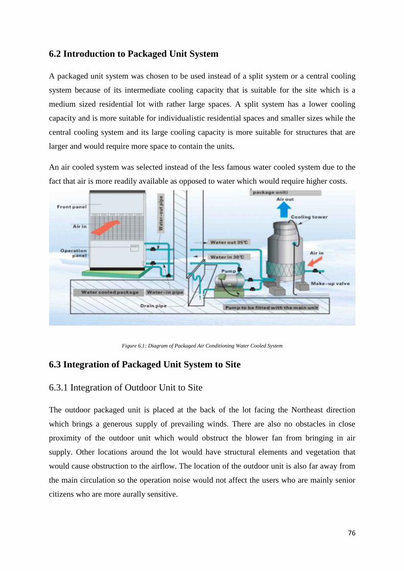
An air cooled system was selected instead of the less famous water cooled system due to the
fact that air is more readily available as opposed to water which would require higher costs.
Figure 6.1: Diagram of Packaged Air Conditioning Water Cooled System
6.3 Integration of Packaged Unit System to Site
6.3.1 Integration of Outdoor Unit to Site
The outdoor packaged unit is placed at the back of the lot facing the Northeast direction
which brings a generous supply of prevailing winds. There are also no obstacles in close
proximity of the outdoor unit which would obstruct the blower fan from bringing in air
supply. Other locations around the lot would have structural elements and vegetation that
would cause obstruction to the airflow. The location of the outdoor unit is also far away from
the main circulation so the operation noise would not affect the users who are mainly senior
citizens who are more aurally sensitive.
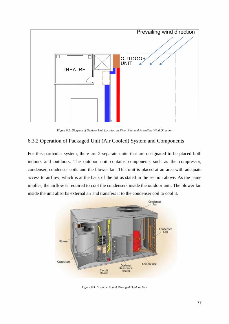
77
Figure 6.2: Diagram of Outdoor Unit Location on Floor Plan and Prevailing Wind Direction
6.3.2 Operation of Packaged Unit (Air Cooled) System and Components
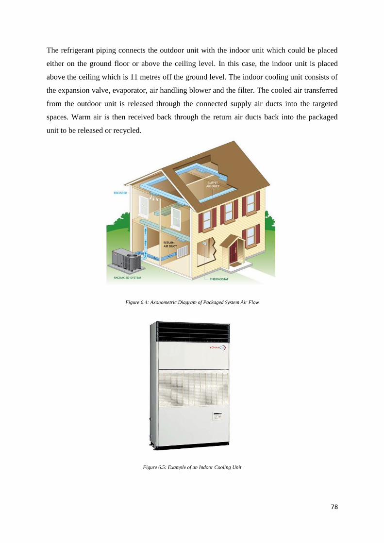
For this particular system, there are 2 separate units that are designated to be placed both
indoors and outdoors. The outdoor unit contains components such as the compressor,
condenser, condenser coils and the blower fan. This unit is placed at an area with adequate
access to airflow, which is at the back of the lot as stated in the section above. As the name
implies, the airflow is required to cool the condensers inside the outdoor unit. The blower fan
inside the unit absorbs external air and transfers it to the condenser coil to cool it.
Figure 6.3: Cross Section of Packaged Outdoor Unit
Prevailing wind direction
78
The refrigerant piping connects the outdoor unit with the indoor unit which could be placed
either on the ground floor or above the ceiling level. In this case, the indoor unit is placed
above the ceiling which is 11 metres off the ground level. The indoor cooling unit consists of
the expansion valve, evaporator, air handling blower and the filter. The cooled air transferred
from the outdoor unit is released through the connected supply air ducts into the targeted
spaces. Warm air is then received back through the return air ducts back into the packaged
unit to be released or recycled.
Figure 6.4: Axonometric Diagram of Packaged System Air Flow
Figure 6.5: Example of an Indoor Cooling Unit
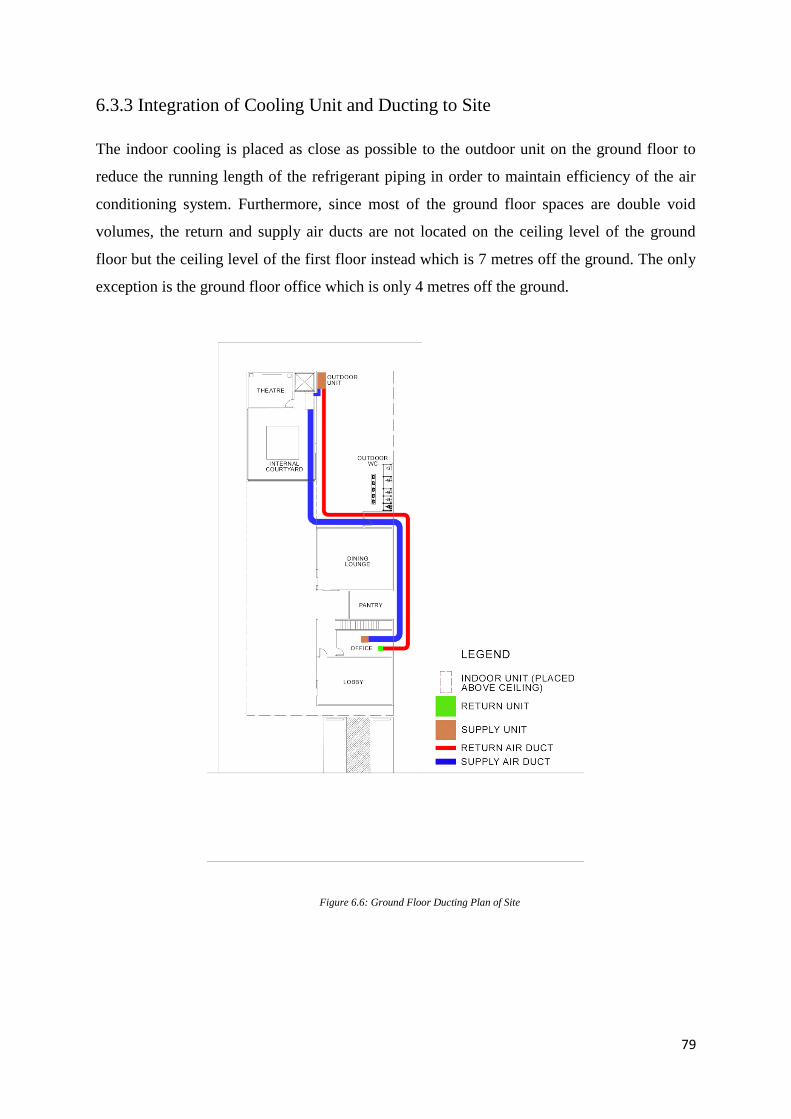
79
6.3.3 Integration of Cooling Unit and Ducting to Site
The indoor cooling is placed as close as possible to the outdoor unit on the ground floor to
reduce the running length of the refrigerant piping in order to maintain efficiency of the air
conditioning system. Furthermore, since most of the ground floor spaces are double void
volumes, the return and supply air ducts are not located on the ceiling level of the ground
floor but the ceiling level of the first floor instead which is 7 metres off the ground. The only
exception is the ground floor office which is only 4 metres off the ground.
Figure 6.6: Ground Floor Ducting Plan of Site
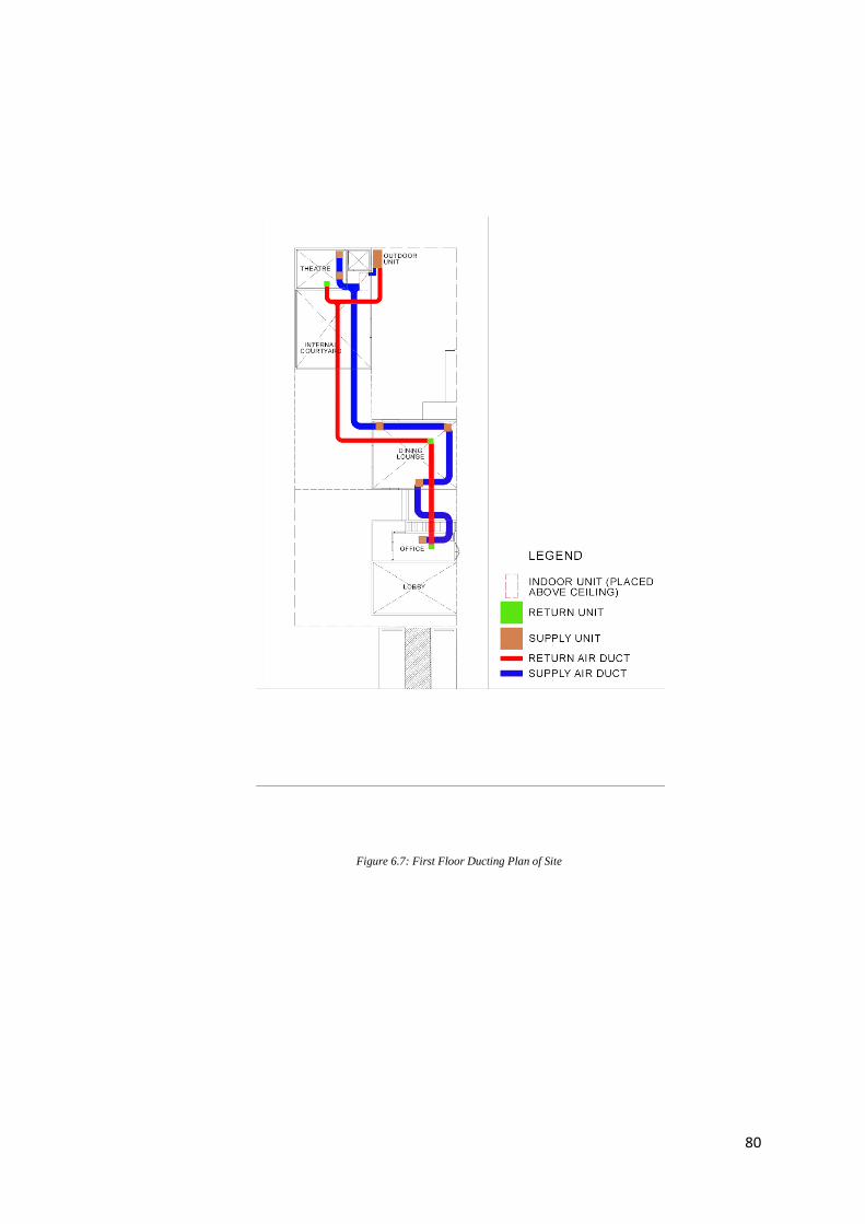
80
Figure 6.7: First Floor Ducting Plan of Site
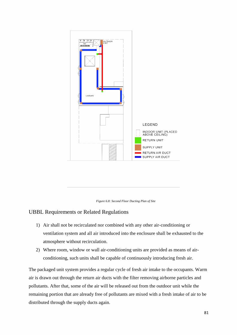
81
Figure 6.8: Second Floor Ducting Plan of Site
UBBL Requirements or Related Regulations
1) Air shall not be recirculated nor combined with any other air-conditioning or
ventilation system and all air introduced into the enclosure shall be exhausted to the
atmosphere without recirculation.
2) Where room, window or wall air-conditioning units are provided as means of air-
conditioning, such units shall be capable of continuously introducing fresh air.
The packaged unit system provides a regular cycle of fresh air intake to the occupants. Warm
air is drawn out through the return air ducts with the filter removing airborne particles and
pollutants. After that, some of the air will be released out from the outdoor unit while the
remaining portion that are already free of pollutants are mixed with a fresh intake of air to be
distributed through the supply ducts again.
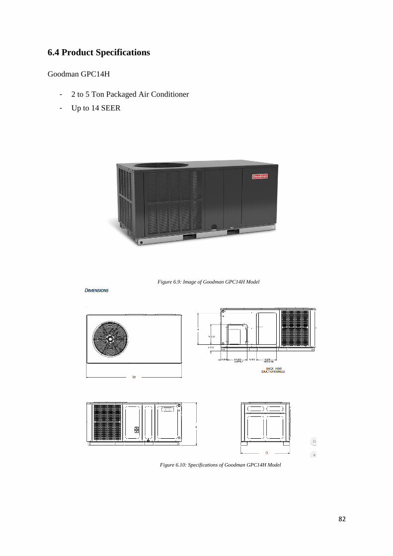
82
6.4 Product Specifications
Goodman GPC14H
- 2 to 5 Ton Packaged Air Conditioner
- Up to 14 SEER
Figure 6.9: Image of Goodman GPC14H Model
Figure 6.10: Specifications of Goodman GPC14H Model
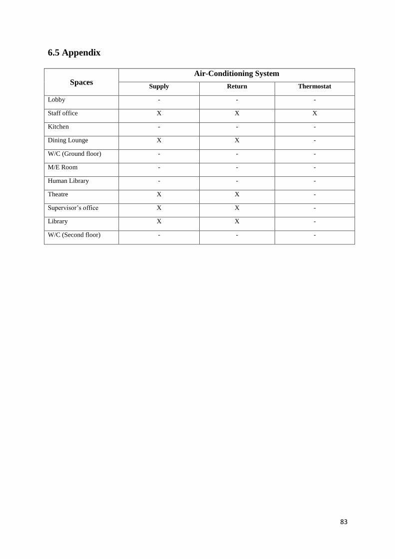
83
6.5 Appendix
Spaces
Air-Conditioning System
Supply Return Thermostat
Lobby - - -
Staff office X X X
Kitchen - - -
Dining Lounge X X -
W/C (Ground floor) - - -
M/E Room - - -
Human Library - - -
Theatre X X -
Supervisor’s office X X -
Library X X -
W/C (Second floor) - - -
84
7.0 Mechanical Transportation System
7.1 Literature Review
The spatial needs and impact of transportation systems have revolutionized building design
and such equipment can only be regarded as an integral part of the normal building service
process. Consequently, requirements and regulations of building services must be anticipated
at an early stage of building design, with heavy consideration of the dependence on other
building services such as mechanical ventilation, air-conditioning system, fire protection
system, means of escape, coordination of installations and long-term maintenance of the
facility. Examples of mechanical transportation include elevators, escalators and travelators.
7.1.1 Elevators
Elevators or lifts are transport devices used to move goods or people, vertically. They are
one of the forms of mechanical transportation which may be found within, around and in
general association with modern buildings and development. Elevators are considered a
requirement in buildings over three storeys, and less if access for the disabled is required in
the design.
An elevator system must provide quick, quiet operation of doors; good floor status and travel
direction indication (both in the cars and at landings); easily operated car and landing call
buttons; smooth, quiet and safe operation of all mechanical equipment under all conditions of
loading; comfortable lighting; reliable emergency and security equipment; and a generally
pleasant car atmosphere.
An ideal performance of an elevator will provide the following:
i. minimum waiting time for a car at any floor level;
ii. comfortable acceleration;
iii. rapid transportation;
iv. smooth, rapid braking;
v. accurate automatic levelling at landings;
vi. rapid loading and unloading at all stop
Apart from passenger-satisfaction service considerations, elevators also have architectural
design impacts which include treating cars and shaftway doors in a manner consistent with
85
the architectural unity of the building. According to Figure 7.0, at least an elevator shall be
provided for non-residential buildings which exceed 4 storeys above or below the main
access level.
Figure 7.0: UBBL By-Law 124. Lifts
Factors affecting installation of elevators include position of the elevators, speeds and
types of elevators. In terms of position or location of elevators, easy means of access should
be provided for all building users – to position lifts in the central lobby with a maximum
walking distance of 45 meters to the lift lobby. Position of elevator should also showcase
useful display of space – advantageous to position the elevator at opposite ends or corners of
building.
Types of elevators include electric lifts, traction elevators, hydraulic elevators, fire-fighting
lifts, observation/panoramic lifts, paternoster and stair lifts, with electric lifts and hydraulic
elevators being the most commonly used. Electric lifts can be categorized into two types –
traction with machine room and machine room-less traction. Traction lifts are raised and
lowered due to friction that transmits force from drive mechanism through cables attached to
or passing under the car which in turn are raised and lowered by a motor-driven traction
sheave.
Figure 7.1: Traction with machine room elevator (left); Machine room-less traction elevator (right)
Uniform Building By-Laws (UBBL)
Part VI – Constructional Requirements
124. Lifts
For all non-residential buildings exceeding 4 storeys above or below the main access level at least one lift
shall be provided.
86
On the other hand, hydraulic elevators are raised and lowered by means of a movable rod
(plunger) rigidly fixed to the bottom of the car. Hydraulic elevators are powered by a piston
that travels inside a cylinder. An electric motor pumps hydraulic oil into the cylinder to move
the piston which will smoothly lift the elevator car. Electric valves are also used to control
the release of the oil for a gentle descent.
7.2 Findings & Analysis of Elevators
7.2.1 Introduction & Function
Before electricity became widely available, some of the earliest lifts were operated by
hydraulic water power. Later on, experiments proved oil to be a more efficient medium, but
with an overall theoretical maximum travel of 21 meters, therefore they are no threat to
electric lifts for higher-rise buildings.
Hydraulic elevators are raised and lowered by means of a movable rod rigidly fixed to the
bottom of the car. They are typically used for low-rise applications of two to eight storeys
and are suitable for goods lifting, for hospitals as well as for old folks’ homes.
Types of hydraulic elevators include conventional plunger-type hydraulic elevators, hole-
less hydraulic elevators and roped hydraulic elevators. Figure 7.2 shows the advantages and
disadvantages of hydraulic elevators.
Advantages of Hydraulic Elevators Disadvantages of Hydraulic Elevators
Capacity for very heavy loads Limited in speed to about 0.75m/s to
maintain adequate standards of control
and comfort
Accuracy in floor levelling Specialist equipment may be needed
during construction to provide a deep
borehole to accommodate the hydraulic
cylinder (depending on the system used)
Smooth ride characteristics
Low-level plant room
No structural loads from winding gear
Pump room can be located up to 10
meters from the shaft
Figure 7.2: Advantages and Disadvantages of Hydraulic Elevators
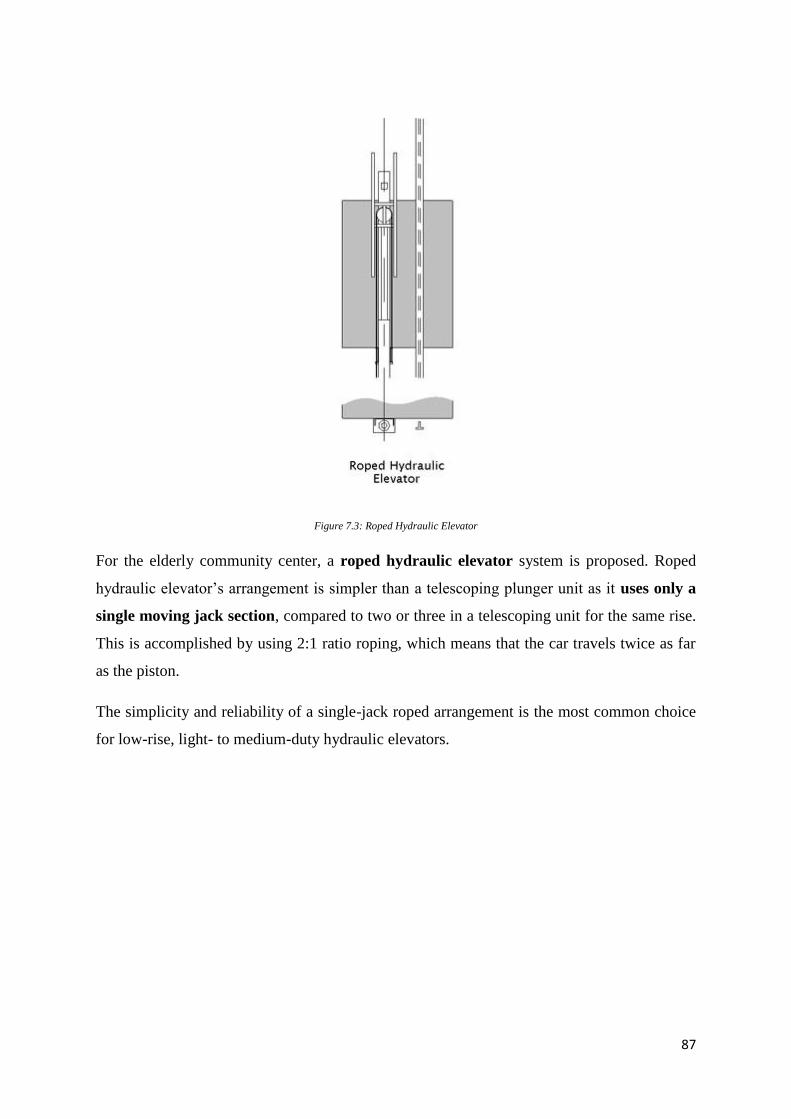
87
Figure 7.3: Roped Hydraulic Elevator
For the elderly community center, a roped hydraulic elevator system is proposed. Roped
hydraulic elevator’s arrangement is simpler than a telescoping plunger unit as it uses only a
single moving jack section, compared to two or three in a telescoping unit for the same rise.
This is accomplished by using 2:1 ratio roping, which means that the car travels twice as far
as the piston.
The simplicity and reliability of a single-jack roped arrangement is the most common choice
for low-rise, light- to medium-duty hydraulic elevators.
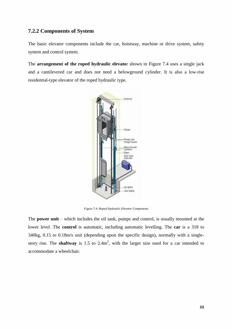
88
7.2.2 Components of System
The basic elevator components include the car, hoistway, machine or drive system, safety
system and control system.
The arrangement of the roped hydraulic elevator shown in Figure 7.4 uses a single jack
and a cantilevered car and does not need a belowground cylinder. It is also a low-rise
residential-type elevator of the roped hydraulic type.
Figure 7.4: Roped Hydraulic Elevator Components
The power unit – which includes the oil tank, pumps and control, is usually mounted at the
lower level. The control is automatic, including automatic levelling. The car is a 318 to
340kg, 0.15 to 0.18m/s unit (depending upon the specific design), normally with a single-
story rise. The shaftway is 1.5 to 2.4m2, with the larger size used for a car intended to
accommodate a wheelchair.
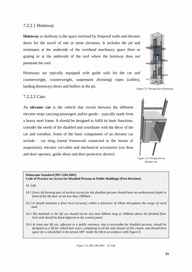
89
7.2.2.1 Hoistway
Hoistway or shaftway is the space enclosed by fireproof walls and elevator
doors for the travel of one or more elevators. It includes the pit and
terminates at the underside of the overhead machinery space floor or
grating or at the underside of the roof where the hoistway does not
penetrate the roof.
Hoistways are typically equipped with guide rails for the car and
counterweight, counterweight, suspension (hoisting) ropes (cables),
landing (hoistway) doors and buffers in the pit.
7.2.2.2 Cars
An elevator car is the vehicle that travels between the different
elevator stops carrying passengers and/or goods – typically made from
a heavy steel frame. It should be designed to fulfil its basic functions,
consider the needs of the disabled and coordinate with the décor of the
car and corridors. Some of the basic components of an elevator car
include – car sling (metal framework connected to the means of
suspension); elevator car/cabin and mechanical accessories (car door
and door operator, guide shoes and door protective device).
Figure 7.6: MS 1184:2002 – 10. Lifts
Malaysian Standard (MS 1184:2002)
Code of Practice on Access for Disabled Persons to Public Buildings (First Revision)
10. Lifts
10.1 Every lift forming part of vertical access for the disabled persons should have an unobstructed depth in
front of the lift door of not less than 1800mm.
10.2 It should maintain a floor level accuracy within a tolerance of 10mm throughout the range of rated
load.
10.3 The handrail in the lift car should not be less than 600mm long at 1000mm above the finished floor
level and should be fixed adjacent to the control panel.
10.4 At least one lift car, adjacent to a public entrance, that is accessible for disabled persons, should be
designed as a lift for wheelchair users, complying to all the sub-clauses of this clause, and should have
space for a wheelchair to be turned 180° inside the lift in accordance with Figure 8.
Figure 7.5: Perspective of hoistway
Figure 7.5: Perspective of
elevator car
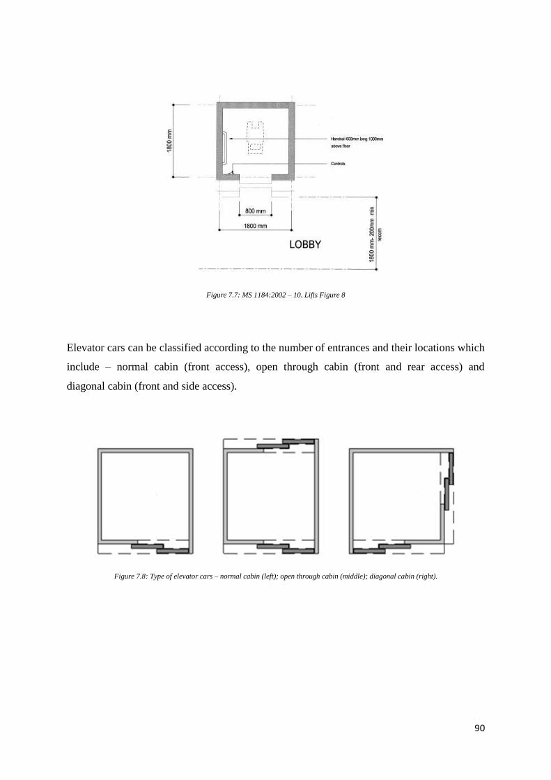
90
Figure 7.7: MS 1184:2002 – 10. Lifts Figure 8
Elevator cars can be classified according to the number of entrances and their locations which
include – normal cabin (front access), open through cabin (front and rear access) and
diagonal cabin (front and side access).
Figure 7.8: Type of elevator cars – normal cabin (left); open through cabin (middle); diagonal cabin (right).
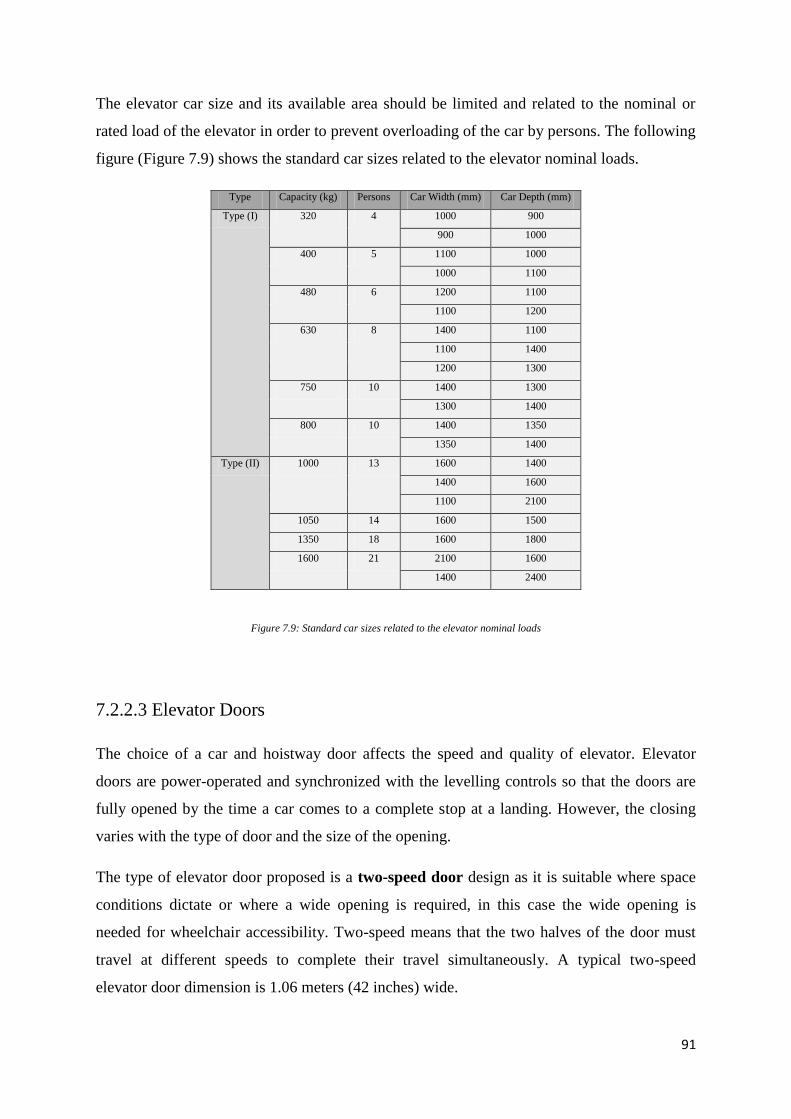
91
The elevator car size and its available area should be limited and related to the nominal or
rated load of the elevator in order to prevent overloading of the car by persons. The following
figure (Figure 7.9) shows the standard car sizes related to the elevator nominal loads.
Type Capacity (kg) Persons Car Width (mm) Car Depth (mm)
Type (I) 320 4 1000 900
900 1000
400 5 1100 1000
1000 1100
480 6 1200 1100
1100 1200
630 8 1400 1100
1100 1400
1200 1300
750 10 1400 1300
1300 1400
800 10 1400 1350
1350 1400
Type (II) 1000 13 1600 1400
1400 1600
1100 2100
1050 14 1600 1500
1350 18 1600 1800
1600 21 2100 1600
1400 2400
Figure 7.9: Standard car sizes related to the elevator nominal loads
7.2.2.3 Elevator Doors
The choice of a car and hoistway door affects the speed and quality of elevator. Elevator
doors are power-operated and synchronized with the levelling controls so that the doors are
fully opened by the time a car comes to a complete stop at a landing. However, the closing
varies with the type of door and the size of the opening.
The type of elevator door proposed is a two-speed door design as it is suitable where space
conditions dictate or where a wide opening is required, in this case the wide opening is
needed for wheelchair accessibility. Two-speed means that the two halves of the door must
travel at different speeds to complete their travel simultaneously. A typical two-speed
elevator door dimension is 1.06 meters (42 inches) wide.
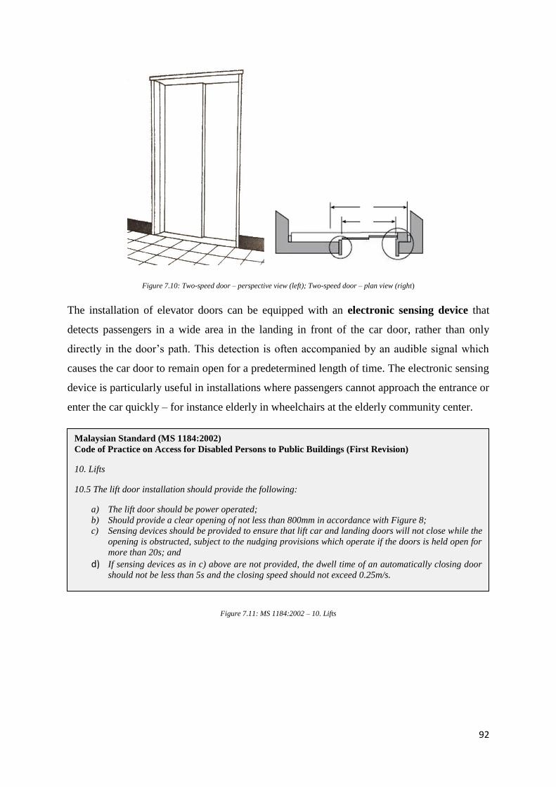
92
Figure 7.10: Two-speed door – perspective view (left); Two-speed door – plan view (right)
The installation of elevator doors can be equipped with an electronic sensing device that
detects passengers in a wide area in the landing in front of the car door, rather than only
directly in the door’s path. This detection is often accompanied by an audible signal which
causes the car door to remain open for a predetermined length of time. The electronic sensing
device is particularly useful in installations where passengers cannot approach the entrance or
enter the car quickly – for instance elderly in wheelchairs at the elderly community center.
Figure 7.11: MS 1184:2002 – 10. Lifts
Malaysian Standard (MS 1184:2002)
Code of Practice on Access for Disabled Persons to Public Buildings (First Revision)
10. Lifts
10.5 The lift door installation should provide the following:
a) The lift door should be power operated;
b) Should provide a clear opening of not less than 800mm in accordance with Figure 8;
c) Sensing devices should be provided to ensure that lift car and landing doors will not close while the
opening is obstructed, subject to the nudging provisions which operate if the doors is held open for
more than 20s; and
d) If sensing devices as in c) above are not provided, the dwell time of an automatically closing door
should not be less than 5s and the closing speed should not exceed 0.25m/s.
93
7.2.2.4 Signals and Operating Panels
The call buttons of an elevator should indicate the desired direction of travel and by visual
means confirm that a call has been placed. The hall lantern located at each car entrance must
visually indicate the direction of travel of an arriving elevator and preferably its present
location.
Figure 7.12: MS 1184:2002 – 10. Lifts
An audible signal should announce an elevator car’s arrival. This allows for waiting
passengers to move towards the arriving car (which in turn speeds the service when there are
multiple elevators).
Within the car, travel direction and present location of the car can be indicated either with
separate fixtures or by indicators built into the car panel.
Figure 7.13: MS 1184:2002 – 10. Lifts
Malaysian Standard (MS 1184:2002)
Code of Practice on Access for Disabled Persons to Public Buildings (First Revision)
10. Lifts
10.6 Lift controls should comply with the following:
a) Controls should be clearly indicated and easily operated in accordance with Clause 27.
b) Call buttons should either project from or be flush with the face of the car-operating panel. The
width or diameter of the button should not be less than 20mm.
c) Floor buttons, alarm buttons or emergency telephone and door control buttons in lift cars and
lobbies should not be higher than 1400mm above finished floor level. The hearing impaired can use
an alarm button and not the emergency telephone. An alarm button should always be provided, and
preferably of a design which lights up and produce sound when pressed to reassure those trapped
inside.
d) All buttons should be so designed that the sight impaired can identify them by touch. Button not
already so designed are best modified, by fixing, embossed or braille numbers or letter, not on the
buttons themselves, but adjacent to them.
Malaysian Standard (MS 1184:2002)
Code of Practice on Access for Disabled Persons to Public Buildings (First Revision)
10. Lifts
10.7 Lift indicators should be provided in accordance with following:
a) ‘Lift coming’ or ‘Call accepted’ indicators should be provided at each landing.
b) Indicators should be provided in each lift lobby to show the position and direction of the lift car;
alternatively, an audible indicator should be provided to indicate in advance the arrival of the lift
car and its direction of travel.
c) An indicator inside the car should signal clearly the direction of travel and the floor at which the lift
car is situated.
d) Embossed and braille numbering indicating each floor level should be provided beside the outside
call button.
94
7.2.2.5 Safety Devices
Roped hydraulic systems require a governor because the rope is holding the car up, as it still
has a risk when the rope broke.
Figure 7.14: Overspeed governor
A governor, or an overspeed governor, is an elevator device which acts as a stop device in
case the elevator runs beyond the rated speed. A cable, known as the governor rope, is
attached to the safeties on the underside of the car. When over-speeding is detected, the
governor grips the cable which applies the safeties that wedge against the guide rails and
stops the car.
95
1 Governor pulley 10 Safety contact
2 Cam curve 11 Locking plate
3 Base 12 Leaf spring
4 Adjusting bolt 13 Name plate
5 Tension spring 14 Lever
6 Roller 15 Rocker
7 Bolt 16 Pawl
8 Hat-type spring 17 Axel
9 Contact tappet 18 Rope fixing beam
Figure 7.15: Components of overspeed governor
Being a roped unit elevator, it is also equipped with a slack-rope safety in addition to the
other safeties used on direct-connected hydraulic systems.
7.2.3 Operation of System
In the operation of a roped hydraulic elevator system, the cantilevered car is lifted by cables
from the cable crosshead, which is in turn lifted (and lowered) by the single-section
telescoping piston (jack).
The rope is passed over a pulley in the piston crosshead – one end of the rope is attached to a
fixed point in the pit below the car, and the other end is attached to the base of the car. The
piston (plunger, jack) lifts the crosshead, which in turn lifts the car twice as far.
96
7.3 Proposal of Systems
The proposed mechanical transportation system for the elderly community center is the
Schumacher Roped Hydraulic Elevator (Figure 7.17).
Figure 7.16: Floor Plan of Elderly Community Centre
Figure 7.17: Schumacher Roped Hydraulic Elevator
Location of elevator
0
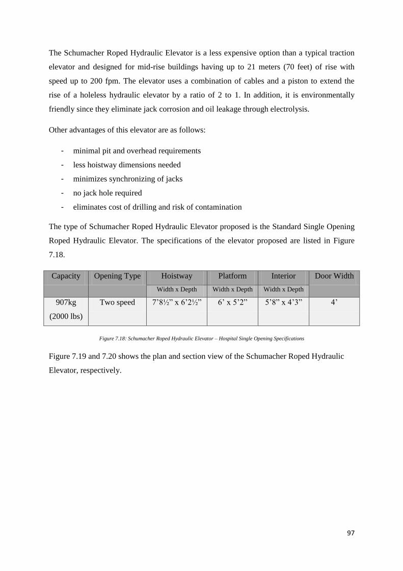
97
The Schumacher Roped Hydraulic Elevator is a less expensive option than a typical traction
elevator and designed for mid-rise buildings having up to 21 meters (70 feet) of rise with
speed up to 200 fpm. The elevator uses a combination of cables and a piston to extend the
rise of a holeless hydraulic elevator by a ratio of 2 to 1. In addition, it is environmentally
friendly since they eliminate jack corrosion and oil leakage through electrolysis.
Other advantages of this elevator are as follows:
- minimal pit and overhead requirements
- less hoistway dimensions needed
- minimizes synchronizing of jacks
- no jack hole required
- eliminates cost of drilling and risk of contamination
The type of Schumacher Roped Hydraulic Elevator proposed is the Standard Single Opening
Roped Hydraulic Elevator. The specifications of the elevator proposed are listed in Figure
7.18.
Capacity Opening Type Hoistway Platform Interior Door Width
Width x Depth Width x Depth Width x Depth
907kg
(2000 lbs)
Two speed 7’8½” x 6’2½” 6’ x 5’2” 5’8” x 4’3” 4’
Figure 7.18: Schumacher Roped Hydraulic Elevator – Hospital Single Opening Specifications
Figure 7.19 and 7.20 shows the plan and section view of the Schumacher Roped Hydraulic
Elevator, respectively.
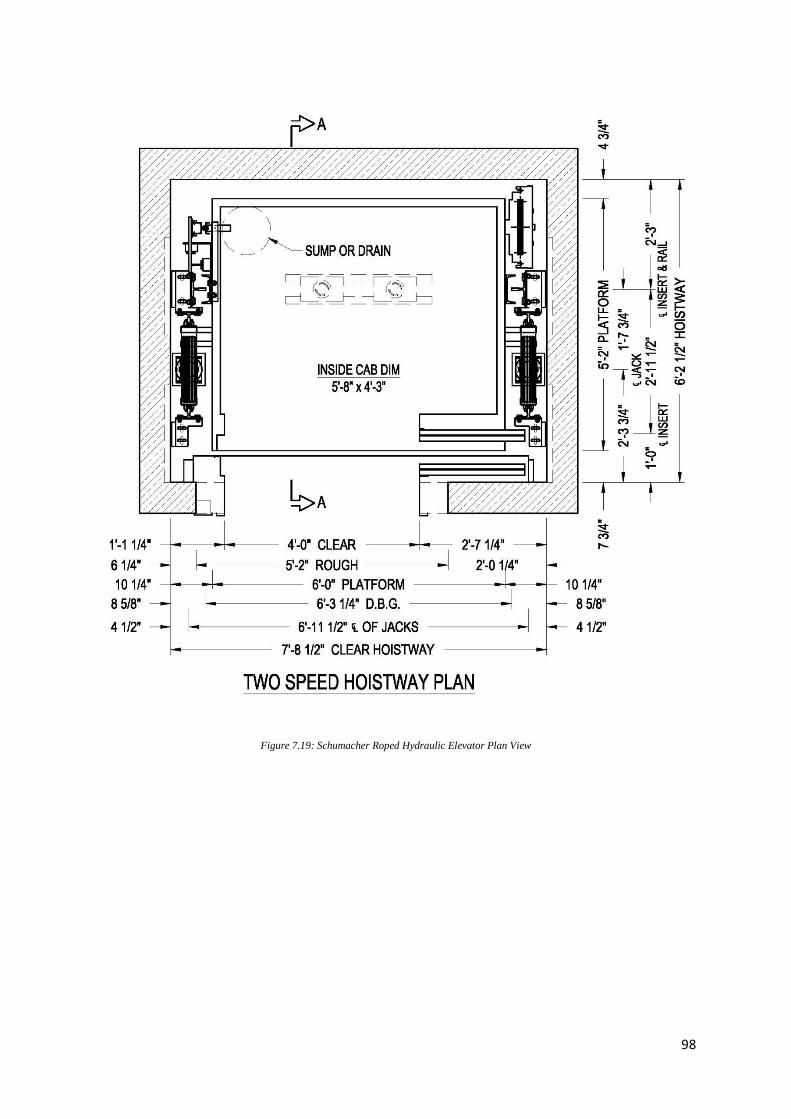
98
Figure 7.19: Schumacher Roped Hydraulic Elevator Plan View
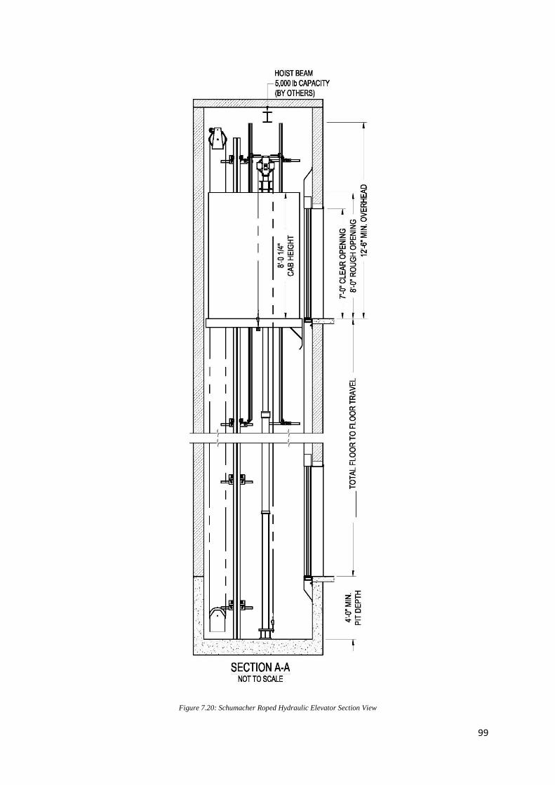
99
Figure 7.20: Schumacher Roped Hydraulic Elevator Section View
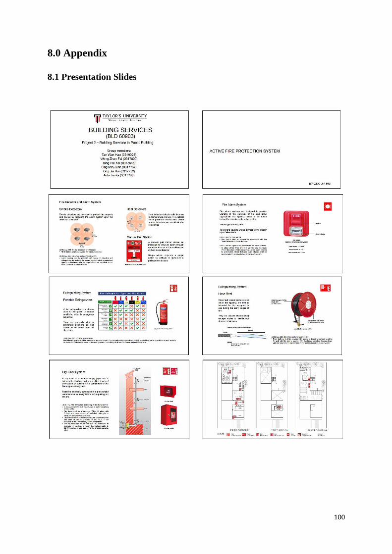
100
8.0 Appendix
8.1 Presentation Slides
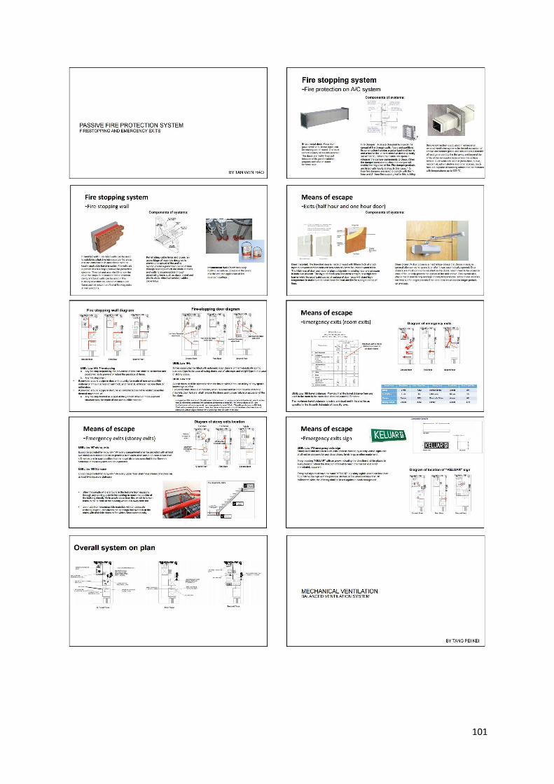
101
102
103
104
105
8.2 Passive Fire Protection System Floor Plan
106
8.3 Active Fire Protection System
8.3.1 Site Plan with Location of Fire Hydrant

107
8.3.2 Floor Plans with Complete Annotation
108
8.4 Mechanical Ventilation System
8.4.1 Section of Mechanical System

109
8.4.2 Floor Plan with Complete Annotation
110
8.5 Air Conditioning Ducting Plan
111
8.6 Mechanical Transport Plan
112
9.0 References
1. A Brief Introduction to Fire Extinguishers and Fire Types. (n.d.). Retrieved November
16, 2016, from http://www.pwfd.com/content/850_fs2.html
2. Arkam M. (2009). Mechanical Ventilation. Retrieved November 17, 2016, from
http://www.slideshare.net/arkam_slideshare/mechanical-ventilation
3. Back to Basics with the Fire Triangle - Elite Fire Protection. (n.d.). Retrieved November
15, 2016, from http://www.elitefire.co.uk/basics-fire-triangle/
4. Bode Components. (n.d.). Retrieved November 17, 2016, from http://www.bode-
components.com/en/produkte/geschwindigkeitsbegrenzer/
5. Dry Riser - Cabinets - Inlet Cabinets - Outlet Cabinets - Delta Fire. (n.d.). Retrieved
November 16, 2016, from http://www.deltafire.co.uk/products/dry-riser/dry-riser-
cabinets/
6. Elevator Safety System. (n.d.). Retrieved November 17, 2016, from http://www.electrical-
knowhow.com/2012/04/elevator-safety-system.html
7. Fire Extinguishers, Hose Reels and Fire Blankets. (n.d.). Retrieved November 16, 2016,
from http://www.fireprotection.org.nz/information-on/extinguishes-and-hose-reels
8. Grondzik, W.T. & Kwok, A.G. (2014). Mechanical and electrical equipment for
buildings. 12th
Edition. New York: John Wiley.
9. HRV or ERV? (n.d.). Retrieved November 17, 2016, from
http://www.greenbuildingadvisor.com/blogs/dept/musings/hrv-or-erv
10. Information about Fire Hose Reels. (n.d.). Retrieved November 16, 2016, from
http://www.firehosereels.com.au/firehosereels.htm
11. Info-610: Central Fan Integrated Ventilation Systems. (n.d.). Retrieved November 17,
2016, from https://buildingscience.com/documents/information-sheets/information-sheet-
ventilation-system
113
12. Lopol. (n.d.). Retrieved November 16, 2016, from http://www.lopol.org/article/fire-
alarm-system-introduction-and-importance-of-fire-alarm-system
13. Package Type Hygienic Air Handling Units. (2015). Retrieved November 17, 2016, from
https://www.acsklima.com/en/products/package-type-hygienic-air-handling-units/
14. Passive and Active Protection - Cornwall Council. (2013). Retrieved November 16, 2016,
from http://www.cornwall.gov.uk/community-and-living/cornwall-fire-and-rescue-
service-homepage/business-fire-safety/protecting-your-building/passive-and-active-
protection/
15. Roped Hydraulic Elevators. (n.d.). Retrieved November 17, 2016, from
http://www.schumacherelevator.com/elevators/hydraulic-elevators/roped-hydraulic-
elevators.aspx
16. The best way to create and organize your Revit Elevators in your Project. (n.d.).
Retrieved November 17, 2016, from http://revit-content.com/content/elevator/index.htm
17. The consequences of fire. (n.d.). Retrieved November 15, 2016, from
http://www.nfpa.org/news-and-research/news-and-media/press-room/reporters-guide-to-
fire-and-nfpa/consequences-of-fire