building service-oriented banking solutions with ibm ... · pdf filebuilding service-oriented...
TRANSCRIPT
ibm.com/redbooks Redpaper
Building Service-Oriented Banking Solutions with IBM Banking Industry Models and Rational SDP
Nick NorrisBrian YarowBrian Byrne
Service-oriented business solution development and delivery acceleration
Business-driven and model-driven solution development and delivery
Step-by-step tooling guidance
Front cover

Building Service-Oriented Banking Solutions with IBM Banking Industry Models and Rational SDP
October 2007
International Technical Support Organization

© Copyright International Business Machines Corporation 2007. All rights reserved.Note to U.S. Government Users Restricted Rights -- Use, duplication or disclosure restricted by GSA ADPSchedule Contract with IBM Corp.
First Edition (October 2007)
This edition applies to Version 6 of IBM Rational Software Modeler, IBM Rational Software Architect, IBM Rational Application Developer, IBM Rational RequisitePro, IBM WebSphere Business Modeler, and IBM WebSphere Integration Developer.
Note: Before using this information and the product it supports, read the information in “Notices” on page ix.
Contents
Notices . . . . . . . . . . . . . . . . . . . . . . . . . . . . . . . . . . . . . . . . . . . . . . . . . . . . . . . ixTrademarks . . . . . . . . . . . . . . . . . . . . . . . . . . . . . . . . . . . . . . . . . . . . . . . . . . . . x
Preface . . . . . . . . . . . . . . . . . . . . . . . . . . . . . . . . . . . . . . . . . . . . . . . . . . . . . . . xiWhat is in the Redpaper . . . . . . . . . . . . . . . . . . . . . . . . . . . . . . . . . . . . . . . xiiWhat is not in this Redpaper . . . . . . . . . . . . . . . . . . . . . . . . . . . . . . . . . . . . xiiTarget audience . . . . . . . . . . . . . . . . . . . . . . . . . . . . . . . . . . . . . . . . . . . . . xiii
The team that wrote this Redpaper . . . . . . . . . . . . . . . . . . . . . . . . . . . . . . . . . xivBecome a published author . . . . . . . . . . . . . . . . . . . . . . . . . . . . . . . . . . . . . . . xvComments welcome. . . . . . . . . . . . . . . . . . . . . . . . . . . . . . . . . . . . . . . . . . . . . xv
Chapter 1. Introduction . . . . . . . . . . . . . . . . . . . . . . . . . . . . . . . . . . . . . . . . . . 11.1 Purpose . . . . . . . . . . . . . . . . . . . . . . . . . . . . . . . . . . . . . . . . . . . . . . . . . . . . 21.2 Why use enterprise models. . . . . . . . . . . . . . . . . . . . . . . . . . . . . . . . . . . . . 2
1.2.1 IBM Banking Industry Enterprise Models (IFW) and SDP. . . . . . . . . . 3
Chapter 2. IBM Banking Industry Enterprise Models (IFW) overview . . . . 52.1 The industry models . . . . . . . . . . . . . . . . . . . . . . . . . . . . . . . . . . . . . . . . . . 62.2 Customizing the models . . . . . . . . . . . . . . . . . . . . . . . . . . . . . . . . . . . . . . . 72.3 Top-down versus bottom-up . . . . . . . . . . . . . . . . . . . . . . . . . . . . . . . . . . . . 9
Chapter 3. Introduction to the IBM Rational Software Delivery Platform. 113.1 IBM Rational Software Delivery Platform . . . . . . . . . . . . . . . . . . . . . . . . . 12
Chapter 4. Introduction to creating service-oriented business solutions for the financial services sector . . . . . . . . . . . . . . . . . . . . . . . . . . . 15
4.1 Overview of creating service-oriented business solutions for the financial services sector . . . . . . . . . . . . . . . . . . . . . . . . . . . . . . . . . . . . . . . . . . . . . 16
4.1.1 Define project scope . . . . . . . . . . . . . . . . . . . . . . . . . . . . . . . . . . . . . 184.1.2 Analyze processes . . . . . . . . . . . . . . . . . . . . . . . . . . . . . . . . . . . . . . 194.1.3 Analyze services . . . . . . . . . . . . . . . . . . . . . . . . . . . . . . . . . . . . . . . . 194.1.4 Design services. . . . . . . . . . . . . . . . . . . . . . . . . . . . . . . . . . . . . . . . . 194.1.5 Design processes . . . . . . . . . . . . . . . . . . . . . . . . . . . . . . . . . . . . . . . 204.1.6 Implement services and processes. . . . . . . . . . . . . . . . . . . . . . . . . . 20
Chapter 5. Define Project Scope . . . . . . . . . . . . . . . . . . . . . . . . . . . . . . . . . 215.1 Introduction to define Project Scope . . . . . . . . . . . . . . . . . . . . . . . . . . . . . 225.2 Using IBM Rational SDP to define Project Scope . . . . . . . . . . . . . . . . . . . 225.3 Capture business goals. . . . . . . . . . . . . . . . . . . . . . . . . . . . . . . . . . . . . . . 23
© Copyright IBM Corp. 2007. All rights reserved. iii
5.4 Determine business functional scope . . . . . . . . . . . . . . . . . . . . . . . . . . . . 245.4.1 Establish relationship between business goals and business functional
areas. . . . . . . . . . . . . . . . . . . . . . . . . . . . . . . . . . . . . . . . . . . . . . . . . 265.4.2 Specify which business goals and business functional areas are
candidates to be in-scope for a new project . . . . . . . . . . . . . . . . . . . 295.5 Identify and prioritize in-scope business processes . . . . . . . . . . . . . . . . . 31
5.5.1 Review the set of candidate in-scope business processes. . . . . . . . 315.5.2 Analyze and prioritize the candidate set of in-scope business processes
for the new project . . . . . . . . . . . . . . . . . . . . . . . . . . . . . . . . . . . . . . 325.5.3 Specify the in-scope business processes of the project . . . . . . . . . . 35
5.6 Transitioning to Analyze Processes . . . . . . . . . . . . . . . . . . . . . . . . . . . . . 36
Chapter 6. Analyze Processes . . . . . . . . . . . . . . . . . . . . . . . . . . . . . . . . . . . 376.1 Introduction to Analyze Processes . . . . . . . . . . . . . . . . . . . . . . . . . . . . . . 386.2 Using IBM Rational SDP to Analyze Processes . . . . . . . . . . . . . . . . . . . . 396.3 Refine and decompose business processes. . . . . . . . . . . . . . . . . . . . . . . 39
6.3.1 Example 1: automate an existing business task . . . . . . . . . . . . . . . . 406.3.2 Example 2: add a new task to an existing business process . . . . . . 44
6.4 Refine textual business requirements . . . . . . . . . . . . . . . . . . . . . . . . . . . . 546.5 Capture business opportunities. . . . . . . . . . . . . . . . . . . . . . . . . . . . . . . . . 556.6 Export models to RSA/M . . . . . . . . . . . . . . . . . . . . . . . . . . . . . . . . . . . . . . 596.7 Transitioning to Analyze Services . . . . . . . . . . . . . . . . . . . . . . . . . . . . . . . 59
Chapter 7. Analyze Services . . . . . . . . . . . . . . . . . . . . . . . . . . . . . . . . . . . . 617.1 Introduction to Analyze Services . . . . . . . . . . . . . . . . . . . . . . . . . . . . . . . . 627.2 Using IBM Rational SDP to Analyze Services. . . . . . . . . . . . . . . . . . . . . . 627.3 Analyze business processes for service candidates . . . . . . . . . . . . . . . . . 64
7.3.1 Confirm existence of existing service candidate: example 1. . . . . . . 647.3.2 Adding a new business activity: example 2. . . . . . . . . . . . . . . . . . . . 677.3.3 Create a service candidate use case in RequisitePro. . . . . . . . . . . . 72
7.4 Create and define the business motivation and scope for an IT project . . 777.4.1 Analyze and prioritize business opportunities . . . . . . . . . . . . . . . . . . 787.4.2 Create an IT project to fulfill business opportunities . . . . . . . . . . . . . 79
7.5 Define an IT project’s IT scope . . . . . . . . . . . . . . . . . . . . . . . . . . . . . . . . . 807.5.1 Determine business activities associated with the IT project's business
scope . . . . . . . . . . . . . . . . . . . . . . . . . . . . . . . . . . . . . . . . . . . . . . . . 817.5.2 Identify and assign IFW-based service candidate use cases to an IT
project's IT scope . . . . . . . . . . . . . . . . . . . . . . . . . . . . . . . . . . . . . . . 827.6 Detail the service candidate use case. . . . . . . . . . . . . . . . . . . . . . . . . . . . 85
7.6.1 Detail the service candidate use case specification . . . . . . . . . . . . . 857.6.2 Analyze service candidate informational requirements. . . . . . . . . . . 877.6.3 Customized BOM types . . . . . . . . . . . . . . . . . . . . . . . . . . . . . . . . . . 917.6.4 Define boundary of type (BOT) . . . . . . . . . . . . . . . . . . . . . . . . . . . . . 93
iv Building Service-Oriented Banking Solutions with IBM Banking Industry Models and Rational SDP
7.6.5 Define internal use case view . . . . . . . . . . . . . . . . . . . . . . . . . . . . . . 947.7 Transitioning to Design Services. . . . . . . . . . . . . . . . . . . . . . . . . . . . . . . . 96
Chapter 8. Design Services . . . . . . . . . . . . . . . . . . . . . . . . . . . . . . . . . . . . . 978.1 Introduction to Design Services. . . . . . . . . . . . . . . . . . . . . . . . . . . . . . . . . 988.2 Using IBM Rational SDP to Design Services . . . . . . . . . . . . . . . . . . . . . . 998.3 Example 1: update Analyze Customer Relationship service in IDM . . . . . 99
8.3.1 Locate service use case in BOM. . . . . . . . . . . . . . . . . . . . . . . . . . . . 998.3.2 Locate the service use case component interface in the IDM. . . . . 1018.3.3 Determine whether the service information requirements are realized by
its corresponding IDM interface operation parameters . . . . . . . . . . 1028.3.4 Update the service interface design in IDM to match its BOM
specification . . . . . . . . . . . . . . . . . . . . . . . . . . . . . . . . . . . . . . . . . . 1048.4 Example 2: add Apply Anti Money Laundering Policy service to IDM. . . 108
8.4.1 Determine where service use case realization is located in IDM . . 1098.4.2 Add new IDM interface . . . . . . . . . . . . . . . . . . . . . . . . . . . . . . . . . . 1108.4.3 Assign new interface to component . . . . . . . . . . . . . . . . . . . . . . . . 1128.4.4 Create IDM realization of the new BOM service use case . . . . . . . 1148.4.5 Map BOM service use case to IDM interface realization . . . . . . . . 115
8.5 Construct IDM collaborations from BOM internal use case views. . . . . . 1178.5.1 Create a new collaboration . . . . . . . . . . . . . . . . . . . . . . . . . . . . . . . 1188.5.2 Create the service collaboration in the communication diagram. . . 120
8.6 Extend IDM class model based on BOM changes . . . . . . . . . . . . . . . . . 1288.7 Establish BOM-IDM mappings for new BOM classes . . . . . . . . . . . . . . . 131
8.7.1 Determine whether a BOM class already has a mapping to an IDM class and interface . . . . . . . . . . . . . . . . . . . . . . . . . . . . . . . . . . . . . . . . . . 131
8.7.2 If the new BOM class should be mapped to an existing IDM class and type interface . . . . . . . . . . . . . . . . . . . . . . . . . . . . . . . . . . . . . . . . . 132
8.7.3 If the new BOM class should be mapped to a new IDM class and type interface . . . . . . . . . . . . . . . . . . . . . . . . . . . . . . . . . . . . . . . . . . . . . 132
8.7.4 Create the mapping from the new BOM class to its IDM class and type interface realization. . . . . . . . . . . . . . . . . . . . . . . . . . . . . . . . . . . . . 133
8.8 Creating service parameters for complex data aggregates—working with BOT diagrams . . . . . . . . . . . . . . . . . . . . . . . . . . . . . . . . . . . . . . . . . . . . 133
8.9 Updating component dependencies . . . . . . . . . . . . . . . . . . . . . . . . . . . . 1368.9.1 Adding a new component . . . . . . . . . . . . . . . . . . . . . . . . . . . . . . . . 1378.9.2 Add a new dependency. . . . . . . . . . . . . . . . . . . . . . . . . . . . . . . . . . 138
8.10 Validating the model and generating output . . . . . . . . . . . . . . . . . . . . . 1408.10.1 Overview of IM&A generators . . . . . . . . . . . . . . . . . . . . . . . . . . . . 1418.10.2 Overview of the IM&A Java Design Model (JDM) . . . . . . . . . . . . . 1428.10.3 Run the IMA WSDL with XSD generators . . . . . . . . . . . . . . . . . . 1438.10.4 Creating the Java Design Model . . . . . . . . . . . . . . . . . . . . . . . . . . 1468.10.5 Generating Java code from the JDM . . . . . . . . . . . . . . . . . . . . . . 149
Contents v
Chapter 9. Design Processes . . . . . . . . . . . . . . . . . . . . . . . . . . . . . . . . . . . 1519.1 Introduction to Design Processes . . . . . . . . . . . . . . . . . . . . . . . . . . . . . . 1529.2 Using IBM Rational SDP to Design Processes . . . . . . . . . . . . . . . . . . . . 1529.3 Construct process design project . . . . . . . . . . . . . . . . . . . . . . . . . . . . . . 1539.4 Refine process-service boundary . . . . . . . . . . . . . . . . . . . . . . . . . . . . . . 1589.5 Design data containers . . . . . . . . . . . . . . . . . . . . . . . . . . . . . . . . . . . . . . 1619.6 Define flow control logic . . . . . . . . . . . . . . . . . . . . . . . . . . . . . . . . . . . . . 168
9.6.1 Updating decision output branches. . . . . . . . . . . . . . . . . . . . . . . . . 1689.6.2 Updating loopback paths to nested loop structures . . . . . . . . . . . . 174
9.7 Design resource assignments . . . . . . . . . . . . . . . . . . . . . . . . . . . . . . . . . 1769.8 Simulate Design Process execution (optional) . . . . . . . . . . . . . . . . . . . . 1799.9 Generate BPEL . . . . . . . . . . . . . . . . . . . . . . . . . . . . . . . . . . . . . . . . . . . . 1809.10 Transitioning to Implement Services and Processes . . . . . . . . . . . . . . 182
Chapter 10. Implement Services and Processes . . . . . . . . . . . . . . . . . . . 183
Appendix A. Workstation configuration and software installation. . . . . 185A.1 Workstation configuration . . . . . . . . . . . . . . . . . . . . . . . . . . . . . . . . . . . . 186A.2 Installation procedure . . . . . . . . . . . . . . . . . . . . . . . . . . . . . . . . . . . . . . . 186
A.2.1 Install Rational Software Architect . . . . . . . . . . . . . . . . . . . . . . . . . 187A.2.2 Install WebSphere Integration Developer . . . . . . . . . . . . . . . . . . . . 188A.2.3 Install WebSphere Business Modeler - Advanced edition . . . . . . . 189A.2.4 Install Rational RequisitePro. . . . . . . . . . . . . . . . . . . . . . . . . . . . . . 190A.2.5 Install industry models RSA support. . . . . . . . . . . . . . . . . . . . . . . . 190
Appendix B. Modeling project setup and management. . . . . . . . . . . . . . 191B.1 RequisitePro project setup . . . . . . . . . . . . . . . . . . . . . . . . . . . . . . . . . . . 192
B.1.1 Create a RequisitePro project. . . . . . . . . . . . . . . . . . . . . . . . . . . . . 192B.2 Rational Software Architect/Modeler setup. . . . . . . . . . . . . . . . . . . . . . . 195
B.2.1 Create a new RSA Workspace and IFW modeling projects . . . . . . 195B.2.2 Create IFW modeling projects . . . . . . . . . . . . . . . . . . . . . . . . . . . . 195
B.3 Link the Rational Software Architect and RequisitePro projects. . . . . . . 198B.3.1 Open the RequisitePro project from Rational Software Architect . . 198B.3.2 Examine and set the RequisitePro project integration properties. . 200B.3.3 Navigate or create RSA/M element/RequisitePro requirement linkages
203B.4 IFW Process Model Management: from RSA to WBM and back again . 207
B.4.1 Export the IFW Process Model from RSA/M . . . . . . . . . . . . . . . . . 207B.4.2 Import IFW process models into WebSphere Business Modeler . . 209B.4.3 Export models from WebSphere Business Modeler . . . . . . . . . . . . 212B.4.4 Import the Process Model into RSA . . . . . . . . . . . . . . . . . . . . . . . . 214
B.5 Model management setup and preferences . . . . . . . . . . . . . . . . . . . . . . 215
Appendix C. IMA generator options . . . . . . . . . . . . . . . . . . . . . . . . . . . . . 219
vi Building Service-Oriented Banking Solutions with IBM Banking Industry Models and Rational SDP
C.1 Generator options . . . . . . . . . . . . . . . . . . . . . . . . . . . . . . . . . . . . . . . . . . 220C.2 XML namespace. . . . . . . . . . . . . . . . . . . . . . . . . . . . . . . . . . . . . . . . . . . 220C.3 Enable echo back of request parameters in response messages . . . . . 221C.4 Splitting options . . . . . . . . . . . . . . . . . . . . . . . . . . . . . . . . . . . . . . . . . . . 221
C.4.1 Split output into multiple schemas . . . . . . . . . . . . . . . . . . . . . . . . . 222C.4.2 Split output into multiple namespaces . . . . . . . . . . . . . . . . . . . . . . 222
C.5 Binding options . . . . . . . . . . . . . . . . . . . . . . . . . . . . . . . . . . . . . . . . . . . . 223C.5.1 Use RPC style . . . . . . . . . . . . . . . . . . . . . . . . . . . . . . . . . . . . . . . . 223C.5.2 Use Document/Literal style. . . . . . . . . . . . . . . . . . . . . . . . . . . . . . . 223C.5.3 No Bindings . . . . . . . . . . . . . . . . . . . . . . . . . . . . . . . . . . . . . . . . . . 223
C.6 Association options. . . . . . . . . . . . . . . . . . . . . . . . . . . . . . . . . . . . . . . . . 223C.6.1 Nest associations . . . . . . . . . . . . . . . . . . . . . . . . . . . . . . . . . . . . . . 224C.6.2 Nest aggregations by value . . . . . . . . . . . . . . . . . . . . . . . . . . . . . . 224C.6.3 Nest all aggregations . . . . . . . . . . . . . . . . . . . . . . . . . . . . . . . . . . . 224C.6.4 Nest all associations. . . . . . . . . . . . . . . . . . . . . . . . . . . . . . . . . . . . 224C.6.5 Include generic references . . . . . . . . . . . . . . . . . . . . . . . . . . . . . . . 224C.6.6 Make all associations optional . . . . . . . . . . . . . . . . . . . . . . . . . . . . 225
Abbreviations and acronyms . . . . . . . . . . . . . . . . . . . . . . . . . . . . . . . . . . . 227
Related publications . . . . . . . . . . . . . . . . . . . . . . . . . . . . . . . . . . . . . . . . . . 229IBM Redbooks . . . . . . . . . . . . . . . . . . . . . . . . . . . . . . . . . . . . . . . . . . . . . . . . 229Other publications . . . . . . . . . . . . . . . . . . . . . . . . . . . . . . . . . . . . . . . . . . . . . 230Online resources . . . . . . . . . . . . . . . . . . . . . . . . . . . . . . . . . . . . . . . . . . . . . . 232How to get IBM Redbooks . . . . . . . . . . . . . . . . . . . . . . . . . . . . . . . . . . . . . . . 232Help from IBM . . . . . . . . . . . . . . . . . . . . . . . . . . . . . . . . . . . . . . . . . . . . . . . . 232
Index . . . . . . . . . . . . . . . . . . . . . . . . . . . . . . . . . . . . . . . . . . . . . . . . . . . . . . . 233
Contents vii

viii Building Service-Oriented Banking Solutions with IBM Banking Industry Models and Rational SDP

Notices
This information was developed for products and services offered in the U.S.A.
IBM may not offer the products, services, or features discussed in this document in other countries. Consult your local IBM representative for information on the products and services currently available in your area. Any reference to an IBM product, program, or service is not intended to state or imply that only that IBM product, program, or service may be used. Any functionally equivalent product, program, or service that does not infringe any IBM intellectual property right may be used instead. However, it is the user's responsibility to evaluate and verify the operation of any non-IBM product, program, or service.
IBM may have patents or pending patent applications covering subject matter described in this document. The furnishing of this document does not give you any license to these patents. You can send license inquiries, in writing, to: IBM Director of Licensing, IBM Corporation, North Castle Drive, Armonk, NY 10504-1785 U.S.A.
The following paragraph does not apply to the United Kingdom or any other country where such provisions are inconsistent with local law: INTERNATIONAL BUSINESS MACHINES CORPORATION PROVIDES THIS PUBLICATION "AS IS" WITHOUT WARRANTY OF ANY KIND, EITHER EXPRESS OR IMPLIED, INCLUDING, BUT NOT LIMITED TO, THE IMPLIED WARRANTIES OF NON-INFRINGEMENT, MERCHANTABILITY OR FITNESS FOR A PARTICULAR PURPOSE. Some states do not allow disclaimer of express or implied warranties in certain transactions, therefore, this statement may not apply to you.
This information could include technical inaccuracies or typographical errors. Changes are periodically made to the information herein; these changes will be incorporated in new editions of the publication. IBM may make improvements and changes in the product(s) or the program(s) described in this publication at any time without notice.
Any references in this information to non-IBM Web sites are provided for convenience only and do not in any manner serve as an endorsement of those Web sites. The materials at those Web sites are not part of the materials for this IBM product and use of those Web sites is at your own risk.
IBM may use or distribute any of the information you supply in any way it believes appropriate without incurring any obligation to you.
Information concerning non-IBM products was obtained from the suppliers of those products, their published announcements or other publicly available sources. IBM has not tested those products and cannot confirm the accuracy of performance, compatibility or any other claims related to non-IBM products. Questions on the capabilities of non-IBM products should be addressed to the suppliers of those products.
This information contains examples of data and reports used in daily business operations. To illustrate them as completely as possible, the examples include the names of individuals, companies, brands, and products. All of these names are fictitious and any similarity to the names and addresses used by an actual business enterprise is entirely coincidental.
COPYRIGHT LICENSE:
This information contains sample application programs in source language, which illustrate programming techniques on various operating platforms. You may copy, modify, and distribute these sample programs in any form without payment to IBM, for the purposes of developing, using, marketing or distributing application programs conforming to the application programming interface for the operating platform for which the sample programs are written. These examples have not been thoroughly tested under all conditions. IBM, therefore, cannot guarantee or imply reliability, serviceability, or function of these programs.
© Copyright IBM Corp. 2007. All rights reserved. ix
TrademarksThe following terms are trademarks of the International Business Machines Corporation in the United States, other countries, or both:
Redbooks (logo) ®developerWorks®ClearCase®ClearQuest®Component Business Model™CICS®
IBM®Rational Rose®Rational Unified Process®Rational®Redbooks®Requisite®
RequisitePro®RUP®WebSphere®XDE™
The following terms are trademarks of other companies:
Enterprise JavaBeans, EJB, Java, JavaBeans, JavaServer, JavaServer Pages, JSP, J2EE, RSM, and all Java-based trademarks are trademarks of Sun Microsystems, Inc. in the United States, other countries, or both.
Expression, Microsoft, Windows, and the Windows logo are trademarks of Microsoft Corporation in the United States, other countries, or both.
Pentium, Intel logo, Intel Inside logo, and Intel Centrino logo are trademarks or registered trademarks of Intel Corporation or its subsidiaries in the United States, other countries, or both.
Other company, product, or service names may be trademarks or service marks of others.
x Building Service-Oriented Banking Solutions with IBM Banking Industry Models and Rational SDP

Preface
Among the critical business success factors for enterprises to realize the value of service-oriented business transformation is the ability to effectively and efficiently analyze the business needs and use that analysis to drive the transformation of the business and its supporting architecture. A common language, blueprints (models), a governable enterprise service-oriented solution development and delivery platform, and processes are key components and enablers needed to implement these critical business success factors.
This IBM® Redpaper covers important aspects on how to implement each of these key components and enablers, and how to use them together to achieve the needed business and technical results. Specifically, this Redpaper provides important positioning information and detailed tooling guidance on how to use the IBM Rational® Software Delivery Platform (SDP) with the IBM Banking Industry Enterprise Models (IFW) to develop and deliver service-oriented banking solutions. The approach described in this paper can be extended to other IBM Industry Models including the IBM insurance models, the Insurance Application Architecture (IAA). This approach also does not exclude other possible approaches to using the IBM Industry Models (including the IBM Insurance Models) or combining this approach with others.
© Copyright IBM Corp. 2007. All rights reserved. xi
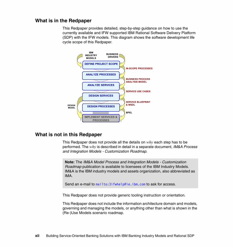
What is in the RedpaperThis Redpaper provides detailed, step-by-step guidance on how to use the currently available and IFW supported IBM Rational Software Delivery Platform (SDP) with the IFW models. This diagram shows the software development life cycle scope of this Redpaper.
What is not in this RedpaperThis Redpaper does not provide all the details on why each step has to be performed. The why is described in detail in a separate document, IM&A Process and Integration Models - Customization Roadmap.
This Redpaper does not provide generic tooling instruction or orientation.
This Redpaper does not include the information architecture domain and models, governing and managing the models, or anything other than what is shown in the (Re-)Use Models scenario roadmap.
DEFINE PROJECT SCOPE
ANALYZE SERVICES
DESIGN SERVICES
DESIGN PROCESSES
IMPLEMENT SERVICES & PROCESSES
ANALYZE PROCESSES
IN-SCOPE PROCESSES
BUSINESS PROCESS ANALYSIS MODEL
SERVICE BLUEPRINT& WSDL
BPEL
SERVICE USE CASES
DESIGNMODEL
IBMINDUSTRYMODELS
BUSINESSDRIVERS
Note: The IM&A Model Process and Integration Models - Customization Roadmap publication is available to licensees of the IBM Industry Models. IM&A is the IBM industry models and assets organization, also abbreviated as IMA.
Send an e-mail to mailto:[email protected] to ask for access.
xii Building Service-Oriented Banking Solutions with IBM Banking Industry Models and Rational SDP
Target audienceThis Redpaper provides essential guidance for project planners, analysts, and designers working with the IBM IFW models and SDP, especially in the context of evolving a service-oriented architecture. This includes:
� Strategists and planners—Those involved in the initial inception and evaluation of projects, and those concerned with potential overlap and producer/consumer relationships between projects. This Redpaper provides detailed guidance on how to use of the IFW models with the SDP to define business and IT project scope.
� Business analysts—This Redpaper provides detailed guidance on how to use the IFW models and SDP to define business models at a sufficiently detailed level to clearly capture business requirements to fulfill a given set of business objectives.
� Service analysts—Those involved in the detailed analysis of services and subsystems at a logical level will be intimately involved in the definition of service candidate use cases and the supporting information types within the Business Object Model (BOM), completing the definition of business requirements and providing the analysis specification for the subsequent service design and other activities.
� Solution architects—Those responsible for the overall solutions architecture of a project will be consuming the requirements as expressed within the Process models and BOM, and producing a solution architecture that has a service-based pattern derived from the constructs of the Interface Design Model (IDM).
Preface xiii
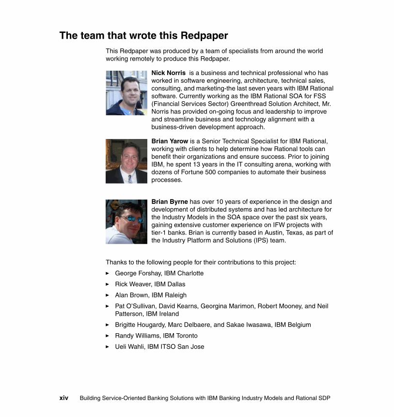
The team that wrote this RedpaperThis Redpaper was produced by a team of specialists from around the world working remotely to produce this Redpaper.
Nick Norris is a business and technical professional who has worked in software engineering, architecture, technical sales, consulting, and marketing-the last seven years with IBM Rational software. Currently working as the IBM Rational SOA for FSS (Financial Services Sector) Greenthread Solution Architect, Mr. Norris has provided on-going focus and leadership to improve and streamline business and technology alignment with a business-driven development approach.
Brian Yarow is a Senior Technical Specialist for IBM Rational, working with clients to help determine how Rational tools can benefit their organizations and ensure success. Prior to joining IBM, he spent 13 years in the IT consulting arena, working with dozens of Fortune 500 companies to automate their business processes.
Brian Byrne has over 10 years of experience in the design and development of distributed systems and has led architecture for the Industry Models in the SOA space over the past six years, gaining extensive customer experience on IFW projects with tier-1 banks. Brian is currently based in Austin, Texas, as part of the Industry Platform and Solutions (IPS) team.
Thanks to the following people for their contributions to this project:
� George Forshay, IBM Charlotte
� Rick Weaver, IBM Dallas
� Alan Brown, IBM Raleigh
� Pat O’Sullivan, David Kearns, Georgina Marimon, Robert Mooney, and Neil Patterson, IBM Ireland
� Brigitte Hougardy, Marc Delbaere, and Sakae Iwasawa, IBM Belgium
� Randy Williams, IBM Toronto
� Ueli Wahli, IBM ITSO San Jose
xiv Building Service-Oriented Banking Solutions with IBM Banking Industry Models and Rational SDP

Become a published authorJoin us for a two- to six-week residency program! Help write an IBM Redbook dealing with specific products or solutions, while getting hands-on experience with leading-edge technologies. You'll have the opportunity to team with IBM technical professionals, Business Partners, and Clients.
Your efforts will help increase product acceptance and customer satisfaction. As a bonus, you will develop a network of contacts in IBM development labs, and increase your productivity and marketability.
Find out more about the residency program, browse the residency index, and apply online at:
ibm.com/redbooks/residencies.html
Comments welcomeYour comments are important to us!
We want our papers to be as helpful as possible. Send us your comments about this Redpaper or other Redbooks® in one of the following ways:
� Use the online Contact us review IBM Redbooks publication form found at:
ibm.com/redbooks
� Send your comments in an e-mail to:
� Mail your comments to:
IBM Corporation, International Technical Support OrganizationDept. HYTD Mail Station P0992455 South RoadPoughkeepsie, NY 12601-5400
Preface xv

xvi Building Service-Oriented Banking Solutions with IBM Banking Industry Models and Rational SDP

Chapter 1. Introduction
This chapter provides a high-level introduction to the purpose and motivation of this Redpaper, including its scope.
1
© Copyright IBM Corp. 2007. All rights reserved. 1
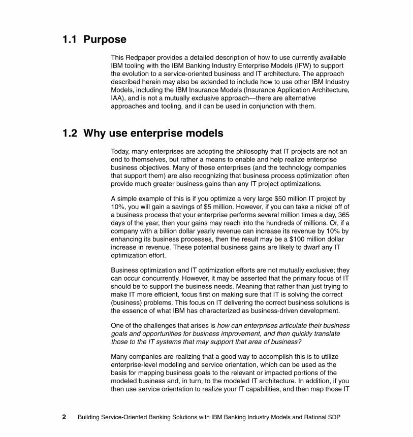
1.1 Purpose
This Redpaper provides a detailed description of how to use currently available IBM tooling with the IBM Banking Industry Enterprise Models (IFW) to support the evolution to a service-oriented business and IT architecture. The approach described herein may also be extended to include how to use other IBM Industry Models, including the IBM Insurance Models (Insurance Application Architecture, IAA), and is not a mutually exclusive approach—there are alternative approaches and tooling, and it can be used in conjunction with them.
1.2 Why use enterprise models
Today, many enterprises are adopting the philosophy that IT projects are not an end to themselves, but rather a means to enable and help realize enterprise business objectives. Many of these enterprises (and the technology companies that support them) are also recognizing that business process optimization often provide much greater business gains than any IT project optimizations.
A simple example of this is if you optimize a very large $50 million IT project by 10%, you will gain a savings of $5 million. However, if you can take a nickel off of a business process that your enterprise performs several million times a day, 365 days of the year, then your gains may reach into the hundreds of millions. Or, if a company with a billion dollar yearly revenue can increase its revenue by 10% by enhancing its business processes, then the result may be a $100 million dollar increase in revenue. These potential business gains are likely to dwarf any IT optimization effort.
Business optimization and IT optimization efforts are not mutually exclusive; they can occur concurrently. However, it may be asserted that the primary focus of IT should be to support the business needs. Meaning that rather than just trying to make IT more efficient, focus first on making sure that IT is solving the correct (business) problems. This focus on IT delivering the correct business solutions is the essence of what IBM has characterized as business-driven development.
One of the challenges that arises is how can enterprises articulate their business goals and opportunities for business improvement, and then quickly translate those to the IT systems that may support that area of business?
Many companies are realizing that a good way to accomplish this is to utilize enterprise-level modeling and service orientation, which can be used as the basis for mapping business goals to the relevant or impacted portions of the modeled business and, in turn, to the modeled IT architecture. In addition, if you then use service orientation to realize your IT capabilities, and then map those IT
2 Building Service-Oriented Banking Solutions with IBM Banking Industry Models and Rational SDP
capabilities directly to the business architecture that they support, then you have the ability to quickly understand the IT implications when those business processes have to be changed, which can result in a more agile enterprise.
One challenge that companies confront when deciding to take this strategic, enterprise-level modeling and service-oriented approach, is that the process of creating these models from scratch can be arduous, expensive, and take too long to complete. Rather than take on this start from scratch process, many companies elect instead to purchase an already completed set of interrelated enterprise models based on best practices within their industry.
1.2.1 IBM Banking Industry Enterprise Models (IFW) and SDP
The IBM Banking Industry Enterprise Models (IFW) are a collection of interrelated models addressing different aspects of the analysis and design of software service-oriented banking solutions. The IFW models consist of a set of foundation models, which in turn support a set of detailed models focused on a specific problem or modeling domain. The IFW models are intended to be customized and extended on projects developing and delivering these banking solutions. This requires both model customization and governance.
The IBM Rational Software Delivery Platform (SDP) is a tooling platform that can be used to customize, manage, and govern the models.
Chapter 1. Introduction 3

4 Building Service-Oriented Banking Solutions with IBM Banking Industry Models and Rational SDP
Chapter 2. IBM Banking Industry Enterprise Models (IFW) overview
This chapter provides a brief overview of some key aspects of the IBM IFW model’s intent, content, structure, packaging, and potential uses.
2
© Copyright IBM Corp. 2007. All rights reserved. 5
2.1 The industry models
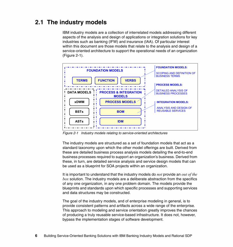
IBM industry models are a collection of interrelated models addressing different aspects of the analysis and design of applications or integration solutions for key industries such as banking (IFW) and insurance (IAA). Of particular interest within this document are those models that relate to the analysis and design of a service-oriented architecture to support the operational needs of an organization (Figure 2-1).
Figure 2-1 Industry models relating to service-oriented architectures
The industry models are structured as a set of foundation models that act as a standard taxonomy upon which the other model offerings are built. Derived from these are detailed business process analysis models detailing the end-to-end business processes required to support an organization’s business. Derived from these, in turn, are detailed service analysis and service design models that can be used as a blueprint for SOA projects within an organization.
It is important to understand that the industry models do not provide an out of the box solution. The industry models are a deliberate abstraction from the specifics of any one organization, in any one problem domain. The models provide the blueprints and standards upon which specific processes and supporting services and data structures may be constructed.
The goal of the industry models, and of enterprise modeling in general, is to provide consistent patterns and artifacts across a wide range of the enterprise. This approach to modeling and service orientation greatly improves the chances of producing a truly reusable service-based infrastructure. It does not, however, bypass the implementation stages of software development.
FOUNDATION MODELS:
SCOPING AND DEFINITION OF BUSINESS TERMS
FOUNDATION MODELS
TERMS FUNCTION VERBS
PROCESS & INTEGRATION MODELS
PROCESS MODELS
BOM
IDM
DATA MODELS
xDWM
BSTs
ASTs
PROCESS MODELS:
DETAILED ANALYSIS OF BUSINESS PROCESSES
INTEGRATION MODELS:
ANALYSIS AND DESIGN OF REUSABLE SERVICES
6 Building Service-Oriented Banking Solutions with IBM Banking Industry Models and Rational SDP
The patterns described within an Interface Design Model (IDM) will provide invaluable guidance to those seeking to expose, for example, the capabilities of existing CICS® transactions as more reusable XML messages, but the task of writing the COBOL code to translate from an ideal XML message into transaction invocations still exists.
Each individual financial institution, and indeed, each individual project within that institution, has a distinct set of challenges relating to the target operating environment. These challenges range from the limitations of existing systems and infrastructure, through to the challenges of the selected solution architecture. The challenges encountered deploying enterprise-wide Web services, for example, differ from the challenges associated with the construction of an enterprise-wide J2EE™ architecture.
The industry models support the identification, analysis, and design of requirements-based solutions, irrespective of the target environment. The technology-based challenges of enterprise integration vary with the selected infrastructure. The challenges of capturing and expressing business requirements and of deriving a service-oriented architecture from these requirements do not. It is the intent of the models to support the requirements-based analysis and design of systems in a way that is not biased by a particular solution architecture. However, capabilities are provided to transform and deploy model artifacts into technology-specific domains, for example, a Business Process Execution Language (BPEL) or J2EE environment.
2.2 Customizing the models
Because the industry models are intended to be customized by an organization, it is reasonable to assume some methodological guidance in doing so. While not seeking to replace the many references detailing the finer points of UML-based analysis and design, the industry models are accompanied by a set of recommendations detailing their usage within SOA-based projects (Figure 2-2).
Chapter 2. IBM Banking Industry Enterprise Models (IFW) overview 7
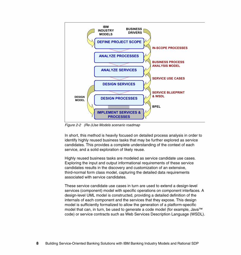
Figure 2-2 (Re-)Use Models scenario roadmap
In short, this method is heavily focused on detailed process analysis in order to identify highly reused business tasks that may be further explored as service candidates. This provides a complete understanding of the context of each service, and a solid exploration of likely reuse.
Highly reused business tasks are modeled as service candidate use cases. Exploring the input and output informational requirements of these service candidates results in the discovery and customization of an extensive, third-normal form class model, capturing the detailed data requirements associated with service candidates.
These service candidate use cases in turn are used to extend a design-level services (component) model with specific operations on component interfaces. A design-level UML model is constructed, providing a detailed definition of the internals of each component and the services that they expose. This design model is sufficiently formalized to allow the generation of a platform-specific model that can, in turn, be used to generate a code model (for example, Java™ code) or service contracts such as Web Services Description Language (WSDL).
DEFINE PROJECT SCOPE
ANALYZE SERVICES
DESIGN SERVICES
DESIGN PROCESSES
IMPLEMENT SERVICES & PROCESSES
ANALYZE PROCESSES
IN-SCOPE PROCESSES
BUSINESS PROCESS ANALYSIS MODEL
SERVICE BLUEPRINT& WSDL
BPEL
SERVICE USE CASES
DESIGNMODEL
IBMINDUSTRYMODELS
BUSINESSDRIVERS
8 Building Service-Oriented Banking Solutions with IBM Banking Industry Models and Rational SDP
2.3 Top-down versus bottom-up
The industry models are well suited to top-down analysis and design, driving service definitions based on pure business requirements. However, few financial institutions today are operating on a rip and replace basis. Most organizations are faced with the challenge of retaining their considerable investment in existing systems. This leads to the motivation to expose the capabilities of existing systems as highly reusable business services.
Clearly, a pure top-down approach is not ideal in this scenario. Considering only pure business requirements is likely to result in service definitions that are impractical or impossible to implement given the constraints of existing systems. This often leads organizations to follow a bottom-up approach, but this too has its own challenges. Heavily biasing service definitions based on the known capabilities of today's systems will certainly yield viable solutions, but will they meet business needs any better than the systems to be integrated already do today?
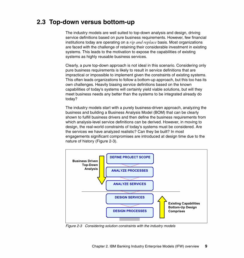
The industry models start with a purely business-driven approach, analyzing the business and building a Business Analysis Model (BOM) that can be clearly shown to fulfill business drivers and then define the business requirements from which analysis-level service definitions can be derived. However, in moving to design, the real-world constraints of today's systems must be considered. Are the services we have analyzed realistic? Can they be built? In most engagements significant compromises are introduced at design time due to the nature of history (Figure 2-3).
Figure 2-3 Considering solution constraints with the industry models
DEFINE PROJECT SCOPE
ANALYZE SERVICES
DESIGN SERVICES
DESIGN PROCESSES
ANALYZE PROCESSES
Existing Capabilities Bottom-Up Design Comprises
Business Driven Top-Down
Analysis
Chapter 2. IBM Banking Industry Enterprise Models (IFW) overview 9

This means that the industry models tend to follow neither a top-down nor a bottom-up approach. Instead, top-down analysis meets solution-focused design. Two quite separate—but traceable—models are maintained: a detailed analysis model based on requirements, and a formalized service design that takes account of constraints of the deployment environment.
10 Building Service-Oriented Banking Solutions with IBM Banking Industry Models and Rational SDP
Chapter 3. Introduction to the IBM Rational Software Delivery Platform
This chapter provides an introduction to the IBM Rational Software Delivery Platform (SDP), which provides the tooling to use IBM Industry Enterprise Models to build service-oriented business solutions.
This chapter is based on an excerpt from:
Building Services-Oriented Solutions with the IBM Software Development Platform, by Alan W. Brown, Distinguished Engineer, IBM Rational Software, August 31, 2004
3
© Copyright IBM Corp. 2007. All rights reserved. 11
3.1 IBM Rational Software Delivery Platform
IBM offers many valuable technologies to help organizations architect, build, deploy, and manage services-oriented solutions. While individual product capabilities are important, the real value to customers is the combination of those capabilities in a robust software development platform for creating this new generation of service-oriented applications. Moreover, the vision being expressed by organizations today is for a set of capabilities for executing IT projects with a level of coordination, accuracy, and clarity rarely obtained today. They are beginning to view software development as a business process that is measurable, predictable, and manageable—a process for which investment in IT resources provides a predictable, risk-managed impact on the business's goals and mission.
This is a compelling vision, and one that can only be delivered through the deep integration of tool and runtime capabilities across all different aspects of the business in support of a services-oriented view of their solutions. In this regard, IBM Rational Software Delivery Platform is a critical step. IBM Rational Software Delivery Platform offers the tooling and technology infrastructure to realize that vision. With respect to SOA and building service-oriented business solutions, IBM Rational Software Delivery Platform addresses five critical needs:
� Bridging the business-to-IT gap. It is essential to align the business view of activities and processes with the technology that is used to realize (parts of) these activities. This alignment includes the ability for business models to drive downstream development, and to evolve the business models and IT solutions in combination. Common design practices are essential to this to ensure that the concepts, artifacts, and activities are synchronized.
� Supporting the changing roles in the IT organization. The move to services thinking changes the skills and composition of teams in an organization. The focus of development moves to identifying, defining, managing, and assembling services, with architectural descriptions highlighting service level agreements (SLAs) and inter-service protocols. The traditional breakdown of tool functions into today's line-up of products is not appropriate to this approach. There will be a different blend of capabilities required by the different members in IT organizations. The skills required by existing roles such as software architect are changing. Similarly, new roles such as business integration specialist are emerging.
� A focus on assets and reuse. Considering services as key assets in the design of systems changes an organization's view of the value of reusing these services. A service assembly viewpoint leads to software factory thinking. As a result, technologies and techniques for management and governance of assets, and repeatable ways to capture patterns for combining
12 Building Service-Oriented Banking Solutions with IBM Banking Industry Models and Rational SDP
assets, become much more important. The team infrastructure for managing assets takes a key role in this approach.
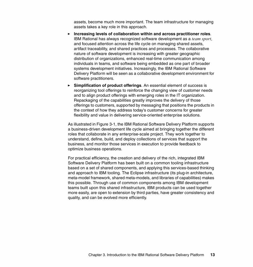
� Increasing levels of collaboration within and across practitioner roles. IBM Rational has always recognized software development as a team sport, and focused attention across the life cycle on managing shared assets, artifact traceability, and shared practices and processes. The collaborative nature of software development is increasing with greater geographic distribution of organizations, enhanced real-time communication among individuals in teams, and software being embedded as one part of broader systems development initiatives. Increasingly, the IBM Rational Software Delivery Platform will be seen as a collaborative development environment for software practitioners.
� Simplification of product offerings. An essential element of success is reorganizing tool offerings to reinforce the changing view of customer needs and to align product offerings with emerging roles in the IT organization. Repackaging of the capabilities greatly improves the delivery of those offerings to customers, supported by messaging that positions the products in the context of how they address today's customer concerns for greater flexibility and value in delivering service-oriented enterprise solutions.
As illustrated in Figure 3-1, the IBM Rational Software Delivery Platform supports a business-driven development life cycle aimed at bringing together the different roles that collaborate in any enterprise-scale project. They work together to understand, define, build, and deploy collections of services that support the business, and monitor those services in execution to provide feedback to optimize business operations.
For practical efficiency, the creation and delivery of the rich, integrated IBM Software Delivery Platform has been built on a common tooling infrastructure based on a set of shared components, and applying this services-based thinking and approach to IBM tooling. The Eclipse infrastructure (its plug-in architecture, meta-model framework, shared meta-models, and libraries of capabilities) makes this possible. Through use of common components among IBM development teams built upon this shared infrastructure, IBM products can be used together more easily, are open to extension by third parties, have greater consistency and quality, and can be evolved more efficiently.
Chapter 3. Introduction to the IBM Rational Software Delivery Platform 13
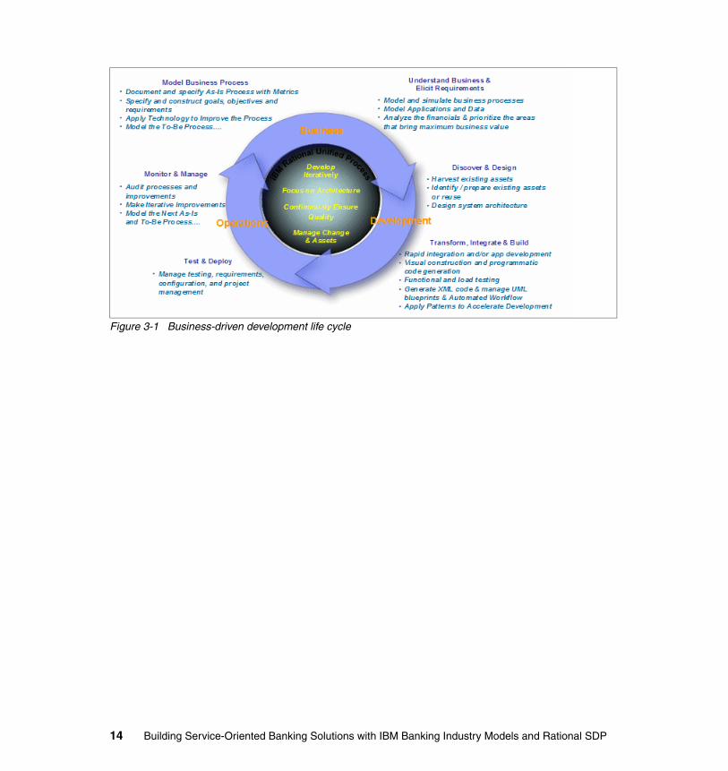
Figure 3-1 Business-driven development life cycle
14 Building Service-Oriented Banking Solutions with IBM Banking Industry Models and Rational SDP
Chapter 4. Introduction to creating service-oriented business solutions for the financial services sector
This chapter provides an introduction and an overview to creating service-oriented business solutions using IBM Industry Enterprise Models—specifically banking (IFW)—and the Software Delivery Platform (SDP).
4
© Copyright IBM Corp. 2007. All rights reserved. 15

4.1 Overview of creating service-oriented business solutions for the financial services sector
Businesses care primarily about creating and growing market share and profitability. They do this, in part, by continuously adjusting their business priorities and evolving their business model, business and supporting IT architectures to meet or capitalize on ever changing market conditions—and are always looking for better (more efficient, effective) ways to do this. The IBM Banking Industry Enterprise models (IFW) and SDP can be used together by the business to drive development of service oriented business solutions to directly deliver against business priorities—this is a core value proposition of what IBM has characterized as business-driven development.
The (Re-)Use Enterprise Models usage scenario (illustrated in Figure 4-1) is a high-level description of the orchestration of key activities, roles, artifacts and supporting offerings from IBM that are necessary to continuously evolve the enterprise's business and IT architectures to fulfill its ever changing business priorities. This scenario description leverages and extends the IBM Rational Unified Process® (RUP®) and Service-Oriented Methodology and Architecture (RUP SOMA) process, activity, and role content and utilizes the IBM Banking Industry Enterprise Models (IFW) and Software Delivery Platform (SDP).
Figure 4-1 (Re-)Use Enterprise Models usage scenario
ModelManager
BusinessAnalyst
Analyze Processes
Manage and Govern Enterprise Models
IBM Industry Models
BusinessDrivers
Service/DataAnalyst
Service/DataDesigner
Analyze Services
Design Services
Define Project Scope
Integration/DataDeveloper
Design Processes
Supporting Offerings1. Rational
RequisitePro2. WebSphere Business
Modeler3. IBM Industry Models
& RSA plug-ins, profiles
Supporting Offerings1. Rational
RequisitePro2. Rational Software
Architect3. IBM Industry Models
& RSA plug-ins, profiles
Supporting Offerings1. Rational Software
Architect2. IBM Industry Models
& RSA plug-ins, profiles
Supporting Offerings1. WebSphere Business
Modeler2. WebSphere
Integration Developer
Analyze Data Define Logical Data Model
Define Physical Data
ModelsDefine
Datastores
16 Building Service-Oriented Banking Solutions with IBM Banking Industry Models and Rational SDP
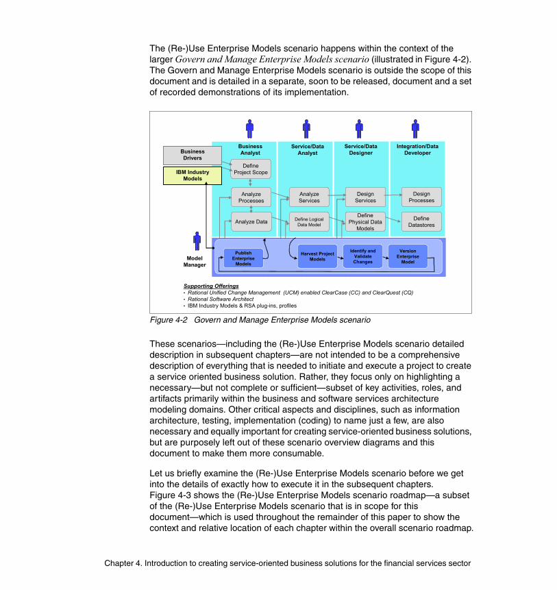
The (Re-)Use Enterprise Models scenario happens within the context of the larger Govern and Manage Enterprise Models scenario (illustrated in Figure 4-2). The Govern and Manage Enterprise Models scenario is outside the scope of this document and is detailed in a separate, soon to be released, document and a set of recorded demonstrations of its implementation.
Figure 4-2 Govern and Manage Enterprise Models scenario
These scenarios—including the (Re-)Use Enterprise Models scenario detailed description in subsequent chapters—are not intended to be a comprehensive description of everything that is needed to initiate and execute a project to create a service oriented business solution. Rather, they focus only on highlighting a necessary—but not complete or sufficient—subset of key activities, roles, and artifacts primarily within the business and software services architecture modeling domains. Other critical aspects and disciplines, such as information architecture, testing, implementation (coding) to name just a few, are also necessary and equally important for creating service-oriented business solutions, but are purposely left out of these scenario overview diagrams and this document to make them more consumable.
Let us briefly examine the (Re-)Use Enterprise Models scenario before we get into the details of exactly how to execute it in the subsequent chapters. Figure 4-3 shows the (Re-)Use Enterprise Models scenario roadmap—a subset of the (Re-)Use Enterprise Models scenario that is in scope for this document—which is used throughout the remainder of this paper to show the context and relative location of each chapter within the overall scenario roadmap.
BusinessAnalyst
Analyze Processes
IBM Industry Models
BusinessDrivers
Service/DataAnalyst
Analyze Data Define Logical Data Model
Analyze Services
Define Physical Data
Models
Design Services
Define Project Scope
Define Datastores
Design Processes
ModelManager
Publish Enterprise
Models
Harvest Project Models
Identify and Validate Changes
Version Enterprise
Model
Supporting Offerings• Rational Unified Change Management (UCM) enabled ClearCase (CC) and ClearQuest (CQ)• Rational Software Architect• IBM Industry Models & RSA plug-ins, profiles
Integration/DataDeveloper
Service/DataDesigner
Chapter 4. Introduction to creating service-oriented business solutions for the financial services sector
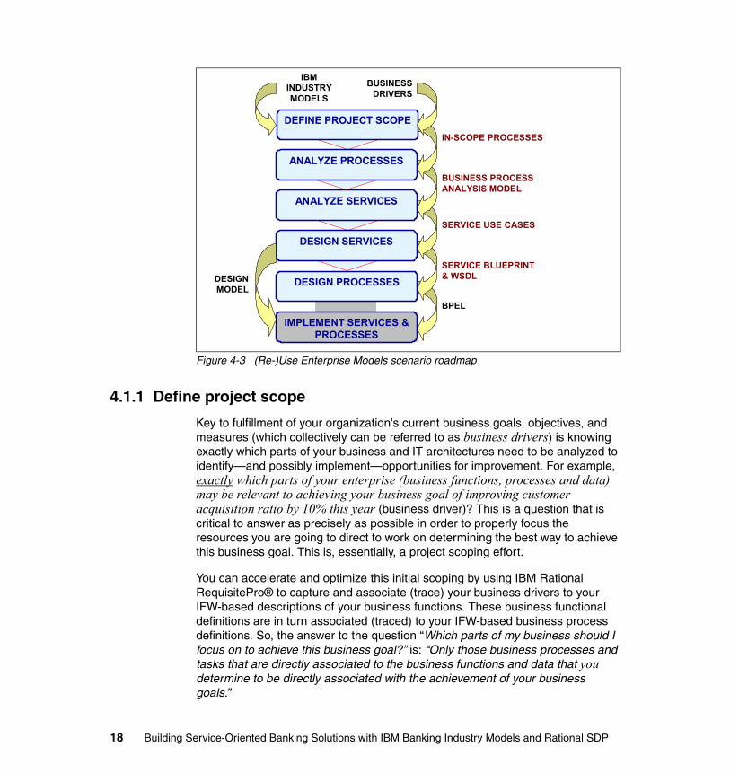
Figure 4-3 (Re-)Use Enterprise Models scenario roadmap
4.1.1 Define project scope
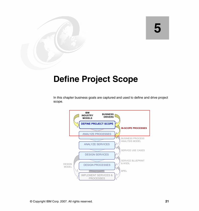
Key to fulfillment of your organization's current business goals, objectives, and measures (which collectively can be referred to as business drivers) is knowing exactly which parts of your business and IT architectures need to be analyzed to identify—and possibly implement—opportunities for improvement. For example, exactly which parts of your enterprise (business functions, processes and data) may be relevant to achieving your business goal of improving customer acquisition ratio by 10% this year (business driver)? This is a question that is critical to answer as precisely as possible in order to properly focus the resources you are going to direct to work on determining the best way to achieve this business goal. This is, essentially, a project scoping effort.
You can accelerate and optimize this initial scoping by using IBM Rational RequisitePro® to capture and associate (trace) your business drivers to your IFW-based descriptions of your business functions. These business functional definitions are in turn associated (traced) to your IFW-based business process definitions. So, the answer to the question “Which parts of my business should I focus on to achieve this business goal?” is: “Only those business processes and tasks that are directly associated to the business functions and data that you determine to be directly associated with the achievement of your business goals.”
DEFINE PROJECT SCOPE
ANALYZE SERVICES
DESIGN SERVICES
DESIGN PROCESSES
IMPLEMENT SERVICES & PROCESSES
ANALYZE PROCESSES
IN-SCOPE PROCESSES
BUSINESS PROCESS ANALYSIS MODEL
SERVICE BLUEPRINT& WSDL
BPEL
SERVICE USE CASES
DESIGNMODEL
IBMINDUSTRYMODELS
BUSINESSDRIVERS
18 Building Service-Oriented Banking Solutions with IBM Banking Industry Models and Rational SDP
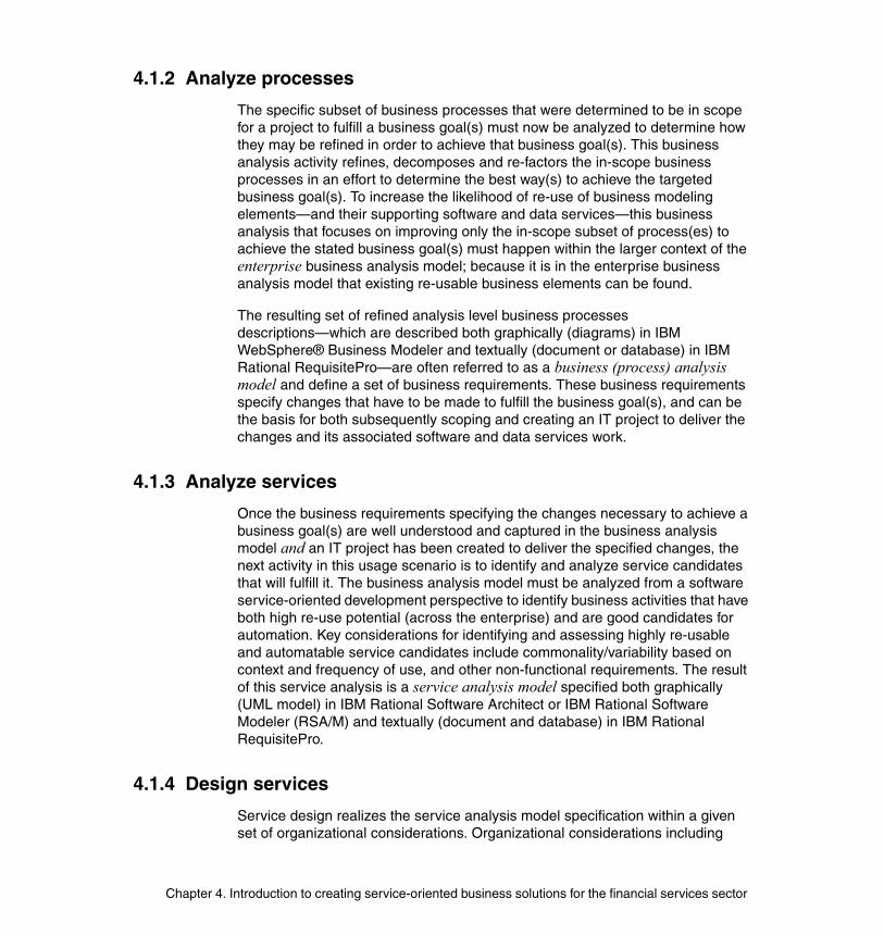
4.1.2 Analyze processes
The specific subset of business processes that were determined to be in scope for a project to fulfill a business goal(s) must now be analyzed to determine how they may be refined in order to achieve that business goal(s). This business analysis activity refines, decomposes and re-factors the in-scope business processes in an effort to determine the best way(s) to achieve the targeted business goal(s). To increase the likelihood of re-use of business modeling elements—and their supporting software and data services—this business analysis that focuses on improving only the in-scope subset of process(es) to achieve the stated business goal(s) must happen within the larger context of the enterprise business analysis model; because it is in the enterprise business analysis model that existing re-usable business elements can be found.
The resulting set of refined analysis level business processes descriptions—which are described both graphically (diagrams) in IBM WebSphere® Business Modeler and textually (document or database) in IBM Rational RequisitePro—are often referred to as a business (process) analysis model and define a set of business requirements. These business requirements specify changes that have to be made to fulfill the business goal(s), and can be the basis for both subsequently scoping and creating an IT project to deliver the changes and its associated software and data services work.
4.1.3 Analyze services
Once the business requirements specifying the changes necessary to achieve a business goal(s) are well understood and captured in the business analysis model and an IT project has been created to deliver the specified changes, the next activity in this usage scenario is to identify and analyze service candidates that will fulfill it. The business analysis model must be analyzed from a software service-oriented development perspective to identify business activities that have both high re-use potential (across the enterprise) and are good candidates for automation. Key considerations for identifying and assessing highly re-usable and automatable service candidates include commonality/variability based on context and frequency of use, and other non-functional requirements. The result of this service analysis is a service analysis model specified both graphically (UML model) in IBM Rational Software Architect or IBM Rational Software Modeler (RSA/M) and textually (document and database) in IBM Rational RequisitePro.
4.1.4 Design services
Service design realizes the service analysis model specification within a given set of organizational considerations. Organizational considerations including
Chapter 4. Introduction to creating service-oriented business solutions for the financial services sector

existing business and technical architecture, and project constraints force compromises to be made to the service analysis model. The resultant UML service design model in IBM Rational Software Architect or Modeler represents the set of comprises made to the service analysis model that provides the basis for subsequent service implementation and, optionally, process design and implementation activities.
4.1.5 Design processes
The process design activity refines the IFW based business (process) analysis model based on the service and other design models, as well as compromises that must be made for the targeted managed process run-time platform. IBM WebSphere Business Modeler is used for this activity. Process design is a set of steps that have to be undertaken to design a business process that is intended to be implemented and deployed to an executable and managed business process runtime environment. The process design model will most often differ considerably from the structure of the process analysis model but not in business intent.
4.1.6 Implement services and processes
Service and process implementation are the activities that take the results of service and process design one step closer to solution delivery. While the details of these activities are not within the scope of this paper, it is important to acknowledge that these are the next set of key activities in the creation of a service oriented business solution.
Service implementation can be done using IBM Rational Software Architect (RSA) to transform the software service design model, including the IFW Interface and Java Design Models (IDM and JDM), into a Java based implementation. The design model is used to specify and accelerate this effort including development of Java and J2EE components including java classes that are used to implement core J2EE design patterns and constructs such as data transfer objects, session facades, and domain objects. Alternative tooling combinations to support this activity include a mix of IBM Rational Software Modeler, Rational Application Developer, and Rational Software Architect.
Process implementation uses the BPEL exported from the Process Design Model and the WSDL exported from Interface Design Model to implement a process to be deployed to a managed and monitored workflow runtime platform. This step is performed with IBM WebSphere Integration Developer (WID).
20 Building Service-Oriented Banking Solutions with IBM Banking Industry Models and Rational SDP
Chapter 5. Define Project Scope
In this chapter business goals are captured and used to define and drive project scope.
5
DEFINE PROJECT SCOPE
ANALYZE SERVICES
DESIGN SERVICES
DESIGN PROCESSES
IMPLEMENT SERVICES & PROCESSES
ANALYZE PROCESSES
IN-SCOPE PROCESSES
BUSINESS PROCESS ANALYSIS MODEL
SERVICE BLUEPRINT& WSDL
BPEL
SERVICE USE CASES
DESIGNMODEL
IBMINDUSTRYMODELS
BUSINESSDRIVERS
© Copyright IBM Corp. 2007. All rights reserved. 21
5.1 Introduction to define Project Scope1
One of the primary goals of business-driven development and IBM Industry Models is to align and link IT goals and projects with business goals. Business-driven development asserts that the motivation for business and IT projects should be to fulfill specific business goals and objectives, and this relationship between projects and business goals should be explicit and traceable across the different phases of a project life cycle. IBM Industry Model content can be used to facilitate and accelerate fulfillment of this goal of improved and more effective business-IT alignment.
5.2 Using IBM Rational SDP to define Project Scope
In this chapter we show how an organization can use IBM Rational SDP, including a predefined IFW Rational RequisitePro project template to capture its business goals, and then use those business goals to drive and scope downstream activities including those detailed in this paper. This chapter includes the following steps:
� Capture business goals—Capture enterprise business goals, objectives, and other business requirements in a way that they can be used and re-used to drive business and IT projects.
� Determine business functional scope—Examine the existing IFW Financial Services Function Model (FSFM) and decide which functional areas to focus on to achieve the stated business goals.
� Identify and prioritize in-scope business processes—Determine which IFW-based business processes are in-scope to fulfill a given set of business goals and requirements.
The following IBM Rational SDP products and capabilities are used in this chapter:
� IBM Rational RequisitePro: An easy-to-use requirements and use case management tool for teams that want to improve the communication of project goals, reduce project risk, and increase the quality of applications before deployment. The IBM Rational RequisitePro solution lets teams author and share their requirements using familiar document-based methods, while leveraging database-enabled capabilities, such as requirements traceability and impact analysis. The result is better communication and management of
1 Notes: 1) Additional methodological guidance/motivation is available in the IM&A Model Customization Roadmap. 2) Detailed IM&A modeling guidelines for WBM and RSx are available in the IM&A Process and Service Models Metamodel Guide and other related publications. These publications are available to licensees of the IBM Industry Models. Send an e-mail to [email protected] to ask for access.
22 Building Service-Oriented Banking Solutions with IBM Banking Industry Models and Rational SDP

both business and technical requirements with the increased likelihood of completing projects on time, within budget, and above expectations.
� Requirements stored and managed in RequisitePro can be accessed and associated to corresponding RSA/M UML modeling elements and synchronized with user-selectable rules. This integration is used extensively throughout the approach described in this paper. As you will see, we have used this integration to automatically create and link RequisitePro requirements to the IFW Process Model and Business Object Model elements in Rational Software Architect and Rational Software Modeler.
� IBM Rational Software Modeler (RSM™): While not explicitly used in this chapter, the aforementioned integration with RequisitePro was used to populate the RequisitePro project with IFW Process Model content. RSM is a Unified Modeling Language (UML) 2.0-based visual modeling and design tool for architects, analysts, and designers who have to ensure that their specifications, architectures, and designs are clearly defined and communicated. RSM is also part of the flexible family of business-driven development products that constitute the SDP, which is built on the open Eclipse integration platform. RSM provides a sub-set of the capabilities of Rational Software Architect (RSA)—it does not include the Rational Application Developer (RAD) components—and, as such, can be used by analysts and designers who do not need the additional (primarily RAD-based code development) capabilities provided by RSA. Henceforth, we refer to RSA and RSM interchangeably or with a RSA/M notation.
� Projects like those described in this paper also require management of changes to the models and other life cycle artifacts. RSA/M and RequisitePro, as integrated parts of the IBM Rational SDP, are also integrated with other SDP tooling that support other parts of the SOA life cycle, including IBM Rational ClearCase® and IBM Rational ClearQuest®, robust configuration and change management IBM product families. Governance and management of the Industry Models is detailed in another, soon to be published, paper (contact [email protected] for the latest information regarding the status of this paper).
5.3 Capture business goals2
The first step is to capture the existing business goals in RequisitePro. These business goals can be entered by using the predefined view named All Business Goals within the IFW RequisitePro template. This view is located in the Business Drivers → Business Goals package.
2 Refer to Appendix B, “Modeling project setup and management” on page 191, for instructions on how to create a new RequisitePro project utilizing the IFW RequisitePro project template. Refer to the RequisitePro Help documentation, especially Let's Go RequisitePro, Quick Tour, and Tutorial, for an introduction to RequisitePro and how to use it.
Chapter 5. Define Project Scope 23

Figure 5-1 shows the All Business Goals view (and its location) within RequisitePro.
Figure 5-1 Capture business goals
Attribute values, such as priority and status, for each business goal can also be captured at this time. Attributes can be used to help manage information by, for example, enabling easy sorting or filtering of business goals (or any record/requirement type) based on their priority, status, or user-defined attribute values. RequisitePro can be used to create any type of record (requirement) or associated record attributes.
5.4 Determine business functional scope
In this section we determine and establish a traceability relationship between an organization's business goals and the business functions that need to be part of any projects responsible for their fulfillment. This business goal/business function relationship is very useful for identifying and determining a project's scope with respect to the business functional area. Candidate projects and their business functional scopes are determined by analyzing: (1) business goal attributes (like priority, stability), (2) establishing and analyzing business goals relationships to business functional areas, and (3) existing projects and the goals with which they are associated and their scope.
The approach we use in this paper (optionally) utilizes IFW's Financial Services Function Model (FSFM), which is a comprehensive, hierarchical decomposition of a bank's business functional areas. Other business functional classification frameworks can be used in lieu of FSFM, or, as layers above the FSFM. For example, IBM Global Business Services' Banking Component Business Model™
24 Building Service-Oriented Banking Solutions with IBM Banking Industry Models and Rational SDP
(CBM) or some other enterprise business functional framework could also be used to unambiguously define the project's scope with respect to business functional areas.
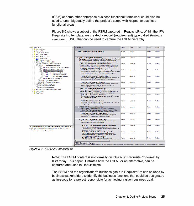
Figure 5-2 shows a subset of the FSFM captured in RequisitePro. Within the IFW RequisitePro template, we created a record (requirement) type called Business Function (FUNC) that can be used to capture the FSFM hierarchy.
Figure 5-2 FSFM in RequisitePro
Note: The FSFM content is not formally distributed in RequisitePro format by IFW today. This paper illustrates how the FSFM, or an alternative, can be captured and used in RequisitePro.
The FSFM and the organization's business goals in RequisitePro can be used by business stakeholders to identify the business functions that could be designated as in-scope for a project responsible for achieving a given business goal.
Chapter 5. Define Project Scope 25

5.4.1 Establish relationship between business goals and business functional areas
For each of the business goals that have been captured, RequisitePro may be used to create formal traceability or trace) relationships between business goals and business functions. We establish this trace relationship for each of the captured business goals in our example.3
Figure 5-3 shows the Business Goals to Business Functions RequisitePro traceability matrix, its location in the project tree, and how to create a traceability relationship between the two types of records—business goals and functions—shown in the traceability matrix view.
A RequisitePro traceability matrix shows the traceability relationships between two different record types—one on each axis, row, and column. To signify that a business goal is related to a business function, create a Trace To relationship entry at the intersection in the matrix for that pair.
3 There are two types of relationships that can be captured with RequisitePro: hierarchal and traceability. Relationships between information of the same type (same requirement type) can be established in RequisitePro through hierarchical relationships. For example, a business function (parent) may be decomposed into sub-functions (children). These subordinate functional areas are captured as children of the super-ordinate/parent (this is the approach that has been implemented in this RequisitePro project). Relationships between different types of information are captured through RequisitePro traceability relationships.
26 Building Service-Oriented Banking Solutions with IBM Banking Industry Models and Rational SDP
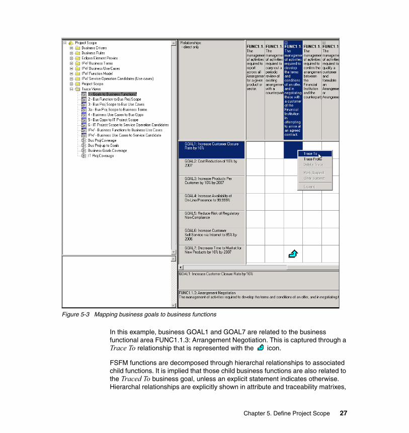
Figure 5-3 Mapping business goals to business functions
In this example, business GOAL1 and GOAL7 are related to the business functional area FUNC1.1.3: Arrangement Negotiation. This is captured through a Trace To relationship that is represented with the icon.
FSFM functions are decomposed through hierarchal relationships to associated child functions. It is implied that those child business functions are also related to the Traced To business goal, unless an explicit statement indicates otherwise. Hierarchal relationships are explicitly shown in attribute and traceability matrixes,
Chapter 5. Define Project Scope 27
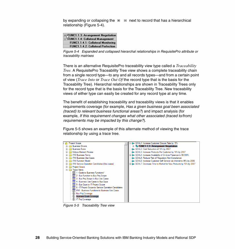
by expanding or collapsing the next to record that has a hierarchical relationship (Figure 5-4).
Figure 5-4 Expanded and collapsed hierarchal relationships in RequisitePro attribute or traceability matrixes
There is an alternative RequisitePro traceability view type called a Traceability Tree. A RequisitePro Traceability Tree view shows a complete traceability chain from a single record type—to any and all records types—and from a certain point of view (Trace Into or Trace Out Of the record type that is the basis for the Traceability Tree). Hierarchal relationships are shown in Traceability Trees only for the record type that is the basis for the Traceability Tree. New traceability views of either type can easily be created for any record type at any time.
The benefit of establishing traceability and traceability views is that it enables requirements coverage (for example, Has a given business goal been associated (traced) to relevant business functional areas?) and impact analysis (for example, If this requirement changes what other associated (traced to/from) requirements may be impacted by this change?).
Figure 5-5 shows an example of this alternate method of viewing the trace relationship by using a trace tree.
Figure 5-5 Traceability Tree view
28 Building Service-Oriented Banking Solutions with IBM Banking Industry Models and Rational SDP
5.4.2 Specify which business goals and business functional areas are candidates to be in-scope for a new project
The purpose of this step is to specify which business goals and business functions are candidates to be in-scope for a new project. This is accomplished using the previously established business goal to function traceability relationships. Analyze these relationships using the business goal and business function attributes—like priority and status—to define the project's candidate business scope.
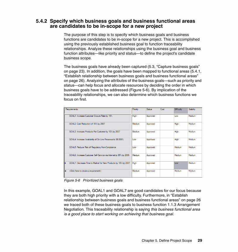
The business goals have already been captured (5.3, “Capture business goals” on page 23). In addition, the goals have been mapped to functional areas (5.4.1, “Establish relationship between business goals and business functional areas” on page 26). Analyzing the attributes of the business goals—such as priority and status—can help focus and allocate resources by deciding the order in which business goals have to be addressed (Figure 5-6). By implication of the traceability relationships, we can also determine which business functions we focus on first.
Figure 5-6 Prioritized business goals
In this example, GOAL1 and GOAL7 are good candidates for our focus because they are both high priority with a low difficulty. Furthermore, in “Establish relationship between business goals and business functional areas” on page 26 we traced both of these business goals to business function 1.1.3 Arrangement Negotiation. This traceability relationship is saying this business functional area is a good place to start working on achieving that business goal.
Chapter 5. Define Project Scope 29
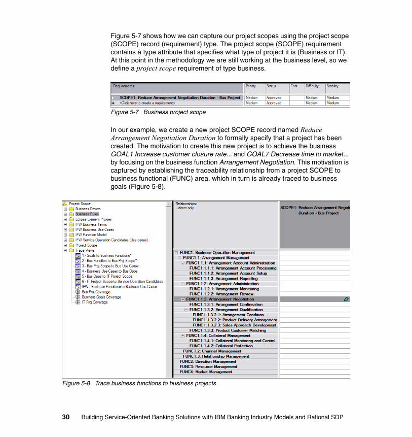
Figure 5-7 shows how we can capture our project scopes using the project scope (SCOPE) record (requirement) type. The project scope (SCOPE) requirement contains a type attribute that specifies what type of project it is (Business or IT). At this point in the methodology we are still working at the business level, so we define a project scope requirement of type business.
Figure 5-7 Business project scope
In our example, we create a new project SCOPE record named Reduce Arrangement Negotiation Duration to formally specify that a project has been created. The motivation to create this new project is to achieve the business GOAL1 Increase customer closure rate... and GOAL7 Decrease time to market... by focusing on the business function Arrangement Negotiation. This motivation is captured by establishing the traceability relationship from a project SCOPE to business functional (FUNC) area, which in turn is already traced to business goals (Figure 5-8).
Figure 5-8 Trace business functions to business projects
30 Building Service-Oriented Banking Solutions with IBM Banking Industry Models and Rational SDP
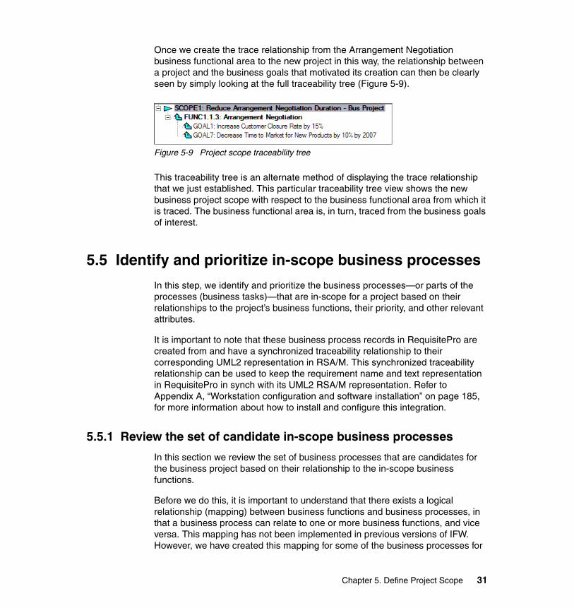
Once we create the trace relationship from the Arrangement Negotiation business functional area to the new project in this way, the relationship between a project and the business goals that motivated its creation can then be clearly seen by simply looking at the full traceability tree (Figure 5-9).
Figure 5-9 Project scope traceability tree
This traceability tree is an alternate method of displaying the trace relationship that we just established. This particular traceability tree view shows the new business project scope with respect to the business functional area from which it is traced. The business functional area is, in turn, traced from the business goals of interest.
5.5 Identify and prioritize in-scope business processes
In this step, we identify and prioritize the business processes—or parts of the processes (business tasks)—that are in-scope for a project based on their relationships to the project’s business functions, their priority, and other relevant attributes.
It is important to note that these business process records in RequisitePro are created from and have a synchronized traceability relationship to their corresponding UML2 representation in RSA/M. This synchronized traceability relationship can be used to keep the requirement name and text representation in RequisitePro in synch with its UML2 RSA/M representation. Refer to Appendix A, “Workstation configuration and software installation” on page 185, for more information about how to install and configure this integration.
5.5.1 Review the set of candidate in-scope business processes
In this section we review the set of business processes that are candidates for the business project based on their relationship to the in-scope business functions.
Before we do this, it is important to understand that there exists a logical relationship (mapping) between business functions and business processes, in that a business process can relate to one or more business functions, and vice versa. This mapping has not been implemented in previous versions of IFW. However, we have created this mapping for some of the business processes for
Chapter 5. Define Project Scope 31
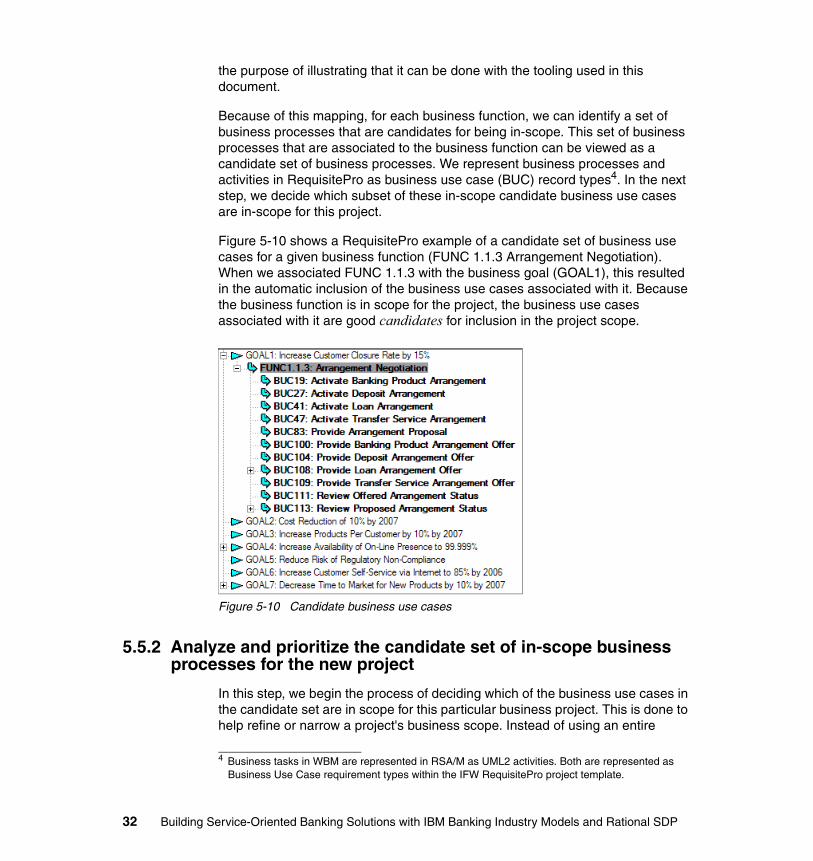
the purpose of illustrating that it can be done with the tooling used in this document.
Because of this mapping, for each business function, we can identify a set of business processes that are candidates for being in-scope. This set of business processes that are associated to the business function can be viewed as a candidate set of business processes. We represent business processes and activities in RequisitePro as business use case (BUC) record types4. In the next step, we decide which subset of these in-scope candidate business use cases are in-scope for this project.
Figure 5-10 shows a RequisitePro example of a candidate set of business use cases for a given business function (FUNC 1.1.3 Arrangement Negotiation). When we associated FUNC 1.1.3 with the business goal (GOAL1), this resulted in the automatic inclusion of the business use cases associated with it. Because the business function is in scope for the project, the business use cases associated with it are good candidates for inclusion in the project scope.
Figure 5-10 Candidate business use cases
5.5.2 Analyze and prioritize the candidate set of in-scope business processes for the new project
In this step, we begin the process of deciding which of the business use cases in the candidate set are in scope for this particular business project. This is done to help refine or narrow a project's business scope. Instead of using an entire
4 Business tasks in WBM are represented in RSA/M as UML2 activities. Both are represented as Business Use Case requirement types within the IFW RequisitePro project template.
32 Building Service-Oriented Banking Solutions with IBM Banking Industry Models and Rational SDP
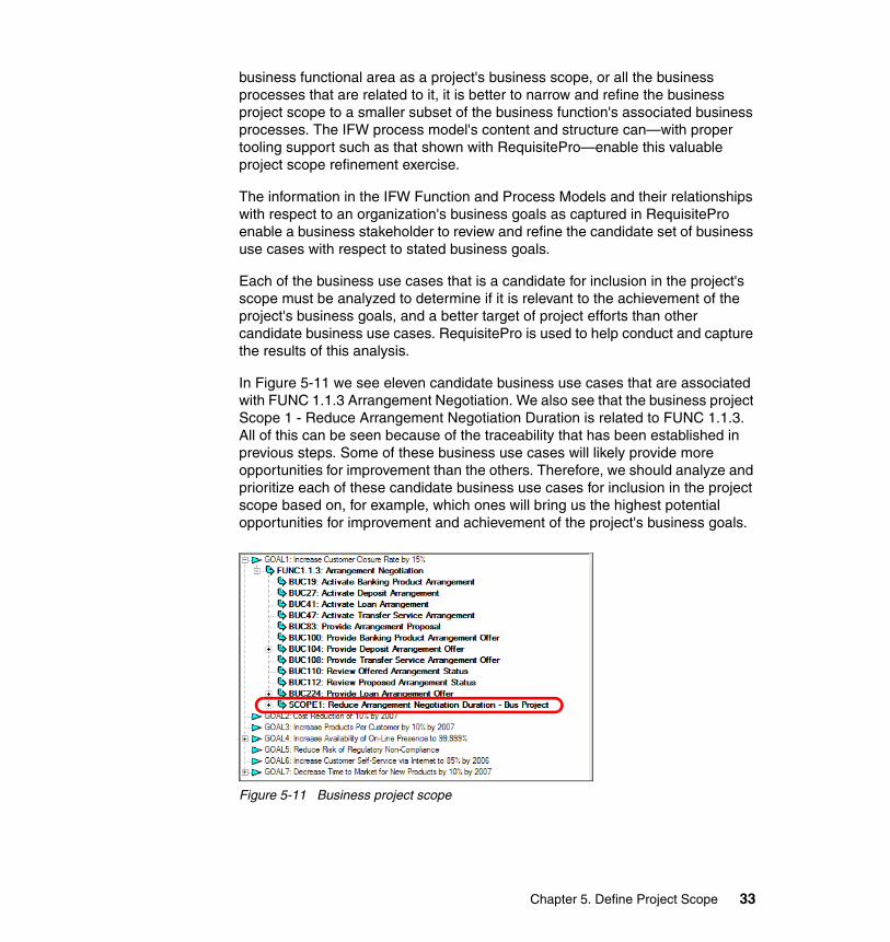
business functional area as a project's business scope, or all the business processes that are related to it, it is better to narrow and refine the business project scope to a smaller subset of the business function's associated business processes. The IFW process model's content and structure can—with proper tooling support such as that shown with RequisitePro—enable this valuable project scope refinement exercise.
The information in the IFW Function and Process Models and their relationships with respect to an organization's business goals as captured in RequisitePro enable a business stakeholder to review and refine the candidate set of business use cases with respect to stated business goals.
Each of the business use cases that is a candidate for inclusion in the project's scope must be analyzed to determine if it is relevant to the achievement of the project's business goals, and a better target of project efforts than other candidate business use cases. RequisitePro is used to help conduct and capture the results of this analysis.
In Figure 5-11 we see eleven candidate business use cases that are associated with FUNC 1.1.3 Arrangement Negotiation. We also see that the business project Scope 1 - Reduce Arrangement Negotiation Duration is related to FUNC 1.1.3. All of this can be seen because of the traceability that has been established in previous steps. Some of these business use cases will likely provide more opportunities for improvement than the others. Therefore, we should analyze and prioritize each of these candidate business use cases for inclusion in the project scope based on, for example, which ones will bring us the highest potential opportunities for improvement and achievement of the project's business goals.
Figure 5-11 Business project scope
Chapter 5. Define Project Scope 33
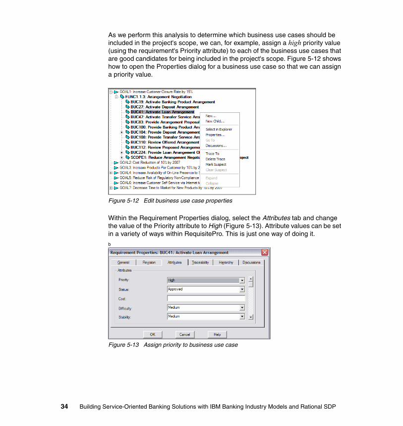
As we perform this analysis to determine which business use cases should be included in the project's scope, we can, for example, assign a high priority value (using the requirement's Priority attribute) to each of the business use cases that are good candidates for being included in the project's scope. Figure 5-12 shows how to open the Properties dialog for a business use case so that we can assign a priority value.
Figure 5-12 Edit business use case properties
Within the Requirement Properties dialog, select the Attributes tab and change the value of the Priority attribute to High (Figure 5-13). Attribute values can be set in a variety of ways within RequisitePro. This is just one way of doing it.
b
Figure 5-13 Assign priority to business use case
34 Building Service-Oriented Banking Solutions with IBM Banking Industry Models and Rational SDP
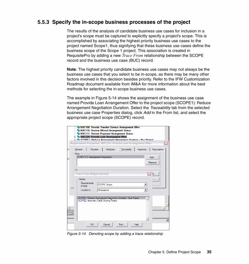
5.5.3 Specify the in-scope business processes of the project
The results of the analysis of candidate business use cases for inclusion in a project's scope must be captured to explicitly specify a project's scope. This is accomplished by associating the highest priority business use cases to the project named Scope1, thus signifying that these business use cases define the business scope of the Scope 1 project. This association is created in RequisitePro by adding a new Trace From relationship between the SCOPE record and the business use case (BUC) record.
Note: The highest priority candidate business use cases may not always be the business use cases that you select to be in-scope, as there may be many other factors involved in this decision besides priority. Refer to the IFW Customization Roadmap document available from IM&A for more information about the best methods for selecting the in-scope business use cases.
The example in Figure 5-14 shows the assignment of the business use case named Provide Loan Arrangement Offer to the project scope (SCOPE1): Reduce Arrangement Negotiation Duration. Select the Traceability tab from the selected business use case Properties dialog, click Add in the From list, and select the appropriate project scope (SCOPE) record.
Figure 5-14 Denoting scope by adding a trace relationship
Chapter 5. Define Project Scope 35
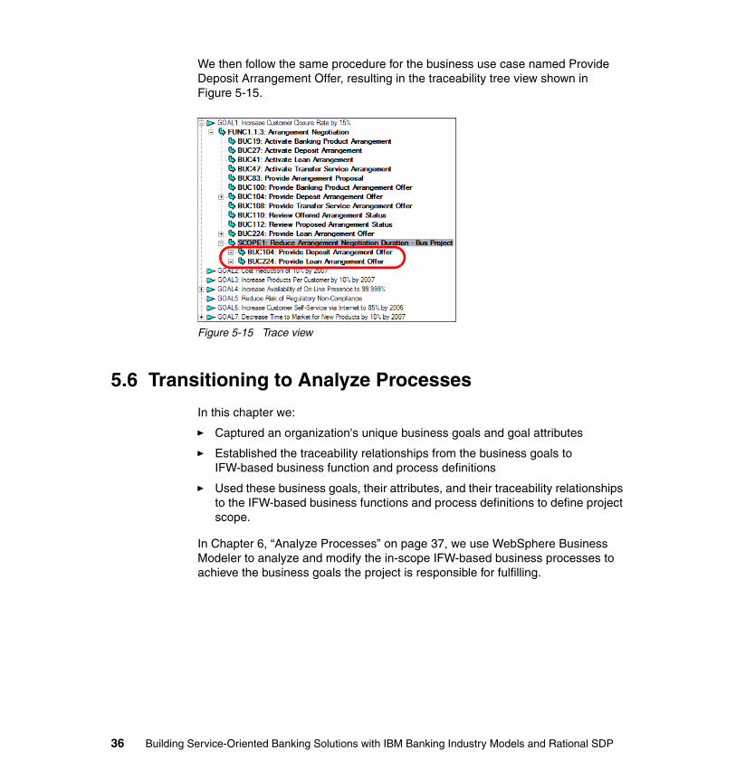
We then follow the same procedure for the business use case named Provide Deposit Arrangement Offer, resulting in the traceability tree view shown in Figure 5-15.
Figure 5-15 Trace view
5.6 Transitioning to Analyze Processes
In this chapter we:
� Captured an organization's unique business goals and goal attributes
� Established the traceability relationships from the business goals to IFW-based business function and process definitions
� Used these business goals, their attributes, and their traceability relationships to the IFW-based business functions and process definitions to define project scope.
In Chapter 6, “Analyze Processes” on page 37, we use WebSphere Business Modeler to analyze and modify the in-scope IFW-based business processes to achieve the business goals the project is responsible for fulfilling.
36 Building Service-Oriented Banking Solutions with IBM Banking Industry Models and Rational SDP
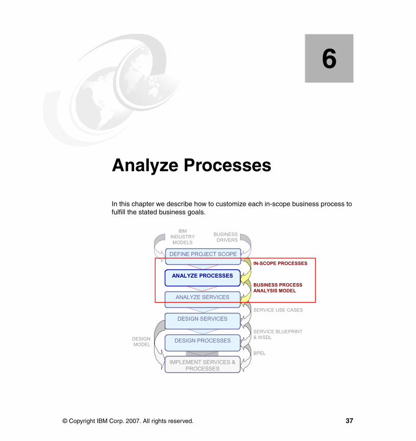
Chapter 6. Analyze Processes
In this chapter we describe how to customize each in-scope business process to fulfill the stated business goals.
6
DEFINE PROJECT SCOPE
ANALYZE SERVICES
DESIGN SERVICES
DESIGN PROCESSES
IMPLEMENT SERVICES & PROCESSES
ANALYZE PROCESSES
IN-SCOPE PROCESSES
BUSINESS PROCESS ANALYSIS MODEL
SERVICE BLUEPRINT& WSDL
BPEL
SERVICE USE CASES
DESIGNMODEL
IBMINDUSTRYMODELS
BUSINESSDRIVERS
© Copyright IBM Corp. 2007. All rights reserved. 37
6.1 Introduction to Analyze Processes1
Analyzing business processes involves examination of a number of aspects of the process as a whole, the context of the process, and the constituent elements of that process. This is done by iteratively identifying and refining the following areas:
� Specify business process resources (business systems, services, and roles) that perform the business process.
� Specify business process elements including tasks, decisions, and control and business information (WebSphere Business Modeler business items) flow logic.
� Specify allocation of the responsibilities for the business process tasks to business roles.
� Specify associated business functional and non-functional requirements, including business rules.
Business processes can be described graphically using diagrams or textually. The approach detailed in this paper combines graphical and textual descriptions of the business processes and their context as the basis for a complete set of business requirements that need to be fulfilled—often referred to as a business (process) analysis model. The business analysis model includes both functional and non-functional business requirements. Non-functional requirements include business rules, regulations, and business measures including performance and reliability that can apply to a single process or element, or an entire set of processes or functional areas. This paper provides detailed guidance on capturing, managing, and using business process specific requirements.
It is important to note that the steps in this section—and, indeed, throughout this paper—are described as discrete steps with an implied time-ordered sequencing. In fact, these steps should be executed in an iterative manner, blurring the boundaries between the steps. Experienced practitioners usually blend these discrete steps into a seamless, yet different aspect of the analyze processes activity.
1 Notes: 1) Additional methodological guidance/motivation is available in the IM&A Model Customization Roadmap. 2) Detailed IM&A modeling guidelines for WBM and RSx are available in the IM&A Process and Service Models Metamodel Guide and other related publications. These publications are available to licensees of the IBM Industry Models. Send an e-mail to [email protected] to ask for access.
38 Building Service-Oriented Banking Solutions with IBM Banking Industry Models and Rational SDP
6.2 Using IBM Rational SDP to Analyze Processes
Most of the activities in this chapter are performed using IBM WebSphere Business Modeler (WBM). Up to this point in this paper, the discussion of how to use the industry models to define project scope has focused on how to use them with RequisitePro. The enterprise copy of the process model artifacts is maintained in RSA/M and the Eclipse SCM compliant configuration management repository. WBM is the IBM process analysis tool for business stakeholders, and is used to perform the graphical process modeling. WBM helps to bridge the gap between line of business and IT by providing robust functionality for modeling of business processes, essential business data and artifacts, organization, structure, resources, time line and location, in support of the business process analysis activity. Equally important, WBM process models can be (re-)used for requirements, software, and data modeling because of its integration with other SDP modeling tools.
We use IBM Rational RequisitePro in this chapter to compliment WBM's graphical process modeling-based capabilities by:
� Textually describing the business process and its elements.
� Capturing, managing, and using the results of the business process analysis to drive subsequent life cycle activities. This includes capturing the business improvement opportunities identified during process analysis.
The steps in this chapter start within the WBM workspace and WBM modeling project that contains the IFW process models that were imported from RSA/M (per the procedures described in Appendix B, “Modeling project setup and management” on page 191).
6.3 Refine and decompose business processes
In this section we analyze and modify each in-scope business process and its constituent elements until it represents the organization's desired implementation independent process. This is done within the WBM business modeling project containing the IFW Process Models that were created using the procedure described in Appendix B, “Modeling project setup and management” on page 191.
This chapter contains two example process modifications: example 1 and 2.
Chapter 6. Analyze Processes 39
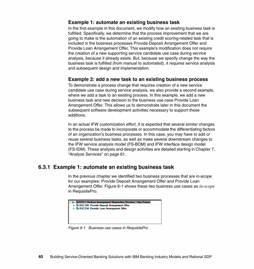
Example 1: automate an existing business taskIn the first example in this document, we modify how an existing business task is fulfilled. Specifically, we determine that the process improvement that we are going to make is the automation of an existing credit scoring-related task that is included in the business processes Provide Deposit Arrangement Offer and Provide Loan Arrangement Offer. This example's modification does not require the creation of a new supporting service candidate use case during service analysis, because it already exists. But, because we specify change the way the business task is fulfilled (from manual to automated), it requires service analysis and subsequent design and implementation.
Example 2: add a new task to an existing business processTo demonstrate a process change that requires creation of a new service candidate use case during service analysis, we also provide a second example, where we add a task to an existing process. In this example, we add a new business task and new decision to the business use case Provide Loan Arrangement Offer. This allows us to demonstrate later in this document the subsequent software development activities necessary to support these additions.
In an actual IFW customization effort, it is expected that several similar changes to the process be made to incorporate or accommodate the differentiating factors of an organization’s business processes. In this case, you may have to add or reuse several business tasks, as well as make several downstream changes to the IFW service analysis model (FS-BOM) and IFW interface design model (FS-IDM). These analysis and design activities are detailed starting in Chapter 7, “Analyze Services” on page 61.
6.3.1 Example 1: automate an existing business task
In the previous chapter we identified two business processes that are in-scope for our examples: Provide Deposit Arrangement Offer and Provide Loan Arrangement Offer. Figure 6-1 shows these two business use cases as in-scope in RequisitePro.
Figure 6-1 Business use cases in RequisitePro
40 Building Service-Oriented Banking Solutions with IBM Banking Industry Models and Rational SDP
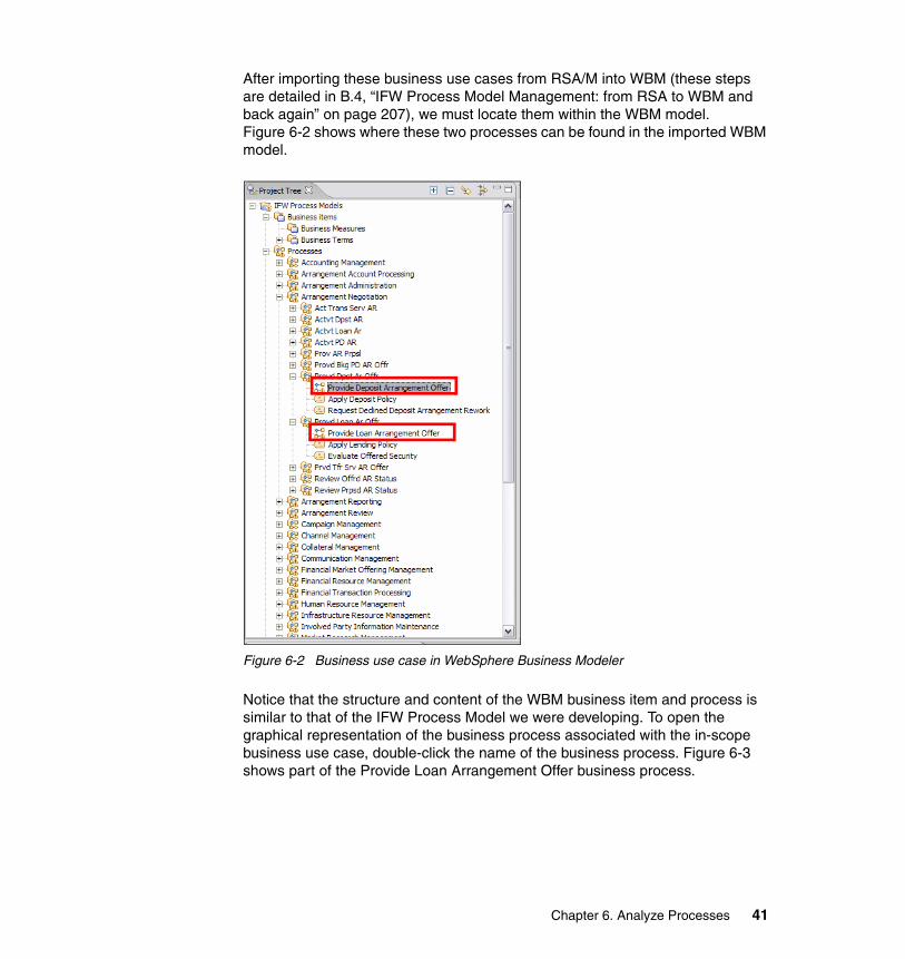
After importing these business use cases from RSA/M into WBM (these steps are detailed in B.4, “IFW Process Model Management: from RSA to WBM and back again” on page 207), we must locate them within the WBM model. Figure 6-2 shows where these two processes can be found in the imported WBM model.
Figure 6-2 Business use case in WebSphere Business Modeler
Notice that the structure and content of the WBM business item and process is similar to that of the IFW Process Model we were developing. To open the graphical representation of the business process associated with the in-scope business use case, double-click the name of the business process. Figure 6-3 shows part of the Provide Loan Arrangement Offer business process.
Chapter 6. Analyze Processes 41
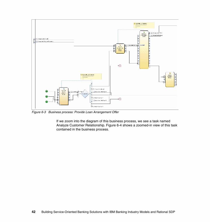
Figure 6-3 Business process: Provide Loan Arrangement Offer
If we zoom into the diagram of this business process, we see a task named Analyze Customer Relationship. Figure 6-4 shows a zoomed-in view of this task contained in the business process.
42 Building Service-Oriented Banking Solutions with IBM Banking Industry Models and Rational SDP
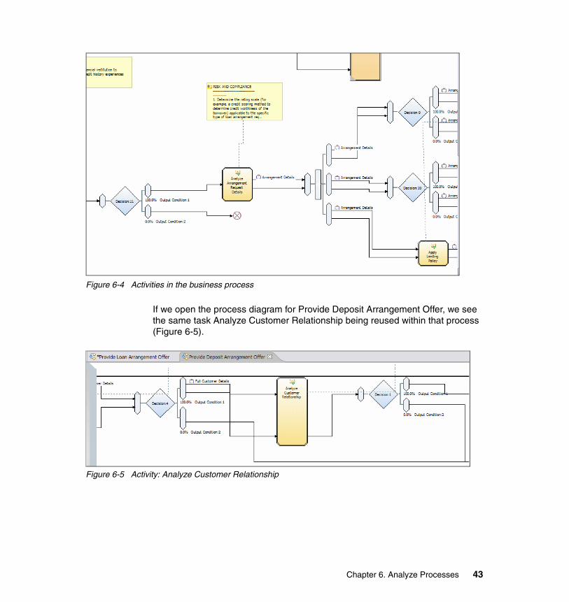
Figure 6-4 Activities in the business process
If we open the process diagram for Provide Deposit Arrangement Offer, we see the same task Analyze Customer Relationship being reused within that process (Figure 6-5).
Figure 6-5 Activity: Analyze Customer Relationship
Chapter 6. Analyze Processes 43
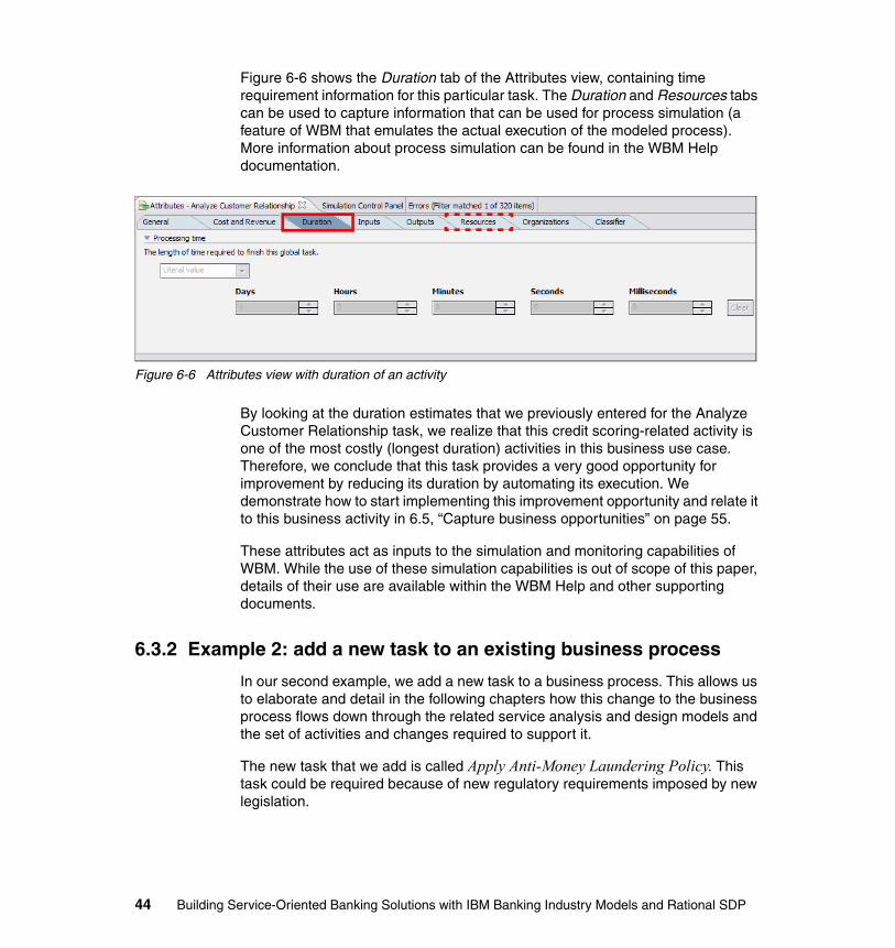
Figure 6-6 shows the Duration tab of the Attributes view, containing time requirement information for this particular task. The Duration and Resources tabs can be used to capture information that can be used for process simulation (a feature of WBM that emulates the actual execution of the modeled process). More information about process simulation can be found in the WBM Help documentation.
Figure 6-6 Attributes view with duration of an activity
By looking at the duration estimates that we previously entered for the Analyze Customer Relationship task, we realize that this credit scoring-related activity is one of the most costly (longest duration) activities in this business use case. Therefore, we conclude that this task provides a very good opportunity for improvement by reducing its duration by automating its execution. We demonstrate how to start implementing this improvement opportunity and relate it to this business activity in 6.5, “Capture business opportunities” on page 55.
These attributes act as inputs to the simulation and monitoring capabilities of WBM. While the use of these simulation capabilities is out of scope of this paper, details of their use are available within the WBM Help and other supporting documents.
6.3.2 Example 2: add a new task to an existing business process
In our second example, we add a new task to a business process. This allows us to elaborate and detail in the following chapters how this change to the business process flows down through the related service analysis and design models and the set of activities and changes required to support it.
The new task that we add is called Apply Anti-Money Laundering Policy. This task could be required because of new regulatory requirements imposed by new legislation.
44 Building Service-Oriented Banking Solutions with IBM Banking Industry Models and Rational SDP

First, ensure that you are working in the WBM advanced modeling mode. Select Modeling → Mode → Advanced (Figure 6-7).
Figure 6-7 Selecting advanced modeling mode
By analyzing the Provide Loan Arrangement Offer process we determine that the new Apply Anti-Money Laundering Policy task has to be added in the workflow control logic immediately prior to the Analyze Arrangement Request Details task.
Note: You can quickly locate any process model element within a process opened in the Process Diagram Editor by clicking Structure in the Outline view and then navigating the structure tree to the desired model element.
In this example, locate the Analyze Arrangement Request Details task by clicking Structure, expanding the Process node, and scrolling down to and double-clicking Analyze Arrangement Request Details (Figure 6-8).
Tip: IFW provides standard naming conventions that should be followed to enhance understanding and re-usability. The naming conventions are articulated in IFW's set of standard nouns and verbs.
Note: A new regulation like this could force the addition of a new business goal or objective, for example, Comply with new Anti-Money Laundering regulations, which could be captured in RequisitePro and then traced to business functions or to a business use case impacted by it and so forth, just like we did in the previous chapter. However, because this example is included only to illustrate the impact of adding a new business task, we do not detail these steps again.
Chapter 6. Analyze Processes 45
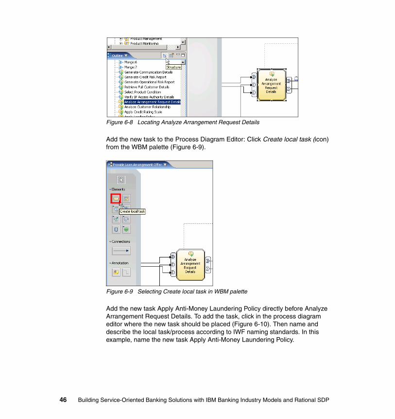
Figure 6-8 Locating Analyze Arrangement Request Details
Add the new task to the Process Diagram Editor: Click Create local task (icon) from the WBM palette (Figure 6-9).
Figure 6-9 Selecting Create local task in WBM palette
Add the new task Apply Anti-Money Laundering Policy directly before Analyze Arrangement Request Details. To add the task, click in the process diagram editor where the new task should be placed (Figure 6-10). Then name and describe the local task/process according to IWF naming standards. In this example, name the new task Apply Anti-Money Laundering Policy.
46 Building Service-Oriented Banking Solutions with IBM Banking Industry Models and Rational SDP
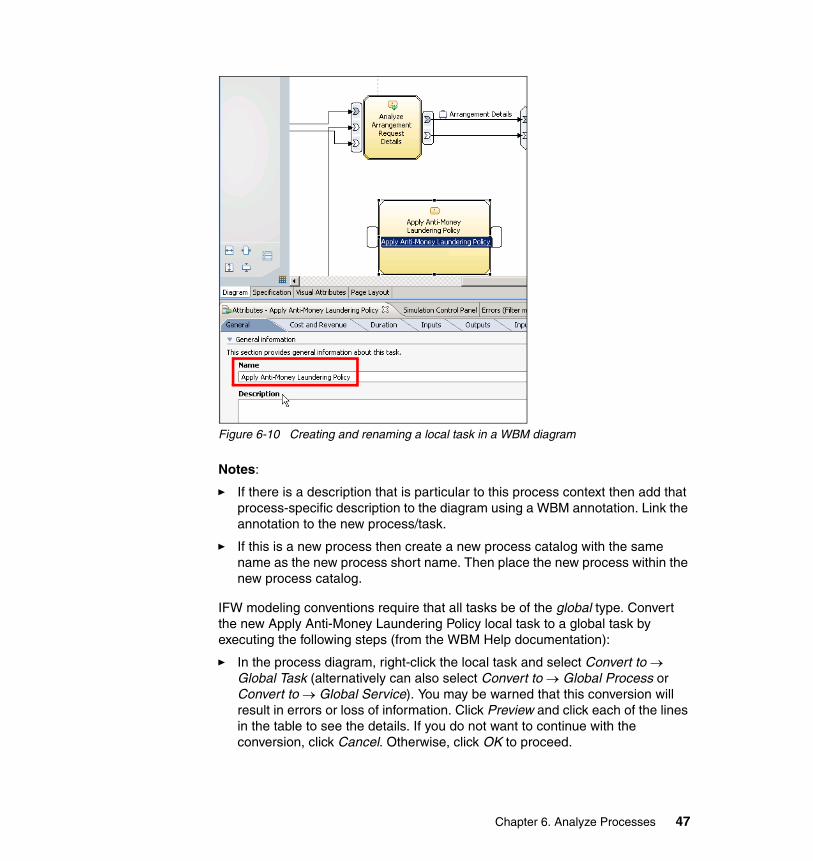
Figure 6-10 Creating and renaming a local task in a WBM diagram
Notes:
� If there is a description that is particular to this process context then add that process-specific description to the diagram using a WBM annotation. Link the annotation to the new process/task.
� If this is a new process then create a new process catalog with the same name as the new process short name. Then place the new process within the new process catalog.
IFW modeling conventions require that all tasks be of the global type. Convert the new Apply Anti-Money Laundering Policy local task to a global task by executing the following steps (from the WBM Help documentation):
� In the process diagram, right-click the local task and select Convert to → Global Task (alternatively can also select Convert to → Global Process or Convert to → Global Service). You may be warned that this conversion will result in errors or loss of information. Click Preview and click each of the lines in the table to see the details. If you do not want to continue with the conversion, click Cancel. Otherwise, click OK to proceed.
Chapter 6. Analyze Processes 47
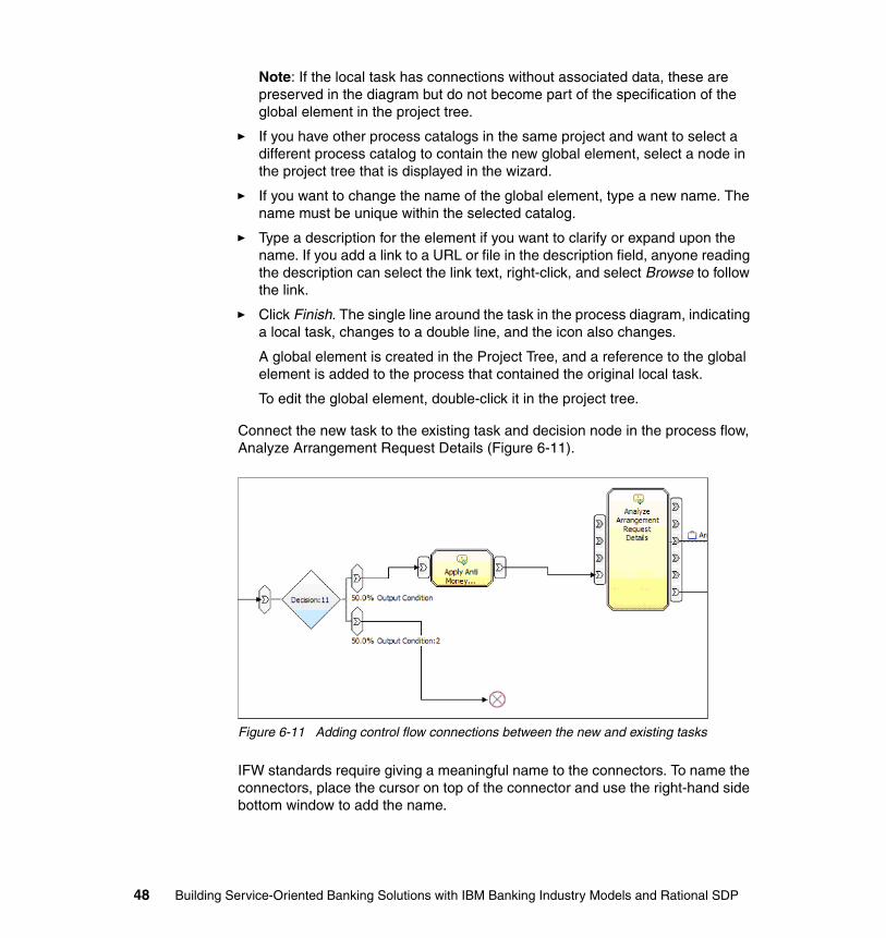
Note: If the local task has connections without associated data, these are preserved in the diagram but do not become part of the specification of the global element in the project tree.
� If you have other process catalogs in the same project and want to select a different process catalog to contain the new global element, select a node in the project tree that is displayed in the wizard.
� If you want to change the name of the global element, type a new name. The name must be unique within the selected catalog.
� Type a description for the element if you want to clarify or expand upon the name. If you add a link to a URL or file in the description field, anyone reading the description can select the link text, right-click, and select Browse to follow the link.
� Click Finish. The single line around the task in the process diagram, indicating a local task, changes to a double line, and the icon also changes.
A global element is created in the Project Tree, and a reference to the global element is added to the process that contained the original local task.
To edit the global element, double-click it in the project tree.
Connect the new task to the existing task and decision node in the process flow, Analyze Arrangement Request Details (Figure 6-11).
Figure 6-11 Adding control flow connections between the new and existing tasks
IFW standards require giving a meaningful name to the connectors. To name the connectors, place the cursor on top of the connector and use the right-hand side bottom window to add the name.
48 Building Service-Oriented Banking Solutions with IBM Banking Industry Models and Rational SDP
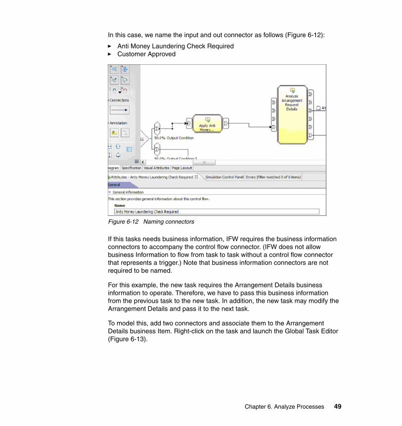
In this case, we name the input and out connector as follows (Figure 6-12):
� Anti Money Laundering Check Required� Customer Approved
Figure 6-12 Naming connectors
If this tasks needs business information, IFW requires the business information connectors to accompany the control flow connector. (IFW does not allow business Information to flow from task to task without a control flow connector that represents a trigger.) Note that business information connectors are not required to be named.
For this example, the new task requires the Arrangement Details business information to operate. Therefore, we have to pass this business information from the previous task to the new task. In addition, the new task may modify the Arrangement Details and pass it to the next task.
To model this, add two connectors and associate them to the Arrangement Details business Item. Right-click on the task and launch the Global Task Editor (Figure 6-13).
Chapter 6. Analyze Processes 49
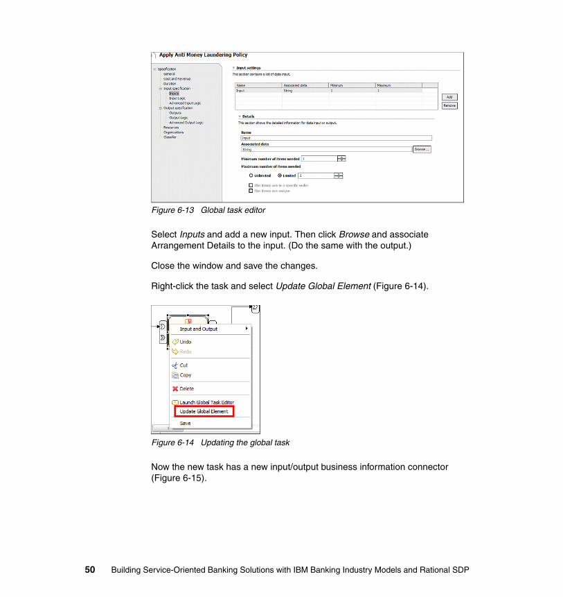
Figure 6-13 Global task editor
Select Inputs and add a new input. Then click Browse and associate Arrangement Details to the input. (Do the same with the output.)
Close the window and save the changes.
Right-click the task and select Update Global Element (Figure 6-14).
Figure 6-14 Updating the global task
Now the new task has a new input/output business information connector (Figure 6-15).
50 Building Service-Oriented Banking Solutions with IBM Banking Industry Models and Rational SDP
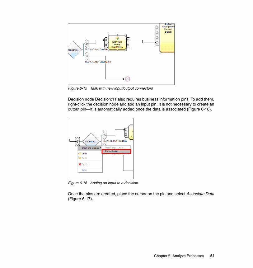
Figure 6-15 Task with new input/output connectors
Decision node Decision:11 also requires business information pins. To add them, right-click the decision node and add an input pin. It is not necessary to create an output pin—it is automatically added once the data is associated (Figure 6-16).
Figure 6-16 Adding an input to a decision
Once the pins are created, place the cursor on the pin and select Associate Data (Figure 6-17).
Chapter 6. Analyze Processes 51
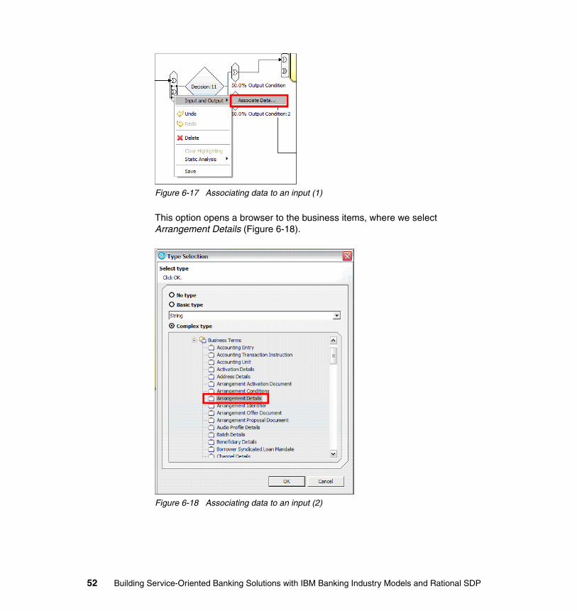
Figure 6-17 Associating data to an input (1)
This option opens a browser to the business items, where we select Arrangement Details (Figure 6-18).
Figure 6-18 Associating data to an input (2)
52 Building Service-Oriented Banking Solutions with IBM Banking Industry Models and Rational SDP
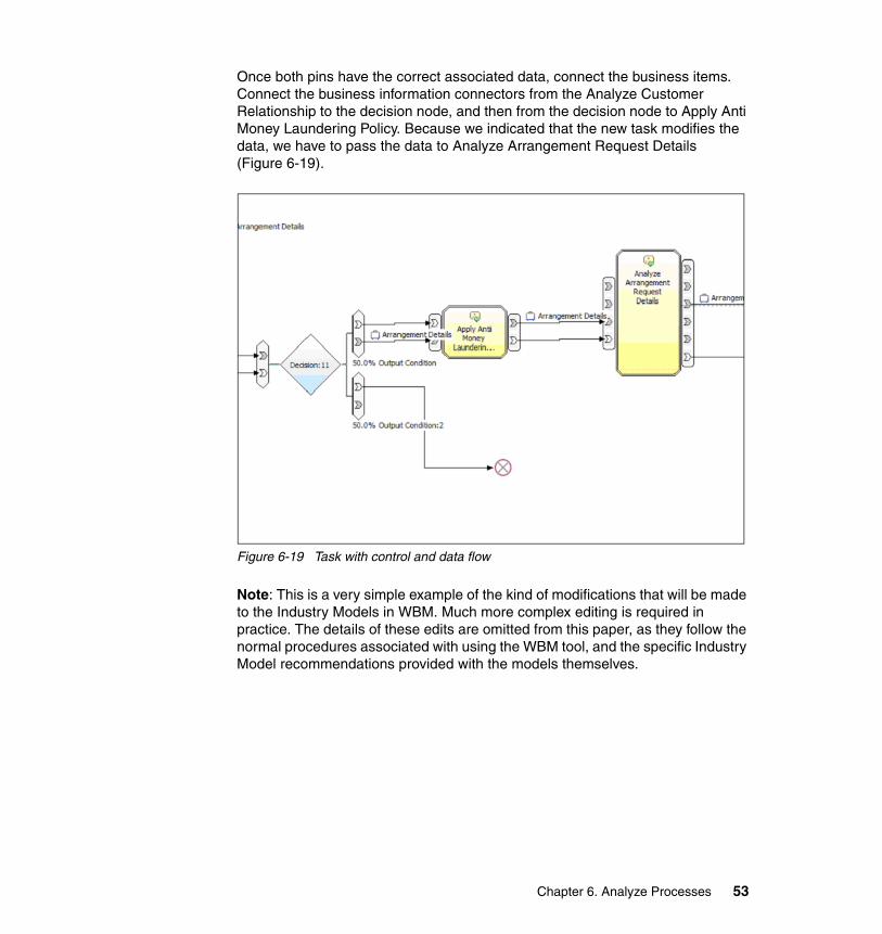
Once both pins have the correct associated data, connect the business items. Connect the business information connectors from the Analyze Customer Relationship to the decision node, and then from the decision node to Apply Anti Money Laundering Policy. Because we indicated that the new task modifies the data, we have to pass the data to Analyze Arrangement Request Details (Figure 6-19).
Figure 6-19 Task with control and data flow
Note: This is a very simple example of the kind of modifications that will be made to the Industry Models in WBM. Much more complex editing is required in practice. The details of these edits are omitted from this paper, as they follow the normal procedures associated with using the WBM tool, and the specific Industry Model recommendations provided with the models themselves.
Chapter 6. Analyze Processes 53

6.4 Refine textual business requirements
Every business process may have an associated business use case (BUC) specification in RequisitePro. A BUC specification describes textually—usually in greater detail—and compliments the graphical business process description like that captured in WBM in the previous steps. In this case, we can create a BUC specification in RequisitePro that corresponds to the graphical representation of the business process.
The IFW RequisitePro project template provides a predefined BUC requirements document template that can be used to consistently capture and specify business use cases. This BUC template defines sections for textual information that typically should be captured for each business use case. This is a suggested format, which your organization can customize to meet its specific needs.
The sections contained in the standard IFW business use case template are shown in Table 6-1.
Table 6-1 IFW business use case template
Note: At the time of writing this document, IFW did not work with WBM V6.0.2. WBM V6.02 can be used with RequisitePro to link requirements directly to WBM model elements. Because this document is operating with Version 6.0.1 of WBM, which does not integrate with RequisitePro, we perform the mapping of business processes to requirements in RequisitePro, utilizing its integration with RSA/M.
Name Description
Business Use Case Name
A unique name that specifically defines this activity, process, or nested process, using an IFW Verb operating on a business object.
Summary Activity Definition
A concise but accurate business definition, usually of the form The business purpose of this Activity is to…
Detailed Activity Description
A very detailed and unambiguous description of what happens within the activity. This definition should make it clear what is in scope and what is out of scope for this activity, and what is achieved for the business by this activity.
The definition may take the form: This Activity (String) encompasses the activities necessary for <Organization Name> to… and may include a bulleted list of the specific responsibilities of this activity, or the specific context describing why this activity is necessary to the business, to achieve certain goals, objectives, and functions relevant to this process.
54 Building Service-Oriented Banking Solutions with IBM Banking Industry Models and Rational SDP
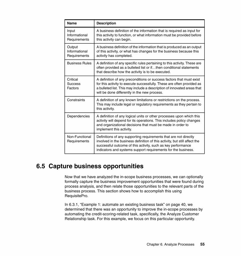
6.5 Capture business opportunities
Now that we have analyzed the in-scope business processes, we can optionally formally capture the business improvement opportunities that were found during process analysis, and then relate those opportunities to the relevant parts of the business process. This section shows how to accomplish this using RequisitePro.
In 6.3.1, “Example 1: automate an existing business task” on page 40, we determined that there was an opportunity to improve the in-scope processes by automating the credit-scoring-related task, specifically, the Analyze Customer Relationship task. For this example, we focus on this particular opportunity.
Input Informational Requirements
A business definition of the information that is required as input for this activity to function, or what information must be provided before this activity can begin.
Output Informational Requirements
A business definition of the information that is produced as an output of this activity, or what has changes for the business because this activity has completed.
Business Rules A definition of any specific rules pertaining to this activity. These are often provided as a bulleted list or if…then conditional statements that describe how the activity is to be executed.
Critical Success Factors
A definition of any preconditions or success factors that must exist for this activity to execute successfully. These are often provided as a bulleted list. This may include a description of innovated areas that will be done differently in the new process.
Constraints A definition of any known limitations or restrictions on the process. This may include legal or regulatory requirements as they pertain to this activity.
Dependencies A definition of any logical units or other processes upon which this activity will depend for its operations. This includes policy changes and organizational decisions that must be made in order to implement this activity.
Non-Functional Requirements
Definitions of any supporting requirements that are not directly involved in the business definition of this activity, but still affect the successful outcome of this activity, such as key performance indicators and systems support requirements for the business.
Name Description
Chapter 6. Analyze Processes 55

First, we must formally capture the new business improvement opportunity by creating a new business opportunity requirement (OPP) in RequisitePro. To accomplish this we open the existing All Business Opps view and enter a new record named Automate Credit Scoring.
Figure 6-20 shows the location of the All Business Opps view, and Figure 6-21 shows that the new record that has been created.
Figure 6-20 All Business Opps view in RequisitePro
Figure 6-21 New record: Automate Credit Scoring in RequisitePro
After creating the business opportunity record it can be mapped to a business opportunity to a business use case. It should be noted that for the approach described in this document, business use cases always exist for full business processes, and may optionally exist for business tasks within those processes. Figure 6-22 shows how we can create this mapping by creating a trace relationship within the traceability matrix named 4 - Business Use Cases to Business Opps.
56 Building Service-Oriented Banking Solutions with IBM Banking Industry Models and Rational SDP
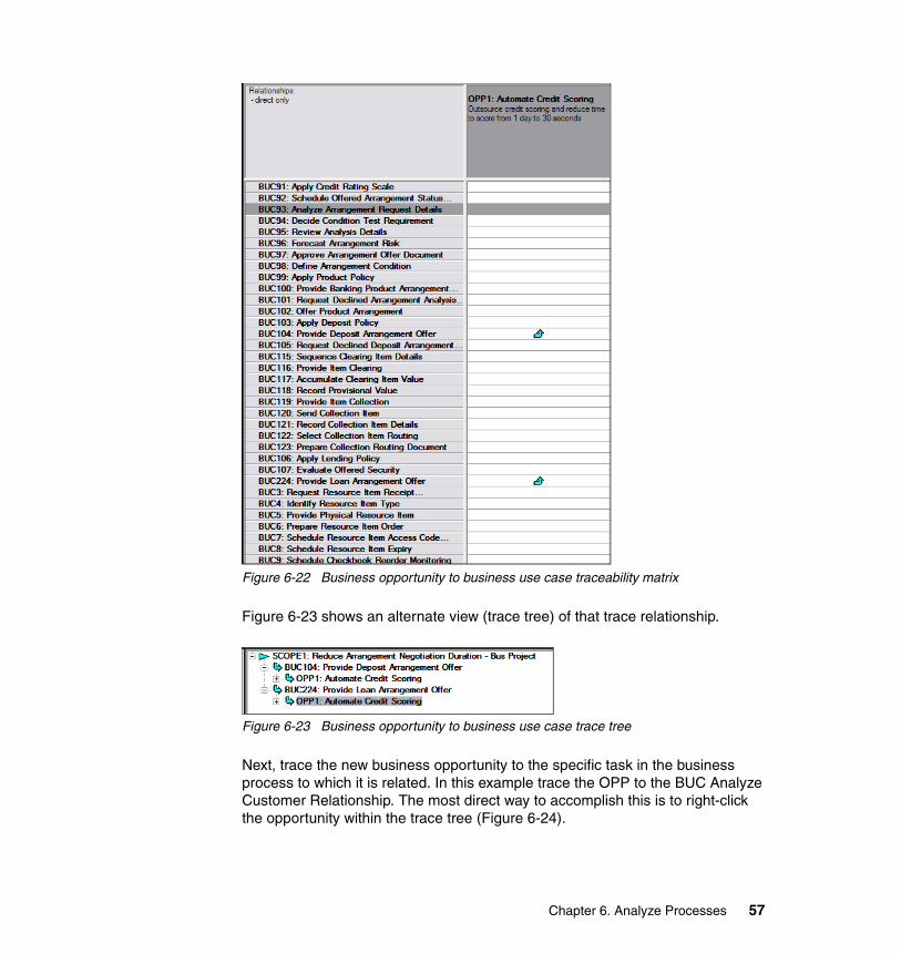
Figure 6-22 Business opportunity to business use case traceability matrix
Figure 6-23 shows an alternate view (trace tree) of that trace relationship.
Figure 6-23 Business opportunity to business use case trace tree
Next, trace the new business opportunity to the specific task in the business process to which it is related. In this example trace the OPP to the BUC Analyze Customer Relationship. The most direct way to accomplish this is to right-click the opportunity within the trace tree (Figure 6-24).
Chapter 6. Analyze Processes 57
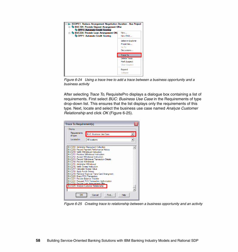
Figure 6-24 Using a trace tree to add a trace between a business opportunity and a business activity
After selecting Trace To, RequisitePro displays a dialogue box containing a list of requirements. First select BUC: Business Use Case in the Requirements of type drop-down list. This ensures that the list displays only the requirements of this type. Next, locate and select the business use case named Analyze Customer Relationship and click OK (Figure 6-25).
Figure 6-25 Creating trace to relationship between a business opportunity and an activity
58 Building Service-Oriented Banking Solutions with IBM Banking Industry Models and Rational SDP
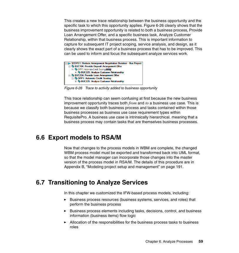
This creates a new trace relationship between the business opportunity and the specific task to which this opportunity applies. Figure 6-26 clearly shows that the business improvement opportunity is related to both a business process, Provide Loan Arrangement Offer, and a specific business task, Analyze Customer Relationship, within that business process. This is important information to capture for subsequent IT project scoping, service analysis, and design, as it clearly shows the exact part of a business process that has to be improved. This can be used to inform and focus the subsequent analyze services work.
Figure 6-26 Trace to activity added to business opportunity
This trace relationship can seem confusing at first because the new business improvement opportunity traces both from and to a business use case. This is because we classify both business process and tasks contained within those business processes as business use case requirement types within RequisitePro. A business use case is intrinsically hierarchical. meaning that a business process may contain tasks that are themselves business processes.
6.6 Export models to RSA/M
Now that changes to the process models in WBM are complete, the changed WBM process model must be exported and transformed back into UML format, so that the model manager can incorporate those changes into the master version of the process model in RSA/M. The details of this procedure are in Appendix B, “Modeling project setup and management” on page 191.
6.7 Transitioning to Analyze Services
In this chapter we customized the IFW-based process models, including:
� Business process resources (business systems, services, and roles) that perform the business process
� Business process elements including tasks, decisions, control, and business information (business items) flow logic
� Allocation of the responsibilities for the business process tasks to business roles
Chapter 6. Analyze Processes 59
� Associated business functional and non-functional requirements including business rules
In addition, the business analysis work revealed business improvement opportunities that were captured in RequisitePro, associated (traced) with the analyzed business process, and traced directly to the specific part of the business process associated with the business improvement opportunity. This tracing of business opportunities to associated parts of the analyzed business process enables more precise and focused scoping of subsequent project work starting with service analysis work, as detailed in the next chapter.
Chapter 7, “Analyze Services” on page 61, shows in detail how the IFW industry models can be used with Rational Software Architect (RSA) or Software Modeler (RSM) and RequisitePro to Analyze Services.
60 Building Service-Oriented Banking Solutions with IBM Banking Industry Models and Rational SDP
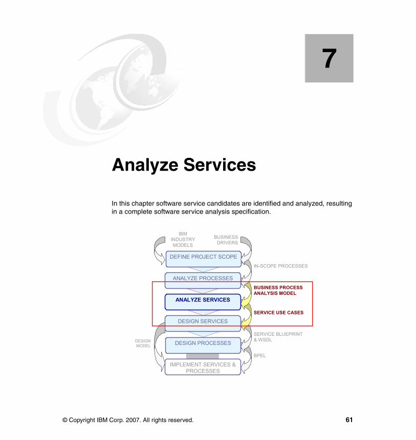
Chapter 7. Analyze Services
In this chapter software service candidates are identified and analyzed, resulting in a complete software service analysis specification.
7
DEFINE PROJECT SCOPE
ANALYZE SERVICES
DESIGN SERVICES
DESIGN PROCESSES
IMPLEMENT SERVICES & PROCESSES
ANALYZE PROCESSES
IN-SCOPE PROCESSES
BUSINESS PROCESS ANALYSIS MODEL
SERVICE BLUEPRINT& WSDL
BPEL
SERVICE USE CASES
DESIGNMODEL
IBMINDUSTRYMODELS
BUSINESSDRIVERS
© Copyright IBM Corp. 2007. All rights reserved. 61

7.1 Introduction to Analyze Services1
Analyzing software services with IFW starts by analyzing the business (process) analysis model for highly re-used and automatable business tasks. These business tasks are associated with service candidate use cases that are, in turn, analyzed and modeled to provide a complete service analysis specification that serves as the basis for subsequent service design activities. Key considerations for identifying and assessing re-usable service candidates include commonality/variability based on context of use, frequency of use, and other non-functional requirements.
7.2 Using IBM Rational SDP to Analyze Services
This section details how the IBM IFW Banking Industry models can be used with IBM Rational Software Architect (RSA) or Software Modeler (RSM) and RequisitePro (ReqPro) components of the IBM Rational SDP to:
� Identify software service candidates.� Create associated text-based requirements and IT project scope.� Analyze and model detailed service specifications.
RSA/M and RequisitePro are integrated analysis, design, and development components in the IBM Rational SDP. This section provides a brief introduction and overview of these tools that are used to Analyze Services:
� IBM Rational Software Architect (RSA): An advanced Unified Modeling Language (UML) 2.0 model-driven development and static analysis modeling and development tool for software architects and model-driven developers creating service-oriented architecture (SOA), J2EE, and portal applications. This integrated analysis, design, and development tool supports understanding, designing, managing, and evolving enterprise solutions and services. Part of the flexible family of business-driven development products that constitute the SDP, which is built on the open Eclipse integration platform, Rational Software Architect offers extended support for the Object Management Group's (OMG) industry standard Unified Modeling Language (UML). RSA's many powerful visual modeling and editing features are designed to improve productivity, enhance architectural control, and ease the design-to-code experience for Java/Java 2, Enterprise Edition. RSA includes and provides additional capabilities to those provided in both RSM and
1 Notes: 1) Additional methodological guidance/motivation is available in the IM&A Model Customization Roadmap. 2) Detailed IM&A modeling guidelines for WBM and RSx are available in the IM&A Process and Service Models Metamodel Guide and other related publications. These publications are available to licensees of the IBM Industry Models. Send an e-mail to [email protected] to ask for access.
62 Building Service-Oriented Banking Solutions with IBM Banking Industry Models and Rational SDP
Rational Application Developer (RAD). In the roadmap provided in this paper, the better of the two products would be used for implementing services.
� IBM Rational Software Modeler (RSM): A UML 2.0-based visual modeling and design tool for architects, analysts, and designers who have to ensure that their specifications, architectures, and designs are clearly defined and communicated. RSM is also part of the flexible family of business-driven development products that constitute the SDP, which is built on the open Eclipse integration platform. RSM provides a sub-set of the capabilities of RSA (it does not, for example, include the RAD components contained in RSA) and, as such, can be used by analysts and designers who do not need the additional (primarily RAD-based) capabilities provided by RSA.
� Rational RequisitePro (ReqPro): Complementing the RSA/M architecture management tools, RequisitePro is a powerful, easy-to-use, and integrated product for requirements and use case management that promotes better communication, enhances teamwork, and reduces project risk. We used RequisitePro extensively in the previous define project scope activity.
Note: Business tasks in WebSphere Business Modeler are represented in RSA/M as UML2 activities. Both are represented as Business Use Case requirement types within the IFW RequisitePro project template.
As we have seen in previous chapters, enterprise-level software projects need traceability throughout, and integration across, the life cycle. A key aspect of the approach detailed in this paper is integrated requirements management. When requirements change, analysts, architects, and designers using RSA/M have to know what part of the architecture is affected.
Requirements stored and managed in RequisitePro can be accessed and, as we have seen, associated to corresponding RSA/M modeling elements and synchronized with user-selectable rules. We utilize this integration heavily throughout this paper.
Projects like those described in this paper also require management of changes to the models and other life cycle artifacts. RSA/M and RequisitePro as integrated parts of the IBM Rational SDP are also integrated with other SDP tooling supporting other parts of the SOA life cycle including IBM Rational ClearCase and ClearQuest, IBM robust configuration and change management product families. Governance and management of the industry models is detailed in another, soon to be published, paper (contact [email protected] for the latest information regarding the status of this paper).
Chapter 7. Analyze Services 63
7.3 Analyze business processes for service candidates
The IFW process model is delivered with business tasks (activities) that have already been deemed good service candidates. These business activities are mapped to identically named Business Object Model (BOM) service candidate use cases. However, if a new business activity has been added to the process model then:
� It must be used to create an associated and synchronized RequisitePro BUC requirement.
� A new, associated service candidate use case has to be added to the BOM and mapped to the business activity.
Continuing our example 1 from the last chapter, we decided to automate the activity named Analyze Customer Relationship. In example 1 do not add any new business activities. However, we should still determine whether any of the changes we made to the business activity affect the related service candidate use case. Additionally, the business activity has to be analyzed to determine its internal workings. This analysis is captured using an activity diagram.
7.3.1 Confirm existence of existing service candidate: example 1
First, locate the business activities within RSA/M that have been changed during process analysis2. Figure 7-1 shows the location of the Analyze Customer Relationship business activity, contained in the RSA/M model.
2 Changes to the process model may be captured, for example, automatically by the configuration management tool used to manage the process model, or a manually generated and maintained list.
64 Building Service-Oriented Banking Solutions with IBM Banking Industry Models and Rational SDP
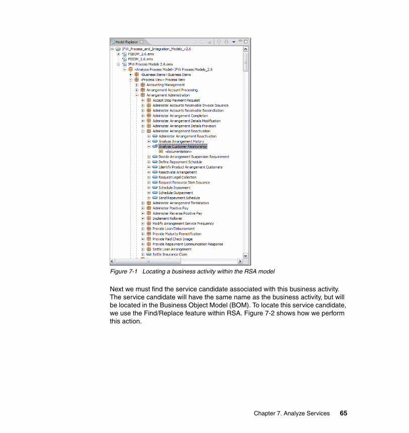
Figure 7-1 Locating a business activity within the RSA model
Next we must find the service candidate associated with this business activity. The service candidate will have the same name as the business activity, but will be located in the Business Object Model (BOM). To locate this service candidate, we use the Find/Replace feature within RSA. Figure 7-2 shows how we perform this action.
Chapter 7. Analyze Services 65
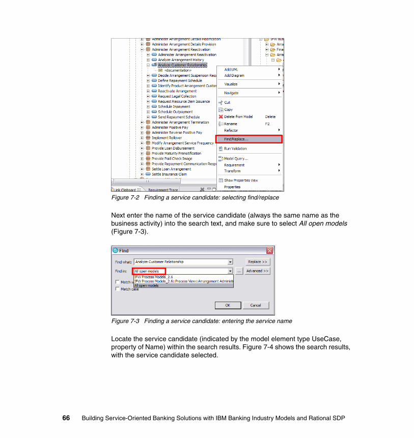
Figure 7-2 Finding a service candidate: selecting find/replace
Next enter the name of the service candidate (always the same name as the business activity) into the search text, and make sure to select All open models (Figure 7-3).
Figure 7-3 Finding a service candidate: entering the service name
Locate the service candidate (indicated by the model element type UseCase, property of Name) within the search results. Figure 7-4 shows the search results, with the service candidate selected.
66 Building Service-Oriented Banking Solutions with IBM Banking Industry Models and Rational SDP
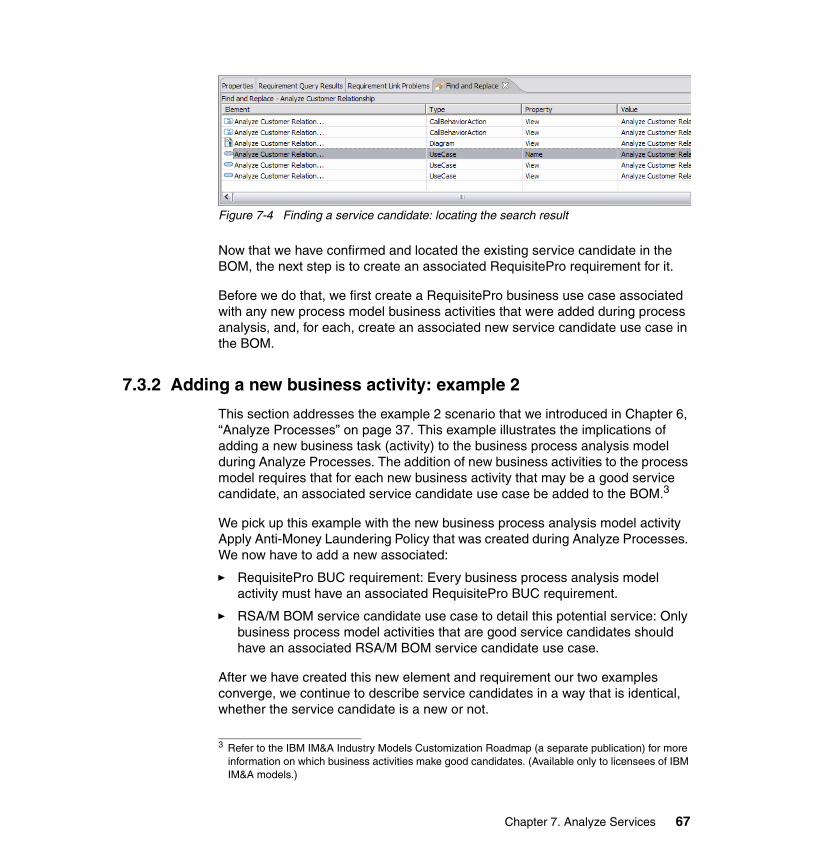
Figure 7-4 Finding a service candidate: locating the search result
Now that we have confirmed and located the existing service candidate in the BOM, the next step is to create an associated RequisitePro requirement for it.
Before we do that, we first create a RequisitePro business use case associated with any new process model business activities that were added during process analysis, and, for each, create an associated new service candidate use case in the BOM.
7.3.2 Adding a new business activity: example 2
This section addresses the example 2 scenario that we introduced in Chapter 6, “Analyze Processes” on page 37. This example illustrates the implications of adding a new business task (activity) to the business process analysis model during Analyze Processes. The addition of new business activities to the process model requires that for each new business activity that may be a good service candidate, an associated service candidate use case be added to the BOM.3
We pick up this example with the new business process analysis model activity Apply Anti-Money Laundering Policy that was created during Analyze Processes. We now have to add a new associated:
� RequisitePro BUC requirement: Every business process analysis model activity must have an associated RequisitePro BUC requirement.
� RSA/M BOM service candidate use case to detail this potential service: Only business process model activities that are good service candidates should have an associated RSA/M BOM service candidate use case.
After we have created this new element and requirement our two examples converge, we continue to describe service candidates in a way that is identical, whether the service candidate is a new or not.
3 Refer to the IBM IM&A Industry Models Customization Roadmap (a separate publication) for more information on which business activities make good candidates. (Available only to licensees of IBM IM&A models.)
Chapter 7. Analyze Services 67
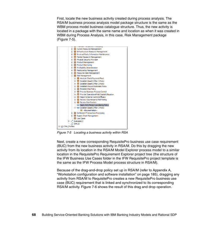
First, locate the new business activity created during process analysis. The RSA/M business process analysis model package structure is the same as the WBM process model business catalogue structure. Thus, the new activity is located in a package with the same name and location as when it was created in WBM during Process Analysis, in this case, Risk Management package (Figure 7-5).
Figure 7-5 Locating a business activity within RSA
Next, create a new corresponding RequisitePro business use case requirement (BUC) from the new business activity in RSA/M. Do this by dragging the new activity from its location in the RSA/M Model Explorer process model to a similar location in the RequisitePro Requirement Explorer project tree (the structure of the IFW Business Use Cases folder in the IFW RequisitePro project template is the same as the IFW Process Model process structure in RSA/M).
Because of the drag-and-drop policy set up in RSA/M (refer to Appendix A, “Workstation configuration and software installation” on page 185), dragging any activity from RSA/M to RequisitePro creates a new RequisitePro business use case (BUC) requirement that is linked and synchronized to its corresponding RSA/M activity. Figure 7-6 shows the result of this drag and drop operation.
68 Building Service-Oriented Banking Solutions with IBM Banking Industry Models and Rational SDP
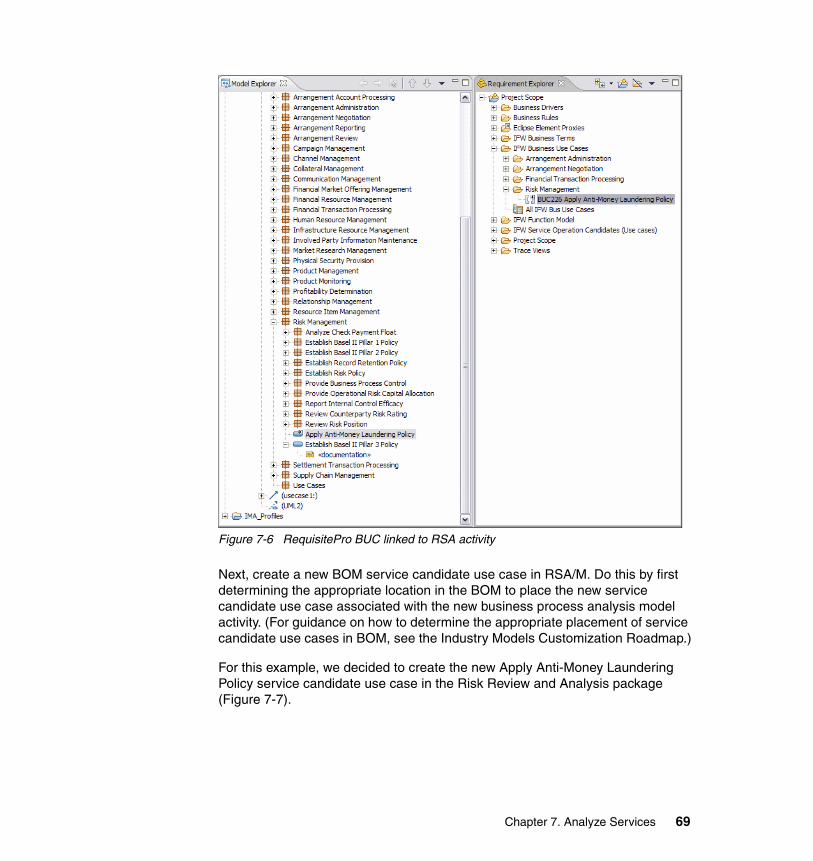
Figure 7-6 RequisitePro BUC linked to RSA activity
Next, create a new BOM service candidate use case in RSA/M. Do this by first determining the appropriate location in the BOM to place the new service candidate use case associated with the new business process analysis model activity. (For guidance on how to determine the appropriate placement of service candidate use cases in BOM, see the Industry Models Customization Roadmap.)
For this example, we decided to create the new Apply Anti-Money Laundering Policy service candidate use case in the Risk Review and Analysis package (Figure 7-7).
Chapter 7. Analyze Services 69
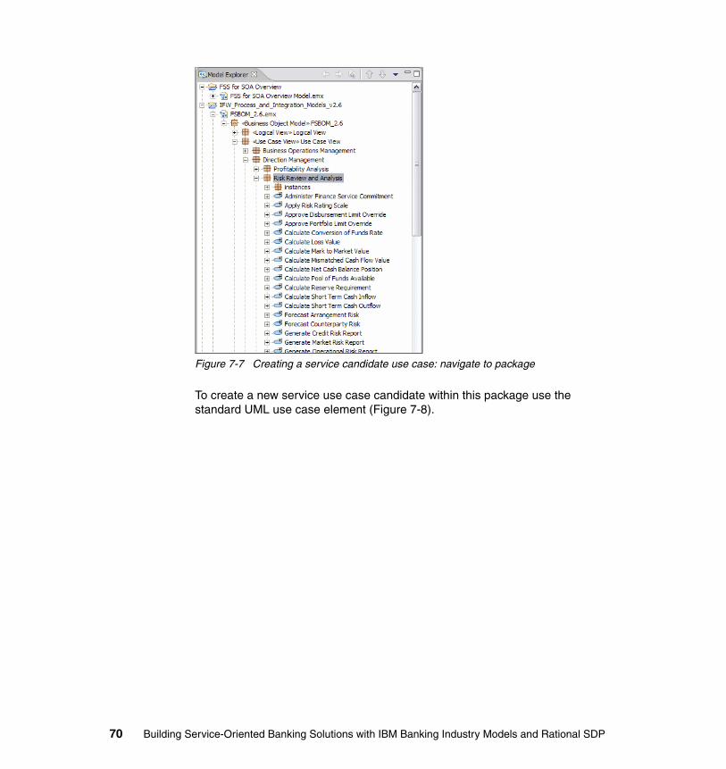
Figure 7-7 Creating a service candidate use case: navigate to package
To create a new service use case candidate within this package use the standard UML use case element (Figure 7-8).
70 Building Service-Oriented Banking Solutions with IBM Banking Industry Models and Rational SDP
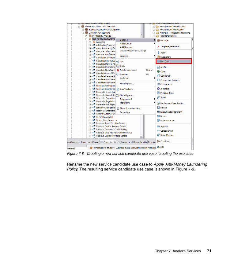
Figure 7-8 Creating a new service candidate use case: creating the use case
Rename the new service candidate use case to Apply Anti-Money Laundering Policy. The resulting service candidate use case is shown in Figure 7-9.
Chapter 7. Analyze Services 71

Figure 7-9 Creating a service candidate use case: changing the name of the use case
7.3.3 Create a service candidate use case in RequisitePro
At this point our two examples (example 1 and example 2) converge. Create a RequisitePro service candidate use case requirement associated with each RSA/M BOM service candidate use case by using the drag-and-drop integration between RSA/M and RequisitePro.
Select the BOM service candidate use case in RSA/M Model Explorer project tree and drag and drop it into the appropriate location in the IFW Service Candidate Use Case folder structure in the RequisitePro Requirement Explorer project tree. The IFW Service Candidate Use Case folder structure in RequisitePro has to be structured and maintained to be the same as the IFW BOM Use Case View RSA/M package structure. Figure 7-10 shows the result of dragging a service candidate use case from RSA/M into the appropriate location in the RequisitePro Requirement Explorer.
72 Building Service-Oriented Banking Solutions with IBM Banking Industry Models and Rational SDP
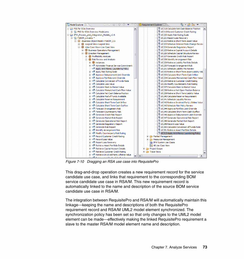
Figure 7-10 Dragging an RSA use case into RequisitePro
This drag-and-drop operation creates a new requirement record for the service candidate use case, and links that requirement to the corresponding BOM service candidate use case in RSA/M. This new requirement record is automatically linked to the name and description of the source BOM service candidate use case in RSA/M.
The integration between RequisitePro and RSA/M will automatically maintain this linkage—keeping the name and descriptions of both the RequisitePro requirement record and RSA/M UML2 model element synchronized. The synchronization policy has been set so that only changes to the UML2 model element can be made—effectively making the linked RequisitePro requirement a slave to the master RSA/M model element name and description.
Chapter 7. Analyze Services 73
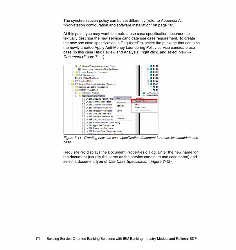
The synchronization policy can be set differently (refer to Appendix A, “Workstation configuration and software installation” on page 185).
At this point, you may want to create a use case specification document to textually describe the new service candidate use case requirement. To create the new use case specification in RequisitePro, select the package that contains the newly created Apply Anti-Money Laundering Policy service candidate use case (in this case Risk Review and Analysis), right click, and select New → Document (Figure 7-11).
Figure 7-11 Creating new use case specification document for a service candidate use case
RequisitePro displays the Document Properties dialog. Enter the new name for the document (usually the same as the service candidate use case name) and select a document type of Use Case Specification (Figure 7-12).
74 Building Service-Oriented Banking Solutions with IBM Banking Industry Models and Rational SDP
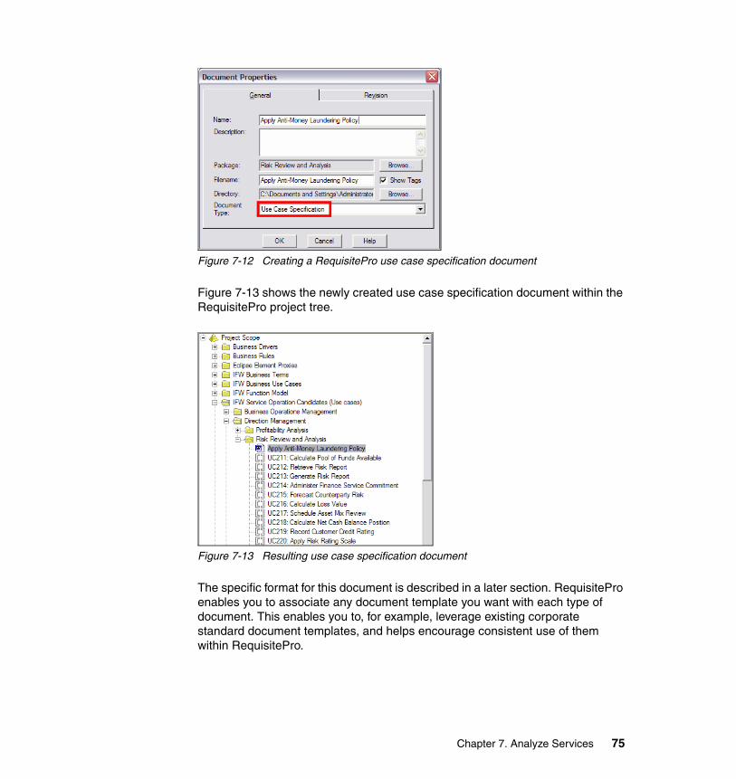
Figure 7-12 Creating a RequisitePro use case specification document
Figure 7-13 shows the newly created use case specification document within the RequisitePro project tree.
Figure 7-13 Resulting use case specification document
The specific format for this document is described in a later section. RequisitePro enables you to associate any document template you want with each type of document. This enables you to, for example, leverage existing corporate standard document templates, and helps encourage consistent use of them within RequisitePro.
Chapter 7. Analyze Services 75
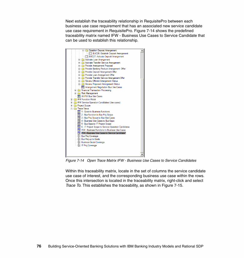
Next establish the traceability relationship in RequisitePro between each business use case requirement that has an associated new service candidate use case requirement in RequisitePro. Figure 7-14 shows the predefined traceability matrix named IFW - Business Use Cases to Service Candidate that can be used to establish this relationship.
Figure 7-14 Open Trace Matrix IFW - Business Use Cases to Service Candidates
Within this traceability matrix, locate in the set of columns the service candidate use case of interest, and the corresponding business use case within the rows. Once this intersection is located in the traceability matrix, right-click and select Trace To. This establishes the traceability, as shown in Figure 7-15.
76 Building Service-Oriented Banking Solutions with IBM Banking Industry Models and Rational SDP
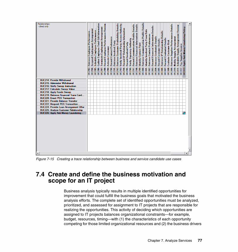
Figure 7-15 Creating a trace relationship between business and service candidate use cases
7.4 Create and define the business motivation and scope for an IT project
Business analysis typically results in multiple identified opportunities for improvement that could fulfill the business goals that motivated the business analysis efforts. The complete set of identified opportunities must be analyzed, prioritized, and assessed for assignment to IT projects that are responsible for realizing the opportunities. This activity of deciding which opportunities are assigned to IT projects balances organizational constraints—for example, budget, resources, timing—with (1) the characteristics of each opportunity competing for those limited organizational resources and (2) the business drivers
Chapter 7. Analyze Services 77

associated with the business opportunity—for example, new regulatory requirements, new market, cost savings, and new revenue. The result of this scoping activity is IT projects that are motivated by and responsible for fulfilling the specific business opportunities through service candidate identification, analysis, design, and other subsequent related activities.
This section shows how to analyze and prioritize the opportunities (OPP) identified and captured during Process Analysis and then (potentially) assign them to an IT project that is responsible for fulfilling the opportunities. This assignment of IT projects to fulfill specific business improvement opportunities is captured through RequisitePro traceability relationships.
7.4.1 Analyze and prioritize business opportunities
The first step in creating a scoped IT project is to review, analyze, and prioritize all business opportunities. Open the All Business Opportunities RequisitePro attribute matrix by double-clicking it in the Project Explorer tree view (Figure 7-16).
Figure 7-16 Opening the All Business Opportunities attribute matrix
Open the Business Opportunities to Business Goals traceability tree by double-clicking it in the Project Explorer tree view (Figure 7-17).
Figure 7-17 Business Opportunities to Business Goals traceability tree with Goal 7 attributes
Assign the priority value of each opportunity (OPP) requirement based on the results of your review and analysis of:
� The opportunity attributes (through the All Business Opportunities attribute matrix)
78 Building Service-Oriented Banking Solutions with IBM Banking Industry Models and Rational SDP
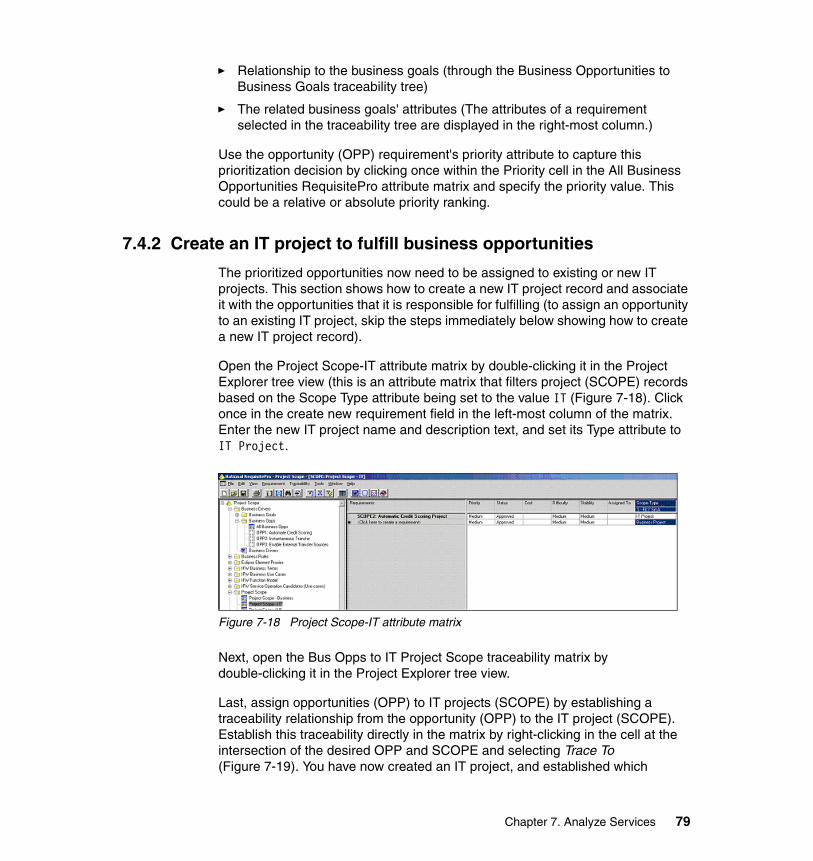
� Relationship to the business goals (through the Business Opportunities to Business Goals traceability tree)
� The related business goals' attributes (The attributes of a requirement selected in the traceability tree are displayed in the right-most column.)
Use the opportunity (OPP) requirement's priority attribute to capture this prioritization decision by clicking once within the Priority cell in the All Business Opportunities RequisitePro attribute matrix and specify the priority value. This could be a relative or absolute priority ranking.
7.4.2 Create an IT project to fulfill business opportunities
The prioritized opportunities now need to be assigned to existing or new IT projects. This section shows how to create a new IT project record and associate it with the opportunities that it is responsible for fulfilling (to assign an opportunity to an existing IT project, skip the steps immediately below showing how to create a new IT project record).
Open the Project Scope-IT attribute matrix by double-clicking it in the Project Explorer tree view (this is an attribute matrix that filters project (SCOPE) records based on the Scope Type attribute being set to the value IT (Figure 7-18). Click once in the create new requirement field in the left-most column of the matrix. Enter the new IT project name and description text, and set its Type attribute to IT Project.
Figure 7-18 Project Scope-IT attribute matrix
Next, open the Bus Opps to IT Project Scope traceability matrix by double-clicking it in the Project Explorer tree view.
Last, assign opportunities (OPP) to IT projects (SCOPE) by establishing a traceability relationship from the opportunity (OPP) to the IT project (SCOPE). Establish this traceability directly in the matrix by right-clicking in the cell at the intersection of the desired OPP and SCOPE and selecting Trace To (Figure 7-19). You have now created an IT project, and established which
Chapter 7. Analyze Services 79
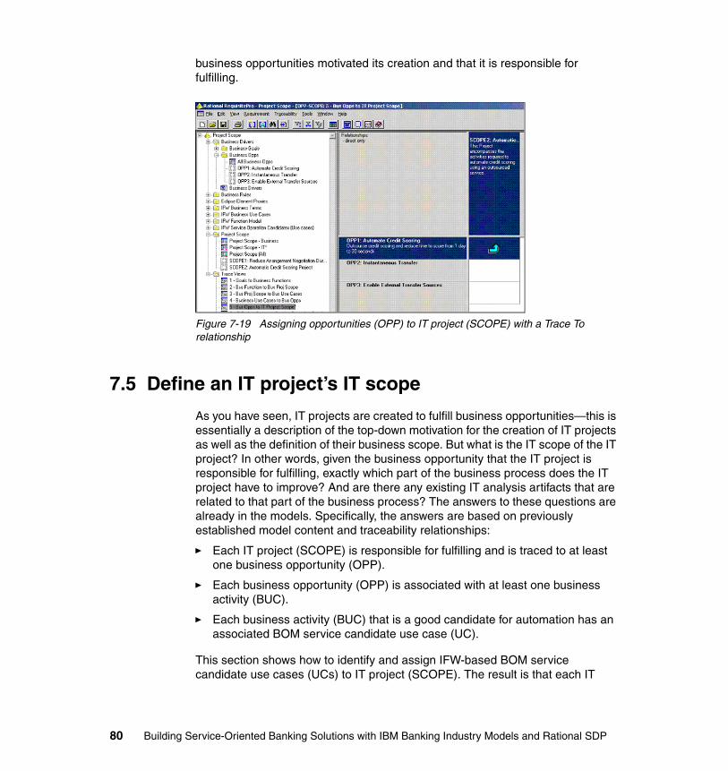
business opportunities motivated its creation and that it is responsible for fulfilling.
Figure 7-19 Assigning opportunities (OPP) to IT project (SCOPE) with a Trace To relationship
7.5 Define an IT project’s IT scope
As you have seen, IT projects are created to fulfill business opportunities—this is essentially a description of the top-down motivation for the creation of IT projects as well as the definition of their business scope. But what is the IT scope of the IT project? In other words, given the business opportunity that the IT project is responsible for fulfilling, exactly which part of the business process does the IT project have to improve? And are there any existing IT analysis artifacts that are related to that part of the business process? The answers to these questions are already in the models. Specifically, the answers are based on previously established model content and traceability relationships:
� Each IT project (SCOPE) is responsible for fulfilling and is traced to at least one business opportunity (OPP).
� Each business opportunity (OPP) is associated with at least one business activity (BUC).
� Each business activity (BUC) that is a good candidate for automation has an associated BOM service candidate use case (UC).
This section shows how to identify and assign IFW-based BOM service candidate use cases (UCs) to IT project (SCOPE). The result is that each IT
80 Building Service-Oriented Banking Solutions with IBM Banking Industry Models and Rational SDP
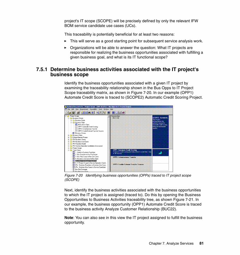
project's IT scope (SCOPE) will be precisely defined by only the relevant IFW BOM service candidate use cases (UCs).
This traceability is potentially beneficial for at least two reasons:
� This will serve as a good starting point for subsequent service analysis work.
� Organizations will be able to answer the question: What IT projects are responsible for realizing the business opportunities associated with fulfilling a given business goal, and what is its IT functional scope?
7.5.1 Determine business activities associated with the IT project's business scope
Identify the business opportunities associated with a given IT project by examining the traceability relationship shown in the Bus Opps to IT Project Scope traceability matrix, as shown in Figure 7-20. In our example (OPP1) Automate Credit Score is traced to (SCOPE2) Automatic Credit Scoring Project.
Figure 7-20 Identifying business opportunities (OPPs) traced to IT project scope (SCOPE)
Next, identify the business activities associated with the business opportunities to which the IT project is assigned (traced to). Do this by opening the Business Opportunities to Business Activities traceability tree, as shown Figure 7-21. In our example, the business opportunity (OPP1) Automate Credit Score is traced to the business activity Analyze Customer Relationship (BUC22).
Note: You can also see in this view the IT project assigned to fulfill the business opportunity.
Chapter 7. Analyze Services 81
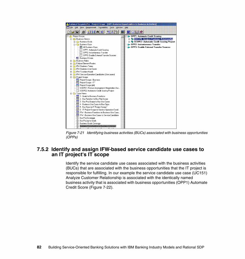
Figure 7-21 Identifying business activities (BUCs) associated with business opportunities (OPPs)
7.5.2 Identify and assign IFW-based service candidate use cases to an IT project's IT scope
Identify the service candidate use cases associated with the business activities (BUCs) that are associated with the business opportunities that the IT project is responsible for fulfilling. In our example the service candidate use case (UC151) Analyze Customer Relationship is associated with the identically named business activity that is associated with business opportunities (OPP1) Automate Credit Score (Figure 7-22).
82 Building Service-Oriented Banking Solutions with IBM Banking Industry Models and Rational SDP
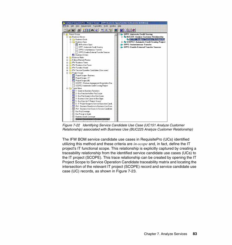
Figure 7-22 Identifying Service Candidate Use Case (UC151 Analyze Customer Relationship) associated with Business Use (BUC225 Analyze Customer Relationship)
The IFW BOM service candidate use cases in RequisitePro (UCs) identified utilizing this method and these criteria are in-scope and, in fact, define the IT project's IT functional scope. This relationship is explicitly captured by creating a traceability relationship from the identified service candidate use cases (UCs) to the IT project (SCOPE). This trace relationship can be created by opening the IT Project Scope to Service Operation Candidate traceability matrix and locating the intersection of the relevant IT project (SCOPE) record and service candidate use case (UC) records, as shown in Figure 7-23.
Chapter 7. Analyze Services 83
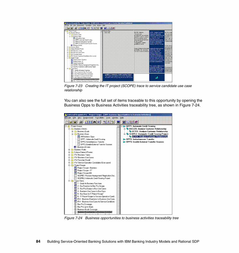
Figure 7-23 Creating the IT project (SCOPE) trace to service candidate use case relationship
You can also see the full set of items traceable to this opportunity by opening the Business Opps to Business Activities traceability tree, as shown in Figure 7-24.
Figure 7-24 Business opportunities to business activities traceability tree
84 Building Service-Oriented Banking Solutions with IBM Banking Industry Models and Rational SDP
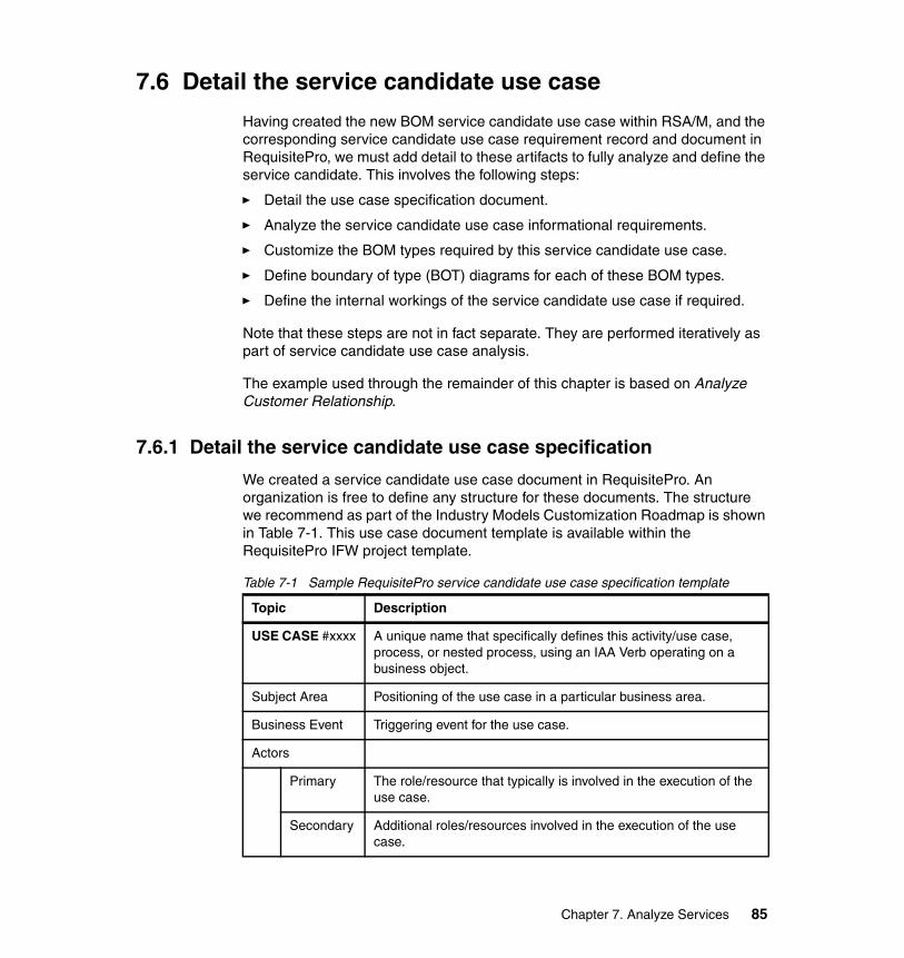
7.6 Detail the service candidate use case
Having created the new BOM service candidate use case within RSA/M, and the corresponding service candidate use case requirement record and document in RequisitePro, we must add detail to these artifacts to fully analyze and define the service candidate. This involves the following steps:
� Detail the use case specification document.
� Analyze the service candidate use case informational requirements.
� Customize the BOM types required by this service candidate use case.
� Define boundary of type (BOT) diagrams for each of these BOM types.
� Define the internal workings of the service candidate use case if required.
Note that these steps are not in fact separate. They are performed iteratively as part of service candidate use case analysis.
The example used through the remainder of this chapter is based on Analyze Customer Relationship.
7.6.1 Detail the service candidate use case specification
We created a service candidate use case document in RequisitePro. An organization is free to define any structure for these documents. The structure we recommend as part of the Industry Models Customization Roadmap is shown in Table 7-1. This use case document template is available within the RequisitePro IFW project template.
Table 7-1 Sample RequisitePro service candidate use case specification template
Topic Description
USE CASE #xxxx A unique name that specifically defines this activity/use case, process, or nested process, using an IAA Verb operating on a business object.
Subject Area Positioning of the use case in a particular business area.
Business Event Triggering event for the use case.
Actors
Primary The role/resource that typically is involved in the execution of the use case.
Secondary Additional roles/resources involved in the execution of the use case.
Chapter 7. Analyze Services 85
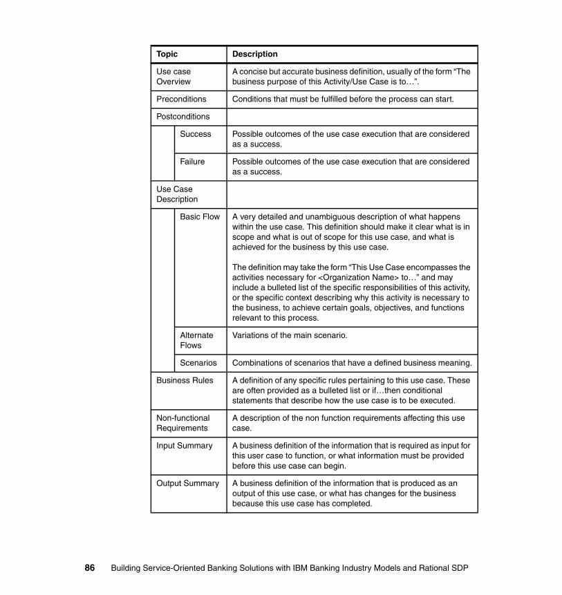
Use case Overview
A concise but accurate business definition, usually of the form “The business purpose of this Activity/Use Case is to…”.
Preconditions Conditions that must be fulfilled before the process can start.
Postconditions
Success Possible outcomes of the use case execution that are considered as a success.
Failure Possible outcomes of the use case execution that are considered as a success.
Use Case Description
Basic Flow A very detailed and unambiguous description of what happens within the use case. This definition should make it clear what is in scope and what is out of scope for this use case, and what is achieved for the business by this use case.
The definition may take the form “This Use Case encompasses the activities necessary for <Organization Name> to…” and may include a bulleted list of the specific responsibilities of this activity, or the specific context describing why this activity is necessary to the business, to achieve certain goals, objectives, and functions relevant to this process.
Alternate Flows
Variations of the main scenario.
Scenarios Combinations of scenarios that have a defined business meaning.
Business Rules A definition of any specific rules pertaining to this use case. These are often provided as a bulleted list or if…then conditional statements that describe how the use case is to be executed.
Non-functional Requirements
A description of the non function requirements affecting this use case.
Input Summary A business definition of the information that is required as input for this user case to function, or what information must be provided before this use case can begin.
Output Summary A business definition of the information that is produced as an output of this use case, or what has changes for the business because this use case has completed.
Topic Description
86 Building Service-Oriented Banking Solutions with IBM Banking Industry Models and Rational SDP
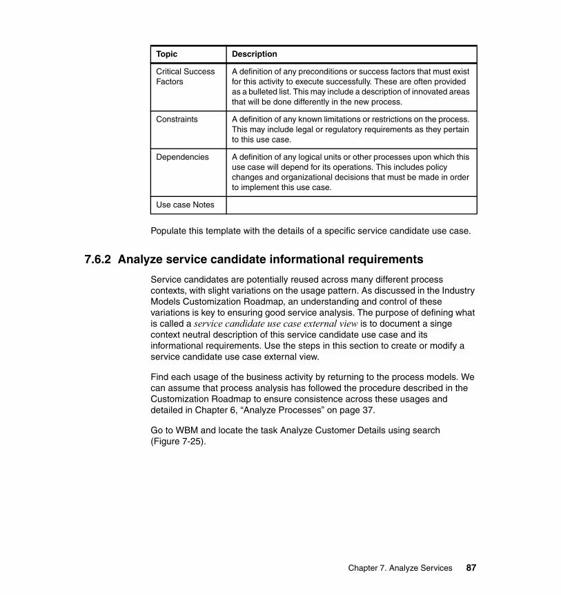
Populate this template with the details of a specific service candidate use case.
7.6.2 Analyze service candidate informational requirements
Service candidates are potentially reused across many different process contexts, with slight variations on the usage pattern. As discussed in the Industry Models Customization Roadmap, an understanding and control of these variations is key to ensuring good service analysis. The purpose of defining what is called a service candidate use case external view is to document a singe context neutral description of this service candidate use case and its informational requirements. Use the steps in this section to create or modify a service candidate use case external view.
Find each usage of the business activity by returning to the process models. We can assume that process analysis has followed the procedure described in the Customization Roadmap to ensure consistence across these usages and detailed in Chapter 6, “Analyze Processes” on page 37.
Go to WBM and locate the task Analyze Customer Details using search (Figure 7-25).
Critical Success Factors
A definition of any preconditions or success factors that must exist for this activity to execute successfully. These are often provided as a bulleted list. This may include a description of innovated areas that will be done differently in the new process.
Constraints A definition of any known limitations or restrictions on the process. This may include legal or regulatory requirements as they pertain to this use case.
Dependencies A definition of any logical units or other processes upon which this use case will depend for its operations. This includes policy changes and organizational decisions that must be made in order to implement this use case.
Use case Notes
Topic Description
Chapter 7. Analyze Services 87
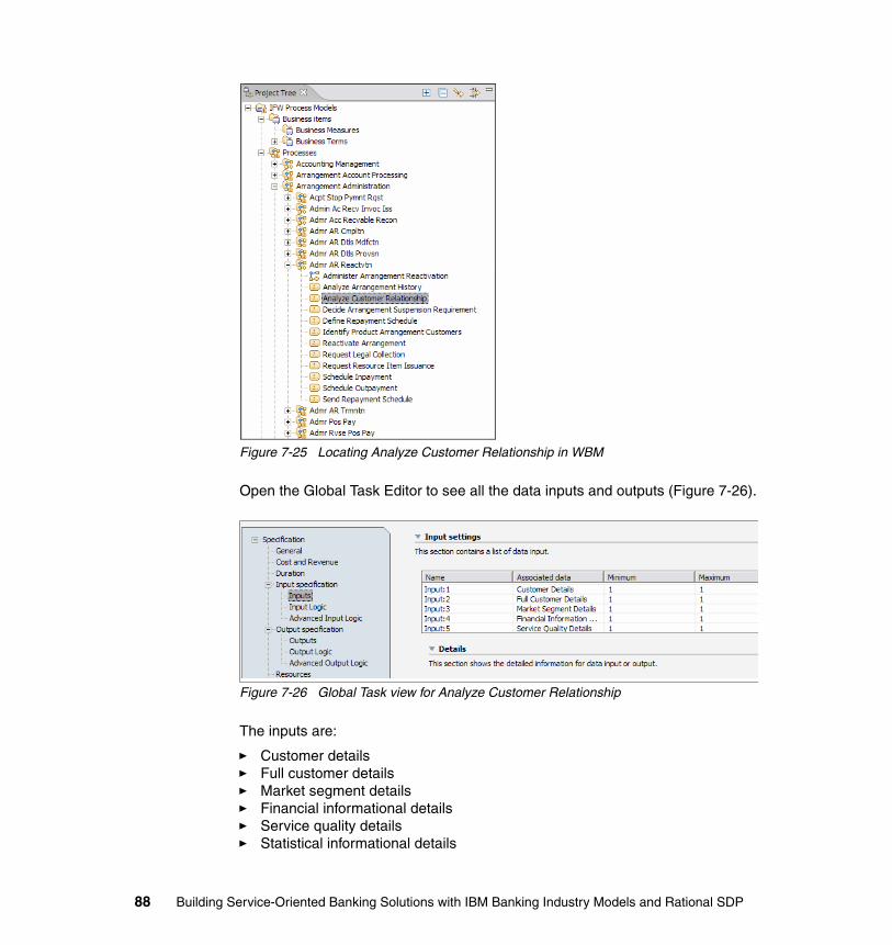
Figure 7-25 Locating Analyze Customer Relationship in WBM
Open the Global Task Editor to see all the data inputs and outputs (Figure 7-26).
Figure 7-26 Global Task view for Analyze Customer Relationship
The inputs are:
� Customer details� Full customer details� Market segment details� Financial informational details� Service quality details� Statistical informational details
88 Building Service-Oriented Banking Solutions with IBM Banking Industry Models and Rational SDP
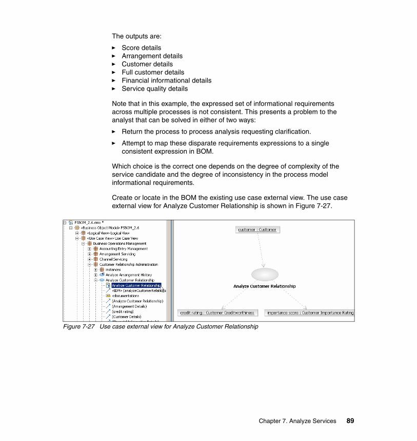
The outputs are:
� Score details� Arrangement details� Customer details� Full customer details� Financial informational details� Service quality details
Note that in this example, the expressed set of informational requirements across multiple processes is not consistent. This presents a problem to the analyst that can be solved in either of two ways:
� Return the process to process analysis requesting clarification.
� Attempt to map these disparate requirements expressions to a single consistent expression in BOM.
Which choice is the correct one depends on the degree of complexity of the service candidate and the degree of inconsistency in the process model informational requirements.
Create or locate in the BOM the existing use case external view. The use case external view for Analyze Customer Relationship is shown in Figure 7-27.
Figure 7-27 Use case external view for Analyze Customer Relationship
Chapter 7. Analyze Services 89
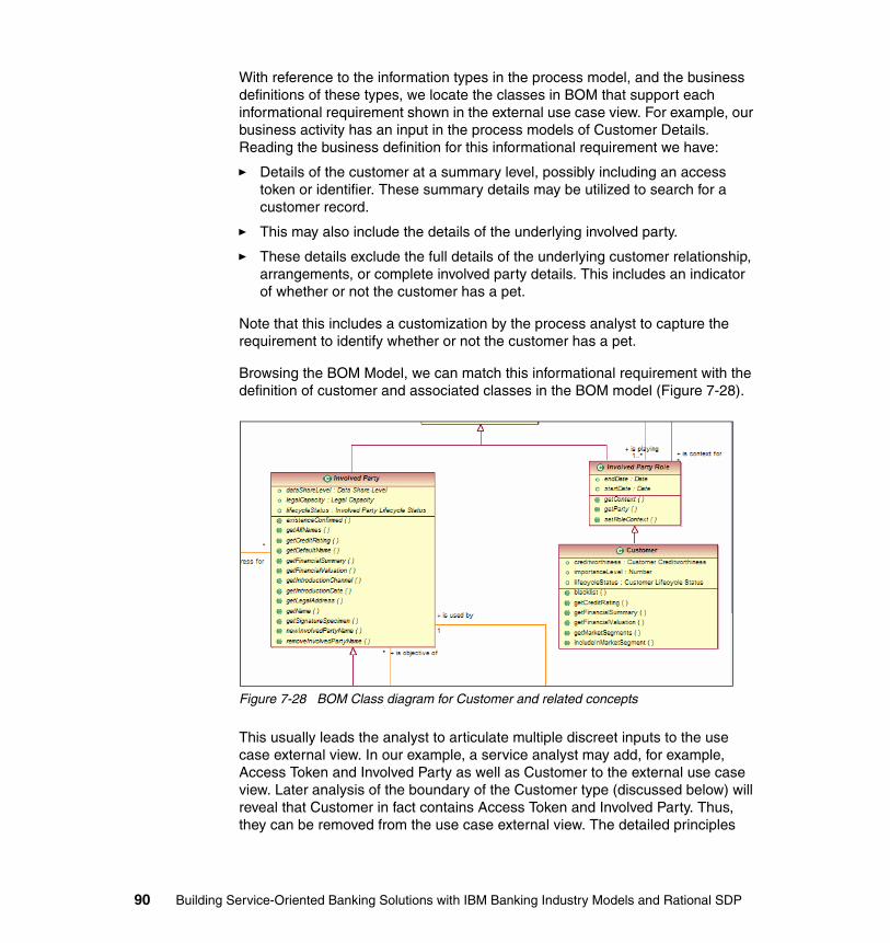
With reference to the information types in the process model, and the business definitions of these types, we locate the classes in BOM that support each informational requirement shown in the external use case view. For example, our business activity has an input in the process models of Customer Details. Reading the business definition for this informational requirement we have:
� Details of the customer at a summary level, possibly including an access token or identifier. These summary details may be utilized to search for a customer record.
� This may also include the details of the underlying involved party.
� These details exclude the full details of the underlying customer relationship, arrangements, or complete involved party details. This includes an indicator of whether or not the customer has a pet.
Note that this includes a customization by the process analyst to capture the requirement to identify whether or not the customer has a pet.
Browsing the BOM Model, we can match this informational requirement with the definition of customer and associated classes in the BOM model (Figure 7-28).
Figure 7-28 BOM Class diagram for Customer and related concepts
This usually leads the analyst to articulate multiple discreet inputs to the use case external view. In our example, a service analyst may add, for example, Access Token and Involved Party as well as Customer to the external use case view. Later analysis of the boundary of the Customer type (discussed below) will reveal that Customer in fact contains Access Token and Involved Party. Thus, they can be removed from the use case external view. The detailed principles
90 Building Service-Oriented Banking Solutions with IBM Banking Industry Models and Rational SDP
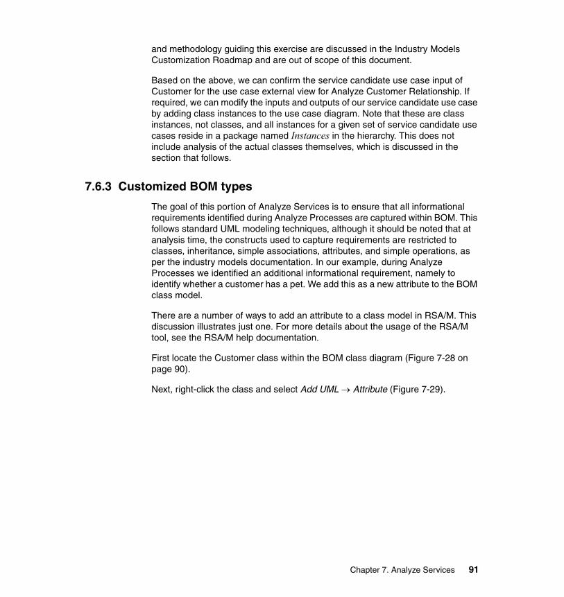
and methodology guiding this exercise are discussed in the Industry Models Customization Roadmap and are out of scope of this document.
Based on the above, we can confirm the service candidate use case input of Customer for the use case external view for Analyze Customer Relationship. If required, we can modify the inputs and outputs of our service candidate use case by adding class instances to the use case diagram. Note that these are class instances, not classes, and all instances for a given set of service candidate use cases reside in a package named Instances in the hierarchy. This does not include analysis of the actual classes themselves, which is discussed in the section that follows.
7.6.3 Customized BOM types
The goal of this portion of Analyze Services is to ensure that all informational requirements identified during Analyze Processes are captured within BOM. This follows standard UML modeling techniques, although it should be noted that at analysis time, the constructs used to capture requirements are restricted to classes, inheritance, simple associations, attributes, and simple operations, as per the industry models documentation. In our example, during Analyze Processes we identified an additional informational requirement, namely to identify whether a customer has a pet. We add this as a new attribute to the BOM class model.
There are a number of ways to add an attribute to a class model in RSA/M. This discussion illustrates just one. For more details about the usage of the RSA/M tool, see the RSA/M help documentation.
First locate the Customer class within the BOM class diagram (Figure 7-28 on page 90).
Next, right-click the class and select Add UML → Attribute (Figure 7-29).
Chapter 7. Analyze Services 91

Figure 7-29 Adding an attribute to BOM
Then enter the details of the attribute in the Properties view: Name (hasPet), type (Boolean) and a textual definition for the attribute (Figure 7-30).
Figure 7-30 Adding an attribute to BOM: Attribute properties
This was a very simple change to the BOM model, based on a very simple requirement. In practice more complex customizations should be expected and carried out in a similar way and in accordance with the industry models documentation.
92 Building Service-Oriented Banking Solutions with IBM Banking Industry Models and Rational SDP
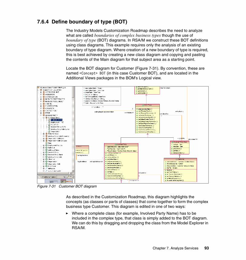
7.6.4 Define boundary of type (BOT)
The Industry Models Customization Roadmap describes the need to analyze what are called boundaries of complex business types though the use of boundary of type (BOT) diagrams. In RSA/M we construct these BOT definitions using class diagrams. This example requires only the analysis of an existing boundary of type diagram. Where creation of a new boundary of type is required, this is best achieved by creating a new class diagram and copying and pasting the contents of the Main diagram for that subject area as a starting point.
Locate the BOT diagram for Customer (Figure 7-31). By convention, these are named <Concept> BOT (in this case Customer BOT), and are located in the Additional Views packages in the BOM's Logical view.
Figure 7-31 Customer BOT diagram
As described in the Customization Roadmap, this diagram highlights the concepts (as classes or parts of classes) that come together to form the complex business type Customer. This diagram is edited in one of two ways:
� Where a complete class (for example, Involved Party Name) has to be included in the complex type, that class is simply added to the BOT diagram. We can do this by dragging and dropping the class from the Model Explorer in RSA/M.
Chapter 7. Analyze Services 93
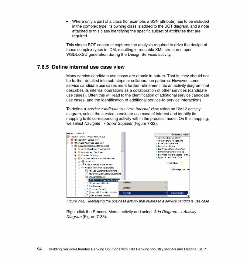
� Where only a part of a class (for example, a SSN attribute) has to be included in the complex type, its owning class is added to the BOT diagram, and a note attached to this class identifying the specific subset of attributes that are required.
This simple BOT construct captures the analysis required to drive the design of these complex types in IDM, resulting in reusable XML structures upon WSDL/XSD generation during the Design Services activity.
7.6.5 Define internal use case view
Many service candidate use cases are atomic in nature. That is, they should not be further detailed into sub-steps or collaboration patterns. However, some service candidate use cases merit further refinement into an activity diagram that describes its internal operations as a collaboration of other services (candidate use cases). Often this will lead to the identification of additional service candidate use cases, and the identification of additional service-to-service interactions.
To define a service candidate use case internal view using an UML2 activity diagram, select the service candidate use case of interest and identify its mapping to its corresponding activity within the process model. On this mapping, we select Navigate → Show Supplier (Figure 7-32).
Figure 7-32 Identifying the business activity that relates to a service candidate use case
Right-click the Process Model activity and select Add Diagram → Activity Diagram (Figure 7-33).
94 Building Service-Oriented Banking Solutions with IBM Banking Industry Models and Rational SDP
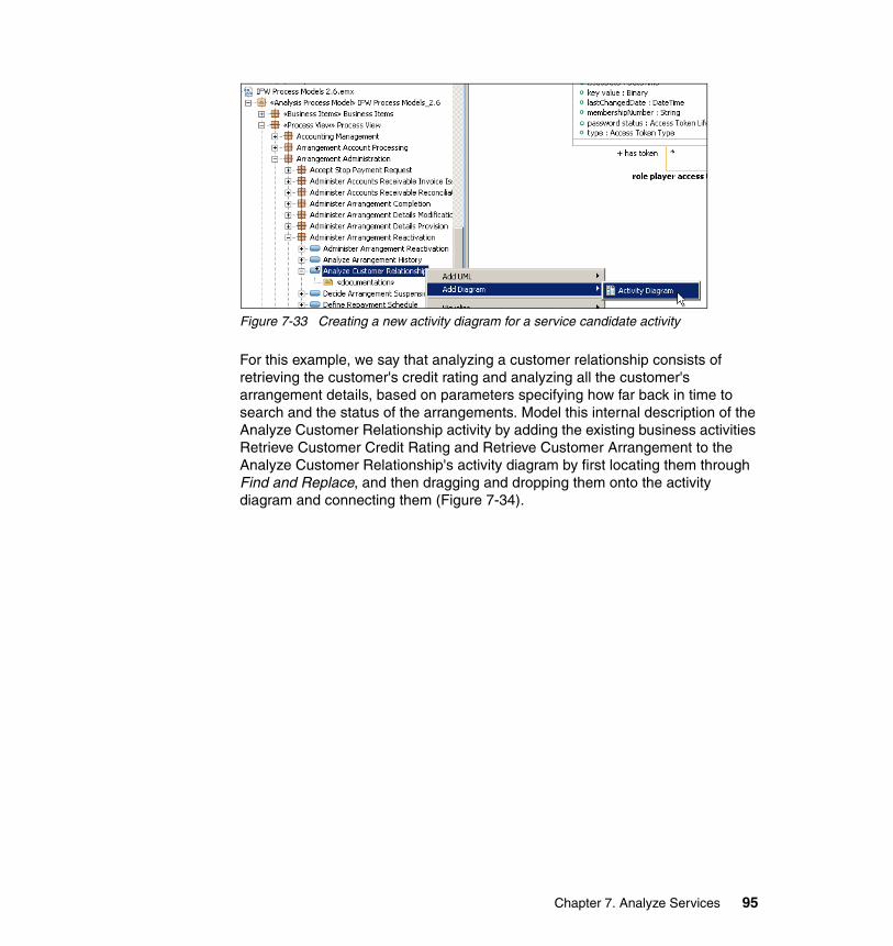
Figure 7-33 Creating a new activity diagram for a service candidate activity
For this example, we say that analyzing a customer relationship consists of retrieving the customer's credit rating and analyzing all the customer's arrangement details, based on parameters specifying how far back in time to search and the status of the arrangements. Model this internal description of the Analyze Customer Relationship activity by adding the existing business activities Retrieve Customer Credit Rating and Retrieve Customer Arrangement to the Analyze Customer Relationship's activity diagram by first locating them through Find and Replace, and then dragging and dropping them onto the activity diagram and connecting them (Figure 7-34).
Chapter 7. Analyze Services 95
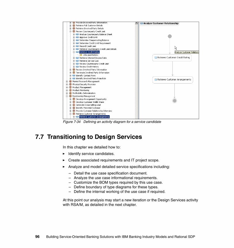
Figure 7-34 Defining an activity diagram for a service candidate
7.7 Transitioning to Design Services
In this chapter we detailed how to:
� Identify service candidates.
� Create associated requirements and IT project scope.
� Analyze and model detailed service specifications including:
– Detail the use case specification document.– Analyze the use case informational requirements.– Customize the BOM types required by this use case.– Define boundary of type diagrams for these types.– Define the internal working of the use case if required.
At this point our analysis may start a new iteration or the Design Services activity with RSA/M, as detailed in the next chapter.
96 Building Service-Oriented Banking Solutions with IBM Banking Industry Models and Rational SDP
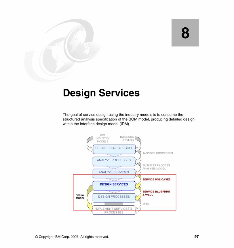
Chapter 8. Design Services
The goal of service design using the industry models is to consume the structured analysis specification of the BOM model, producing detailed design within the interface design model (IDM).
8
DEFINE PROJECT SCOPE
ANALYZE SERVICES
DESIGN SERVICES
DESIGN PROCESSES
IMPLEMENT SERVICES & PROCESSES
ANALYZE PROCESSES
IN-SCOPE PROCESSES
BUSINESS PROCESS ANALYSIS MODEL
SERVICE BLUEPRINT& WSDL
BPEL
SERVICE USE CASES
DESIGNMODEL
IBMINDUSTRYMODELS
BUSINESSDRIVERS
© Copyright IBM Corp. 2007. All rights reserved. 97

8.1 Introduction to Design Services1
The analysis elements in BOM that we want to consume to produce service design are the in-scope service use case2 internal and external views, class model customizations, and boundary of type (BOT) diagrams:
� All service candidate use cases in the BOM that were identified and validated during service analysis must be realized by a component in the design model, IDM. Ideally, every BOM service use case is exposed through an equivalent <<command>> stereotyped operation on a component’s interface in the IDM. This relationship between a BOM service use case and its realization in the IDM is captured in the BOM model as a cross-model (between the BOM and IDM) dependency relationship. In some exception cases, this one-to-one mapping does exist, for example, where design comprises or system constraints dictate that this is not possible. Examples of design comprises include comprises based on capabilities of existing systems including transaction granularity, technical and business architecture, and organizational (budget, timing) and technology constraints. Refer to the industry models Customization Roadmap for guidance on this topic.
� All validated service candidate use case internal views are analyzed to define service (and thus component) interactions in IDM. Note that the internal behavior of a service candidate use case is expressed as an activity diagram, and as such may yield multiple collaborations in IDM. Also, in some cases, it is not necessary to define collaborations in IDM at all, as per the Customization Roadmap.
� Class model customizations in BOM must be analyzed for propagation to IDM. Again, design level constraints and scoping concerns may play a role in this activity. However, some extension of the IDM class model is to be expected.
� BOM BOT diagrams are used to drive the definition of type interfaces in IDM. These type interfaces act to denormalize the models inside the IDM components, presenting useful types to service consumers.
1 Notes: 1) Additional methodological guidance/motivation is available in the IM&A Model Customization Roadmap. 2) Detailed IM&A modeling guidelines for WBM and RSx are available in the IM&A Process and Service Models Metamodel Guide and other related publications. These publications are available to licensees of the IBM Industry Models. Send an e-mail to [email protected] to ask for access.
2 The Analyze Services activities validated that in-scope service candidate use cases are good service candidates and, thus, can now be referred to as services or service use cases. This is a conceptual, not a physical, distinction.
98 Building Service-Oriented Banking Solutions with IBM Banking Industry Models and Rational SDP

The sections that follow carry the scenarios forward through their relevant service design steps. It is normal that some additional documentation besides the raw model be provided to the designer to guide service design work, for example, a statement of which BOM service use cases are in scope for design (utilizing, for example, the RequisitePro project SCOPE traceability). The two examples deal with the modification of an existing service in IDM and the addition of a new service.
8.2 Using IBM Rational SDP to Design Services
The Design Services activities detailed in this chapter are performed in the Rational SDP component Rational Software Architect (RSA), which was introduced in previous chapters.
8.3 Example 1: update Analyze Customer Relationship service in IDM
The Analyze Customer Relationship service candidate use case was modified during service analysis by adding informational requirements and an activity diagram detailing the flow of the use case with respect to collaborating services. Service design refines and realizes the BOM service analysis specification.
8.3.1 Locate service use case in BOM
To locate the service use case in BOM follow these steps:
� Select the BOM Use Case View and Find/Replace (Figure 8-1).
Chapter 8. Design Services 99

Figure 8-1 Locating service use case: step 1
� Enter the name of the required service use case and click OK (Figure 8-2).
Figure 8-2 Locating service use case: step 2
� To open the use case diagram we (1) double-click the service use case name in the Find and Replace query result set, (2) expand the service use case node in the model explorer, and (3) double-click the service use case external view (informational requirements) use case diagram (Figure 8-3).
100 Building Service-Oriented Banking Solutions with IBM Banking Industry Models and Rational SDP

Figure 8-3 Opening a service use case external view use case diagram
8.3.2 Locate the service use case component interface in the IDM
Because this is a predefined IFW service use case, there is already an associated predefined IFW operation on a component interface in the IDM.
� Select the BOM service use case dependency relationship to its IDM component interface and Navigate → Show Supplier (Figure 8-4).
Figure 8-4 Navigating from BOM service use case to its dependent IDM operation
Chapter 8. Design Services 101
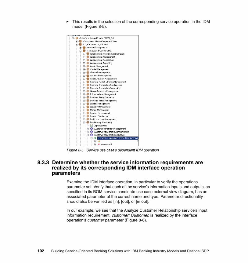
� This results in the selection of the corresponding service operation in the IDM model (Figure 8-5).
Figure 8-5 Service use case’s dependent IDM operation
8.3.3 Determine whether the service information requirements are realized by its corresponding IDM interface operation parameters
Examine the IDM interface operation, in particular to verify the operations parameter set. Verify that each of the service’s information inputs and outputs, as specified in its BOM service candidate use case external view diagram, has an associated parameter of the correct name and type. Parameter directionality should also be verified as [in], [out], or [in out].
In our example, we see that the Analyze Customer Relationship service’s input information requirement, customer: Customer, is realized by the interface operation’s customer parameter (Figure 8-6).
102 Building Service-Oriented Banking Solutions with IBM Banking Industry Models and Rational SDP
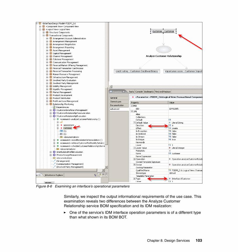
Figure 8-6 Examining an interface’s operational parameters
Similarly, we inspect the output informational requirements of the use case. This examination reveals two differences between the Analyze Customer Relationship service BOM specification and its IDM realization:
� One of the service’s IDM interface operation parameters is of a different type than what shown in its BOM BOT.
Chapter 8. Design Services 103
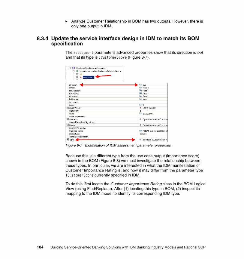
� Analyze Customer Relationship in BOM has two outputs. However, there is only one output in IDM.
8.3.4 Update the service interface design in IDM to match its BOM specification
The assessment parameter’s advanced properties show that its direction is out and that its type is ICustomerScore (Figure 8-7).
Figure 8-7 Examination of IDM assessment parameter properties
Because this is a different type from the use case output (importance score) shown in the BOM (Figure 8-8) we must investigate the relationship between these types. In particular, we are interested in what the IDM manifestation of Customer Importance Rating is, and how it may differ from the parameter type ICustomerScore currently specified in IDM.
To do this, first locate the Customer Importance Rating class in the BOM Logical View (using Find/Replace). After (1) locating this type in BOM, (2) inspect its mapping to the IDM model to identify its corresponding IDM type.
104 Building Service-Oriented Banking Solutions with IBM Banking Industry Models and Rational SDP
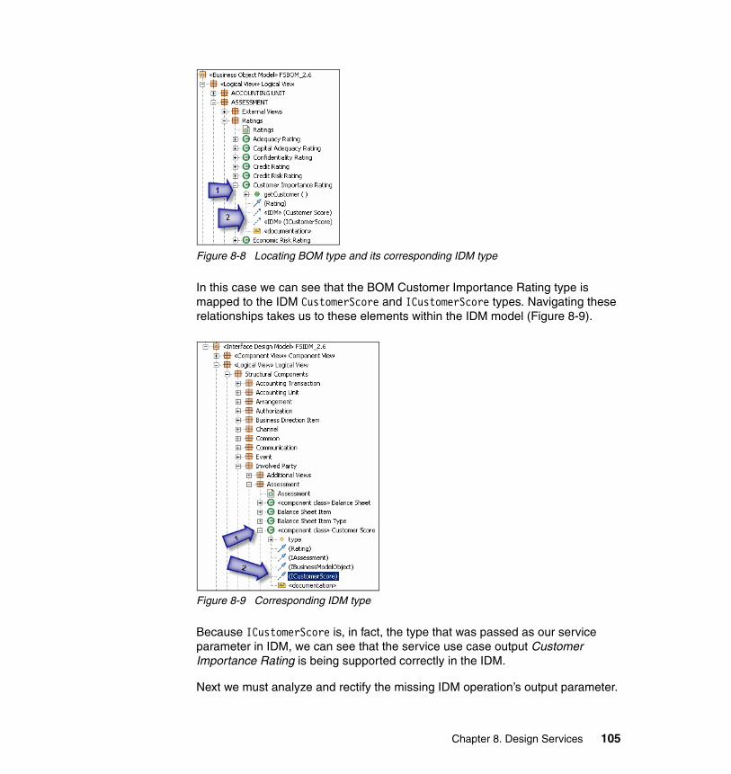
Figure 8-8 Locating BOM type and its corresponding IDM type
In this case we can see that the BOM Customer Importance Rating type is mapped to the IDM CustomerScore and ICustomerScore types. Navigating these relationships takes us to these elements within the IDM model (Figure 8-9).
Figure 8-9 Corresponding IDM type
Because ICustomerScore is, in fact, the type that was passed as our service parameter in IDM, we can see that the service use case output Customer Importance Rating is being supported correctly in the IDM.
Next we must analyze and rectify the missing IDM operation’s output parameter.
Chapter 8. Design Services 105
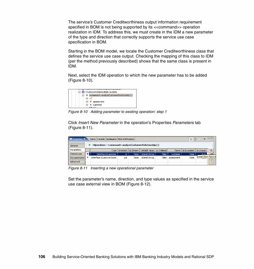
The service’s Customer Creditworthiness output information requirement specified in BOM is not being supported by its <<command>> operation realization in IDM. To address this, we must create in the IDM a new parameter of the type and direction that correctly supports the service use case specification in BOM.
Starting in the BOM model, we locate the Customer Creditworthiness class that defines the service use case output. Checking the mapping of this class to IDM (per the method previously described) shows that the same class is present in IDM.
Next, select the IDM operation to which the new parameter has to be added (Figure 8-10).
Figure 8-10 Adding parameter to existing operation: step 1
Click Insert New Parameter in the operation’s Properties Parameters tab (Figure 8-11).
Figure 8-11 Inserting a new operational parameter
Set the parameter’s name, direction, and type values as specified in the service use case external view in BOM (Figure 8-12).
106 Building Service-Oriented Banking Solutions with IBM Banking Industry Models and Rational SDP
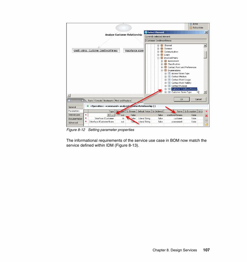
Figure 8-12 Setting parameter properties
The informational requirements of the service use case in BOM now match the service defined within IDM (Figure 8-13).
Chapter 8. Design Services 107
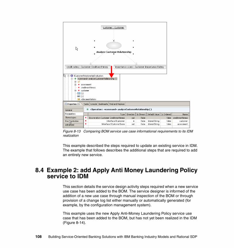
Figure 8-13 Comparing BOM service use case informational requirements to its IDM realization
This example described the steps required to update an existing service in IDM. The example that follows describes the additional steps that are required to add an entirely new service.
8.4 Example 2: add Apply Anti Money Laundering Policy service to IDM
This section details the service design activity steps required when a new service use case has been added to the BOM. The service designer is informed of the addition of a new use case through manual inspection of the BOM or through provision of a change log list either manually or automatically generated (for example, by the configuration management system).
This example uses the new Apply Anti-Money Laundering Policy service use case that has been added to the BOM, but has not yet been realized in the IDM (Figure 8-14).
108 Building Service-Oriented Banking Solutions with IBM Banking Industry Models and Rational SDP

Figure 8-14 Verifying that a BOM service use case is (or is not) in IDM
8.4.1 Determine where service use case realization is located in IDM
The first question to answer when determining where in the IDM to locate the new service is: What type of service is this? There are three service classifications in IDM: Structural, Transactional, and Utility, provided by corresponding levels of component (Figure 8-15).
Figure 8-15 Levels of components in IDM
Guidance on how to make this determination is provided in the customization roadmap. This section shows how to implement the decisions based on this guidance. For this example, the determination is that Apply Anti Money Laundering Policy belongs to a Transactional component.
The next question to answer is: From a logical perspective, what part of the business (or business component) does this service belong to? In this example, the question is: What part of the business does Apply Anti Money Laundering Policy logically belong to?
Chapter 8. Design Services 109

This decision utilizes the designer’s knowledge informed by experience and reading the documentation fields of the model elements, as well as the knowledge of the structure and content of the design model. For this example, the determination is that Apply Anti Money Laundering Policy is related to Risk Management (Figure 8-16).
Figure 8-16 Locating a component for a new IDM service
It is possible that the existing component blueprint of IDM does not provide a suitable location for the new service, in which case a new component should be added. This involves the addition of a package in the IDM Logical View, and a corresponding component in the component view (reference the sub-section later in this chapter on maintenance of component dependencies).
Within each component of IDM is a set of interfaces. Each interface further breaks the component’s responsibilities up into additional business areas. To add a new service, we must identify which interface we should select. In some cases the existing interfaces of IDM do not provide a suitable candidate, so we must add a new interface.
8.4.2 Add new IDM interface
For this example, the determination is that Apply Anti Money Laundering Policy requires a new interface, IAMLPolicyApplication, in the Risk Management component (Figure 8-17).
110 Building Service-Oriented Banking Solutions with IBM Banking Industry Models and Rational SDP
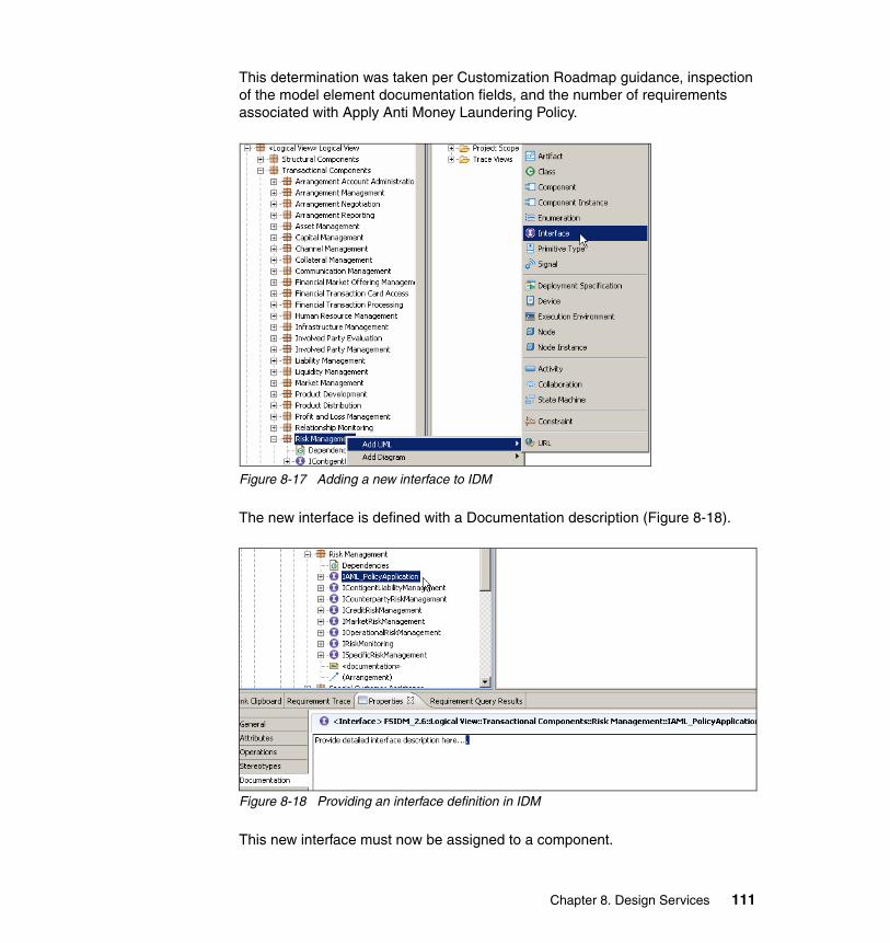
This determination was taken per Customization Roadmap guidance, inspection of the model element documentation fields, and the number of requirements associated with Apply Anti Money Laundering Policy.
Figure 8-17 Adding a new interface to IDM
The new interface is defined with a Documentation description (Figure 8-18).
Figure 8-18 Providing an interface definition in IDM
This new interface must now be assigned to a component.
Chapter 8. Design Services 111
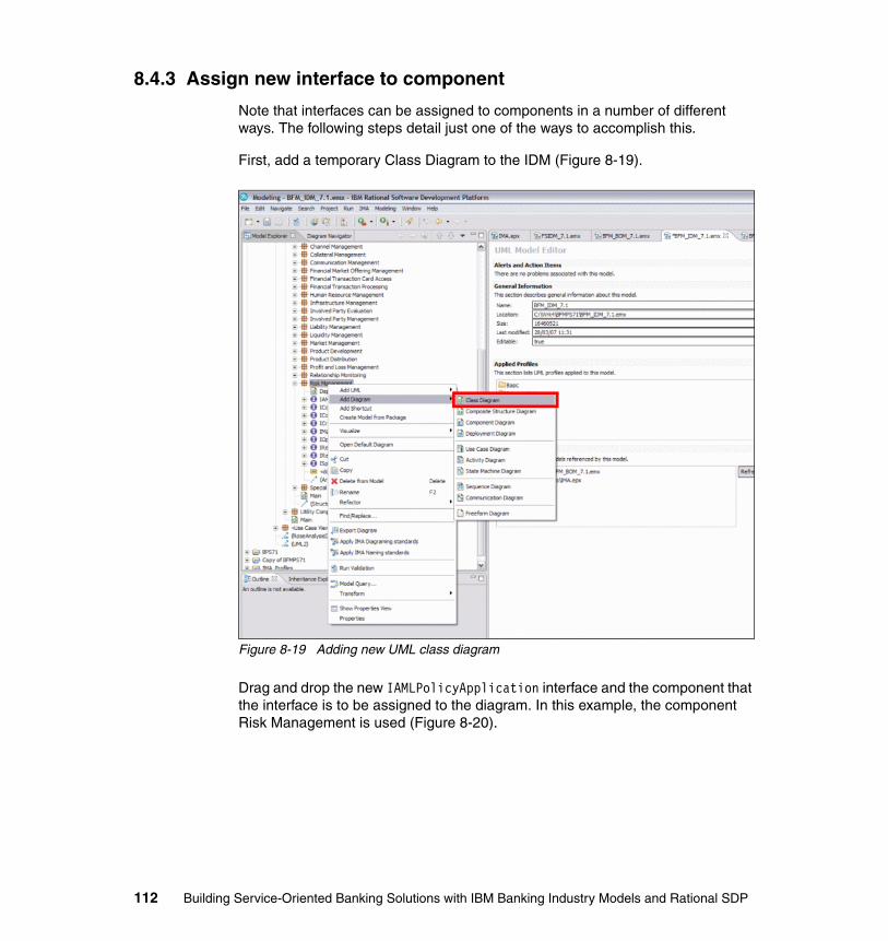
8.4.3 Assign new interface to component
Note that interfaces can be assigned to components in a number of different ways. The following steps detail just one of the ways to accomplish this.
First, add a temporary Class Diagram to the IDM (Figure 8-19).
Figure 8-19 Adding new UML class diagram
Drag and drop the new IAMLPolicyApplication interface and the component that the interface is to be assigned to the diagram. In this example, the component Risk Management is used (Figure 8-20).
112 Building Service-Oriented Banking Solutions with IBM Banking Industry Models and Rational SDP

Figure 8-20 Adding IDM interface and component to class diagram
Select the Realization relationship in the palette and add the realization relationship from the component to the interface (Figure 8-21).
Figure 8-21 Adding a realization relationship
Chapter 8. Design Services 113
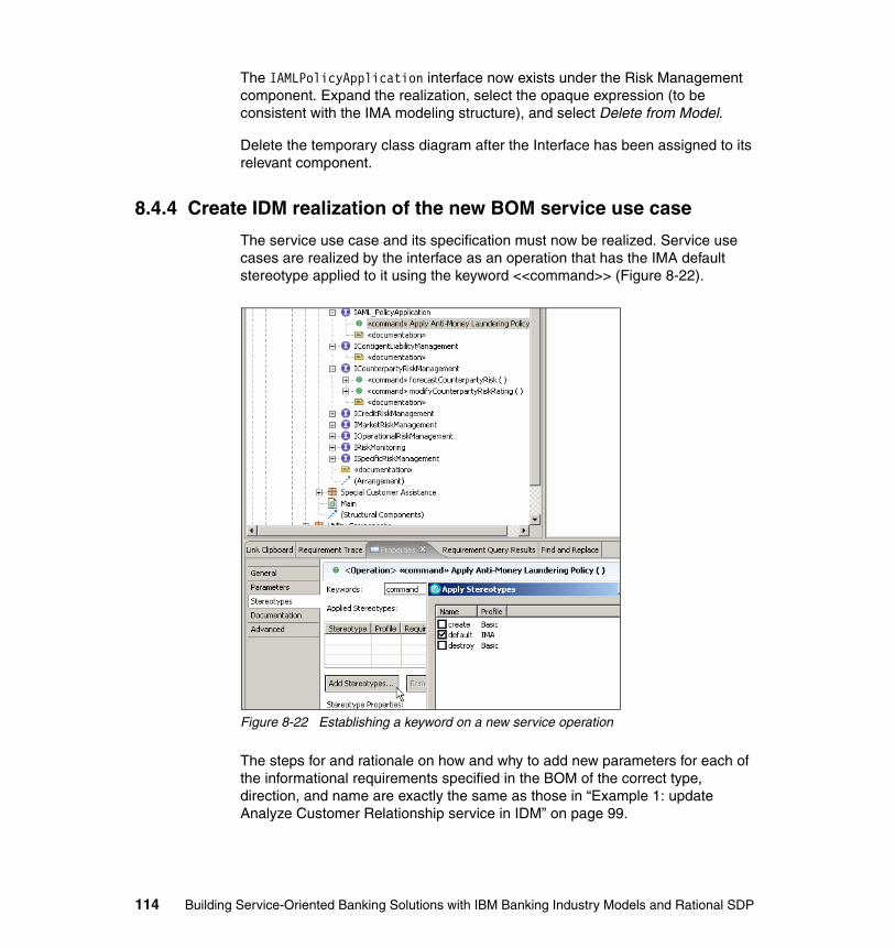
The IAMLPolicyApplication interface now exists under the Risk Management component. Expand the realization, select the opaque expression (to be consistent with the IMA modeling structure), and select Delete from Model.
Delete the temporary class diagram after the Interface has been assigned to its relevant component.
8.4.4 Create IDM realization of the new BOM service use case
The service use case and its specification must now be realized. Service use cases are realized by the interface as an operation that has the IMA default stereotype applied to it using the keyword <<command>> (Figure 8-22).
Figure 8-22 Establishing a keyword on a new service operation
The steps for and rationale on how and why to add new parameters for each of the informational requirements specified in the BOM of the correct type, direction, and name are exactly the same as those in “Example 1: update Analyze Customer Relationship service in IDM” on page 99.
114 Building Service-Oriented Banking Solutions with IBM Banking Industry Models and Rational SDP
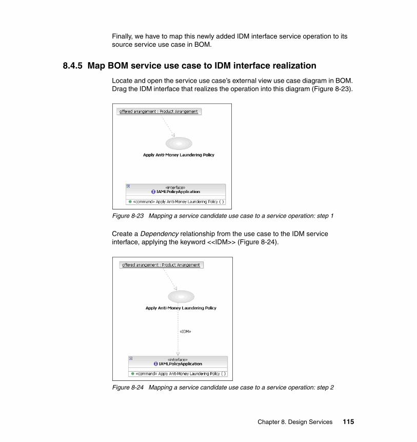
Finally, we have to map this newly added IDM interface service operation to its source service use case in BOM.
8.4.5 Map BOM service use case to IDM interface realization
Locate and open the service use case’s external view use case diagram in BOM. Drag the IDM interface that realizes the operation into this diagram (Figure 8-23).
Figure 8-23 Mapping a service candidate use case to a service operation: step 1
Create a Dependency relationship from the use case to the IDM service interface, applying the keyword <<IDM>> (Figure 8-24).
Figure 8-24 Mapping a service candidate use case to a service operation: step 2
Chapter 8. Design Services 115

Select the dependency relationship and Properties → Supplier (Figure 8-25).
Figure 8-25 Mapping a service use case to a service operation: step 3
Add a new supplier navigating to the actual service candidate operation, and then delete the supplier for the interface (Figure 8-26).
Figure 8-26 Mapping a service use case to a service operation: step 4
116 Building Service-Oriented Banking Solutions with IBM Banking Industry Models and Rational SDP

Finally, remove the interface from the use case external view diagram by selecting the interface and Delete from Diagram.
8.5 Construct IDM collaborations from BOM internal use case views
Having established a corresponding service interface in IDM for the BOM service use case, the internal workings of the service use case must be analyzed, if any exist. In BOM this is expressed as an Internal Use Case View3—an activity diagram located within the service use case in the model explorer. This activity diagram may contain activities that themselves are service use cases in BOM. This collaboration manifests as a service-to-service invocation in IDM, expressed through a communication (collaboration)4 diagram.
During service analysis we added two (sub-)activities to the Internal Use Case View of the service candidate use case Analyze Customer Relationship. We also discussed that these sub-activities could themselves be analyzed and could result in new service candidate use cases. In our Analyze Customer Relationship example, the resulting IDM service operation for Analyze Customer Relationship invokes the resulting IDM service operations for each of the two sub-activities. This interaction is described using a communication diagram (Figure 8-27). Refer to the Customization Roadmap for details on the relationship between activity diagrams in the BOM and collaborations in the IDM.
For the Analyze Customer Relationship service, we have to create a new collaboration to detail the service interactions specified in its BOM activity diagram.
3 An activity diagram describing the internal flow of a service candidate use case logically belongs in the BOM—and this is how we refer to it in this paper. However, due to RSA/M capabilities with respect to multiple models, a service candidate’s activity diagram that describes the interaction between business activities and business items that describe the required behavior of the service candidate use case are located in the IFW Process Model. Reference Chapter 7, “Analyze Services” on page 61, for details on creating Service Candidate Internal Use Case Views in the IFW Process Model using RSA/M.
4 Collaboration diagrams are called communication diagrams—a type of interaction diagram—in UML 2.0. Collaborations in UML 2.0 are described by interaction diagrams that are contained within an interaction node in RSA.
Chapter 8. Design Services 117
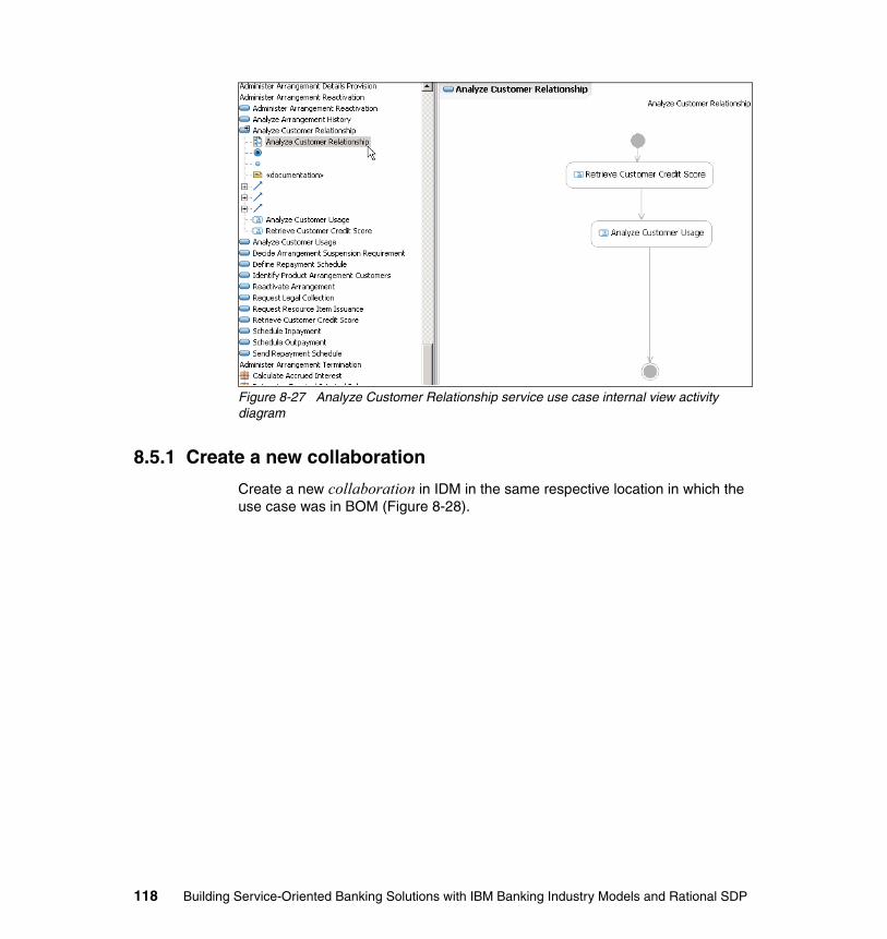
Figure 8-27 Analyze Customer Relationship service use case internal view activity diagram
8.5.1 Create a new collaboration
Create a new collaboration in IDM in the same respective location in which the use case was in BOM (Figure 8-28).
118 Building Service-Oriented Banking Solutions with IBM Banking Industry Models and Rational SDP

Figure 8-28 Creating a collaboration in IDM
Add a communication diagram to the new collaboration (Figure 8-29).
Chapter 8. Design Services 119
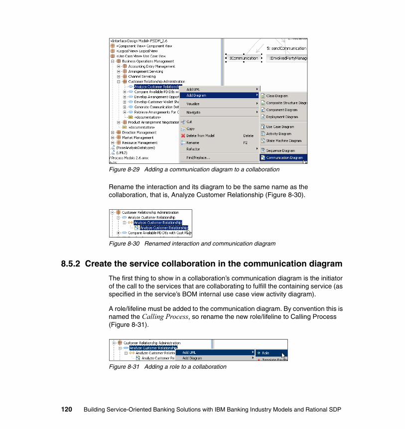
Figure 8-29 Adding a communication diagram to a collaboration
Rename the interaction and its diagram to be the same name as the collaboration, that is, Analyze Customer Relationship (Figure 8-30).
Figure 8-30 Renamed interaction and communication diagram
8.5.2 Create the service collaboration in the communication diagram
The first thing to show in a collaboration’s communication diagram is the initiator of the call to the services that are collaborating to fulfill the containing service (as specified in the service’s BOM internal use case view activity diagram).
A role/lifeline must be added to the communication diagram. By convention this is named the Calling Process, so rename the new role/lifeline to Calling Process (Figure 8-31).
Figure 8-31 Adding a role to a collaboration
120 Building Service-Oriented Banking Solutions with IBM Banking Industry Models and Rational SDP

Then drag and drop this Calling Process role/lifeline into the communication diagram (alternatively, drag and drop lifeline from the tool palette) (Figure 8-32).
Figure 8-32 Adding Calling Process role to the collaboration’s communication diagram
We have to add to the communication diagram the interface that contains the service operation that invokes the collaboration. Do this by locating in IDM the interface with operation of interest, drag and drop the interface to the communication diagram, and then remove the role name (making the role an anonymous instance).
All roles added to the collaboration must be anonymous (un-named). Adding roles in this way ensures that their type is set correctly (to the type of the interface that contains the operation).
In this example, add the «» ICustomerRelationshipEvaluation interface, which contains the «command» analyzeCustomerRelationship operation, to the collaboration’s communication diagram. First locate the interface in the IDM Logical View, then drag and drop it into the communication diagram. Then go to the new role’s Properties and delete its name (Figure 8-33).
Chapter 8. Design Services 121
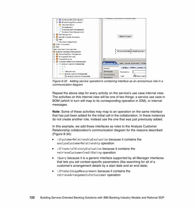
Figure 8-33 Adding service operation’s containing interface as an anonymous role in a communication diagram
Repeat the above step for every activity on the service’s use case internal view. The activities on this internal view will be one of two things: a service use case in BOM (which in turn will map to its corresponding operation in IDM), or internal messages.
Note: Some of these activities may map to an operation on the same interface that has just been added for the initial call in the collaboration. In these instances do not create another role. Instead use the one that was just previously added.
In this example, we add these interfaces as roles to the Analyze Customer Relationship collaboration’s communication diagram for the reasons described (Figure 8-34):
� :ICustomerRelationshipEvaluation because it contains the analyzeCustomerRelationship operation
� :IFinancialHistoryEvaluation because it contains the retrieveCustomerCreditRating operation
� iQuery because it is a generic interface supported by all Manager interfaces that lets you set context-specific parameters (like searching for all of a customer’s arrangement details by a start date and an end date)
� :IProductUsageMeasurement because it contains the retrieveArrangementsForCustomer operation
122 Building Service-Oriented Banking Solutions with IBM Banking Industry Models and Rational SDP
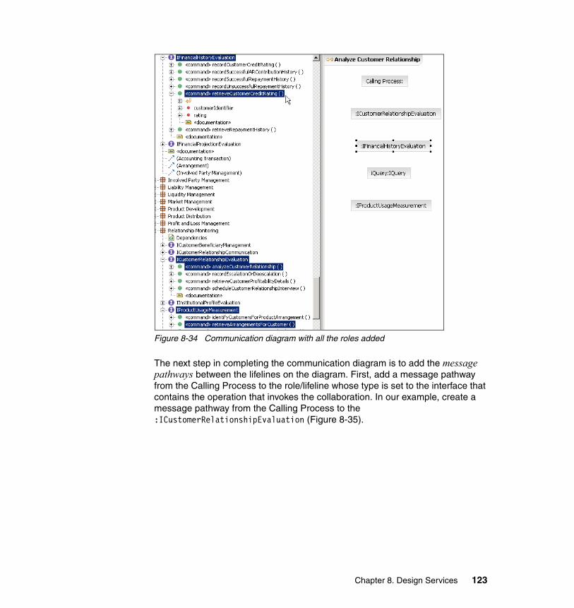
Figure 8-34 Communication diagram with all the roles added
The next step in completing the communication diagram is to add the message pathways between the lifelines on the diagram. First, add a message pathway from the Calling Process to the role/lifeline whose type is set to the interface that contains the operation that invokes the collaboration. In our example, create a message pathway from the Calling Process to the :ICustomerRelationshipEvaluation (Figure 8-35).
Chapter 8. Design Services 123
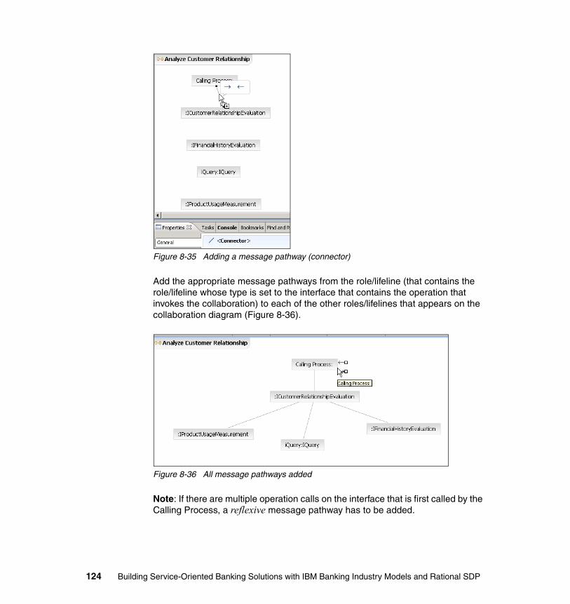
Figure 8-35 Adding a message pathway (connector)
Add the appropriate message pathways from the role/lifeline (that contains the role/lifeline whose type is set to the interface that contains the operation that invokes the collaboration) to each of the other roles/lifelines that appears on the collaboration diagram (Figure 8-36).
Figure 8-36 All message pathways added
Note: If there are multiple operation calls on the interface that is first called by the Calling Process, a reflexive message pathway has to be added.
124 Building Service-Oriented Banking Solutions with IBM Banking Industry Models and Rational SDP
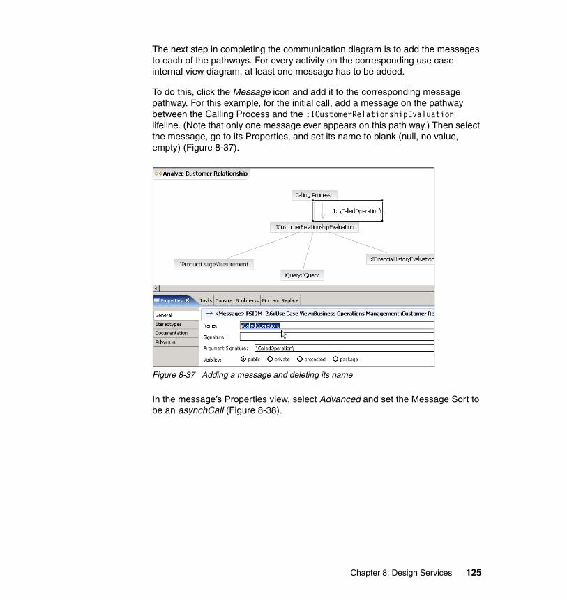
The next step in completing the communication diagram is to add the messages to each of the pathways. For every activity on the corresponding use case internal view diagram, at least one message has to be added.
To do this, click the Message icon and add it to the corresponding message pathway. For this example, for the initial call, add a message on the pathway between the Calling Process and the :ICustomerRelationshipEvaluation lifeline. (Note that only one message ever appears on this path way.) Then select the message, go to its Properties, and set its name to blank (null, no value, empty) (Figure 8-37).
Figure 8-37 Adding a message and deleting its name
In the message’s Properties view, select Advanced and set the Message Sort to be an asynchCall (Figure 8-38).
Chapter 8. Design Services 125
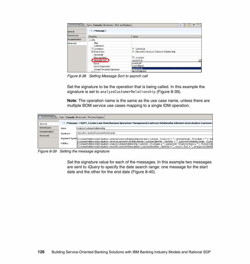
Figure 8-38 Setting Message Sort to asynch call
Set the signature to be the operation that is being called. In this example the signature is set to analyzeCustomerRelationship (Figure 8-39).
Note: The operation name is the same as the use case name, unless there are multiple BOM service use cases mapping to a single IDM operation.
Figure 8-39 Setting the message signature
Set the signature value for each of the messages. In this example two messages are sent to iQuery to specify the date search range: one message for the start date and the other for the end date (Figure 8-40).
126 Building Service-Oriented Banking Solutions with IBM Banking Industry Models and Rational SDP
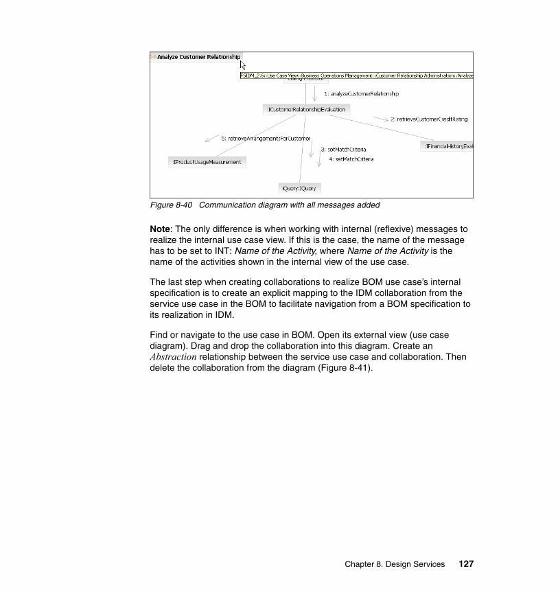
Figure 8-40 Communication diagram with all messages added
Note: The only difference is when working with internal (reflexive) messages to realize the internal use case view. If this is the case, the name of the message has to be set to INT: Name of the Activity, where Name of the Activity is the name of the activities shown in the internal view of the use case.
The last step when creating collaborations to realize BOM use case’s internal specification is to create an explicit mapping to the IDM collaboration from the service use case in the BOM to facilitate navigation from a BOM specification to its realization in IDM.
Find or navigate to the use case in BOM. Open its external view (use case diagram). Drag and drop the collaboration into this diagram. Create an Abstraction relationship between the service use case and collaboration. Then delete the collaboration from the diagram (Figure 8-41).
Chapter 8. Design Services 127
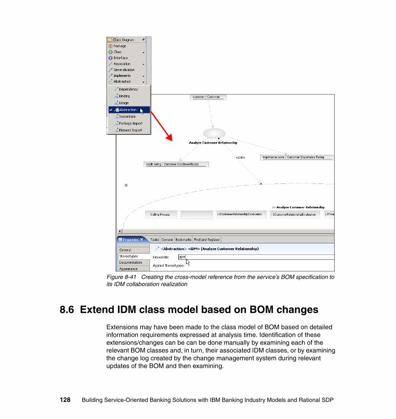
Figure 8-41 Creating the cross-model reference from the service’s BOM specification to its IDM collaboration realization
8.6 Extend IDM class model based on BOM changes
Extensions may have been made to the class model of BOM based on detailed information requirements expressed at analysis time. Identification of these extensions/changes can be can be done manually by examining each of the relevant BOM classes and, in turn, their associated IDM classes, or by examining the change log created by the change management system during relevant updates of the BOM and then examining.
128 Building Service-Oriented Banking Solutions with IBM Banking Industry Models and Rational SDP
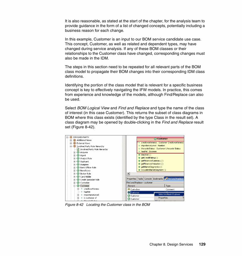
It is also reasonable, as stated at the start of the chapter, for the analysis team to provide guidance in the form of a list of changed concepts, potentially including a business reason for each change.
In this example, Customer is an input to our BOM service candidate use case. This concept, Customer, as well as related and dependent types, may have changed during service analysis. If any of these BOM classes or their relationships to the Customer class have changed, corresponding changes must also be made in the IDM.
The steps in this section need to be repeated for all relevant parts of the BOM class model to propagate their BOM changes into their corresponding IDM class definitions.
Identifying the portion of the class model that is relevant for a specific business concept is key to effectively navigating the IFW models. In practice, this comes from experience and knowledge of the models, although Find/Replace can also be used.
Select BOM Logical View and Find and Replace and type the name of the class of interest (in this case Customer). This returns the subset of class diagrams in BOM where this class exists (identified by the type Class in the result set). A class diagram may be opened by double-clicking in the Find and Replace result set (Figure 8-42).
Figure 8-42 Locating the Customer class in the BOM
Chapter 8. Design Services 129
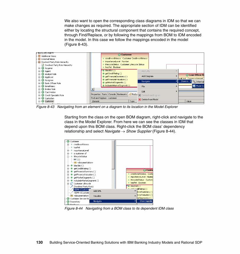
We also want to open the corresponding class diagrams in IDM so that we can make changes as required. The appropriate section of IDM can be identified either by locating the structural component that contains the required concept, through Find/Replace, or by following the mappings from BOM to IDM encoded in the model. In this case we follow the mappings encoded in the model (Figure 8-43).
Figure 8-43 Navigating from an element on a diagram to its location in the Model Explorer
Starting from the class on the open BOM diagram, right-click and navigate to the class in the Model Explorer. From here we can see the classes in IDM that depend upon this BOM class. Right-click the BOM class’ dependency relationship and select Navigate → Show Supplier (Figure 8-44).
Figure 8-44 Navigating from a BOM class to its dependent IDM class
130 Building Service-Oriented Banking Solutions with IBM Banking Industry Models and Rational SDP
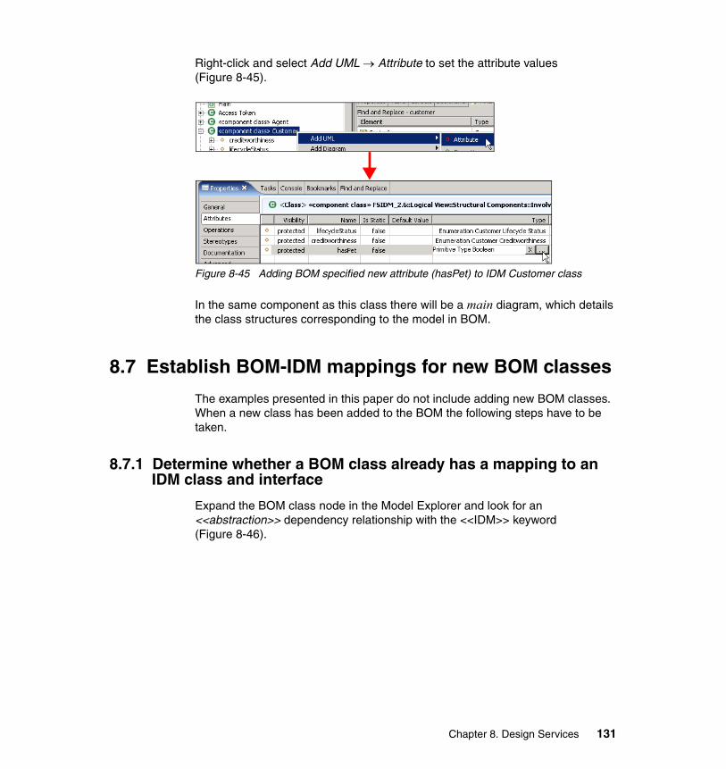
Right-click and select Add UML → Attribute to set the attribute values (Figure 8-45).
Figure 8-45 Adding BOM specified new attribute (hasPet) to IDM Customer class
In the same component as this class there will be a main diagram, which details the class structures corresponding to the model in BOM.
8.7 Establish BOM-IDM mappings for new BOM classes
The examples presented in this paper do not include adding new BOM classes. When a new class has been added to the BOM the following steps have to be taken.
8.7.1 Determine whether a BOM class already has a mapping to an IDM class and interface
Expand the BOM class node in the Model Explorer and look for an <<abstraction>> dependency relationship with the <<IDM>> keyword (Figure 8-46).
Chapter 8. Design Services 131
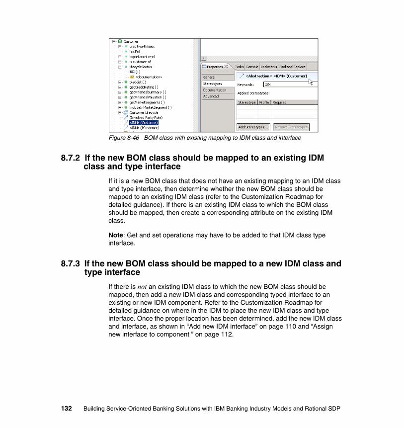
Figure 8-46 BOM class with existing mapping to IDM class and interface
8.7.2 If the new BOM class should be mapped to an existing IDM class and type interface
If it is a new BOM class that does not have an existing mapping to an IDM class and type interface, then determine whether the new BOM class should be mapped to an existing IDM class (refer to the Customization Roadmap for detailed guidance). If there is an existing IDM class to which the BOM class should be mapped, then create a corresponding attribute on the existing IDM class.
Note: Get and set operations may have to be added to that IDM class type interface.
8.7.3 If the new BOM class should be mapped to a new IDM class and type interface
If there is not an existing IDM class to which the new BOM class should be mapped, then add a new IDM class and corresponding typed interface to an existing or new IDM component. Refer to the Customization Roadmap for detailed guidance on where in the IDM to place the new IDM class and type interface. Once the proper location has been determined, add the new IDM class and interface, as shown in “Add new IDM interface” on page 110 and “Assign new interface to component ” on page 112.
132 Building Service-Oriented Banking Solutions with IBM Banking Industry Models and Rational SDP
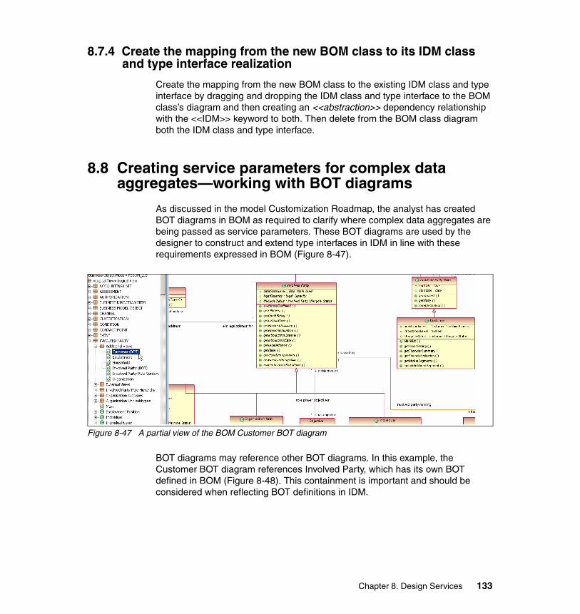
8.7.4 Create the mapping from the new BOM class to its IDM class and type interface realization
Create the mapping from the new BOM class to the existing IDM class and type interface by dragging and dropping the IDM class and type interface to the BOM class’s diagram and then creating an <<abstraction>> dependency relationship with the <<IDM>> keyword to both. Then delete from the BOM class diagram both the IDM class and type interface.
8.8 Creating service parameters for complex data aggregates—working with BOT diagrams
As discussed in the model Customization Roadmap, the analyst has created BOT diagrams in BOM as required to clarify where complex data aggregates are being passed as service parameters. These BOT diagrams are used by the designer to construct and extend type interfaces in IDM in line with these requirements expressed in BOM (Figure 8-47).
Figure 8-47 A partial view of the BOM Customer BOT diagram
BOT diagrams may reference other BOT diagrams. In this example, the Customer BOT diagram references Involved Party, which has its own BOT defined in BOM (Figure 8-48). This containment is important and should be considered when reflecting BOT definitions in IDM.
Chapter 8. Design Services 133
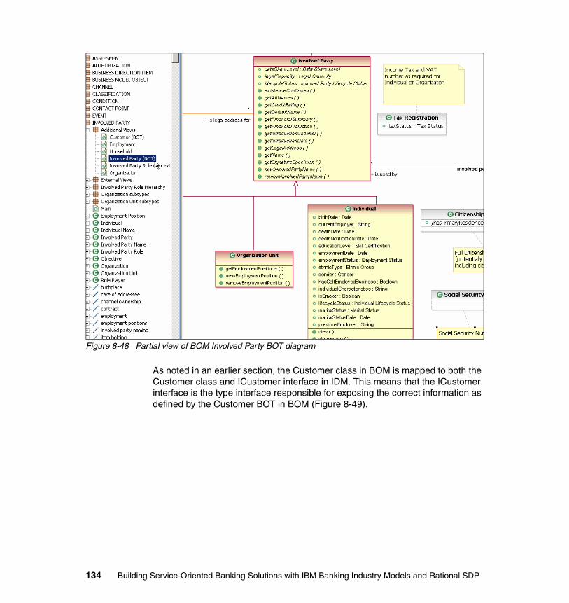
Figure 8-48 Partial view of BOM Involved Party BOT diagram
As noted in an earlier section, the Customer class in BOM is mapped to both the Customer class and ICustomer interface in IDM. This means that the ICustomer interface is the type interface responsible for exposing the correct information as defined by the Customer BOT in BOM (Figure 8-49).
134 Building Service-Oriented Banking Solutions with IBM Banking Industry Models and Rational SDP
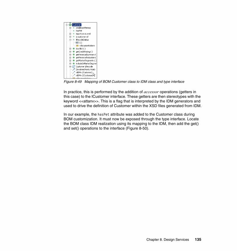
Figure 8-49 Mapping of BOM Customer class to IDM class and type interface
In practice, this is performed by the addition of accessor operations (getters in this case) to the ICustomer interface. These getters are then stereotypes with the keyword <<attanv>>. This is a flag that is interpreted by the IDM generators and used to drive the definition of Customer within the XSD files generated from IDM.
In our example, the hasPet attribute was added to the Customer class during BOM customization. It must now be exposed through the type interface. Locate the BOM class IDM realization using its mapping to the IDM, then add the get() and set() operations to the interface (Figure 8-50).
Chapter 8. Design Services 135

Figure 8-50 ICustomer with new getHasPet operation added
If a new type interface was added (as previously described), then after the mapping of the BOM class to the new interface has been established (as previously described), add the necessary get() and set() operations.
8.9 Updating component dependencies
A component is a physical and replaceable part of a system that conforms to and provides the realization of a set of interfaces (Booch 1999).
Components are internally implemented by a set of component classes and dependent types that support the services outlined in the interfaces exposed by the component. They exude the following characteristics:
� Encapsulated—Separate the definition of services from the implementation of those services.
136 Building Service-Oriented Banking Solutions with IBM Banking Industry Models and Rational SDP
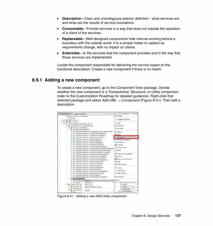
� Descriptive—Clear and unambiguous exterior definition - what services are and what are the results of service invocations.
� Consumable—Provide services in a way that does not impede the operation of a client of the services.
� Replaceable—Well-designed components hide internal working behind a boundary with the outside world. It is a simple matter to replace as requirements change, with no impact on clients.
� Extensible—In the services that the component provides and in the way that those services are implemented.
Locate the component responsible for delivering the service based on the functional description. Create a new component if there is no match.
8.9.1 Adding a new component
To create a new component, go to the Component View package. Decide whether the new component is a Transactional, Structural, or Utility component (refer to the Customization Roadmap for detailed guidance). Right-click that selected package and select Add UML → Component (Figure 8-51). Then add a description.
Figure 8-51 Adding a new IDM Utility component
Chapter 8. Design Services 137
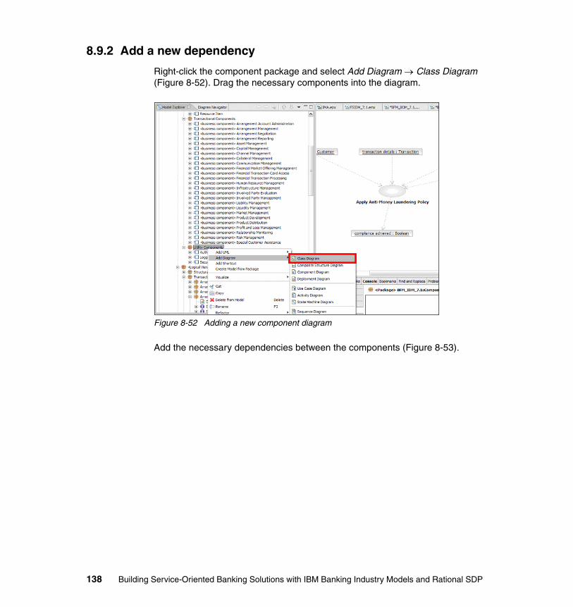
8.9.2 Add a new dependency
Right-click the component package and select Add Diagram → Class Diagram (Figure 8-52). Drag the necessary components into the diagram.
Figure 8-52 Adding a new component diagram
Add the necessary dependencies between the components (Figure 8-53).
138 Building Service-Oriented Banking Solutions with IBM Banking Industry Models and Rational SDP
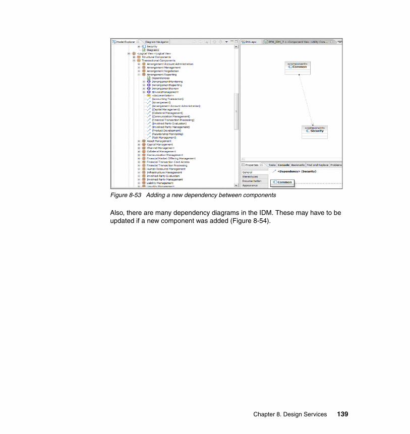
Figure 8-53 Adding a new dependency between components
Also, there are many dependency diagrams in the IDM. These may have to be updated if a new component was added (Figure 8-54).
Chapter 8. Design Services 139
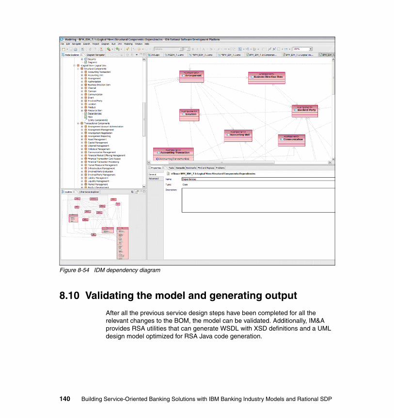
Figure 8-54 IDM dependency diagram
8.10 Validating the model and generating output
After all the previous service design steps have been completed for all the relevant changes to the BOM, the model can be validated. Additionally, IM&A provides RSA utilities that can generate WSDL with XSD definitions and a UML design model optimized for RSA Java code generation.
140 Building Service-Oriented Banking Solutions with IBM Banking Industry Models and Rational SDP
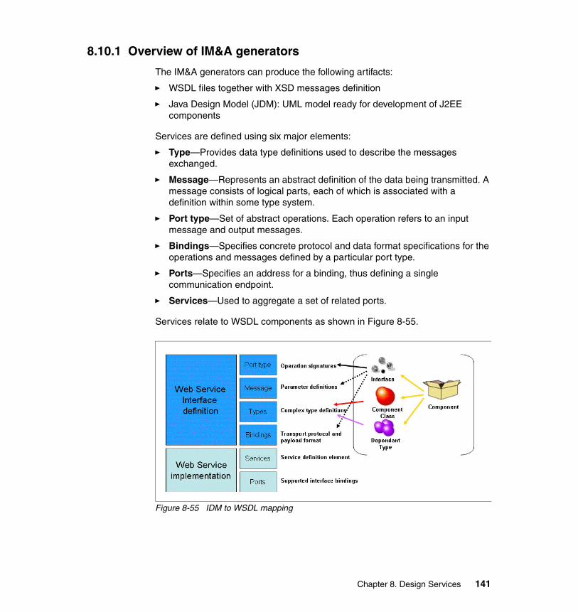
8.10.1 Overview of IM&A generators
The IM&A generators can produce the following artifacts:
� WSDL files together with XSD messages definition
� Java Design Model (JDM): UML model ready for development of J2EE components
Services are defined using six major elements:
� Type—Provides data type definitions used to describe the messages exchanged.
� Message—Represents an abstract definition of the data being transmitted. A message consists of logical parts, each of which is associated with a definition within some type system.
� Port type—Set of abstract operations. Each operation refers to an input message and output messages.
� Bindings—Specifies concrete protocol and data format specifications for the operations and messages defined by a particular port type.
� Ports—Specifies an address for a binding, thus defining a single communication endpoint.
� Services—Used to aggregate a set of related ports.
Services relate to WSDL components as shown in Figure 8-55.
Figure 8-55 IDM to WSDL mapping
Chapter 8. Design Services 141
IDM interface and operations:
� Interfaces in IDM are an expression of a set of services that are logically related. Interfaces are supported by components in IDM, providing an implementation of the services expressed by the interfaces through the component classes and dependent types of the component. Components in IDM clearly separate the expression of the services they provide from the implementation of those services, according to the principle of encapsulation.
� Transactional component interfaces name maps to the port type in the generated WSDL.
� Interfaces are an expression of a set of services that are logically related.
� Interfaces are supported by components.
� Components provide an implementation of the services expressed by the interfaces through the component classes and dependent types of the component.
� Components clearly separate the expression of the services they provide from the implementation of those services, according to the principle of encapsulation.
� Transactional component interfaces name maps to the port type in the generated WSDL.
8.10.2 Overview of the IM&A Java Design Model (JDM)
The Java Design Model is a platform-specific model geared towards the deployment of J2EE components. The JDM is derived from the interface design model (IDM), which is a platform-independent model defining highly interoperable enterprise components exposing services via a set of interfaces.
The JDM provides the definition of transfer, service, and domain object Java classes, which respectively support transfer object, session facade, application service, and business object core J2EE design patterns.
J2EE defines standards for developing, deploying, and executing multi-tiered enterprise applications.
J2EE specification divides the application logic into separate components based on their functional responsibility. These components are then installed on different machines depending on the tier to which the application component belongs.
The J2EE specification defines the following J2EE components:
� The application clients and applets components from the client tier and running on the client machine.
142 Building Service-Oriented Banking Solutions with IBM Banking Industry Models and Rational SDP
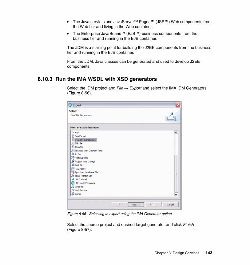
� The Java servlets and JavaServer™ Pages™ (JSP™) Web components from the Web tier and living in the Web container.
� The Enterprise JavaBeans™ (EJB™) business components from the business tier and running in the EJB container.
The JDM is a starting point for building the J2EE components from the business tier and running in the EJB container.
From the JDM, Java classes can be generated and used to develop J2EE components.
8.10.3 Run the IMA WSDL with XSD generators
Select the IDM project and File → Export and select the IMA IDM Generators (Figure 8-56).
Figure 8-56 Selecting to export using the IMA Generator option
Select the source project and desired target generator and click Finish (Figure 8-57).
Chapter 8. Design Services 143

Figure 8-57 Selecting source project and export target generator
Now select the components that you want to export and click Generate (Figure 8-58).
Figure 8-58 Selecting components to export
Specify the export options (Figure 8-59).
144 Building Service-Oriented Banking Solutions with IBM Banking Industry Models and Rational SDP
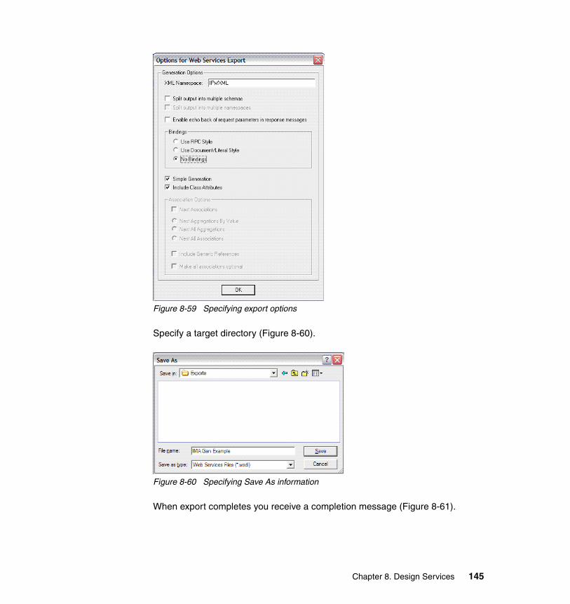
Figure 8-59 Specifying export options
Specify a target directory (Figure 8-60).
Figure 8-60 Specifying Save As information
When export completes you receive a completion message (Figure 8-61).
Chapter 8. Design Services 145
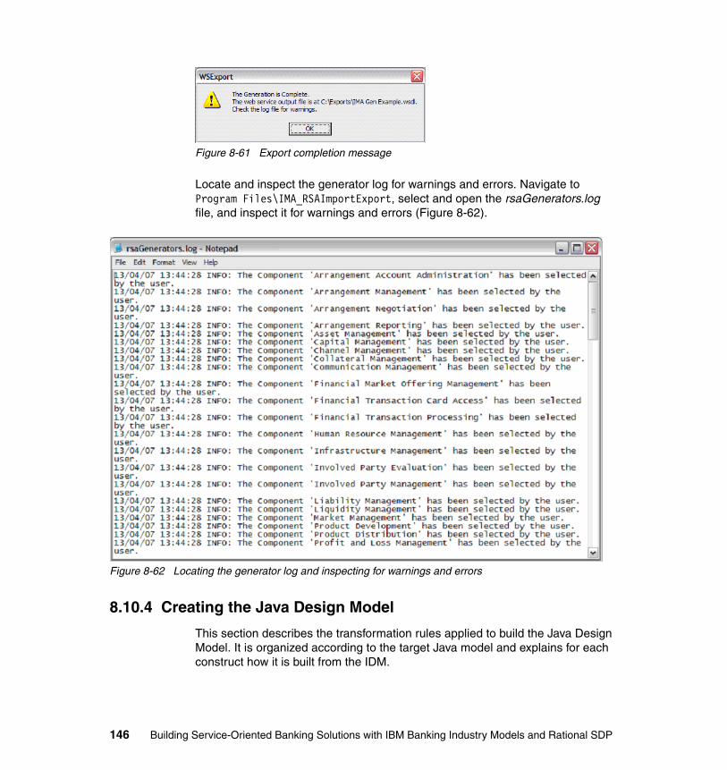
Figure 8-61 Export completion message
Locate and inspect the generator log for warnings and errors. Navigate to Program Files\IMA_RSAImportExport, select and open the rsaGenerators.log file, and inspect it for warnings and errors (Figure 8-62).
Figure 8-62 Locating the generator log and inspecting for warnings and errors
8.10.4 Creating the Java Design Model
This section describes the transformation rules applied to build the Java Design Model. It is organized according to the target Java model and explains for each construct how it is built from the IDM.
146 Building Service-Oriented Banking Solutions with IBM Banking Industry Models and Rational SDP
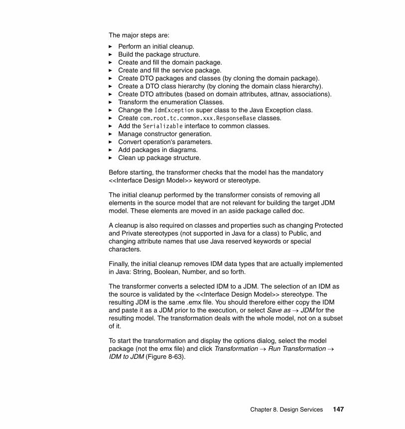
The major steps are:
� Perform an initial cleanup. � Build the package structure.� Create and fill the domain package. � Create and fill the service package. � Create DTO packages and classes (by cloning the domain package). � Create a DTO class hierarchy (by cloning the domain class hierarchy).� Create DTO attributes (based on domain attributes, attnav, associations). � Transform the enumeration Classes. � Change the IdmException super class to the Java Exception class. � Create com.root.tc.common.xxx.ResponseBase classes. � Add the Serializable interface to common classes. � Manage constructor generation. � Convert operation's parameters. � Add packages in diagrams. � Clean up package structure.
Before starting, the transformer checks that the model has the mandatory <<Interface Design Model>> keyword or stereotype.
The initial cleanup performed by the transformer consists of removing all elements in the source model that are not relevant for building the target JDM model. These elements are moved in an aside package called doc.
A cleanup is also required on classes and properties such as changing Protected and Private stereotypes (not supported in Java for a class) to Public, and changing attribute names that use Java reserved keywords or special characters.
Finally, the initial cleanup removes IDM data types that are actually implemented in Java: String, Boolean, Number, and so forth.
The transformer converts a selected IDM to a JDM. The selection of an IDM as the source is validated by the <<Interface Design Model>> stereotype. The resulting JDM is the same .emx file. You should therefore either copy the IDM and paste it as a JDM prior to the execution, or select Save as → JDM for the resulting model. The transformation deals with the whole model, not on a subset of it.
To start the transformation and display the options dialog, select the model package (not the emx file) and click Transformation → Run Transformation → IDM to JDM (Figure 8-63).
Chapter 8. Design Services 147
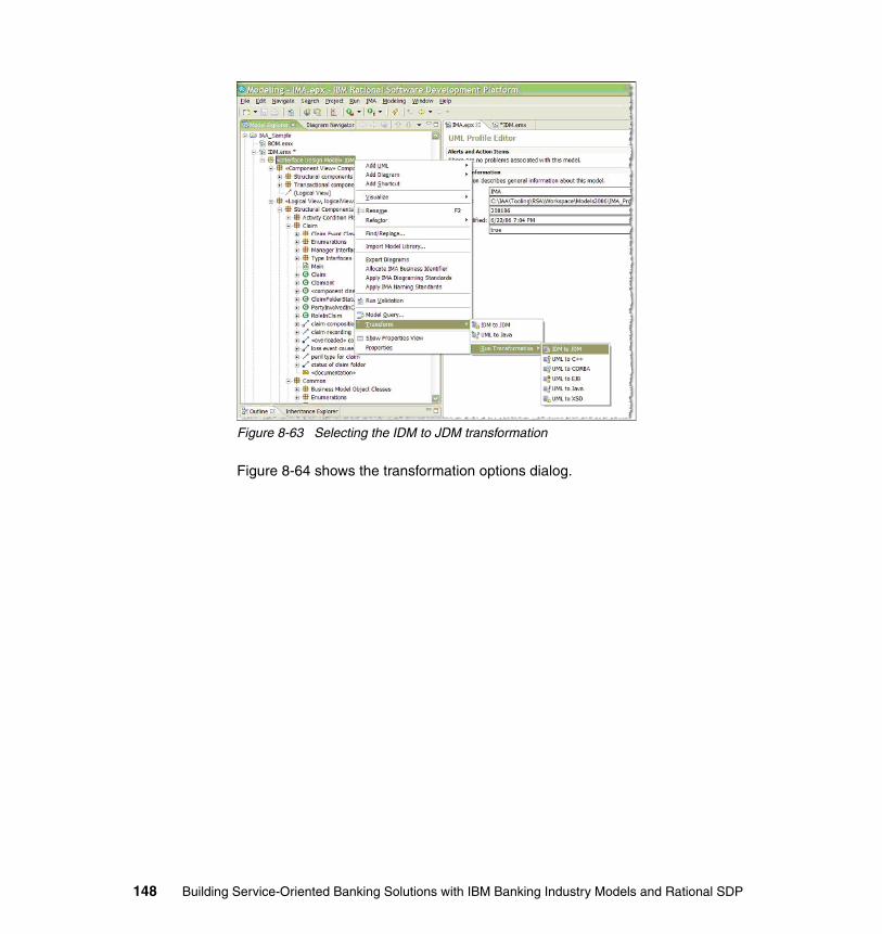
Figure 8-63 Selecting the IDM to JDM transformation
Figure 8-64 shows the transformation options dialog.
148 Building Service-Oriented Banking Solutions with IBM Banking Industry Models and Rational SDP
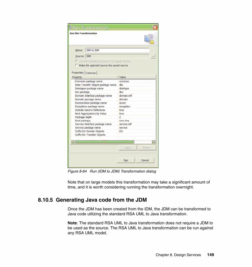
Figure 8-64 Run (IDM to JDM) Transformation dialog
Note that on large models this transformation may take a significant amount of time, and it is worth considering running the transformation overnight.
8.10.5 Generating Java code from the JDM
Once the JDM has been created from the IDM, the JDM can be transformed to Java code utilizing the standard RSA UML to Java transformation.
Note: The standard RSA UML to Java transformation does not require a JDM to be used as the source. The RSA UML to Java transformation can be run against any RSA UML model.
Chapter 8. Design Services 149
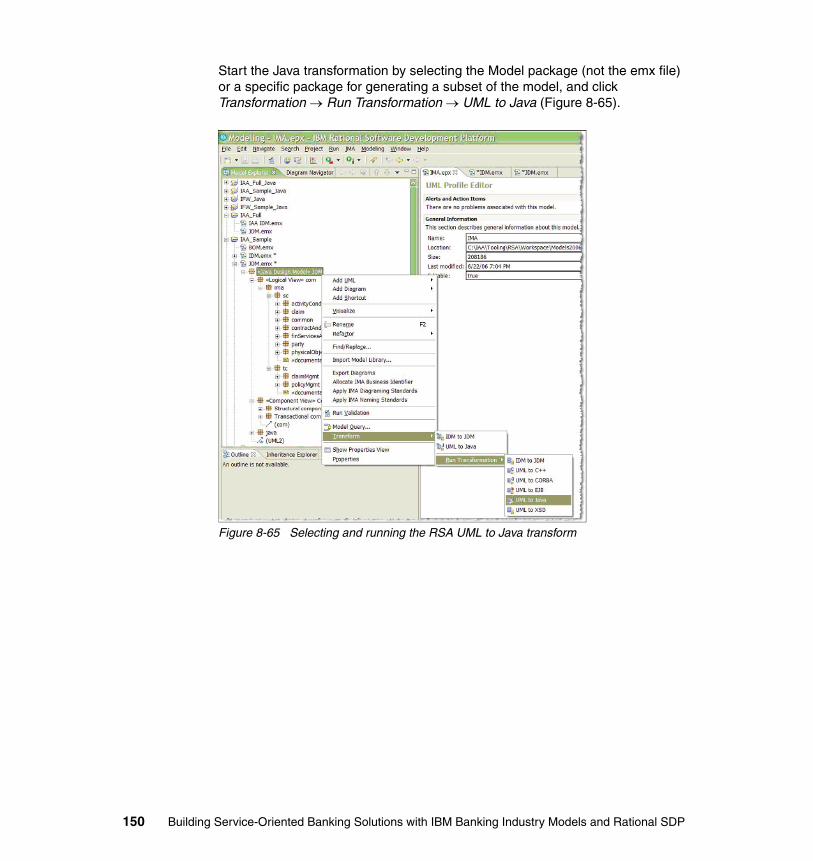
Start the Java transformation by selecting the Model package (not the emx file) or a specific package for generating a subset of the model, and click Transformation → Run Transformation → UML to Java (Figure 8-65).
Figure 8-65 Selecting and running the RSA UML to Java transform
150 Building Service-Oriented Banking Solutions with IBM Banking Industry Models and Rational SDP
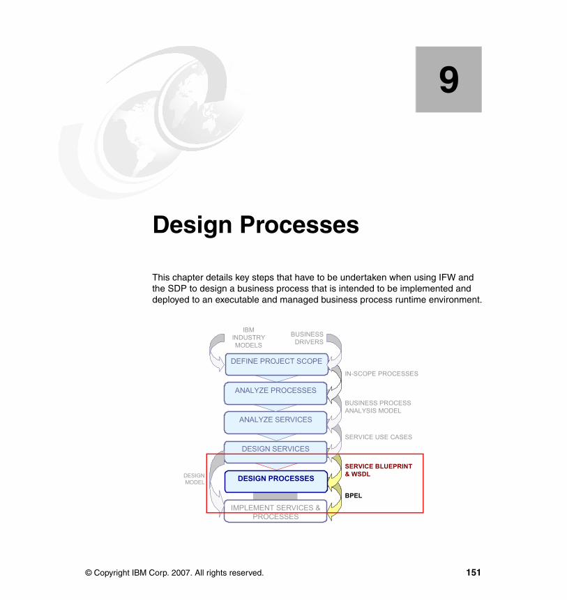
Chapter 9. Design Processes
This chapter details key steps that have to be undertaken when using IFW and the SDP to design a business process that is intended to be implemented and deployed to an executable and managed business process runtime environment.
9
DEFINE PROJECT SCOPE
ANALYZE SERVICES
DESIGN SERVICES
DESIGN PROCESSES
IMPLEMENT SERVICES & PROCESSES
ANALYZE PROCESSES
IN-SCOPE PROCESSES
BUSINESS PROCESS ANALYSIS MODEL
SERVICE BLUEPRINT& WSDL
BPEL
SERVICE USE CASES
DESIGNMODEL
IBMINDUSTRYMODELS
BUSINESSDRIVERS
© Copyright IBM Corp. 2007. All rights reserved. 151
9.1 Introduction to Design Processes1
An increasing number of organizations are implementing executable and managed business process workflows. Also known in the industry as managed workflows or orchestrated workflows, this is when a business process is deployed to a runtime environment that manages the execution of the business process via monitoring business events associated with business process's task execution. Managed workflows provide the basis for, and are a key part of, a business performance management. For example, if the Provide Loan Arrangement Offer process workflow was implemented and deployed as a managed workflow, the execution of the each of the workflow tasks would be managed and monitored. When a business task is finished executing, the next task is executed according to the business workflow control logic.
Process design, in general, refines the business process analysis model using the service design model and compromises that must be made for the targeted process runtime platform. This process design section details key steps that need to be undertaken when using IFW and the SDP to design a business process that is intended to be implemented and deployed to an executable and managed business process runtime environment.
9.2 Using IBM Rational SDP to Design Processes
We previously used WebSphere Business Modeler (WBM) to model, analyze, and optionally simulate analysis-level business processes. In this chapter we use WBM to refine the business process analysis model—designing processes to be deployed to WebSphere Process Server, by utilizing WBM’s ability to export models to the WebSphere Integration Developer (WID) process implementation tooling by generating Business Process Execution Language (BPEL).
Specifically, in this Design Processes chapter we use the WebSphere Business Modeler (WBM) component of the IBM Rational SDP to:
� Select within the business process analysis model the process targeted for design—Provide Loan Arrangement Offer—for the purpose of implementation and deployment to WebSphere Process Server.
� Isolate the target business process by exporting it and the process analysis model elements upon which it depends into a separate process design WBM modeling project.
1 Notes: 1) Additional methodological guidance/motivation is available in the IM&A Model Customization Roadmap. 2) Detailed IM&A modeling guidelines for WBM and RSx are available in the IM&A Process and Service Models Metamodel Guide and other related publications. These publications are available to licensees of the IBM Industry Models. Send an e-mail to [email protected] to ask for access.
152 Building Service-Oriented Banking Solutions with IBM Banking Industry Models and Rational SDP
� Refine the process-service boundary by, essentially, flattening the target process by converting all the (sub-)processes into tasks.
� Create detailed data type definitions utilizing the XSD created and exported during the Design Services activity.
� Refine the process flow control logic so that process can be transformed into an executable process flow including utilization of the detailed data type definitions.
9.3 Construct process design project
Processes can contain other processes. Contained processes are often referred to, within the context of the containing process, as sub-processes. Contained processes can, in turn, contain other processes, and so forth.
During process design we must consider what parts of the process analysis model we want to automate, and in what way. For example, it may be good design to automate the end-to-end process of Provide Loan Arrangement Offer using a BPEL flow. However, the sub processes within this flow may themselves be best implemented using business services. These services may be designed as Java implementations, for example, or they may be simply wrappers around existing services in existing applications.
Thus, when designing a process that is to be implemented and deployed as a managed workflow, it is often desirable to design and implement just the targeted process—and not all of its contained sub-processes—as a managed workflow. This can be accomplished by converting the targeted process’s sub-processes to tasks and then exporting only the targeted process and elements upon which it depends so it can be designed and implemented in isolation from the rest of the business process model.
Note that we do not recommend this exporting or splitting of the business process model during process analysis (Analyze Processes) time, as this would negate the benefits of having an enterprise model (benefits including, for example, access to re-usable analysis process elements defined elsewhere in the Enterprise Business (Process) Analysis model). The reason that this is recommended when designing processes is because we are no longer dealing with enterprise analysis (during which all re-use opportunities were identified, analyzed, validated, and realized in the preceding activities).
The first step in designing a process following the approach described above is to identify the subset of processes that are relevant to the solution. Specifically, these are the processes that are to be designed and implemented as managed
Chapter 9. Design Processes 153
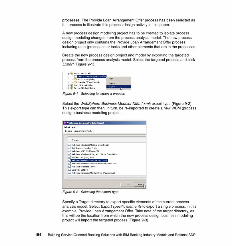
processes. The Provide Loan Arrangement Offer process has been selected as the process to illustrate this process design activity in this paper.
A new process design modeling project has to be created to isolate process design modeling changes from the process analysis model. The new process design project only contains the Provide Loan Arrangement Offer process, including (sub-)processes or tasks and other elements that are in the processes.
Create the new process design project and model by exporting the targeted process from the process analysis model. Select the targeted process and click Export (Figure 9-1).
Figure 9-1 Selecting to export a process
Select the WebSphere Business Modeler XML (.xml) export type (Figure 9-2). This export type can then, in turn, be re-imported to create a new WBM (process design) business modeling project.
Figure 9-2 Selecting the export type
Specify a Target directory to export specific elements of the current process analysis model. Select Export specific elements to export a single process, in this example, Provide Loan Arrangement Offer. Take note of the target directory, as this will be the location from which the new process design business modeling project will import the targeted process (Figure 9-3).
154 Building Service-Oriented Banking Solutions with IBM Banking Industry Models and Rational SDP
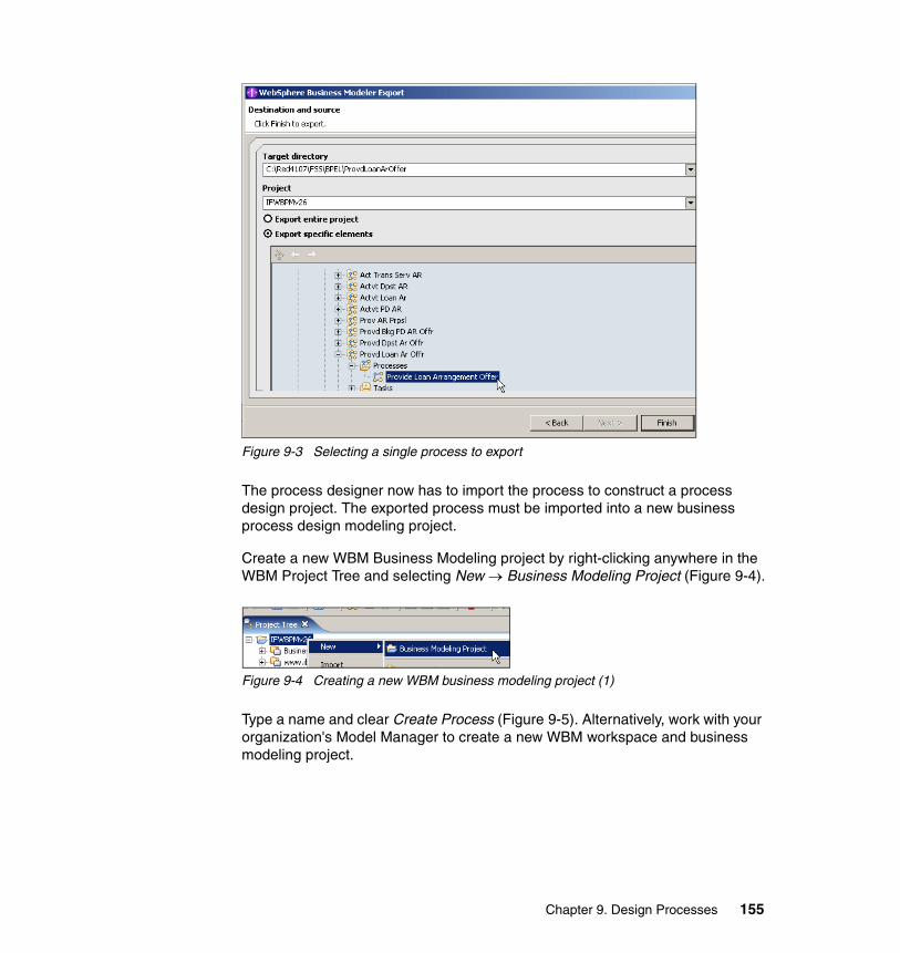
Figure 9-3 Selecting a single process to export
The process designer now has to import the process to construct a process design project. The exported process must be imported into a new business process design modeling project.
Create a new WBM Business Modeling project by right-clicking anywhere in the WBM Project Tree and selecting New → Business Modeling Project (Figure 9-4).
Figure 9-4 Creating a new WBM business modeling project (1)
Type a name and clear Create Process (Figure 9-5). Alternatively, work with your organization's Model Manager to create a new WBM workspace and business modeling project.
Chapter 9. Design Processes 155
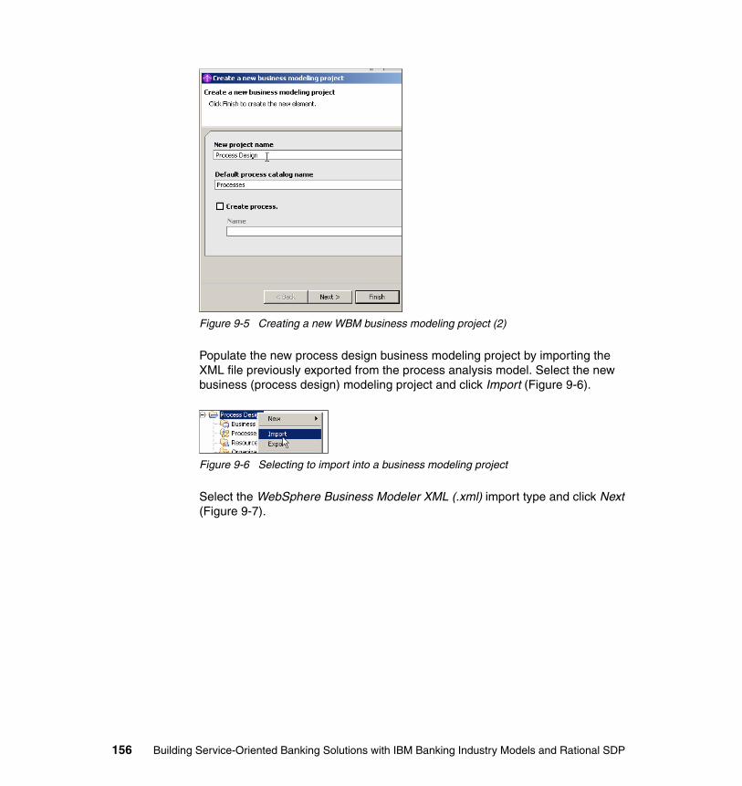
Figure 9-5 Creating a new WBM business modeling project (2)
Populate the new process design business modeling project by importing the XML file previously exported from the process analysis model. Select the new business (process design) modeling project and click Import (Figure 9-6).
Figure 9-6 Selecting to import into a business modeling project
Select the WebSphere Business Modeler XML (.xml) import type and click Next (Figure 9-7).
156 Building Service-Oriented Banking Solutions with IBM Banking Industry Models and Rational SDP
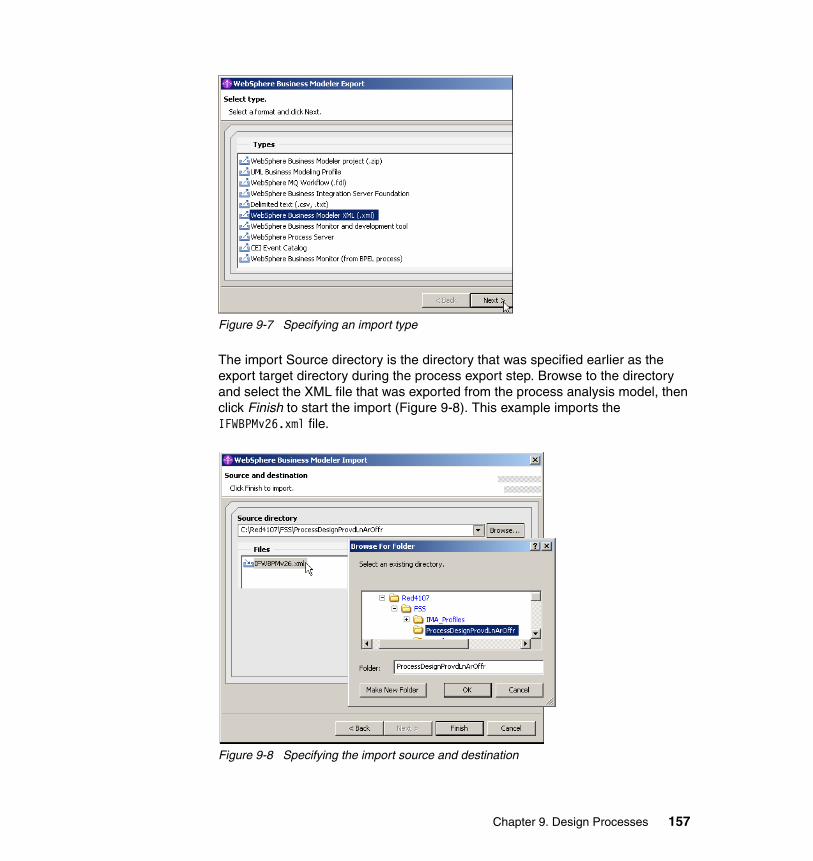
Figure 9-7 Specifying an import type
The import Source directory is the directory that was specified earlier as the export target directory during the process export step. Browse to the directory and select the XML file that was exported from the process analysis model, then click Finish to start the import (Figure 9-8). This example imports the IFWBPMv26.xml file.
Figure 9-8 Specifying the import source and destination
Chapter 9. Design Processes 157

Confirm the results of the import by navigating to and opening the Provide Loan Arrangement Offer process: Expand the business modeling project and navigate its folder structure. Note that there are other process elements, including global (sub-)processes and tasks, in addition to the Provide Loan Arrangement Offer in the project. This is because the exported version of Provide Loan Arrangement Offer uses these other process elements (Figure 9-9).
Figure 9-9 Navigating to and opening the process targeted for process design
9.4 Refine process-service boundary
The process design project created above includes (sub-)processes that we may not want to include in our process design project. This could be because many of these (sub-)processes are implemented by services outside of the BPEL environment. The way to exclude (sub-)processes from process design is to convert them in this process design model to tasks. This section illustrates the basic steps to convert a (sub-)process to a task.
Create a new task to replace a (sub-)process within the target process. This example replaces the Retrieve Full Customer Details (sub-)process. Click Create Local Task (icon), then click next to the (sub-)process that will be replaced in the Provide Loan Arrangement Offer process diagram (Figure 9-10).
Figure 9-10 Creating a local task to replace a (sub-)process
158 Building Service-Oriented Banking Solutions with IBM Banking Industry Models and Rational SDP
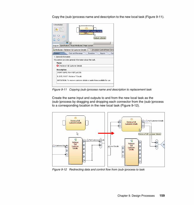
Copy the (sub-)process name and description to the new local task (Figure 9-11).
Figure 9-11 Copying (sub-)process name and description to replacement task
Create the same input and outputs to and from the new local task as the (sub-)process by dragging and dropping each connector from the (sub-)process to a corresponding location in the new local task (Figure 9-12).
Figure 9-12 Redirecting data and control flow from (sub-)process to task
Chapter 9. Design Processes 159
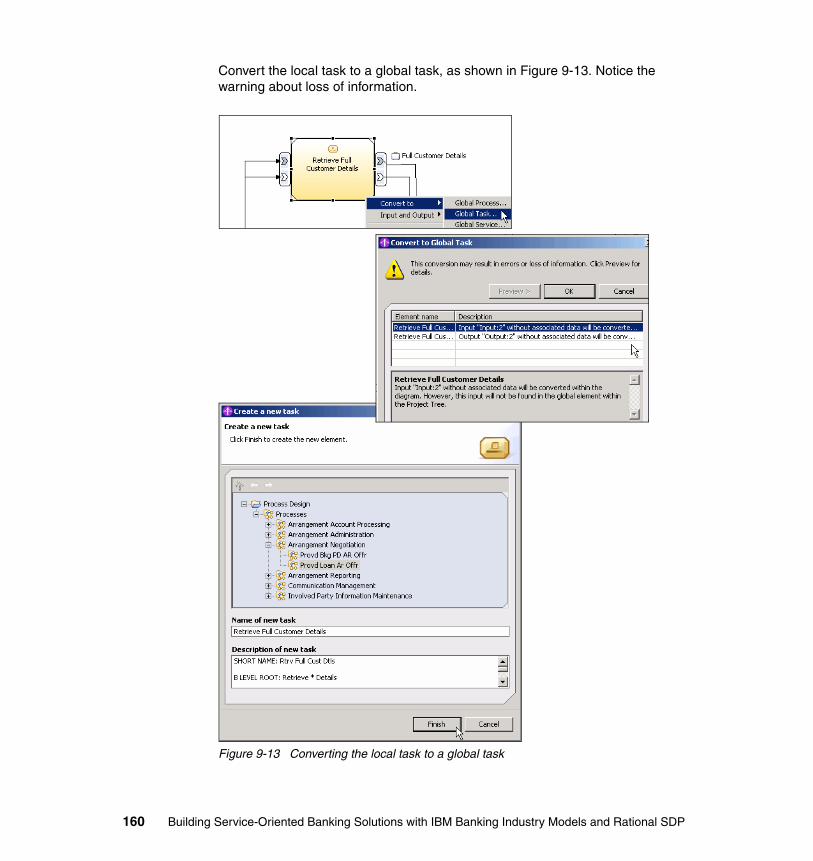
Convert the local task to a global task, as shown in Figure 9-13. Notice the warning about loss of information.
Figure 9-13 Converting the local task to a global task
160 Building Service-Oriented Banking Solutions with IBM Banking Industry Models and Rational SDP
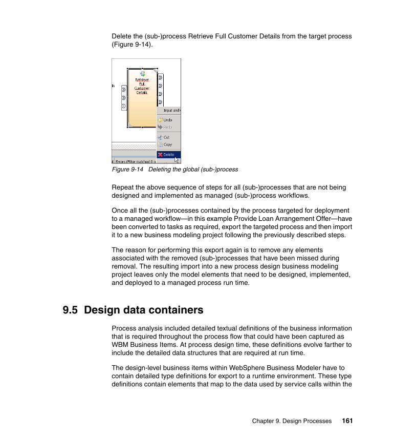
Delete the (sub-)process Retrieve Full Customer Details from the target process (Figure 9-14).
Figure 9-14 Deleting the global (sub-)process
Repeat the above sequence of steps for all (sub-)processes that are not being designed and implemented as managed (sub-)process workflows.
Once all the (sub-)processes contained by the process targeted for deployment to a managed workflow—in this example Provide Loan Arrangement Offer—have been converted to tasks as required, export the targeted process and then import it to a new business modeling project following the previously described steps.
The reason for performing this export again is to remove any elements associated with the removed (sub-)processes that have been missed during removal. The resulting import into a new process design business modeling project leaves only the model elements that need to be designed, implemented, and deployed to a managed process run time.
9.5 Design data containers
Process analysis included detailed textual definitions of the business information that is required throughout the process flow that could have been captured as WBM Business Items. At process design time, these definitions evolve farther to include the detailed data structures that are required at run time.
The design-level business items within WebSphere Business Modeler have to contain detailed type definitions for export to a runtime environment. These type definitions contain elements that map to the data used by service calls within the
Chapter 9. Design Processes 161
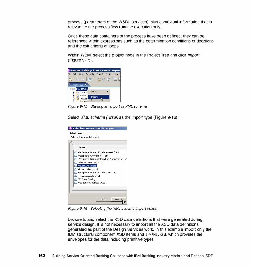
process (parameters of the WSDL services), plus contextual information that is relevant to the process flow runtime execution only.
Once these data containers of the process have been defined, they can be referenced within expressions such as the determination conditions of decisions and the exit criteria of loops.
Within WBM, select the project node in the Project Tree and click Import (Figure 9-15).
Figure 9-15 Starting an import of XML schema
Select XML schema (.wsdl) as the import type (Figure 9-16).
Figure 9-16 Selecting the XML schema import option
Browse to and select the XSD data definitions that were generated during service design. It is not necessary to import all the XSD data definitions generated as part of the Design Services work. In this example import only the IDM structural component XSD items and IFWXML.xsd, which provides the envelopes for the data including primitive types.
162 Building Service-Oriented Banking Solutions with IBM Banking Industry Models and Rational SDP
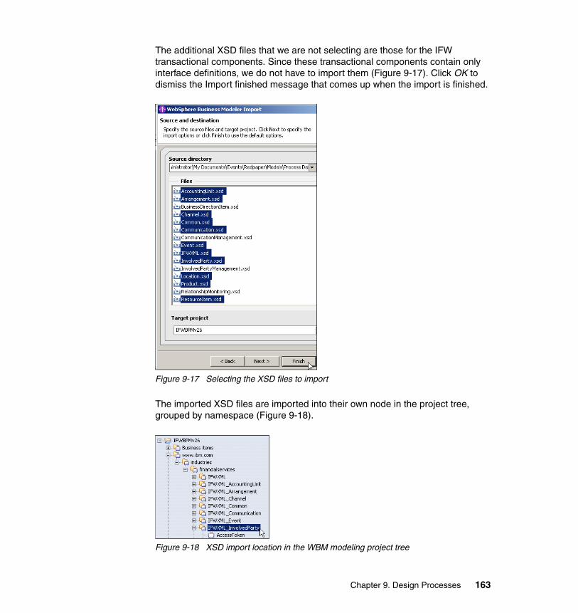
The additional XSD files that we are not selecting are those for the IFW transactional components. Since these transactional components contain only interface definitions, we do not have to import them (Figure 9-17). Click OK to dismiss the Import finished message that comes up when the import is finished.
Figure 9-17 Selecting the XSD files to import
The imported XSD files are imported into their own node in the project tree, grouped by namespace (Figure 9-18).
Figure 9-18 XSD import location in the WBM modeling project tree
Chapter 9. Design Processes 163

By reading the business item documentation from the analysis model we can determine the detailed data types that have to be included in each business item’s design definition. There are two mechanisms that can be used to do this:
� The addition of attributes to the business item� The derivation of the business items from a template.
Business item templates are created where XSD types are defined in the schema as being abstract. Otherwise business items are created.
This example updates the Full Customer Details business item. Select the business item and open the Business Item Editor. In the Documentation tab read the text (Figure 9-19).
Figure 9-19 Reviewing a business item’s description
The documentation specifies that Full Customer Details is defined as:
...Details of a customer, including all details of the underlying involved party…
164 Building Service-Oriented Banking Solutions with IBM Banking Industry Models and Rational SDP
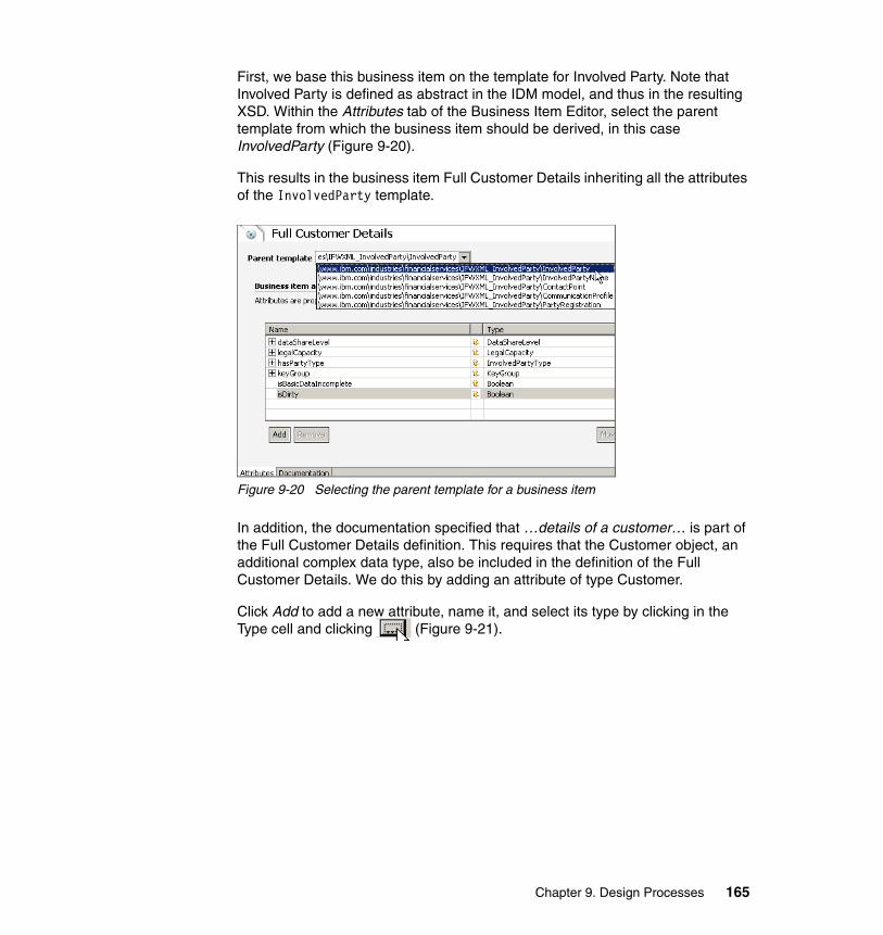
First, we base this business item on the template for Involved Party. Note that Involved Party is defined as abstract in the IDM model, and thus in the resulting XSD. Within the Attributes tab of the Business Item Editor, select the parent template from which the business item should be derived, in this case InvolvedParty (Figure 9-20).
This results in the business item Full Customer Details inheriting all the attributes of the InvolvedParty template.
Figure 9-20 Selecting the parent template for a business item
In addition, the documentation specified that …details of a customer… is part of the Full Customer Details definition. This requires that the Customer object, an additional complex data type, also be included in the definition of the Full Customer Details. We do this by adding an attribute of type Customer.
Click Add to add a new attribute, name it, and select its type by clicking in the Type cell and clicking (Figure 9-21).
Chapter 9. Design Processes 165
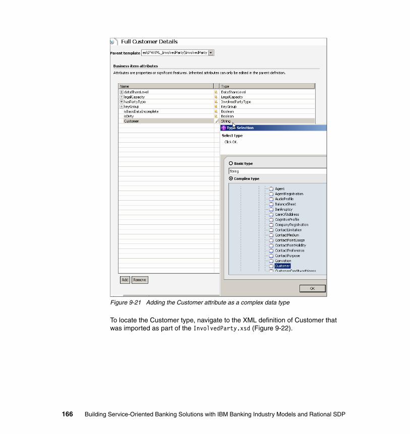
Figure 9-21 Adding the Customer attribute as a complex data type
To locate the Customer type, navigate to the XML definition of Customer that was imported as part of the InvolvedParty.xsd (Figure 9-22).
166 Building Service-Oriented Banking Solutions with IBM Banking Industry Models and Rational SDP
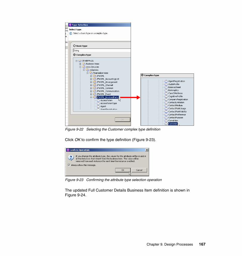
Figure 9-22 Selecting the Customer complex type definition
Click OK to confirm the type definition (Figure 9-23).
Figure 9-23 Confirming the attribute type selection operation
The updated Full Customer Details Business Item definition is shown in Figure 9-24.
Chapter 9. Design Processes 167
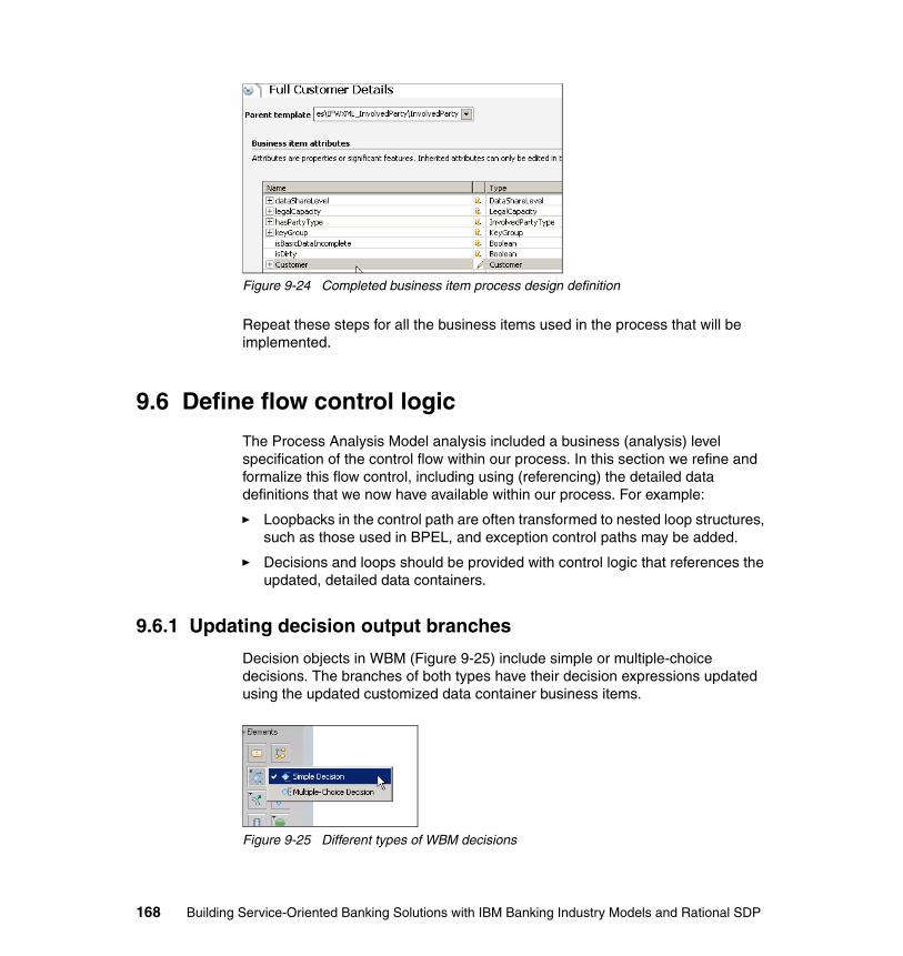
Figure 9-24 Completed business item process design definition
Repeat these steps for all the business items used in the process that will be implemented.
9.6 Define flow control logic
The Process Analysis Model analysis included a business (analysis) level specification of the control flow within our process. In this section we refine and formalize this flow control, including using (referencing) the detailed data definitions that we now have available within our process. For example:
� Loopbacks in the control path are often transformed to nested loop structures, such as those used in BPEL, and exception control paths may be added.
� Decisions and loops should be provided with control logic that references the updated, detailed data containers.
9.6.1 Updating decision output branches
Decision objects in WBM (Figure 9-25) include simple or multiple-choice decisions. The branches of both types have their decision expressions updated using the updated customized data container business items.
Figure 9-25 Different types of WBM decisions
168 Building Service-Oriented Banking Solutions with IBM Banking Industry Models and Rational SDP

Multiple-choice decisions allow multiple output branches. While only two output branches may be required when first modeling a process, selecting the multiple-choice decision type allows greater flexibility for more easily adding more decision output branches at a later time. Expressions must be explicitly created for each output branch. A simple decision object is limited to only two output branches, and after defining one decision the other is automatically created for you.
For illustration purposes we update the output branches of Decision 1 in the Provide Loan Arrangement Offer process.
One of the first things you may notice about a decision’s attributes on the General tab is an option to make the Decision object inclusive or exclusive. This attribute is used primarily for (optional) probability-type process simulation:
� Inclusive: All paths whose conditions are satisfied will be taken.� Exclusive: Only the first path whose condition is satisfied will be taken.
If you require an inclusive decision rather than an exclusive decision, select the decision and click Inclusive on the General tab in the Attributes view (Figure 9-26). Inclusive allows one or more output branches to be triggered/selected at the same time, thus enabling parallel processing. Refer to the WBM Help for more information about rules associated with this attribute and process simulation. For our example, leave the decision as Exclusive.
Chapter 9. Design Processes 169
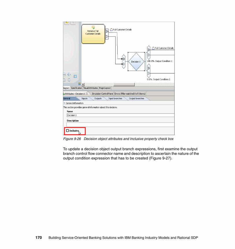
Figure 9-26 Decision object attributes and Inclusive property check box
To update a decision object output branch expressions, first examine the output branch control flow connector name and description to ascertain the nature of the output condition expression that has to be created (Figure 9-27).
170 Building Service-Oriented Banking Solutions with IBM Banking Industry Models and Rational SDP
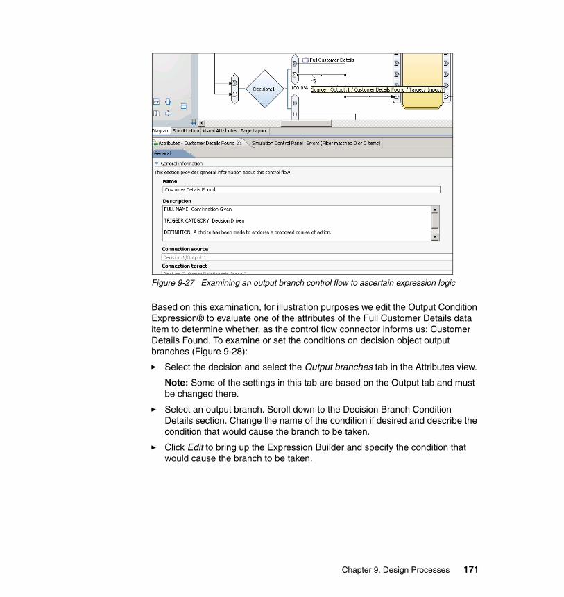
Figure 9-27 Examining an output branch control flow to ascertain expression logic
Based on this examination, for illustration purposes we edit the Output Condition Expression® to evaluate one of the attributes of the Full Customer Details data item to determine whether, as the control flow connector informs us: Customer Details Found. To examine or set the conditions on decision object output branches (Figure 9-28):
� Select the decision and select the Output branches tab in the Attributes view.
Note: Some of the settings in this tab are based on the Output tab and must be changed there.
� Select an output branch. Scroll down to the Decision Branch Condition Details section. Change the name of the condition if desired and describe the condition that would cause the branch to be taken.
� Click Edit to bring up the Expression Builder and specify the condition that would cause the branch to be taken.
Chapter 9. Design Processes 171

Figure 9-28 Selecting decision output branch output conditions to edit the expression
One way of assessing with a WBM expression whether Customer Details Found is true (this is the output condition specified in the model per the name and description of the output branch control flow connector) is to evaluate whether one of the attributes in the Full Customer Details business item does in fact exist or has an expected value.
To do this for our example, select Modeling artifact for the First term details within the Expression Builder dialog that was opened by clicking Edit, and then navigate and expand the First term details to the decision input that contains the data item Full Customer Details (Figure 9-29).
Figure 9-29 Navigating the Expression Builder modeling artifacts
172 Building Service-Oriented Banking Solutions with IBM Banking Industry Models and Rational SDP
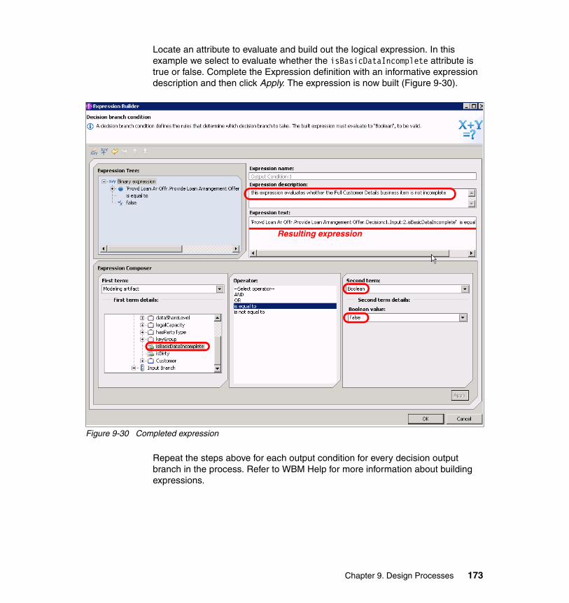
Locate an attribute to evaluate and build out the logical expression. In this example we select to evaluate whether the isBasicDataIncomplete attribute is true or false. Complete the Expression definition with an informative expression description and then click Apply. The expression is now built (Figure 9-30).
Figure 9-30 Completed expression
Repeat the steps above for each output condition for every decision output branch in the process. Refer to WBM Help for more information about building expressions.
Resulting expression
Chapter 9. Design Processes 173
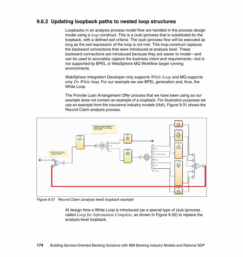
9.6.2 Updating loopback paths to nested loop structures
Loopbacks in an analysis process model flow are handled in the process design model using a loop construct. This is a (sub-)process that is substituted for the loopback, with a defined exit criteria. The (sub-)process flow will be executed as long as the exit expression of the loop is not met. This loop construct replaces the backward connections that were introduced at analysis level. These backward connections are introduced because they are easier to model—and can be used to accurately capture the business intent and requirements—but is not supported by BPEL or WebSphere MQ Workflow target running environments.
WebSphere Integration Developer only supports While Loop and MQ supports only Do While loop. For our example we use BPEL generation and, thus, the While Loop.
The Provide Loan Arrangement Offer process that we have been using as our example does not contain an example of a loopback. For illustration purposes we use an example from the insurance industry models (IAA). Figure 9-31 shows the Record Claim analysis process.
Figure 9-31 Record Claim (analysis level) loopback example
At design time a While Loop is introduced (as a special type of (sub-)process called Loop for Information Complete, as shown in Figure 9-32) to replace the analysis-level loopback.
174 Building Service-Oriented Banking Solutions with IBM Banking Industry Models and Rational SDP
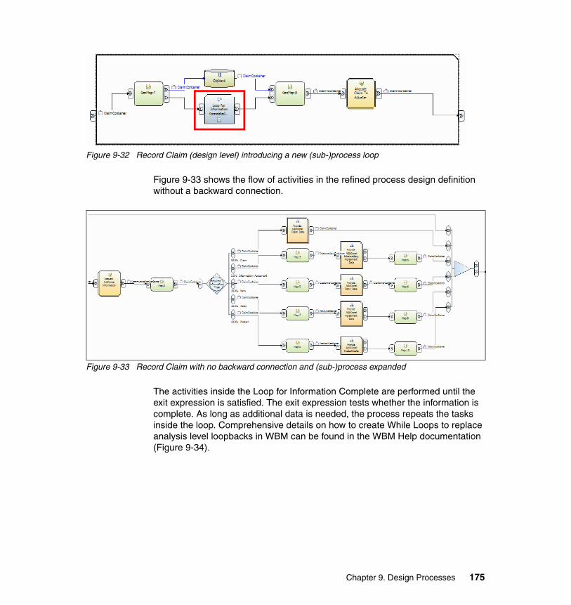
Figure 9-32 Record Claim (design level) introducing a new (sub-)process loop
Figure 9-33 shows the flow of activities in the refined process design definition without a backward connection.
Figure 9-33 Record Claim with no backward connection and (sub-)process expanded
The activities inside the Loop for Information Complete are performed until the exit expression is satisfied. The exit expression tests whether the information is complete. As long as additional data is needed, the process repeats the tasks inside the loop. Comprehensive details on how to create While Loops to replace analysis level loopbacks in WBM can be found in the WBM Help documentation (Figure 9-34).
Chapter 9. Design Processes 175
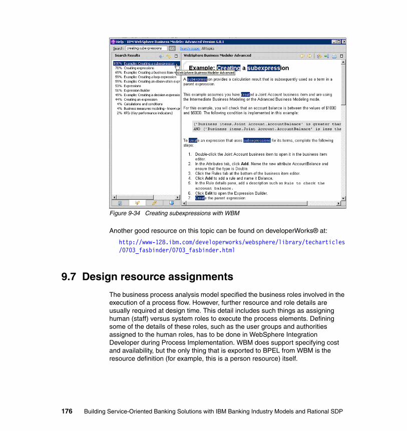
Figure 9-34 Creating subexpressions with WBM
Another good resource on this topic can be found on developerWorks® at:
http://www-128.ibm.com/developerworks/websphere/library/techarticles/0703_fasbinder/0703_fasbinder.html
9.7 Design resource assignments
The business process analysis model specified the business roles involved in the execution of a process flow. However, further resource and role details are usually required at design time. This detail includes such things as assigning human (staff) versus system roles to execute the process elements. Defining some of the details of these roles, such as the user groups and authorities assigned to the human roles, has to be done in WebSphere Integration Developer during Process Implementation. WBM does support specifying cost and availability, but the only thing that is exported to BPEL from WBM is the resource definition (for example, this is a person resource) itself.
176 Building Service-Oriented Banking Solutions with IBM Banking Industry Models and Rational SDP

To export an activity with role specifications, each role must be assigned to a BPEL supported resource definition. Refer to Table 9-1 (from WBM Help) for supported resource definition types. The net of what this table tells us is that WBM supports Person, Staff Resource definitions.
Table 9-1 Mapping elements to WebSphere Process Server table (from WBM Help)WebSphere Business
Modeler element
BPEL construct
WSDL/XSD construct
Comments
Resource definition, resource definition template
Not supported
Bulk resource Not supported
Bulk resource requirement
Not supported
Individual resource
Not supported
Individual resource
requirement
BPEL human task
Only individual resource requirements of Person or Staff or their subtypes are supported. If an individual resource is
assigned to a task or process and the associated resource definition is Person or Staff (or a subtype of these), during
the export, a human task with a potential owner is created. If you want to specify editor or reader instead of potential
owner, you must manually update the generated BPEL file. See Human task generation for information.
Role Not supported
Role requirement
BPEL human task
Only role requirements of Person or Staff or their subtypes are supported. If a role is assigned to a task or process and the associated resource definition is Person or Staff (or a subtype of these), during the export, a human task with a potential owner is created. If you want to specify editor or
reader instead of potential owner, you must manually update the generated BPEL file. See Human task generation
for information.
Service within a process
BPEL invoke
WSDL definition with a port
type
A WSDL definition is created for the service and a port type is created that represents the interface of the service. Each input criterion is transformed to a BPEL invoke activity and a corresponding WSDL operation. A BPEL partner link and
WSDL partner link type are created for the port type.
Service (exported alone rather than as
part of a process)
WSDL definition with a port
type
The port type represents the interface of the service.
Chapter 9. Design Processes 177
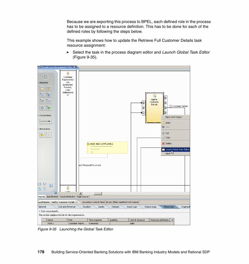
Because we are exporting this process to BPEL, each defined role in the process has to be assigned to a resource definition. This has to be done for each of the defined roles by following the steps below.
This example shows how to update the Retrieve Full Customer Details task resource assignment:
� Select the task in the process diagram editor and Launch Global Task Editor (Figure 9-35).
Figure 9-35 Launching the Global Task Editor
178 Building Service-Oriented Banking Solutions with IBM Banking Industry Models and Rational SDP
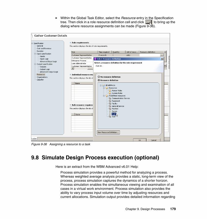
� Within the Global Task Editor, select the Resource entry in the Specification tree. Then click in a role resource definition cell and click to bring up the dialog where resource assignments can be made (Figure 9-36).
Figure 9-36 Assigning a resource to a task
9.8 Simulate Design Process execution (optional)
Here is an extract from the WBM Advanced v6.01 Help:
Process simulation provides a powerful method for analyzing a process. Whereas weighted average analysis provides a static, long-term view of the process, process simulation captures the dynamics of a shorter horizon. Process simulation enables the simultaneous viewing and examination of all cases in a virtual work environment. Process simulation also provides the ability to vary process input volume over time by adjusting resources and current allocations. Simulation output provides detailed information regarding
Chapter 9. Design Processes 179
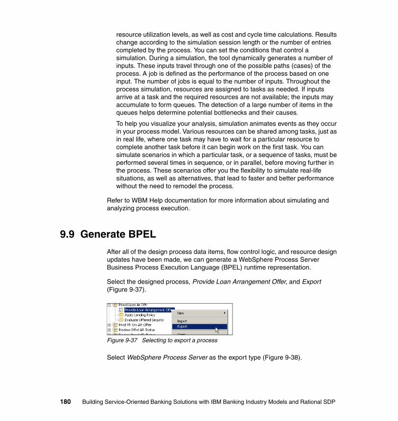
resource utilization levels, as well as cost and cycle time calculations. Results change according to the simulation session length or the number of entries completed by the process. You can set the conditions that control a simulation. During a simulation, the tool dynamically generates a number of inputs. These inputs travel through one of the possible paths (cases) of the process. A job is defined as the performance of the process based on one input. The number of jobs is equal to the number of inputs. Throughout the process simulation, resources are assigned to tasks as needed. If inputs arrive at a task and the required resources are not available; the inputs may accumulate to form queues. The detection of a large number of items in the queues helps determine potential bottlenecks and their causes.
To help you visualize your analysis, simulation animates events as they occur in your process model. Various resources can be shared among tasks, just as in real life, where one task may have to wait for a particular resource to complete another task before it can begin work on the first task. You can simulate scenarios in which a particular task, or a sequence of tasks, must be performed several times in sequence, or in parallel, before moving further in the process. These scenarios offer you the flexibility to simulate real-life situations, as well as alternatives, that lead to faster and better performance without the need to remodel the process.
Refer to WBM Help documentation for more information about simulating and analyzing process execution.
9.9 Generate BPEL
After all of the design process data items, flow control logic, and resource design updates have been made, we can generate a WebSphere Process Server Business Process Execution Language (BPEL) runtime representation.
Select the designed process, Provide Loan Arrangement Offer, and Export (Figure 9-37).
Figure 9-37 Selecting to export a process
Select WebSphere Process Server as the export type (Figure 9-38).
180 Building Service-Oriented Banking Solutions with IBM Banking Industry Models and Rational SDP
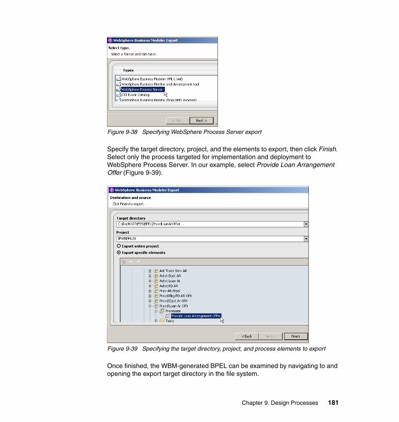
Figure 9-38 Specifying WebSphere Process Server export
Specify the target directory, project, and the elements to export, then click Finish. Select only the process targeted for implementation and deployment to WebSphere Process Server. In our example, select Provide Loan Arrangement Offer (Figure 9-39).
Figure 9-39 Specifying the target directory, project, and process elements to export
Once finished, the WBM-generated BPEL can be examined by navigating to and opening the export target directory in the file system.
Chapter 9. Design Processes 181
9.10 Transitioning to Implement Services and Processes
In this chapter we:
� Selected within the business process analysis model the process targeted for design—Provide Loan Arrangement Offer—for the purpose of implementation and deployment to WebSphere Process Server.
� Isolated the target business process by exporting it and the process analysis model elements upon which it depends into a separate process design WBM modeling project.
� Refined the process-service boundary by, essentially, flattening the target process by converting all the (sub-)processes into tasks.
� Created detailed data type definitions utilizing the XSD created and exported during the Design Services activity.
� Refined the process flow control logic so that the process can be transformed into an executable process flow including utilization of the detailed data type definitions.
The next set of activities in this solution development roadmap is to implement services and processes.
182 Building Service-Oriented Banking Solutions with IBM Banking Industry Models and Rational SDP

Chapter 10. Implement Services and Processes
Service and process implementation is the activity that takes the results of service and process design one step closer to solution delivery. While the details of these activities are not within the scope of this paper, it is important to acknowledge that these are the next set of activities in the creation of a service-oriented business solution.
10
DEFINE PROJECT SCOPE
ANALYZE SERVICES
DESIGN SERVICES
DESIGN PROCESSES
IMPLEMENT SERVICES & PROCESSES
ANALYZE PROCESSES
IN-SCOPE PROCESSES
BUSINESS PROCESS ANALYSIS MODEL
SERVICE BLUEPRINT& WSDL
BPEL
SERVICE USE CASES
DESIGNMODEL
IBMINDUSTRYMODELS
BUSINESSDRIVERS
© Copyright IBM Corp. 2007. All rights reserved. 183
Service implementation uses Rational Software Architect (RSA) to transform the software service design model, including the IFW Interface and Java Design Models (IDM and JDM), into a Java-based implementation. The design model is used to specify and accelerate this effort, including development of Java and J2EE components including Java classes that are used to implement core J2EE design patterns and constructs such as data transfer objects, session facades, and domain objects and to accelerate the development of J2EE components.
Process implementation uses the BPEL exported from the Process Design Model and the WSDL exported from Interface Design Model to implement a process to be deployed to a managed and monitored workflow runtime platform. This step is performed with WebSphere Integration Developer (WID).
184 Building Service-Oriented Banking Solutions with IBM Banking Industry Models and Rational SDP
Appendix A. Workstation configuration and software installation
In this appendix we describe the required workstation configuration and the installation procedure for the products of the IBM Rational Software Delivery Platform that are used in this Redpaper.
A
© Copyright IBM Corp. 2007. All rights reserved. 185
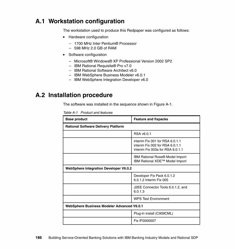
A.1 Workstation configurationThe workstation used to produce this Redpaper was configured as follows:
� Hardware configuration
– 1700 MHz Inter Pentium® Processor– 598 MHz 2.0 GB of RAM
� Software configuration
– Microsoft® Windows® XP Professional Version 2002 SP2– IBM Rational Requisite® Pro v7.0– IBM Rational Software Architect v6.0– IBM WebSphere Business Modeler v6.0.1– IBM WebSphere Integration Developer v6.0
A.2 Installation procedureThe software was installed in the sequence shown in Figure A-1.
Table A-1 Product and features
Base product Feature and fixpacks
Rational Software Delivery Platform
RSA v6.0.1
interim Fix 001 for RSA 6.0.1.1interim Fix 002 for RSA 6.0.1.1Interim Fix 003a for RSA 6.0.1.1
IBM Rational Rose® Model ImportIBM Rational XDE™ Model Import
WebSphere Integration Developer V6.0.2
Developer Fix Pack 6.0.1.26.0.1.2 Interim Fix 005
J2EE Connector Tools 6.0.1.2, and 6.0.1.3
WPS Test Environment
WebSphere Business Modeler Advanced V6.0.1
Plug-in install (C909CML)
Fix IF0000007
186 Building Service-Oriented Banking Solutions with IBM Banking Industry Models and Rational SDP
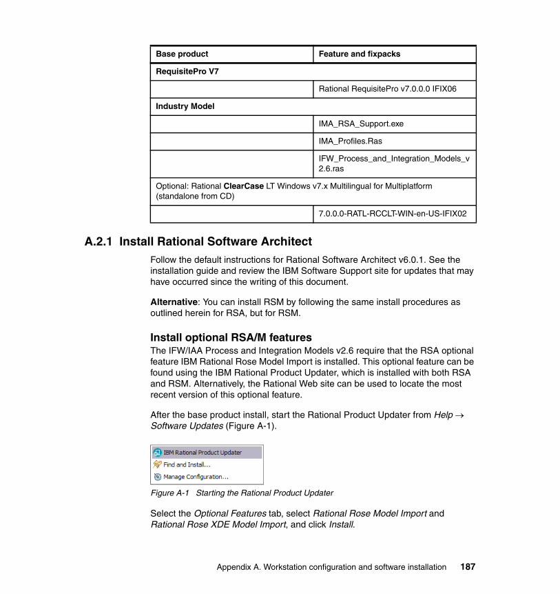
A.2.1 Install Rational Software Architect Follow the default instructions for Rational Software Architect v6.0.1. See the installation guide and review the IBM Software Support site for updates that may have occurred since the writing of this document.
Alternative: You can install RSM by following the same install procedures as outlined herein for RSA, but for RSM.
Install optional RSA/M featuresThe IFW/IAA Process and Integration Models v2.6 require that the RSA optional feature IBM Rational Rose Model Import is installed. This optional feature can be found using the IBM Rational Product Updater, which is installed with both RSA and RSM. Alternatively, the Rational Web site can be used to locate the most recent version of this optional feature.
After the base product install, start the Rational Product Updater from Help → Software Updates (Figure A-1).
Figure A-1 Starting the Rational Product Updater
Select the Optional Features tab, select Rational Rose Model Import and Rational Rose XDE Model Import, and click Install.
RequisitePro V7
Rational RequisitePro v7.0.0.0 IFIX06
Industry Model
IMA_RSA_Support.exe
IMA_Profiles.Ras
IFW_Process_and_Integration_Models_v2.6.ras
Optional: Rational ClearCase LT Windows v7.x Multilingual for Multiplatform (standalone from CD)
7.0.0.0-RATL-RCCLT-WIN-en-US-IFIX02
Base product Feature and fixpacks
Appendix A. Workstation configuration and software installation 187
Install RSA FixpacksWe recommend that all available updates to RSA be installed before opening the IFW/IAA, RSA/RSM Process and Integration Models v2.6, or running the IFW/IAA RSA/RSM Bridge.
From the Installed Products tab, select Find Updates, which displays the updates available for RSA. Minimally, select those fixes identified in the previous section.
Select the Updates tab to select the optional Rational Rose Model Import and Rational XDE Model Import features and click Install Updates.
If you are not returned to the Updates tab, select the Updates tab. Select the option to install the updates.
A.2.2 Install WebSphere Integration DeveloperFollow the default instructions for IBM WebSphere Integration Developer. See the installation guide and review the IBM Software Support site for updates that may have occurred since the writing of this document.
After the base product install, select Rational Product Updater and select the optional features tab. Select Rational Rose Model Import and Rational Rose XDE Model Import, and click Install.
Install WID fixpacksUsing the same process described in the “Install RSA Fixpacks” on page 188, select and install the WID fixes identified in “Installation procedure” on page 186.
When installing the WID fixpacks, for this Redpaper, we selected and installed WebSphere Integration Developer 6.0.1.2 Interim Fix 002.
Upon completion of the installation for RSA, WID, and their associated fixes, the Installed features should now appear as shown in Figure A-2.
188 Building Service-Oriented Banking Solutions with IBM Banking Industry Models and Rational SDP
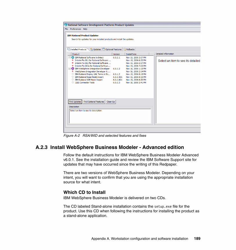
Figure A-2 RSA/WID and selected features and fixes
A.2.3 Install WebSphere Business Modeler - Advanced editionFollow the default instructions for IBM WebSphere Business Modeler Advanced v6.0.1. See the installation guide and review the IBM Software Support site for updates that may have occurred since the writing of this Redpaper.
There are two versions of WebSphere Business Modeler. Depending on your intent, you will want to confirm that you are using the appropriate installation source for what intent.
Which CD to InstallIBM WebSphere Business Modeler is delivered on two CDs.
The CD labeled Stand-alone installation contains the setup.exe file for the product. Use this CD when following the instructions for installing the product as a stand-alone application.
Appendix A. Workstation configuration and software installation 189
The CD labeled Plug-in installation contains the update site files for use with the Eclipse update manager. Use this CD when following the instructions for installing the product as plug-ins for WebSphere Integration Developer or any of the supported Rational products.
Run Modeler as a set of plug-ins for the supported Rational products.
Note: If you are running Modeler as a set of plug-ins for the supported Rational products, you must ensure that you do not use any of the Rational perspectives at the same time you have the business modeling perspective open. If you switch between the business modeling perspective and the Rational perspectives, it may cause problems with both the product and the model.
Install WBM fixpacksInstall fixpacks that are available using the Rational Product Updater and following the procedures described earlier.
A.2.4 Install Rational RequisitePro Follow the default instructions for IBM Rational RequisitePro v7.0. See the installation guide and review the IBM Software Support site for updates that may have occurred since the writing of this document.
A.2.5 Install industry models RSA support
Install and run IFW_RSA_support_v1.1.1.0.exe and follow the instructions at each installation step.
Note: You must be licensed to use the IBM Industry Models before you can access and install the IBM IM&A RSA utilities (including the IFW_RSA_support_v1.1.1.0.exe).
Send an e-mail to the IFW alias ([email protected]) to start the process of securing licensed access to the IBM IFW Industry Models. Licensed access to IBM Industry Models provides not only the model files, but also the IFW_RSA_support_v1.1.1.0.exe utility.
190 Building Service-Oriented Banking Solutions with IBM Banking Industry Models and Rational SDP
Appendix B. Modeling project setup and management
This appendix provides details on how to set up projects in each of the respective tools to support the usage model described in this Redpaper. All software and updates must be installed as described in Appendix A, “Workstation configuration and software installation” on page 185, prior to following any of the instructions in this appendix. A prerequisite to the software and installation is licensed access to IBM products (Industry Models and SDP).
This appendix also includes the specific steps required to:
� Export the IFW Process Models from their native RSA/M file format into WBM file format.
� Import the models into an existing WBM workspace.
� After customization of the IFW Process Models in WBM is complete, export the models from WBM.
� Import the models back into RSA/M native file format.
This set of procedures utilizes the RSA/M IMA Export and IMA Import utility that was installed when running the IFW_RSA_support_v1.1.1.0.exe (refer to A.2.5, “Install industry models RSA support” on page 190).
B
© Copyright IBM Corp. 2007. All rights reserved. 191

Projects like those described in this document also require management of changes to the models and other life cycle artifacts. RSA/M and RequisitePro as integrated parts of the IBM Rational SDP are also integrated with other SDP tooling supporting other parts of the SOA life cycle, including IBM Rational ClearCase and ClearQuest, the robust configuration and change management IBM product families. Governance and management of the industry models is detailed in another, soon to be published, paper (contact Nick Norris at [email protected] for the latest status of the Govern and Manage Industry Enterprise Models paper).
B.1 RequisitePro project setupThis section provides the steps to set up a new RequisitePro project to enable using RequisitePro as described in this paper. RequisitePro projects can be created from a blank project template or a pre-existing project template (a number of these are provided as part of the RequisitePro product install).
Note: The distribution mechanism for the RequisitePro IFW project template (used throughout this document) has not yet been established at the time of this document’s publication. If you would like a copy of this template you must first be an official licensee of the IFW models. Send an e-mail to [email protected] and [email protected]. We will first verify your IFW licensee status and then send you a copy of this RequisitePro project template.
At the time of this Redpaper's publication the IFW Rational SDP Redpaper RequisitePro project template contains:
� All the requirement record and document types, views, and project structure shown in the Redpaper
� A small subset of the IFW Financial Services Function Model as RequisitePro requirement records
� A subset of the IFW Process Model and BOM elements as RequisitePro requirement records
B.1.1 Create a RequisitePro projectStart RequisitePro by selecting Start → All Programs → IBM Rational → RequisitePro. In the Create Project window select the RequisitePro project template that you want to use to create your project. Figure B-1 shows creating a project from the IFW Rational SDP Redpaper RequisitePro project template.
192 Building Service-Oriented Banking Solutions with IBM Banking Industry Models and Rational SDP
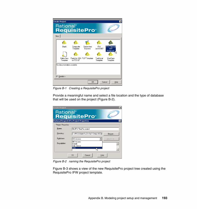
Figure B-1 Creating a RequisitePro project
Provide a meaningful name and select a file location and the type of database that will be used on the project (Figure B-2).
Figure B-2 naming the RequisitePro project
Figure B-3 shows a view of the new RequisitePro project tree created using the RequisitePro IFW project template.
Appendix B. Modeling project setup and management 193
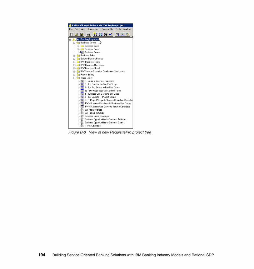
Figure B-3 View of new RequisitePro project tree
194 Building Service-Oriented Banking Solutions with IBM Banking Industry Models and Rational SDP
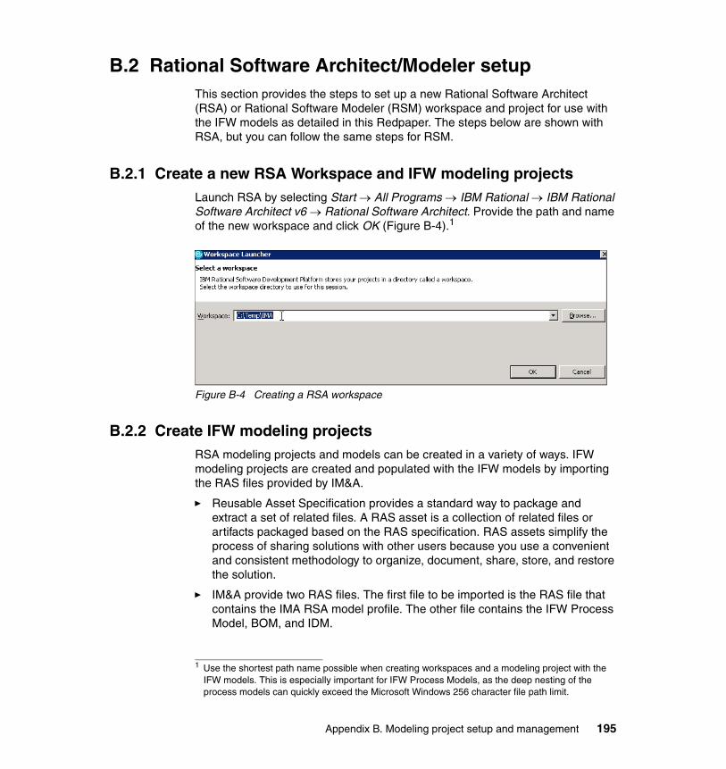
B.2 Rational Software Architect/Modeler setupThis section provides the steps to set up a new Rational Software Architect (RSA) or Rational Software Modeler (RSM) workspace and project for use with the IFW models as detailed in this Redpaper. The steps below are shown with RSA, but you can follow the same steps for RSM.
B.2.1 Create a new RSA Workspace and IFW modeling projectsLaunch RSA by selecting Start → All Programs → IBM Rational → IBM Rational Software Architect v6 → Rational Software Architect. Provide the path and name of the new workspace and click OK (Figure B-4).1
Figure B-4 Creating a RSA workspace
B.2.2 Create IFW modeling projectsRSA modeling projects and models can be created in a variety of ways. IFW modeling projects are created and populated with the IFW models by importing the RAS files provided by IM&A.
� Reusable Asset Specification provides a standard way to package and extract a set of related files. A RAS asset is a collection of related files or artifacts packaged based on the RAS specification. RAS assets simplify the process of sharing solutions with other users because you use a convenient and consistent methodology to organize, document, share, store, and restore the solution.
� IM&A provide two RAS files. The first file to be imported is the RAS file that contains the IMA RSA model profile. The other file contains the IFW Process Model, BOM, and IDM.
1 Use the shortest path name possible when creating workspaces and a modeling project with the IFW models. This is especially important for IFW Process Models, as the deep nesting of the process models can quickly exceed the Microsoft Windows 256 character file path limit.
Appendix B. Modeling project setup and management 195
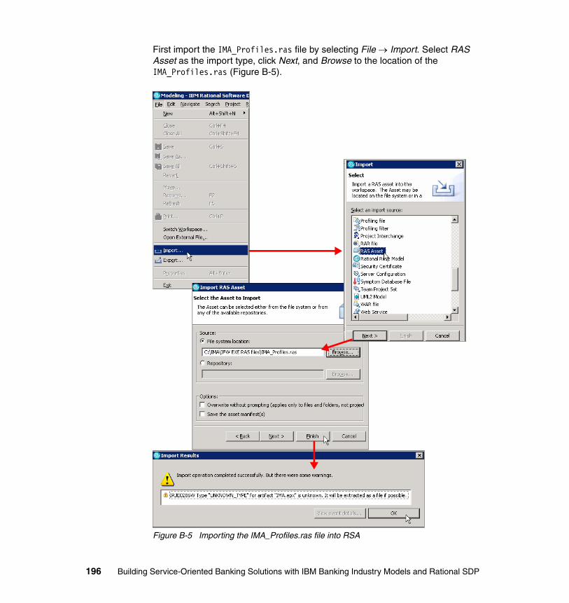
First import the IMA_Profiles.ras file by selecting File → Import. Select RAS Asset as the import type, click Next, and Browse to the location of the IMA_Profiles.ras (Figure B-5).
Figure B-5 Importing the IMA_Profiles.ras file into RSA
196 Building Service-Oriented Banking Solutions with IBM Banking Industry Models and Rational SDP
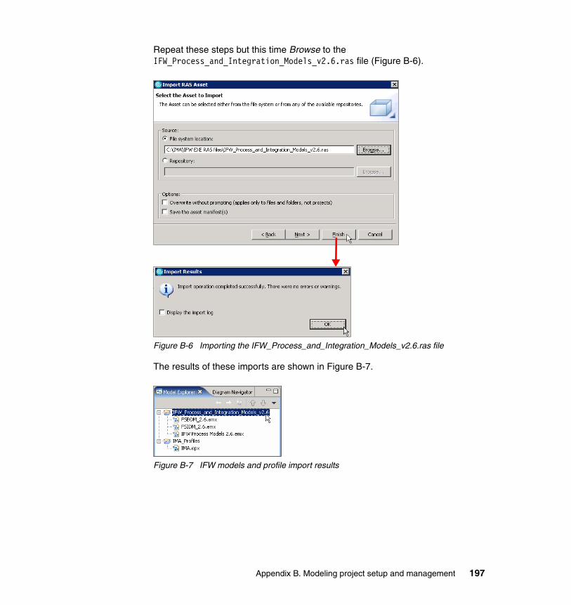
Repeat these steps but this time Browse to the IFW_Process_and_Integration_Models_v2.6.ras file (Figure B-6).
Figure B-6 Importing the IFW_Process_and_Integration_Models_v2.6.ras file
The results of these imports are shown in Figure B-7.
Figure B-7 IFW models and profile import results
Appendix B. Modeling project setup and management 197
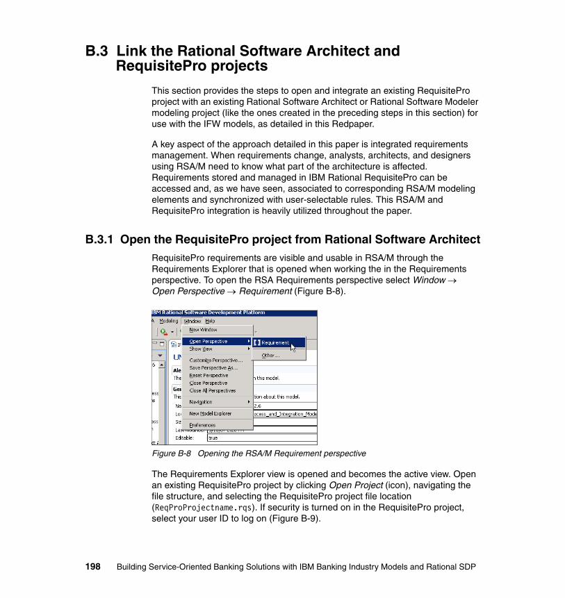
B.3 Link the Rational Software Architect and RequisitePro projects
This section provides the steps to open and integrate an existing RequisitePro project with an existing Rational Software Architect or Rational Software Modeler modeling project (like the ones created in the preceding steps in this section) for use with the IFW models, as detailed in this Redpaper.
A key aspect of the approach detailed in this paper is integrated requirements management. When requirements change, analysts, architects, and designers using RSA/M need to know what part of the architecture is affected. Requirements stored and managed in IBM Rational RequisitePro can be accessed and, as we have seen, associated to corresponding RSA/M modeling elements and synchronized with user-selectable rules. This RSA/M and RequisitePro integration is heavily utilized throughout the paper.
B.3.1 Open the RequisitePro project from Rational Software ArchitectRequisitePro requirements are visible and usable in RSA/M through the Requirements Explorer that is opened when working the in the Requirements perspective. To open the RSA Requirements perspective select Window → Open Perspective → Requirement (Figure B-8).
Figure B-8 Opening the RSA/M Requirement perspective
The Requirements Explorer view is opened and becomes the active view. Open an existing RequisitePro project by clicking Open Project (icon), navigating the file structure, and selecting the RequisitePro project file location (ReqProProjectname.rqs). If security is turned on in the RequisitePro project, select your user ID to log on (Figure B-9).
198 Building Service-Oriented Banking Solutions with IBM Banking Industry Models and Rational SDP
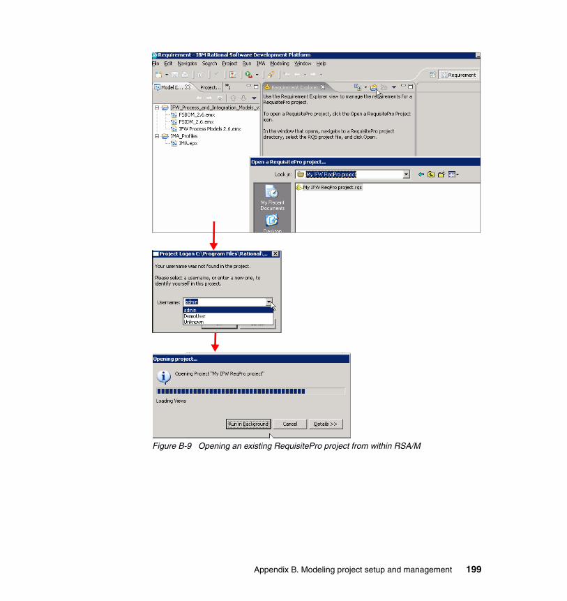
Figure B-9 Opening an existing RequisitePro project from within RSA/M
Appendix B. Modeling project setup and management 199
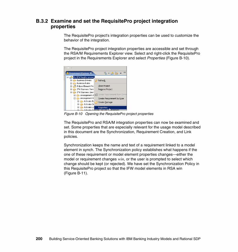
B.3.2 Examine and set the RequisitePro project integration properties
The RequisitePro project's integration properties can be used to customize the behavior of the integration.
The RequisitePro project integration properties are accessible and set through the RSA/M Requirements Explorer view. Select and right-click the RequisitePro project in the Requirements Explorer and select Properties (Figure B-10).
Figure B-10 Opening the RequisitePro project properties
The RequisitePro and RSA/M integration properties can now be examined and set. Some properties that are especially relevant for the usage model described in this document are the Synchronization, Requirement Creation, and Link policies.
Synchronization keeps the name and text of a requirement linked to a model element in synch. The Synchronization policy establishes what happens if the one of these requirement or model element properties changes—either the model or requirement changes win, or the user is prompted to select which change should be kept (or rejected). We have set the Synchronization Policy in this RequisitePro project so that the IFW model elements in RSA win (Figure B-11).
200 Building Service-Oriented Banking Solutions with IBM Banking Industry Models and Rational SDP
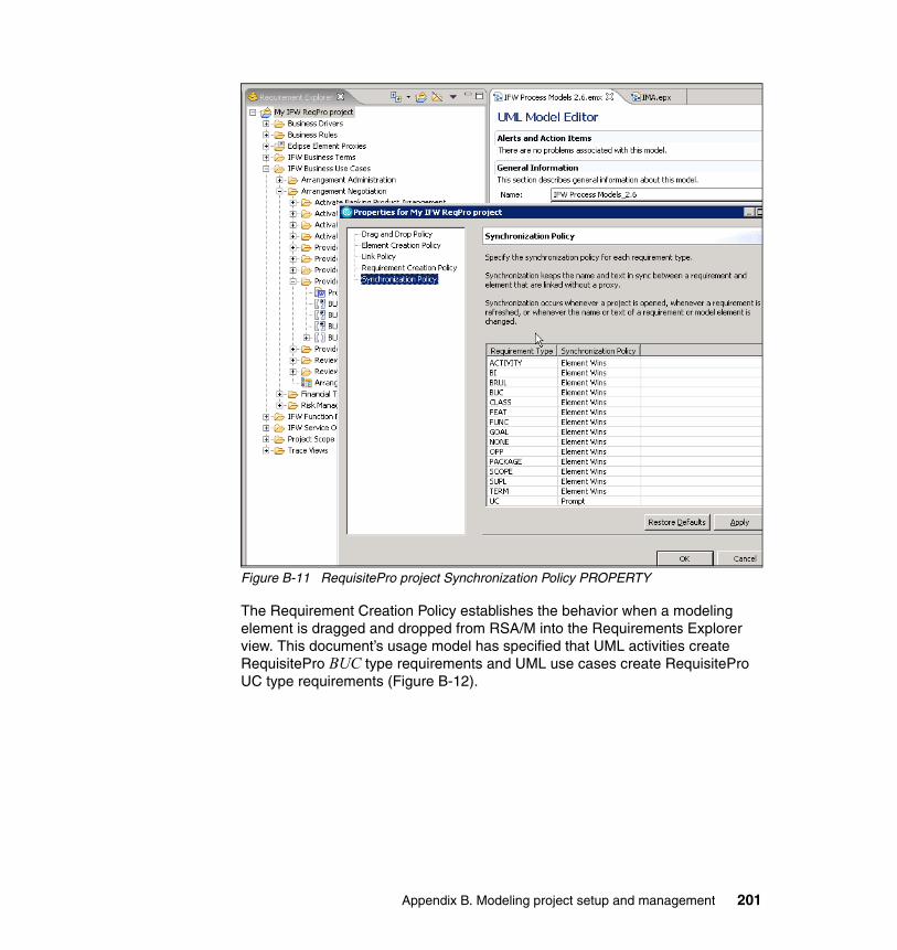
Figure B-11 RequisitePro project Synchronization Policy PROPERTY
The Requirement Creation Policy establishes the behavior when a modeling element is dragged and dropped from RSA/M into the Requirements Explorer view. This document’s usage model has specified that UML activities create RequisitePro BUC type requirements and UML use cases create RequisitePro UC type requirements (Figure B-12).
Appendix B. Modeling project setup and management 201
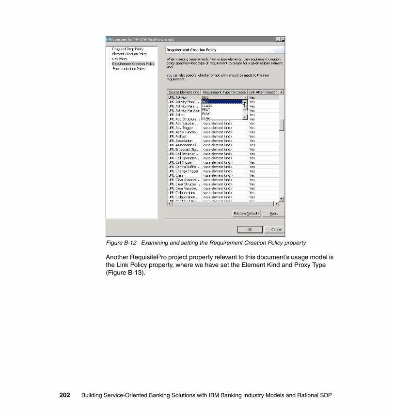
Figure B-12 Examining and setting the Requirement Creation Policy property
Another RequisitePro project property relevant to this document’s usage model is the Link Policy property, where we have set the Element Kind and Proxy Type (Figure B-13).
202 Building Service-Oriented Banking Solutions with IBM Banking Industry Models and Rational SDP
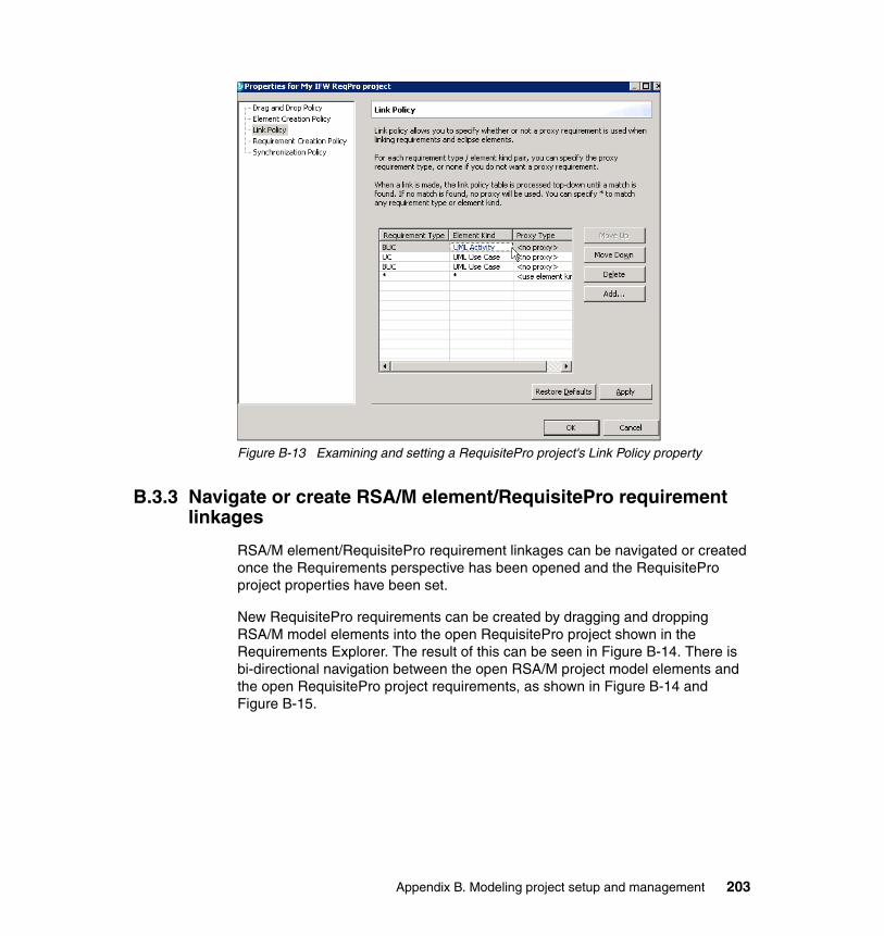
Figure B-13 Examining and setting a RequisitePro project's Link Policy property
B.3.3 Navigate or create RSA/M element/RequisitePro requirement linkages
RSA/M element/RequisitePro requirement linkages can be navigated or created once the Requirements perspective has been opened and the RequisitePro project properties have been set.
New RequisitePro requirements can be created by dragging and dropping RSA/M model elements into the open RequisitePro project shown in the Requirements Explorer. The result of this can be seen in Figure B-14. There is bi-directional navigation between the open RSA/M project model elements and the open RequisitePro project requirements, as shown in Figure B-14 and Figure B-15.
Appendix B. Modeling project setup and management 203

Figure B-14 Navigating from RSA/M model element to its linked RequisitePro requirement
204 Building Service-Oriented Banking Solutions with IBM Banking Industry Models and Rational SDP
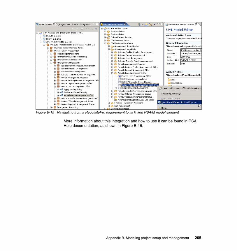
Figure B-15 Navigating from a RequisitePro requirement to its linked RSA/M model element
More information about this integration and how to use it can be found in RSA Help documentation, as shown in Figure B-16.
Appendix B. Modeling project setup and management 205
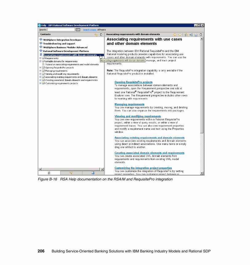
Figure B-16 RSA Help documentation on the RSA/M and RequisitePro integration
206 Building Service-Oriented Banking Solutions with IBM Banking Industry Models and Rational SDP
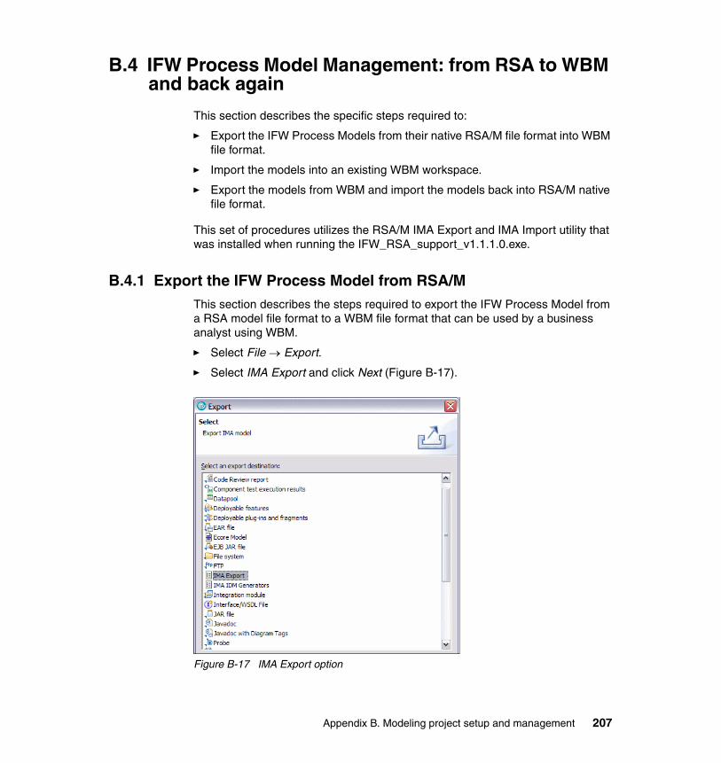
B.4 IFW Process Model Management: from RSA to WBM and back again
This section describes the specific steps required to:
� Export the IFW Process Models from their native RSA/M file format into WBM file format.
� Import the models into an existing WBM workspace.
� Export the models from WBM and import the models back into RSA/M native file format.
This set of procedures utilizes the RSA/M IMA Export and IMA Import utility that was installed when running the IFW_RSA_support_v1.1.1.0.exe.
B.4.1 Export the IFW Process Model from RSA/MThis section describes the steps required to export the IFW Process Model from a RSA model file format to a WBM file format that can be used by a business analyst using WBM.
� Select File → Export.
� Select IMA Export and click Next (Figure B-17).
Figure B-17 IMA Export option
Appendix B. Modeling project setup and management 207
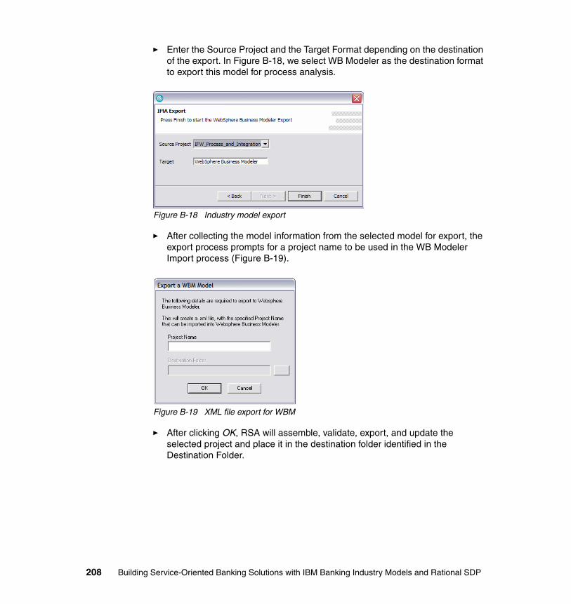
� Enter the Source Project and the Target Format depending on the destination of the export. In Figure B-18, we select WB Modeler as the destination format to export this model for process analysis.
Figure B-18 Industry model export
� After collecting the model information from the selected model for export, the export process prompts for a project name to be used in the WB Modeler Import process (Figure B-19).
Figure B-19 XML file export for WBM
� After clicking OK, RSA will assemble, validate, export, and update the selected project and place it in the destination folder identified in the Destination Folder.
208 Building Service-Oriented Banking Solutions with IBM Banking Industry Models and Rational SDP

B.4.2 Import IFW process models into WebSphere Business ModelerThe IFW Process Models are delivered and managed in RSA/M, preferably in conjunction with an Eclipse SCM compliant tool like IBM Rational Unified Change Management ClearCase and ClearQuest. WBM is the IBM process analysis tool for business stakeholders, and is used to edit the IFW Process Model. The IFW Process Model must be exported from RSA/M into a file format (XML) that WBM can import.
Creating a WBM projectCreate a WBM project using the New Project wizard:
� Select File → New Business Modeling Project (Figure B-20).
Figure B-20 Creating a Business Modeling Project
� Specify a name for the new WBM project. Clear Create Process and click Finish (Figure B-21).
Appendix B. Modeling project setup and management 209
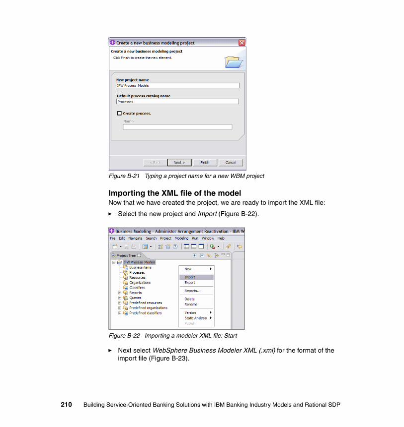
Figure B-21 Typing a project name for a new WBM project
Importing the XML file of the modelNow that we have created the project, we are ready to import the XML file:
� Select the new project and Import (Figure B-22).
Figure B-22 Importing a modeler XML file: Start
� Next select WebSphere Business Modeler XML (.xml) for the format of the import file (Figure B-23).
210 Building Service-Oriented Banking Solutions with IBM Banking Industry Models and Rational SDP
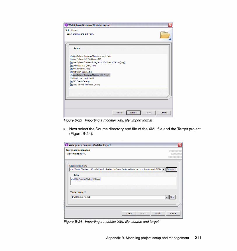
Figure B-23 Importing a modeler XML file: import format
� Next select the Source directory and file of the XML file and the Target project (Figure B-24).
Figure B-24 Importing a modeler XML file: source and target
Appendix B. Modeling project setup and management 211
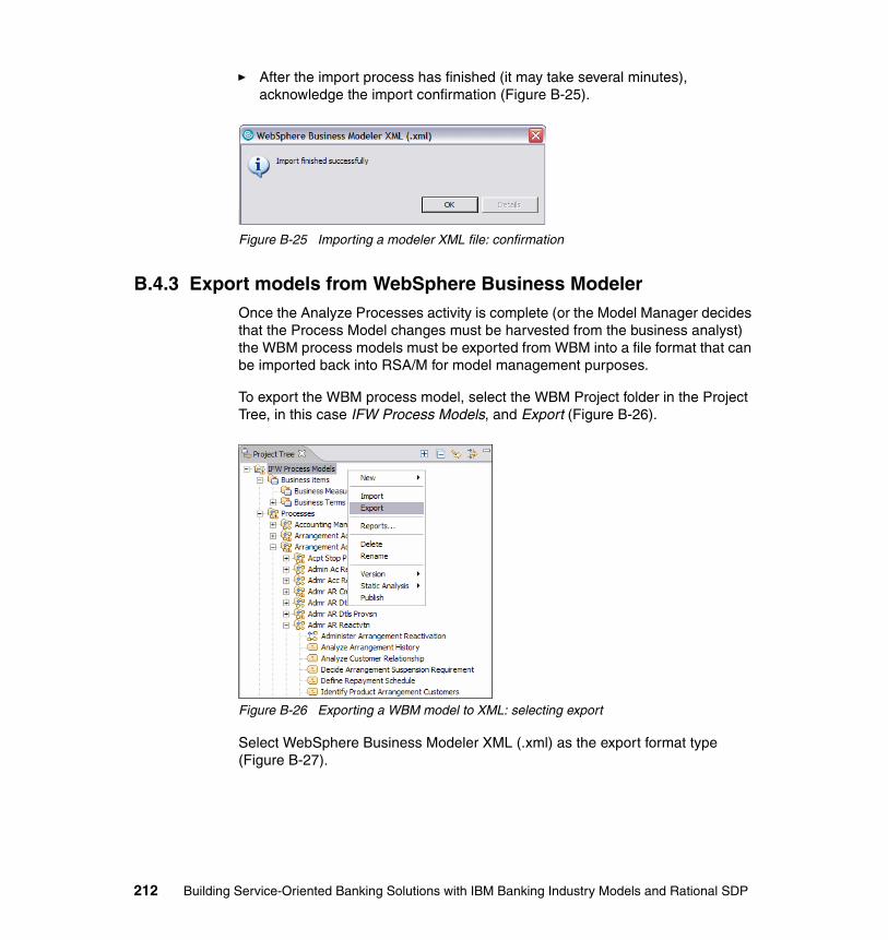
� After the import process has finished (it may take several minutes), acknowledge the import confirmation (Figure B-25).
Figure B-25 Importing a modeler XML file: confirmation
B.4.3 Export models from WebSphere Business ModelerOnce the Analyze Processes activity is complete (or the Model Manager decides that the Process Model changes must be harvested from the business analyst) the WBM process models must be exported from WBM into a file format that can be imported back into RSA/M for model management purposes.
To export the WBM process model, select the WBM Project folder in the Project Tree, in this case IFW Process Models, and Export (Figure B-26).
Figure B-26 Exporting a WBM model to XML: selecting export
Select WebSphere Business Modeler XML (.xml) as the export format type (Figure B-27).
212 Building Service-Oriented Banking Solutions with IBM Banking Industry Models and Rational SDP
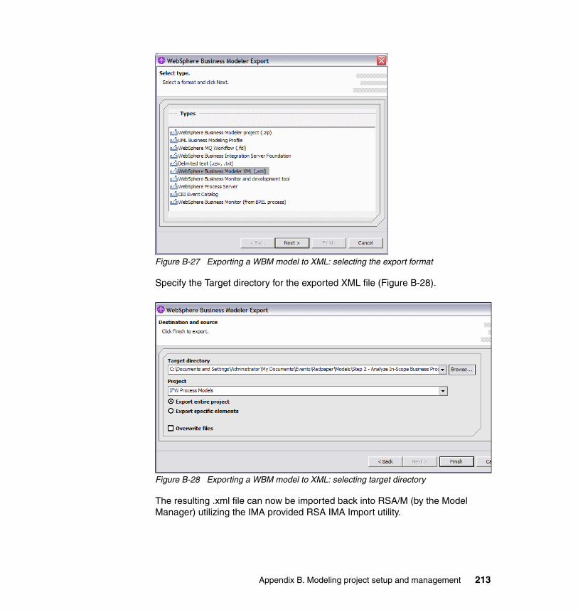
Figure B-27 Exporting a WBM model to XML: selecting the export format
Specify the Target directory for the exported XML file (Figure B-28).
Figure B-28 Exporting a WBM model to XML: selecting target directory
The resulting .xml file can now be imported back into RSA/M (by the Model Manager) utilizing the IMA provided RSA IMA Import utility.
Appendix B. Modeling project setup and management 213
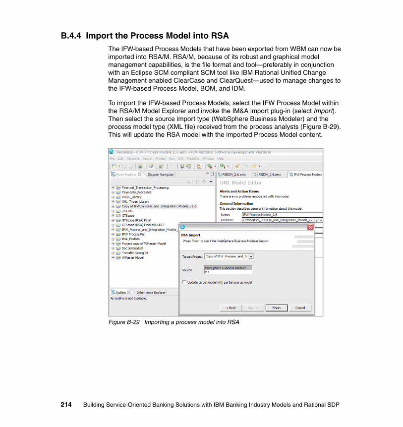
B.4.4 Import the Process Model into RSAThe IFW-based Process Models that have been exported from WBM can now be imported into RSA/M. RSA/M, because of its robust and graphical model management capabilities, is the file format and tool—preferably in conjunction with an Eclipse SCM compliant SCM tool like IBM Rational Unified Change Management enabled ClearCase and ClearQuest—used to manage changes to the IFW-based Process Model, BOM, and IDM.
To import the IFW-based Process Models, select the IFW Process Model within the RSA/M Model Explorer and invoke the IM&A import plug-in (select Import). Then select the source import type (WebSphere Business Modeler) and the process model type (XML file) received from the process analysts (Figure B-29). This will update the RSA model with the imported Process Model content.
Figure B-29 Importing a process model into RSA
214 Building Service-Oriented Banking Solutions with IBM Banking Industry Models and Rational SDP
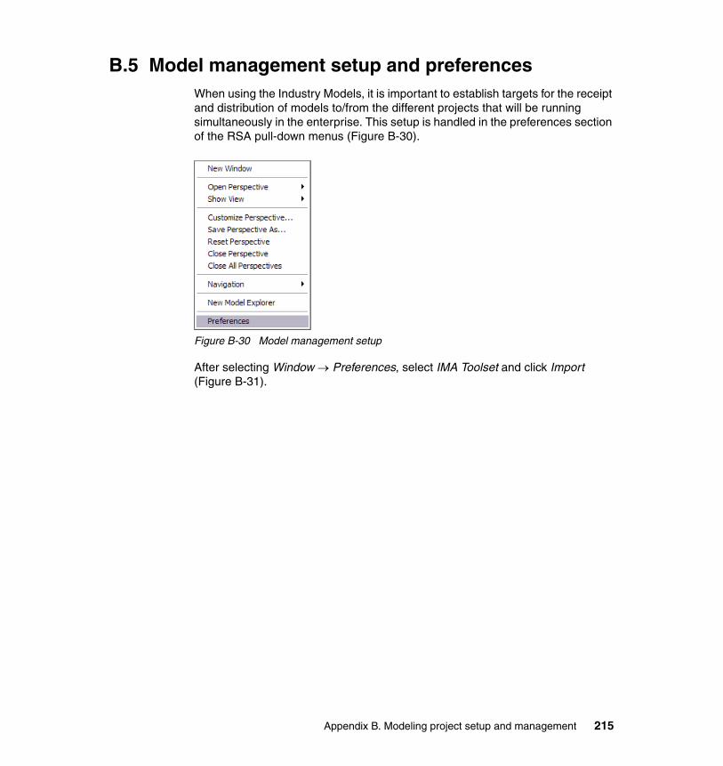
B.5 Model management setup and preferencesWhen using the Industry Models, it is important to establish targets for the receipt and distribution of models to/from the different projects that will be running simultaneously in the enterprise. This setup is handled in the preferences section of the RSA pull-down menus (Figure B-30).
Figure B-30 Model management setup
After selecting Window → Preferences, select IMA Toolset and click Import (Figure B-31).
Appendix B. Modeling project setup and management 215
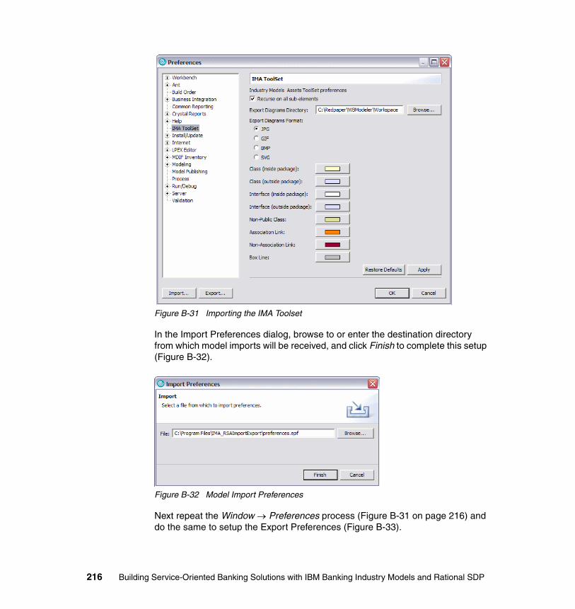
Figure B-31 Importing the IMA Toolset
In the Import Preferences dialog, browse to or enter the destination directory from which model imports will be received, and click Finish to complete this setup (Figure B-32).
Figure B-32 Model Import Preferences
Next repeat the Window → Preferences process (Figure B-31 on page 216) and do the same to setup the Export Preferences (Figure B-33).
216 Building Service-Oriented Banking Solutions with IBM Banking Industry Models and Rational SDP
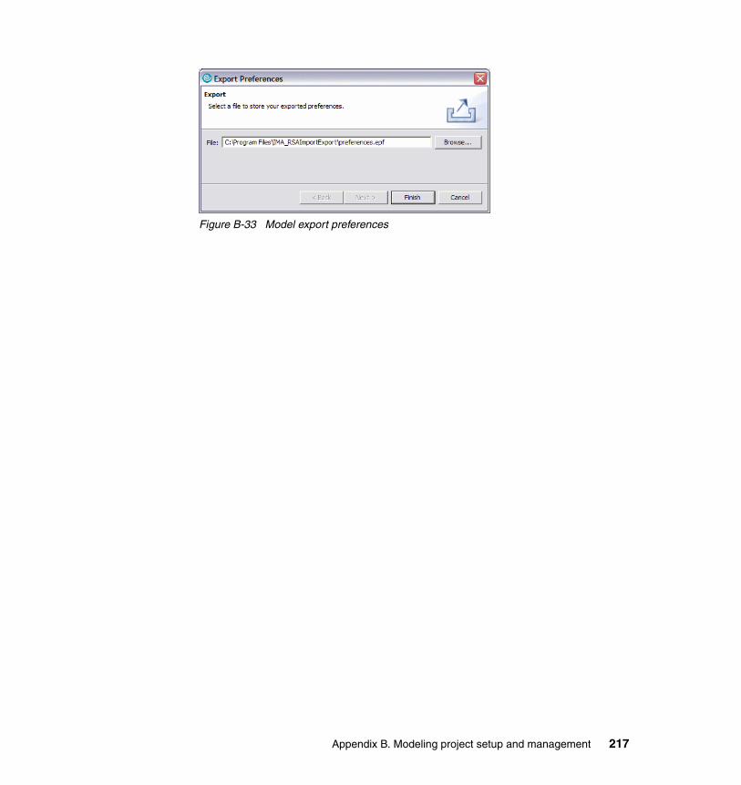
Figure B-33 Model export preferences
Appendix B. Modeling project setup and management 217

218 Building Service-Oriented Banking Solutions with IBM Banking Industry Models and Rational SDP

Appendix C. IMA generator options
In this appendix we describe the IMA generator options.
C
© Copyright IBM Corp. 2007. All rights reserved. 219
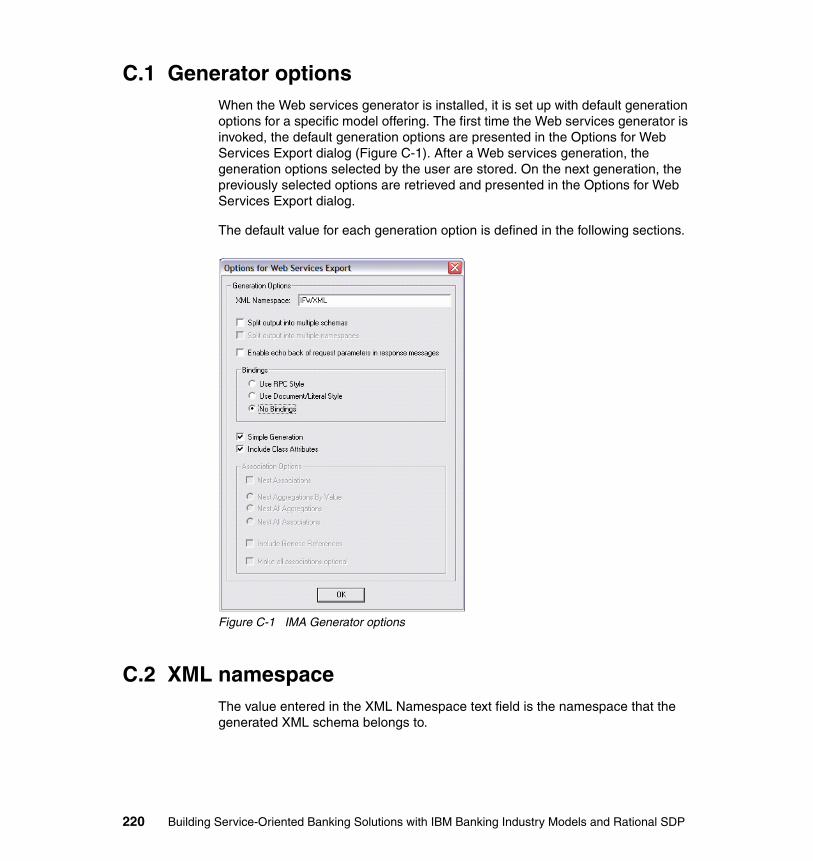
C.1 Generator optionsWhen the Web services generator is installed, it is set up with default generation options for a specific model offering. The first time the Web services generator is invoked, the default generation options are presented in the Options for Web Services Export dialog (Figure C-1). After a Web services generation, the generation options selected by the user are stored. On the next generation, the previously selected options are retrieved and presented in the Options for Web Services Export dialog.
The default value for each generation option is defined in the following sections.
Figure C-1 IMA Generator options
C.2 XML namespaceThe value entered in the XML Namespace text field is the namespace that the generated XML schema belongs to.
220 Building Service-Oriented Banking Solutions with IBM Banking Industry Models and Rational SDP
If Split output into multiple namespaces is selected, then the value in the XML Namespace field is used as the prefix for the namespace in each component schema.
The default values are IFWXML for IFW and IAAXML for IAA.
C.3 Enable echo back of request parameters in response messages
When Enable echo back of request parameters in response messages is selected, all the command parameters (in, out, and inout parameters) are returned in the command’s response message.
The default value for all model offerings is cleared.
C.4 Splitting optionsThe splitting options control whether:
� A single schema is generated � A schema is generated for each scoped component
The splitting options control whether split schemas:
� Belong to a single namespace� Have unique namespaces
When generating a single schema, one WSDL file is generated, containing:
� The standard XML definitions that are used across the entire scope of the generation (that is, the contents of the staticWS.txt file)
� The generated schema
� The types required for Web service parameters
� WSDL services
� WSDL messages
� WSDL port types
� WSDL bindings (optional)
Appendix C. IMA generator options 221
C.4.1 Split output into multiple schemasWhen Split output into multiple schemas is selected, an XML schema is generated for each scoped component. Each generated schema belongs to the namespace specified in the XML Namespace field.
A base XML schema with the name specified in the XML Namespace field is generated. This schema contains the standard XML definitions that are used across the entire scope of the generation (that is, the contents of the baseWS.txt file).
A WSDL file is generated containing:
� The types required for Web service parameters� WSDL services� WSDL messages� WSDL port types� WSDL bindings (optional)
When Split output into multiple schemas is selected:
� Required schemas are included into each generated schema.� Required schemas are included into the WSDL file.� The Base schema is included into all other generated schemas.
The default value for all model offerings is cleared.
C.4.2 Split output into multiple namespacesThe Split output into multiple namespaces option is only enabled when Split output into multiple schemas is selected.
When Split output into multiple namespaces is selected, each generated schema has its own namespace. The format for the namespace for each schema is:
<XML Namespace>_<Component Name>
Note: The exception to this is the Base schema, which belongs to the namespace specified in the XML Namespace field.
When Split output into multiple namespaces is selected:
� Required schemas are imported into each generated schema.� Required schemas are imported into the WSDL file.� The Base schema is imported into all other generated schemas.
The default value for all model offerings is cleared.
222 Building Service-Oriented Banking Solutions with IBM Banking Industry Models and Rational SDP
C.5 Binding optionsThe binding options control whether WSDL bindings are generated and the style of generated bindings.
A WSDL binding describes how a Web service is bound to the SOAP messaging protocol. The Web services generator can create two styles of WSDL SOAP binding:
� RPC/Literal style� Document/Literal Wrapped style
Note: The Document/Literal style has one main advantage over RPC/Literal style: everything that appears in the soap:body of the message is defined by the schema, so the message can be validated easily.
C.5.1 Use RPC styleWhen Use RPC Style is selected, RPC/Literal WSDL bindings are generated.
The default value for all model offerings is cleared.
C.5.2 Use Document/Literal styleWhen Use Document/Literal Style is selected, Document/Literal WSDL bindings are generated.
The default value for all model offerings is cleared.
C.5.3 No BindingsWhen No Bindings is selected, no WSDL bindings are generated.
The default value for all model offerings is selected.
C.6 Association optionsNavigable associations of a class can be created as attributes in the generated XML type for that class. The associations options control which navigable associations are created.
Appendix C. IMA generator options 223
C.6.1 Nest associationsWhen Nest Associations is cleared, navigable associations are not created in generated XML types. The other Association options are disabled when Nest Associations is cleared.
When Nest Associations is selected, the other Association options are enabled. Select one of the nest options to control which navigable associations are created in generated XML types.
Note: Navigable associations of a class with the <<overloaded>> stereotype are not created in the generated XML type for that class.
The default value for all model offerings is cleared.
C.6.2 Nest aggregations by value When Nest Aggregations By Value is selected, navigable associations of a class that are aggregated by value (Composition) are created in the generated XML type for that class.
The default value for all model offerings is selected.
C.6.3 Nest all aggregationsWhen Nest All Aggregations is selected, navigable associations of a class that are aggregated by value (Composition) or aggregated by reference (Aggregation) are created in the generated XML type for that class.
The default value for all model offerings is cleared.
C.6.4 Nest all associationsWhen Nest All Associations is selected, all navigable associations of a class are created in the generated XML type for that class.
The default value for all model offerings is cleared.
C.6.5 Include generic referencesWhen Include Generic References is selected, a GenericReference is generated for the following:
� Operations with the <<typenav>> stereotype� Out parameters for <<typenav>> operations� Navigable associations not created based on Association Options selections
224 Building Service-Oriented Banking Solutions with IBM Banking Industry Models and Rational SDP

The default values are cleared for IFW and selected for IAA.
C.6.6 Make all associations optionalWhen Make all associations optional is selected, all navigable associations are created in generated XML types with a minOccurs of 0.
The default value for all model offerings is cleared.
Appendix C. IMA generator options 225

226 Building Service-Oriented Banking Solutions with IBM Banking Industry Models and Rational SDP
acronyms
BOM Business object model
BOT Boundary of type
BPEL Business Process Execution Language
BUC Business use case
CBM Component Business Model
CICS Customer Information Control System
EJB Enterprise JavaBean
FSFM Financial Services Function Model
FSS Financial services sector
IAA Insurance Application Architecture
IDM Interface design model
IFW Banking Industry Enterprise Models
IM&A Industry models and assets organization
IMA Industry modelsand assets organization
IPS Industry Platform and Solutions
ITSO International Technical Support organization
JDM Java Design Model
JSP JavaServer pages
OMG Object Management Group
RAD Rational Application Developer
RAS Reusable Asset Specification
ReqPro Rational RequisitePro
RPC Remote procedure call
RSA Rational Software Architect
Abbreviations and
© Copyright IBM Corp. 2007. All rights reserved.
RSA/M Rational Software Architect/ Rational Software Modeler
RSA/RSM Rational Software Architect/ Rational Software Modeler
RSM Rational Software Modeler
RUP Rational Unified Process
SDP Software Delivery Platform
SOA Service-oriented architecture
SOMA Service-Oriented Methodology and Architecture
SSN Social security number
UC Use case
UML Unified Modeling Language
URL Unified Resource Locator
WBM WebSphere Business Modeler
WID WebSphere Integration Developer
WPS WebSphere Process Server
WSDL Web Services Description Language
XML EXtensible Markup Language
XSD XML Schema Definition
227

228 Building Service-Oriented Banking Solutions with IBM Banking Industry Models and Rational SDP

Related publications
The publications listed in this section are considered particularly suitable for a more detailed discussion of the topics covered in this Redpaper.
IBM RedbooksFor information about ordering these publications, see “How to get IBM Redbooks” on page 232. Note that some of the documents referenced here may be available in softcopy only.
� Building SOA Solutions Using the Rational SDP, SG24-7356
� Understanding SOA Security Design and Implementation, SG24-7310
� Best Practices for SOA Management, REDP-4233
� Patterns: SOA Foundation Service Creation Scenario, SG24-7240
� Patterns: SOA Foundation Service Connectivity Scenario, SG24-7228
� Patterns: Extended Enterprise SOA and Web Services, SG24-7135
� Patterns: SOA Foundation - Business Process Management Scenario, SG24-7234
� Patterns: Integrating Enterprise Service Buses in a Service-Oriented Architecture, SG24-6773
� Patterns: SOA with an Enterprise Service Bus in WebSphere Application Server V6, SG24-6494
� Patterns: Implementing Self-Service in an SOA Environment, SG24-6680
� Powering SOA with IBM Data Servers, SG24-7259
© Copyright IBM Corp. 2007. All rights reserved. 229
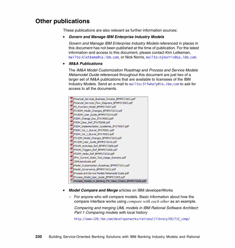
Other publicationsThese publications are also relevant as further information sources:
� Govern and Manage IBM Enterprise Industry Models
Govern and Manage IBM Enterprise Industry Models referenced in places in this document has not been published at the time of publication. For the latest information and access to this document, please contact Kim Letkeman, mailto:[email protected], or Nick Norris, mailto:[email protected].
� IM&A Publications
The IM&A Model Customization Roadmap and Process and Service Models Metamodel Guide referenced throughout this document are just two of a larger set of IM&A publications that are available to licensees of the IBM Industry Models. Send an e-mail to mailto:[email protected] to ask for access to all the documents.
� Model Compare and Merge articles on IBM developerWorks
– For anyone who will compare models. Basic information about how the compare interface works using compare with each other as an example.
Comparing and merging UML models in IBM Rational Software Architect: Part 1 Comparing models with local history
http://www-128.ibm.com/developerworks/rational/library/05/712_comp/
230 Building Service-Oriented Banking Solutions with IBM Banking Industry Models and Rational
– For anyone who will merge models. Basic information about how merging works using compare with each other as an example. Contrasts two-way and three-way merging.
Comparing and merging UML models in IBM Rational Software Architect: Part 2 Merging models using compare with each other
http://www-128.ibm.com/developerworks/rational/library/05/712_comp2/
– For anyone who wants to understand why RSA's merge support works in certain ways. Also for a deeper understanding of the deltas themselves, for example, how EMF deltas map onto UML gestures. Also discusses model partitioning.
Comparing and merging UML models in IBM Rational Software Architect: Part 3 A deeper understanding of model merging
http://www-128.ibm.com/developerworks/rational/library/05/802_comp3/
– For anyone who is responsible for setting up the team repositories and who may be involved in resolving parallel development issues. Although written around CVS, most of the information is applicable to ClearCase as well.
Comparing and merging UML models in IBM Rational Software Architect: Part 4 Parallel model development with CVS
http://www-128.ibm.com/developerworks/rational/library/05/0809_CVS4/
– For anyone who is responsible for the partitioning or management of models at the enterprise or team level.
Comparing and merging UML models in IBM Rational Software Architect, Part 5: Model management with IBM Rational ClearCase and IBM Rational Software Architect Version 7 and later
http://www-128.ibm.com/developerworks/rational/library/07/0703_letkeman/
– For anyone who is responsible for custom profiles that provide domain-specific icons, attributes, and shapes. Discusses extremely important issues surrounding parallel development with these profiles. Also provides a basic tutorial on how to create one.
Comparing and merging UML models in IBM Rational Software Architect, Part 6: Parallel model development with custom profiles
http://www-128.ibm.com/developerworks//rational/library/05/0823_Letkeman/
– For anyone who practices ad hoc modeling or who will run any of the Java, C++, or C# to UML transforms and has to understand the combine model’s user interface and features.
Related publications 231
Comparing and merging UML models in IBM Rational Software Architect V7.0, Part 7: Ad-hoc modeling – Fusing two models with diagrams
http://www-128.ibm.com/developerworks/rational/library/07/0410_letkeman/
Related Articles
– For anyone who desires an introduction to model structure best practices for the RSx family of products in Version 6.
Model Structure Guidelines for Rational Software Modeler and Rational Software Architect
http://www-128.ibm.com/developerworks/rational/library/5816.html
Online resourcesThese Web sites are also relevant as further information sources:
� IBM Software
http://www.ibm.com/softwarehttp://www.ibm.com/software/rational
� IBM Software Support
http://www.ibm.com/support
� IBM developerWorks
http://www.ibm.com/developer
How to get IBM RedbooksYou can search for, view, or download Redbooks, Redpapers, Hints and Tips, draft publications and Additional materials, as well as order hardcopy Redbooks or CD-ROMs, at this Web site:
ibm.com/redbooks
Help from IBMIBM Support and downloads
ibm.com/support
IBM Global Services
ibm.com/services
232 Building Service-Oriented Banking Solutions with IBM Banking Industry Models and Rational
Index
Aabstraction 133analysis
elements 98model 19
analyzeprocesses 19services 19
Application Developer 20asset 12automation 40
BBanking Industry Enterprise Models
see IWFbanking solutions 3BOM xiii, 9
class 131IWF 40service candidates 64
BOT 85, 93diagram 93, 133
bottom-upapproach 9
boundary of type 85BPEL 7
generation 180BUC 32, 54business
activity 65analysis 19analyst xiiidrivers 18functional scope 22, 24functions 31goals 22–23information connectors 49integration specialist 12items 38, 161model 12motivation 77opportunities 55opportunity 80
© Copyright IBM Corp. 2007. All rights reserved.
requirement 56optimization 2process 12, 31
elements 38graphical 41resources 38
requirements 9, 19roles 38rules 38scope 81task 8, 40use case 32view 12
Business Modeler 19, 38Business Object Model
see BOMBusiness Process Execution Language 7, 152business process execution language 7business-driven development 16
CCBM 25CICS 7ClearCase 23, 63ClearQuest 23, 63COBOL 7collaboration 118collaborative development environment 13communication diagram 119component 13, 112
dependencies 136Component Business Model 24configuration management 39control flow 168Customization xii
Roadmap xii
Ddecision
branches 168decompose 39dependency
relationship 101, 115
233
designpractices 12processes 20services 19
duration 44
EEJB 143enterprise models 2expression builder 171
FFinancial Services Function Model 22flow control 168FSFM 22, 24
Gglobal task 47, 160
editor 179Govern and Manage Enterprise Models 17governance 12, 63
Hhardware configuration 186
IIAA xi, 2, 6IDM xiii
class 132model 128
collaboration 117componen 132implemntation 20interface 110, 142IWF 40operation 106patterns 7realization 108, 114service design 97structural component 162
IFW 2–3, 6modeling conventions 47overview 16transactional components 163
IM&A xiigenerators 141Java Design Model 142
IMA xiigenerator
options 219implementation 183industry models xi, 6
installation 190industry models and assets organization xiiin-scope 32installation 186Insurance Application Architecture
see IAAinsurance models xiIntegration Developer 20Interface Design Model
see IDMIT
optimization 2scope 80
JJ2EE 62
architecture 7environment 7
Java Design Model 20JDM 20, 141
Llocal task 46, 160loopback 174
Mmessage pathways 123model
customization 7management 215validation 140
modeling project 195
OObject Management Group 62OMG 62opportunity 79optimization 2
Ppatterns 6portal applications 62
234 Building Service-Oriented Banking Solutions with IBM Banking Industry Models and Rational SDP

priorityattribute 34
processanalysis 19, 38, 64
model 154design 20, 151
project 154export 154implementation 20, 183service
boundary 158simulation 179
Process Design Model 20Process Server 152project
management 191scope 18, 22setup 191
RRational
Application Developer 20ClearCase 23ClearQuest 23Product Updater 187RequisitePro 18
installtion 190Rose 188Software Architect 19
installation 187Software Modeler 19Sofware Delivery Platform
see SDPUnified Process 16
Redbooks Web site 232Contact us xv
regulatory requirements 44, 78requirement
coverage 28record 73
RequisitePro 18, 22, 63project
setup 192template 54, 63
Requirement Explorer 68WBM link 54
resource assignments 176Reusable Asset Specification 195
roadmap 8role 177RSA 23RSA/M 19RSM 23RUP 16
Sscenario 16
roadmap 8, 17SCM 39scope 80SDP xi, 3
introduction 11service
analysis 61model 19
analyst xiiicandidate 64, 72
use case 85use cases 8
collaboration 120design 19, 97implementation 20, 183interface design 104level agreement 12
service-oriented architecturesee SOA
simulation 179SLA 12SOA 62
projects 6software
architect 12configuration 186development 13factory 12
Software Architect 19Software Delivery Platform
see SDPSoftware Modeler 19, 63solution
architect xiiiconstraints 9
SOMA 16
Ttooling infrastructure 13
Index 235
top-downapproach 9
traceability 13matrix 26, 76relationship 26tree 28
UUML 7, 62
Java transformation 149model 8modeling techniques 91use case element 70
Unified Modeling Languagesee UML
use case 8, 32diagram 91external view 90, 106
WWeb Services Description Language 8WebSphere
Business Modeler 19installation 189
Integration Developer 20, 174, 184installation 188
Process Server 152, 180workflow 152workstation configuration 185WSDL 8
XXML
message 7XSD
data definitions 162
236 Building Service-Oriented Banking Solutions with IBM Banking Industry Models and Rational SDP

Building Service-Oriented Banking Solutions with
IBM Banking Industry M
odels and Rational SDP


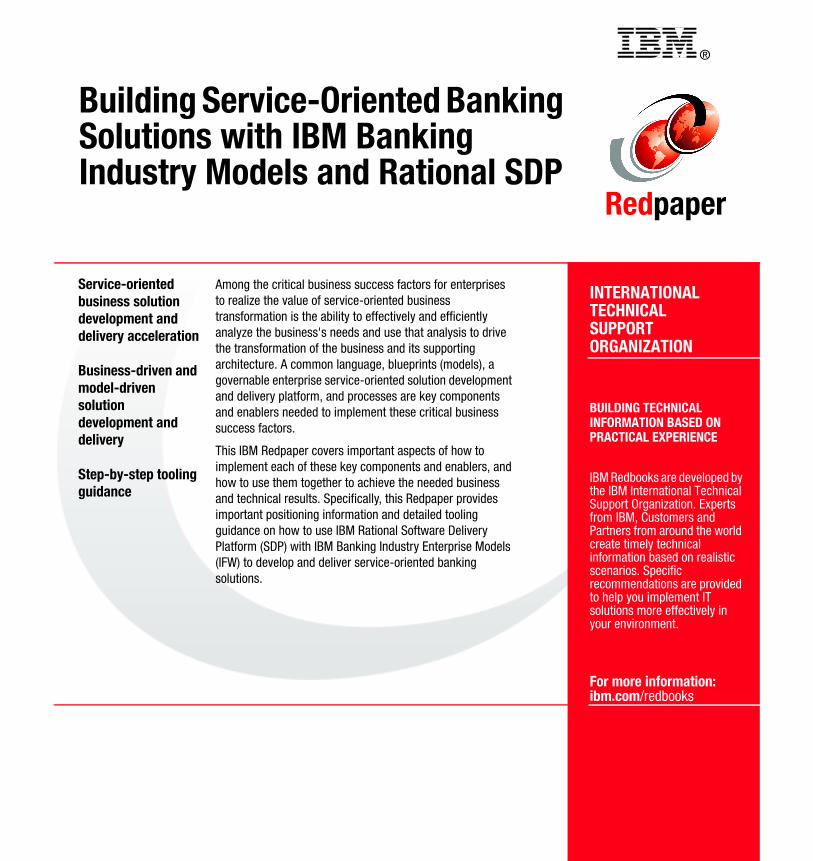
®
INTERNATIONAL TECHNICALSUPPORTORGANIZATION
BUILDING TECHNICALINFORMATION BASED ONPRACTICAL EXPERIENCE
IBM Redbooks are developed by the IBM International Technical Support Organization. Experts from IBM, Customers and Partners from around the world create timely technical information based on realistic scenarios. Specific recommendations are provided to help you implement IT solutions more effectively in your environment.
For more information:ibm.com/redbooks
Redpaper
Building Service-Oriented Banking Solutions with IBM Banking Industry Models and Rational SDP
Service-oriented business solution development and delivery acceleration
Business-driven and model-driven solution development and delivery
Step-by-step tooling guidance
Among the critical business success factors for enterprises to realize the value of service-oriented business transformation is the ability to effectively and efficiently analyze the business's needs and use that analysis to drive the transformation of the business and its supporting architecture. A common language, blueprints (models), a governable enterprise service-oriented solution development and delivery platform, and processes are key components and enablers needed to implement these critical business success factors.
This IBM Redpaper covers important aspects of how to implement each of these key components and enablers, and how to use them together to achieve the needed business and technical results. Specifically, this Redpaper provides important positioning information and detailed tooling guidance on how to use IBM Rational Software Delivery Platform (SDP) with IBM Banking Industry Enterprise Models (IFW) to develop and deliver service-oriented banking solutions.
Back cover