building envelope failure case studies in high-rise ... · building envelope failure case studies...
TRANSCRIPT
BEST2 – Design and Rehabilitation –Session EE4-2
BUILDING ENVELOPE FAILURE CASE STUDIES IN HIGH-RISE CONSTRUCTION
Pierre-Michel Busque, P.Eng.1
1 Pierre-Michel Busque, P.Eng., Busque Engineering Limited, Richmond, British Columbia, Canada.
ABSTRACT
Many argue that through improved education, developers will increase their desire to make available the
necessary budgets to construct more durable and better performing buildings; so therefore, more
elaborate building codes may not be necessary. Unfortunately, in order to produce competitively priced
buildings, developers are under pressure to build to the Standard prescribed by the Building Code (herein
referred to as the “Minimum Standard”). However, the Standard of Care required of reasonable and
prudent engineers and architects is sometimes above this Minimum Standard. In the zone between the
Minimum Standard and the Standard of Care of a reasonable and prudent practitioner, lies an area where
ignorance can be a marketable commodity. Through ignorance, willingness to design and implement
inferior designs can improve business opportunities while increasing the risk of localized or systemic
building envelope failures.
Vancouver’s building envelope failures, over 20 years, have provided a wealth of knowledge about what
can go wrong with building envelopes. Unfortunately, the knowledge gained is not efficiently
incorporated into the design industries’ knowledge base because the mechanisms to do so are lacking.
To compound the problem, settlements of claims between building owners and the design and
construction teams are usually confidential, reducing the likelihood that the lessons of building failures
are absorbed into the design industries’ knowledge base.
This paper will review, with the author’s opinion on the expected Standard of Care, case studies of
waterproofing, cladding, glazing and roofing failures and possible construction improvements.
INTRODUCTION
Vancouver has experienced a large number of building envelope failures in the last two decades. Through
repairing these failures, professionals have accumulated a wealth of information on the types of
construction materials and building assemblies that are likely to be durable and on those that are not
likely to be. What to do with this precious body of knowledge has been the subject of many
disagreements. Should building code be made more rigorous, enshrining in law the lessons learnt from
building failures in hopes of achieving a minimum level of performance? Should we educate our clients
in hopes that the knowledge we communicate will allow them to dismiss traditional views and enable
them to free up additional capital to improve the building’s design?
Often, when a building developer is confronted by an objection from the building envelope consultant
regarding the use of a material or of a building assembly, the developer is forced to look at his past
experience and consider the following questions:
• What is the cost of the design change requested by the building envelope engineer?
• Has the objectionable detail been used on other projects and has it performed?
• Is the objectionable detail allowable by Code?
If the costs of the desired change are important, and the objectionable detail is allowable by Code, the
course of action frequently adopted by the developer is to terminate the service of the building envelope
engineer and to retain another that does not find the objectionable detail so objectionable. Ignorance on
the part of the building envelope consultant thus becomes a marketable commodity.
The following case studies show where the building envelope assemblies have fallen below the level of
performance expected by the building occupants. The reader can decide for himself if the Standard of
Care expected of reasonable and prudent building designers and developers has been breached.
CASE STUDIES
Cast-In-Place Concrete Walls
The following example deals with above-grade concrete exposed to elements such as rain and solar
radiation. Cast-in place concrete walls have gained in popularity in the last decade. This is partly due
to the cost savings that can be realized by the concrete’s ability to satisfy the wall’s structural
requirements while serving as its exterior façade. Due to concrete’s ability to resist deterioration in wet
conditions, the public has inferred that building envelope failures are unlikely to be as severe in concrete
buildings. This is not always true. The following concerns are associated with cast-in-place concrete
buildings:
Water Vapor Entrapment. “In a general mix of concrete, one cubic metre requires 210 litres of
water or more during the mix, but with hydration, eventually retains slightly less than 120 litres of
water. ...This water would be released within the first two years and probably most of it within the
first year...” (Quirouiette, R.L. 1983)
This signifies that an 8 inch thick concrete wall will release 18 L/m2 during the first few years. Assuming
that half of this moisture (or 9 L) will be released to the exterior, the other half will be released to the
interior of the wall assembly.
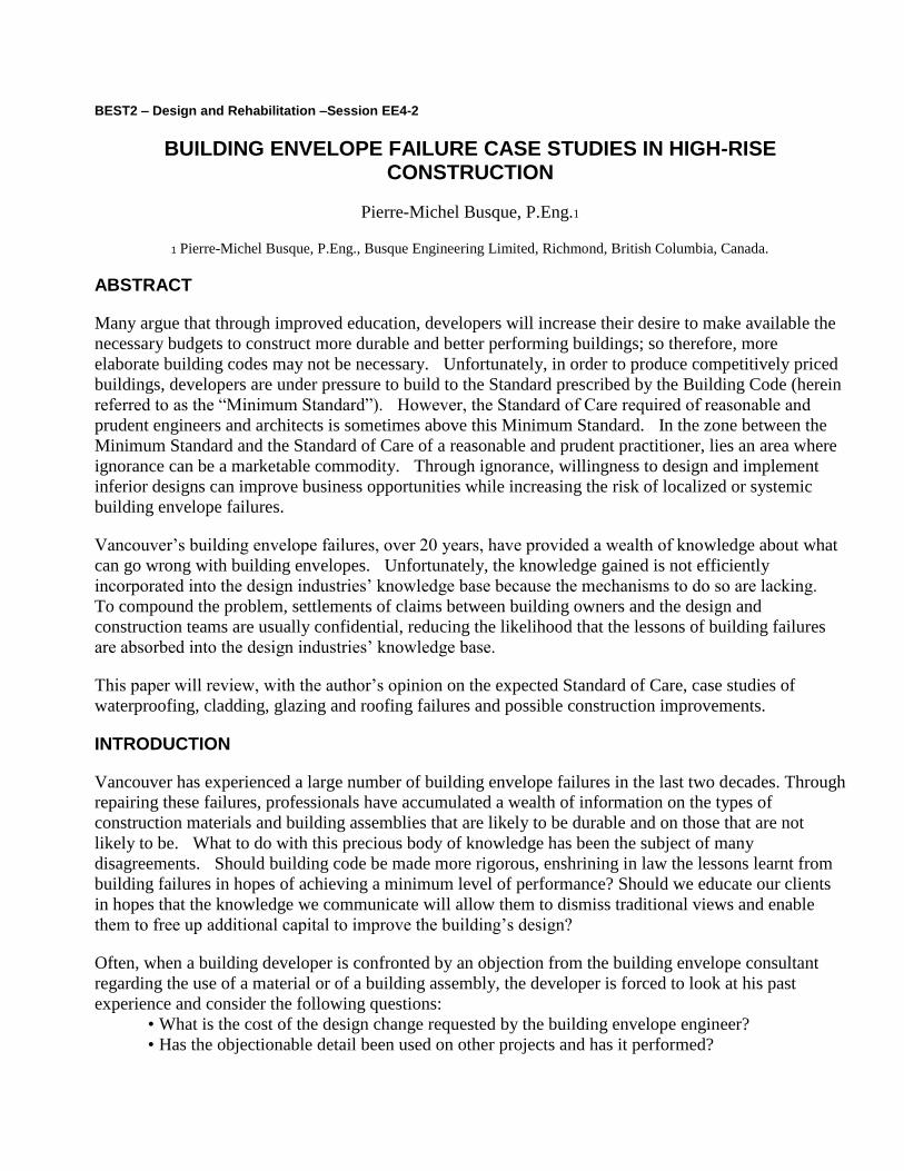
The traditional cast in place concrete wall assembly is shown below.
FIGURE 1: Components-listed from the exterior to the interior:
• Concrete
• Air space
• Glass fibre insulation (between steel studs)
• Polyethylene vapour barrier Gypsum board
This building assembly contains planes of low vapour permeance on the interior side and on the exterior faces of the wall. As moisture is released from the concrete on the interior side of the wall, the polyethylene will impede the drying process of the wall due to its low vapour permeance and the steel studs and fibreglass insulation will be subjected to a humid environment for a substantial period of time. If the air temperature inside of the dwelling is below the dew point temperature of the air within the stud cavity, condensation will form on the polyethylene vapour barrier. When the concrete cools below the dew point of the air of the stud cavity, condensation will form on the concrete and on the steel studs.
The presence of two planes of low vapour permeances either side of a thermal resistance with a high vapour permeance and capacity to absorb moisture transform this assembly into an assembly that will accumulate moisture more readily than it will release it. For the purpose of this paper, this type of assembly will be referred to as moisture “Accumulator”. Building envelope assemblies that are conceived to easily dissipate moisture through the process of drainage, ventilation or diffusion will be referred to as “Dissipaters”.
The Standard of Care required of a prudent and reasonable design professional is to design a building assembly that is tolerant of incidental moisture. Incidental moisture can be released by wet materials after construction. Moisture can also be caused by diffusive vapour transport or condensation due to air leakage. Ideally, a properly conceived building envelope assembly should only suffer localized damage if a leak develops due to an error in construction or due to damage from an outside force. Some wall assemblies readily store moisture without providing indications to the occupants that the building envelope is deteriorating. In the author’s opinion, a building envelope assembly that accumulates moisture more readily than it dissipates it is more likely to suffer systemic (large scale) failure. Hence, although a conventional wall assembly may meet the standard of care of a reasonable and prudent design professional, in circumstances where a wall’s exposure to wind driven rain is high, it is good practice to design a wall that will readily show damage moisture accumulates within the assembly.
Most of the buildings with cast-in-place concrete walls will not report performance problems. This said, problems are frequently reported with this building envelope assembly. Typical problems include leakage of cracks or joints in the concrete and drying of moisture from the concrete into the interior stud cavity of the wall.
In the opinion of the author, the traditional cast-in-place wall assembly can be improved by means such as installing Exterior Insulated Finish System (EIFS) on the exterior face of the concrete and leaving the wall cavity empty and not installing a polyethylene vapour barrier on the interior face of the steel studs. EIFS, properly detailed, would provide the following benefits:
• Cover the exterior joints of the concrete that can leak to the interior;
• Force the temperature gradient to the exterior side of the concrete, reducing the risk of
condensation on the interior side of the concrete; and
• Allow diffusion drying the concrete to the interior of the building.
Unfortunately, by the time a building envelope consultant is retained by the developer, development
permits are frequently in place and the choice of exterior finishes for the building cannot be modified. In
lieu of installing EIFS to the exterior wall, the author has experience good success for the last decade by
utilizing closed cell polyurethane insulation on the interior side of the concrete walls between the studs.
A polyethylene vapour retarder is not utilized in such cases.
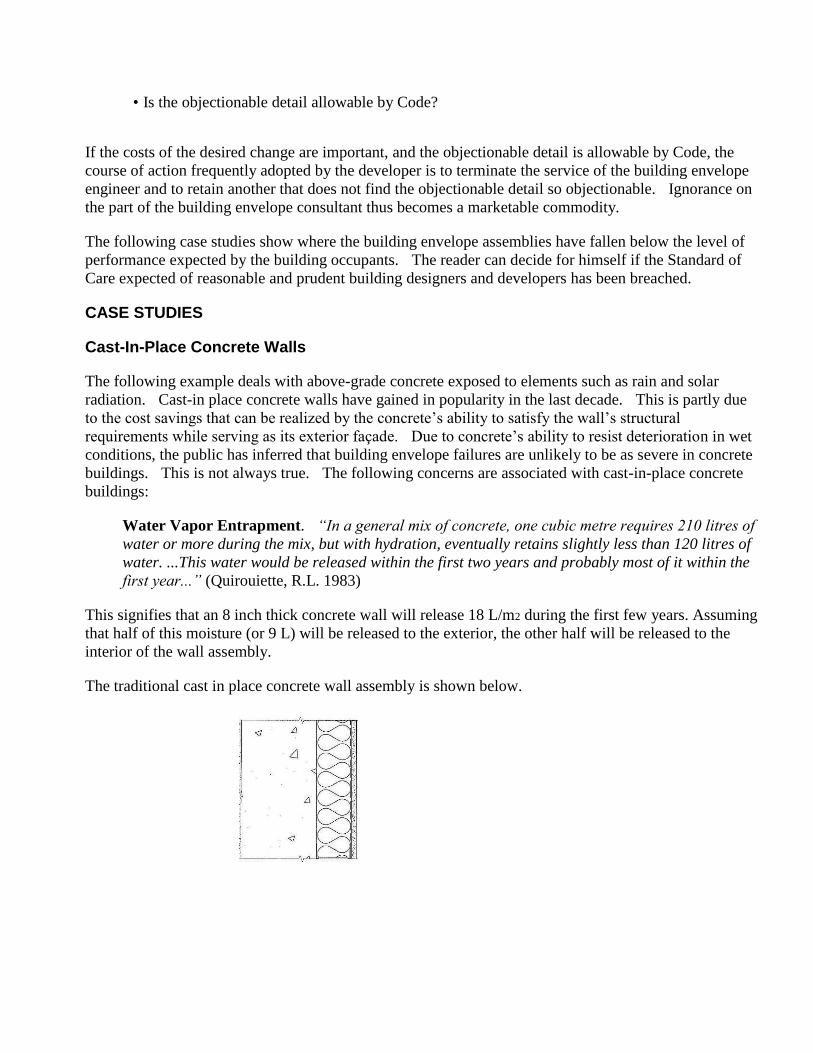
On one project that the author worked on, the cost of implementing the options mentioned above to
improve the traditional cast-in-place concrete wall was approximately $100,000. The developers opted
to replace the building envelope engineer rather than spend the funds necessary to improve the design of
the wall assembly.
Photograph 1: Closed-cell spray applied polyurethane foam was utilized on the interior side of the
cast-in place concrete wall as insulation during the retrofit of this building in 2005.
Elastomeric Paint on Eyebrows
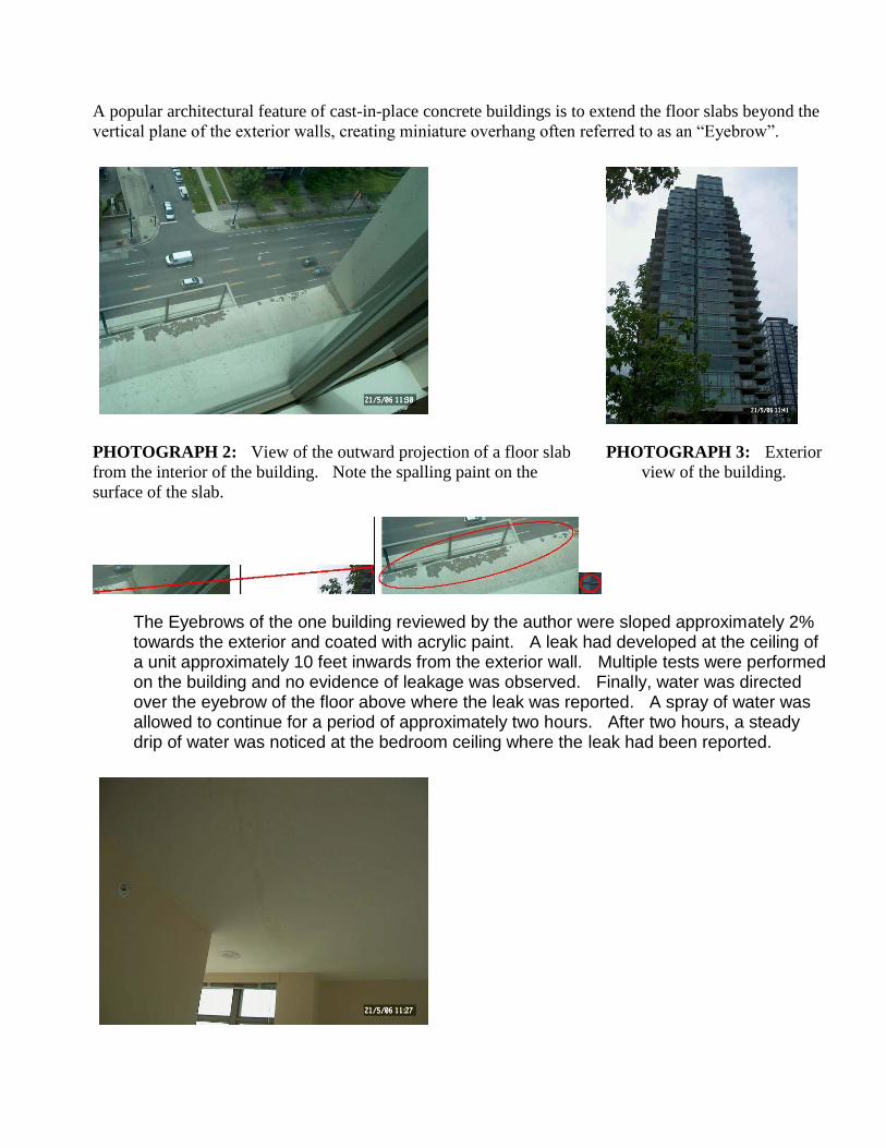
A popular architectural feature of cast-in-place concrete buildings is to extend the floor slabs beyond the
vertical plane of the exterior walls, creating miniature overhang often referred to as an “Eyebrow”.
PHOTOGRAPH 2: View of the outward projection of a floor slab
from the interior of the building. Note the spalling paint on the
surface of the slab.
PHOTOGRAPH 3: Exterior
view of the building.
The Eyebrows of the one building reviewed by the author were sloped approximately 2% towards the exterior and coated with acrylic paint. A leak had developed at the ceiling of a unit approximately 10 feet inwards from the exterior wall. Multiple tests were performed on the building and no evidence of leakage was observed. Finally, water was directed over the eyebrow of the floor above where the leak was reported. A spray of water was allowed to continue for a period of approximately two hours. After two hours, a steady drip of water was noticed at the bedroom ceiling where the leak had been reported.
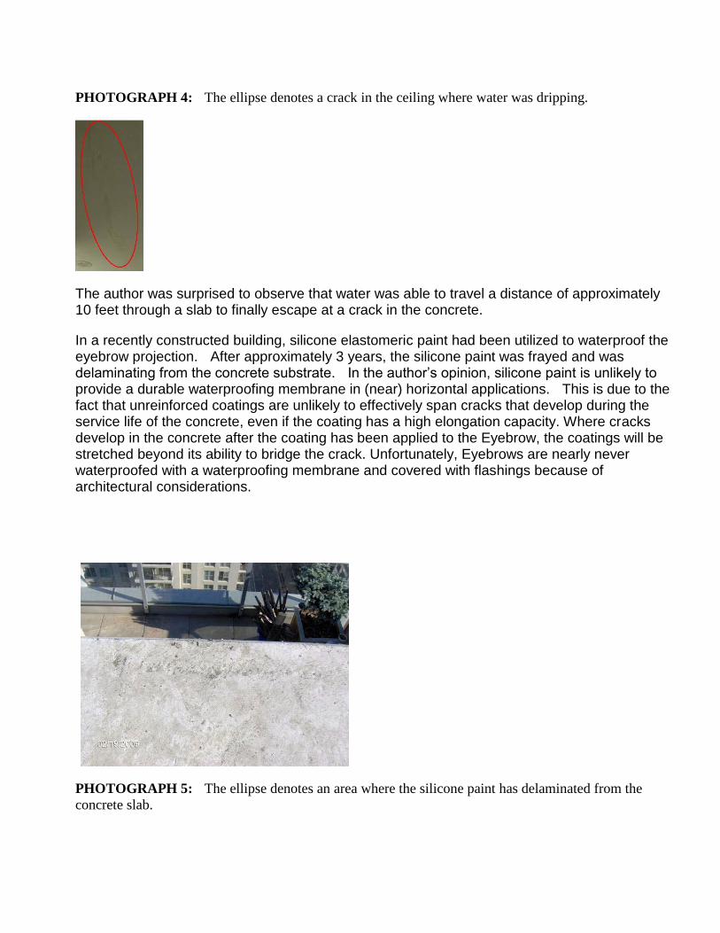
PHOTOGRAPH 4: The ellipse denotes a crack in the ceiling where water was dripping.
The author was surprised to observe that water was able to travel a distance of approximately 10 feet through a slab to finally escape at a crack in the concrete.
In a recently constructed building, silicone elastomeric paint had been utilized to waterproof the eyebrow projection. After approximately 3 years, the silicone paint was frayed and was delaminating from the concrete substrate. In the author’s opinion, silicone paint is unlikely to provide a durable waterproofing membrane in (near) horizontal applications. This is due to the fact that unreinforced coatings are unlikely to effectively span cracks that develop during the service life of the concrete, even if the coating has a high elongation capacity. Where cracks develop in the concrete after the coating has been applied to the Eyebrow, the coatings will be stretched beyond its ability to bridge the crack. Unfortunately, Eyebrows are nearly never waterproofed with a waterproofing membrane and covered with flashings because of architectural considerations.
PHOTOGRAPH 5: The ellipse denotes an area where the silicone paint has delaminated from the
concrete slab.
The Standard of Care required of a reasonable and prudent building envelope designer is to design a building envelope assembly that is tolerant to incidental moisture (and not leak). Based on several buildings, it is the opinion of the author, that a waterproofing membrane should be utilized on horizontal and near horizontal building surfaces. This said, it is also the experience of the Author that it is not always possible to convince a Developer that the extra cost involved in providing a waterproofing membrane in this location is worthwhile.
Membrane on Concrete Parapet Walls
It is a preferred detail of the architectural community to design concrete walls that extend above the
surface of the roof. These walls are referred to as parapet walls. Frequently, architects will require that
the top of the concrete walls remain unprotected from the elements in order to create the aesthetic effect
that they desire. This was an architectural feature favored by the late architect Arthur Erikson. At
times, the resistance to installing a waterproofing membrane on top of a parapet wall can be obstinate.
Convincing the architect that concrete cracks and that water can travel into the cracks down the parapet
wall height to accumulate beneath the roofing and into the occupied space below is usually not difficult.
Convincing the architect that he has to modify the appearance of the building usually is.
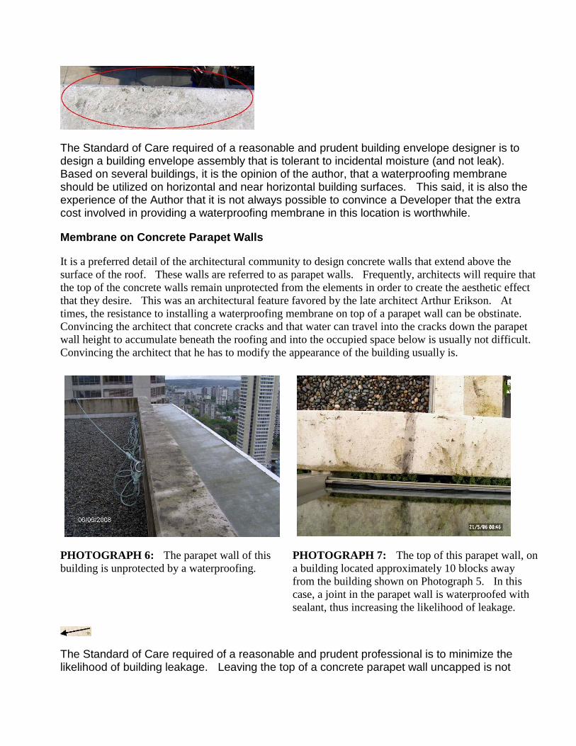
PHOTOGRAPH 6: The parapet wall of this
building is unprotected by a waterproofing.
PHOTOGRAPH 7: The top of this parapet wall, on
a building located approximately 10 blocks away
from the building shown on Photograph 5. In this
case, a joint in the parapet wall is waterproofed with
sealant, thus increasing the likelihood of leakage.
The Standard of Care required of a reasonable and prudent professional is to minimize the likelihood of building leakage. Leaving the top of a concrete parapet wall uncapped is not
minimizing the likelihood of building leakage. Although regulations existed 20 years ago that required the top of parapet walls to be capped, the present building code are more performance-based. Thus the choice of whether or not to install capping on a parapet wall or not to is left to the designers. Where the designer is ignorant of the risks of leakage, the parapet walls sometimes go uncovered.
Performance-based code may not always be effective when there is a lack of consensus on the level of performance of construction details. Performance-based codes are useful to define the performance that building designers are required to attain. In Canada, Canada Mortgage and Housing Corporation (CMHC) has published a number of “Best Practice Guides” that can provide designers with prescriptive methods of obtaining the desired performance.
Where insurance companies are required to provide third party warranties on building performance, prescriptive standards, based upon case histories of building envelope problems, can be developed by these companies to help address regional design requirements. Performance-based codes used by designers that do not have adequate knowledge or experience, will not yield buildings that perform well in all cases.
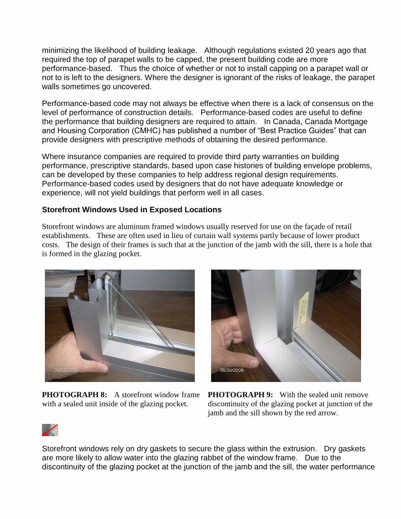
Storefront Windows Used in Exposed Locations
Storefront windows are aluminum framed windows usually reserved for use on the façade of retail
establishments. These are often used in lieu of curtain wall systems partly because of lower product costs. The design of their frames is such that at the junction of the jamb with the sill, there is a hole that
is formed in the glazing pocket.
PHOTOGRAPH 8: A storefront window frame
with a sealed unit inside of the glazing pocket.
PHOTOGRAPH 9: With the sealed unit remove
discontinuity of the glazing pocket at junction of the
jamb and the sill shown by the red arrow.
Storefront windows rely on dry gaskets to secure the glass within the extrusion. Dry gaskets are more likely to allow water into the glazing rabbet of the window frame. Due to the discontinuity of the glazing pocket at the junction of the jamb and the sill, the water performance
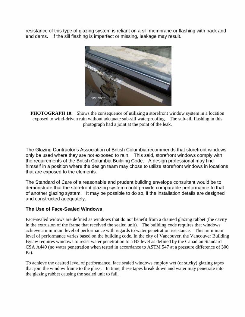
resistance of this type of glazing system is reliant on a sill membrane or flashing with back and end dams. If the sill flashing is imperfect or missing, leakage may result.
PHOTOGRAPH 10: Shows the consequence of utilizing a storefront window system in a location
exposed to wind-driven rain without adequate sub-sill waterproofing. The sub-sill flashing in this
photograph had a joint at the point of the leak.
The Glazing Contractor’s Association of British Columbia recommends that storefront windows only be used where they are not exposed to rain. This said, storefront windows comply with the requirements of the British Columbia Building Code. A design professional may find himself in a position where the design team may chose to utilize storefront windows in locations that are exposed to the elements.
The Standard of Care of a reasonable and prudent building envelope consultant would be to demonstrate that the storefront glazing system could provide comparable performance to that of another glazing system. It may be possible to do so, if the installation details are designed and constructed adequately.
The Use of Face-Sealed Windows
Face-sealed widows are defined as windows that do not benefit from a drained glazing rabbet (the cavity
in the extrusion of the frame that received the sealed unit). The building code requires that windows
achieve a minimum level of performance with regards to water penetration resistance. This minimum
level of performance varies based on the building code. In the city of Vancouver, the Vancouver Building
Bylaw requires windows to resist water penetration to a B3 level as defined by the Canadian Standard
CSA A440 (no water penetration when tested in accordance to ASTM 547 at a pressure difference of 300
Pa).
To achieve the desired level of performance, face sealed windows employ wet (or sticky) glazing tapes
that join the window frame to the glass. In time, these tapes break down and water may penetrate into
the glazing rabbet causing the sealed unit to fail.
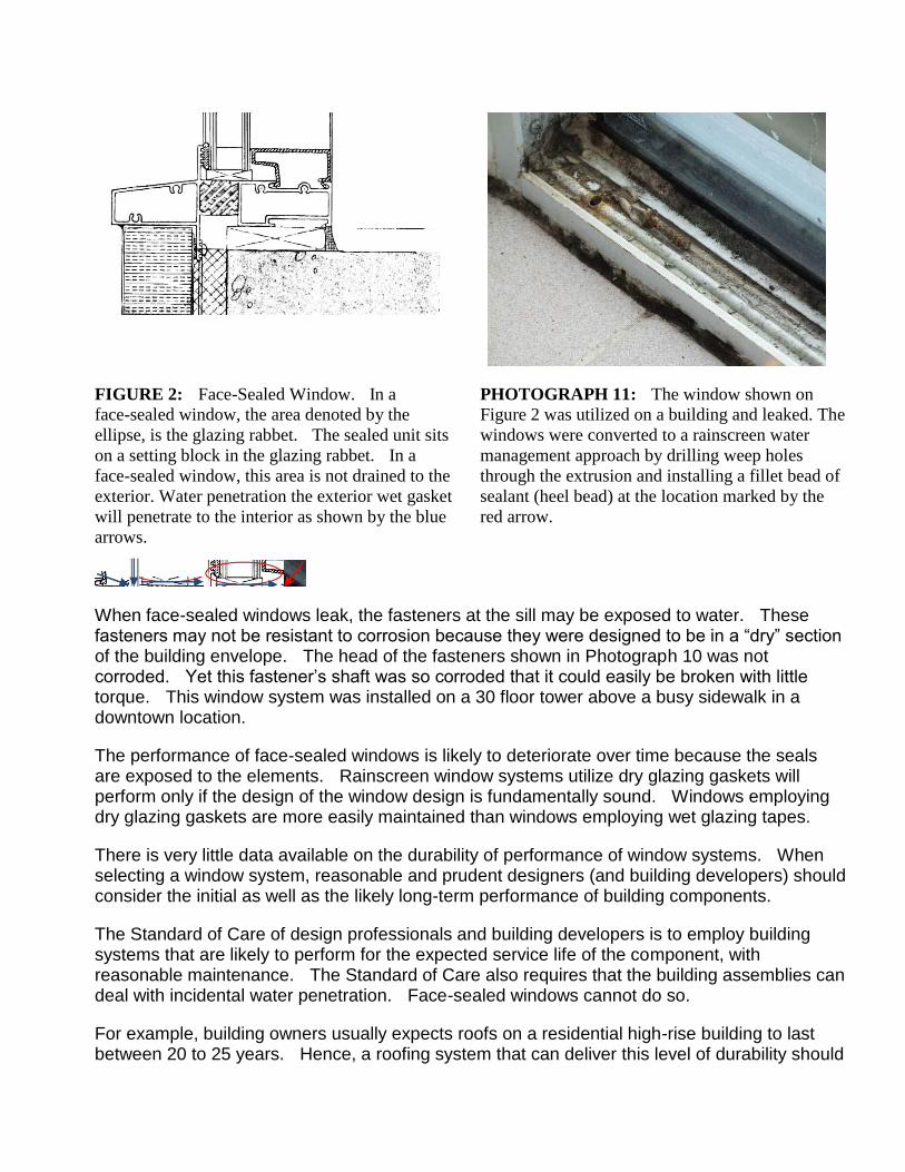
FIGURE 2: Face-Sealed Window. In a
face-sealed window, the area denoted by the
ellipse, is the glazing rabbet. The sealed unit sits
on a setting block in the glazing rabbet. In a
face-sealed window, this area is not drained to the
exterior. Water penetration the exterior wet gasket
will penetrate to the interior as shown by the blue
arrows.
PHOTOGRAPH 11: The window shown on
Figure 2 was utilized on a building and leaked. The
windows were converted to a rainscreen water
management approach by drilling weep holes
through the extrusion and installing a fillet bead of
sealant (heel bead) at the location marked by the
red arrow.
When face-sealed windows leak, the fasteners at the sill may be exposed to water. These fasteners may not be resistant to corrosion because they were designed to be in a “dry” section of the building envelope. The head of the fasteners shown in Photograph 10 was not corroded. Yet this fastener’s shaft was so corroded that it could easily be broken with little torque. This window system was installed on a 30 floor tower above a busy sidewalk in a downtown location.
The performance of face-sealed windows is likely to deteriorate over time because the seals are exposed to the elements. Rainscreen window systems utilize dry glazing gaskets will perform only if the design of the window design is fundamentally sound. Windows employing dry glazing gaskets are more easily maintained than windows employing wet glazing tapes.
There is very little data available on the durability of performance of window systems. When selecting a window system, reasonable and prudent designers (and building developers) should consider the initial as well as the likely long-term performance of building components.
The Standard of Care of design professionals and building developers is to employ building systems that are likely to perform for the expected service life of the component, with reasonable maintenance. The Standard of Care also requires that the building assemblies can deal with incidental water penetration. Face-sealed windows cannot do so.
For example, building owners usually expects roofs on a residential high-rise building to last between 20 to 25 years. Hence, a roofing system that can deliver this level of durability should
be selected. Selecting a roof with a shorter lifespan may comply with building code, but still gives rise to a claim against the building designers. The same logic can be applied to windows. The high cost of maintaining failed gaskets in face-sealed windows may render maintenance prohibitively expensive and give rise to a claim against the design team.
The author concludes this section by stating that careful integration of the glazing systems with the surrounding elements of the building envelope is a fundamental requirement of good building performance.
Pressure Plate Skylights
Like all other building components, skylights have to comply with building code. Unfortunately,
compliance with building code does not guaranty long-term performance. The two similar skylights
systems in Figures 3 and 4 will be examined.
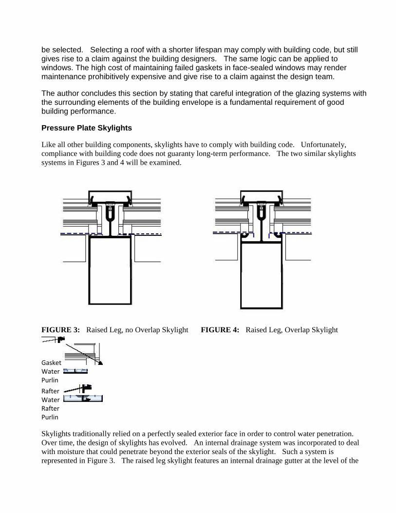
FIGURE 3: Raised Leg, no Overlap Skylight FIGURE 4: Raised Leg, Overlap Skylight
Gasket Water Purlin
Rafter Water Rafter Purlin
Skylights traditionally relied on a perfectly sealed exterior face in order to control water penetration.
Over time, the design of skylights has evolved. An internal drainage system was incorporated to deal
with moisture that could penetrate beyond the exterior seals of the skylight. Such a system is
represented in Figure 3. The raised leg skylight features an internal drainage gutter at the level of the
rafters and of the purlins. The dashed blue line represents the drainage path from the purlins of the
skylight into the rafters. Unfortunately, because the drainage gutters of the purlin and of the rafter are at
the same elevation, sealants and glazing tapes must be relied upon in order to ensure water tightness.
A vast improvement to the design of the skylight in Figure 4 is to raise the level of the bottom of the
drainage gutter of the purlin. Thus the joint between the purlin and the rafter is not exposed to water for
long periods of time.
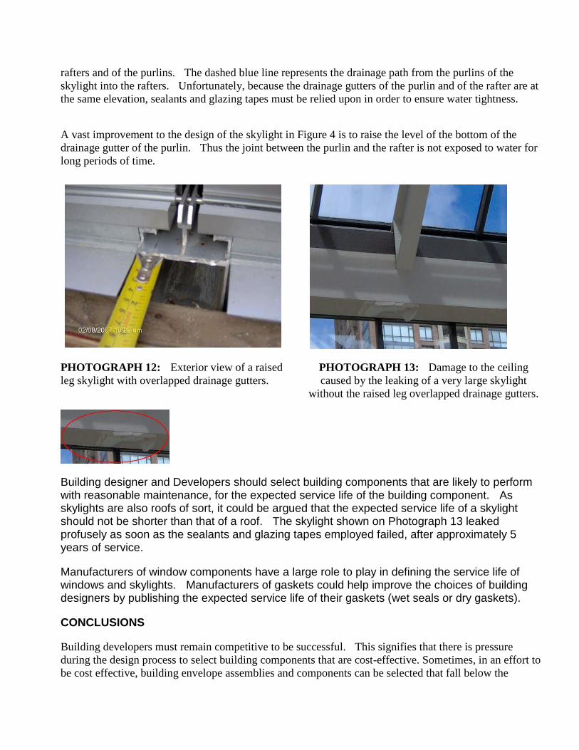
PHOTOGRAPH 12: Exterior view of a raised
leg skylight with overlapped drainage gutters.
PHOTOGRAPH 13: Damage to the ceiling
caused by the leaking of a very large skylight
without the raised leg overlapped drainage gutters.
Building designer and Developers should select building components that are likely to perform with reasonable maintenance, for the expected service life of the building component. As skylights are also roofs of sort, it could be argued that the expected service life of a skylight should not be shorter than that of a roof. The skylight shown on Photograph 13 leaked profusely as soon as the sealants and glazing tapes employed failed, after approximately 5 years of service.
Manufacturers of window components have a large role to play in defining the service life of windows and skylights. Manufacturers of gaskets could help improve the choices of building designers by publishing the expected service life of their gaskets (wet seals or dry gaskets).
CONCLUSIONS
Building developers must remain competitive to be successful. This signifies that there is pressure
during the design process to select building components that are cost-effective. Sometimes, in an effort to
be cost effective, building envelope assemblies and components can be selected that fall below the
standard of care required of prudent designers (and Developers). This can be the case even if the
requirements of the building code in effect at the time of the design are satisfied.
To compound the problem, there is the temptation among all sectors of the construction industry to
believe that a material, a building envelope assembly or system that complies with building code will
perform and be durable. This is not so.
The zone between the minimum standard laid out by building codes and the standard of care expected of
reasonable and prudent design professionals is filled with conflicts and uncertainty. Answers to questions
posed in this zone are usually not black or white but rather, shades of grey.
In British Columbia, the Government has mandated that residential buildings must be covered by a third
party warranty for a five year period from the date of building occupancy. The companies that offer
warranties must evaluate the risk associated with a building design. Where this risk is judged to be too
great, these companies introduce requirements that exceed the requirement of the existing building code.
The warranty companies are thus in a position to support the performance based requirements of the
building codes with their own prescriptive requirements that are based on the knowledge based provided
by past claims.
The Third Party Building Envelope Warranty may be a workable model for other jurisdictions as it
provides a method of harmonizing performance based requirements of codes with the prescriptive
knowledge gained from past experience.