building engineering services particular …...particular requirements 2 imperial college london...
TRANSCRIPT
Building Engineering Services
Particular Requirements
ICL BESPR-6:2016
Reference: EP01BESPR Date: 03/06/2016
Particular Requirements 1 Imperial College London (2015) Building Engineering Services
Reference: EP01BESPR Date: 03/06/2016
Publication History This section details the amendments issued since the first publication.
Version No. Revision Date Revision Title Brief Summary of Changes
ICLBESPR-1: 2014
November 2014
Particular Requirements
First Edition
ICLBESPR-2: 2015
February 2015
Particular Requirements
Addition of sections 20,22,24 and 27
ICLBESPR-3: 2015
April 2015
Particular Requirements
Addition of sections. Section re-numbering
ICLBESPR-4: 2015
September 2015
Particular Requirements
Addition of section 1 in the General section.
ICLBESPR-5: 2015
December 2015
Particular Requirements
Addition of section 19 in the Mechanical Section. Camera types updated in section 9.2.3.
ICLBESPR-6:2016
June 2016 Particular Requirements
Revisions to section 6 in the Mechanical Section.
Particular Requirements 2 Imperial College London (2015) Building Engineering Services
Reference: EP01BESPR Date: 03/06/2016
Table of Contents Introduction ............................................................................................................ 18
Purpose ................................................................................................................ 18
Components ......................................................................................................... 18
Deviations ............................................................................................................. 19
Electrical ................................................................................................................. 20
1 Small Power Supplies .................................................................................. 21
1.1 General .................................................................................................... 21
1.2 Workstations ............................................................................................ 21
1.3 Laboratories ............................................................................................. 22
1.4 Areas Containing Sinks or Basins ............................................................ 22
1.5 Freezer Supplies in Freezer Rooms ........................................................ 22
1.6 Labelling of Socket Outlets and Distribution Boards ................................ 22
1.7 Communications Wiring Centre (CWC) Rooms ....................................... 23
2 Lighting and Emergency Lighting .............................................................. 25
2.1 Design and Installation Principles ............................................................ 25
2.1.1 General .................................................................................................... 25
2.1.2 Light sources ............................................................................................ 27
2.1.3 Laboratories ............................................................................................. 27
2.1.4 Work Area Task Lighting .......................................................................... 28
2.2 Operation ................................................................................................. 28
2.2.1 General ................................................................................................. 28
2.2.2 Manual switching .................................................................................. 29
2.2.3 Automatic Control ................................................................................. 29
2.2.4 System Selection .................................................................................. 29
2.3 Evacuation Lighting .................................................................................. 31
2.3.1 Security Alert ............................................................................................ 31
2.4 Emergency Lighting ................................................................................. 32
2.5 Luminaire Installation ............................................................................... 32
2.6 External Lighting ...................................................................................... 32
2.7 Handover ................................................................................................. 33
Particular Requirements 3 Imperial College London (2015) Building Engineering Services
Reference: EP01BESPR Date: 03/06/2016
3 Earthing ........................................................................................................ 34
3.1 Introduction .............................................................................................. 34
3.2 HV System Earthing ................................................................................. 34
South Kensington Campus - 11kV System ....................................................... 34
3.2.1 .................................................................................................................. 34
3.2.2 .................................................................................................................. 34
3.2.3 .................................................................................................................. 35
3.2.4 .................................................................................................................. 35
3.2.5 .................................................................................................................. 35
3.2.6 .................................................................................................................. 35
3.2.7 .................................................................................................................. 35
3.2.8 .................................................................................................................. 35
South Kensington Campus - 6.6kV System ...................................................... 35
3.2.9 .................................................................................................................. 36
3.2.10 ................................................................................................................ 36
3.2.11 ................................................................................................................ 36
3.2.12 ................................................................................................................ 36
3.3 Transformer Enclosures ........................................................................... 36
3.3.1 .................................................................................................................. 36
3.3.2 .................................................................................................................. 36
3.4 LV Main Earths ........................................................................................ 36
3.4.1 .................................................................................................................. 37
3.4.2 .................................................................................................................. 37
3.4.3 .................................................................................................................. 37
3.4.4 .................................................................................................................. 37
3.4.5 .................................................................................................................. 37
3.5 LV Neutral Earths ..................................................................................... 37
3.5.1 .................................................................................................................. 37
3.5.2 .................................................................................................................. 37
3.5.3 .................................................................................................................. 38
3.6 Generator Earths ..................................................................................... 38
HV ..................................................................................................................... 38
Particular Requirements 4 Imperial College London (2015) Building Engineering Services
Reference: EP01BESPR Date: 03/06/2016
3.6.2 .................................................................................................................. 38
3.6.3 .................................................................................................................. 38
LV ...................................................................................................................... 38
3.6.4 .................................................................................................................. 38
3.6.5 .................................................................................................................. 38
3.6.6 .................................................................................................................. 38
3.7 Extraneous Metalwork and Other Earths ................................................. 39
3.7.1 .................................................................................................................. 39
3.7.2 .................................................................................................................. 39
3.7.3 .................................................................................................................. 39
3.8 Substation Main Earth Bars ..................................................................... 39
3.9 Other Campuses and Sites ...................................................................... 39
3.9.1 .................................................................................................................. 39
3.9.2 .................................................................................................................. 39
3.9.3 .................................................................................................................. 39
Appendix 3.10 Typical Substation Earthing Arrangement ..................................... 40
4 Design Criteria for Main Electrical Power Equipment ................................ 42
4.1 Main Electrical Equipment ....................................................................... 42
4.1.1 Introduction ........................................................................................... 42
4.1.2 HV Switchgear ......................................................................................... 42
4.1.3 Transformers ............................................................................................ 44
4.1.4 LV Switchgear .......................................................................................... 45
4.1.5 Cable Systems ......................................................................................... 46
4.1.6 Auxiliary Equipment ................................................................................. 46
4.1.7 Earthing .................................................................................................... 46
4.1.8 Switchgear Form of Separation ............................................................ 47
4.1.9 Data and Metering Cables .................................................................... 48
4.1.10 Switchroom Design ................................................................................ 48
4.1.11 Compliance ............................................................................................ 48
4.2 Separation Form for LV Panels ................................................................ 49
4.2.1 Purpose ................................................................................................ 49
4.2.2 Switchgear Form of Separation ............................................................ 49
Particular Requirements 5 Imperial College London (2015) Building Engineering Services
Reference: EP01BESPR Date: 03/06/2016
4.2.3 Data and Metering Cables .................................................................... 50
4.2.4 Switchroom Design ............................................................................... 50
4.2.5 Compliance ........................................................................................... 51
4.3 LV Electrical Panels rated up to 800A ...................................................... 51
4.3.1 Purpose and Scope .................................................................................. 51
4.3.2 Form of Separation .................................................................................. 51
4.3.3 Configurations .......................................................................................... 51
4.3.4 Outgoing devices ..................................................................................... 52
4.3.5 Metering ................................................................................................... 52
5 Electrical Load Calculations ............................................................................. 54
5.1 General ........................................................................................................... 54
6 Connection of Large Electrical Loads ......................................................... 55
6.1 Introduction ..................................................................................................... 55
6.2 Voltage Limits ................................................................................................. 55
6.3 Supply Security ............................................................................................... 56
6.4 Requirement for New Substations .................................................................. 56
7 Controls .............................................................................................................. 57
7.1 Introduction ..................................................................................................... 57
7.2 General ........................................................................................................... 57
7.2.1 Introduction .............................................................................................. 57
7.2.2 .................................................................................................................. 58
7.2.3 .................................................................................................................. 58
7.2.4 .................................................................................................................. 58
7.2.5 .................................................................................................................. 58
7.2.6 .................................................................................................................. 58
7.2.7 .................................................................................................................. 58
7.2.8 .................................................................................................................. 58
7.2.9 .................................................................................................................. 59
7.2.10 ................................................................................................................ 59
7.2.11 ................................................................................................................ 59
7.2.12 ................................................................................................................ 59
7.2.13 ................................................................................................................ 59
Particular Requirements 6 Imperial College London (2015) Building Engineering Services
Reference: EP01BESPR Date: 03/06/2016
7.3 Control Panels ......................................................................................... 59
7.3.1 .................................................................................................................. 59
7.3.2 .................................................................................................................. 60
7.3.3 .................................................................................................................. 60
7.3.4 .................................................................................................................. 60
7.3.5 .................................................................................................................. 60
7.3.6 .................................................................................................................. 60
7.3.7 .................................................................................................................. 60
7.3.8 .................................................................................................................. 60
7.3.9 .................................................................................................................. 61
7.3.10 ................................................................................................................ 61
7.3.11 ................................................................................................................ 61
7.3.12 ................................................................................................................ 61
7.3.13 ................................................................................................................ 61
7.3.14 ................................................................................................................ 61
7.3.15 ................................................................................................................ 61
7.3.16 ................................................................................................................ 62
7.3.17 ................................................................................................................ 62
7.3.18 ................................................................................................................ 62
7.4 Outstations ..................................................................................................... 62
7.4.1 .................................................................................................................. 62
7.4.2 .................................................................................................................. 62
7.4.3 .................................................................................................................. 63
7.4.4 .................................................................................................................. 63
7.4.5 .................................................................................................................. 63
7.4.6 .................................................................................................................. 63
7.4.7 .................................................................................................................. 63
7.4.8 .................................................................................................................. 63
7.4.9 .................................................................................................................. 63
7.5 IQ Engineering ......................................................................................... 64
7.5.1 .................................................................................................................. 64
7.5.2 .................................................................................................................. 64
Particular Requirements 7 Imperial College London (2015) Building Engineering Services
Reference: EP01BESPR Date: 03/06/2016
7.5.3 .................................................................................................................. 64
7.5.4 .................................................................................................................. 64
7.5.5 .................................................................................................................. 64
7.5.6 .................................................................................................................. 64
7.6 Supervisor Engineering ............................................................................ 65
7.6.1 .................................................................................................................. 65
7.6.2 .................................................................................................................. 65
7.6.3 .................................................................................................................. 65
7.6.4 .................................................................................................................. 65
7.6.5 .................................................................................................................. 65
7.6.6 .................................................................................................................. 66
7.6.7 .................................................................................................................. 66
7.6.8 .................................................................................................................. 66
7.7 Additions to the Existing System .............................................................. 66
7.7.1 .................................................................................................................. 66
7.7.2 .................................................................................................................. 66
7.7.3 .................................................................................................................. 67
7.7.4 .................................................................................................................. 67
7.7.5 .................................................................................................................. 67
7.7.6 .................................................................................................................. 67
7.7.7 .................................................................................................................. 67
7.7.8 .................................................................................................................. 67
7.7.9 .................................................................................................................. 67
7.7.10 ................................................................................................................ 68
7.7.11 ................................................................................................................ 68
7.7.12 ................................................................................................................ 68
7.8 Field Wiring & Equipment ........................................................................ 68
7.8.1 .................................................................................................................. 68
7.8.2 .................................................................................................................. 68
7.8.3 .................................................................................................................. 69
7.8.4 .................................................................................................................. 69
7.8.5 .................................................................................................................. 69
Particular Requirements 8 Imperial College London (2015) Building Engineering Services
Reference: EP01BESPR Date: 03/06/2016
7.8.6 .................................................................................................................. 69
7.8.7 .................................................................................................................. 69
7.8.8 .................................................................................................................. 69
7.9 Alarm Reporting ....................................................................................... 69
7.9.1 .................................................................................................................. 69
7.9.2 .................................................................................................................. 70
7.9.3 .................................................................................................................. 70
7.9.4 .................................................................................................................. 70
7.10 Metering ................................................................................................... 70
7.10.1 ................................................................................................................ 70
7.11 Lighting ......................................................................................................... 70
7.11.1 ................................................................................................................ 70
7.11.2 ................................................................................................................ 70
7.11.3 ................................................................................................................ 71
7.11.4 ................................................................................................................ 71
7.11.5 ................................................................................................................ 71
7.12 Commissioning / Witnessing .................................................................... 71
7.12.1 ................................................................................................................ 71
7.12.2 ................................................................................................................ 71
7.12.3 ................................................................................................................ 71
7.12.4 ................................................................................................................ 72
7.13 Documentation ......................................................................................... 72
7.13.1 ................................................................................................................ 72
7.13.2 ................................................................................................................ 72
7.13.3 ................................................................................................................ 72
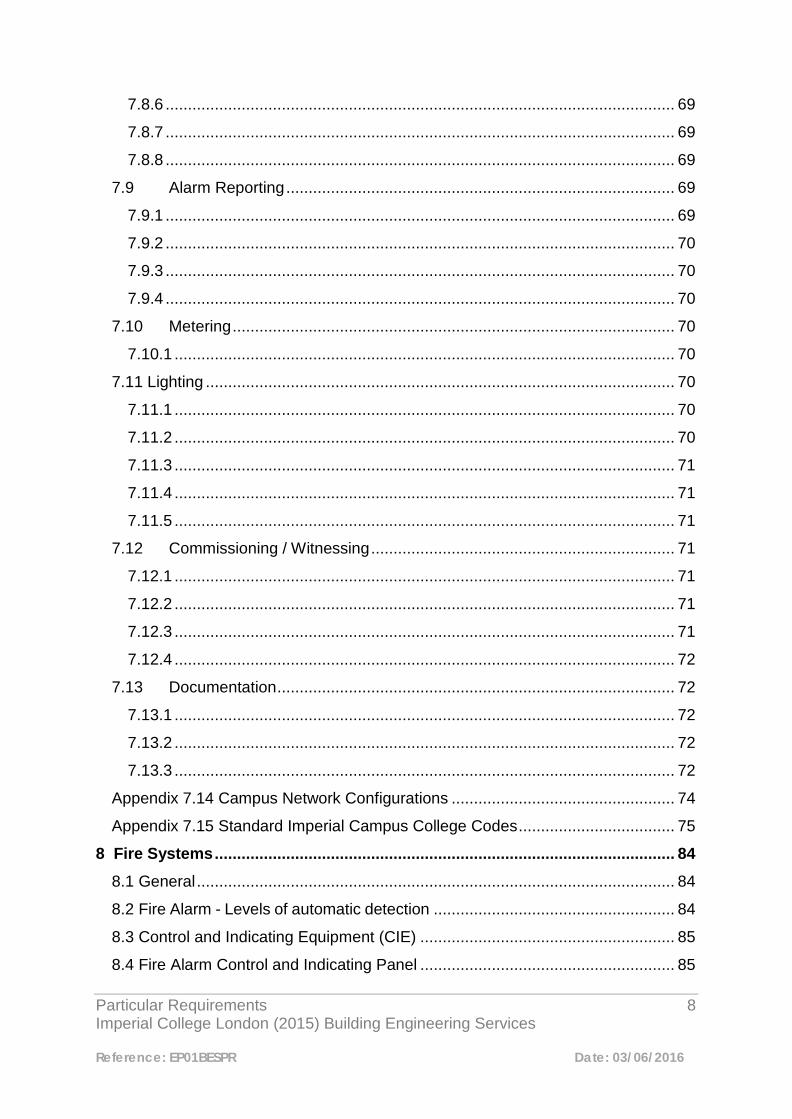
Appendix 7.14 Campus Network Configurations .................................................. 74
Appendix 7.15 Standard Imperial Campus College Codes ................................... 75
8 Fire Systems ....................................................................................................... 84
8.1 General ........................................................................................................... 84
8.2 Fire Alarm - Levels of automatic detection ...................................................... 84
8.3 Control and Indicating Equipment (CIE) ......................................................... 85
8.4 Fire Alarm Control and Indicating Panel ......................................................... 85
Particular Requirements 9 Imperial College London (2015) Building Engineering Services
Reference: EP01BESPR Date: 03/06/2016
8.5 Conventional Systems .................................................................................... 85
8.6 Standby Supplies (Battery Back-up) ............................................................... 85
8.7 Devices for use in Addressable Systems ........................................................ 85
8.7.1 Point Detectors ......................................................................................... 85
8.7.2 Manual Call Points ................................................................................... 86
8.7.3 Input/Output Units .................................................................................... 86
8.7.4 Beam Detectors ....................................................................................... 86
8.7.5 Aspirating Fire Detection .......................................................................... 86
8.8 Sounders ........................................................................................................ 87
8.9 Visual Alarm Devices ...................................................................................... 87
8.9.1 Beacons ................................................................................................... 87
8.10 Magnetic Door Retainers .............................................................................. 87
8.11 Plant Override Test Switch ........................................................................... 87
8.13 Speech Dialler .............................................................................................. 87
8.14 Vibrating Pillows ........................................................................................... 88
8.15 Vibrating Paging System .............................................................................. 88
8.16 Fire Alarm/Access Control Interface .............................................................. 88
8.17 Connection and Commissioning ................................................................... 89
8.18 Record Drawings .......................................................................................... 89
8.19 Log Books ..................................................................................................... 90
8.20 Temporary Fire Detection ............................................................................. 90
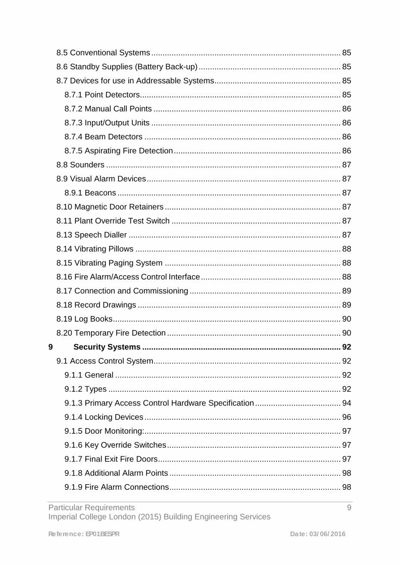
9 Security Systems ........................................................................................ 92
9.1 Access Control System ................................................................................... 92
9.1.1 General .................................................................................................... 92
9.1.2 Types ....................................................................................................... 92
9.1.3 Primary Access Control Hardware Specification ...................................... 94
9.1.4 Locking Devices ....................................................................................... 96
9.1.5 Door Monitoring: ....................................................................................... 97
9.1.6 Key Override Switches ............................................................................. 97
9.1.7 Final Exit Fire Doors ................................................................................. 97
9.1.8 Additional Alarm Points ............................................................................ 98
9.1.9 Fire Alarm Connections ............................................................................ 98
Particular Requirements 10 Imperial College London (2015) Building Engineering Services
Reference: EP01BESPR Date: 03/06/2016
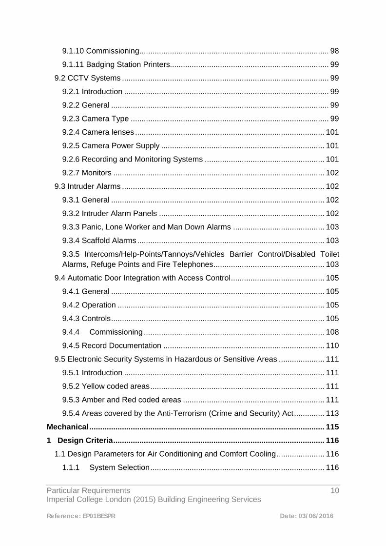
9.1.10 Commissioning ....................................................................................... 98
9.1.11 Badging Station Printers......................................................................... 99
9.2 CCTV Systems ............................................................................................... 99
9.2.1 Introduction .............................................................................................. 99
9.2.2 General .................................................................................................... 99
9.2.3 Camera Type ........................................................................................... 99
9.2.4 Camera lenses ....................................................................................... 101
9.2.5 Camera Power Supply ........................................................................... 101
9.2.6 Recording and Monitoring Systems ....................................................... 101
9.2.7 Monitors ................................................................................................. 102
9.3 Intruder Alarms ............................................................................................. 102
9.3.1 General .................................................................................................. 102
9.3.2 Intruder Alarm Panels ............................................................................ 102
9.3.3 Panic, Lone Worker and Man Down Alarms .......................................... 103
9.3.4 Scaffold Alarms ...................................................................................... 103
9.3.5 Intercoms/Help-Points/Tannoys/Vehicles Barrier Control/Disabled Toilet Alarms, Refuge Points and Fire Telephones ................................................... 103
9.4 Automatic Door Integration with Access Control ........................................... 105
9.4.1 General .................................................................................................. 105
9.4.2 Operation ............................................................................................... 105
9.4.3 Controls .................................................................................................. 105
9.4.4 Commissioning ................................................................................... 108
9.4.5 Record Documentation .......................................................................... 110
9.5 Electronic Security Systems in Hazardous or Sensitive Areas ..................... 111
9.5.1 Introduction ............................................................................................ 111
9.5.2 Yellow coded areas ................................................................................ 111
9.5.3 Amber and Red coded areas ................................................................. 111
9.5.4 Areas covered by the Anti-Terrorism (Crime and Security) Act .............. 113
Mechanical ............................................................................................................ 115
1 Design Criteria ................................................................................................. 116
1.1 Design Parameters for Air Conditioning and Comfort Cooling ...................... 116
1.1.1 System Selection ................................................................................ 116
Particular Requirements 11 Imperial College London (2015) Building Engineering Services
Reference: EP01BESPR Date: 03/06/2016
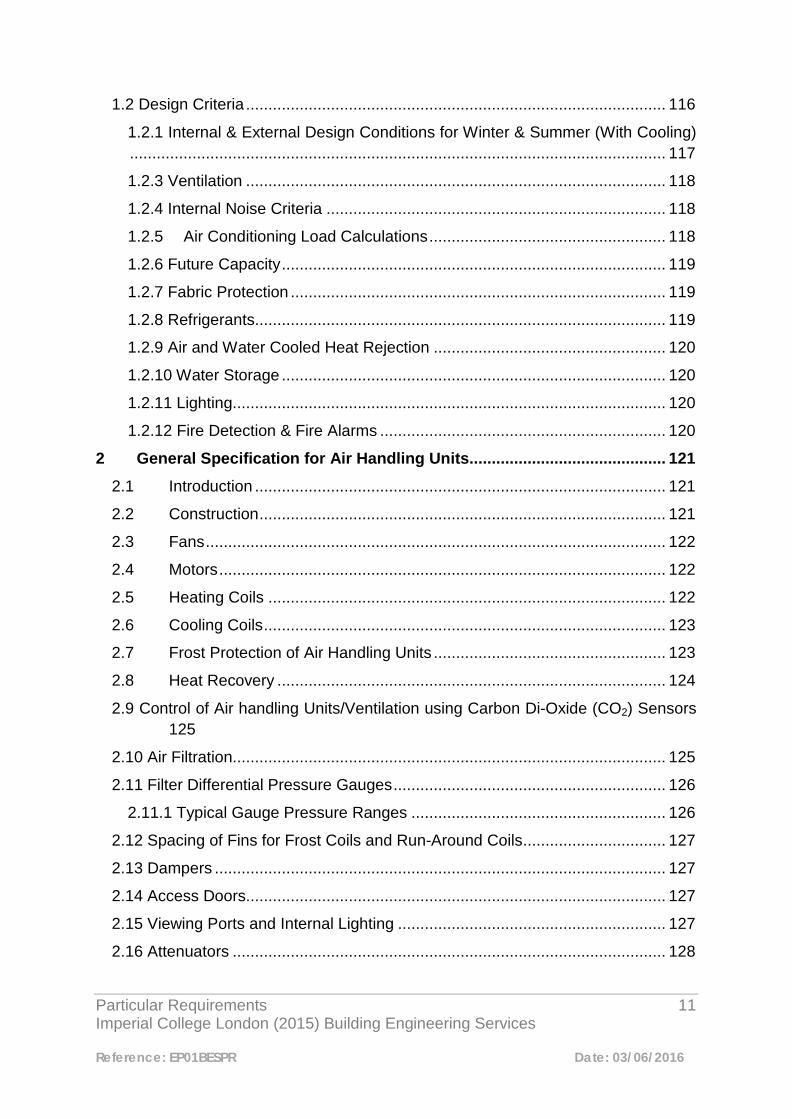
1.2 Design Criteria .............................................................................................. 116
1.2.1 Internal & External Design Conditions for Winter & Summer (With Cooling) ........................................................................................................................ 117
1.2.3 Ventilation .............................................................................................. 118
1.2.4 Internal Noise Criteria ............................................................................ 118
1.2.5 Air Conditioning Load Calculations ..................................................... 118
1.2.6 Future Capacity ...................................................................................... 119
1.2.7 Fabric Protection .................................................................................... 119
1.2.8 Refrigerants ............................................................................................ 119
1.2.9 Air and Water Cooled Heat Rejection .................................................... 120
1.2.10 Water Storage ...................................................................................... 120
1.2.11 Lighting................................................................................................. 120
1.2.12 Fire Detection & Fire Alarms ................................................................ 120
2 General Specification for Air Handling Units............................................ 121
2.1 Introduction ............................................................................................ 121
2.2 Construction ........................................................................................... 121
2.3 Fans ....................................................................................................... 122
2.4 Motors .................................................................................................... 122
2.5 Heating Coils ......................................................................................... 122
2.6 Cooling Coils .......................................................................................... 123
2.7 Frost Protection of Air Handling Units .................................................... 123
2.8 Heat Recovery ....................................................................................... 124
2.9 Control of Air handling Units/Ventilation using Carbon Di-Oxide (CO2) Sensors 125
2.10 Air Filtration................................................................................................. 125
2.11 Filter Differential Pressure Gauges ............................................................. 126
2.11.1 Typical Gauge Pressure Ranges ......................................................... 126
2.12 Spacing of Fins for Frost Coils and Run-Around Coils ................................ 127
2.13 Dampers ..................................................................................................... 127
2.14 Access Doors .............................................................................................. 127
2.15 Viewing Ports and Internal Lighting ............................................................ 127
2.16 Attenuators ................................................................................................. 128
Particular Requirements 12 Imperial College London (2015) Building Engineering Services
Reference: EP01BESPR Date: 03/06/2016
2.17 Condensate Traps ...................................................................................... 128
2.18 Eurovent Certification ................................................................................. 128
Appendix 2.19 Arrangement of typical AHU ....................................................... 129
Appendix 2.20 AHU Condensate Trap Configuration ......................................... 130
Appendix 2.21 Typical Steam & Condensate Connection to Air Handling Unit Heater Battery .................................................................................................... 131
3 Pipework and Ancillaries .......................................................................... 133
3.1 Pipework Materials and Jointing Methods .................................................... 133
3.1.1 Introduction ............................................................................................ 133
3.1.2 Table of Standard Pipework Materials ................................................... 133
3.1.3 Soil, Waste, Vent & Rainwater Systems ................................................ 134
3.1.4 Pipe Jointing Methods ............................................................................ 134
3.2 Commissioning Sets for Installation on CHW, LTHW & MTHW Heating ...... 135
3.2.1 General .................................................................................................. 135
3.3 Venting of Air in Pipework ............................................................................. 136
3.3.1 Manual Air Vents .................................................................................... 136
3.3.2 Automatic Air Vents ................................................................................ 137
4 Pump Sets and Inverter Drives ................................................................ 138
4.1 Pump Sets .................................................................................................... 138
4.2 Inverters ........................................................................................................ 138
Appendix 4.3 Typical Pump Set Arrangement .................................................... 139
5 Pressurisation Units for LTHW Heating, CHW & Process Cooling ....... 140
5.1 Introduction ............................................................................................ 140
5.2 Unit Selection ......................................................................................... 140
5.3 Unit Specification ................................................................................... 141
6 Hot and Cold Water Services ..................................................................... 142
6.1 Central Systems..................................................................................... 142
6.2 Minimising Risk of Legionnaires Disease ............................................... 142
6.3 Connection into Existing Hot and Cold Water Service Infrastructure ..... 142
6.4 Secondary Circulation of Hot Water Services ........................................ 142
6.5 Stand-Alone Point-of-Use Hot Water Heaters .............................................. 143
6.6 Cold Water Storage Tanks ........................................................................... 143
Particular Requirements 13 Imperial College London (2015) Building Engineering Services
Reference: EP01BESPR Date: 03/06/2016
6.7 Cold Water Pumping Equipment ................................................................... 143
6.8 System Design .............................................................................................. 144
6.9 Hot and Cold Water Taps ............................................................................. 144
6.10 Thermostatic Mixing Valves ........................................................................ 144
6.11 Hot and Cold Water Services in Laboratories ............................................. 144
7 Condense Drains ....................................................................................... 146
7.1 General ......................................................................................................... 146
8 Thermostatic Radiator Valves (TRV’s) and Radiator Lockshield Valves 147
8.1 Valve Body ................................................................................................... 147
8.2 Sensor Heads ............................................................................................... 147
8.3 Radiator Lockshield (Return) Valves ............................................................ 148
8.4 Maintenance of Thermostatic Radiator Valves ............................................. 148
9 Steam System Components ..................................................................... 149
9.1 Connection into Existing Steam Mains ......................................................... 149
9.2 Isolating Valves for use on Steam Mains ...................................................... 149
9.3 Pressure Reducing Valves for use on Steam Mains ..................................... 149
9.4 Steam Trap Sets ........................................................................................... 150
9.5 Steam Meters ............................................................................................... 151
Appendix 9.6 Steam Pressure Reducing Set ...................................................... 152
Appendix 9.7 Typical Arrangement of Steam Trap Sets ..................................... 154
Appendix 9.8 Detail of Steam Main Drainage Point ............................................ 156
10 Plant Room Drainage Gullies ................................................................... 158
10.1 General .................................................................................................. 158
11 Constant Temperature Heating for Primary Air Re-Heat & Zonal Re-Heat 160
11.1 General ....................................................................................................... 160
12 Fan Coil Units ............................................................................................ 162
12.1 Introduction ............................................................................................ 162
12.2 Construction ........................................................................................... 162
12.3 Fans ....................................................................................................... 162
12.4 Motors .................................................................................................... 163
12.5 Heating & Cooling Coils .............................................................................. 163
Particular Requirements 14 Imperial College London (2015) Building Engineering Services
Reference: EP01BESPR Date: 03/06/2016
12.6 Filters .......................................................................................................... 163
12.7 Controls ................................................................................................. 163
12.7.1 Two-Port Valves ................................................................................... 163
12.7.2 Four-Port Control Valves ...................................................................... 163
12.7.3 BEMS Control of Fan Coil Units ........................................................... 164
12.8 Fan Speed Selection .................................................................................. 164
12.9 Occupancy Control of Fan Coil Units in Cellular Areas ............................... 164
13 Process Cooling Systems ........................................................................ 165
13.1 Option Appraisal ......................................................................................... 165
13.2 Central System Details (Option 2) .............................................................. 166
13.2.1 General ................................................................................................ 166
13.2.2 Plate Heat Exchanger .......................................................................... 166
13.2.3 Pressurisation Unit ............................................................................... 167
13.2.4 Air Venting ............................................................................................ 167
13.2.5 Circulating Pump .................................................................................. 167
13.2.6 Pipework and Fittings ........................................................................... 167
13.2.7 Water Treatment .................................................................................. 168
13.2.8 Final Connections to Equipment .......................................................... 168
13.2.9 Controls ................................................................................................ 168
13.2.10 Flushing, Testing and Commissioning ............................................... 168
Appendix 13.3 Laser Process Cooling Typical Schematic Arrangement ........... 169
Appendix 13.4 Laser Equipment Data Sheet ...................................................... 171
14 Chillers ......................................................................................................... 173
14.1 General ....................................................................................................... 173
14.2 Additional Safety Measures ........................................................................ 173
14.3 Approved Suppliers .................................................................................... 173
14.4 Plant Maintenance ...................................................................................... 174
15 Remote Control of Ventilation Systems in Fire Condition....................... 177
15.1 General .................................................................................................. 177
16 Thermal Insulation and Finishes to Ductwork and Pipework .................. 178
16.1 Thermal Insulating Materials .................................................................. 178
16.2 Pipework Insulation ..................................................................................... 180
Particular Requirements 15 Imperial College London (2015) Building Engineering Services
Reference: EP01BESPR Date: 03/06/2016
16.3 Steam Meters and Heat Meters .................................................................. 182
16.4 Valve Boxes and Removable Insulation Jackets ........................................ 182
16.5 Pipe Ends ................................................................................................... 183
16.6 Ductwork Insulation .................................................................................... 183
16.6.1 Internal Areas ....................................................................................... 183
16.6.2 External Areas ...................................................................................... 183
16.6.3 Vapour Barriers .................................................................................... 183
16.7 Service Identification ................................................................................... 183
17 Toilet Ventilation Systems......................................................................... 185
17.1 Toilet Extract .......................................................................................... 185
17.2 Toilet Supply .......................................................................................... 185
17.3 Toilet Ventilation Rates .......................................................................... 186
17.4 Toilet Ventilation Plant Time Control ...................................................... 186
18 Plant Identification ..................................................................................... 187
18.1 Plant and Equipment Identification Labels .................................................. 187
18.2 Equipment Asset Codes ............................................................................. 187
18.3 Plant and Equipment to be labeled ............................................................. 188
18.4 Required Level of Labeling Information ...................................................... 188
19 Hot and Cold Water Services ....................................................................... 190
19.1 Central Systems ......................................................................................... 190
19.2 Minimising Risk of Legionnaires Disease ................................................... 190
19.3 Connection into Existing Hot and Cold Water Service Infrastructure .......... 190
19.4 Secondary Circulation of Hot Water Services ............................................. 190
19.5 Stand-Alone Point-of-Use Hot Water Heaters............................................. 191
19.6 Cold Water Storage Tanks.......................................................................... 191
19.7 Cold Water Pumping Equipment ................................................................. 191
19.8 System Design ............................................................................................ 192
19.9 Hot and Cold Water Taps ........................................................................... 192
19.10 Thermostatic Mixing Valves ...................................................................... 192
19.11 Hot and Cold Water Services in Laboratories ........................................... 192
General .................................................................................................................. 194
1 Metering ............................................................................................................ 195
Particular Requirements 16 Imperial College London (2015) Building Engineering Services
Reference: EP01BESPR Date: 03/06/2016
1.1 Introduction ............................................................................................ 195
1.2 General .................................................................................................. 195
1.2.1 Metered services ................................................................................ 195
1.2.2 Summary and general metering requirement ......................................... 195
1.3 Mechanical Systems ..................................................................................... 197
1.3.1 Saturated Steam .................................................................................... 197
1.3.2 LTHW, MPHW & CHW ........................................................................... 197
1.3.3 Hot Water Services (HWS) ..................................................................... 197
1.3.4 Domestic cold water ............................................................................... 198
1.3.5 Gas Meters ............................................................................................. 198
1.4 Electrical Systems ........................................................................................ 198
1.4.1 Main incoming Panels ............................................................................ 198
1.4.2 General Electrical Circuits ...................................................................... 199
1.4.3 Alternative Meters (to the above) ........................................................... 200
1.5 Connectivity .................................................................................................. 200
1.5.1 General Connectivity .............................................................................. 200
1.5.2 Mechanical Systems .............................................................................. 200
1.5.3 Electrical Systems .................................................................................. 201
1.6 Strategy drawings; Responsibilities & Demarcations .................................... 205
1.6.1 Designer ............................................................................................. 205
1.6.2 Contractor ........................................................................................... 205
Appendix 1.7 Approvals Procedure .................................................................... 206
Appendix 1.8 Example of Electrical Meter Strategy ............................................ 208
Appendix 1.9 Example of Mechanical Meter Strategy ........................................ 209
Appendix 1.10 Metering Schedule ...................................................................... 211
Appendix 1.11 SIPe master register ................................................................... 213
Appendix 1.12 Electrical Warning Labels ........................................................... 214
2 Equality Act 2010 Electronic Systems ............................................................ 215
2.1 Access and Egress - Access Control and Automatic Doors ......................... 215
2.1.1 Introduction ............................................................................................ 215
2.1.2 General .................................................................................................. 215
2.1.3 Door types .............................................................................................. 215
Particular Requirements 17 Imperial College London (2015) Building Engineering Services
Reference: EP01BESPR Date: 03/06/2016
2.1.4 Access Control Readers ........................................................................ 216
2.1.5 Turnstiles................................................................................................ 216
2.1.6 Optical Turnstiles ................................................................................... 216
2.1.7 Half Height Fixed Arm Turnstiles ............................................................ 217
2.1.8 Speedgates ............................................................................................ 217
2.1.9 Full Height Turnstiles ............................................................................. 218
2.1.10 Tailgate Detection Devices................................................................... 218
2.1.11 College Preferences ............................................................................. 219
2.2 Fire Alarms ................................................................................................... 219
2.2.1 General .................................................................................................. 219
2.2.2 Emergency Messaging Systems ............................................................ 221
2.2.3 College Preferences ............................................................................... 221
2.3 Refuge Areas ................................................................................................ 221
2.3.1 Emergency Voice Communication Systems ........................................... 221
2.4 Signage ........................................................................................................ 222
2.1 General ..................................................................................................... 222
2.4.2 College Preferences ............................................................................... 222
2.5 Sanitary Accommodation ....................................................................... 223
2.5.1 Emergency Assistance Alarm ............................................................. 223
2.5.2 Fire Alarms ............................................................................................. 223
2.5.3 College Preferences ............................................................................... 223

Particular Requirements 18 Imperial College London (2015) Building Engineering Services
Reference: EP01BESPR Date: 03/06/2016
Introduction Purpose The purpose of this document is to provide information regarding Imperial College London’s Particular Requirements for Building Engineering Services. This document shall be read in conjunction with all relevant British Standards and Codes of Practice; it does not seek to replace industry-standard design guidance or practice. It is intended to provide the College’s particular requirements, which are to be used as the basis of all building engineering services. Although this document describes particular requirements it is to be read in conjunction with all other Imperial supporting documentation such as Health and Safety, Operational and/or User requirements, standards and/ or codes of practices. These can be found on the Colleges Website or by contacting the relevant Imperial department. All Approved Suppliers will be expected to comply with the Particular Requirements when preparing any information for building engineering services works Components The choice of components for building engineering services designs are to be selected with particular reference to their ease of use, frequency of maintenance, ease of maintenance, ease of upgrading or renewal and their ability to offer future flexibility and adaptability. All building engineering services components shall be selected where available from Manufacturers listed within the “Imperial Approved Suppliers Component list”. Installation techniques, material selections, services installations and finishes shall all offer good value for money, and offer a solution that provides minimal environmental impact, be energy efficient, good life expectancy and low maintenance as well as conforming to any manufacturer’s requirements.
Particular Requirements 19 Imperial College London (2015) Building Engineering Services
Reference: EP01BESPR Date: 03/06/2016
Deviations Should designers and/or providers find it necessary to incorporate alternative standards or requirements to those stated within the following document then approval shall be sought in writing from the Engineering Manager by way of an “Exception Report B - Mechanical & Electrical”. Designers and/or providers of building construction works will be required to justify and demonstrate, with written documentation, that the alternative proposals will provide equivalent or better performance, result in the same or improved whole life costing and be of equal or better value.

Particular Requirements 20 Imperial College London (2015) Building Engineering Services
Reference: EP01BESPR Date: 03/06/2016
Electrical
Particular Requirements 21 Imperial College London (2015) Building Engineering Services
Reference: EP01BESPR Date: 03/06/2016
1
Small Power Supplies 1.1 General When designing the number of socket outlets to be connected to individual circuits, due account shall be taken of the nature of the work to be undertaken in the area(s) served, and the possible disruption that would result from a single circuit failure or interruption. On no account shall the number of sockets served from a single ring circuit protected by a 32 amp protective device, exceed 10 No. single or 2 gang outlets, subject also to ensuring that the circuit voltage drop does not exceed the required limit. 1.2 Workstations The number of socket outlets serving a single office workstation to be agreed with the end user, subject to a minimum of 2 No.2 gang switched socket outlets where the end user has no specific requirements. The socket outlets are to be presented in such a manner as to be easily accessible to the workstation user. All socket outlets to be double pole switched. Where a desk management system is proposed, this shall comply with the current edition of BS 6396: (Electrical systems in office furniture and office screens –Specification). Subject to a maximum of eight, the number of fused connection units to be connected to a single 16 amp or 20 amp radial circuit shall be such that the simultaneous starting current of equipment connected to the circuit shall not cause the circuit protective device to operate.

Particular Requirements 22 Imperial College London (2015) Building Engineering Services
Reference: EP01BESPR Date: 03/06/2016
1.3 Laboratories Socket outlets intended for use on laboratory benches (that is mounted on or above the bench) shall be arranged such that circuits serving one side of each bench run are connected to the same phase. 1.4 Areas Containing Sinks or Basins Socket outlets proposed to be located in an environment where it is considered that there is a significant risk of accidental contact with wet services, shall comply with the following arrangements as necessary to reduce that risk to the minimum:-
• Where sinks or basins are present, no socket outlets shall be positioned less than 500mm from the closest edge of a sink or basin.
• Socket outlet circuits to be protected by a residual current device.
1.5 Freezer Supplies in Freezer Rooms Freezers that are provided for research or process based function are to be served from circuits connected to a dedicated distribution board, positioned local to, or preferably within the area in which the freezers are located. In order to limit the number of freezers that may be lost as a result of a distribution board failure, no more than 20 No. freezers are to be connected to a single distribution board. Freezers are to be served from radial circuits serving not more than two freezers in total. The distribution board shall be sized to accommodate the known freezer load, and include spare capacity for future expansion based on a minimum allowance of 25%, rising to 100% according to the space available for additional freezers to be installed. Circuit protective devices and circuit arrangements, to be selected to ensure that circuit protective devices do not operate as a result of freezers starting simultaneously i.e. as in the case of a supply resumption following a power failure. 1.6 Labelling of Socket Outlets and Distribution Boards All socket outlets are to be labeled with the circuit reference to uniquely identify where they are fed from. Every distribution board should have all the outgoing circuits labelled using a DYMO labelling machine and placed in the space provided within the board. This labelling does not replace the issue of providing a distribution board schedule in accordance with the recommendations of the IEE wiring

Particular Requirements 23 Imperial College London (2015) Building Engineering Services
Reference: EP01BESPR Date: 03/06/2016
regulations. The schedule should be laminated and glued to the inside door of the distribution board. 1.7 Communications Wiring Centre (CWC) Rooms Each CWC room shall be provided with a dedicated distribution board, complete with type C miniature circuit breakers (MCB’s). The final circuit provision form this distribution board shall be as follows (Note: ICT as referred to below shall mean Imperial College London, Information and Communication Technology Department): Designer and/or contractor:
• 2No. 16amp unswitched BS EN 60309-1 (BS 4343) socket outlets per cabinet. (Location to be confirmed by ICT). Socket outlets to be as manufactured by MK Electric, selected from their `Commando` range
• 1No. 13amp 2 gang switched socket outlet. (Height and location to be agreed with ICT).
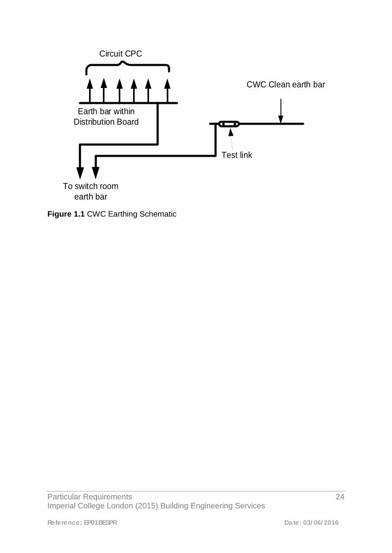
• A clean earth bar complete with a test link connection. Number of connections available to equal number of cabinets installed plus an allowance for future cabinets, as agreed with ICT.
• All cabinets to have their frame connected to the clear earth bar • All socket outlets to be labelled with a circuit reference. • Warning labels noting the presence of a clean earth system (in accordance
with BS 7671). • 1No. 63 amp switched interlocked BS EN 60309-1 (BS 4343) socket outlet to
be provided per router location (it is recommended that this supply is served from the distribution board in the CWC room). Socket outlets to be as manufactured by MK Electric, selected from their `Commando` range.
Data wiring cabling contractor:
• 2No. power track bus-bars per cabinet, switched, with 10No. 13amp socket outlets on each, (as Mayflex 10 way EN 60309 (BS4343) vertical power strip, 16amp) or equivalent.
The illustration in Figure 1.1 is an example of an earthing connection within the CWC room.
Particular Requirements 24 Imperial College London (2015) Building Engineering Services
Reference: EP01BESPR Date: 03/06/2016
Earth bar within Distribution Board
Circuit CPC
To switch room earth bar
Test link
CWC Clean earth bar
Figure 1.1 CWC Earthing Schematic

Particular Requirements 25 Imperial College London (2015) Building Engineering Services
Reference: EP01BESPR Date: 03/06/2016
2
Lighting and Emergency Lighting 2.1 Design and Installation Principles 2.1.1 General The design, equipment selection and installation of all lighting and emergency lighting systems shall be:
• Sourced from one of our 4 approved lighting suppliers • Capable of delivering the required level of illumination • Energy efficient in its operation • Offer durability and reliability in its operation, at a competitive cost • Complimentary to the aesthetics of the space in which it is installed, both in
appearance and in its function All lighting schemes shall be designed to create a suitably illuminated task area and ambient lighting of the surrounding area. Lighting levels as set out in Table 2.1 shall be applied to all College projects. In all other respects, the requirements of the CIBSE Code for Lighting, and associated CIBSE Lighting Guides, are to be applied to the design of lighting schemes. Lighting calculations are to be undertaken in order that the appropriate light source, type and quantity thereof are used. Presence detectors shall be of either passive Infra-red or microwave type and where appropriate shall incorporate a photo cell to enable maximum utilisation of daylight harvesting. Presence detectors shall be selected from the following manufacturers:-
Any of the College’s approved lighting suppliers
Particular Requirements 26 Imperial College London (2015) Building Engineering Services
Reference: EP01BESPR Date: 03/06/2016
BEG Luxomat Ex-Or
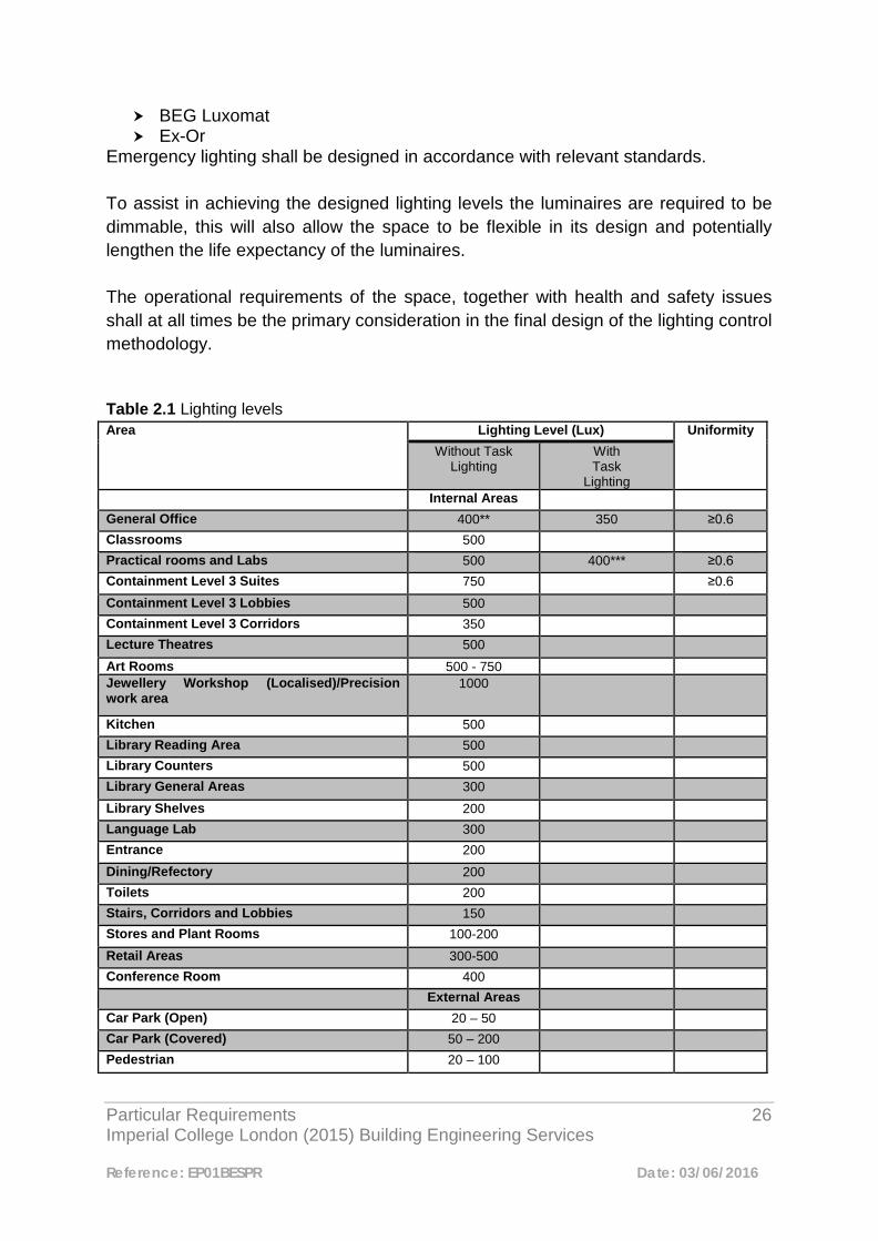
Emergency lighting shall be designed in accordance with relevant standards. To assist in achieving the designed lighting levels the luminaires are required to be dimmable, this will also allow the space to be flexible in its design and potentially lengthen the life expectancy of the luminaires. The operational requirements of the space, together with health and safety issues shall at all times be the primary consideration in the final design of the lighting control methodology. Table 2.1 Lighting levels Area Lighting Level (Lux) Uniformity
Without Task Lighting
With Task
Lighting Internal Areas
General Office 400** 350 ≥0.6 Classrooms 500 Practical rooms and Labs 500 400*** ≥0.6 Containment Level 3 Suites 750 ≥0.6 Containment Level 3 Lobbies 500 Containment Level 3 Corridors 350 Lecture Theatres 500 Art Rooms 500 - 750 Jewellery Workshop (Localised)/Precision work area
1000
Kitchen 500 Library Reading Area 500 Library Counters 500 Library General Areas 300 Library Shelves 200 Language Lab 300 Entrance 200 Dining/Refectory 200 Toilets 200 Stairs, Corridors and Lobbies 150 Stores and Plant Rooms 100-200 Retail Areas 300-500 Conference Room 400 External Areas Car Park (Open) 20 – 50 Car Park (Covered) 50 – 200 Pedestrian 20 – 100
Particular Requirements 27 Imperial College London (2015) Building Engineering Services
Reference: EP01BESPR Date: 03/06/2016
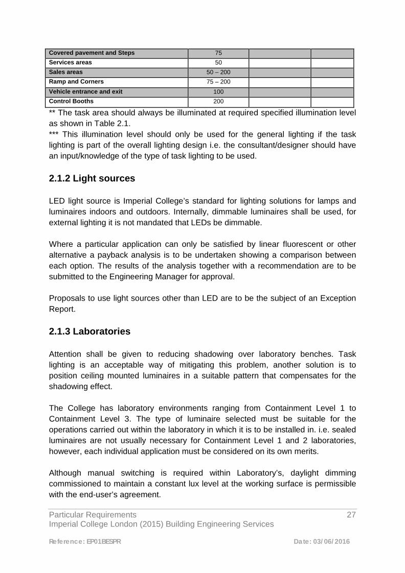
Covered pavement and Steps 75 Services areas 50 Sales areas 50 – 200 Ramp and Corners 75 – 200 Vehicle entrance and exit 100 Control Booths 200
** The task area should always be illuminated at required specified illumination level as shown in Table 2.1. *** This illumination level should only be used for the general lighting if the task lighting is part of the overall lighting design i.e. the consultant/designer should have an input/knowledge of the type of task lighting to be used. 2.1.2 Light sources LED light source is Imperial College’s standard for lighting solutions for lamps and luminaires indoors and outdoors. Internally, dimmable luminaires shall be used, for external lighting it is not mandated that LEDs be dimmable. Where a particular application can only be satisfied by linear fluorescent or other alternative a payback analysis is to be undertaken showing a comparison between each option. The results of the analysis together with a recommendation are to be submitted to the Engineering Manager for approval. Proposals to use light sources other than LED are to be the subject of an Exception Report. 2.1.3 Laboratories Attention shall be given to reducing shadowing over laboratory benches. Task lighting is an acceptable way of mitigating this problem, another solution is to position ceiling mounted luminaires in a suitable pattern that compensates for the shadowing effect. The College has laboratory environments ranging from Containment Level 1 to Containment Level 3. The type of luminaire selected must be suitable for the operations carried out within the laboratory in which it is to be installed in. i.e. sealed luminaires are not usually necessary for Containment Level 1 and 2 laboratories, however, each individual application must be considered on its own merits. Although manual switching is required within Laboratory’s, daylight dimming commissioned to maintain a constant lux level at the working surface is permissible with the end-user’s agreement.
Particular Requirements 28 Imperial College London (2015) Building Engineering Services
Reference: EP01BESPR Date: 03/06/2016
2.1.4 Work Area Task Lighting Over-lighting of some areas needing high local levels of illumination can often be avoided by the use of task lighting. However, this will be subject to agreement with the end user. Task lighting should be integrated within the primary lighting solution to ensure that adequate levels of ambient lighting are to be provided to create a pleasant and safe working environment, regardless of whether or not task lighting is operating. Wherever possible, use local task/display lighting to illuminate key features such as notice boards, reception/security desks, lift entrances and key exit points in public/lobby areas, avoiding the need to provide higher than necessary overall levels of illumination. 2.2 Operation 2.2.1 General It is essential to ensure that the operating mode is agreed with the end user at the design stage, and reflect this in the switching/control arrangements. Switching/controls should be arranged so that artificial lighting is only in use when the space is occupied. Except where safety considerations take priority, automatic control is the default option. Where it is agreed that (see below) manual switching only is provided, this should be clearly labelled, easily accessible and adjacent to each exit from the space. Where feasible, daylight dimming is to be utilised to maintain a constant illumination level at the relevant working plane. To derive maximum benefit from natural daylight, ensure that lighting adjacent windows is controlled separately to that further into the room. Identify access and circulation routes and arrange the lighting control to these areas such that where these occur in open plan areas, ‘blanket’ coverage is avoided and adjacent areas are not illuminated unnecessarily.
Particular Requirements 29 Imperial College London (2015) Building Engineering Services
Reference: EP01BESPR Date: 03/06/2016
2.2.2 Manual switching Except where safety considerations take priority, automatic control is the default option. Where manual switching is proposed, the switching arrangements should enable occupants to control the lighting efficiently by applying the following general principles.
• Switches to be sited locally and adjacent to all exits to the area served, and be labeled accordingly.
• 2 way switching to be provided where appropriate and to reduce travel distances to switches.
2.2.3 Automatic Control Some form of automatic control is the default option. Presence detection with automated dimming is the default option with more complex dimming/scene setting arrangements only being applied where the specific use of the space demands it. It is essential that when designing schemes using presence detectors, that they provide the necessary coverage. 2.2.4 System Selection The method of automatic lighting control is to be selected from the following:
i. Local Control ii. Centralised Control
Except where the specific use of the space demands timed control or dimming and/or scene setting, local control will usually satisfy the requirement for automatic control. For both local and centralised control, the system designer is required to ensure that escape route lighting is maintained in accordance with statutory requirements and this document, including in the event of a control system failure. i. Local Control

Particular Requirements 30 Imperial College London (2015) Building Engineering Services
Reference: EP01BESPR Date: 03/06/2016
Presence detection and where applicable photo cells not linked to the College’s Building Energy Management System (BEMS), or any other centralised lighting control system. Local Control Modules and Drivers compatible with DALI (digitally addressable lighting interface) are to be used in order to achieve programmable local control. Presence detection is also to be considered for Store Rooms and other areas where lights may inadvertently be left switched on, and/or where there is no inferred ownership to switch the lighting off. Plant Rooms are to be switched locally by way of an illuminated switch/s close to the entrance Note: re small offices: Care to be taken to ensure that an adequate payback is achieved (see ‘Manual switching’ above) and nuisance switching is avoided. Small offices in the context of this requirement can be defined as those spaces that have sufficient area only to accommodate no more than two people. Laboratories [Note: CBS facilities are excluded from this document] Laboratories generally present one of the highest levels of personal risk and all forms of lighting control shall be arranged such that this risk is not increased. The lighting control strategy shall therefore be developed to ensure that a ‘safe’ level of lighting is continuously maintained during periods of occupancy. However, in the interests of energy efficiency it is desirable that automatic control is considered for a proportion of the lighting where possible, in agreement with the end user(s), the Head of Energy and Environment and the Engineering Manager. The basic principle to be applied shall comprise manual control to all work area lighting (i.e. benches etc.), with local automatic control to general circulation areas. ii. Centralised Control Time setting, override, dimming, scene setting etc., arrangements are to be controlled by the College’s Trend Building Energy Management System (BEMS), in conjunction with a Ligo interface unit. This could also include presence detection, day light control etc. Lighting circuits shall be controlled via contactors/Lighting Control Modules (LCM’s), connected to a BEMS outstation. This connection may be available on a fan coil unit if it is installed in the same area as the lighting, or a dedicated out station may be required.

Particular Requirements 31 Imperial College London (2015) Building Engineering Services
Reference: EP01BESPR Date: 03/06/2016
a) The BEMS Trend system is capable of but not limited to:
• Providing volt free contacts • 0v-10v for dimming • On/off, scene settings (i.e. 10%, 50%, 100% etc.) • Controls through day light sensing, PIR, occupancy detection, etc. • Time zone settings for different days of the week
b) Light switches to be of a momentary push to make type. Where 2 way or 2
way and intermediate switching would normally be utilised, switches will instead be wired back to a common input on the BEMS controller for each group being switched.
c) Dimming control shall be achieved by means of individual push to make
momentary switches, where 33%, 66% and 100% luminance levels may be selected
d) The number of presence detectors to be connected to a common BEMS
controller input to be determined by the Controls Specialist. In the time setting mode, switching times can be specific to individual areas so that an area may receive one or more ‘off’ signals to correspond to the times when the facility is closed and unoccupied. Operation of a local manual switch or presence detector will re-activate the lighting. 2.3 Evacuation Lighting 2.3.1 Security Alert To assist in the safe evacuation of a building as part of an emergency procedure, in which the emergency lighting system has not been achieved (such as for a security alert), lighting achieving a minimum 10% illuminance will continue to be available to escape routes under the control of override presence detectors with additional manual override switching provided to enable all automatic control to be overridden if required. To prevent the automatic control being overridden permanently, a time delay switch is to be used, or if controlled via the Trend system, the delay may be written into the software. Where the absence of adequate external ambient lighting may hinder the safe evacuation of the building, additional artificial lighting shall be provided to a minimum
Particular Requirements 32 Imperial College London (2015) Building Engineering Services
Reference: EP01BESPR Date: 03/06/2016
lux level of no less than that recommended by the appropriate British Standard for internal emergency escape routes. The provision of security alert lighting applies to all lighting schemes, regardless of the control option employed. Primary lighting luminaires which also perform an emergency lighting function may be utilised as part of the security alert system, but are required to operate independently of the emergency lighting methodology. That is, their operation must not depend on the failure of the primary lighting system. 2.4 Emergency Lighting Emergency lighting shall be designed and installed in accordance with the relevant Standards. A method of testing emergency lighting shall be provided for installations. Automatic test systems do not meet the College’s requirements; manual key switches are therefore to be used. The test methodology and location of the test switches is to be agreed with the Engineering Manager and College Chief Fire Officer. 2.5 Luminaire Installation Where luminaires are mounted within a suspended ceiling, and it is intended that the luminaire is to be supported from the suspended ceiling grid, the following shall be adopted:-
1. The installing contractor shall ensure that the suspended ceiling is capable of
safely accepting the total weight of the installed luminaires and all associated components.
2. The installing contractor shall provide secondary support (such as safety
chains) adequately secured to the building structure and capable of safely supporting the total weight of the luminaire in the event of the collapse or failure of the suspended ceiling or associated supporting grid.
2.6 External Lighting All luminaires specified for external use shall be protected against dust, weather and corrosion. The luminaires must be mounted in plane in which they are intended by

Particular Requirements 33 Imperial College London (2015) Building Engineering Services
Reference: EP01BESPR Date: 03/06/2016
the manufacturer. All external luminaires shall be impact resistance, tamper proof and should either be IP65 or IP67 rated, depending on the installed location. Both glare and high lighting pollution should be design out or minimized to an acceptable level. All external luminaire are to be controlled by photo cells. Time control via the BMS is to be considered in order that the luminaires are operational during appropriate times only. 2.7 Handover At handover, light levels are to be demonstrated and a functional demonstration of all the lighting/emergency lighting systems and associated controls shall be undertaken in the presence of the Engineering Team, M&E Clerk of Works.
Particular Requirements 34 Imperial College London (2015) Building Engineering Services
Reference: EP01BESPR Date: 03/06/2016
3
Earthing 3.1 Introduction This document sets out the Particular Requirements for earthing the College’s main HV and LV electrical distribution equipment. At the South Kensington campus the HV networks are privately owned by Imperial College and operated on their behalf by a third party. A third party also operates the College owned CHP plant, which is embedded into the 11kV system. Therefore, it is important for Consultants and Contractors to understand and adhere to this established practice and, under no circumstance, introduce dissimilar earthing systems. At other campuses where the Imperial College supply is usually taken at LV the HV network provider will largely determine the earthing requirements. A typical arrangement for substation earthing at the South Kensington campus is shown in Appendix 3.10. 3.2 HV System Earthing South Kensington Campus - 11kV System 3.2.1 The HV input is at 11kV comprising of four feeders exclusively supplying the College from the Duke Street 132/11kV substation. The 11kV system is solidly earthed at the transformer secondary winding star point. 3.2.2 The zero sequence impedance Z0 at the 11kV Intake Switchboard is 1.87ohms. (I0 = 3.4kA). The main intake switchboard is bonded to the Mechanical Engineering substation main earth bar and is connected to the general mass of earth via electrodes and the building rebar.

Particular Requirements 35 Imperial College London (2015) Building Engineering Services
Reference: EP01BESPR Date: 03/06/2016
3.2.3 Continuity of the HV earth is made at each substation via the steel wire armour (SWA) of the HV feeder cables. Where practical, two additional earth electrodes shall be connected to the substation earth bar, each with a target earth resistance of ≤ 10 ohms. 3.2.4 At each substation the incoming cable SWA shall first be bonded to the switchgear earth bar via the cable gland earth tag. For ring main units (RMUs) a separate earth conductor shall be connected from the switchgear earth bar to the substation main earth bar. Where the HV switchgear is of the panel type an earth bar running the length of the switchboard shall be provided and two connections each ≤ 95mm² Cu XLPE insulated or bare conductors, made to the substation earth, one at each end. 3.2.5 Transformers are provided with two earth terminals and these shall be bonded directly to the substation main earth bar. If the transformer is controlled by a close coupled RMU the HV switchgear earth can be bonded directly to the transformer earth conductor. 3.2.6 Connections shall not be made to a transformer earth terminal unless it has a further connection directly to the substation main earth bar i.e. the transformer tank shall not be used as an earth continuity path. 3.2.7 If the substation is located away from ground or, basement level, then the main HV earth shall be provided by the feeder cable SWA. In addition, separate, insulated, earth conductors ≥ 95mm² Cu shall be run with each feeder cable and bonded to the incoming HV switchgear earth bar and at the other end to either a) the corresponding switchgear earth or b) the nearest ground, or basement level, substation main earth bar providing it is part of the same HV network. 3.2.8 Substations located at roof level with close proximity to lightning protection conductors shall be provided with bonds to the lightning grid using direct routes and avoiding, where possible, unnecessary bends. South Kensington Campus - 6.6kV System
Particular Requirements 36 Imperial College London (2015) Building Engineering Services
Reference: EP01BESPR Date: 03/06/2016
3.2.9 The 6.6kV network is supported from the 11kV system via two 10MVA transformers and is isolated from the 11kV earth by virtue of the Dy11 transformation. The star windings of these transformers are solidly earthed to the College earth mass and separate earth electrodes. 3.2.10 In addition, the two 4.75MVA CHP generators are each separately earthed via 5A 10s neutral earthing resistors. These are in circuit only when the machines are running up to speed; once synchronised they are disconnected and the 6.6kV earths described in 3.2.9 become effective. 3.2.11 The zero sequence impedance Z0 at the 6.6kV CHP Switchboard is 0.543ohms. (I0 = 7.02kA). The CHP intake switchboard is bonded to the CHP main earth bar and the Mechanical Engineering substation main earth bar via the main earth bars in the 11/6.6kV transformer enclosures at Dalby Court. 3.2.12 Other earthing requirements shall be as described in paragraphs 3.2.3 through to 3.2.8 inclusive. 3.3 Transformer Enclosures 3.3.1 Where transformers are located in outdoor enclosures all metal posts, palings and chain link fencing or other forms of metalwork construction shall be bonded together and then to the substation main earth using 2 x XLPE insulated conductor ≥ 70 mm² Cu. Gates shall be bonded to the enclosure earthing system using braided Cu conductor and suitable clamps. 3.3.2 Enclosures for cast resin transformers shall be bonded to form a continuously earthed assembly and then bonded to the transformer earth bosses using 2 x XLPE insulated conductors ≥ 95mm² Cu. Incoming HV and LV cables or bus-duct shall be bonded to the enclosure metalwork using XLPE insulated conductor ≥ 95mm² Cu. 3.4 LV Main Earths South Kensington Campus
Particular Requirements 37 Imperial College London (2015) Building Engineering Services
Reference: EP01BESPR Date: 03/06/2016
3.4.1 Whether supplied from the 11kV or 6.6kV network, the main LV earth bus-bar is usually incorporated in the LV switchboard, which is then bonded to the substation main earth. Therefore, the HV and LV earths are effectively bonded together. 3.4.2 Earth systems shall be TN-S. Systems utilising combined neutral and earth conductors (CNE) shall not be used at the South Kensington campus. 3.4.3 A separate earth conductor, ≥ 300mm² Cu, shall be installed between each transformer section of the switchboard earth bar and the substation main earth bus-bar. 3.4.4 All sub-circuits on the LV sub-distribution system shall, where necessary, be provided with a separate earth conductor, sized in accordance with BS 7671. The earth conductors shall form a continuous bond to the substation main earth. 3.4.5 The range of zero sequence impedance, Z0, at the main LV bus-bars is 0.007 to 0.012 ohms. Actual fault levels for individual substations are available on request from Imperial College Estates Engineering Team or EDF site office. 3.5 LV Neutral Earths South Kensington Campus 3.5.1 The neutral connection to earth shall be made within the main LV switchboard and be effected by removable links at each incoming transformer circuit breaker. The connection to the switchboard earth bar shall be via copper links of c.s.a. not less than the earth bar, or neutral bus-bar, whichever is greater. 3.5.2 The arrangement of 3.5.1 enables restricted earth fault (REF) current transformers (CTs) to be installed at each transformer incoming panel. Neutrals shall not be earthed at transformer star points as this would require an additional CT at the transformer.

Particular Requirements 38 Imperial College London (2015) Building Engineering Services
Reference: EP01BESPR Date: 03/06/2016
3.5.3 The single point earthing achieved by 3.5.1 facilitates all power sources, transformers and generators, to be controlled by 3-pole, solid neutral circuit breakers. 3.6 Generator Earths HV 3.6.1 If the generator(s) forms part of a CHP system operating synchronised with the grid supply then the earthing arrangement shall be as described in 3.2.10 above. 3.6.2 If the generator(s) operates in Island or Stand-by mode then each generator shall be separately earthed via an earthing resistor. Typically, the resistor will be rated at about 200A – 10s, but the system fault study shall verify that discrimination can be achieved with downstream protection devices for I0 currents. 3.6.3 The earthed end of the earthing resistor shall normally be bonded to the nearest substation main earth. If the nearest main earth is too distant, then a local earth electrode shall be installed with an earth resistance ≤ 10 ohm. LV 3.6.4 As the neutral earth is provided as described in paragraph 4 any generator connected to the system is bonded to earth at the switchboard and no provision shall be made for a neutral earth connection at the generator. 3.6.5 REF can be installed as in 3.5.2. 3.6.6 With this arrangement there is no requirement for circuit breakers with switched neutrals.
Particular Requirements 39 Imperial College London (2015) Building Engineering Services
Reference: EP01BESPR Date: 03/06/2016
3.7 Extraneous Metalwork and Other Earths 3.7.1 Metal cable ladder rack, tray work, trunking, conduits and supporting metalwork shall be bonded to the substation main earth. 3.7.2 Distribution gear within substations shall be bonded to the main earth bar 3.7.3 Lightning conductors and earthing pits shall not be sought as a means to provide the earthing requirements of paragraph 3.2.3. Bonding to lightning earthing grids shall only be made for substations located at roof level as described in paragraph 3.2.8. 3.8 Substation Main Earth Bars These shall be of proprietary type with links suitable for isolating earth electrodes and be of a cross sectional area ≥ 300mm² Cu. 3.9 Other Campuses and Sites 3.9.1 The network asset owner will determine this. If not a TN-S system a TN-C-S is often offered as an alternative. Combined protective conductor and neutral systems (TN-C) extended into the College’s installation are not permitted. Currents on the outer conductor of cables produced for this arrangement are likely to cause interference with sensitive scientific instruments e.g. electron microscopes. 3.9.2 Greenfield sites requiring substations to provide exclusive supplies to Imperial College premises shall be earthed as described above for the main South Kensington campus. An exception would be the provision of separate HV and LV earths where required by the network provider. In this case a buried earth system comprising of electrodes supplemented, if necessary, by bare copper conductors with a measured earth resistance ≤ 1ohm shall be installed for the LV earth. Bonding of HV and LV earths will be at the discretion of the network provider. 3.9.3 Electrical installations shall be in accordance with BS 7671.

Particular Requirements 40 Imperial College London (2015) Building Engineering Services
Reference: EP01BESPR Date: 03/06/2016
Appendix 3.10 Typical Substation Earthing Arrangement
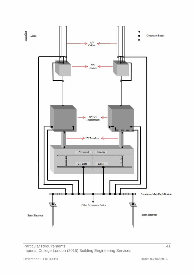
Particular Requirements 41 Imperial College London (2015) Building Engineering Services
Reference: EP01BESPR Date: 03/06/2016
Particular Requirements 42 Imperial College London (2015) Building Engineering Services
Reference: EP01BESPR Date: 03/06/2016
4
Design Criteria for Main Electrical Power Equipment 4.1 Main Electrical Equipment 4.1.1 Introduction The purpose of this section is to provide design criteria for Consultants and Contractors responsible for the procurement of switchgear installed within Imperial College. The strategy is to ensure that:
a) The Maintenance Teams and Contractors employed by the College can maintain and/or install additional circuits in switchgear without necessitating the isolation of adjacent live circuits.
b) Connections can be made to data system outputs without necessitating the
disruption or isolation of the primary power circuit. Proper consideration is given to switchroom size and layout to fulfil objectives a) and b). 4.1.2 HV Switchgear
4.1.2.1 Overview Multi-panel switchboards or ring main units (RMUs) control the College’s 6.6kV and 11kV networks. Both networks are connected as ring circuits but operate as radial feeds. Each ring has a third feeder coupled, where possible, at a node representing one half of the total ring current. The distribution feeders are protected against over-current and earth faults at the main switchboards and do not rely on intermediate downstream protection.

Particular Requirements 43 Imperial College London (2015) Building Engineering Services
Reference: EP01BESPR Date: 03/06/2016
Therefore, incoming circuits on intermediate switchgear panels are not equipped with protection relays and are used for manual sectionalising only. This replicates the function of the ring switches on RMUs. Multi-panel switchboards are used in substations where a third feeder interconnection is made and/or other switched HV functions are required e.g. PFC Capacitors and remotely switched transformer feeders. RMUs are used in substations utilizing plain transformer feeders and offer cost and possible space savings over multi-panel switchboards. Further savings are made if the RMUs can be close coupled to the transformers and some substations within Imperial College are equipped with up to 3 x 1600kVA transformers connected in this way.
4.1.2.2 HV Multi-panel Switchboards These shall be procured from Imperial College Framework Agreement Manufacturers and incorporate the following: • 12kV minimum rms working voltage • 630A minimum circuit breaker and bus-bar rating • 25kA – 3s symmetrical fault rating • Micom P122 or Sepam1000 protection device on transformer feeders only.
Device equipped with auxiliary relays to receive LV intertrip and lockout signals. • Vacuum breaking medium • Bus-section circuit breaker • All circuit breakers to be independent manual closing control and • fitted with 30V DC trip coil for local manual and protection trips • All circuit breakers to have lockable electrical trip control switches • One set of auxiliary contacts shall be wired out on the transformer panels to
provide an inter-trip signal to the transformer LV circuit breaker, which also acts as an interlock to prevent closure of the LV circuit breaker until the HV circuit breaker is closed.
4.1.2.3 HV Ring Main Units (RMUs) These shall be procured from Imperial College Framework Agreement Manufacturers and incorporate the following: • Through symmetrical fault rating 25kA 3s • Independent manual ring switch operation with minimum 630A rating for load
switching and through fault making capacity. • 200A rated vacuum or SF6 circuit breaker for controlling outgoing transformer
feeder. • Circuit breaker symmetrical breaking capacity of 21kA 1s • Non-TLF protection e.g. Schneider VIP 300 unit or discrete relay as in 2.1

Particular Requirements 44 Imperial College London (2015) Building Engineering Services
Reference: EP01BESPR Date: 03/06/2016
• 30V DC shunt trip coil • One set of auxiliary contacts shall be wired out on the transformer panels to
provide an inter-trip signal to the transformer LV circuit breaker, which also acts as an interlock to prevent closure of the LV circuit breaker until the HV circuit breaker is closed
• Suitable for close coupling to the transformer. Close coupled RMUs to have ground braced framework and not rely on the transformer LV flange for sole support.
4.1.3 Transformers These shall be procured from Imperial College Framework Agreement Manufacturers and be as follows: • KNAN Midel liquid cooled type • Nominally 11/0.398kV but if operated from the Imperial College • 6.6kV network 6.6/0.398kV, both at full load output. • Vector Group Dyn11 • Suitable for mounting close coupled RMU • The following shall be fitted: • Liquid Temperature Gauge with maximum temperature indicator and alarm and
trip contacts • Pressure relief device with trip contacts • Marshalling cubicle for accessory small wiring • Off-circuit HV tappings at ± 2.5% and ± 5% with lockable switch • Transformers in excess of 1600kVA, LV bus-bar flanges for coupling bus-bar
ducting • In exceptional circumstances it may be desirable to install cast resin transformers with the following fittings: • Nominally 11/0.398kV but if operated from the Imperial College • 6.6kV network 6.6/0.398kV both at full load output. • Vector Group Dyn11 • Thermocouple winding temperature system with 2 thermocouples/winding and
monitoring module providing temperature indication, alarm and trip signals • IP23 enclosure. The IP index may be reduced if ONAN cooling cannot be
achieved but clearances to live conductors must be such to comply with the IP standard “finger” test. Forced cooling of the enclosures shall be avoided
• Access to core and windings shall be limited by either a) interlocked doors with keys released by both HV and LV circuit breakers or b) removable panels with fastenings operated with special tools
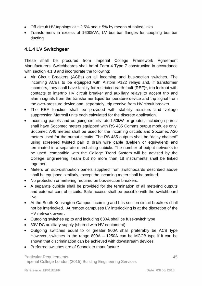
Particular Requirements 45 Imperial College London (2015) Building Engineering Services
Reference: EP01BESPR Date: 03/06/2016
• Off-circuit HV tappings at ± 2.5% and ± 5% by means of bolted links • Transformers in excess of 1600kVA, LV bus-bar flanges for coupling bus-bar
ducting 4.1.4 LV Switchgear These shall be procured from Imperial College Framework Agreement Manufacturers. Switchboards shall be of Form 4 Type 7 construction in accordance with section 4.1.8 and incorporate the following: • Air Circuit Breakers (ACBs) on all incoming and bus-section switches. The
incoming ACBs to be equipped with Alstom P122 relays and, if transformer incomers, they shall have facility for restricted earth fault (REF)*, trip lockout with contacts to intertrip HV circuit breaker and auxiliary relays to accept trip and alarm signals from the transformer liquid temperature device and trip signal from the over-pressure device and, separately, trip receive from HV circuit breaker.
• The REF function shall be provided with stability resistors and voltage suppression Metrosil units each calculated for the discrete application.
• Incoming panels and outgoing circuits rated 50kW or greater, including spares, shall have Socomec meters equipped with RS 485 Comms output modules only. Socomec A40 meters shall be used for the incoming circuits and Socomec A20 meters used for the output circuits. The RS 485 outputs shall be “daisy chained” using screened twisted pair & drain wire cable (Belden or equivalent) and terminated in a separate marshalling cubicle. The number of output networks to be used, compatible with the College Trend System will be advised by the College Engineering Team but no more than 18 instruments shall be linked together.
• Meters on sub-distribution panels supplied from switchboards described above shall be equipped similarly, except the incoming meter shall be omitted.
• No protection or metering required on bus-section breakers. • A separate cubicle shall be provided for the termination of all metering outputs
and external control circuits. Safe access shall be possible with the switchboard live.
• At the South Kensington Campus incoming and bus-section circuit breakers shall not be interlocked. At remote campuses LV interlocking is at the discretion of the HV network owner.
• Outgoing switches up to and including 630A shall be fuse-switch type • 30V DC auxiliary supply (shared with HV equipment) • Outgoing switches equal to or greater 800A shall preferably be ACB type
However, switches in the range 800A – 1250A can be MCCB type if it can be shown that discrimination can be achieved with downstream devices
• Preferred switches are of Schneider manufacture

Particular Requirements 46 Imperial College London (2015) Building Engineering Services
Reference: EP01BESPR Date: 03/06/2016
• Harmonic analysis needs to be done to determine the size of the PFC unit • If the Panel has two sections, each section should have a PFC unit sized
accordingly. • The College is to attend and sign off FAT testing for all LV switch panels.
4.1.5 Cable Systems HV Cable • XLPE, Cu, SWA with LS0H over sheath, sized 240mm² for all main feeders and
95mm² for all transformer feeders, except when close RMU coupled. • Cleated to ladder rack and not tie wrapped.
LV Cable & Conductor Systems • XLPE, Cu, SWA with LS0H over sheath, multicore • XLPE, Cu, AWA with LS0H over sheath, 1c for transformer incomers equal to or
less than1600kVA • Transformer incomers > 1600kVA to be connected by bus-bar trunking • Cables to be cleated to ladder rack or tray. Tie-wraps may use on earth
conductors or cables, 50 mm² or smaller only 4.1.6 Auxiliary Equipment Battery & Charger • 30V DC with charger failure alarm for remote signaling. (BMS) Substation Cooling • Preferably is air natural. If forced air is required is naturally vented input and
forced output. • Temperature alarm required for remote signaling. (BMS)
4.1.7 Earthing This section shall be read in conjunction with section 3, Earthing. Wall mounted main earth bar to be provided. If immediate ground access is available two earth electrodes are to be provided with target earth resistance of 10 ohms each. The following bonding shall be made at all South Kensington substations: • Panel HV switchgear, one bond at each end • RMU, one bond. This may be to transformer if close coupled • Transformers 2. One on each lug or boss • LV Switchgear, one bond at each bus-bar section

Particular Requirements 47 Imperial College London (2015) Building Engineering Services
Reference: EP01BESPR Date: 03/06/2016
• LV Neutral Earth within switchboard to main earth bar via removable links. One link for each transformer incomer.
• Incoming HV cable armoured. One bond per cable • All outgoing cable earth conductors bonded to main switchboard earth bar For other Imperial College campuses the requirements of the local electricity operator shall be adhered to. Where LV earths are the responsibility of Imperial College, then earth electrodes less than or equal to1 ohm shall be provided and permission to bond to the HV earth sought from the electricity operator. 4.1.8 Switchgear Form of Separation LV switchboards will be manufactured in accordance with BS EN 61439-2. The form of separation shall be defined in accordance with the BEAMA guide, which forms the National Annex to BS EN 61439-2. The standard for the College has been set at Form 4 type 7 of the BEAMA guide. It is appreciated that this form of construction is the most rigorous and the following factors should be taken into account when specifying switchboards to this standard:
4.1.8.1 Termination of the cables may be made in suitable chambers (cable boxes) externally mounted to the main panel construction.
4.1.8.2 The cable boxes shall take account of the cable lay-up and containment configuration and shall be suitable for top, bottom or dual entry as necessary.
4.1.8.3 Care shall be exercised to ensure that the cables of adjacent circuits have free alignment with their respective cable box to enable proper termination of cable glands. This may require staggering the cable entry points along the main (lengthwise) axis of the switchboard.
4.1.8.4 It shall be possible to make off and access the cable core terminations without the dismantlement of any of the outgoing circuit breaker, fuse or control gear and adjacent circuits, whilst retaining the separation requirement.

Particular Requirements 48 Imperial College London (2015) Building Engineering Services
Reference: EP01BESPR Date: 03/06/2016
4.1.8.5 Where circuits require more than one cable, connected in parallel to overcome derating or voltage drop considerations, the cable termination boxes shall be adequately sized and comply with paragraphs 4.1.2.1 to 4.1.2.4 inclusive. 4.1.9 Data and Metering Cables Imperial College has a basic requirement to provide remote energy metering using pulsed outputs from switchboard instrumentation, which is then configured in local outstations for input to the College BMS “Trend” system. The College seeks to extend the parameters monitored to exploit the data available from the instrumentation and provide accurate trends for the network. To facilitate this, the following features shall be incorporated into new switchboards:
4.1.9.1 Signals derived from instruments for remote monitoring shall be wired out to a separate compartment free of low voltage rated components. Data terminal blocks located within switchgear cubicles fitted with door interlocks preventing access before the power circuit is isolated will not be accepted.
4.1.9.2 The Compartment(s) shall be suitable for direct termination of data cables and the internal wiring shall be compliant with the standard of the transmitted data e.g. RS 485. 4.1.10 Switchroom Design It is important that the impact of complying with this strategy is fully recognised when designing the switchroom layout. Inadequate space allowance will not be accepted for nonconformance with this strategy. 4.1.11 Compliance Any non-conformance with this Particular Requirement will not be accepted unless the Imperial College Estates Engineering Team has approved it in writing. Any request for waivers shall be accompanied by supporting documentation and drawings. If difficulty is anticipated in complying with this strategy then it shall immediately be brought to the attention of the Imperial College Engineering Manager.
Particular Requirements 49 Imperial College London (2015) Building Engineering Services
Reference: EP01BESPR Date: 03/06/2016
4.2 Separation Form for LV Panels 4.2.1 Purpose The purpose of this document is to provide design criteria for Consultants and Contractors responsible for the procurement of LV switchgear installed within the Imperial College. The strategy is to ensure that: 1. The College’s Maintenance Teams and Contractors employed by the College can
maintain and/or install additional circuits in switchgear without necessitating the isolation of adjacent live circuits.
2. Connections can be made to data system outputs without necessitating the
disruption or isolation of the primary power circuit. Proper consideration is given to switchroom size and layout to fulfil objectives a) and b). 4.2.2 Switchgear Form of Separation LV switchboards will be manufactured in accordance with BS EN 61439-2. The form of separation shall be defined in accordance with the BEAMA guide, which forms the National Annex to BS EN 61439-2. The standard for the College has been set at Form 4 type 7 of the BEAMA guide. It is appreciated that this form of construction is the most rigorous and the following factors should be taken into account when specifying switchboards to this standard:
4.2.2.1 Termination of the cables may be made in suitable chambers (cable boxes) externally mounted to the main panel construction.
4.2.2.2 The cable boxes shall take account of the cable lay-up and containment configuration and shall be suitable for top, bottom or dual entry as necessary.
4.2.2.3 Care shall be exercised to ensure that the cables of adjacent circuits have free alignment with their respective cable box to enable proper termination of cable
Particular Requirements 50 Imperial College London (2015) Building Engineering Services
Reference: EP01BESPR Date: 03/06/2016
glands. This may require staggering the cable entry points along the main (lengthwise) axis of the switchboard.
4.2.2.4 It shall be possible to make off and access the cable core terminations without the dismantlement of any of the outgoing circuit breaker, fuse or control gear and adjacent circuits, whilst retaining the separation requirement.
4.2.2.5 Where circuits require more than one cable, connected in parallel to overcome derating or voltage drop considerations, the cable termination boxes shall be adequately sized and comply with paragraphs 4.2.2.1 to 4.2.2.4 inclusive. 4.2.3 Data and Metering Cables Imperial College has a basic requirement to provide remote energy metering using pulsed outputs from switchboard instrumentation, which is then configured in local outstations for input to the College BMS “Trend” system. The College seeks to extend the parameters monitored to exploit the data available from the instrumentation and provide accurate trends for the network. To facilitate this, the following features shall be incorporated into new switchboards:
4.2.3.1 Signals derived from instruments for remote monitoring shall be wired out to a separate compartment free of low voltage rated components. Data terminal blocks located within switchgear cubicles fitted with door interlocks preventing access before the power circuit is isolated will not be accepted.
4.2.3.2 The Compartment(s) shall be suitable for direct termination of data cables and the internal wiring shall be compliant with the standard of the transmitted data e.g. RS 485. 4.2.4 Switchroom Design It is important that the impact of complying with this strategy is fully recognised when designing the switchroom layout. Inadequate space allowance will not be accepted for non-conformance with this strategy.
Particular Requirements 51 Imperial College London (2015) Building Engineering Services
Reference: EP01BESPR Date: 03/06/2016
4.2.5 Compliance Any non-conformance with this document will not be accepted unless the Imperial College Estates Engineering Team has approved it in writing. Any request for waivers shall be accompanied by supporting documentation and drawings. If difficulty is anticipated in complying with this strategy then it shall immediately be brought to the attention of the Imperial College Engineering Manager.
4.3 LV Electrical Panels rated up to 800A 4.3.1 Purpose and Scope This Particular Requirement provides the technical requirements for the College’s LV electrical switch and panel boards for bus-bar ratings of 800A and below, This does not including Motor Control Centre Panel's (MCCPs) and final distribution boards for power and lighting. For main intake switchgear and switchboards with ratings 800A and above the 4.2 will apply, where the minimum separation requirement is Form 4, Type 7. However, it is appreciated that, for downstream applications where shutdowns are permissible, this requirement can be eased. Some discretion is permitted for determining the actual separation value dependent upon the user function. For example, if the board is supplying a suite of research facilities then the separation should be more stringent than a suite of offices enabling routine maintenance to be carried out at a convenient time. All proposals shall be submitted to the Engineering Manager for approval at an early stage of the design. 4.3.2 Form of Separation For general switch panels up to 630A the form of separation shall not be less than Form 2 Type 1 (2b) and for switch panels up to 800A or in research environments not less than Form 4 Type 1 (4a). 4.3.3 Configurations Normally the switchboards/panels will be fed from a single source switch mounted in a main switchboard in accordance with section 4.1. Up to 630A rating the controlling device will be a fuse switch and up to 800A an MCCB. Therefore, the incoming switch on the switchboard/panel shall not have a protection device, but should be provided with four pole isolation and should be capable of making and breaking normal full load current. It is the responsibility of the designer to ensure that the
Particular Requirements 52 Imperial College London (2015) Building Engineering Services
Reference: EP01BESPR Date: 03/06/2016
rating of the fuse or set point of the MCCB on the upstream device is selected in accordance with the switchboard/panel rating. No outgoing switch shall be selected that cannot discriminate with the main incoming protection device, nor shall the switchboard/panel fault rating be lower than the fault rating delivered by the controlling switch. Where it is necessary to provide two, separate source, incoming supplies a bus-section switch shall be provided having the same rating as the incoming switches. Normally the incoming and bus-section switches will be provided with a key interlock to enable two out of three switches to be closed. Occasionally it will be necessary to omit the interlocks to meet the requirements of the user where it is desirable to transfer the load source without interruption. It then becomes the responsibility of the Imperial HV Operator to control the operation of these switches and they shall be labelled accordingly. Currently our HV networks are operated by external service providers/consultants, who will provide the labels. Where it is considered necessary to omit bus-section interlocks, prior authorisation will be required via an Exception Report submitted for joint approval by the Engineering Manager and Head of Maintenance. 4.3.4 Outgoing devices Outgoing devices may be either fuse switches or MCCBs with a fault rating of not less than 40kA 4.3.5 Metering Metering shall be in accordance with the Metering Particular Requirement.

Particular Requirements 53 Imperial College London (2015) Building Engineering Services
Reference: EP01BESPR Date: 03/06/2016
Particular Requirements 54 Imperial College London (2015) Building Engineering Services
Reference: EP01BESPR Date: 03/06/2016
5
Electrical Load Calculations 5.1 General The appropriate load calculations shall be included for all designs presented to the college for comment and/or information. Designers are required to enter the appropriate values into the attached template(s), duplicating templates as necessary, according to the size and complexity of the distribution system. Related Document : IC Load Balance Sheet.xls – Excel file.
Particular Requirements 55 Imperial College London (2015) Building Engineering Services
Reference: EP01BESPR Date: 03/06/2016
6
Connection of Large Electrical Loads 6.1 Introduction The purpose of this section is to provide guidance criteria for the connection of large electrical loads where:
a) There is possibility of exceeding statutory voltage limits at the point of utilisation and,
b) The security of supply is jeopardised by exceeding the system design resilience
This applies at the Imperial College South Kensington campus, where the HV and LV networks are owned and maintained by the College and, for outlying sites, where the College is responsible for operating and maintaining its own HV network. 6.2 Voltage Limits The LV network at the South Kensington campus is presently regulated to 415/240V, three phase, and 50Hz at the distribution transformer LV terminals. This shall be deemed the supply point nominal voltage in accordance with The Electricity Safety, Quality and Continuity Regulations 2002. The connection of any additional load shall not produce a voltage drop in excess of 4% of the nominal voltage at the fixed point of utilisation in accordance with BS 7671, Requirements for Electrical Installations. At new locations the nominal supply voltage shall be regulated to 398/230V, three phase, 50Hz at the distribution transformer LV terminals. Any load, potentially exceeding these voltage drop limits, shall be immediately brought to the attention of the Imperial College Engineering Manager.
Particular Requirements 56 Imperial College London (2015) Building Engineering Services
Reference: EP01BESPR Date: 03/06/2016
6.3 Supply Security
The criteria applied to the South Kensington campus is as follows:
For teaching, research and administration complexes redundant capacity is provided to enable one transformer to be taken out of service without loss of supply to any of the connected loads. Normally, this is achieved by dual redundancy i.e. two units, each rated to supply the total prospective load. Alternatively, where essential loads are supported by UPS systems, backed up with standby generation, this may be relaxed to three units, each rated to supply 66% of the total prospective load. The second alternative is to be considered where transformer and switchgear ratings exceed practical values or, where unacceptable fault levels arise. For other areas, principally hostel accommodation; the dual redundancy rule is relaxed. However, if dual redundancy is not applied, a second standby supply from a separate source (usually an adjacent substation) may be required. This criterion is presently applied to the Princes Gardens complex, which comprises a mixture of accommodation and other College facilities. Any load potentially jeopardising these security criteria shall be immediately brought to the attention of the Imperial College Engineering Manager. 6.4 Requirement for New Substations Where it is necessary to provide a new substation to meet the criteria of items 6.2 and 6.3 above it shall be located as near as possible to the main load centres. The substation shall be designed to accommodate all HV switchgear, transformers and LV switchgear within a common area and to include, if possible, any necessary Motor Control Centres (MCC). If the motor loads are not located near the substation then the MCC(s) shall be positioned to optimise the motor distribution cabling in order that voltage drops do not exceed 15% at the motor terminals during starting. If it is necessary to provide standby generation then the installation shall be located as close to the substation as possible, including the fuel bunkering. When a new substation is required it shall be first agreed with the Imperial College Engineering Manager.

Particular Requirements 57 Imperial College London (2015) Building Engineering Services
Reference: EP01BESPR Date: 03/06/2016
7 Controls 7.1 Introduction This document has been prepared to ensure that all future developments to the Imperial College Building Energy Management System are of the required College standard, consistent with existing installations and that all information is represented in an approved format. The standards set out in this document will act as guidance to Imperial College engineers, external consultants and approved suppliers on the principal of design, engineering and installation issues. To achieve the above requires designers, installers and those responsible for commissioning and validation, to comply with the standards set out in this document. The requirements contained within this document are supplementary to those contained in any other contract documentation or standard policy document. Any proposed deviations from this document must be agreed with the Imperial College London, Engineering Manager. 7.2 General 7.2.1 Introduction Trend Control Systems have been identified by Imperial College as the standard for the Building Energy Management System (BEMS) in all buildings serviced by Estates.

Particular Requirements 58 Imperial College London (2015) Building Engineering Services
Reference: EP01BESPR Date: 03/06/2016
7.2.2 The appointed controls specialist shall be responsible for the disconnection of all relevant controllers from the College network prior to commencement of works. 7.2.3 The Imperial College BEMS shall be designed around the Trend product range and fully integrated into the College Trend network. The College BEMS 7.2.4 Trend IQ4 series controllers are to be utilised. Programmable IQEco terminal unit controllers may be used where appropriate. 7.2.5 Where there is a requirement for ICT data sockets to be installed this work is to be undertaken by the College’s approved ICT Data installer. 7.2.6 It is the responsibility of the controls specialist to advise the PM (in good time) of the quantity and location of the data sockets for each project. Unique outstation address’s, LAN numbers and device Hostnames must be applied for (in good time) by the controls specialist via the PM. Please note that the MAC addresses of each associated device will be required at this time. 7.2.7 Packaged plant controls will also utilise Trend controllers for their final control. Where Trend controllers cannot be fitted as standard a full read / write interface shall be provided. Should there be a need to deviate from this a full discussion should take place with the College’s BEMS engineer before a detailed exception report be presented to the College Engineering Manager. 7.2.8 Schematic graphic pages shall be provided for each item of plant. These pages will follow the format detailed later in this document and will operate from the existing
Particular Requirements 59 Imperial College London (2015) Building Engineering Services
Reference: EP01BESPR Date: 03/06/2016
963 client server. No other stand-alone supervisors will be allowed to be connected to the network. 7.2.9 When engineering the system consideration should be given to keep communications traffic to a minimum. In general all common items of plant shall be controlled from a single outstation and not from two smaller ones. The use of multiplexed input and output modules will not be permitted. 7.2.10 25% spare input and 25% spare output capacity shall be allowed to accommodate additions to the system. 7.2.11 An approved Trend system integrator (Controls Specialist) shall be used to design, install and commission the control system and control panels. A list of currently approved Controls Specialists is available from the approved suppliers list. 7.2.12 Information regarding the BEMS should be requested (via the Project Manager in the case of a project), from the College by the completion of form EN3/RFI/01. 7.2.13 Final commissioning of the control system shall only commence when all associated air and water systems are fully balanced. Details of the requirements for commissioning the control system are detailed later in this document. 7.3 Control Panels 7.3.1 Control panels shall be supplied and manufactured by the controls specialist selected for the project.

Particular Requirements 60 Imperial College London (2015) Building Engineering Services
Reference: EP01BESPR Date: 03/06/2016
7.3.2 Control panels shall be divided into two sections, one for power and one for controls. The controls section shall be lockable using approved keys (C21323) or (1242E). The power section shall be door isolator interlocked. The power section shall not contain any items of equipment likely to be accessed during normal plant operation and maintenance. 7.3.3 Each section of the control panel will incorporate a light arranged to extinguish on door closure. 7.3.4 The controls section shall incorporate a 13A. RCD protected socket outlet supplied from the live side of the isolator to supply power for a laptop computer. 7.3.5 All control circuits shall be low voltage 24Vac. and supplied from a transformer with a minimum rating of 200 VA. 7.3.6 Field wiring shall be wired individually from the control panel, the use of multi-core cables with joint boxes will not normally be permitted, however where packaged plant is utilised an exception can be raised. Controls related equipment shall be wired via isolation terminals. 7.3.7 An MCB identification chart shall be supplied and permanently fixed in the section of the control panel housing the MCB’s. 7.3.8 A copy of the “as fitted” panel wiring diagram shall be located within the controls section of the control panel in a mounted document wallet.
Particular Requirements 61 Imperial College London (2015) Building Engineering Services
Reference: EP01BESPR Date: 03/06/2016
7.3.9 Motor starters shall be of the non-enclosed type with coils rated at 24Vac. 7.3.10 Fascia switches and indicators shall be identified with engraved traffolyte labels. Switches to override automatic operation shall have the inscription ‘Hand/Off/Auto. The control panel shall have its designated asset number engraved on a traffolyte label. 7.3.11 MCB’s shall provide protection for all fans, pumps and control circuits. Fuses shall not normally be used. 7.3.12 Panel fascia indication shall be by means of multi cluster LED’s with a minimum intensity of 240cd/m². Colour configuration shall be as follows: - Green - Run indication (positive feedback) Amber - Enabled indication (no positive feedback) Red - Fault indication Blue - Frost indication White - Control circuit live indication A lamp test facility shall also be provided. 7.3.13 Cable termination ferrules shall be utilised and markers shall be used to identify all control panel and field terminations in line with the control specialists wiring diagram. 7.3.14 Were a combination of different coil voltages for plug in relays within a control panel exist, bases with a different pin configuration shall be used for each voltage present. 7.3.15

Particular Requirements 62 Imperial College London (2015) Building Engineering Services
Reference: EP01BESPR Date: 03/06/2016
All exposed live electrical terminations and equipment within both power and control sections shall be shrouded against accidental contact. 7.3.16 The status of all plant switches on the control panel facia shall be monitored by a single digital input. This input will be used to indicate on the plant schematics when any piece of plant is NOT in auto. 7.3.17 A master plant reset button shall be incorporated on the control panel facia. The function of this push button is to reset all plant that requires a software reset. The operation of this button shall have no effect on plant that does not require a reset. The reset button may be omitted providing there is no plant within the control panel that requires a reset. 7.3.18 Where there is a requirement for the Trend equipment to be connected to the College IT system, connections shall be within the control panel. 7.4 Outstations 7.4.1 All outstations shall be of the 230Vac version. Outstations will be supplied complete with all necessary input/output cards or modules required to provide a fully operational controls package. FCU outstations can be 24Vac if fed from the FCU manufacturer’s equipment. 7.4.2 Outstations located remotely (i.e. FCU’s) shall be isolated adjacent to the outstation and not in a position were accidental isolation can occur.

Particular Requirements 63 Imperial College London (2015) Building Engineering Services
Reference: EP01BESPR Date: 03/06/2016
7.4.3 Outstations mounted within a control panel shall have all of its input/output terminals wired to terminal rail located at the top or bottom of the panel. This is to include the 25% spare capacity and network connections. 7.4.4 Where current Trend current loop is used, the network speed for outstations shall be set for 19k2. 7.4.5 All cables shall be numbered at each end using the same numbering topology used for the associated control panel terminal numbers. 7.4.6 Cable screens shall be grounded at the controller only. The cable should be made off with ‘Helleman’ type expanding sleeves with the screen sleeved in green / yellow. 7.4.7 Field equipment that requires specialised wiring or device set up should be clearly documented. Devices requiring to be set up using switches, jumpers or other method should in addition to the documentation have these details contained within the device. 7.4.8 Where outstations are supplied and fitted within other manufacturer’s equipment it will be the responsibility of the appointed controls specialist to: -
a) Ensure the strategy complies with this document. b) Commission the communications. c) Connect to the College network. d) Provide the graphic pages required by this document.
7.4.9 Where there is a requirement for an interface between manufacturer’s equipment and the Trend control system, it shall be the manufacturer’s responsibility to supply
Particular Requirements 64 Imperial College London (2015) Building Engineering Services
Reference: EP01BESPR Date: 03/06/2016
the required interface device. They should liaise with the Controls Specialist to determine the College requirements. 7.5 IQ Engineering 7.5.1 Details of the controls philosophies together with standard strategies are continually being developed and a copy of the latest strategies should be requested from the Imperial College London, Engineering Team, Controls Engineer. The standard strategies should be used to build up an outstation configuration or be used in full in the case of fan coil units. 7.5.2 Strategy design should be carried out in a consistent, structured manner and be kept as simple as possible. 7.5.3 Each point in a controller shall be labelled in a unique and unambiguous manner. Any reference to room numbers should ensure the final College room number is used and not project numbers. Room numbering is obtained from the Imperial College London, Space Management Team. 7.5.4 The identifier of a controller or INC should indicate the area and / or plant that is being controlled 7.5.5 The identifier in fan coil unit controllers should indicate the final College room number to allow for the use of generic graphic pages. Room numbering is obtained from the Imperial College Estates Space management Team. 7.5.6 It is the Controls Specialists responsibility to ensure that no conflicts occur with the existing College network when using IC communications.
Particular Requirements 65 Imperial College London (2015) Building Engineering Services
Reference: EP01BESPR Date: 03/06/2016
7.6 Supervisor Engineering 7.6.1 The College supervisors consist of two 963 client / servers operating as duty standby with a further 963 engineering machine. Access to the servers will not be available to the controls specialist. New projects will be added to the engineering machine only, to allow the new pages to be fully tested and witnessed by the Imperial College Controls Engineer. Once this process is completed the Project Manager will notify the relevant parties in FM that the project is ready to transfer from the Engineering PC to the Trend 963 servers. A defect is raised and the work completed within 5 working days. 7.6.2 Access to Trend schematic pages shall be with a client PC via the Trend 963 Server, no other stand-alone supervisors will be connected to the College network. 7.6.3 The Controls Specialist shall obtain the latest file structure, analogue library, image library, animation library and backdrops library before commencing schematic page construction. To ensure correct operation of the schematic pages on the server these details must be strictly adhered to all graphic background are to be jpeg files. No additional files will be added to the libraries without authorisation. 7.6.4 Schematic pages shall be provided for each item of plant supplied on the project. Plant that is monitored only by the control system will also have a schematic page with a note on the page indicating that the plant is not controlled by Trend. 7.6.5 A standard schematic page format for an item of plant shall consist of two pages. The first page shall be a view only page indicating the true operation of the plant. BEMS enable points shall not generally be used, the read-back point shall be
Particular Requirements 66 Imperial College London (2015) Building Engineering Services
Reference: EP01BESPR Date: 03/06/2016
utilised, indicating that the plant is operating. The second page shall consist of an adjustments page showing all available plant settings and secured as detailed below. 7.6.6 Time zones should be accessed via a button on the adjustments page set at a PIN level of 90. 7.6.7 Buttons on the adjustments page should be provided to: - • Override control valve and damper actuators. • To enable the valve exercise routine. • To operate a 1 hour plant extension routine • These buttons are to be set with a PIN level of 10.7.6.8 Knobs are to be provided on the adjustments page to: - Position valve and damper actuators when in override. Allow adjustment of set points. These buttons are to be set with a PIN level of 10 for standard set points and overrides, 50 for engineering set points and 90 for critical set points that would have a detrimental effect on the system operation. 7.6.8 Floor plans shall be provided detailing locations of plant and actual College room numbers. They should be provided in bmp format and be inserted onto an ‘Imperial College blank’ backdrop. 7.7 Additions to the Existing System 7.7.1 New works shall comply fully with this document. Requests for Host Names, LAN and outstation numbers shall be obtained by the completion of form EN3/RFI/01. 7.7.2 Where retrofit works are carried out to existing items of plant and control panels the following shall be closely adhered to.

Particular Requirements 67 Imperial College London (2015) Building Engineering Services
Reference: EP01BESPR Date: 03/06/2016
7.7.3 Existing documentation will be ‘back engineered’ and provided in SET format. 7.7.4 Outstation firmware shall be updated to the current version. 7.7.5 Redundant field and control panel equipment shall be removed. Any holes left in control panel doors shall be covered with permanent Traffolyte labels. 7.7.6 Where existing equipment is to be re-used it is the controls specialists’ responsibility to ensure it is in good working order. The Project Manager should be advised if a replacement is required. 7.7.7 Wherever practically possible the requirements of this document shall be complied with in full. Any proposed deviations from this document must be agreed with the Imperial College Controls Engineer or the Engineering Manager. 7.7.8 Additions to the existing system shall be engineered to fully integrate with existing plant. This shall include but is not limited to: -
• Boiler interlocking for heat demands. • Chiller interlocking for cooling demands. • Frost protection requirements. • Interlocking of time zones and calendar scheduling.
7.7.9 Extensions to the College network both inter-network and local area network shall be carried out using Trend approved cabling. The cable will be marked every 20 meters or change of direction with an engraved Traffolyte label fixed to the cable using cable ties: -

Particular Requirements 68 Imperial College London (2015) Building Engineering Services
Reference: EP01BESPR Date: 03/06/2016
The above requirement can be omitted providing the cable is marked throughout its entire length with ‘Trend’. 7.7.10 SWA Network cable will be used outside of plant room areas for distances exceeding 10m. (Excluding FCUs). Network cable specification: To manufacturer’s recommendations. 7.7.11 Extensions to the inter-network or local area network will be carried out from an existing controller. Junction boxes will not be allowed. Network extensions at South Kensington shall not emanate from ‘HUB’ panels 7.7.12 Prior to the final connection to the College network two copies of the cable route details are to be provided to the Imperial College Controls Engineer. 7.8 Field Wiring & Equipment 7.8.1 Control valves shall be of Trend/Honeywell manufacturer and shall be installed to meet the requirements of their data sheets. Control valves fitted to steam and MPHW shall be manufactured from:-
a) Nodular Iron on systems up to 2 bar or 50mm diameter. b) Cast Steel shall be used on all other installations. c) Actuators should be the spring return type.
7.8.2 All main plant field devices are to be identified with identification tags, with the tag being attached as close as possible to the device. The tags shall comprise Dyna Tape labels fixed to marker plates selected from the IMP range as manufactured by Hellermann Tyton (or equal and approved) Hand written labels will not be accepted.

Particular Requirements 69 Imperial College London (2015) Building Engineering Services
Reference: EP01BESPR Date: 03/06/2016
7.8.3 All modulating control valve and damper actuators shall have a power supply voltage of 24V ac. and a control voltage of 0-10 V dc, with the exception of fan coil units. 7.8.4 All sensors, variable speed drives and valve actuators are to be manufactured by Trend/Honeywell Control Systems unless prior approval is obtained from the Imperial College Engineering Team. The only exceptions to this are Steam and MPHW valves which are to be Honeywell or Siemens manufacture and variable speed drives which can be of Danfoss manufacture.
Packaged plant controls will utilise Trend controllers for their final control. Where Trend controllers cannot be fitted as standard a full read / write interface shall be provided. Should there be a need to deviate from this a full discussion should take place with the Imperial College Engineering Team and an Exceptions Report submitted. 7.8.5 Monitoring of filters shall utilise differential pressure sensors with dirty filter indication on the schematic pages originating from the alarm bit. 7.8.6 All cables shall be numbered at each end using the same numbering topology used for the associated control panel terminal numbers. 7.8.7 All field equipment shall be wired using manufacturers recommended cable. 7.8.8 Due consideration to be given to the selection and location of all field devices to ensure that adequate protection is provided against water and dust ingress, UV degradation and the effects of temperature. 7.9 Alarm Reporting 7.9.1 Alarm reporting will be filtered using point labels and LAN addresses. Alarms shall be assigned to groups to allow flexibility.
Particular Requirements 70 Imperial College London (2015) Building Engineering Services
Reference: EP01BESPR Date: 03/06/2016
7.9.2 No alarms shall be set in the controls strategy until commissioning has been completed.
7.9.3 The Project Manager shall co-ordinate with the appointed Controls Specialist and the Head of Maintenance to create a list of the critical alarms required, their priority and destination addresses. 7.9.4 Alarms shall only be reported when the associated plant is intended to be operational. It is the Controls Specialist responsibility to ensure that alarm levels and time delays are set at realistic settings. The Controls Specialist shall inform the Project Manager should the requested settings not be achievable. The Project Manager should then co-ordinate the appropriate action to rectify any design issues. 7.10 Metering 7.10.1 Please refer to the Metering section of this document. 7.11 Lighting 7.11.1 Centralised systems may be controlled using the College’s BEMS Trend system. Lighting circuits shall be controlled via contactors/Lighting Control Modules (LCM’s), connected to a BEMS outstation. This may be available on a fan coil unit if it is installed in the same area as the lighting, otherwise a dedicated outstation may be required. 7.11.2 The BEMS Trend system is capable of but not limited to:
Providing volt free contacts 0v-10v for dimming On/off, scene settings (i.e. 10%, 50%, 100% etc) Controls through day light sensing, PIR, occupancy detection, etc.

Particular Requirements 71 Imperial College London (2015) Building Engineering Services
Reference: EP01BESPR Date: 03/06/2016
Time zone settings for different days of the week Provision of override switching
7.11.3 Where complex lighting control arrangements are required which are outside normal Trend capabilities, the Ligo system (as manufactured by Open Technology may be utilised in conjunction with a virtual IQ with prior consent. 7.11.4 When utilising a FCU output in a modular space, the heating and cooling dead band should be increased when the area is out of occupancy. 7.11.5 Further details of the College lighting policy can be found in the relevant section of this document. 7.12 Commissioning / Witnessing 7.12.1 Connection to the College network shall not take place until the system is fully documented, commissioned, validated, witnessed and accepted by the Imperial College Controls Engineer. Refer to the ‘Independent Validation Engineer Scope of Duties’ document. 7.12.2 Prior to witnessing the Project Manager shall ensure the following documentation is supplied to the College Controls Engineer: - a) LAN wiring drawing for the project from point of connection. b) Description of operation. c) Panel wiring diagrams. d) Strategy diagrams. e) Commissioning sheets showing an independent point check by a College appointed validation engineer. 7.12.3 The format for witnessing by the College Controls Engineer shall be: - a) Review of the documentation. b) Inspection of the field equipment. c) Scan and compare with the software supplied at the design stage.
Particular Requirements 72 Imperial College London (2015) Building Engineering Services
Reference: EP01BESPR Date: 03/06/2016
d) Witnessing of approximately 10% of the input / output points. e) Functionality test of the software. f) Operational stability of the system. g) Connection to the College network. h) Security applied to the outstations. 7.12.4 Following the completion of 7.12.3 the schematic pages can be installed onto the 963 engineering machine. Projects not witnessed within 10 days will be removed from the Engineering Machine and all relevant data sent to the Project Manager for filing. The format for witnessing of the schematic pages to the College Controls Engineer shall be: - a) Confirm file structure and pages to be copied to the engineering machine. b) Copy files to project folders. c) Witness 100% operation of pages and points ensuring compliance with strategies. 7.13 Documentation 7.13.1 The documentation required by this document is over and above the College operation and maintenance manual requirements and should be supplied direct to the College Controls Engineer. 7.13.2 Connection to the College network will not take place until the documentation required by section 7.12.2 is in place. 7.13.3 On completion of the commissioning and witnessing a soft copy of the documentation on a ‘CD’ shall be supplied. The following documentation shall be supplied to the College Controls Engineer within 5 days: - a) Description of services governed by each controller (PDF format). b) Control strategy drawings (PDF format). c) Control strategy files (SET format). d) Description of operation for each plant (PDF format). e) Schedule of equipment (PDF format). f) Control panel wiring diagrams (PDF format).

Particular Requirements 73 Imperial College London (2015) Building Engineering Services
Reference: EP01BESPR Date: 03/06/2016
Provide 3 No. Copies of the information required under this clause, all in CD format.
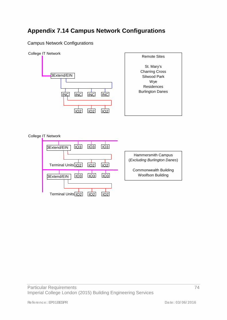
Particular Requirements 74 Imperial College London (2015) Building Engineering Services
Reference: EP01BESPR Date: 03/06/2016
Appendix 7.14 Campus Network Configurations Campus Network Configurations
College IT Network
3Extend/EIN
INC INC INC INC
IQ2 IQ2 IQ2
Remote Sites
St. Mary’s Charring Cross Silwood Park
Wye Residences
Burlington Danes
College IT Network
3Extend/EIN
IQ2 IQ2 IQ2
Hammersmith Campus (Excluding Burlington Danes)
Commonwealth Building
Woolfson Building L Bl k
IQ3 IQ3 IQ3
Terminal Units
3Extend/EIN
IQ2 IQ2 IQ2
IQ3 IQ3 IQ3
Terminal Units

Particular Requirements 75 Imperial College London (2015) Building Engineering Services
Reference: EP01BESPR Date: 03/06/2016
Appendix 7.15 Standard Imperial Campus College Codes This appendix details the standard Imperial College codes to be used for outstation identifiers and labels. Device information may also be written in full as an alternative to using codes. Further information regarding additional codes can be obtained from the (Job Title). Identifier construction should follow: - Site Code-Building Code-Level-BMS (LAN number)-Outstation number). The only exception to this shall be FCU’s which should follow: - FCU Reference-Building Code-Room number. Label construction should follow: - Equipment Code-Number-Device Type-Number-Device condition. The ‘Number’ is used only if applicable. Should abbreviations need to be used they should follow those detailed latter in this appendix. Table 7.1 Campus Site Codes Campus Site Code Campus Name SK South Kensington HM Hammersmith CX Charing Cross SP Silwood Park SM St. Mary’s W Wye
College IT Network
HUB 1
South Kensington Campus
HUB 2 HUB 3 HUB 4 HUB 5
HUB 6 HUB 7 HUB 8 HUB 9 HUB 10
3Extend/EIN
3Extend/EIN
3Extend/EIN
3Extend/EIN
IQ3 Exact 3Extend/EIN
Particular Requirements 76 Imperial College London (2015) Building Engineering Services
Reference: EP01BESPR Date: 03/06/2016
NH Royal Brompton - National Heart and Lung EG Evelyn Gardens PB Pembridge HL Harlington Sports Centre PT Putney Boat Station TD Teddington Sports Centre IW Imperial West Table 7.2 Imperial College Campus Building Codes
Campus Code Building Name
Charing Cross Campus CXCB COMPARATIVE BIOLOGY BLOCK
Charing Cross Campus CXCC CLAYBROOK CENTRE
Charing Cross Campus CXLB LAB BLOCK
Charing Cross Campus CXGH GLENISTER HALL
Charing Cross Campus CXGS GAS STORE
Charing Cross Campus CXLB LAB BLOCK
Charing Cross Campus CXMO MEDICAL ONCOLOGY
Charing Cross Campus CXLB LAB BLOCK
Charing Cross Campus CXPA PEMBRIDGE GARDENS ANNEXE
Charing Cross Campus CXPG 28-32 PEMBRIDGE GARDENS
Charing Cross Campus CXPH PARSONS HOUSE
Charing Cross Campus CXRB REYNOLDS BUILDING
Charing Cross Campus CXLB LAB BLOCK
Chelsea & Westminster CXCW CHELSEA AND WESTMINSTER
Griffin Studios GRBA BLOCK A
Griffin Studios GRBB BLOCK B
Griffin Studios GRBC BLOCK C
Hammersmith Campus HMAN ANAESTHETICS (NEPTUNE BUILDING)
Hammersmith Campus HMBB B BLOCK
Hammersmith Campus HMBT 136 U BLOCK
Hammersmith Campus HMCB COLLIER BUILDING
Hammersmith Campus HMCR CLINICAL RESEARCH BUILDING
Hammersmith Campus HMCW COMMONWEALTH BUILDING
Hammersmith Campus HMDH 139 U BLOCK
Hammersmith Campus HMFF FRANCIS FRASER LABORATORIES
Hammersmith Campus HMHH HAMMERSMITH HOUSE
Hammersmith Campus HMIR INSTITUTE OF REPRODUCTIVE AND DEVELOPMENTAL BIOLOGY
Hammersmith Campus HMJB J BLOCK
Hammersmith Campus HMLB L BLOCK
Hammersmith Campus HMLM LOWER MEDICAL CORRIDOR
Hammersmith Campus HMMR MRC CYCLOTRON BUILDING
Particular Requirements 77 Imperial College London (2015) Building Engineering Services
Reference: EP01BESPR Date: 03/06/2016
Hammersmith Campus HMMT MRC ANNEXE
Hammersmith Campus HMWF WOLFSON CONFERENCE CENTRE
Hammersmith Campus HMWS CAMPUS CHEMICAL WASTE STORE
Harlow Campus HWPC NATIONAL PHENOME CENTRE
Imperial West IWZZ WOODLANDS CAMPUS
Imperial West IWAB BLOCK A
Imperial West IWBB BLOCK B
Imperial West IWB1 BLOCK B1
Imperial West IWB2 BLOCK B2
Imperial West IWB3 BLOCK B3
Imperial West IWB4 BLOCK B4
Imperial West IWBC BLOCK C
Imperial West IWBD BLOCK D
Imperial West IWBE BLOCK E
Imperial West IWBF BLOCK F
Imperial West IWBG BLOCK G
Imperial West IWDC DATA CENTRE
Imperial West IWFH FOREST HOUSE
Imperial West IWJ1 BLOCK J1
Imperial West IWJ2 BLOCK J2
Imperial West IWJ3 BLOCK J3
Imperial Wharf WHOR ORIENT HOUSE
Royal Brompton Campus NHCW CHELSEA WING
Royal Brompton Campus NHGS GUY SCADDING
Royal Brompton Campus NHEK EMANUEL KAYE
Royal Brompton Campus NHSS SYDNEY ST WING
Silwood Park SPBF BRIAN FLOWERS
Silwood Park SPBS BIOLOGY STORE
Silwood Park SPCA EAS
Silwood Park SPCE CIVIL ENG STORE
Silwood Park SPCG EAS GREENHOUSE
Silwood Park SPHA HAMILTON BUILDING
Silwood Park SPDB DISUSED BUILDING - GENERAL STORE
Silwood Park SPEL EAST LODGE
Silwood Park SPFF SILWOOD PARK FARM
Silwood Park SPFL DRIVE FIELD LAB
Silwood Park SPLE LEES BUILDING
Silwood Park SPGH GREENHOUSES
Silwood Park SPMU MUNRO BUILDING
Silwood Park SPGS GARDEN WOOD SOUTH
Particular Requirements 78 Imperial College London (2015) Building Engineering Services
Reference: EP01BESPR Date: 03/06/2016
Silwood Park SPKE KENNEDY BUILDING
Silwood Park SPH7 HUT 7 - EMERGENCY CONTROL BUILDING
Silwood Park SPHH HEADER HOUSE
Silwood Park SPIN INSECTARY
Silwood Park SPIP I-PARC
Silwood Park SPJS JOHN SMITH
Silwood Park SPMH MANOR HOUSE
Silwood Park SPMF MARY FLOWERS
Silwood Park SPML FIELD AND MSC LABORATORY
Silwood Park SPMS M-SCAN
Silwood Park SPNB NURSERY BUILDINGS
Silwood Park SPPB CENTRE FOR POPULATION BIOLOGY
Silwood Park SPRB REFECTORY BUNGALOW
Silwood Park SPRE REFECTORY
Silwood Park SPRH RESIDENTIAL HUTS
Silwood Park SPS1 SOUTH WOOD - BUILDING 1
Silwood Park SPS2 SOUTH WOOD - BUILDING 2
Silwood Park SPS3 SOUTH WOOD - BUILDING 3
Silwood Park SPSC SATELLITE CONTROL ROOM
Silwood Park SPSH SECURITY GATEHOUSE
Silwood Park SPSI SILWOOD LODGE
Silwood Park SPSL SOUTH LODGE
Silwood Park SPST SATELITE TOWER ( TELECOMS TOWER)
Silwood Park SPTE TEMPORARY EXPERIMENT BUILDING
Silwood Park SPTS TRACTOR SHEDS
Silwood Park SPTT SILWOOD BUSINESS CENTRE
Silwood Park SPUA SCIENCE PARK UNIT A
Silwood Park SPUB SCIENCE PARK UNIT B
Silwood Park SPUC SCIENCE PARK UNIT C
Silwood Park SPUD SCIENCE PARK UNIT D
Silwood Park SPUE SCIENCE PARK UNIT E
Silwood Park SPUF SCIENCE PARK UNIT F
Silwood Park SPVL VISITORS LODGE
Silwood Park SPVW VIRGINIA WATER LODGE
Silwood Park SPWB WEATHER BALLOON STATION
Silwood Park SPWP WILLIAM PENNEY HALL
Silwood Park SPWT GYM
South Kensington ACEX ACE EXTENSION
South Kensington ACEP
South Kensington BCHM BIOCHEMISTRY
South Kensington BESS BESSEMER
Particular Requirements 79 Imperial College London (2015) Building Engineering Services
Reference: EP01BESPR Date: 03/06/2016
South Kensington BHSE BOILER HOUSE
South Kensington ACEX ACE EXTENSION
South Kensington BLKT BLACKETT
South Kensington BONE BONE
South Kensington BEIT BEIT QUADRANGLE
South Kensington BTQZ BEIT QUADRANGLE COMPLEX
South Kensington CHEM CHEMISTRY
South Kensington CWEL CONTRACTORS WELFARE
South Kensington EENG ELECTRICAL ENGINEERING
South Kensington EGBS BERNARD SUNLEY
South Kensington EGFH FISHER HALL
South Kensington EGHH HOLBEIN HOUSE
South Kensington EGSW SOUTHWELL HALL
South Kensington EGWJ WILLIS JACKSON HALL
South Kensington EGZZ EVELYN GARDENS
South Kensington ESC ETHOS SPORTS CENTRE
South Kensington FENG FACULTY OF ENGINEERING BUILDING
South Kensington FLOW FLOWERS
South Kensington HXLY HUXLEY
South Kensington ICBS IMPERIAL COLLEGE BUSINESS SCHOOL
South Kensington ICFB FACULTY BUILDING
South Kensington ICGH GATE HOUSE
South Kensington ICSM IMPERIAL COLLEGE AND SCIENCE MUSEUM LIBRARY
South Kensington ICZZ COLLEGE WIDE PROJECTS
South Kensington MENG MECHANICAL ENGINEERING
South Kensington PGGH 8-15 PRINCES GARDENS
South Kensington PGGH 8-15 PRINCES GARDENS
South Kensington PGGH 8-15 PRINCES GARDENS
South Kensington PGGH 8-15 PRINCES GARDENS
South Kensington PGGH 8-15 PRINCES GARDENS
South Kensington PGS 46-48 PRINCES GARDENS
South Kensington PGS 46-48 PRINCES GARDENS
South Kensington PGS 46-48 PRINCES GARDENS
South Kensington PGGH 8-15 PRINCES GARDENS
South Kensington PGES EASTSIDE
South Kensington PGSQ PRINCES GARDENS SQUARE
South Kensington PGSS SOUTHSIDE
South Kensington PGWH WEEKS HALL
South Kensington PGZZ PRINCES GARDENS
South Kensington PLAB WILLIAM PENNEY LABORATORY
South Kensington PMEW PRINCES GATE MEWS
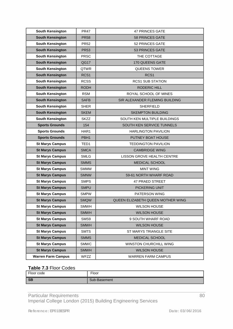
Particular Requirements 80 Imperial College London (2015) Building Engineering Services
Reference: EP01BESPR Date: 03/06/2016
South Kensington PR47 47 PRINCES GATE
South Kensington PR58 58 PRINCES GATE
South Kensington PR52 52 PRINCES GATE
South Kensington PR53 53 PRINCES GATE
South Kensington PRSC THE COTTAGE
South Kensington QG17 170 QUEENS GATE
South Kensington QTWR QUEENS TOWER
South Kensington RCS1 RCS1
South Kensington RCSS RCS1 SUB STATION
South Kensington RODH RODERIC HILL
South Kensington RSM ROYAL SCHOOL OF MINES
South Kensington SAFB SIR ALEXANDER FLEMING BUILDING
South Kensington SHER SHERFIELD
South Kensington SKEM SKEMPTON BUILDING
South Kensington SKZZ SOUTH KEN MULTIPLE BUILDINGS
Sports Grounds 154 SOUTH KEN SERVICE TUNNELS
Sports Grounds HAR1 HARLINGTON PAVILION
Sports Grounds PBH1 PUTNEY BOAT HOUSE
St Marys Campus TED1 TEDDINGTON PAVILION
St Marys Campus SMCA CAMBRIDGE WING
St Marys Campus SMLG LISSON GROVE HEALTH CENTRE
St Marys Campus SMMS MEDICAL SCHOOL
St Marys Campus SMMW MINT WING
St Marys Campus SMNW 59-61 NORTH WHARF ROAD
St Marys Campus SMPS 47 PRAED STREET
St Marys Campus SMPU PICKERING UNIT
St Marys Campus SMPW PATERSON WING
St Marys Campus SMQW QUEEN ELIZABETH QUEEN MOTHER WING
St Marys Campus SMWH WILSON HOUSE
St Marys Campus SMWH WILSON HOUSE
St Marys Campus SMS9 9 SOUTH WHARF ROAD
St Marys Campus SMWH WILSON HOUSE
St Marys Campus SMTS ST MARYS TRIANGLE SITE
St Marys Campus SMMS MEDICAL SCHOOL
St Marys Campus SMWC WINSTON CHURCHILL WING
St Marys Campus SMWH WILSON HOUSE
Warren Farm Campus WFZZ WARREN FARM CAMPUS
Table 7.3 Floor Codes Floor code Floor
SB Sub-Basement
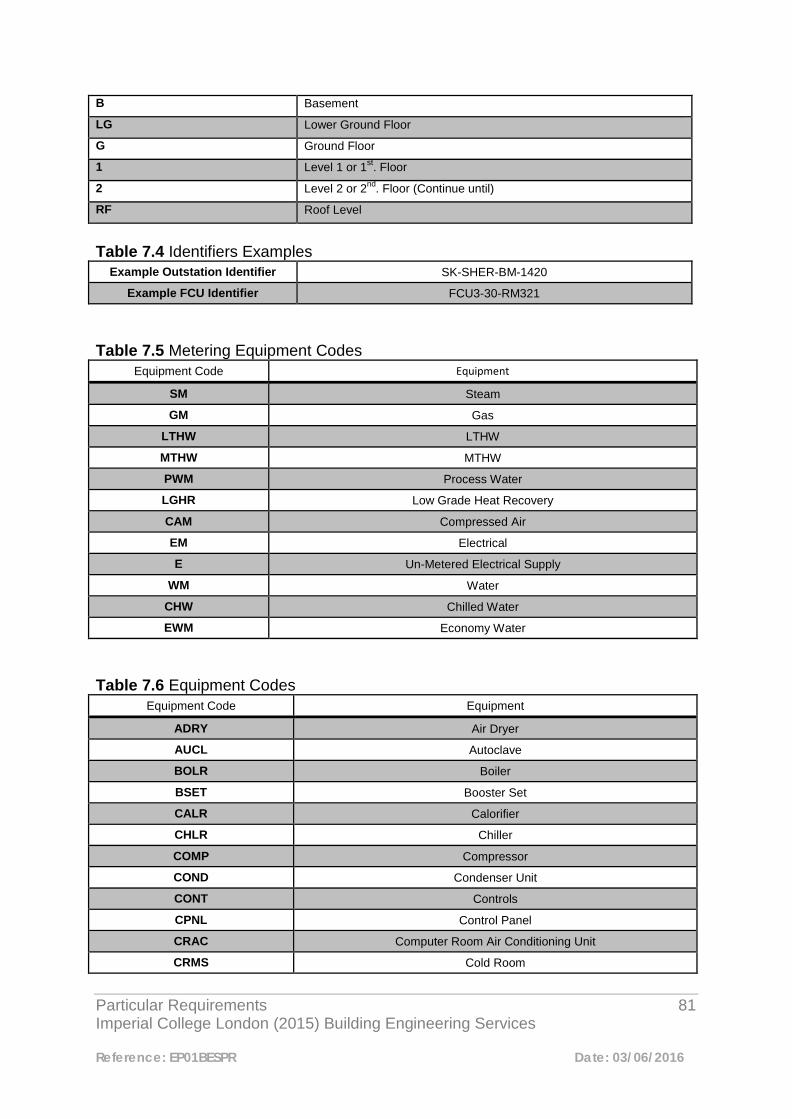
Particular Requirements 81 Imperial College London (2015) Building Engineering Services
Reference: EP01BESPR Date: 03/06/2016
B Basement
LG Lower Ground Floor
G Ground Floor
1 Level 1 or 1st. Floor
2 Level 2 or 2nd. Floor (Continue until)
RF Roof Level
Table 7.4 Identifiers Examples
Example Outstation Identifier SK-SHER-BM-1420
Example FCU Identifier FCU3-30-RM321
Table 7.5 Metering Equipment Codes
Equipment Code Equipment
SM Steam
GM Gas
LTHW LTHW
MTHW MTHW
PWM Process Water
LGHR Low Grade Heat Recovery
CAM Compressed Air
EM Electrical
E Un-Metered Electrical Supply
WM Water
CHW Chilled Water
EWM Economy Water
Table 7.6 Equipment Codes
Equipment Code Equipment
ADRY Air Dryer
AUCL Autoclave
BOLR Boiler
BSET Booster Set
CALR Calorifier
CHLR Chiller
COMP Compressor
COND Condenser Unit
CONT Controls
CPNL Control Panel
CRAC Computer Room Air Conditioning Unit
CRMS Cold Room
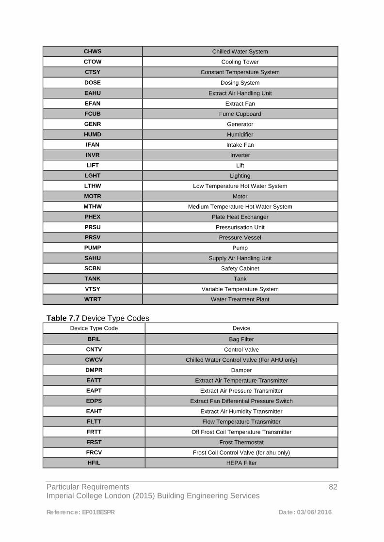
Particular Requirements 82 Imperial College London (2015) Building Engineering Services
Reference: EP01BESPR Date: 03/06/2016
CHWS Chilled Water System
CTOW Cooling Tower
CTSY Constant Temperature System
DOSE Dosing System
EAHU Extract Air Handling Unit
EFAN Extract Fan
FCUB Fume Cupboard
GENR Generator
HUMD Humidifier
IFAN Intake Fan
INVR Inverter
LIFT Lift
LGHT Lighting
LTHW Low Temperature Hot Water System
MOTR Motor
MTHW Medium Temperature Hot Water System
PHEX Plate Heat Exchanger
PRSU Pressurisation Unit
PRSV Pressure Vessel
PUMP Pump
SAHU Supply Air Handling Unit
SCBN Safety Cabinet
TANK Tank
VTSY Variable Temperature System
WTRT Water Treatment Plant
Table 7.7 Device Type Codes
Device Type Code Device
BFIL Bag Filter
CNTV Control Valve
CWCV Chilled Water Control Valve (For AHU only)
DMPR Damper
EATT Extract Air Temperature Transmitter
EAPT Extract Air Pressure Transmitter
EDPS Extract Fan Differential Pressure Switch
EAHT Extract Air Humidity Transmitter
FLTT Flow Temperature Transmitter
FRTT Off Frost Coil Temperature Transmitter
FRST Frost Thermostat
FRCV Frost Coil Control Valve (for ahu only)
HFIL HEPA Filter
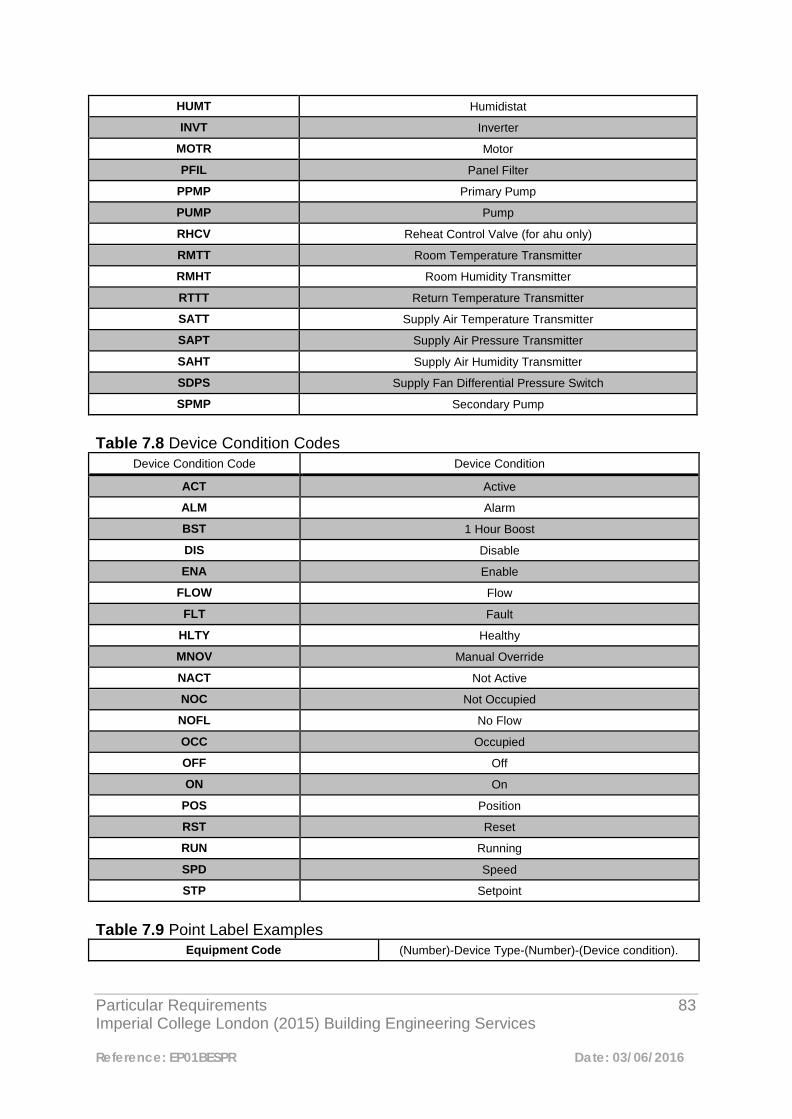
Particular Requirements 83 Imperial College London (2015) Building Engineering Services
Reference: EP01BESPR Date: 03/06/2016
HUMT Humidistat
INVT Inverter
MOTR Motor
PFIL Panel Filter
PPMP Primary Pump
PUMP Pump
RHCV Reheat Control Valve (for ahu only)
RMTT Room Temperature Transmitter
RMHT Room Humidity Transmitter
RTTT Return Temperature Transmitter
SATT Supply Air Temperature Transmitter
SAPT Supply Air Pressure Transmitter
SAHT Supply Air Humidity Transmitter
SDPS Supply Fan Differential Pressure Switch
SPMP Secondary Pump
Table 7.8 Device Condition Codes
Device Condition Code Device Condition
ACT Active
ALM Alarm
BST 1 Hour Boost
DIS Disable
ENA Enable
FLOW Flow
FLT Fault
HLTY Healthy
MNOV Manual Override
NACT Not Active
NOC Not Occupied
NOFL No Flow
OCC Occupied
OFF Off
ON On
POS Position
RST Reset
RUN Running
SPD Speed
STP Setpoint
Table 7.9 Point Label Examples
Equipment Code (Number)-Device Type-(Number)-(Device condition).
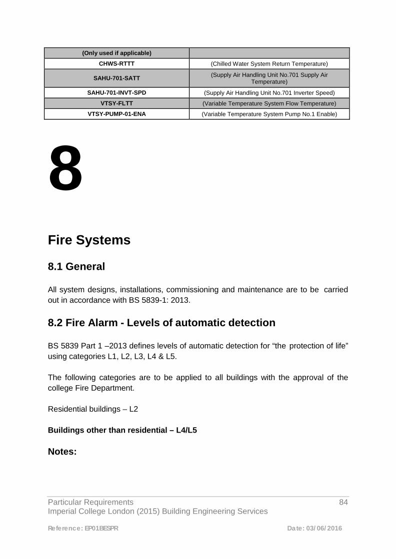
Particular Requirements 84 Imperial College London (2015) Building Engineering Services
Reference: EP01BESPR Date: 03/06/2016
(Only used if applicable) CHWS-RTTT (Chilled Water System Return Temperature)
SAHU-701-SATT (Supply Air Handling Unit No.701 Supply Air Temperature)
SAHU-701-INVT-SPD (Supply Air Handling Unit No.701 Inverter Speed)
VTSY-FLTT (Variable Temperature System Flow Temperature)
VTSY-PUMP-01-ENA (Variable Temperature System Pump No.1 Enable)
8
Fire Systems 8.1 General All system designs, installations, commissioning and maintenance are to be carried out in accordance with BS 5839-1: 2013. 8.2 Fire Alarm - Levels of automatic detection BS 5839 Part 1 –2013 defines levels of automatic detection for “the protection of life” using categories L1, L2, L3, L4 & L5. The following categories are to be applied to all buildings with the approval of the college Fire Department. Residential buildings – L2 Buildings other than residential – L4/L5 Notes:
Particular Requirements 85 Imperial College London (2015) Building Engineering Services
Reference: EP01BESPR Date: 03/06/2016
1. No installation shall be provided with a level of protection less than that defined by level L2 for residential buildings or L4 for non- residential buildings. 2. Prior to commencing the design of an installation the design concept shall be agreed with the College Fire Office. This may lead to the application of an L5 level of protection “designed to satisfy a specific fire safety objective” which exceeds the requirements and/or application of an L2 or L4 category. 8.3 Control and Indicating Equipment (CIE) The Fire Services Office, and Fire and Security Engineer (on behalf of the Engineering Manager) are to be consulted regarding the signals that are required for all when new CIE. 8.4 Fire Alarm Control and Indicating Panel Addressable Panels shall be selected from the Morley ZX5e range, complete with internal power supply unit and Yuasa battery. All panels to be selected to operate using Apollo ‘XP95’ protocol. 8.5 Conventional Systems The specifications of conventional systems are to be approved by the Imperial Fire and Security Engineer. 8.6 Standby Supplies (Battery Back-up) Stand by batteries should be of a type having a life of at least four years. Labels should be fixed to all batteries indicating their date of installation. The capacity of the battery should be sufficient to maintain the system in operation for at least 24hours, after which sufficient capacity should remain to operate all fire alarm devices for at least 30 min. 8.7 Devices for use in Addressable Systems 8.7.1 Point Detectors Point detection devices shall be selected from the Apollo ‘XP 95’ range.

Particular Requirements 86 Imperial College London (2015) Building Engineering Services
Reference: EP01BESPR Date: 03/06/2016
Prior to selecting devices, the designer shall consult with the College Chief Fire Officer and Fire and Security Engineer with regard to the possible application of ‘Discovery’ devices from within the XP95 range. Note: Automatic detectors will be put on “silent sounders”. There will be a 5 minute delay to allow for alarm verification before a full audible evacuation is signaled. Any activation of a Manual Call Point will override this delay. For clarification please consult the Imperial Fire and Security Engineer and Fire Office. 8.7.1.1 Remote Indicators Remote indicators will be required for concealed detectors at all times. These should be labeled with the Device Panel, Loop and Device Number. 8.7.1.2 Labelling All devices are to be labeled as follows, Panel** Loop** Device*** e.g. 1.02.004 8.7.2 Manual Call Points Manual call points shall be Type A and selected from the Apollo XP 95 range. 8.7.3 Input/Output Units Input/output units shall be selected from the Apollo XP 95 range. 8.7.4 Beam Detectors Beam detectors shall be selected from the Fireray range of devices. 8.7.5 Aspirating Fire Detection Systems shall be designed using the Xtralis VESDA system.

Particular Requirements 87 Imperial College London (2015) Building Engineering Services
Reference: EP01BESPR Date: 03/06/2016
8.8 Sounders 8.8.1 Voice Enhanced Voice enhanced sounders shall be selected from the Vimpex ‘Voice Enhanced’ range, complete with associated control equipment.
8.8.2 Bells Bells shall be selected from the Fulleon electronic range. 8.9 Visual Alarm Devices 8.9.1 Beacons Beacons shall be selected from the Fulleon Xenon range complete with a red lens. 8.10 Magnetic Door Retainers Magnetic door retainers shall be selected from the Vimpex 24 volt range with a minimum of 500N holding force, complete with associated power supply unit. 8.11 Plant Override Test Switch Plant override test switch type is to be agreed with the Imperial Fire and Security Engineer. 8.12 Manual Break Glass Override Switch (Magnetically retained secure doors) Manual break glass override switches shall be coloured green, and shall release the associated door by operating a double pole switch protected by a clear plastic element. Switches shall be KAC K20DGS-11 8.13 Speech Dialler
Particular Requirements 88 Imperial College London (2015) Building Engineering Services
Reference: EP01BESPR Date: 03/06/2016
The use and type of speech dialers are to be approved by the Imperial Chief Fire Officer and Fire and Security Engineer. 8.14 Vibrating Pillows Where vibrating pillows are required to alert sleeping occupants with a hearing disability, the specification shall be agreed with the College Chief Fire Officer and Imperial Fire and Security Engineer. 8.15 Vibrating Paging System Vibrating paging system shall be WASOL Deafwatch. 8.16 Fire Alarm/Access Control Interface All doors with electric locking systems shall include a provision to allow the door to be opened in the event of a fire alarm or other emergency situation. The following options are available, and are listed in order of preference: -
• A handle on the secure side of the door, which overrides the electric locking mechanism. (This method is not suitable for swipe-in/swipe-out situations or where the door is for emergency use only).
• An interface between the locking system and the fire alarm system with a
manual break glass override mounted local to the door. Option 2 above brings together two areas of responsibility, those parties involved with the access control system and those parties involved with the fire alarm system. For clarity, the demarcation between these parties shall be as follows: -
• Access control system installer – shall supply and install the locking system etc. and green break glass override.
• Fire alarm system installer – shall supply and install the fire alarm system
double pole interface and make the necessary connections to isolate the door lock mechanism phase and neutral.
Prior to making the connections referred to above, the fire alarm installer shall advise the Imperial Estates Fire and Security Engineer.

Particular Requirements 89 Imperial College London (2015) Building Engineering Services
Reference: EP01BESPR Date: 03/06/2016
8.17 Connection and Commissioning The following procedure applies to the connection of all additions and/or amendments to the College’s fire alarm and fire detection systems. The management and maintenance of the College’s fire detection and alarm systems is the responsibility of Estates Facilities. Prior to undertaking any works to extend or amend the College’s fire detection and alarm systems, the proposals shall be submitted for approval, to the Head of Maintenance and College Chief Fire Officer, and in addition, to the College’s Fire and Security Engineer. Only the College’s appointed maintenance provider may make connections to the existing fire detection and alarm network, or any part thereof. Therefore, the contractor appointed to undertake the installation of any extension and/or amendment to the existing system, is required to employ the College’s appointed maintenance provider to undertake the final connections to the College’s ‘live ‘network, and for re-commissioning to ensure that the whole system performs correctly on completion. The connection and commissioning works undertaken by the maintenance contractor is a project cost and will be deemed to be included in the installing contractor’s tendered price. The contractor shall issue the necessary Commissioning Certificates in accordance with the current edition of BS 5839 for the whole of the works on completion. To initiate the connection and commissioning works described above, the installation contractor shall submit Form EP.03 (Fire and Security Alterations) in accordance with the instructions set out on the form. The form may be downloaded from the Estates Projects/Engineering/Project Procedure Forms section of the College’s website. 8.18 Record Drawings Morley Visualeyez Graphical Monitoring System (South Kensington campus only) From an operational, project and maintenance perspective, it is essential to be able to access an up to date drawing for any part of the College’s fire alarm network. To achieve this, it is necessary to maintain a ‘master set’ of controlled copies that are updated whenever a change is made to the network. The College’s ‘master set’ of drawings are held in the Visualeyez Graphic System. Only the College’s appointed maintenance provider may amend the master set of record information. Therefore, the contractor appointed to undertake the installation of any extension and/or amendment to the existing system, is required to employ the
Particular Requirements 90 Imperial College London (2015) Building Engineering Services
Reference: EP01BESPR Date: 03/06/2016
College’s appointed maintenance provider to record any changes to the information held in the Visualeyez System. Updating of the master set of record drawings is a project cost and will be deemed to be included in the installing contractor’s tendered price. For all other campus’s, fire alarm record documentation is to be addressed as part of the requirements for O&M Manuals as set out in the College Project Procedures. In all cases, where existing drawings are required these will be provided by the Engineering Team. They can be obtained via the Fire and Security Engineer. 8.19 Log Books All changes/additions to existing installations shall be entered as appropriate in to the Building Fire Log Book. Log books are kept adjacent to each Building Main Fire Alarm Panel enclosed within an approved (Red) enclosure. Where a Log Book is not available, one shall be provided by the installing contractor and issued to the Fire Office; all relevant information shall be entered as appropriate. The following details are required within the Log Book: 1. The name of the responsible person; Premises Management. 2. Brief details of maintenance arrangements. 3. Dates and times of all fire alarm signals (regardless of whether the signal has
resulted from the operation as a result of a test, fire drill or genuine fire); If the fire alarm signal has resulted from the operation of a manual call point or fire detector, the device and location shall be recorded;
4. Causes, circumstances surrounding and category of all false alarms; 5. Dates, times and types of all tests. 6. Dates, times and types of all faults and defects; 7. Dates and types of all maintenance (e.g. service visit or non-routine attention). 8. Variations. Where work is carried out to the Fire Alarm System the contractor will record all required information (as above), it is the responsibility of the person managing the contractor to ensure that this is carried out. 8.20 Temporary Fire Detection

Particular Requirements 91 Imperial College London (2015) Building Engineering Services
Reference: EP01BESPR Date: 03/06/2016
With the approval of the Chief Fire Officer, temporary modification of existing point fire detectors in any given area may be made, providing suitable AFD devices are installed to meet the environmental conditions and the CIE and Visualeyez GUI are updated to clearly reflect the changes made. It will also be the responsibility of the initiator to reinstate the original AFD devices and update the CIE and Visualeyez GUI accordingly. All configuration and programming changes required to achieve the above shall be undertaken by the Imperial incumbent maintenance provider. The cost of this shall be covered by the initiator.

Particular Requirements 92 Imperial College London (2015) Building Engineering Services
Reference: EP01BESPR Date: 03/06/2016
9
Security Systems 9.1 Access Control System 9.1.1 General All Systems to be installed to BS EN 50133-7 9.1.2 Types 9.1.2.1 Primary Access Control High/Medium security doors requiring an audit trail and full door status monitoring via Lenel Onguard Software i.e. Perimeter doors, corridor doors, Red and Amber coded access doors. Hardware and Software Manufacturer: LENEL Systems International Reader Types: Protocol (ISO 14443A-3) 1) IE500-1090-3010 • MIFARE Sector Reader READ-ONLY MT/Wiegand standard housing, with
buzzer (output format LENEL WG36) 5-12VDC @ 200mA with the ability to read MIFARE Classic 1k 4Byte and 7Byte UID cards.
• Reader RED and GREEN LED Indicators to be configured: flashing RED in standby mode, flashing GREEN on a valid read.
• All Readers are to be labelled with the appropriate ASSET CODE supplied by Imperial ID Card Office.

Particular Requirements 93 Imperial College London (2015) Building Engineering Services
Reference: EP01BESPR Date: 03/06/2016
2) LENEL-826S121NN • Keypads are to be used where pin and card is required. 9.1.2.2 Secondary Access Control Medium/Low security doors requiring an audit trail via Lenel Onguard software but no door status monitoring, i.e. specific FM and ICT doors, internal doors 1) Aperio E100 Escutcheon Option 1 • Aperio Wireless Battery operated locking without door monitoring. Din Handle set
with Union deadlocking night latch for internal single leaf timber/steel doors. • E100 handle providing free egress at all times from the inside and controlled
access via integrated RFID reader from the outside. In addition, mechanical cylinder specified to provide key override in emergency.
• Aperio E100 Standard Mifare RFID Handle set 8mm spindle 40/50mm U Handle Single Piecing, Include Mercury Communication Hub. See Aperio notes below.
• Union 2C25 Din Size Auto dead latching night latch 55mm backset
• Single Europrofile Cylinder – To Imperial College Key. See Aperio notes below. Option 2 • Aperio Wireless Battery operated locking no door monitoring. Scandinavian
Handle set c/w ASSA 8762 Deadlocking night latch and snib function (Free passage from both sides of door) for single leaf timber/steel doors.
• E100S handles providing free egress at all times from the inside and controlled
access via integrated RFID reader from the outside. In addition, Mechanical cylinder specified to provide key override in emergency. ASSA 8762 lock auto deadlocks every time the door shuts to provide maximum security when door is closed and using separate security key can hold latch back to allow free passage.
• Aperio E100S Standard Mifare RFID Handle set 8mm spindle 40/50mm U Handle
Single Piecing, include Mercury enabled communication hub. See Aperio notes below.
• ASSA 8762 Mortice Lock case with snip function 50mm backset

Particular Requirements 94 Imperial College London (2015) Building Engineering Services
Reference: EP01BESPR Date: 03/06/2016
• Single Scandinavian Cylinder – To Imperial College Key. See Aperio notes
below. 2) Aperio C100 Escutcheon (By Approval by the Imperial fire and Security Engineer Only) • Aperio Wireless Battery operated locking, no door monitoring. Electronic Cylinder
Europrofile with Union 2C21 Sashlock. Free passage from both sides of door via lever handles (Unlocked) for single leaf timber/steel doors.
• C100 Cylinder providing free egress at all times from the inside knob and
controlled access via integrated RFID reader from the outside. Door latching only once unlocked and opened via handles both sides.
• Aperio C100 Standard Mifare RFID Single Scandinavian/Europrofile cylinder
include Mercury enabled communication hub. Union 2c21 Sashlock. Union J1000 Series Round Rose Return to Door Lever handle set.
Option 3 • Low security doors requiring a coded lock with no audit trail or door status
monitoring. i.e. Internal office doors. To use Codelocks CL5010 / CL5010 BB
Aperio Notes: 1) Aperio 1-8 Hub to be installed if there is no capacity available within an existing
1-8 Hub within the door vicinity. 2) Aperio C100 and E100 Escutcheons cannot be used on perimeter doors or
security coded doors. 3) When ordering Aperio E100 Escutcheon cylinders, specify the building number,
as per the Imperial Aperio Building Schedule, cylinder length and type. Contact the Imperial Fire and Security Engineer for detailed information.
9.1.3 Primary Access Control Hardware Specification 9.1.3.1 Power Supplies
Particular Requirements 95 Imperial College London (2015) Building Engineering Services
Reference: EP01BESPR Date: 03/06/2016
All Primary Access Controlled Doors will require a 240v non-switched; neon indicated fused spur fitted adjacent to supply the Local Power Supply Unit (PSU). All Power Supplies must be UL Listed and dedicated for Security Access Control use. The PSU must be able to deliver 5A @13.6 VDC total output loading with recharging of standby batteries to be considered an addition to the output load. The Power Supply output will then be sub-divided into five 1A outputs each individually fused and used to supply a single device i.e. Lenel IDC and associated sounder and locking device. Door controllers and PSU’s are to be housed in a suitably sized enclosure with cooling and ventilation to manufacturer’s recommendations. Provision for a minimum of 4 hours standby battery backup on mains failure is required, with batteries being contained in the same enclosure. 9.1.3.2 Local Door Controllers LNL-1320 Controllers are to be used and sited adjacent to door address one. Where a door is connected to door address two, the maximum distance from LNL-1320 to door is not to exceed 20M. 9.1.3.3 Intelligent System Controller (ISC) LNL-3300 Intelligent System Controllers are to be used if there is no capacity on an existing controller. Door controllers are to be housed in a suitably sized enclosure with cooling and ventilation to manufacturer’s recommendations. Provision for a minimum of 4 hours standby battery backup on mains failure is required.
1) A LENEL LNL-8000 Star Multiplexer Board is to be installed with Each LNL-3300 ISC, for distribution of the RS485 communication network.
2) Intelligent System Controllers are to be installed within college approved ICT CWC rooms.
3) Reader Licences. When installing 10 or more readers a Lenel 64 Reader Licence is to be supplied and installed onto the college Security Access Control System.
4) All system wiring to be as per LENEL requirements. 9.1.3.3 Connectivity Connection of LENEL ISC devices onto the college central Security Access Control Server is to be via the college LAN. Cabling to a local network socket will be required although the preferred method would be to install a network socket within the ISC enclosure. The device will need to be set to DHCP and power cycled to pick up the registered Host Name and IP address.
Particular Requirements 96 Imperial College London (2015) Building Engineering Services
Reference: EP01BESPR Date: 03/06/2016
To allow ICT to register the device the following information is required to be sent to ICT service desk via the Fire and Security Engineer, • Location of Panel • Type of Controller • MAC Address of the Device • Serial Number of the Device • Network Socket Number 9.1.4 Locking Devices ASSA/ABLOY EL560/561: Series electronic locks are the preferred locking method and are to be fitted where possible (Euro Cylinders, anti-bump/anti-snap). Magnetic Locks: To be fitted on double doors within a full width transom, they must have a minimum holding force of 1200lbs with a minimum of 2M ground clearance. Magnetic Locks are to be secured adequately using thread lock and safety straps for the armature plates. ASSA/ABLOY EL512/513: Locks are to be used when Magnetic locks cannot be used and the door does not form part of a fire escape route. TRIMEC ES 8000 V-Locks: To be used on swing doors or glass doors where required. EFF-EFF-351U: Locks are to be used on any internal door forming part of an escape route when Maglocks cannot be used. Notes: 1) Euro Cylinders for electric locks not covered under APERIO Lock Schedule are to
be ordered via the College security (Locks and Keys) Department. 2) All locks fitted onto Final Fire Escape and Fire doors are to unlock whilst under a
side load. For Estates Facilities type areas e.g. Plant Rooms, Lift Motor Rooms and Roof Doors specific cylinders are to be used, these are currently held by, Imperial Fire and Security Engineer. Egress Buttons: High Impact, Green Dome Type egress buttons marked “Press to Exit” to be used when Magnetic Locks or Electronic Locks are fitted at the head of

Particular Requirements 97 Imperial College London (2015) Building Engineering Services
Reference: EP01BESPR Date: 03/06/2016
the door. When ASSA/ABLOY EL-560 locks are installed the request to exit input signal should come from the operation of the exit handle. Green Emergency Break Glass Units (BGU’s): KAC or Specialized Security Type to be used. Break Glass Units marked “Emergency door Release” are to be fitted unless Electronic Locks are used that have a Non-Electronic handle for exit. All BGU’s are to be fitted with a clear plastic cover except perimeter doors which require Alarmed Stopper Covers. Note: There are three requirements on activation of a BGU device: • Both legs of the lock power are to be mechanically isolated. • Activation of a local sounder, silenced by replacing the BGU glass. • Priority event signalled on the LENEL Onguard Access Control events screen.
9.1.5 Door Monitoring: All Fire Escape and Access Controlled Doors are to be monitored either via the access control system or a local Intruder alarm system for alarm notification. Sentrol Door Contacts are to be used. The system type is to be agreed with the Imperial Fire and Security Engineer. Local Door Alarm Sounders are to be installed at each door location to activate on a door forced and door held open alarm, they are to be White Fulleon Askari Compact (RS 530-5990) type. The sound created from this must not conflict with the local Fire Alarm sound. Sounder dip switches to be Set at 01010. Note: All Monitored Doors are to be connected to the security access control system. 9.1.6 Key Override Switches Asec 3E0669-1L double pole, maintained and key retrievable are to be used. 9.1.7 Final Exit Fire Doors
Particular Requirements 98 Imperial College London (2015) Building Engineering Services
Reference: EP01BESPR Date: 03/06/2016
Fire Door locking mechanisms are to be discussed with Security and The Fire Office, the door is to include the following Electronic Lock + Local Sounder + BGU with Stoppa cover + Fire Alarm Connection + Monitored 9.1.8 Additional Alarm Points All additional alarm points e.g. Fire Doors, Panic Buttons or Intruder Alarm Systems are to be connected to the access control system via LNL-1100 input Boards and are to be fully supervised connections. Final Fire doors also require a LNL-1200 Output board to be used in conjunction with the LNL-1100 Input board. 9.1.9 Fire Alarm Connections Connection (via a Local I/O Unit) to the local Fire Alarm System is required when locks are fitted without egress handles or when read in and read out systems are used or if specifically requested by the Imperial Fire Office. An Adaptable Box enclosing lock connections is to be installed for access by others to connect into. This is to be labelled “Interface Connections”. Please see the Fire section of this document for further information. When connecting locks through a Fire I/O please be aware that the contact rating is 1amp, If lock surges are to be above this then relays are to be fitted to avoid damage to the units. 9.1.10 Commissioning The following procedure applies to the connection of all additions and/or amendments to the College’s Lenel Access Control System. The management and maintenance of the College’s Access Control System is the responsibility of the maintenance section of the Estates Facilities and Property Management Division. Prior to undertaking any works to extend or amend the College’s system, the proposals shall be submitted for information, to the Security Team, and in addition to the College’s Fire and Security Engineer, Engineering Team. Only the College’s appointed maintenance provider may commission additional devices onto the System. Therefore, the Project Manager/additional works initiator is required to employ the College’s appointed maintenance provider to undertake the commissioning to ensure that the whole system performs correctly on completion. To

Particular Requirements 99 Imperial College London (2015) Building Engineering Services
Reference: EP01BESPR Date: 03/06/2016
initiate the commissioning works described above, the installation contractor shall submit Form EP.03 in accordance with the instructions set out on the form. The form may be downloaded from the Estates Projects section of the College’s website. Note: As above all proposed amendments to the College’s Security Systems are to be approved by Security Support Services and the Fire and Security Engineer. This will require the submission of The Fire and Security System – Permit to Work Document, this shall be completed by the installing company. 9.1.11 Badging Station Printers To be agreed with Imperial Fire and Security Engineer 9.2 CCTV Systems 9.2.1 Introduction Cameras are to be discussed with the Fire and Security Engineer and specified on an individual requirement basis with the minimum capabilities listed below. Cameras are to be labelled with the appropriate Asset Tag Number supplied by the Fire and Security Engineer. • Internet Protocol • POE Compatible • ONVIF Compliant. • Edge Storage Capable • DHCP Compatible • Hostname Compatible 9.2.2 General All Systems to be installed to BS EN 50132-7 9.2.3 Camera Type

Particular Requirements 100 Imperial College London (2015) Building Engineering Services
Reference: EP01BESPR Date: 03/06/2016
Vandal Resistant Dome Type Cameras (Surface or Flush Mount) External General Areas: DVTEL CM-6204-21-I DVTEL CM-6204-11-I DVTEL CB 6208-11-I DVTEL CB 6208-21-I Internal Areas viewing through External Doors/Windows (Fluctuating Light/Contrast Levels): DVTEL CM-6024-11-I DVTEL CM-6024-21-I Axis M3024-LVE Internal General Areas: DVTEL CM-3102-01-I DVTEL CM-3102-11-I DVTEL CM-6024-11-I DVTEL CM-6024-21-I Where External, Pan, Tilt and Zoom cameras are required: DVTEL CP-4221-201 Axis Q6045-E- optical Zoom x 20
Where standard (Box Type) cameras are required, types to be agreed with the Fire and Security Engineers. Connection is to be via the College LAN. Cabling to a local network socket will be required although preferably a network socket will be installed within 5m of the camera location. To allow ICT to register the unit the following information is required and sent to ICT service desk via the Fire and Security Engineer,

Particular Requirements 101 Imperial College London (2015) Building Engineering Services
Reference: EP01BESPR Date: 03/06/2016
• Location of Camera. • Type of Camera. • MAC Address of the unit. • Network Socket Number. The Camera will need to be set as DHCP and power cycled so that the unit picks up the registered IP address. 9.2.4 Camera lenses Auto-iris and Lens field of view to suit area, Varifocal where possible. IR Corrected Varifocal lenses are to be used where required. 9.2.5 Camera Power Supply All cameras are to be POE compliant; where High POE is required POE Injectors are to be used. 9.2.6 Recording and Monitoring Systems Dvtel NVMS platform is to be used. The specified servers are to be installed within a suitable locked, vented and fanned enclosure. Connection is to be via the College LAN. Cabling to a local network socket will be required although preferably a network socket will be installed within the enclosure. To allow ICT to register the unit the following information is required and sent to ICT service desk via the Fire and Security Engineer, • Location of Panel. • Type of NVR. • MAC Address of the unit. • Network Socket Number. The NVR will need to be set as DHCP and power cycled so that the unit picks up the registered IP address. Where a Remote Monitoring Console is required a Dvtel USS Edge Client is to be used, this is to be connected to the LAN. Note:

Particular Requirements 102 Imperial College London (2015) Building Engineering Services
Reference: EP01BESPR Date: 03/06/2016
CCTV Cameras are to be connected to existing local recording units; if there are no available inputs or the additional camera will negate the required 31 day archiving a new unit will be required. Please seek advice from the Fire and Security Engineer. 9.2.7 Monitors Flat Screens Monitors are to be LED Monitors, Minimum Resolution 1080p. Minimum Contrast Ratio of 10000:1 and Minimum Brightness of 300cd/m2. Note: All proposed amendments to the Colleges Security Systems are to be approved by Security Support Services and the Fire and Security Engineer. This will require the submission of The Fire and Security System – Permit to Work Document, this shall be completed by the installing company. The systems are required to be commissioned and handed over to The Fire and Security Engineer for acceptance. 9.3 Intruder Alarms 9.3.1 General All Systems to be installed to BS EN 50131 System Security Grading and Environmental Classifications are to be set by the Security Team. 9.3.2 Intruder Alarm Panels 9.3.2.1 Intruder Alarm Panel Type UTC ATS Panels are to be used; these are to be integrated into the College’s Lenel OnGuard Software via the college LAN.

Particular Requirements 103 Imperial College London (2015) Building Engineering Services
Reference: EP01BESPR Date: 03/06/2016
9.3.1.2 Detectors Dual-tec type detectors are to be used, detectors with Anti-masking are to be used for Grade 3 systems and upwards. 9.3.1.3 Connectivity Intruder Alarm Panels are to be connected to the College’s Lenel Alarm Monitoring System via a (TCP/IP) Ethernet Module Connection is to be via the College LAN. Cabling to a local network socket will be required although preferably a network socket will be installed within 5m of the panel location. To allow ICT to register the unit the following information is required and sent to ICT service desk via the Fire and Security Engineer, • Location of Panel. • Type of Panel. • MAC Address of the unit. • Network Socket Number. The Panel will need to be set as DHCP and power cycled so that the unit picks up the registered IP address. 9.3.3 Panic, Lone Worker and Man Down Alarms Scantronic 700 Series 868.6625MHz Transmitters & Receivers to be used when wireless Panic, Emergency and Lone Worker Buttons are required. These are to be wired to a Local Intruder Alarm System or via the Lenel Access Control System for monitoring. 9.3.4 Scaffold Alarms All Scaffolding Towers will be required to have an Intruder Alarm installed with notification of Alarms to go to Sherfield Security Desk via a speech dialer. 9.3.5 Intercoms/Help-Points/Tannoys/Vehicles Barrier Control/Disabled Toilet Alarms, Refuge Points and Fire Telephones
Particular Requirements 104 Imperial College London (2015) Building Engineering Services
Reference: EP01BESPR Date: 03/06/2016
Where the above devices are required Commend UK devices are to be used and connected to the existing network infrastructure. The design of the system is to be discussed with the Fire and Security Engineer before an order is placed. BPT or Comelit systems can be installed where a basic one to one intercom system is required. General Notes: 1) All system Operational Requirements are to be agreed with Security Team and
the fire and Security Engineer. 2) All Cabling is to be labeled at every 4m noting what the cable is being used for
e.g. Access Control, CCTV, Intruder Alarm or Intercom. 3) All Cables that enter into control boxes are to be protected by suitable glands
/grommets and run through/on suitable permanently fixed containment. 4) External containment is to be galvanized trunking or galvanized tube, if
galvanized tube is used all inspection boxes are to be fitted with gaskets and appropriate precautions to be taken to prevent oxidization.
5) All Circuit Boards etc. are to be permanently fixed into their enclosures. The use of adhesive or adhesive fixings is not permitted.
6) System Manufacturer Installation and Wiring Guides are to be adhered to at all times.
7) All parts of the installation are to comply with the relevant standards. 8) Where Fire compartmentation is breached it is the responsibility of the contractor
to reinstate and certify. 9) The installations of locks are not to impact on the integrity of the fire rating of the
doors.
Particular Requirements 105 Imperial College London (2015) Building Engineering Services
Reference: EP01BESPR Date: 03/06/2016
9.4 Automatic Door Integration with Access Control 9.4.1 General The following sets out the requirements for the Electrical services works to be carried out by the selected Contractor and Specialists. 9.4.2 Operation Operation of the doors shall be controlled by a suitable number of sensors spaced across the width of the door assembly at high level internally and externally. Under normal hours the doors shall operate under control of the sensors. Out of hours operation shall be enabled by the College Security Access Control system (SACS) to be installed by a Lenel Specialist Security Contractor (LSSC), with card readers installed both internally and externally. The door system shall incorporate an Uninterruptible Power Supply (UPS) to power the door in the event of a mains electrical power failure. The definition of ‘Normal Hours’ and ‘Out of Hours’ shall be determined by Security Operations and programmed via the SACS to suite. 9.4.3 Controls
9.4.3.1 Doors The door activation and safety features shall include intelligent electronic sensing devices to ensure the door responds as people approach. The use of threshold and side screen safety shall be incorporated to meet the requirements of BS 7036. Typically sensors shall be mounted on the top of the door frame internally and externally to ensure satisfactory response and operation of the door assembly as people approach the door. The door system shall also incorporate wiring and fixed terminals to enable the College SACS, to be provided and installed by the LSSC to interface satisfactorily with the sliding door system controls. The functions and terminals to be provided by the Door Manufacturer for connection to and operation by the SACS shall be as listed below:
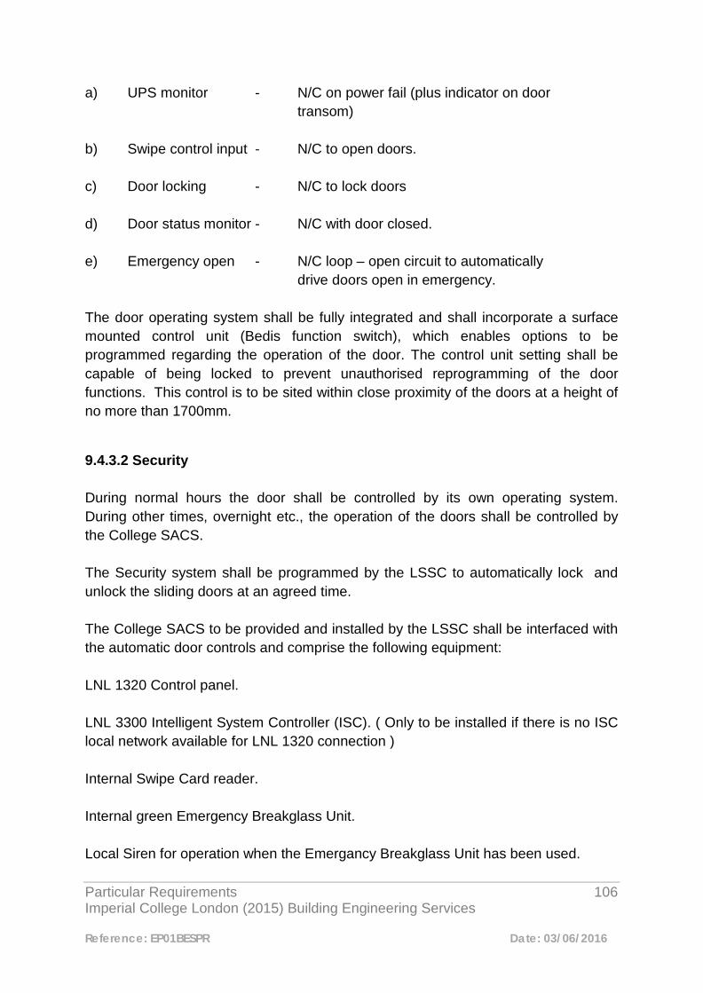
Particular Requirements 106 Imperial College London (2015) Building Engineering Services
Reference: EP01BESPR Date: 03/06/2016
a) UPS monitor - N/C on power fail (plus indicator on door transom) b) Swipe control input - N/C to open doors. c) Door locking - N/C to lock doors d) Door status monitor - N/C with door closed. e) Emergency open - N/C loop – open circuit to automatically drive doors open in emergency. The door operating system shall be fully integrated and shall incorporate a surface mounted control unit (Bedis function switch), which enables options to be programmed regarding the operation of the door. The control unit setting shall be capable of being locked to prevent unauthorised reprogramming of the door functions. This control is to be sited within close proximity of the doors at a height of no more than 1700mm.
9.4.3.2 Security During normal hours the door shall be controlled by its own operating system. During other times, overnight etc., the operation of the doors shall be controlled by the College SACS. The Security system shall be programmed by the LSSC to automatically lock and unlock the sliding doors at an agreed time. The College SACS to be provided and installed by the LSSC shall be interfaced with the automatic door controls and comprise the following equipment: LNL 1320 Control panel. LNL 3300 Intelligent System Controller (ISC). ( Only to be installed if there is no ISC local network available for LNL 1320 connection ) Internal Swipe Card reader. Internal green Emergency Breakglass Unit. Local Siren for operation when the Emergancy Breakglass Unit has been used.

Particular Requirements 107 Imperial College London (2015) Building Engineering Services
Reference: EP01BESPR Date: 03/06/2016
External Swipe Card reader. Cat 5e data point for ISC network connection. (If LNL 3300 is required). Use of an appropriate SACS Card shall enable the door controls to operate during the secure period and enable access to or egress from the Building. Operation of the green Emergency Breakglass Unit (EBGU) shall automatically open the doors and permit egress from the Building under emergency circumstances. The Swipe Card readers and green EBGU shall be mounted at 900mm above floor level to suit Wheelchair users in positions to be agreed on site. The Specialist Security Contractor shall allow for all control wiring, final connections as shown on the drawing, testing and commissioning of the completed system. Installations are to be commissioned by the installing contractor then passed to the Main Contractor/Imperial College who are to appoint the current maintenance contractor to program the installation on to the Main College System. The installing contractor is required to include costs for all such commissioning and programming work. All works shall be carried out in accordance with the College Standard Specifications and Particular Requirements.
9.4.3.3 CCTV Installation The Specialist Security Contractor, shall supply and install complete a new CCTV camera in a position to be agreed on site. All works shall be carried out in accordance with the College Standard Specifications and Technical Policy Statements. The camera shall be of an appropriate type (Seek guidance from Fire and Security Engineer) ceiling mounted and enclosed within a suitable Housing. The camera shall provide images enabling the Recognition of an individual entering through the Doors. The Specialist Security Contractor shall allow for testing and commissioning of the completed system.
9.4.3.4 Fire Alarms
Particular Requirements 108 Imperial College London (2015) Building Engineering Services
Reference: EP01BESPR Date: 03/06/2016
The control systems of the automatic doors shall be interfaced to the Building Fire Alarm systems. The Fire Alarm Interface(s) shall be provided and installed complete by the College appointed fire alarm contractor. The College appointed fire alarm maintenance contractor will carry out the testing and commissioning of the Fire Alarm works. The green EBGU contacts shall be wired in series with the Fire Alarm interface unit contact thus forming a normally closed loop. During a Fire Alarm incident or the operation of the green EBGU the normally closed loop shall be opened and the sliding doors shall automatically operate and remain in the open position until the Fire Alarm system or EBGU has been re-set. 9.4.3.5 Uninterruptible Power Supply (UPS) To ensure satisfactory operation of the automatic door assembly should an Electrical power failure occur a battery powered UPS is included by the door Manufacturer incorporated into the door head assembly to provide sufficient power to operate the doors for a specific period of time. An indicator will be provided in the underside of the door controls cover that will illuminate when the door system is operating on the batteries. The status of the mains Electrical supply shall be monitored by the SACS and during a loss of the mains supply the SACS shall register an alarm in Security via the Alarm Monitoring Screen. 9.4.4 Commissioning
9.4.4.1 Attendance All Contractors, Specialist Contractors and Manufacturer’s representatives shall attend site at the same time during the testing and commissioning of the completed door and Security systems installation.
9.3.4.2 Documentation All installation works, testing and commissioning shall be fully completed before the installation is offered for demonstrating to the Project Manager or his representatives. The following commissioning data shall be provided prior to the demonstration: a) Electrical services Test Certificates to BS 7671. b) Certification that the Security system is complete and meets the requirements of the Specification complete with all programming details.
Particular Requirements 109 Imperial College London (2015) Building Engineering Services
Reference: EP01BESPR Date: 03/06/2016
c) Commissioning Certificates for the Fire Alarm system. d) Certification that the door system is complete and operates to Specification.
9.4.4.3 Tests The following tests shall be certified as having been carried out: a) Door operation under normal conditions including safety features and all functions of the Bedis panel. b) Emergency operating of the door by use of: i) Green emergency breakglass unit. ii) Fire Alarm interface. (Door should remain open when the audible alarm is cancelled) Note: If it is not convenient to operate the Fire Alarm system the cable cores may be disconnected at the Fire Alarm interface relay for the purposes of this demonstration. Notification must be made however to the Building Manager and Fire Officer for the satisfactory operation of the doors under fire conditions to be witnessed during the very next Fire Alarm test. c) Power failure – observe satisfactory operation of doors and indicator illuminated. Alarm satisfactorily relayed to Sherfield Security via the College monitoring system. d) Verification of the College Security system operation: i) Door locking and unlocking under timed programming. ii) Operation of swipe card functions. iii) Door open alarm functions to Sherfield Security. iv) CCTV operation. After submission of the satisfactory test results the Contractors, Specialist Contractors and Manufacturers shall demonstrate the same to the Project Manager or his representatives.
Particular Requirements 110 Imperial College London (2015) Building Engineering Services
Reference: EP01BESPR Date: 03/06/2016
9.4.5 Record Documentation
9.4.5.1 The Contractor, Specialist Contractors and Manufacturers shall provide to the Project Manager 3 No. copies of all operating instructions, commissioning data, servicing instructions and “As Installed” Record Drawings and wiring diagrammatics of the completed works.
Particular Requirements 111 Imperial College London (2015) Building Engineering Services
Reference: EP01BESPR Date: 03/06/2016
9.5 Electronic Security Systems in Hazardous or Sensitive Areas 9.5.1 Introduction The following sets out minimum requirements. Specific arrangements for each individual project are to be discussed and agreed with the College Security Department, Safety Department and Fire and Security Engineer. The yellow, amber and red colour coding described below is detailed in the College Code of Practice entitled ‘Controlling access to hazardous or sensitive areas’. This is available online at the Safety Dept website. 9.5.2 Yellow coded areas This includes general laboratory areas such as most chemistry labs or most Containment Level 2 biological laboratories. It also can include such areas as workshops or autoclave suites.
9.5.2.1 Alarm Systems - Intrusion and Hold-up Systems No dedicated system is usually required. Doors to the Building / Floor are to be monitored via the Security Access Control System (SACS). No Hold up system is required.
9.5.2.2 Access Controlled Doors Primary Access Control is to be installed on Entrance Doors to Building and Entrance Doors to the Suite/Floor.
9.5.2.3 Closed Circuit Television (CCTV) CCTV is to be sited at all Main Entrances to the building, Operational Requirement for the Camera will be for the purpose of recognition. 9.5.3 Amber and Red coded areas Red coded areas include very high security or very high risk areas such as Containment Level 3 biological labs or irradiator rooms. Amber coded areas are high security or high risk areas and can include the clean corridor areas of Containment Level 3 suites, CBS corridor areas and plant rooms.
Particular Requirements 112 Imperial College London (2015) Building Engineering Services
Reference: EP01BESPR Date: 03/06/2016
9.5.3.1 Alarm Systems - Intrusion and Hold-up Systems The requirement and extent of an Intruder Alarm System is to be determined by the Security and the Safety Department. All systems are to be installed as per BS EN50131 -1:2006 + A1:2009, Grade 3. This is to include the following: Control and Indicating Equipment – Main Control Panel to be sited within the suite in a suitable location, remote keypad to be sited adjacent to the Main Entrance/Exit Door for setting and unsetting of the system. Signaling and Warning Devices – Connection to the College Lenel SACS is required by way of Lenel LNL1100 input module using supervised connections. Level of Detection Devices – Opening of and penetration through external doors plus trap protection as well as special consideration to high-risk items/areas. Hold up (Panic) Alarms are to be installed adjacent each exit door and connected to the College SACS via LNL1100 input module using supervised connections. All I&HAS events signaled via the College SACS must have the highest priority and include an acknowledgeable text box with clear instruction on required actions. Lone Worker Alarms are to be made available to all Lab users (type to be discussed with the Imperial Safety Department and the Fire and Security Engineer). 9.5.3.2 Access Controlled Doors Primary Access Control is to be installed on Entrance Doors to Building and Entrance Doors to the Suite/Floor. A lobby to the suite is to be formed with access control to be fitted on both doors programmed to operate as an interlock, Pin and Proximity readers are to be used. Electronic Locks such as Abloy EL560 fail secure locks are to be used. Note These doors are not to unlock on the activation of the Fire Alarm System.
9.5.3.3 Closed Circuit Television (CCTV) CCTV is to be sited at all Main Entrances to the building, Operational requirement for the Camera will be for the purpose of recognition. CCTV is to be sited to cover the Entrance and Exit to the suite, installed to enable identification.
Particular Requirements 113 Imperial College London (2015) Building Engineering Services
Reference: EP01BESPR Date: 03/06/2016
A monitor is required within the lobby to show the image of the camera on the outside of the unit, this is to enable staff to see that their exit route is clear. CCTV Cameras that are required for inside the suite as well as the Entrance and Exit cameras are to be connected to a dedicated system from within the suite, backed by UPS with a minimum back up time of 20minutes. This system is to be connected to the College LAN, with access available to the Security Department as well as access as required by the Lab users using Dvtel Video Management Viewing Software. 9.5.4 Areas covered by the Anti-Terrorism (Crime and Security) Act (Labs are to include the following plus any special requirements as requested by the CTSO)
9.5.4.1 Alarm Systems - Intrusion and Hold-up Systems Intruder Alarm Systems are to be installed as per BS EN50131 -1:2006 +A1:2009, Grade 3. This is to include the following: Control and Indicating Equipment – Main Control Panel to be sited within the suite in a suitable location, remote keypad to be sited adjacent to the Main Entrance/Exit Door, setting of the system is to be via the door contact programmed to set on final door setting and unsetting of the system is to be actioned by a valid read of the Access Control Reader. Signaling and Warning Devices – Connection to the College Lenel SACS is required by way of Lenel LNL1100 Input Module using supervised connections. Level of Detection Devices – Opening of and penetration through external doors plus trap protection as well as special consideration to high risk items/areas Hold up (Panic) Alarms are to be installed adjacent each exit door and connected to a Lenel LNL1100 Input Module using supervised connections. All I&HAS events signaled via the College SACS must have the highest priority and include an acknowledgeable text box with clear instruction on required actions. Lone Worker Alarms are to be made available to all Lab users (type to be discussed with the Imperial Safety Department and the Fire and Security Engineer).
Particular Requirements 114 Imperial College London (2015) Building Engineering Services
Reference: EP01BESPR Date: 03/06/2016
9.5.4.2 Access Controlled Doors Primary Access Control is to be installed on Entrance Doors to Building and Entrance Doors to the Suite/Floor. A lobby to the suite is to be formed with access control to be fitted on both doors programmed to operate as an interlock, Pin and Proximity readers are to be used. Electronic Locks such as Abloy EL560 fail secure locks are to be used. These doors are not to unlock on the activation of the Fire Alarm System
9.5.4.3 Closed Circuit Television (CCTV) CCTV is to be sited at all Main Entrances to the building, Operational requirement for the Camera will be for the purpose of recognition. CCTV is to be sited to cover the Entrance to the suite; Operational requirement for the Camera will be for the purpose of identification. A monitor is required within the lobby to show the image of the camera on the outside of the unit, this is to enable staff to see that their exit route is clear. CCTV that is required for inside the suite as well as the Entrance and Exit cameras are to be connected to a dedicated system from within the suite, backed by UPS with a minimum back up time of 20minutes. This system is to be connected to the College LAN, with access available to the Security Department as well as access as required by the Lab users using Dvte l Video Management Viewing Software. Note Where SR3/4 rated security doors are required these will be subject to enhanced electronic locking methods, the Specification of which is to be agreed with the Imperial Safety Department and Fire and Security Engineer.
Particular Requirements 115 Imperial College London (2015) Building Engineering Services
Reference: EP01BESPR Date: 03/06/2016
Mechanical
Particular Requirements 116 Imperial College London (2015) Building Engineering Services
Reference: EP01BESPR Date: 03/06/2016
1 Design Criteria 1.1 Design Parameters for Air Conditioning and Comfort Cooling 1.1.1 System Selection
This section of the Particular Requirements document shall be read in conjunction with the Imperial College London “Building Temperature Protocol” (BTP). Where the provision of air conditioning or comfort cooling is required in accordance with the BTP, chilled water systems shall be the default option. It is not the College's policy to use DX based split or variable refrigerant volume cooling systems except where prior approval has been given by way of an Exception Report. Applications for a relaxation of the College chilled water policy shall in the first instance be submitted to the Engineering Manager. For parameters relating to air conditioning loads see paragraph below – 1.2.6 Air Conditioning Load Calculations 1.2 Design Criteria All Imperial College London engineering systems shall be designed in accordance with the criteria set out below:-

Particular Requirements 117 Imperial College London (2015) Building Engineering Services
Reference: EP01BESPR Date: 03/06/2016
1.2.1 Internal & External Design Conditions for Winter & Summer (With Cooling)
1.2.1.1 External Design Conditions Summer: 31°C db, 20.5°C wb
35°C db for selection of air cooled heat rejection
Winter: -4°C db, 100% saturated for building heat loss. -4°C db for air handling frost coil selection -15°C db for low ambient chiller operation
1.2.1.2 Internal Design Conditions for Summer & Winter (occupied hours) Room Type Winter Design
Temp Summer Design Temp
Humidity
Office/Write-Up Areas
20°C ± 2°C 24°C ± 2°C Uncontrolled
Laboratory See note 1 below See note 1 below See note 4 below Lecture Theatre 20°C ± 2°C 24°C ± 2°C Uncontrolled Workshop See note 1 below See note 1 below Uncontrolled CWC Rooms See note 5 below See note 5 below See note 5 below Computer room 20°C ± 2°C 24°C ± 2°C Uncontrolled Bedrooms (Halls of Res)
20°C ± 2°C See note 2 below N/A
Toilets 18°C N/A N/A Corridors & Stairwells
18°C N/A N/A
Storerooms See note 3 below N/A N/A Notes: 1. As per BTP, based on user requirements, but summer design internal
temperature not to be lower than 22°C. 2. Bedrooms would normally be expected to rely on natural ventilation as a means
of reducing summertime temperatures. 3. Design temperature for storerooms should be based on user requirements,
otherwise design to 16°C for winter heating. 4. Requirements for humidity to be confirmed by end users.

Particular Requirements 118 Imperial College London (2015) Building Engineering Services
Reference: EP01BESPR Date: 03/06/2016
5. For temperature and humidity requirements for CWC rooms please refer to ICT Network Infrastructure Standards document which can be found on the following link:-
http://www3.imperial.ac.uk/pls/portallive/docs/1/42925701.PDF 1.2.3 Ventilation 1. Toilet Ventilation Extract: 10 air changes per hour Supply: 8 air changes per hour 2. Fresh Air Provision 10 litres/second minimum per person based upon the stated occupancy densities. Laboratory areas shall be designed to achieve a minimum of 6 air changes per hour based on full fresh air. Individual laboratory room types identified within particular room datasheets and their identified ventilation rates will take precedence, along with the pressure required relative to any adjoining spaces. Outdoor air sources will be located away from external sources of pollution. Security aspects will be considered. Outdoor air to be filtered to better than F7 standard of BS EN 779. 1.2.4 Internal Noise Criteria Air borne noise or vibration received from engineering systems plant and equipment by any mechanism shall not exceed the following noise rating criteria:- General office accommodation in open plan: NR 38 Laboratories: NR 40 Toilet accommodation, stairs, lobbies: NR 45 Reception Areas and entrance foyers: NR 40 The above criteria assume a noise contribution due to the plant and systems operating alone. 1.2.5 Air Conditioning Load Calculations
2. Cooling Loads In general, air conditioning/comfort cooling systems shall be designed to accommodate the following cooling loads:-

Particular Requirements 119 Imperial College London (2015) Building Engineering Services
Reference: EP01BESPR Date: 03/06/2016
Lighting: As design load Small power (office areas): As design load Small power (laboratories): Refer to individual laboratory room type identified
within the particular room datasheets. Occupants: 90 W sensible/50 W latent per person 3. Air Infiltration Summer: 0.5 air changes per hour Winter: 1.0 air change per hour 1.2.6 Future Capacity Designers shall set out the margins that have been applied in deriving the cooling load and the relationship with the proposed installed cooling plant capacity. In particular, the:
• Cooling load calculation margin • Fan, pump and pipe heat gain/loss allowance
A minimum of 20% future capacity above the base cooling load calculations shall be allowed - inclusive of the above allowances. 1.2.7 Fabric Protection The set-point for the protection of building fabric shall be between 12°C and 15°C. 1.2.8 Refrigerants The primary refrigerant to be used in cooling systems shall be selected following a review of the factors set out below. Refrigerants shall be selected from the following list unless otherwise approved.
• R134A, R404a, R407C and R410a Natural refrigerants shall only be used with the express permission of the Director of Facilities and Property Management following a thorough review of the impact.
• Carbon dioxide • Ammonia
Particular Requirements 120 Imperial College London (2015) Building Engineering Services
Reference: EP01BESPR Date: 03/06/2016
• Hydrocarbons 1.2.9 Air and Water Cooled Heat Rejection Water cooled heat rejection is to be avoided where possible due to the potential for legionnaires disease, higher operating costs and use of water. Air cooled heat rejection shall be designed to the following criteria:
• Air on temperature 35 C db taking into account any discharge air recirculation • Maximum refrigerant condensing temperature 50° C
1.2.10 Water Storage Domestic water storage capacity shall be based on guidance given in the CIBSE Guides for the appropriate building type and occupancy density. All installations shall comply with Water Supply (Water Fittings) Regulations and TWA requirements 1999. All laboratories shall be provided with separate, dedicated water systems in accordance with the Water Regulations and British Standards. 1.2.11 Lighting Please refer to Electrical, Section 4. 1.2.12 Fire Detection & Fire Alarms Please refer to Electrical, Section 8.
Particular Requirements 121 Imperial College London (2015) Building Engineering Services
Reference: EP01BESPR Date: 03/06/2016
2
General Specification for Air Handling Units 2.1 Introduction Packaged air handling units (AHU) shall incorporate all the components necessary to provide an efficient and effective source of air distribution, i.e. fans, filters, coils, heat recovery etc. AHUs shall be sized to take into account all key factors including specific fan power, air volume, heating/cooling requirements, humidity control (where applicable), space availability and noise levels. Units shall be selected to provide the required duty at optimum performance and efficiency and shall include clean and dirty filter automatic sensing and fan speed adjustment. (See Appendix 2.19 for sketch for the arrangement of typical AHU). 2.2 Construction Air handling units shall be constructed in accordance with BS EN 1886: 2007 AHUs Mechanical Performance AHU casings shall be “Pentapost” type construction, double skinned steel sheet and thermally and acoustically insulated The external surfaces of air handling units shall be finished in “Plastisol” type plastic coating or alternative of proven equivalent performance. All internal surfaces of AHUs are liable to be affected by moisture, i.e. cooling coils, humidifiers etc, shall be treated with an anti-corrosion finish.

Particular Requirements 122 Imperial College London (2015) Building Engineering Services
Reference: EP01BESPR Date: 03/06/2016
Where units are to be located externally, these shall be fully weatherproofed and shall include raked tops for rain run-off. AHUs shall conform to the following criteria as stated in BS EN 1886:2007:-
• Thermal bridging – Class T2
• Thermal bridging factor – Class TB2
• Casing strength – Class D1
2.3 Fans The fan section of air handling units shall normally contain a centrifugal fan/motor, direct drive or belt driven, mounted on an anti-vibration isolated frame. The fan section shall be designed to allow for easy removal of the fan and motor for maintenance/replacement. Fans shall be forward curved, double inlet double width, for total fan static pressures up to 450pa. Fans shall be backward curved where the total fan static pressure exceeds this figure. 2.4 Motors Fan motors shall be of high efficiency class IE2 rating to BS EN 60034.30:2014. Motors shall be compatible with inverter drives with the drives being mounted remotely to the air handling unit. Motors shall be selected to operate at a frequency range of between 45Hz and 60Hz. 2.5 Heating Coils Air handling units shall incorporate a low temperature hot water frost coil, main heater battery and, where required, a re-heater coil. Any deviation to this arrangement will require an Exception Report to be submitted for approval.

Particular Requirements 123 Imperial College London (2015) Building Engineering Services
Reference: EP01BESPR Date: 03/06/2016
Where low temperature hot water is the heating source the heating coils shall be constructed from solid drawn copper tube expanded into continuous plate type fins of either aluminium or copper. Where steam is the heating medium then coils shall be constructed from mild steel tubes, welded throughout, with mild steel fins and protected from corrosion. Heating coils shall have a face velocity not exceeding 2.5 m/s. Notes: 1) Coil face velocity may need to be reduced further to meet the requirements of
Part L (Conservation of Energy) of the Building Regulations. 2) Electric heater batteries shall only be used where a LTHW constant temperature
heating supply or steam supply is not available. Electric heater batteries shall be thyristor modulated control type for good temperature stability. Where an electric heater battery is considered to be necessary, an Exception Report shall be submitted for approval.
2.6 Cooling Coils Cooling coils shall be constructed from solid drawn copper tube expanded into continuous plate type fins of either aluminium or copper. Sealing devices shall be provided at the tops and bottoms of coils to minimise air by-pass and water carry over. Eliminators shall also be incorporated to prevent water carry over. The face velocity across the cooling coils shall not exceed 2.5 m/s. Note: Coil face velocity may need to be reduced further to meet the requirements of Part L (Conservation of Energy) of the Building Regulations. 2.7 Frost Protection of Air Handling Units To ensure prevention of freezing of wet coils within full fresh air/partial fresh air handling units the following should be incorporated:-
Particular Requirements 124 Imperial College London (2015) Building Engineering Services
Reference: EP01BESPR Date: 03/06/2016
• LTHW frost coil to be installed as part of the AHU package • Lattice type capillary tube frost stat installed upstream of the frost coil Under normal circumstances the frost coil shall be sized to heat the incoming air from -4°C up to +5°C. In the event of a failure of the LTHW circulation system the frost thermostat (set at +4°C) shall, after a “three knocks and out” arrangement, generally initiate the following:- • De-energise the supply fan • Close off the motorised air inlet dampers • Open the frost coil, cooling coil and re-heat coil motorised control valves to
50%. • Generate an alarm to the BEMS The AHU frost thermostat shall be “hard-wired” with manual re-set located on the BEMS panel. See sketch of typical air handling unit arrangement showing preferred location of frost coil and frost thermostat. 2.8 Heat Recovery The energy efficiency of air transfer systems can be improved by the use of heat recovery and is the default arrangement for the selection of all AHUs. Where the designer can demonstrate through life cycle analysis that the additional capital cost of heat recovery cannot be justified, an exception may be permitted, subject to approval of an Exception Report. The main types of heat recovery systems that are currently commercially available are:-
• Thermal wheel
Particular Requirements 125 Imperial College London (2015) Building Engineering Services
Reference: EP01BESPR Date: 03/06/2016
• Plate heat exchanger (recuperator)
• Run-around coil system Where thermal wheels are selected as the chosen method for heat recovery these should be controlled by the Building Energy Management System via a Trend inverter. Sufficient access shall be allowed in the design of the air handling unit for ease of cleaning and maintenance of the heat recovery system. 2.9 Control of Air handling Units/Ventilation using Carbon Di-Oxide (CO2) Sensors Consideration shall be given at design stage, as an energy saving measure, to the incorporation of CO2 monitoring to adjust supply air volumes/fresh air content of ventilation systems. Where practical and where proven to be cost effective, the CO2 sensors, in conjunction with inverter controlled fans, dampers etc shall modulate the system supply air to the space in response to the CO2 levels and hence the level of occupancy. It should be noted that CO2 sensors shall operate to a set point of 650 ppm. 2.10 Air Filtration Air handling unit air filter types and efficiencies shall be as required to meet the necessary design criteria. Primary and secondary air filtration shall conform to BS EN 779: 2012 for filter performance. Primary filtration shall be achieved by the use of high performance disposable pleated panel filters. The primary panel filters shall be G4 rated and tested in accordance with the British Standard referred to above. Secondary filtration shall be achieved utilising high efficiency bag filters which have a large media surface area and therefore, low air resistance. The bag filters shall have minimum rating of F7, with F9 being the preferred option and held in corrosion proof frames.

Particular Requirements 126 Imperial College London (2015) Building Engineering Services
Reference: EP01BESPR Date: 03/06/2016
Where plant space permits, the bag filter section of the air handling unit shall be sufficient length (normally 700mm min) to accommodate the high efficiency, high capacity filters. All filters shall be Eurovent certified and tested to BS EN 1886: 2007 for air leakage and performance. 2.11 Filter Differential Pressure Gauges Air handling units shall be provided with Magnehelic type differential pressure gauges on the filter sections of units of 1 m³/s air volume and above. The Magnehelic gauges as manufactured by Dwyer Instruments shall be selected to provide an appropriate range with the differential pressure measuring in pascals. Gauges shall be appropriately labelled indicating design filter clean and dirty settings. Inclined gauge type manometers shall not be used in the above application. 2.11.1 Typical Gauge Pressure Ranges The Magnehelic gauges shall normally be selected with a pressure range of 0-500Pa which would be suitable for most panel and bag filters. Typical pressure drops for filters with a face velocity of 2 m/s would be as listed in Table 2.1. Table 2.1 Typical Pressure Drops for Filters Type Initial pd (Pa) Average pd (Pa) Recommended Final pd
(Pa)
G4 Panel Filter 41 146 250
F7 Bag Filter 56 254 350
H12 Hepa Filter 180 390 600
As can be seen from the table, where air handling units etc incorporate Hepa filters, the gauge range would need to be increased to cover a pressure differential of 0-1.0kpa.

Particular Requirements 127 Imperial College London (2015) Building Engineering Services
Reference: EP01BESPR Date: 03/06/2016
2.12 Spacing of Fins for Frost Coils and Run-Around Coils Frost coils and run-around coils are not usually protected by filters and with close fin spacing, the coils will block very quickly with dirt and grime. The College approved fin spacing for these coils shall be 6mm (4-5 fins per 25mm). All other air handling unit coils shall be of standard fin spacing. 2.13 Dampers Dampers used in sections of air handling plant shall be of the multi-leaf type. The damper blades shall be constructed to ensure rigidity and prevent distortion and jamming in operation. The blades shall be securely fixed.
Manually and automatically operated dampers shall include a means for clearly indicating externally the position of damper blades. Air leakage through dampers when in the closed position shall not exceed 5% of the maximum design air volume. 2.14 Access Doors Air handling units shall be provided with hinged doors with air seals, to facilitate access to upstream and downstream faces and internal parts of all sections of the plant. Access doors will be 300mm or 600mm wide depending on the size of the AHU and sections to be accessed. 2.15 Viewing Ports and Internal Lighting Viewing ports and internal lighting shall be provided wherever practical, i.e. in larger air handling units, for checking fans, filters and humidifiers. Power to the air handling unit internal lighting shall be served from the local mechanical control panel from which the AHU is served. Viewing ports shall be positioned to allow replacement of lamps.

Particular Requirements 128 Imperial College London (2015) Building Engineering Services
Reference: EP01BESPR Date: 03/06/2016
2.16 Attenuators Attenuators shall be fitted as part of the air handling unit. These shall be sized to achieve the necessary sound level reduction as advised by the acoustic consultant/specialist. 2.17 Condensate Traps Air handling unit condensate traps shall be installed with sufficient trap height to prevent “pulling” of the water seal under the influence of the fan pressure. The following measures shall be adopted to ensure that the traps have a sufficient water seal:-
a) Ensure that air handling units that are installed in plantrooms/roof plant areas are located on concrete/steel plinths to a minimum height of 100mm.
b) Install a trap at the cooling coil condensate drain point of each air handling
unit. The trap shall be constructed from copper pipe and fittings consisting of two tees and removable plugs for inspection, cleaning and, if necessary, priming. The trap shall be configured to maintain a suitable water column that will overcome the fan outlet pressure. (See Appendix 2.20)
As an alternative to the copper pipework trap arrangement, the “table tennis ball” type trap can be adopted. The trap, as manufactured by Swegon, shall be installed to the manufacturer’s recommendations. The AHU condensate drain shall run to fall terminating at a drain point with a suitable trap/air gap. 2.18 Eurovent Certification Air handling units shall only be selected from the Imperial College London approved list of suppliers. Any proposed deviation from this shall only be considered following submission of an Exception Report.
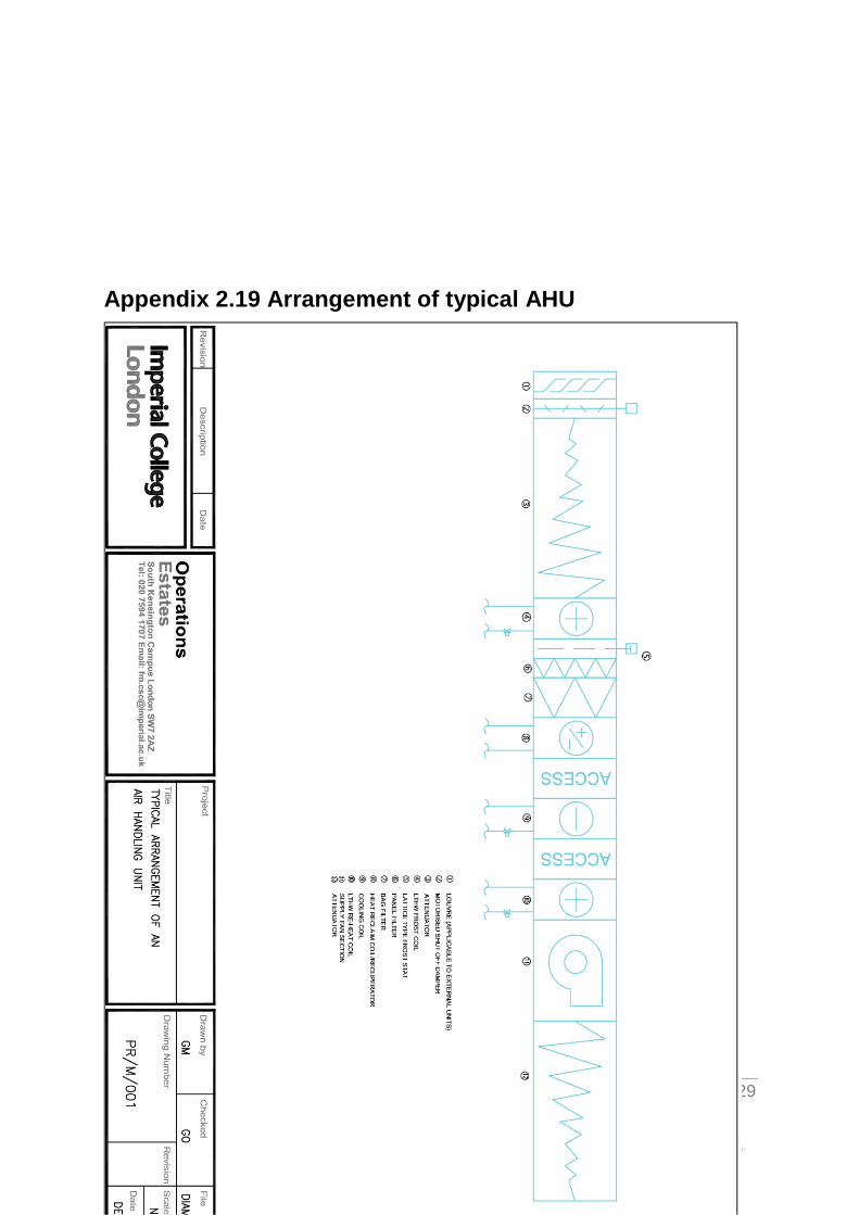
Particular Requirements 129 Imperial College London (2015) Building Engineering Services
Reference: EP01BESPR Date: 03/06/2016
Appendix 2.19 Arrangement of typical AHU
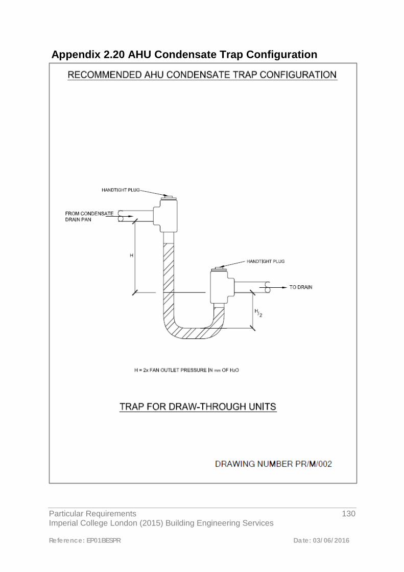
Particular Requirements 130 Imperial College London (2015) Building Engineering Services
Reference: EP01BESPR Date: 03/06/2016
Appendix 2.20 AHU Condensate Trap Configuration
Particular Requirements 131 Imperial College London (2015) Building Engineering Services
Reference: EP01BESPR Date: 03/06/2016
Appendix 2.21 Typical Steam & Condensate Connection to Air Handling Unit Heater Battery
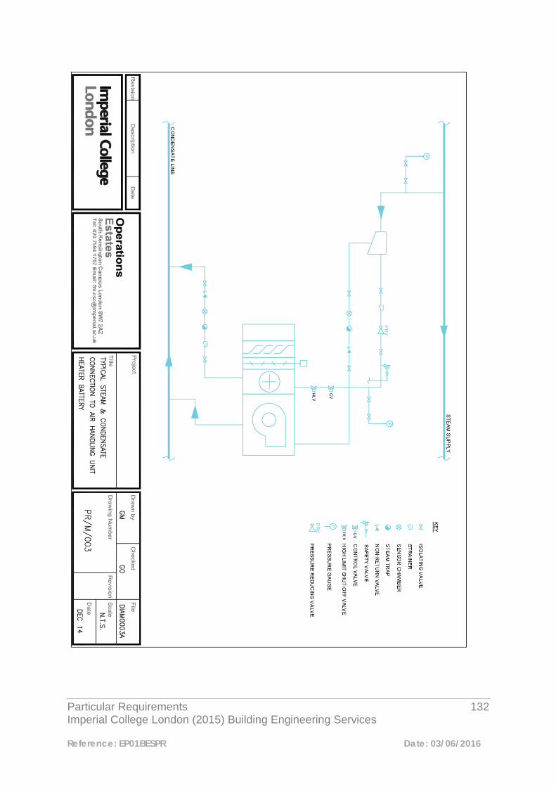
Particular Requirements 132 Imperial College London (2015) Building Engineering Services
Reference: EP01BESPR Date: 03/06/2016

Particular Requirements 133 Imperial College London (2015) Building Engineering Services
Reference: EP01BESPR Date: 03/06/2016
3
Pipework and Ancillaries 3.1 Pipework Materials and Jointing Methods 3.1.1 Introduction This section sets out pipework components, materials, jointing methods and types of thermal insulation etc. that are to be used on Imperial College installations. Equipment integral within a pipeline installation such as pumping equipment, pressurization units, steam system components etc. shall also be selected and installed in accordance with this section of the Particular Requirements document. 3.1.2 Table of Standard Pipework Materials Pipework materials and the types of services they are to be used for are tabulated below:-
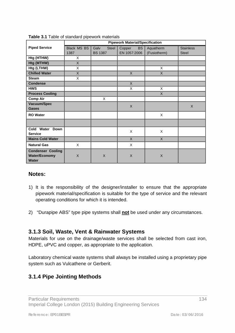
Particular Requirements 134 Imperial College London (2015) Building Engineering Services
Reference: EP01BESPR Date: 03/06/2016
Table 3.1 Table of standard pipework materials
Piped Service Pipework Material/Specification
Black MS BS 1387
Galv Steel BS 1387
Copper BS EN 1057:2006
Aquatherm (Fusiotherm)
Stainless Steel
Htg (HTHW) X Htg (MTHW) X Htg (LTHW) X X Chilled Water X X X Steam X Condense X HWS X X Process Cooling X Comp Air X Vacuum/Spec Gases X X
RO Water X
Cold Water Down Service X X
Mains Cold Water X X
Natural Gas X X
Condenser Cooling Water/Economy Water
X X X X
Notes: 1) It is the responsibility of the designer/installer to ensure that the appropriate
pipework material/specification is suitable for the type of service and the relevant operating conditions for which it is intended.
2) “Durapipe ABS” type pipe systems shall not be used under any circumstances. 3.1.3 Soil, Waste, Vent & Rainwater Systems Materials for use on the drainage/waste services shall be selected from cast iron, HDPE, uPVC and copper, as appropriate to the application. Laboratory chemical waste systems shall always be installed using a proprietary pipe system such as Vulcathene or Gerberit. 3.1.4 Pipe Jointing Methods

Particular Requirements 135 Imperial College London (2015) Building Engineering Services
Reference: EP01BESPR Date: 03/06/2016
In all cases pipe jointing methods shall be appropriate for the service type and the operating conditions of the system. Table 3.2 shows typical jointing methods that would be acceptable for use on the appropriate services on Imperial College campuses:- Table 3.2 Pipework jointing methods Pipe Material Jointing Method Black Mild Steel Screwed, welded, welded flanged, Victaulic etc. Galv Mild Steel Screwed, screwed flanged Aquatherm Hot weld, Electrofusion fittings
Copper
Soldered or brazed fittings. Also press-fit type fittings as manufactured by Pegler Yorkshire or Conex. Press-fit fittings to be restricted to maximum pipe diameter of 54mm. All joints to be accessible, ensuring sufficient access for press-fit tool. Note that Press-fit fittings shall not be used on steam/condense return systems. Compression fittings shall only be used where other methods are not practical/possible, e.g. connecting to a water tank ball float valve.
Stainless Steel Welded joints normally carried out by specialist contractor.
Note: All proprietary pipework and jointing systems such as Victaulic, Aquatherm etc. shall be installed in strict accordance with the manufacturers recommendations. 3.2 Commissioning Sets for Installation on CHW, LTHW & MTHW Heating 3.2.1 General Commissioning sets and regulation valves shall be provided on all hydraulic systems as a means of measuring and balancing flow rates to the design values. Commissioning valves shall be provided in the following locations:-
• Terminal units • Heating coils, cooling coils and heat exchangers • All major pipework branches not in the index circuit
Commissioning stations and regulating valves must be provided with a means of locking the valve in the set position.
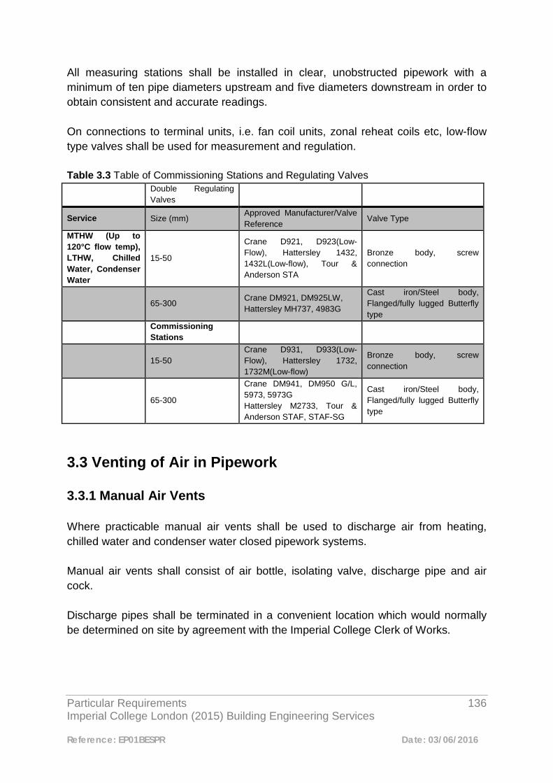
Particular Requirements 136 Imperial College London (2015) Building Engineering Services
Reference: EP01BESPR Date: 03/06/2016
All measuring stations shall be installed in clear, unobstructed pipework with a minimum of ten pipe diameters upstream and five diameters downstream in order to obtain consistent and accurate readings. On connections to terminal units, i.e. fan coil units, zonal reheat coils etc, low-flow type valves shall be used for measurement and regulation. Table 3.3 Table of Commissioning Stations and Regulating Valves
Double Regulating Valves
Service Size (mm) Approved Manufacturer/Valve Reference
Valve Type
MTHW (Up to 120°C flow temp), LTHW, Chilled Water, Condenser Water
15-50
Crane D921, D923(Low-Flow), Hattersley 1432, 1432L(Low-flow), Tour & Anderson STA
Bronze body, screw connection
65-300 Crane DM921, DM925LW, Hattersley MH737, 4983G
Cast iron/Steel body, Flanged/fully lugged Butterfly type
Commissioning Stations
15-50 Crane D931, D933(Low-Flow), Hattersley 1732, 1732M(Low-flow)
Bronze body, screw connection
65-300
Crane DM941, DM950 G/L, 5973, 5973G Hattersley M2733, Tour & Anderson STAF, STAF-SG
Cast iron/Steel body, Flanged/fully lugged Butterfly type
3.3 Venting of Air in Pipework 3.3.1 Manual Air Vents Where practicable manual air vents shall be used to discharge air from heating, chilled water and condenser water closed pipework systems. Manual air vents shall consist of air bottle, isolating valve, discharge pipe and air cock. Discharge pipes shall be terminated in a convenient location which would normally be determined on site by agreement with the Imperial College Clerk of Works.
Particular Requirements 137 Imperial College London (2015) Building Engineering Services
Reference: EP01BESPR Date: 03/06/2016
3.3.2 Automatic Air Vents Where it is not practical to install air bottles, automatic air vents shall be installed. These shall be Flexvent type auto-air vents as manufactured by Flamco Ltd or equal approved. Auto-air vents shall have 15mm inlet and shall be installed with means of isolation utilising a lever ball-valve. Where automatic air vents are to be installed the following shall be taken into consideration:-
• Auto-air vents shall not be installed in areas where a release of water could cause damage to equipment.
• Auto-air vents shall not be installed in concealed areas where leaks can go on
undetected for long periods.

Particular Requirements 138 Imperial College London (2015) Building Engineering Services
Reference: EP01BESPR Date: 03/06/2016
4
Pump Sets and Inverter Drives 4.1 Pump Sets Pumps sets shall be installed in accordance with the sketch located in Appendix 4.3. Pump sets shall be in the form of individual pumps whereby any pump can be removed and maintained allowing the system that it serves to continue to operate using the remaining pump. Duplex pump sets are not permitted. Duplex refers to pump sets whereby a motor cannot be removed without a total isolation/drain-down of the system that it serves. 4.2 Inverters With the exception of glandless “canned rotor” type pumps (covered under the EU energy directive), circulation pumps shall be controlled by separate inverters.
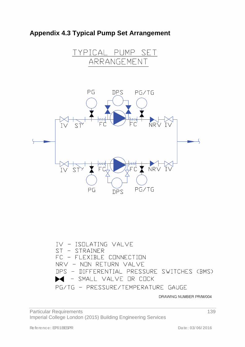
Particular Requirements 139 Imperial College London (2015) Building Engineering Services
Reference: EP01BESPR Date: 03/06/2016
Appendix 4.3 Typical Pump Set Arrangement

Particular Requirements 140 Imperial College London (2015) Building Engineering Services
Reference: EP01BESPR Date: 03/06/2016
5 Pressurisation Units for LTHW Heating, CHW & Process Cooling 5.1 Introduction Then default option is for conventional feed and expansion tanks for the pressurisation of LTHW & chilled water systems. Where it can be demonstrated that this arrangement is not possible or practical and unable to meet the necessary pressure criteria for the application, pressurisation units shall be utilised and selected as indicated below subject to approval of an Exception Report. 5.2 Unit Selection Where mains pressure is adequate for the purpose, the Mikrofill EFD pressurisation unit as supplied by Mikrofill Systems Ltd, or equal and approved, shall be used. Where it is not possible to provide this type of pressurisation unit, these shall generally be selected from the standard range of packaged units provided by approved suppliers, Armstrong Holden Brook Pullen or Grundfos Ltd. The selection of pressurisation units and associated pressure vessels shall be based on an appropriate assessment of the water content of the system and of the system pressure criteria. The cold fill pressure in the water system should be equal to the static pressure + 0.5bar to 1.0bar maximum to suit the application.

Particular Requirements 141 Imperial College London (2015) Building Engineering Services
Reference: EP01BESPR Date: 03/06/2016
5.3 Unit Specification The specified pressurisation unit shall be complete with the following:-
• Duty/standby pumps with manual changeover (Packaged units only)
• Break tank (Packaged units only)
• Pressure vessel
• Quick-fill connection
• High/Low system pressure switches
• Pump trip indication (Packaged units only)
• Common fault alarms to BMS The “Service Due” alarm/cut-out and password protection shall be omitted from the unit control features.
Particular Requirements 142 Imperial College London (2015) Building Engineering Services
Reference: EP01BESPR Date: 03/06/2016
6
Hot and Cold Water Services 6.1 Central Systems The preferred method of raising domestic hot water is to provide a central system comprising of buffer vessels, plate heat exchangers, circulation pumps, controls etc. Shell and tube type calorifiers shall not be installed. 6.2 Minimising Risk of Legionnaires Disease Where new or extended hot and cold water systems are to be provided these shall be strictly in accordance with the recommendations set out in HSE ACoP L8 and CIBSE Technical Memorandum TM13. 6.3 Connection into Existing Hot and Cold Water Service Infrastructure Where there is a requirement to provide new or additional hot and cold water services, the College existing hot and/or cold water network may be extended. The designer/installer shall confirm to the Engineering Manager that there is sufficient capacity in the system prior to connecting to the existing infrastructure. 6.4 Secondary Circulation of Hot Water Services Where a new or extended domestic hot water service is to be provided, pumped secondary return pipework shall be incorporated. Particular care shall be taken at the system design stage to avoid dead-legs and stagnant sections in order to prevent the growth of Legionella.
Particular Requirements 143 Imperial College London (2015) Building Engineering Services
Reference: EP01BESPR Date: 03/06/2016
Only a single pump arrangement shall be acceptable on hot water service return legs to prevent the risk of Legionella growth. The use of self-regulating electric trace heating tape shall not be adopted as an alternative to a secondary circulation system without prior approval of the Engineering Manager. 6.5 Stand-Alone Point-of-Use Hot Water Heaters Where it is not practically possible to use a central system that takes its primary source of heat from the College infrastructure, local “point-of-use” type heaters shall be provided subject to approval. Where this type of system is proposed, an Engineering Exception Report shall be submitted to the Engineering Manager for approval. 6.6 Cold Water Storage Tanks All break tanks and cold water storage tanks shall be constructed of glass fibre reinforced plastic externally flanged sections. Where internally flanged tanks are required because of space restraints etc., these shall be subject to an Engineering Exception Report. Cold water storage tanks shall be complete with all the necessary access hatches, connections, bosses etc. Galvanised tanks or treated ferrous tanks shall not be installed. 6.7 Cold Water Pumping Equipment Cold water booster pumps shall be fully packaged, self-contained units comprising a number of main duty and standby pumps with automatic change-over. The booster pumps and integral control panel shall be mounted on a fabricated steel base plate/frame. The booster pump set shall provide a fault indication only, to the Building Management System.

Particular Requirements 144 Imperial College London (2015) Building Engineering Services
Reference: EP01BESPR Date: 03/06/2016
6.8 System Design All cold water and potable water systems shall be designed in accordance with BS 8558:2015 and BS EN 806: 2005. The complete design, installation, chlorinisation and commissioning procedure shall be carried out in accordance with all current codes of practice and CIBSE guidelines for domestic hot and cold water systems. 6.9 Hot and Cold Water Taps The preferred type of hot and cold water taps are the monobloc single lever type as manufactured by Grohe or equal. Taps shall be complete with a flow limiting, aerating facility to reduce water consumption. Spray type taps shall not be installed as they can create an aerosol effect increasing the risk of infection by Legionella bacteria. 6.10 Thermostatic Mixing Valves The installation of thermostatic mixing valves on hot and cold water supplies shall be restricted to wash hand basins in accessible toilets or where there are likely to be vulnerable people, i.e. young children. 6.11 Hot and Cold Water Services in Laboratories It shall be assumed that all laboratories within the College Estate are classified as high risk under Fluid Category 5 of the Water Regulations 1999. The preferred solution for back-flow prevention of water systems within laboratories shall be the provision of segregated water systems, i.e. laboratory (industrial) hot and cold water services shall be totally segregated from the domestic water services. Where segregation of services is not possible or practicable then Type DC, WRAC approved, pipe interrupters shall be installed subject to submission of an Engineering Exception Report. Where Type DC devices are installed following approval, these shall also be subject to the following proviso’s:-
• Type DC devices shall not be attached to any apparatus that would create a back pressure
Particular Requirements 145 Imperial College London (2015) Building Engineering Services
Reference: EP01BESPR Date: 03/06/2016
• Type DC devices shall not be installed on outlets in Biological and Micro-biological Safety Cabinets
• Outlets in biosafety cabinets shall be fed via Type AA, AB or AD air gaps
Particular Requirements 146 Imperial College London (2015) Building Engineering Services
Reference: EP01BESPR Date: 03/06/2016
7
Condense Drains 7.1 General All condense drains from air handling units and fan coil units shall be installed to drain by means of gravity. The installation of pumped drainage systems shall only be considered following the approval of an Exception Report. Approval shall only be considered following receipt of a detailed submission describing the particular circumstances of the installation, a schematic diagram of the arrangement proposed and details of the proposed pump including manufacture and model. If it is agreed to install condense pumps, the approved arrangement shall include a collection vessel and pump controlled via a float switch, the vessel being of a sufficient size to accommodate the contents of the condense tray plus a safety margin of 25%. If installed on fan coil units, these shall be arranged to shut down on condense pump failure. All condense drains shall be carried out using copper tube to BS EN 1057 – R250 and a trap with an appropriate air gap shall be installed at the connection point to the main drainage system in accordance with ACOP L8.
Particular Requirements 147 Imperial College London (2015) Building Engineering Services
Reference: EP01BESPR Date: 03/06/2016
8
Thermostatic Radiator Valves (TRV’s) and Radiator Lockshield Valves 8.1 Valve Body Thermostatic radiator valve bodies shall be manufactured in accordance with BS EN 215 and shall be of cast brass construction with an “O”-ring seal. Removal of the valve insert shall be achievable while the system is live. The valve body shall be model reference TS 90 as manufactured by Herz Ltd. 8.2 Sensor Heads Sensor heads shall be of the tamper-proof (vandal resistant) type. They shall be of a robust design capable of withstanding considerable force and having no visible means of mounting or setting. Sensors shall be capable of turning down the set temperature by up to 10°C by means of a coin slot operation. Thermostatic heads with remote sensors shall consist of a sensor phial for remote location and a 2.0 metre length capillary tube. The sensor head shall be adjustable and lockable. The thermostatic sensor head shall be model reference Herzcules, as manufactured by Herz Ltd.
Particular Requirements 148 Imperial College London (2015) Building Engineering Services
Reference: EP01BESPR Date: 03/06/2016
8.3 Radiator Lockshield (Return) Valves Radiator lockshield (return) valves shall have a double regulating function with tamper-proof setting by use of a special tool to allow accurate balancing of the system. Removal of the double regulating valve insert shall be achievable while the system is live. Radiator lockshield valves shall be model reference DRT 90 as manufactured by Herz Ltd. 8.4 Maintenance of Thermostatic Radiator Valves The type of TRV that shall be incorporated into the heating system design and specification shall be that which can be easily maintained without the need to install additional isolating valves on the radiator connections. The TRV’s and lockshield valves shall have the ability to be maintained while the heating system is live. Any maintenance of the TRV’s involving removal of the valve inserts shall be carried out live using the manufacturers approved “change-fix” tool. Procurement of the TRV’s shall include a manufacturer’s parts and labour warranty of not less than 5 years to cover defective components.

Particular Requirements 149 Imperial College London (2015) Building Engineering Services
Reference: EP01BESPR Date: 03/06/2016
9
Steam System Components 9.1 Connection into Existing Steam Mains Where new steam supply branch connections are required, these shall be made into the top of the existing steam mains. This is to ensure proper drainage of the steam main. Where connection into the existing system is being considered, it shall be confirmed by site investigation and consultation with the Facilities Management Team and/or the Engineering Team, that sufficient capacity is available. 9.2 Isolating Valves for use on Steam Mains Isolating valves for use on steam mains shall be manufactured from cast steel and selected for the correct system pressures. Isolating valves manufactured from cast iron shall not be used on steam systems under any circumstances. 9.3 Pressure Reducing Valves for use on Steam Mains Pressure Reducing Valves for use on steam pipework systems shall be as manufactured by IMI Bailey Birkett Ltd only.

Particular Requirements 150 Imperial College London (2015) Building Engineering Services
Reference: EP01BESPR Date: 03/06/2016
9.4 Steam Trap Sets Where installed in conjunction with mains drainage points, steam trap sets shall consist of the following components:-
− Isolating valve − Isolating valve − Union − Strainer − Spira: Tec sensor chamber − Trap: Thermodynamic type when externally mounted.
Float type when internally mounted. − Check valve − Union − Isolating valve
Where installed in conjunction with items of plant, steam trap sets shall consist of the following components:-
− Isolating valve − Union − Strainer − Spira: Tec sensor chamber − Trap: Float type when internally mounted − Check valve − Union − Isolating valve
Where four or more trap sets are to be installed, a Spira-Tec Automatic trap monitor shall be provided. A hand held indicator is also to be provided and shall be handed over at the completion of the project. In locations where access is restricted, i.e. underground ducts, ceiling voids etc. and an automatic trap monitor is not provided, a remote test point shall be utilised. Where split coils are installed within Air Handling Units etc. individual trap sets shall be installed on the condense outlet from each coil. For further information on items the above, please refer to the sketch diagrams located in appendices of this section.
Particular Requirements 151 Imperial College London (2015) Building Engineering Services
Reference: EP01BESPR Date: 03/06/2016
9.5 Steam Meters For details of Imperial College approved steam meters, please refer to the metering section of this document.

Particular Requirements 152 Imperial College London (2015) Building Engineering Services
Reference: EP01BESPR Date: 03/06/2016
Appendix 9.6 Steam Pressure Reducing Set
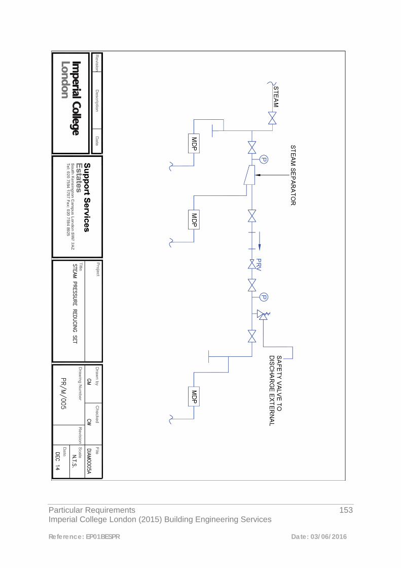
Particular Requirements 153 Imperial College London (2015) Building Engineering Services
Reference: EP01BESPR Date: 03/06/2016
Particular Requirements 154 Imperial College London (2015) Building Engineering Services
Reference: EP01BESPR Date: 03/06/2016
Appendix 9.7 Typical Arrangement of Steam Trap Sets
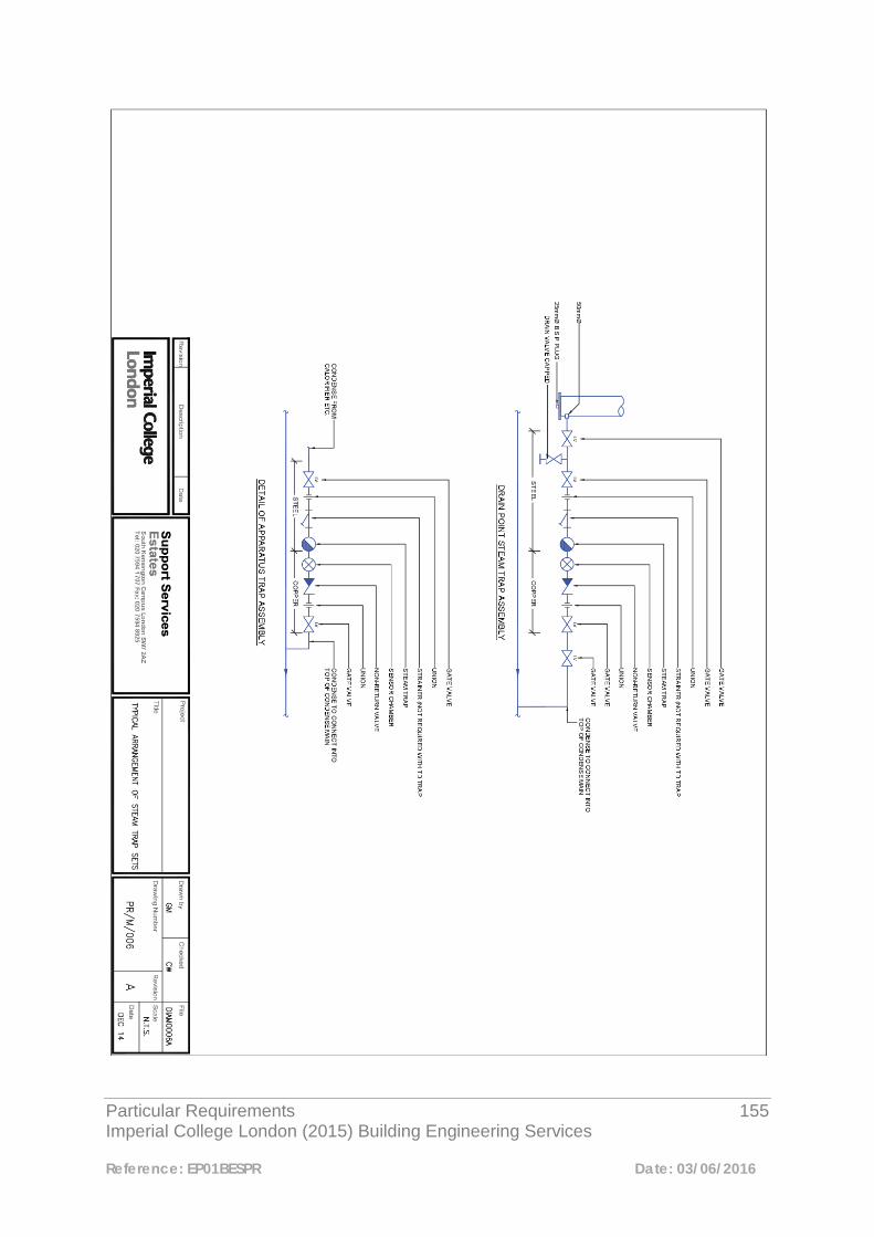
Particular Requirements 155 Imperial College London (2015) Building Engineering Services
Reference: EP01BESPR Date: 03/06/2016

Particular Requirements 156 Imperial College London (2015) Building Engineering Services
Reference: EP01BESPR Date: 03/06/2016
Appendix 9.8 Detail of Steam Main Drainage Point
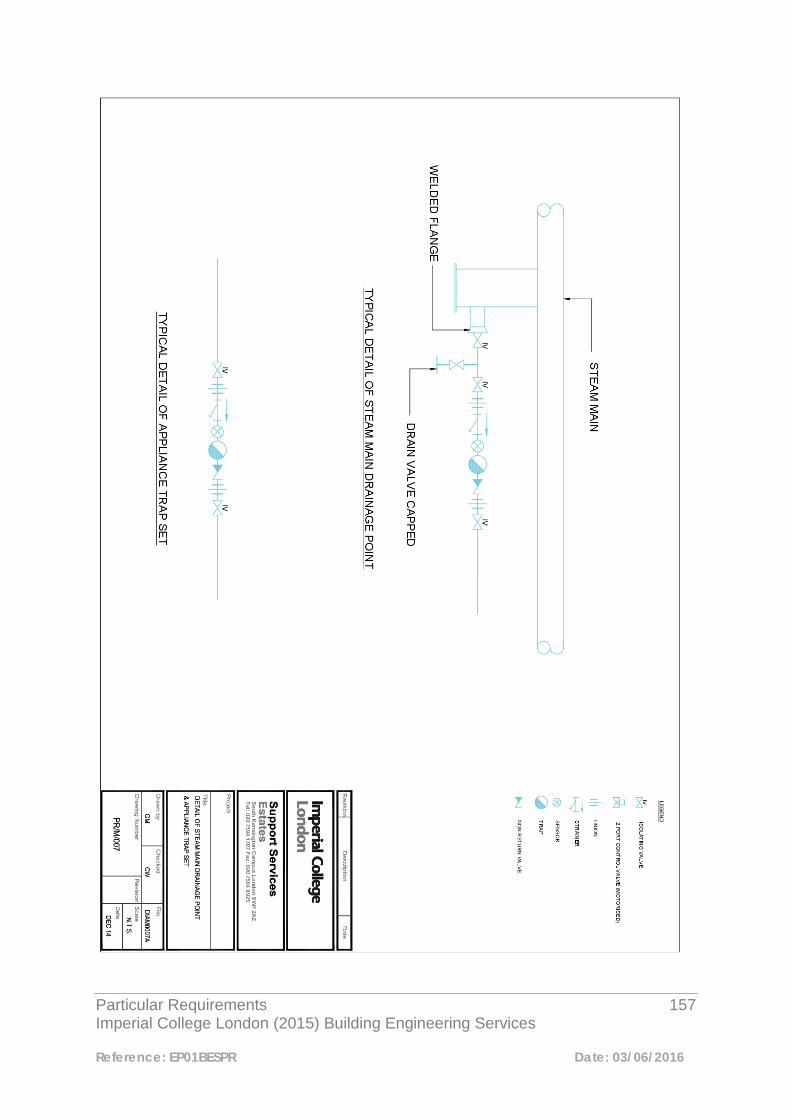
Particular Requirements 157 Imperial College London (2015) Building Engineering Services
Reference: EP01BESPR Date: 03/06/2016
Particular Requirements 158 Imperial College London (2015) Building Engineering Services
Reference: EP01BESPR Date: 03/06/2016
10
Plant Room Drainage Gullies 10.1 General Drainage gullies shall be provided in plant rooms where practically possible. Gullies are required for dealing with leaks, the prevention of flooding of adjacent areas, the drainage of condense from cooler batteries, overflows and relief valves. The gullies shall be connected to sanitary system ventilated stacks. If the provision of a drainage gulley within a plant room is not a practical solution an Exception Report shall be submitted with proposals for an alternative arrangement. The following types of drainage gullies shall be installed in plant rooms to suit the application:-
i) Drainage gulley with removable bell trap – This type of gulley is an open grating cast iron type with a removable “bell” or “bucket” trap. This type of gulley can be accessed from within the plant room to clear blockages by removing the grating and lifting out the bell trap for cleaning. For use where the gulley is only accessible from above.
ii) Open grating cast iron type gulley with trap accessible for cleaning/rodding
via a removable access door on the base of the trap. For use where the gulley is accessible from above or below.
iii) Tundish inlet gullies – This type of gully can be used for the discharge of
temperature and pressure relief valves from boilers and hot water storage vessels etc. This should be done with great care to avoid spillage of water/steam into plant areas etc. It should be noted that where this type of gulley is used a 25mm air gap should be maintained between the top of any tundish inlet and the bottom of any pipe discharging over it. Discharge pipes should never be submerged below the rim of the inlet.

Particular Requirements 159 Imperial College London (2015) Building Engineering Services
Reference: EP01BESPR Date: 03/06/2016
All plant room gullies shall have cast iron or stainless steel bodies and cast iron gratings.
Particular Requirements 160 Imperial College London (2015) Building Engineering Services
Reference: EP01BESPR Date: 03/06/2016
11
Constant Temperature Heating for Primary Air Re-Heat & Zonal Re-Heat 11.1 General Where heating coils have been specified as part of the design to elevate primary air following dehumidification (i.e. chilled beam systems etc.) and also for zonal re-heat, the heating medium for these types of system shall not be derived from the campus wide MTHW system. The South Kensington campus medium temperature hot water heating system shuts down between May and September/October. (Please refer to the Building Manager/Facilities Management Maintenance Team for seasonal shutdowns on other campuses). Therefore, where a constant temperature heating source is required for re-heat coils etc. it should not be derived from the MTHW system. Where re-heat coils are required, the constant temperature circuit serving these shall be derived from the campus wide steam system. The designer shall carry out, as part of the design development, an assessment of the available steam capacity. This assessment should be carried out in conjunction with the Imperial Engineering Team. It should be noted that the site wide steam system shuts down for maintenance during the summer period. This shutdown period is invariably scheduled for two weeks in August. (Confirmation of the exact date of the annual steam shutdown will be issued by Facilities Management).
Particular Requirements 161 Imperial College London (2015) Building Engineering Services
Reference: EP01BESPR Date: 03/06/2016
Where temperature control is critical and reliant on the inclusion of reheat, then measures may need to be incorporated in the design to provide an alternative permanent, or temporary heat source during the steam shutdown period.
Particular Requirements 162 Imperial College London (2015) Building Engineering Services
Reference: EP01BESPR Date: 03/06/2016
12
Fan Coil Units 12.1 Introduction Fan coil units (FCU) shall incorporate all the components necessary to provide an efficient and effective source of air distribution and temperature control. Fan coil units shall be sized to take into account all key factors including specific fan power, air volume, heating/cooling requirements, space availability and noise levels. Units shall be selected to provide the required duty at optimum performance and efficiency. 12.2 Construction Fan coil units shall be blow-through configuration. Fan coil unit casings shall be constructed from galvanized steel of not less than 1.2mm thickness suitably stiffened to minimise drumming and vibration and lined with 12mm open cell acoustic foam. All corners shall be without sharp edges. Casings shall include space for pipework connections and valves and there shall be ready access to the fan, motor, filter, damper, drain pan, pipework connections and valves for maintenance purposes. Condensate trays shall be protected from corrosion and externally lined with 3mm closed cell foam insulation to prevent condensation. 12.3 Fans
Particular Requirements 163 Imperial College London (2015) Building Engineering Services
Reference: EP01BESPR Date: 03/06/2016
The fan assembly shall incorporate a double inlet double width centrifugal fan. The fan shall be dynamically balanced and constructed from galvanized steel with forward curved blades. 12.4 Motors The motors shall be energy efficient brushless EC (electronically commuted) motors with the capability of air volume adjustment via the BEMS. 12.5 Heating & Cooling Coils The heating and cooling coils shall be at least two rows and manufactured from copper tube expanded onto aluminium fins. Coils shall incorporate manual air vents. 12.6 Filters All fan coil units shall include an easily removable and replaceable air filter. 12.7 Controls With the ongoing need for compliance with Part L of the Building Regulations and the need to reduce energy consumption, variable flow pumping and two-port valve arrangements are now a primary consideration in the design of chilled water and LTHW heating systems. 12.7.1 Two-Port Valves Fan coil units shall be provided with two-port control valves on all chilled and LTHW systems where variable speed pumping is the driver for the water distribution. Two-port valves to be matched against the pressure drops of the associated fan coil units and system pipework to provide the optimum valve authority. Note: Two-port valves shall be installed in conjunction with an appropriate differential pressure control valve arrangement. 12.7.2 Four-Port Control Valves

Particular Requirements 164 Imperial College London (2015) Building Engineering Services
Reference: EP01BESPR Date: 03/06/2016
The installation of four-port valves will be considered on small systems and on circuits connecting into existing constant volume systems. An Exception Report shall be submitted at design stage where this type of valve is being considered. 12.7.3 BEMS Control of Fan Coil Units Fan coil units shall be controlled/monitored via the BEMS in accordance with the Controls Particular Requirement. 12.8 Fan Speed Selection Fan coil units shall be selected to achieve the desired cooling/heating duty and desired noise rating on low to medium fan speed. High fan speeds shall not be used when selecting fan coil units. 12.9 Occupancy Control of Fan Coil Units in Cellular Areas Where PIR control of the lighting system has been incorporated this shall also, via the BEMS, apply a set-back to the dead-band of the fan coil unit temperature control. This shall apply to cellular areas only and should not be applied to open plan areas.

Particular Requirements 165 Imperial College London (2015) Building Engineering Services
Reference: EP01BESPR Date: 03/06/2016
13
Process Cooling Systems 13.1 Option Appraisal Where process cooling is to be provided to cool laboratory equipment, including lasers, this can be provided by one of two options. Option 1 - Individual units (The preferred option) The laboratory equipment shall be provided with an individual unit comprising of heat exchanger, pump and all controls to allow the unit to operate in a safe and effective manner. The unit shall be provided with chilled water as a primary cooling medium from a central chilled water source. These units may be supplied by the laboratory equipment supplier. (To be agreed with the end user) Option 2 - Central System This comprises the installation of a central process cooling water system to provide the cooling medium direct to an item, or a number of items to laboratory equipment. When proposing this type of installation the following need to be considered:-
• Individual items of laboratory equipment may require different pressures, flow rates and water temperatures.

Particular Requirements 166 Imperial College London (2015) Building Engineering Services
Reference: EP01BESPR Date: 03/06/2016
• Individual items of equipment may require different water quality.
• The effect of the possibility of condensation forming on un-insulated pipework.
• The provision of a failsafe system to prevent under or over-cooling of the equipment and condensation within the apparatus.
• Provision of local alarms in each laboratory to detect high water temperatures
and low flow rates. Note: Where this type of system is considered the designers shall submit their design proposals to the Engineering Team for approval at an early stage. 13.2 Central System Details (Option 2) 13.2.1 General Details of the equipment that is to be served in terms of flow-rate, maximum working pressure and differential pressure, shall be obtained from the user group. The designer, prior to commencing the design, shall obtain this information using the Laser Equipment Data Sheet found in Appendix 13.4. Differential pressure control of the system shall be considered on a project-by-project basis. Where pressure control is required the appropriate pressure control valves etc. shall be provided. 13.2.2 Plate Heat Exchanger To produce water at the correct temperature for the equipment, cooling shall be provided by means of a plate heat exchanger with the primary side being connected to a chilled water circuit. This shall be of stainless steel construction.
Particular Requirements 167 Imperial College London (2015) Building Engineering Services
Reference: EP01BESPR Date: 03/06/2016
13.2.3 Pressurisation Unit A pressurisation set and circulating pumps shall be provided to generate the required pressure. Provision shall be made to ensure that flow is maintained at all times to all parts of the system when equipment is isolated. The unit shall be sized to provide the correct design pressure and have capacity to accommodate the expansion of the system and incorporate all necessary controls, pressure vessel, safety devices, and pressure gauges. The pressurisation unit shall be sized to provide the design system pressure and water content. 13.2.4 Air Venting Provision should also be made to vent air automatically from the system, refer to Mechanical, Section 3, Pipework and Ancillaries. 13.2.5 Circulating Pump The pump body and impeller shall be constructed from stainless steel and shall be suitable for use with an inverter, which shall be of the self- contained type mounted adjacent to the control panel, all in accordance with Electrical, Section 7, Controls. The pump shall be installed with isolating valves, flexible connections, non-return valves and anti-vibration mountings. Pump shall be sized to provide the correct pressure and flow rate for the system. 13.2.6 Pipework and Fittings Secondary pipework to be carried out in Aquatherm type SDR7.4 fusion welded system, with stainless steel inserts where compression fittings are used. (See also Mechanical, Section 3, Pipework and Ancillaries). Pipework shall be sized in accordance with the flow data provided by the manufacturer, and is to be supported fully in accordance with the manufacturer recommendations All valves and fittings are to be of de-zincifiable brass or stainless steel.
Particular Requirements 168 Imperial College London (2015) Building Engineering Services
Reference: EP01BESPR Date: 03/06/2016
13.2.7 Water Treatment A soft water treatment system shall be provided as required by the end user. This shall be installed in a by-pass in the feed line from the pressurisation unit. A dosing pot shall be provided to allow biocide and corrosion inhibitor to be added to the system 13.2.8 Final Connections to Equipment Service pod connections provided for connection of equipment shall be fitted with stainless steel Schrader self-sealing quick release stainless steel valves where equipment is to be frequently connected and disconnected. The pipework shall be arranged as shown on drawing on PR/M/008 (See Appendix 13.3) Temperature and pressure gauges shall be provided as indicated on the above drawing. Particular care must be given to ensure that connection valves are properly supported to avoid stress on the pipework and give a durable robust connection for the end-users. 13.2.9 Controls Controls are to be connected via a Trend controller mounted in a panel remote from the equipment, and be linked to the central College wide network. A 3-port chilled water low limit valve is to be provided to prevent the over-cooling of the process cooling water by going into recycle mode when the water temperature drops below the main control set point by 2°C Differential pressure controllers shall be considered for both primary and secondary circuits. 13.2.10 Flushing, Testing and Commissioning Upon completion the system shall be flushed cleaned and tested for water tightness. The system shall then be commissioned to provide the required flow rates and
Particular Requirements 169 Imperial College London (2015) Building Engineering Services
Reference: EP01BESPR Date: 03/06/2016
pressure defined in the user requirements. This is to be demonstrated to the user groups and to the Estates representatives. Appendix 13.3 Laser Process Cooling Typical Schematic Arrangement
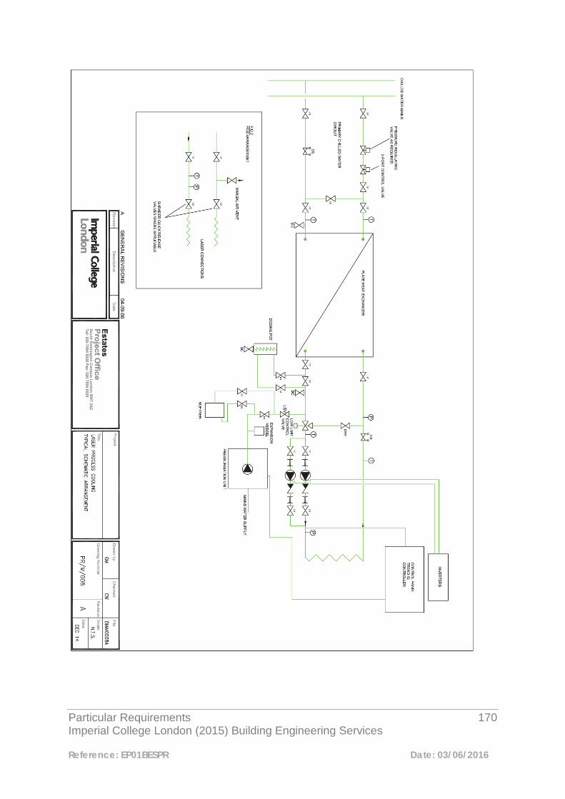
Particular Requirements 170 Imperial College London (2015) Building Engineering Services
Reference: EP01BESPR Date: 03/06/2016
Particular Requirements 171 Imperial College London (2015) Building Engineering Services
Reference: EP01BESPR Date: 03/06/2016
Appendix 13.4 Laser Equipment Data Sheet
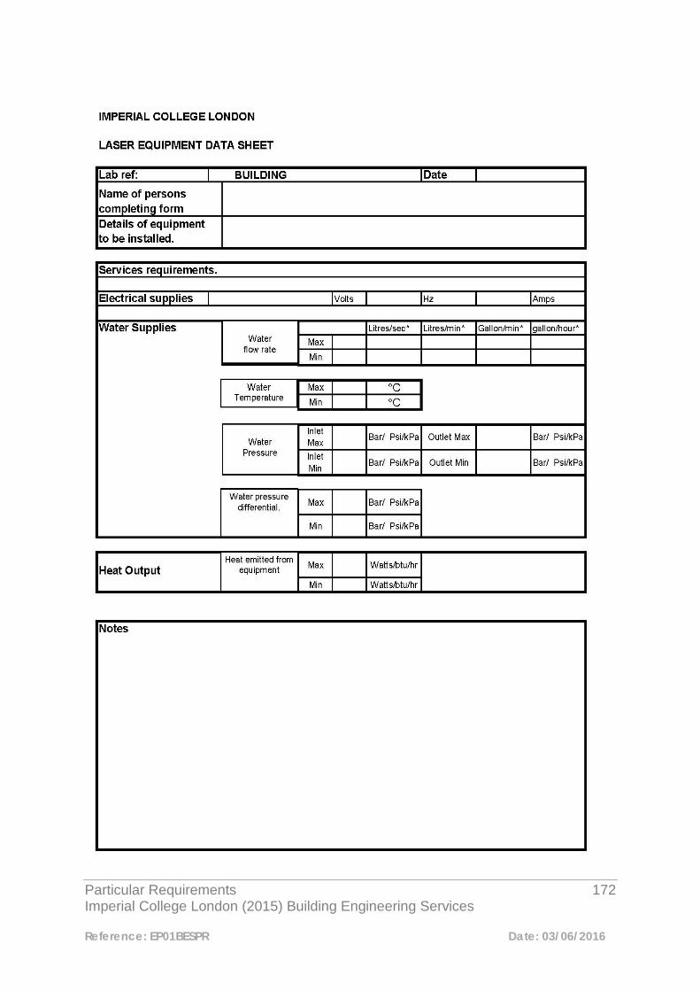
Particular Requirements 172 Imperial College London (2015) Building Engineering Services
Reference: EP01BESPR Date: 03/06/2016

Particular Requirements 173 Imperial College London (2015) Building Engineering Services
Reference: EP01BESPR Date: 03/06/2016
14 Chillers 14.1 General When specifying packaged chiller plant it shall be made clear by the designer/specifying engineer, that all necessary safety devices shall be included in the chiller package and shall protect the plant in the event of failure of the external pipe-line flow-switch. 14.2 Additional Safety Measures i) Where the chiller package includes a plate heat-exchanger the plates shall be sufficiently oversized to provide a safety margin should the chilled water leaving temperature fall dangerously low and cause freezing of the plates. ii) A differential pressure sensor shall be connected across the primary chilled water pumps. The DPS shall be connected in series with the pipe-line flow-switch and act as a secondary safety interlock and de-energise the chiller in the event of “no-flow”. (See Appendix 14.5) iii) Where a pressurised, sealed system is utilised the pressurisation unit shall be interlocked with the chiller via the BEMS. This shall de-energise the chiller in the event of a major leak occurring in the chilled water distribution system. (See Appendix 14.5). 14.3 Approved Suppliers
Particular Requirements 174 Imperial College London (2015) Building Engineering Services
Reference: EP01BESPR Date: 03/06/2016
The designer/specifier shall ensure that the chiller plant is selected from the Imperial College Approved Suppliers Components List. The final selection shall be ratified by the Engineering Manager or his representatives. 14.4 Plant Maintenance Procurement of the chiller plant package shall include for provision of a maintenance agreement with the plant manufacturer during the warranty period. Further maintenance cover will be provided under the Imperial College maintenance term agreement.
Particular Requirements 175 Imperial College London (2015) Building Engineering Services
Reference: EP01BESPR Date: 03/06/2016
Appendix 14.5 Chiller Arrangement Showing Typical Safety Devices
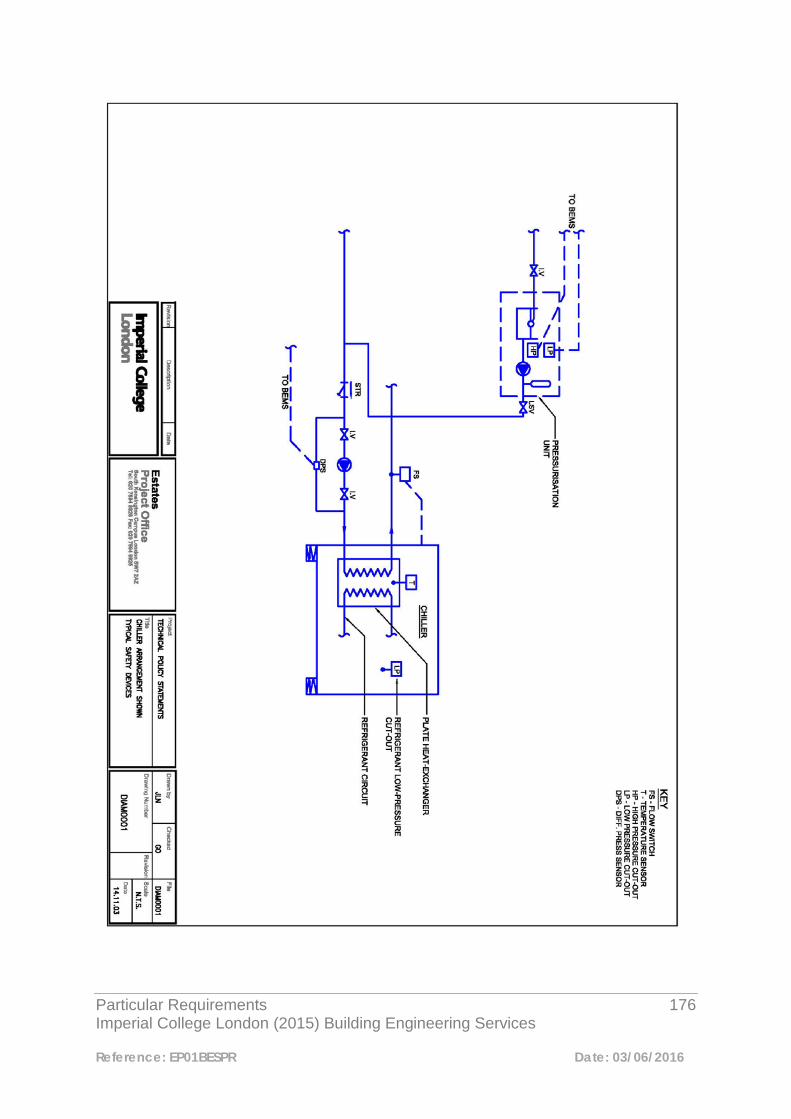
Particular Requirements 176 Imperial College London (2015) Building Engineering Services
Reference: EP01BESPR Date: 03/06/2016
Particular Requirements 177 Imperial College London (2015) Building Engineering Services
Reference: EP01BESPR Date: 03/06/2016
15 Remote Control of Ventilation Systems in Fire Condition 15.1 General The requirement for the control of ventilation plant under fire condition and the incorporation of fire alarm interface units shall be discussed and agreed with the Imperial College London Chief Fire Officer.

Particular Requirements 178 Imperial College London (2015) Building Engineering Services
Reference: EP01BESPR Date: 03/06/2016
16 Thermal Insulation and Finishes to Ductwork and Pipework 16.1 Thermal Insulating Materials All insulating materials shall comply with the requirements of BS 3958 Parts 4 and 5, BS 5422: 2009, BS 5970: 2001 and Building Regulations Part L. All insulating materials shall be Class “O” non-combustible and comply with BS 476 Part 4. All insulation shall have a smooth, homogeneous symmetrical appearance, the finished surface running true in line with the services layout. All rigid sections shall be concentric and be accurately matched for thickness, irregular or badly finished surfaces, steps or undulations in surfaces shall not be accepted.
Insulation shall fit tight to the various surfaces to be covered and all slabs and sections shall be built up close, butting edges being mitred, chamfered or shaped as necessary. Where insulation is applied to vessels or equipment it shall be neatly cut around name plates or test pressure plates, inspection covers etc. All thermostat pockets, unions, test points etc. shall be left exposed with insulation tapered neatly at either side or around the perimeter. All pipework connections, controls etc. shall project a minimum of 25mm clear of insulated surfaces. It should be noted that all ferrous pipework shall be painted with two coats of “Red-Oxide” paint prior to applying insulation.
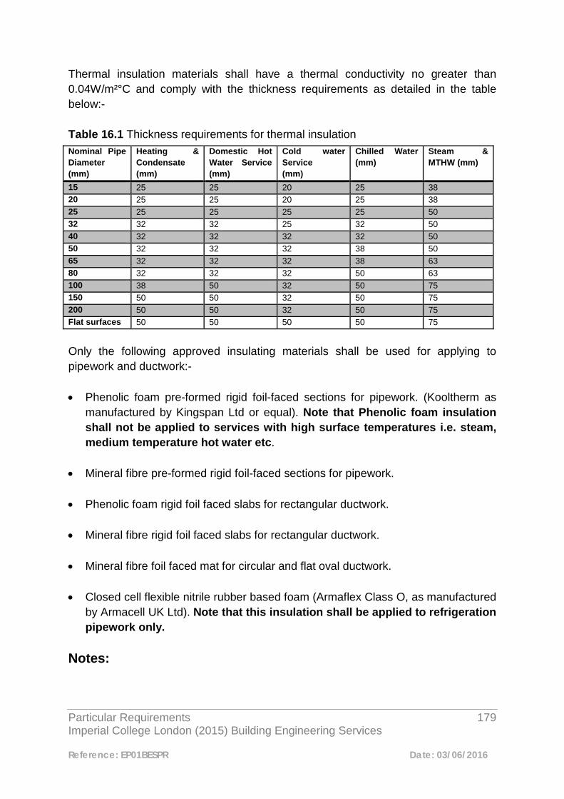
Particular Requirements 179 Imperial College London (2015) Building Engineering Services
Reference: EP01BESPR Date: 03/06/2016
Thermal insulation materials shall have a thermal conductivity no greater than 0.04W/m²°C and comply with the thickness requirements as detailed in the table below:- Table 16.1 Thickness requirements for thermal insulation Nominal Pipe Diameter (mm)
Heating & Condensate (mm)
Domestic Hot Water Service (mm)
Cold water Service (mm)
Chilled Water (mm)
Steam & MTHW (mm)
15 25 25 20 25 38 20 25 25 20 25 38 25 25 25 25 25 50 32 32 32 25 32 50 40 32 32 32 32 50 50 32 32 32 38 50 65 32 32 32 38 63 80 32 32 32 50 63 100 38 50 32 50 75 150 50 50 32 50 75 200 50 50 32 50 75 Flat surfaces 50 50 50 50 75
Only the following approved insulating materials shall be used for applying to pipework and ductwork:- • Phenolic foam pre-formed rigid foil-faced sections for pipework. (Kooltherm as
manufactured by Kingspan Ltd or equal). Note that Phenolic foam insulation shall not be applied to services with high surface temperatures i.e. steam, medium temperature hot water etc.
• Mineral fibre pre-formed rigid foil-faced sections for pipework. • Phenolic foam rigid foil faced slabs for rectangular ductwork.
• Mineral fibre rigid foil faced slabs for rectangular ductwork. • Mineral fibre foil faced mat for circular and flat oval ductwork. • Closed cell flexible nitrile rubber based foam (Armaflex Class O, as manufactured
by Armacell UK Ltd). Note that this insulation shall be applied to refrigeration pipework only.
Notes:
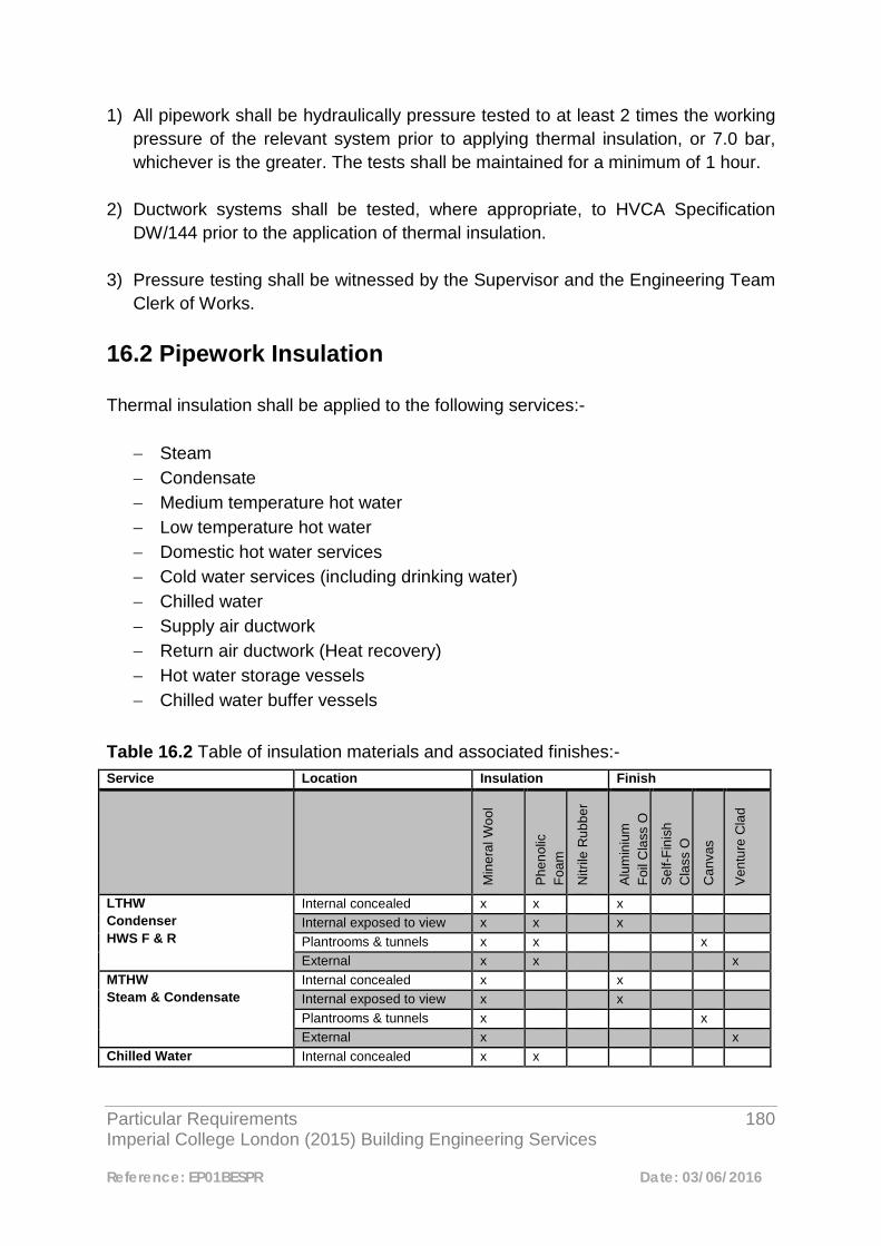
Particular Requirements 180 Imperial College London (2015) Building Engineering Services
Reference: EP01BESPR Date: 03/06/2016
1) All pipework shall be hydraulically pressure tested to at least 2 times the working pressure of the relevant system prior to applying thermal insulation, or 7.0 bar, whichever is the greater. The tests shall be maintained for a minimum of 1 hour.
2) Ductwork systems shall be tested, where appropriate, to HVCA Specification
DW/144 prior to the application of thermal insulation. 3) Pressure testing shall be witnessed by the Supervisor and the Engineering Team
Clerk of Works. 16.2 Pipework Insulation Thermal insulation shall be applied to the following services:-
− Steam − Condensate − Medium temperature hot water − Low temperature hot water − Domestic hot water services − Cold water services (including drinking water) − Chilled water − Supply air ductwork − Return air ductwork (Heat recovery) − Hot water storage vessels − Chilled water buffer vessels
Table 16.2 Table of insulation materials and associated finishes:- Service Location Insulation Finish
Min
eral
Woo
l
Phe
nolic
Fo
am
Nitr
ile R
ubbe
r
Alu
min
ium
Fo
il C
lass
O
Sel
f-Fin
ish
Cla
ss O
Can
vas
Ven
ture
Cla
d
LTHW Condenser HWS F & R
Internal concealed x x x Internal exposed to view x x x Plantrooms & tunnels x x x External x x x
MTHW Steam & Condensate
Internal concealed x x Internal exposed to view x x Plantrooms & tunnels x x External x x
Chilled Water Internal concealed x x
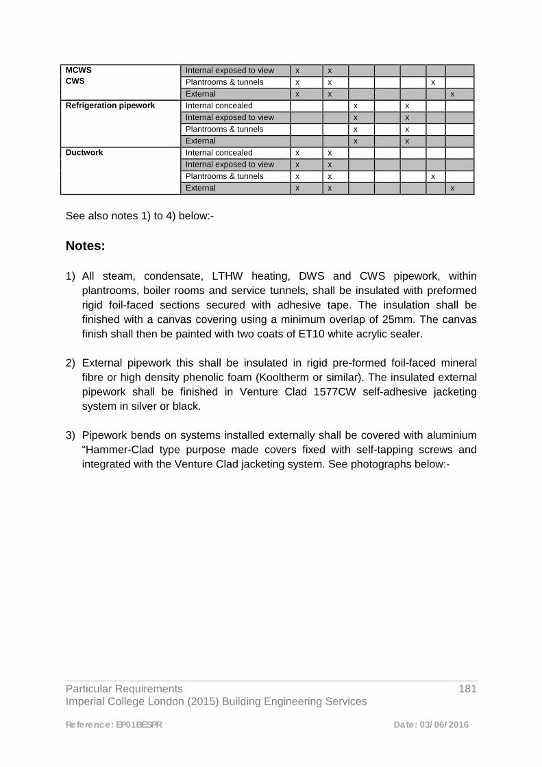
Particular Requirements 181 Imperial College London (2015) Building Engineering Services
Reference: EP01BESPR Date: 03/06/2016
MCWS CWS
Internal exposed to view x x Plantrooms & tunnels x x x External x x x
Refrigeration pipework Internal concealed x x Internal exposed to view x x Plantrooms & tunnels x x External x x
Ductwork Internal concealed x x Internal exposed to view x x Plantrooms & tunnels x x x External x x x
See also notes 1) to 4) below:- Notes: 1) All steam, condensate, LTHW heating, DWS and CWS pipework, within
plantrooms, boiler rooms and service tunnels, shall be insulated with preformed rigid foil-faced sections secured with adhesive tape. The insulation shall be finished with a canvas covering using a minimum overlap of 25mm. The canvas finish shall then be painted with two coats of ET10 white acrylic sealer.
2) External pipework this shall be insulated in rigid pre-formed foil-faced mineral
fibre or high density phenolic foam (Kooltherm or similar). The insulated external pipework shall be finished in Venture Clad 1577CW self-adhesive jacketing system in silver or black.
3) Pipework bends on systems installed externally shall be covered with aluminium
“Hammer-Clad type purpose made covers fixed with self-tapping screws and integrated with the Venture Clad jacketing system. See photographs below:-
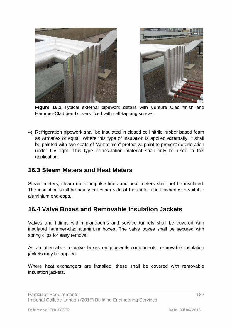
Particular Requirements 182 Imperial College London (2015) Building Engineering Services
Reference: EP01BESPR Date: 03/06/2016
Figure 16.1 Typical external pipework details with Venture Clad finish and Hammer-Clad bend covers fixed with self-tapping screws
4) Refrigeration pipework shall be insulated in closed cell nitrile rubber based foam
as Armaflex or equal. Where this type of insulation is applied externally, it shall be painted with two coats of “Armafinish” protective paint to prevent deterioration under UV light. This type of insulation material shall only be used in this application.
16.3 Steam Meters and Heat Meters Steam meters, steam meter impulse lines and heat meters shall not be insulated. The insulation shall be neatly cut either side of the meter and finished with suitable aluminium end-caps. 16.4 Valve Boxes and Removable Insulation Jackets Valves and fittings within plantrooms and service tunnels shall be covered with insulated hammer-clad aluminium boxes. The valve boxes shall be secured with spring clips for easy removal. As an alternative to valve boxes on pipework components, removable insulation jackets may be applied. Where heat exchangers are installed, these shall be covered with removable insulation jackets.
Particular Requirements 183 Imperial College London (2015) Building Engineering Services
Reference: EP01BESPR Date: 03/06/2016
16.5 Pipe Ends At the ends of insulated pipework or where any breaks occur in straight runs, i.e. between isolating valves etc, these shall be fitted with aluminium end-caps on to neatly cut insulation. 16.6 Ductwork Insulation 16.6.1 Internal Areas Supply and recirculation ductwork in internal areas shall be insulated with foil-faced slabs (rectangular) or mat (circular). For internal finishes to ductwork insulation see Table 16.2 above. 16.6.2 External Areas Supply and recirculation ductwork in external areas, shall be insulated in rigid mineral fibre or phenolic foam slabs. For external finishes to ductwork see Table 16.2 above. 16.6.3 Vapour Barriers Where vapour barriers are applied to insulation on pipework and ductwork, the integrity of the barriers should be thoroughly checked. Any damage to vapour barriers should be repaired immediately and where such barriers have been applied off site, these should be repaired to manufacturer's recommendations. Any special finishes to insulated pipework or ductwork should be applied without compromising the integrity of the vapour barrier. 16.7 Service Identification Insulated pipework shall be banded to BS 1710: 1984 to identify the service and direction of flow. Where identification banding is applied to external pipework and/or ductwork, the banding system shall incorporate UV protection.
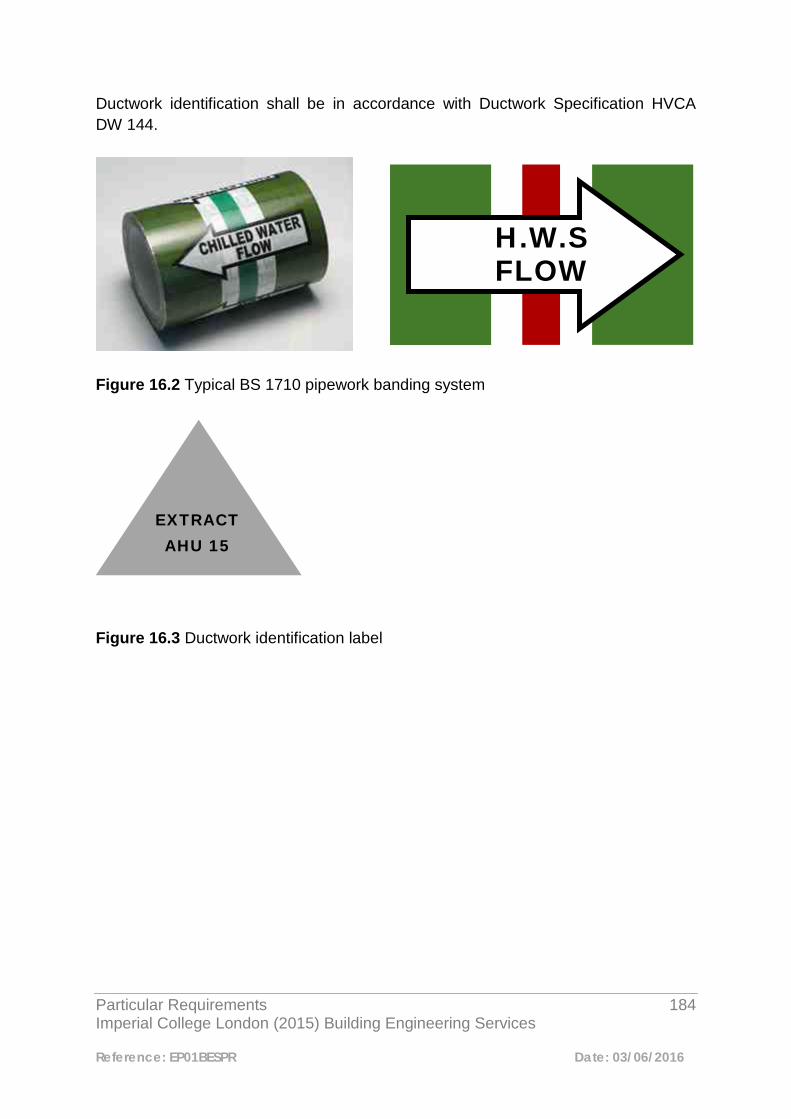
Particular Requirements 184 Imperial College London (2015) Building Engineering Services
Reference: EP01BESPR Date: 03/06/2016
Ductwork identification shall be in accordance with Ductwork Specification HVCA DW 144.
Figure 16.2 Typical BS 1710 pipework banding system Figure 16.3 Ductwork identification label
H.W.S
FLOW
EXTRACT AHU 15

Particular Requirements 185 Imperial College London (2015) Building Engineering Services
Reference: EP01BESPR Date: 03/06/2016
17
Toilet Ventilation Systems 17.1 Toilet Extract Toilet extract systems shall comprise of a direct drive twin-fan unit. The extract fan unit shall incorporate an automatic change-over controller. This shall detect duty fan failure and shall automatically switch over to the standby fan. A signal shall be given to the Building Management System via a volt-free contact to indicate that a fan failure has occurred. Vitiated air shall be drawn into a range of galvanised sheet metal ductwork and extracted at each point via ceiling mounted extract grilles. Volume control dampers shall be installed at strategic points to enable the system to be balanced and ensure the proper air flow at each point. 17.2 Toilet Supply Toilet supply/make-up air systems shall comprise of a dedicated supply air handling unit. The air handling unit shall incorporate a fan, filter, frost coil and reheat coil. (Please refer to the Air Handling Unit section of the Particular Requirements document). The toilet make-up air shall be supplied via a range of galvanised steel ductwork and air diffusers. The air shall be supplied to a toilet lobby or directly into the toilet area. Volume control dampers shall be installed at strategic points to enable the system to be balanced and ensure the proper air flow at each diffuser.
Particular Requirements 186 Imperial College London (2015) Building Engineering Services
Reference: EP01BESPR Date: 03/06/2016
Any deviation from the above shall only be considered following submission of an Exception Report. 17.3 Toilet Ventilation Rates The design ventilation rates shall be as follows:- Extract rate – 10 air changes per hour Supply rate – 8 air changes per hour 17.4 Toilet Ventilation Plant Time Control Time control of the toilet vent plant via the BEMS shall be considered at project stage and shall depend on the system usage how this is provided.

Particular Requirements 187 Imperial College London (2015) Building Engineering Services
Reference: EP01BESPR Date: 03/06/2016
18
Plant Identification 18.1 Plant and Equipment Identification Labels All new plant and equipment installed on Imperial College campuses shall be adequately labeled providing the correct identification information. All major items of plant and equipment shall be provided with “Traffolite” type labels with black characters on a white background. The labels shall be attached to plant using self-tapping screws or with adhesive. Where plant has two parts, i.e. split type direct expansion air conditioning, then both ends of the system shall be labelled. Each label shall reference the location of the other part of the system. 18.2 Equipment Asset Codes All plant and equipment shall be allocated an asset code, generated by Imperial College Estates Facilities Customer Services Centre. Where plant is being removed or amended, the asset should be identified and Imperial College Estates Facilities Customer Services Centre made aware to enable them to update their records. In most cases the asset code shall be included on the description label (See 18.4 below). Where a full description label is not required, i.e. on pipeline components etc. then the label shall refer to the asset code only.

Particular Requirements 188 Imperial College London (2015) Building Engineering Services
Reference: EP01BESPR Date: 03/06/2016
The asset tag shall be a “Traffolite” type label with white characters on a green background and shall be attached to the plant/equipment using screws, adhesive or short chain as appropriate depending on the type of equipment. 18.3 Plant and Equipment to be labeled The type of plant and equipment items to be provided with “Traffolite” type identification labels and asset tags are listed below. However, this list should not be considered to be exhaustive:-
• Chillers • Air handling units • Extract fans • Fume Extract fans • Condenser units • Boilers • Plate heat exchangers • Pumps • Humidifiers • Cold water storage tanks • Domestic hot water calorifiers • Buffer vessels • Control panels • Electrical panels • Heat meters • Steam meters
Where items of equipment are concealed in ceiling voids, such as fan coil units etc. labels should be located on the underside of units so that they are easily visible when ceiling tiles or access panels are removed. Fan coil units should be labeled so that the references i.e. FCU1, FCU2 etc. corresponds to the geographic location shown on the BEMS graphic. All pipeline valves, commissioning sets, etc. shall be labeled with disc type “Traffolite” labels using an appropriate numbering system. The valve labels should correspond to a “Valve Chart” which should be encapsulated and located in an appropriate location within the associated plant room. 18.4 Required Level of Labeling Information
Particular Requirements 189 Imperial College London (2015) Building Engineering Services
Reference: EP01BESPR Date: 03/06/2016
Plant identification labels shall provide the appropriate information to enable quick identification of the particular plant items. The required level of information is shown below:-
• Asset Code from Imperial College Estates Facilities Customer Services Centre.
• Asset description i.e. CHILLER, BOILER No 1, etc.
• Description of where plant serves e.g. LEVEL 2, BESSEMER BUILDING, ROOMS 240 - 250
• Zone being served i.e. NORTH ZONE (if applicable)Labels for plant items
such as circulating pumps etc. also need to display information such as circuit type i.e. VT or CT or CHILLED WATER with references to PRIMARY or SECONDARY heating or cooling and the particular zones being served.
Particular Requirements 190 Imperial College London (2015) Building Engineering Services
Reference: EP01BESPR Date: 03/06/2016
19
Hot and Cold Water Services 19.1 Central Systems The preferred method of raising domestic hot water is to provide a central system comprising of buffer vessels, plate heat exchangers, circulation pumps, controls etc. Shell and tube type calorifiers shall not be installed. 19.2 Minimising Risk of Legionnaires Disease Where new or extended hot and cold water systems are to be provided these shall be strictly in accordance with the recommendations set out in HSE ACoP L8 and CIBSE Technical Memorandum TM13. 19.3 Connection into Existing Hot and Cold Water Service Infrastructure Where there is a requirement to provide new or additional hot and cold water services, the College existing hot and/or cold water network may be extended. The designer/installer shall confirm to the Engineering Manager that there is sufficient capacity in the system prior to connecting to the existing infrastructure. 19.4 Secondary Circulation of Hot Water Services Where a new or extended domestic hot water service is to be provided, pumped secondary return pipework shall be incorporated.
Particular Requirements 191 Imperial College London (2015) Building Engineering Services
Reference: EP01BESPR Date: 03/06/2016
Particular care shall be taken at the system design stage to avoid dead-legs and stagnant sections in order to prevent the growth of Legionella. Only a single pump arrangement shall be acceptable on hot water service return legs to prevent the risk of Legionella growth. The use of self-regulating electric trace heating tape shall not be adopted as an alternative to a secondary circulation system without prior approval of the Engineering Manager. 19.5 Stand-Alone Point-of-Use Hot Water Heaters Where it is not practically possible to use a central system that takes its primary source of heat from the College infrastructure, local “point-of-use” type heaters shall be provided subject to approval. Where this type of system is proposed, an Engineering Exception Report shall be submitted to the Engineering Manager for approval. 19.6 Cold Water Storage Tanks All break tanks and cold water storage tanks shall be constructed of glass fibre reinforced plastic externally flanged sections. Where internally flanged tanks are required because of space restraints etc., these shall be subject to an Engineering Exception Report. Cold water storage tanks shall be complete with all the necessary access hatches, connections, bosses etc. Galvanised tanks or treated ferrous tanks shall not be installed. 19.7 Cold Water Pumping Equipment Cold water booster pumps shall be fully packaged, self-contained units comprising a number of main duty and standby pumps with automatic change-over. The booster pumps and integral control panel shall be mounted on a fabricated steel base plate/frame. The booster pump set shall provide a fault indication only, to the Building Management System.
Particular Requirements 192 Imperial College London (2015) Building Engineering Services
Reference: EP01BESPR Date: 03/06/2016
19.8 System Design All cold water and potable water systems shall be designed in accordance with BS 8558:2015 and BS EN 806: 2005. The complete design, installation, chlorinisation and commissioning procedure shall be carried out in accordance with all current codes of practice and CIBSE guidelines for domestic hot and cold water systems. 19.9 Hot and Cold Water Taps The preferred type of hot and cold water taps are the monobloc single lever type as manufactured by Grohe or equal. Taps shall be complete with a flow limiting, aerating facility to reduce water consumption. Spray type taps shall not be installed as they can create an aerosol effect increasing the risk of infection by Legionella bacteria. 19.10 Thermostatic Mixing Valves The installation of thermostatic mixing valves on hot and cold water supplies shall be restricted to wash hand basins in accessible toilets or where there are likely to be vulnerable people, i.e. young children. 19.11 Hot and Cold Water Services in Laboratories It shall be assumed that all laboratories within the College Estate are classified as high risk under Fluid Category 5 of the Water Regulations 1999. The preferred solution for back-flow prevention of water systems within laboratories shall be the provision of segregated water systems, i.e. laboratory (industrial) hot and cold water services shall be totally segregated from the domestic water services. Where segregation of services is not possible or practicable then Type DC, WRAC approved, pipe interrupters shall be installed subject to submission of an Engineering Exception Report.

Particular Requirements 193 Imperial College London (2015) Building Engineering Services
Reference: EP01BESPR Date: 03/06/2016
Where Type DC devices are installed following approval, these shall also be subject to the following provisos:- Type DC devices shall not be attached to any apparatus that would create a back pressure Type DC devices shall not be installed on outlets in Biological and Micro-biological Safety Cabinets Outlets in biosafety cabinets shall be fed via Type AA, AB or AD air gaps
Particular Requirements 194 Imperial College London (2015) Building Engineering Services
Reference: EP01BESPR Date: 03/06/2016
General
Particular Requirements 195 Imperial College London (2015) Building Engineering Services
Reference: EP01BESPR Date: 03/06/2016
1
Metering 1.1 Introduction
This Document defines the metering configurations, together with the hardware and software systems to be provided with Imperial College projects to fulfil the College’s requirements for energy, quality metering and remote monitoring facilities associated with its mechanical and electrical services and networks. Where metering is required, it will be established via the College’s Technical Advisors Group (TAG) and Engineering Review Meeting (ERM) processes. 1.2 General 1.2.1 Metered services M&E consultant draft proposals for metering design must allow for metering of the following services by end use: • Hot Water Services (HWS) • Cold Water Services • Heating (derived from LTHW, Steam, Gas, MPHW or Electricity) • Chilled Water (derived from Steam or Electricity) • Lighting • Small Power • Mechanical plant electricity usage • Sub-station transformer feed
1.2.2 Summary and general metering requirement
1.2.2.1 Summary metering diagram Figure 1.1 shows the general metering requirement:

Particular Requirements 196 Imperial College London (2015) Building Engineering Services
Reference: EP01BESPR Date: 03/06/2016
Hot water Heating
Primary LTHW MPHW Steam Gas Electric
Lighting Chilled Water Small Power
Mechanical Plant Electric
Steam Absorption Electric
Figure 1.1 Building Energy Use and Metering Requirement
1.2.2.2 Important requirements to note All proposed changes to existing metering configurations, hardware or software, will require the prior approval of the Engineering Team and Energy Team. Subject to receiving approval, all changes will be accompanied by an amended strategy (or new strategy where none currently exists) in accordance with the requirements of this document. It is the responsibility of the Principal Contractor (PC) to ensure that the overall metering design and installation complies with the project metering strategy, including coordinating mechanical and electrical metering interfaces. In addition, the mechanical / electrical contractor must supply and install metering relevant to their part of the installation in accordance with the specification and to configure this as described in this document. Meter Instrument Directive (MID) approved meters are required for billing purposes under UK national legislation (carried out by National Measurement and Regulation Office and Office of Gas and Electricity Markets). It is the responsibility of the PC to determine with the advice of Imperial Estates Energy & Engineering Teams whether MID approved meters are required. The PC is to request asset codes for each meter from the Engineering Team. Unique meter channel addresses (UPCA) will be provided by the BEMS contractor, to assist the Principal Contractor in completing the strategy drawings. Existing meters must not be isolated, temporarily or permanently disconnected and/or removed without prior written approval from both the Engineering Team and Energy Team.

Particular Requirements 197 Imperial College London (2015) Building Engineering Services
Reference: EP01BESPR Date: 03/06/2016
Existing SIPe DataPoint and DataPointTemp databases are not to be changed, adjusted or added to without written approval from the Energy Team. 1.3 Mechanical Systems For mechanical systems the following meters will be required: • Steam • Low Temperature Hot water (LTHW) • Medium Pressure Hot Water (MPHW) • Chilled Water (CHW) • Hot Water Services (HWS) • Cold Water Services (CWS) • Gas
1.3.1 Saturated Steam Each steam meter will comprise of a Spirax Gilflo ILVA pipeline mounted unit, M610 differential pressure transmitter and a M750 display unit. Installation must be as per the manufactures instructions. Each steam meter will be configured to provide a pulsed output in kg (See section 1.5.2 which describes how pulse meters are connected to SIPe). 1.3.2 LTHW, MPHW & CHW The following should be used: Endress and Hauser Promag 200 2-wire flow meter, together with E&H TR10 flow and return temperature sensors to provide signals to the RMS621. Installation to be as per the manufactures instructions. Each RMS621 Heat meter will be configured to provide a pulsed output in kWh, (see section 1.5.2 describing how pulse meters are connected to SIPe. 1.3.3 Hot Water Services (HWS) HWS will be metered from the primary energy source using:
1.3.3.1 Steam This is as per section 1.3.1.
1.3.3.2 LTHW and MPHW
Particular Requirements 198 Imperial College London (2015) Building Engineering Services
Reference: EP01BESPR Date: 03/06/2016
This is as per section 1.3.2.
1.3.3.3 Electric Socomec “A20” kWh for electric primary energy, as per section 1.4.1 1.3.4 Domestic cold water Domestic cold water meter MID R80 Class B or C will be configured to provide a pulsed output (m3) (See section 1.5.2 which describes how pulse meters are connected to SIPe) 1.3.5 Gas Meters
1.3.5.1 Utility/Billing Meters The meter(s) will be specified and installed by the gas supplier. Each gas meter must be provided with a dedicated volumetric pulse output, with EU directive Atmospheres Explosives (ATEX) approved chatter box installed to enable electrical isolation and configured to provide a pulsed output (m3) (See section 1.5.2 which describes how pulse meters are connected to SIPe).
1.3.5.2 Sub Meters
1.3.5.2.1 Diaphragm Gas Meters For applications where the minimum gas flow is low (<0.1 m³/h) a diaphragm positive displacement gas meter will be used. This type of meter has a very wide measuring range designed for low pressure and low to medium flow ranges. Each gas meter will be provided with a dedicated volumetric pulse output, all gas meters to have a chatter box installed to enable electrical isolation, each gas meter will be configured to provide a pulsed output (m3) (See section 1.5.2 which describes how pulse meters are connected to SIPe). Accuracy +/- 1.5% 1.4 Electrical Systems This section describes the following meters for electrical systems to be provided: 1.4.1 Main incoming Panels

Particular Requirements 199 Imperial College London (2015) Building Engineering Services
Reference: EP01BESPR Date: 03/06/2016
Socomec A40 meters to be supplied on all transformer incoming panels and major switchboard incoming panels where the incoming switch is either an ACB or PCCB. These meters will be equipped with RS485 communications output modules only. The data will be monitored via a SIPe/MODM/D/1VIQ. The following parameters are to be recorded in the SIPe database. 1. Total Active Energy (kWh) 2. Active Power (kW) 3. Apparent Power Total (kVa) 4. Reactive Energy Total (kVarh)
5. Amps - L1 (A) 6. Amps - L2 (A) 7. Amps - L3 (A) 8. Amps - N (A)
9. Volts - L1-N (V) 10. Volts - L2-N (V) 11. Volts - L3-N (V)
12. Total Harmonic Distortion (thd I1) for current 13. Total Harmonic Distortion (thd I2) for current 14. Total Harmonic Distortion (thd I3) for current 15. Total Harmonic Distortion (thd In) for current 16. Total Harmonic Distortion (thd V) for Voltage 1.4.2 General Electrical Circuits Socomec A20 meters with an RS485 connection to be supplied on circuits identified and agreed as requiring metering that do fall under section 1.4.1. These are to be configured to monitor kWh (active energy) meter values only, refer to section 1.5.1 which describes the method of connectivity via SIPe.
1.4.2.1 The Use of Invertors for Metering Where required, invertors for a group of pumps, fans (rated 11 kW and above) can be considered for metering; however this must be agreed with the Energy and Engineering teams prior to commencing work.
1.4.2.2 Landlord’s Supplies Where recharging of internal tenants is required, metering should be designed to allow consumption of all utilities to be established. Where external tenants will be billed MID compliant meters, type to be agreed with the Energy Team prior to installation, are to be installed.

Particular Requirements 200 Imperial College London (2015) Building Engineering Services
Reference: EP01BESPR Date: 03/06/2016
1.4.3 Alternative Meters (to the above) Where other meter types are considered, an exception report is required. 1.5 Connectivity 1.5.1 General Connectivity Energy Monitoring System integration devices must be Synapsys SIPe/MODM/D/1VIQ IF-Log. After witnessing, commissioning and handover the Energy Monitoring System will read the SIPe MySql databases (DataPoint and DataPointTemp). Each point monitored will have a unique address in the form; Device host name_Device_number E.g. sk-mec-102-sip3.ad.ic.ac.uk_Device_30 These devices connect directly to the College Ethernet network. SIPes are to be configured to record time and date information from the Trend network. (This is the reason for the 1VIQ requirement.) Each SIPe device has a web portal which allows viewing of live data energy profiles via a web browser. The Synapsys SIPe web interface must be password protected; the password must be set up in conjunction with the Energy Team. The connection procedure for mechanical and electrical systems is as follows: 1.5.2 Mechanical Systems Modbus is the required communication protocol for all meters. The Modbus network will integrate to the Energy Monitoring System via the Synapsys SIPe IF-Log device. Part no SIPe/MODM/D/1VIQ. A Modbus pulse collector will be used to integrate the meter onto the Modbus network. Where a Modbus pulse collector is used the meter multiplication factor will be added to the SIPe/MODM/D/1VIQ NOT the Modbus pulse collector. The diagram below shows a simplified illustration of the mechanical metering connection:
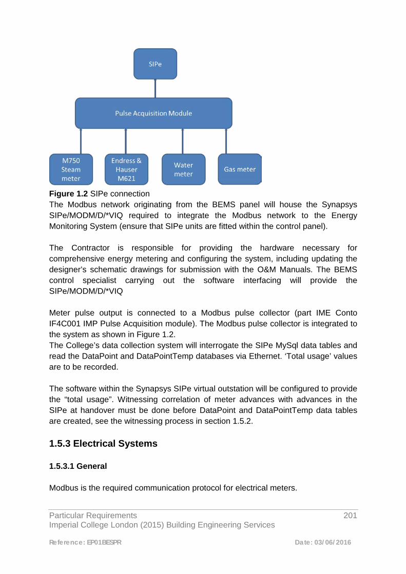
Particular Requirements 201 Imperial College London (2015) Building Engineering Services
Reference: EP01BESPR Date: 03/06/2016
Figure 1.2 SIPe connection The Modbus network originating from the BEMS panel will house the Synapsys SIPe/MODM/D/*VIQ required to integrate the Modbus network to the Energy Monitoring System (ensure that SIPe units are fitted within the control panel). The Contractor is responsible for providing the hardware necessary for comprehensive energy metering and configuring the system, including updating the designer’s schematic drawings for submission with the O&M Manuals. The BEMS control specialist carrying out the software interfacing will provide the SIPe/MODM/D/*VIQ Meter pulse output is connected to a Modbus pulse collector (part IME Conto IF4C001 IMP Pulse Acquisition module). The Modbus pulse collector is integrated to the system as shown in Figure 1.2. The College’s data collection system will interrogate the SIPe MySql data tables and read the DataPoint and DataPointTemp databases via Ethernet. ‘Total usage’ values are to be recorded. The software within the Synapsys SIPe virtual outstation will be configured to provide the “total usage”. Witnessing correlation of meter advances with advances in the SIPe at handover must be done before DataPoint and DataPointTemp data tables are created, see the witnessing process in section 1.5.2. 1.5.3 Electrical Systems 1.5.3.1 General Modbus is the required communication protocol for electrical meters.
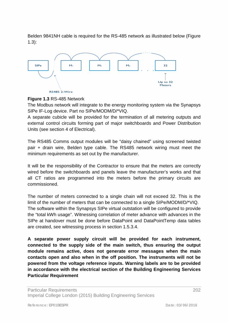
Particular Requirements 202 Imperial College London (2015) Building Engineering Services
Reference: EP01BESPR Date: 03/06/2016
Belden 9841NH cable is required for the RS-485 network as illustrated below (Figure 1.3):
SIPe M1 M2 M3 32
RS485 2-Wire
Up to 32 Meters
Figure 1.3 RS-485 Network The Modbus network will integrate to the energy monitoring system via the Synapsys SIPe IF-Log device. Part no SIPe/MODM/D/*VIQ. A separate cubicle will be provided for the termination of all metering outputs and external control circuits forming part of major switchboards and Power Distribution Units (see section 4 of Electrical). The RS485 Comms output modules will be “daisy chained” using screened twisted pair + drain wire, Belden type cable. The RS485 network wiring must meet the minimum requirements as set out by the manufacturer. It will be the responsibility of the Contractor to ensure that the meters are correctly wired before the switchboards and panels leave the manufacturer’s works and that all CT ratios are programmed into the meters before the primary circuits are commissioned. The number of meters connected to a single chain will not exceed 32. This is the limit of the number of meters that can be connected to a single SIPe/MODM/D/*VIQ. The software within the Synapsys SIPe virtual outstation will be configured to provide the “total kWh usage”. Witnessing correlation of meter advance with advances in the SIPe at handover must be done before DataPoint and DataPointTemp data tables are created, see witnessing process in section 1.5.3.4. A separate power supply circuit will be provided for each instrument, connected to the supply side of the main switch, thus ensuring the output module remains active, does not generate error messages when the main contacts open and also when in the off position. The instruments will not be powered from the voltage reference inputs. Warning labels are to be provided in accordance with the electrical section of the Building Engineering Services Particular Requirement
Particular Requirements 203 Imperial College London (2015) Building Engineering Services
Reference: EP01BESPR Date: 03/06/2016
The designer will avoid positioning meters in locations that duplicate meters at another point in the system.
1.5.3.2 Connection of inverters Where required, inverters are to be connected via SIPe measuring power in kW.
1.5.3.3 Combined Mechanical and Electrical Systems Where both mechanical and electrical systems are being provided by a Principal Contractor the design of the two systems will be integrated to make economic use of the BEMS control panels. However a separate mechanical and electrical Synapsys SIPe IF-Log device must be used for each system.
1.5.3.4 SIPe Commissioning & Witnessing Process Step A: Mechanical & Electrical Contractor to commission meters & setup
addressing as per issued schedule Step B: Controls Contractor to apply for connectivity details to the Imperial
network for the SIPe’s, (Imperial Patch Point Number and SIPe MAC address required) via contractual chain.
Step C: Controls Contractor to programme & commission SIPes & setup
Modbus slaves in the SIPe and install virtual outstation Address & LAN (refer to appendices of this section)
Step D: Controls Contractor to witness 100% to Imperial independent validator
proving correct points in data base Step E: Controls Contractor to witness 10% to Imperial BEMS engineer. Step F: Energy Engineer to confirm with BEMS contractor which points are to
be data logged in the SIPe MySql databases (post confirmation with Imperial Estates Energy Team)
Step G: Energy Team to create and verify each point from DataPoint and
DataPointTemp in the Sigma database and update metering

Particular Requirements 204 Imperial College London (2015) Building Engineering Services
Reference: EP01BESPR Date: 03/06/2016
spreadsheet. Metering spreadsheet to be sent to Energy Engineer for metering strategy update.

Particular Requirements 205 Imperial College London (2015) Building Engineering Services
Reference: EP01BESPR Date: 03/06/2016
1.6 Strategy drawings; Responsibilities & Demarcations This section describes the responsibilities and demarcation for the metering strategy drawings and is to be read in conjunction with the procedure in the Appendix 1.7 of this section. 1.6.1 Designer Before developing a metering strategy, the Project Manager will request from the Engineering Team, a copy of the current strategy. This strategy will include schematic diagrams, floor plans and spreadsheet. This will form the ‘working copy’ which the designer will amend in accordance with any proposed changes/additions. All proposed changes to the working copy will be clouded so that they can be easily identified. This applies to all drawings through all design stages, including the tender. All proposed changes will similarly be identified on the spreadsheet. Where there is no existing strategy available, the designer will develop a metering strategy, the scope of which will be agreed with the Engineering Manager and which may extend beyond the metering services defined by the project scope. Strategies will be developed fully in accordance with the requirements of this document and presented in AutoCAD .dwg format as per examples included in the appendices of this section. The draft strategies will be agreed with the College’s Engineering and Energy Teams, prior to submission as part of the normal design review process. To enable the metering proposals to be assessed in the context of the services being measured/monitored, each strategy presented to the Engineering and Energy Teams will be accompanied by the relevant services schematic. Following approval and incorporating any changes required by the Engineering and Energy Teams, the strategy is to be issued as part of the tender documentation. 1.6.2 Contractor The Principal Contractors are responsible for completing the metering schematic and strategy drawings with input from the Controls Designer. These will then be issued to the College for approval with associated asset numbers for each meter. On receipt of approval, the completed metering strategy will be passed to the appointed Controls Contractor for the addition of the unique meter channel address (UPCA).

Particular Requirements 206 Imperial College London (2015) Building Engineering Services
Reference: EP01BESPR Date: 03/06/2016
UPCA references will be provided by the Controls Contractor in the format shown in the example below to assist the contractor in completing the strategy drawings. Hostname_Device_number E.g. sk-mec-102-sip3.ad.ic.ac.uk_Device_30 The Controls Contractor will add these to the Strategy, together with the meter serial numbers and issue to the Energy Engineer, Engineering Team, for comments /approval. At practical completion, the metering strategy drawings (plans and schematics) together with the spreadsheet will be issued as part of the O&M documentation, and will be used by the Engineering Team to update the master set. All amendments/additions to the tender drawings and schedules will be carried out using a different colour or some other notation so that changes can be easily identified. Appendix 1.7 Approvals Procedure Step 1: Project Manager (PM) to request existing building metering strategy
from Engineering Team Energy Engineer Step 2: PM issues existing strategy to M&E designer. Step 3: M&E Designer creates a “working copy” by amending the existing
strategy in accordance with proposed works. Where no metering strategy exists the M&E Designer creates a new strategy in discussion with the Engineering Manager / Energy Engineer
Step 4: M&E Designers agrees strategy with the Colleges’ Energy and
Engineering Teams. Energy Engineer assesses the impact on algorithms
Step 5: Metering strategy issued as part of tender documentation Step 6: Meters are installed as per contract requirements. Step 7: Controls Contractor to set up meters with addresses, update metering
strategy and issue to PM. Step 8: PM requests meter asset number from Engineering Team Step 9: Engineering Team issue asset number and issue back to PM.

Particular Requirements 207 Imperial College London (2015) Building Engineering Services
Reference: EP01BESPR Date: 03/06/2016
Step 10: Controls Contractor to setup Modbus slaves in the SIPe and allocate
virtual outstation points (this includes all points even via a pulse counter)
Step 11: Controls Contractor to request address details once patch point & Mac
details are known via contract chain Step 12: Controls Contractor to install address details when issued Step 13: Controls Contractor to update metering strategy, College SIP register
with UCMA, meter details and forward to PM. PM to forward this information to the Energy Engineer for comment
Step 14: Controls Contractor to commission meter reading. Step 15: Imperial independent validator to witness and signoff 100% of meters
ensuring meter advances are reflected in the corresponding Trend points in the SIPe
Step 16: Engineering team witness and signoff 10% of meters ensuring meter
advances are reflected in the corresponding Trend points in the SIPe Step 17: Controls Contractor to issue to PM final excel spread sheet with all
data logged in the SIPe MySql databases Step 18: Energy Team to create and verify each point from DataPoint and
DataPointTemp in to the Sigma test machine database Step 19: Energy Engineer updates meter records, checks and updates
algorithms
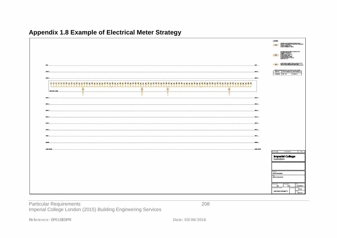
Particular Requirements 208 Imperial College London (2015) Building Engineering Services
Reference: EP01BESPR Date: 03/06/2016
Appendix 1.8 Example of Electrical Meter Strategy
Particular Requirements 209 Imperial College London (2015) Building Engineering Services
Reference: EP01BESPR Date: 03/06/2016
Appendix 1.9 Example of Mechanical Meter Strategy
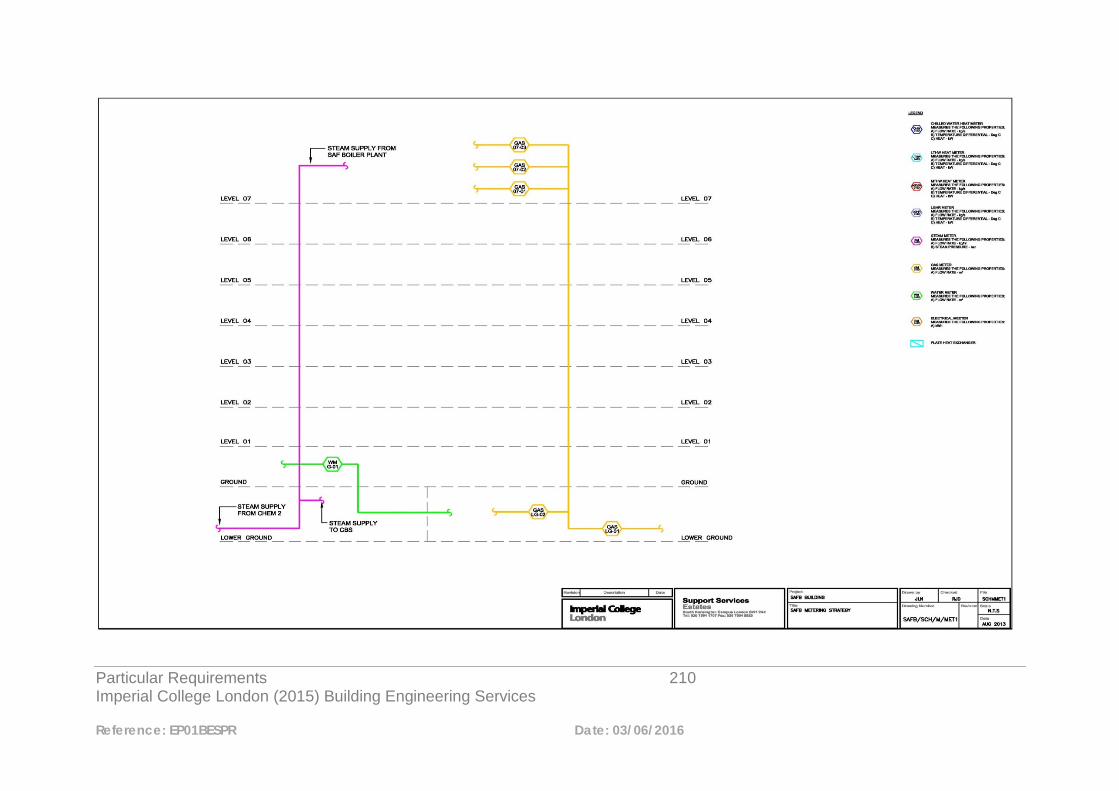
Particular Requirements 210 Imperial College London (2015) Building Engineering Services
Reference: EP01BESPR Date: 03/06/2016
Particular Requirements 211 Imperial College London (2015) Building Engineering Services
Reference: EP01BESPR Date: 03/06/2016
Appendix 1.10 Metering Schedule
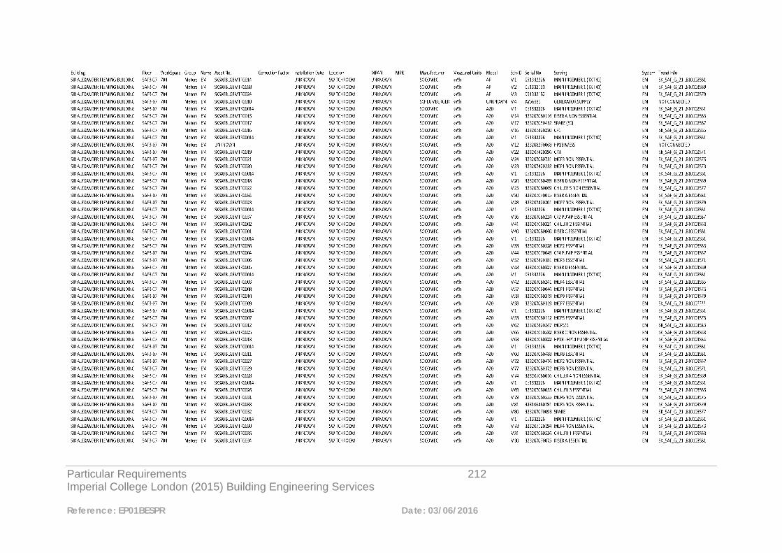
Particular Requirements 212 Imperial College London (2015) Building Engineering Services
Reference: EP01BESPR Date: 03/06/2016
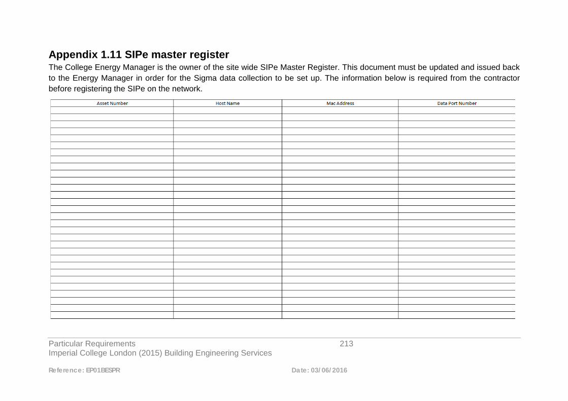
Particular Requirements 213 Imperial College London (2015) Building Engineering Services
Reference: EP01BESPR Date: 03/06/2016
Appendix 1.11 SIPe master register The College Energy Manager is the owner of the site wide SIPe Master Register. This document must be updated and issued back to the Energy Manager in order for the Sigma data collection to be set up. The information below is required from the contractor before registering the SIPe on the network.
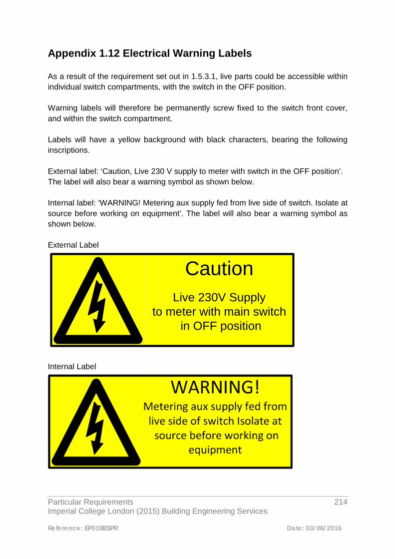
Particular Requirements 214 Imperial College London (2015) Building Engineering Services
Reference: EP01BESPR Date: 03/06/2016
Appendix 1.12 Electrical Warning Labels As a result of the requirement set out in 1.5.3.1, live parts could be accessible within individual switch compartments, with the switch in the OFF position. Warning labels will therefore be permanently screw fixed to the switch front cover, and within the switch compartment. Labels will have a yellow background with black characters, bearing the following inscriptions. External label: ‘Caution, Live 230 V supply to meter with switch in the OFF position’. The label will also bear a warning symbol as shown below. Internal label: ‘WARNING! Metering aux supply fed from live side of switch. Isolate at source before working on equipment’. The label will also bear a warning symbol as shown below. External Label
Internal Label
CautionLive 230V Supply
to meter with main switch in OFF position
Particular Requirements 215 Imperial College London (2015) Building Engineering Services
Reference: EP01BESPR Date: 03/06/2016
2 Equality Act 2010 Electronic Systems 2.1 Access and Egress - Access Control and Automatic Doors 2.1.1 Introduction Where access control is installed, the following, as per the BSIA (British Standard Industry Association) “A Guide to Assist in Compliance with the Disability Discrimination Act (now Equality Act 2010)” should be considered. 2.1.2 General Access doors should be so designed as to permit operation by one person in a single motion with little effort. Power-operated doors are preferred for people with disabilities. 2.1.3 Door types 1. Automatic doors: - can be of the sliding or swinging type. In general sliding doors
are preferable to swinging doors. • Automatic doors are useful when traffic is heavy. • Automatic doors should have an adequate opening interval. • Guard-rails can be installed near double swinging doors to indicate a door
opening area and to prevent people from being hit by the door. 2. Revolving doors: - not suitable for use by disabled people or people with prams
unless fitted with built in Sliding Door Function.
Particular Requirements 216 Imperial College London (2015) Building Engineering Services
Reference: EP01BESPR Date: 03/06/2016
• Wherever there are revolving doors, an adjacent accessible swinging or sliding door should be provided.
• Auxiliary gates should be provided next to turnstiles. 3. Pivoted doors: - should swing away from the direction of travel wherever
possible. • Pivoted doors in series are considered as vestibules. 4. Sliding and folding doors: - manual sliding and folding doors are recommended
for narrow spaces not heavily used by the public. 2.1.4 Access Control Readers Readers on entrance doors should be mounted at a comfortable height between 0.90m and 1.00m from the floor.
2.1.4.1 Automatic Doors Hardware Automatic doors can be activated by: 1. Push buttons located at a comfortable height between 0.90m and 1.20m; 2. Activating mats which can also serve as a location cue. 3. Access Control Readers: readers on entrance doors should be mounted at a
comfortable height between 0.90m and 1.00m from the floor. 4. Remote control. 5. Movement Detection Devices. 2.1.5 Turnstiles Turnstiles are often used in the reception areas of a building or its perimeter. These are used to provide a higher level of security than a door, by checking each individual is authorised and denying access to those who are not. Here is a summary of the types of turnstiles available along with a brief introduction to their operation and suitability. 2.1.6 Optical Turnstiles
2.1.6.1 Typical Application Well managed reception areas where aesthetics and speed of throughput are the key issues.

Particular Requirements 217 Imperial College London (2015) Building Engineering Services
Reference: EP01BESPR Date: 03/06/2016
2.1.6.2 Operation Optical Turnstiles are designed to replace traditional fixed arm turnstiles used to control building access. They utilize infrared beams between pedestals to remove the need for the physical barrier. Optical Turnstiles provide a similar level of security as a traditional half height turnstile, yet the open appearance created by an optical turnstile ensures acceptance in most office environments where the overall design is of paramount importance to the aesthetics of the building. Optical Turnstiles automatically monitor the passage of every individual entering and leaving a building. Security staffs are therefore only required to deal with exceptions such as unauthorised users or visitors without a valid pass. Lane widths can be adjusted to accommodate wheelchairs without the need for a separate passgate; therefore all system users utilise the same technology with no discrimination. Most models also feature audible and visual feedback. 2.1.7 Half Height Fixed Arm Turnstiles
2.1.7.1 Typical Application Constantly manned reception areas where appearance is not the highest requirement.
2.1.7.2 Operation Fixed arm turnstiles are available in a wide variety of formats and can be made up of three stainless steel tubes making a tripod mechanism or glass panels to make a more discreet finish. A half height turnstile is not compliant in its own right. This type of turnstile may be compliant if a ‘reasonable adjustment’ is made i.e. a separate passgate is installed. Although not stated explicitly in the Act it may be argued that a passgate is discriminatory because it forces disabled users to use a different kind of technology and to be supervised or even aided – often a guard needs to be summoned to open the gate (rather than the person using a card like other people) so they can make sure only one person goes through when the gate is open. Normally passgates and turnstiles do not feature audible and visual feedback so this should also be considered. 2.1.8 Speedgates
2.1.9.1 Typical Application Reception areas where aesthetics, speed of throughput and security are key issues.
Particular Requirements 218 Imperial College London (2015) Building Engineering Services
Reference: EP01BESPR Date: 03/06/2016
2.1.9.2 Operation Speedgates combine features of optical turnstiles and physical turnstiles. A lane is monitored by infrared beams and a physical barrier is used to physically deter entrants. They are available in normally open or normally closed models and combine the open look and speed of throughput of optical turnstiles with the deterrent factor of traditional turnstiles. This combination of benefits makes the speedgate an ideal choice for the corporate office lobby. Most manufacturers make compliant versions. However, for some units, this can mean a significantly wider pedestal is needed to accommodate the longer barriers (which will affect the aesthetics and available space). Most models also feature audible and visual feedback. 2.1.9 Full Height Turnstiles
2.1.9.1 Typical Application Full height turnstiles are normally used on external perimeters in unguarded areas or higher security sites e.g. football stadiums etc. They are a good option for commercial and industrial facilities where security and guarding costs are more important than appearance.
2.1.9.2 Operation Full height turnstiles are designed to stop people jumping over the units hence they can be unmanned. In some designs it is possible to get 2 people in a section at one time. The barriers are normally finished in steel but some units use clear perspex to give an improved aesthetic appearance. Full height turnstiles are generally not compliant. They cannot accommodate wheelchairs. Alternative measures need to be provided. Additionally turnstiles do not normally feature audible and visual feedback so this should be considered as well. 2.1.10 Tailgate Detection Devices
2.1.10.1 Typical Application Primarily used on the main entrance for small sites and back doors and key doors within larger sites, e.g. cash rooms, computer suites etc.
Particular Requirements 219 Imperial College London (2015) Building Engineering Services
Reference: EP01BESPR Date: 03/06/2016
2.1.10.2 Operation Tailgate Detection devices uniquely answer the problem of tailgating at access controlled doors by creating an infrared field across the door opening to monitor the passage of every individual entering and leaving through that door. In the event of an unauthorised person following an authorised user through a door after it has been opened the system can provide local and remote indications to alert the individual concerned and security. Additionally the system can lock doors and trigger cameras to monitor illegal transactions and ensure events are recorded for later analysis. This ensures only one person gains access through a secured door for each valid card transaction thereby providing improved security at any access controlled door. Detectors can operate at up to 2.5 metres apart (subject to door widths) to accommodate wheelchairs; therefore all system users utilise the same technology with minimal supervision and no discrimination. They can be used across wide corridors and double doors; however, people should be restricted to passing through single-file i.e. one door leaf should be secured for normal application. Most models also feature some form of audible and visual feedback. 2.1.11 College Preferences
2.1.11.1 Access Control Reader Types • Contactless Proximity Card Readers with read range of 2-5cm. (Refer to Building
Engineering Services Particular Requirements document, General, Section 2.)
2.1.11.2 Door Types • When choosing Automatic door openers they have to be fit for purpose
(preferably to be manually operated when used by able bodied persons). • Revolving Doors with built in Sliding Door or additional Swinging or Sliding Door. • Half Height Fixed Arm Turnstiles with additional Swinging DDA Passgate for
Internal Areas. • Full Height Turnstiles with additional Swinging or Sliding Passdoor for External
Areas.
2.2 Fire Alarms 2.2.1 General

Particular Requirements 220 Imperial College London (2015) Building Engineering Services
Reference: EP01BESPR Date: 03/06/2016
The following information with regards to Fire alarm alert signals is from BS5588-8: Code of practice for means of escape for disabled people. “Perhaps the most commonly recognised difficulty in this respect is that experienced by those with impaired hearing. However, it should be stressed that impairment of hearing in no way means that a person is completely insensitive to sound. Many people with severe impairment have sufficiently clear perception of some types of conventional audible alarm signals to require no special provision. Where this is not the case, in most situations there will be people about who can alert those with impaired hearing to the need for evacuation and it will be reasonable to rely upon these others to provide the necessary warning. In certain situations, such as a generally noisy area where audible alarms may not be heard, alternative types of alarm signal may be necessary, for example visual alarms, paging systems, vibrating devices or sound signals within carefully selected frequency bands. The type of alarm chosen should be appropriate for the activities being carried out in the area being considered”. Further Guidance is given in BS 5839-1: Code of practice for system design, installation, commissioning and maintenance. “Impairment of hearing does not mean that a person is completely insensitive to sound. Many people with severe impairment have sufficiently clear perception of some types of conventional audible alarm signals to require no special provision for warning of fire. There will be, in some situations, other people present who can alert those with impaired hearing to the need for evacuation, and in this case it might be necessary to put procedures in place that rely upon others to provide the necessary warning”. “However, in circumstances, such as buildings with a significant number of people with impaired hearing, buildings in which one or more persons with impaired hearing work in relative isolation, and buildings in which one or more persons with impaired hearing tend to move around the building to a significant extent, additional means of giving warning to people with impaired hearing might be appropriate. If the occupants in question tend to be located for a large proportion of their time within a limited area of the building, visual alarm signals might be appropriate in that area (and associated toilets). If they sleep in the building, tactile devices, with or without associated visual alarm devices, might need to be considered. These devices, which may, for example, be placed under pillows or mattresses, may be wired into fire alarm device circuits or be triggered by radio signals”. “Alarm devices for the hearing impaired may be fixed, movable or portable. Fixed equipment is equipment fastened to a support or otherwise secured in a specific location, or equipment not provided with a carrying handle and having such a mass

Particular Requirements 221 Imperial College London (2015) Building Engineering Services
Reference: EP01BESPR Date: 03/06/2016
that it cannot easily be moved (e.g. a fire alarm system control panel screwed to the wall)”. “Moveable equipment is equipment which is not fixed equipment and which is not normally in operation while the location is changed (e.g. a local unit or controller which is placed on a table top and operates a vibrating pad in a bed)”. 2.2.2 Emergency Messaging Systems Portable equipment is equipment designed to be in operation while being carried. (e.g. radio pager! or other system using radio communication"). For the purposes of this clause, portable alarm devices are: • Intended for carrying by the hearing impaired • Capable of giving visual and/or tactile signals • Normally radio controlled but other methods are not excluded • Normally require control equipment for transmission of signals to the portable
devices, interfaced to the fire detection and alarm control equipment. Note No British Standard specifications for alarm devices for the hearing impaired are available at present in the UK. Nevertheless, wherever possible, the recommendations of this clause should be followed and any variations ought to be subject to a risk assessment to ensure that no hearing impaired person is exposed to undue risk. 2.2.3 College Preferences
2.2.3.1 Fire Alarm System Communication Systems • Sounders and Beacons to be fitted in W.Cs and Meeting/Seminar Rooms. • DeafWatch systems are currently installed in all Buildings at the South
Kensington Campus, and a number of other Buildings at the outline Campuses, vibrating pagers are available from the Fire Office.
2.3 Refuge Areas 2.3.1 Emergency Voice Communication Systems Where Refuge Areas are required, as per Part M Building Regulations “The need for Management arrangements to provide assisted escape” the following from BS
Particular Requirements 222 Imperial College London (2015) Building Engineering Services
Reference: EP01BESPR Date: 03/06/2016
5588-8: Code of practice for means of escape for disabled people should be adhered to: “There is an essential requirement for independent communication between the occupants and evacuation management personnel” with guidelines set in BS 5588-12: Managing fire safety as below. 1) The disabled people in each refuge should be assured that their presence there is known to the building Management; 2) In order to avoid anxiety and confusion, the disabled people in each refuge should be kept informed of the situation and told about the action that building management is taking in order to affect their safe evacuation. To address these issues there has to be a system of two-way communication between those temporarily waiting in each refuge, and building management members who are organizing the evacuation of the building. The two-way communication system needs to be such that it is readily operated by, and comprehensible to disabled people. To comply with the above, the BS 5839:9 Code of practice for the design, installation, commissioning and maintenance of emergency voice communication systems; should be adhered too. 2.4 Signage 2.1 General The following recommendations are applicable. 1. Refuges and evacuation lifts should be clearly identified by appropriate fire safety
signs. 2. Where a refuge is in a lobby or stairway, it is essential that the sign is
accompanied by a blue mandatory sign worded “Refuge keep clear”. 2.4.2 College Preferences 2.4.2.1 Refuge Areas Two systems are currently in operation; please consult with the Fire and Security Engineer for the most appropriate system to use: • Commend Refuge System
Particular Requirements 223 Imperial College London (2015) Building Engineering Services
Reference: EP01BESPR Date: 03/06/2016
• Baldwin Boxall “Vigil CommuniCare Advance” Refuge System with hands free 2 way communication, activated on Fire Alarm activation. This is also to be fitted with an override.
• Main Control Panel to be located adjacent to the Building Fire Alarm Panel. 2.5 Sanitary Accommodation
2.5.1 Emergency Assistance Alarm
As per Part M Building regulations, any emergency assistance alarm system has to incorporate; 1. Visual and audible indicators to confirm that an emergency call has been received; 2. A reset control reachable from a wheelchair and the WC, or from the wheelchair and the shower/changing seat; 3. A signal that is distinguishable visually and audibly from the fire alarm. 2.5.2 Fire Alarms As per Part M Building regulations, any fire alarm emits a visual and audible signal to warn occupants with hard of hearing or visual impairments. 2.5.3 College Preferences 2.5.3.1 Sanitary Accommodation Alarms
• Commend Assistance Alarm to connect to main system. • Fire Alarm Warning to be of Sounder and Beacon Type.