building energy research grant (berg) program · building energy research grant (berg) program berg...
TRANSCRIPT

BUILDING ENERGY RESEARCH GRANT (BERG) PROGRAM
BERG FINAL REPORT
Indirect Evaporative Heat Recovery Ventilator Heat Exchanger (IEHRV-HX)
BERG AWARDEE Davis Energy Group, Inc.
123 C Street, Davis, CA 95616 Phone: (530) 753-1100
Email: [email protected]
AUTHORS
Eric Lee, Principal Investigator
Grant #: 55183A/07-02B
Grant Funding: $199,916
Term: December 10, 2007 – June 15, 2009
PIER Subject Area: Building Efficiency

Legal Notice
This report was prepared as a result of work sponsored by the California Energy Commission (Commission). It does not necessarily represent the views of the Commission, its employees, or the State of California. The Commission, the State of California, its employees, contractors, and subcontractors make no warranty, express or implied, and assume no legal liability for the information in this report; nor does any party represent that the use of this information will not infringe upon privately owned rights. This report has not been approved or disapproved by the Commission nor has the Commission passed upon the accuracy or adequacy of the information in this report. Inquires related to this final report should be directed to the Awardee (see contact information on cover page) or the BERG Program Administrator at (619) 594-1049 or email [email protected].

Acknowledgements
The Principle Investigator would like to thank the following firms and persons for their participation in the Indirect Evaporative Heat Recovery Ventilator Heat Exchanger project:
• California Energy Commission • Chris Scruton
• Davis Energy Group (Davis, California)
• Mark Berman • Steve Brennan • Stephan Barson • Josh McNeil • Charlie Persson
• Pride Polymers (Yakima, Washington)
• Joe O’Malley
• Irwin Research and Development (Yakima, Washington) • Greg Barstad
• Design Services (Yakima, Washington)
• Greg Anderson

Table of Contents Legal Notice ...............................................................................................................................ii
Acknowledgements....................................................................................................................iii
Table of Contents.......................................................................................................................iv
List of Figures............................................................................................................................iv
Abstract .......................................................................................................................................i
Executive Summary....................................................................................................................1
Introduction ................................................................................................................................5
Project Objectives .......................................................................................................................6
Project Approach ........................................................................................................................7
Project Outcomes......................................................................................................................27
Conclusions ..............................................................................................................................37
Recommendations.....................................................................................................................39
Public Benefits to California .....................................................................................................40
Glossary....................................................................................................................................43
Development Status Questionnaire............................................................................................44
List of Figures Figure 1: IEHRV Concept...........................................................................................................5
Figure 2 - Test Setup Schematic..................................................................................................8
Figure 3 - Test Setup...................................................................................................................9
Figure 4 – Instrument Panel ......................................................................................................11
Figure 5 – Instrument Panel ......................................................................................................11
Figure 6 – Instrumentation in Dry Passages...............................................................................11
Figure 7 – VCEC/IEHRV Tool Design .....................................................................................13
Figure 8 – VCEC/IEHRV Thermoforming Tool (Top Half) ......................................................14
Figure 9 – VCEC/IEHRV Thermoforming Tool (Bottom Half).................................................15
Figure 10 – VCEC/IEHRV Thermoforming Tool (Bottom Half) ...............................................15
Figure 11 – Heat Seal Assembly Station ...................................................................................16
Figure 12 – Heat seal assembly station. .....................................................................................16

Figure 13 – Flocked, Thermoformed Material in Heat Sealing Station ......................................17
Figure 14 – Heat-Sealed Heat Exchanger Plates. .......................................................................17
Figure 18 – IEHRV Tool Package for C-C Plates......................................................................21
Figure 19 – IEHRV Tool Package for C-C Plates......................................................................22
Figure 15 – IEHRV Casing Assembly.......................................................................................23
Figure 16 – IEHRV Casing (Dry End) ......................................................................................24
Figure 17 – IEHRV Casing (Wet End) ......................................................................................25
Figure 20 - VCEC Dry Passage Pressure Drop v. Flow Rate .....................................................28
Figure 21 - VCEC Wet Passage Pressure Drop v. Flow Rate (flocked module) .........................29
Figure 22 - VCEC Dry Passage CFD Pressure Distribution.......................................................30
Figure 23 - VCEC Dry Passage CFD Velocity Magnitude Trace...............................................30
Figure 24 - VCEC Dry Passage CFD Velocity Magnitude Distribution .....................................31
Figure 25: Task 3 VCEC and IEHRV-HX Prototype.................................................................31
Figure 26 – CFD Results for New Wet Side IEHRV Design – Pressure Distribution.................34
Figure 27 – CFD Results for Wet Side IEHRV Design - Velocity Magnitude Trace..................35
Figure 28 – CFD Results for Wet Side IEHRV Design - Velocity Magnitude Distribution ........35
Figure 29 – Cumulative GHG Savings ......................................................................................41
List of Tables Table 1 - VCEC Test Instrumentation .......................................................................................10
Table 2 – Task 4 Test Conditions ..............................................................................................18
Table 3 – Task 4 Data Points.....................................................................................................19
Table 4 - Flow Rates.................................................................................................................26
Table 5 - Indirect Cooling Test Results .....................................................................................27
Table 6 – Task 4 Test Results....................................................................................................33
Table 7 - Prototype Pricing .......................................................................................................36
Table 8 - Volume Production Pricing ........................................................................................37
Table 9 – Public Benefits to California......................................................................................41

i
Abstract The overall goal of this project was to develop an innovative, low-cost evaporative heat exchanger for use in heating, ventilation and air-conditioning equipment such as the Indirect Evaporative Heat Recovery Ventilator. The Indirect Evaporative Heat Recovery Ventilator Heat Exchanger is produced with high-speed inline thermoforming equipment from flocked polymer film. The material is then fan-folded and heat sealed to create robust separation between wet and dry passages. After installation into a corrugated plastic casing, the heat exchanger modules are ready for use in HVAC equipment. Several indirect evaporative heat exchangers are currently available, but high cost, high pressure drop, and/or low performance have limited penetration into the commercial packaged air-conditioner market. All others use the cross-flow configuration, which limits packaging flexibility and results in large cabinets. The project team succeeded in all key metrics by achieving 70 percent indirect evaporative effectiveness and less than 1.0 inWC pressure drop in heat exchanger prototypes. Tooling to produce the Indirect Evaporative Heat Recovery Ventilator Heat Exchanger and its sister product, the Vertical Counterflow Evaporative Cooler, are at pilot production levels, with only minor refinements needed for full-production scale. Project test results demonstrated that the Indirect Evaporative Heat Recovery Ventilator Heat Exchanger technology eliminates the energy penalty of ventilation air by consistently generating supply air that was cooler than the return air. The researchers will seek additional research, development and demonstration funding to continue development of the Indirect Evaporative Heat Recovery Ventilator and its heat exchanger. Key Words: indirect evaporative, plastic plate-type air-to-air heat exchanger, vapor compression, heating, ventilation and air conditioning, rooftop packaged unit.

1
Executive Summary
Introduction The overall goal of this project was to develop an innovative, low-cost evaporative heat exchanger for use in heating, ventilation and air conditioning equipment such as the Indirect Evaporative Heat Recovery Ventilator. The Evaporative Heat Recovery Ventilator Heat Exchanger is produced with high-speed inline thermoforming equipment from flocked polymer film. The material is then fan-folded and transported to a sealing station, where adjacent plates are heat sealed to create robust separation between wet and dry passages. After installation into a corrugated plastic casing, the heat exchanger modules are ready for use in heating, ventilation and air conditioning equipment. Modules prices will be competitive from pilot production stage forward, thanks to low material costs, low labor content, and minimal machine time. Tooling to produce the Evaporative Heat Recovery Ventilator Heat Exchanger and its sister product, the Vertical Counterflow Evaporative Cooler, are at pilot production levels, with only minor refinements needed for full-production scale. Successful development and commercialization would provide a long needed alternative to electricity demand-intensive conventional heating, ventilation and air conditioning equipment. Several indirect evaporative heat exchangers are currently available, but high cost, high pressure drop, and/or low performance have limited penetration into the commercial heating, ventilation and air conditioning market. All others use the cross-flow configuration, which limits packaging flexibility and results in large cabinets. In this project, the team tested a sister heat exchanger but was not able to test an Evaporative Heat Recovery Ventilator Heat Exchanger prototype due to a truncated performance period. However, the team was able to complete the design of the Evaporative Heat Recovery Ventilator Heat Exchanger plates using computational fluid dynamics, which was calibrated with the test data from the sister product. At the conclusion of the Evaporative Heat Recovery Ventilator Heat Exchanger project, the thermoforming tooling was completed and prototypes fabricated. The research team is seeking additional R&D funding to test the Evaporative Heat Recovery Ventilator Heat Exchanger prototypes and develop the balance of the Evaporative Heat Recovery Ventilator unit.
Project Objectives
• Demonstrate indirect evaporative cooling exceeding 50% of the outdoor wet-bulb depression.
• Produce heat exchange plate design with computational fluid dynamics simulation results with full-flow pressure drop of less than 2.0 inches of Water Column, and generate 2 dimensional drawing files of final heat exchanger plate design for thermoform tooling.
• Fabricate heat exchanger prototype number 1. • Demonstrate indirect evaporative cooling exceeding 60% of the outdoor wet-bulb
depression and full-flow pressure drop less than 1.75 inches of Water Column. • Revise heat exchange plate design with computational fluid dynamics simulation results
with full-flow pressure drop of less than 1.75 inches of Water Column, and generate 2D drawing files of final heat exchanger plate design for thermoform tooling.

2
• Demonstrate indirect evaporative cooling exceeding 70% of the outdoor wet-bulb depression and full-flow pressure drop less than 1.5 inches of Water Column.
• Analyze and produce a final report, including wholesale cost model, followed in due
course by submission of an American Society of Heating, Refrigeration and Air Conditioning Engineers paper.
Project Outcomes
• Two rounds of testing showed indirect evaporative effectiveness in excess of 70%, surpassing project objectives #1 (50%) and #4 (60%).
• Testing in Task 4 showed pressure drop less than 1.0 inch of Water Column for all test conditions, surpassing objectives #2 (2.0 inches of Water Column) and #4 (1.75 inches of Water Column).
• Near-production-ready Evaporative Heat Recovery Ventilator Heat Exchanger thermoforming tooling and heat-sealing equipment
• Production-ready corrugated plastic Evaporative Heat Recovery Ventilator Heat Exchanger module casing design
• Sustainable Evaporative Heat Recovery Ventilator Heat Exchanger economics Because of a truncated performance period (due to external factors at the Energy Commission), the team was not able to test the final Evaporative Heat Recovery Ventilator Heat Exchanger modules. However, the research team is confident of securing public R&D funding to test the modules as well as to develop the balance of the Evaporative Heat Recovery Ventilator system.
Conclusions
• Project test results demonstrated that the Evaporative Heat Recovery Ventilator Heat Exchanger technology eliminates the energy penalty of ventilation air by consistently generating supply air that was cooler than the return air.
• By combining the resources of the HyPak-MA/Vertical Counterflow Evaporative Cooler and Evaporative Heat Recovery Ventilator Heat Exchanger projects, the team was able to develop this innovative fan-folded plastic air-to-air heat exchanger technology beyond what would have been possible through either of the projects operating independently. The production system is highly evolved and will enable the project team to transition from the R&D phase to the demonstration phase of the Evaporative Heat Recovery Ventilator Heat Exchanger, and to shift development to the balance of Evaporative Heat Recovery Ventilator.
• Commercialization of the Evaporative Heat Recovery Ventilator Heat Exchanger is expected to take the following approach:
o The Evaporative Heat Recovery Ventilator Heat Exchanger will serve as the core technology for the Indirect Evaporative Heat Recovery Ventilator, which will generally be paired with an air-cooled roof-top unit for latent cooling. A smaller single phase unit will work in zones with up to 1500 Cubic Feet per Minute of ventilation air, and a larger 6000-8000 Cubic Feet per Minute unit will be directed at the big-box retail market, where this type of arrangement (known as dedicated

3
outdoor air systems is common. New to both market segments will be dedicated outdoor air systems-type equipment without any vapor compression systems.
o A hybrid Evaporative Heat Recovery Ventilator that includes a small vapor compression system. The 1500 Cubic Feet per Minute hybrid Evaporative Heat Recovery Ventilator Heat Exchanger will deliver 3.75 tons of cooling capacity at rating conditions, and 3.2 tons at design conditions. This puts the hybrid Evaporative Heat Recovery Ventilator squarely in the 2-5 ton roof-top unit segment, which makes up more than half of the total roof-top unit market, and where most efficiency measures have not been able to make inroads.
o Evaporative Heat Recovery Ventilator Heat Exchanger modules will also be sold to other heating, ventilation and air conditioning manufacturers to incorporate in their own products.
Recommendations The research team is ready to continue Evaporative Heat Recovery Ventilator Heat Exchanger development. The research proposal would focus on the Indirect Evaporative Heat Recovery Ventilator technologies with possible topic areas including:
• Development of a 1500 Cubic Feet per Minute Indirect Evaporative Heat Recovery Ventilator with single-phase motors and a rotationally molded polyethylene cabinet
• Development of a hybrid version of the 1500 Cubic Feet per Minute Evaporative Heat Recovery Ventilator including a small vapor compression system.
• Development of a simple, low-cost, 6000-8000 Cubic Feet per Minute Evaporative Heat Recovery Ventilator Heat Exchanger for commercial dedicated outdoor air system applications in hot/dry climate, where there is little or no latent load in high-ventilation air zones during peak operation. This is a significant market opportunity for a dedicated outdoor air system that relies solely on indirect evaporative cooling, leaving the 100% recirculating air roof-top units to handle the occasional latent load. By eliminating the cost and complexity of the vapor compression system, this dedicated outdoor air system Evaporative Heat Recovery Ventilator Heat Exchanger should offer similar capacity to existing dedicated outdoor air system units at air-cooled roof-top unit prices, while offering class-leading Energy Efficiency Ratios.
• Field demonstrations of either the small or large Indirect Evaporative Heat Recovery Ventilator
• Continued refinement of the Vertical Counterflow Evaporative Cooler/ Evaporative Heat Recovery Ventilator production line to:
o Improve heat seal reliability o Optimize fold geometry o Develop a cassette system to transport fan-folded material from the thermoformer
to the heat sealer o In-house fabrication of corrugated plastic casings (at Pride Polymers)
At the time of this writing, the team is investigating a request for proposals for Department of Energy/National Energy Technology Laboratory, American Recovery and Reinvestment Act stimulus funding to further research, development and demonstration of indirect evaporative technologies. The research team may also submit a proposal to develop the Evaporative Heat Recovery Ventilator to future Building Energy Research Grant solicitations.

4
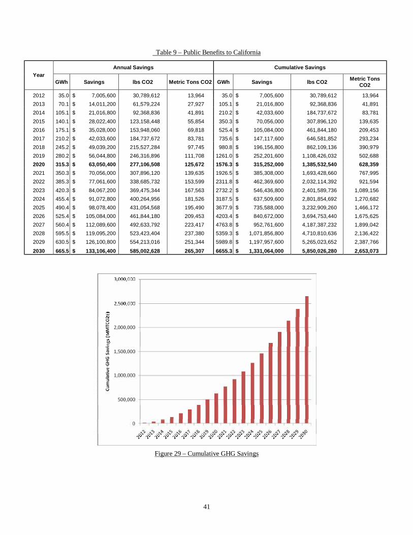
Public Benefits to California The project team estimates the following annual and cumulative savings associated with widespread deployment of Indirect Evaporative Heat Recovery Ventilator technologies in California: By the year 2030, assuming sufficient penetration to produce 665 GWh of annual energy savings, Indirect Evaporative Heat Recovery Ventilator technologies in California are projected to produce $133 million in annual customer energy cost savings and 265 metric tons of CO2 air pollution savings per year. Corresponding cumulative savings are projected to be 6,655 GWh energy, $1.3 billion customer energy cost, and 2.7-million metric tons of CO2 air pollution savings.

5
Introduction Vapor compression air conditioning systems are poorly suited to cooling the large quantities of ventilation air required in retail, school and restaurant applications, particularly in the hot, dry climates of the Western U.S. Indirect evaporative cooling offers a substantial reduction in energy consumption, but prior attempts to market such products have failed due to high system costs and poor reliability. The goal of this project is to develop a unique, low-cost indirect evaporative air-to-air heat exchanger for use in an Indirect Evaporative Heat Recovery Ventilator (IEHRV) to deliver high quality ventilation air while using less than half of the energy of a comparable vapor compression system. The overall goal of this project was to develop an innovative, low-cost evaporative heat exchanger (HX) for use in HVAC equipment such as the Indirect Evaporative Heat Recovery Ventilator (IEHRV). Such equipment will be capable of delivering high quality ventilation air while using less than half of the annual energy and peak demand of a comparable vapor compression system. Successful development and commercialization would provide a long needed alternative to demand-intensive conventional HVAC equipment. Several indirect evaporative heat exchangers are currently available, but high cost, high pressure drop, and/or low performance have limited penetration into the commercial HVAC market. All use the cross-flow configuration, which limits packaging flexibility and results in large cabinets. The IEHRV is shown in Figure 1.
Figure 1: IEHRV Concept

6
In this project, the team tested a sister heat exchanger but was not able to test an IEHRV-HX prototype due to a truncated performance periods, which was caused by external factors at the Energy Commission. However, the team was able to complete the design of the IEHRV-HX plates using computational fluid dynamics, which was calibrated with the test data from the sister product. At the conclusion of the IEHRV-HX project, the thermoforming tooling was completed and prototypes fabricated. The VCEC is an indirect evaporative plate-type heat exchanger that served as the basis for the IEHRV-HX. Both heat exchangers use the same production line and about one-half of the custom VCEC tooling is used for IEHRV-HX manufacturing. The VCEC was developed as part of the HyPak high-efficiency RTU project supported by the National Energy Technology Laboratory (USDOE). The primary difference between the VCEC and the IEHRV-HX is that the VCEC has C-L shaped dry/wet airflow paths (see Figure 2) and the IEHRV-HX will have C-C shaped dry/wet airflow paths (see Figure 1). The subject area for this project was Building Energy.
Project Objectives Project objectives were to:
• Demonstrate indirect evaporative cooling exceeding 50% of the outdoor wet-bulb
depression • Produce heat exchange plate design with CFD simulation results with full-flow
pressure drop of less than 2.0 in WC, and generate 2D dimensional drawing files of final heat exchanger plate design for thermoform tooling.
• Fabricate heat exchanger prototypes.
• Demonstrate indirect evaporative cooling exceeding 60% of the outdoor wet-bulb
depression and full-flow pressure drop less than 1.75 in WC.
• Revise heat exchange plate design with CFD simulation results with full-flow pressure drop of less than 1.75 in WC, and generate 2D dimensional drawing files of final heat exchanger plate design for thermoform tooling.
• Demonstrate indirect evaporative cooling exceeding 70% of the outdoor wet-bulb
depression and full-flow pressure drop less than 1.5 in WC.
• Analyze and produce a final report, including wholesale cost model, followed in due course by submission of an ASHRAE paper.
7
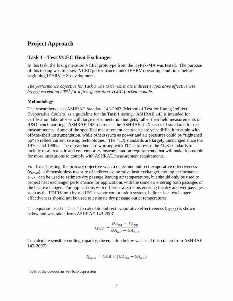
Project Approach Task 1 - Test VCEC Heat Exchanger In this task, the first generation VCEC prototype from the HyPak-MA was tested. The purpose of this testing was to assess VCEC performance under IEHRV operating conditions before beginning IEHRV-HX development. The performance objective for Task 1 was to demonstrate indirect evaporative effectiveness (εEVAP) exceeding 50%1 for a first-generation VCEC flocked module.
Methodology The researchers used ASHRAE Standard 143-2007 (Method of Test for Rating Indirect Evaporative Coolers) as a guideline for the Task 1 testing. ASHRAE 143 is intended for certification laboratories with large instrumentation budgets, rather than field measurements or R&D benchmarking. ASHRAE 143 references the ASHRAE 41.X series of standards for test measurements. Some of the specified measurement accuracies are very difficult to attain with off-the-shelf instrumentation, while others (such as power and air pressure) could be “tightened up” to reflect current sensing technologies. The 41.X standards are largely unchanged since the 1970s and 1980s. The researchers are working with TC1.2 to revise the 41.X standards to include more realistic and contemporary instrumentation requirements that will make it possible for more institutions to comply with ASHRAE measurement requirements. For Task 1 testing, the primary objective was to determine indirect evaporative effectiveness (εEVAP), a dimensionless measure of indirect evaporative heat exchanger cooling performance. εEVAP can be used to estimate dry passage leaving air temperatures, but should only be used to project heat exchanger performance for applications with the same air entering both passages of the heat exchanger. For applications with different airstreams entering the dry and wet passages, such as the IEHRV or a hybrid IEC + vapor compression system, indirect heat exchanger effectiveness should not be used to estimate dry passage outlet temperatures. The equation used in Task 1 to calculate indirect evaporative effectiveness (εEVAP) is shown below and was taken from ASHRAE 143-2007.
To calculate sensible cooling capacity, the equation below was used (also taken from ASHRAE 143-2007).
1 50% of the outdoor air wet-bulb depression

8
For heat recovery effectiveness (εHR), the standard measure of heat exchanger effectiveness based only on dry-bulb temperatures was used.
Test Setup To test the performance of the VCEC, the side-by-side test stand shown in Figure 2 and Figure 3 was constructed.
Figure 2 - Test Setup Schematic

9
Figure 3 - Test Setup
The test stand had two 24” wide VCEC modules installed; one with flocking in the wet passages and one without. The flocking helps to ensure full and even wetting but increases heat exchanger costs. Scale build-up over time has the potential to accomplish the same result as flocking so the researchers set up the test to run both the flocked and unflocked modules side-by-side to evaluate the performance benefit of the flocking. The two systems share controls for identical operating conditions, but each system has its own sump, pump and fans to avoid thermal contamination. Cooling performance testing was focused on the flocked VCEC module. Prior IEHX R&D by the researchers has shown that flocking is a cost-effective solution that lowers supply air temperature significantly. Cooling performance tests are short-term, requiring about 15 minutes of near-steady-state for each test condition. To evaluate the benefit of the flocking, the researchers ran the test stand in automated mode for 5 months. The pumps and fans operated for eight hours per day, with the sump drained each night (as per IEHX controls used by the researchers in prior products). Occasional visual inspections did not show a significant build-up of scale. Test setup fabrication began in August 2007 and required about eight weeks including debugging. The researchers conducted tests runs in late October, but by then ambient conditions were too cool for meaningful evaluation of indirect evaporative cooling. To mimic typical California summer design conditions, two hot water coils at the wet and dry inlets of the flocked VCEC module were installed. A closed-loop hydronic system with a circulator pump and a
VCEC Module
(hidden behind junction box)_ Dry Side Fan (pushing)
Dry Side Inlet Coil
Wet Side Exhaust Fan (pulling; fan hidden)
Wet Passages Airflow
Dry Passages Airflow
Slot for Flow Grids

10
tankless water heater was used to heat ambient air to 95ºF dry-bulb. To compensate for any circuit variations, a manifold to set the flow rate in each aircoil circuit was used. The researchers fitted two fans powered by variable-speed electronically commutated motors (ECM) for each heat exchanger; one to push air through the dry side (forced draft) and one to pull air through the wet side (induced draft). The four motors fans were controlled using analog-to-digital converters to generate the pulse width modulation (PWM) signal required to vary motor speeds. The dry side fan was also mounted in the alternate location to pull air through the dry side to evaluate plate deflection under pressurized and depressurized conditions. Each VCEC module has a dedicated sump with a circulation pump, a fill valve, and a drain valve. The pumps and valves are operated by relays to allow for automated operation. Individual fan motor speed adjustments are made manually using the PWM controllers, with a single relay for automated on/off fan operation at the preset motor speeds. A DataTaker DT50 was used to log data and drive relays. The instrumentation setup is shown in Table 1, Figure 4, Figure 5, and Figure 6.
Table 1 - VCEC Test Instrumentation
Sensor Parameter Description DataTaker DT50 Data
logging A high speed data logger capable of monitoring up to 10 analog (AC, DC, current, voltage, resistance, thermocouple, RTD) and 4 digital signals, 4 digital output channels, 16 bit resolution and up to 10kHz sampling rate
Type T thermocouple grids
Temperature 3x3 thermocouple grids with integral averaging in five locations
Temperature Class B platinum 1000Ω RTD, ±1.0°F accuracy, 4-20mA output
Vaisala HMD60Y (combination duct probe) Relative
humidity Polymer film sensor, ±2% accuracy, 4-20mA output
Energy Conservatory APT-8
Differential pressure
8 channel differential pressure transducer, 0.1Pa resolution, RS-232 interface to PC with real-time + histogram screen display; used to measure pressure drop across dry and wet passages, and to measure Flow Grid pressure drop
Energy Conservatory Flow Grid
Airflow Calibrated perforated plate for minimally invasive in-situ airflow measurements, designed to fit in place of 1” thick air filter. Integral pressure taps are read by the APT-8 and converted to ACFM using provided charts
All of the instrumentation shown in Table 1 was available on-hand, making it unnecessary to expend project budget to purchase or lease instrumentation in Task 1. However, more accurate sensors and a custom flow nozzle box were procured for testing in Tasks 4 and 6.

11
Figure 4 – Instrument Panel
Figure 5 – Instrument Panel
Figure 6 – Instrumentation in Dry Passages
DataTaker DT50
PWM Motor Controllers
Thermocouple Grid
Vaisala
Temp/RH Duct Probes
APT8 Pressure Data Logger

12
Task 2 – Design IEHRV Heat Exchanger Although the first generation VCEC was successful from a performance standpoint, prototype fabrication was difficult. Even though it weighed more than 500 pounds, the early VCEC tooling was a prototype-stage package that lacked internal cooling channels. This limited the number of cycles that could be run before the tooling overheated. In addition, because the tool was so tightly squeezed into the thermoformer (to make the largest-size plates possible), the film had a tendency to come off the toothed chains that pull the material through the thermoforming machine. Because each VCEC (or IEHRV) heat exchanger module requires 34 perfect cycles, the process was frustrating for the thermoforming partner and module costs were high. Heat sealing was done with a foot-operated electric impulse bar sealer, which required three or four operators. Only quarter-modules stacks could be made before the plates would begin to crack from excessive handling. Four quarter-module stacks were then joined and installed the full modules into stainless steel casings. One of these modules was tested in Task 1 of the IEHRV-HX project. Clearly the VCEC and IEHRV sister products needed a faster and more robust production system. In the second phase of the DOE/NETL HyPak-MA project, the project team decided to start from scratch with a new production system that could be used for both products. The HyPak-MA project paid more than $80,000 for new thermoforming tooling and to produce a batch of 12 second-generation VCEC modules. The researchers hired a specialized machine design firm to design and build an automated heat sealing system incorporating twin sets of impulse sealers to seal both the top and bottom of each plate at the same time, costing the HyPak-MA project more than $50,000. Most of the new thermoforming tooling could be re-used for the IEHRV-HX, and the heat sealing equipment accommodates both module types without any modifications. After consultation with the technical manager at the Energy Commission, the team elected to consider these second-generation modules to be technically equivalent to a first-generation IEHRV-HX, given that this development work was benefitting both products equally despite costing the IEHRV-HX project very little. This also made it possible to evaluate the second-generation VCEC in order to learn as much as possible before finalizing the IEHRV-HX design, which essentially mirrors the dry passage of both heat exchangers to for its wet passage. The design of the Task 2 VCEC/IERHV-HX tooling is shown in Figure 7.

13
Figure 7 – VCEC/IEHRV Tool Design

14
Task 3 – Fabricate IEHRV Heat Exchanger The research team selected Irwin R&D of Yakima, WA to fabricate the production-stage thermoforming tooling for the VCEC and IEHRV-HX product, which is shown from Figure 8 to Figure 10. Irwin addressed several deficiencies in earlier tooling:
• A cooling deck was added to both the top and bottom halves, giving precision control over tool temperature.
• An articulated perimeter “sheet clamp” system that holds the plastic film at the center elevation as the top and bottom platens pull the primary geometry away from the film. The sheet clamp also includes a narrow middle section where the center fold geometry is created. This allows the sheet to be clamped down the middle of the tool as well as at the perimeter.
• Removable inserts at the hinge sections to facilitate future design adjustments to this critical area.
• Removable inserts at the alignment features. The team selected Design Services, also of Yakima, WA, to design and fabricate a machine for heat sealing the top and bottom plate edges. The heat sealing station is shown from Figure 11 to Figure 14. The research team designed the corrugated plastic casings, which were made by Amatech Polycell of Erie, PA.
Figure 8 – VCEC/IEHRV Thermoforming Tool (Top Half)

15
Figure 9 – VCEC/IEHRV Thermoforming Tool (Bottom Half)
Figure 10 – VCEC/IEHRV Thermoforming Tool (Bottom Half)

16
Figure 11 – Heat Seal Assembly Station
Figure 12 – Heat seal assembly station.

17
Figure 13 – Flocked, Thermoformed Material in Heat Sealing Station
Figure 14 – Heat-Sealed Heat Exchanger Plates.
18
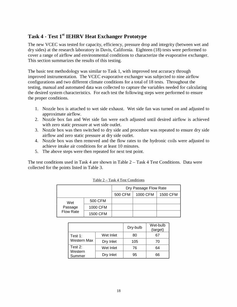
Task 4 - Test 1st IEHRV Heat Exchanger Prototype The new VCEC was tested for capacity, efficiency, pressure drop and integrity (between wet and dry sides) at the research laboratory in Davis, California. Eighteen (18) tests were performed to cover a range of airflow and environmental conditions to characterize the evaporative exchanger. This section summarizes the results of this testing. The basic test methodology was similar to Task 1, with improved test accuracy through improved instrumentation. The VCEC evaporative exchanger was subjected to nine airflow configurations and two different climate conditions for a total of 18 tests. Throughout the testing, manual and automated data was collected to capture the variables needed for calculating the desired system characteristics. For each test the following steps were performed to ensure the proper conditions.
1. Nozzle box is attached to wet side exhaust. Wet side fan was turned on and adjusted to approximate airflow.
2. Nozzle box fan and Wet side fan were each adjusted until desired airflow is achieved with zero static pressure at wet side outlet.
3. Nozzle box was then switched to dry side and procedure was repeated to ensure dry side airflow and zero static pressure at dry side outlet.
4. Nozzle box was then removed and the flow rates to the hydronic coils were adjusted to achieve intake air conditions for at least 10 minutes.
5. The above steps were then repeated for next test point. The test conditions used in Task 4 are shown in Table 2 – Task 4 Test Conditions. Data were collected for the points listed in Table 3.
Table 2 – Task 4 Test Conditions
Dry Passage Flow Rate
500 CFM 1000 CFM 1500 CFM 500 CFM
1000 CFM Wet
Passage Flow Rate 1500 CFM
Dry-bulb Wet-bulb
(target) Wet Inlet 80 67 Test 1:
Western Max Dry Inlet 105 70 Wet Inlet 76 64 Test 2:
Western Summer Dry Inlet 95 66

19
Table 3 – Task 4 Data Points
Abbreviation Description Sensor Type WINRTD Wet passage inlet temperature - RTD WINRH Wet passage inlet relative humidity
Vasiala HMD60Y
WINTC Wet passage inlet temperature - thermocouple Type T thermocouple grid - 3x3 averaging
WINDP Wet passage inlet dew point General Eastern DEW-10 - USED WOUTRTD Wet passage outlet temperature - RTD WOUTRH Wet passage outlet relative humidity
Vasiala HMD60Y
WOUTTC Wet passage outlet temperature - thermocouple Type T thermocouple grid - 3x3 averaging
WOUTDP Wet passage outlet dew point General Eastern DEW-10 - USED WFLWS Wet passage airflow rate SCFM WFLWA Wet passage airflow rate ACFM
ASHRAE Nozzle box
DINRTD Dry passage inlet temperature - RTD DINRH Dry passage inlet relative humidity
Vasiala HMD60Y
DINTC Dry passage inlet temperature - thermocouple Type T thermocouple grid - 3x3 averaging
DINDP Dry passage inlet dew point General Eastern DEW-10 - NEW DOUTRTD Dry passage outlet temperature - RTD DOUTRH Dry passage outlet relative humidity
Vasiala HMD60Y
DOUTTC Dry passage outlet temperature - thermocouple Type T thermocouple grid - 3x3 averaging
DOUTDP Dry passage outlet dew point General Eastern DEW-10 - NEW DFLWS Dry passage airflow rate SCFM DFLWA Dry passage airflow rate ACFM
ASHRAE Nozzle box
PDDRY Dry passage pressure drop dry inlet dry outlet PDWET Wet passage pressure drop wet inlet wet outlet
DRYINST Dry passage inlet static pressure dry inlet open
DRYEXST Dry passage exit static pressure dry exit open
WETINST Wet passage inlet static pressure wet inlet open
WETEXST Wet passage exit static pressure wet exit open
Energy Conservatory APT-8
Channel A Channel B

20
Task 5 – Revise IEHRV Heat Exchanger
Overview With the promising test results from Task 4 in-hand, the researchers designed the IEHRV wet passage plate to mimic the C shaped dry passage used by both the VCEC and IEHRV. Design challenges were related to water distribution. Unlike the dry passage, the wet passage can’t have wide horizontal geometry or the area under such geometry would be starved of water, and thermal performance would suffer. The researchers conducted more than 25 CFD simulations of the IEHRV-HX wet passage, with a total CPU time of more than 150 hours. In addition to the new wet passage geometry, Irwin made several other changes to the base VCEC/IEHRV tooling:
• More aggressive hinge geometry for easier handling. • Interlocking alignment features to improve seal reliability and reduce handling
requirements. • Changes to the base platens to simplify mold change-out.
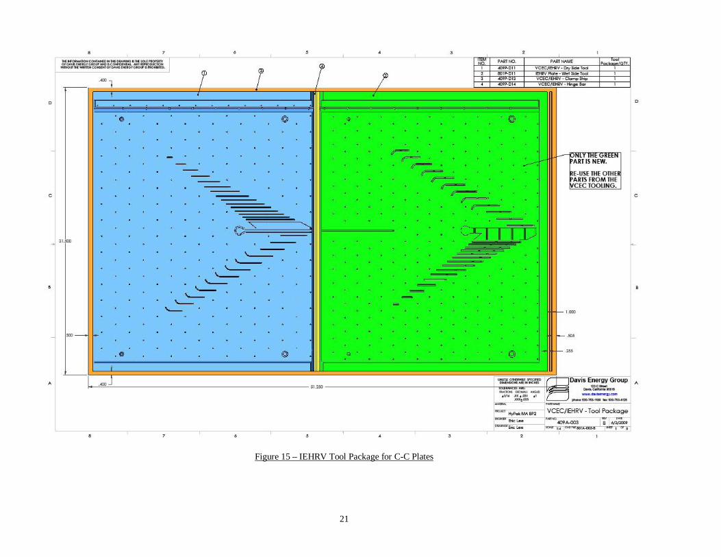
The revised VCEC/IERHV-HX tooling is shown in Figure 15 and Figure 16. Design Services revised the sealing equipment to operate at 240 VAC instead of 120 VAC, which had required Pride Polymers to operate only one side of the sealer at a time. The casings were redesigned to accommodate the IEHRV airflow configuration, as shown from Figure 17 to Figure 19. Amatech Polycell made new casings for IEHRV-HX.
21
Figure 15 – IEHRV Tool Package for C-C Plates

22
Figure 16 – IEHRV Tool Package for C-C Plates

23
Figure 17 – IEHRV Casing Assembly

24
Figure 18 – IEHRV Casing (Dry End)

25
Figure 19 – IEHRV Casing (Wet End)

26
Task 6 – Test 2nd IEHRV Heat Exchanger Prototype Because of a truncated performance period (due to external factors at the Energy Commission), the team was not able to test the final Evaporative Heat Recovery Ventilator Heat Exchanger modules. The researchers intends to test the production-ready IEHRV prototypes later in 2009 or 2010, most likely with Energy Commission and/or DOE support through the American Recovery and Reinvestment Act (ARRA) of 2009. Formal solicitations have not yet been issued, but the research team is already preparing a proposal to continue funding of VCEC/IEHRV-HX RD&D. This will include both IEHRV-HX testing and development of the balance of the IEHRV unit. Testing will mostly follow the methodology developed and discussed in Task 4, but will also include zero flow tests shown in Table 4 to determine maximum deflection and pressure drop effects of using only one side of the HX. See.
Table 4 - Flow Rates
Dry Passage Flow Rate
0 CFM 500 CFM 1000 CFM 1500 CFM 0 CFM
500 CFM 1000 CFM
Wet Passage
Flow Rate 1500 CFM
Task 7 – Analyze and Report
• The cost target for the IEHRV-HX project was the EPX heat exchanger produced by Des Champs Technologies, now a part of Munters. Direct costs for the EPX are about $2 per CFM.
• The project final report is embodied herein.
• The ASHRAE Paper will be composed and submitted for publication in due course.
Publication cycles are nine to twelve months from development of abstract.

27
Project Outcomes
Task 1 testing showed indirect evaporative effectiveness in excess of 70%, surpassing the first project objectives of 50% indirect effectiveness.
Results of the indirect evaporative cooling tests in Task 1 are shown in Table 5.
Table 5 - Indirect Cooling Test Results
Dry Side Entering OA Wet Side Entering OA
Temperature Temperature VCEC Module
Type Test Type
Air
flow
(A
CFM
)
Dry-bulb (°F)
Wet-bulb (°F) A
irflo
w
(AC
FM)
Dry-bulb (°F)
Wet-bulb (°F)
Dry Side Leaving SA Dry-
bulb Temp.
(°F) Cap
acity
, QSe
ns
(BT
U/h
r)
Indi
rect
E
vapo
rativ
e E
ffect
iven
ess,
ε EV
AP
600 95.0 65.5 600 94.7 65.7 68.6 17,112 89.6%
900 95.0 64.4 900 94.9 65.1 70.6 23,684 79.8%
1200 95.2 64.3 1200 95.1 65.1 70.6 31,882 79.7%
Balanced Wet/Dry Airflows
1500 90.5 62.6 1500 90.9 63.9 68.6 35,478 78.3%
Flocked
Half Wet Flow 1200 95.0 61.2 600 95.0 62.1 73.0 28,51
2 65.1%
Unflocked Balanced Airflows 1200 76.5 55.8 1200 76.5 55.8 72.5 5,172 19.3%
The green entries in Table 5 show the flow conditions that expected to be the most common for the IEHRV-HX. As expected, the lowest flow rate (600 ACFM) had the highest effectiveness, but all three of the higher flow rates were within the margin of error of each other. Higher flow rates have lower average dwell time, which reduces heat exchange. However, the higher flow rates have more turbulence, which increases heat transfer coefficient to offset much of the impact of shorter dwell time. As expected, the flocked modules exhibited substantially higher effectiveness than the un-flocked modules, shown in the orange entries in Table 5. Hopefully the un-flocked module effectiveness will increase as scale builds up in the wet passages to help more even water distribution. The un-flocked modules were run 8 hours a day and were re-tested for effectiveness after about 5 months of use to evaluate the efficacy of scale build-up as a replacement for flocking. This test showed that the flocked material was far superior in performance and that the scale build-up strategy was unsuccessful. All data shown in Table 5 are for test runs conducted with the hot water coils operational. Ambient conditions were 55ºF-60ºF during those tests. Because the test setup is not insulated, the cooler ambient temperatures likely helped increase indirect cooling effectiveness slightly.

28
Task 2 Computational fluid dynamics predicted pressure drop of 1.5 inWC, surpassing the second project objectives of 2.0 inWC. Task 1 testing confirmed this with a pressure drop of 1.25 inWC.
One of the drawbacks to some existing indirect evaporative cooling technologies is high pressure drop. More pressure drop means more fan energy is required to push or pull air through the heat exchanger, driving down EER ratings. The optimal heat exchanger design will need to balance pressure drop versus indirect effectiveness. Therefore, pressure drop across the VCEC was measured for a variety of flow rates and two fan configurations; one with the fan for the dry passages pushing as shown in Figure 1 and one with the fan positioned on the dry passage outlet to pull air through the dry passages. Pressure and flow data for the dry passage are shown in Figure 20, including both experimental data from IEHRV-HX Task 1 testing and theoretical data from the Task 2 CFD simulations. In addition, data from VCEC testing at Des Champs Technologies (now a part of Munters) from 2007 is included in the graph.
Figure 20 - VCEC Dry Passage Pressure Drop v. Flow Rate
The CFD simulations require that the passage be modeled using either laminar or turbulent flow. Reynolds number calculations indicate that all of the dry passages are turbulent under all circumstances, except for possibly in the dry passage corners at 600 CFM/module flow. The DCT testing appears to correlate well with the turbulent CFD predictions, while the Task 1 testing appears to match the laminar flow better. The discrepancy between the DCT and Task 1 testing may be due to airflow rate measurement error in the Flow Grids. (DCT uses flow nozzles

29
to measure airflow rates.) The researchers believe that the Flow Grids overstated the airflow rate. For practical applications, actual flow should be somewhere between the lines shown on Figure 6. The difference between the data for the dry passage fan pushing (forced draft) and pulling (induced draft) is likely due to deflection of the plate causing the dry passages to close down slightly with the fan pulling, and blowing open slightly with the fan pushing. For IEHRV applications, the dry passage fan is likely to be pushing. For HyPak VCEC applications, the dry passage fan will be pulling. A similar comparison of theoretical and experimental data for the wet passage is shown in Figure 21. In this case, the experimental data predicted more pressure drop than the CFD for a given flow rate. Once again, the wet passage showed a small impact on the pressure drop due to plate deflection.
Figure 21 - VCEC Wet Passage Pressure Drop v. Flow Rate (flocked module)
Selected output from the Task 2 computational fluid dynamics modeling is shown in Figure 22, Figure 23, and Figure 24.
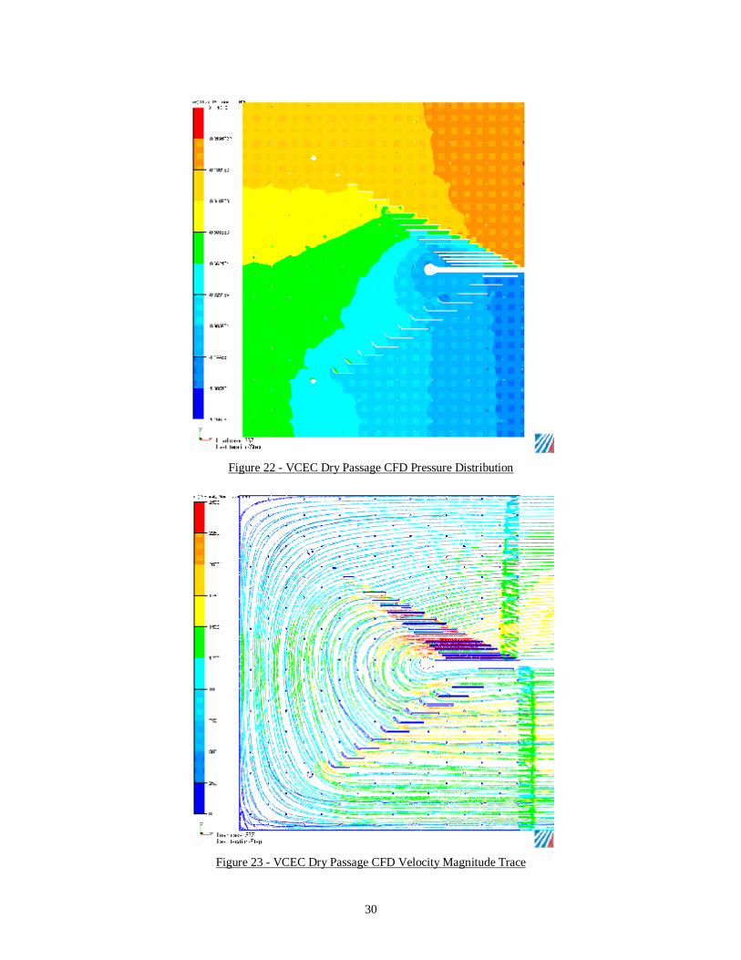
30
Figure 22 - VCEC Dry Passage CFD Pressure Distribution
Figure 23 - VCEC Dry Passage CFD Velocity Magnitude Trace

31
Figure 24 - VCEC Dry Passage CFD Velocity Magnitude Distribution
12 VCEC and IEHRV-HX prototypes were fabricated in Task 3.
A Task 3 prototype is shown in Figure 25.
Figure 25: Task 3 VCEC and IEHRV-HX Prototype
32
Task 4 testing showed indirect evaporative effectiveness in excess of 70% and pressure drop of 0.85 inWC at 1500 CFM, surpassing the fourth project objective of 60% indirect effectiveness and less than 1.75 inWC.
The results of Task 4 testing are shown in Table 6. The calculated capacity ranged between 2 and 3 tons, with EER values from 15 to well over 30. The wet bulb depressions were larger than the test goals. All previous lab testing was done in Virginia, and the small wet bulbs achieved led us to underestimate the capabilities of the VCEC. In the dry Davis, California climate, the wet bulb depression and the dry bulb reduction in temperature was far greater than initial testing. Using sensible temperature change and airflow calculations, capacities ranged from 2.3 to 3.7 tons with maximum dry side air. When the capacity was calculated using enthalpy and wet bulb values, the range was from 0.7 to 2.4 for the maximum airflow condition. Using the sensible temperature method to calculate efficiencies yielded EER values that rarely dip below 30. When the enthalpy method was used, the EER values dropped to around 15 and above with the occasional lower value. In both cases, the EER values were the highest when the dry side air was at 500 scfm. The enthalpy calculations use 2%-accuracy Vaisala RH sensors, which are less accurate than the chilled mirror sensors. There was some unreliable data from the critical dry side output dew point chilled mirror sensor, so that data could not be used, which would be much more accurate. It was unfortunate because the chilled mirror sensors read out dew point temperature directly, which makes it easy to determine if the wet side is leaking moist air into the dry airstream. Technicians stated that during early test runs, when the dry side sensor was working, it indicated that there was little or no leakage.

33
Table 6 – Task 4 Test Results VCEC April 2009 Testing
1 2 3 4 5 6 7 8 9 10 11 12 13 14 15 16 17 18TestDry Nom AirWet Nom Air 1500 1000 500 1500 1000 500 1500 1000 500 1500 1000 500 1500 1000 500 1500 1000 500Date 4/24/2009 4/27/2009 4/27/2009 4/24/2009 4/23/009 4/23/2009 4/24/2009 4/24/2009 4/24/2009 4/24/2009 4/27/2009 4/27/2009 4/24/2009 4/23/2009 4/23/2009 4/24/2009 4/27/2009 4/22/2009Time 4:10 PM 3:37 PM 2:40 PM 2:58 PM 1:57 PM 4:02 PM 11:45 AM 10:17 AM 8:52 AM 5:02 PM 5:03 PM 1:05 PM 2:06 PM 12:44 PM 11:11 AM 12:59 PM 10:52 AM 9:56 AM
Airflow (SCFM) 1427 1395 1396 998 1007 1020 499 510 517 1434 1403 1400 1004 1009 998 519 517 500Din DbT 105.1 105.1 105.7 105.4 104.9 105.2 105.0 105.8 105.5 95.0 96.3 95.1 95.1 96.0 92.1 96.0 96.2 94.8Din WbT 64.6 66.2 66.6 64.6 67.6 67.8 64.3 64.8 64.9 61.1 62.5 62.8 58.0 64.7 63.9 58.6 63.5 67.6Din DP 34.3 40.2 40.9 33.6 44.9 45.0 33.0 33.9 34.7 33.6 37.2 39.5 19.6 44.4 45.6 21.4 40.5 52.6Din enthalpy (btu/lb) 29.8 31.0 31.3 29.8 32.1 32.3 29.5 29.9 30.0 27.2 28.2 28.4 25.1 29.9 29.2 25.6 29.0 32.1Dout DbT 75.9 78.1 82.6 72.1 76.8 70.7 65.9 67.9 70.7 71.6 73.9 77.0 65.0 71.2 74.5 62.0 67.0 74.2Dout Wbt 58.4 61.7 63.7 56.3 63.1 58.9 52.9 54.2 56.2 55.6 58.5 60.9 50.5 61.2 63.0 48.4 56.1 63.9Din DP 45.9 51.7 52.7 44.4 55.1 51.1 42.1 43.4 45.4 43.0 47.8 50.6 36.9 55.3 56.4 34.9 48.3 58.4Din enthalpy (btu/lb) 25.4 27.7 29.1 24.1 28.6 25.7 22.0 22.8 24.0 23.6 25.5 27.1 20.6 27.3 28.5 19.5 23.9 29.2%Eff w.r.t. Din WbT 72% 70% 59% 82% 75% 92% 96% 92% 86% 69% 66% 56% 81% 79% 62% 91% 89% 76%Capacity (btu/hr) 44,983 40,737 34,879 35,908 30,463 37,976 21,054 20,894 19,395 36,218 33,853 27,299 32,633 27,088 18,905 19,086 16,318 11,144Capacity (tons) 3.7 3.4 2.9 3.0 2.5 3.2 1.8 1.7 1.6 3.0 2.8 2.3 2.7 2.3 1.6 1.6 1.4 0.9Capacity (btu/hr) 28,275 21,086 13,917 25,473 15,949 30,064 16,909 16,336 13,898 23,470 17,523 8,498 20,526 11,673 3,147 14,289 11,720 6,349Capacity (tons) 2.4 1.8 1.2 2.1 1.3 2.5 1.4 1.4 1.2 2.0 1.5 0.7 1.7 1.0 0.3 1.2 1.0 0.5∆P (inWC) 0.82 0.85 0.84 0.42 0.44 0.44 0.12 0.12 0.13 0.82 0.85 0.84 0.42 0.44 0.44 0.12 0.12 0.13Fan power (watts) 908 962 972 388 394 405 64 64 64 908 962 972 388 394 405 64 64 64
Airflow 1468 1008 502 1481 1011 503 1481 1016 504 1474 1012 501 1490 1013 459 1490 1011.0 500Win DbT 80.6 80.4 80.1 80.0 79.9 80.1 80.6 79.9 80.2 76.0 76.1 75.3 75.9 76.0 74.8 76.0 76.1 77.7Win WbT 58.9 61.0 61.1 58.3 63.6 62.8 57.6 58.4 59.6 56.6 57.9 58.4 51.8 61.0 62.6 52.4 59.3 66.9Wout DbT 69.2 73.2 77.6 67.9 74.0 70.8 64.2 65.9 67.6 66.5 69.3 72.9 61.1 68.0 71.2 59.0 65.8 69.6Wout Wbt 65.1 69.6 73.3 63.4 69.2 65.9 60.5 63.4 63.1 62.3 66.0 68.5 56.8 65.1 67.6 55.2 62.6 69.0%Eff w.r.t. Win WbT 63% 61% 52% 71% 68% 81% 82% 80% 76% 61% 58% 49% 70% 71% 59% 78% 79% 74%∆P (inWC) 0.92 0.40 0.08 0.87 0.34 0.08 0.79 0.32 0.08 0.92 0.40 0.08 0.87 0.34 0.08 0.79 0.32 0.08Fan power (watts) 575 185 33 550 152 24 499 158 23 575 185 33 550 152 24 499 158 23Pump power (watts) 26 26 26 26 26 26 26 26 26 26 26 26 26 26 26 26 26 26
Total power (watts) 1509 1173 1031 964 572 455 589 248 113 1509 1173 1031 964 572 455 589 248 113EER (sensible calc) 29.8 34.7 33.8 37.2 53.3 83.5 35.7 84.2 171.6 24.0 28.9 26.5 33.9 47.4 41.5 32.4 65.8 98.6EER (enthalpy calc) 18.7 18.0 13.5 26.4 27.9 66.1 28.7 65.9 123.0 15.6 14.9 8.2 21.3 20.4 6.9 24.3 47.3 56.2
500
Overall
Western Max (OA = 105/67, RA = 80/60)1500 1000 500
Dry Side
Wet Side
Western Summer (OA = 95/63, RA = 76/58)1500 1000
34
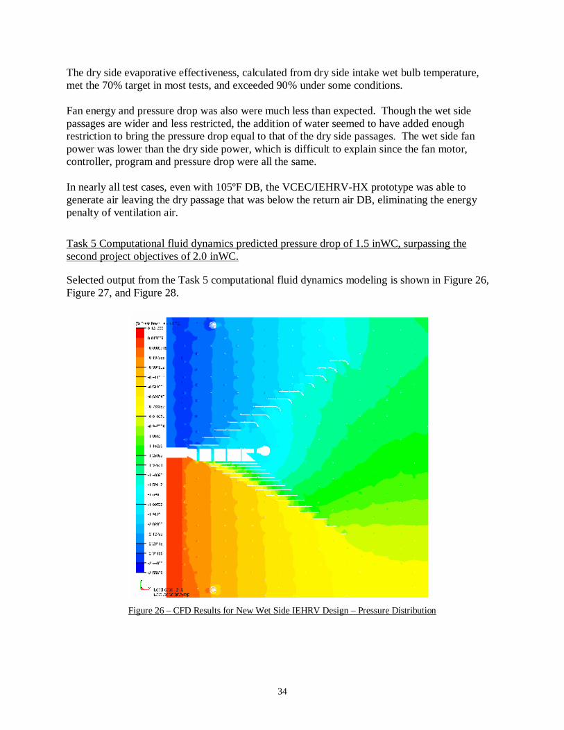
The dry side evaporative effectiveness, calculated from dry side intake wet bulb temperature, met the 70% target in most tests, and exceeded 90% under some conditions. Fan energy and pressure drop was also were much less than expected. Though the wet side passages are wider and less restricted, the addition of water seemed to have added enough restriction to bring the pressure drop equal to that of the dry side passages. The wet side fan power was lower than the dry side power, which is difficult to explain since the fan motor, controller, program and pressure drop were all the same. In nearly all test cases, even with 105ºF DB, the VCEC/IEHRV-HX prototype was able to generate air leaving the dry passage that was below the return air DB, eliminating the energy penalty of ventilation air. Task 5 Computational fluid dynamics predicted pressure drop of 1.5 inWC, surpassing the second project objectives of 2.0 inWC.
Selected output from the Task 5 computational fluid dynamics modeling is shown in Figure 26, Figure 27, and Figure 28.
Figure 26 – CFD Results for New Wet Side IEHRV Design – Pressure Distribution

35
Figure 27 – CFD Results for Wet Side IEHRV Design - Velocity Magnitude Trace
Figure 28 – CFD Results for Wet Side IEHRV Design - Velocity Magnitude Distribution

36
Because final prototypes were not completed by the time of this report, the researchers were unable to complete the sixth project objective. (The performance period was truncated due external events.)
This report, including a wholesale cost model, was prepared. The researchers were unable to complete an ASHRAE paper during the truncated period of performance, but plan to afterwards. With this exception, the final project objective was met.
The IEHRV-HX costs are shown in Table 7 and Table 8. Prototype costs are taken directly from Task 5 of the current project. Volume costs are based on quotes and expected improvements in integrating the thermoforming and sealing operations. Volume costs assume annual production of 1000 modules per year. Current IEHRV-HX pricing undercuts the EPX heat exchanger by almost 50%. Moderate sales success at that price level should ensure the volume costs are achieved, leading to a wholesale price reduction of 80% from current HVAC industry offerings. This will lead to a reduction in efficient HVAC equipments and encourage higher rates of ventilation for improved occupant health.
Table 7 - Prototype Pricing
Item Cost per IEHRV module Notes
Materials HIPS flocked
material $142.00 $2.84/yard x 50 yards per module
Casing $34.40 Labor
Thermoforming $300.00 2 hours per module @ $150/hour Sealing $225.00 5 hours per module @ $45 Install into casing $90.00 2 hours per module @ $45
Direct costs subtotal $791.40 Gross profit margin 50% Wholesale price $1,582.80 Price per CFM $1.06 1500 CFM per module

37
Table 8 - Volume Production Pricing
Item Cost per IEHRV module Notes
Materials HIPS flocked
material $106.50 $2.13/yard x 50 yards per module
Casing $10.40 corrugated plastic only (no labor) Labor
Thermoforming $225.00 1.5 hours per module @ $150/hour Sealing $70.00 2 hours per module @ $35/hour Fabricate casing $8.75 0.25 hours per casing $35/hour Install into casing $70.00 1 hour per module @ $35/hour
Direct costs subtotal $490.65 Gross profit margin 30% Wholesale price $700.93 Price per CFM $0.39 1800 CFM per module
Conclusions
• Task 1 test data showed a surprisingly high indirect evaporative effectiveness for the first-generation VCEC (developed in the HyPak-MA project) significantly exceeding the first project objective. However, the prototype tooling used to fabricate the first generation VCEC was incompatible with volume production.
• The researchers redesigned the VCEC/IEHRV-HX plates to improve manufacturability and reduce pressure drop. Computational Fluid Dynamics confirmed that the pressure drop in both passages was 1.5 inWC, surpassing the second project objective by 25%.
• The research team designed and fabricated precision thermoforming tooling capable of volume production for the VCEC/IEHRV-HX in Task 3. The modular tooling design maximizes flexibility and makes it easier to adjust the tooling to improve manufacturability or module performance. The research team also designed and fabricated a semi-automated sealing station to heat-seal the edges of the fan-folded heat exchangers. Although some problems were encountered when using the new equipment, the research team produced 12 VCEC/IEHRV-HX prototypes.
• Task 4 testing of these modules once again showed an indirect evaporative effectiveness of 70% or more. This time, the pressure drop was even lower at 0.8 inWC, surpassing the fourth objective by more than 50%.
• In response to the problems encountered in Task 3, the research team made several refinements to the thermoforming and heat sealing equipment. Taking advantage of the modular design of the tooling package, a portion of the tooling was rebuilt to match the
38
airflow configuration of the IEHRV-HX. The research team fabricated six IEHRV-HX modules.
• Because the project performance period was truncated due to external factors, the researchers were unable to test these final pre-production IEHRV-HX modules. The researchers are seeking additional funding to conduct this testing.
• A wholesale cost model was developed for both pilot production and volume production. Although the IEHRV-HX project was terminated early under challenging circumstances, the project team demonstrated that this technology has significant technical and economic promise. Test results showed that the IEHRV-HX technology eliminates the energy penalty of ventilation air by consistently generating supply air that was cooler than the return air. By combining the resources of the HyPak-MA/VCEC and IEHRV-HX project, the team was able to develop this innovative fan-folded plastic air-to-air heat exchanger technology beyond what would have been possible through either of the projects operating independently. The production system is highly evolved and will enable the project team to transition from the R&D phase to the demonstration phase of the IEHRV-HX, and to shift development to the balance of IEHRV. Commercialization of the IEHRV-HX is expected to take the following approach:
• The IEHRV-HX will serve as the core technology for the Indirect Evaporative Heat Recovery Ventilator (IEHRV), which will also include supply and exhaust fans, a pump and water manifold, controls, and cabinet. The cabinet may be rotationally molded polyethylene. Without a vapor compression system, IEHRV marketing will focus on two areas:
o Zones that are not currently served by vapor compression cooling. In the extreme hot/dry climates where the IEHRV will have the highest efficiency, these zones will only be warehouse of manufacturing space, which are either unconditioned, or have only direct evaporative coolers. Displacing vapor compression system is possible in the coastal and near-coastal areas of California, but it will be “tough sledding” until the HVAC industry is convinced of the IEHRV performance and reliability through better-suited applications.
o Paired with an air-cooled RTU for latent cooling. With the IEHRV handling the ventilation air requirement, the RTU can be performance- and cost-optimized for 100% return air operation. In big-box retail, where most of the store is a single zone served by 2-10 RTUs, dedicated 100% OA (DOAS) RTUs and 100% RA RTUs are the norm. Lower-cost IEHRVs with single-speed motors will fit this application well; unlike current DOAS units which are sized for at least 6000 CFM, the IEHRV will be suitable for zones with as little as 1500 CFM VA required, or even lower if additional VA is desired for better IAQ. This arrangement makes it possible to shut the RTU supply fan off completely whenever there isn’t a call for cooling.

39
• An expected follow-on product will be a hybrid IEHRV that includes a small vapor compression system. Then the IEHRV technology can be applied to zones that have total supply airflow rates of 1500 CFM, rather than just those with ventilation airflow components of 1500 CFM (and 3000 to 7500 CFM total). With an industry standard of 400 CFM/ton, 1500 CFM SA equipment will typically deliver 3.75 tons of cooling capacity at rating conditions, and 3.2 tons at design conditions. This puts the hybrid IEHRV squarely in the 2-5 ton RTU segment, which makes up more than half of the total RTU market, and where most efficiency measures have not been able to make inroads. Comfort is expected to exceed current air-cooled vapor compression systems at design conditions.
• IEHRV-HX modules will also be sold to other HVAC manufacturers to incorporate in their own products. With air-cooled vapor compression nearing the theoretical limit of efficiency (estimated at 20 EER), and also the associated peak demand and comfort issues, governments and utilities will increasingly look to evaporative HVAC for additional savings. The researchers believe that manufacturers will also be pressured by regional HVAC standards likely to come from DOE in the next few years.
Recommendations The research team is ready to continue IEHRV and IEHRV-HX development. Possible topic areas for future R&D include:
• Development of a 1500 CFM Indirect Evaporative Heat Recovery Ventilator (IEHRV). Such a system would use two 1.0 HP motors, which is the largest size available in electronically commutated motors (ECMs). ECMs are affordable and efficient variable speed motors that operate on single-phase power, making this IEHRV compatible with small commercial applications. The cabinet will likely be rotationally molded from polyethylene with integrated fan shrouds for lower cost and to eliminate corrosion.
• Development of a hybrid version of the 1500 CFM IEHRV including a small vapor compression system.
• Development of a simple, low-cost, 6000-8000 CFM IEHRV for commercial DOAS (dedicated outdoor air system) applications in hot/dry climates. DOAS systems were pioneered in the Southeastern U.S., where they have large latent loads associated with ventilation air, even when there is little or no sensible cooling load. Conventional HVAC systems tackle this situation by dehumidifying with the vapor compression system and then electric or gas re-heat to avoid excessive cooling. Traditional DOAS systems include desiccant-based latent recovery systems. DOAS manufacturers have only recently begun to develop products optimized for the hot/dry climate, where the load imbalance is reversed. Particularly for high-VA zones, there is little or no latent load during peak operation. This is a significant market opportunity for a DOAS system that relies solely on indirect evaporative cooling, leaving the 100% RA RTUs to handle the occasional latent load. (A big-box retail store will have 40 tons of DOAS and 120 tons of

40
conventional RTUs.) Therefore, a key component for the proposed indirect evaporative RD&D program is a hot/dry DOAS unit capable of 6000-8000 CFM that could be used for big-box applications across California. This remarkably simple unit would require only two fans and motors, a pump and water distribution systems, filter rack, basic controls, and four IEHRV-HX modules. By eliminating the cost and complexity of the vapor compression system, this DOAS IEHRV-HX should offer similar capacity to existing DOAS units at air-cooled RTU prices, while offering class-leading EERs. Construction will use conventional steel cabinets and mounting curbs.
• Field demonstrations of either the small or large IEHRV.
• Continued refinement of the VCEC/IEHRV production line to: o Improve heat seal reliability o Optimize fold geometry o Develop a cassette system to transport fan-folded material from the thermoformer
to the heat sealer o In-house fabrication of corrugated plastic casings (at Pride Polymers)
At the time of this writing, the team is investigating a request for proposals for Department of Energy/National Energy Technology Laboratory, American Recovery and Reinvestment Act stimulus funding to further research, development and demonstration of indirect evaporative technologies. They may also submit a proposal to develop the 1500 CFM IEHRV to future Energy Commission BERG solicitations.
Public Benefits to California The project team used the following assumptions to estimate public benefits to California from IEHRV-HX R&D and commercialization:
• Conservatively assume IEHRV-HX technologies are only implemented in new construction.2
• Assume average EER is 25.0 for IEHRV • Assume average EER is 12.0 for air-cooled RTUs • Assume 60% penetration in RTU market for new construction (36% of total non-
residential in California) • 2,919 GWh projected energy use of newly constructed buildings, non-residential in
California3 • California average greenhouse gas content of electricity is 0.879 lbCO2/kWh4 • $0.20/kWh energy costs (adjusted upward from estimated current average commercial
rate of $0.12/kWh to account for future rate increases and reduced demand charge for IEHRV)
2 The team expects to market the IEHRV to both retrofit and new construction markets. However, compatibility with pre-existing duct and curb systems will be a market barrier. 3 2008 Update to the CEC Standards for Res and Non-res Buildings, AEC 4 http://www.eia.doe.gov/oiaf/1605/coefficients.html
41
Table 9 – Public Benefits to California
Annual Savings Cumulative Savings Year
GWh Savings lbs CO2 Metric Tons CO2 GWh Savings lbs CO2 Metric Tons CO2
2012 35.0 $ 7,005,600 30,789,612 13,964 35.0 $ 7,005,600 30,789,612 13,964 2013 70.1 $ 14,011,200 61,579,224 27,927 105.1 $ 21,016,800 92,368,836 41,891 2014 105.1 $ 21,016,800 92,368,836 41,891 210.2 $ 42,033,600 184,737,672 83,781 2015 140.1 $ 28,022,400 123,158,448 55,854 350.3 $ 70,056,000 307,896,120 139,635 2016 175.1 $ 35,028,000 153,948,060 69,818 525.4 $ 105,084,000 461,844,180 209,453 2017 210.2 $ 42,033,600 184,737,672 83,781 735.6 $ 147,117,600 646,581,852 293,234 2018 245.2 $ 49,039,200 215,527,284 97,745 980.8 $ 196,156,800 862,109,136 390,979 2019 280.2 $ 56,044,800 246,316,896 111,708 1261.0 $ 252,201,600 1,108,426,032 502,688 2020 315.3 $ 63,050,400 277,106,508 125,672 1576.3 $ 315,252,000 1,385,532,540 628,359 2021 350.3 $ 70,056,000 307,896,120 139,635 1926.5 $ 385,308,000 1,693,428,660 767,995 2022 385.3 $ 77,061,600 338,685,732 153,599 2311.8 $ 462,369,600 2,032,114,392 921,594 2023 420.3 $ 84,067,200 369,475,344 167,563 2732.2 $ 546,436,800 2,401,589,736 1,089,156 2024 455.4 $ 91,072,800 400,264,956 181,526 3187.5 $ 637,509,600 2,801,854,692 1,270,682 2025 490.4 $ 98,078,400 431,054,568 195,490 3677.9 $ 735,588,000 3,232,909,260 1,466,172 2026 525.4 $ 105,084,000 461,844,180 209,453 4203.4 $ 840,672,000 3,694,753,440 1,675,625 2027 560.4 $ 112,089,600 492,633,792 223,417 4763.8 $ 952,761,600 4,187,387,232 1,899,042 2028 595.5 $ 119,095,200 523,423,404 237,380 5359.3 $ 1,071,856,800 4,710,810,636 2,136,422 2029 630.5 $ 126,100,800 554,213,016 251,344 5989.8 $ 1,197,957,600 5,265,023,652 2,387,766
2030 665.5 $ 133,106,400 585,002,628 265,307 6655.3 $ 1,331,064,000 5,850,026,280 2,653,073
Figure 29 – Cumulative GHG Savings

42
The resulting projections by year for all IEHRV technologies are shown in Table 9 (assuming widespread availability in 2012) with cumulative greenhouse gas emissions reductions shown in Figure 29. With the AB32 Scoping Plan5 calling for a reduction of 169,000,000 metric tons by 2020, the IEHRV can provide 0.7% of the total required savings. To put this into perspective, the Scoping Plan calls for a 1.0 MMTCO2E from extreme penetration (15% of all residential units) of solar water heating. If the IEHRV is able to convert large amounts of existing buildings to the DOAS cooling configuration (with an IEHRV unit handling all ventilation loads), savings could easily be ten times as large at the new construction market, making the IEHRV a key technology in California’s climate change strategy.
5 California Air Resources Board, http://www.arb.ca.gov/cc/scopingplan/scopingplan.htm

43
Glossary ACFM Actual airflow in cubic feet per minute ARRA American Recovery and Reinvestement Act ASHRAE American Society of Heating, Refrigeration and Air-Conditioning Engineers, Inc. BERG CEC Building Energy Research Grant CEC California Energy Commission CFD Computational Fluid Dynamics DEG Davis Energy Group DOAS Direct Outdoor Air System DOE US Department of Energy Dry Bulb Temperature Sensible air temperature
EER Energy efficiency ratio EPX Munters brand cross-flow indirect evaporative heat exchanger
Flocking Small fibers applied to a surface to reduce water surface tension and increase distribution of water uniformly over a surface.
HVAC Heating, Ventilation and Air Conditioning HX Heat exchanger
HyPak-MA A high efficiency package unit developed by DEG that combines evaporative condenser cooling and vent air cooling into the same module.
IAQ Indoor air quality IEC Indirect Evaporative Cooler IEHRV Indirect evaporative heat recovery ventilator IEHX Indirect evaporative heat exchanger NETL National Energy Technology Laboratory OA Outdoor Air
Platen Heavy plates mounted to the thermoforming machine that recieve the tooling plates with part details.
R&D Research and Development RA Return Air RD&D Research, Development and Demonstration RTD Resistance Temperature Detector RTU Rooftop Unit SA Supply Air SCFM Airflow adjusted to standard conditions (in cubic feet per minute) SDSURF San Diego State University Research Foundation VA Ventilation Air VCEC Vertical counterflow evaporative cooler WC Water column (measure for pressure, usually in inches) Wet Bulb Temperature
A temperature measurement of an air volume that reflects the capacity of the air to receive water vapor.
.

California Energy Commission Building Energy Research Grant (BERG) Program PROJECT DEVELOPMENT STATUS
Development Status Questionnaire
PI Name Eric Lee Grant # 55183A/07-02B
Overall Status Questions Comments:
1) Do you consider that this research project achieved the goal of your concept?
Yes. The researchers were able to demonstrate the performance and cost advantage of the heat exchanger.
2) Do you intend to continue this development effort towards commercialization?
Yes.
Engineering/Technical 3) What are the key remaining technical or
engineering obstacles that prevent product demonstration?
Water leakage; cost of assembly (labor and materials) is still too high.
4) Have you defined a development path from where you are to product demonstration?
Yes.
5) How many years are required to complete product development and demonstration?
One to two.
6) How much money is required to complete engineering development and demonstration?
$400 to $500k.
7) Do you have an engineering requirements specification for your potential product?
No. This will require one year of further R&D.
Marketing 8) What market does your concept serve? Commercial.
9) What is the market need? Energy efficient, low cost cooling. Reduction in energy penalty for increase ventilation air.
10) Have you surveyed potential customers for interest in your product?
Ongoing.
11) Have you performed a market analysis that takes external factors into consideration?
No.
12) Have you identified any regulatory, institutional or legal barriers to product acceptance?
Yes. Flame and smoke spread requirements will have to be met. With several plastic heat exchangers already on the market, this is not a significant barrier.
13) What is the size of the potential market in California for your proposed technology?
60% of commercial new construction uses RTU units. The researcher estimate a 60% penetration into that market, or 36% of the new construction in CA. Retrofits are possible for a much larger market, but compatibility with existing duct and curb systems could be a barrier.
14) Have you clearly identified the technology that can be patented?
Yes.
15) Have you performed a patent search? Yes, using a patent law firm. No infringements or apparent infringements.

16) Have you applied for patents? Yes, one. This application was submitted before the start of this project.
17) Have you secured any patents? No. We are still waiting for for an “office action” from the USPTO.
18) Have you published any paper or publicly disclosed your concept in any way that would limit your ability to seek patent protection?
No.
Commercialization Path 19) Can your organization commercialize your
product without partnering with another organization?
No. A Heat exchanger and/or HVAC manufacturer like Munters/DesChamps will be required.
20) Has an industrial or commercial company expressed interest in helping you take your technology to the market?
Not yet.
21) Have you developed a commercialization plan? Not beyond the cost model and future R&D recommendations included in this report.
22) What are the commercialization risks? Cost of manufacturing is currently too high. Risk of not finding ways to make it cheaper.
Financial Plan 23) If you plan to continue development of your
concept, do you have a plan for the required funding?
Not at this time.
24) Have you identified funding requirements for each of the development and commercialization phases?
Estimate is in progress.
25) Have you received any follow-on funding or commitments to fund the follow-on work to this grant?
No. Potential sources include the California Energy Commission and DOE.
26) What are the go/no-go milestones in your commercialization plan?
Better control of water leakage.
27) How would you assess the financial risk of bringing this product/service to the market?
Too high for private at this time. Need RD&D funding for development of balance of system and for field demonstrations.
28) Have you developed a comprehensive business plan that incorporates the information requested in this questionnaire?
No.
Public Benefits 29) What sectors will receive the greatest benefits as
a result of your concept? Commercial.

30) Identify the relevant savings to California in terms of kWh, cost, reliability, safety, environment etc.
• Estimated Savings: 35gWh, or $7M first year • CO2 reduction: 13,964 metric tons/year • Health: More ventilation helps prevent “sick
building syndrome” • Assumptions: Average EER = 25 for IEHRV,
assume EER = 12 for standard air cooled compressor cooling. $0.20/kWh energy cost (skewed up from usual $0.10 for commercial due to operation driven by peak loads and subsequent demand charges.). California average for CO2 from power production is 0.879lbs/kWh. Assume 60% penetration in the RTU market (36% of the total non-res construction in CA). 2,919 GWh projected energy use of newly constructed buildings, non-res, in CA for 2008 (Source: Impact Analysis: 2008 Update to the CEC Standards for Res and Non-Res Buildings, AEC)
31) Does the proposed technology reduce emissions from power generation?
Yes. See comments above.
32) Are there any potential negative effects from the application of this technology with regard to public safety, environment etc.?
No, although the interplay between energy and water usage needs further research to determine the net water usage of evaporative systems.
Competitive Analysis 33) What are the comparative advantages of your
product (compared to your competition) and how relevant are they to your customers?
1. Lower cost per CFM 2. Higher EER due to lower pressure drop 3. Better packaging (Top inlet or discharge
makes it very hard to build a small cabinet without having problems with debris getting stuck in the openings. Our connections are all made at the sides, so it’s easy to design a low-profile unit.)
34) What are the comparative disadvantages of your
product (compared to your competition) and how relevant are they to your customers?
1. Possible water migration into dry passages (needs further development)
2. Indirect effectiveness is generally too low to avoid compressor cooling in normal zones. Will always work best paired with a compressor system. But most zones have enough latent loads that some type of compressor system is required, regardless of IEHX.
3. Uncertainty regarding compliance with flame and smoke requirements
Development Assistance
The BERG Program may in the future provide follow-on services to selected Awardees that would assist them in obtaining follow-on funding from the full range of funding sources (i.e. Partners, PIER, NSF, SBIR, DOE etc.). The types of services offered could include: (1) intellectual property assessment; (2) market assessment; (3) business plan development etc. 35) If selected, would you be interested in receiving
development assistance? Yes. We are interested in funding to develop the balance of the IEHRV system.