building bulletin 101 ventilation of school buildings · building bulletin 101 ventilation of...
TRANSCRIPT
1
Building Bulletin 101
Ventilation of School Buildings
Regulations
Standards
Design Guidance
Version 1.4 – 5th July 2006
ISBN 011-2711642
2
Contents 1 Regulations for school buildings ................................................................................................ 4
1.1 Introduction ......................................................................................................................... 4 1.2 Part F of the Building Regulations ...................................................................................... 4 1.3 School Premises Regulations ............................................................................................. 5 1.4 Recommended ventilation performance standard for teaching and learning spaces ......... 5 1.5 Ventilation provision ............................................................................................................ 6
1.5.1 Natural ventilation for teaching and learning spaces ................................................... 6 1.5.2 Mechanical ventilation for teaching and learning spaces ............................................ 6 1.5.3 Additional Issues .......................................................................................................... 7 1.5.4 Office accommodation ................................................................................................. 7
1.6 Acoustic standards – designing to meet the Building Bulletin 93
indoor ambient noise levels ................................................................................................ 7 1.6.1 Alternative acoustic performance standards ................................................................ 8
1.7 Performance standard for the avoidance of overheating .................................................... 9 1.8 Applicability of regulations .................................................................................................. 9 1.9 Work on existing buildings ................................................................................................ 10
2 Ventilation of special areas or buildings ................................................................................... 11 2.1 Practical spaces ................................................................................................................ 11 2.2 Information communication and technology (ICT) suites .................................................. 12 2.3 Food technology ............................................................................................................... 13 2.4 Hot metal equipment ......................................................................................................... 13 2.5 Science labs, prep rooms and chemical store rooms ....................................................... 13 2.6 Swimming pools ................................................................................................................ 14 2.7 Special educational needs and special schools ................................................................ 16
2.7.1 Cross-infection ........................................................................................................... 16 2.8 Ventilation of other buildings and spaces ......................................................................... 18 2.9 Historic school buildings ................................................................................................... 19 2.10 Kitchens ............................................................................................................................ 19 2.11 Dining Areas ..................................................................................................................... 20
3 Indoor air quality and ventilation .............................................................................................. 21 3.1 Indoor air pollutants and their sources .............................................................................. 21
3.1.1 Minimising indoor pollutants ...................................................................................... 23 3.2 Related performance-based standards ............................................................................. 24 3.3 Outdoor air pollutants and sources ................................................................................... 24
3.3.1 Minimising ingress of polluted outdoor air into buildings ........................................... 25 4 Ventilation strategies ................................................................................................................ 29
4.1 Ventilation system ............................................................................................................. 29 4.1.1 Natural ventilation ...................................................................................................... 29 4.1.2 Hybrid ventilation ....................................................................................................... 29 4.1.3 Mechanical ventilation ............................................................................................... 30 4.1.4 Local ventilation ......................................................................................................... 30
4.2 Ventilation and heating ..................................................................................................... 31 4.3 Acoustics ........................................................................................................................... 32
4.3.1 External noise ............................................................................................................ 32 4.3.2 Internal noise ............................................................................................................. 33 4.3.3 Mechanical ventilation noise ...................................................................................... 33
4.4 Fire precautions ................................................................................................................ 33 4.5 Interaction of mechanical extract ventilation and open-flued combustion appliances ...... 34 4.6 Access for maintenance .................................................................................................... 34
5 Designing for natural ventilation ............................................................................................... 35 5.1 Basic ventilation principles ................................................................................................ 35 5.2 Natural ventilation driving forces ....................................................................................... 35 5.3 The range of ventilation strategies for a typical school ..................................................... 36
5.3.1 Single sided ventilation .............................................................................................. 37 5.3.2 Cross flow ventilation ................................................................................................. 37 5.3.3 Stack ventilation ......................................................................................................... 38
3
5.3.4 Split-duct roof mounted ventilation ............................................................................ 39 5.4 Design stages ................................................................................................................... 40
5.4.1 Concept design stage ................................................................................................ 40 5.4.2 Scheme design stage ................................................................................................ 41 5.4.3 Detailed design stage ................................................................................................ 41
6 ClassVent calculator ................................................................................................................ 42 6.1 Typical Design Conditions ................................................................................................ 42
7 Design Options ......................................................................................................................... 44 7.1 Vents ................................................................................................................................. 44
7.1.1 Windows .................................................................................................................... 44 7.1.2 Dampers .................................................................................................................... 46 7.1.3 Louvres ...................................................................................................................... 46 7.1.4 Roof ventilators .......................................................................................................... 47 7.1.5 Background trickle vents ............................................................................................ 47 7.1.6 Other openings and approaches ............................................................................... 48
7.2 Control of ventilation ......................................................................................................... 48 7.2.1 Introduction ................................................................................................................ 48 7.2.2 Occupant control ........................................................................................................ 48 7.2.3 Automatic control ....................................................................................................... 49 7.2.4 Actuators .................................................................................................................... 49
7.3 Example of design study ................................................................................................... 49 7.3.1 Steady state calculation of area requirements using ClassVent ................................ 50 7.3.2 Design Solution .......................................................................................................... 51 7.3.3 Summertime Overheating and ClassCool ................................................................. 52
8 Recommended Performance standard for the control of summertime overheating ................. 53 8.1 Performance standard for the avoidance of overheating .................................................. 53 8.2 General guidance on avoiding overheating ...................................................................... 54 8.3 ClassCool – a tool to assess overheating in classrooms .................................................. 55
8.3.1 User Guide ................................................................................................................. 55 8.3.2 Data Input .................................................................................................................. 56
8.4 Presentation of the Results ............................................................................................... 59 8.4.1 Using ClassCool ........................................................................................................ 59 8.4.2 Background to ClassCool .......................................................................................... 60
4
1 Regulations for school buildings
1.1 Introduction
This Building Bulletin provides the regulatory framework in support of the Building Regulations for
the adequate provision of ventilation in schools. It deals with the design of school buildings to meet
the ventilation requirements of both The School Premises Regulations1 and the Building
Regulations Part F (Ventilation)2. This Building Bulletin is quoted in Approved Documents F and L2
(amended 2006) as a means of compliance with Regulations F1 and L of the Building Regulations
for school buildings.
1.2 Part F of the Building Regulations
Part F of the Building Regulations applies to all buildings including schools. The Requirement F1,
from Part F of Schedule 1 to The Building Regulations 2000, states:
“Requirement F1: There shall be adequate means of ventilation provided for people
in the building.”
Approved Document F (ADF) provides recommended means of compliance with this requirement.
It states:
In the Secretary of State’s view the Requirement of Part F will be met where a
ventilation system is provided which under normal conditions is capable (if used) of
restricting the accumulation of such moisture (which could lead to mould growth) and
pollutants originating within a building as would otherwise become a hazard to the
health of the people in the building.
In general terms, the requirement may be achieved by providing a ventilation system which: a. extracts, before it is generally widespread, water vapour from areas where it is
produced in significant quantities (e.g. kitchens, utility rooms and bathrooms); b. extracts, before they are generally widespread, pollutants which are a hazard to
health from areas where they are produced in significant quantities (e.g. rooms containing processes or activities which generate harmful contaminants);
c. rapidly dilutes, when necessary, pollutants and water vapour produced in habitable rooms, occupiable rooms and sanitary accommodation;
d. makes available over long periods a minimum supply of outdoor air for occupants and to disperse, where necessary, residual pollutants and water vapour. Such ventilation should minimise draughts and, where necessary, should be reasonably secure and provide protection against rain penetration;
e. is designed, installed and commissioned to perform in a way which is not detrimental to the health of the people in the building; and
f. is installed to facilitate maintenance where necessary.
For Schools and educational buildings, it explicitly states:
1 Statutory Instruments: 1999: 2. The Education (School Premises) Regulations 1999: Education, England & Wales.
London: The Stationery Office. ISBN 0110803310. - www.legislation.hmso.gov.uk/si/si1999/19990002.htm
Note that the Education (Schools Premises) Regulations apply to LEA maintained schools. Independent schools are covered by Statutory Instruments: 2003:
No. 1910. The Education (Independent School Standards) (England) Regulations 2003, London: The Stationery Office, ISBN 0110471008
The Education (Independent School Standards) refer to the Schools Premises Regulations for guidance on ventilation.
2 Department for Communities and Local Government: The Building Regulations Approved Documents F, Ventilation.
http://www.odpm.gov.uk/index.asp?id=1164179
5
Ventilation provisions in schools can be made in accordance with the guidance in DfES Building Bulletin 101, Ventilation of School Buildings (see www.teachernet.gov.uk/iaq) and in the Education (School Premises) Regulations. Building Bulletin 101 can also be used as a guide to the ventilation required in other educational buildings such as further education establishments where the accommodation is similar to that found in schools, for e.g. sixth form accommodation. However, the standards may not be appropriate for particular areas where more hazardous activities take place than are normally found in schools, e.g. some practical and vocational activities requiring containment or fume extraction. The Building Bulletin can also be used for children’s centres and other early years settings, including day nurseries, playgroups, etc.
1.3 School Premises Regulations
The current School Premises Regulations (SPR) quoted below apply to existing buildings and
currently contain requirements for ventilation rates in school buildings. The recommendations
given in the following pages constitute the requirements for future schools and the SPR will be
amended in line with these recommendations:
(1) All occupied areas in a school building shall have controllable ventilation at a
minimum rate of 3 litres of fresh air per second for each of the maximum number of
persons the area will accommodate.
(2) All teaching accommodation, medical examination or treatment rooms, sick
rooms, isolation rooms, sleeping and living accommodation shall also be capable of being
ventilated at a minimum rate of 8 litre of fresh air per second for each of the usual number
of people in those areas when such areas are occupied.
(3) All washrooms shall also be capable of being ventilated at a rate of at least six air
changes an hour.
(4) Adequate measures shall be taken to prevent condensation in, and remove
noxious fumes from, every kitchen and other room in which there may be steam or fumes.
1.4 Recommended ventilation performance standard for
teaching and learning spaces
In addition to the general ventilation requirements repeated from ADF in Section 1.2 above, the
following school specific recommended performance standard applies to teaching and learning
spaces:
Ventilation should be provided to limit the concentration of carbon dioxide in all
teaching and learning spaces. When measured at seated head height, during the
continuous period between the start and finish of teaching on any day, the average
concentration of carbon dioxide should not exceed 1500 parts per million (ppm).
This is based on the need to control carbon dioxide resulting from the respiration of occupants. In
teaching and learning spaces, in the absence of any major pollutants, carbon dioxide is taken to be
the key indicator of ventilation performance for the control of indoor air quality.
6
1.5 Ventilation provision
In addition to the requirement to meet the CO2 performance standard stated above in Section 1.4 it
is recommended that the design should also meet the following advisory performance standards
that reflect the needs of the School Premises Regulations and the recommendations of the Health
and Safety Executive.
(i) The maximum concentration of carbon dioxide should not exceed 5000 ppm during
the teaching day.
(ii) At any occupied time, including teaching, the occupants should be able to lower the
concentration of carbon dioxide to 1000 ppm.
The following ventilation rates would in normal circumstances meet the required CO2 performance
standard given in Section 1.4 and these additional recommended standards. The ventilation levels
specified in this section may not, however, be suitable for areas used for special activities, such as
science laboratories and food technology rooms etc. The guidelines in Section 2 should be applied
to these areas.
1.5.1 Natural ventilation for teaching and learning spaces
Purpose-provided ventilation (i.e. controllable devices to supply air to and extract air from a
building) should provide external air supply to all teaching and learning spaces of:
a minimum of 3 l/s per person (litres per second per person), and
a minimum daily average of 5 l/s per person, and
the capability of achieving a minimum of 8 l/s per person at any occupied time. Additional
ventilators could be used to provide this extra ventilation e.g. supplementing windows with
the addition of louvres or stacks. This ventilation may not be required at all times of
occupancy, but it should be achievable under the control of the occupant. When fresh air is
supplied at a rate of 8 l/s per person, the carbon dioxide concentration will generally
remain below 1000 ppm.
These flow rates should be based on the maximum number of occupants likely to occupy the
space, and should be achieved under the design conditions indicated in Section 6.
The Department for Education and Skills has provided the ClassVent 3 calculator to be used with
Building Bulletin 101 that enables a designer to rapidly calculate areas for airflows into and out of a
classroom. Designs using the ClassVent calculator (see Section 6) could be deemed to satisfy the
guidance given in this section. Other design tools can also be used, but calculations for these
designs would need to be submitted for building control approval.
1.5.2 Mechanical ventilation for teaching and learning spaces
If a mechanical ventilation system is specified, it should be commissioned to provide a minimum
daily average of 5 l/s per person. In addition, it should have the capability of achieving a minimum
of 8 l/s per person at any occupied time.
3 DfES (2006) ClassVent - www.teachernet.gov.uk
7
1.5.3 Additional Issues
These are the performance standards that are required for good indoor air quality and means of
achieving these have been given above for natural and mechanical ventilation solutions. However,
the designer has the freedom to use whatever ventilation provision suits a particular building,
including innovative products and solutions, if it can be demonstrated that they meet the
performance standards given in 1.4 and 1.5.1.
Note that in most circumstances these ventilation rates will not be adequate to remove significant
amounts of thermal gains that may lead to overheating and therefore higher ventilation rates may
be needed. Section 8 gives the recommended standards for compliance with Building Regulations
Part L for the avoidance of summertime overheating. Building Bulletin 101 is quoted in Approved
Document L2A as recommended means of compliance with Part L for the avoidance of
summertime overheating. The ClassCool tool assists with providing suitable design solutions for
standard classrooms and can be used for compliance purposes. For other spaces, such as
libraries and halls other means of assessing overheating may be required as ClassCool is not
suitable for these types of spaces.
1.5.4 Office accommodation
For office accommodation, in the absence of tobacco smoke or other excessive pollutants, a
supply rate of 10 l/s per person is recommended. This outdoor air-supply rate is based on
controlling body odours and typical levels of other indoor-generated pollutants. Further guidance
on the ventilation of office accommodation using natural or mechanical means is given in Approved
Document F.
1.6 Acoustic standards – designing to meet the Building
Bulletin 93 indoor ambient noise levels
This section clarifies the guidance for acoustic performance in Building Bulletin 93 (BB93) 4.
Naturally ventilated schools are required to meet the standards defined by BB93. Since the
publication of BB93, interim guidance for meeting the indoor ambient noise levels at specified
ventilation rates was available at www.teachernet.gov.uk/acoustics; this is now superseded and
the definitive guidance is as follows:
For the Minimum Fresh Air Supply Rate of 3 l/s per person, the design should achieve the
performance standards for the indoor ambient noise levels in Table 1.1 of Building Bulletin
93. If the design uses a Minimum Fresh Air Supply Rate that is greater than 3 l/s per
person, the indoor ambient noise levels with this ventilation rate should still achieve the
BB93 performance standards in Table 1.1 of BB93 5.
When the Design Capability Supply Rate of 8 l/s per person is provided by natural
ventilation, the design should achieve the BB93 performance standards for the indoor
ambient noise levels in Table 1.1 of BB93 when they have been increased by 5 dB LAeq,30min.
4 Department for Education and Skills (2003). Acoustic Design of Schools, A Design Guide, Building Bulletin 93.
London: The Stationery Office. ISBN 0 11 271105 7 - www.teachernet.gov.uk /acoustics
5 Building Bulletin 93 contains recommendations on demonstrating compliance to the client using acoustic testing. The guidance on testing in clauses 1.3.3
and 1.3.4 state that during measurements the ventilators or windows used for natural ventilation should be open as required to provide adequate ventilation.
For consistency with this Building Bulletin, the updated guidance is that during measurements the ventilators or windows used for natural ventilation should
be open as required to provide the Minimum Fresh Air Supply Rate.
8
For classrooms designed specifically for use by hearing impaired students and for speech
therapy sessions the performance standards in Table 1.1 of BB93 should be met at both
ventilation rates.
All mechanical ventilation systems must meet the indoor ambient noise levels in Table 1.1
of BB93.
This means that a natural-ventilation strategy meeting the BB93 indoor ambient noise level
requirements should be possible because there is flexibility for lower noise levels during occupied
periods at a ventilation rate of 3 l/s per person and higher permissible levels at a higher ventilation
rate of 8 l/s per person.
In addition, but at the discretion of the teacher, when the classroom is occupied higher noise levels
may be acceptable when higher rates of ventilation than 8l/s per person are required – for example
during overheating on hot summer days when it may be necessary to open all the windows.
1.6.1 Alternative acoustic performance standards
It is recognised that the acoustic needs of classrooms are stringent and may prevent the use of
natural ventilation in some circumstances, even given the suggested addition of 5 dB to the
requirements when providing external air at a rate of 8 l/s per person. Consequently, the designer
is advised to refer to section 1.2.1 of Building Bulletin 93 quoted below.
1.2.1 Alternative performance standards
In some circumstances, alternative performance standards may be appropriate for specific
areas within individual schools for particular educational, environmental or health and
safety reasons. In these cases, the following information should be provided to the
Building Control Body:
• a written report by a specialist acoustic consultant, clearly identifying:
(a) all areas of non-compliance with BB93 performance standards;
(b) the proposed alternative performance standards; and
(c) the technical basis upon which these alternative performance standards have
been chosen.
• written confirmation from the educational provider (e.g. school or Local Education
Authority) of areas of non-compliance, together with the justification for the need and
suitability of the alternative performance standards in each space.
Individual specialist acoustic designers will be able to advise on the necessary acoustic
performance of the building envelope, which may involve some fine tuning of the performance
standards quoted in BB93. The appropriate alternative performance standards will inevitably vary
with the type of background noise and the type of activities carried out in the teaching or learning
space.
The aim of quoting this statement of ‘alternative performance standards’ for the acoustic
requirements in this Building Bulletin on ventilation, is to allow some flexibility so that the ventilation
requirements of schools can be met by natural means, wherever it is possible to maintain a level of
acoustic performance that is deemed appropriate by the users of the school. It is intended that this
will lessen the likelihood of an unwanted mechanical ventilation system being installed, incurring
unnecessary capital and running costs.

9
1.7 Performance standard for the avoidance of overheating
Three parameters have been developed which indicate when overheating is likely to be
problematic. These standards apply outside the heating season and are for the occupied period of
09:00 to 15:30, Monday to Friday, from 1st May to 30th September.
the number of hours for which a threshold temperature is exceeded
the degree to which the internal temperature exceeds the external temperature
the maximum temperature experienced at any occupied time.
These performance parameters will ensure that the design of future schools is not dictated by a
single factor as previously but by a combination of factors that will allow a degree of flexibility in the
design of the school. They will also take account of the use of the school, for example in their
choice of term dates.
The performance standards for summertime overheating in compliance with Approved
document L2 for teaching and learning areas are:
a) There should be no more than 120 hours when the air temperature in the
classroom rises above 28°C
b) The average internal to external temperature difference should not exceed
5°C (i.e. the internal air temperature should be no more than 5°C above the
external air temperature on average)
c) The internal air temperature when the space is occupied should not exceed
32°C.
In order to show that the proposed school will not suffer overheating two of these three
criteria must be met.
In order to assist in determining possible overheating in classrooms as indicated by these
performance parameters, the ClassCool tool has been published by the DfES. The ClassCool
results are presented in terms of the above performance parameters and would demonstrate
compliance with the performance standards.
Note that other appropriate tools for predicting the required parameters can be used and if so
should use the geographically closest CIBSE Test Reference Year and be analysed according to
the guidance given in Section 8.4.2.
Note: the overheating criteria are for the thermal comfort of occupants and are not applicable for
equipment such as server rooms.
1.8 Applicability of regulations
The Building Regulations, The School Premises Regulations and hence the requirements of this
Building Bulletin apply only in England and Wales. This Building Bulletin applies to local-authority-
maintained schools and independent schools: and to other educational buildings such as further
education establishments, where the accommodation is similar to that found in schools, for
example, sixth form accommodation and lecture theatres. It also applies to children’s centres and
other early years settings including day nurseries etc.
Temporary buildings are exempt from the Building Regulations, but not from the School Premises
Regulations. Temporary buildings are defined in Schedule 2 to the Building Regulations as those
which are not intended to remain in place for longer than 28 days. In the context of schools,
prefabricated buildings commonly referred to as ‘temporary’ buildings that are normally in place for
10
longer than 28 days are therefore subject to the Building Regulations. However, the Building
Regulations do permit some relaxation of this requirement when buildings that were designed to a
previous version of the Building Regulations are relocated.
1.9 Work on existing buildings
When a building undergoes a material change of use, as defined in the Building Regulations
Part F 6 the guidance in this document applies to the building, or that part of the building, which
has been subject to the change of use. For example, conversion of an office building or factory into
a school building would constitute a material change of use.
Where the ventilation performance of an existing building needs to be upgraded, or when the
building is being refurbished for other reasons, the designer should aim to meet the requirements
of BB 101 and school designs must comply with the School Premises Regulations. It is recognised,
however, that it would be uneconomic to upgrade all existing school buildings to the same
standards as new school buildings.
The Building Regulations define windows as a controlled fitting and, therefore, when windows in an
existing building are replaced, the work should comply with the requirements of Building
Regulations Parts L and N. Also, after the building work, compliance with other applicable parts of
Schedule 1 (Parts B, F and J) should be at the same level or better than it was prior to the work.
Any new windows should therefore allow at least as much air infiltration as the old windows that
are replaced. Therefore as the new windows will be more airtight all replacement windows must
include controllable ventilation openings.
Unless the room is ventilated adequately by other installed ventilation provisions, all replacement
windows should include trickle ventilators, preferably with accessible controls. Alternatively, an
equivalent ventilation opening should be provided in the same room. In all cases, the ventilation
opening should not be smaller than was originally provided, and it should be controllable.
Where the original windows included trickle ventilators, the replacement windows should at least
make allowance for this by providing an equivalent controllable ventilation opening of an area no
smaller than the original. However, where it is likely that the trickle ventilators would have provided
inadequate ventilation, options for upgrading the ventilation during window replacement should be
considered. It should not be assumed that sufficient ventilation will be achieved by replacing
window ventilators with larger capacity ventilators; cross ventilation may be required.
FENSA 7 operates a self-certification scheme for windows and can confirm whether the proposed
ventilation provision complies with Approved Document F.
6 Office of the Deputy Prime Minister (2000). Statutory Instrument 2000/2531 The Building Regulations, London: The Stationery Office. ISBN 0 11 099897 9
- www.opsi.gov.uk/si/si2000/20002531.htm
7 www.fensa.co.uk
11
2 Ventilation of special areas or buildings
In addition to the requirements for teaching and learning spaces set out in section 1 of this
document, the ventilation requirements of a number of other specialist areas need particular
consideration. Some of these special areas are dealt with in the following sections.
2.1 Practical spaces
The ventilation of all practical spaces must, in the first place, be designed to provide adequate
ventilation for the occupants according to the requirements. However, in addition, it should also
prevent the build-up of unwanted pollutants. In practice, general ventilation of the whole space can
be provided to prevent the build-up of pollutants.
Local exhaust ventilation can be provided to deal with a specific process or pollutant source, such
as dust or fumes, that pose a risk to the health and safety of users or affect their comfort. In this
case local exhaust ventilation may be considered to be necessary following a risk assessment
carried out under the Control of Substances Hazardous to Health (COSHH) Regulations 20028.
Local exhaust ventilation may be needed (according to BS 41639) for the following applications:
cooking appliances that give off steam, oil, grease, odour, and heat and products of
combustion;
equipment for heat treatment, including for brazing, forging, welding, and soldering;
woodworking machines, including for sawing, sanding, planing, and thicknessing;
chemical processes, including acid pickling, plastics work, paint spraying, and engine exhaust
emissions;
working with adhesives;
metalworking machines (grinding and polishing); and
work undertaken with plastics and glass reinforced plastics (GRP)
The use of bunsen burners in laboratories will not generally require any additional ventilation
provision and attention should be paid to the Gas Safety (Installation and Use) Regulations 1998,
Regulation 2 (6)(b).
Fume cupboards may be needed in some laboratories and preparatory rooms. Other important
points to consider are listed below:
Combustible dusts (e.g. fine particles of wood, plastics and some metal dusts) should be
separated from those produced in processes where sparks are generated.
The local exhaust inlet should be sited as close as possible to the source of contaminant and
extracted to a place which will not cause harm.
It is essential that air is brought into the space to compensate for air exhausted to the outside.
This ‘make-up’ air may need to be heated in order to maintain adequate internal conditions.
Computer-aided manufacturing (CAM) machines require their own extraction systems. Both the
machine and the extract system can be very noisy and can cause disturbance, since they are often
left running during other class activities. Sometimes the problems associated with local extracts
can be dealt with by a remote extract fan and associated filtration - this removes noise and is also
more space efficient.
8 Health and Safety Executive, Control of Substances Hazardous to Health (COSHH) Regulations 2002 - www.hse.gov.uk/coshh
12
The Consortium of Local Education Authorities for the Provision of Science Services (CLEAPSS) 10
produces risk assessments for pollutants commonly used in science and design technology. The
CLEAPSS Model Risk Assessments for Design and Technology define ventilation needs for many
design and technology processes. The CLEAPSS hazcards specify a ‘well-ventilated room’ for
science labs ( 5 air changes per hour would be considered as “well-ventilated”) see Section 2.5.
The CLEAPSS requirement for a “well-ventilated room” may also indicate a need for local extract,
or exhaust ventilation over the work-bench in extreme cases. For example, a cooker hood may be
needed over a hob or a fume hood or fume cupboard when handling chemicals.
Fans and ventilation systems specifically installed to remove hazards (e.g. fume extractor and
fume cupboards) should not be controlled by emergency stop systems fitted in design technology
spaces to isolate electrical circuits in the event of accidents.
The following documents provide useful guidance on local exhaust ventilation and refer to further
information sources:
Health and Safety Executive (1993) Introduction to Local Exhaust Ventilation, HS(G)
37, London: HSE Books. ISBN 0 11 882134 2 - www.hsebooks.com/Books
Health and Safety Executive (1998) Maintenance, Examination and Testing of Local
Exhaust Ventilation, HS(G) 54
London: HSE Books. ISBN 07176 1485 9
Health and Safety Executive (2003) COSHH Essentials Easy Steps to Control Health
Risks from Chemicals, HS(G) 193 - www.coshh-essentials.org.uk
Industrial Ventilation: A Manual of Recommended Practice, 24th Edition, American
Conference of Government Industrial Hygienists - www.acgih.org
British Standards Institute (2000) BS 4163 Health and Safety for Design and
Technology in Schools and Similar Establishments – Code of Practice (AMD 11025)
London: British Standards Institution Bookshop
2.2 Information communication and technology (ICT) suites
Natural ventilation should be used for standard teaching and learning areas with limited computer equipment. Building Bulletin 87 (BB87) suggests that a ‘typical’ classroom will have up to five desktop PCs, a laser printer and an overhead projector (OHP)/computer projector. Heat gains from ICT may be useful in the heating season, but can lead to overheating in the summer. Heat gains can be minimised by selecting energy-efficient appliances with low heat rejection 11. If less efficient equipment is used, other elements of the building can be improved to compensate for the increased equipment loads. In classrooms with more than the typical provision of ICT equipment, mechanical ventilation and comfort cooling may be considered, providing other passive means of maintaining thermal comfort have been thoroughly investigated.
9 British Standards Institute (2000) BS 4163 Health and Safety for Design and Technology in Schools and Similar Establishments – Code of Practice (AMD
11025), London: British Standards Institution Bookshop
10 The Consortium of Local Education Authorities for the Provision of Science Services (CLEAPSS) - www.cleapss.org.uk
11 A database of energy efficient ICT equipment is available on the Energy Star website: www.eu-energystar.org/en and further information is available in
factsheet GIL116 Information communication and technology equipment in schools available from The Carbon Trust.
13
It may be possible to avoid overheating of ICT suites through good natural ventilation system
design with the appropriate thermal construction and measures to minimise solar gains. With an
appropriate control strategy, for most of the year, mechanical ventilation may not be needed.
Passive cooling methods can accommodate most ICT loads and should be used in preference to
mechanical cooling.
The Building Regulations F1 requirement for computer rooms can be met by following the
guidance in CIBSE B2: 2001, Section 3.9 12.
2.3 Food technology
This section covers food technology areas dedicated to teaching and demonstration; it does not
cover catering kitchens. Some form of mechanical ventilation will be required in most food
preparation areas at least some of the time to deal with the heat gain and water vapour produced
by cooking and other equipment and solar gains. Cookers in food rooms will need adequate
extraction. This may be in the form of individual extraction hoods, although these are noisy. Mixed-
mode mechanical/natural ventilation systems rather than full mechanical ventilation systems will
probably be the most economic solution. Heat recovery with local extract fans and with supply- and
extract-systems may be helpful in winter to minimise ventilation heat losses. However, there will be
a need for by-pass or separate arrangements for summer ventilation. Cleaning of grease from any
heat-recovery systems must be considered during design. Specialist advice may be required.
Food rooms should ideally be enclosed in order to prevent dust from contaminating food. Opening
windows may need fly guards to prevent insect contamination. If refrigerators or freezers are kept
in storerooms, ventilation must be sufficient to maintain reasonably cool conditions.
For guidance on ventilating catering kitchens see the following publications:
Health and Safety Executive (2000), Catering Information Sheet No 10
www.hse.gov.uk/pubns/cais10.pdf
Health and Safety Executive (2000), Catering Information Sheet No 11
www.hse.gov.uk/pubns/cais11.pdf
2.4 Hot metal equipment
Where provision must be made for hot metal work, local exhaust ventilation for fumes should be
provided for all equipment. Additionally, where the heat source is provided by gas, gas solenoid
protection should be provided in the main gas supply in case an electricity failure disrupts the air
supply.
2.5 Science labs, prep rooms and chemical store rooms
Ventilation will be required for pollutant loads from chemical experiments, heat gains from Bunsen
burners and other equipment and solar gains. Carbon-dioxide levels can be elevated by the use of
Bunsen burners; in a class of 30 pupils, CO2 from Bunsen burners can be more than twice as high
as that from respiration. However, there is no requirement to provide extra ventilation air for
combustion (see Section 2.1).
Where natural ventilation cannot be relied upon to provide the necessary ventilation, mechanical
ventilation might be needed. Local exhaust ventilation is usually required in science laboratories
where chemical experiments are conducted to allow for the possibility that 30 pupils might conduct
chemical experiments at any given time. Heat recovery on local extract fans and on supply–and-
12 CIBSE (2001) Guide B2, Ventilation and Air Conditioning, Section 3.9 ‘Computer rooms’, CIBSE Bookshop www.cibse.org
14
extract systems is recommended to minimise ventilation heat losses. Partially opening windows
are useful for natural ventilation when chemical experiments are not being conducted.
However, problems from emissions and heat gains are likely to be intermittent rather than
continuous, so some form of boost ventilation is preferable. The CLEAPSS10 risk assessments for
pollutants (including carbon dioxide) generated by science experiments conducted in a typical
open laboratory assume 5 air changes per hour (this supersedes the 2 ach previously quoted by
BB88 - Fume Cupboards in Schools).
Fume cupboards should be installed and operated in accordance with the guidance in Building
Bulletin 8813 The supply of incoming air must be adequate to compensate for extraction when
ducted fume cupboards are in use. The extracted air should be discharged at a minimum height of
one metre above the highest part of the building.
Preparation rooms usually adjoin science labs and tend to suffer from inadequate ventilation. Often
they are used to store chemicals, but regardless of this, CLEAPSS suggests a ventilation rate of 5
ach should be adequate.
Chemicals should preferably be stored in a dedicated chemical store room. As these are not
occupied for significant lengths of time, a ventilation rate of 2 ach should suffice. Store rooms with
well-sealed fire doors can preclude inward make-up air to replace exhausted air. This problem may
also arise to a lesser extent with modern laboratories and prep rooms with highly sealed windows.
Pathways for make-up air, and the location of intakes in relation to outlets, therefore need to be
considered carefully. It is sometimes possible to fit grilles, even in fire doors.
2.6 Swimming pools
Ventilation is the major determinant of comfort conditions in swimming pools as they are subject to
high rates of evaporation. Careful design of the heating and ventilation by an experienced engineer
is essential to maintain the desired temperature and humidity conditions. The ventilation strategy
should consider the fabric construction, its thermal conductivity (U-values) and permeability to
water vapour. Calculated predictions of interstitial condensation will be needed to match the
ventilation to the fabric performance.
Ventilation serves two purposes; to remove contaminants from the atmosphere within the pool hall
and to control the air quality, temperature and humidity to ensure user comfort. To achieve these
objectives, warm air has to be distributed evenly throughout the enclosure at flow rates that are
within acceptable limits for bather comfort.
The comfort of the wet bather is particularly dependent on the relative humidity and air movement.
High air velocities and low humidity should be avoided. Air-extract ducts should be positioned at
low level so that contamination and humidity levels can be effectively controlled. The ventilation
rate within a pool hall should be varied based on air quality and humidity. Designing the ventilation
system to eliminate the risk of condensation is essential to reduce the need for repairs to roofs,
ceilings and windows, and to extend the life of decorated surfaces. Design guidelines for swimming
pools are as follows:
The ventilation system should provide a minimum fresh-air rate of 12 l/s per person.
A guideline ventilation rate of 10 l/s per square metre of pool hall satisfies the
requirements of ordinary pools.
The supply ventilation should be designed to provide 100% fresh air when required.
A slightly negative pressure in the pool hall and the changing rooms will help prevent
moisture permeating the building structure.
13 Department for Education and Employment (1998). Fume Cupboards in Schools, Building Bulletin 88., London: The Stationery Office. ISBN 0112710271
- www.teachernet.gov.uk
15
Pool-hall ventilation systems should be provided with low temperature and high humidity
control which overrides the time clock control. These systems usually have two speed
fans. It may be advisable to set the plant to start up occasionally on low speed out of
school hours.
Pool-hall air temperature should be 1oC above pool-water temperature, except in the case
of hydrotherapy pools and warm-water pools where the air temperature should be cooler
than the water temperature.
Air temperatures should not generally exceed 30oC and relative humidity should be about
50% - 70%.
The maximum recommended pool water temperatures are as follows:
o Competitive swimming and diving, training and fitness swimming: 27oC.
o Recreational use, conventional main pools and adult teaching: 28oC.
o Children's teaching, leisure pools: 29oC.
o Babies, young children, disabled: 30oC.
Humidity in swimming pools is difficult to control as it can fluctuate quickly and controllers have
poor accuracy. The combination of lowest temperature with highest humidity is usually determined
by the winter inside temperature of the glazing. For this reason, double-glazing should be installed
as a minimum and more highly insulated glazing should be considered. Where acoustic material is
applied to the roof soffit, more thermal insulation will be needed above the vapour barrier to keep
the temperature in the acoustic absorbent layer above the dewpoint of the room air, i.e. to avoid
interstitial condensation.
Recirculation of exhaust air should be limited to no more than 70% of the supply air volume. This is
due to the build up of the products of disinfection, such as chloramines, which are sometimes a
suspected cause of respiratory irritation. Full fresh-air systems which dehumidify using outside air
and a heat exchanger are usually employed. They provide a healthier, less corrosive atmosphere
which can also reduce maintenance of plant, finishes and fittings. Changing rooms should be
supplied with 100% fresh air at a high air-change rate and are usually kept at a temperature of
around 20oC - 25oC. A ventilation system with an insufficient air-change rate or fresh-air supply will
cause uncomfortable and stuffy conditions in the pool hall.
Systems operating with a primary disinfectant such as ozone may release lower levels of
chloramine into the pool-side atmosphere and heat recovery and/or heat pump dehumidification,
allowing recirculation of air, can be used.
Ventilation will require both supply and extract with heat reclaim and dehumidification. Heat reclaim
from the exhaust air using heat pumps, heat pipes and/or cross-flow heat exchangers to save
energy can halve the energy running costs of a typical pool. They usually provide a quick payback
and are recommended for both new and existing pools. Dehumidification is needed to prevent
condensation on the building structure. When heat pumps are used for dehumidification or heat
reclaim they need to be part of the overall ventilation design and their future maintenance needs to
be programmed and included in running cost calculations.
Pool covers are the most cost-effective energy-saving equipment, as they reduce the amount of
overnight heating and ventilation needed to protect the fabric from condensation. The client and
management must be confident that staff will operate the cover responsibly. The following issues
should be noted:
Fully automatic systems are preferred.
Irregular pool shapes can be covered.
Outdoor heated pools must be covered.
Designers should preferably provide the means by which covers can be stored out of the
way of the users.
When the pool cover is in position, evaporation of the chemical products of the water treatment
process (e.g. chloramines) from the pool surface is inhibited. After removing the cover, sufficient
time should therefore be allowed for these concentrations to reduce to acceptable levels before
16
pool use. It is also important to allow for cleaning of pool covers to prevent the build-up of
contaminants on the cover.
Further reading:
Sports Council (1994) Small Public Indoor Pools
www.sportenglandpublications.org.uk/asp/home.asp
Perrin GA, (1980) Sports Halls and Swimming Pools: A Design and Briefing Guide
ISBN 0 4191 1140 9, London: Spon
Swimming Pool Water: Treatment and Quality Standards: ISBN 0 951 7007 66
http://www.pwtag.org/home.html
Sports Council (1996), Handbook of Sports and Recreational Building Design, Volume 3:
Ice rinks and swimming pools, Edited by Geraint John and Kit Campbell, 2nd Edition, ISBN
0-7506-2256-3, Oxford: Butterworth Heinemann
Publicly Available Specification PAS39:2003 Management of public swimming pools -
Water treatment systems, water treatment plant and heating and ventilation systems -
Code of practice. From 020 8896 9001 or [email protected]
2.7 Special educational needs and special schools
The requirements for ventilation for mainstream schools are based on a typical occupant density of
30 pupils and one or two staff per teaching space. The occupant density for special schools is
much lower and therefore a design rate per person is not appropriate, although the general
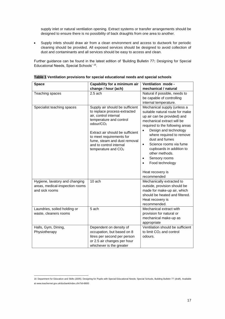
guidance and advice on ventilation should be adopted. The minimum requirements for ventilation
for hygiene and air quality should be as stated in Building Bulletin 77: Accommodation for special
educational needs and in special schools 14. These are summarised in Table 1 below.
Guidance for accommodating pupils with special educational needs and disabilities in mainstream
schools is specified in ‘Building Bulletin 94: Inclusive School Design: Accommodating Pupils with
Special Educational Needs and Disabilities in Mainstream Schools’ 15. Ventilation systems should
be controllable and adjustable, according to the needs of individual pupils. Air conditioning should
be avoided but where present should be regularly maintained to minimise noise emissions.
2.7.1 Cross-infection
Children in special schools may be vulnerable to infection, therefore, it is essential that infection-
control policies should be in place and implemented. Managing cross-infection is a complex
subject, but the risks of cross-contamination can be reduced through adequate source control and
by taking the measures below:
Hygiene areas, toilets, shower areas, cleaner’s rooms, areas holding soiled clothes or clinical
waste and laundry should be mechanically ventilated and slightly negatively pressurised
relative to adjacent spaces. This also assists odour control.
Recirculation of air, within areas occupied by pupils, by ventilation, air conditioning or heating
systems should be avoided as this will increase the risk of cross-infection and circulation of
allergens. Similarly, extract outlets should be positioned to avoid risk of recirculation into a
14 Department for Education and Employment (1992). Designing for Pupils with Special Educational Needs: Special Schools, Building Bulletin 77.
London: The Stationery Office. ISBN 0112707963.
15 Department for Education and Skills (2001). Inclusive school design: Accommodating Pupils with Special Educational Needs and Disabilities in
Mainstream schools, Building Bulletin 94., London: The Stationery Office. ISBN 011271109X.
17
supply inlet or natural ventilation opening. Extract systems or transfer arrangements should be
designed to ensure there is no possibility of back draughts from one area to another.
Supply inlets should draw air from a clean environment and access to ductwork for periodic
cleaning should be provided. All exposed services should be designed to avoid collection of
dust and contaminants and all services should be easy to access and clean.
Further guidance can be found in the latest edition of ‘Building Bulletin 77: Designing for Special
Educational Needs, Special Schools’ 16.
Table 1 Ventilation provisions for special educational needs and special schools
Space Capability for a minimum air
change / hour (ach)
Ventilation mode -
mechanical / natural
Teaching spaces 2.5 ach Natural if possible, needs to
be capable of controlling
internal temperature.
Specialist teaching spaces Supply air should be sufficient to replace process-extracted air, control internal temperature and control odour/CO2
Extract air should be sufficient to meet requirements for fume, steam and dust removal and to control internal temperature and CO2
Mechanical supply (unless a
suitable natural route for make
up air can be provided) and
mechanical extract will be
required to the following areas
Design and technology
where required to remove
dust and fumes
Science rooms via fume
cupboards in addition to
other methods.
Sensory rooms
Food technology
Heat recovery is
recommended
Hygiene, lavatory and changing
areas, medical-inspection rooms
and sick rooms
10 ach Mechanically extracted to
outside, provision should be
made for make-up air, which
should be heated and filtered.
Heat recovery is
recommended.
Laundries, soiled holding or
waste, cleaners rooms
5 ach Mechanical extract with
provision for natural or
mechanical make-up as
appropriate
Halls, Gym, Dining,
Physiotherapy
Dependent on density of
occupation, but based on 8
litres per second per person
or 2.5 air changes per hour
whichever is the greater
Ventilation should be sufficient
to limit CO2 and control
odours.
16 Department for Education and Skills (2005). Designing for Pupils with Special Educational Needs: Special Schools, Building Bulletin 77 (draft). Available
at www.teachernet.gov.uk/docbank/index.cfm?id=8693
18
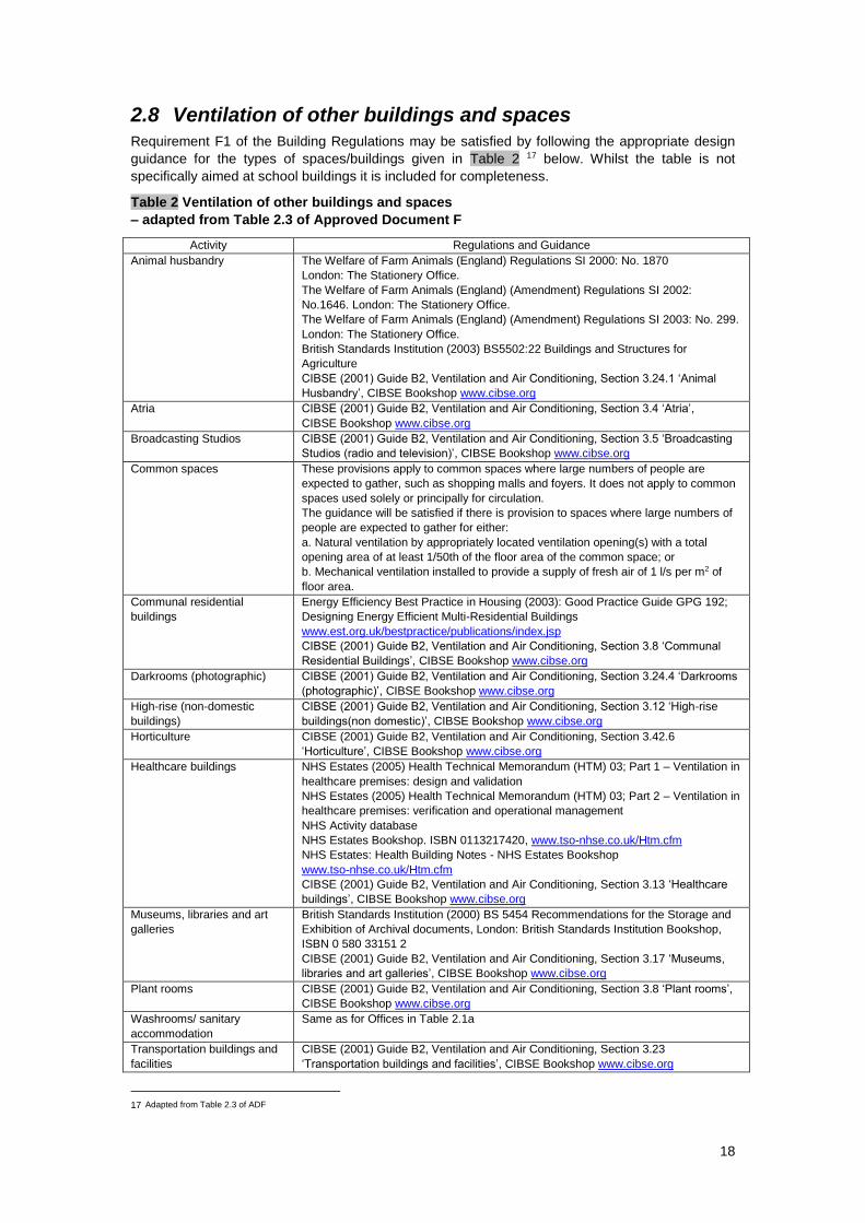
2.8 Ventilation of other buildings and spaces
Requirement F1 of the Building Regulations may be satisfied by following the appropriate design
guidance for the types of spaces/buildings given in Table 2 17 below. Whilst the table is not
specifically aimed at school buildings it is included for completeness.
Table 2 Ventilation of other buildings and spaces
– adapted from Table 2.3 of Approved Document F
Activity Regulations and Guidance
Animal husbandry The Welfare of Farm Animals (England) Regulations SI 2000: No. 1870
London: The Stationery Office.
The Welfare of Farm Animals (England) (Amendment) Regulations SI 2002:
No.1646. London: The Stationery Office.
The Welfare of Farm Animals (England) (Amendment) Regulations SI 2003: No. 299.
London: The Stationery Office.
British Standards Institution (2003) BS5502:22 Buildings and Structures for
Agriculture
CIBSE (2001) Guide B2, Ventilation and Air Conditioning, Section 3.24.1 ‘Animal
Husbandry’, CIBSE Bookshop www.cibse.org
Atria CIBSE (2001) Guide B2, Ventilation and Air Conditioning, Section 3.4 ‘Atria’,
CIBSE Bookshop www.cibse.org
Broadcasting Studios CIBSE (2001) Guide B2, Ventilation and Air Conditioning, Section 3.5 ‘Broadcasting
Studios (radio and television)’, CIBSE Bookshop www.cibse.org
Common spaces These provisions apply to common spaces where large numbers of people are
expected to gather, such as shopping malls and foyers. It does not apply to common
spaces used solely or principally for circulation.
The guidance will be satisfied if there is provision to spaces where large numbers of
people are expected to gather for either:
a. Natural ventilation by appropriately located ventilation opening(s) with a total
opening area of at least 1/50th of the floor area of the common space; or
b. Mechanical ventilation installed to provide a supply of fresh air of 1 l/s per m2 of
floor area.
Communal residential
buildings
Energy Efficiency Best Practice in Housing (2003): Good Practice Guide GPG 192;
Designing Energy Efficient Multi-Residential Buildings
www.est.org.uk/bestpractice/publications/index.jsp
CIBSE (2001) Guide B2, Ventilation and Air Conditioning, Section 3.8 ‘Communal
Residential Buildings’, CIBSE Bookshop www.cibse.org
Darkrooms (photographic) CIBSE (2001) Guide B2, Ventilation and Air Conditioning, Section 3.24.4 ‘Darkrooms
(photographic)’, CIBSE Bookshop www.cibse.org
High-rise (non-domestic
buildings)
CIBSE (2001) Guide B2, Ventilation and Air Conditioning, Section 3.12 ‘High-rise
buildings(non domestic)’, CIBSE Bookshop www.cibse.org
Horticulture CIBSE (2001) Guide B2, Ventilation and Air Conditioning, Section 3.42.6
‘Horticulture’, CIBSE Bookshop www.cibse.org
Healthcare buildings NHS Estates (2005) Health Technical Memorandum (HTM) 03; Part 1 – Ventilation in
healthcare premises: design and validation
NHS Estates (2005) Health Technical Memorandum (HTM) 03; Part 2 – Ventilation in
healthcare premises: verification and operational management
NHS Activity database
NHS Estates Bookshop. ISBN 0113217420, www.tso-nhse.co.uk/Htm.cfm
NHS Estates: Health Building Notes - NHS Estates Bookshop
www.tso-nhse.co.uk/Htm.cfm
CIBSE (2001) Guide B2, Ventilation and Air Conditioning, Section 3.13 ‘Healthcare
buildings’, CIBSE Bookshop www.cibse.org
Museums, libraries and art
galleries
British Standards Institution (2000) BS 5454 Recommendations for the Storage and
Exhibition of Archival documents, London: British Standards Institution Bookshop,
ISBN 0 580 33151 2
CIBSE (2001) Guide B2, Ventilation and Air Conditioning, Section 3.17 ‘Museums,
libraries and art galleries’, CIBSE Bookshop www.cibse.org
Plant rooms CIBSE (2001) Guide B2, Ventilation and Air Conditioning, Section 3.8 ‘Plant rooms’,
CIBSE Bookshop www.cibse.org
Washrooms/ sanitary
accommodation
Same as for Offices in Table 2.1a
Transportation buildings and
facilities
CIBSE (2001) Guide B2, Ventilation and Air Conditioning, Section 3.23
‘Transportation buildings and facilities’, CIBSE Bookshop www.cibse.org
17 Adapted from Table 2.3 of ADF
19
2.9 Historic school buildings
Designers involved in work on historic school buildings should recognise the need to conserve the
building’s special characteristics 18. Work should aim to improve ventilation to the extent that is
needed, and avoid prejudicing the character of the historic building or increasing the risk of long-
term deterioration to the building fabric or fittings. Advice from the local planning authority’s
conservation officer will help when deciding on the most appropriate balance between historic-
building conservation and ventilation.
Designers undertaking sensitive work on historic buildings would benefit from advice on the
following issues:
Restoring the historic character of a building that has been subject to previous inappropriate
alteration, e.g. replacement windows, doors and roof-lights.
Rebuilding a former historic building (e.g. following a fire or filling in a gap site in a terrace).
Making provisions to enable the fabric to “breathe” to control moisture and potential long-term
decay problems: see SPAB Information Sheet No. 4: The need for old buildings to breathe 19.
Pressure testing can be used to establish if the fabric of the historic building is leakier than a
modern building.
Advice on the factors determining the character of historic buildings is set out in Planning Policy
Guidance 15: Planning and the historic environment (PPG15) 20.
2.10 Kitchens
Where flueless gas appliances such as cookers are installed, adequate ventilation is required to
safeguard against the possibility of incomplete combustion producing carbon monoxide. A
mechanical system may be needed to provide this.
Due to the high ventilation rates required in such spaces, pre-heating of the ventilation air should
be considered. Heat recovery can be cost effective when a balanced mechanical ventilation
system is used The HVCA have published DW/171 which is a guide to kitchen ventilation and can
be used to help with these issues.21
Detailed advice on gas installations can be found in the publication Gas Installations for
Educational Establishments UP11 22.
The provision of carbon monoxide or oxygen detectors should be considered to warn occupants of
dangerous incomplete combustion which can occur if the ventilation is insufficient for combustion,
18 British Standards Institution (1998) BS7913 Guide to the Principles of the Conservation of Historic Buildings.
London: British Standards Institution Bookshop, ISBN 0 580 29515 X
19 Society for the Protection of Ancient Buildings (SPAB) (1987) Information Sheet 4, Need for Old Buildings to Breathe
London: SPAB Bookshop - www.spab.org.uk/publications.html
20 Office of the Deputy Prime Minister. Planning Policy Guidance 15: Planning and the historic environment. - www.odpm.gov.uk PPG15
21 HVCA: Standard for Kitchen Ventilation Systems DW/171.
22 Institute of Gas Engineers and Managers (2004) UP11: Gas Installations for Educational Establishments. -
www.igem.org.uk/Publications_Information.html.
20
or if the cookers are badly maintained. Guidance on air supplies required to support combustion
where cookers are installed is available in BS6173:2001 23.
Adequate combustion air, as required by BS6173:2001, means that ventilation controls may need
to be interlocked with gas supplies, e.g. on kitchen extract systems, unless an alternative means of
reducing risk to a practicable level can be demonstrated by other suitable methods of working.
Also in some situations, fire alarm systems must be linked to extract fans to shut down in the event
of a fire. Specialist advice on these matters will be required from a suitably qualified engineer.
Where gas cooking appliances are used, the ventilation may be regarded as a “power operated
flue” as described in the Gas Safety Regulations 24, and may need to be interlocked with the gas
supply as required by BS 6173 25. This type of ventilation may need to be provided at source, by
means of Local Exhaust Ventilation, in accordance with COSHH requirements. The HSE guidance
note on ventilation of kitchens in catering establishments gives good advice, some of which is
applicable to food technology rooms as well as school kitchens 26.
2.11 Dining Areas
The smell of food from dining areas can be a nuisance and therefore it is imperative to avoid the
transfer of these smells from these areas to the body of the school. This can be a particular
problem when atria contain food areas and are linked to large areas of the school.
23 British Standards Institution (2001) BS6173 Specification for the Installation of gas-fired catering appliances for use in all types of catering establishments
(2nd and 3rd family gases), London: British Standards Institution Bookshop, ISBN 0 580 33275 6
24 Health and Safety Executive (1998) L56 Safety in the installation and use of gas systems and appliances - Gas Safety (Installation and Use) Regulations
London: HSE Books. ISBN O 7176 1635 5
25 British Standards Institution (2001) BS6173 Specification for the Installation of gas-fired catering appliances for use in all types of catering establishments
(2nd and 3rd family gases)., London: British Standards Institution Bookshop, ISBN 0 580 33275 6
26 Health and Safety Executive (2000), Catering Information Sheet No 10 - www.hse.gov.uk/pubns/cais10.pdf
21
3 Indoor air quality and ventilation People typically spend 90% of their time indoors. Concern over human exposure to the pollutants
found indoors, and their potentially adverse effects on the health, productivity, comfort and well-
being of occupants, is therefore growing. In busy urban areas, the overall exposure levels inside a
building are likely to result from pollutants generated within and outside the building. Achieving
good indoor air quality in schools, therefore, depends on minimising the impact of indoor sources,
as well as reducing pollutant ingress by effective design of the building and operation of the
ventilation system.
3.1 Indoor air pollutants and their sources
Pollutants emitted indoors originate from occupants and their activities, and also from the building,
itself and from cleaning materials and furnishings. The major indoor pollutants and their sources
include:
Carbon dioxide (CO2) – CO2 is a product of human respiration and combustion. Exhaled air is
usually the principal source of CO2 in schools. CO2 levels inside classrooms are affected by a
number of factors including:
the number of occupants in the room;
the activity levels of occupants;
the amount of time occupants spend in the room; and
the ventilation rate.
A monitoring study in one school showed that, typically, CO2 levels in classrooms rose from the
start of each day, peaked before lunch time at 12.30pm, and then decreased over the lunch period
when the classroom was empty. After lunch, when the classroom was again occupied, CO2 levels
rose to a peak at the end of the school day at 3.30pm 27. CO2 levels from combustion may be
particularly high in food preparation areas and in science labs when Bunsen Burners are in use.
Odour – Odour is an indicator of poor air quality. It is emitted from people and from various
materials that may be found in school buildings. In general teaching classrooms, the internal air
quality in schools is determined largely by odour and CO2 levels, rather than by other pollutants.
Historically the level of fresh air provided to a classroom was specified to avoid significant odour as
perceived by persons entering the room. Occupants already in the room will not be aware of odour,
as the olfactory sense rapidly adjusts to an odour 28. Odours can therefore build up to unpleasant
levels and a sufficient fresh-air supply is needed to dilute and remove them.
Volatile organic compounds (VOCs) – VOCs are emitted from a wide range of products
including: building materials and furnishings (for example, surface finishes and paints); cleaning
products; and also from markers, glues and paints used in art classes. Common VOCs in schools
include:
formaldehyde;
decane;
butoxyethanol;
isopentane;
limonene;
styrene;
xylenes;
percholoethylene;
27 Kukadia V., Ajiboye P. and White M. (2005). Ventilation and Indoor Air Quality (IAQ) in Schools. BRE Information Paper
BRE Bookshop.
28 Fanger P. O. (1988). Introduction of the olf and the decipol units to quantify air pollution perceived by humans indoors and outdoors.
Energy and Buildings, No. 12, 1988.
22
methylene chloride;
toluene; and
vinyl chloride 29.
Some VOCs are known to be toxic and can adversely affect children in vulnerable groups (for
example, those that suffer asthma and allergies). There are also suggested links between VOC
levels and behavioural problems in children. At the levels found in school buildings, however, their
most likely health effect is short-term irritation of the eyes, nose, skin and respiratory tract. Odour
generated by VOCs is usually of more concern to the occupants. Formaldehyde is a particularly
strong smelling VOC. Although formaldehyde is carcinogenic, the concentrations in buildings do
not represent a significant risk. Approved Document F 30 suggests that concentrations of 0.1 mg/m3
may cause throat and nose irritation.
Moisture/humidity – Moisture is generated through occupant activities, for example cooking. High
humidity in spaces such as kitchens, bathrooms, gym areas and changing rooms can lead to
moisture condensing on cold surfaces resulting in fabric decay and mould growth. Airborne fungi
and dust mites can also be a problem. Dust mites, in particular, prefer moist warm conditions for
survival and their droppings are known to cause allergic reactions in some people.
Ozone – Ozone is emitted from office equipment such as photocopiers and laser printers and has
been known to cause respiratory problems. This type of office equipment is usually fitted with
carbon filters to minimise emissions. However, without an effective maintenance regime, ozone
concentrations can rise to unacceptably high levels.
Carbon monoxide (CO) – CO is a product of incomplete combustion and is generated from, for
example, gas cookers, gas water heaters and smoking. It is odourless, colourless and tasteless
and is potentially fatal at relatively low concentrations.
Particulate matter – Typical indoor particles include smoke particles, spores, biological fragments
and fibres. Some of these particles are known to be hazardous to health, for example, fibres from
MDF and bacteria. Normal control measures which apply in schools, such as the COSHH
procedures, should limit the risks to an acceptable level. The health implications of smaller
airborne particles, such as Polycyclic Aromatic Hydrocarbons from motor vehicles and particles
from diesel exhaust fumes, are not yet fully resolved, but they are unlikely to present a problem in
school buildings unless there are high levels of external pollution.
Asbestos - Asbestos and asbestos-containing materials (ACMs) are commonly found in schools
built or refurbished before 1985. However, some asbestos-containing materials continued to be
used up until 1999. If the material is disturbed or becomes damaged, asbestos fibres may be
released into the air and could present a risk if inhaled. Some damaged asbestos can be made
safe by repairing it and sealing or enclosing it to prevent further damage. Where asbestos cannot
be easily repaired and protected, it should be removed by someone who is trained and competent
to carry out the task. HSE guidance can help duty holders choose appropriate contractors to carry
out this work.
Further information on asbestos in school buildings can be found in the Asbestos Regulations 31 and HSE guidance 32.
29 Air Quality Sciences (date) New Asthma Studies Links VOCs and Allergens to an Increase in Childhood Asthma
www.aerias.org/uploads/Linking%20IAQ%20and%20Asthma%20in%20Schools.pdf 30 Department of the Environment and the Welsh Office. The Building Regulations 1991, Approved Document F1: Means of ventilation (1995 edition).
London, HMSO. Under revision.
31 Statutory Instruments: 1983/1649. Asbestos Licensing Regulations
London: The Stationery Office. ISBN: 0 11 037649 8
Statutory Instruments: 1999/2977. Asbestos (prohibitions) (amendments) (no. 2) Regulations
London: The Stationery Office. ISBN: 0 11 085450 0
32 Health and Safety Executive (2000), Asbestos - An Important Message For Schools
www.hse.gov.uk/asbestos/schools.pdf
23
Environmental tobacco smoke (ETS) – Smoking affects both those who smoke actively and
those exposed to the products of other people’s tobacco smoking and the air exhaled from their
lungs (passive smoking). ETS is a known carcinogen and poses a serious health risk to children,
particularly those suffering from asthma.
3.1.1 Minimising indoor pollutants
A number of methods are available for indoor air pollutant control. These are outlined below:
Emission control
Potentially harmful emissions from can be reduced by avoiding sources of pollutants; for example,
careful selection of materials can minimise VOC emissions. This may allow ventilation rates to be
lowered, thus providing a potential saving in energy use. Emission control is not considered within
the main guidance of Approved Document F, due to limited knowledge about the emission of
pollutants from construction and consumer products used in buildings, and the lack of suitable
labelling schemes for England and Wales 33. Some construction products such as glass, stone and
ceramics have low emissions. Some paints are now labelled for their VOC content, and some
wood-based boards are available with low formaldehyde emission 34. Labelling allows suitable
products to be chosen in ensuring good indoor air quality, but it is not currently practical to make
an allowance for use of these products in the ventilation requirements. However, work is continuing
in this area for inclusion in future revisions of Approved Document F. Further information about
control of emissions from construction products is available in BRE Digest 464 35, and information
on source control to minimise dust mite allergens is available in BRE Report BR 417 36.
Discouraging tobacco smoking
Discouraging tobacco smoking is another means of emission control by which harmful emissions
of carbon monoxide and smoke particles can be reduced. It is recommended that smoking be
banned in school buildings (Report of the Scientific Committee on Tobacco and Health, 1998) 37.
However, if the school management chooses to provide a room specifically for the use of smoking
members of staff, non-smoking staff members and children outside the room must be protected
from passive smoking. The ventilation requirement for the smoking room can be met by ensuring:
an air-extract rate of 36 l/s per person directly to the outside; and
an appropriate supply of make-up air which is designed to maintain a slightly lower
pressure (at least 5 Pa) inside the smoking room than in adjoining parts of the building.
It is essential that the ventilation system is operated correctly, and is well maintained. In addition,
the smoking room should be located such that children never need to enter it, and any door to the
smoking room should have an automatic closer. These provisions will not protect the health of
those using the room, and may not be sufficient to protect the health of those outside the room, but
should be sufficient to control odours. If the designated smoking areas are outside, these should
be located away from doors, windows and ventilation inlets.
It is recommended that designers consult current guidance on passive smoking at work issued by
the Health and Safety Executive (HSE). This guidance is designed to help employers meet their
responsibilities under Section 2(1) of the Health and Safety at Work Act 1974 38, to protect the
33 In Denmark, for example, the Danish Indoor Climate Labelling Scheme (DICL) assesses the impact of building materials and products on the indoor
environment. The scheme covers testing, emissions and decay rates for 10 product areas including interior paints, furniture and carpets. More information
can be found at www.danishtechnology.dk/building/13268
34 BS EN 13986: 2002 Wood-based panels for use in construction – Characteristics, evaluation of conformity and marking.
London. BSI Bookshop: ISBN 0 580 37500 5
35 BRE Digest 464: VOC Emissions from Building Products Parts 1 and 2; IP 12/03 VOC Emissions from Flooring Adhesives.
36 Raw G. J., Aizlewood C. E. and Hamilton R. M. (2001) Building Regulation, Health and Safety. BRE Report 417. BRE bookshop: www.brebookshop.com/ 37 Department of Health (1998) Report of the Scientific Committee on Tobacco and Health
www.archive.official-documents.co.uk/document/doh/tobacco/contents.htm
38 Health and Safety at Work Act (1974)
24
health, safety and welfare of their employees. HSE booklet Passive Smoking at Work 39 offers
advice to employers on ways to reduce the exposure of their employees to tobacco smoke. The
best approach to adopt depends on what is reasonably practicable in a particular workplace, in this
case, a school. Local Authority Circular 91/1 40 also gives advice to local authority enforcement
officers on how to enforce the requirements of the 1974 Act in the context of passive smoking in
the workplace.
3.2 Related performance-based standards
Approved Document F does not provide performance-based guidance for schools. However, it
does recommend performance levels for office-type accommodation.
The average relative humidity in a room should not exceed 70% for more than two hours in
any 12-hour period during the heating season.
Nitrogen dioxide (NO2) levels should not exceed 288 g/m3 (150 ppb) averaged over one
hour. 41
Carbon monoxide should not exceed
o 100 mg/m3 (90 ppm) – 15-minute averaging time
o 60 mg/m3 (50 ppm) – 30-minute averaging time
o 30 mg/m3 (25 ppm) – 1-hour averaging time
o 10 mg/m3 (10 ppm) – 8-hour averaging time
Total volatile organic compound (TVOC) levels should not exceed 300 g/m3 averaged over
eight hours.
Ozone levels should not exceed 100 g/m3.
In most cases, it would be expected that the pollutant emissions in teaching or learning areas
would be similar to those in office-type accommodation. Thus given the higher ventilation rates in
schools compared to offices, this guidance should be met. However, there will be some school-
specific activities where further consideration is necessary e.g. the use of art materials (e.g. paints)
which can result in a high TVOC level.
3.3 Outdoor air pollutants and sources
A wide range of pollutants generated outdoors are either known or suspected of adversely
affecting human health and the environment. Key urban pollutants that need to be considered
include those covered by the UK National Air Quality Strategy (NAQS) (DETR, 2000) 42. These
are:
Carbon monoxide, CO;
Nitrogen dioxide, NO2;
Sulphur dioxide, SO2;
Ozone, O3;
Particulate matter, PM10;
Benzene;
1,3-Butadiene;
Lead.
39 Health and Safety Executive (1993), Passive smoking at work IND(G)63(L) (Revised), HSE Books - www.hsebooks.com/Books
40 HSE (2000) Local Authority Circular LAC 91/1 - www.hse.gov.uk/lau/lacs/91-1.htm
41 Department of Health, Committee on the Medical Effects of Air Pollutants (2004) Guidance on the Effects of Health of Indoor Air Pollutants
www.advisorybodies.doh.gov.uk/comeap/PDFS/guidanceindoorairqualitydec04.pdf 42 Department of the Environment, Transport and the Regions, The Scottish Executive, the National Assembly for Wales and the Department of the
Environment for Northern Ireland (2000). The Air Quality Strategy for England, Scotland, Wales and Northern Ireland. London: The Stationery Office ISBN 0
101454 82 1.
25
Although nitrogen oxide, NO, is not included in the NAQS, it is a normal constituent of combustion
discharges, and in many cases is the largest polluting emitter. This is especially the case for gas-
fired plant. NO is readily oxidised to NO2 so both these gases need consideration.
Sources of outdoor pollutants include:
transport. This includes traffic junctions and car parks (underground car parks in
particular), and traffic-generating developments. In urban areas, emissions and noise from
road-transport sources can adversely affect the indoor environment;
air traffic can result in emissions and noise, particularly near large airports such as
London Heathrow
combined heat and power plant (CHP);
other combustion processes (for example, waste incinerators and boilers);
discharges from industrial processes. Industrial emissions include a wide range of
substances such as lead, VOCs, smoke, ozone and oxides of nitrogen and sulphur;
fugitive (i.e. adventitious / not effectively controlled) discharges from industrial processes
and other sources;
building-ventilation-system exhaust discharges and fume cupboards or other local exhaust
ventilation discharges;
construction and demolition sites. These are sources of particles and vaporous
discharges;
agricultural processes. In intensively farmed areas, bacteria, pollen, fungi and odours can
be a problem, as can fertilisers and insecticides;
soil-borne pollutants. These include methane and radon. They can enter the building via
cracks or penetrations in the foundations or other parts of the building envelope.
3.3.1 Minimising ingress of polluted outdoor air into buildings
In urban areas, buildings are exposed simultaneously to a large number of individual pollution
sources from varying upwind distances and heights, and also over different timescales. The
relationship between these and their proportionate contribution under different circumstances
governs pollutant concentrations over the building shell and the degree of internal contamination.
Internal contamination of buildings from outdoor pollution sources therefore depends upon:
the pollutant dispersion processes around the buildings;
the concentrations of pollutants at the air inlets;
the ventilation strategy (natural, mixed-mode, mechanical);
pollution depletion mechanisms;
the airtightness of the building (i.e. the ability of the building envelope to prevent the
uncontrolled ingress of pollutants).
Further information can be found in Kukadia and Hall (2004) 43.
Ventilation air intake location
It is important to ensure that the intake air is not contaminated regardless of the type of ventilation
system in operation. This is especially important in Air Quality Management Areas 44 where, by
definition, pollution levels of at least one pollutant have exceeded the Air Quality Standards 45. The
siting of exhausts and fume cupboard discharge stacks is also important – this is discussed below.
Guidance on ventilation intake placement for minimising ingress of pollutants is summarised in
Table 3 (reproduced from Approved Document F). The guidance given in Table 3 is greatly
43 Kukadia V. and Hall D. J. (2004). Improving Air Quality in Urban Environments: Guidance for the Construction Industry. BR 474, Building Research
Establishment. ISBN 1 86081 729 7
44 For Air Quality Management Areas see: www.airquality.co.uk/archive/laqm/laqm.php
45 Air Quality Management (2002). Air Quality Strategy Wallchart – Summary of Proposed Objectives in the Latest Consultation, November 2002. Gee
Publishing.
26
simplified and cannot be applied to all sites. The risks associated with specific sites may need to
be assessed either through guidance from an expert or by physical modelling.
Control of ventilation intakes
The concentration of pollutants from sources such as urban road traffic, fluctuate with the time of
day. In such cases, reducing the flow of external air or closing ventilation intakes for up to an hour
during periods of high external pollutant concentrations may be an option. Automated control using
time controls and a sensor for the relevant pollutant will probably be required. Closing air inlets
during rush hour may also be desirable to prevent the ingress of noise as well as traffic fumes.
Air intakes located on a less polluted side of the building may then be used for fresh air, or air may
be fully re-circulated within the building. Alternatively, the building may be used as a ‘fresh air’
reservoir to supply air during these short periods. The use of atria as a source of ‘fresh air’ for this
purpose may be an option, but noise transfer and food smells through the atria can make this
difficult. Schools tend to have an advantage over other buildings, as classrooms tend to have fairly
high ceilings. In modern schools, corridors tend to be used as resource areas, so have large
volumes and there is usually an assembly hall and/or a gym.
However, care must be taken since, for example, reducing the inflow of external air will also reduce
the outflow of internal air resulting in a build-up of internally generated pollutants that need to be
removed. Some modern buildings have low ceiling heights and therefore the concept of a
substantial ‘fresh-air reservoir’ available within the building may not apply. For this reason, a
minimum floor-to-ceiling height of at least 3 m is desirable in a naturally ventilated classroom or
other teaching space. This is even more desirable in science labs, prep rooms and workshops,
where activities may result in higher pollutant emission. Further details of this principle with
examples may be found in: Liddament, M.W (2000) Indoor Air Quality Handbook, Chapter 13:
Ventilation Strategies, McGraw-Hill.
Location of exhaust outlets
The location of exhausts is as important as the location of air intakes. Exhausts should be located
to minimise re-entry to the building, for natural and mechanical intakes, and to avoid adverse
effects to the surrounding area. Guidance on outlet placement is summarised as follows:
Exhausts should be located downstream of intakes where there is a prevailing wind
direction.
Exhausts should not discharge into courtyards, enclosures or architectural screens as
pollutants do not disperse very readily in such spaces.
It is recommended that stacks should discharge vertically upwards and at high level to
clear surrounding buildings, and so that downwash does not occur.
Where possible, pollutants from stacks should be grouped together and discharged vertically
upwards. The increased volume will provide greater momentum and increased plume height. This
is common practice where there are a number of fume cupboard discharges; greater plume-height
dispersion can be achieved by adding the general ventilation exhaust.
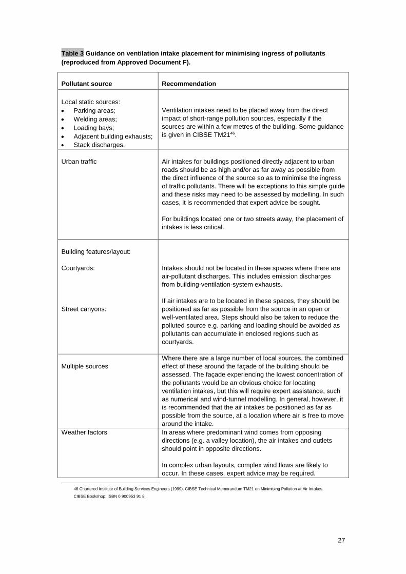
27
Table 3 Guidance on ventilation intake placement for minimising ingress of pollutants
(reproduced from Approved Document F).
Pollutant source
Recommendation
Local static sources:
Parking areas;
Welding areas;
Loading bays;
Adjacent building exhausts;
Stack discharges.
Ventilation intakes need to be placed away from the direct
impact of short-range pollution sources, especially if the
sources are within a few metres of the building. Some guidance
is given in CIBSE TM2146.
Urban traffic
Air intakes for buildings positioned directly adjacent to urban
roads should be as high and/or as far away as possible from
the direct influence of the source so as to minimise the ingress
of traffic pollutants. There will be exceptions to this simple guide
and these risks may need to be assessed by modelling. In such
cases, it is recommended that expert advice be sought.
For buildings located one or two streets away, the placement of
intakes is less critical.
Building features/layout:
Courtyards:
Street canyons:
Intakes should not be located in these spaces where there are
air-pollutant discharges. This includes emission discharges
from building-ventilation-system exhausts.
If air intakes are to be located in these spaces, they should be
positioned as far as possible from the source in an open or
well-ventilated area. Steps should also be taken to reduce the
polluted source e.g. parking and loading should be avoided as
pollutants can accumulate in enclosed regions such as
courtyards.
Multiple sources
Where there are a large number of local sources, the combined
effect of these around the façade of the building should be
assessed. The façade experiencing the lowest concentration of
the pollutants would be an obvious choice for locating
ventilation intakes, but this will require expert assistance, such
as numerical and wind-tunnel modelling. In general, however, it
is recommended that the air intakes be positioned as far as
possible from the source, at a location where air is free to move
around the intake.
Weather factors In areas where predominant wind comes from opposing
directions (e.g. a valley location), the air intakes and outlets
should point in opposite directions.
In complex urban layouts, complex wind flows are likely to
occur. In these cases, expert advice may be required.
46 Chartered Institute of Building Services Engineers (1999). CIBSE Technical Memorandum TM21 on Minimising Pollution at Air Intakes.
CIBSE Bookshop: ISBN 0 900953 91 8.
28
Filtration
Filtration provides a means of cleaning the intake air. It is standard practice to fit filters to
mechanical ventilation systems. Mechanical systems can, because of this, be perceived as
providing cleaner air to the space. However, it must be noted that filtration systems are only
effective at dealing with the pollutants they are designed for. Mechanical ventilation system air-
intake filters are primarily used for particle removal. Activated carbon filters are required if it is
necessary to remove gaseous pollutants. As these are exceptionally demanding and costly it is
preferable to avoid the need for removal of gaseous pollutants from outside air by effective
positioning of intakes.
Building ‘airtightness’
An airtight building envelope will prevent the uncontrolled ingress of contaminated outdoor air. The
implications of ‘airtightness’ for building energy use, rather than ingress of air, are addressed in
Approved Document L of the Building Regulations (2006).
This specifies minimum performance requirements in terms of air permeability. Air permeability is
defined as the air leakage in m3h-1 per metre square (m3h-1m-2) of building envelope area, which
includes the ground-supported floor area, at a reference pressure of 50 Pa. The maximum
permitted value specified by Part L is 10 m3h1m-2. All buildings over 1000 m2 gross floor area must
be tested to meet this criterion. Full details on achieving and verifying performance are given in the
ATTMA publication ‘Air Permeability Measurement’ 47.
Construction and retrofit, to at least the current Regulations, should be regarded as essential to
prevent the uncontrolled ingress of pollutants.
47 Air Permeability Measurement, Air tightness Testing and Measurement Association (ATTMA),.
29
4 Ventilation strategies
4.1 Ventilation system
Traditionally, schools have been designed for natural ventilation and good daylighting. This
resulted in narrow-plan schools provided with large areas of openable windows, often offering
cross ventilation combined with stack ventilation by clerestory windows. Studies have shown that
this can provide the required level of fresh air. However, classroom occupants are typically not
able to exploit the full potential of the ventilation and accept a slightly reduced level of air quality
because of problems of operation or draughts.
Modern schools will generally be much more air tight than previously and it is critical that users
have control of the ventilation and understand how to use it: guidance should be provided in the
building log-book and handover information (see section 7).
The current trend towards maximising use of the available floor area through design of deep plan
spaces and the increased use of ICT has led to concerns about overheating in classrooms. This
has renewed interest in natural and mechanical ventilation systems that will perform better than the
simple window-opening approach of previous school designs, and incorporate passive cooling.
4.1.1 Natural ventilation
Purpose-designed natural ventilation, as opposed to simple window-opening strategies, can
provide the following advantages:
lower running costs through lower energy consumption;
decreased capital costs;
decreased maintenance costs;
reduced energy use by fans to transport the air;
fewer problems from plant noise;
sound insulation of the building envelope, reducing the ingress of traffic noise.
Naturally ventilated buildings are cheaper to construct than equivalent mechanically ventilated
buildings; as a rule of thumb they cost 10% - 15% less to construct. A significant reduction in the
cost of the engineering services usually more than compensates for some extra costs in envelope
improvements, such as external shading and openable windows, or sound attenuated ventilation
openings. Smaller plant also requires less plant room space.
Naturally ventilated buildings have no HVAC systems, and as a consequence can achieve low
energy consumption. Fan energy is avoided, as air movement is achieved through well-designed
opening windows, other ventilation openings, or more sophisticated ventilation stacks and flues,
which make use of wind and buoyancy effects. This results in significantly lower operating and
maintenance costs.
However, for all of these benefits to be realised, care must be taken to design the natural
ventilation system correctly. This will entail giving consideration to the size and location of
openings; ClassVent 48 is a simple tool that will greatly assist in the design process. To increase
occupant satisfaction, the ventilation system must be controllable, and integrated in such a way
that draughts are avoided.
4.1.2 Hybrid ventilation
A potentially more environmentally and financially sound solution than adopting a full mechanical
ventilation system is to adopt a ‘hybrid’ or mixed mode ventilation strategy. The underlying
principle of a hybrid system is that the school is designed as a naturally ventilated building –
48 DfES (2006) ClassVent - www.teachernet.gov.uk/iaq
30
without ductwork for air transport – but provision is made to assist the airflow through the space
when natural driving forces are inadequate. To ensure that the airflow is not restricted, care must
be taken with partitioning and the use of down-stand beams that may interrupt the airflow and its
contact with exposed soffits.
Hybrid ventilation can therefore lower the capital costs of the ventilation system by reducing
ductwork and the space required for plant rooms. It can also lessen the running costs for cleaning
and maintenance compared to a full mechanical ventilation system.
In this form hybrid ventilation can also be better suited to using the thermal mass of the building
fabric than a full mechanical system where suspended ceilings used to hide ductwork, may reduce
the potential for contact of the air with the thermal mass. Controlling the hybrid system to provide
night cooling may also be easier than a natural ventilation only solution because a single extract
point can be provided for a large area of the school and the increased pressure drops provided by
the fan.
The concern that changing practice in the use of schools or changes in climate may require the
adoption of mechanical ventilation, is addressed in CIBSE’s Applications Manual 13 49. This
provides a very detailed description of mixed-mode and hybrid ventilation, and should be consulted
before a full mechanical ventilation system is installed.
4.1.3 Mechanical ventilation
Mechanical systems are expensive but may offer an advantage in energy terms as they do allow
the option of providing heat recovery. However, in schools this is less attractive than may be
thought because for most of the occupied period the internal gains are high and will provide most
of the heating load. Heat recovery is then less valuable. Therefore, although heat recovery
improves the energy efficiency of mechanical ventilation systems it will rarely be cost effective in a
school.
Currently no suitable technology for heat recovery exists in natural ventilation designs. This may
lead to mechanical ventilation being economically attractive in special cases such as ICT rooms.
However, mechanical ventilation alone will not remove large quantities of internal heat gains in the
summer, when they are most problematic, because of the limited extent to which the air can
transport the excess heat.
Comfort cooling, with all the associated costs, then becomes necessary. If mechanical ventilation
is being considered a whole-life-cost calculation should be carried out as part of the option
appraisal including: initial capital and installation costs; maintenance and replacement costs;
operational electricity costs and, where heat recovery is included, the cost of gas for space heating
or DHW.
Both mechanical and hybrid ventilation systems lend themselves to control by a BMS or other
similar system. Hence, mechanical ventilation may be controlled directly by level of CO2 measured
in the space or in response to sensing of the occupancy of the space. If associated variable speed
control fans are used then the ventilation rate supplied and the fan energy used can more closely
match the demand profile.
4.1.4 Local ventilation
Local extraction is required from processes or rooms where water vapour and/or pollutants are
released through activities such as showering, cooking or chemical experiments. This is to
minimise their spread to the rest of the building. The exhaust ventilation may be either intermittent
or continuous – (see Table 1.1a Approved Document F). Provision should be made to protect the
fresh-air supplies from contaminants hazardous to health.
49 CIBSE (2000). Mixed Mode Ventilation, Applications Manual AM13, CIBSE Bookshop: ISBN 1 903287 01 4
31
Local extract to outside is required in all sanitary accommodation, washrooms and food and
beverage preparation areas. In addition, printers and photocopiers used frequently or continuously,
should be isolated (to avoid any pollutants entering the occupied space) and local extract provision
installed. This also includes fume cupboards and local exhaust-hood-type vent systems that
remove pollutants at source. The recommended minimum extract flow rates are given in Table 4.
Photocopiers have active carbon filters which, if well maintained, will limit ozone emissions.
Information about the maintenance of photocopiers can be found in Local Authority Circular: LAC
90/2 50.
Table 4 Ventilation rates for local extract 51
Room Local extract
Rooms containing printers and
photocopiers in substantial use (greater
than 30 minutes per hour)
Air-extract rate of 20 l/s per machine during use.
Note that if operators are continuously in the room, use
greater extract and whole-building ventilation rates
Sanitary accommodation and
washrooms.
Intermittent air-extract rate of the lesser of:
6 ach 52 or;
15 l/s per shower/bath or;
6 l/s per WC.
Food and beverage preparation areas
(not commercial kitchens); including
food-technology areas.
Intermittent air-extract rate of:
15 l/s with microwave and beverages only;
30 l/s adjacent to the hob with cooker(s);
60 l/s elsewhere with cooker(s).
All to operate while food and beverages preparation is
in progress.
Specialist rooms (e.g. commercial
kitchens, fitness rooms)
See Table 2.3 of Approved Document F
4.2 Ventilation and heating
The energy required to condition the outdoor air in winter can be a significant portion of the total
space-conditioning load, and increasingly so as fabric insulation increases. Air exchange typically
represents 20% to 50% of a building's thermal load, and this is one reason to limit air-exchange
rates in schools to the minimum required. An energy-efficient design aims to provide thermal
comfort and acceptable indoor air quality with the minimum use of energy. In winter, any fresh air
above that required for controlling indoor air quality represents an energy penalty. This means that
careful thought needs to be given to the detailed design of the ventilation system.
Natural ventilation can contribute to a sustainable environment by reducing the electrical energy
used in buildings. Most naturally ventilated buildings are narrow plan, and this can allow increased
utilisation of daylight, thereby reducing demand for electric lighting in addition to the reduced
energy demands of ventilation fans and air-handling plant. Mechanical ventilation is a primary
energy-intensive process and air conditioning is even more so.
The interaction between ventilation and the heating system should also be considered. For
example, the heating system should be sized to provide heat for the incoming fresh air based on
the lower heat load that corresponds to 3 l/s per person – not the capability of 8 l/s per person. In
50 HSE (2000) Local Authority Circular 90/2 - www.hse.gov.uk/lau/lacs/90-2.htm
51 Adapted from Table 2.1a of ADF 52 This a specified in the School Premises Regulations - Requirement 21(3)
32
addition, when the school is occupied the internal heat gains often provide a large part of the
ventilation heat loss and most heating is pre-heat when fresh-air supply should be minimal.
If an area of the building gets too warm (e.g. by solar gain through a window), the instinctive
reaction of the occupant is likely to be to open the window rather than to turn down the heating.
The use of localised controls will minimise this potential conflict. More sophisticated techniques
include interlocks between the heating system and window opening.
4.3 Acoustics
There is a strong relationship between ventilation and acoustics, particularly with natural
ventilation. Natural ventilation systems generate no noise themselves, but do allow the ingress of
external noise, for example from traffic, into the building. A passage provided for the flow of
ventilation air – either internally or from the outside – also becomes a path for noise. The
standards of acoustic performance now required for schools, as determined by BB93 53 and the
Building Regulations, demand careful consideration of the interaction of the ventilation strategy
and the acoustic performance of the building. Experience has shown that some good natural
ventilation strategies have not worked in practice, because of the transmission of unwanted sound.
4.3.1 External noise
Noise from road vehicles, rail and air traffic, is often cited as a major constraint on the use of
natural ventilation. For an external-free-field A-weighted noise level 54 dominated by road traffic,
facades with typical manually controlled open windows attenuate the noise into a classroom with
0.5 second reverberation time by between 8 dB and 14 dB. Therefore the external free-field noise
should not exceed 49 dBA for the indoor noise level to be below 35 dBA.
Automatically controlled windows, and other vents that allow close control of the open area, can
provide considerably better sound attenuation of up to 20 dBA - 30 dBA. If classrooms are located
on the noisy facades, normal manually opening windows might not be possible, but automatically
or other closely controlled windows, roof-mounted ventilators or sound-attenuated openings might
be an option55.
The noise from ventilator actuators can be a problem. This noise is intermittent and where
automatic systems are not under user control, relatively low noise levels can be very disruptive to
class activities. Therefore, it is essential that noise levels from these actuators are kept well below
the indoor ambient noise levels given in Table 1.1 of Building Bulletin 93.
Before adopting a natural ventilation strategy, the required indoor ambient noise levels in the
different spaces in the building and external noise levels will need to be established. It is usually
advisable to employ a noise specialist to do this and to look at possible options to attenuate the
external noise. In some cases, constant levels of road-traffic noise, for example from distant
arterial roads, may be desirable to mask noise from neighbouring activities. However, specialist
acoustic advice is needed where levels higher than those proposed in Section 1.5 are proposed.
Section 1.2.1 of BB93 permits the use of Alternative Performance Standards. These provide scope
for designers to increase the indoor ambient noise levels on a selective basis where, for
environmental, educational or health and safety reasons, it would be preferable to allow a higher
indoor ambient noise level.
53 Department for Education and Skills (date). Acoustic Design of Schools – a design guide, Building Bulletin 93. London: The Stationery Office. ISBN 0 11
271105 7 - www.teachernet.gov.uk/acoustics
54 Free field describes a sound field in which the effects of obstacles or boundaries on sound propagated in that field are negligible. A-weighted describes a
sound containing a wide range of frequencies in a manner representative of the ear's response, with the effects of the low and high frequencies reduced with
respect to the medium frequencies.
55 Sound Measurements and Natural Ventilation in Schools: Alice Andersen, Carl Hopkins. International Journal of Ventilation: Volume 4 No.1 June 2005
Edition
33
Generally it is possible to develop strategies to avoid or control external sources of noise and still
use natural or hybrid ventilation techniques. An increasing range of components providing airflow
and noise attenuation are available to control noise ingress from outside and sound transmission
between spaces. Reference to Building Bulletin 93 and suitable case studies is essential for a full
understanding of the issues58.
4.3.2 Internal noise
Since the introduction of BB93, some design teams have not used cross-ventilation between
classrooms and corridors, or between classrooms and atria, due to the difficulty in achieving the
required sound insulation between these spaces, when they are linked by a ventilator. In general,
ventilation paths across partitions significantly reduce the airborne sound insulation of that
partition, unless they use a ventilator that has been acoustically treated. However, the addition of
sound-absorbent material in a ventilator also reduces its efficiency as a ventilation path, and it can
sometimes be difficult to reconcile the demands for sound insulation and ventilation. Acoustically
attenuated ventilators can be used to satisfy normal loads, and be supplemented by boost fans for
periods requiring higher ventilation, such as intensive use of IT or summer overheating.
Research 56 into the sound attenuation and airflow characteristics of different configurations of a
prototype ventilator, intended for cross-flow ventilation in schools, shows that eight of the prototype
ventilator configurations that were tested had sufficiently high airborne sound insulation to satisfy
the BB93 performance standards. In addition, the airflow tests indicate that although the equivalent
areas are reduced due to the presence of sound absorptive material inside the ventilator, the
values are still sufficiently high to allow naturally driven cross ventilation using the stack effect of
an atrium57.
4.3.3 Mechanical ventilation noise
Mechanical ventilation systems are not silent, and the standards in BB93 are seen as challenging
even for full mechanical systems. Fans can generate noise that can travel easily through ductwork
to occupied spaces. To overcome this, designers can put noise attenuators either in the ductwork,
or as part of the ventilation plant, or specify quieter equipment. Attenuators in ductwork systems
add to the capital costs and increase pressure losses, which increases the fan power required.
Higher fan power results in greater energy use and therefore higher running costs. In addition,
ventilation plant and chillers that are manufactured to low noise levels are more expensive than
standard units, or will involve special acoustic enclosures that take more space and cost more.
The designer is advised to consider the noise produced by any proposed mechanical system early
in the design process as it may limit some design solutions. It should also be remembered that
mechanical systems should be capable of providing 8 l/s per person at all times and the indoor
ambient noise levels given in BB93 Table 1.1 should not be exceeded when the mechanical
ventilation system is operating at its maximum specified airflow rates.
4.4 Fire precautions
Note that Approved Document B 58 includes provisions for the size of escape windows. If the
openable area required for fire escape is larger than that required for ventilation, it should apply in
all cases.
56 BRE Client Report (2004): A prototype ventilator for cross ventilation in schools: Sound insulation and airflow measurements. Client report number
220497 - www.bre.co.uk/filelibrary/DfES_cross_ventilator_complete_report.pdf
57 M White, G McCann, R Stephen, M Chandler (1999) Ventilators: ventilation and acoustic effectiveness, IP 4/99. BRE Bookshop: ISBN 1860812643
58 ODPM Building Regulations (2002): Approved Documents B, Fire safety 2000 (consolidated with 2000 amendments and 2002 amendments).
London: The Stationery Office.
34
Fire precautions may be required to ensure that compartmentalisation and escape routes are not
prejudiced by the presence of passive stack ventilation ducts. Guidance on such fire precautions
may be found in Building Regulations: Approved Document B.
New government guidance on fire safety for schools is also being produced. ‘Building Bulletin 100:
Designing Against The Risk Of Fire In Schools’, will give guidance on the design of new schools as
well as the refurbishment of existing schools. 59
4.5 Interaction of mechanical extract ventilation and open-
flued combustion appliances
Extract fans can cause the spillage of combustion products from open-flued appliances by lowering
the pressure in a building. This can occur even if the appliance and the fan are in different rooms.
Ceiling sweep fans produce air currents and hence local depressurisation which can also cause
the spillage of flue gases from open-flued gas appliances or from solid-fuel open fires. In buildings
where it is intended to install open-flued combustion appliances and extract fans, the combustion
appliance should be able to operate safely whether or not the fans are running. In these
circumstances, compliance can be demonstrated by following the guidance given in Approved
Document J 60 on the installation of the appliances and conducting tests to show that combustion
appliances operate safely whether or not fans are running.
4.6 Access for maintenance
For all ventilation systems, reasonable provision should be made to maintain the components
including:
a. access to replace filters;
b. access points for cleaning ductwork;
c. access to replace, maintain and repair fans, heat exchanger and other HVAC
plant.
Adequate space should be provided in plant rooms for the maintenance of the plant. Approved
Document F recommends that where no special provision is required, 600mm space should be
provided where access is required between plant, and 1100mm where space for routine cleaning
is required (see Diagram 4 in Approved Document F). These are guidelines for the minimum space
needed and additional space may be needed for opening of access doors, withdrawal of filters,
etc.
Further guidance for more complex situations can be found in Defence Works Functional Standard, Design & Maintenance Guide 08: Space requirements for plant access operation and maintenance. 61
59 Department for Education and Skills (2000). Designing Against The Risk Of Fire In Schools, Building Bulletin 100
London: The Stationery Office. ISBN 0 11 271040 9 - www.teachernet.gov.uk/_doc/971/SBfire_safety_guide%5B1%5D.pdf
60 ODPM Building Regulations (2001): Approved Documents J, Combustion appliances and fuel storage systems (2002 edition).
London: The Stationery Office.
61 Ministry of Defence (1996) Space Requirements for Plant Access and Operation, Design and Maintenance Guide 08
London. The Stationery Office ISBN 0 11 772785 7
35
5 Designing for natural ventilation
5.1 Basic ventilation principles
The starting point in ventilation design is to determine how much ventilation air is required, and for
what purposes. For indoor air quality, as specified in section 1.4 of this Building Bulletin, the
requirement for ventilation of teaching and learning spaces is based on the capability to provide
each person with 8 l/s of fresh air. This design capability is needed at all times in winter and
summer. Often it is also necessary to design for the cooling effect of external air. To provide
adequate cooling during the daytime in summer this ventilation rate will most likely need to be
greater than 8l/s per person. Similarly, for night-time cooling of the thermal mass of the building
higher air flow rates may be required.
This section outlines the basic principles underlying natural ventilation, and explains how best to
proceed with a specific design. It is not intended to be a textbook of natural ventilation; the main
aim is to assist school designers to quickly establish how their school building may be naturally
ventilated.
The Department for Education and Skills has provided the ClassVent 62 calculator to be used with
Building Bulletin 101 that enables a designer to rapidly calculate areas for airflows into and out of a
classroom. Designs using the ClassVent calculator could be considered as satisfying the guidance
given in Section 1.4 of this Building Bulletin when used with the design conditions specified in
Section 5.4.2. Other design tools can also be used, but calculations for these designs would need
to be submitted for building control approval.
In addition to ClassVent, a complementary tool has also been provided, ClassCool, which provides
a simplified method of assessing the extent of classroom overheating. This is described in section
8.1. The common link between these tools is the ventilation rate. Typically, ventilation rates
required for achieving good indoor air quality are lower than those to limit the risk of overheating.
Therefore, when using these tools an element of ‘iteration’ may be required to achieve a design
that satisfies both heating season and non-heating season requirements.
The ClassVent tool is available from the Department’s website, together with reports outlining the
development of the ventilation requirements for schools and the testing of the ClassVent tool.
5.2 Natural ventilation driving forces
Natural ventilation is mainly driven by two mechanisms; the stack effect, and wind pressure (or the
‘wind effect’).
The stack effect arises from the decrease in the density of air as its temperature increases.
Generally, internal air will have a higher temperature and therefore a lower density than the cooler
outside air. If a boundary separates these two masses of air, a pressure difference will exist across
the boundary. At either ends of the boundary, or at openings in the boundary, air will flow across
the boundary from high to low pressure regions. Normally, this provides a flow of air into the lower
part of the building and out of the higher part of the building. The ventilation rate achieved through
the stack effect increases with the height of the boundary, or stack of air, as the overall pressure
difference will be greater.
The stack effect does not actually rely on a physical ‘stack’ or chimney. In a classroom that is
warmer than outside and has two separate openings in a wall, a pressure difference will exist
across the wall and cause air to flow into the lower opening and out of the upper opening.
62 DfES (2006) ClassVent - www.teachernet.gov.uk
36
As the temperature inside and outside the building becomes more equal (in summer for example)
the pressure drop across the openings, and hence the stack effect, decreases, reducing the
ventilation rate. To counter this effect the total openable area of the facade must be increased.
Wind pressure also influences the ventilation of a building by creating variations in pressure
around the outside of the building. Variations in pressure are highly dependent on the building form
and the wind speed and direction. Typically, an increase in pressure is experienced on the façade
facing the wind and a negative pressure is experienced on the other façades. However roofs can
be subject to either positive or negative pressures. These effects are dealt with by the use of
appropriate wind pressure coefficients that are included with most ventilation simulation
programmes.
Wind pressure coefficients are available for a wide range of simple, regular building forms and for
particular wind patterns. For more complex building designs, wind pressure coefficients may need
to be determined by experimentation in a wind tunnel.
The stack effect and wind effect can combine to increase the overall driving forces, but can also
oppose each other and result in no overall pressure difference, and therefore no ventilation airflow.
Even though the wind speed is typically greater than 3 metres per second (m/s) for most places in
the UK, and will often assist the stack effect, it is advisable to consider the performance for a still,
or relatively calm, day as this is the most challenging condition. At the early design stages it is
advised that simple strategies relying on the more predictable stack effect are adopted, particularly
if detailed information about wind-pressure coefficients and wind speed and direction is not
available.
Simple natural ventilation calculations are open to error as they are approximations based on the
bulk properties of the air. However, even detailed Computational Fluid Dynamics (CFD) models
used by a highly skilled modeller will not necessarily improve on the accuracy of simple empirical
equations. Therefore, the simple ClassVent model is likely to be a good starting point for proving
the adequacy of natural ventilation designs.
5.3 The range of ventilation strategies for a typical school
A number of ventilation strategies, accommodating most situations, are open to the designer. The
ClassVent tool allows the user to choose one of the following ventilation strategies:
single-sided ventilation with a single opening;
single-sided ventilation with high- and low-level openings;
cross ventilation and cross ventilation with height difference;
stack ventilation;
multiple classrooms with stack ventilation served by a corridor or atrium;
split duct roof-mounted ventilation.
The range of ventilation strategies available in the ClassVent tool are illustrated in sections 5.3.1 to
5.3.4. The discussion assumes the internal temperature is higher than the external temperature.
The situation is similar if the opposite if true, except the flow directions are reversed.
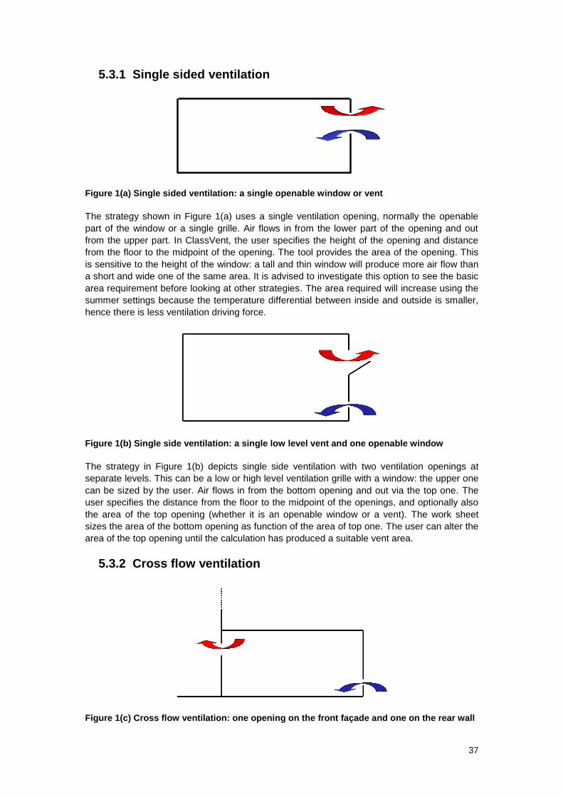
37
5.3.1 Single sided ventilation
Figure 1(a) Single sided ventilation: a single openable window or vent
The strategy shown in Figure 1(a) uses a single ventilation opening, normally the openable
part of the window or a single grille. Air flows in from the lower part of the opening and out
from the upper part. In ClassVent, the user specifies the height of the opening and distance
from the floor to the midpoint of the opening. The tool provides the area of the opening. This
is sensitive to the height of the window: a tall and thin window will produce more air flow than
a short and wide one of the same area. It is advised to investigate this option to see the basic
area requirement before looking at other strategies. The area required will increase using the
summer settings because the temperature differential between inside and outside is smaller,
hence there is less ventilation driving force.
Figure 1(b) Single side ventilation: a single low level vent and one openable window
The strategy in Figure 1(b) depicts single side ventilation with two ventilation openings at
separate levels. This can be a low or high level ventilation grille with a window: the upper one
can be sized by the user. Air flows in from the bottom opening and out via the top one. The
user specifies the distance from the floor to the midpoint of the openings, and optionally also
the area of the top opening (whether it is an openable window or a vent). The work sheet
sizes the area of the bottom opening as function of the area of top one. The user can alter the
area of the top opening until the calculation has produced a suitable vent area.
5.3.2 Cross flow ventilation
Figure 1(c) Cross flow ventilation: one opening on the front façade and one on the rear wall
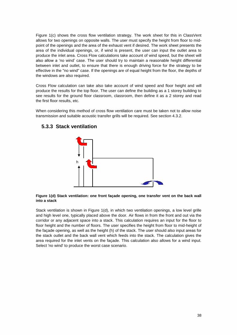
38
Figure 1(c) shows the cross flow ventilation strategy. The work sheet for this in ClassVent
allows for two openings on opposite walls. The user must specify the height from floor to mid-
point of the openings and the area of the exhaust vent if desired. The work sheet presents the
area of the individual openings, or, if wind is present, the user can input the outlet area to
produce the inlet area. Cross Flow calculations take account of wind speed, but the sheet will
also allow a ‘no wind’ case. The user should try to maintain a reasonable height differential
between inlet and outlet, to ensure that there is enough driving force for the strategy to be
effective in the "no wind" case. If the openings are of equal height from the floor, the depths of
the windows are also required.
Cross Flow calculation can take also take account of wind speed and floor height and will
produce the results for the top floor. The user can define the building as a 1 storey building to
see results for the ground floor classroom, classroom, then define it as a 2 storey and read
the first floor results, etc.
When considering this method of cross flow ventilation care must be taken not to allow noise
transmission and suitable acoustic transfer grills will be required. See section 4.3.2.
5.3.3 Stack ventilation
Figure 1(d) Stack ventilation: one front façade opening, one transfer vent on the back wall
into a stack
Stack ventilation is shown in Figure 1(d), in which two ventilation openings, a low level grille
and high level one, typically placed above the door. Air flows in from the front and out via the
corridor or any adjacent space into a stack. This calculation requires an input for the floor to
floor height and the number of floors. The user specifies the height from floor to mid-height of
the façade opening, as well as the height (h) of the stack. The user should also input areas for
the stack outlet and the back wall vent which feeds into the stack. The calculation gives the
area required for the inlet vents on the façade. This calculation also allows for a wind input.
Select 'no wind' to produce the worst case scenario.
h
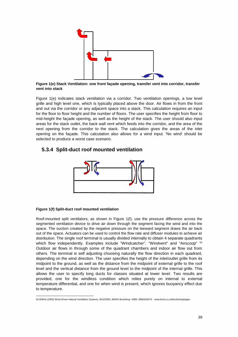
39
Figure 1(e) Stack Ventilation: one front façade opening, transfer vent into corridor, transfer
vent into stack
Figure 1(e) indicates stack ventilation via a corridor. Two ventilation openings, a low level
grille and high level one, which is typically placed above the door. Air flows in from the front
and out via the corridor or any adjacent space into a stack. This calculation requires an input
for the floor to floor height and the number of floors. The user specifies the height from floor to
mid-height the façade opening, as well as the height of the stack. The user should also input
areas for the stack outlet, the back wall vent which feeds into the corridor, and the area of the
next opening from the corridor to the stack. The calculation gives the areas of the inlet
opening on the façade. This calculation also allows for a wind input. 'No wind' should be
selected to produce a worst case scenario.
5.3.4 Split-duct roof mounted ventilation
Figure 1(f) Split-duct roof mounted ventilation
Roof-mounted split ventilators, as shown in Figure 1(f), use the pressure difference across the
segmented ventilation device to drive air down through the segment facing the wind and into the
space. The suction created by the negative pressure on the leeward segment draws the air back
out of the space. Actuators can be used to control the flow rate and diffuser modules to achieve air
distribution. The single roof terminal is usually divided internally to obtain 4 separate quadrants
which flow independently. Examples include "Windcatcher", "Windvent" and "Airscoop" 63
Outdoor air flows in through some of the quadrant chambers and indoor air flow out from
others. The terminal is self adjusting choosing naturally the flow direction in each quadrant,
depending on the wind direction. The user specifies the height of the inlet/outlet grille from its
midpoint to the ground, as well as the distance from the midpoint of external grille to the roof
level and the vertical distance from the ground level to the midpoint of the internal grille. This
allows the user to specify long ducts for classes situated at lower level. Two results are
provided, one for the windless condition which relies purely on internal to external
temperature differential, and one for when wind is present, which ignores buoyancy effect due
to temperature.
63 BSRIA (2005) Wind-Driven Natural Ventilation Systems, BG2/2005, BSRIA Bookshop: ISBN: 0860226476 - www.bsria.co.uk/bookshop/pages
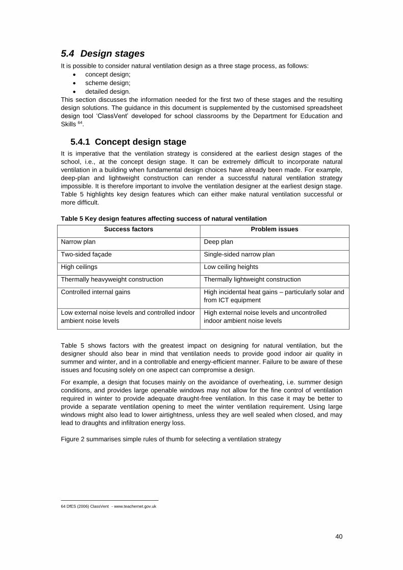
40
5.4 Design stages
It is possible to consider natural ventilation design as a three stage process, as follows:
concept design;
scheme design;
detailed design.
This section discusses the information needed for the first two of these stages and the resulting
design solutions. The guidance in this document is supplemented by the customised spreadsheet
design tool ‘ClassVent’ developed for school classrooms by the Department for Education and
Skills 64.
5.4.1 Concept design stage
It is imperative that the ventilation strategy is considered at the earliest design stages of the
school, i.e., at the concept design stage. It can be extremely difficult to incorporate natural
ventilation in a building when fundamental design choices have already been made. For example,
deep-plan and lightweight construction can render a successful natural ventilation strategy
impossible. It is therefore important to involve the ventilation designer at the earliest design stage.
Table 5 highlights key design features which can either make natural ventilation successful or
more difficult.
Table 5 Key design features affecting success of natural ventilation
Success factors Problem issues
Narrow plan Deep plan
Two-sided façade Single-sided narrow plan
High ceilings Low ceiling heights
Thermally heavyweight construction Thermally lightweight construction
Controlled internal gains High incidental heat gains – particularly solar and
from ICT equipment
Low external noise levels and controlled indoor
ambient noise levels
High external noise levels and uncontrolled
indoor ambient noise levels
Table 5 shows factors with the greatest impact on designing for natural ventilation, but the
designer should also bear in mind that ventilation needs to provide good indoor air quality in
summer and winter, and in a controllable and energy-efficient manner. Failure to be aware of these
issues and focusing solely on one aspect can compromise a design.
For example, a design that focuses mainly on the avoidance of overheating, i.e. summer design
conditions, and provides large openable windows may not allow for the fine control of ventilation
required in winter to provide adequate draught-free ventilation. In this case it may be better to
provide a separate ventilation opening to meet the winter ventilation requirement. Using large
windows might also lead to lower airtightness, unless they are well sealed when closed, and may
lead to draughts and infiltration energy loss.
Figure 2 summarises simple rules of thumb for selecting a ventilation strategy
64 DfES (2006) ClassVent - www.teachernet.gov.uk
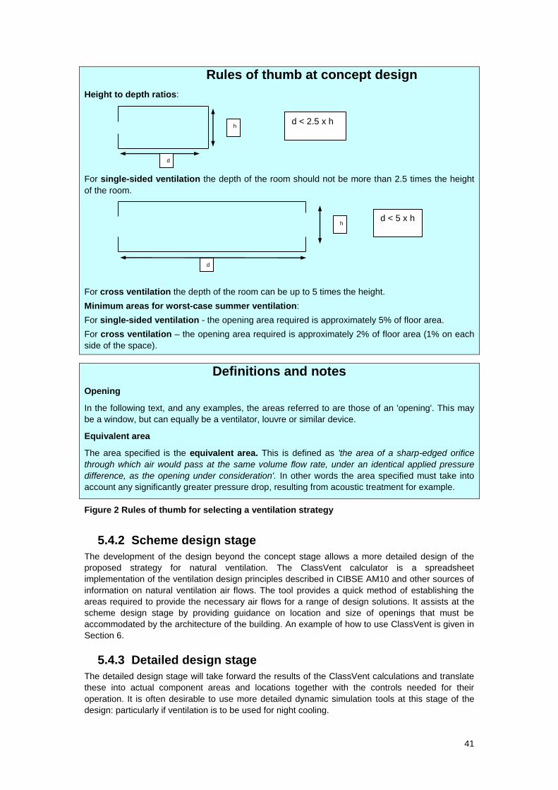
41
Rules of thumb at concept design
Height to depth ratios:
For single-sided ventilation the depth of the room should not be more than 2.5 times the height
of the room.
For cross ventilation the depth of the room can be up to 5 times the height.
Minimum areas for worst-case summer ventilation:
For single-sided ventilation - the opening area required is approximately 5% of floor area.
For cross ventilation – the opening area required is approximately 2% of floor area (1% on each
side of the space).
Figure 2 Rules of thumb for selecting a ventilation strategy
5.4.2 Scheme design stage
The development of the design beyond the concept stage allows a more detailed design of the
proposed strategy for natural ventilation. The ClassVent calculator is a spreadsheet
implementation of the ventilation design principles described in CIBSE AM10 and other sources of
information on natural ventilation air flows. The tool provides a quick method of establishing the
areas required to provide the necessary air flows for a range of design solutions. It assists at the
scheme design stage by providing guidance on location and size of openings that must be
accommodated by the architecture of the building. An example of how to use ClassVent is given in
Section 6.
5.4.3 Detailed design stage
The detailed design stage will take forward the results of the ClassVent calculations and translate
these into actual component areas and locations together with the controls needed for their
operation. It is often desirable to use more detailed dynamic simulation tools at this stage of the
design: particularly if ventilation is to be used for night cooling.
Definitions and notes
Opening
In the following text, and any examples, the areas referred to are those of an 'opening'. This may
be a window, but can equally be a ventilator, louvre or similar device.
Equivalent area
The area specified is the equivalent area. This is defined as 'the area of a sharp-edged orifice
through which air would pass at the same volume flow rate, under an identical applied pressure
difference, as the opening under consideration'. In other words the area specified must take into
account any significantly greater pressure drop, resulting from acoustic treatment for example.
h
d
h
d
d < 2.5 x h
d < 5 x h
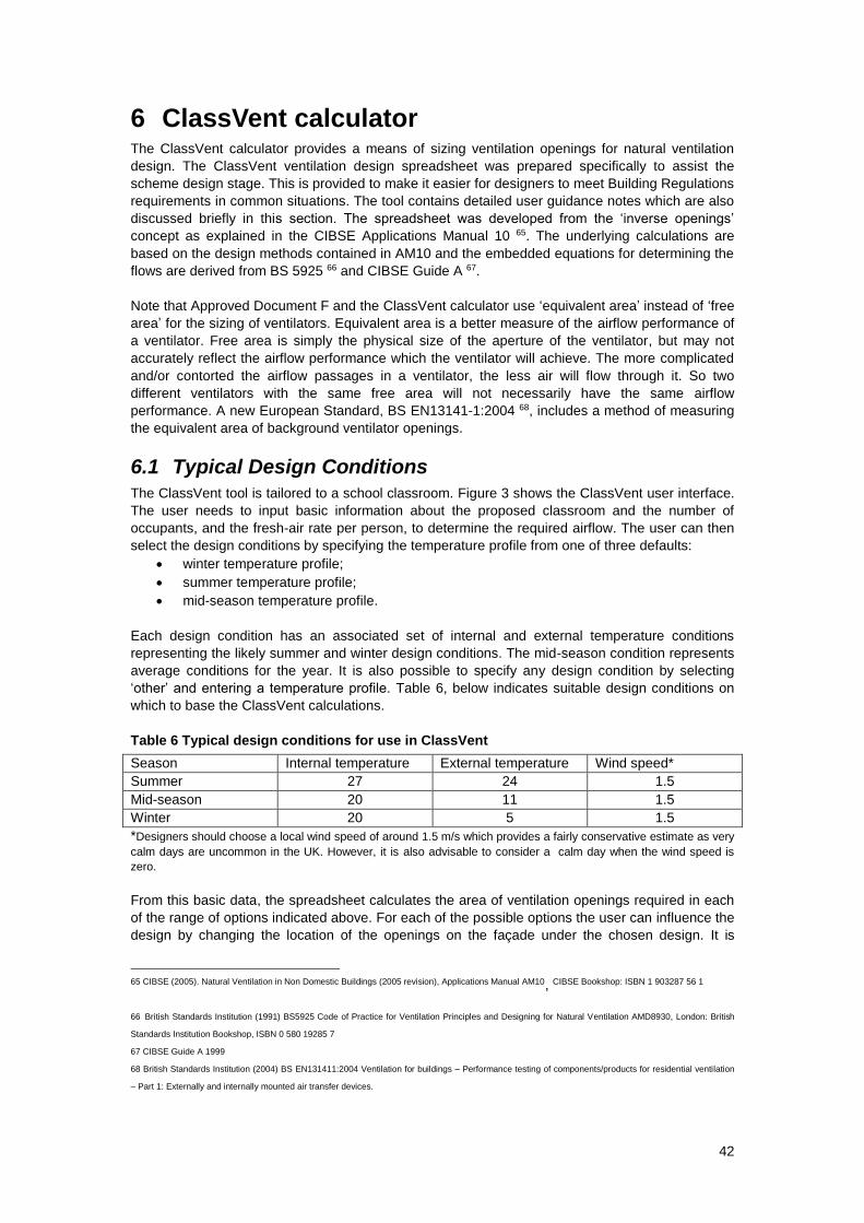
42
6 ClassVent calculator The ClassVent calculator provides a means of sizing ventilation openings for natural ventilation
design. The ClassVent ventilation design spreadsheet was prepared specifically to assist the
scheme design stage. This is provided to make it easier for designers to meet Building Regulations
requirements in common situations. The tool contains detailed user guidance notes which are also
discussed briefly in this section. The spreadsheet was developed from the ‘inverse openings’
concept as explained in the CIBSE Applications Manual 10 65. The underlying calculations are
based on the design methods contained in AM10 and the embedded equations for determining the
flows are derived from BS 5925 66 and CIBSE Guide A 67.
Note that Approved Document F and the ClassVent calculator use ‘equivalent area’ instead of ‘free
area’ for the sizing of ventilators. Equivalent area is a better measure of the airflow performance of
a ventilator. Free area is simply the physical size of the aperture of the ventilator, but may not
accurately reflect the airflow performance which the ventilator will achieve. The more complicated
and/or contorted the airflow passages in a ventilator, the less air will flow through it. So two
different ventilators with the same free area will not necessarily have the same airflow
performance. A new European Standard, BS EN13141-1:2004 68, includes a method of measuring
the equivalent area of background ventilator openings.
6.1 Typical Design Conditions
The ClassVent tool is tailored to a school classroom. Figure 3 shows the ClassVent user interface.
The user needs to input basic information about the proposed classroom and the number of
occupants, and the fresh-air rate per person, to determine the required airflow. The user can then
select the design conditions by specifying the temperature profile from one of three defaults:
winter temperature profile;
summer temperature profile;
mid-season temperature profile.
Each design condition has an associated set of internal and external temperature conditions
representing the likely summer and winter design conditions. The mid-season condition represents
average conditions for the year. It is also possible to specify any design condition by selecting
‘other’ and entering a temperature profile. Table 6, below indicates suitable design conditions on
which to base the ClassVent calculations.
Table 6 Typical design conditions for use in ClassVent
Season Internal temperature External temperature Wind speed*
Summer 27 24 1.5
Mid-season 20 11 1.5
Winter 20 5 1.5
*Designers should choose a local wind speed of around 1.5 m/s which provides a fairly conservative estimate as very
calm days are uncommon in the UK. However, it is also advisable to consider a calm day when the wind speed is
zero.
From this basic data, the spreadsheet calculates the area of ventilation openings required in each
of the range of options indicated above. For each of the possible options the user can influence the
design by changing the location of the openings on the façade under the chosen design. It is
65 CIBSE (2005). Natural Ventilation in Non Domestic Buildings (2005 revision), Applications Manual AM10, CIBSE Bookshop: ISBN 1 903287 56 1
66 British Standards Institution (1991) BS5925 Code of Practice for Ventilation Principles and Designing for Natural Ventilation AMD8930, London: British
Standards Institution Bookshop, ISBN 0 580 19285 7
67 CIBSE Guide A 1999
68 British Standards Institution (2004) BS EN131411:2004 Ventilation for buildings – Performance testing of components/products for residential ventilation
– Part 1: Externally and internally mounted air transfer devices.
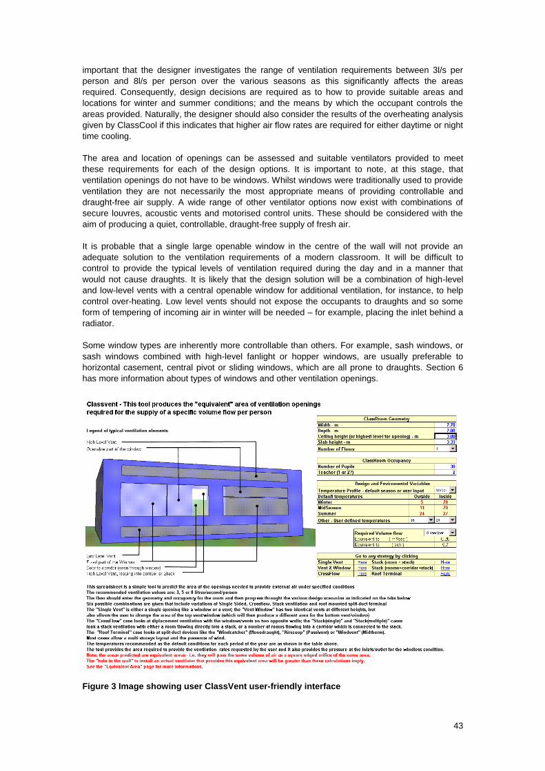
43
important that the designer investigates the range of ventilation requirements between 3l/s per
person and 8l/s per person over the various seasons as this significantly affects the areas
required. Consequently, design decisions are required as to how to provide suitable areas and
locations for winter and summer conditions; and the means by which the occupant controls the
areas provided. Naturally, the designer should also consider the results of the overheating analysis
given by ClassCool if this indicates that higher air flow rates are required for either daytime or night
time cooling.
The area and location of openings can be assessed and suitable ventilators provided to meet
these requirements for each of the design options. It is important to note, at this stage, that
ventilation openings do not have to be windows. Whilst windows were traditionally used to provide
ventilation they are not necessarily the most appropriate means of providing controllable and
draught-free air supply. A wide range of other ventilator options now exist with combinations of
secure louvres, acoustic vents and motorised control units. These should be considered with the
aim of producing a quiet, controllable, draught-free supply of fresh air.
It is probable that a single large openable window in the centre of the wall will not provide an
adequate solution to the ventilation requirements of a modern classroom. It will be difficult to
control to provide the typical levels of ventilation required during the day and in a manner that
would not cause draughts. It is likely that the design solution will be a combination of high-level
and low-level vents with a central openable window for additional ventilation, for instance, to help
control over-heating. Low level vents should not expose the occupants to draughts and so some
form of tempering of incoming air in winter will be needed – for example, placing the inlet behind a
radiator.
Some window types are inherently more controllable than others. For example, sash windows, or
sash windows combined with high-level fanlight or hopper windows, are usually preferable to
horizontal casement, central pivot or sliding windows, which are all prone to draughts. Section 6
has more information about types of windows and other ventilation openings.
Figure 3 Image showing user ClassVent user-friendly interface
44
7 Design Options
Once the ventilation strategy has been selected, and the size and location of the vents determined,
the type of vent opening and the means of control need to be chosen. This chapter gives some
guidance as to typical options that are available but others may be devised for specific
applications.
7.1 Vents
For natural ventilation systems vents typically fall into the following types; windows (including roof
lights), dampers, louvres, roof ventilators and trickle ventilators. All types of vent openings should
be assessed against the criteria outlined below:
Ventilation capacity will the device provide the required
airflow, given the pressure difference
available?
This will depend on the way the
vent opens and also for windows
on the enclosing head, sill and
jamb.
Controllability is the opening easily controlled by the
occupant?
This is desirable, and window
stays should be robust and
adjustable
Security is it secure for normal daytime use and
night cooling, if required?
The risk of security problems
from windows can be minimised
by restricting the length or throw
of stays or actuator arms.
Sealing will it be airtight when closed and is this
durable?
The life expectancy of seals
should be comparable to the life
of the window
Vent actuators can the actuators be combined with
automatic systems and are they quiet
in operation?
This should be considered with
care to maximise potential
performance.
Acoustic attenuation do the openings provide sufficient
sound insulation when in the open and
closed positions
7.1.1 Windows
Windows (together with doors and roof lights) have the advantage of being easily shut by the user
and are easy to seal effectively. It is also possible to control most window designs automatically
using actuators. Good window design is vital to ensure effective natural ventilation; different
window types have varying ventilation characteristics, acoustic properties and weather protection.
Their performance can be compromised by blinds, shutters or louvers used for solar control or
blackout purposes and this needs to be taken into account when selecting the window type. Some
of these features are described in Table 7.
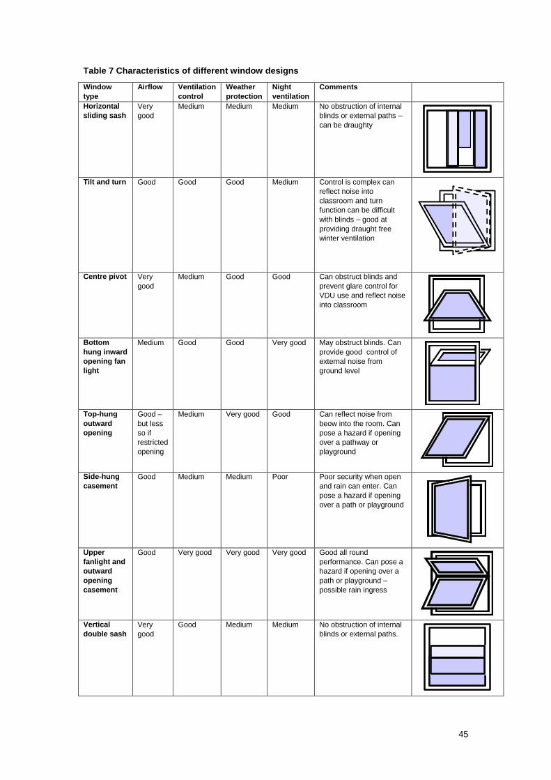
45
Table 7 Characteristics of different window designs
Window
type
Airflow Ventilation
control
Weather
protection
Night
ventilation
Comments
Horizontal
sliding sash
Very
good
Medium Medium Medium No obstruction of internal
blinds or external paths –
can be draughty
Tilt and turn Good Good Good Medium Control is complex can
reflect noise into
classroom and turn
function can be difficult
with blinds – good at
providing draught free
winter ventilation
Centre pivot Very
good
Medium Good Good Can obstruct blinds and
prevent glare control for
VDU use and reflect noise
into classroom
Bottom
hung inward
opening fan
light
Medium Good Good Very good May obstruct blinds. Can
provide good control of
external noise from
ground level
Top-hung
outward
opening
Good –
but less
so if
restricted
opening
Medium Very good Good Can reflect noise from
beow into the room. Can
pose a hazard if opening
over a pathway or
playground
Side-hung
casement
Good Medium Medium Poor Poor security when open
and rain can enter. Can
pose a hazard if opening
over a path or playground
Upper
fanlight and
outward
opening
casement
Good Very good Very good Very good Good all round
performance. Can pose a
hazard if opening over a
path or playground –
possible rain ingress
Vertical
double sash
Very
good
Good Medium Medium No obstruction of internal
blinds or external paths.
46
Horizontal pivot windows have a high ventilation capacity, and the geometry promotes good
distribution of supply air. Vertical pivot windows have similar characteristics to horizontal pivot
windows, but are vulnerable to driving rain. Interpane blinds may be needed as internal blinds are
impractical.
Vertical sliding sash windows are a good design solution for schools as they allow a choice
between high-level ventilation alone or in combination with low level for increased stack effect.
They do not intrude into the classroom and do not interfere with internal blinds. Sideways sliding
sashes have some of these attractions, but can lead to draughts at low level and usually lack fine
control of ventilation for occupant comfort. Sash windows also lend themselves to use in acoustic
labyrinth windows where a wide gap between outer and inner windows provides an acoustically
lined passage for the air. (See Building Bulletin 93 page 30 69).
Top- and bottom-hung windows provide the same level of flexibility as vertical sash windows and
can be used with a wide range of actuators. Bottom-hung inward opening windows are useful for
night cooling. For schools, the most appropriate windows are probably top- and bottom-hung
windows situated at high level and vertical sliding sashes situated at view window height.
Acoustic ventilators are available to improve the acoustic performance of a window; these can be fitted over window, above a transom or over the top of the window. It may also be possible to achieve the same effect as trickle ventilators through good window design (for example selected windows constantly open at very small opening angle). When selecting a window design, it is important to consider security and health and safety risks.
Top-hung and centre or horizontal pivot windows can pose a hazard when at low level, as building
users can walk into them when they are open. However, a suitable barrier such a planted border
can prevent this.
It should be noted that window sills, reveals, internal and external blinds have a major impact on
the equivalent area which is finally achieved. Further guidance on calculating the equivalent area
can be found in BS 5925: 1991 Code of practice for ventilation principles and designing for natural
ventilation70. The comments in section 4.4 regarding fire safety should also be noted.
The performance of windows can also be compromised by the operation of windows in a way that
was not intended by the designer. This can be avoided through proper consideration of practical,
health and safety and control issues at the design stage.
7.1.2 Dampers
Dampers are commonly used effectively in mechanical systems. In natural ventilation systems,
however, they do not shut as tight as most windows and often have poor insulation standards
resulting in condensation.
In natural ventilation systems they are usually used for air inlets below a false floor and at main
exhaust points, such as roofs. Standard blade dampers and sealed blade dampers are probably
the most appropriate for use in natural ventilation systems.
7.1.3 Louvres
Louvres usually have glazed or aluminium blades. Fitting security bars inside louvres enhances
their potential for night cooling. Some glass louvres have good seals, but these should be carefully
69 Department for Education and Skills (date). Acoustic Design of Schools – a design guide, Building Bulletin 93.
London: The Stationery Office. ISBN 0 11 271105 7 - www.teachernet.gov.uk
70 British Standards Institution (1991) BS5925 Code of Practice for Ventilation Principles and Designing for Natural Ventilation AMD8930
London: British Standards Institution Bookshop, ISBN 0 580 19285 7
47
selected and checked for construction and performance. Acoustic louvres or conventional weather
louvres backed by sound attenuators can also be used. Centre-pivot louvres provide improved
airflow compared with single-flap systems. Small louvres with little projection into the space can
avoid the potential clash with internal blinds. Louvres are available that can be controlled
automatically and linked to a building-management system.
7.1.4 Roof ventilators
Roof-mounted wind and stack ventilators are also available; wind from any direction strikes louvres
on the ventilator and is channelled down into the occupied space. At the same time, warm air rises
and is exhausted from the building on the down-wind side of the ventilator. Roof ventilators may be
suitable where external noise and security issues preclude the use of openable windows, and
where air at high level is cleaner than that at ground level. They also provide good night-time
cooling.
Roof-mounted terminals have a number of advantages over other methods of providing fresh air in
schools, and their use is now becoming common. Experience suggests that they offer a
combination of good ventilation and acoustic separation from external noise. They are generally
adopted for single-storey applications, but two-storey schools have used them successfully.
Some research suggests that these devices may not be effective on still days 71 and therefore they
are usually used in conjunction with other vents such as:
openable windows;
ducted air supply bringing fresh air in at ground level in schools with more than one
storey;
dampers to control the fresh air supply in response to internal and external conditions;
fan-assisted extract to provide additional air movement when the internal temperature is
high.
The detailed specification is best left to the manufacturers with performance curves for all of their
products.
7.1.5 Background trickle vents
Trickle vents can be integral to the window frame, part of the glazed unit or independent of the
window. However, they will not provide the minimum fresh-air rate required during occupancy
typical in classrooms, but can provide a very limited supply of fresh air out-of-hours.
Studies into the effectiveness of trickle vents in classrooms suggest that, in certain conditions, they
do not perform well. In ‘mid-year’ conditions, a single-sided ventilation strategy, with four trickle
vents each with free area of 4000 mm2 i.e. 16,000 mm2 of free area provided by inlets and outlets
of 8,000 mm2 vertically separated by 2 m, will only provide about one twentieth of the air required
and will definitely not provide adequate ventilation to ensure satisfactory indoor air quality for the
occupants. Trickle vents have a limited role in the provision of ventilation in schools.
Trickle-type ventilators are available which are wind limited and ‘throttle down’ according to
pressure difference across the ventilator, to reduce draught risks during windy weather. This is a
desirable feature, but they should be fitted with a manual control, so that they can be adjusted to
provide a lower ventilation rate in less airtight buildings.
71 See, for example, Gage S. A., Graham, J. M. R. “Static split duct roof ventilators”, Building Research & Information, Vol 28, No. 4, July 2000, pp 234-244
Kirk S., Kolokotroni M., (2004) “Windcatchers in Modern UK Buildings: Experimental Study”, International Journal of Ventilation, Vol 3, Issue 1, June 2004,
pp 67-78
48
7.1.6 Other openings and approaches
It is common to use combinations of opening types in an overall design. For example, motorised
dampers or louvres might supply fresh air to an under-floor plenum and air might be exhausted
from high-level windows. Combinations of window types in one unit might also be useful; for
example, a hopper (the top panes are pivoted horizontally to open inwards) over a centre pivot
window allows night ventilation and air to occupants deep in the room, whilst the centre pivot
allows high-summer ventilation rates.
7.2 Control of ventilation
7.2.1 Introduction
It is important that ventilation is controllable to maintain reasonable indoor air quality, and to avoid
draughts and waste of energy. Schools have traditionally been provided with local manual control
by the occupants, and this is recognised as being favoured by most building occupants – provided
it is readily controlled and does not compromise thermal comfort. However, one disadvantage of
user-controlled windows appears to be that teachers are reluctant to open them because of
possible noise, heat loss and security risks.
7.2.2 Occupant control
Occupants need to be able to control the ventilation system, regardless of the system used. For
example, activities in the classroom or unplanned spillages of odorous materials may require swift
and copious purge ventilation. This aspect of ventilation will be closely linked to the ventilator
provided or the window selection. Some ventilators incorporate a simple flap that allows users to
shut or open the ventilation provided, depending on internal and external conditions.
To ensure that controls are within reasonable reach of occupants it is recommended that they are
located in accordance with the guidance for Requirement N3 Safe opening and closing of windows
etc. Paragraph 3.2 of Approved Document N 72 (1998 edition):
Where controls can be reached without leaning over an obstruction they should not be
more than 1.9 m above the floor or other permanent stable surface provided to give
access. Small recesses, such as window reveals, should be ignored.
Where there is an obstruction the control should be lower, e.g. not more than 1.7 m where
there is a 600 mm deep obstruction (including any recess) not more than 900 mm high.
Where controls cannot be positioned within safe reach from a permanent stable surface, a
safe means of remote operation, such as a manual or electrical system, should be
provided.
Simple and intuitive controls may therefore provide the most reliable and robust solution. The use
of pull cords, operating rods, or similar devices may help to achieve this. These controls can either
be manual (i.e. operated by the occupant) or automatic.
It would be beneficial to provide the occupants with some visual display of the conditions in the
room. For example, this may be a display of the CO2 level either directly or by means of a ‘traffic
light’ system by which the occupants could judge the need for increased ventilation.
72 ODPM Building Regulations (2000): Approved Documents N, Glazing – safety in relation to impact, opening and cleaning, 1998 Edition, amended 2000,
London: The Stationery Office.

49
7.2.3 Automatic control
In today’s increasingly sophisticated school designs it is reasonable to consider the use of an
automatic natural ventilation system together with CO2 sensing. Given the inherent benefits of
natural ventilation, and that when well designed and properly controlled, its performance can
approach the equivalent consistency of indoor air quality as a mechanical system, it is important
that the designer fully explores its potential. The adoption of the performance standard approach to
ventilation as described in Section 1 lends itself to the use of an automatic control system using
CO2 sensing, and possibly temperature control to provide night-cooling control, and to limit
excessive heat loss in winter.
The use of sophisticated building management systems (BMS) is becoming widespread as the
technology becomes less costly. Using a BMS, together with sensors, such as local passive infra-
red detectors or CO2 concentration sensors located within the building, can maintain precise
control over the ventilation of the school. The control can also be linked to external weather
stations to modify the openings, depending on outside weather conditions.
This approach has been used in schools in England and Wales (and in Europe), and provides
good indoor air quality with minimum excess ventilation. It also ensures that compliance with the
performance standard is being achieved, as the BMS can record CO2 levels throughout the day.
7.2.4 Actuators
Actuators provide an automatic means of controlling vent openings. It is best, as a general rule, to
have one actuator per ventilator. The type of actuator suitable depends on a number of factors,
such as the location of the vent and manner of opening; the weight and size of vent; the travel and
free area to be achieved; available space and smoke ventilation. The types of actuators commonly
used for natural ventilation are:
linear push-pull piston actuators;
projecting chain drive push-pull actuators;
rack and pinion actuators;
linear sleeved cable or rod actuators: often visually intrusive and cumbersome, these are
used in some Victorian schools.
It is important that any window and ventilator operating mechanisms are virtually silent. They
should act as infrequently as possible, as even if they are of low noise, their intermittent operation
can cause serious disturbance to class activities if they are audible. Silence is achieved by
incrementally modulated actuators rather than fully open fully closed modulation. It is best if these
can be over-ridden by the teacher to provide purge ventilation when required.
7.3 Example of design study
The following example demonstrates the use of ClassVent to calculate the ventilation areas
required to provide a given ventilation rate. Note that the areas given are equivalent areas and the
physical dimensions of the actual vent or window will depend on its particular characteristics and
may need to be calculated separately to achieve this equivalent area. The example also indicates
how this affects the design option.
The following parameters are assumed for this example:
a standard classroom with a floor area of 54 m2 with 30 pupils and 2 adult occupants
the classroom meets the simple rule of thumb criterion (see section 5.4.1) for single-sided
ventilation
a ventilation rate of 8 l/s per person needs to be achieved for indoor air quality - note that
a higher rate may be needed for controlling overheating (see Section 8)
the periods of interest are winter, mid-season and summer and in this case, the conditions
suggested in Table 8 have been chosen.
50
wind conditions of zero wind (calm) 1.5 and 3.0m/s local wind speed
Table 8 Assumed design conditions for example case study
Period External temperature oC
Internal temperature oC
Comment
Winter 5 20 Lower than average day-time external temperature
Mid-season 11 20 Typical mid-season external temperature
Summer 24 27 High external and internal temperatures to give worst
case conditions.
7.3.1 Steady state calculation of area requirements using
ClassVent
Entering the basic input data into the ClassVent calculator allows assessment of the area
requirements for various design strategies. The results for six design strategies are shown in
Table 9 below. Note that the results are based on zero wind speed.
Table 9 ClassVent case study results for six design strategies at zero wind speed
Design condition Winter Mid season Summer
Design strategy Area 1
(m2)
Area 2
(m2)
Area 1
(m2)
Area 2
(m2)
Area 1
(m2)
Area 2
(m2)
Single sided - single opening
at 1.85m height
1.3 1.7 3.0
Single sided - equal area low
and high level openings
separation of 0.6 m
0.8 0.8 1.0 1.0 1.7 1.7
Cross flow - equal area
openings same height of 1m -
no wind
0.9 0.9 1.1 1.1 2.0 2.0
Cross flow - equal area
openings 1m height
separation - no wind
0.6 0.6 0.8 0.8 1.3 1.3
Opening with stack* 0.2 n/a 0.3 n/a 0.6 n/a
Roof terminal at 4m height –
inlet area on windward face
.3 .3 .6
- cross-sectional area of
complete duct
1 1.3 2.3
*Note: stack height 5m, stack opening 1 m2
Table 9 shows that the areas required to provide adequate ventilation for indoor air quality under
these temperature conditions, in the absence of the wind effect, varies from 0.2 m2 to more than
3 m2 depending on the strategy and design conditions. This indicates the need to carefully
investigate the various design options at the earliest stages of design – to ensure that the façade
can accommodate the areas required.
For any given strategy, the area requirement changes by a factor of two between the summer and
winter conditions; this necessitates provision of good control of installed vents, as they must be
capable of changing their areas over this range to give good control of the ventilation rate.
From the results of this preliminary set of calculations with ClassVent the most attractive option
without the use of a stack is the provision of openable areas on opposite sides of the classroom
with some vertical separation. This design solution is typical of a clerestory design commonly used
in schools and can be a highly effective strategy providing a combination of stack effect and wind
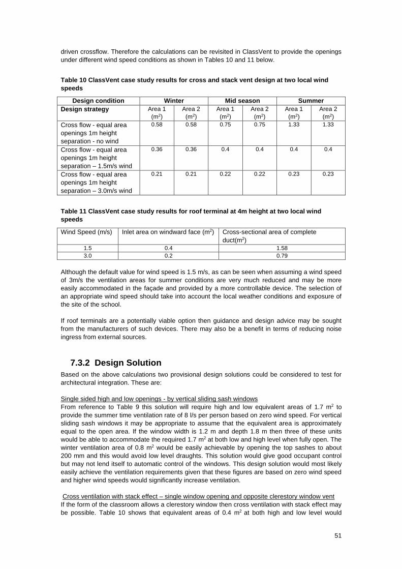
51
driven crossflow. Therefore the calculations can be revisited in ClassVent to provide the openings
under different wind speed conditions as shown in Tables 10 and 11 below.
Table 10 ClassVent case study results for cross and stack vent design at two local wind
speeds
Design condition Winter Mid season Summer
Design strategy Area 1
(m2)
Area 2
(m2)
Area 1
(m2)
Area 2
(m2)
Area 1
(m2)
Area 2
(m2)
Cross flow - equal area
openings 1m height
separation - no wind
0.58 0.58 0.75 0.75 1.33 1.33
Cross flow - equal area
openings 1m height
separation – 1.5m/s wind
0.36 0.36 0.4 0.4 0.4 0.4
Cross flow - equal area
openings 1m height
separation – 3.0m/s wind
0.21 0.21 0.22 0.22 0.23 0.23
Table 11 ClassVent case study results for roof terminal at 4m height at two local wind
speeds
Wind Speed (m/s) Inlet area on windward face (m2) Cross-sectional area of complete
duct(m2)
1.5 0.4 1.58
3.0 0.2 0.79
Although the default value for wind speed is 1.5 m/s, as can be seen when assuming a wind speed
of 3m/s the ventilation areas for summer conditions are very much reduced and may be more
easily accommodated in the façade and provided by a more controllable device. The selection of
an appropriate wind speed should take into account the local weather conditions and exposure of
the site of the school.
If roof terminals are a potentially viable option then guidance and design advice may be sought
from the manufacturers of such devices. There may also be a benefit in terms of reducing noise
ingress from external sources.
7.3.2 Design Solution
Based on the above calculations two provisional design solutions could be considered to test for
architectural integration. These are:
Single sided high and low openings - by vertical sliding sash windows
From reference to Table 9 this solution will require high and low equivalent areas of 1.7 m2 to
provide the summer time ventilation rate of 8 l/s per person based on zero wind speed. For vertical
sliding sash windows it may be appropriate to assume that the equivalent area is approximately
equal to the open area. If the window width is 1.2 m and depth 1.8 m then three of these units
would be able to accommodate the required 1.7 m2 at both low and high level when fully open. The
winter ventilation area of 0.8 m2 would be easily achievable by opening the top sashes to about
200 mm and this would avoid low level draughts. This solution would give good occupant control
but may not lend itself to automatic control of the windows. This design solution would most likely
easily achieve the ventilation requirements given that these figures are based on zero wind speed
and higher wind speeds would significantly increase ventilation.
Cross ventilation with stack effect – single window opening and opposite clerestory window vent
If the form of the classroom allows a clerestory window then cross ventilation with stack effect may
be possible. Table 10 shows that equivalent areas of 0.4 m2 at both high and low level would
52
provide the summertime ventilation at a wind speed of 1.5 m/s. To provide this equivalent area by
a casement window opened to 30 degrees would need a window area of approximately 0.7 m2
which could be provided by windows of very approximately 1.2 m by 0.6 m. These would need to
be provided both as clerestory windows and in the opposite façade.
This solution may not provide such good occupant control and draught free ventilation as the sash
windows but would lend itself more readily to automatic control and integration with a night cooling
strategy should this be required.
7.3.3 Summertime Overheating and ClassCool
These design solutions may be adequate to provide sufficient external air to maintain good indoor
air quality but it may not be sufficient to prevent overheating and thermal discomfort in summer.
Therefore, ClassCool (see section 8) should be used to check if the selected ventilation strategy
together with the other design features of the school is sufficient to control overheating. A degree
of iteration may be required before the final design strategy is selected.
53
8 Recommended Performance standard for the
control of summertime overheating
The DfES has produced the revised performance standard described below for compliance with
Part L2 of the building regulations for the avoidance of summertime overheating. This standard
supersedes previous standards as described in Building Bulletin 87.
8.1 Performance standard for the avoidance of overheating
Three parameters have been developed which indicate when overheating is likely to be
problematic. These standards apply outside the heating season and are for the occupied period of
09:00 to 15:30, Monday to Friday, from 1st May to 30th September.
the number of hours for which a threshold temperature is exceeded
the degree to which the internal temperature exceeds the external temperature
the maximum temperature experienced at any occupied time.
These performance parameters will ensure that the design of future schools is not dictated by a
single factor as previously but by a combination of factors that will allow a degree of flexibility in the
design of the school. They will also take account of the use of the school, for example in their
choice of term dates.
The performance standards for summertime overheating in compliance with Approved
document L2 for teaching and learning areas are:
a) There should be no more than 120 hours when the air temperature in the
classroom rises above 28°C
b) The average internal to external temperature difference should not exceed
5°C (i.e. the internal air temperature should be no more than 5°C above the
external air temperature on average)
c) The internal air temperature when the space is occupied should not exceed
32°C.
In order to show that the proposed school will not suffer overheating two of these three
criteria must be met.
To assist in determining possible overheating in classrooms as indicated by these performance
parameters, the ClassCool tool has been published by the DfES. ClassCool results are all
derived from annual simulations using the CIBSE London Test Reference Year. Currently air
temperature is used as this is the most appropriate from a historical perspective, and also ease of
measurement.
The ClassCool results are presented in terms of the above performance parameters and would
demonstrate compliance with the performance standards.
Note that other appropriate tools for predicting the required parameters can be used and if so
should use the geographically closest CIBSE Test Reference Year and be analysed according to
the guidance given in Section 8.4.2.
Note: the overheating criteria are for the thermal comfort of occupants and are not applicable for
equipment such as server rooms.
54
8.2 General guidance on avoiding overheating
Classrooms can be subject to substantial heat gains from electrical equipment, pupils and solar
gain. These internal gains, which provide useful heat in the heating season, can lead to
overheating in the summer and therefore should be reduced as much as possible by selection of
efficient appliances with low heat rejection. Energy labelling schemes for domestic equipment,
such as personal computers, cookers and other kitchen equipment, fridges, and washing
machines, indicate bands of energy efficiency. Selecting band A and B rated equipment will reduce
energy consumption. If less efficient equipment is used, then other elements of the building must
be improved to compensate for the increased equipment loads. In particular, summertime
overheating may result from excessive heat gains from inefficient equipment. Additional
information on the efficiencies of equipment can be found from the following websites:
www.ukepic.co.uk - UK Environmental Product Information Consortium
www.mtprog.co.uk - Market Transformation Programme
www.sedbuk.com - Boiler efficiency database
In some schools, electronic whiteboard projectors and overhead projectors are used for a large
part of the school. When in use, blinds are often drawn to improve the visibility of the screen and
this increases the heat load from the electric lights.
In addition to ensuring that all internal gains are reduced to a minimum, it is necessary to control
solar gains. For those sensitive areas that cannot be oriented to the north, some form of solar
shading may be required - either using special glass or blinds, or a combination of the two.
The first means of removing the unwanted heat is by natural ventilation. The ventilation rate for
cooling in summer is significantly more than the design capability supply rate (Section 1.4.2) that is
required for the hygiene of the occupants. Therefore, particular consideration should be given to
the design of the building, so that natural ventilation can achieve these supply rates.
Ideally, deep-plan spaces should be avoided and classrooms should have the provision for cross-
ventilation. As the worst situation is likely to be at times of high solar radiation, it may be possible
for the ventilation to be driven by a solar induced stack effect - solar chimneys are one way to
utilise this effect. This will encourage ventilation on days with little or no wind. It may be useful to
supplement the natural ventilation with fan assistance in a hybrid system for those times when the
design requirements (either for fresh air for IAQ or reduction of internal temperatures) are not
being met.
An undesirable rise in temperature during warm weather can be caused by uncontrolled incidental
and solar heat gains, or by high densities of occupation, e.g., in lecture rooms. In these
circumstances, sufficient natural ventilation is particularly important. Mechanical ventilation may be
necessary in some instances to help to control air temperature and sometimes cooling may be
required.
Reflective, white or very light roof surfaces reduce the solar heat gain through roofs as well as
reducing the thermal stress in weatherproof coverings, but will tend to become less effective
without adequate maintenance. Insulation in the roof and walls also helps to reduce this solar gain,
but will also reduce the ability of excess heat to escape from the space. Increased thermal mass in
the conditioned space controls the degree of temperature swing.
Excessive solar heat gain through windows can be minimised by appropriate orientation and by
the use of brise-soleil structural shading, louvres, blinds and curtains. Shading the glass from the
outside is the most effective method of control. However, this calls for careful design of sun
shading devices to avoid impairing the daylighting and ventilation of a classroom.
Incidental heat gains (e.g., solar, teaching equipment and light fittings) will contribute heat to the
space. Allowing for these and designing suitably responsive controls and heating systems will help
to reduce fuel consumption. With the increasing use of Information Communication Technology
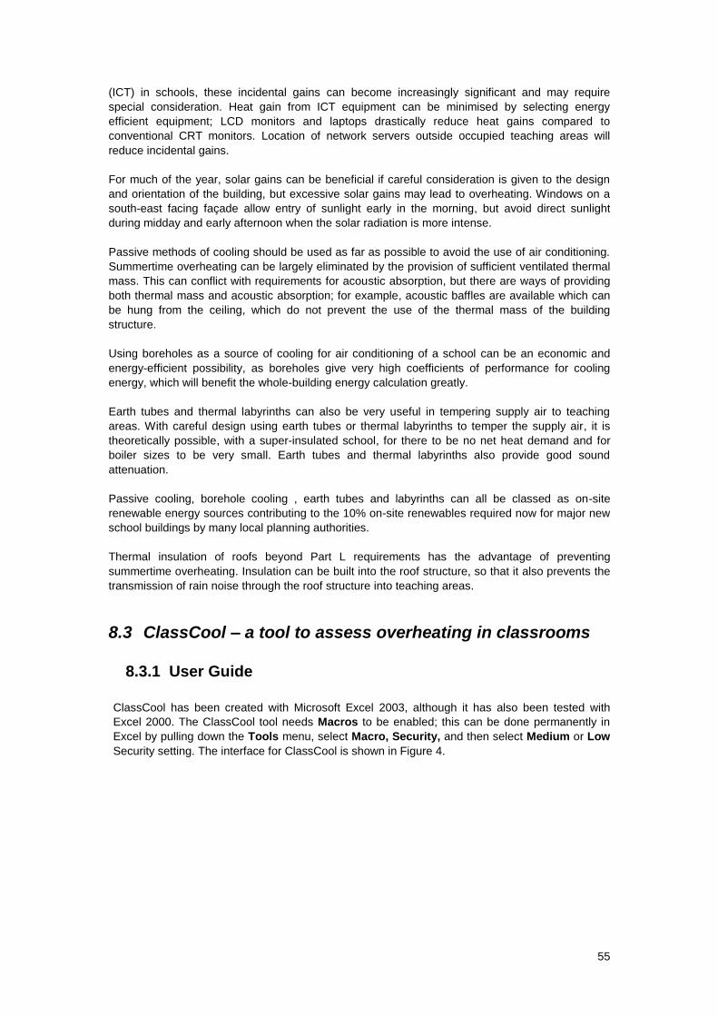
55
(ICT) in schools, these incidental gains can become increasingly significant and may require
special consideration. Heat gain from ICT equipment can be minimised by selecting energy
efficient equipment; LCD monitors and laptops drastically reduce heat gains compared to
conventional CRT monitors. Location of network servers outside occupied teaching areas will
reduce incidental gains.
For much of the year, solar gains can be beneficial if careful consideration is given to the design
and orientation of the building, but excessive solar gains may lead to overheating. Windows on a
south-east facing façade allow entry of sunlight early in the morning, but avoid direct sunlight
during midday and early afternoon when the solar radiation is more intense.
Passive methods of cooling should be used as far as possible to avoid the use of air conditioning.
Summertime overheating can be largely eliminated by the provision of sufficient ventilated thermal
mass. This can conflict with requirements for acoustic absorption, but there are ways of providing
both thermal mass and acoustic absorption; for example, acoustic baffles are available which can
be hung from the ceiling, which do not prevent the use of the thermal mass of the building
structure.
Using boreholes as a source of cooling for air conditioning of a school can be an economic and
energy-efficient possibility, as boreholes give very high coefficients of performance for cooling
energy, which will benefit the whole-building energy calculation greatly.
Earth tubes and thermal labyrinths can also be very useful in tempering supply air to teaching
areas. With careful design using earth tubes or thermal labyrinths to temper the supply air, it is
theoretically possible, with a super-insulated school, for there to be no net heat demand and for
boiler sizes to be very small. Earth tubes and thermal labyrinths also provide good sound
attenuation.
Passive cooling, borehole cooling , earth tubes and labyrinths can all be classed as on-site
renewable energy sources contributing to the 10% on-site renewables required now for major new
school buildings by many local planning authorities.
Thermal insulation of roofs beyond Part L requirements has the advantage of preventing
summertime overheating. Insulation can be built into the roof structure, so that it also prevents the
transmission of rain noise through the roof structure into teaching areas.
8.3 ClassCool – a tool to assess overheating in classrooms
8.3.1 User Guide
ClassCool has been created with Microsoft Excel 2003, although it has also been tested with
Excel 2000. The ClassCool tool needs Macros to be enabled; this can be done permanently in
Excel by pulling down the Tools menu, select Macro, Security, and then select Medium or Low
Security setting. The interface for ClassCool is shown in Figure 4.
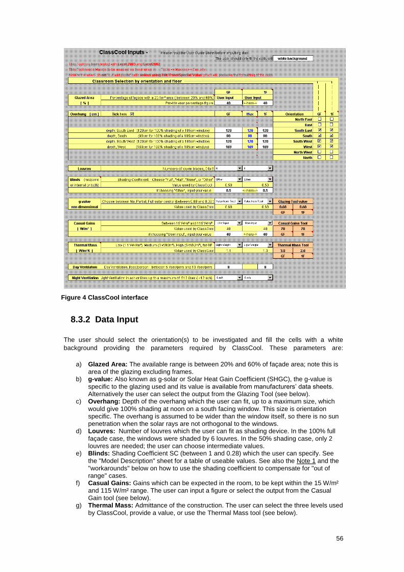
56
Figure 4 ClassCool interface
8.3.2 Data Input
The user should select the orientation(s) to be investigated and fill the cells with a white
background providing the parameters required by ClassCool. These parameters are:
a) Glazed Area: The available range is between 20% and 60% of façade area; note this is area of the glazing excluding frames.
b) g-value: Also known as g-solar or Solar Heat Gain Coefficient (SHGC), the g-value is specific to the glazing used and its value is available from manufacturers’ data sheets. Alternatively the user can select the output from the Glazing Tool (see below).
c) Overhang: Depth of the overhang which the user can fit, up to a maximum size, which would give 100% shading at noon on a south facing window. This size is orientation specific. The overhang is assumed to be wider than the window itself, so there is no sun penetration when the solar rays are not orthogonal to the windows.
d) Louvres: Number of louvres which the user can fit as shading device. In the 100% full façade case, the windows were shaded by 6 louvres. In the 50% shading case, only 2 louvres are needed; the user can choose intermediate values.
e) Blinds: Shading Coefficient SC (between 1 and 0.28) which the user can specify. See the "Model Description" sheet for a table of useable values. See also the Note 1 and the "workarounds" below on how to use the shading coefficient to compensate for "out of range" cases.
f) Casual Gains: Gains which can be expected in the room, to be kept within the 15 W/m² and 115 W/m² range. The user can input a figure or select the output from the Casual Gain tool (see below).
g) Thermal Mass: Admittance of the construction. The user can select the three levels used by ClassCool, provide a value, or use the Thermal Mass tool (see below).
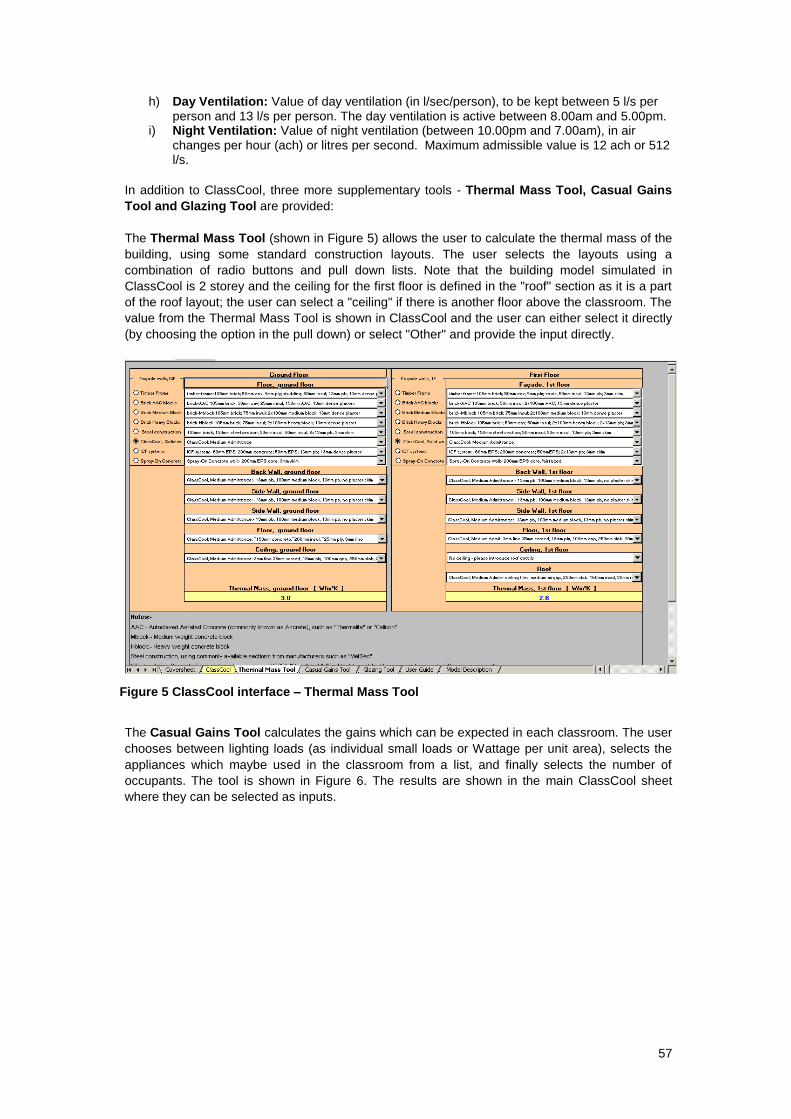
57
h) Day Ventilation: Value of day ventilation (in l/sec/person), to be kept between 5 l/s per person and 13 l/s per person. The day ventilation is active between 8.00am and 5.00pm.
i) Night Ventilation: Value of night ventilation (between 10.00pm and 7.00am), in air changes per hour (ach) or litres per second. Maximum admissible value is 12 ach or 512 l/s.
In addition to ClassCool, three more supplementary tools - Thermal Mass Tool, Casual Gains
Tool and Glazing Tool are provided:
The Thermal Mass Tool (shown in Figure 5) allows the user to calculate the thermal mass of the
building, using some standard construction layouts. The user selects the layouts using a
combination of radio buttons and pull down lists. Note that the building model simulated in
ClassCool is 2 storey and the ceiling for the first floor is defined in the "roof" section as it is a part
of the roof layout; the user can select a "ceiling" if there is another floor above the classroom. The
value from the Thermal Mass Tool is shown in ClassCool and the user can either select it directly
(by choosing the option in the pull down) or select "Other" and provide the input directly.
Figure 5 ClassCool interface – Thermal Mass Tool
The Casual Gains Tool calculates the gains which can be expected in each classroom. The user
chooses between lighting loads (as individual small loads or Wattage per unit area), selects the
appliances which maybe used in the classroom from a list, and finally selects the number of
occupants. The tool is shown in Figure 6. The results are shown in the main ClassCool sheet
where they can be selected as inputs.
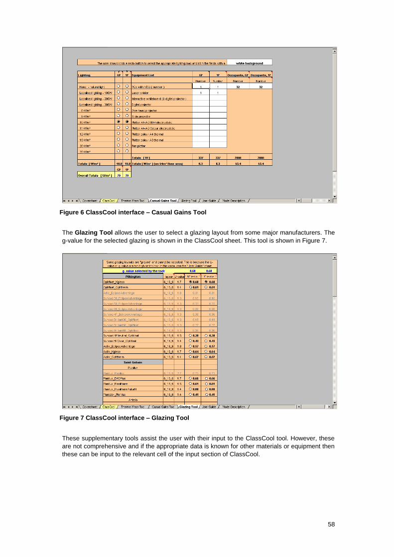
58
Figure 6 ClassCool interface – Casual Gains Tool
The Glazing Tool allows the user to select a glazing layout from some major manufacturers. The
g-value for the selected glazing is shown in the ClassCool sheet. This tool is shown in Figure 7.
Figure 7 ClassCool interface – Glazing Tool
These supplementary tools assist the user with their input to the ClassCool tool. However, these
are not comprehensive and if the appropriate data is known for other materials or equipment then
these can be input to the relevant cell of the input section of ClassCool.

59
8.4 Presentation of the Results
ClassCool provides three types of results, all derived from annual simulations using the CIBSE
London Test Reference Year, between Monday to Friday from 1st May to 30th September and
during occupied hours from 9.00am to 3.30pm. Currently air temperature is used as this is the
most appropriate from a historical perspective, and also ease of measurement.
a) ‘hours > 28°C’ [h]: A result above 120 h indicates serious overheating. This is the number of
occupied hours when the air temperature in the classroom rises above 28°C. This period include
approximately 6 weeks of ‘summer’, during which the class may in reality be unoccupied. This
period (24th July - 9th September) produces about a third of the overheating occurrences, hence
the recommendation not to exceed 120 h overheating, which is equivalent to the 80 h criterion
specified in the May 2003 edition of DfES Building Bulletin 87. This figure is rounded up to the
nearest multiple of 5 h.
b) ‘Avg Delta T’ [°C]: This is the average internal to external temperature difference during
occupied hours and a result above 5°C indicates serious overheating. The ClassCool predictions
of the temperature difference between indoor and outdoor are reasonably accurate. There is a
strong correlation between overheating occurrences and T, hence this is another marker for
overheating which can be used. Keeping T below 5°C should ensure that overheating is kept
within recommended guidelines.
c) ‘Max Tint’ [°C]: This is the maximum internal temperature during occupied hours and results
above 32°C indicate overheating. ClassCool is also reasonably accurate in predicting the
maximum temperature which could occur in the classroom. This is very useful as it defines the
quality of the overheating. Results above 35°C are not presented.
d) ‘Solar Gains’ (absolute [kWh] and relative to floor area [W/m²]): The solar gains can be used
to see the impact of the solar control strategies which can be adopted to control overheating. This
is not a criterion for compliance.
Notes:
1. The user should not confuse the Shading Coefficient (SC) for the blinds with the Shading Coefficient (SC) for the glazing; this is a property of the glazing layout and ‘somewhat superseded by the Solar Heat Gain Coefficient (SHGC) for most new applications’ (British Fenestration Rating Council - Window Energy Definitions).
2. The simulations were carried out using the CIBSE London Test Reference Year weather tape, which also specify the day of the week.
8.4.1 Using ClassCool
The user should input the required data and check that the classroom is not overheating,
interpreting the results as advised. If overheating
is occurring, the user may change some of the input parameters, for example:
a) reducing the amount of solar gains; this can be done in a variety of way, by:
i) reducing the size of the windows
ii) using some "solar control" glazing - i.e. modifying the g-value
iii) using some external shading devices such as overhangs or louvres
iv) using internal shading devices, such as midpane or internal blinds
b) changing the day ventilation levels, introducing a night ventilation strategy if not present
already or modifying its levels – this is an area of overlap with ClassVent and some iteration
between the two tools may be required to produce an acceptable design solution.
c) increasing the thermal mass of the building, which will cause room temperature changes
to occur more slowly
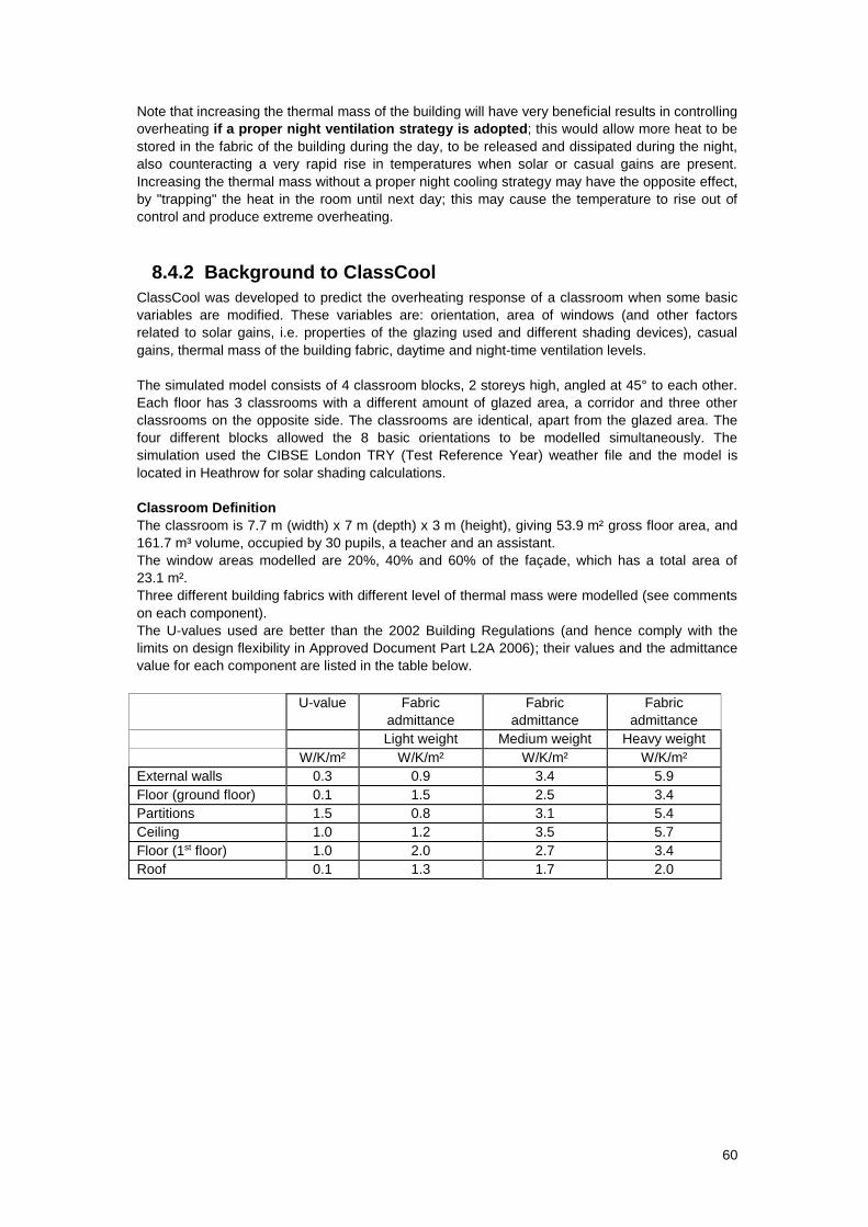
60
Note that increasing the thermal mass of the building will have very beneficial results in controlling
overheating if a proper night ventilation strategy is adopted; this would allow more heat to be
stored in the fabric of the building during the day, to be released and dissipated during the night,
also counteracting a very rapid rise in temperatures when solar or casual gains are present.
Increasing the thermal mass without a proper night cooling strategy may have the opposite effect,
by "trapping" the heat in the room until next day; this may cause the temperature to rise out of
control and produce extreme overheating.
8.4.2 Background to ClassCool
ClassCool was developed to predict the overheating response of a classroom when some basic
variables are modified. These variables are: orientation, area of windows (and other factors
related to solar gains, i.e. properties of the glazing used and different shading devices), casual
gains, thermal mass of the building fabric, daytime and night-time ventilation levels.
The simulated model consists of 4 classroom blocks, 2 storeys high, angled at 45° to each other.
Each floor has 3 classrooms with a different amount of glazed area, a corridor and three other
classrooms on the opposite side. The classrooms are identical, apart from the glazed area. The
four different blocks allowed the 8 basic orientations to be modelled simultaneously. The
simulation used the CIBSE London TRY (Test Reference Year) weather file and the model is
located in Heathrow for solar shading calculations.
Classroom Definition
The classroom is 7.7 m (width) x 7 m (depth) x 3 m (height), giving 53.9 m² gross floor area, and
161.7 m³ volume, occupied by 30 pupils, a teacher and an assistant.
The window areas modelled are 20%, 40% and 60% of the façade, which has a total area of
23.1 m².
Three different building fabrics with different level of thermal mass were modelled (see comments
on each component).
The U-values used are better than the 2002 Building Regulations (and hence comply with the
limits on design flexibility in Approved Document Part L2A 2006); their values and the admittance
value for each component are listed in the table below.
U-value Fabric
admittance
Fabric
admittance
Fabric
admittance
Light weight Medium weight Heavy weight
W/K/m² W/K/m² W/K/m² W/K/m²
External walls 0.3 0.9 3.4 5.9
Floor (ground floor) 0.1 1.5 2.5 3.4
Partitions 1.5 0.8 3.1 5.4
Ceiling 1.0 1.2 3.5 5.7
Floor (1st floor) 1.0 2.0 2.7 3.4
Roof 0.1 1.3 1.7 2.0
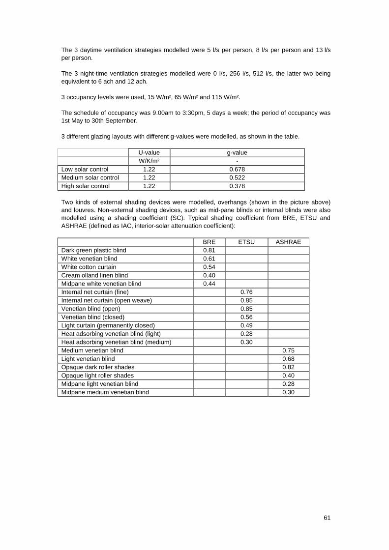
61
The 3 daytime ventilation strategies modelled were 5 l/s per person, 8 l/s per person and 13 l/s
per person.
The 3 night-time ventilation strategies modelled were 0 l/s, 256 l/s, 512 l/s, the latter two being
equivalent to 6 ach and 12 ach.
3 occupancy levels were used, 15 W/m², 65 W/m² and 115 W/m².
The schedule of occupancy was 9.00am to 3:30pm, 5 days a week; the period of occupancy was
1st May to 30th September.
3 different glazing layouts with different g-values were modelled, as shown in the table.
U-value g-value
W/K/m² -
Low solar control 1.22 0.678
Medium solar control 1.22 0.522
High solar control 1.22 0.378
Two kinds of external shading devices were modelled, overhangs (shown in the picture above)
and louvres. Non-external shading devices, such as mid-pane blinds or internal blinds were also
modelled using a shading coefficient (SC). Typical shading coefficient from BRE, ETSU and
ASHRAE (defined as IAC, interior-solar attenuation coefficient):
BRE ETSU ASHRAE
Dark green plastic blind 0.81
White venetian blind 0.61
White cotton curtain 0.54
Cream olland linen blind 0.40
Midpane white venetian blind 0.44
Internal net curtain (fine) 0.76
Internal net curtain (open weave) 0.85
Venetian blind (open) 0.85
Venetian blind (closed) 0.56
Light curtain (permanently closed) 0.49
Heat adsorbing venetian blind (light) 0.28
Heat adsorbing venetian blind (medium) 0.30
Medium venetian blind 0.75
Light venetian blind 0.68
Opaque dark roller shades 0.82
Opaque light roller shades 0.40
Midpane light venetian blind 0.28
Midpane medium venetian blind 0.30
