build your own quadrotor
DESCRIPTION
Build Your Own QuadrotorTRANSCRIPT
Open-Source
Projects on
Unmanned
Aerial Vehicles
•By Hyon Lim, Jaemann Park,Daewon Lee, and H.J. Kim
1070-9932/12/$31.00ª2012IEEE SEPTEMBER 2012 • IEEE ROBOTICS & AUTOMATION MAGAZINE • 33
Digital Object Identifier 10.1109/MRA.2012.2205629
Date of publication: 10 September 2012
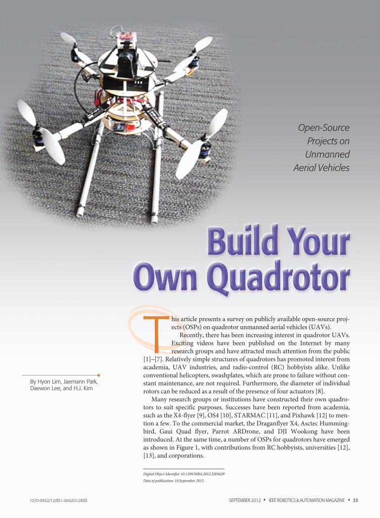
This article presents a survey on publicly available open-source proj-ects (OSPs) on quadrotor unmanned aerial vehicles (UAVs).
Recently, there has been increasing interest in quadrotor UAVs.Exciting videos have been published on the Internet by manyresearch groups and have attracted much attention from the public
[1]–[7]. Relatively simple structures of quadrotors has promoted interest fromacademia, UAV industries, and radio-control (RC) hobbyists alike. Unlikeconventional helicopters, swashplates, which are prone to failure without con-stant maintenance, are not required. Furthermore, the diameter of individualrotors can be reduced as a result of the presence of four actuators [8].
Many research groups or institutions have constructed their own quadro-tors to suit specific purposes. Successes have been reported from academia,such as the X4-flyer [9], OS4 [10], STARMAC [11], and Pixhawk [12] to men-tion a few. To the commercial market, the Draganflyer X4, Asctec Humming-bird, Gaui Quad flyer, Parrot ARDrone, and DJI Wookong have beenintroduced. At the same time, a number of OSPs for quadrotors have emergedas shown in Figure 1, with contributions from RC hobbyists, universities [12],[13], and corporations.
Quadrotor OSPs use community-hosting sites (e.g.,Google code and Github) to create code, blueprints, orschematics, which are freely available under open-sourcelicenses such as the general public license (GPL) [14].These tools help talented independent developers to join
OSPs freely from all over the world. This setting allowsvery fast development processes because new features canbe tested not only by the developer but also by otherpeople in the community. Feedback is given in real timefrom various conditions and configurations, which makeopen-source software more robust in a relatively shortperiod of time.
OSPs have been successful in many disciplines andremain competitive with commercial alternatives withLinux being the most famous operating system. In therobotics area, more than 2,000 projects have been estab-lished based on the robot operating system [15] with itswell-organized framework that encourages open-sourcedevelopment.
In the case of quadrotor OSPs, one of the main reasonsto use them is flexibility in both hardware and software,which makes modification easier to meet the specificrequirements of a user. In addition, OSPs allow researchersto replicate and extend the results of others and provide abaseline for comparison among various approaches.
In this article, we introduce eight quadrotor OSPs andcompare them in terms of hardware and software toprovide a compact overview for use in a variety of areas aswell as in academic research.
Open-Source Projects for Quadrotor UAVsIn this section, we introduce the quadrotor OSPs that arelisted in Table 1. These projects have been selected basedon the user volume, activity, and project maintenancestatus. All of these projects are still in development.Therefore, readers should note that the informationdescribed in this article is as of May 2012. We use the termOSP to refer to code, electronics, or auxiliary softwaresuch as the ground-control software (GCS), depending onthe context.
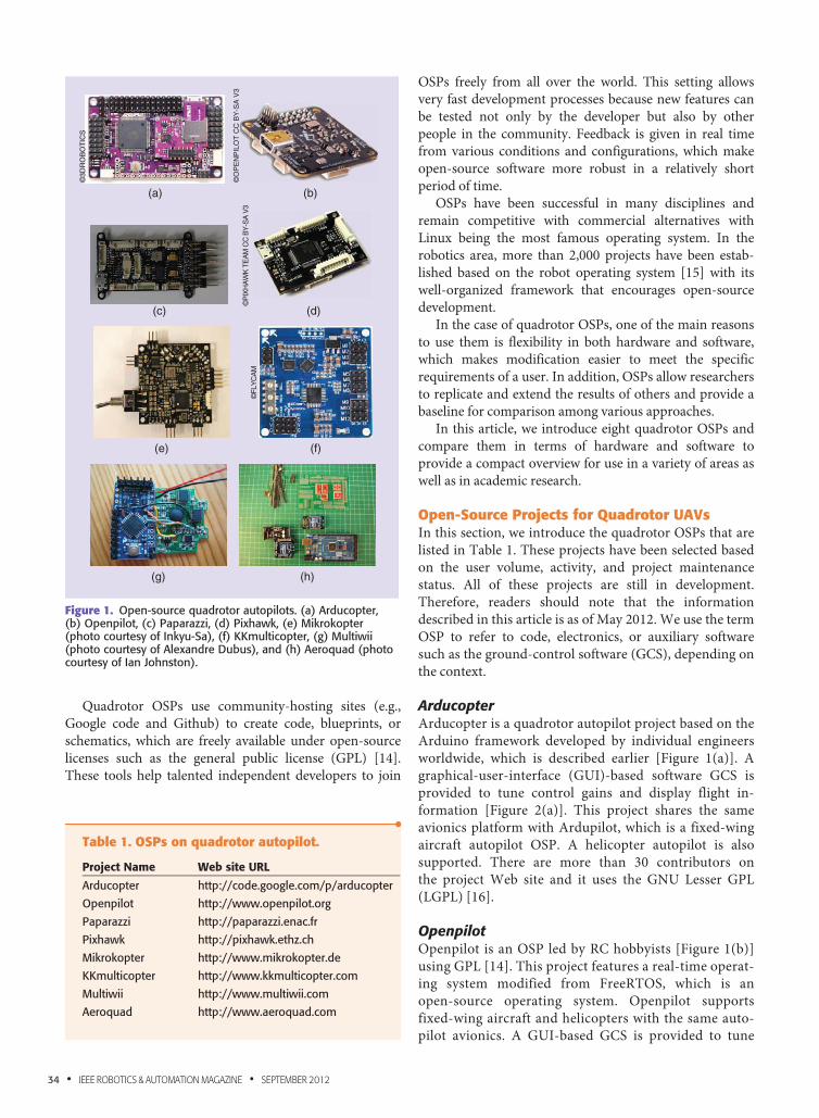
ArducopterArducopter is a quadrotor autopilot project based on theArduino framework developed by individual engineersworldwide, which is described earlier [Figure 1(a)]. Agraphical-user-interface (GUI)-based software GCS isprovided to tune control gains and display flight in-formation [Figure 2(a)]. This project shares the sameavionics platform with Ardupilot, which is a fixed-wingaircraft autopilot OSP. A helicopter autopilot is alsosupported. There are more than 30 contributors onthe project Web site and it uses the GNU Lesser GPL(LGPL) [16].
OpenpilotOpenpilot is an OSP led by RC hobbyists [Figure 1(b)]using GPL [14]. This project features a real-time operat-ing system modified from FreeRTOS, which is anopen-source operating system. Openpilot supportsfixed-wing aircraft and helicopters with the same auto-pilot avionics. A GUI-based GCS is provided to tune
(a) (b)
(c) (d)
(e) (f)
(h)(g)
©3D
RO
BO
TIC
S
©O
PE
NP
ILO
T C
C B
Y-S
A V
3©
PIX
HA
WK
TE
AM
CC
BY
-SA
V3
©FL
YC
AM
Figure 1. Open-source quadrotor autopilots. (a) Arducopter,(b) Openpilot, (c) Paparazzi, (d) Pixhawk, (e) Mikrokopter(photo courtesy of Inkyu-Sa), (f) KKmulticopter, (g) Multiwii(photo courtesy of Alexandre Dubus), and (h) Aeroquad (photocourtesy of Ian Johnston).
•Table 1. OSPs on quadrotor autopilot.
Project Name Web site URL
Arducopter http://code.google.com/p/arducopter
Openpilot http://www.openpilot.org
Paparazzi http://paparazzi.enac.fr
Pixhawk http://pixhawk.ethz.ch
Mikrokopter http://www.mikrokopter.de
KKmulticopter http://www.kkmulticopter.com
Multiwii http://www.multiwii.com
Aeroquad http://www.aeroquad.com
34 • IEEE ROBOTICS & AUTOMATION MAGAZINE • SEPTEMBER 2012
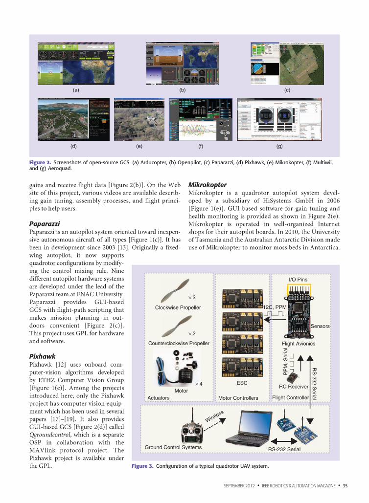
gains and receive flight data [Figure 2(b)]. On the Website of this project, various videos are available describ-ing gain tuning, assembly processes, and flight princi-ples to help users.
PaparazziPaparazzi is an autopilot system oriented toward inexpen-sive autonomous aircraft of all types [Figure 1(c)]. It hasbeen in development since 2003 [13]. Originally a fixed-wing autopilot, it now supportsquadrotor configurations by modify-ing the control mixing rule. Ninedifferent autopilot hardware systemsare developed under the lead of thePaparazzi team at ENAC University.Paparazzi provides GUI-basedGCS with flight-path scripting thatmakes mission planning in out-doors convenient [Figure 2(c)].This project uses GPL for hardwareand software.
PixhawkPixhawk [12] uses onboard com-puter-vision algorithms developedby ETHZ Computer Vision Group[Figure 1(e)]. Among the projectsintroduced here, only the Pixhawkproject has computer vision equip-ment which has been used in severalpapers [17]–[19]. It also providesGUI-based GCS [Figure 2(d)] calledQgroundcontrol, which is a separateOSP in collaboration with theMAVlink protocol project. ThePixhawk project is available underthe GPL.
MikrokopterMikrokopter is a quadrotor autopilot system devel-oped by a subsidiary of HiSystems GmbH in 2006[Figure 1(e)]. GUI-based software for gain tuning andhealth monitoring is provided as shown in Figure 2(e).Mikrokopter is operated in well-organized Internetshops for their autopilot boards. In 2010, the Universityof Tasmania and the Australian Antarctic Division madeuse of Mikrokopter to monitor moss beds in Antarctica.
(a) (b) (c)
(g)(f)(e)(d)
Figure 2. Screenshots of open-source GCS. (a) Arducopter, (b) Openpilot, (c) Paparazzi, (d) Pixhawk, (e) Mikrokopter, (f) Multiwii,and (g) Aeroquad.
Ground Control Systems
Actuators Motor ControllersMotor
Counterclockwise Propeller
Clockwise Propeller
× 4
× 2
× 2
ESC
RS-232 Serial
Flight Controller
RC Receiver
Flight Avionics
12C, PPM
I/O Pins
Sensors
RS
-232 Serial
PP
M, S
eria
l
Wireless
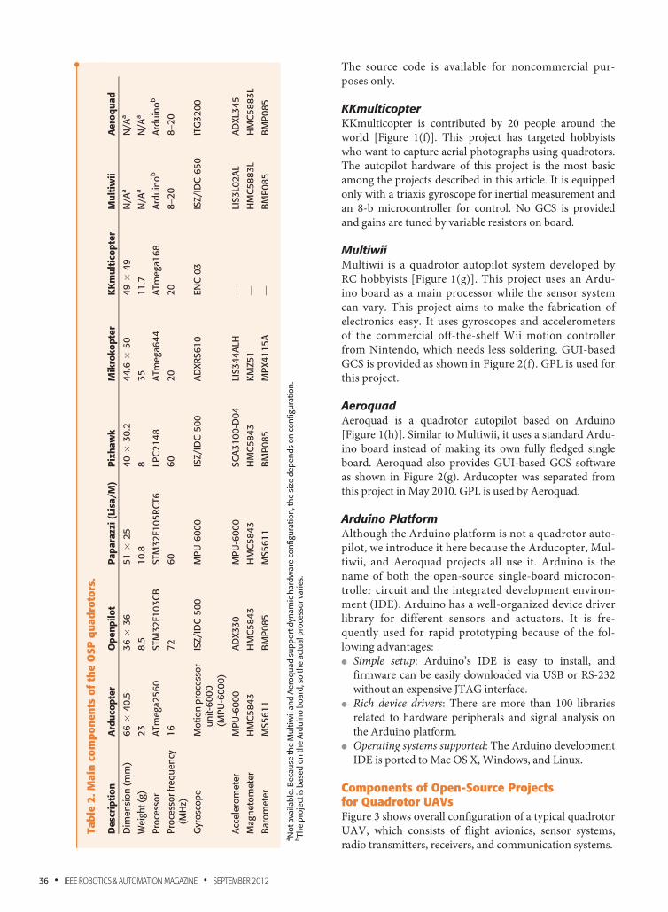
Figure 3. Configuration of a typical quadrotor UAV system.
SEPTEMBER 2012 • IEEE ROBOTICS & AUTOMATION MAGAZINE • 35
The source code is available for noncommercial pur-poses only.
KKmulticopterKKmulticopter is contributed by 20 people around theworld [Figure 1(f)]. This project has targeted hobbyistswho want to capture aerial photographs using quadrotors.The autopilot hardware of this project is the most basicamong the projects described in this article. It is equippedonly with a triaxis gyroscope for inertial measurement andan 8-b microcontroller for control. No GCS is providedand gains are tuned by variable resistors on board.
MultiwiiMultiwii is a quadrotor autopilot system developed byRC hobbyists [Figure 1(g)]. This project uses an Ardu-ino board as a main processor while the sensor systemcan vary. This project aims to make the fabrication ofelectronics easy. It uses gyroscopes and accelerometersof the commercial off-the-shelf Wii motion controllerfrom Nintendo, which needs less soldering. GUI-basedGCS is provided as shown in Figure 2(f). GPL is used forthis project.
AeroquadAeroquad is a quadrotor autopilot based on Arduino[Figure 1(h)]. Similar to Multiwii, it uses a standard Ardu-ino board instead of making its own fully fledged singleboard. Aeroquad also provides GUI-based GCS softwareas shown in Figure 2(g). Arducopter was separated fromthis project in May 2010. GPL is used by Aeroquad.
Arduino PlatformAlthough the Arduino platform is not a quadrotor auto-pilot, we introduce it here because the Arducopter, Mul-tiwii, and Aeroquad projects all use it. Arduino is thename of both the open-source single-board microcon-troller circuit and the integrated development environ-ment (IDE). Arduino has a well-organized device driverlibrary for different sensors and actuators. It is fre-quently used for rapid prototyping because of the fol-lowing advantages:l Simple setup: Arduino’s IDE is easy to install, and
firmware can be easily downloaded via USB or RS-232without an expensive JTAG interface.
l Rich device drivers: There are more than 100 librariesrelated to hardware peripherals and signal analysis onthe Arduino platform.
l Operating systems supported: The Arduino developmentIDE is ported to Mac OS X, Windows, and Linux.
Components of Open-Source Projectsfor Quadrotor UAVsFigure 3 shows overall configuration of a typical quadrotorUAV, which consists of flight avionics, sensor systems,radio transmitters, receivers, and communication systems.
•Ta
ble
2.M
ain
com
po
nen
tso
fth
eO
SP
qu
ad
roto
rs.
Desc
rip
tio
nA
rdu
cop
ter
Op
en
pilo
tP
ap
ara
zzi
(Lis
a/M
)P
ixh
aw
kM
ikro
ko
pte
rK
Km
ult
ico
pte
rM
ult
iwii
Aero
qu
ad
Dim
en
sio
n(m
m)
66
34
0.5
36
33
65
13
25
40
33
0.2
44
.63
50
49
34
9N
/Aa
N/A
a
Weig
ht(g
)2
38
.51
0.8
83
51
1.7
N/A
aN
/Aa
Pro
cess
or
ATm
ega2
56
0STM
32
F10
3C
BSTM
32
F10
5R
CT6
LPC
21
48
ATm
ega6
44
ATm
ega1
68
Ard
uin
ob
Ard
uin
ob
Pro
cess
orfr
eq
uen
cy(M
Hz)
16
72
60
60
20
20
8–2
08–2
0
Gyr
osc
op
eM
otio
np
roce
sso
ru
nit-6
00
0(M
PU
-60
00
)
ISZ/I
DC
-50
0M
PU
-60
00
ISZ/I
DC
-50
0A
DXR
S6
10
EN
C-0
3IS
Z/I
DC
-65
0IT
G3
20
0
Acc
ele
rom
ete
rM
PU
-60
00
AD
X3
30
MP
U-6
00
0SC
A3
10
0-D
04
LIS3
44
ALH
—LI
S3
L02
AL
AD
XL3
45
Magn
eto
mete
rH
MC
58
43
HM
C5
84
3H
MC
58
43
HM
C5
84
3K
MZ5
1—
HM
C5
88
3L
HM
C5
88
3L
Baro
mete
rM
S5
61
1B
MP
08
5M
S5
61
1B
MP
08
5M
PX4
11
5A
—B
MP
08
5B
MP
08
5
aN
otava
ilab
le.B
eca
use
the
Mu
ltiw
iian
dA
ero
qu
ad
sup
po
rtd
ynam
ich
ard
ware
con
figu
ratio
n,t
he
size
dep
en
ds
on
con
figu
ratio
n.
bTh
ep
roje
ctis
base
do
nth
eA
rdu
ino
bo
ard
,so
the
act
ualp
roce
sso
rva
ries.
36 • IEEE ROBOTICS & AUTOMATION MAGAZINE • SEPTEMBER 2012
Flight AvionicsFlight avionics for the various projects mentioned in thesection “Open-Source Projects for Quadrotor UAVs” areshown in Figure 1. Most of the introduced projects provideelectronic schematics for self-production. Typically, flightavionics consists of a processor, input/output (I/O) pins,and sensors. The I/O pins connect an off-the-shelf
electronic speed controller (ESC) and RC receiver to theflight controller. The sensor suite consists of a gyroscope,accelerometer, barometer, magnetometer, and global posi-tioning system (GPS).
Table 2 describes flight avionics composition. Mostflight avionics are full-fledged with six degrees of freedom(6DoF) inertial measurement unit (IMU), magnetometer,
•Table 3. Specifications of accelerometers.
Chip Name Outputs AxisSupply(V)
Power(mA)
MeasurementRange (g)
Bandwidth(kHz)
Nonlinearity(%) Dimension (mm)
ADXL330 Voltage Three axes 1.8–3.6 0.32 �3 1.6 (XY),0.55 (Z)
�0.3 4.0 3 4.0 3 1.45
SCA3100-D04 SPI Three axes 3.0–3.6 3 �2 2 �2 7.6 3 3.3 3 8.6
LIS344ALH Voltage Three axes 2.4–3.6 0.68 �6 1.8 �0.5 4.0 3 4.0 3 1.5
MPU-6000 I2C Three axes 2.375–3.46 0.5 �16 1 �0.5 4.0 3 4.0 3 0.9
LIS3L02AL Voltage Three axes 3.4–3.6 0.85 �2 1.5 �0.3 (XY),�0.5 (Z)
5.0 3 5.0 3 1.52
•Table 4. Specifications of gyroscopes.
Chip Name Outputs AxisSupply(V)
Power(mA)
Range(degree/s)
Response(Hz max.) Dimension (mm)
ENC-03 Voltage One axis 2.7–5.5 5 �300 50 15.5 3 8.0 3 4.3
IDG-500 Voltage Two axes (XY) 2.7–3.3 7 �500 140 4.5 3 5.0 3 1.2
ISG-500 Voltage One axis (Z) 2.7–3.3 4.5 �500 140 4.0 3 5.0 3 1.15
IDC-650 Voltage Two axes (XY) 2.7–3.3 7 �2,000 140 4.0 3 5.0 3 1.15
ISG-650 Voltage One axis (Z) 2.7–3.3 4.5 �2,000 140 4.0 3 5.0 3 1.15
ADXRS610 Voltage One axis 4.75–5.25 3.5 �300 2,500 7.0 3 7.0 3 3.0
MPU-6000 I2C Three axes 2.375–3.46 3.6 �2,000 256 5.0 3 5.0 3 1.52
•Table 5. Specifications of magnetometers.
Chip Name Outputs Axis Supply (V) Power (Ma) Range (G) Rate (Hz) Dimension (mm)
HMC5843 I2C Three axes 2.5–3.3 0.8 �4 116 4.0 3 4.0 3 1.3
HMC5883 I2C Three axes 1.6–3.3 0.64 �8 116 3.0 3 3.0 3 0.9
KMZ51 Voltage One axis 5.0–8.0 — �2.5 — 5.0 3 4.0 3 1.75
•Table 6. Specifications of barometers.
Chip Name Interface Supply VoltagePowerConsumption Range
Response Time(ms)
Dimension(mm)
MPX4115A Analog(voltage)
4.85–5.35 0.1 mA (max) 150–1150 hPa 1 11.38 3 10.54 3 12.7
BMP085 I2C 1.8–3.6 5 lA 300–1100 hPa 7.5 5.0 3 5.0 3 1.2
MS5611 I2C 1.8–3.6 0.9–12.5 lA 450–1100 mBar 0.5–8.22 3.0 3 5.0 3 1.7
SEPTEMBER 2012 • IEEE ROBOTICS & AUTOMATION MAGAZINE • 37
and barometer. However, KKmulticopter has only threegyroscopes, because it is devoted to manual flight. KKmul-ticopter implements a stability augmented system (SAS),which will be discussed in the section “Open-SourceProjects Internals.” Most flight controllers implement pro-portional-integral-derivative (PID) control for stabiliza-tion of the quadrotor, although the structure of the PIDcontrollers between the projects varies slightly. This willalso be discussed in detail in the section “Open-SourceProjects Internals.”
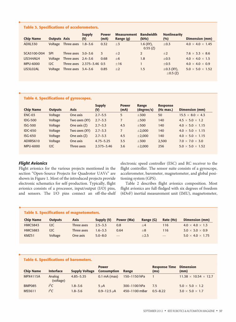
SensorsDetailed specification of the sensors used in the OSPsis given in Tables 3–6. For the accelerometer, five differ-ent chips are used in the OSPs, which are shown inTable 3. For the gyroscope, there are seven differentchips used as listed in Table 4. Magnetometers are usedto correct attitude information and estimate drift ofgyroscopes. There are three different magnetometersused in the OSPs as shown in Table 5. Three typesof barometers used to measure altitude are shownin Table 6.
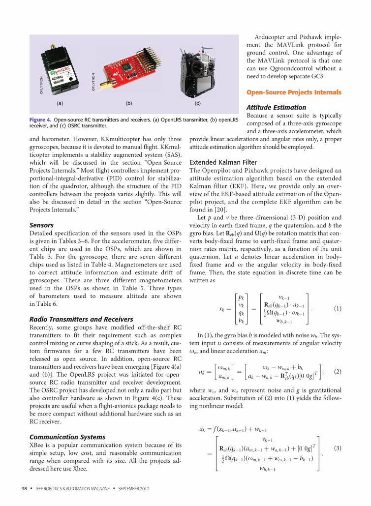
Radio Transmitters and ReceiversRecently, some groups have modified off-the-shelf RCtransmitters to fit their requirement such as complexcontrol mixing or curve shaping of a stick. As a result, cus-tom firmwares for a few RC transmitters have beenreleased as open source. In addition, open-source RCtransmitters and receivers have been emerging [Figure 4(a)and (b)]. The OpenLRS project was initiated for open-source RC radio transmitter and receiver development.The OSRC project has developed not only a radio part butalso controller hardware as shown in Figure 4(c). Theseprojects are useful when a flight-avionics package needs tobe more compact without additional hardware such as anRC receiver.
Communication SystemsXBee is a popular communication system because of itssimple setup, low cost, and reasonable communicationrange when compared with its size. All the projects ad-dressed here use Xbee.
Arducopter and Pixhawk imple-ment the MAVLink protocol forground control. One advantage ofthe MAVLink protocol is that onecan use Qgroundcontrol without aneed to develop separate GCS.
Open-Source Projects Internals
Attitude EstimationBecause a sensor suite is typicallycomposed of a three-axis gyroscopeand a three-axis accelerometer, which
provide linear accelerations and angular rates only, a properattitude estimation algorithm should be employed.
Extended Kalman FilterThe Openpilot and Pixhawk projects have designed anattitude estimation algorithm based on the extendedKalman filter (EKF). Here, we provide only an over-view of the EKF-based attitude estimation of the Open-pilot project, and the complete EKF algorithm can befound in [20].
Let p and v be three-dimensional (3-D) position andvelocity in earth-fixed frame, q the quaternion, and b thegyro bias. Let Reb(q) and X(q) be rotation matrix that con-verts body-fixed frame to earth-fixed frame and quater-nion rates matrix, respectively, as a function of the unitquaternion. Let a denotes linear acceleration in body-fixed frame and x the angular velocity in body-fixedframe. Then, the state equation in discrete time can bewritten as
xk ¼
pkvkqkbk
2664
3775 ¼
vk�1Reb(qk�1) � ak�112X(qk�1) � xk�1
wb, k�1
2664
3775: (1)
In (1), the gyro bias b is modeled with noise wb. The sys-tem input u consists of measurements of angular velocityxm and linear acceleration am:
uk ¼xm, k
am, k
� �¼ xk � wx, k þ bk
ak � wa, k � RTeb(qk)½0 0g�T
� �, (2)
where wx and wa represent noise and g is gravitationalacceleration. Substitution of (2) into (1) yields the follow-ing nonlinear model:
xk ¼ f (xk�1, uk�1)þ wk�1
¼
vk�1Reb(qk�1)(am, k�1 þ wa, k�1)þ ½0 0g�T12X(qk�1)(xm, k�1 þ wx, k�1 � bk�1)
wb, k�1
26664
37775,
(3)
(a) (b) (c)
©F
LYT
RO
N
©F
LYT
RO
N
Figure 4. Open-source RC transmitters and receivers. (a) OpenLRS transmitter, (b) openLRSreceiver, and (c) OSRC transmitter.
38 • IEEE ROBOTICS & AUTOMATION MAGAZINE • SEPTEMBER 2012
where wk ¼ ½wx, k,wa, k,wb, k�T is process noise. The non-linear measurement model is (we omit time index k fornotational simplicity)
zk ¼ h(xk)þ vk ¼
pvmb
hb
2664
3775 ¼
pv
RTeb(q)me
�Pz
2664
3775, (4)
where mb is the measurement of the magnetic field of theearthme in body frame, hb is the heightmeasured by the baro-metric sensor reading Pz , and vk is the measurement noise.
The states are estimated by the standard EKF algorithmand measurements from accelerometers, gyroscopes,magnetometers, GPS, and barometer are fused to estimatethe states.
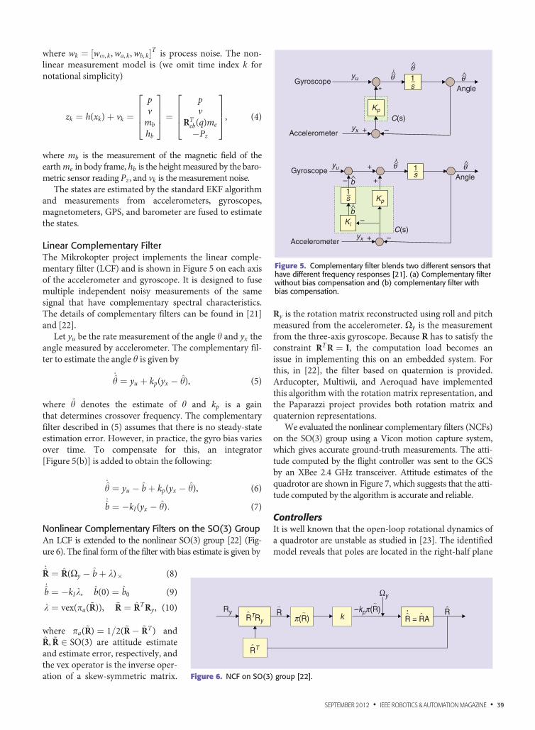
Linear Complementary FilterThe Mikrokopter project implements the linear comple-mentary filter (LCF) and is shown in Figure 5 on each axisof the accelerometer and gyroscope. It is designed to fusemultiple independent noisy measurements of the samesignal that have complementary spectral characteristics.The details of complementary filters can be found in [21]and [22].
Let yu be the rate measurement of the angle h and yx theangle measured by accelerometer. The complementary fil-ter to estimate the angle h is given by
_h ¼ yu þ kp(yx � h), (5)
where h denotes the estimate of h and kp is a gainthat determines crossover frequency. The complementaryfilter described in (5) assumes that there is no steady-stateestimation error. However, in practice, the gyro bias variesover time. To compensate for this, an integrator[Figure 5(b)] is added to obtain the following:
_h ¼ yu � bþ kp(yx � h), (6)
_b ¼ �kI(yx � h): (7)
Nonlinear Complementary Filters on the SO(3) GroupAn LCF is extended to the nonlinear SO(3) group [22] (Fig-ure 6). The final form of the filter with bias estimate is given by
_R ¼ R(Xy � bþ k)3 (8)
_b ¼ �kIk, b(0) ¼ b0 (9)
k ¼ vex(pa(~R)), ~R ¼ RTRy, (10)
where pa(~R) ¼ 1=2(~R� ~RT) andR, ~R 2 SO(3) are attitude estimateand estimate error, respectively, andthe vex operator is the inverse oper-ation of a skew-symmetric matrix.
Ry is the rotation matrix reconstructed using roll and pitchmeasured from the accelerometer. Xy is the measurementfrom the three-axis gyroscope. Because R has to satisfy theconstraint RTR ¼ I, the computation load becomes anissue in implementing this on an embedded system. Forthis, in [22], the filter based on quaternion is provided.Arducopter, Multiwii, and Aeroquad have implementedthis algorithm with the rotation matrix representation, andthe Paparazzi project provides both rotation matrix andquaternion representations.
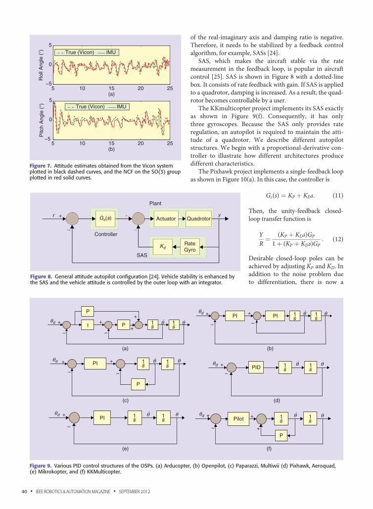
We evaluated the nonlinear complementary filters (NCFs)on the SO(3) group using a Vicon motion capture system,which gives accurate ground-truth measurements. The atti-tude computed by the flight controller was sent to the GCSby an XBee 2.4 GHz transceiver. Attitude estimates of thequadrotor are shown in Figure 7, which suggests that the atti-tude computed by the algorithm is accurate and reliable.
ControllersIt is well known that the open-loop rotational dynamics ofa quadrotor are unstable as studied in [23]. The identifiedmodel reveals that poles are located in the right-half plane
Ryk
Ωy
R = RAR
RT
^
^
^ ^^
RTRy–kpπ(R)
∼
π(R)∼R
∼
Figure 6. NCF on SO(3) group [22].
Accelerometer
Accelerometer
Gyroscope
Gyroscope– +
+
C(s)
C(s)
Kp
Kp
Ki
yu
yu
yx
yx
Angle
Angle
1s
1s
1s
+
+ –
–
–
θ∧
b∧
b∧
θ∧
θ∧
θ∧
θ∧
Figure 5. Complementary filter blends two different sensors thathave different frequency responses [21]. (a) Complementary filterwithout bias compensation and (b) complementary filter withbias compensation.
SEPTEMBER 2012 • IEEE ROBOTICS & AUTOMATION MAGAZINE • 39
of the real-imaginary axis and damping ratio is negative.Therefore, it needs to be stabilized by a feedback controlalgorithm, for example, SASs [24].
SAS, which makes the aircraft stable via the ratemeasurement in the feedback loop, is popular in aircraftcontrol [25]. SAS is shown in Figure 8 with a dotted-linebox. It consists of rate feedback with gain. If SAS is appliedto a quadrotor, damping is increased. As a result, the quad-rotor becomes controllable by a user.
The KKmulticopter project implements its SAS exactlyas shown in Figure 9(f). Consequently, it has onlythree gyroscopes. Because the SAS only provides rateregulation, an autopilot is required to maintain the atti-tude of a quadrotor. We describe different autopilotstructures. We begin with a proportional-derivative con-troller to illustrate how different architectures producedifferent characteristics.
The Pixhawk project implements a single-feedback loopas shown in Figure 10(a). In this case, the controller is
Gc(s) ¼ KP þ KDs: (11)
Then, the unity-feedback closed-loop transfer function is
YR¼ (KP þ KDs)GP
1þ (KP þ KDs)GP: (12)
Desirable closed-loop poles can beachieved by adjusting KP and KD. Inaddition to the noise problem dueto differentiation, there is now a
SAS
Controller
Gc(s)r
–
+
Plant
yActuator Quadrotor
RateGyro
Kd
Figure 8. General attitude autopilot configuration [24]. Vehicle stability is enhanced bythe SAS and the vehicle attitude is controlled by the outer loop with an integrator.
5 10 15 20 25−5
0
5R
oll A
ngle
(°)
5 10 15 20 25−5
0
5
Pitc
h A
ngle
(°) True (Vicon) IMU
True (Vicon) IMU
(a)
(b)
Figure 7. Attitude estimates obtained from the Vicon systemplotted in black dashed curves, and the NCF on the SO(3) groupplotted in red solid curves.
(a) (b)
(c) (d)
(e) (f)
P
P s
+
+–
–
–
–
–
–
–
–
–
++
+
+
+ +
+
+
+
+
+
I 1
s1
s1
s1
sθ
θ
θ
θ
θ
θ
1s1
s1
s1
s1
s1
s1
s1PI
PI
PID
Pilot
P
PI
PI
P
θ
θ
θ
θ
θ
θ
θd
θd
θd
θd
θd
θd
Figure 9. Various PID control structures of the OSPs. (a) Arducopter, (b) Openpilot, (c) Paparazzi, Multiwii (d) Pixhawk, Aeroquad,(e) Mikrokopter, and (f) KKMulticopter.
40 • IEEE ROBOTICS & AUTOMATION MAGAZINE • SEPTEMBER 2012
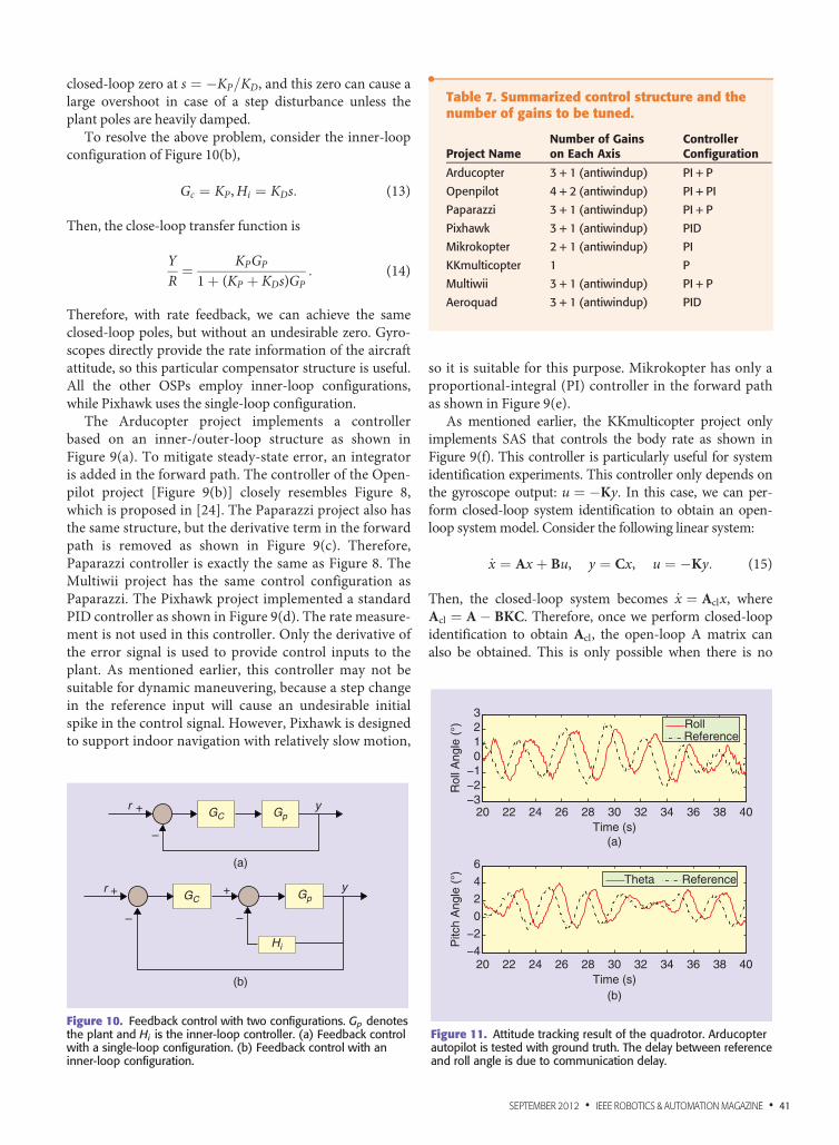
closed-loop zero at s ¼ �KP=KD, and this zero can cause alarge overshoot in case of a step disturbance unless theplant poles are heavily damped.
To resolve the above problem, consider the inner-loopconfiguration of Figure 10(b),
Gc ¼ KP,Hi ¼ KDs: (13)
Then, the close-loop transfer function is
YR¼ KPGP
1þ (KP þ KDs)GP: (14)
Therefore, with rate feedback, we can achieve the sameclosed-loop poles, but without an undesirable zero. Gyro-scopes directly provide the rate information of the aircraftattitude, so this particular compensator structure is useful.All the other OSPs employ inner-loop configurations,while Pixhawk uses the single-loop configuration.
The Arducopter project implements a controllerbased on an inner-/outer-loop structure as shown inFigure 9(a). To mitigate steady-state error, an integratoris added in the forward path. The controller of the Open-pilot project [Figure 9(b)] closely resembles Figure 8,which is proposed in [24]. The Paparazzi project also hasthe same structure, but the derivative term in the forwardpath is removed as shown in Figure 9(c). Therefore,Paparazzi controller is exactly the same as Figure 8. TheMultiwii project has the same control configuration asPaparazzi. The Pixhawk project implemented a standardPID controller as shown in Figure 9(d). The rate measure-ment is not used in this controller. Only the derivative ofthe error signal is used to provide control inputs to theplant. As mentioned earlier, this controller may not besuitable for dynamic maneuvering, because a step changein the reference input will cause an undesirable initialspike in the control signal. However, Pixhawk is designedto support indoor navigation with relatively slow motion,
so it is suitable for this purpose. Mikrokopter has only aproportional-integral (PI) controller in the forward pathas shown in Figure 9(e).
As mentioned earlier, the KKmulticopter project onlyimplements SAS that controls the body rate as shown inFigure 9(f). This controller is particularly useful for systemidentification experiments. This controller only depends onthe gyroscope output: u ¼ �Ky. In this case, we can per-form closed-loop system identification to obtain an open-loop systemmodel. Consider the following linear system:
_x ¼ Ax þ Bu, y ¼ Cx, u ¼ �Ky: (15)
Then, the closed-loop system becomes _x ¼ Aclx, whereAcl ¼ A� BKC. Therefore, once we perform closed-loopidentification to obtain Acl, the open-loop A matrix canalso be obtained. This is only possible when there is no
•Table 7. Summarized control structure and thenumber of gains to be tuned.
Project NameNumber of Gainson Each Axis
ControllerConfiguration
Arducopter 3 + 1 (antiwindup) PI + P
Openpilot 4 + 2 (antiwindup) PI + PI
Paparazzi 3 + 1 (antiwindup) PI + P
Pixhawk 3 + 1 (antiwindup) PID
Mikrokopter 2 + 1 (antiwindup) PI
KKmulticopter 1 P
Multiwii 3 + 1 (antiwindup) PI + P
Aeroquad 3 + 1 (antiwindup) PID
20 22 24 26 28 30 32 34 36 38 40−3−2−1
0123
Time (s)(a)
(b)
20 22 24 26 28 30 32 34 36 38 40Time (s)
Rol
l Ang
le (
°) RollReference
−4
−2
0
2
4
6
Pitc
h A
ngle
(°) Theta Reference
Figure 11. Attitude tracking result of the quadrotor. Arducopterautopilot is tested with ground truth. The delay between referenceand roll angle is due to communication delay.
(a)
(b)
GC
GC Gp
Gpy
y
Hi
r +
r + +
–
–
–
Figure 10. Feedback control with two configurations. Gp denotesthe plant and Hi is the inner-loop controller. (a) Feedback controlwith a single-loop configuration. (b) Feedback control with aninner-loop configuration.
SEPTEMBER 2012 • IEEE ROBOTICS & AUTOMATION MAGAZINE • 41
integrator involved and K is fully known, which is notalways the case for typical quadrotors in the market.
Controller ParametersControl structure and the number of gains to be tunedin each project are shown in Table 7. KKmulticopter isthe simplest one, which has only one gain for tuning.Among many controller configurations, PI+P is domi-nant. P is for the inner loop (rate feedback), and PI isfor the forward attitude error compensation.
Controller EvaluationWe have constructed quadrotors using five different auto-pilots among mentioned OSPs: the Arducopter, Paparazzi,Mikrokopter, KKmulticopter, and Multiwii. Among these
projects, Arducopter, Paparazzi, and Multiwii share thesame controller composition as shown in Table 7. Forqualitative evaluation, we mount markers on a quadrotorto acquire ground-truth data from the Vicon system. Thedesired angle is transmitted to the Arducopter-based quad-rotor while quadrotor attitude from the Vicon and thetransmitted commands are recorded simultaneously. Thesatisfactory attitude tracking result is shown in Figure 11.The delay is due to RC signal processing.
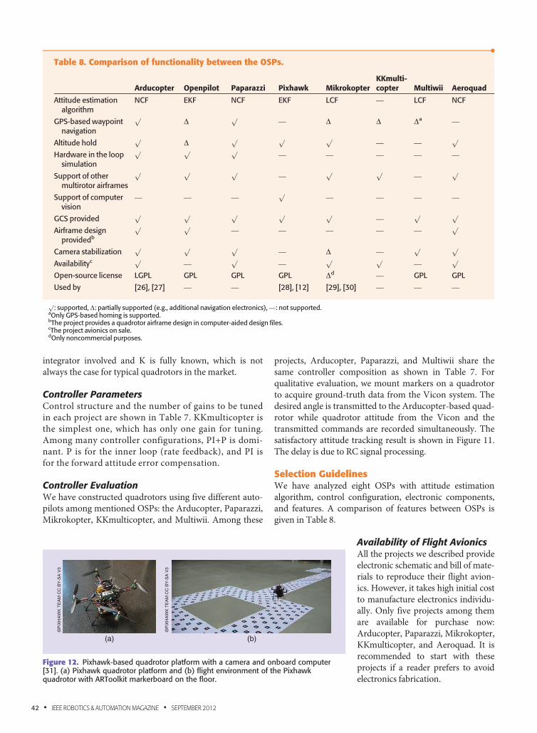
Selection GuidelinesWe have analyzed eight OSPs with attitude estimationalgorithm, control configuration, electronic components,and features. A comparison of features between OSPs isgiven in Table 8.
Availability of Flight AvionicsAll the projects we described provideelectronic schematic and bill of mate-rials to reproduce their flight avion-ics. However, it takes high initial costto manufacture electronics individu-ally. Only five projects among themare available for purchase now:Arducopter, Paparazzi, Mikrokopter,KKmulticopter, and Aeroquad. It isrecommended to start with theseprojects if a reader prefers to avoidelectronics fabrication.
•Table 8. Comparison of functionality between the OSPs.
Arducopter Openpilot Paparazzi Pixhawk MikrokopterKKmulti-copter Multiwii Aeroquad
Attitude estimationalgorithm
NCF EKF NCF EKF LCF — LCF NCF
GPS-based waypointnavigation
pD
p— D D Da —
Altitude holdp
Dp p p
— —p
Hardware in the loopsimulation
p p p— — — — —
Support of othermultirotor airframes
p p p—
p p—
p
Support of computervision
— — —p
— — — —
GCS providedp p p p p
—p p
Airframe designprovidedb
p p— — — — —
p
Camera stabilizationp p p
— D —p p
Availabilityc p—
p—
p p—
p
Open-source license LGPL GPL GPL GPL Dd — GPL GPL
Used by [26], [27] — — [28], [12] [29], [30] — — —
p: supported, D: partially supported (e.g., additional navigation electronics), —: not supported.
aOnly GPS-based homing is supported.bThe project provides a quadrotor airframe design in computer-aided design files.cThe project avionics on sale.dOnly noncommercial purposes.
(a) (b)
©P
IXH
AW
K T
EA
M C
C B
Y-S
A V
3
©P
IXH
AW
K T
EA
M C
C B
Y-S
A V
3
Figure 12. Pixhawk-based quadrotor platform with a camera and onboard computer[31]. (a) Pixhawk quadrotor platform and (b) flight environment of the Pixhawkquadrotor with ARToolkit markerboard on the floor.
42 • IEEE ROBOTICS & AUTOMATION MAGAZINE • SEPTEMBER 2012
Attitude Estimation Algorithm DevelopmentFor attitude estimation tests, Arducopter and Paparazziwill be a good choice. The other projects are equipped withtwo or more gyro chips, which are hard to be calibrated foralignment. Only Arducopter and Paparazzi are equippedwith 6-DoF IMU in a single chip: MPU 6000. The dynamicrange is the best among the accelerometers and gyroscopesas described in Tables 3–6.
Minimalistic ConfigurationAs studied in [23], an open-loop model can be easily iden-tified when control input is fully known and no integratorsexist in a controller as mentioned in the section “AttitudeEstimation Algorithm Development.” Because SAS isimplemented in [23] to identify the open-loop dynamics,KKmulticopter is a good choice to this end. The system issimple to understand and modify because a source codefor attitude control is less than 500 lines in C.
GPS-Based NavigationFor GPS-based outdoor missions (e.g., waypoint naviga-tion and hovering): Arducopter, Openpilot, Paparazzi, orMikrokopter will be a good choice. Only these projectssupport GPS-based navigation. Although Multiwii hasGPS, it only supports a homing capability to move a quad-rotor back to the initial position.
Vision-Based NavigationOnly the Pixhawk project supports vision-based naviga-tion capability. It can synchronize an IMU and a camera inhardware level, which allows tight integration of IMUmeasurements into the computer vision pipeline.
Open-Source Projects in Research
Vision-Based NavigationThe Pixhawk UAV is designed to be a research platformfor computer-vision-based autonomous flight [28]. ThePixhawk team has constructed a localization test setupusing augmented reality ToolKit+(ARToolKitþ). They successfully per-formed waypoint navigation using acamera on the localization test bedas shown in Figure 12.
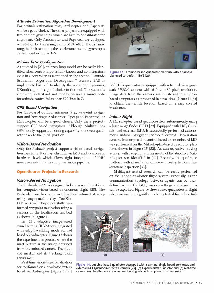
In [26], adaptive image-basedvisual serving (IBVS) was integratedwith adaptive sliding mode controlbased on Arducopter. Figure 13 showsthe experiment in process where theinset picture is the image obtainedfrom the onboard camera. The fidu-cial marker and its tracking resultare shown.
Real-time vision-based localizationwas performed on a quadrotor systembased on Arducopter [Figure 14(a)]
[27]. This quadrotor is equipped with a frontal-view gray-scale USB2.0 camera with 640 3 480 pixel resolution.Image data from the camera are transferred to a single-board computer and processed in a real time [Figure 14(b)]to obtain the vehicle location based on a map createdin advance.
Indoor FlightA Mikrokopter-based quadrotor flew autonomously usinga laser range finder (LRF) [29]. Equipped with LRF, Gum-stix, and external IMU, it successfully performed autono-mous indoor navigation without external localizationsensors. Indoor position control based on an onboard LRFwas performed on the Mikrokopter-based quadrotor plat-form shown in Figure 15 [32]. An autoregressive movingaverage with exogenous terms model of the stabilized Mik-rokopter was identified in [30]. Recently, the quadrotorplatform with shared autonomy was investigated for infra-structure inspection [33].
Multiagent-related research can be easily performedon the indoor quadrotor flight system. Especially, as thecommunication topology between agents can be user-defined within the GCS, various settings and algorithmscan be exploited. Figure 16 shows three quadrotors in flightwhere an auction algorithm is being tested for online task
(a) (b)
Figure 14. Arduino-based quadrotor equipped with a camera, single-board computer, andexternal IMU synchronized with a camera [27]. (a) Experimental quadrotor and (b) real-timevision-based localization is running on the single-board computer on a quadrotor.
Figure 13. Arduino-based quadrotor platform with a camera,designed to perform IBVS [26].
SEPTEMBER 2012 • IEEE ROBOTICS & AUTOMATION MAGAZINE • 43
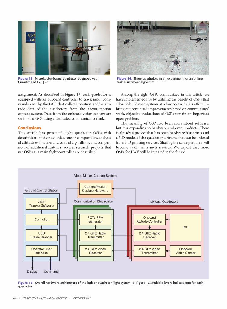
assignment. As described in Figure 17, each quadrotor isequipped with an onboard controller to track input com-mands sent by the GCS that collects position and/or atti-tude data of the quadrotors from the Vicon motioncapture system. Data from the onboard vision sensors aresent to the GCS using a dedicated communication link.
ConclusionsThis article has presented eight quadrotor OSPs withdescriptions of their avionics, sensor composition, analysisof attitude estimation and control algorithms, and compar-ison of additional features. Several research projects thatuse OSPs as a main flight controller are described.
Among the eight OSPs summarized in this article, wehave implemented five by utilizing the benefit of OSPs thatallow to build own systems at a low cost with less effort. Tobring out continued improvements based on communities’work, objective evaluations of OSPs remain an importantopen problem.
The meaning of OSP had been more about software,but it is expanding to hardware and even products. Thereis already a project that has open hardware blueprints anda 3-D model of the quadrotor airframe that can be orderedfrom 3-D printing services. Sharing the same platform willbecome easier with such services. We expect that moreOSPs for UAV will be initiated in the future.
Figure 16. Three quadrotors in an experiment for an onlinetask assignment algorithm.
Figure 15. Mikrokopter-based quadrotor equipped withGumstix and LRF [32].
Vicon Motion Capture System
Communication Electronics
Ground Control Station
ViconTracker Software
ControllerPCTx PPMGenerator
OnboardAttitude Controller
OnboardVision Sensor
Individual Quadrotors
IMU
2.4 GHz RadioTransmitter
2.4 GHz RadioReceiver
2.4 GHz VideoReceiver
2.4 GHz VideoTransmitter
Display Command
USBFrame Grabber
Operator UserInterface
Camera/MotionCapture Hardware
Figure 17. Overall hardware architecture of the indoor quadrotor flight system for Figure 16. Multiple layers indicate one for eachquadrotor.
44 • IEEE ROBOTICS & AUTOMATION MAGAZINE • SEPTEMBER 2012
AcknowledgmentsThis work was supported in part by the National ResearchFoundation of Korea (NRF) grant funded by the Korea gov-ernment (MEST) (nos. 20120000921 and 2012014219), andby the New and Renewable Energy Program of the KoreaInstitute of Energy Technology Evaluation and Planning(KETEP) grant funded by the Korea government Ministry ofKnowledge Economy (no. 20104010100490).
References[1] M. Muller, S. Lupashin, and R. D’Andrea, “Quadrocopter ball
juggling,” in Proc. IEEE/RSJ Int. Conf. Intelligent Robots and Systems
(IROS), Sept. 2011, pp. 5113–5120.
[2] M. Hehn and R. D’Andrea, “A flying inverted pendulum,” in Proc.
IEEE Int. Conf. Robotics and Automation (ICRA), May 2011, pp. 763–770.
[3] V. Kumar. (2012, Feb.). Robots that fly and cooperate, in Proc. TED
Conf. [Online]. Available: http://www.ted.com/talks/lang/en/vijay_
kumar_robots_that_fly_and ,
[4] D. Mellinger, N. Michael, and V. Kumar, “Trajectory generation and
control for precise aggressive maneuvers with quadrotors,” in Proc. Int.
Symp. Experimental Robotics, Dec. 2010.
[5] D. Mellinger, M. Shomin, and V. Kumar, “Control of quadrotors for
robust perching and landing,” in Proc. Int. Powered Lift Conf., Oct. 2010.
[6] S. Lupashin and R. D’Andrea, “Adaptive open-loop aerobatic maneu-
vers for quadrocopters,” in Proc. Int. Federation of Automatic Control
World Cong. (IFAC), 2011, pp. 2600–2606.
[7] Q. Lindsey, D. Mellinger, and V. Kumar, “Construction of cubic structures
with quadrotor teams,” in Proc. Robotics: Science and Systems, June 2011.
[8] P. E. I. Pounds, “Design, construction and control of a large quadrotor
micro air vehicle,” Ph.D. dissertation, Australian National Univ., 2007.
[9] N. Guenard, T. Hamel, and R. Mahony, “A practical visual servo con-
trol for an unmanned aerial vehicle,” IEEE Trans. Robot., vol. 24, no. 2,
pp. 331–340, Apr. 2008.
[10] S. Bouabdallah and R. Siegwart, “Towards intelligent miniature fly-
ing robots,” in Proc. Field and Service Robotics, 2006, pp. 429–440.
[11] G. Hoffmann, D. Rajnarayan, S. Waslander, D. Dostal, J. Jang,
and C. Tomlin, “The stanford testbed of autonomous rotorcraft for
multi agent control (STARMAC),” in Proc. Digital Avionics Systems
Conf., 2004, vol. 2, pp. 12.E.4–121.10.
[12] L. Meier, P. Tanskanen, F. Fraundorfer, and M. Pollefeys,
“PIXHAWK: A system for autonomous flight using onboard computer
vision,” in Proc. ICRA, May 2011, pp. 2992–2997.
[13] P. Brisset, A. Drouin, M. Gorraz, P. Huard, and J. Tyler, “The papar-
azzi solution,” in Proc. Micro Aerial Vehicle, Sandestin, Florida, 2006.
[14] Free Software Foundation, Inc. (2007, June 29). GNU general public
license [Online]. Available: http://www.gnu.org/copyleft/gpl.html.
[15] S. Cousins, B. Gerkey, K. Conley, and W. Garage, “Sharing software
with ROS,” IEEE Robot. Automat. Mag., vol. 17, no. 2, pp. 12–14, June 2010.
[16] Free Software Foundation, Inc. (2007, June 29). GNU lesser GPL
[Online]. Available: http://www.gnu.org/licenses/lgpl.html.
[17] L. Heng, L. Meier, P. Tanskanen, F. Fraundorfer, and M. Pollefeys,
“Autonomous obstacle avoidance and maneuvering on a vision-guided
MAV using on-board processing,” in Proc. ICRA, May 2011, pp. 2472–2477.
[18] G. Lee, M. Achtelik, F. Fraundorfer, M. Pollefeys, and R. Siegwart,
“Benchmarking tool for mav visual pose estimation,” in Proc. Int. Conf.
Control, Automation, Robotics and Vision, 2010, pp. 1541–1546.
[19] G. H. Lee, F. Fraundorfer, and M. Pollefeys, “MAV visual SLAM
with plane constraint,” in Proc. ICRA, May 2011, pp. 3139–3144.
[20] D. Simon, Optimal State Estimation: Kalman, H [infinity] and Non-
linear Approaches. Hoboken, NJ: Wiley, 2006.
[21] A. Pascoal, I. Kaminer, and P. Oliveira, “Navigation system design
using time-varying complementary filters,” IEEE Trans. Aerosp. Electron.
Syst., vol. 36, no. 4, pp. 1099–1114, 2000.
[22] R. Mahony, T. Hamel, and J.-M. Pflimlin, “Nonlinear complemen-
tary filters on the special orthogonal group,” IEEE Trans. Automat.
Contr., vol. 53, no. 5, pp. 1203–1218, June 2008.
[23] D. S. Miller, “Open loop system identification of a micro quadrotor
helicopter from closed loop data,” Master’s thesis, Univ. Maryland, Col-
lege Park, 2011.
[24] F. Lewis and B. Stevens, Aircraft Control and Simulation. Hoboken,
NJ: Wiley, 2003.
[25] R. Nelson, Flight Stability and Automatic Control. New York:
McGraw-Hill, 1989.
[26] D. Lee, H. Lim, H. J. Kim, and Y. Kim, “Adaptive image-based visual
servoing for an under-actuated quadrotor system,” AIAA J. Guid. Control
Dyn., vol. 35, no. 4, pp. 1335–1353.
[27] H. Lim, S. N. Sinha, M. Cohen, and M. Uyttendaele, “Real-time
image-based 6-dof localization in large-scale environments,” in Proc.
IEEE Conf. Computer Vision and Pattern Recognition (CVPR), June 2012,
pp. 1043–1050.
[28] L. Meier, P. Tanskanen, L. Heng, G. Lee, F. Fraundorfer, and M. Pol-
lefeys, “PIXHAWK: A micro aerial vehicle design for autonomous flight
using onboard computer vision,” Auton. Robots, vol. 33, no. 1, pp. 21–39,
2012.
[29] S. Grzonka, G. Grisetti, and W. Burgard, “A fully autonomous
indoor quadrotor,” IEEE Trans. Robot., vol. 28, no. 99, pp. 1–11, 2012.
[30] I. Sa and P. Corke, “System identification, estimation and control for
a cost effective open-source quadcopter,” in Proc. IEEE Int. Conf. Robotics
and Automation (ICRA), 2012, pp. 2202–2209.
[31] ETHZ PixhawkMAV [Online]. Available: https://pixhawk.ethz.ch.
[32] I. Sa and P. Corke, “Estimation and control for an open-source
quadcopter,” in Proc. Australian Conf. Robotics and Automation, 2011.
[33] I. Sa and P. Corke, “Vertical infrastructure inspection using a quad-
copter and shared autonomy control,” in Proc. Int. Conf. Field and Service
Robotics, 2012.
Hyon Lim, Department of Mechanical and AerospaceEngineering, Seoul National University, Seoul 151-742,South Korea. E-mail: [email protected].
Jaemann Park, Department of Mechanical and AerospaceEngineering, Seoul National University, Seoul 151-742,South Korea. E-mail: [email protected].
Daewon Lee, Department of Mechanical and AerospaceEngineering, Seoul National University, Seoul 151-742,South Korea. E-mail: [email protected].
H.J. Kim, Department of Mechanical and Aerospace Engi-neering, Seoul National University, Seoul 151-742, SouthKorea. E-mail: [email protected].
SEPTEMBER 2012 • IEEE ROBOTICS & AUTOMATION MAGAZINE • 45