build your own clone confidence booster kit...
TRANSCRIPT

Build Your Own Clone Confidence Booster
Kit Instructions
Warranty: BYOC, Inc. guarantees that your kit will be complete and that all parts and components will arrive as described, functioning and free of defect. Soldering, clipping, cutting, stripping, or using any of the components in any way voids this guarantee. BYOC, Inc. guarantees that the instructions for your kit will be free of any majors errors that would cause you to permanently damage any components in your kit, but does not guarantee that the instructions will be free of typos or minor errors. BYOC, Inc. does not warranty the completed pedal as a whole functioning unit, nor do we warranty any of the individual parts once they have been used. If you have a component that is used, but feel it was defective prior to you using it, we reserve the right to determine whether or not the component was faulty upon arrival. Please direct all warranty issues to: [email protected] This would include any missing parts issues. Return: BYOC, Inc. accepts returns and exchanges on all products for any reason, as long as they are unused. We do not accept partial kit returns. Returns and exchanges are for the full purchase price less the cost of shipping and/or any promotional pricing. Return shipping is the customer’s responsibility. This responsibility not only includes the cost of shipping, but accountability of deliver as well. Please contact [email protected] to receive a return authorization before mailing. Tech Support: BYOC, Inc. makes no promises or guarantees that you will successfully complete your kit in a satisfactory manor. Nor does BYOC, Inc. promise or guarantee that you will

receive any technical support. Purchasing a product from BYOC, Inc. does not entitle you to any amount of technical support. BYOC, Inc. does not promise or guarantee that any technical support you may receive will be able to resolve any or all issues you may be experiencing. That being said, we will do our best to help you as much as we can. Our philosophy at BYOC is that we will help you only as much as you are willing to help yourself. We have a wonderful and friendly DIY discussion forum with an entire section devoted to the technical support and modifications of BYOC kits. www.byocelectronics.com/board When posting a tech support thread on the BYOC forum, please post it in the correct lounge, and please title your thread appropriately. If everyone titles their threads “HELP!” then it makes it impossible for the people who are helping you to keep track of your progress. A very brief description of your specific problem will do. It will also make it easier to see if someone else is having or has had the same problem as you. The question you are about to ask may already be answered. Here is a list of things that you should include in the body of your tech support thread: 1. A detailed explanation of what the problem is. (more than, “It doesn’t work, help”) 2. Pic of the topside of your PCB. 3. Pic of the underside of your PCB. 4. Pic that clearly shows your footswitch/jack wiring and the wires going to the PCB 5. A pic that clearly shows your wiring going from the PCB to the pots and any other switches (only if your kit has non-PC mounted pots and switches) 6. Is bypass working? 7. Does the LED come on? 8. If you answered yes to 6 and 7, what does the pedal do when it is in the "on" position? 9. Battery or adapter (if battery, is it good? If adapter, what type?) Also, please only post photos that are in focus.
Copyrights: All material in this document is copyrighted 2017 by BYOC, Inc.

Confidence Booster Kit Instruction Index
Parts Checklist……………………………………….page 4 Populating the Circuit Board……………………….page 7 Wiring………………………………………………..page 13 Schematic……………………………………………page 18
Parts Checklist for the Confidence Booster Kit Resistors 1% metal film has a light blue body and 5 bands. 5% carbon film has a light brown body and 4 bands. Your kit may come with one or both types. 1 - 360 Ohm (Orange/Blue/Black/Black/Brown) or (Orange/Blue/Brown/Gold) or 390 Ohm (Orange/White/Black/Black/Brown) or (Orange/White/Black/Gold) 1 - 10k (Brown/Black/Black/Red/Brown) or (Brown/Black/Orange/Gold) 1 - 100k (Brown/Black/Black/Orange/Brown) or (Brown/Black/Yellow/Gold) 1 - 1M (Brown/Black/Black/Yellow/Brown) or (Brown/Black/Green/Gold) 2 - 2M2 (Red/Red/Black/Yellow/Brown) or (Red/Red/Green/Gold) Capacitors: 3 - 100n/.1uF Film cap - These may be green or red in color. The code on the body may consist of various alphanumeric characters, but in the center of the code will be the numbers “104”. So for example, your cap may read ‘2p104k’. The characters refer to model and tolerance. The inner ‘104’ is the important code that tells you the capacitor value is 0.1 microfarads 1 - 100uF Aluminum Electrolytic Your kit may actually come with anything from 1uf - 220uf. The aluminum electrolytic capacitor will be shaped like a can. It will have one lead that is longer. This is the positive lead. The shorter lead is the negative lead and there will also be a stripe or some sort of marking along the negative side. Transistors: 1 - 2N5088 Your kit may actually come with a 2N3904, MPSA18, or any other NPN silicon transistor with an EBC pinout. Diodes: 1 - 1N4001 (Black with a silver stripe) IC: 1 - 4558 or similar Dual Op-amp Potentiometers: 1 - 100k Trimpot Your kit may come with anything from 10k - 500k. Hardware: 1 - Confidence Booster PCB 2 - Enclosed Jacks 1 - Battery Snap Hook-up wire

Understanding Resistors
When reading 4 band resistor code, you take the first 2 bands at face value. The 3rd band tells you how many zeros to add to the end. And the 4th band tells you the tolerance of the resistor.
What is tolerance? Tolerance means how close the component will likely be to its intended value. So a 10k resistor with a 5% tolerance could actually be anywhere between 9.5K - 10.5k where as a 10k resistor with a 1% tolerance will be anywhere between 9.9k and 10.1k.
The lower the tolerance the more accurate the component will be. With resistors, a BROWN band = 1%, a GOLD band = 5%. There are also Silver =10% and red = 2%, but you will rarely see those this day and age. The only time you are likely to see 10% is if you are working with vintage electronics and 2% just aren't used often.
5 band resistor code isn't really much different from 4 band. The first 3 bands are taken at face value. The 4th band tells you how many zeros to add to the end. And the 5th band will tell you the tolerance. You are likely to only see 5 band code on 1% resistors. This is because they are more precise and their advertised values will sometimes go out 2 decimal places, so they need the extra band.

Capacitor values and codes In the world of capacitors, you will most commonly run into two units of
measurement - MicroFarads and PicoFarads. There is a third unit - NanoFarads. This was a common unit 25+ years ago. It is losing popularity, but you will run into it occasionally.
The symbol for Microfarads is “µF”. µ is from the Greek letter “Mµ” with the relation coming from the Greek word ‘mikrós’, which means small. The ‘F’ is for Farad. You will also see “uF” or “mF” as the symbol for microfarads since many text editors don't have a proper µ. From here on out, and in all other BYOC documents, you'll see microfarads referred to as uf.
The symbol for NanoFarad is nF, and the symbol for PicoFarad is pF. Microfarad is the largest unit, nanofarad is the second largest, and picofarad is the smallest.
1uf = 1000nf = 1000000pf 1pf = .001nf = .000001mf From the equations above, you can see that when converting from a larger unit to
a smaller unit, you simply move the decimal point 3 places to the right for each unit of measurement you step down to.
When converting from a smaller unit to a larger unit you simply move the decimal point 3 places to the right for each unit of measurement you step up to.
Capacitor codes
Large value capacitors will usually be in aluminum electrolytic form, medium values in film and small values in ceramic disc. There are other types of capacitors like silver-mica, which is usually only associated with very small values. And tantalum capacitors, which can cover a very broad range of values.
A very common capacitor value is 0.1uF. You will most likely see this in film form. You will most likely see a code on the resistor that reads something like ‘104K´. This is similar to 4 band resistor code. The letter at the end tells you the capacitor's tolerance. K= 10% J= 5%. The ‘104´ portion of the code tells you the actual value. Even though the capacitor is listed as 0.1 microfarad, the code is actually in picofarads. The ‘1’ and the ‘0’ are taken at face value. The ‘4’ tells us how many zeros to put on the end. So the value of the capacitor in picofarads is 100,000pf. Or 100nf. Or 0.1uf.
With smaller values like 47pf for example, you will likely be dealing with ceramic disc capacitors. The code on a 47pf cap would read ‘470´. This is 47 at face value with 0 zeros on the end. 47 picofarads. Where as a 470pf cap would read ³471´ - 47 at face value with 1 zero on the end. 470picofarads. It can get a little confusing at times.
Larger value capacitors, particularly aluminum electrolytics are pretty straightforward. If you have a 100uf aluminum electrolytic cap, most of the time they will just say ‘100µ´ right out.
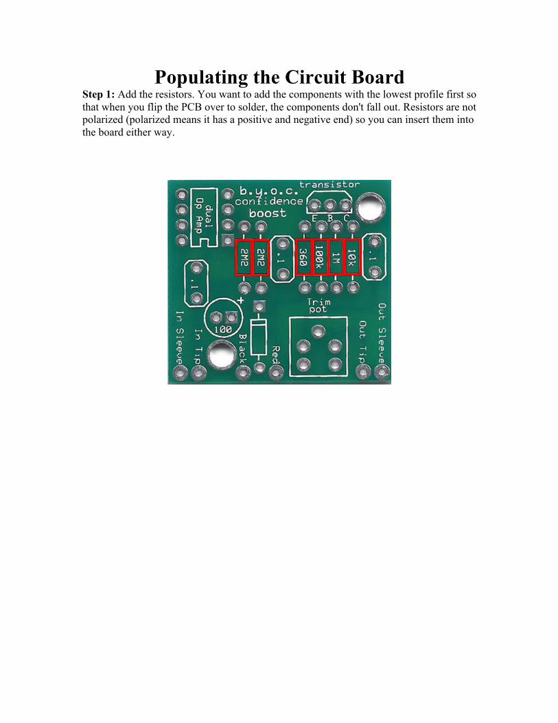
Populating the Circuit Board Step 1: Add the resistors. You want to add the components with the lowest profile first so that when you flip the PCB over to solder, the components don't fall out. Resistors are not polarized (polarized means it has a positive and negative end) so you can insert them into the board either way.

Step 2: Add the diode. The end with the stripe on it is called the cathode. This end goes into the square solder pad and stripe on the diode and stripe on the layout should match up. The other end of the diode is called the anode.

Step 3: Add the Opamp. Op amps come with two markers to help you determine how to orientate the component. The first is a notch in one end of the chip. If your chip has a notch on one end, insert it into the PCB so that it matches up with the notch in the layout. The other marker is a dot in one corner. This dot denotes pin # 1 of the chip. Pin 1 goes into the square soldering pad. Occasionally you will run into chips that have both the notch and dot markers. In this case, always use the notch as the primary marker.

Step 4: Add the trimpot. The trimpot will have 3 leads. The PCB has eyelets for 5 leads. This is so that the PCB can accept a variety of pinout styles. There will only be one way that the trimpot can fit into the PCB.
How to set the trimpot: The trimpot is the output volume control.

Step 5: Add the transistor. Match the curved side of the transistor up with the curve side of the layout. A TO-92 package transistor such as the 2N5088 will have 3 leads - the emitter, base, and collector. They are marked on the PCB with E, B, and C.

Step 6: Add the aluminum electrolytic capacitors. Your kit may come with a value between 1uf and 220uf. Aluminum electrolytic capacitors are polarized. The longer lead goes in the square solder pad.

Step 6: Add the film capacitors. These are not polarized and can go in either direction.

Wiring Your kit may come with a variety of input/output jacks. They are all wired slightly different, but all do the exact same thing. Your kit will usually come with a matching pair, but if your kit comes with a mix, follow the wiring for that jack.


Plugging it in 1. Use a fresh 9v battery. 2. Connect the in jack to your guitar and the out jack to your amp. 3. Use a small screwdriver or similar tool to turn the trimpot. What does this pedal do? Nothing special. When you have the trimpot about half way, you shouldn't hear much of anything. The volume levels should be about the same as if you were to plug your guitar directly into the amp. This is commonly referred to as unity gain. When you turn the trimpot down, it should drop in volume, and when you turn the trimpot up, it should increase in volume. Nothing more. Very simple. We suggest that you visit the BYOC forum board.buildyourownclone.com if you'd like someone to take a look at your build and give you any pointers on areas for improvement. Also, it's best to ask questions first if there is something you are confused about, and the BYOC forum is the place to do it.


Please visit http://byocelectronics.com/board
For any technical support
Copyright 2017 BYOC, Inc.