build a low-cost mid-power launch pad 1 of 7 build a low-cost mid-power launch pad this model rocket...
TRANSCRIPT
Page 1 of 7
BUILD A LOW-COST MID-POWER LAUNCH PAD
This model rocket launch pad will handle mid-power model rockets up to 2 pounds with a ‘G’ engine.
NOTE: These instructions are presented without warranty of any kind. The author is not
responsible for any liability or loss related to the construction and operation of the launch pad.
Remember to follow the National Association of Rocketry’s Safety Code for all model rocket flights.
Considering joining the NAR for member benefits, including insurance: http://www.nar.org/
Parts you will need to purchase The following items are available at most hardware stores and home improvements stores, such as
Lowes, Home Depot, ACE or TrueValue. The total cost should be around $20.
Qty Description 1 1-inch PVC 4-way cross coupler (pipe fits inside all 4 ends)
4 1-inch PVC 45° Elbow couplers (pipe fits inside both ends)
1 10ft x 1-inch PVC Pipe, cut into four 2.5 inch pieces and four ~27.5 inch pieces
1 “Neutral Terminal lug”, Lowes #36512, HomeDepot #527698, or equivalent. There are many types, but make sure it has at least a 1/4" hole for the rod.
2 1/4" Washers, larger outside diameter “fender washers” preferred
1 Steel Rod, 1/4" Dia, 4ft long (preferred) or 3ft long
1 Blast Deflector, "Blank Octagon Electrical Cover", Lowes #113199 or equivalent
1 Roll of ¾” wide masking tape, high stickiness (not “blue tape”)
Other supplies you will need The following items and tools will be used during assembly:
Small container of Gorilla Glue (recommended) or PVC pipe cement (see caution)
A saw to cut the PVC pipe (hack saw or powered sabre saw)
Sandpaper (100 to 200 grit)
Measuring tape (at least 10 ft long)
Pen or pencil (to mark the measurements before cutting the pipe)
Drill with 1/4" drill bit
Flat blade screwdriver, medium sized
Paper towels
Cleaning solution, such as window cleaner or WD-40
CAUTION!
Be careful cutting the PVC pipe. Edges of the plastic pipe may be sharp after cutting.
If using PVC pipe cement, use sufficient ventilation, skin protection, and eye protection.
Use proper procedures for saws and other tools.
Page 2 of 7
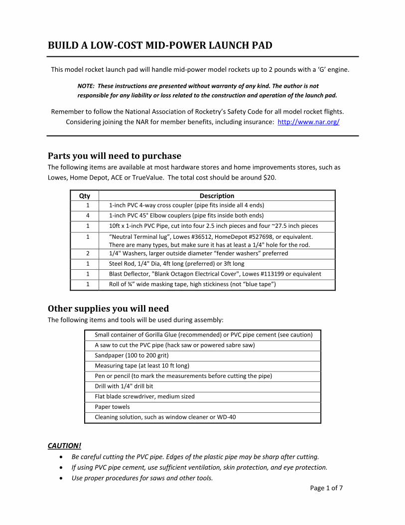
Gather all parts and tools before getting started. The following pictures show the parts and tools required to build the launch pad.
(The 10ft of PVC pipe is shown after cutting the pieces to length.)
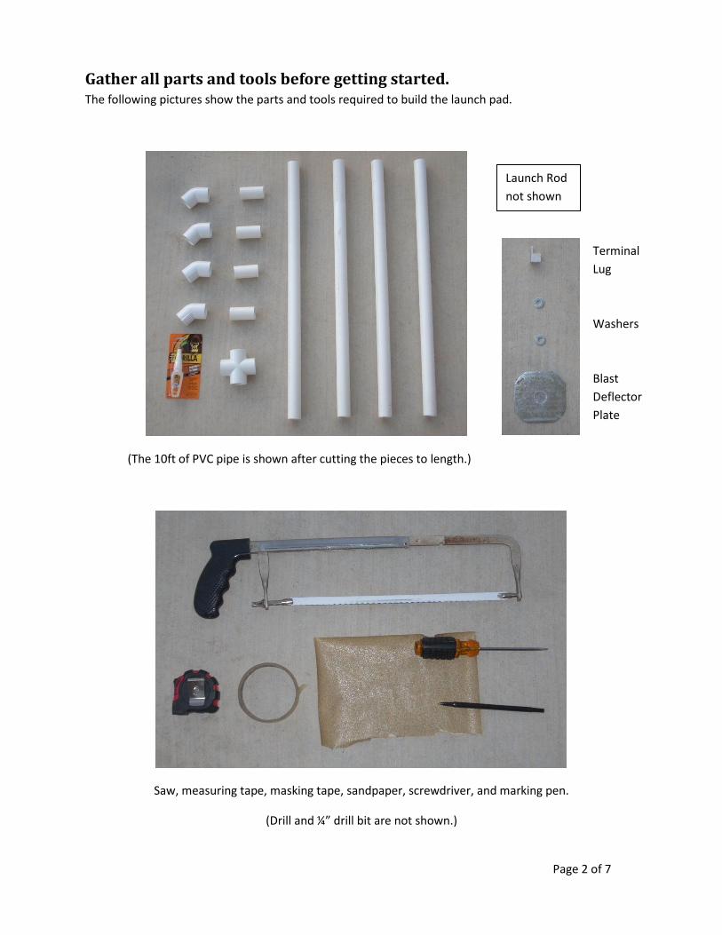
Saw, measuring tape, masking tape, sandpaper, screwdriver, and marking pen.
(Drill and ¼” drill bit are not shown.)
Launch Rod
not shown
Terminal
Lug
Washers
Blast
Deflector
Plate
Page 3 of 7
Cutting the PVC Pipe The 10-foot length of 1” PVC pipe is needed to make the four base-coupling pieces and the four legs.
The long single piece of pipe may be cut into two 5-foot pieces at the store to make it easier to
transport.
Cutting the Coupler Pieces
Cut the 10-foot pipe in half by measuring the full length and dividing by two. The length from
the factory may not be exactly 10 feet! You should have two pieces approximately 5 feet long
each. The exact length is not important but they should be close to the same length.
Cut two 2.5” couplers from each 5-foot piece! This is important because you will be cutting the
remainder of the pipe in half again to form the four legs with equal lengths.
Measure 2.5 inches from one end of the pipe and mark with a line around the pipe.
Cut the pipe as evenly as possible using the hacksaw or the powered sabre saw.
Repeat the measuring and cutting until you have four coupler pieces (two are cut from each 5-
foot piece of pipe).
Using the sandpaper, remove the rough edges from the ends of each coupler piece. Sand the
surface of each coupler piece lightly (this will help the glue adhere better).
Cutting the Leg Pieces
Take one of the 5-foot long pieces of pipe, measure its length and divide by two. Mark the pipe
at its midpoint. Each leg should be about 27.5 inches (or slightly less), depending on previous cut
widths.
Repeat the midpoint cut for the other 5-foot piece. You now have four legs for the launch pad.
Try to make sure each leg is about the same length (within about ¼ of an inch).
Sand the ends to remove the rough edges. Do not sand the outer surfaces.
You should now have all the parts cut as shown on the previous page.
Page 4 of 7
Assembling the Base of the Launch Pad The base of the pad if formed by the “X” shaped PCV cross piece, the four elbows, and the four coupler
pieces you cut during the previous step.
It is important to glue only the coupler pieces as instructed!
Do NOT glue the joints that connect the elbows to the pad legs!
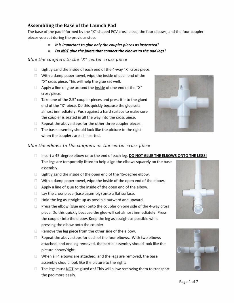
Glue the couplers to the “X” center cross piece
Lightly sand the inside of each end of the 4-way “X” cross piece.
With a damp paper towel, wipe the inside of each end of the
“X” cross piece. This will help the glue set well.
Apply a line of glue around the inside of one end of the “X”
cross piece.
Take one of the 2.5” coupler pieces and press it into the glued
end of the “X” piece. Do this quickly because the glue sets
almost immediately! Push against a hard surface to make sure
the coupler is seated in all the way into the cross piece.
Repeat the above steps for the other three coupler pieces.
The base assembly should look like the picture to the right
when the couplers are all inserted.
Glue the elbows to the couplers on the center cross piece
Insert a 45-degree elbow onto the end of each leg. DO NOT GLUE THE ELBOWS ONTO THE LEGS!
The legs are temporarily fitted to help align the elbows squarely on the base
assembly.
Lightly sand the inside of the open end of the 45-degree elbow.
With a damp paper towel, wipe the inside of the open end of the elbow.
Apply a line of glue to the inside of the open end of the elbow.
Lay the cross piece (base assembly) onto a flat surface.
Hold the leg as straight up as possible outward and upward.
Press the elbow (glue end) onto the coupler on one side of the 4-way cross
piece. Do this quickly because the glue will set almost immediately! Press
the coupler into the elbow. Keep the leg as straight as possible while
pressing the elbow onto the coupler.
Remove the leg piece from the other side of the elbow.
Repeat the above steps for each of the four elbows. With two elbows
attached, and one leg removed, the partial assembly should look like the
picture above/right.
When all 4 elbows are attached, and the legs are removed, the base
assembly should look like the picture to the right:
The legs must NOT be glued on! This will allow removing them to transport
the pad more easily.
Page 5 of 7
Attaching the launch rod to the base assembly The steel rod is the guide for the rocket during its initial moments of flight. It is important that the rod is
firmly attached to the pad such that it doesn’t come out when the rocket lifts off! It is also important
that the rod is pointing straight without wobbling around. Do not bend the launch rod!
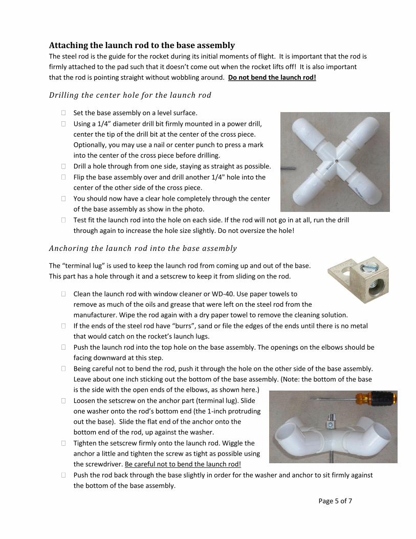
Drilling the center hole for the launch rod
Set the base assembly on a level surface.
Using a 1/4” diameter drill bit firmly mounted in a power drill,
center the tip of the drill bit at the center of the cross piece.
Optionally, you may use a nail or center punch to press a mark
into the center of the cross piece before drilling.
Drill a hole through from one side, staying as straight as possible.
Flip the base assembly over and drill another 1/4" hole into the
center of the other side of the cross piece.
You should now have a clear hole completely through the center
of the base assembly as show in the photo.
Test fit the launch rod into the hole on each side. If the rod will not go in at all, run the drill
through again to increase the hole size slightly. Do not oversize the hole!
Anchoring the launch rod into the base assembly
The “terminal lug” is used to keep the launch rod from coming up and out of the base.
This part has a hole through it and a setscrew to keep it from sliding on the rod.
Clean the launch rod with window cleaner or WD-40. Use paper towels to
remove as much of the oils and grease that were left on the steel rod from the
manufacturer. Wipe the rod again with a dry paper towel to remove the cleaning solution.
If the ends of the steel rod have “burrs”, sand or file the edges of the ends until there is no metal
that would catch on the rocket’s launch lugs.
Push the launch rod into the top hole on the base assembly. The openings on the elbows should be
facing downward at this step.
Being careful not to bend the rod, push it through the hole on the other side of the base assembly.
Leave about one inch sticking out the bottom of the base assembly. (Note: the bottom of the base
is the side with the open ends of the elbows, as shown here.)
Loosen the setscrew on the anchor part (terminal lug). Slide
one washer onto the rod’s bottom end (the 1-inch protruding
out the base). Slide the flat end of the anchor onto the
bottom end of the rod, up against the washer.
Tighten the setscrew firmly onto the launch rod. Wiggle the
anchor a little and tighten the screw as tight as possible using
the screwdriver. Be careful not to bend the launch rod!
Push the rod back through the base slightly in order for the washer and anchor to sit firmly against
the bottom of the base assembly.
Page 6 of 7
Retaining the upper side of the launch rod on the base assembly
The bottom of the launch rod is kept from coming back out of the hole using the anchor attached in the
previous step. Now you will need to keep the rod from sliding back down through the hole.
Slide the other washer over the top end of the launch rod and position it against the top of the
base assembly.
Make sure the anchor is pressed firmly against the bottom of the base assembly by pulling the
rod upward while holding the base. Do not stress or bend the launch rod!
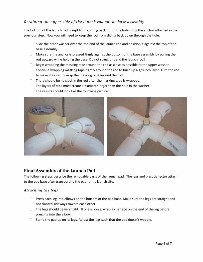
Begin wrapping the masking take around the rod as close as possible to the upper washer.
Continue wrapping masking tape tightly around the rod to build up a 1/8 inch layer. Turn the rod
to make it easier to wrap the masking tape around the rod.
There should be no slack in the rod after the masking tape is wrapped.
The layers of tape must create a diameter larger than the hole in the washer.
The results should look like the following picture:
Final Assembly of the Launch Pad The following steps describe the removable parts of the launch pad. The legs and blast deflector attach
to the pad base after transporting the pad to the launch site.
Attaching the legs
Press each leg into elbows on the bottom of the pad base. Make sure the legs are straight and
not slanted sideways toward each other.
The legs should be very tight. If one is loose, wrap some tape on the end of the leg before
pressing into the elbow.
Stand the pad up on its legs. Adjust the legs such that the pad doesn’t wobble.
Page 7 of 7
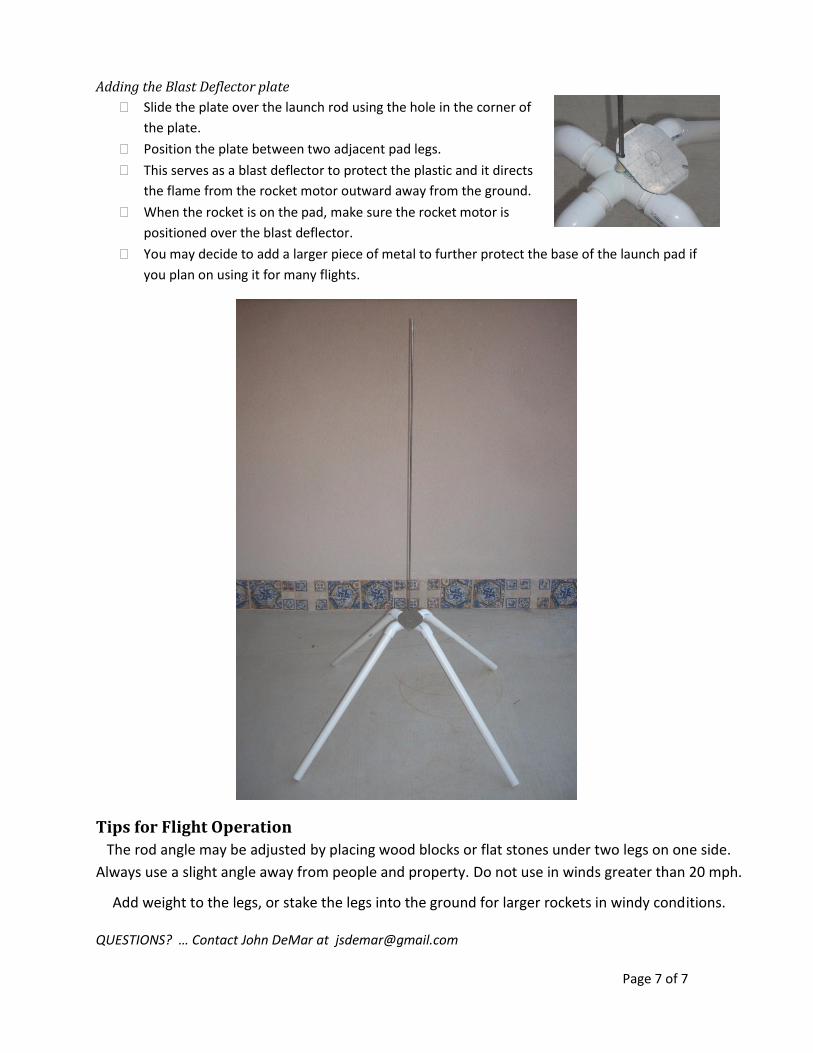
Adding the Blast Deflector plate
Slide the plate over the launch rod using the hole in the corner of
the plate.
Position the plate between two adjacent pad legs.
This serves as a blast deflector to protect the plastic and it directs
the flame from the rocket motor outward away from the ground.
When the rocket is on the pad, make sure the rocket motor is
positioned over the blast deflector.
You may decide to add a larger piece of metal to further protect the base of the launch pad if
you plan on using it for many flights.
Tips for Flight Operation
The rod angle may be adjusted by placing wood blocks or flat stones under two legs on one side.
Always use a slight angle away from people and property. Do not use in winds greater than 20 mph.
Add weight to the legs, or stake the legs into the ground for larger rockets in windy conditions.
QUESTIONS? … Contact John DeMar at [email protected]