bucher products available from hydratec products available from hydratec 12months ... thread is...
TRANSCRIPT
Unbiased Unbranded Reliable
DZE ELECTRONIC PRESSURE SWITCH for detection of overload per EN 81−2 featuring two adjustable switching points
BUCHER PRODUCTS AVAILABLE FROM HYDRATEC
12monthson-site warrantyAll our work comes with the assurance that any callbacks are covered including parts and labour
Our engineers are certified First Aiders so can even work when the site First Aider is absent
2. GENERAL DESCRIPTION
• Electronic pressure switch for detection of overload on a hydraulic lift as per EN81−2, Section 14.2.5.2
• Two individually adjustable switching points (e.g. min. pressure/max. pressure)
• Digital display of current pressure and switching point
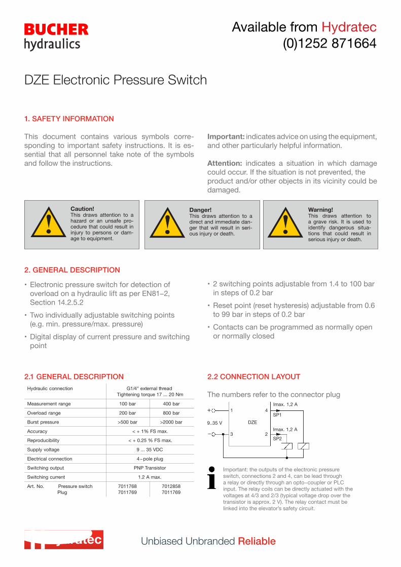
2.1 GENERAL DESCRIPTION 2.2 CONNECTION LAYOUT
The numbers refer to the connector plug
1. SAFETY INFORMATION
This document contains various symbols corre-sponding to important safety instructions. It is es-sential that all personnel take note of the symbols and follow the instructions.
Important: indicates advice on using the equipment, and other particularly helpful information.
Attention: indicates a situation in which damage could occur. If the situation is not prevented, theproduct and/or other objects in its vicinity could be damaged.
Unbiased Unbranded Reliable
Available from Hydratec (0)1252 871664
DZE Electronic Pressure Switch
Caution!This draws attention to a hazard or an unsafe pro-cedure that could result in injury to persons or dam-age to equipment.
Danger!This draws attention to a direct and immediate dan-ger that will result in seri-ous injury or death.
Warning!This draws attention to a grave risk. It is used to identify dangerous situa-tions that could result in serious injury or death.
• 2 switching points adjustable from 1.4 to 100 bar in steps of 0.2 bar
• Reset point (reset hysteresis) adjustable from 0.6 to 99 bar in steps of 0.2 bar
• Contacts can be programmed as normally open or normally closed
Important: the outputs of the electronic pressure switch, connections 2 and 4, can be lead througha relay or directly through an opto−coupler or PLC input. The relay coils can be directly actuated with the voltages at 4/3 and 2/3 (typical voltage drop over the transistor is approx. 2 V). The relay contact must be linked into the elevator’s safety circuit.
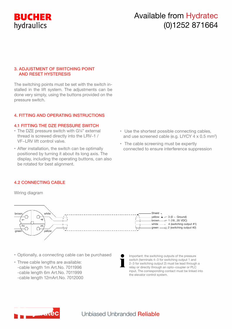
4.2 CONNECTING CABLE
Wiring diagram
3. ADJUSTMENT OF SWITCHING POINT AND RESET HYSTERESIS
The switching points must be set with the switch in-stalled in the lift system. The adjustments can be done very simply, using the buttons provided on thepressure switch.
4. FITTING AND OPERATING INSTRUCTIONS
4.1 FITTING THE DZE PRESSURE SWITCH• The DZE pressure switch with G¼” external
thread is screwed directly into the LRV−1 / VF−LRV lift control valve.
• After installation, the switch can be optimally positioned by turning it about its long axis. The display, including the operating buttons, can also be rotated for best alignment.
• Optionally, a connecting cable can be purchased• Three cable lengths are available:
-cable length 1m Art.No. 7011996 -cable length 6m Art.No. 7011999 -cable length 12mArt.No. 7012000
Unbiased Unbranded Reliable
Available from Hydratec (0)1252 871664
Important: the switching outputs of the pressure switch (terminals 4−3 for switching output 1 and2−3 for switching output 2) must be lead through a relay or directly through an opto−coupler or PLCinput. The corresponding contact must be linked into the elevator control system.
• Use the shortest possible connecting cables, and use screened cable (e.g. LIYCY 4 x 0.5 mm2)
• The cable screening must be expertly connected to ensure interference suppression
Unbiased Unbranded Reliable
Available from Hydratec (0)1252 871664
4.3 OPERATION AND ADJUSTMENT OF THE DZE PRESSURE SWITCH
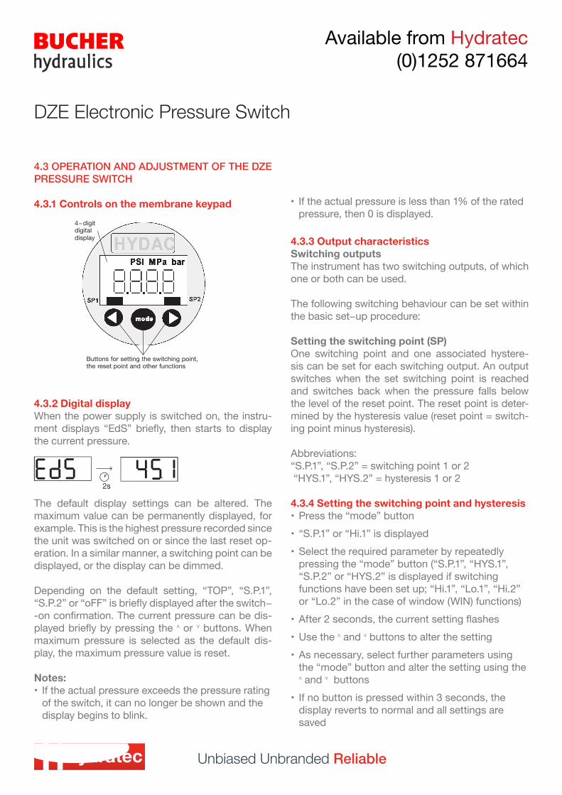
4.3.1 Controls on the membrane keypad
DZE Electronic Pressure Switch
4.3.2 Digital displayWhen the power supply is switched on, the instru-ment displays “EdS” briefly, then starts to display the current pressure.
4.3.3 Output characteristicsSwitching outputsThe instrument has two switching outputs, of which one or both can be used.
The following switching behaviour can be set within the basic set−up procedure:
Setting the switching point (SP)One switching point and one associated hystere-sis can be set for each switching output. An output switches when the set switching point is reached and switches back when the pressure falls below the level of the reset point. The reset point is deter-mined by the hysteresis value (reset point = switch-ing point minus hysteresis).
Abbreviations:“S.P.1”, “S.P.2” = switching point 1 or 2 “HYS.1”, “HYS.2” = hysteresis 1 or 2
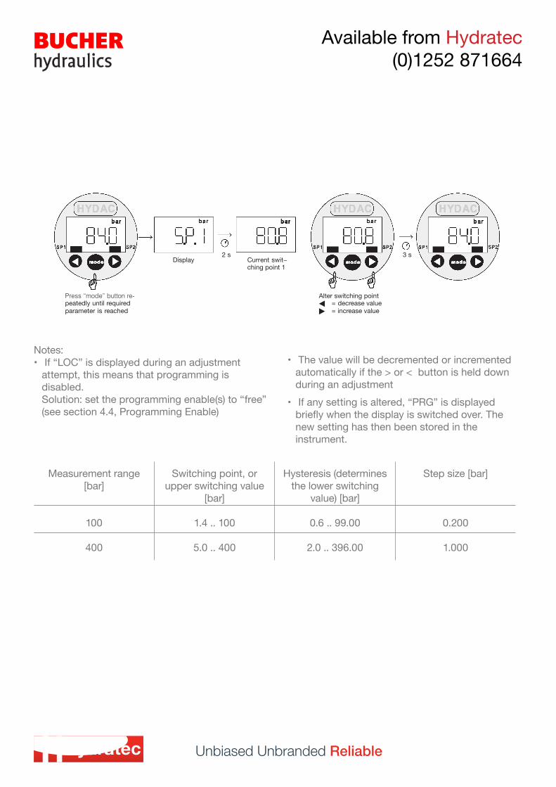
4.3.4 Setting the switching point and hysteresis• Press the “mode” button• “S.P.1” or “Hi.1” is displayed• Select the required parameter by repeatedly
pressing the “mode” button (“S.P.1”, “HYS.1”, “S.P.2” or “HYS.2” is displayed if switching functions have been set up; “Hi.1”, “Lo.1”, “Hi.2” or “Lo.2” in the case of window (WIN) functions)
• After 2 seconds, the current setting flashes• Use the ˄ and ˅ buttons to alter the setting• As necessary, select further parameters using
the “mode” button and alter the setting using the ˄ and ˅ buttons
• If no button is pressed within 3 seconds, the display reverts to normal and all settings are saved
The default display settings can be altered. The maximum value can be permanently displayed, for example. This is the highest pressure recorded sincethe unit was switched on or since the last reset op-eration. In a similar manner, a switching point can be displayed, or the display can be dimmed.
Depending on the default setting, “TOP”, “S.P.1”, “S.P.2” or “oFF” is briefly displayed after the switch− -on confirmation. The current pressure can be dis-played briefly by pressing the ˄ or ˅ buttons. When maximum pressure is selected as the default dis-play, the maximum pressure value is reset.
Notes:• If the actual pressure exceeds the pressure rating
of the switch, it can no longer be shown and the display begins to blink.
• If the actual pressure is less than 1% of the rated pressure, then 0 is displayed.
Unbiased Unbranded Reliable
Available from Hydratec (0)1252 871664
Notes:• If “LOC” is displayed during an adjustment
attempt, this means that programming is disabled. Solution: set the programming enable(s) to “free” (see section 4.4, Programming Enable)
• The value will be decremented or incremented automatically if the > or < button is held down during an adjustment
• If any setting is altered, “PRG” is displayed briefly when the display is switched over. The new setting has then been stored in the instrument.
Measurement range [bar]
Switching point, or upper switching value
[bar]
Hysteresis (determines the lower switching
value) [bar]
Step size [bar]
100 1.4 .. 100 0.6 .. 99.00 0.200
400 5.0 .. 400 2.0 .. 396.00 1.000
Unbiased Unbranded Reliable
Available from Hydratec (0)1252 871664
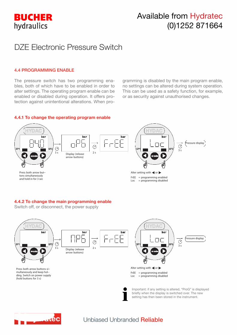
4.4 PROGRAMMING ENABLE
The pressure switch has two programming ena-bles, both of which have to be enabled in order to alter settings. The operating program enable can be enabled or disabled during operation. It offers pro-tection against unintentional alterations. When pro-
4.4.1 To change the operating program enable
4.4.2 To change the main programming enableSwitch off, or disconnect, the power supply
DZE Electronic Pressure Switch
gramming is disabled by the main program enable, no settings can be altered during system operation. This can be used as a safety function, for example, or as security against unauthorised changes.
Important: if any setting is altered, “ProG” is displayed briefly when the display is switched over. The new setting has then been stored in the instrument.
Unbiased Unbranded Reliable
Available from Hydratec (0)1252 871664
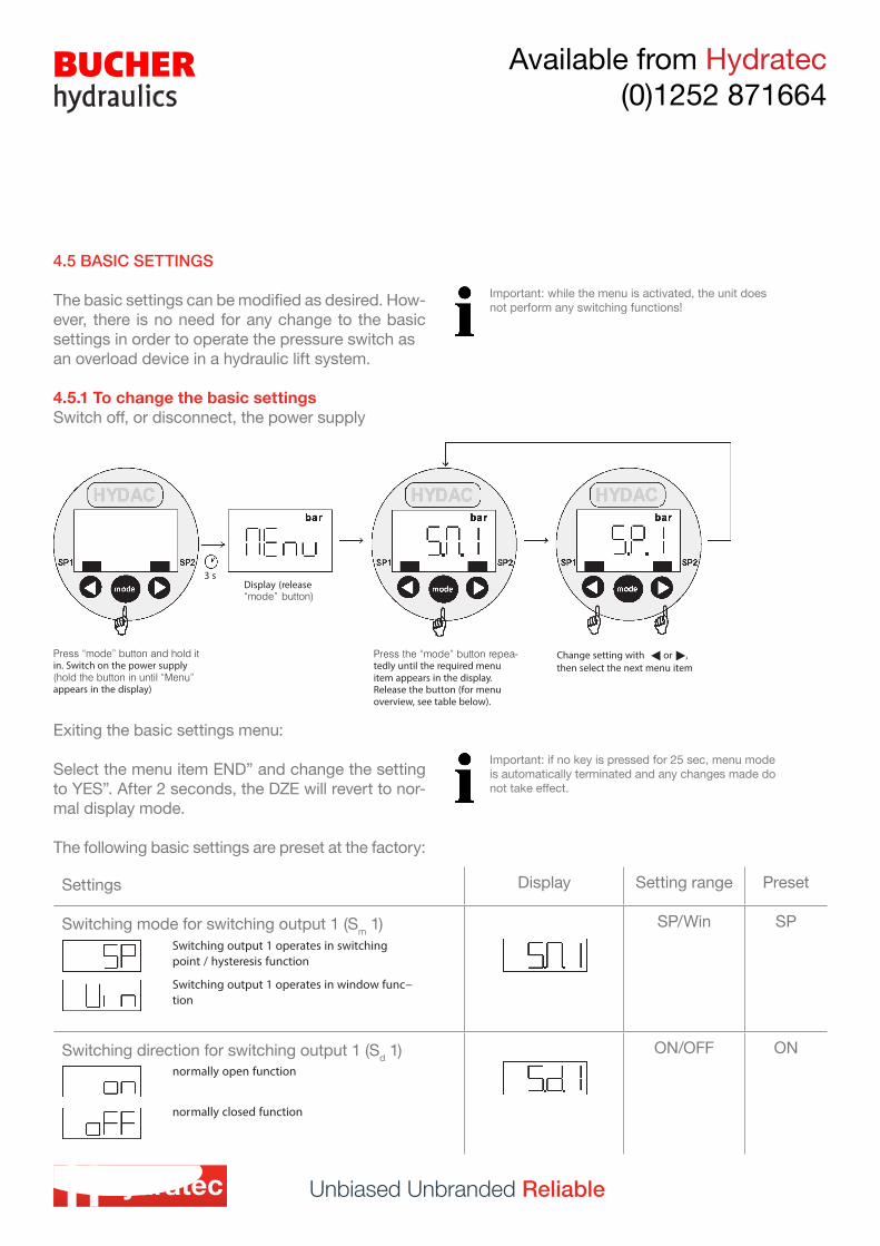
4.5 BASIC SETTINGS
The basic settings can be modified as desired. How-ever, there is no need for any change to the basic settings in order to operate the pressure switch asan overload device in a hydraulic lift system.
4.5.1 To change the basic settingsSwitch off, or disconnect, the power supply
Exiting the basic settings menu:
Select the menu item END” and change the setting to YES”. After 2 seconds, the DZE will revert to nor-mal display mode.
The following basic settings are preset at the factory:
Important: while the menu is activated, the unit does not perform any switching functions!
Important: if no key is pressed for 25 sec, menu mode is automatically terminated and any changes made do not take effect.
Settings Display Setting range Preset
Switching mode for switching output 1 (Sm 1) SP/Win SP
Switching direction for switching output 1 (Sd 1) ON/OFF ON
Unbiased Unbranded Reliable
Available from Hydratec (0)1252 871664
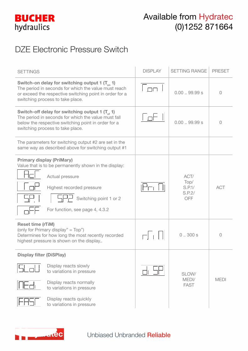
SETTINGS DISPLAY SETTING RANGE PRESET
Switch-on delay for switching output 1 (Ton 1)The period in seconds for which the value must reach or exceed the respective switching point in order for a switching process to take place.
0.00 .. 99.99 s 0
Switch-off delay for switching output 1 (Tof 1)The period in seconds for which the value must fall below the respective switching point in order for a switching process to take place.
0.00 .. 99.99 s 0
The parameters for switching output #2 are set in the same way as described above for switching output #1
Primary display (PriMary)Value that is to be permanently shown in the display:
Actual pressure
Highest recorded pressure Switching point 1 or 2
For function, see page 4, 4.3.2
ACT/ Top/ S.P.1/ S.P.2/ OFF
ACT
Reset time (rTiM)(only for Primary display” = Top”)Determines for how long the most recently recorded highest pressure is shown on the display..
0 .. 300 s 0
Display filter (DiSPlay)
Display reacts slowly to variations in pressure
Display reacts normally to variations in pressure
Display reacts quickly to variations in pressure
SLOW/ MEDI/ FAST
MEDI
DZE Electronic Pressure Switch
Unbiased Unbranded Reliable
Available from Hydratec (0)1252 871664
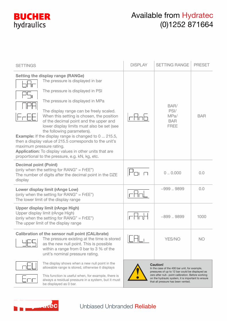
SETTINGS DISPLAY SETTING RANGE PRESET
Setting the display range (RANGe)The pressure is displayed in bar
The pressure is displayed in PSI
The pressure is displayed in MPa
The display range can be freely scaled.When this setting is chosen, the position of the decimal point and the upper and lower display limits must also be set (see the following parameters).
Example: If the display range is changed to 0 ... 215.5, then a display value of 215.5 corresponds to the unit’s maximum pressure rating.Application: To display values in other units that are proportional to the pressure, e.g. kN, kg, etc.
BAR/PSI/MPa/BARFREE
BAR
Decimal point (Point)(only when the setting for RANG” = FrEE”)The number of digits after the decimal point in the DZE display
0 .. 0.000 0.0
Lower display limit (rAnge Low)(only when the setting for RANG” = FrEE”)The lower limit of the display range
−999 .. 9899 0.0
Upper display limit (rAnge High)Upper display limit (rAnge High)(only when the setting for RANG” = FrEE”)The upper limit of the display range
−899 .. 9899 1000
Calibration of the sensor null point (CALibrate)The pressure existing at the time is stored as the new null point. This is possible within a range from 0 bar to 3 % of the unit’s nominal pressure rating.
The display shows when a new null point in the allowable range is stored, otherwise it displays
This function is useful when, for example, there is always a residual pressure in a system, but it must be displayed as 0 bar.
YES/NO NO
Caution!In the case of the 400 bar unit, for example, pressures of up to 12 bar could be displayed as zero after null− point calibration. Before working on the hydraulic system, it is important to ensure that all pressure has been vented.
Hydratec Lift Services LimitedUnit 1B, Blackbushe Business VillageYateley, HampshireGU46 6GA t · +44 (0) 1252 871664f · +44 (0) 1252 873601e · [email protected]
© Copyright 2016, Hydratec Lift Services Limited, All rights reserved.
*The technical and performance details contained within this document have been obtained from orig-inal manufacturers’ product descriptions. Hydratec Lift Services Ltd are providing this information as a guide only and cannot be held responsible should any performance promises or technical details be incorrect.
Hydratec Lift Services LimitedUnit A5, Axis Point Hareshill Business ParkHill Top Road, Heywood OL10 2RQ t · +44 (0) 1252 871664f · +44 (0) 1252 873601e · [email protected]
we service your clients as you
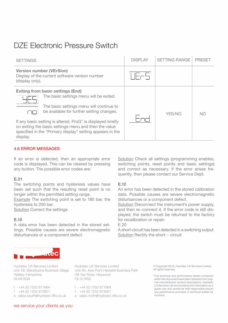
SETTINGS DISPLAY SETTING RANGE PRESET
Version number (VErSion)Display of the current software version number (display only).
Exiting from basic settings (End)The basic settings menu will be exited.
The basic settings menu will continue to be available for further setting changes.
If any basic setting is altered, ProG” is displayed briefly on exiting the basic settings menu and then the value specified in the “Primary display” setting appears in the display.
YES/NO NO
DZE Electronic Pressure Switch
4.6 ERROR MESSAGES
If an error is detected, then an appropriate error code is displayed. This can be cleared by pressing any button. The possible error codes are:
E.01The switching points and hysteresis values have been set such that the resulting reset point is no longer within the permitted setting range.Example The switching point is set to 180 bar, the hysteresis to 200 bar.Solution Correct the settings.
E.10A data error has been detected in the stored set-tings. Possible causes are severe electromagnetic disturbances or a component defect.
Solution Check all settings (programming enables, switching points, reset points and basic settings) and correct as necessary. If the error arises fre-quently, then please contact our Service Dept.
E.12An error has been detected in the stored calibration data. Possible causes are severe electromagnetic disturbances or a component defect.Solution Disconnect the instrument’s power supply, and then re−connect it. If the error code is still dis-played, the switch must be returned to the factory for recalibration or repair.E.20A short-circuit has been detected in a switching output.Solution Rectify the short − circuit